Melco Compilation

You also want an ePaper? Increase the reach of your titles
YUMPU automatically turns print PDFs into web optimized ePapers that Google loves.
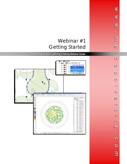
Webinar #1<br />
Getting Started<br />
DesignShop V9 Basic Lettering & Editing Webinar Guide<br />
w w w . m e l c o u n i v e r s i t y . c o m
Screen Overview<br />
Toolbars<br />
Main Bar<br />
Color Palette<br />
View Bar<br />
Dynamic Properties Bar<br />
View Window<br />
Input Toolbar<br />
Zoom Bar<br />
Scale/Status Bar<br />
Slow Redraw Bar<br />
DSV9_WO1_Getting_Started.pub 2 Rev: 06/03/09
Project View: Managing Your Elements<br />
Project Tab<br />
The Tabs<br />
Stitches Tab<br />
Navigator Tab<br />
The Levels<br />
Project Level<br />
Design Level<br />
Color Level<br />
Element Level<br />
Point Level<br />
DSV9_WO1_Getting_Started.pub 3 Rev: 06/03/09
Navigating Through The Workspace & A Design<br />
Selecting Elements<br />
Scaling Elements<br />
Rotating Elements<br />
Shift to scale proportionally<br />
ALT to scale center > out<br />
Shift to select multiple<br />
consecutive elements<br />
CTRL to select multiple nonconsecutive<br />
elements<br />
Zoom Functions<br />
DSV9_WO1_Getting_Started.pub 4 Rev: 06/03/09
Managing Colors<br />
Current Color<br />
Design Colors<br />
(Active Colors)<br />
Color Palette<br />
Background<br />
Color<br />
Current Color<br />
Background Color<br />
Design Colors (Active Colors)<br />
• List of colors currently being used in the<br />
design<br />
• Changing Colors<br />
• Right-click > edit color to<br />
change color of that swatch<br />
• Click and drag a swatch from<br />
the Palette to Design Colors<br />
• Right-click > Show/Hide (others/all)<br />
• Locked colors allow colors to remain in<br />
the active colors even when they are<br />
not currently in use.<br />
Color Palette<br />
• A small selection of available colors.<br />
• Right-click > Edit Color to change the<br />
color of that swatch<br />
Color Level in the Project View<br />
• Right-click on the color group> Color…<br />
to change thread color<br />
OR<br />
• Select the color group, click on the desired<br />
color from either the active colors<br />
or the color palette.<br />
Element Level<br />
• Color information is stored at the element<br />
level.<br />
• Changing the color of an element<br />
• Select the element(s) > click on<br />
the desired color swatch<br />
OR<br />
• Select the element(s) > Rightclick<br />
> Color…<br />
• The elements change color<br />
while all other elements remain<br />
DSV9_WO1_Getting_Started.pub 5 Rev: 06/03/09
Getting the Most<br />
From the Help System<br />
DesignShop V9 & AMAYA OS V9 Quick Reference Guide<br />
w w w . m e l c o u n i v e r s i t y . c o m
Accessing the Help System<br />
The help system contains the most current manuals for AMAYA OS or DesignShop.<br />
To access the help systems in either program, you can choose one of two ways.<br />
1. You could click on the “Help” drop-down on the<br />
menu bar and then select “Help Topics”<br />
OR<br />
2. Click on the Help Topics [?] icon on the main toolbar.<br />
Once opened, the help systems will look like this.<br />
DSV9_QRG_Help.pub 2 Rev: 04/28/09
Navigating the Help System<br />
Quick Links to various topics are contained within<br />
the middle red area of the screen.<br />
The Contents Tab is located on the left side of the<br />
screen, and contains the subjects within the help system.<br />
This is similar to the table of contents in books. Some subjects<br />
are grouped within folders. To view these, click on<br />
the [+] beside the folder or double click on the folder to<br />
expand it. Once you’ve found your topic, simply click on<br />
the topic to have it displayed in the window on the right.<br />
The Index Tab is an alphabetical listing of every feature<br />
in DesignShop. This is like the index in the back<br />
of many reference books. To display the information<br />
about a feature, double-click on the name of<br />
the feature, or select the topic and click on the<br />
“Display” button at the bottom of the window.<br />
The Search Tab is used to search for a specific<br />
topic. When a word is entered in the type field, a list of<br />
closely matched topics is displayed. Double-click on<br />
the topic to display the information.<br />
The controls on the upper left of the Help System<br />
window allow you to hide or show the Content, Index,<br />
and Search tabs. “Back” allows you to return<br />
to the previously displayed topics. “Print” will print a<br />
topic or an entire section.<br />
DSV9_QRG_Help.pub 3 Rev: 04/28/09
Help System Videos<br />
Many topics have a video clip to complement<br />
the written explanation. To access the<br />
videos, click on the film reel icon. This will<br />
launch the video in a player.<br />
Other Help System Information<br />
To exit the Help System, click on the “X” in the red<br />
box on the upper right corner of the window.<br />
“About DesignShop” located under the “Help”<br />
drop-down, will open a dialog box containing<br />
information about your level of software as well<br />
as the software version number.<br />
9.00.???<br />
Web Links are also available under the<br />
“Help” drop-down. To access these, an internet<br />
connection is required.<br />
DSV9_QRG_Help.pub 4 Rev: 04/28/09
Webinar #2<br />
Basic Lettering<br />
DesignShop V9 Basic Lettering & Editing Webinar Guide<br />
w w w . m e l c o u n i v e r s i t y . c o m
Creating a Lettering Segment<br />
1. Select the lettering tool by clicking on the [A]<br />
2. Choose your settings on the Dynamic Property Bar<br />
3. Click in the view window where you want the<br />
lettering segment to appear.<br />
1.<br />
2.<br />
3.<br />
4. Type your desired text on screen.<br />
5. Press [Enter] to complete the lettering segment<br />
[Ctrl] + [Enter] = Carriage return<br />
OR<br />
1. Select the lettering tool<br />
2. Click in the view window where you want the lettering<br />
3. Press [Enter] to go directly to properties.<br />
4. Click within the lettering box.<br />
5. Type your desired text in the box.<br />
6. Click “Apply” to see the text appear on screen.<br />
DSV9_WO2_Basic_Lettering.pub 2 Rev: 05/11/09
Lettering Properties<br />
Alphabet<br />
• Embroidery Alphabets (EA)<br />
• Code sheets<br />
• Operator Alphabets (OA)<br />
• True Type (TT)<br />
Letters<br />
Height, Width, & Slant Angle<br />
Kerning Marks & Trims<br />
DSV9_WO2_Basic_Lettering.pub 3 Rev: 05/11/09
On Screen Manipulation of Lettering<br />
Kerning<br />
Click on the handle of the<br />
letter and drag along the<br />
baseline.<br />
Holding [CTRL] while dragging<br />
will allow the letter to<br />
move off of the baseline<br />
Scaling<br />
Shift locks the aspect ratio<br />
while scaling<br />
Alt scales from the center<br />
out<br />
Rotate/Slant/Skew<br />
Letters (continued)<br />
As Digitized<br />
Connection Type<br />
Justification and Stitch Orders<br />
Justification<br />
Bottom Connect<br />
Horizontal Stitch Order<br />
Closest Point<br />
(CP)<br />
Vertical Stitch Order<br />
DSV9_WO2_Basic_Lettering.pub 4 Rev: 05/11/09
Line Types<br />
Straight<br />
Vertical<br />
Arc<br />
• Radius<br />
• Angle<br />
• Clockwise versus Counter Clockwise<br />
• Changing radius & angle graphically<br />
• Hold alt to snap to 15° increments<br />
Custom<br />
• Adding points along the baseline<br />
• Straight points (left click) = triangle<br />
• Curve points (right click) = circle<br />
Perspective<br />
• Moving points creates a linear perspective<br />
and adds the illusion of depth.<br />
• Points can be added and moved to<br />
change shape.<br />
Envelope<br />
• Points can be added and moved to<br />
change shape.<br />
• Will affect letters evenly – no linear perspective.<br />
• Scale to Fit squishes or stretches the<br />
current lettering to fit the shape created<br />
by the envelope.<br />
DSV9_WO2_Basic_Lettering.pub 5 Rev: 05/11/09
Spacing<br />
Auto Kern<br />
• Adjusts the spacing between<br />
each pair of letters to be a<br />
specified percentage of the<br />
letter height.<br />
Line Spacing<br />
• Adjusts the spacing between<br />
lines of type<br />
Horizontal Spacing<br />
• Adjusts the spacing between<br />
all the letters<br />
Vertical Spacing<br />
• Adjust the spacing between<br />
letters to create a stair-step<br />
effect<br />
Word Spacing<br />
• Adjusts the spacing between<br />
words to be a specified percentage<br />
of the height.<br />
Changing the Color of Letters<br />
Text: RAINBOW<br />
Alphabet: (OA) Curly<br />
Height: 1.0”<br />
1. Create a lettering segment with the<br />
above properties.<br />
2. Select the lettering segment.<br />
3. Select the letter you wish to change the color<br />
of by clicking on the handle of the letter.<br />
4. Click on the color palette color swatch of<br />
the color you wish the letter to become.<br />
5. Continue with the rest of the letters<br />
DSV9_WO2_Basic_Lettering.pub 6 Rev: 05/11/09
Quick Reference<br />
Guide Lettering V9<br />
DSV9_QRG_Lettering 1 Rev: 4/16/09
Icon Identification<br />
1. Edit Mode – to deselect elements, click on a blank area of your screen.<br />
2. Pointer over element – you can move an element.<br />
3. The eight black boxes around an element are scaling boxes. The four corner<br />
boxes scale vertical and horizontal. The middle boxes scale just vertical or<br />
horizontal.<br />
4. The open boxes around an element are rotating or skewing boxes.<br />
5. Slant angle on screen – click on the center hollowed out box and drag left or<br />
right.<br />
6. Pointer over a digitized straight input point.<br />
• Select an input point , click on it - it will become filled in<br />
7. Pointer over a digitized curve input point.<br />
• Select an input point , click on it - it will become filled in<br />
8. Pointer over any wireframe line. Left click to add straight input points. Right<br />
click to add curve input points.<br />
DSV9_QRG_Lettering 2 Rev: 4/16/09
Lettering<br />
Create a lettering element<br />
1. Click on the lettering tool on the input toolbar.<br />
2. Left click on the screen workspace (View Window) where you want your lettering<br />
text to appear (notice the cursor arrow has an A attached to it).<br />
3. A flashing cursor is displayed on your screen.<br />
4. Start typing your text.<br />
5. Press the Enter Key (on the key board) when finished with text.<br />
OR<br />
6. Click on the lettering tool on the input toolbar.<br />
7. Left click on the screen workspace (View Window) where you want your lettering<br />
text to appear (notice the cursor arrow has an A attached to it).<br />
8. Press the enter key on the keypad to go directly to the properties dialog box.<br />
9. Type your lettering in the text box then click on “Apply” or “OK”.<br />
Re-opening a lettering element properties box<br />
1. With the selection tool, double-click on the text.<br />
2. The Object Properties Box will appear.<br />
3. Make the changes; click on the desired tabs if needed.<br />
4. Click OK.<br />
Positioning the lettering element<br />
1. Select the text you want to move on the screen by placing your mouse on the<br />
center of that text.<br />
*NOTE: Your mouse pointer will display a 4-headed directional arrow symbol<br />
next to it<br />
2. Left click and drag to move the element.<br />
DSV9_QRG_Lettering 3 Rev: 4/16/09
Scale and rotate lettering elements<br />
1. Click on the lettering element. Click and hold the shift key to scale proportionally (on<br />
any of the 4 corner handles). Click and hold alt key to scale from center out (on any<br />
of the 4 solid corner handles).<br />
Note: The user will get a wireframe preview when clicking and dragging points on an<br />
outline. This feature is particularly important for the user to visually see how big the<br />
lettering will be. This feature works the same when moving designs on the screen.<br />
2. Click on the element again to enter rotate mode. Notice that the handles become<br />
hollow. Click and hold on any of the 4 open corner handles.<br />
3. Scaling, Rotating and Slanting individual letters<br />
• Click on the “X” to select the individual letter.<br />
• Move individual letters left or right. To move the letter up or down, hold the<br />
control key on the keypad.<br />
• Scaling individual letters – Use the shift key and click on one of the corner<br />
handles to scale proportionally (the object remains a lettering element).<br />
• Rotating/Slanting individual letters – allows the user rotate individual letters.<br />
Click and drag on the one of the four corner handles<br />
DSV9_QRG_Lettering 4 Rev: 4/16/09
Wireframe Editing Mode<br />
1. Edit the wireframe points as well as entry and exit points<br />
• Select the letter (Click on the “x” in the center of the letter)<br />
• On the View toolbar, click on the tool “Wireframe Editing Mode”<br />
• You will now be able to move each wireframe point as well as the start and<br />
exit points. The start point is represented by a green circle and the exit it<br />
represented by a red X<br />
Add color changes between letters<br />
1. Select the letter (click on the “x”) that you want to change the color. Then, click on<br />
the color box on left side of screen. Your letter will now be the color you just clicked<br />
on.<br />
DSV9_QRG_Lettering 5 Rev: 4/16/09
Auto Borders<br />
All of the following can be added or changed:<br />
• Stitch Types: Satin or Walk/Bean Stitch, Appliqué and Tackle<br />
• Density/Column Width adjustments or Stitch lengths<br />
• Color Changes/Border sequence<br />
• You also have the option of stitching all the inside of the letters first then the border<br />
by selecting – Stitch Borders Last<br />
DSV9_QRG_Lettering 6 Rev: 4/16/09
Using the Dynamic Toolbar to make quick changes to your lettering elements<br />
This toolbar is only displayed when an element or input tool is selected<br />
Change the Stitch Type<br />
1. Click on the Text<br />
2. Click on Stitch drop down arrow on the dynamic toolbar (see above)<br />
3. Click on the stitch of choice (satin, fill, E-stitch, zigzag, and edge fill)<br />
Change the Alphabet<br />
1. Select the lettering on the screen<br />
2. On the dynamic toolbar, click on the drop down arrow next to “Alphabet”<br />
3. Roll the mouse down to select the desired alphabet<br />
DSV9_QRG_Lettering 7 Rev: 4/16/09
Add Underlay<br />
1. Click on text on the screen<br />
2. Click on underlay drop down arrow on tool bar<br />
3. Click on Underlay you want to use<br />
4. You can also double click on your text and set up “Auto Underlay” in the Object<br />
Properties box<br />
DSV9_QRG_Lettering 8 Rev: 4/16/09
5. This option allows you to set parameters to automatically place different underlay’s<br />
for different size ranges of elements (see below). Click on the check box next to<br />
“Enable Auto-Underlay” then click on the input box - the following dialog box is<br />
displayed. You can change the parameters or leave the defaults.<br />
DSV9_QRG_Lettering 9 Rev: 4/16/09
Lettering - Object Properties Dialog box<br />
Adjust the short stitches<br />
1. Short stitches should remain on all the time except on small letters (.25 and below).<br />
Short Stitches On<br />
Short Stitches Off<br />
2. To turn on or off short stitches, double click on the element to open the object<br />
properties dialog box. Click on “Top Stitching” then left click the check mark next to<br />
short stitches. This will turn off short stitches. It is also available as a toggle on the<br />
dynamic properties bar.<br />
DSV9_QRG_Lettering 10 Rev: 4/16/09
Horizontal Stitch Order for lettering<br />
1. Create a Lettering element.<br />
2. Double click on the element to open the Object Properties Box<br />
3. Select the “Horizontal Stitch Order” button to sew the lettering. You can choose<br />
left to right, right to left, or center out.(note* center out is great for hats and jacket<br />
back lettering in big hoops)<br />
4. Click on OK.<br />
Vertical Stitch Order for lettering<br />
1. Create a Lettering Element using more than one line of text.<br />
2. Double click on the element to open the Object Properties Box<br />
3. Select the “Vertical Stitch Order” button to sew the lettering. You can choose top<br />
to bottom, bottom to top or line wrapping. (Bottom to top would also be a good<br />
choice for lettering on the front of caps.)<br />
4. Click on OK.<br />
DSV9_QRG_Lettering 11 Rev: 4/16/09
Adjust the space between two letters<br />
1. Create a Lettering Element using the word “Tony” with Diane Script<br />
2. Notice the “T” is too far away from the rest of the word.<br />
3. Click and Drag on the X of the letter “T” moving it right or left when needed<br />
(common with script texts).<br />
OR<br />
4. From the Object Properties Dialog box<br />
5. Click on the button to decrease space (see diagram below).<br />
*NOTE: You may have to click more that once to achieve desired spacing.<br />
6. Click Apply to see the changes or OK to close the Properties box.<br />
*NOTE:<br />
decreases space between two letters.<br />
increases space between two letters.<br />
DSV9_QRG_Lettering 12 Rev: 4/16/09
Adjusting the space between every letter or every line<br />
1. In the Object Properties Box, under lettering and then under spacing, you can set<br />
horizontal, line or vertical spacing.<br />
• A positive number increases space, a negative number decreases space.<br />
2. Line Spacing adjusts the space between the lines of type.<br />
3. Horizontal Spacing adjusts the space between all of the letters.<br />
4. Use Vertical spacing to stair step the lettering (This works best with only one line<br />
of type.)<br />
Line Types<br />
1. Create the lettering element, then select the text you would like to adjust the<br />
baseline.<br />
2. On the Dynamic toolbar select the baseline style you wish to use by clicking on the<br />
drop down arrow (next to the word “line”) then choose the baseline.<br />
• Custom – click on the baseline and use right clicks to insert curve points or<br />
left clicks to insert straight points. Once the points have been inserted, you<br />
can click on them and drag to achieve the desired line shape.<br />
DSV9_QRG_Lettering 13 Rev: 4/16/09
• Arc - Adjust the arc radius angle.<br />
• Vertical<br />
• Perspective – Click and drag on any of the four corner points<br />
DSV9_QRG_Lettering 14 Rev: 4/16/09
• Envelope – click on the baseline and use right clicks to insert curve points or left<br />
clicks to insert straight points.<br />
Shadow Effect (DS Pro +)<br />
The shadow feature can be used on letters and simple design shapes<br />
DSV9_QRG_Lettering 15 Rev: 4/16/09
1. Type letters for shadow effect.<br />
2. Click on the Object Drop Down Menu<br />
3. Select Shadow<br />
4. Select Stitch Type (see picture below)<br />
5. You can adjust Angle, Offset and Overlap (or accept defaults).<br />
6. Click on OK.<br />
DSV9_QRG_Lettering 16 Rev: 4/16/09
MELCO ALPHABETS<br />
<strong>Melco</strong> offers many alphabets or “keyboard lettering” styles for DesignShop software. The<br />
help system in the DesignShop software has all of the available alphabets and the code<br />
sheets for each one. Click on “Help” then “Help Topics” from the Help pull down menu, or<br />
press F1 while in DesignShop. Then click on the “Alphabets” button to access the code<br />
sheets. Each code sheet gives a 3D view of the characters and the recommended minimum<br />
and maximum sewing size. The code sheets also include a chart of all the available<br />
European or extended characters available in each alphabet.<br />
All of the alphabet code sheets contain a recommended minimum and a maximum sewing<br />
size. This recommended parameter should be used and followed, but this does not mean<br />
that going outside of these limits will produce bad results. Many of the alphabets can be<br />
used at larger or smaller sizes if parameters such as Column Width, Letter Width, Density,<br />
Short Stitches, Column Fill and Underlay are adjusted accordingly.<br />
To fully understand <strong>Melco</strong> keyboard lettering, it must be understood that each and every<br />
character is digitized separately and is then compiled and put into one unique alphabet file<br />
that is understood by <strong>Melco</strong> DesignShop software. As each character is individually<br />
digitized, each alphabet will have its own way of reacting to size and parameters used when<br />
setting up the lettering desired. Some alphabets are digitized to be used at smaller sizes<br />
than others. Parameters used for one may not sew the same for another.<br />
Closest point alphabets are digitized so they will connect at the closest point of each letter<br />
next to each other. Using these alphabets will minimize UN-wanted trims between letters.<br />
A closest point alphabet will be listed in the lettering list with a “CP” on the end. An example<br />
will look like this: FULL BLOCK CP.<br />
Probably the most important items to insure good results are the proper settings for the<br />
garment type being sewn on, and using the proper backings and or topping. All alphabet<br />
code sheets produced before July of 2001 have a minimum and maximum setting. These<br />
settings were determined on a non-stretch type of material. The settings may need to be<br />
adjusted for use on a knit or sweat material. All new alphabets have recommended settings<br />
for knits, sweats and non-stretch fabrics in the code sheets. These settings are a good<br />
starting place, but may need adjusting for the particular garment material being used. Knit<br />
materials for instance, can vary in material density, thickness and how much they stretch.<br />
Settings for one type of knit material may not work 100% for another.<br />
Some alphabets currently being sold by <strong>Melco</strong> contain tie stitches at the end of each letter in<br />
the alphabet. These tie stitches are what "ties down" the stitching at the end of each letter.<br />
DesignShop allows you to add tie stitches to a lettering job from the Tie In And Tie Off sub<br />
window of Object Properties. However, because the tie stitches are already digitized into the<br />
alphabet, the result is multiple tie stitches that will create an undesirable knotting effect. To<br />
remove all existing tie stitches from all installed alphabets in DesignShop, click on the "Tools<br />
Menu", "Convert Alphabets" and then click on “Remove Ties”. Use the "Tools Menu",<br />
“Restore Alphabets” feature to restore the tie stitches digitized back into the alphabet<br />
characters that originally had them if so desired. However, Tie in stitches is usually not<br />
digitized into the current alphabets. Tie in stitches are a lock stitch that is sewn at the<br />
beginning of each letter. You may want to use this feature when trimming between each<br />
DSV9_QRG_Lettering 17 Rev: 4/16/09
letter to avoid a possible “thread pullout” when the machine starts sewing the next letter<br />
after a trim.<br />
As a general rule, when sewing on knit or sweat materials, column width should be<br />
increased. Proper backings should be used, and in most cases a topping such as Solvy<br />
should also be used. Many of the recommended minimum settings listed in <strong>Melco</strong> alphabets<br />
will not work on knits or sweats, and may need to be adjusted to different values. When<br />
increasing the column width to compensate for material type, the letters that have enclosed<br />
areas such as an “a” may close in the center when sewn. If this is noticed, the size of the<br />
lettering should be increased to allow for the added column width. In most cases when<br />
sewing on knits or sweats an edge walk underlay is desired, and in some cases (larger<br />
sizes) an edge walk along with a center walk should be used. Very thin column lettering may<br />
only require a center walk at small sizes. Density on knits and sweats is usually set denser<br />
than on a stable material. Block styles of alphabets used at small sizes sew much cleaner<br />
and crisper than script alphabets at the same size. In most cases when doing small lettering<br />
on knits or sweats a block style of alphabet without serifs will give the best results. Using<br />
some scrap material for testing that is like the garment to be sewn on is highly<br />
recommended until what works best for you and your machines is determined.<br />
Following are a few recommendations that you may want to try when sewing keyboard<br />
lettering.<br />
Large letters<br />
If the alphabet letter height is increased beyond the maximum recommendation, sew quality<br />
may suffer. The column stitch may get too wide and can create an undesirable effect.<br />
• Change the column stitch type from a satin stitch to a fill stitch. The stitch count will<br />
increase, but the sew quality will improve.<br />
• Zigzag or Edge Walk underlay will help to stabilize the stitches on the fabric.<br />
Small letters<br />
When using keyboard lettering for small letters, these tips may help your sew quality.<br />
• Turn off short stitches for small letters. This can improve sew quality as well as help to<br />
reduce thread breaks.<br />
• Increasing the column width (Pull Comp.) will help the lettering from sinking into a knit.<br />
Different alphabets will require different column widths, as they are all different in width<br />
at the default value.<br />
• The column density value should be increased. The value will depend on the fabric.<br />
• The travel stitch length should be in the range of 18 - 25.<br />
DSV9_QRG_Lettering 18 Rev: 4/16/09
Small Lettering<br />
There are a few things to remember when sewing small letters. Always check the Alphabet<br />
Code Sheets for the recommended letter height for your selected Alphabet. Some Alphabets<br />
were not created to sew small. If the alphabet you have chosen cannot be sewn as small as<br />
you would like, choose a different alphabet. Material thickness may need to be slightly<br />
increased to achieve good sew quality. A more stable piece of backing and a piece of Solvy<br />
will help keep small lettering from sinking into the fabric. Here is a list of problems that may<br />
occur when sewing small letters and how to fix them:<br />
Symptom Possible Cause Solution<br />
Bobbin showing on top of the<br />
fabric (bobbin pull).<br />
Frayed Threads<br />
Sharp corners and curved<br />
areas look choppy<br />
Excessive Thread Breaks<br />
Looping<br />
Columns are uneven and<br />
distorted.<br />
Columns are too skinny,<br />
and/or material thickness is<br />
too low. It could also be that<br />
you are sewing too quickly.<br />
Columns are too skinny or<br />
stitches are too dense. Needle<br />
is too large, or is damaged<br />
Tiny stitches in curved areas.<br />
Needle is too large.<br />
Stitching is too dense or<br />
columns are too skinny.<br />
Needle is too large or<br />
damaged.<br />
Columns are too skinny or<br />
stitching is too dense. Material<br />
Thickness value is too high.<br />
Lettering is too small. Fabric<br />
needs more stability. Columns<br />
are too skinny.<br />
Increase “Width/Pull<br />
Compensation” (some small<br />
letters may need to go as high<br />
as 190%). Increase Material<br />
Thickness value.<br />
Increase “Width/Pull<br />
Compensation.” Loosen<br />
density (.3 inch letter should<br />
have a density of 4.5 or higher).<br />
Use a smaller or new needle.<br />
Turn Short Stitches Off. Use a<br />
smaller needle.<br />
Increase “Width/Pull<br />
Compensation.” Loosen<br />
density. Use a less aggressive<br />
underlay. Use a smaller needle.<br />
Increase “Width/Pull<br />
Compensation.” Loosen<br />
density. Lower Material<br />
Thickness Value. Check to see<br />
if your acti-feed lower limit isn’t<br />
too high.<br />
Check the recommended<br />
minimum letter height. Use a<br />
more stable backing. Increase<br />
the “Width/Pull Compensation.”<br />
Turn Short Stitches Off. Use a<br />
topping like “Solvy.”<br />
DSV9_QRG_Lettering 19 Rev: 4/16/09
Understanding &<br />
Changing Stitch Types<br />
DesignShop V9 Quick Reference Guide<br />
w w w . m e l c o u n i v e r s i t y . c o m
Changing Stitch Types<br />
When an element or an input tool is selected, you can change the stitch type using<br />
the drop-down on the Dynamic Properties Bar. If it is already open, you could also<br />
use the Object Properties window.<br />
If you have a walk element or input<br />
tool selected, you will have the<br />
stitch type choices below.<br />
If you have a column or complex fill<br />
element or input tool selected, you will<br />
have the stitch type choices below.<br />
Common Stitch Types for Walk Elements<br />
Walk Normal<br />
• Creates a single running stitch<br />
• Used for digitized travel stitches<br />
• Used to travel from one point in a design<br />
to another without trimming<br />
• Big factor in design efficiency<br />
• Used for very small detail work<br />
• Used for a digitized underlay<br />
Walk Bean<br />
• Creates a multi-layered running stitch<br />
• Each stitch steps forward, back, and<br />
forward again.<br />
• Increasing the Bean Thickness would<br />
increase the number of times each<br />
stitch repeat.<br />
• Used for detail work<br />
• Sometimes used for borders<br />
DSV9_QRG_Stitch_Types.pub 2 Rev: 04/28/09
Common Stitch Types for Multi-Stitch Line Elements<br />
Satin<br />
• Rounded, shiny, sculptural, stays<br />
up out of material<br />
• Saves Stitches<br />
• Limited Range (10-60pts)<br />
• Stitches can change direction<br />
through the form (like in an “S”)<br />
• Stitches usually run perpendicular<br />
to the edge – across the form<br />
Zig Zag<br />
• Usually used as tack-down stitch<br />
for appliqué<br />
E-Stitch<br />
• Used mostly as an appliqué<br />
tack-down stitch<br />
Fill<br />
• Usually used for larger areas<br />
• Flatter look, although you can<br />
create patterns within the fills<br />
• Sinks stitches within the form<br />
• Raises stitch count<br />
Tackle<br />
• Tack-down for appliqué<br />
• Used mostly for numbers on<br />
sports items / sports uniforms<br />
Edge Fill<br />
• Sinks stitches within the form<br />
• Stitches run parallel to the edge<br />
• Used mostly for special effects<br />
Auto Stitch Type<br />
By checking the “Auto” box beside the stitch<br />
type drop-down in the object properties box, you<br />
can enable Auto Stitch Type.<br />
This function bases the stitch type off of the<br />
average size of a multi-stitch line element. It<br />
defaults to satin stitches for smaller objects and<br />
fills for larger objects.<br />
To access the properties for auto, click on<br />
the […] beside it.<br />
DSV9_QRG_Stitch_Types.pub 3 Rev: 04/28/09
The<br />
Color System<br />
DesignShop V9 Quick Reference Guide<br />
w w w . m e l c o u n i v e r s i t y . c o m
Accessing the Color System<br />
Object Properties<br />
Project View<br />
Color Palette<br />
The Color System in DesignShop is comprised of three parts. Many times, only one<br />
or two of these sections need to be accessed to affect the desired change.<br />
The Color Palette is on the left side of the screen when you load DesignShop. It is<br />
a toolbar and can be moved wherever the user finds most useful. Should the<br />
toolbar get closed, it can be retrieved by clicking on View > Toolbars, and<br />
checking “Mini-Palette Toolbar”.<br />
The Object Properties box is accessed by selecting an element or elements<br />
and right-clicking within the selection box. Then, choose “Properties” from the<br />
options listed. Another way to get to the Object Properties box is by clicking on<br />
View menu and selecting “Properties”.<br />
The Project View is third part of the color system. When DesignShop is first<br />
loaded, it is located on the far right of the screen. If you cannot find it, click on<br />
“View” then “Project Views”, then choose “Project View 1”.<br />
DSV9_QRG_Color_System.pub 2 Rev: 05/21/09
The Color Palette<br />
Current Color<br />
Design Colors<br />
(Active Colors)<br />
Color Palette<br />
Background<br />
Color<br />
Current Color<br />
• The current color displays the color of<br />
the currently selected element. If an<br />
input is selected, it displays the color<br />
that will be used by the tool.<br />
• To change the current color, click on a<br />
color in the design colors or the color palette.<br />
You could also click on the current<br />
color to open the Color Properties window.<br />
Background Color<br />
• The background color allows you to<br />
change the background color of your<br />
view window. This can help mimic the<br />
color of garment on which the design is<br />
to be sewn.<br />
• To change the background color, click<br />
on the background color button (the<br />
sliver of color to the right of the current<br />
color block). This will open the Color Properties<br />
window. You can then choose a<br />
new color for the background.<br />
Color Palette<br />
• A small selection of available colors.<br />
• Left-clicking on a block will change the<br />
currently selected elements to that<br />
color. If no elements are selected, it will<br />
change the current color to that color.<br />
• Right-click on the block and choose “Edit<br />
Color” to change the color of that block.<br />
Design Colors (Active Colors)<br />
• Design Colors displays the colors being<br />
used in the design.<br />
• Changing Colors<br />
• Changing the color of a block in<br />
Design Colors will change every<br />
instance of that thread color in<br />
the design. If the design used the<br />
same color three times, and that<br />
thread color was changed in the<br />
Design Colors, all the occurrences<br />
of that color would be changed<br />
to the new color.<br />
• Right-click > edit color to<br />
change color of that block<br />
• Click and drag a block from the<br />
Palette to Design Colors<br />
• Right-click > Show/Hide (others/all)<br />
• Locked colors allow colors to remain in<br />
the active colors even when they are<br />
not currently in use. To lock a color,<br />
right-click on the block and choose<br />
“Locked” from the menu.<br />
DSV9_QRG_Color_System.pub 3 Rev: 05/21/09
Color Properties<br />
If accessed from the color palette on the<br />
left side of the screen, the color properties<br />
window can be used to change the<br />
thread color of the current color, an active<br />
color block, or a palette color block.<br />
If accessed from the project view on the right<br />
side of the screen, the color properties window<br />
can be used to change the thread<br />
color of the currently selected elements.<br />
A new color can be selected by scrolling<br />
through either of the scrollable color charts<br />
and clicking on the desired color swatch. If<br />
the thread number is known, it can simply be<br />
entered in the “Find Number” field.<br />
In the preview on the left, the original color is<br />
shown on top with the newly chosen color<br />
underneath. Both colors are ringed in the<br />
background color. When you click “Apply”,<br />
the original color will change to the new.<br />
Old Color<br />
Background Color<br />
New Color<br />
If the desired color is not an ARC Poly color,<br />
other thread charts are available from the<br />
“Color Chart” drop-down menu.<br />
DSV9_QRG_Color_System.pub 4 Rev: 05/21/09
Color in the Project View<br />
In the Project View, you will notice that there<br />
is a color level. These color blocks represent<br />
the color sequence. If you click on the color<br />
block, you will select every element within<br />
that instance of color. If that thread color is<br />
repeated later in the sequence, you will not<br />
be selecting those elements.<br />
Color Level in the Project View<br />
• Right-click on the color group> Color…<br />
to change thread color.<br />
OR<br />
• Select the color group, click on the desired<br />
color from either the active colors<br />
or the color palette.<br />
Element Level<br />
• Color information is stored at the element<br />
level.<br />
• Changing the color of an element<br />
• Select the element(s) > click on<br />
the desired color block in the<br />
color palette<br />
OR<br />
• Select the element(s) > Rightclick<br />
> Color… , then choose<br />
the desired color in the color<br />
properties window.<br />
• The selected elements<br />
change color while all other<br />
elements remain<br />
Merging Colors in the Project View<br />
Auto Merge Color Blocks<br />
Merge Color<br />
In the Project View, if two identical color blocks<br />
exist back to back, you can have the software<br />
automatically merge those color blocks. This<br />
will create a more efficient design with less<br />
color changes when sent to a machine.<br />
If you want to manually merge color blocks,<br />
you can click on the small brown arrow to the<br />
right of a color block to force it to adopt the<br />
color above it in the project view.<br />
DSV9_QRG_Color_System.pub 5 Rev: 05/21/09
Webinar #3<br />
Object Properties<br />
DesignShop V9 Basic Lettering & Editing Webinar Guide<br />
w w w . m e l c o u n i v e r s i t y . c o m
Object Properties<br />
Saving Properties as Default<br />
Copy & Paste Properties<br />
DSV9_WO3_Object_Properties.pub 2 Rev: 06/02/09
Top Stitching: Stitch Types<br />
Satin<br />
• Rounded, shiny, sculptural, stays<br />
up out of material<br />
• Saves Stitches<br />
• Limited Range (10-70pts)<br />
• Stitches can change direction<br />
through the form (like in an “S”)<br />
• Stitches usually run perpendicular<br />
to the edge – across the form<br />
Fill<br />
• Usually used for larger areas<br />
• Flatter look, although you can<br />
create patterns<br />
• Sinks stitches within the form<br />
• Raises stitch count<br />
Zig Zag<br />
• Usually used as tack-down stitch<br />
for appliqué<br />
E-Stitch<br />
• Used mostly as an appliqué<br />
tack-down stitch<br />
Edge Fill<br />
• Sinks stitches within the form<br />
• Stitches run parallel to the edge<br />
• Used mostly for effect<br />
Tackle<br />
• Tack-down for appliqué<br />
• Used mostly for numbers on<br />
sports items / sports uniforms<br />
DSV9_WO3_Object_Properties.pub 3 Rev: 06/02/09
Top Stitching Continued<br />
Auto Stitch Type<br />
• Bases the stitch type off of the average<br />
size of an element<br />
• Defaults to satins for smaller objects<br />
and fills for larger objects<br />
• Properties for Auto are available in the<br />
[…] box<br />
Short Stitch<br />
Toggle on the Dynamic Properties Bar<br />
• Alternates the stitch lengths on the insides<br />
of tight angles and curves<br />
• Helps prevent holes and thread breaks<br />
on the inside of forms<br />
• More settings are under Top Stitching ><br />
Advanced<br />
• Width<br />
Density<br />
• Density is the measurement of space<br />
between the stitches<br />
• Longer satin stitch lines need a tighter<br />
density<br />
• Shorter stitch lines need a lighter density<br />
• Whole number jumps in density are rare<br />
Auto-Density<br />
• Auto-Density bases the density of an<br />
element on the width of the stitch line.<br />
• Wider stitch lines = tighter the density.<br />
• The values table is accessible through<br />
the […] beside it.<br />
• When Auto-Density is checked, the<br />
Density field changes to a percentage.<br />
This allows you to easily adjust the density<br />
while keeping the variances based<br />
on width.<br />
“Use Fill for stitch lines greater than:”<br />
• Allows users to specify at what stitch<br />
line length a satin will be turned to a fill.<br />
• This prevents satin stitches for exceeding<br />
appropriate lengths and snagging<br />
or pulling out of the garment.<br />
• The properties of the fill are listed below.<br />
• Defaults to random to hide the needle<br />
penetrations.<br />
DSV9_WO3_Object_Properties.pub 4 Rev: 06/02/09
Underlay<br />
Center Walk<br />
1. Good for smaller lettering and thinner elements<br />
2. Adds one line of stitching down the middle of an element<br />
• Stitch Length<br />
• Shorter stitches follow curves more accurately<br />
• Longer stitches stay out of the material<br />
• Avoid stitch lengths shorter than 15 pts<br />
Edge Walk<br />
1. Cleans up edges of elements<br />
2. Used for wider elements<br />
3. Adds a line of stitching just on the inside of the edges of an element<br />
• Inset<br />
• Percentage – Width<br />
• Adjusts the width of the edge walk<br />
• Absolute – Border Margin<br />
• Adjust the inset of the edge walk<br />
Zig Zag<br />
1. Good for tacking down the nap of material<br />
2. Adds one line of stitching up the middle of an element and then zig zags<br />
back.<br />
• Density<br />
• Adjusts the density of the underlay<br />
Double Zig Zag<br />
1. Adds two layers of zig zag stitching underneath an element<br />
2. The layers cross over each other<br />
Fill<br />
1. Creates a light fill underneath the top stitching<br />
• Angle<br />
• The angle of the underlay in relation to the angle of<br />
the topstitching<br />
DSV9_WO3_Object_Properties.pub 5 Rev: 06/02/09
Underlay Options<br />
Lettering – Use Continuous Underlay<br />
• Underlays the entire letter before coming<br />
back over with the top stitching.<br />
• Helps prevents the segments of the letters<br />
from pulling gaps in the sewout.<br />
• Good for smaller lettering<br />
Auto-Underlay<br />
• Enable Auto-Underlay<br />
• Allows you to specify different underlays<br />
for different size ranges of elements.<br />
Pull Comp<br />
Lock XY<br />
• Keeps the Pull Compensation equal in both vertically<br />
and horizontally<br />
Pull Comp<br />
• Multiplies the element width by the specified<br />
percentage<br />
• Affects wider areas faster than thinner areas<br />
• Used to compensate for the pull of stitches in<br />
fabric<br />
Pull Offset<br />
• Widens the element by specified amount on<br />
each side<br />
• Completely even all the way through the form<br />
Max Pull Comp<br />
• Specified Maximum value for pull comp.<br />
• Prevents pull comp from getting too wide on<br />
areas with large line length when pull percentage<br />
amount is specified.<br />
Small Column Pull Comp Scale<br />
• Adjusts smaller elements differently than larger<br />
ones.<br />
• Small Column Scale %<br />
• Adds additional pull compensation for<br />
smaller elements<br />
• Small Column Width<br />
• A small column is defined by any element<br />
width falling below this value.<br />
Column Width<br />
• Min Col Width<br />
• If a stitch line falls short of this value, it<br />
will be extended to meet this length.<br />
• Max Col Width<br />
• If a stitch line width exceeds this value, it<br />
will be adjusted to fit this length.<br />
DSV9_WO3_Object_Properties.pub 6 Rev: 06/02/09
Tie In & Tie Off<br />
DSV9_WO3_Object_Properties.pub 7 Rev: 06/02/09
Density and Auto Density<br />
Density: Measures the distance between the stitches. The distance that separates the zig and<br />
zag of the stitches is used as the display for density. The larger the value for density, the looser<br />
the stitching. The smaller the value for density, the tighter the stitching will become. See<br />
diagram below to illustrate a 4, 8 and 15 density setting.<br />
Auto-Density: Many columns are not going to be straight from beginning to end. The width may<br />
increase, decrease, and increase again. In this situation it is very useful to use the Auto-Density.<br />
To implement the Auto-Density function, left-click in the box (located in Object Properties<br />
under “Top Stitching”). Click again to remove the check mark (this turns Auto-Density off).<br />
Below is an example (FIG. 1) of Density (Normal Setting) and (FIG. 2) of Auto-Density turned on.<br />
DSV9_QRG_Density_Auto_Density 1 Rev: 6/2/09
Clicking the button next to Auto Density brings up the following dialog. This enables<br />
you to define your own auto density settings based on the column width.<br />
DSV9_QRG_Density_Auto_Density 2 Rev: 6/2/09
Column 1, Column 2, & Single Line<br />
Input Methods<br />
DesignShop V9 Basic Digitizing Quick Reference Guide<br />
w w w . m e l c o u n i v e r s i t y . c o m
Digitizing Tools and Basic Functions<br />
Selecting a Tool<br />
Click on the desired tool in the input toolbar<br />
• If you don’t see the desired tool, it may be<br />
necessary to select the tool from a flyout.<br />
• To access a flyout, click and hold on<br />
the tool within the same tool family.<br />
After a half a second, the other tools<br />
within this family will appear at the<br />
right. You may then select your desired<br />
tool. This newly selected tool will now<br />
be displayed in the input toolbar for this<br />
tool family.<br />
• Tools with flyouts are indicated by a<br />
small black arrow in the lower right corner<br />
of the tool.<br />
Click & Hold<br />
½ Second<br />
Creating the Elements<br />
After selecting a digitizing tool and setting<br />
the properties, you can create the elements<br />
in the view window.<br />
• Left Click = Creates a Straight Point<br />
• Right Click = Creates a Curve Point<br />
• Click & Drag = Pulls Bezier Handles from<br />
a point as you digitize<br />
• [Backspace] = Deletes the last input<br />
point you created<br />
• [Enter] = Completes the element or<br />
moves to the next step of an element<br />
• [Ctrl] + [Enter] = Completes a column<br />
with the exit point on the opposite side<br />
• [Shift] + [Enter] = Closes and open shape<br />
and completes the element<br />
• Holding [Alt] = Constrains line angles to<br />
15° increments<br />
• [Esc] = Removes all points from the element<br />
• [Esc] x 2 = Deselects Input Tool<br />
• Watch the Status Bar for prompts when using<br />
the different input tools<br />
Selecting Properties<br />
Once a digitizing tool or an element is selected,<br />
you can change the properties on<br />
the dynamic properties bar.<br />
Economy of Points<br />
Use as few points as possible to create your<br />
shapes when digitizing. The fewer point an element<br />
has, the easier that element is to edit and scale. A<br />
straight line doesn’t get any straighter by adding<br />
more straight points to it. A straight line is most<br />
effectively created by two straight points.<br />
When working with curves, try stay within 180°<br />
in any sequence of three points.<br />
DSV9_QRG_Columns.pub 2 Rev: 09/30/09
DesignShop Symbols<br />
Icons<br />
Straight Point<br />
(Non-Selected points display in blue)<br />
(Selected Points display in black)<br />
Curve Point<br />
(Non-Selected points display in blue)<br />
(Selected Points display in black)<br />
Bezier Handle<br />
(From a Straight Point, handles work independently)<br />
(From a Curve Point, handles work in tandem)<br />
Entry Point<br />
(Indicates the start of an element)<br />
Exit Point<br />
(Indicates the end of an element)<br />
Last Stitch of Previous Element<br />
(Displays the last stitch of the previous element. If you are creating<br />
the first element of the design, it indicates the origin of the design.)<br />
Cursors<br />
Edit Mode<br />
(You can select elements)<br />
Cursor Over an Element<br />
(You can click and drag to move the element)<br />
(Hold [Alt] to constrain the movement to the X or Y axix)<br />
Cursor Over a Line<br />
(You can add points along the line)<br />
(Click and drag to move the line)<br />
Cursor Over a Straight Point<br />
(Click and drag to move the point)<br />
(Hold [Shift] and click on the point to change it to a Curve Point)<br />
Cursor Over a Curve Point<br />
(Click and drag to move the point)<br />
(Hold [Shift] and click on the point to change it to a Straight Point)<br />
Cursor Over a Entry, Exit, or Handle<br />
(Click and drag to move the point or letter)<br />
(Hold [Ctrl] and click and drag to move the letter off the line)<br />
Insert Hole, Split Line, or Fill Island<br />
(Inserts holes, split lines, or fill islands into selected elements)<br />
Insert Entry/Exit Points<br />
(Insert or change the entry and exit points of the selected element)<br />
(Can also resequence with multiple elements selected)<br />
Insert Splice Line<br />
(Inserts slice lines within an element)<br />
Insert Stitch Direction Line<br />
(Inserts stitch direction lines within an element)<br />
Stitch Direction Lines<br />
Stitch Direction Line<br />
(Wireframe Editing Mode)<br />
(Indicates the stitch direction of an element)<br />
Other Lines<br />
Stitch Direction Line<br />
(Stitch Direction Editing)<br />
(Creates a stitch direction line across a form. Multiple<br />
stitch direction lines can be used to create<br />
different effects. Created by clicking and dragging<br />
across an element with the stitch direction tool))<br />
End Line<br />
(Stitch Direction Editing)<br />
(Creates an end line before the end of the<br />
shape. This allows for the compensation of stitch<br />
push. Created by right-click and dragging across<br />
an element with the stitch direction tool))<br />
Splice Lines<br />
(Breaks up larger, more complex shapes into smaller<br />
regions. Each region can have its own stitch direction<br />
line. Created by clicking and dragging across<br />
an element with the splice tool. This is usually done<br />
at a junction or odd angle in the shape.)<br />
Singleline Width<br />
(Indicates the width of a single line column. The<br />
width of the column can be changed by clicking<br />
on one of the points of the width and dragging.)<br />
DSV9_QRG_Columns.pub 3 Rev: 09/30/09
Column 1 Input Method<br />
Column 1<br />
Uses alternating pairs of points<br />
• Line between points of a pair determines<br />
the stitch direction<br />
• Pairs of points don’t need to contain<br />
the same type of point<br />
4<br />
Watch your stitch directions on curves. Think of spokes<br />
on a wheel. Don’t try to “help” the curve along. Notice<br />
how poorly the stitches fan on the example.<br />
2<br />
3<br />
6<br />
1<br />
1. Straight<br />
2. Straight<br />
3. Curve<br />
4. Curve<br />
5<br />
5. Straight<br />
6. Straight<br />
7. [Enter]<br />
The points within a pair don’t have to be of the same<br />
type. Notice on the middle pair that the top is a<br />
straight point, and the bottom is a curve.<br />
Creating Complex Curves<br />
When dealing with more complex curves, try to divide the curves into simpler ones. Try to avoid<br />
exceeding 180° in any set of three pairs. Also, try to think about your stitch directions as spokes<br />
on a wheel. Each one coming out from the center of the arc.<br />
Too Many Points Good Too Few Points<br />
DSV9_QRG_Columns.pub 4 Rev: 09/30/09
Column 2 Input Method<br />
Column 2<br />
Digitize one side, press [Enter], then digitize<br />
the other side and press [Enter] to complete<br />
the element. To finish, left-click and drag<br />
stitch direction lines across the element and<br />
press [Enter].<br />
• This is a great tool for more organic<br />
shapes with uneven sides.<br />
• You can create elements with a different<br />
number of input points on each side.<br />
• Stitch directions are determined independently<br />
of the points that make up<br />
the element.<br />
• Using column 2 tends to creates a more<br />
scalable and editable form.<br />
5<br />
Stitch Direction<br />
1. Straight<br />
2. Curve<br />
3. Straight<br />
4. [Enter]<br />
6<br />
2<br />
Stitch Direction<br />
7<br />
3<br />
5. Straight<br />
6. Curve<br />
7. Straight<br />
8. [Enter]<br />
9. Stitch Directions<br />
10. [Enter]<br />
Digitize Side 1, then press [Enter] on your keyboard.<br />
1 2 4<br />
5 7<br />
8 10<br />
11<br />
12 - [Enter]<br />
3<br />
6<br />
9<br />
13 14<br />
15<br />
18 21<br />
24<br />
16 17 19 20 22 23 25 26<br />
Next, digitize Side 2 in the same direction, pressing [Enter] to complete the shape.<br />
To finish up, drag some stitch direction lines across the form, then press [Enter].<br />
27 - [Enter]<br />
28 - Stitch Directions<br />
29 - [Enter]<br />
DSV9_QRG_Columns.pub 5 Rev: 09/30/09
Single Line Input Methods<br />
• Excellent tool<br />
for borders<br />
• Creates a column<br />
with a<br />
consistent programmable<br />
width.<br />
• The column is<br />
created from<br />
the digitized<br />
line based on<br />
the tool you<br />
select (Center,<br />
Left, or Right).<br />
Single Line<br />
1<br />
2<br />
5<br />
Width<br />
6<br />
1. Straight<br />
2. Curve<br />
3. Straight<br />
4. [Enter]<br />
5. First Width Point<br />
6. Second Width Point<br />
3<br />
Single Line Properties<br />
Single Line<br />
• With Single Line elements, you can select<br />
“Singleline” sub menu. This will allow you to<br />
change where the stitching falls in relation to<br />
the wireframe line.<br />
• Choosing “Custom” will allow you to adjust the<br />
placement with a slider.<br />
Corners<br />
• Corners allows you to cap or miter the corners<br />
that are a tight angle. You can adjust<br />
when the corners will cap, how much they<br />
overlap, and how the stitches fan.<br />
• Capping or mitering a tight corner will prevent<br />
extremely long stitches and create a<br />
smoother sewout.<br />
DSV9_QRG_Columns.pub 6 Rev: 09/30/09
Pull Compensation<br />
DesignShop V9 Quick Reference Guide<br />
w w w . m e l c o u n i v e r s i t y . c o m
Enabling Pull Compensation<br />
Using pull compensation is a way to compensate for the pull of stitches on a<br />
material. If you were to digitize a circle and then sew it out, you may notice<br />
that your circle looks more like an oval. As stitches are sewn, they pull in. The<br />
distortion of your shape is dependant on the stitch direction of the element.<br />
If you digitize a circle, you may have an oval on the<br />
sewout. Depending on the type of material you are<br />
sewing, you may need to add some pull comp.<br />
As you add pull comp to the digitized design, the<br />
stitch lines are extended to compensate for the pull of<br />
the stitches. The digitized circle with the added pull<br />
comp will sew out as a circle.<br />
When an element or an input tool is selected, you can add or change the pull<br />
compensation using the percentage on the Dynamic Properties Bar. If it is already<br />
open, you could also use the Object Properties window to access more options.<br />
* Pull Comp on the dynamic properties bar<br />
The dynamic properties bar only has<br />
access to pull comp. If you want to<br />
use pull offset instead, you’ll need to<br />
use the object properties window.<br />
Lock XY<br />
Pull Comp Options (In Object Properties)<br />
• Locking XY keeps both the horizontal<br />
and the vertical pull<br />
comp equal.<br />
DSV9_QRG_Pull_Comp.pub 2 Rev: 04/28/09
Pull Comp<br />
• Multiplies the stitch lines in an element by the<br />
specified percentage, extending them past<br />
the wireframe edge.<br />
• Affects wider areas faster than thinner areas<br />
• Used to compensate for the pull of stitches<br />
19 pts<br />
19 pts x 120% = 23<br />
pts<br />
38 pts<br />
38 pts x 120% = 46 pts<br />
Because Pull Comp uses percentages, it affects the<br />
wider areas much more quickly than the thinner areas.<br />
Using Pull Comp on smaller lettering that changes widths<br />
can cause the larger areas to expand into each other<br />
while doing little to assist the thinner areas.<br />
Pull Offset<br />
• Extends the stitch lines of an element by adding<br />
the specified amount to each side<br />
• Affects all stitch lines evenly<br />
• Adding a few points of Pull Offset can help<br />
smaller lettering and thin columns sew a bit<br />
more smoothly.<br />
4 pts + 19 pts + 4 pts<br />
27 pts<br />
4 pts + 38 pts + 4 pts<br />
46 pts<br />
Because Pull Offset adds points to each side, it affects<br />
all stitch lines evenly.<br />
Using Pull Offset on smaller lettering that changes widths<br />
can ease thread breaks and help visibility without smashing<br />
the wider area of letters together.<br />
DSV9_QRG_Pull_Comp.pub 3 Rev: 04/28/09
Max Pull Comp<br />
• Specified Maximum value for pull comp.<br />
• Prevents pull comp from getting too wide<br />
on areas with large line length when pull<br />
percentage amount is specified.<br />
Small Column Pull Comp Scale<br />
• Defaults to off.<br />
• Adjusts smaller areas of elements differently<br />
than larger ones.<br />
• Small Column Scale %<br />
• Adds additional pull compensation<br />
for smaller areas of elements<br />
• Small Column Width<br />
• A small column is defined by any element<br />
width falling below this value.<br />
Column Width<br />
• Min Col Width<br />
• If a digitzed stitch line falls short of<br />
this value, it will be extended to<br />
meet this length. No stitch lengths<br />
will fall below this value.<br />
• This can sometimes be used to help<br />
reduce thread breaks from having<br />
stitches that are short than the<br />
width of a needle.<br />
• Max Col Width<br />
• If a stitch line width exceeds this value,<br />
it will be adjusted to fit this length.<br />
DSV9_QRG_Pull_Comp.pub 4 Rev: 04/28/09
Using Underlay<br />
DesignShop V9 Quick Reference Guide<br />
w w w . m e l c o u n i v e r s i t y . c o m
Enabling an Underlay<br />
When a column, lettering, or complex fill element or an input tool is selected,<br />
you can add or change the underlay type using the drop-down on the Dynamic<br />
Properties Bar. If it is already open, you could also use the Object Properties<br />
window. The available underlay choices are shown below<br />
Underlay is used to stabilize the material by attaching it to the backing. It can<br />
tack down material nap, and it can add loft by building up your stitches.<br />
You have the option of using<br />
both a primary and a secondary<br />
underlay. The only differences in<br />
the two is that the primary sews<br />
first and the secondary sews second.<br />
This allows you to layer one<br />
underlay over another.<br />
Underlay Options<br />
Lettering – Use Continuous Underlay<br />
• Underlays the entire letter before coming<br />
back over with the top stitching.<br />
• Helps prevents the segments of the letters<br />
from pulling gaps in the sewout.<br />
• Good for smaller lettering<br />
• Only available for lettering<br />
Auto-Underlay<br />
• Enabling Auto-Underlay allows you to<br />
specify different underlays for different<br />
size ranges of elements.<br />
DSV9_QRG_Underlay.pub 2 Rev: 04/28/09
Choosing the Appropriate Underlay<br />
Center Walk<br />
1. Good for smaller lettering and thinner elements<br />
2. Adds one line of stitching down the middle of an element or letter<br />
• Stitch Length<br />
• Shorter stitches follow curves more accurately.<br />
• Longer stitches stay out of the material.<br />
• Keep stitch length between 15 - 30 points.<br />
*Available in the Object Properties Window<br />
Edge Walk<br />
*Available in the Object Properties Window<br />
1. Edge walks are very useful underlays for cleaning up the edges of wider<br />
elements on textured materials such as piqué knit, terry, or waffle knit.<br />
2. Adds a line of stitching just on the inside of the edges of an element or letter<br />
3. You can adjust how far the edge walk is inset from the edge of the element.<br />
• If you use percentage, the inset for edge walk is based on a<br />
percentage of the width of the element.<br />
• If you use absolute, the inset for the edge walk is specified in<br />
points. One point is a tenth of a millimeter.<br />
DSV9_QRG_Underlay.pub 3 Rev: 04/28/09
Zig Zag<br />
*Available in the Object Properties Window<br />
1. Good for tacking down the nap of material and building up the loft of<br />
the stitches. Good for terry, polar fleece, and thick knits.<br />
2. Adds one line of stitching up the middle of an element and then zig zags back.<br />
3. You can adjust how far the zig zag is inset from the edge of the element.<br />
• If you use percentage, the inset for zig zag is based on a percentage<br />
of the width of the element.<br />
• If you use absolute, the inset for the zig zag is specified in points.<br />
One point is a tenth of a millimeter.<br />
Double Zig Zag<br />
1. Adds two layers of zig zag stitching underneath an element<br />
2. The layers cross over each other<br />
3. You can adjust how far the double zig zag is inset from the edge of the element.<br />
• If you use percentage, the inset for double zig zag is based on<br />
a percentage of the width of the element.<br />
• If you use absolute, the inset for the double zig zag is specified<br />
in points. One point is a tenth of a millimeter.<br />
*Available in the Object Properties Window<br />
Zig Zag<br />
Double Zig Zag<br />
Fill<br />
1. Creates a light fill underneath the top stitching<br />
2. Good for stabilizing larger areas.<br />
3. You can adjust the angle of the underlay in relation to the angle of the<br />
topstitching. 90° is a fairly efficient stabilizing direction for underlay.<br />
*Available in the Object Properties Window<br />
DSV9_QRG_Underlay.pub 4 Rev: 04/28/09
Complex Fill<br />
Input Methods<br />
DesignShop V9 Basic Digitizing Quick Reference Guide<br />
w w w . m e l c o u n i v e r s i t y . c o m
Digitizing Tools and Basic Functions<br />
Selecting a Tool<br />
Click on the desired tool in the input toolbar<br />
• If you don’t see the desired tool, it may be<br />
necessary to select the tool from a flyout.<br />
• To access a flyout, click and hold on<br />
the tool within the same tool family.<br />
After a half a second, the other tools<br />
within this family will appear at the<br />
right. You may then select your desired<br />
tool. This newly selected tool will now<br />
be displayed in the input toolbar for this<br />
tool family.<br />
• Tools with flyouts are indicated by a<br />
small black arrow in the lower right corner<br />
of the tool.<br />
Click & Hold<br />
½ Second<br />
Creating the Elements<br />
After selecting a digitizing tool and setting<br />
the properties, you can create the elements<br />
in the view window.<br />
• Left Click = Creates a Straight Point<br />
• Right Click = Creates a Curve Point<br />
• Click & Drag = Pulls Bezier Handles from<br />
a point as you digitize<br />
• [Backspace] = Deletes the last input<br />
point you created<br />
• [Enter] = Completes the element or<br />
moves to the next step of an element<br />
• [Ctrl] + [Enter] = Completes a column<br />
with the exit point on the opposite side<br />
• [Shift] + [Enter] = Closes and open shape<br />
and completes the element<br />
• Holding [Alt] = Constrains line angles to<br />
15° increments<br />
• [Esc] = Removes all points from the element<br />
• [Esc] x 2 = Deselects Input Tool<br />
• Watch the Status Bar for prompts when using<br />
the different input tools<br />
Selecting Properties<br />
Once a digitizing tool or an element is selected,<br />
you can change the properties on<br />
the dynamic properties bar.<br />
Economy of Points<br />
Use as few points as possible to create your<br />
shapes when digitizing. The fewer point an element<br />
has, the easier that element is to edit and scale. A<br />
straight line doesn’t get any straighter by adding<br />
more straight points to it. A straight line is most<br />
effectively created by two straight points.<br />
When working with curves, try stay within 180°<br />
in any sequence of three points.<br />
DSV9_QRG_Fills.pub 2 Rev: 09/30/09
DesignShop Symbols<br />
Icons<br />
Straight Point<br />
(Non-Selected points display in blue)<br />
(Selected Points display in black)<br />
Curve Point<br />
(Non-Selected points display in blue)<br />
(Selected Points display in black)<br />
Bezier Handle<br />
(From a Straight Point, handles work independently)<br />
(From a Curve Point, handles work in tandem)<br />
Entry Point<br />
(Indicates the start of an element)<br />
Exit Point<br />
(Indicates the end of an element)<br />
Last Stitch of Previous Element<br />
(Displays the last stitch of the previous element. If you are creating<br />
the first element of the design, it indicates the origin of the design.)<br />
Cursors<br />
Edit Mode<br />
(You can select elements)<br />
Cursor Over an Element<br />
(You can click and drag to move the element)<br />
(Hold [Alt] to constrain the movement to the X or Y axix)<br />
Cursor Over a Line<br />
(You can add points along the line)<br />
(Click and drag to move the line)<br />
Cursor Over a Straight Point<br />
(Click and drag to move the point)<br />
(Hold [Shift] and click on the point to change it to a Curve Point)<br />
Cursor Over a Curve Point<br />
(Click and drag to move the point)<br />
(Hold [Shift] and click on the point to change it to a Straight Point)<br />
Cursor Over a Entry, Exit, or Handle<br />
(Click and drag to move the point or letter)<br />
(Hold [Ctrl] and click and drag to move the letter off the line)<br />
Insert Hole, Split Line, or Fill Island<br />
(Inserts holes, split lines, or fill islands into selected elements)<br />
Insert Entry/Exit Points<br />
(Insert or change the entry and exit points of the selected element)<br />
(Can also resequence with multiple elements selected)<br />
Insert Splice Line<br />
(Inserts slice lines within an element)<br />
Insert Stitch Direction Line<br />
(Inserts stitch direction lines within an element)<br />
Stitch Direction Lines<br />
Stitch Direction Line<br />
(Wireframe Editing Mode)<br />
(Indicates the stitch direction of an element)<br />
Other Lines<br />
Stitch Direction Line<br />
(Stitch Direction Editing)<br />
(Creates a stitch direction line across a form. Multiple<br />
stitch direction lines can be used to create<br />
different effects. Created by clicking and dragging<br />
across an element with the stitch direction tool))<br />
End Line<br />
(Stitch Direction Editing)<br />
(Creates an end line before the end of the<br />
shape. This allows for the compensation of stitch<br />
push. Created by right-click and dragging across<br />
an element with the stitch direction tool))<br />
Splice Lines<br />
(Breaks up larger, more complex shapes into smaller<br />
regions. Each region can have its own stitch direction<br />
line. Created by clicking and dragging across<br />
an element with the splice tool. This is usually done<br />
at a junction or odd angle in the shape.)<br />
Singleline Width<br />
(Indicates the width of a single line column. The<br />
width of the column can be changed by clicking<br />
on one of the points of the width and dragging.)<br />
DSV9_QRG_Fills.pub 3 Rev: 09/30/09
Complex Fill Input (Traditional Input Mode)<br />
Traditional Input Mode<br />
The Complex Fill Input Method (Traditional<br />
Input Mode) will create shapes with one<br />
stitch direction. To create a traditional<br />
complex fill, you must first select the tool by<br />
left-clicking on the icon in the input toolbar.<br />
If the tool is not visible, you may need<br />
to select it from the tool flyout.<br />
To create a Complex Fill with the Traditional<br />
Input Method, follow the steps below.<br />
Be sure to watch the status bar in DesignShop<br />
for prompts to guide you through<br />
the creation of the element.<br />
1. Select the Complex Fill Input Method<br />
(Traditional Input Mode)<br />
2. Input the wireframe outline of the complex<br />
fill by left-clicking on the mouse to<br />
create straight points and right-clicking on<br />
the mouse to create curve points. Try to<br />
use as few points as possible. Lines are the<br />
straightest when between two straight<br />
points, and curves are smoother when<br />
fewer points are used. While fewer points<br />
are ideal, avoid creating curves that exceed<br />
180° in any set of three points.<br />
3. To complete the shape, press ENTER on<br />
your keyboard. This will connect the line<br />
between the first and last point, closing<br />
the shape.<br />
4. If the shape has holes or places that you<br />
do not wish to have stitches, you may<br />
digitize a wireframe outline around those<br />
areas next, pressing ENTER after each<br />
one. When you have finished adding any<br />
holes, press ENTER again.<br />
5. Input your Entry Point by clicking where<br />
you would like the fill to start stitching.<br />
Many times, this will be where the previous<br />
element ended. The last stitch of<br />
the previous element is displayed by a<br />
white crosshair. This can be inside or<br />
outside the wireframe shape.<br />
6. Now, Input the exit point. This is where you<br />
would like the fill to end. This can be inside<br />
or outside the wireframe shape.<br />
7. Lastly, a stitch direction must be determined.<br />
To do this, left-click and drag<br />
across the form, using the line created<br />
to control the stitch angle. When the<br />
mouse button is released, the stitch direction<br />
will be created. To use the default<br />
stitch direction, you could press<br />
ENTER on the keyboard instead of clicking<br />
and dragging across the form.<br />
8. Stitches will be generated once the<br />
stitch direction has been determined.<br />
Watch for Clues<br />
Watch the Status Bar will prompt you and the<br />
cursor will change as you move through the steps of<br />
creating a complex fill.<br />
DSV9_QRG_Fills.pub 4 Rev: 09/30/09
Steps for Traditional Input Mode<br />
Plan it Out!<br />
As you proceed through your elements,<br />
4<br />
5<br />
think about the direction of the stitching.<br />
Try to complete simple shapes in one fluid<br />
7<br />
fill. If a fill has to sew back towards with itself,<br />
there is the possibility that it will push a<br />
3<br />
2<br />
1<br />
6<br />
ripple of fabric back with it. This will create<br />
a line of fabric where the fill doesn’t meet<br />
up. This effect can be minimized with the<br />
use of appropriate underlay, but sewing in<br />
one direction can alleviate any potential<br />
issues with material push.<br />
Stitch angle<br />
In this example, the stitches have pushed a<br />
ripple of material and don’t quite meet in<br />
the final sewout.<br />
Stitch angle<br />
By altering the stitch direction and the entry<br />
and exit points, a much smoother final<br />
sewout can be achieved. These edits can<br />
be made using the tools discussed on<br />
page nine.<br />
DSV9_QRG_Fills.pub 5 Rev: 09/30/09
Complex Fill Input (Unafil Input Mode)<br />
Unafil Input Mode<br />
The Complex Fill Input Method (Unafil Input<br />
Mode) can be used to create shapes with<br />
multiple stitch directions. The Unafil Input<br />
Mode can even create multiple regions in a<br />
single fill that can contain opposing stitch angles.<br />
To create a Unafil Input Mode, you must<br />
first select the tool by left-clicking on the icon<br />
in the input toolbar. If the tool is not visible,<br />
you may need to select it from the tool flyout.<br />
To create a Complex Fill with the Unafil Input<br />
Method, follow the steps below. Be sure to<br />
watch the status bar in DesignShop for<br />
prompts to guide you through the creation of<br />
the element.<br />
1. Select the Complex Fill Input Method<br />
(Uanfil Input Mode)<br />
2. Input the wireframe outline of the complex<br />
fill by left-clicking on the mouse to<br />
create straight points and right-clicking on<br />
the mouse to create curve points. Try to<br />
use as few points as possible. Lines are the<br />
straightest when between two straight<br />
points, and curves are smoother when<br />
fewer points are used. While fewer points<br />
are ideal, avoid creating curves that exceed<br />
180° in any set of three points.<br />
3. To complete the shape, press ENTER on<br />
your keyboard. This will connect the line<br />
between the first and last point, closing<br />
the shape.<br />
4. If the shape has holes or places that you<br />
do not wish to have stitches, you may<br />
digitize a wireframe outline around those<br />
areas next, pressing ENTER after each<br />
one. When you have finished adding any<br />
holes, press ENTER again.<br />
5. Now, you can input any splice lines<br />
that are needed. To input a splice line,<br />
click from one edge of the fill and drag<br />
to the other. The splice line will show in<br />
green. Splice lines divide a fill into<br />
smaller regions. Each region can contain<br />
its own stitch direction. Press ENTER<br />
on the keyboard when all desired<br />
splice lines have been placed.<br />
6. Input your Entry Point by clicking where<br />
you would like the fill to start stitching.<br />
Many times, this will be where the previous<br />
element ended. The last stitch of the<br />
previous element is displayed by a white<br />
crosshair. This can be inside or outside the<br />
wireframe shape.<br />
7. Now, Input the exit point. This is where you<br />
would like the fill to end. This too can be<br />
inside or outside the wireframe shape.<br />
8. Lastly, stitch directions must be determined.<br />
To do this, left-click and drag across the<br />
form or region, using the line created to<br />
control the stitch angle. When the mouse<br />
button is released, the stitch direction will<br />
be created. Continue adding stitch directions<br />
for all spliced regions. If desired, multiple<br />
stitch directions can be added to one<br />
region to create a fan effect. Stitch direction<br />
lines will be displayed as a blue line<br />
with black squares on each end.<br />
9. Optional – While determining stitch directions,<br />
you may also define end lines. End<br />
lines are used to both determine a stitch<br />
direction and stop the stitching before<br />
the wireframe edge of a shape. Most<br />
commonly, this feature is used to compensate<br />
for the push of stitches or to ensure<br />
a full stitch at the end of a shape. To<br />
create an end line, right-click and drag<br />
from one edge of the element to the<br />
other. An end line will be created and<br />
displayed as a red line. The stitches will<br />
also stop at that line.<br />
10. Press ENTER to complete the shape.<br />
DSV9_QRG_Fills.pub 6 Rev: 09/30/09
Steps for Unafil Input Mode<br />
A Fill of a Different Direction<br />
With the Unafil Input Mode, many different<br />
stitch directions can be input for one wireframe outline.<br />
This can be used to create a sense of movement<br />
or depth in a design.<br />
DSV9_QRG_Fills.pub 7 Rev: 09/30/09
Complex Fill Input (Manual Input Mode)<br />
Manual Input Mode<br />
The Complex Fill Input Method (Manual Input<br />
Mode) will create shapes without stitches.<br />
The entry points, exit points, and stitch directions<br />
can be determined later using their respective<br />
editing tools. To use the Manual Input<br />
Mode, you must first select the tool by<br />
left-clicking on the icon in the input toolbar. If<br />
the tool is not visible, you may need to select<br />
it from the tool flyout.<br />
To create a Complex Fill with the Manual<br />
Input Method, follow the steps below. Be<br />
sure to watch the status bar in DesignShop<br />
for prompts to guide you through the creation<br />
of the element.<br />
fewer points are used. While fewer points<br />
are ideal, avoid creating curves that exceed<br />
180° in any set of three points.<br />
3. To complete the shape, press ENTER on<br />
your keyboard. This will connect the line<br />
between the first and last point, closing<br />
the shape and completing the element.<br />
There are no stitches in the shape at this<br />
point and it is displayed as a Vector Fill in<br />
the Project View.<br />
4. Holes, entry points, exit points, splice<br />
lines and stitch directions lines can be<br />
added to the element later.<br />
1. Select the Complex Fill Input Method<br />
(Manual Input Mode)<br />
2. Input the wireframe outline of the complex<br />
fill by left-clicking on the mouse to<br />
create straight points and right-clicking on<br />
the mouse to create curve points. Try to<br />
use as few points as possible. Lines are the<br />
straightest when between two straight<br />
points, and curves are smoother when<br />
DSV9_QRG_Fills.pub 8 Rev: 09/30/09
Element Editing Tools<br />
Just below the input toolbar,<br />
you’ll find the editing tools. These<br />
tools are used for changing existing<br />
complex fills, or converting<br />
manual and vector fills into<br />
stitches. They can also be used<br />
on many column elements.<br />
To use these tools, you must first<br />
have the element that you wish<br />
to modify selected.<br />
Insert Hole Into Selected Element<br />
1. To insert a hole into a complex, manual,<br />
or vector fill, select the element.<br />
2. Select the Insert Hole tool.<br />
3. Input the wireframe outline of the hole<br />
by left-clicking on the mouse to create<br />
straight points and right-clicking on the<br />
mouse to create curve points.<br />
4. To complete the shape, press ENTER on<br />
your keyboard. This will connect the line<br />
between the first and last point, closing<br />
the shape and completing the hole.<br />
Insert Splice<br />
1. To insert a splice into a complex, manual,<br />
or vector fill, select the element.<br />
2. Select the Insert Splice tool. (Insert Curved<br />
Splice and Auto Compute Splice can<br />
also be found in the flyout.)<br />
3. Left-click and drag across the form<br />
where a splice line is desired.<br />
4. Press ENTER to finish editing splices.<br />
Insert Entry/Exit Points<br />
This tool is used change the entry and exit points<br />
of an element. The entry and exit points of and<br />
element can also be changed by selecting the<br />
element and the clicking on the entry or exit<br />
point and dragging it to the desired location.<br />
If multiple elements are selected, this tool can<br />
be used to resequence those elements, starting<br />
where the entry point is placed and ending<br />
where the exit point is placed.<br />
1. To insert an entry point and an exit point<br />
into a complex, manual, or vector fill, select<br />
the element.<br />
2. Then, select the Insert Entry/Exit Points tool.<br />
3. Click where you want the element to start<br />
stitching. An entry point will be inserted.<br />
4. Click where you want the element to finish<br />
stitching. An exit point will be inserted.<br />
Insert Stitch Direction<br />
1. To insert or edit a stitch direction into a complex,<br />
manual, or vector fill, select the element.<br />
2. Select the Insert Stitch Direction tool.<br />
(Insert Curved Direction Line and Auto<br />
Compute Direction Lines can also be<br />
found in the flyout.)<br />
3. Left-click and drag across the form<br />
where a stitch direction line is desired.<br />
Right-click and drag across the form to<br />
create an end line.<br />
4. Press ESC to deselect the tool when<br />
finished editing stitch directions.<br />
DSV9_QRG_Fills.pub 9 Rev: 09/30/09
Walk<br />
Input Method<br />
DesignShop V9 Basic Digitizing Quick Reference Guide<br />
w w w . m e l c o u n i v e r s i t y . c o m
Digitizing Tools and Basic Functions<br />
Selecting a Tool<br />
Click on the desired tool in the input toolbar<br />
• If you don’t see the desired tool, it may be<br />
necessary to select the tool from a flyout.<br />
• To access a flyout, click and hold on<br />
the tool within the same tool family.<br />
After a half second, the other tools<br />
within this family will appear at the<br />
right. You may then select your desired<br />
tool. This newly selected tool will now<br />
be displayed in the input toolbar for this<br />
tool family.<br />
• Tools with flyouts are indicated by a<br />
small black arrow in the lower right corner<br />
of the tool.<br />
Click & Hold<br />
½ Second<br />
Creating the Elements<br />
After selecting a digitizing tool and setting<br />
the properties, you can create the elements<br />
in the view window.<br />
• Left Click = Creates a Straight Point<br />
• Right Click = Creates a Curve Point<br />
• Click & Drag = Pulls Bezier Handles from<br />
a point as you digitize<br />
• [Backspace] = Deletes the last input<br />
point you created<br />
• [Enter] = Completes the element or<br />
moves to the next step of an element<br />
• [Ctrl] + [Enter] = Completes a column<br />
with the exit point on the opposite side<br />
• [Shift] + [Enter] = Closes an open shape<br />
and completes the element<br />
• Holding [Alt] = Constrains line angles to<br />
15° increments<br />
• [Esc] = Removes all points from the element<br />
• [Esc] x 2 = Deselects Input Tool<br />
• Watch the Status Bar for prompts when using<br />
the different input tools<br />
Selecting Properties<br />
Once a digitizing tool or an element is selected,<br />
you can change the properties on<br />
the dynamic properties bar.<br />
Economy of Points<br />
Use as few points as possible to create your<br />
shapes when digitizing. The fewer points an element<br />
has, the easier that element is to edit and scale. A<br />
straight line doesn’t get any straighter by adding<br />
more straight points to it. A straight line is most<br />
effectively created by two straight points.<br />
When working with curves, try stay within 180°<br />
in any sequence of three points.<br />
DSV9_QRG_Walks.pub 2 Rev: 08/12/09
DesignShop Symbols<br />
Icons<br />
Straight Point<br />
(Non-Selected points display in blue)<br />
(Selected Points display in black)<br />
Curve Point<br />
(Non-Selected points display in blue)<br />
(Selected Points display in black)<br />
Bezier Handle<br />
(From a Straight Point, handles work independently)<br />
(From a Curve Point, handles work in tandem)<br />
Entry Point<br />
(Indicates the start of an element)<br />
Exit Point<br />
(Indicates the end of an element)<br />
Last Stitch of Previous Element<br />
(Displays the last stitch of the previous element. If you are creating<br />
the first element of the design, it indicates the origin of the design)<br />
Cursors<br />
Edit Mode<br />
(You can select elements)<br />
Cursor Over an Element<br />
(You can click and drag to move the element)<br />
(Hold [Alt] to constrain the movement to the X or Y axis)<br />
Cursor Over a Line<br />
(You can add points along the line)<br />
(Click and drag to move the line)<br />
Cursor Over a Straight Point<br />
(Click and drag to move the point)<br />
(Hold [Shift] and click on the point to change it to a Curve Point)<br />
Cursor Over a Curve Point<br />
(Click and drag to move the point)<br />
(Hold [Shift] and click on the point to change it to a Straight Point)<br />
Cursor Over a Entry, Exit, or Handle<br />
(Click and drag to move the point or letter)<br />
(Hold [Ctrl] and click and drag to move the letter off the line)<br />
Insert Hole, Split Line, or Fill Island<br />
(Inserts holes, split lines, or fill islands into selected elements)<br />
Insert Entry/Exit Points<br />
(Insert or change the entry and exit points of the selected element)<br />
(Can also resequence with multiple elements selected)<br />
Insert Splice Line<br />
(Inserts slice lines within an element)<br />
Insert Stitch Direction Line<br />
(Inserts stitch direction lines within an element)<br />
Stitch Direction Lines<br />
Stitch Direction Line<br />
(Wireframe Editing Mode)<br />
(Indicates the stitch direction of an element)<br />
Other Lines<br />
Stitch Direction Line<br />
(Stitch Direction Editing)<br />
(Creates a stitch direction line across a form. Multiple<br />
stitch direction lines can be used to create<br />
different effects. Created by clicking and dragging<br />
across an element with the stitch direction tool)<br />
End Line<br />
(Stitch Direction Editing)<br />
(Creates an end line before the end of the<br />
shape. This allows for the compensation of stitch<br />
push. Created by right-click and dragging across<br />
an element with the stitch direction tool)<br />
Splice Lines<br />
(Breaks up larger, more complex shapes into smaller<br />
regions. Each region can have its own stitch direction<br />
line. Created by clicking and dragging across<br />
an element with the splice tool. This is usually done<br />
at a junction or odd angle in the shape.)<br />
Singleline Width<br />
(Indicates the width of a single line column. The<br />
width of the column can be changed by clicking<br />
on one of the points of the width and dragging.)<br />
DSV9_QRG_Walks.pub 3 Rev: 08/12/09
Walk Input Method<br />
The Common Tools<br />
Walk Normal<br />
• Creates a single running stitch<br />
• Useful as Travel Stitches<br />
• Used to travel from one point in a design<br />
to another without trimming<br />
• Big factor in design efficiency<br />
• Work well for small detail work<br />
• Used for digitizing a manual underlay<br />
Walk Normal Retrace & Walk Bean<br />
Walk Normal Retrace elements are two<br />
layers of thread. Walk Bean elements are usually<br />
three layers of thread. Using these two<br />
elements is a very effective way to outline<br />
smaller designs without trimming.<br />
The difference between two layers of<br />
thread and three layers is difficult to see.<br />
Walk Bean<br />
• Creates a multi-layered running stitch<br />
• Each stitch steps forward, back, and<br />
forward again.<br />
• Increasing the Bean Thickness would<br />
increase the number of times each<br />
stitch repeats.<br />
• Used for detail work that is too small for a satin<br />
• Sometimes used for small borders<br />
Auto Scroll<br />
When using an input tool, if you move<br />
your cursor off of the view window, the screen<br />
will pan for you. To stop the panning, simply<br />
move your cursor back into the view window.<br />
You can change the panning speed or<br />
turn off this option by going to Tools > Options<br />
> Preferences, and changing the settings<br />
under Auto Scroll.<br />
Properties<br />
Stitch Length<br />
• Changes the length of stitches within the<br />
walk element The stitch length is the distance<br />
between needle penetrations.<br />
• Longer stitches stay up out of the nap<br />
of the material better, but if the stitches<br />
are too long, they will snag.<br />
• Shorter stitches follow curves better<br />
• Keep stitch lengths between 15 -40 points<br />
Retrace<br />
• The walk element will trace back over<br />
itself to end where it began<br />
• The needle penetrations line up<br />
Offset<br />
• Used to prevent needle penetrations lining<br />
up on a walk retrace.<br />
Curve Compensation<br />
Example of Curve Compensation<br />
• Shortens the stitch length inside curves<br />
Bean Thickness<br />
• Adjusts the layers in a Walk Bean<br />
DSV9_QRG_Walks.pub 4 Rev: 08/12/09
Creating a Walk Element<br />
Straights, Curves, and Quantity of Points<br />
1. 2.<br />
2.<br />
1.<br />
3.<br />
Straight Lines<br />
To create a straight line using a walk input<br />
method, simply choose the tool, then<br />
1. Left-click to create a straight point at<br />
the beginning of the line.<br />
2. Move the mouse to the end of the line<br />
and left-click to create a straight point at<br />
the end of the line. (If you want to constrain<br />
the line angle to 15° increments,<br />
hold [Alt] while moving the mouse.)<br />
3. Press [Enter] on your keyboard to complete<br />
the element.<br />
Curve Lines<br />
To create a curve line using a walk input<br />
method, simply choose the tool, then<br />
1. Left-click to create a straight point at<br />
the beginning of the line.<br />
2. Move to the center of the curve and<br />
right-click to create a curve point.<br />
3. Move to the end of the line and leftclick<br />
to create a straight point.<br />
4. Press [Enter] on your keyboard to complete<br />
the element.<br />
Complex Shapes<br />
• When creating curved segments, try to<br />
divide the curves into equal portions<br />
and use as few points as possible. However,<br />
if a curve exceeds 180°, use multiple<br />
curve points.<br />
• To create Sharp angles, use a straight<br />
point. Straight points allow a line to<br />
change drastically from a curve to a<br />
straight line, or from one angle to another.<br />
Straight Points vs. Curve Points<br />
• Both straight points and curve points<br />
can have Bezier handles extending<br />
from them.<br />
2.<br />
1.<br />
6.<br />
1. Straight<br />
2. Curve<br />
3. Straight<br />
5.<br />
4.<br />
4. Straight<br />
5. Curve<br />
6. Straight<br />
7. [Enter]<br />
3.<br />
Straight points have<br />
Bezier handles that<br />
can be moved independently.<br />
Curve points have<br />
Bezier handles that<br />
move in tandem.<br />
DSV9_QRG_Walks.pub 5 Rev: 08/12/09
Walk Input Method<br />
The Less Common Tools<br />
Walk Jump<br />
• Walk jumps are an older command<br />
that are no longer used very often.<br />
• Defines a path, but no stitches will be<br />
made along that path.<br />
• Used to move the frame on the machine<br />
without sinking stitches.<br />
Walk Decorative<br />
C:\Designs\Graphics\Teepee.bmp<br />
• Creates a repeating pattern along the<br />
input line<br />
Try to digitize this graphic allowing only 2-3<br />
• Orientation of the pattern is dependent<br />
on the direction the element<br />
was digitized<br />
layers of stitching with no trims.<br />
• Mostly used for decorative elements Walk Sequin<br />
• Creates a line of sequins<br />
• Fixing stitches for the sequins are set in<br />
Object Properties<br />
• Mostly used for decorative elements<br />
• Requires fairly advances digitizing knowledge<br />
C:\Designs\Graphics\Lines.bmp<br />
This design can be great practice for digitizing curves.<br />
Manual Stitch<br />
(Available Through the Flyout)<br />
• Not used very often<br />
• Only sinks a stitch on input points<br />
• Has no Properties or Curves<br />
• Used for creating your own Tie Ins and Tie Offs<br />
• Used for creating your own Sequin Fixing<br />
Stitches<br />
• Manual stitches can be used for traveling<br />
over a satin stitch<br />
DSV9_QRG_Walks.pub 6 Rev: 08/12/09
EDITING<br />
Change Properties for the Entire Design<br />
1. Right click on the design name in the Project Tab. Choose “Properties” from the drop-down<br />
menu. Or double click on the Design name.<br />
2. “All Elements” will display in the Object Property Box. You can change the Tie In/Off, Scale,<br />
View and Styles. Change All Elements to Multi-stitch Line Elements and you can globally set<br />
Top Stitching parameters to the design (underlay, pull comp, effects, advanced).<br />
3. Click OK.<br />
Remove/Add Stitches to a Design (Global Scale Factors)<br />
1. Click on the Tools down Menu.<br />
2. Select Scale Factors.<br />
DSV9_QRG_Editing 1 Rev: 4/08/09
3. Change the column densities, fill densities and stitch lengths by percentages for the entire<br />
design. By adding 10% to Column Density and Fill Density, you can quickly take out some<br />
extra stitches. This is a good thing to do with stock designs that are sewing out “bullet proof”<br />
(they just have too many stitches and the embroidery is hard and tight).<br />
EXAMPLE: This feature will adjust each property value by the percentage value entered. If<br />
there are two fills in the design, one at 4.0 density and one at 5.0 density, a percentage value of<br />
80% will take out 20 percent of the stitches for each fill density.<br />
Cost Factors<br />
This feature allows the user to adjust the design to achieve a given cost.<br />
1. Click on the Tools drop down menu.<br />
2. Select Cost Factors.<br />
Select Entire Design<br />
1. Hold Down the CTRL Key and press the letter “A” on the keyboard (CTRL+A).<br />
…OR<br />
2. Click the Edit Mode Tool.<br />
3. Hold down Left mouse button and drag a box around entire design.<br />
…OR<br />
1. Click on the “Select the entire project” tool on the Toolbar.<br />
2. The entire design will now have boxes around it.<br />
…OR<br />
3. Click on the Design Level in the Project View<br />
DSV9_QRG_Editing 2 Rev: 4/08/09
Select By Color<br />
1. On the color palette, right click on the color you want to select.<br />
2. Click “hide other colors.”<br />
3. Click the Edit Mode Tool.<br />
4. Left click and drag a box around the entire displayed color.<br />
…OR<br />
1. On the right side of the screen (Project View), click the first element of the desired color you<br />
want to select.<br />
2. Hold down the Shift key.<br />
3. Click the last element of the desired color.<br />
4. The range of elements in between is selected.<br />
5. Or if the color is not part of a group of elements use the Control to select individual<br />
elements.<br />
…OR<br />
6. Click on the color level in the Project View.<br />
Adding and Moving Color Elements in the Project View<br />
1. To change the color of an element – Click on the element in the Project View or View<br />
Window. Then click on the color on the color palette or right click and choose “Color…” from<br />
the drop-down menu.<br />
2. To move an element(s) and keep the same color - Drag the element and drop element<br />
below insertion line.<br />
3. To move an element and adopt the color – Hold the Shift + Drag element, drop element<br />
below insertion line.<br />
4. To adopt the prior color – Click on the symbol in the Project View.<br />
Selecting more than one Input Point<br />
1. In the project view, click first input point.<br />
2. Hold CTRL key.<br />
3. Click other input points to add to the selection .<br />
OR<br />
4. Use the Custom Select Tool to select multiple points by clicking and drawing a box<br />
around the points you want to select then press enter.<br />
Deleting Wireframe Input Points<br />
1. In the project view, left click on the wireframe point.<br />
2. Press the Delete key on the keyboard.<br />
3. Notice the change immediately on the screen.<br />
DSV9_QRG_Editing 3 Rev: 4/08/09
Bezier Editing Commands<br />
Points:<br />
1. Drag point – drags point+bezier handles connected to point.<br />
2. Alt+drag point-constrain line.<br />
3. Ctrl+drag point – generates arc through point and previous/next point.<br />
4. Ctrl+drag bezier point – fixes slope of bezier handle while dragging.<br />
5. Shift+click point – converts point to/from straight/curve.<br />
6. Shift+drag on point – adds bezier handle to point.<br />
DSV9_QRG_Editing 4 Rev: 4/08/09
7. Double click on a point– brings up dialog to manually edit point type/coordinates.<br />
8. Left click on a line– insert straight point.<br />
9. Right click on a line –insert curve point.<br />
10. Click+drag while on a line – adjusts the line without adding a point.<br />
11. Ctrl+click+drag while on a line – adjusts the line without adding a point (prevents<br />
accidentally inserting point, unlike click+drag).<br />
12. Ctrl+right click on a line– convert bezier segment to straight segment.<br />
DSV9_QRG_Editing 5 Rev: 4/08/09
Auto-Sequence<br />
1. This feature is used to eliminate trims in designs within the same color. Also this feature<br />
can eliminate unnecessary color changes in a design.<br />
2. Select all the elements within the same color.<br />
3. Right click select Operations>Auto Sequence from the pop up list.<br />
4. Check Minimize Jumps and Auto Entry Exit.<br />
5. Click OK.<br />
Editing Stitch Direction Lines of an Element<br />
1. Select the element on your screen.<br />
2. Click on the Insert Stitch Direction Tool .<br />
DSV9_QRG_Editing 6 Rev: 4/08/09
3. You will now be able to drag the stitch direction to another direction.<br />
4. Click on the Edit Mode Tool when done.<br />
Move Start and Exit Points of an Element<br />
1. Select the element on the screen.<br />
2. The green circle represents where the element will start stitching. The red X represents<br />
where the element will end stitching – this is typically where the lock stitch will be placed.<br />
3. Click, hold and drag to move these points.<br />
DSV9_QRG_Editing 7 Rev: 4/08/09
Webinar<br />
Appliqué / Tackle Twill<br />
DesignShop V9 Appliqué Webinar Guide<br />
w w w . m e l c o u n i v e r s i t y . c o m
Appliqué / Tackle Twill - Sewing Process<br />
Appliqué or Tackle Twill designs are designs that are specifically digitized for using fabric<br />
instead of stitches to fill in an area of a design. Usually a pattern is needed and<br />
there are many techniques used to make an appliqué pattern. Below is the process<br />
for sewing appliqué on the embroidery machine.<br />
The Appliqué Sewing Process<br />
Locator Stitch<br />
Appliqué Fabric<br />
Tack down Stitch<br />
#1 The appliqué<br />
locater stitch<br />
(outline stitch) is<br />
sewn on the fabric.<br />
If an appliqué<br />
stop is programmed,<br />
the<br />
machine will stop<br />
sewing between the color<br />
changes.<br />
#2 The appliqué fabric is<br />
placed on top of locater<br />
stitch (spray adhesive can be<br />
used to hold fabric in place).<br />
#3 The appliqué tack down<br />
stitch is sewn next. This can<br />
be a column or a walk element.<br />
This stitch is used to<br />
hold the fabric down.<br />
Cover Stitch<br />
#4 Tackle Twill look! The<br />
cover stitch is turned off.<br />
#5 The appliqué cover stitch<br />
is sewn after the tack down<br />
stitch. This is usually a satin<br />
stitch. (if the tack down stitch<br />
is not turned off).<br />
#6 Appliqué complete<br />
DSV9_Applique.pub 2 Rev: 02/08/10
The Appliqué Sew Process on the AMAYA<br />
1.Hoop Fabric to sew the<br />
Appliqué<br />
2. Place the hoop on the<br />
machine<br />
3. The 1st stitch to sew is the<br />
appliqué locater stitch. .<br />
4. If an appliqué command is inserted in<br />
the color sequence, the machine will stop<br />
and fame forward. Place the appliqué<br />
fabric exactly on top of the locator stitch.<br />
5. The next stitch to sew is the tack down<br />
stitch. This holds the fabric in place<br />
6. The cover stitch will sew next<br />
7. Final sew out!<br />
DSV9_Applique.pub 3 Rev: 02/08/10
Example 1: Tackle Twill Design<br />
Locator Stitch<br />
(sews 1st)<br />
Tackle Twill Stitch<br />
(sews 2nd on top<br />
of locater stitch)<br />
Process<br />
1. Locater Stitch is sewn on garment<br />
2. Machine will stop and frame forward (if appliqué stop is programmed)<br />
3. Fabric letters are placed on top of locater stitch<br />
4. Press start on AMAYA machine keypad<br />
5. Frame will move back to sew position and Tackle Twill stitch will tack down fabric<br />
Example 2: Appliqué Design<br />
(basic design NOT using DS Appliqué feature)<br />
1. Locator Stitch<br />
(color 1<br />
2. Tack down Stitch<br />
(color 2)<br />
3. Cover Stitch<br />
(color 2)<br />
An appliqué command is inserted<br />
between the 1st and<br />
2nd color change . This will<br />
force the machine to stop and<br />
the frame will come forward.<br />
DSV9_Applique.pub 4 Rev: 02/08/10
Object Properties: Appliqué<br />
(DesignShop Pro & Pro+)<br />
Appliqué: General<br />
Background Type (fabric)<br />
The background simulates the appliqué fabric,<br />
choose from the below choices<br />
• None<br />
• Solid Color (default)<br />
• Cross Hatch<br />
• Graphic—Allows for a scan of the material<br />
Color Change Enabled<br />
This is the appliqué stop at the embroidery<br />
machine. After the locater stitch is sewn,<br />
the machine will stop stitching (if the Appliqué<br />
stop was programmed in).<br />
DSV9_Applique.pub 5 Rev: 02/08/10
Appliqué: Tackdown Stitch<br />
Object Type: Column<br />
• This is the type of stitch that will tack<br />
down the fabric to hold it in place.<br />
Column Width<br />
• How wide the column will be. The default<br />
is 30 points<br />
Inside / Outside<br />
• Use the slider bar to set how much of<br />
your column is offset on the inside of<br />
the element and how much in on the<br />
outside of the element<br />
After the appliqué fabric is in position, the<br />
edges are tacked down.<br />
80 % of the stitch is<br />
on the inside of the<br />
heart and 20% of<br />
the stitch is on the<br />
outside of the<br />
stitch.<br />
OR<br />
Object Type: Walk<br />
• This is the type of stitch that will tack<br />
down the fabric to hold it in place<br />
•<br />
Walk Stitch Offset<br />
• The inset of the stitch. The default is –15<br />
After the appliqué is in position, the edges<br />
are tacked down.<br />
The walk stitch is<br />
inset is -15 points<br />
from the edge of<br />
the appliqué outline.<br />
DSV9_Applique.pub 6 Rev: 02/08/10
Appliqué: Cover Stitch<br />
Column Width<br />
• How wide the column will be. Default is<br />
40 points.<br />
Inside / Outside<br />
• Use the slider bar to set how much of<br />
your column is offset on the inside and<br />
how much in on the outside<br />
For a clean finish, the edges of the appliqué<br />
are hidden with cover stitching.<br />
80 % of the stitch is<br />
on the inside of<br />
the heart and 20%<br />
of the stitch is on<br />
the outside of the<br />
stitch.<br />
Object Properties for Outline, Tackdown and Cover Stitches<br />
Appliqué Outline (Walk) - Also know as the locator stitch<br />
Outline (Walk)<br />
The outline is the appliqué locater stitch. The material is<br />
cut to the same size as this line. This allows you to position<br />
the appliqué piece accurately on the fabric.<br />
• Stitch Type<br />
• Stitch Length<br />
DSV9_Applique.pub 7 Rev: 02/08/10
Appliqué Tackdown (Top Stitching)<br />
Tackle<br />
• Used mostly for numbers on sports<br />
items / sports uniforms<br />
Satin<br />
• Used for appliqué designs as the cover<br />
stitch<br />
Zigzag<br />
• Used for appliqué designs<br />
E Stitch<br />
• Used for appliqué designs<br />
Appliqué Cover (Top Stitching)<br />
Tackle<br />
• Used mostly for numbers on sports<br />
items / sports uniforms<br />
Satin<br />
• Used for appliqué designs. This type of<br />
stitch is almost always the cover stitch<br />
Zigzag<br />
• Used for appliqué designs<br />
E Stitch<br />
DSV9_Applique.pub 8 Rev: 02/08/10
Appliqué Lettering Conversion<br />
(DS Pro and Pro+)<br />
Other Appliqué Techniques<br />
Change Element Type<br />
• Input letters<br />
• Right click and choose “Operations”<br />
then “Change Element Type” (or hold<br />
down the control key and click on<br />
the appliqué tool)<br />
• Choose Appliqué and “replace”<br />
• Appliqué properties are now available<br />
Appliqué Custom Shapes<br />
(DS Pro an d Pro+)<br />
Custom Shapes<br />
• Select Appliqué Input Tool<br />
• Select Automatic Custom<br />
Shape Input Tool<br />
• Choose Shape, click and hold to<br />
drag shape to view window<br />
• Appliqué properties are now available<br />
DSV9_Applique.pub 9 Rev: 02/08/10
Object Properties - Miter Effect<br />
(DS Pro and Pro+)<br />
Corners—Miter<br />
• Type 1—mostly used for Appliqué. This<br />
type ends the corner in a point and<br />
has a more finished overlap.<br />
• Type 2—mostly used for Tackle Twill<br />
Type 1 Type 2<br />
Save Appliqué Outline<br />
(DS Pro and Pro+)<br />
This feature will automatically save the appliqué cutline to a separate file if the appliqué is created<br />
using DesignShop software.<br />
• Create an auto appliqué<br />
• Click on File<br />
• Click on “Save Appliqué Outline”<br />
• Type file and click on Save<br />
• Save as ofm or exp file types to sew on fabric. This is a nice way to sew the patterns<br />
for the exact shape. Send this to the AMAYA machine and sew on the appliqué<br />
fabric. Then cut out this exact shape.<br />
• Save as eps or exp to send to a plotter or cutter<br />
Auto Appliqué vs. Manual Appliqué<br />
1. When a design is digitized with DesignShop using the Appliqué auto feature you have<br />
the ability to change any of the appliqué properties.<br />
2. When a design is digitized using another type of software, the appliqué properties will<br />
not be present (ie; Dakota Collectibles designs).<br />
DSV9_Applique.pub 10 Rev: 02/08/10
Change a design element to an appliqué element<br />
(DS Pro and Pro+)<br />
• This works best is the element is larger with not much detail.<br />
• Select the element to be the appliqué<br />
• Right click and choose “Operations” then “Change Element Type”<br />
• Choose Appliqué<br />
• Click on “Replace”<br />
• The element is now an appliqué object<br />
• There may be some minor editing that needs to be done.<br />
DSV9_Applique.pub 11 Rev: 02/08/10
Webinar #4<br />
Wireframe Editing<br />
DesignShop V9 Basic Lettering & Editing Webinar Guide<br />
w w w . m e l c o u n i v e r s i t y . c o m
Editing<br />
Selecting Elements<br />
Selecting elements in the View Window<br />
Click on an element to select it<br />
Click and drag a box around multiple<br />
elements<br />
Ctrl + Click to select multiple elements<br />
Selecting element in the Project View<br />
Click on an element to select it<br />
Shift + Click to select multiple consecutive<br />
elements<br />
Ctrl + Click to select multiple nonconsecutive<br />
elements<br />
Right click on an element > Select ><br />
Select All<br />
Select Entire Design<br />
Select Same Type<br />
Deselect All<br />
Deselecting Elements<br />
Click on a blank area in the View<br />
Window<br />
Right click on an element > Select<br />
> Deselect All<br />
Previous and Next Element Buttons<br />
Allows you to select up and down<br />
through layers of stitches<br />
Custom Selection Tool<br />
Click on tool and click and draw<br />
around desired elements ><br />
Enter to finish<br />
Works on elements, wireframe<br />
points, or expanded points<br />
Grouping & Ungrouping Elements<br />
Select multiple elements > Right click > Operations<br />
> Group<br />
Select multiple elements > Click on the<br />
“Group” icon at top of PV<br />
Re-Sequencing Elements<br />
The order of the elements in the Project view<br />
reflects the sew order<br />
Select the elements to be re-sequenced<br />
Drag selected elements to desired<br />
place<br />
OR “Cut” the elements and<br />
“PASTE” them into desired<br />
place<br />
***Elements will be inserted after<br />
the currently selected element<br />
Color Management of Re-sequenced Elements<br />
Elements retain their color information<br />
Hold shift when re-sequencing to<br />
adopt the surrounding color<br />
Adopt color button in the Project View<br />
Converting to Wireframe<br />
Converts a lettering segment or a stitch file<br />
to wireframe<br />
This can allow for easier editing.<br />
May lose some information when converting<br />
from stitch files (fill patterns)<br />
Split Element<br />
Allows you to split up a wireframe object into<br />
two or more pieces<br />
Wireframe Editing (Lettering)<br />
Allows you to edit lettering without converting<br />
it to wireframe pieces<br />
Wireframe Editing (General)<br />
Editing Wireframe Points<br />
Drag a point: Drags the point and<br />
the bezier handles connected<br />
to the point.<br />
Alt + drag: Constrains the line.<br />
Ctrl + drag: Generates an arc<br />
through the point and the<br />
previous/next point.<br />
Ctrl and drag a bezier point: Fixes<br />
the slope of the bezier handle<br />
while dragging.<br />
Shift + click a point: Converts the<br />
point to/from straight/curve.<br />
Shift + drag a point: Adds a bezier<br />
handle to a point.<br />
Double-click: Brings up a dialog to<br />
manually edit the point types<br />
and coordinates.<br />
Editing Wireframe Segments<br />
Left-click: Insert a straight point.<br />
Right-click: Insert a curved point.<br />
Click and drag: Drags a curve.<br />
Ctrl + click + drag: Drags a curve<br />
(prevents accidentally inserting<br />
a point, unlike Click +<br />
drag)<br />
Ctrl + Right-click: Converts a bezier<br />
segment to a straight segment.<br />
Removing Holes<br />
Copy/Pasting Elements<br />
Scaling/Scale Factors<br />
Select elements to be scaled.<br />
Right-Click and select Scale...<br />
Styles<br />
DSV9_WO4_Wireframe_Editing.pub 2 Rev: 04/28/09
Wireframe Editing<br />
DesignShop V9 Quick Reference Guide<br />
w w w . m e l c o u n i v e r s i t y . c o m
DesignShop Wireframe Symbols<br />
Icons<br />
Straight Point<br />
(Non-Selected points display in blue)<br />
(Selected Points display in black)<br />
Curve Point<br />
(Non-Selected points display in blue)<br />
(Selected Points display in black)<br />
Bezier Handle<br />
(From a Straight Point, handles work independently)<br />
(From a Curve Point, handles work in tandem)<br />
Entry Point<br />
(Indicates the start of an element)<br />
Exit Point<br />
(Indicates the end of an element)<br />
Last Stitch of Previous Element<br />
(Displays the last stitch of the previous element. If you are creating<br />
the first element of the design, it indicates the origin of the design.)<br />
Cursors<br />
Edit Mode<br />
(You can select elements)<br />
Cursor Over an Element<br />
(You can click and drag to move the element)<br />
(Hold [Alt] to constrain the movement to the X or Y axix)<br />
Cursor Over a Line<br />
(You can add points along the line)<br />
(Click and drag to move the line)<br />
Cursor Over a Straight Point<br />
(Click and drag to move the point)<br />
(Hold [Shift] and click on the point to change it to a Curve Point)<br />
Cursor Over a Curve Point<br />
(Click and drag to move the point)<br />
(Hold [Shift] and click on the point to change it to a Straight Point)<br />
Cursor Over a Entry, Exit, or Handle<br />
(Click and drag to move the point or letter)<br />
(Hold [Ctrl] and click and drag to move the letter off the line)<br />
Insert Hole, Split Line, or Fill Island<br />
(Inserts holes, split lines, or fill islands into selected elements)<br />
Insert Entry/Exit Points<br />
(Insert or change the entry and exit points of the selected element)<br />
(Can also resequence with multiple elements selected)<br />
Insert Splice Line<br />
(Inserts slice lines within an element)<br />
Insert Stitch Direction Line<br />
(Inserts stitch direction lines within an element)<br />
Stitch Direction Lines<br />
Stitch Direction Line<br />
(Wireframe Editing Mode)<br />
(Indicates the stitch direction of an element)<br />
Other Lines<br />
Stitch Direction Line<br />
(Stitch Direction Editing)<br />
(Creates a stitch direction line across a form. Multiple<br />
stitch direction lines can be used to create<br />
different effects. Created by clicking and dragging<br />
across an element with the stitch direction tool))<br />
End Line<br />
(Stitch Direction Editing)<br />
(Creates an end line before the end of the<br />
shape. This allows for the compensation of stitch<br />
push. Created by right-click and dragging across<br />
an element with the stitch direction tool))<br />
Splice Lines<br />
(Breaks up larger, more complex shapes into smaller<br />
regions. Each region can have its own stitch direction<br />
line. Created by clicking and dragging across<br />
an element with the splice tool. This is usually done<br />
at a junction or odd angle in the shape.)<br />
Singleline Width<br />
(Indicates the width of a single line column. The<br />
width of the column can be changed by clicking<br />
on one of the points of the width and dragging.)<br />
DSV9_QRG_Wireframe_Editing.pub 2 Rev: 04/28/09
Editing Wireframe Points<br />
Drag a point:<br />
• Clicking and dragging on a selected point drags the point and the bezier handles connected<br />
to that point.<br />
Alt + Drag a point:<br />
• Holding the Alt key while dragging a selected point will constrain the movement of that<br />
point to fifteen degree increments.<br />
Ctrl + Drag a point:<br />
• Holding the Ctrl key while dragging on a selected point drags the point and adjusts the<br />
bezier handles connected to that point to generate a perfect arc between the next<br />
and previous points on that line.<br />
Ctrl + Drag a Bezier Handle:<br />
• Holding the Ctrl key while dragging on a Bezier handle fixes the angle of the handle. This means<br />
that even if your move the mouse off of that line, the Bezier handle will remain on the same angle.<br />
DSV9_QRG_Wireframe_Editing.pub 3 Rev: 04/28/09
More Wireframe Point Editing<br />
Shift + Clicking on a point:<br />
• Holding the Shift key while clicking on a point will change it between a straight and a<br />
curve. If you change from a curve point to a straight point, the handles will stay, but<br />
they can be moved independently of each other. Handles on curve points are locked<br />
Double-Clicking on a selected point:<br />
• Double-clicking on a selected point will bring up the digitize point properties box. This will allow<br />
you to choose which type of point you want by clicking one of the radio buttons.<br />
Shift + Dragging on a point:<br />
• Holding the Shift key while dragging on a point will pull a Bezier handle from a point that<br />
doesn’t have one. This is an easy way to curve a line coming off of a straight point.<br />
DSV9_QRG_Wireframe_Editing.pub 4 Rev: 04/28/09
Editing Wireframe Segments<br />
Clicking on a line:<br />
• Left-clicking on a line will add a<br />
straight point<br />
Right-Clicking on a line:<br />
• Right-Clicking on a line will add<br />
a curve point<br />
Clicking + dragging on a line OR Ctrl + Clicking + dragging on a line:<br />
• Clicking and dragging on a line will drag that segment. It will adjust curves as well. This<br />
allows you to edit shapes without adding points. Holding the Ctrl key while doing this<br />
prevents accidentally adding a point.<br />
Ctrl + Right-Clicking on a line:<br />
• Holding the Ctrl key while right-clicking on a line will change it from a curve segment to<br />
a straight segment.<br />
DSV9_QRG_Wireframe_Editing.pub 5 Rev: 04/28/09
Zoom Tools<br />
The zoom tools are used to change the design or image magnification level in the view window. These<br />
tools will not change the size of your design. You will need to experiment with the variety of zoom<br />
options to determine what amount of detail is required. If you hover your mouse over the tool, a tool<br />
tip will come up to display what that tool is.<br />
Graphical Zoom In Tool<br />
This tool is used to zoom in on a specific part of a design.<br />
1. Open a design in DesignShop software.<br />
2. Click on the Graphical Zoom In tool.<br />
3. When you move your mouse to the main view window, your mouse will represent the zoom<br />
tool.<br />
4. Start in the corner on a location of your design, click and hold and drag your curser around the<br />
element – then let go. As you are dragging your mouse, a dotted box will represent the area of<br />
graphical zoom.<br />
5. The area of the design will now fit in the main view window.<br />
6. Click on the Actual Size tool if you need to start again (this one takes some practice).<br />
Zoom In Tool<br />
This tool is used to zoom in on the design in increments.<br />
1. Click on the Zoom In tool.<br />
2. The design will zoom in increments of 20% each time the Zoom In tool is clicked.<br />
3. Click on the Actual Size tool to go back to the actual design size view.<br />
Zoom Out Tool<br />
This tool is used to zoom out on the design in increments.<br />
1. Click on the Zoom Out tool.<br />
2. The design will zoom out in increments of 20% each time the Zoom Out tool is clicked.<br />
3. Click on the Actual Size tool to go back to the actual design size view.<br />
DSV9_QRG_Zoom_Tools..QRG 1 Rev: 4/16/09
Actual Size Tool<br />
This tool displays the design on the screen the actual sew size of the design.<br />
1. Click on the Actual Size tool. The design will display actual size in the main view window.<br />
2. If the Actual Size tool is “grayed” out – then you are already viewing your design the actual size<br />
that it will sew.<br />
3. After zooming with any of the other zoom tools, use this tool to quickly view the actual design<br />
size view.<br />
Fit Window Tool<br />
This tool is used to fit the entire design to your screen.<br />
1. Click on the Fit Window tool. The design will now fit to the main view window.<br />
2. Click on the Actual Size tool to go back to the actual design size view.<br />
Fit Selection Tool<br />
This tool is used to fit a selected element of your design to the window.<br />
1. Click on an element of your design in the main view window.<br />
2. Click on the Fit Selection tool.<br />
3. The element will now be fit to your screen. This is a nice way to quickly view an area of your<br />
design.<br />
4. Click on the Actual Size tool to go back to the actual design size view.<br />
Center Selection Tool<br />
view window.<br />
This tool is used to center a selected part of the design to the center of the<br />
1. Click on an element of your design in the main view window.<br />
2. Click on the Center Selection Tool.<br />
3. The element will immediately move to the center of the screen.<br />
4. Click on the Actual Size tool to go back to the actual design size view.<br />
Zoom Previous Tool<br />
This tool is used to zoom to the previous view.<br />
1. Zoom in on a part of a design in the main view window.<br />
2. Click on the Zoom Previous tool.<br />
3. The design will go back to the last previous view.<br />
Zoom Toolbar<br />
screen.<br />
This toolbar is located at the bottom left side of the<br />
1. Click on the dropdown menu to choose different zoom levels, then select the desired level. You<br />
can also type the exact zoom level in the percentage box.<br />
2. Your design or image will display in the chosen zoom level.<br />
3. Click on the Actual Size tool to go back to the actual design size view.<br />
DSV9_QRG_Zoom_Tools..QRG 2 Rev: 4/16/09
The Digitizing Process<br />
& Art File Types<br />
DesignShop V9 Basic Digitizing Quick Reference Guide<br />
6<br />
7<br />
1<br />
5<br />
8<br />
2<br />
3<br />
4<br />
9<br />
w w w . m e l c o u n i v e r s i t y . c o m
The Digitizing Process<br />
1. Get the Graphic on the Screen<br />
• You can either open a graphic file<br />
or you can insert a graphic file into<br />
an open project. With some graphics,<br />
you can also copy out of one<br />
program and paste into Design-<br />
Shop. If you have a scanner attached<br />
to your computer, you can<br />
also scan directly into DesignShop<br />
by going to File>Scan Image...<br />
• You’ll need to change your “Files of<br />
type” to “All Graphics”.<br />
2. Size the Graphic<br />
• Scale the graphic to the intended<br />
size of the final sewout.<br />
• Many decisions for stitch types are<br />
based on the size of the elements.<br />
Digitizing at one size and then scaling<br />
up or down before sewing out can<br />
lead to thread breaks, snagged<br />
stitches, and registration loss.<br />
3. Plan It Out!!!<br />
• Layers - Consider how you will layer<br />
your design. Embroidery can be very<br />
dimensional. Think about moving from<br />
the background to the foreground.<br />
• Thread Colors - Will the thread colors on<br />
top conceal the ones underneath?<br />
• Pathing - How will you get from one<br />
area to the next? Do you have to<br />
trim? Is there a way to avoid a trim?<br />
• Push - Think about the direction you’re<br />
sewing. Try to sew away from elements<br />
you’ve already sewn. If you sew toward<br />
existing stitching without stabilizing<br />
the area first, a ripple of material<br />
can sometimes be created.<br />
4. Stitch Types & Stitch Directions<br />
• Different stitch types can create a<br />
variety of textures and the illusion of<br />
depth in a design.<br />
• Size range - many times, the size of<br />
an element will dictate the appropriate<br />
stitch type.<br />
• Cross Contour - If you can create<br />
stitches that appear to go across a<br />
form, you can create a more realistic<br />
and three dimensional appearance.<br />
• Stitch Direction - by changing stitch<br />
directions, you alter the way light<br />
plays off of a thread. In this way, you<br />
use one color of thread to create<br />
what appears to be many shades.<br />
5. Set Up Your Properties<br />
• Go to View > Properties to set up the<br />
default properties for the project. Then<br />
click on “Save Current Settings to Defaults”<br />
and save them for the Project.<br />
You may find applying a style to be a<br />
quick way of setting your properties.<br />
6. Input the Elements<br />
• Create your elements using the<br />
DesignShop Input tools. You may<br />
find that digitizing in a contrasting<br />
color is a convenient way to better<br />
see what you are creating.<br />
7. Finish Up<br />
• Make adjustments to the properties.<br />
• Add Tie Stitches.<br />
• Center the design.<br />
• Adjust for Push & Pull.<br />
8. Sew It Out<br />
• Sew out the design on a swatch of material<br />
that is similar to the final product.<br />
9. Final Edits<br />
• Using the sewout as a guide, make any<br />
needed adjustments to your design.<br />
• Sometimes another round of sewouts<br />
and revisions is required.<br />
DSV9_QRG_Digitizing_Process.pub 2 Rev: 06/09/09
Example Digitizing Plan<br />
(This is just one of many ways to digitize this artwork.)<br />
Stitch Direction<br />
6<br />
7<br />
1<br />
5<br />
8<br />
2<br />
3<br />
4<br />
9<br />
1. Sky - Fill<br />
2. Top Mountain - Fill<br />
3. Middle Mountain - Fill<br />
4. Bottom Mountain - Fill<br />
5. Water - Fill (Create depth with different<br />
stitch directions for each wave)<br />
6. Tree Top - Fill (avoid trim by traveling under<br />
the trunks and black outline)<br />
7. Tree Trunks - Satin (create rounded effect<br />
with satin. Avoid trim by traveling under<br />
black outline)<br />
8. Sun - Satin for rays, fill for middle (sew rays<br />
first and travel underneath middle of sun.<br />
Cover up the travel stitches with the fill by<br />
sewing the middle last.)<br />
9. Outline - Satin (Outline waves and mountains<br />
first. Cover the travel stitches with<br />
the horizon line, then clean everything up<br />
with the outermost border.)<br />
Art Files - Vector vs. Raster<br />
Vector<br />
• Math Based Art File<br />
• Scalable without loss of quality<br />
• Contains separate elements that can<br />
be selected in DesignShop<br />
• Sources<br />
• Illustration Programs<br />
• File Extensions DSP+ can read<br />
• .eps<br />
• .cdr<br />
• .ai<br />
• .wmf<br />
• .dxf<br />
• .emf<br />
Raster<br />
• Grid Based Art File<br />
• Pixelates when enlarged<br />
• Sources<br />
• Scanners<br />
• Cameras<br />
• Image Editing Programs<br />
• File Extensions DSP can read<br />
• .bmp<br />
• .jpg<br />
• .pcx<br />
• .tif<br />
• .png<br />
DSV9_QRG_Digitizing_Process.pub 3 Rev: 06/09/09
AMAYA XT, AMAYA BRAVO<br />
& AMAYA OS V9<br />
AMAYA OS V9 Classroom Notes & Quick Reference Guide<br />
* This document uses the label of “AMAYA” to refer to<br />
the AMAYA, AMAYA XT, and the AMAYA BRAVO.<br />
w w w . m e l c o u n i v e r s i t y . c o m
Contents of Class<br />
Page 3<br />
4<br />
4<br />
5<br />
8<br />
10<br />
11<br />
12<br />
13<br />
13<br />
14<br />
15<br />
16<br />
Introductions<br />
Machine Configuration<br />
Bobbins<br />
Thread<br />
Needles<br />
Backing<br />
AMAYA Keypad<br />
Loading Sequence<br />
Adjusting Presser Foot<br />
Hooping<br />
Sewout Troubleshooting<br />
Color Sequence Commands<br />
Color Groups<br />
Settings by Color<br />
17<br />
File Formats<br />
18<br />
Machine Maintenance<br />
19<br />
19<br />
Converting Machine for Caps<br />
Loading Designs for Caps<br />
Cap Hooping<br />
Cap Sewing Basics<br />
Sewouts<br />
Cap Troubleshooting<br />
20<br />
20<br />
Large Icons<br />
Naming Your AMAYAs<br />
21<br />
AMAYA Laser Alignment<br />
AMAYA_OS_v9_Handout.pub 2 Rev: 06/03/09
Connecting the AMAYA<br />
Dongles & Levels of AMAYA OS<br />
There are threes levels of AMAYA OS. They<br />
are Lite, SE, and Flex+.<br />
• SE is for a single AMAYA XT and requires<br />
a dongle.<br />
• Flex+ is for networking multiple AMAYA<br />
XTs and requires a dongle.<br />
• Lite is slightly limited, but it requires no<br />
dongle to run.<br />
More information on AMAYA OS Levels is<br />
available in the help system.<br />
Internet Updates<br />
Internet updates are available for both the<br />
OS and the RSA/CSA files. To access these<br />
updates, your computer must be connected<br />
to the internet. This connection should be<br />
made through a separate network card from<br />
the AMAYA. To check for updates, click on<br />
Tools, and then select “Check for Updates…”<br />
or “Check for RSA/CSA Updates…”<br />
Connecting the AMAYA<br />
(1) Ethernet or Crossover cable<br />
Networking multiple machines is a<br />
Flex+ option only<br />
(2) Power<br />
You may want to consider a line<br />
conditioner or uninterruptible<br />
power supply<br />
(3) Serial Number<br />
Located on the side of the machine<br />
(4) On/Off Switch<br />
Daily Start Up Procedure<br />
The proper start up procedure for the AMAYA<br />
is to launch AMAYA OS, wait for the grey<br />
screen to come up, then turn on the AMAYA.<br />
AMAYA_OS_v9_Handout.pub 3 Rev: 06/03/09
Bobbin<br />
We recommend continuous filament spun polyester bobbin thread.<br />
Cleaning the bobbin case<br />
Types of bobbins<br />
Threading up the bobbin case<br />
Testing the bobbin tension<br />
Adjusting the bobbin tension<br />
Reinserting the bobbin case<br />
Bobbin tail<br />
Thread<br />
Types of Thread<br />
Threading the AMAYA<br />
AMAYA_OS_v9_Handout.pub 4 Rev: 06/03/09
Needles<br />
BACK<br />
SIDE<br />
FRONT<br />
Needle Orientation<br />
Thread Guide<br />
Scarf<br />
Needle Sizes<br />
65/9 70/10 75/11 80/12<br />
Smaller<br />
Larger<br />
Sharp<br />
Needle Points<br />
Ball<br />
Standard<br />
Needle Coatings<br />
Titanium<br />
AMAYA_OS_v9_Handout.pub 5 Rev: 06/03/09
Choosing a Needle<br />
Choosing the appropriate needle for the job being run is extremely important to the success of<br />
the embroidery. Different fabrics and threads will determine what needle should be used.<br />
General Guidelines<br />
• Ball Point needles are commonly used on knits. The idea behind this is for the slightly<br />
rounded tip of the needle to move the threads of the material out of the way. Common<br />
knit garments include T-shirts and sweatshirts.<br />
• Sharp point needles are sharper than ball points and are generally used on tightly woven<br />
goods. Some good examples of tighter weaves would include canvas, denim, and twill.<br />
• Titanium coated needles create less friction and heat when moving through a material. They<br />
are a good choice for sewing on coated fabrics or embroidering with adhesive backings.<br />
• Smaller needles can clean up the appearance of small lettering and fine details.<br />
• Larger needles create larger holes which can help prevent thread breaks due to friction<br />
when sewing an abrasive materials like a cotton duck jacket.<br />
Fabric Type Needle Size Needle Type Coating<br />
Coated Fabrics 80/12 Sharp Titanium optional<br />
Corduroy 80/12 Sharp<br />
Cotton Sheeting 70/10 - 80/12 Sharp<br />
Denim 80/12 Sharp<br />
Dress Shirt (Woven) 70/10 - 80/12 Sharp<br />
Golf Shirt 70/10 - 80/12 Ball Point<br />
Leather 70/10 - 80/12 Ball or Sharp Titanium optional<br />
Lycra or Spandex 70/10 - 80/12 Ball Point<br />
Nylon Windbreaker 70/10 - 80/12 Ball Point<br />
Satin Jacket 70/10 - 80/12 Ball Point<br />
Sweater (knit) 70/10 - 80/12 Ball Point<br />
Terry Cloth 75/11 - 80/12 Ball or Sharp<br />
Delicate Satins or Sheers 65/9 - 70/10 Ball Point<br />
Twill Caps 75/11 - 80/12 Sharp<br />
Note: These values are guidelines only, and you may need to adjust your needle usage according<br />
to the needs of the individual application.<br />
AMAYA_OS_v9_Handout.pub 6 Rev: 06/03/09
Changing a Needle<br />
It is recommended that you change standard needles every 4 - 8 sewing hours. Titanium needles can<br />
last 2 - 3 times that long. The life of a needle depends greatly on the fabric and sewing conditions.<br />
When installing new needles, always use industrial grade needles recommended by <strong>Melco</strong> for use in<br />
the AMAYA BRAVO and AMAYA XT. The needle depth on the AMAYA is set for Organ brand needles.<br />
If you use another brand, you may run into issues. If you want to run with another brand, you<br />
may need to have the needle depth on your AMAYA adjusted.<br />
How to Change a Needle<br />
1. Make sure the safety grabber blade is in the back position before changing a needle. If it is not,<br />
press the Adjustment and Center keys on the AMAYA keypad to move the grabber back.<br />
2. Each needle has a needle clamp set screw that holds it in place.<br />
3. Using a small flat-blade screwdriver, turn the needle clamp set screw counterclockwise about ½<br />
turn, until the needle can slide down and out of the needle bar. Do not loosen too much or remove<br />
the set screw. Loosen the screw just enough for the needle to be removed.<br />
4. Embroidery needles have a front and a back side. The needle must be installed correctly or<br />
the sewing quality may suffer. If you install the needle incorrectly, you my also get thread<br />
breaks. The front of the needle has a long groove (thread guide), while the back has and<br />
indented notch (scarf).<br />
5. With the thread guide facing forward and the scarf facing back, slide the needle up and<br />
into the needle clamp as far as it will go. The eye of the needle should be turned 5°to the<br />
right. (There is an acceptable range of 0° - 20° to the right)<br />
6. Re-tighten the needle clamp set screw to hold the needle in place.<br />
Reasons to Change a Needle<br />
• The needle breaks or is bent.<br />
• The thread will consistently fray - this usually means there is a bur on the needle causing it to<br />
fray a part of the thread.<br />
• The needle is dull.<br />
• Sewing conditions change, such as a change in fabric.<br />
AMAYA_OS_v9_Handout.pub 7 Rev: 06/03/09
Backings and Toppings<br />
Cut Away<br />
Standard Backings<br />
Tear Away<br />
Specialty Backings<br />
Nylon Mesh ~ Poly Mesh<br />
Water Soluble Toppings and Backings<br />
Other Toppings and Backings<br />
AMAYA_OS_v9_Handout.pub 8 Rev: 06/03/09
More Backing and Topping Information<br />
Appropriate backing is essential for embroidering most fabrics. Without backing, fabrics can slip<br />
even when they are hooped tightly. Using the proper backing is directly linked to the production<br />
of consistently high quality embroidery. It is important to understand that many different<br />
embroiderers with identical criteria may choose completely different backing and topping formulas<br />
and still achieve successful embroidery results. Experimentation and experience are essential<br />
in creating consistently high quality embroidery. New products are constantly being developed<br />
and introduced. Find the combinations that work best for you.<br />
Tear Away Backing<br />
Tear away backing is a non-woven material that tears easily in any direction and can be easily<br />
removed after embroidery. Tear away is extremely simple and fast to use, but the uses are limited<br />
because it offers little support to unstable fabrics. Some examples of fabrics suitable for<br />
tear away are cotton sheeting, woven dress shirts, denim, terry cloth, hats, and some satins. Be<br />
aware that tear away can be a bit scratchy, and use on fabrics that will be worn against skin<br />
may want to be avoided.<br />
Cut Away Backing<br />
Cut Away backing is a woven or non-woven material that must be cut form the fabric after the<br />
embroidery is complete. This type of backing is used to support the embroidery on the fabric<br />
during and after the embroidery process. It also prevents the fabric from stretching during embroidery.<br />
Cut Away backings are generally used for unstable goods like knits. Examples of a knit<br />
would be a t-shirt, golf shirt, sweater, or a sweatshirt.<br />
Specialty Backings<br />
Specialty backings such as poly mesh and nylon mesh are also options. While they may not be<br />
as stable as traditional cut aways, they are much less visible through lighter weight garments.<br />
They also tend to be softer than other backings.<br />
Water soluble backing is also available for jobs that require that no backing be left after the completion<br />
of the embroidery. Be aware that this would require a fairly stable garment as the backing will<br />
be dissolved completely and offer no support once the garment has been laundered.<br />
Toppings<br />
Toppings are used to keep your stitches from falling into the nap of a lofty material like terry<br />
cloth or polar fleece. It can also be used to clean up small lettering and the overall appearance<br />
of your embroidery. Most toppings are water-soluble and can be easily removed after<br />
the embroidery is complete.<br />
AMAYA_OS_v9_Handout.pub 9 Rev: 06/03/09
AMAYA Keypad<br />
Single Key Operations<br />
Key Combinations<br />
Step Back<br />
Step Forward<br />
Move the hoop on the machine<br />
+<br />
Laser<br />
Open/Close the Grabber<br />
+<br />
Start<br />
Stop<br />
Trace the Design Within Selected Hoop<br />
+<br />
Change Sewing Speed<br />
E-Stop<br />
+<br />
Slider<br />
Check the slider for<br />
more commands.<br />
AMAYA_OS_v9_Handout.pub 10 Rev: 06/03/09
Procedure to Run the AMAYA<br />
1. Load Design or Wizard<br />
SE and Flex+ can use either load function.<br />
AOS Lite must use the Load Design Wizard.<br />
2. Color Sequence<br />
Lite must use the Load Design Wizard to<br />
enter or change a color sequence.<br />
3. Select Hoop<br />
Select the hoop that fits as closely as possible<br />
to the design without going over the<br />
hoop limitations (dotted line).<br />
Lite displays unavailable hoops in grey.<br />
4. Sewing Speed<br />
AMAYA OS Lite maxes out at 1000<br />
s.p.m. and can only be change on the<br />
keypad of the machine.<br />
5. Acti-Feed<br />
AMAYA OS SE and Flex+ contain upper<br />
and lower limits for Auto-Actifeed.<br />
6. Orientation<br />
10. Adjust Presser Foot<br />
Must have a garment loaded<br />
7. Center Design (MAYBE)<br />
8. Center Hoop<br />
11. Check Pinch Rollers<br />
9. Trace Design<br />
12. GO!<br />
AMAYA_OS_v9_Handout.pub 11 Rev: 06/03/09
Setting Presser Foot Height<br />
On the AMAYA, you can manually adjust the presser foot height in the range of 0.5mm to 3.5mm<br />
above the needle plate. The presser foot height should be changed when the thickness of the material<br />
you are sewing changes dramatically. To adjust the presser foot height, AMAYA OS must be<br />
open, and your AMAYA must be on. A hoop with the fabric you will be using should be installed.<br />
<br />
<br />
WARNING: Do not adjust the presser foot height while the machine is sewing.<br />
Doing so can result in serious injury.<br />
To Adjust the Presser Foot Height<br />
1. Go to the “Tools” drop-down, then<br />
“Maintenance...”<br />
2. In the Maintenance Window, select the Head<br />
Timing tab.<br />
3. If multiple AMAYA machines are assigned to the<br />
same dongle, check the All Machines box to<br />
perform this adjustment for all machines in the<br />
cluster. If this box is not checked, you can select<br />
a single machine from the Machine list.<br />
4. In the Head Timing tab, click the Bottom Center<br />
button. This will place the needle at its lowest<br />
needle depth.<br />
5. Locate the presser foot eccentric (gear/knob)<br />
behind the needlecase. The eccentric is easiest<br />
to access when the needlecase is all the way to<br />
the right (the active needle is on #16).<br />
6. Turn the gear with your fingers to adjust the<br />
presser foot height up or down as needed.<br />
7. Set the presser foot height over a bare (unsewn)<br />
section of the fabric. Set the presser foot so that it is<br />
very close to but not touching the fabric. Leave a<br />
gap between the fabric and the presser foot that is<br />
roughly equal to the thickness of the thread.<br />
8. Click the Head Up button in the Head Timing tab.<br />
9. Click the OK button to close the Maintenance menu.<br />
AMAYA_OS_v9_Handout.pub 12 Rev: 06/03/09
Hooping<br />
Choosing the appropriate hoop and using it correctly is extremely important for successful embroidery.<br />
Here are a few tips to help get the best results. See the Hooping Guide for more detailed information.<br />
• Round hoops give the most even tension of all the hoop shapes.<br />
• Wooden hoops will have registration marks on them. These help maintain<br />
the shape and hold of the hoop.<br />
• Many wooden hoops are double-high, meaning their sides are twice<br />
as tall as normal hoops. They help grip slick or bulky goods because of<br />
the larger surface area and slight tooth the wood provides.<br />
• Choose the smallest hoop that the design will fit in without going over<br />
the hoop limitations (the dotted line in AMAYA OS).<br />
• Adjust the hoop tension before hooping the final garment. If you adjust<br />
the tension of the hoop while the garment is in it, you will increase<br />
your chances of “hoop burn” and create ripples in the garment.<br />
Sewout Troubleshooting<br />
After you complete your first sewout of a design, it is a good idea to examine the quality of the<br />
piece and how well it sewed. Reassess the hooping, backing, and machine settings. A few adjustments<br />
now can save you from frustrations later on.<br />
Symptom<br />
Thread breaks<br />
Possible Solutions<br />
Slow down AMAYA. Make sure the piece is hooped properly. Adjust<br />
presser foot. Check bobbin tension. Check needle orientation. Oil the<br />
rotary hook.<br />
Bobbin pulled to top Check bobbin tension. Slow down AMAYA. Adjust presser foot.<br />
Registration loss<br />
Fabric is puckering<br />
Check hooping tension. Slow down AMAYA.<br />
Avoid stretching or pulling the fabric too much when hooping it.<br />
AMAYA_OS_v9_Handout.pub 13 Rev: 06/03/09
Color Sequence Commands (SE & Flex+ Only)<br />
Appliqué Command<br />
Pause<br />
Hold<br />
Stop<br />
Skip<br />
Sequence for Sewing Appliqué<br />
1. Locator Stitch<br />
Color 1<br />
2. Place Appliqué<br />
Appliqué Command<br />
3. Tack-down Stitch 4. Cover Stitch<br />
Color 2<br />
AMAYA_OS_v9_Handout.pub 14 Rev: 06/03/09
Color Groups (SE & Flex+ Only)<br />
Color Groups allow users to use multiple needles<br />
with cones of the same thread color on<br />
an AMAYA. If one breaks a thread, it will<br />
move to the next needle with that color.<br />
To use Color Groups,<br />
1. Go into the Color Sequence tab<br />
2. Click on Color Groups. This will open the<br />
Color Group Setup window<br />
3. Check Enable<br />
4. Check Automatic Start After Needle<br />
Change<br />
(If you want the machine to automatically<br />
start sewing with the backup needle.)<br />
To set up a Color Group,<br />
1. Click on the needle you want as your primary<br />
color. (The primary color will be ringed<br />
in green)<br />
2. Click on the needles you want as back up<br />
colors (The back up colors will be ringed in<br />
red)<br />
Back up colors will be grayed out in the<br />
color selection tab.<br />
To set up another color group, click the Next<br />
Group button.<br />
Clear Selection will delete the selected color<br />
group, and Clear All will delete all color groups.<br />
When the machine has cycled through all of the designated needles for a color, it will stop. You<br />
then need to thread up all the needles of that color and reset the machine by pressing the<br />
Needlecase key and the Hoop key on the AMAYA keypad.<br />
Hoop + Needlecase<br />
+<br />
AMAYA_OS_v9_Handout.pub 15 Rev: 06/03/09
Settings by Color (SE & Flex+ Only)<br />
Settings by Color allows you to set the design<br />
up so that the machine will change<br />
settings when it changes colors.<br />
An example of when you might use this<br />
would be if you want the machine to slow<br />
down to clean up small letters but sew<br />
faster through the rest of the design. Set<br />
the color of the lettering to sew at a slower<br />
speed.<br />
To turn this feature on, check the Settings<br />
by Color box in the Settings by Color tab.<br />
In the design colors box, click on the color<br />
that you would like to change the settings<br />
for. It will now show as the current color.<br />
Make your settings changes and move on<br />
to the next color you’d like to make<br />
changes to, or click Apply and then OK to<br />
exit the window.<br />
Moving Through a Design (SE & Flex+ Only)<br />
You may need to move through a design without<br />
sewing to repair an embroidered piece. An<br />
easy way to do this is to use the Move tab located<br />
in “Settings” under the Tools drop-down.<br />
In this tab you can move to a specific stitch or<br />
the beginning of a specific color by entering the<br />
number of the desired stitch or color and clicking<br />
the Move To button to the right of the field.<br />
The X and Y fields will move the design in the hoop.<br />
AMAYA_OS_v9_Handout.pub 16 Rev: 06/03/09
Embroidery File Formats<br />
Wire Frame (Outline) Files<br />
.cnd - older <strong>Melco</strong> condensed format<br />
.ofm - DesignShop and AOS native format<br />
cnd & ofm<br />
• Elements are outlined shapes that contain<br />
element properties like density,<br />
stitch length, and stitch direction.<br />
• Shapes can be edited.<br />
• cnd files saved from DSV9 save as a<br />
manual stitch<br />
ofm only<br />
• Contains lettering properties. You can<br />
change spelling, font, size, or any other<br />
property of the lettering.<br />
• Notes are available.<br />
• Color information is available.<br />
• Machine settings can be saved. (SE & Flex+)<br />
Scaling a Wire Frame File<br />
You can usually scale a wire frame file up<br />
or down in size about 25%.<br />
Stitch Files<br />
.exp - <strong>Melco</strong> expanded stitch file<br />
.dst - Tajima stitch file<br />
Stitch files do not contain properties. They are<br />
just plotted out needle penetrations. The colors<br />
that show up will be the default colors.<br />
If you open an ofm and see expanded data<br />
in the project view, it is plotted stitch information.<br />
You can save stitch files as ofms to keep<br />
notes and color information, but they will still<br />
be expanded data.<br />
Scaling a Stitch File<br />
Stitch files can usually be scaled 10% up or<br />
down in size, but with the assistance of the<br />
Expanded Stitch Processor, you can push<br />
that to about 25%.<br />
Expanded Stitch Processor<br />
Converts stitch files to wireframe in order to<br />
maintain densities when scaled. This may<br />
change the fill patterns in some designs.<br />
AMAYA_OS_v9_Handout.pub 17 Rev: 06/03/09
Maintenance<br />
• The oiler is plugged with wax. You will need<br />
to clear this before you can use it. Pull out<br />
the brass tip, and hold a lighter under the<br />
tip while slightly squeezing it to dislodge the<br />
wax plug. This will obviously squirt out some<br />
oil, so hold it over a trashcan.<br />
• The maintenance timers will pop up automatically<br />
once the timers have counted<br />
down to 0. They will come up at the end<br />
of the run, and not in the middle.<br />
• If you are working with adhesives or a<br />
material that sheds a lot of debris, you<br />
may want to clean the rotary hook. A<br />
good procedure would be to initiate the<br />
rotary hook maintenance, and use a<br />
penetrating oil. Then let the machine<br />
spin off the excess. Blow out the hook<br />
with compressed or canned air. Now<br />
repeat the Rotary hook maintenance<br />
using the supplied machine oil.<br />
NOTE: Penetrating oils do not provide protection.<br />
Use them to clean only. Promptly<br />
apply the supplied oil for proper lubrication.<br />
AMAYA_OS_v9_Handout.pub 18 Rev: 06/03/09
Sewing Caps<br />
1. Load Design or use Load Wizard<br />
2. Color Sequence<br />
3. Select Hoop<br />
XT Extended WACF (AOS SE & Flex+)<br />
CCF/WAD (AOS Lite)<br />
4. Sewing Speed<br />
Start at 850s.p.m. and adjust from there.<br />
5. Acti-Feed<br />
6. Orientation<br />
Flip upside-down for caps.<br />
7. Center Design (MAYBE)<br />
8. Center Cap (Center Hoop won’t work)<br />
Careful - you may not be able to use the<br />
laser to do this. Line up with the needle.<br />
<br />
<br />
Measurements for Caps<br />
X = Distance from bill to start of real curve<br />
Y = Center point for design<br />
X - 1” = safe zone<br />
X - ½” = actual sew field<br />
9. Trace Design<br />
10. Adjust Presser Foot<br />
For most caps, take the presser foot all<br />
the way down and go 2 clicks back up.<br />
11. Check Pinch Rollers<br />
12. GO!<br />
Sew Order for Cap Designs<br />
Bottom Up<br />
Center Out<br />
3. Finish as you go<br />
AMAYA_OS_v9_Handout.pub 19 Rev: 06/03/09
More AMAYA OS Settings<br />
Larger Icons<br />
Naming Your AMAYAs (Flex+ Only)<br />
AMAYA OS allows you to change the size<br />
of the buttons on the toolbars and the<br />
icons in the machine list.<br />
To make the change, go to the Tools dropdown.<br />
Select Options, and then go to the<br />
Preferences tab. At the bottom of the tab,<br />
there are check boxes that affect the size.<br />
Check or uncheck the boxes to get the<br />
desired size.<br />
If you’re running multiple machines, you<br />
have the ability to name your AMAYAs and<br />
sequence them in the machine.<br />
1. Click the Configure button at the top of<br />
the machine list.<br />
2. Type a name for the selected machine.<br />
Click the Set button. Continue with all<br />
the machines. Click Next to proceed.<br />
3. Select and Add the machines in the order<br />
you want them to appear in the Machine<br />
List. Click Next when you are finished.<br />
AMAYA_OS_v9_Handout.pub 20 Rev: 06/03/09
AMAYA Laser Alignment (SE & Flex+ Only)<br />
AMAYA has a laser alignment feature. This feature allows you to line up an embroidery design<br />
to a mark, such as a stripe, on the garment. To do this, you use the hoop and the arrow keys to<br />
move the laser to your first reference point, like the top of stripe on the left side. Press the laser<br />
and an arrow key to confirm this point. Move the laser with the hoop and arrow keys to your<br />
second reference point. Press the laser and an arrow key to confirm this point. Now, press the<br />
laser and the center key. The design will align to the line created by your two reference points.<br />
The placement of the design along the line will depend on the arrow keys used to input the reference<br />
points. The six variations follow.<br />
<br />
<br />
<br />
<br />
<br />
<br />
1. Laser + Left<br />
+<br />
1. Laser + Left<br />
+<br />
1. Laser + Right<br />
+<br />
2. Laser + Right<br />
+<br />
2. Laser + Left<br />
+<br />
2. Laser + Left<br />
+<br />
3. Laser + Center<br />
+<br />
3. Laser + Center<br />
+<br />
3. Laser + Center<br />
+<br />
<br />
<br />
<br />
<br />
<br />
<br />
1. Laser + Right<br />
+<br />
1. Laser + Right<br />
+<br />
1. Laser + Left<br />
+<br />
2. Laser + Left<br />
+<br />
2. Laser + Right<br />
+<br />
2. Laser + Right<br />
+<br />
3. Laser + Center<br />
+<br />
3. Laser + Center<br />
+<br />
3. Laser + Center<br />
+<br />
AMAYA_OS_v9_Handout.pub 21 Rev: 06/03/09
AMAYA XTS, XT, AMAYA BRAVO<br />
& AMAYA OS V10<br />
AMAYA OS V10 Classroom Notes & Quick Reference Guide<br />
* This document uses the label of “AMAYA” to refer to the<br />
AMAYA, AMAYA XT, AMAYA XTS and the AMAYA BRAVO.<br />
w w w . m e l c o u n i v e r s i t y . c o m
Contents of Class<br />
Page 3<br />
4<br />
4<br />
5<br />
8<br />
10<br />
11<br />
12<br />
13<br />
13<br />
14<br />
15<br />
16<br />
17<br />
18<br />
19<br />
20<br />
21<br />
22<br />
22<br />
23<br />
Introductions<br />
Machine Configuration<br />
Bobbins<br />
Thread<br />
Needles<br />
Backing<br />
AMAYA Keypad<br />
Loading Sequence<br />
Adjusting Presser Foot<br />
Hooping<br />
Sewout Troubleshooting<br />
Color Sequence Settings<br />
Color Sequence Settings<br />
Color Sequence Commands<br />
Color Groups<br />
Settings By Color<br />
Embroidery File Formats<br />
Machine Maintenance<br />
Converting Machine for Caps<br />
Loading Designs for Caps<br />
Cap Hooping<br />
Cap Sewing Basics<br />
Sewouts<br />
Cap Troubleshooting<br />
Large Icons<br />
Naming Your AMAYAs<br />
AMAYA Laser Alignment<br />
AMAYA_OS_v10_Handout.pub 2 Rev: 05/21/10
Connecting the AMAYA<br />
Dongles & Levels of AMAYA OS<br />
There are threes levels of AMAYA OS. They<br />
are Lite, SE, and Flex+.<br />
• SE is for a single AMAYA XT and requires<br />
a dongle.<br />
• Flex+ is for networking multiple AMAYA<br />
XTs and requires a dongle.<br />
• Lite is slightly fewer features, but it requires<br />
no dongle to run.<br />
More information on AMAYA OS Levels is<br />
available in the help system.<br />
Internet Updates<br />
Internet updates are available for both the<br />
OS and the RSA/CSA files. To access these<br />
updates, your computer must be connected<br />
to the internet. This connection should be<br />
made through a separate network card from<br />
the AMAYA. To check for updates, click on<br />
Tools, and then select “Check for Updates…”<br />
or “Check for RSA/CSA Updates…”<br />
Connecting the AMAYA<br />
(1) Ethernet or Crossover cable<br />
Networking multiple machines is a<br />
Flex+ option only<br />
(2) Power<br />
You may want to consider a line<br />
conditioner or uninterruptible<br />
power supply<br />
(3) Serial Number<br />
Located on the side of the machine<br />
(4) On/Off Switch<br />
Daily Start Up Procedure<br />
The proper start up procedure for the AMAYA<br />
is to launch AMAYA OS, wait for the grey<br />
screen to come up, then turn on the AMAYA.<br />
Oil the Hook!<br />
AMAYA_OS_v10_Handout.pub 3 Rev: 05/21/10
Bobbin<br />
We recommend continuous filament spun polyester bobbin thread.<br />
Cleaning the bobbin case<br />
Types of bobbins<br />
Threading up the bobbin case<br />
Testing the bobbin tension<br />
Adjusting the bobbin tension<br />
Reinserting the bobbin case<br />
Bobbin tail<br />
Thread<br />
Types of Thread<br />
Threading the AMAYA<br />
AMAYA_OS_v10_Handout.pub 4 Rev: 05/21/10
Needles<br />
BACK<br />
SIDE<br />
FRONT<br />
Needle Orientation<br />
Thread Guide<br />
Scarf<br />
Needle Sizes<br />
65/9 70/10 75/11 80/12<br />
Smaller<br />
Larger<br />
Sharp<br />
Needle Points<br />
Ball<br />
Standard<br />
Needle Coatings<br />
Titanium<br />
AMAYA_OS_v10_Handout.pub 5 Rev: 05/21/10
Choosing a Needle<br />
Choosing the appropriate needle for the job being run is extremely important to the success of<br />
the embroidery. Different fabrics and threads will determine what needle should be used.<br />
General Guidelines<br />
• Ball Point needles are commonly used on knits. The idea behind this is for the slightly<br />
rounded tip of the needle to move the threads of the material out of the way. Common<br />
knit garments include T-shirts and sweatshirts.<br />
• Sharp point needles are sharper than ball points and are generally used on tightly woven<br />
goods. Some good examples of tighter weaves would include canvas, denim, and twill.<br />
• Titanium coated needles create less friction and heat when moving through a material. They<br />
are a good choice for sewing on coated fabrics or embroidering with adhesive backings.<br />
• Smaller needles can clean up the appearance of small lettering and fine details.<br />
• Larger needles create larger holes which can help prevent thread breaks due to friction<br />
when sewing an abrasive materials like a cotton duck jacket.<br />
Fabric Type Needle Size Needle Type Coating<br />
Coated Fabrics 80/12 Sharp Titanium optional<br />
Corduroy 80/12 Sharp<br />
Cotton Sheeting 70/10 - 80/12 Sharp<br />
Denim 80/12 Sharp<br />
Dress Shirt (Woven) 70/10 - 80/12 Sharp<br />
Golf Shirt 70/10 - 80/12 Ball Point<br />
Leather 70/10 - 80/12 Ball or Sharp Titanium optional<br />
Lycra or Spandex 70/10 - 80/12 Ball Point<br />
Nylon Windbreaker 70/10 - 80/12 Ball Point<br />
Satin Jacket 70/10 - 80/12 Ball Point<br />
Sweater (knit) 70/10 - 80/12 Ball Point<br />
Terry Cloth 75/11 - 80/12 Ball or Sharp<br />
Delicate Satins or Sheers 65/9 - 70/10 Ball Point<br />
Twill Caps 75/11 - 80/12 Sharp<br />
Note: These values are guidelines only, and you may need to adjust your needle usage according<br />
to the needs of the individual application.<br />
AMAYA_OS_v10_Handout.pub 6 Rev: 05/21/10
Changing a Needle<br />
It is recommended that you change standard needles every 4 - 8 sewing hours. Titanium needles can<br />
last 2 - 3 times that long. The life of a needle depends greatly on the fabric and sewing conditions.<br />
When installing new needles, always use industrial grade needles recommended by <strong>Melco</strong> for use in<br />
the AMAYA BRAVO and AMAYA XT. The needle depth on the AMAYA is set for Organ brand needles.<br />
If you use another brand, you may run into issues. If you want to run with another brand, you<br />
may need to have the needle depth on your AMAYA adjusted.<br />
How to Change a Needle<br />
1. Make sure the safety grabber blade is in the back position before changing a needle. If it is not,<br />
press the Adjustment and Center keys on the AMAYA keypad to move the grabber back.<br />
2. Each needle has a needle clamp set screw that holds it in place.<br />
3. Using a small flat-blade screwdriver, turn the needle clamp set screw counterclockwise about ½<br />
turn, until the needle can slide down and out of the needle bar. Do not loosen too much or remove<br />
the set screw. Loosen the screw just enough for the needle to be removed.<br />
4. Embroidery needles have a front and a back side. The needle must be installed correctly or<br />
the sewing quality may suffer. If you install the needle incorrectly, you my also get thread<br />
breaks. The front of the needle has a long groove (thread guide), while the back has and<br />
indented notch (scarf).<br />
5. With the thread guide facing forward and the scarf facing back, slide the needle up and<br />
into the needle clamp as far as it will go. The eye of the needle should be turned 5°to the<br />
right. (There is an acceptable range of 0° - 20° to the right)<br />
6. Re-tighten the needle clamp set screw to hold the needle in place.<br />
Reasons to Change a Needle<br />
• The needle breaks or is bent.<br />
• The thread will consistently fray - this usually means there is a bur on the needle causing it to<br />
fray a part of the thread.<br />
• The needle is dull.<br />
• Sewing conditions change, such as a change in fabric.<br />
AMAYA_OS_v10_Handout.pub 7 Rev: 05/21/10
Backings and Toppings<br />
Cut Away<br />
Standard Backings<br />
Tear Away<br />
Specialty Backings<br />
Nylon Mesh ~ Poly Mesh<br />
Water Soluble Toppings and Backings<br />
Other Toppings and Backings<br />
AMAYA_OS_v10_Handout.pub 8 Rev: 05/21/10
More Backing and Topping Information<br />
Appropriate backing is essential for embroidering most fabrics. Without backing, fabrics can slip<br />
even when they are hooped tightly. Using the proper backing is directly linked to the production<br />
of consistently high quality embroidery. It is important to understand that many different<br />
embroiderers with identical criteria may choose completely different backing and topping formulas<br />
and still achieve successful embroidery results. Experimentation and experience are essential<br />
in creating consistently high quality embroidery. New products are constantly being developed<br />
and introduced. Find the combinations that work best for you.<br />
Tear Away Backing<br />
Tear away backing is a non-woven material that tears easily in any direction and can be easily<br />
removed after embroidery. Tear away is extremely simple and fast to use, but the uses are limited<br />
because it offers little support to unstable fabrics. Some examples of fabrics suitable for<br />
tear away are cotton sheeting, woven dress shirts, denim, terry cloth, hats, and some satins. Be<br />
aware that tear away can be a bit scratchy, and use on fabrics that will be worn against skin<br />
may want to be avoided.<br />
Cut Away Backing<br />
Cut Away backing is a woven or non-woven material that must be cut form the fabric after the<br />
embroidery is complete. This type of backing is used to support the embroidery on the fabric<br />
during and after the embroidery process. It also prevents the fabric from stretching during embroidery.<br />
Cut Away backings are generally used for unstable goods like knits. Examples of a knit<br />
would be a t-shirt, golf shirt, sweater, or a sweatshirt.<br />
Specialty Backings<br />
Specialty backings such as poly mesh and nylon mesh are also options. While they may not be<br />
as stable as traditional cut aways, they are much less visible through lighter weight garments.<br />
They also tend to be softer than other backings.<br />
Water soluble backing is also available for jobs that require that no backing be left after the completion<br />
of the embroidery. Be aware that this would require a fairly stable garment as the backing will<br />
be dissolved completely and offer no support once the garment has been laundered.<br />
Toppings<br />
Toppings are used to keep your stitches from falling into the nap of a lofty material like terry<br />
cloth or polar fleece. It can also be used to clean up small lettering and the overall appearance<br />
of your embroidery. Most toppings are water-soluble and can be easily removed after<br />
the embroidery is complete.<br />
AMAYA_OS_v10_Handout.pub 9 Rev: 05/21/10
AMAYA Keypad<br />
Single Key Operations<br />
Key Combinations<br />
Step Back<br />
Step Forward<br />
Move the hoop on the machine<br />
+<br />
Laser<br />
Open/Close the Grabber<br />
+<br />
Start<br />
Stop<br />
Trace the Design Within Selected Hoop<br />
+<br />
Change Sewing Speed<br />
E-Stop<br />
+<br />
Slider<br />
Check the slider for<br />
more commands.<br />
AMAYA_OS_v10_Handout.pub 10 Rev: 05/21/10
Procedure to Run the AMAYA<br />
1. Load Design or Wizard<br />
SE and Flex+ can use either load function.<br />
AOS Lite must use the Load Design Wizard.<br />
2. Color Sequence<br />
Lite must use the Load Design Wizard to<br />
enter or change a color sequence.<br />
3. Select Hoop<br />
Select the hoop that fits as closely as possible<br />
to the design without going over the<br />
hoop limitations (dotted line).<br />
Lite displays unavailable hoops in grey.<br />
4. Sewing Speed<br />
AMAYA OS Lite maxes out at 1000<br />
s.p.m. and can only be change on the<br />
keypad of the machine.<br />
5. Acti-Feed<br />
AMAYA OS SE and Flex+ contain upper<br />
and lower limits for Auto-Actifeed.<br />
6. Orientation<br />
10. Adjust Presser Foot<br />
Must have a garment loaded<br />
7. Center Design (MAYBE)<br />
8. Center Hoop<br />
11. Check Pinch Rollers<br />
9. Trace Design<br />
12. GO!<br />
AMAYA_OS_v10_Handout.pub 11 Rev: 05/21/10
Setting Presser Foot Height<br />
On the AMAYA, you can manually adjust the presser foot height in the range of 0.5mm to 3.5mm<br />
above the needle plate. The presser foot height should be changed when the thickness of the material<br />
you are sewing changes dramatically. To adjust the presser foot height, AMAYA OS must be<br />
open, and your AMAYA must be on. A hoop with the fabric you will be using should be installed.<br />
1.<br />
WARNING: Do not adjust the presser foot height while the machine is sewing.<br />
Doing so can result in serious injury.<br />
To Adjust the Presser Foot Height<br />
1. Go to the “Tools” drop-down, then<br />
“Maintenance...”<br />
2. In the Maintenance Window, select the Head<br />
Timing tab.<br />
3. If multiple AMAYA machines are assigned to the<br />
same dongle, check the All Machines box to<br />
perform this adjustment for all machines in the<br />
cluster. If this box is not checked, you can select<br />
a single machine from the Machine list.<br />
4. In the Head Timing tab, click the Bottom Center<br />
button. This will place the needle at its lowest<br />
needle depth.<br />
5. Locate the presser foot eccentric (gear/knob)<br />
behind the needlecase. The eccentric is easiest<br />
to access when the needlecase is all the way to<br />
the right (the active needle is on #16).<br />
6. Turn the gear with your fingers to adjust the<br />
presser foot height up or down as needed.<br />
7. Set the presser foot height over a bare (unsewn)<br />
section of the fabric. Set the presser foot so that it is<br />
very close to but not touching the fabric. Leave a<br />
gap between the fabric and the presser foot that is<br />
roughly equal to the thickness of the thread.<br />
8. Click the Head Up button in the Head Timing tab.<br />
9. Click the OK button to close the Maintenance menu.<br />
AMAYA_OS_v10_Handout.pub 12 Rev: 05/21/10
Hooping<br />
Choosing the appropriate hoop and using it correctly is extremely important for successful embroidery.<br />
Here are a few tips to help get the best results. See the Hooping Guide for more detailed information.<br />
• Round hoops give the most even tension of all the hoop shapes.<br />
• Wooden hoops will have registration marks on them. These help maintain<br />
the shape and hold of the hoop.<br />
• Many wooden hoops are double-high, meaning their sides are twice<br />
as tall as normal hoops. They help grip slick or bulky goods because of<br />
the larger surface area and slight tooth the wood provides.<br />
• Choose the smallest hoop that the design will fit in without going over<br />
the hoop limitations (the dotted line in AMAYA OS).<br />
• Adjust the hoop tension before hooping the final garment. If you adjust<br />
the tension of the hoop while the garment is in it, you will increase<br />
your chances of “hoop burn” and create ripples in the garment.<br />
Sewout Troubleshooting<br />
After you complete your first sewout of a design, it is a good idea to examine the quality of the<br />
piece and how well it sewed. Reassess the hooping, backing, and machine settings. A few adjustments<br />
now can save you from frustrations later on.<br />
Symptom<br />
Thread breaks<br />
Possible Solutions<br />
Slow down AMAYA. Make sure the piece is hooped properly. Adjust<br />
presser foot. Check bobbin tension. Check needle orientation. Oil the<br />
rotary hook.<br />
Bobbin pulled to top Check bobbin tension. Slow down AMAYA. Adjust presser foot.<br />
Registration loss<br />
Fabric is puckering<br />
Check hooping tension. Slow down AMAYA.<br />
Avoid stretching or pulling the fabric too much when hooping it.<br />
AMAYA_OS_v10_Handout.pub 13 Rev: 05/21/10
Color Sequence Settings<br />
Color - Needle: This area displays what needle numbers<br />
the colors in the sequence are sewing. For example, the<br />
first number in the color sequence is sewing on needle #6<br />
Thread Cone Display: This gives you a visual representation<br />
of the thread cones on your machine.<br />
Design Colors: These are the saved design colors in the<br />
order of sewing.<br />
To set up the color sequence to sew:<br />
1. Click on the Color Sequence button<br />
2. Click on the “Clear All” button (this clears the last color<br />
sequence)<br />
3. If the 1st color in your design is red, click on that color<br />
on the thread cone display (6). If the 2nd color in your<br />
design is blue, click on that color in the thread cone<br />
display (9). And so on...<br />
To help setup your thread cone display, you can one of the<br />
following:<br />
1. Left click and drag the color from the Design Colors<br />
and drop on the correct needle on your thread cone<br />
display.<br />
2. Right click on color number on the thread cone display<br />
and choose the thread chart or color for that exact<br />
needle.<br />
AMAYA_OS_v10_Handout.pub 14 Rev: 05/21/10
Color Sequence Settings Cont.<br />
Color Sequencing<br />
Active Colors: Choosing Active Colors from the dropdown<br />
will display each color from the design once. It<br />
may be helpful to think of these colors like the cones of<br />
thread used in sewing your design. Red may be used<br />
several times in a design, but you only require that one<br />
cone of that red to be on the machine. Hovering your<br />
mouse over one of the color blocks will pop up the suggested<br />
thread color for that block. With Active Colors,<br />
needles are assigned to each color block. If that color is<br />
used more than once in the a design, AOS will use the<br />
needle assign to that color block. Color blocks will appear<br />
without numbers until a needle is assigned.<br />
To use the Active Colors feature to automatically set up your sew sequence<br />
1. Click on the “Clear All” button.<br />
2. In the Design Colors drop down area select “Active Colors”.<br />
3. Left click and drag each color to a needle on the thread cone display. (this will assign the color to the<br />
needle). Or, if you want to assign a needle to a color block but do not wish to change the color<br />
properties of that needle, you can right click and drag the active color block onto the desired needle.<br />
4. Click on the “Apply Now” button to automatically assign the color sequence for your design colors.<br />
Auto Match: (Automatically assigns needles)<br />
If your thread cone display is populated with thread colors, it may be faster to use [Auto-Match]. Auto-<br />
Match compares the active colors to the color properties for each of the needles in thread cone display<br />
and assign needles to any color blocks that if finds matches for.<br />
1. If “Exact Match Only” is checked and there not a color match on the thread cone display, it will<br />
leave the design colors blank and not automatically set the color sequence.<br />
• If you click on the “Auto-Match” button, and all colors are found, the color sequence will<br />
automatically be assigned in the color - needle field.<br />
• If there is not an exact match on the thread cone display, only the needles with a match will<br />
display in the active colors of the design.<br />
2. If “Exact Match Only” is not checked and you click on the “Auto Match” button, it will find the closest<br />
RGB color value. It will then automatically assign the colors in the Color - Needle field.<br />
AMAYA_OS_v10_Handout.pub 15 Rev: 05/21/10
Color Sequence Commands (SE & Flex+ Only)<br />
Appliqué Command (AMAYA OS Lite)<br />
Pause<br />
Hold<br />
Stop<br />
Skip<br />
Sequence for Sewing Appliqué<br />
1. Locator Stitch<br />
Color 1<br />
2. Place Appliqué<br />
Appliqué Command<br />
3. Tack-down Stitch 4. Cover Stitch<br />
Color 2<br />
AMAYA_OS_v10_Handout.pub 16 Rev: 05/21/10
Color Groups (SE & Flex+ Only)<br />
Color Groups allow users to use multiple needles<br />
with cones of the same thread color on<br />
an AMAYA. If one breaks a thread, it will<br />
move to the next needle with that color.<br />
To use Color Groups,<br />
1. Go into the Color Sequence tab<br />
2. Click on Color Groups. This will open the<br />
Color Group Setup window<br />
3. Check Enable<br />
4. Check Automatic Start After Needle<br />
Change<br />
(If you want the machine to automatically<br />
start sewing with the backup needle.)<br />
To set up a Color Group,<br />
1. Click on the needle you want as your primary<br />
color. (The primary color will be ringed<br />
in green)<br />
2. Click on the needles you want as back up<br />
colors (The back up colors will be ringed in<br />
red)<br />
Back up colors will be grayed out in the<br />
color selection tab.<br />
To set up another color group, click the Next<br />
Group button.<br />
Clear Selection will delete the selected color<br />
group, and Clear All will delete all color groups.<br />
When the machine has cycled through all of the designated needles for a color, it will stop. You<br />
then need to thread up all the needles of that color and reset the machine by pressing the<br />
Needlecase key and the Hoop key on the AMAYA keypad.<br />
Hoop + Needlecase<br />
+<br />
AMAYA_OS_v10_Handout.pub 17 Rev: 05/21/10
Settings by Color (SE & Flex+ Only)<br />
Settings by Color allows you to set the design<br />
up so that the machine will change<br />
settings when it changes colors.<br />
An example of when you might use this<br />
would be if you want the machine to slow<br />
down to clean up small letters but sew<br />
faster through the rest of the design. Set<br />
the color of the lettering to sew at a slower<br />
speed.<br />
To turn this feature on, check the Settings<br />
by Color box in the Settings by Color tab.<br />
In the design colors box, click on the color<br />
that you would like to change the settings<br />
for. It will now show as the current color.<br />
Make your settings changes and move on<br />
to the next color you’d like to make<br />
changes to, or click Apply and then OK to<br />
exit the window.<br />
Moving Through a Design (SE & Flex+ Only)<br />
You may need to move through a design without<br />
sewing to repair an embroidered piece. An<br />
easy way to do this is to use the Move tab located<br />
in “Settings” under the Tools drop-down.<br />
In this tab you can move to a specific stitch or<br />
the beginning of a specific color by entering the<br />
number of the desired stitch or color and clicking<br />
the Move To button to the right of the field.<br />
The X and Y fields will move the design in the hoop.<br />
AMAYA_OS_v10_Handout.pub 18 Rev: 05/21/10
Embroidery File Formats<br />
Wire Frame (Outline) Files<br />
.cnd - older <strong>Melco</strong> condensed format<br />
.ofm - DesignShop and AOS native format<br />
cnd & ofm<br />
• Elements are outlined shapes that contain<br />
element properties like density,<br />
stitch length, and stitch direction.<br />
• Shapes can be edited.<br />
• cnd files saved from DSV9 save as a<br />
manual stitch<br />
ofm only<br />
• Contains lettering properties. You can<br />
change spelling, font, size, or any other<br />
property of the lettering.<br />
• Notes are available.<br />
• Color information is available.<br />
• Machine settings can be saved. (SE & Flex+)<br />
Scaling a Wire Frame File<br />
You can usually scale a wire frame file up<br />
or down in size about 25%.<br />
Stitch Files<br />
.exp - <strong>Melco</strong> expanded stitch file<br />
.dst - Tajima stitch file<br />
Stitch files do not contain properties. They are<br />
just plotted out needle penetrations. The colors<br />
that show up will be the default colors.<br />
If you open an ofm and see expanded data<br />
in the project view, it is plotted stitch information.<br />
You can save stitch files as ofms to keep<br />
notes and color information, but they will still<br />
be expanded data.<br />
Scaling a Stitch File<br />
Stitch files can usually be scaled 10% up or<br />
down in size, but with the assistance of the<br />
Expanded Stitch Processor, you can push<br />
that to about 25%.<br />
Expanded Stitch Processor<br />
Converts stitch files to wireframe in order to<br />
maintain densities when scaled. This may<br />
change the fill patterns in some designs.<br />
AMAYA_OS_v10_Handout.pub 19 Rev: 05/21/10
Maintenance<br />
• The oiler is plugged with wax. You will need<br />
to clear this before you can use it. Pull out<br />
the brass tip, and hold a lighter under the<br />
tip while slightly squeezing it to dislodge the<br />
wax plug. This will obviously squirt out some<br />
oil, so hold it over a trashcan.<br />
• The maintenance timers will pop up automatically<br />
once the timers have counted<br />
down to 0. They will come up at the end<br />
of the run, and not in the middle.<br />
• If you are working with adhesives or a<br />
material that sheds a lot of debris, you<br />
may want to clean the rotary hook. A<br />
good procedure would be to initiate the<br />
rotary hook maintenance, and use a<br />
penetrating oil. Then let the machine<br />
spin off the excess. Blow out the hook<br />
with compressed or canned air. Now<br />
repeat the Rotary hook maintenance<br />
using the supplied machine oil.<br />
NOTE: Penetrating oils do not provide protection.<br />
Use them to clean only. Promptly<br />
apply the supplied oil for proper lubrication.<br />
AMAYA_OS_v10_Handout.pub 20 Rev: 05/21/10
Sewing Caps<br />
1. Load Design or use Load Wizard<br />
2. Color Sequence<br />
3. Select Hoop<br />
XT Extended WACF (AOS SE & Flex+)<br />
CCF/WAD (AOS Lite)<br />
4. Sewing Speed<br />
Start at 850s.p.m. and adjust from there.<br />
5. Acti-Feed<br />
Set the Lower Limit<br />
6. Orientation<br />
Flip upside-down for caps.<br />
7. Center Design (MAYBE)<br />
8. Center Cap (Center Hoop won’t work)<br />
Careful - you may not be able to use the<br />
laser to do this. Line up with the needle.<br />
X<br />
Y<br />
Measurements for Caps<br />
X = Distance from bill to start of real curve<br />
Y = Center point for design<br />
X - 1” = safe zone<br />
X - ½” = actual sew field<br />
9. Trace Design<br />
10. Adjust Presser Foot<br />
For most caps, take the presser foot all<br />
the way down and go 2 clicks back up.<br />
11. Check Pinch Rollers<br />
12. GO!<br />
Sew Order for Cap Designs<br />
1. Bottom Up<br />
2. Center Out<br />
3. Finish as you go<br />
AMAYA_OS_v10_Handout.pub 21 Rev: 05/21/10
More AMAYA OS Settings<br />
Larger Icons<br />
Naming Your AMAYAs (Flex+ Only)<br />
AMAYA OS allows you to change the size<br />
of the buttons on the toolbars and the<br />
icons in the machine list.<br />
To make the change, go to the Tools dropdown.<br />
Select Options, and then go to the<br />
Preferences tab. At the bottom of the tab,<br />
there are check boxes that affect the size.<br />
Check or uncheck the boxes to get the<br />
desired size.<br />
If you’re running multiple machines, you<br />
have the ability to name your AMAYAs and<br />
sequence them in the machine.<br />
1. Click the Configure button at the top of<br />
the machine list.<br />
2. Type a name for the selected machine.<br />
Click the Set button. Continue with all<br />
the machines. Click Next to proceed.<br />
3. Select and Add the machines in the order<br />
you want them to appear in the Machine<br />
List. Click Next when you are finished.<br />
AMAYA_OS_v10_Handout.pub 22 Rev: 05/21/10
AMAYA Laser Alignment (SE & Flex+ Only)<br />
AMAYA has a laser alignment feature. This feature allows you to line up an embroidery design<br />
to a mark, such as a stripe, on the garment. To do this, you use the hoop and the arrow keys to<br />
move the laser to your first reference point, like the top of stripe on the left side. Press the laser<br />
and an arrow key to confirm this point. Move the laser with the hoop and arrow keys to your<br />
second reference point. Press the laser and an arrow key to confirm this point. Now, press the<br />
laser and the center key. The design will align to the line created by your two reference points.<br />
The placement of the design along the line will depend on the arrow keys used to input the reference<br />
points. The six variations follow.<br />
<br />
<br />
<br />
<br />
<br />
<br />
1. Laser + Left<br />
+<br />
1. Laser + Left<br />
+<br />
1. Laser + Right<br />
+<br />
2. Laser + Right<br />
+<br />
2. Laser + Left<br />
+<br />
2. Laser + Left<br />
+<br />
3. Laser + Center<br />
+<br />
3. Laser + Center<br />
+<br />
3. Laser + Center<br />
+<br />
<br />
<br />
<br />
<br />
<br />
<br />
1. Laser + Right<br />
+<br />
1. Laser + Right<br />
+<br />
1. Laser + Left<br />
+<br />
2. Laser + Left<br />
+<br />
2. Laser + Right<br />
+<br />
2. Laser + Right<br />
+<br />
3. Laser + Center<br />
+<br />
3. Laser + Center<br />
+<br />
3. Laser + Center<br />
+<br />
AMAYA_OS_v10_Handout.pub 23 Rev: 05/21/10
BRAVO & BRAVO OS V11<br />
BRAVO OS V11 Classroom Notes & Quick Reference Guide<br />
w w w . m e l c o u n i v e r s i t y . c o m
Contents of Class<br />
Page 3<br />
4<br />
4<br />
5<br />
8<br />
10<br />
11<br />
12<br />
13<br />
13<br />
14<br />
16<br />
17<br />
18<br />
19<br />
20<br />
20<br />
21<br />
Introductions<br />
Machine Configuration<br />
Bobbins<br />
Thread<br />
Needles<br />
Backing<br />
BRAVO Keypad<br />
Loading Sequence<br />
Adjusting Presser Foot<br />
Hooping<br />
Sewout Troubleshooting<br />
Color Sequence Settings<br />
Appliqué Command<br />
Embroidery File Formats<br />
Machine Maintenance<br />
Converting Machine for Caps<br />
Loading Designs for Caps<br />
Cap Hooping<br />
Cap Sewing Basics<br />
Sewouts<br />
Cap Troubleshooting<br />
Moving through a design<br />
BRAVO Laser Alignment<br />
More BRAVO OS Settings<br />
BRAVO_OS_v11_BRAVO_Handout.pub 2 Rev: 102014
Connecting the BRAVO<br />
Dongles & Levels of BRAVO OS<br />
There are two levels of BRAVO OS. They are<br />
Lite and Flex.<br />
<br />
<br />
Flex is for a 1– 4 head BRAVO configuration<br />
and requires a dongle.<br />
Lite is limited to a single machine configuration<br />
but it requires no dongle to<br />
run.<br />
More information on BRAVO OS Levels is<br />
available in the help system.<br />
Internet Updates<br />
Internet updates are available for both the<br />
OS and the RSA/CSA files. To access these<br />
updates, your computer must be connected<br />
to the internet. This connection should be<br />
made through a separate network card from<br />
the BRAVO. To check for updates, click on<br />
Tools, and then select “Check for Updates…”<br />
or “Check for RSA/CSA Updates…”<br />
Connecting the BRAVO<br />
(1) Ethernet or Crossover cable<br />
Networking multiple machines is an<br />
SE option only<br />
(2) Power<br />
You may want to consider a line<br />
conditioner or uninterruptible power<br />
supply<br />
(3) Serial Number<br />
Located on the side of the machine<br />
(4) On/Off Switch<br />
Daily Start Up Procedure<br />
The proper start up procedure for the BRAVO<br />
is to launch BRAVO OS, wait for the grey<br />
screen to come up, then turn on the BRAVO.<br />
Oil the Hook!<br />
BRAVO_OS_v11_BRAVO_Handout.pub 3 Rev: 102014
Bobbin<br />
We recommend continuous filament polyester bobbin thread.<br />
Cleaning the bobbin case<br />
Types of bobbins<br />
Threading up the bobbin case<br />
Testing the bobbin tension<br />
Adjusting the bobbin tension<br />
Reinserting the bobbin case<br />
Bobbin tail<br />
Thread<br />
Types of Thread<br />
Threading the BRAVO<br />
BRAVO_OS_v11_BRAVO_Handout.pub 4 Rev: 102014
Needles<br />
FRONT<br />
SIDE<br />
BACK<br />
Needle Orientation<br />
Thread Guide<br />
Scarf<br />
Needle Sizes<br />
65/9 70/10 75/11 80/12<br />
Smaller<br />
Larger<br />
Sharp<br />
Needle Points<br />
Ball<br />
Standard<br />
Needle Coatings<br />
Titanium<br />
BRAVO_OS_v11_BRAVO_Handout.pub 5 Rev: 102014
Choosing a Needle<br />
Choosing the appropriate needle for the job being run is extremely important to the success of<br />
the embroidery. Different fabrics and threads will determine what needle should be used.<br />
General Guidelines<br />
<br />
<br />
<br />
<br />
<br />
Ball Point needles are commonly used on knits. The idea behind this is for the slightly rounded<br />
tip of the needle to move the threads of the material out of the way. Common knit garments<br />
include T-shirts and sweatshirts.<br />
Sharp point needles are sharper than ball points and are generally used on tightly woven<br />
goods. Some good examples of tighter weaves would include canvas, denim, and twill.<br />
Titanium coated needles create less friction and heat when moving through a material. They<br />
are a good choice for sewing on coated fabrics or embroidering with adhesive backings.<br />
Smaller needles can clean up the appearance of small lettering and fine details.<br />
Larger needles create larger holes which can help prevent thread breaks due to friction<br />
when sewing an abrasive materials like a cotton duck jacket.<br />
Fabric Type Needle Size Needle Type Coating<br />
Coated Fabrics 80/12 Sharp Titanium optional<br />
Corduroy 80/12 Sharp<br />
Cotton Sheeting 70/10 - 80/12 Sharp<br />
Denim 80/12 Sharp<br />
Dress Shirt (Woven) 70/10 - 80/12 Sharp<br />
Golf Shirt 70/10 - 80/12 Ball Point<br />
Leather 70/10 - 80/12 Ball or Sharp Titanium optional<br />
Lycra or Spandex 70/10 - 80/12 Ball Point<br />
Nylon Windbreaker 70/10 - 80/12 Ball Point<br />
Satin Jacket 70/10 - 80/12 Ball Point<br />
Sweater (knit) 70/10 - 80/12 Ball Point<br />
Terry Cloth 75/11 - 80/12 Ball or Sharp<br />
Delicate Satins or Sheers 65/9 - 70/10 Ball Point<br />
Twill Caps 75/11 - 80/12 Sharp<br />
Note: These values are guidelines only, and you may need to adjust your needle usage according<br />
to the needs of the individual application.<br />
BRAVO_OS_v11_BRAVO_Handout.pub 6 Rev: 102014
Changing a Needle<br />
When installing new needles, always use industrial grade needles.<br />
How to Change a Needle<br />
1. Make sure the safety grabber blade is in the back position before changing a needle. If it is not,<br />
press the Adjustment and Center keys on the BRAVO keypad to move the grabber back.<br />
2. Each needle has a needle clamp set screw that holds it in place.<br />
3. Using a small flat-blade screwdriver, turn the needle clamp set screw counterclockwise about ½<br />
turn, until the needle can slide down and out of the needle bar. Do not loosen too much or remove<br />
the set screw. Loosen the screw just enough for the needle to be removed.<br />
4. Embroidery needles have a front and a back side. The needle must be installed correctly or<br />
the sewing quality may suffer. If you install the needle incorrectly, you my also get thread<br />
breaks. The front of the needle has a long groove (thread guide), while the back has and<br />
indented notch (scarf).<br />
5. With the thread guide facing forward and the scarf facing back, slide the needle up and<br />
into the needle clamp as far as it will go. The eye of the needle should be turned 5°to the<br />
right. (There is an acceptable range of 0° - 20° to the right)<br />
6. A needle orientation magnet may be used to help determine the angle of the needle eye.<br />
This cylindrical magnet can be temporarily attached to the front of the needle just above<br />
the eye. The end of the magnet will rest on the thread guide and stick out from the needle.<br />
This will better indicate the angle of the eye. For reference, one minute is 6 degrees on a<br />
clock face.<br />
7. Re-tighten the needle clamp set screw to hold the needle in place.<br />
Reasons to Change a Needle<br />
<br />
<br />
<br />
<br />
The needle breaks or is bent.<br />
The thread will consistently fray - this usually means there is a bur on the needle causing it to<br />
fray a part of the thread.<br />
The needle is dull.<br />
Sewing conditions change, such as a change in fabric.<br />
BRAVO_OS_v11_BRAVO_Handout.pub 7 Rev: 102014
Backings and Toppings<br />
Cut Away<br />
Standard Backings<br />
Tear Away<br />
Specialty Backings<br />
Water Soluble Toppings and Backings<br />
Other Toppings and Backings<br />
BRAVO_OS_v11_BRAVO_Handout.pub 8 Rev: 102014
More Backing and Topping Information<br />
Appropriate backing is essential for embroidering most fabrics. Without backing, fabrics can slip<br />
even when they are hooped tightly. Using the proper backing is directly linked to the production<br />
of consistently high quality embroidery. It is important to understand that many different<br />
embroiderers with identical criteria may choose completely different backing and topping formulas<br />
and still achieve successful embroidery results. Experimentation and experience are essential<br />
in creating consistently high quality embroidery. New products are constantly being developed<br />
and introduced. Find the combinations that work best for you.<br />
Tear Away Backing<br />
Tear away backing is a non-woven material that tears easily in any direction and can be easily<br />
removed after embroidery. Tear away is extremely simple and fast to use, but the uses are limited<br />
because it offers little support to unstable fabrics. Some examples of fabrics suitable for<br />
tear away are cotton sheeting, woven dress shirts, denim, terry cloth, hats, and some satins. Be<br />
aware that tear away can be a bit scratchy, and use on fabrics that will be worn against skin<br />
may want to be avoided.<br />
Cut Away Backing<br />
Cut Away backing is a woven or non-woven material that must be cut form the fabric after the<br />
embroidery is complete. This type of backing is used to support the embroidery on the fabric<br />
during and after the embroidery process. It also prevents the fabric from stretching during embroidery.<br />
Cut Away backings are generally used for unstable goods like knits. Examples of a knit<br />
would be a t-shirt, golf shirt, sweater, or a sweatshirt.<br />
Specialty Backings<br />
Specialty backings such as poly mesh and nylon mesh are also options. While they may not be<br />
as stable as traditional cut aways, they are much less visible through lighter weight garments.<br />
They also tend to be softer than other backings.<br />
Water soluble backing is also available for jobs that require that no backing be left after the completion<br />
of the embroidery. Be aware that this would require a fairly stable garment as the backing will<br />
be dissolved completely and offer no support once the garment has been laundered.<br />
Toppings<br />
Toppings are used to keep your stitches from falling into the nap of a lofty material like terry<br />
cloth or polar fleece. It can also be used to clean up small lettering and the overall appearance<br />
of your embroidery. Most toppings are water-soluble and can be easily removed after<br />
the embroidery is complete.<br />
BRAVO_OS_v11_BRAVO_Handout.pub 9 Rev: 102014
BRAVO Keypad<br />
Single Key Operations<br />
Key Combinations<br />
Step Back<br />
Step Forward<br />
Move the hoop on the machine<br />
+<br />
Laser<br />
Open/Close the Grabber<br />
+<br />
Start<br />
Stop<br />
Trace the Design Within Selected Hoop<br />
+<br />
Change Sewing Speed<br />
E-Stop<br />
+<br />
Slider<br />
Check the slider for<br />
more commands.<br />
BRAVO_OS_v11_BRAVO_Handout.pub 10 Rev: 102014
Procedure to Run the BRAVO<br />
1. Load Design or Wizard<br />
2. Color Sequence<br />
3. Select Hoop<br />
4. Sewing Speed<br />
5. Acti-Feed<br />
Minimum / Preset<br />
6. Orientation<br />
10. Adjust Presser Foot<br />
Must have a garment loaded<br />
7. Center Design (MAYBE)<br />
8. Center Hoop<br />
11. Check Pinch Rollers<br />
9. Trace Design<br />
12. GO!<br />
BRAVO_OS_v11_BRAVO_Handout.pub 11 Rev: 102014
Setting Presser Foot Height<br />
On the BRAVO, you can manually adjust the presser foot height in the range of 0.5mm to 3.5mm<br />
above the needle plate. The presser foot height should be changed when the thickness of the material<br />
you are sewing changes dramatically. To adjust the presser foot height, BRAVO OS must be<br />
open, and your BRAVO must be on. A hoop with the fabric you will be using should be installed.<br />
1.<br />
WARNING: Do not adjust the presser foot height while the machine is sewing.<br />
Doing so can result in serious injury.<br />
To Adjust the Presser Foot Height<br />
1. Go to the “Tools” drop-down, then<br />
“Maintenance...”<br />
2. In the Maintenance Window, select the Head<br />
Timing tab.<br />
3. If multiple BRAVO machines are assigned to the<br />
same dongle, check the All Machines box to<br />
perform this adjustment for all machines in the<br />
cluster. If this box is not checked, you can select<br />
a single machine from the Machine list.<br />
4. In the Head Timing tab, click the Bottom Center<br />
button. This will place the needle at its lowest<br />
needle depth.<br />
5. Locate the presser foot eccentric (gear/knob)<br />
behind the needlecase. The eccentric is easiest<br />
to access when the needlecase is all the way to<br />
the right (the active needle is on #16).<br />
6. Turn the gear with your fingers to adjust the<br />
presser foot height up or down as needed.<br />
7. Set the presser foot height over a bare (unsewn)<br />
section of the fabric. Set the presser foot so that it is<br />
very close to but not touching the fabric. Leave a<br />
gap between the fabric and the presser foot that is<br />
roughly equal to the thickness of the thread.<br />
8. Click the Head Up button in the Head Timing tab.<br />
BRAVO_OS_v11_BRAVO_Handout.pub 12 Rev: 102014
Hooping<br />
<br />
<br />
<br />
<br />
<br />
Round hoops give the most even tension of all the hoop shapes.<br />
Wooden hoops will have registration marks on them. These help maintain<br />
the shape and hold of the hoop.<br />
Many wooden hoops are double-high, meaning their sides are twice<br />
as tall as normal hoops. They help grip slick or bulky goods because of<br />
the larger surface area and slight tooth the wood provides.<br />
Choose the smallest hoop that the design will fit in without going over<br />
the hoop limitations (the dotted line in BRAVO OS).<br />
Adjust the hoop tension before hooping the final garment. If you adjust<br />
the tension of the hoop while the garment is in it, you will increase<br />
your chances of “hoop burn” and create ripples in the garment.<br />
Sewout Troubleshooting<br />
After you complete your first sew out of a design, it is a good idea to examine the quality of the<br />
piece and how well it sewed. Reassess the hooping, backing, and machine settings. A few adjustments<br />
now can save you from frustrations later on.<br />
Symptom<br />
Thread breaks<br />
Possible Solutions<br />
Slow down the BRAVO. Make sure the piece is hooped properly. Adjust<br />
presser foot. Check bobbin tension. Check needle orientation. Oil the<br />
rotary hook.<br />
Bobbin pulled to top Check bobbin tension. Slow down the BRAVO. Adjust presser foot.<br />
Registration loss<br />
Fabric is puckering<br />
Check hooping tension. Slow down the BRAVO.<br />
Avoid stretching or pulling the fabric too much when hooping it.<br />
BRAVO_OS_v11_BRAVO_Handout.pub 13 Rev: 102014
Color Sequence Settings<br />
Color - Needle: This area displays what needle numbers<br />
the colors in the sequence are sewing. For example, the<br />
first number in the color sequence is sewing on needle #6<br />
Thread Cone Display: This gives you a visual representation<br />
of the thread cones on your machine.<br />
Design Colors: These are the saved design colors in the<br />
order of sewing.<br />
To set up the color sequence to sew:<br />
1. Click on the Color Sequence button<br />
2. Click on the “Clear All” button (this clears the last color<br />
sequence)<br />
3. If the 1st color in your design is red, click on that color<br />
on the thread cone display (6). If the 2nd color in your<br />
design is blue, click on that color in the thread cone<br />
display (9). And so on...<br />
To help setup your thread cone display:<br />
1. Left click and drag the color from the Design Colors<br />
and drop on the correct needle on your thread cone<br />
display (it is important this same color be physically on<br />
the machine).<br />
2. The Reset Thread Tree will reset all thread cones back<br />
to the default grey.<br />
BRAVO_OS_v11_BRAVO_Handout.pub 14 Rev: 102014
Color Sequence Settings Cont.<br />
Color Sequencing<br />
Active Colors: Choosing Active Colors from the drop-down will<br />
display each color from the design once. It may be helpful to<br />
think of these colors like the cones of thread used in sewing your<br />
design. Red may be used several times in a design, but you only<br />
require that one cone of that red to be on the machine. Hovering<br />
your mouse over one of the color blocks will pop up the suggested<br />
thread color for that block. With Active Colors, needles are<br />
assigned to each color block. If that color is used more than once<br />
in the a design, BRAVO OS will use the needle assign to that color<br />
block. Color blocks will appear without numbers until a needle is<br />
assigned.<br />
To use the Active Colors feature to automatically set up your sew<br />
sequence<br />
1. Click on the “Clear All” button.<br />
2. In the Design Colors drop down area select “Active Colors”.<br />
3. Left click and drag each color to a needle on the thread<br />
cone display. (this will assign the color to the needle). Or, if<br />
you want to assign a needle to a color block but do not wish<br />
to change the color properties of that needle, you can right<br />
click and drag the active color block onto the desired needle.<br />
4. Click on the “Apply Now” button to automatically assign the color sequence for your design colors.<br />
Auto Match: (Automatically assigns needles)<br />
If your thread cone display is populated with thread colors, it may be faster to use [Auto-Match]. Auto-<br />
Match compares the active colors to the color properties for each of the needles in thread cone display<br />
and assign needles to any color blocks that if finds matches for.<br />
1. If “Exact Match Only” is checked and there not a color match on the thread cone display, it will<br />
<br />
leave the design colors blank and not automatically set the color sequence.<br />
If you click on the “Auto-Match” button, and all colors are found, the color sequence will automatically<br />
be assigned in the color - needle field.<br />
If there is not an exact match on the thread cone display, only the needles with a match will<br />
display in the active colors of the design.<br />
2. If “Exact Match Only” is not checked and you click on the “Auto Match” button, it will find the closest<br />
RGB color value. It will then automatically assign the colors in the Color - Needle field.<br />
BRAVO_OS_v11_BRAVO_Handout.pub 15 Rev: 102014
Color Sequence Commands<br />
Appliqué Command<br />
Pause<br />
Hold<br />
Stop<br />
Skip<br />
Sequence for Sewing Appliqué<br />
1. Locator Stitch<br />
Color 1<br />
2. Place Appliqué<br />
Appliqué Command<br />
3. Tack-down Stitch 4. Cover Stitch<br />
Color 2<br />
BRAVO_OS_v11_BRAVO_Handout.pub 16 Rev: 102014
Embroidery File Formats<br />
Wire Frame (Outline) Files<br />
.cnd - older <strong>Melco</strong> condensed format<br />
.ofm - DesignShop and native format<br />
cnd & ofm<br />
<br />
<br />
<br />
<br />
<br />
<br />
Elements are outlined shapes that contain<br />
element properties like density,<br />
stitch length, and stitch direction.<br />
Shapes can be edited.<br />
cnd files saved from DSV9 save as a<br />
manual stitch<br />
ofm only<br />
Contains lettering properties. You can<br />
change spelling, font, size, or any other<br />
property of the lettering.<br />
Notes are available.<br />
Color information is available.<br />
Scaling a Wire Frame File<br />
You can usually scale a wire frame file up<br />
or down in size about 25%.<br />
Stitch Files<br />
.exp - <strong>Melco</strong> expanded stitch file<br />
.dst - Tajima stitch file<br />
Stitch files do not contain properties. They are<br />
just plotted out needle penetrations. The colors<br />
that show up will be the default colors.<br />
If you open an ofm and see expanded data<br />
in the project view, it is plotted stitch information.<br />
You can save stitch files as ofms to<br />
keep notes and color information, but they<br />
will still be expanded data.<br />
Scaling a Stitch File<br />
Stitch files can usually be scaled 10% up or<br />
down in size, but with the assistance of the<br />
Expanded Stitch Processor, you can push<br />
that to about 25%.<br />
Expanded Stitch Processor<br />
Converts stitch files to wireframe in order to<br />
maintain densities when scaled. This may<br />
change the fill patterns in some designs.<br />
BRAVO_OS_v11_BRAVO_Handout.pub 17 Rev: 102014
The maintenance timers will pop up automatically<br />
once the timers have counted<br />
down to 0. They will come up at the end<br />
of the run, and not in the middle.<br />
If you are working with adhesives or a<br />
material that sheds a lot of debris, you<br />
may want to clean the rotary hook. A<br />
good procedure would be to initiate the<br />
rotary hook maintenance, and use a<br />
penetrating oil. Then let the machine<br />
spin off the excess. Blow out the hook<br />
with compressed or canned air. Now<br />
repeat the Rotary hook maintenance<br />
using the supplied machine oil.<br />
NOTE: Penetrating oils do not provide protection.<br />
Use them to clean only. Promptly<br />
apply the supplied oil for proper lubrication.<br />
Maintenance<br />
BRAVO_OS_v11_BRAVO_Handout.pub 18 Rev: 102014
Sewing Caps<br />
1. Load Design or use Load Wizard<br />
2. Color Sequence<br />
3. Select Hoop<br />
(Driver color / Cap Frame)<br />
4. Sewing Speed<br />
Start at 850s.p.m. and adjust from there.<br />
5. Acti-Feed<br />
Set the Lower Limit<br />
6. Orientation<br />
Flip upside-down for caps.<br />
Y<br />
X<br />
7. Center Design (MAYBE)<br />
8. Center Cap (Center Hoop won’t work)<br />
Careful - you may not be able to use the<br />
laser to do this. Line up with the needle.<br />
Measurements for Caps<br />
X = Distance from bill to start of real curve<br />
Y = Center point for design<br />
X - 1” = safe zone<br />
X - ½” = actual sew field<br />
9. Trace Design<br />
10. Adjust Presser Foot<br />
11. Check Pinch Rollers<br />
12. GO!<br />
Sew Order for Cap Designs<br />
1. Bottom Up<br />
2. Center Out<br />
3. Finish as you go<br />
BRAVO_OS_v11_BRAVO_Handout.pub 19 Rev: 102014
Moving Through a Design<br />
BRAVO Laser Alignment<br />
BRAVO has a laser alignment feature. This feature allows you to line up an embroidery design to<br />
a mark, such as a stripe, on the garment. To do this, you use the hoop and the arrow keys to<br />
move the laser to your first reference point, like the top of stripe on the left side. Press the laser<br />
and an arrow key to confirm this point. Move the laser with the hoop and arrow keys to your<br />
second reference point. Press the laser and an arrow key to confirm this point. Now, press the<br />
laser and the center key. The design will align to the line created by your two reference points.<br />
The placement of the design along the line will depend on the arrow keys used to input the reference<br />
points. The six variations follow.<br />
<br />
<br />
<br />
<br />
<br />
<br />
1. Laser + Left<br />
+<br />
1. Laser + Left<br />
+<br />
1. Laser + Right<br />
+<br />
2. Laser + Right<br />
+<br />
2. Laser + Left<br />
+<br />
2. Laser + Left<br />
+<br />
+<br />
+<br />
+<br />
BRAVO_OS_v11_BRAVO_Handout.pub 20 Rev: 102014
More BRAVO OS Settings<br />
Naming Your BRAVOs (Flex only)<br />
If you’re running multiple machines, you<br />
have the ability to name your BRAVOs and<br />
sequence them in the machine.<br />
1. Click Tools, then “Set Machine Name<br />
And S/N”.<br />
2. Type a name for the selected machine.<br />
Click the Set button. Continue with all<br />
the machines. Click Next to proceed.<br />
BRAVO_OS_v11_BRAVO_Handout.pub 21 Rev: 102014