

Handbook of best practices
Handbook%20of%20best%20practices
Handbook%20of%20best%20practices

Create successful ePaper yourself
Turn your PDF publications into a flip-book with our unique Google optimized e-Paper software.
Inductive modem<br />
Inductive modem technology provides a convenient, economical, and reliable solution while<br />
still maintaining flexibility (ref. Seabird application note n.92)<br />
The Inductive Modem (IM) System (or ‘Inductively Coupled Modem’) employs the mooring<br />
cable as its transmission medium, eliminating the need for additional conductors. An<br />
Inductive Modem Module (IMM) transmits sensor data to the surface by applying a signal to<br />
the internal winding <strong>of</strong> a cable coupler. This system induces a signal in the single-turn<br />
secondary winding formed by the mooring cable passing through the coupler. The signal is<br />
retrieved at the surface by a similar configuration. Each coupler is made up <strong>of</strong> two halves,<br />
allowing it to simply clamp around the cable as opposed to having to thread the cable<br />
through the unit.<br />
Each cable coupler contains a transformer that magnetically couples the IMM to the mooring<br />
cable. Transformers cannot operate at zero frequency (DC) and are inefficient at very low<br />
frequencies; although it is improbable that the serial data will consist <strong>of</strong> all ones or zeros, the<br />
IM system needs to account for this possibility. To allow reliable transmission <strong>of</strong> such data, it<br />
is impressed upon a high-frequency carrier waveform. The carrier encoding is performed by<br />
MODEM devices (from MODulator-DEModulator), which modulate the carrier at the data<br />
source and demodulate it at reception back into the serial form for use by the target PC or<br />
CPU.<br />
Principles <strong>of</strong> Inductive Coupling<br />
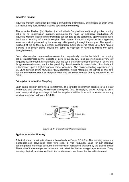
Each cable coupler contains a transformer. The toroidal transformer consists <strong>of</strong> a circular<br />
ferrite core and two coils, which share a magnetic field. By applying an AC voltage to an 8-<br />
turn primary winding, a voltage <strong>of</strong> half the amplitude will be induced in a 4-turn secondary<br />
winding, as shown in Figure 1.3.4.1b.<br />
Typical Inductive Mooring<br />
Figure 1.3.4.1 b: Transformer Operation Example<br />
A typical ocean mooring is shown schematically in Figure 1.3.4.1 c. The mooring cable is a<br />
plastic-jacketed galvanized steel wire rope, a type frequently used for non-inductive<br />
oceanographic moorings because <strong>of</strong> the corrosion resistance provided by the plastic jacket.<br />
The ends <strong>of</strong> the wire rope are terminated with steel thimbles or swaged eye terminals. Deep<br />
moorings typically employ synthetic line or stainless chain below the lowest instrument.<br />
28