Installation Manual Truck Edition V-500 Series - Thermo King
Installation Manual Truck Edition V-500 Series - Thermo King
Installation Manual Truck Edition V-500 Series - Thermo King

Create successful ePaper yourself
Turn your PDF publications into a flip-book with our unique Google optimized e-Paper software.
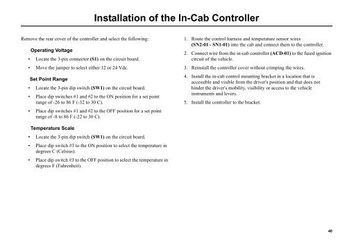
Remove the rear cover of the controller and select the following:<br />
Operating Voltage<br />
Locate the 3-pin connector (S1) on the circuit board.<br />
Move the jumper to select either 12 or 24 Vdc.<br />
Set Point Range<br />
Locate the 3-pin dip switch (SW1) on the circuit board.<br />
<strong>Installation</strong> of the In-Cab Controller<br />
Place dip switches #1 and #2 to the ON position for a set point<br />
range of -26 to 86 F (-32 to 30 C).<br />
Place dip switches #1 and #2 to the OFF position for a set point<br />
range of -8 to 86 F (-22 to 30 C).<br />
Temperature Scale<br />
Locate the 3-pin dip switch (SW1) on the circuit board.<br />
Place dip switch #3 to the ON position to select the temperature in<br />
degrees C (Celsius).<br />
Place dip switch #3 to the OFF position to select the temperature in<br />
degrees F (Fahrenheit).<br />
1. Route the control harness and temperature sensor wires<br />
(SN2-01 - SN1-01) into the cab and connect them to the controller.<br />
2. Connect wire from the in-cab controller (ACD-01) to the fused ignition<br />
circuit of the vehicle.<br />
3. Reinstall the controller cover without crimping the wires.<br />
4. Install the in-cab control mounting bracket in a location that is<br />
accessible and visible from the driver's position and that does not<br />
hinder the driver's mobility, visibility or access to the vehicle<br />
instruments and levers.<br />
5. Install the controller to the bracket.<br />
40