- Page 1 and 2: THE ELECTRONICS REVOLUTION Inventin
- Page 3 and 4: J.B. Williams The Electronics Revol
- Page 5 and 6: Contents Acknowledgments...........
- Page 7 and 8: Acknowledgments It would seem appro
- Page 9 and 10: List of Figures ix Fig. 11.1 Rise o
- Page 11 and 12: 1 Introduction On December 12, 1901
- Page 13 and 14: Introduction 3 The fundamental scie
- Page 15 and 16: 2 Missed Opportunities: The Beginni
- Page 17 and 18: Missed Opportunities: The Beginning
- Page 19 and 20: Missed Opportunities: The Beginning
- Page 21 and 22: Missed Opportunities: The Beginning
- Page 23 and 24: Missed Opportunities: The Beginning
- Page 25 and 26: 3 From Wireless to Radio An invento
- Page 27 and 28: From Wireless to Radio 17 No one to
- Page 29 and 30: From Wireless to Radio 19 Like ever
- Page 31 and 32: From Wireless to Radio 21 wave band
- Page 33 and 34: From Wireless to Radio 23 6. Advert
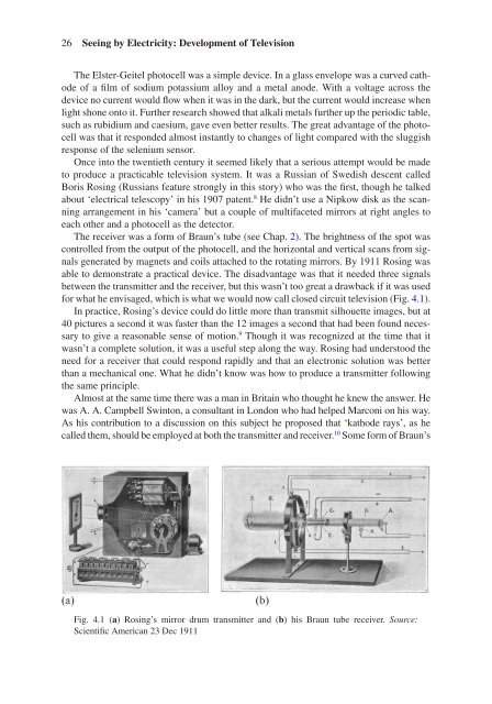
- Page 35: Seeing by Electricity: Development
- Page 39 and 40: Seeing by Electricity: Development
- Page 41 and 42: Seeing by Electricity: Development
- Page 43 and 44: Seeing by Electricity: Development
- Page 45 and 46: Seeing by Electricity: Development
- Page 47 and 48: 5 Seeing a Hundred Miles: Radar Fre
- Page 49 and 50: Seeing a Hundred Miles: Radar 39 ai
- Page 51 and 52: Seeing a Hundred Miles: Radar 41 co
- Page 53 and 54: Seeing a Hundred Miles: Radar 43 In
- Page 55 and 56: Seeing a Hundred Miles: Radar 45 NO
- Page 57 and 58: 6 The ‘Box’: Television Takes O
- Page 59 and 60: The ‘Box’: Television Takes Ove
- Page 61 and 62: The ‘Box’: Television Takes Ove
- Page 63 and 64: The ‘Box’: Television Takes Ove
- Page 65 and 66: The ‘Box’: Television Takes Ove
- Page 67 and 68: 7 Spinning Discs: Recorded Music My
- Page 69 and 70: hence not reproduce the sound corre
- Page 71 and 72: Spinning Discs: Recorded Music 61 T
- Page 73 and 74: Spinning Discs: Recorded Music 63 F
- Page 75 and 76: Spinning Discs: Recorded Music 65 t
- Page 77 and 78: Spinning Discs: Recorded Music 67 3
- Page 79 and 80: 8 The Crystal Triode: The Transisto
- Page 81 and 82: The Crystal Triode: The Transistor
- Page 83 and 84: The Crystal Triode: The Transistor
- Page 85 and 86: The Crystal Triode: The Transistor
- Page 87 and 88:
Despite attempts by Beckman to reso
- Page 89 and 90:
The Crystal Triode: The Transistor
- Page 91 and 92:
9 Pop Music: Youth Culture in the 1
- Page 93 and 94:
Pop Music: Youth Culture in the 195
- Page 95 and 96:
BBC TV, like its radio, wasn’t re
- Page 97 and 98:
10 From People to Machines: The Ris
- Page 99 and 100:
From People to Machines: The Rise o
- Page 101 and 102:
From People to Machines: The Rise o
- Page 103 and 104:
From People to Machines: The Rise o
- Page 105 and 106:
From People to Machines: The Rise o
- Page 107 and 108:
11 Chips into Everything: Integrate
- Page 109 and 110:
Chips into Everything: Integrated C
- Page 111 and 112:
Chips into Everything: Integrated C
- Page 113 and 114:
Chips into Everything: Integrated C
- Page 115 and 116:
Chips into Everything: Integrated C
- Page 117 and 118:
Chips into Everything: Integrated C
- Page 119 and 120:
From Signboards to Screens: Display
- Page 121 and 122:
From Signboards to Screens: Display
- Page 123 and 124:
From Signboards to Screens: Display
- Page 125 and 126:
From Signboards to Screens: Display
- Page 127 and 128:
From Signboards to Screens: Display
- Page 129 and 130:
Distributing Time: Clocks and Watch
- Page 131 and 132:
Distributing Time: Clocks and Watch
- Page 133 and 134:
Distributing Time: Clocks and Watch
- Page 135 and 136:
Distributing Time: Clocks and Watch
- Page 137 and 138:
From Desktop to Pocket: Calculators
- Page 139 and 140:
From Desktop to Pocket: Calculators
- Page 141 and 142:
From Desktop to Pocket: Calculators
- Page 143 and 144:
From Desktop to Pocket: Calculators
- Page 145 and 146:
From Desktop to Pocket: Calculators
- Page 147 and 148:
Shrinking Computers: Microprocessor
- Page 149 and 150:
Shrinking Computers: Microprocessor
- Page 151 and 152:
Shrinking Computers: Microprocessor
- Page 153 and 154:
Shrinking Computers: Microprocessor
- Page 155 and 156:
16 Instant Cooking: Microwave Ovens
- Page 157 and 158:
Instant Cooking: Microwave Ovens 14
- Page 159 and 160:
Instant Cooking: Microwave Ovens 14
- Page 161 and 162:
Instant Cooking: Microwave Ovens 15
- Page 163 and 164:
17 Essentials or Toys: Home Compute
- Page 165 and 166:
Essentials or Toys: Home Computers
- Page 167 and 168:
Essentials or Toys: Home Computers
- Page 169 and 170:
Essentials or Toys: Home Computers
- Page 171 and 172:
Essentials or Toys: Home Computers
- Page 173 and 174:
Computers Take Over the Workplace 1
- Page 175 and 176:
Computers Take Over the Workplace 1
- Page 177 and 178:
Computers Take Over the Workplace 1
- Page 179 and 180:
Computers Take Over the Workplace 1
- Page 181 and 182:
19 From Clerks to Xerography: Copie
- Page 183 and 184:
From Clerks to Xerography: Copiers
- Page 185 and 186:
From Clerks to Xerography: Copiers
- Page 187 and 188:
From Clerks to Xerography: Copiers
- Page 189 and 190:
From Clerks to Xerography: Copiers
- Page 191 and 192:
Shrinking the World: Communication
- Page 193 and 194:
Shrinking the World: Communication
- Page 195 and 196:
Shrinking the World: Communication
- Page 197 and 198:
Shrinking the World: Communication
- Page 199 and 200:
Shrinking the World: Communication
- Page 201 and 202:
Shrinking the World: Communication
- Page 203 and 204:
Shrinking the World: Communication
- Page 205 and 206:
Personal Communicators: Mobile Phon
- Page 207 and 208:
Personal Communicators: Mobile Phon
- Page 209 and 210:
Personal Communicators: Mobile Phon
- Page 211 and 212:
Personal Communicators: Mobile Phon
- Page 213 and 214:
Personal Communicators: Mobile Phon
- Page 215 and 216:
22 Going Online: The Internet The I
- Page 217 and 218:
Going Online: The Internet 207 A me
- Page 219 and 220:
Going Online: The Internet 209 Fig.
- Page 221 and 222:
Going Online: The Internet 211 To e
- Page 223 and 224:
Going Online: The Internet 213 The
- Page 225 and 226:
23 Glass to the Rescue: Fiber Optic
- Page 227 and 228:
Glass to the Rescue: Fiber Optics 2
- Page 229 and 230:
Glass to the Rescue: Fiber Optics 2
- Page 231 and 232:
Glass to the Rescue: Fiber Optics 2
- Page 233 and 234:
Glass to the Rescue: Fiber Optics 2
- Page 235 and 236:
Glass to the Rescue: Fiber Optics 2
- Page 237 and 238:
Towards Virtual Money: Cards, ATMs
- Page 239 and 240:
Towards Virtual Money: Cards, ATMs
- Page 241 and 242:
Towards Virtual Money: Cards, ATMs
- Page 243 and 244:
Towards Virtual Money: Cards, ATMs
- Page 245 and 246:
Saving TV Programmes: Video Recordi
- Page 247 and 248:
Saving TV Programmes: Video Recordi
- Page 249 and 250:
Saving TV Programmes: Video Recordi
- Page 251 and 252:
Saving TV Programmes: Video Recordi
- Page 253 and 254:
26 Electronics Invades Photography:
- Page 255 and 256:
Electronics Invades Photography: Di
- Page 257 and 258:
Electronics Invades Photography: Di
- Page 259 and 260:
Electronics Invades Photography: Di
- Page 261 and 262:
27 Seeing Inside the Body: Electron
- Page 263 and 264:
Seeing Inside the Body: Electronics
- Page 265 and 266:
Seeing Inside the Body: Electronics
- Page 267 and 268:
Seeing Inside the Body: Electronics
- Page 269 and 270:
Seeing Inside the Body: Electronics
- Page 271 and 272:
Knowing Where You Are: GPS 261 the
- Page 273 and 274:
Knowing Where You Are: GPS 263 syst
- Page 275 and 276:
Knowing Where You Are: GPS 265 slig
- Page 277 and 278:
Knowing Where You Are: GPS 267 of t
- Page 279 and 280:
Knowing Where You Are: GPS 269 2. W
- Page 281 and 282:
The Electronics Revolution 271 Fig.
- Page 283 and 284:
The Electronics Revolution 273 few
- Page 285 and 286:
Bibliography Addison, P. (1995). No
- Page 287 and 288:
Bibliography 277 Oxford Dictionary
- Page 289 and 290:
280 Index Brattain, W., 22, 71-74,
- Page 291 and 292:
282 Index Jobs, S., 94, 153, 162, 1
- Page 293:
284 Index Sony, 64, 65, 67, 68, 235