LGA/LCA/LHA - lennox
LGA/LCA/LHA - lennox
LGA/LCA/LHA - lennox

Create successful ePaper yourself
Turn your PDF publications into a flip-book with our unique Google optimized e-Paper software.
2−Indoor Blower Motor B3 (all units)<br />
All <strong>LGA</strong>/<strong>LCA</strong>/<strong>LHA</strong> units use three-phase single-speed blower<br />
motors. CFM adjustments are made by adjusting the motor<br />
pulley (sheave). Motors are equipped with sealed ball bearings.<br />
All motor specifications are listed in the tables on pages<br />
3, 5, and 6. Units may be equipped with motors manufactured<br />
by various manufacturers, therefore electrical FLA and LRA<br />
specifications will vary. See unit rating plate for information<br />
specific to your unit.<br />
OPERATION / ADJUSTMENT<br />
Blower Operation<br />
NOTE−The following is a generalized procedure and does<br />
not apply to all thermostat control systems.<br />
1− Blower operation is dependent on the thermostat control<br />
system option that has been installed in the <strong>LGA</strong>/<strong>LCA</strong>/<br />
<strong>LHA</strong> units. Refer to operation sequence of the control system<br />
installed for detailed descriptions of blower operation.<br />
2− Generally, blower operation is set at the thermostat fan<br />
switch. With the fan switch in �ON" position and the OCP<br />
input is �ON", the blower operates continuously. With<br />
the fan switch in �AUTO" position, the blower cycles<br />
with demand.<br />
3− In most cases, the blower and entire unit will be off when<br />
the system switch is in the �OFF" position. The only exception<br />
is immediately after a heating demand when the<br />
blower control keeps the blower on until all heat is extracted<br />
from the heat exchanger.<br />
Determining Unit Air Volume<br />
1− The following measurements must be made with a dry indoor<br />
coil. Run blower without cooling demand. Air filters<br />
must be in place when measurements are taken.<br />
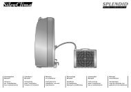
BLOWER MAY NEED TO BE<br />
REMOVED TO INSPECT<br />
HEAT EXCHANGER, REAR<br />
BLOWER BEARINGS, ETC.<br />
BLOWER ASSEMBLY<br />
SLIDING BASE<br />
LOOSEN (4) SCREWS TO<br />
ADJUST BELT TENSION<br />
PULLEY<br />
TO DECREASE AIR VOLUME<br />
TURN PULLEY COUNTERCLOCKWISE<br />
TO INCREASE AIR VOLUME<br />
LOOSEN ALLEN SCREW & TURN PULLEY<br />
CLOCKWISE<br />
BLOW-<br />
ER<br />
MOTOR<br />
FIGURE 14<br />
Page 46<br />
2− With all access panels in place, measure static pressure<br />
external to unit (from supply to return).<br />
3− Measure the indoor blower wheel RPM.<br />
4− Refer to blower table on page 10, use static pressure and<br />
RPM readings to determine unit air volume. Use<br />
blower tables on pages 11 and 12 when installing<br />
units with the optional accessories listed.<br />
5− The RPM can be adjusted at the motor pulley. Loosen Allen<br />
screw and turn adjustable pulley clockwise to increase<br />
RPM. Turn counterclockwise to decrease RPM. See figure<br />
14.<br />
Blower Belt Adjustment<br />
Proper pulley alignment and belt tension must be maintained<br />
for maximum belt life.<br />
NOTE−Tension new belt after 24−48 hours of operation.<br />
This will allow belts to stretch and seat in grooves.<br />
1− Loosen four screws securing blower motor to sliding base.<br />
See figure 14.<br />
2− To increase belt tension −<br />
Turn belt tension adjusting screw to the left, or counterclockwise,<br />
to tighten the belt. This increases the distance<br />
between the blower motor and the blower housing.<br />
To loosen belt tension −<br />
Turn the adjusting screw to the right, or clockwise to<br />
loosen belt tension.<br />
3− Tighten four screws securing blower motor to sliding<br />
base once adjustments have been made.<br />
BELT TENSION<br />
ADJUSTING<br />
SCREW<br />
ALLEN<br />
SCREW<br />
REMOVE SCREWS TO<br />
SLIDE BLOWER<br />
ASSEMBLY OUT OF UNIT<br />
TO INCREASE BELT TENSION<br />
1−Loosen four screws securing<br />
blower motor to sliding base.<br />
2−Turn adjusting screw to the left,<br />
or counterclockwise, to move<br />
the motor downward and tighten<br />
the belt.<br />
3−Tighten four screws.<br />
BLOWER<br />
WHEEL BRACK-<br />
ET