LGA/LCA/LHA - lennox
LGA/LCA/LHA - lennox
LGA/LCA/LHA - lennox

Create successful ePaper yourself
Turn your PDF publications into a flip-book with our unique Google optimized e-Paper software.
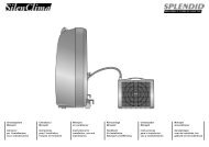
PRIMARY HIGH<br />
TEMP. LIMIT S10<br />
(FIRST HEAT SECTION)<br />
<strong>LGA</strong> HEATING COMPONENTS<br />
SECONDARY HIGH TEMP. LIMIT S21<br />
FIRST HEAT SECTION and S100<br />
(SECOND HEAT SECTION<br />
HIDDEN BEHIND BLOWERS)<br />
<strong>LGA</strong>240H − S10 AND S99<br />
LOCATED ON DRIP SHIELD BEHIND<br />
BLOWER HOUSING<br />
(PRODUCTION STARTING JULY 2004)<br />
COMBUSTION AIR BLOWER<br />
PROVE SWITCH S45<br />
(SECOND HEAT SECTION)<br />
PRIMARY HIGH<br />
TEMP. LIMIT S99<br />
(SECOND HEAT SECTION)<br />
access patch plate is located<br />
on condenser divider panel<br />
COMBUSTION AIR BLOWER<br />
PROVE SWITCH S18<br />
(FIRST HEAT SECTION)<br />
CONDENSER<br />
DIVIDER PANEL<br />
FIGURE 17<br />
D−Gas Heat Components (all <strong>LGA</strong> units)<br />
<strong>LGA</strong>156H units are available in 260,000 BTUH (76.2 kW)<br />
(standard gas heat only) and the <strong>LGA</strong>180/210/240/300S<br />
units are available in 260,000 BTUH (76.2 kW) (standard<br />
gas heat), or 470,000 BTUH (137.7 kW) (high gas heat)<br />
sizes. The <strong>LGA</strong>240H model is also available in 360,000<br />
BTUH (105.5 kW) (medium gas heat) All units are<br />
equipped with two identical gas heat sections (gas heat<br />
section one and gas heat section two). Black steel pipe will<br />
feed supply gas to both sections. Late model units will have<br />
a flexible connection instead of cast iron pipe. If for service<br />
the flexible connection must broken, hand tighten, then using<br />
a wrench turn additional 1/4 turn for metal to metal seal<br />
(do not over tighten).<br />
NOTE−Do not use thread sealing compound on flex pipe<br />
flare connections.<br />
1−Control Box Components<br />
A3, A12, A55, A58, T3, T13, K13 and K19<br />
WARNING<br />
DISCONNECT POWER BEFORE SERVICING. CONTROLS ARE<br />
NOT FIELD REPAIRABLE. UNSAFE OPERATION WILL RESULT. IF<br />
CONTROLS ARE INOPERABLE, SIMPLY REPLACE THE ENTIRE<br />
CONTROL.<br />
The main control box (see figure 4) houses the burner controls<br />
A3 and A12, main control module A55, gas valve (burner) control<br />
module A58, combustion air blower transformers T3 and<br />
T13, combustion air blower relay K13, and second heat section<br />
relay K19.<br />
Page 48<br />
Burner Ignition Control A3 and A12<br />
The ignition controls are located in the control box. Three different<br />
manufacturers’ (Fenwal, Johnson Controls, and RAM)<br />
controls are used in the <strong>LGA</strong> units. All three ignition controls<br />
operate the same.<br />
The ignition control provides three main functions: gas<br />
valve control, ignition, and flame sensing. The unit will<br />
usually ignite on the first attempt; however, the ignition attempt<br />
sequence provides three trials for ignition before<br />
locking out. The lockout time for the Johnson control is 5 minutes.<br />
The lockout time for the Fenwal control and RAM control<br />
is 1 hour. After lockout, the ignition control automatically resets<br />
and provides three more attempts at ignition. Manual<br />
reset after lockout requires breaking and remaking power to<br />
the ignition control. See figure 19 for a normal ignition sequence<br />
and figure 20 for the ignition attempt sequence<br />
with retrials (nominal timings given for simplicity). Specific<br />
timings for the ignition controls are shown in figure 21.<br />
TABLE 2<br />
Manufacturer LED Code Description<br />
Steady �ON" Normal<br />
RAM<br />
2 Flash Reset Mode<br />
Steady Flash Failure<br />
Steady �ON" Normal<br />
Johnson<br />
.5 sec on / 2.5<br />
sec off<br />
Reset Mode<br />
�OFF"<br />
No Power or Detected<br />
Failure<br />
Flame rectification sensing is used on all <strong>LGA</strong> units.<br />
Loss of flame during a heating cycle is indicated by an absence<br />
of flame signal (0 microamps). If this happens, the control<br />
will immediately restart the ignition sequence and then lock<br />
out if ignition is not gained after the third trial. See Sytems<br />
Service Checks section for flame current measurement.<br />
The control shuts off gas flow immediately in the event of a<br />
power failure. Upon restoration of gas and power, the control<br />
will restart the ignition sequence and continue until flame is<br />
established or system locks out.<br />
On a heating demand, the ignition control is energized by the<br />
main control module A55. The ignition control then allows 30<br />
to 40 seconds for the combustion air blower to vent exhaust<br />
gases from the burners. When the combustion air blower is<br />
purging the exhaust gases, the combustion air prove switch is<br />
closing proving that the combustion air blower is operating<br />
before allowing the ignition control to energize. When the<br />
combustion air prove switch is closed and the delay is over,<br />
the ignition control activates gas valve, the spark electrode<br />
and the flame sensing electrode. Sparking stops immediately<br />
after flame is sensed. The combustion air blower continues<br />
to operate throughout the heating demand. If the flame fails or<br />
if the burners do not ignite, the ignition control will attempt to<br />
ignite the burners up to two more times. If ignition cannot be<br />
obtained after the third attempt, the control will lock out. The<br />
ignition control is not adjustable.