LGA/LCA/LHA - lennox
LGA/LCA/LHA - lennox
LGA/LCA/LHA - lennox

You also want an ePaper? Increase the reach of your titles
YUMPU automatically turns print PDFs into web optimized ePapers that Google loves.
Service Literature<br />
Corp. 9525−L6<br />
Revised 10−2007<br />
<strong>LGA</strong> / <strong>LCA</strong> / <strong>LHA</strong> SERIES<br />
The <strong>LGA</strong> / <strong>LCA</strong> / <strong>LHA</strong> 13, 15, 17.5, 20 and 25 ton (46, 53, 62,<br />
70 and 88 kW) units are configure to order units (CTO) with a<br />
wide selection of factory installed options. The<br />
<strong>LGA</strong>180/210/240/300S gas/electric packaged rooftop units<br />
are available in 260,000 Btuh or 470,000 Btuh (76.2 kW or<br />
137.7 kW) heating inputs. The <strong>LGA</strong>156H is available in<br />
260,000 Btuh only. <strong>LGA</strong>240H is the only model available in<br />
360,000 BTUH (105.5 kW) Gas heat sections are designed<br />
with Lennox’ aluminized steel tube heat exchangers. The<br />
<strong>LCA</strong>156H/180/210/240/300S cooling packaged rooftop units<br />
are equipped with the same cooling sections as the<br />
<strong>LGA</strong>156H/180/210/240/300S units. Optional electric heat is<br />
factory−or field−installed in <strong>LCA</strong> units. Electric heat operates in<br />
single or multiple stages depending on the kW input size.<br />
15kW through 60kW heat sections are available for the<br />
<strong>LCA</strong>156H and <strong>LCA</strong>180 and 15kW through 90kW heat sections<br />
are available for the <strong>LCA</strong>210/240/300S. <strong>LGA</strong> and <strong>LCA</strong><br />
units have identical refrigerant circuits with 13, 15, 17.5, 20 or<br />
25 ton (46, 53, 62, 70 or 88 kW) cooling capacities. <strong>LGA</strong>/<br />
<strong>LCA</strong>156H/180 units utilize three compressors, while the <strong>LGA</strong>/<br />
<strong>LCA</strong>210,240 and 300S units utilize four compressors.<br />
The <strong>LGA</strong>/<strong>LCA</strong>240H4 is designed for R410A refrigerant. Operating<br />
pressures and pressure switch settings are higher<br />
than R22 charged units. Service equipment must be rated<br />
for R410A.<br />
The <strong>LHA</strong>180 and 240 packaged heat pump units are available<br />
in 188,000 Btuh through 220,000 Btuh (55.1 kW<br />
through 64.5 kW) heating outputs and 15 or 20−ton (52.8 or<br />
70.3 kW) cooling capacities. The <strong>LHA</strong>180/240 refrigerant<br />
systems utilize two compressors, two reversing valves, two<br />
accumulators, and other parts common to a heat pump. Optional<br />
auxiliary electric heat is factory−or field−installed in<br />
<strong>LHA</strong> units. Electric heat operates in single or multiple stages<br />
depending on the kW input size. 15kW through 60kW heat<br />
sections are available for the <strong>LHA</strong>180 and 15kW through<br />
90kW heat sections are available for the <strong>LHA</strong>240.<br />
If the unit must be lifted for service, rig unit by attaching four<br />
cables to the holes located in the unit base rail (two holes at<br />
each corner). Refer to the installation instructions for the proper<br />
rigging technique.<br />
Information contained in this manual is intended for use by<br />
qualified service technicians only. All specifications are subject<br />
to change. Procedures outlined in this manual are presented<br />
as a recommendation only and do not supersede or<br />
replace local or state codes.<br />
Page 1<br />
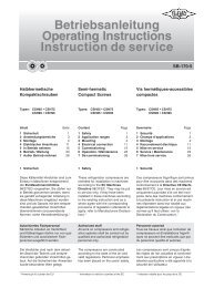
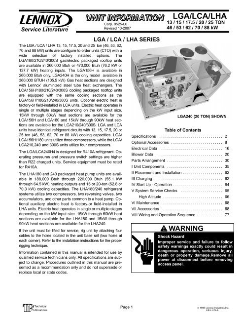
<strong>LGA</strong>/<strong>LCA</strong>/<strong>LHA</strong><br />
13 / 15 / 17.5 / 20 / 25 TON<br />
46 / 53 / 62 / 70 / 88 kW<br />
<strong>LGA</strong>240 (20 TON) SHOWN<br />
Table of Contents<br />
Specifications . . . . . . . . . . . . . . . . . . . . . . . . . . . . . . . . . 2<br />
Optional Accessories . . . . . . . . . . . . . . . . . . . . . . . . . . 8<br />
Electrical Data . . . . . . . . . . . . . . . . . . . . . . . . . . . . . . . . 16<br />
Blower Data . . . . . . . . . . . . . . . . . . . . . . . . . . . . . . . . . . 20<br />
Parts Arrangement . . . . . . . . . . . . . . . . . . . . . . . . . . . . 30<br />
I Unit Components . . . . . . . . . . . . . . . . . . . . . . . . . . . . 35<br />
II Placement and Installation . . . . . . . . . . . . . . . . . . . . 62<br />
III Charging . . . . . . . . . . . . . . . . . . . . . . . . . . . . . . . . . . . 62<br />
IV Start Up − Operation . . . . . . . . . . . . . . . . . . . . . . . . . 64<br />
V System Service Checks . . . . . . . . . . . . . . . . . . . . . 65<br />
High Altitude . . . . . . . . . . . . . . . . . . . . . . . . . . . . . . 66<br />
VI Maintenance . . . . . . . . . . . . . . . . . . . . . . . . . . . . . . . 68<br />
VII Accessories . . . . . . . . . . . . . . . . . . . . . . . . . . . . . . 68<br />
VIII Wiring and Operation Sequence . . . . . . . . . . . . . 77<br />
WARNING<br />
Shock Hazard<br />
Improper service and failure to follow<br />
safety warnings exactly could result in<br />
dangerous operation, seriuous injury,<br />
death or property damage.Remove all<br />
power at disconnect before removing<br />
access panel.<br />
© 1999 Lennox Industries Inc.<br />
Litho U.S.A.
SPECIFICATIONS − <strong>LCA</strong>/<strong>LGA</strong> 156/180<br />
Model No. <strong>LCA</strong>/<strong>LGA</strong>156H <strong>LCA</strong>/<strong>LGA</strong>180S <strong>LCA</strong>/<strong>LGA</strong>180H<br />
Efficiency Type High (H) Standard (S) High (H)<br />
Gross Cooling Capacity − Btuh (kW) 155,000 (45.4) 186,000 (54.5) 188,000 (55.1)<br />
Cooling<br />
Ratings<br />
�Net Cooling Capacity − Btuh (kW)<br />
Total Unit Power (kW)<br />
�EER (Btuh/Watt)<br />
150,000 (44.0)<br />
13.0<br />
11.5<br />
180,000 (52.7)<br />
19.6<br />
9.2<br />
182,000 (53.3)<br />
15.8<br />
11.5<br />
�Integrated Part Load Value (Btuh/Watt) 12.6 10.0 12.5<br />
Circuit 1 11 lbs. 0 oz. (4.99 kg)<br />
9 lbs. 0 oz.<br />
(4.08 kg)<br />
11 lbs. 0 oz. (4.99 kg)<br />
Humiditrol Units 13 lbs. 8<br />
oz. (6.12 kg)<br />
Refrigerant Charge<br />
Furnished (HCFC-22)<br />
Circuit 2 11 lbs.. 0 oz. (4.99 kg)<br />
9 lbs. 0 oz.<br />
(4.08 kg)<br />
11 lbs. 0 oz. (4.99 kg)<br />
Humiditrol Units 13 lbs. 8<br />
oz. (6.12 kg)<br />
Circuit 3 11 lbs. 0 oz. (4.99 kg)<br />
9 lbs. 0 oz.<br />
(4.08 kg)<br />
11 lbs. 0 oz. (4.99 kg)<br />
Humiditrol Units 11 lbs. 0<br />
oz. (4.99 kg)<br />
TTwo o Stage<br />
Heating Heating<br />
Capacity<br />
(Natural (Natural or<br />
LPG/ProLPG/Propane p Gas<br />
(at Sea<br />
Level)<br />
Model No.<br />
Heat Input Type<br />
Input (low) � Btuh (kW)<br />
Output (low) � Btuh (kW)<br />
Input (High) � Btuh (kW)<br />
Output (High) � Btuh (kW)<br />
A.G.A./C.G.A. Thermal Efficiency<br />
<strong>LGA</strong>156<br />
Low (L) Standard (S)<br />
169,000 (49.5) 169,000 (49.5)<br />
135,000 (39.6) 135,000 (39.6)<br />
− − − − 260,000 (76.2)<br />
− − − − 208,000 (60.9)<br />
Low (L)<br />
169,000 (49.5)<br />
135,000 (39.6)<br />
− − − −<br />
− − − −<br />
80.0%<br />
<strong>LGA</strong>180<br />
Standard (S)<br />
169,000 (49.5)<br />
135,000 (39.6)<br />
260,000 (76.2)<br />
208,000 (60.9)<br />
High (H)<br />
305,000 (89.4)<br />
244,000 (71.5)<br />
470,000 (137.7)<br />
376,000 (110.2)<br />
Gas Supply Connections npt � in. −Natural l or LPG/Propane 1<br />
Recommended Gas<br />
Supply Pressure − wc. in. (kPa)<br />
Natural<br />
LPG/Propane<br />
7 (1.7)<br />
11 (2.7)<br />
Blower�wheel�nominal�dia.�x�width���in.�(mm) (2) 15 x 15 (381 x 381)<br />
Nominal motor output − hp (kW) 2 (1.5) − − − −<br />
2h 2 hp (15kW) (1.5 kW)<br />
�Motor �Motor &<br />
Drive<br />
Max. usable motor output − hp (kW)<br />
Voltage & phase<br />
(Drive kit #) RPM range<br />
2.30 (1.7)<br />
208/230v, 460v 575v-3ph<br />
(A) 535−725<br />
− − − −<br />
− − − −<br />
− − − −<br />
Nominal motor output − hp (kW) 3 (2.2)<br />
Evaporator<br />
Blower<br />
and<br />
Di Drive<br />
Selection Selection<br />
3h 3 hp (22kW) (2.2 kW)<br />
�Motor �Motor &<br />
Drives<br />
5h 5 hp (37kW) (3.7 kW)<br />
�Motor �Motor &<br />
Drives<br />
Max. usable motor output − hp (kW)<br />
Voltage & phase<br />
(Drive kit #) RPM range<br />
Nominal motor horsepower (kW)<br />
Max. usable motor output − hp (kW)<br />
Voltage & phase<br />
(Drive kit #) RPM range<br />
3.45 (2.6)<br />
208/230v, 460v or 575v-3ph<br />
(A) 535−725 or (1 or 2) 685 � 865<br />
5 (3.7)<br />
5.75 (4.3)<br />
208/230v, 460v or 575v-3ph<br />
(2) 685 − 865, (3) 850 − 1045 or (4) 945 − 1185<br />
Nominal motor output − hp (kW) − − − − 7.5 (5.6)<br />
75h 7.5 hp (56kW) (5.6 kW)<br />
�Motor �Motor &<br />
Drive<br />
Max. usable motor output − hp (kW)<br />
Voltage & phase<br />
(Drive kit #) RPM range<br />
− − − −<br />
− − − −<br />
− − − −<br />
8.63 (6.4)<br />
208/230v, 460v or 575v-3ph<br />
(5) 945 � 1185<br />
Net face area � sq. ft. (m2 ) 22.3 (2.07) total<br />
EEvaporator aporator<br />
Coil<br />
Tube diameter � in. (mm) & No. of rows<br />
Fins per inch (m)<br />
Drain connection no. & size � in. (mm) fpt<br />
3/8 (9.5) � 3<br />
14 (551)<br />
(1) 1 (25.4)<br />
Expansion device type Balanced Port Thermostatic Expansion Valve, removeable power head<br />
Condenser Net face area � sq. ft. (m2 Condenser<br />
Coil<br />
)<br />
Tube diameter � in. (mm) & No. of rows<br />
Fins per inch (m)<br />
56.5 (5.25) total<br />
3/8 (9.5) � 1 (standard efficiency) / 3/8 (9.5) � 2 (high efficiency)<br />
20 (787) standard & 16 (630) high<br />
Diameter � in. (mm) & No. of blades (4) 24 (610) � 3<br />
Condenser<br />
Fans<br />
Total Air volume � cfm (L/s)<br />
Motor horsepower (W)<br />
Motor rpm<br />
15,850 (7480) standard efficiency � 15,700 (7410) high efficiency<br />
(4) 1/3 (249)<br />
1075<br />
Total Motor watts 1370 standard efficiency � 1380 high efficiency<br />
Filters<br />
(furnished)<br />
Type of filter<br />
No. and size � in. (mm)<br />
Disposable, commercial grade, pleated<br />
(6) 24 x 24 x 2 (610 x 610 x 51)<br />
Electrical characteristics 208/230v, 460v or 575v � 60 hertz � 3 phase<br />
�Using total air volume and system static pressure requirements determine from blower performance tables rpm and motor output required. Maximum usable output of motors<br />
furnished by Lennox are shown. In Canada, nominal motor output is also maximum usable motor output. If motors of comparable output are used, be sure to keep within the service<br />
factor limitations outlined on the motor nameplate.<br />
�Rated in accordance with ARI Standard 340/360 and certified to ARI; 95�F (35�C) outdoor air temperature and 80�F (27�C) db/67�F (19�C) wb entering evaporator air; minimum<br />
external duct static pressure. Integrated Part Load Value tested at 80�F (27�C) outdoor air temperature.<br />
NOTE � ARI capacity is net and includes evaporator blower motor heat deduction. Gross capacity does not include evaporator blower motor heat deduction.<br />
Page 2
Cooling<br />
Ratings<br />
Refrigerant Charge<br />
Furnished (HCFC-22)<br />
SPECIFICATIONS − <strong>LCA</strong>/<strong>LGA</strong>−210<br />
Model No. <strong>LCA</strong>/<strong>LGA</strong>210S <strong>LCA</strong>/<strong>LGA</strong>210H<br />
Efficiency Type Standard (S) High (H)<br />
Gross Cooling Capacity − Btuh (kW) 212,000 (62.1) 218,000 (63.9)<br />
�Net Cooling Capacity − Btuh (kW) 204,000 (59.8) 210,000 (61.5)<br />
Total Unit Power (kW) 22.7 18.8<br />
�EER (Btuh/Watt) 9.0 11.2<br />
�Integrated Part Load Value (Btuh/Watt) 9.5 11.5<br />
Circuit 1<br />
Circuit 2<br />
Circuit 3<br />
Circuit 4<br />
Page 3<br />
7 lbs. 8 oz.<br />
(3.4 kg)<br />
7 lbs. 8 oz.<br />
(3.4 kg)<br />
7 lbs. 8 oz.<br />
(3.4 kg)<br />
7 lbs. 8 oz.<br />
(3.4 kg)<br />
Model No. <strong>LGA</strong>210<br />
11 lbs. 0 oz. (4.99 kg)<br />
Humiditrol Unit 13 lbs. 0 oz. (5.90 kg)<br />
11 lbs. 0 oz. (4.99 kg)<br />
Humiditrol Unit 13 lbs. 0 oz. (5.90 kg)<br />
11 lbs. 0 oz. (4.99 kg)<br />
Humiditrol Units 11 lbs. 0 oz. (4.99 kg)<br />
11 lbs. 0 oz. (4.99 kg)<br />
Humiditrol Units 11lbs. 0 oz. (4.99 kg)<br />
Heat Input Type Standard (S) High (H)<br />
TTwo St Stage<br />
Heating Heating Capacity<br />
(Natural ( or<br />
LPG/Propane Gas<br />
(at Sea Level)<br />
Input (low) � Btuh (kW)<br />
Output (low) � Btuh (kW)<br />
Input (High) � Btuh (kW)<br />
169,000 (49.5)<br />
135,000 (39.6)<br />
260,000 (76.2)<br />
305,000 (89.4)<br />
244,000 (71.5)<br />
470,000 (137.7)<br />
Output (High) � Btuh (kW) 208,000 (60.9) 376,000 (110.2)<br />
A.G.A./C.G.A. Thermal Efficiency 80.0%<br />
Gas Supply Connections npt � in. −Natural l or LPG/Propane 1<br />
Recommended Gas<br />
Supply Pressure − wc. in. (kPa)<br />
Natural<br />
LPG/Propane<br />
7 (1.7)<br />
11 (2.7)<br />
Blower�wheel�nominal�dia.�x�width���in.�(mm) (2) 15 x 15 (381 x 381)<br />
Nominal motor output − hp (kW) 3 (2.2)<br />
3 hp (2.2 kW)<br />
�Motor �Motor &<br />
Drives<br />
Max. usable motor output − hp (kW)<br />
Voltage & phase<br />
3.45 (2.6)<br />
208/230v, 460v or 575v-3ph<br />
(Drive kit #) RPM range (A) 535−725 or (1 or 2) 685 � 865<br />
EEvaporator t<br />
Blower Blower<br />
and<br />
Di Drive<br />
Selection<br />
5 hp (3.7 kW)<br />
�Motor �Motor &<br />
Drives<br />
Nominal motor horsepower (kW)<br />
Max. usable motor output − hp (kW)<br />
Voltage & phase<br />
(Drive kit #) RPM range<br />
5 (3.7)<br />
5.75 (4.3)<br />
208/230v, 460v or 575v-3ph<br />
(2) 685 − 865, (3) 850 − 1045 or (4) 945 − 1185<br />
Nominal motor output − hp (kW) 7.5 (5.6)<br />
7.5 hp (5.6 kW)<br />
�Motor �Motor &<br />
Drive<br />
Max. usable motor output − hp (kW)<br />
Voltage & phase<br />
8.63 (6.4)<br />
208/230v, 460v or 575v-3ph<br />
(Drive kit #) RPM range (5) 945 � 1185<br />
Net face area � sq. ft. (m2 ) 22.3 (2.07) total<br />
Tube diameter � in. (mm) & No. of rows<br />
3/8 (9.5) � 3 (standard efficiency) / 3/8 (9.5) � 4 (high efficiency)<br />
Evaporator p Coil Fins per inch (m) 14 (551)<br />
Drain connection no. & size � in. (mm) fpt (1) 1 (25.4)<br />
Expansion device type<br />
Balanced Port Thermostatic Expansion Valve, removeable<br />
power head<br />
Net face area � sq. ft. (m2 ) 56.5 (5.25) total<br />
Condenser Coil Tube diameter � in. (mm) & No. of rows<br />
3/8 (9.5) � 1 (standard efficiency) / 3/8 (9.5) � 2 (high efficiency)<br />
Fins per inch (m) 20 (787) standard & 16 (630) high<br />
Diameter � in. (mm) & No. of blades (4) 24 (610) � 3<br />
Condenser<br />
Fans<br />
Total Air volume � cfm (L/s)<br />
Motor horsepower (W)<br />
15,850 (7480) standard efficiency � 15,700 (7410) high efficiency<br />
(4) 1/3 (249)<br />
Motor rpm 1075<br />
Total Motor watts 1370 standard efficiency � 1380 high efficiency<br />
Filters<br />
(furnished)<br />
Type of filter<br />
No. and size � in. (mm)<br />
Disposable, commercial grade, pleated<br />
(6) 24 x 24 x 2 (610 x 610 x 51)<br />
Electrical characteristics 208/230v, 460v or 575v � 60 hertz � 3 phase<br />
�Using total air volume and system static pressure requirements determine from blower performance tables rpm and motor output required. Maximum usable output of motors<br />
furnished by Lennox are shown. In Canada, nominal motor output is also maximum usable motor output. If motors of comparable output are used, be sure to keep within the service<br />
factor limitations outlined on the motor nameplate.<br />
�Rated in accordance with ARI Standard 340/360 and certified to ARI; 95�F (35�C) outdoor air temperature and 80�F (27�C) db/67�F (19�C) wb entering evaporator air; minimum<br />
external duct static pressure. Integrated Part Load Value tested at 80�F (27�C) outdoor air temperature.<br />
NOTE � ARI capacity is net and includes evaporator blower motor heat deduction. Gross capacity does not include evaporator blower motor heat deduction.
SPECIFICATIONS − <strong>LCA</strong>/<strong>LGA</strong> 240/300<br />
Model No. <strong>LCA</strong>/<strong>LGA</strong>240S �<strong>LCA</strong>/<strong>LGA</strong>300S<br />
Efficiency Type Standard (S) Standard (S)<br />
Gross Cooling Capacity � Btuh (kW) 248,000 (72.7) 301,600 (88.4)<br />
Cooling<br />
Ratings g<br />
�Net Cooling Capacity � Btuh (kW)<br />
Total Unit Power (kW)<br />
238,000 (69.7)<br />
26.4<br />
�284,000 (83.3)<br />
31.5<br />
�EER (Btuh/Watt) 9.0 �9.0<br />
�Integrated Part Load Value (Btuh/Watt) 10.0 �9.5<br />
Refrigerant Charge<br />
Furnished (R−22)<br />
Refrigerant Charge<br />
Furnished (R−410A)<br />
Refrigerant Charge<br />
Furnished (R−22)<br />
with Humiditrol option<br />
Circuit 1<br />
Circuit 2<br />
Circuit 3<br />
Circuit 4<br />
Circuit 1<br />
Circuit 2<br />
Circuit 3<br />
Circuit 4<br />
Circuit 1<br />
Circuit 2<br />
Circuit 3<br />
Circuit 4<br />
10 lbs. 0 oz. (4.54 kg)<br />
10 lbs. 0 oz. (4.54 kg)<br />
10 lbs. 0 oz. (4.54 kg)<br />
10 lbs. 0 oz. (4.54 kg)<br />
11 lbs. 4 oz. (5.10 kg)<br />
11 lbs. 4 oz. (5.10 kg)<br />
11 lbs. 4 oz. (5.10 kg)<br />
11 lbs. 4 oz. (5.10 kg)<br />
N/A N/A<br />
N/A N/A<br />
Model No. <strong>LGA</strong>240 <strong>LGA</strong>300<br />
Two Stage<br />
Heating<br />
CCapacity p iy<br />
Natural or<br />
Propane<br />
Gas at<br />
sea level)<br />
Heat Input Type<br />
Input (low) � Btuh (kW)<br />
Output (low) � Btuh (kW)<br />
Input (High) � Btuh (kW)<br />
Output (High) � Btuh (kW)<br />
Standard (S)<br />
169,000 (49.5)<br />
135,000 (39.6)<br />
260,000 (76.2)<br />
208,000 (60.9)<br />
Standard (S)<br />
169,000 (49.5)<br />
135,000 (39.6)<br />
260,000 (76.2)<br />
208,000 (60.9)<br />
High (H)<br />
305,000 (89.4)<br />
244,000 (71.5)<br />
470,000<br />
(137.7)<br />
376,000<br />
(110.2)<br />
A.G.A./C.G.A. Thermal Efficiency 80.0%<br />
Gas Supply<br />
Connections npt � in.<br />
Natural<br />
LPG/Propane<br />
1<br />
1<br />
Recommended Gas<br />
Supply Pressure � wc. wc in. in<br />
(kPa)<br />
Natural<br />
LPG/Propane<br />
7 (1.7)<br />
11 (2.7)<br />
Blower�wheel�nominal�dia.�x�width���in.�(mm) (2) 15 x 15 (381 x 381)<br />
3hp 3 hp<br />
(2.2 (2.2 kW)<br />
�Motor � &<br />
Drives<br />
Nominal motor output � hp (kW)<br />
Max. usable motor output � hp (kW)<br />
Voltage & phase<br />
(Drive kit #) RPM range<br />
3 (2.2)<br />
3.45 (2.6)<br />
208/230v, 460v or 575v-3ph<br />
(1 or 2) 685 � 865<br />
− − − −<br />
− − − −<br />
− − − −<br />
− − − −<br />
Evaporator<br />
Blower<br />
and<br />
Di Drive<br />
Selection<br />
5hp 5 hp<br />
(3.7 kW)<br />
�Motor � &<br />
Drives<br />
75hp 7.5 hp<br />
(5.6 kW)<br />
�Motor � &<br />
Drive<br />
Nominal motor output � hp (kW)<br />
Max. usable motor output � hp (kW)<br />
Voltage & phase<br />
(Drive kit #) RPM range<br />
Nominal motor horsepower (kW)<br />
Max. usable motor output � hp (kW)<br />
Voltage & phase<br />
(Drive kit #) RPM range<br />
5 (3.7)<br />
5.75 (4.3)<br />
208/230v, 460v or 575v-3ph<br />
(2) 685 − 865, (3) 850 − 1045 or (4) 945 − 1185<br />
7.5 (5.6)<br />
8.63 (6.4)<br />
208/230v, 460v or 575v-3ph<br />
(5) 945 � 1185<br />
10 hp<br />
(7.5 kW)<br />
�Motor � &<br />
Drive<br />
Nominal motor horsepower (kW)<br />
Max. usable motor output � hp (kW)<br />
Voltage & phase<br />
(Drive kit #) RPM range<br />
10 hp (7.5)<br />
11.5 (8.6)<br />
208/230v, 460v or 575v-3ph<br />
(6) 1045−1285 rpm (8) 1135−1365)<br />
Net face area � sq. ft. (m<br />
Page 4<br />
2 ) 22.3 (2.07) total<br />
Evaporator p<br />
Coil<br />
Tube diameter � in. (mm) & No. of rows<br />
Fins per inch (m)<br />
3/8 (9.5) � 3 (Standard Efficiency)<br />
3/8 (9.5) � 4 (High Efficiency)<br />
14 (551)<br />
3/8 (9.5) � 4<br />
Drain connection no. & size � in. (mm) fpt (1) 1 (25.4)<br />
Expansion device type Balanced Port Thermostatic Expansion Valve, removeable power head<br />
Condenser Net face area � sq. ft. (m2 Condenser<br />
Coil<br />
)<br />
Tube diameter � in. (mm) & No. of rows<br />
Fins per inch (m)<br />
56.5 (5.25) total<br />
3/8 (9.5) � 2<br />
20 (787)<br />
Diameter � in. (mm) & No. of blades (4) 24 (610) � 3<br />
Condenser<br />
Fans<br />
Total Air volume � cfm (L/s)<br />
Motor horsepower (W)<br />
Motor rpm<br />
15,450 (7290)<br />
(4) 1/3 (249)<br />
1075<br />
16,000 (7550)<br />
(4) 1/2 (373)<br />
Total Motor watts 1395 1800<br />
Filters<br />
(furnished)<br />
Type of filter<br />
No. and size � in. (mm)<br />
Disposable, commercial grade, pleated<br />
(6) 24 x 24 x 2 (610 x 610 x 51)<br />
Electrical characteristics 208/230v, 460v or 575v � 60 hertz � 3 phase<br />
�Using total air volume and system static pressure requirements determine from blower performance tables rpm and motor output required. Maximum usable output of motors furnished by Lennox are<br />
shown. In Canada, nominal motor output is also maximum usable motor output. If motors of comparable output are used, be sure to keep within the service factor limitations outlined on the motor nameplate.<br />
�Rated in accordance with ARI Standard 340/360 and certified to ARI; 95�F (35�C) outdoor air temperature and 80�F (27�C) db/67�F (19�C) wb entering evaporator air; minimum external duct static<br />
pressure. Integrated Part Load Value tested at 80�F (27�C) outdoor air temperature. �Tested at conditions included in ARI Standard 340/360.<br />
NOTE � ARI capacity is net and includes evaporator blower motor heat deduction. Gross capacity does not include evaporator blower motor heat deduction.
SPECIFICATIONS − <strong>LCA</strong>/<strong>LGA</strong> 240H<br />
General<br />
DData t<br />
Nominal Tonnage (kW)<br />
Model No.<br />
20 Ton<br />
<strong>LCA</strong>/<strong>LGA</strong>240H2B R−22 − <strong>LCA</strong>/<strong>LGA</strong>240H4B R−410A − *<strong>LCA</strong>−5 &<strong>LGA</strong>−6 R410A<br />
Efficiency Type High<br />
Cooling<br />
PPerformance f<br />
Gross Cooling Capacity − Btuh (kW)<br />
1 Net Cooling Capacity − Btuh (kW)<br />
252,000 (73.8) − 254,000 (74.4), * 240,000 (70.32)<br />
242,000 (70.9) − 244,000 (71.5), * 230,000 (67.40)<br />
ARI Rated Air Flow − cfm (L/s) 7500 (3540)<br />
Total Unit Power (kW) 22.0 − 23.2, * 20.9<br />
1 EER (Btuh/Watt) 11.0 − 10.5, *11.0<br />
2 Integrated Part Load Value (Btuh/Watt) 11.8 − 11.5, *12.0<br />
Refrigerant Charge<br />
FFurnished i h d RR-22 22 −R410A R410A<br />
Circuit 1<br />
Circuit 2<br />
11 lbs. 4 oz. (5.10 kg) − 12 lbs 0 oz (5.44 kg), *10 lbs. 8 oz.<br />
11 lbs. 4 oz. (5.10 kg) − 12 lbs 0 oz (5.44 kg), *10 lbs. 8 oz.<br />
Circuit 3 11 lbs. 4 oz. (5.10 kg) − 12 lbs 0 oz (5.44 kg), *10 lbs. 8 oz.<br />
Circuit 4 11 lbs. 4 oz. (5.10 kg) − 12 lbs 0 oz (5.44 kg), *10 lbs. oz<br />
Cooling<br />
Performance Performance<br />
Refrigerant Charge<br />
Furnished R-22 −R410A<br />
with Humiditrol Option<br />
Circuit 1<br />
Circuit 2<br />
12 lbs. 4 oz. (5.56 kg) − 13 lbs 0 oz (5.90 kg), * 11 lbs. 8 oz.<br />
12 lbs. 4 oz. (5.56 kg) − 13 lbs 0 oz (5.90 kg), *11 lbs. oz.<br />
Circuit 3 11 lbs. 4 oz. (5.10 kg) − 12 lbs 0 oz (5.44 kg), * 10 lbs. 8 oz.<br />
Circuit 4 11 lbs. 4 oz. (5.10 kg) − 12 lbs 0 oz (5.44 kg), 10 lbs. 8 oz.<br />
Gas Heating<br />
Performance<br />
Heat Input Type Standard<br />
2 Stage<br />
Medium<br />
2 Stage<br />
High<br />
2 Stage<br />
Input − Btuh (kW) First Stage 169,000 (49.5) 234,000 (68.6) 312,000 (91.4)<br />
Second Stage 260,000 (76.2) 360,000 (105.5) 480,000 (140.6)<br />
Output − Btuh (kW) Second Stage 208,000 (60.9) 288,000 (84.4) 384,000 (112.5)<br />
CSA Thermal Efficiency 80.0%<br />
Gas Supply Connections 1 in.<br />
Recommended Gas Supply Pressure Natural 7 in. w.g. (1.7 kPa)<br />
LPG/Propane 11 in. w.g. (2.7 kPa)<br />
Compressor Type (no.) Scroll (4)<br />
Condenser Net face area − sq. ft. (m2 Condenser<br />
) total 56.5 (5.25)<br />
Coils<br />
Tube diameter − in. (mm) 3/8 (9.5)<br />
Number of rows 2<br />
Fins per inch (m) 20 (787)<br />
Condenser<br />
Motor horsepower (W) (4) 1/3 (249)<br />
Fans<br />
Motor rpm 1075<br />
Total Motor watts 1395<br />
Diameter − in. (mm) (4) 24 (610)<br />
Number of blades 3<br />
Total Air volume − cfm (L/s) 15,450 (7290)<br />
Evaporator Net face area − sq. ft. (m2 Evaporator<br />
) total 22.3 (2.07)<br />
Coils<br />
Tube diameter − in. (mm) 3/8 (9.5)<br />
Number of rows 4<br />
Fins per inch (m) 14 (551)<br />
Condensate Drain − number and size (1) 1 in. NPT coupling<br />
Expansion device type Balanced Port Thermostatic Expansion Valve, removeable power head<br />
3 Indoor<br />
Nominal motor output 5 hp (3.7 kW) − 7.5 hp (5.6 kW) − 10 hp (7.5 kW)<br />
Blower and<br />
Max. usable motor output (US Only) 5.75 hp (4.3 kW) − 8.63 hp (6.4 kW) − 11.5 hp (8.6 kW)<br />
Di Drive<br />
Selection<br />
Motor − Drive kit 5 hp<br />
kit #2 − 685 − 865 rpm<br />
kit #3 − 850 − 1045 rpm<br />
kit #4 945 − 1185 rpm<br />
7.5 hp<br />
kit #5 − 945 − 1185 rpm<br />
kit #6 − 1045 − 1285 rpm<br />
kit #7 − 850 − 1045 rpm<br />
10 hp<br />
kit #6 − 1045−1285 rpm<br />
kit #8 − 1135−1365 rpm<br />
Blower�wheel�nominal�dia.�x�width (2) 15 x 15 in. (381 x 381 mm)<br />
Filters Type of filter Disposable<br />
Number and size − in. (mm) (6) 24 x 24 x 2 (610x610x51)<br />
Electrical characteristics 208/230V, 460V or 575V − 60 hertz − 3 phase<br />
NOTE − Net capacity includes evaporator blower motor heat deduction. Gross capacity does not include evaporator blower motor heat deduction.<br />
1 Certified in accordance with the ULE certification program, which is based on ARI Standard 340/360; 95�F (35�C) outdoor air temperature and 80�F (27�C) db/67�F<br />
(19�C) wb entering evaporator air; minimum external duct static pressure.<br />
2 Integrated Part Load Value tested at 80�F (27�C) outdoor air temperature.<br />
3 Using total air volume and system static pressure requirements determine from blower performance tables rpm and motor output required. Maximum usable output of<br />
motors furnished by Lennox are shown. In Canada, nominal motor output is also maximum usable motor output. If motors of comparable output are used, be sure to keep<br />
within the service factor limitations outlined on the motor nameplate.<br />
Page 5
SPECIFICATIONS − <strong>LHA</strong> 180/240<br />
Units with Reciprocating Compressors<br />
Model No. <strong>LHA</strong>180H <strong>LHA</strong>240H<br />
Efficiency Type High (H) High (H)<br />
Gross Cooling Capacity � Btuh (kW) 185,000 (54.2) 233,000 (68.3)<br />
Cooling<br />
�Net Cooling Capacity � Btuh (kW) 180,000 (52.7) 226,000 (66.2)<br />
Ratings Total Unit Power (kW) 18.0 21.5<br />
High<br />
Temperature p<br />
Heating Ratings<br />
Low<br />
Temperature p<br />
Heating Ratings<br />
Refrigerant<br />
Charge<br />
Furnished<br />
(HCFC-22)<br />
Indoor Coil Blower<br />
and and<br />
Drive Selection<br />
�EER (Btuh/Watt) 10.0 10.5<br />
�Integrated Part Load Value (Btuh/Watt) 11.2 11.5<br />
*Total Heating Capacity � Btuh (kW) 188,000 (55.1) 220,000 (64.5)<br />
*Total Unit Power (kW) 16.7 20.2<br />
*C.O.P. 3.3 3.2<br />
*Total Heating Capacity � Btuh (kW) 108,000 (31.6) 118,000 (34.6)<br />
*Total Unit Power (kW) 13.2 15.0<br />
*C.O.P. 2.4 2.3<br />
Circuit 1 24 lbs. 8 oz. (11.11 kg) 26 lbs. 0 oz. (11.79 kg)<br />
Circuit 2 24 lbs. 8 oz. (11.11 kg) 26 lbs. 0 oz. (11.79 kg)<br />
Blower�wheel�nominal�dia.�x�width���in.�(mm) (2) 15 x 15 (381 x 381)<br />
Nominal motor output � hp (kW) 3 (2.2)<br />
3 hp (2.2 kW)<br />
�Motor �Motor &<br />
Drives Drives<br />
Max. usable motor output � hp (kW)<br />
Voltage & phase<br />
3.45 (2.6)<br />
208/230v, 460v or 575v-3ph<br />
(Drive kit #) RPM range (1 or 2) 685 � 865<br />
Nominal motor horsepower (kW) 5 (3.7)<br />
5 hp (3.7 kW)<br />
�Motor �Motor &<br />
Drives<br />
Max. usable motor output � hp (kW)<br />
Voltage & phase<br />
5.75 (4.3)<br />
208/230v, 460v or 575v-3ph<br />
(Drive kit #) RPM range (2) 685 − 865, (3) 850 − 1045 or (4) 945 − 1185<br />
Nominal motor horsepower (kW) 7.5 (5.6)<br />
7.5 hp (5.6 kW)<br />
�Motor �Motor &<br />
Drive<br />
Max. usable motor output � hp (kW)<br />
Voltage & phase<br />
8.63 (6.4)<br />
208/230v, 460v or 575v-3ph<br />
(Drive kit #) RPM range (5) 945 � 1185<br />
Nominal motor horsepower (kW) 10 hp (7.5)<br />
10 hp (7 (7.5 5 kW)<br />
�Motor �Motor & Max. usable motor output � hp (kW) 11.5 (8.6)<br />
Drive Voltage & phase 208/230v, 460v or 575v-3ph<br />
<strong>LHA</strong>240H ONLY (Drive kit #) RPM range (6) 1045−1285 rpm (8) 1135−1365 rpm<br />
Net face area � sq. ft. (m 2 ) 22.3 (2.07)<br />
Tube diameter � in. (mm) & No. of rows 3/8 (9.5) � 3 3/8 (9.5) � 4<br />
Indoor Coil Fins per inch (m) 14 (551)<br />
Drain connection no. & size � in. (mm) fpt (1) 1 (25.4)<br />
Outdoor Coil<br />
OOutdoor tdoor<br />
Fans<br />
Expansion device type Balanced Port Thermostatic Expansion Valve, removeable power head<br />
Net face area � sq. ft. (m 2 ) 57.0 (5.30)<br />
Tube diameter � in. (mm) & No. of rows 3/8 (9.5) � 2<br />
Fins per inch (m) 20 (787)<br />
Expansion device type Balanced Port Thermostatic Expansion Valve, removeable power head<br />
Diameter � in. (mm) & No. of blades (4) 24 (610) � 3<br />
Total Air volume � cfm (L/s) 15,450 (7290)<br />
Motor horsepower (W) (4) 1/3 (249)<br />
Motor rpm 1075<br />
Total Motor watts 1395<br />
Filters Type of filter Disposable, commercial grade, pleated<br />
(furnished) No. and size � in. (mm) (6) 24 x 24 x 2 (610 x 610 x 51)<br />
Electrical characteristics 208/230v, 460v or 575v � 60 hertz � 3 phase<br />
�Rated in accordance with ARI Standard 340/360 and certified to ARI. Integrated Part Load Value tested at 80�F (27�C) outdoor air temperature.<br />
Cooling Ratings� 95�F (35�C) outdoor air temperature and 80�F (27�C) db/67�F (19�C) wb entering indoor coil air.<br />
High Temperature Heating Ratings� 47�F (8�C) db/43�F (6�C) wb outdoor air temperature and 70�F (21�C) entering indoor coil air.<br />
Low Temperature Heating Ratings� 17�F (-8�C) db/15�F (-9�C) wb outdoor air temperature and 70�F (21�C) entering indoor coil air.<br />
NOTE � ARI capacity is net and includes indoor blower motor heat deduction. Gross capacity does not include indoor blower motor heat deduction.<br />
�Using total air volume and system static pressure requirements determine from blower performance tables rpm and motor output required. Maximum usable output of motors<br />
furnished by Lennox are shown. In Canada, nominal motor output is also maximum usable motor output. If motors of comparable output are used, be sure to keep within the service<br />
factor limitations outlined on the motor nameplate.<br />
Page 6
SPECIFICATIONS − <strong>LHA</strong> 180/240<br />
Units with Scroll Compressors<br />
Cooling g<br />
PPerformance f<br />
Model No.<br />
Nominal Tonnage<br />
<strong>LHA</strong>180H<br />
15<br />
<strong>LHA</strong>240H<br />
20<br />
Efficiency Type High (H) High (H)<br />
Type and Number of compressors Scroll (2) Scroll (2)<br />
Gross Cooling Capacity − Btuh (kW) 187,000 (54.8) 227,000 (66.5)<br />
�Net Cooling Capacity − Btuh (kW) 182,000 (52.3) 220,000 (64.5)<br />
Total Unit Power (kW) 16.5 21.6<br />
�EER (Btuh/Watt) 11.0 10.2<br />
�Integrated Part Load Value (Btuh/Watt) 12.0 11.0<br />
Refrigerant g Charge g<br />
FFurnished i h d (HCFC-22) (HCFC 22)<br />
Circuit 1<br />
Circuit 2<br />
24 lbs. 8 oz. (11.1 kg)<br />
24 lbs. 8 oz. (11.1 kg)<br />
26 lbs. 0 oz. (11.8 kg)<br />
26 lbs. 0 oz. (11.8 kg)<br />
Heating<br />
Performance<br />
�Total High Heating Capacity − Btuh<br />
(kW)<br />
192,000 (56.2) 220,000 (64.5)<br />
Total Unit Power (kW) 17.1 19.5<br />
�C.O.P. 3.3 3.3<br />
�Total Low Heating Capacity − Btuh<br />
(kW)<br />
106,000 (31.0) 118,000 (34.6)<br />
Total Unit Power (kW) 15.5 16.5<br />
�C.O.P. 2.0 2.1<br />
Outdoor<br />
Net face area − sq. ft. (m<br />
C il<br />
2 ) 57.0 (5.30) 57.0 (5.30)<br />
Coil Tube diameter − in. (mm) 3/8 (9.5) 3/8 (9.5)<br />
Number of rows 2 2<br />
Fins per inch (m) 20 (787) 20 (787)<br />
Expansion device type Balanced Port Thermostatic Expansion Valve, removeable power head<br />
Outdoor<br />
Motor horsepower (W) (4) 1/3 (249) (4) 1/3 (249)<br />
FFans<br />
Motor rpm 1075 1075<br />
Total Motor watts 1395 1395<br />
Diameter − in. (mm) (4) 24 (610) (4) 24 (610)<br />
Number of blades 3 3<br />
Total Air volume − cfm (L/s) 15,450 (7290) 15,450 (7290)<br />
Indoor Coil Net face area − sq. ft. (m2 ) 22.3 (2.07) 22.3 (2.07)<br />
Tube diameter − in. (mm) 3/8 (9.5) 3/8 (9.5)<br />
Number of rows 3 4<br />
Fins per inch (m) 14 (551) 14 (551)<br />
Condensate Drain − number and size (1) 1 in. NPT coupling (1) 1 in. NPT coupling<br />
Expansion device type Balanced Port Thermostatic Expansion Valve, removeable power head<br />
Indoor<br />
Blower<br />
and<br />
�Nominal motor output 3 hp (1.5 kW)<br />
5 hp (3.7 kW)<br />
7.5 hp (5.6 kW)<br />
5 hp (3.7 kW)<br />
7.5 hp (5.6 kW)<br />
10 hp (7.5 kW)<br />
Drive<br />
Selection<br />
Maximum usable motor output<br />
(US Only)<br />
3.45 hp (2.6 kW)<br />
5.75 (4.3 kW)<br />
8.63 hp (6.4 kW)<br />
5.75 (4.3 kW)<br />
8.63 hp (6.4 kW)<br />
11.5 hp (8.6 kW)<br />
Motor − Drive kit 3 hp<br />
kit #A − 535 − 725 rpm<br />
kit #1 − 685 − 865 rpm<br />
kit #2 − 685 − 865 rpm<br />
5 hp<br />
kit #2 − 685 − 865 rpm<br />
kit #3 − 850 − 1045 rpm<br />
kit #4 − 945 − 1185 rpm<br />
5 hp<br />
kit #2 − 685 − 865 rpm<br />
kit #3 − 850 − 1045 rpm<br />
kit #4 − 945 − 1185 rpm<br />
7.5 hp<br />
kit# 5 − 945 − 1185 rpm<br />
kit# 6 −1045 − 1285 rpm<br />
kit# 7 − 850 − 1045 rpm<br />
Page 7<br />
7.5 hp<br />
kit #5 − 945 − 1185 rpm<br />
kit #6 −1045 − 1285 rpm<br />
kit #7 − 850 − 1045 rpm<br />
10 hp<br />
kit #6 −1045 − 1285 rpm<br />
kit #8 −1135 − 1365 rpm<br />
Wheel�nominal�diameter�x�width (2) 15 x 15 in. (381 x 381 mm) (2) 15 x 15 in. (381 x 381 mm)<br />
Filters Type of filter Disposable<br />
Number and size − in. (mm) (6) 24 x 24 x 2 (610 x 610 x 51) (6) 24 x 24 x 2 (610 x 610 x 51)<br />
Electrical characteristics 208/230V, 460V or 575V � 60 hertz � 3 phase<br />
�Certified in accordance with the ULE certification program, which is based on ARI Standard 340/360.<br />
Cooling Ratings� 95�F (35�C) outdoor air temperature and 80�F (27�C) db/67�F (19�C) wb entering indoor coil air.<br />
High Temperature Heating Ratings� 47�F (8�C) db/43�F (6�C) wb outdoor air temperature and 70�F (21�C) entering indoor coil air.<br />
Low Temperature Heating Ratings� 17�F (-8�C) db/15�F (-9�C) wb outdoor air temperature and 70�F (21�C) entering indoor coil air.<br />
NOTE � Net capacity includes evaporator blower motor heat deduction. Gross capacity does not include evaporator blower motor heat deduction.<br />
�Integrated Part Load Value rated at 80�F (27�C) outdoor air temperature.<br />
�Using total air volume and system static pressure requirements determine from blower performance tables rpm and motor output required. Maximum usable output of motors<br />
furnished by Lennox are shown. In Canada, nominal motor output is also maximum usable motor output. If motors of comparable output are used, be sure to keep within the service<br />
factor limitations outlined on the motor nameplate.
OPTIONS / ACCESSORIES − <strong>LGA</strong>/<strong>LCA</strong><br />
Item 156 180 210 240 300S<br />
COOLING SYSTEM<br />
Condensate Drain Trap p<br />
PVC − LTACDKP09/36 � � � � �<br />
Copper − LTACDKC09/36 � � � � �<br />
Corrosion Protection � � � � �<br />
Efficiency y<br />
Standard � � � �<br />
High � � � �<br />
Refrigerant g Type yp<br />
R−22 � � � � �<br />
R−410A � � � �<br />
Service Valves (not for Humiditrol Units) � � � � �<br />
Stainless Steel Condensate Drain Pan � � � � �<br />
HEATING SYSTEM<br />
Combustion Air Intake Extensions LTACAIK10/15 1x 1x 1x 1x 1x Gas Heat Input p<br />
Low − 169 kBtuh input � � �<br />
Standard − 260 kBtuh input � � � � �<br />
Medium − 360 kBtuh input � � � � �<br />
High − 480 kBtuh input � � � �<br />
Low Temperature Vestibule Heater � � � � �<br />
LPG/Propane p<br />
169 kBtuh input (order 1 kit) − LTALPGK−130 x x x<br />
CConversion<br />
Kits 260 kBtuh input (order 2 kits) − LTALPGK−130 1x 1x 1x 1x 1x 360 kBtuh input (order 2 kits) − LTALPGK−180 1x 1x 1x 1x 1x 480 kBtuh input (order 2 kits) − LTALPGK−240 1x 1x 1x 1x Side Gas Piping Kit C1GPKT01C− x x x x x<br />
Stainless Steel Heat Exchanger � � � � �<br />
Vertical Vent Extension LTAWEK10/15 1x 1x 1x 1x 1x Blower − SUPPLY AIR<br />
Constant Air Volume 2 hp Standard or High Efficiency �<br />
3 hp Standard or High Efficiency � � �<br />
5 hp Standard or High Efficiency � � � � �<br />
7.5 hp Standard or High Efficiency � � � �<br />
10 hp Standard or High Efficiency � �<br />
CABINET<br />
Coil Guards 88K52 x x x x x<br />
Grille Guards 72K78 x x x x x<br />
Hail Guards 88K25 x x x x x<br />
Horizontal Return Air Panel Kit C1HRAP10C−1 x x x x x<br />
CONTROLS<br />
Blower Proving Switch LTABPSK � � � � �<br />
Commercial Controls L Connection® Building Automation System � � � � �<br />
Novar® ETM−2051 Unit Controller � � � � �<br />
Sectra� Zoning System with Bypass Control − C0CTRL04BD1L � � � � �<br />
Sectra� Zoning System Single Zone Control − C0CTRL03BD1L � � � � �<br />
Dirty Filter Switch LTADFSK � � � � �<br />
Fresh Air Tempering 45L78 � � � � �<br />
Smoke Detector − Supply LTSASDK10/36 � � � � �<br />
Smoke Detector − Return LTARSDK10/30 � � � � �<br />
Supply Static Limit Switch<br />
C0SNSR11AE1 x x x x x<br />
Mounting Kit − C0SNSR12AE1 x x x x x<br />
HUMIDITROL CONDENSER REHEAT OPTION<br />
Humiditrol H H H H S<br />
Humidity Sensor Kit, Remote Mounted (required) 17M50 x x x x x<br />
Remote Sensor Wall Seal Plate<br />
NOTE − The catalog and model numbers that appear here are for ordering field installed accessories only.<br />
⊗ − Field Installed or Configure to Order (factory installed)<br />
� − Configure to Order (Factory Installed)<br />
X − Field Installed.<br />
1 − Order two each<br />
S − Configure to Order (Factory Installed) Standard Efficiency Models Only<br />
H − Configure to Order (Factory Installed) High Efficiency Models Only<br />
58L33 x x x x x<br />
Page 8
OPTIONS / ACCESSORIES − <strong>LGA</strong>/<strong>LCA</strong><br />
Item 156 180 210 240 300S<br />
INDOOR AIR QUALITY<br />
Healthy Climate ® UVC Germicidal Lamps C1UVCL10C x x x x x<br />
MERV 11 High Efficiency Air Filters 24 x 24 x 2 order 6 per unit −<br />
C1FLTR10C<br />
� � � � �<br />
Replaceable Media Filter With Metal Mesh Frame<br />
24 x 24 x 2 order 6 per unit − x x x x x<br />
(includes non−pleated filter media)<br />
C1FLTR30C<br />
CO2 Sensor − white case w/ display LTAIAQSWDK03/36 x x x x x<br />
CO 2 Sensor − white case, no display LTAIAQSWN03/36 x x x x x<br />
CO 2 Sensor − black case w/ display LTAIAQSND03/36 x x x x x<br />
CO 2 Sensor − black case, no display LTAIAQSDMBN03/36 x x x x x<br />
CO2 Sensor Duct Mounting Kit LTIAQSDMK03/36 x x x x x<br />
Aspiration Box for duct mounting Sensor LTIAQABD03/36 x x x x x<br />
Handheld CO 2 Monitor LTAIAQSHM03/36 x x x x x<br />
ELECTRICAL<br />
Voltage<br />
60 hz<br />
Page 9<br />
208/230V − 3 phase � � � � �<br />
460V − 3 phase � � � � �<br />
575V − 3 phase � � � � �<br />
HACR Circuit Breakers � � � � �<br />
Disconnect Switch 80 Amp − 84M13 � � � � �<br />
150 Amp − 84M14 � � � � �<br />
250 Amp − 84M15 � � � � �<br />
GFI Service Outlets LTAGFIK10/15 � � � � �<br />
Phase Monitor � � � � �<br />
ECONOMIZER<br />
Economizer − Order Hood Separately LAREMD18/24 � � � � �<br />
Outdoor Air Hood (down−flow)<br />
Number of Filters − 16 x 25 x 1 in. − (406 x 635 x 25 mm)<br />
Economizer Controls<br />
C1HOOD10C (3) � � � � �<br />
Differential Enthalpy C1SNSR07AE � � � � �<br />
Single Enthalpy C1SNSR06AE � � � � �<br />
Global, Enthalpy Sensor Field Provided � � � � �<br />
Differential Sensible Factory Setting � � � � �<br />
Barometric Relief<br />
Down−Flow Barometric Relief Dampers − Order Hood Separately LAGED18/24 � � � � �<br />
Hood for Down−Flow LAGED C1HOOD20C � � � � �<br />
Horizontal Barometric Relief Dampers − Hood Furnished LAGEDH18/24 � � � � �<br />
OUTDOOR AIR<br />
Outdoor Air Dampers<br />
Damper Section (down−flow) − Motorized − Order Hood Separately LAOADM18/24 � � � � �<br />
Damper Section (down−flow) − Manual − Order Hood Separately LAOAD18/24 � � � � �<br />
Outdoor Air Hood (down−flow)<br />
Number of Filters − 16 x 25 x 1 in. − (406 x 635 x 25 mm)<br />
Power Exhaust Fans<br />
C1HOOD10C (3) � � � � �<br />
Standard Static 208/230V − C1PWRE20C−1Y � � � � �<br />
460V − C1PWRE20C−1G � � � � �<br />
575V − C1PWRE20C−1J<br />
NOTE − The catalog and model numbers that appear here are for ordering field installed accessories only.<br />
⊗ − Field Installed or Configure to Order (factory installed)<br />
� − Configure to Order (Factory Installed)<br />
X − Field Installed.<br />
� � � � �
ROOF CURBS − CLIPLOCK 1000<br />
Down−Flow<br />
OPTIONS / ACCESSORIES − <strong>LGA</strong>/<strong>LCA</strong><br />
Item 156 180 210 240 300S<br />
14 in. (356 mm) height LARMF18/30S−14 x x x x x<br />
18 in. (457 mm) height LARMF18/30S−18 x x x x x<br />
24 in. (610 mm) height LARMF18/30S−24 x x x x x<br />
Horizontal<br />
26 in. (660 mm) height LARMFH18/24S−26 x x x x x<br />
37 in. (940 mm) height LARMFH18/24S−37 x x x x x<br />
ROOF CURBS − STANDARD<br />
Down−Flow<br />
14 in. (356 mm) height LARMF18/36−14 x x x x x<br />
24 in. (610 m) height LARMF18/36−24 x x x x x<br />
Horizontal<br />
26 in. (660 mm) height − Rooftop applications LARMFH18/24−26 x x x x x<br />
37 in. (940 mm) height − Slab applications LARMFH18/24−37 x x x x x<br />
30 in. (762 mm) height − Rooftop applications LARMFH30/36−30 x<br />
41 in. (1041 mm) height − Slab applications LARMFH30/36−41 x<br />
Insulation Kits<br />
for LARMFH18/24−26 C1INSU11C x x x x x<br />
for LARMFH18/24−37 C1INSU13C x x x x x<br />
CEILING DIFFUSERS<br />
Step−Down − Order one RTD11−185S or RTD11−185 x x<br />
Page 10<br />
RTD11−275S or RTD11−275 x x x<br />
Flush − Order one FD11−185S or FD11−185 x x<br />
FD11−275S or FD11−275 x x x<br />
Transitions (Supply and Return) − Order one LASRT18S or LASRT18 x x<br />
LASRT21/24S or LASRT21/24<br />
NOTE − The catalog and model numbers that appear here are for ordering field installed accessories only.<br />
X − Field Installed.<br />
x x x
OPTIONS / ACCESSORIES − <strong>LHA</strong><br />
Item Catalog<br />
No.<br />
090 102 120 150 180 240<br />
COOLING / HEATING SYSTEM<br />
Condensate Drain Trap Copper − LTACDKC09/36 76M19 ⊗ ⊗ ⊗ ⊗ ⊗ ⊗<br />
PVC − LTACDKP09/36 76M18 ⊗ ⊗ ⊗ ⊗ ⊗ ⊗<br />
Corrosion Protection Factory � � � � � �<br />
Efficiency Standard Factory � � � � � �<br />
Page 11<br />
High Factory � � � � �<br />
Refrigerant Type R−22 Factory � � � � � �<br />
R−410A Factory � � � � � �<br />
Stainless Steel Condensate Drain Pan Factory � � � � � �<br />
Blower − SUPPLY AIR<br />
Constant Air Volume 2 hp Standard or High Efficiency Factory � � � �<br />
CABINET<br />
3 hp Standard or High Efficiency Factory � � � �<br />
5 hp Standard or High Efficiency Factory � � � �<br />
7.5 hp Standard or High Efficiency Factory � �<br />
10 hp Standard or High Efficiency Factory �<br />
Coil Guards 88K54 x x x x<br />
88K52 x x<br />
Hail Guards 88K27 x x x x<br />
CONTROLS<br />
88K25 x x<br />
Blower Proving Switch C0SWCH01AE1− 30K49 � � � � � �<br />
Commercial Controls L Connection® Building Automation System − − − � � � � � �<br />
Novar® ETM−2051 Unit Controller 69K67 � � � � � �<br />
Sectra� Zoning System with Bypass Control − C0CTRL04EA1L 34M41 � � � � � �<br />
Sectra� Zoning System Single Zone Control − C0CTRL03EA1L 23M51 � � � � � �<br />
Dirty Filter Switch C0SWCH00AE1− 30K48 � � � � � �<br />
Smoke Detector − Supply LTSASDK10/36 70K87 � � � � � �<br />
Smoke Detector − Return LTARSDK10/30 70K86 � � � � � �<br />
Supply Static Limit Switch C0SNSR11AE1 79M80 x x<br />
ELECTRICAL<br />
Voltage<br />
60 hz<br />
Mounting Kit − C0SNSR12AE1 79M81 x x<br />
208/230V − 3 phase Factory � � � � � �<br />
460V − 3 phase Factory � � � � � �<br />
575V − 3 phase Factory � � � � � �<br />
HACR Circuit Breakers Factory � � � � � �<br />
GFI Service Outlets LTAGFIK10/15 74M70 � � � �<br />
Phase Monitor Factory � � � � � �<br />
Disconnect Switch − See Electrical /<br />
Electric Heat Tables<br />
80 Amp 84M13 � �<br />
150 Amp 84M14 � � � � � �<br />
250 Amp 84M15 � �<br />
GFI Service Outlets LTAGFIK10/15 74M70 � �<br />
NOTE − The catalog and model numbers that appear here are for ordering field installed accessories only.<br />
⊗ − Field Installed or Configure to Order (factory installed).<br />
� − Configure to Order (Factory Installed).<br />
X − Field Installed.
OPTIONS / ACCESSORIES − <strong>LHA</strong><br />
Item<br />
INDOOR AIR QUALITY<br />
Air Filters<br />
Catalog No. 090 102 120 150 180 240<br />
Healthy Climate ® High Efficiency Air Filters<br />
MERV 11 − C1FLTR20B−1 97L86 � � � �<br />
18 x 24 x 2 − order 4 per unit<br />
MERV 15 − C1FLTR50B−1 28W04 x x x x<br />
Healthy Climate ® High Efficiency Air Filters<br />
24 x 24 x 2 − order 6 per unit<br />
Replaceable Media Filter With Metal Mesh Frame<br />
(includes non−pleated filter media)<br />
Germicidal Lamps<br />
MERV 11 − C1FLTR20C−1 97L87 � �<br />
MERV 15 − C1FLTR50C−1 28W05 x x<br />
24 x 24 x 2 − C1FLTR30C<br />
order 2 per unit<br />
Page 12<br />
44N61 x x<br />
Healthy Climate ® UVC Germicidal Lamps 208/230V − C1UVCL10B−1Y X7521 x x x x<br />
460V − C1UVCL10B−1G X7526 x x x x<br />
Indoor Air Quality Sensors<br />
575V − C1UVCL10B−1J X7531 x x x x<br />
208/230V − C1UVCL10C−1Y X7521 x x<br />
460V − C1UVCL10C−1G−1G X7526 x x<br />
575V − C1UVCL10C−1J X7531 x x<br />
CO 2 Sensor − white case w/ display C0SNSR50AE1L 77N39 x x x x x x<br />
CO 2 Sensor − white case, no display C0SNSR52AE1L 87N53 x x x x x x<br />
CO 2 Sensor − black case w/ display C0SNSR51AE1L 87N52 x x x x x x<br />
CO 2 Sensor − black case, no display C0SNSR53AE1L 87N54 x x x x x x<br />
CO 2 Sensor Duct Mounting Kit C0MISC19AE1− 85L43 x x x x x x<br />
Aspiration Box for duct mounting Sensor C0MISC16AE1− 90N43 x x x x x x<br />
Handheld CO 2 Monitor LTAIAQSHM03/36 70N93 x x x x x x<br />
ECONOMIZER<br />
Economizer<br />
Economizer − Order Hood Separately LAREMD10/15 53K51 � � � �<br />
Outdoor Air Hood (down−flow)<br />
(Number of Filters) 16 x 25 x x1in 1 in.<br />
Economizer Controls<br />
LAREMD18/24 16K95 � �<br />
LAOAH10/15 (2) 53K05 � � � �<br />
C1HOOD10C−1 (3) 85M25 � �<br />
Differential Enthalpy C1SNSR07AE 86M33 � � � � � �<br />
Single Enthalpy C1SNSR06AE 86M32 � � � � � �<br />
Global, Enthalpy Sensor field provided Factory � � � � � �<br />
Differential Sensible Furnished Factory � � � � � �<br />
Barometric Relief<br />
Down−Flow Barometric Relief Dampers −<br />
Order Hood Separately<br />
LAGED10/15 53K03 � � � �<br />
LAGED18/24 16K98 � �<br />
Hood for Down−Flow LAGED LAGEH09/15 88K79 x x x x<br />
C1HOOD20C−1 85M26 � �<br />
Horizontal Barometric Relief Dampers<br />
LAGEDH03/15 53K04 x x x x<br />
Hood Furnished<br />
LAGEDH18/24 16K99 � �<br />
NOTE − The catalog and model numbers that appear here are for ordering field installed accessories only.<br />
⊗ − Field Installed or Configure to Order (factory installed).<br />
� − Configure to Order (Factory Installed).<br />
X − Field Installed.
OPTIONS / ACCESSORIES − <strong>LHA</strong><br />
Item Catalog<br />
No.<br />
090 102 120 150 180 240<br />
OUTDOOR AIR<br />
Outdoor Air Dampers<br />
Damper Section<br />
down down−flow flow<br />
Order Hood Separately<br />
Motorized LAOADM10/15<br />
LAOADM18/24<br />
53K53<br />
16K94<br />
� � � �<br />
� �<br />
Manual LAOAD10/15 66K69 � � � �<br />
Outdoor Air Hood (down−flow)<br />
(Number of Filters) − 16 x 25 x1in x 1 in.<br />
Power Exhaust<br />
Page 13<br />
LAOAD18/24 16K93 � �<br />
LAOAH10/15 (2) 53K05 � � � �<br />
C1HOOD10C−1 (3) 85M25 � �<br />
Standard Static 208/230V − LAPEF10/15 73M32 � � � �<br />
ROOF CURBS − CLIPLOCK 1000<br />
Down Flow<br />
460V − LAPEF10/15 73M33 � � � �<br />
575V − LAPEF10/15 73M34 � � � �<br />
208/230V − C1PWRE20C−1Y 85M37 � �<br />
460V − C1PWRE20C−1G 85M38 � �<br />
575V − C1PWRE20C−1J 85M39 � �<br />
8 in. height C1CURB40BN1 26W31 x x x x<br />
C1CURB40CN1 26W32 x x<br />
14 in. height LARMF10/15S−14 65K34 x x x x<br />
LARMF18/30S−14 33K44 x x<br />
18 in. height LARMF10/15S−18 65K35 x x x x<br />
LARMF18/30S−18 33K45 x x<br />
24 in. height LARMF10/15S−24 35K36 x x x x<br />
Horizontal<br />
LARMF18/30S−24 33K46 x x<br />
26 in. height − Slab Applications LARMFH18/24−26 97J33 x x<br />
30 in. height − Slab Applications (Canada Only) LARMFH30/36S−30 45K71 x x<br />
37 in. height − Rooftop Applications LARMFH18/24S−37 45K70 x x<br />
41 in. height − Rooftop Applications (Canada Only) LARMFH30/36S−30 45K72 x x<br />
Horizontal Supply Discharge Air Kit LTHSDKGC10/15 56K53 x x x x<br />
ROOF CURBS − STANDARD<br />
Down Flow<br />
C1HAP10C−1 87M00 x x<br />
14 in. height LARMF10/15−14 53K50 x x x x<br />
LARMF18/36−14 16K87 x x<br />
24 in. height LARMF10/15−24 49K54 x x x x<br />
Horizontal<br />
LARMF18/36−24 16K88 x x<br />
26 in. height − Slab Applications (Canada Only) LARMFH18/24S−26 33K47 x x<br />
37 in. height − Rooftop Applications LARMFH18/24−37 38K53 x x<br />
Insulation Kits<br />
for LARMFH18/24−26 C1INSU11C 73K32 x x<br />
for LARMFH18/24−37 C1INSU13C 73K34 x x<br />
NOTE − The catalog and model numbers that appear here are for ordering field installed accessories only.<br />
⊗ − Field Installed or Configure to Order (factory installed)<br />
X − Field Installed.
CEILING DIFFUSERS<br />
Step−Down<br />
Order one<br />
Flush<br />
Order one<br />
OPTIONS / ACCESSORIES − <strong>LHA</strong><br />
Item Catalog<br />
No.<br />
Page 14<br />
RTD11−95 29G04 x<br />
(Canada Only) RTD11−95S 13K61 x<br />
RTD11−135 29G05 x x<br />
(Canada Only) RTD11−135S 13K62 x x<br />
090 102 120 150 180 240<br />
RTD11−185 29G06 x<br />
(Canada Only) RTD11−150/180S 13K63 x<br />
RTD11−185 29G06 x<br />
(Canada Only) RTD11−150/180S 13K63 x<br />
RTD11−275−R 29G07 x<br />
(Canada Only) RTD11−275S 13K64 x<br />
FD11−95 29G08 x<br />
(Canada Only) FD11−95S 13K56 x<br />
FD11−135 29G09 x x<br />
(Canada Only) FD11−135S 13K57 x x<br />
FD11−185 29G10 x<br />
(Canada Only) FD11−150/180S 13K58 x<br />
FD11−185 29G10 x<br />
(Canada Only) FD11−150/180S 13K58 x<br />
FD11−275−R 29G11 x<br />
(Canada Only) FD11−275S 13K59 x<br />
Transitions<br />
LASRT08/10 24L14 x<br />
(Supply and Return)<br />
Order one<br />
LASRT10/12 49K55 x x<br />
(Canada Only) LASRT10/12S 65K37 x x<br />
LASRT15 49K56 x<br />
LASRT15S 65K38 x<br />
LASRT18 19K01 x<br />
(Canada Only) LASRT18S 33K48 x<br />
LASRT21/24 19K02 x<br />
(Canada Only) LASRT21/24S 33K49 x<br />
NOTE − The catalog and model numbers that appear here are for ordering field installed accessories only.<br />
X − Field Installed.
OPTIONAL ELECTRIC HEAT ACCESSORIES − <strong>LCA</strong>/<strong>LHA</strong><br />
ELECTRIC HEAT CONTROL MODULE AND UNIT FUSE BLOCKS<br />
Unit Model No. <strong>LCA</strong>156H <strong>LCA</strong>180S <strong>LCA</strong>180H <strong>LCA</strong>210S <strong>LCA</strong>210H <strong>LCA</strong>240S <strong>LCA</strong>240H <strong>LCA</strong>300S <strong>LHA</strong>180H <strong>LHA</strong>240H<br />
Model No. EHA (see Electric Heat Data tables for additional information)<br />
15 X X X X X X X X X X<br />
Electric<br />
Heat kW Input Range<br />
30<br />
45<br />
X<br />
X<br />
X<br />
X<br />
X<br />
X<br />
X<br />
X<br />
X<br />
X<br />
X<br />
X<br />
X<br />
X<br />
X<br />
X<br />
X<br />
X<br />
X<br />
X<br />
60 X X X X X X X X X X<br />
90 − − − − − − − − − − − − X X X X X − − − − X<br />
Electric Heat Control Module (45/60/90 kW) 15K13 (208/230v), 15K92 (460v), 15K93 (575v)<br />
208/230v − 2 hp (1.5 kW) 56K95 − − − −<br />
460v − 2 hp (1.5 kW) 25K10 − − − −<br />
575v − 2 hp (1.5 kW) 25K08 − − − −<br />
208/230v − 3 hp (2.2 kW) 56K96 25K15 25K18 − − − − 25K17 25K18<br />
460v − 3 hp (2.2 kW) 25K10 25K11 25K13 − − − − 25K11 25K13<br />
Unit With<br />
Fuse Power 575v − 3 hp (2.2 kW) 25K08 25K09 25K10 25K11 − − − − 25K09 25K10<br />
Block Exhaust 208/230v − 5 hp (3.7 kW) 56K96 25K17 25K18 25K17 25K18 25K19 25K17 25K18<br />
(3 phase) Fans<br />
460v − 5 hp (3.7 kW) 25K11 25K13 25K14 25K13 25K14 25K11 25K13<br />
575v − 5 hp (3.7 kW) 25K09 25K10 25K11 25K13 25K10 25K11<br />
208/230v − 7.5 hp (5.6 kW) − − − − 25K18 25K19 25K18 25K19 25K18 25K19<br />
460v − 7.5 hp (5.6 kW) − − − − 25K13 25K14 25K13<br />
575v − 7.5 hp (5.6 kW) − − − − 25K10 25K11 25K13 25K12 25K11 25K13 25K10 25K11<br />
208/230v − 2 hp (1.5 kW) 56K95 − − − −<br />
460v − 2 hp (1.5 kW) 25K10 − − − −<br />
575v − 2 hp (1.5 kW) 25K08 − − − −<br />
208/230v − 3 hp (2.2 kW) 56K95 25K15 25K17 25K18 − − − − 25K15 25K18<br />
460v − 3 hp (2.2 kW) 25K10 25K11 25K13 − − − − 25K10 25K11<br />
Unit Without<br />
Fuse Power Power 575v − 3 hp (2.2 kW) 25K08 25K08 25K09 25K11 − − − − 25K09 25K10<br />
Block Exhaust 208/230v − 5 hp (3.7 kW) 56K96 25K15 25K17 25K18 25K19 25K17 25K18<br />
(3 (3 phase) Fans<br />
460v − 5 hp (3.7 kW) 25K10 25K11 25K13 25K14 25K11 25K13<br />
575v − 5 hp (3.7 kW) 25K08 25K09 25K10 25K11 25K09 25K10<br />
208/230v − 7.5 hp (5.6 kW) − − − − 25K18 25K19 25K18<br />
460v − 7.5 hp (5.6 kW) − − − − 25K13 25K14 25K13<br />
575v − 7.5 hp (5.6 kW) − − − − 25K10 25K11 25K13 25K10 25K11<br />
LTB2 ELECTRIC HEAT TERMINAL BLOCK<br />
LTB2−175 (30K75) 175 amps, LTB2−335 (30K76) 335 amps<br />
(Required For Units Without Disconnect/Circuit Breaker But With Single Point Power Source)<br />
Unit Model No. <strong>LCA</strong>156H <strong>LCA</strong>180S <strong>LCA</strong>180H <strong>LCA</strong>210S <strong>LCA</strong>210H <strong>LCA</strong>240S <strong>LCA</strong>240H <strong>LCA</strong>300S <strong>LHA</strong>180H <strong>LHA</strong>240H<br />
2 hp (1.5 kW) − − − −<br />
15 kW<br />
*208/230v 3 hp (2.2 kW) *208/230v<br />
3ph<br />
5 hp (3.7 kW)<br />
7.5 hp (5.6 kW)<br />
30K75<br />
− − − −<br />
30K75 30K75 30K75 30K75 30K75 30K75<br />
− − − −<br />
30K75<br />
30K75 30K75<br />
2 hp (1.5 kW) − − − −<br />
LTB2<br />
Terminal<br />
Bl Blockk<br />
(3 phase)<br />
30 kW<br />
*208/230v *208/230v<br />
3ph<br />
45 kW<br />
*208/230v<br />
3ph<br />
3 hp (2.2 kW)<br />
5 hp (3.7 kW)<br />
7.5 hp (5.6 kW)<br />
2 hp (1.5 kW)<br />
3 hp (2.2 kW)<br />
5 hp (3.7 kW)<br />
30K75<br />
− − − −<br />
30K75<br />
30K75<br />
30K75<br />
30K75<br />
30K75<br />
30K75<br />
30K75<br />
30K75<br />
30K75<br />
30K75<br />
− − − −<br />
30K75<br />
30K75<br />
30K75<br />
− − − −<br />
30K75 30K75<br />
− − − −<br />
30K75<br />
30K75<br />
30K76<br />
30K76<br />
30K76<br />
30K76<br />
7.5 hp (5.6 kW) − − − − 30K76<br />
2 hp (1.5 kW) − − − −<br />
60 kW<br />
*208/230v *208/230v<br />
3ph<br />
90 kW<br />
*208/230v 208/230v<br />
3h 3ph<br />
3 hp (2.2 kW)<br />
5 hp (3.7 kW)<br />
7.5 hp (5.6 kW)<br />
3 hp (2.2 kW)<br />
5 hp (3.7 kW)<br />
7.5 hp (5.6 kW)<br />
30K75<br />
− − − −<br />
30K75<br />
30K76<br />
− − − −<br />
30K75<br />
30K76<br />
30K75<br />
30K76<br />
30K75<br />
30K76<br />
30K75<br />
30K76<br />
30K75<br />
30K76<br />
− − − −<br />
30K76<br />
− − − −<br />
30K76<br />
30K76<br />
− − − −<br />
30K76<br />
NOTE � Terminal Block is factory installed in units with factory installed electric heat without disconnect/circuit breaker but with single point<br />
power source.<br />
*NOTE � ALL 460V AND 575V UNIT VOLTAGES USE LTB2-175 (30K75) TERMINAL BLOCK.<br />
Page 15
ELECTRICAL DATA <strong>LCA</strong>/<strong>LGA</strong>156/210<br />
Model�No. <strong>LCA</strong>/<strong>LGA</strong>156H <strong>LCA</strong>/<strong>LGA</strong>180<br />
Line�voltage�data���60�Hz���3�phase 208/230v 460v 575v 208/230v 460v 575v<br />
Condenser Full�load�amps − each (total) 2.4 (9.6) 1.3 (5.2) 1.0 (4.0) 2.4 (9.6) 1.3 (5.2) 1.0 (4.0)<br />
Fan�Motors (4) Locked�rotor�amps − each (total) 4.7 (18.8) 2.3 (9.6) 1.9 (7.6) 4.7 (18.8) 2.3 (9.6) 1.9 (7.6)<br />
Evaporator<br />
Blower<br />
Motor<br />
Motor<br />
Output<br />
Full�load�amps<br />
hp<br />
kW<br />
2 3 5<br />
1.5 2.2 3.7<br />
7.5 10.6 16.7<br />
2<br />
1.5<br />
3.4<br />
3<br />
2.2<br />
4.8<br />
5<br />
3.7<br />
7.6<br />
2<br />
1.5<br />
2.7<br />
3<br />
2.2<br />
3.9<br />
5 3 5 7.5<br />
3.7 2.2 3.7 5.6<br />
6.1 10.6 16.7 24.2<br />
3<br />
2.2<br />
4.8<br />
5 7.5<br />
3.7 5.6<br />
7.6 11.0<br />
3<br />
2.2<br />
3.9<br />
5<br />
3.7<br />
6.1<br />
7.5<br />
5.6<br />
9.0<br />
Locked�rotor�amps 46.9 66 105 20.4 26.8 45.6 16.2 23.4 36.6 66 105 152 26.8 45.6 66 23.4 36.6 54<br />
Optional<br />
Power�Exhaust<br />
Fans<br />
(No.)�Horsepower (W) (2) 1/3 (249) (2) 1/3 (249)<br />
Full�load�amps�(total) 4.8 2.6 2.0 4.8 2.6 2.0<br />
Locked�rotor�amps�(total) 9.4 4.8 3.8 9.4 4.8 3.8<br />
Service Outlet (2) 115 volt GFCI (amp rating) 15 15 15 15 15 15<br />
<strong>LCA</strong>/<strong>LGA</strong>156H AND <strong>LCA</strong>/<strong>LGA</strong>180H MODELS<br />
Compressors<br />
Rated load amps each (total) 13.5 (40.5) 7.4 (22.2) 5.8 (17.4) 17.3 (51.9) 9.0 (27.0) 7.1 (21.3)<br />
(3) Locked rotor amps each (total) 99 (297) 49.5 (148.5) 40 (120) 123.0 (369.0) 62.0 (186.0) 50.0 (150.00)<br />
Recommended With Exhaust Fans 70 80 80 40 40 45 30 30 35 90 100 110 50 50 50 40 40 45<br />
maximum<br />
fuse size (amps) Less Exhaust Fans 70 70 80 40 40 40 30 30 30 90 100 110 45 50 50 35 40 45<br />
�Minimum �Minimum Circuit<br />
With Exhaust Fans 66 69 75 36 37 40 28 29 31 81 87 96 41 44 48 33 35 39<br />
Ampacity Less Exhaust Fans 61 65 71 33 35 37 26 27 29 76 83 92 39 42 46 31 33 37<br />
<strong>LCA</strong>/<strong>LGA</strong>180S MODEL<br />
Compressors<br />
Rated load amps each (total) 16.7 (50.1) 8.6 (25.8) 6.0 (18.0)<br />
(3) Locked rotor amps each (total) 110.0 (330.0) 55.0 (165.0) 44.0 (132.0)<br />
Recommended With Exhaust Fans 90 100 110 45 50 50 35 35 40<br />
maximum<br />
− − − −<br />
fuse size (amps) Less Exhaust Fans<br />
90 90 110 45 45 50 30 35 40<br />
�Minimum �Minimum Circuit<br />
With Exhaust Fans 79 85 95 40 43 47 29 32 35<br />
Ampacity Less Exhaust Fans 74 81 90 38 41 45 27 30 33<br />
�Refer�to�National or Canadian�Electrical�Code�manual�to�determine�wire,�fuse�and�disconnect�size�requirements.<br />
NOTE���Extremes�of�operating�range�are�plus�and�minus�10%�of�line�voltage.<br />
NOTE � Where current does not exceed 100 amps, HACR type circuit breaker may be used in place of fuse (U.S. only).<br />
Model�No. <strong>LCA</strong>/<strong>LGA</strong>210<br />
Line�voltage�data���60�Hz���3�phase 208/230v 460v 575v<br />
Condenser<br />
Fan�Motors (4)<br />
Full�load�amps − each (total)<br />
Locked�rotor�amps − each (total)<br />
2.4 (9.6)<br />
4.7 (18.8)<br />
1.3 (5.2)<br />
2.3 (9.6)<br />
1.0 (4.0)<br />
1.9 (7.6)<br />
EEvaporator t<br />
Blower<br />
Motor<br />
Motor<br />
Output<br />
Full�load�amps<br />
Locked�rotor�amps<br />
hp<br />
kW<br />
3<br />
2.2<br />
10.6<br />
66<br />
5<br />
3.7<br />
16.7<br />
105<br />
7.5<br />
5.6<br />
24.2<br />
152<br />
3<br />
2.2<br />
4.8<br />
26.8<br />
5<br />
3.7<br />
7.6<br />
45.6<br />
7.5<br />
5.6<br />
11.0<br />
66<br />
3<br />
2.2<br />
3.9<br />
23.4<br />
5<br />
3.7<br />
6.1<br />
36.6<br />
7.5<br />
5.6<br />
9.0<br />
54<br />
Optional<br />
Power�Exhaust<br />
Power�Exhaust<br />
FFans<br />
(No.)�Horsepower (W)<br />
Full�load�amps�(total)<br />
Locked�rotor�amps�(total)<br />
4.8<br />
9.4<br />
(2) 1/3 (249)<br />
2.6<br />
4.8<br />
2.0<br />
3.8<br />
Service Outlet (2) 115 volt GFCI (amp rating) 15 15 15<br />
<strong>LCA</strong>/<strong>LGA</strong>210S MODELS<br />
Compressors<br />
(4)<br />
Rated load amps each (total)<br />
Locked rotor amps each (total)<br />
14.0 (56.0)<br />
92.0 (368.0)<br />
7.0 (28.0)<br />
46.0 (184.0)<br />
5.8 (23.2)<br />
44.0 (176.0)<br />
Recommended<br />
maximum fuse size (amps)<br />
With Exhaust Fans<br />
Less Exhaust Fans<br />
90<br />
90<br />
100<br />
100<br />
125<br />
110<br />
50<br />
45<br />
50<br />
50<br />
60<br />
60<br />
40<br />
35<br />
40<br />
40<br />
50<br />
45<br />
�Minimum �Minimum<br />
Circuit Ampacity<br />
With Exhaust Fans<br />
Less Exhaust Fans<br />
85<br />
80<br />
91<br />
87<br />
101<br />
96<br />
45<br />
43<br />
48<br />
46<br />
52<br />
50<br />
35<br />
33<br />
38<br />
35<br />
41<br />
39<br />
<strong>LCA</strong>/<strong>LGA</strong>210H MODELS<br />
Compressors<br />
(4)<br />
Rated load amps each (total)<br />
Locked rotor amps each (total)<br />
13.5 (54.0)<br />
120.0 (480.0)<br />
7.4 (29.6)<br />
49.5 (198.0)<br />
5.8 (23.2)<br />
40.0 (160.0)<br />
Recommended<br />
maximum fuse size (amps)<br />
With Exhaust Fans<br />
Less Exhaust Fans<br />
90<br />
90<br />
100<br />
100<br />
110<br />
110<br />
50<br />
45<br />
50<br />
50<br />
60<br />
60<br />
40<br />
35<br />
40<br />
40<br />
45<br />
45<br />
�Minimum �Minimum<br />
Circuit Ampacity<br />
With Exhaust Fans<br />
Less Exhaust Fans<br />
82<br />
78<br />
89<br />
84<br />
98<br />
94<br />
44<br />
41<br />
47<br />
44<br />
51<br />
49<br />
35<br />
33<br />
37<br />
35<br />
40<br />
38<br />
�Refer�to�National or Canadian�Electrical�Code�manual�to�determine�wire,�fuse�and�disconnect�size�requirements.<br />
NOTE���Extremes�of�operating�range�are�plus�and�minus�10%�of�line�voltage.<br />
NOTE � Where current does not exceed 100 amps, HACR type circuit breaker may be used in place of fuse (U.S. only).<br />
Page 16
ELECTRICAL DATA − <strong>LCA</strong>/<strong>LGA</strong>240/300<br />
Model�No. <strong>LCA</strong>/<strong>LGA</strong>300S<br />
Line�voltage�data���60�Hz���3�phase 208/230v 460v 575v<br />
Full�load�amps − each (total) 3 (12.0) 1.5 (6.0) 1.2 (4.8)<br />
Condenser Fan Fan�Motors Motors (4)<br />
Locked rotor amps − each (total) 6 (24.0) 3 (12.0) 2.9 (11.6)<br />
hp 5 7.5 10 5 7.5 10 5 7.5 10<br />
Motor Output<br />
kW 3.7 5.6 7.5 3.7 5.6 7.5 3.7 5.6 7.5<br />
EvaporatorBlower Motor<br />
Full�load�amps 16.7 24.2 31 7.6 11.0 14 6.1 9.0 11<br />
Locked�rotor�amps 105 152 193 45.6 66 84 36.6 54 66<br />
(No.)�Horsepower (W) (2) 1/3 (249)<br />
OptionalPower�Exhaust p<br />
Fans Full�load�amps�(total) 4.8 2.6 2.0<br />
Locked�rotor�amps�(total) 9.4 4.8 3.8<br />
Service Outlet (2) 115 volt GFCI (amp rating) 15 15 15<br />
Locked rotor amps each (total) 156 (624) 70 (280) 54 (216)<br />
Compressors (4)<br />
Rated load amps each (total) 18.6 (74.4) 9.0 (36.0) 7.4 (29.6)<br />
With Exhaust Fans 125 125 150 60 60 70 50 50 60<br />
Recommendedmaximum fuse size (amps)<br />
Less Exhaust Fans 125 125 150 60 60 70 45 50 50<br />
With Exhaust Fans 113 122 130 55 59 63 45 48 51<br />
�Minimum �Minimum Circuit Ampacity<br />
Less Exhaust Fans 108 117 125 52 56 60 43 46 49<br />
�Refer�to�National or Canadian�Electrical�Code�manual�to�determine�wire,�fuse�and�disconnect�size�requirements.<br />
NOTE���Extremes�of�operating�range�are�plus�and�minus�10%�of�line�voltage.<br />
NOTE � Where current does not exceed 100 amps, HACR type circuit breaker may be used in place of fuse (U.S. only).<br />
Model�No. <strong>LCA</strong>/<strong>LGA</strong>240H (R−22) <strong>LCA</strong>/<strong>LGA</strong>240H (R−410A)<br />
Line�voltage�data�−�60�Hz�−�3�phase 208/230V 460V 575V 208/230V 460V 575V<br />
Compressors p (4) ( )<br />
Rated load amps each (total) 17.3 (69.2) 9 (36) 7.1 (28.4) 20.5 (82) 9.6 (38.4) 7.6 (30.4)<br />
Locked rotor amps each (total) 123 (492) 62 (248) 50 (200) 155 (620) 75 (300) 54 (216)<br />
Condenser<br />
Full�load�amps�(total) 2.4 (9.6) 1.3 (5.2) 1 (4) 2.4 (9.6) 1.3 (5.2) 1 (4)<br />
FFan�Motors M t (4) Locked�rotor�amps�(total) 4.7 (18.8) 2.4 (9.6) 1.9 (7.6) 4.7 (18.8) 2.4 (9.6) 1.9 (7.6)<br />
Evaporator p<br />
Motor Output − hp 5 7.5 10 5 7.5 10 5 7.5 10 5 7.5 10 5 7.5 10 5 7.5 10<br />
Bl Blower MMotor t<br />
kW 3.7 5.6 7.5 3.7 5.6 7.5 3.7 5.6 7.5 3.7 5.6 7.5 3.7 5.6 7.5 3.7 5.6 7.5<br />
Full�load�amps 16.7 24.2 30.8 7.6 11.0 14.0 6.1 9.0 11.0 16.7 24.2 30.8 7.6 11.0 14.0 6.1 9.0 11.0<br />
Locked�rotor�amps 105 152 193 45.6 66 84 36.6 54 66 105 152 193 45.6 66 84 36.6 54 66<br />
1 Maximum Overcurrent<br />
With Exhaust Fans 110 125 150 60 60 70 45 50 50 125 150 150 60 70 70 50 50 60<br />
PProtection t ti (amps) ( )<br />
Less Exhaust Fans 110 125 125 60 60 70 45 50 50 125 125 150 60 60 70 50 50 50<br />
�Minimum � Circuit<br />
With Exhaust Fans 105 113 119 54 58 61 43 46 48 119 126 133 57 60 53 45 48 50<br />
AAmpacity it<br />
Less Exhaust Fans 100 108 114 52 55 58 41 44 46 114 121 128 54 57 50 43 46 48<br />
Optional p<br />
(No.)�Horsepower (W) (2) 1/3 (249) (2) 1/3 (249) (2) 1/3 (249) (2) 1/3 (249) (2) 1/3 (249) (2) 1/3 (249)<br />
PPower�Exhaust E h t Fans F<br />
Full�load�amps�(total) 4.8 2.6 2.0 4.8 2.6 2.0<br />
Locked�rotor�amps�(total) 9.4 4.8 3.8 9.4 4.8 3.8<br />
Service Outlet (2) 115 volt GFCI (amp rating) 15 15 15 15 15 15<br />
NOTE�− Extremes�of�operating�range�are�plus�and�minus�10%�of�line�voltage.<br />
1 HACR type breaker or fuse.<br />
2 Refer�to�National or Canadian�Electrical�Code�manual�to�determine�wire,�fuse�and�disconnect�size�requirements.<br />
Page 17
ELECTRICAL DATA − <strong>LHA</strong>180/240<br />
Reciprocating Compressors<br />
Model�No. <strong>LHA</strong>180H <strong>LHA</strong>240H<br />
Line�voltage�data���60�Hz���3�phase 208/230v 460v 575v 208/230v 460v 575v<br />
Unit Efficiency High (H) High (H)<br />
Compressors<br />
Rated load amps<br />
each (total)<br />
(2) Locked rotor amps each<br />
(total)<br />
Outdoor Coil<br />
Fan�Motors Fan�Motors<br />
(4)<br />
Indoor Coil<br />
Blower<br />
Motor<br />
Full�load�amps − each�(total)<br />
23.9<br />
(47.8)<br />
185.0<br />
(370.0)<br />
10.6<br />
(21.2)<br />
89.0<br />
(178.0)<br />
8.7<br />
(17.4)<br />
78.4<br />
(156.8)<br />
Page 18<br />
27.6<br />
(55.2)<br />
205.0<br />
(410.0<br />
11.6<br />
(23.2)<br />
104.0<br />
(208.0)<br />
10.4<br />
(20.8)<br />
78.4<br />
(156.8)<br />
2.4 (9.6) 1.3 (5.2) 1.0 (4.0) 2.4 (9.6) 1.3 (5.2) 1.0 (4.0)<br />
Locked�rotor�amps�(total) 4.7 (18.8) 2.3 (9.6) 1.9 (7.6) 4.7 (18.8) 2.3 (9.6) 1.9 (7.6)<br />
Motor Output<br />
hp 3 5 7.5 3 5 7.5 3 5 7.5 3 5 7.5 10 3 5 7.5 10 3 5 7.5 10<br />
kW 2.2 3.7 5.6 2.2 3.7 5.6 2.2 3.7 5.6 2.2 3.7 5.6 7.5 2.2 3.7 5.6 7.5 2.2 3.7 5.6 7.5<br />
Full�load�amps 10.6 16.7 24.2 4.8 7.6 11.0 3.9 6.1 9.0 10.<br />
6<br />
16.7 24.2 30.8 4.8 7.6 11.0 14.0 3.9 6.1 9.0 11.0<br />
Locked�rotor�amps 66 105 152 26.8 45.6 66 23.4 26.6 54 66 105 152 193 26.8 45.6 66 84 23.<br />
4<br />
36.6 54 66<br />
Rec. max. With Exhaust Fans 100 100 110 45 45 50 35 40 40 110 110 125 125 50 60 60 70 40 50 50 50<br />
fuse size<br />
(amps) Less Exhaust Fans 90 100 110 40 45 50 35 35 40 110 110 110 125 45 60 60 60 40 45 50 50<br />
�Minimum With Exhaust Fans 79 85 92 36 39 42 29 32 35 87 99 107 113 38 51 54 57 33 40 43 45<br />
Circuit<br />
Ampacity Less Exhaust Fans 74 80 88 34 37 40 27 30 33 82 95 102 109 36 48 52 55 31 38 41 43<br />
(No.)�Horsepower (W) (2) 1/3 (249)<br />
Optional<br />
Power�Ex- Full�load�amps�(total) 4.8 2.6 2.0 4.8 2.6 2.0<br />
haust<br />
Fans Locked�rotor�amps�(total) 9.4 4.8 3.8 9.4 4.8 3.8<br />
Service Outlet (2) 115 volt GFCI (amp rating)<br />
15 15 15 15 15 15<br />
�Refer�to�National or Canadian�Electrical�Code�manual�to�determine�wire,�fuse�and�disconnect�size�requirements.<br />
NOTE���Extremes�of�operating�range�are�plus�and�minus�10�%�of�line�voltage.<br />
NOTE � Where current does not exceed 100 amps, HACR type circuit breaker may be used in place of fuse (U.S. only).<br />
ELECTRICAL DATA − <strong>LHA</strong>180<br />
Scroll Compressors<br />
Model�No. <strong>LHA</strong>180H<br />
Line�voltage�data�−�60�Hz�−�3�phase 208/230V 460V 575V<br />
Compressors Number of Compressors 2 2 2<br />
Outdoor<br />
Fan Fan�Motors Motors<br />
Rated load amps − each (total) 28.8 (57.6) 14.7 (29.4) 10.8 (21.6)<br />
Locked rotor amps − each (total) 195 (390) 95 (190) 80 (160)<br />
Number of Motors 4 4 4<br />
Full load amps − each (total) 2.4 (9.6) 1.3 (5.2) 1.0 (4.0)<br />
Locked rotor amps − each (total) 4.7 (18.8) 2.4 (9.6) 1.9 (7.6)<br />
Indoor<br />
Motor Output − hp 3 5 7.5 3 5 7.5 3 5 7.5<br />
Blower<br />
Motor − kW 2.2 3.7 5.6 2.2 3.7 5.6 2.2 3.7 5.6<br />
Recommended maximum<br />
fuse size (amps)<br />
*Minimum Circuit<br />
Ampacity<br />
Optional Power<br />
Exhaust Fan<br />
Full�load�amps 10.6 16.7 24.2 4.8 7.6 11.0 3.9 6.1 9.0<br />
Locked�rotor�amps 66 105 152 26.8 45.6 66 23.4 26.6 54<br />
With Exhaust Fan 110 110 125 60 60 60 40 45 50<br />
Less Exhaust Fan 110 110 125 50 60 60 40 45 45<br />
With Exhaust Fan 90 96 104 46 49 52 35 37 40<br />
Less Exhaust Fan 86 92 99 44 46 50 33 35 38<br />
(Number)�Horsepower (W) (2) 1/3 (249) (2) 1/3 (249) (2) 1/3 (249)<br />
Full�load�amps 4.8 2.6 2.0<br />
Locked�rotor�amps 9.4 4.8 3.8<br />
Service Outlet 115 volt GFCI (amp rating) 15 15 15<br />
�Refer�to�National or Canadian�Electrical�Code�manual�to�determine�wire,�fuse�and�disconnect�size�requirements.<br />
NOTE�−�Extremes�of�operating�range�are�plus�and�minus�10�%�of�line�voltage.
ELECTRICAL DATA − <strong>LHA</strong>180<br />
Scroll Compressors<br />
Model�No. <strong>LHA</strong>240H<br />
Line�voltage�data�−�60�Hz�−�3�phase 208/230V 460V 575V<br />
Compressors Number of Compressors 2 2 2<br />
Outdoor<br />
Fan Fan�Motors Motors (4)<br />
Rated load amps − each (total) 30.1 (60.2) 15.5 (31.0) 12.1 (24.2)<br />
Locked rotor amps − each (total) 225 (450) 114 (228) 80 (160)<br />
Full load amps − each (total) 2.4 (9.6) 1.3 (5.2) 1.0 (4.0)<br />
Locked rotor amps − each (total) 4.7 (18.8) 2.4 (9.6) 1.9 (7.6)<br />
Indoor<br />
Motor Output − hp 5 7.5 10 5 7.5 10 5 7.5 10<br />
Blower<br />
Motor − kW 3.7 5.6 7.5 3.7 5.6 7.5 3.7 5.6 7.5<br />
Recommended maximum<br />
fuse size (amps)<br />
*Minimum Circuit<br />
Ampacity<br />
Optional Power<br />
Exhaust Fan<br />
Full�load�amps 16.7 24.2 30.8 7.6 11.0 14.0 6.1 9.0 11.0<br />
Locked�rotor�amps 105 152 193 45.6 66 84 36.6 54 66<br />
With Exhaust Fan 125 125 125 60 60 70 50 50 50<br />
Less Exhaust Fan 110 125 125 60 60 60 45 50 50<br />
With Exhaust Fan 99 107 113 51 54 57 40 43 45<br />
Less Exhaust Fan 95 102 109 48 52 55 38 41 43<br />
(Number)�Horsepower (W) (2) 1/3 (249) (2) 1/3 (249) (2) 1/3 (249)<br />
Full�load�amps 4.8 2.6 2.0<br />
Locked�rotor�amps 9.4 4.8 3.8<br />
Service Outlet 115 volt GFCI (amp rating) 15 15 15<br />
�Refer�to�National or Canadian�Electrical�Code�manual�to�determine�wire,�fuse�and�disconnect�size�requirements.<br />
NOTE�−�Extremes�of�operating�range�are�plus�and�minus�10�%�of�line�voltage.<br />
Page 19
Nominal<br />
hp<br />
BLOWER DATA<br />
FACTORY INSTALLED DRIVE KIT SPECIFICATIONS<br />
Motor Outputs RPM Range<br />
Maximum<br />
hp<br />
Nominal<br />
kW<br />
Maximum<br />
kW Drive A Drive 1 Drive 2 Drive 3 Drive 4 Drive 5 Drive 6 Drive 7 Drive 8<br />
3 Std Eff 3.45 2.2 2.6 535−725 710−965 − − − − − − − − − − − − − − − − − − − − − − − − − − − −<br />
3 High Eff 3.45 2.2 2.6 − − − − − − − − 685−865 − − − − − − − − − − − − − − − − − − − − − − − −<br />
5 5.75 3.7 4.3 − − − − − − − − 685−865 850−1045 945−1185 − − − − − − − − − − − − − − − −<br />
7.5 8.63 5.6 6.4 − − − − − − − − − − − − − − − − − − − − 945−1185 1045 − 1285 850−1045 − − − −<br />
10 11.5 7.5 8.6 − − − − − − − − − − − − − − − − − − − − − − − − 1045 − 1285 − − − − 1135 − 1365<br />
NOTE − Using total air volume and system static pressure requirements determine from blower performance tables rpm and motor output required. Maximum usable output of motors<br />
furnished by Lennox are shown. In Canada, nominal motor output is also maximum usable motor output. If motors of comparable output are used, be sure to keep within the service<br />
factor limitations outlined on the motor nameplate.<br />
MANUFACTURER’S NUMBERS<br />
DRIVE COMPONENTS<br />
RPM ADJUSTABLE SHEAVE FIXED SHEAVE BELTS SPLIT BUSHING<br />
Drive<br />
No.<br />
H.P. Min Max Supplier No. OEM<br />
Part No.<br />
Supplier No. OEM Part No. Supplier<br />
No.<br />
OEM<br />
Part No.<br />
Supplier No. OEM<br />
Part No.<br />
A 2 & 3 535 725 1VP40x7/8 79J0301 BK95 x 1−7/16 80K1601 BX59 59A5001 N/A N/A<br />
1 3 710 965 1VP40x7/8 79J0301 BK72 x 1-7/16 100244−13 BX56 100245−11 N/A N/A<br />
2 3 & 5<br />
High<br />
685 865 1VP50x1−1/8 P−8−1977 BK100 x 1-7/16 39L1301 BX62 57A7701 N/A N/A<br />
3 5 850 1045 1VP65x1−1/8 100239−03 BK110H 100788−06 BX66 97J5901 H−1−7/16 49M6201<br />
4 5 945 1185 1VP60x1−1/8 41C1301 BK90H x 1−7/16 100788−04 BX62 57A7701 H−1−7/16 49M6201<br />
5 7.5 945 1185 1VP60x1−3/8 78L5501 BK90H x 1−7/16 100788−04 BX63 97J5501 H−1−7/16 49M6201<br />
6 7.5 1045 1285 1VP65x1−3/8 78M7101 BK90H x 1−7/16 100788−04 BX64 97J5801 H−1−7/16 49M6201<br />
6 10 1045 1285 1VP65x1−3/8 78M7101 1B5V86 78M8301 5VX760 100245−21 B−1−7/16 100246−01<br />
7 7.5 850 1045 1VP65x1−3/8 78M7101 BK110H 100788−06 BX66 97J5901 H−1−7/16 49M6201<br />
8 10 1135 1365 1VP65x1−3/8 78M7101 1B5V80 100240−05 5VX660 100245−20 B−1−7/16 100246−01<br />
Page 20
BLOWER DATA <strong>LGA</strong> UNITS<br />
BLOWER TABLE INCLUDES RESISTANCE FOR BASE UNIT WITH STANDARD GAS HEAT, WET INDOOR COIL & AIR FILTERS IN PLACE.<br />
FOR ALL UNITS ADD:<br />
1 − Any factory installed options air resistance (high gas heat, economizer, etc.). See table below<br />
2 − Any field installed accessories air resistance (duct resistance, diffuser, etc.). See Page 29<br />
Then determine from table the blower motor output and drive required.<br />
0.30 to 1.40 in. w.g. <strong>LGA</strong>156<br />
Air<br />
Volume<br />
cfm<br />
0.30 0.40 0.50 0.60 0.70<br />
External Static (in. w.g.)<br />
0.80 0.90 1.00 1.10 1.20 1.30 1.40<br />
RPM BHP RPM BHP RPM BHP RPM BHP RPM BHP RPM BHP RPM BHP RPM BHP RPM BHP RPM BHP RPM BHP RPM BHP<br />
Low Static − 2 HP, Drive Kit A Standard Static − 3 HP, Drive Kit 1<br />
4160 551 0.90 596 1.04 641 1.18 681 1.33 720 1.48 755 1.64 790 1.80 822 1.95 855 2.11 885 2.26 915 2.41 942 2.57<br />
4400 561 0.97 606 1.14 651 1.30 689 1.45 727 1.60 762 1.77 797 1.94 830 2.11 862 2.28 892 2.43 922 2.58 950 2.75<br />
4800 577 1.13 620 1.31 662 1.48 702 1.66 742 1.83 777 2.01 811 2.18 842 2.36 872 2.54 902 2.72 932 2.89 960 3.07<br />
5200 593 1.33 636 1.51 678 1.68 716 1.88 754 2.07 789 2.27 823 2.46 856 2.66 888 2.86 916 3.04 944 3.21 972 3.41<br />
5600 609 1.51 652 1.71 694 1.91 732 2.12 769 2.33 803 2.53 837 2.73 868 2.93 899 3.13 928 3.33 957 3.53 985 3.74<br />
6000 630 1.75 670 1.95 710 2.15 748 238 785 2.60 818 2.83 850 3.05 880 3.25 910 3.45 940 3.68 970 3.90 998 4.13<br />
6240 640 1.89 680 2.12 720 2.34 757 2.57 795 2.79 827 3.02 860 3.24 890 3.47 920 3.69 947 3.92 975 4.14 1002 4.37<br />
NOTE − Bold, italics − drive is capable of the values noted but will exceed motor horsepower.<br />
1.50 to 2.50 in. w.g. <strong>LGA</strong>156<br />
Air<br />
External Static (in. w.g.)<br />
Vl Volume<br />
cfm<br />
1.50 1.60 1.70 1.80 1.90 2.00 2.10 2.20 2.30<br />
RPM BHP RPM BHP RPM BHP RPM BHP RPM BHP RPM BHP RPM BHP RPM BHP RPM BHP<br />
2.40<br />
RPM BHP<br />
2.50<br />
RPM BHP<br />
High Static − 5 HP, Drive Kit 4 Field Furnished Drive<br />
4160 970 2.73 997 2.88 1023 3.03 1048 3.20 1073 3.38 1097 3.54 1120 3.71 1142 3.86 1165 4.01 1187 4.17 1208 4.33<br />
4400 977 2.92 1003 3.07 1028 3.22 1053 3.40 1078 3.57 1103 3.76 1127 3.95 1150 4.10 1172 4.25 1193 4.42 1213 4.59<br />
4800 987 3.24 1014 3.42 1041 3.60 1064 3.78 1087 3.95 1112 4.13 1136 4.30 1159 4.50 1181 4.70 1204 4.88 1226 5.06<br />
5200 999 3.60 1024 3.78 1049 3.96 1074 4.16 1099 4.35 1124 4.55 1148 4.74 1171 4.94 1193 5.14 1214 5.34 1234 5.54<br />
5600 1012 3.95 1037 4.15 1062 4.35 1087 4.57 1112 4.80 1135 5.00 1157 5.2 1180 5.41 1202 5.62 1223 5.83 1244 6.04<br />
6000 1025 4.35 1050 4.58 1075 4.80 1098 5.00 1120 5.20 1145 5.43 1170 5.65 1193 5.88 1215 6.10 1235 6.33 1255 6.55<br />
6240 1030 4.59 1055 4.82 1080 5.04 1105 5.26 1130 5.49 1152 5.71 1175 5.94 1197 6.19 1220 6.44 1242 6.66 1265 6.89<br />
NOTE − Bold, italics − drive is capable of the values noted but will exceed motor horsepower.<br />
AIR RESISTANCE (in. w.g.) − Factory Installed Options<br />
Air Air Volume − cfm<br />
Gas Heat Exchanger<br />
Med. Heat High Heat<br />
Page 21<br />
Economizer<br />
Horizontal<br />
MERV 11<br />
Roof Curb<br />
Filter<br />
4160 .06 − − − − − − .07 .01<br />
4400 .07 .09 − − − .07 .01<br />
4800 .08 .10 − − − .08 .01<br />
5000 .09 .11 − − − .08 .01<br />
5600 .10 .13 − − − .10 .02<br />
6000 .12 .15 − − − .11 .02<br />
6240 .12 .16 .01 .12 .02
BLOWER TABLE INCLUDES RESISTANCE FOR BASE UNIT WITH STANDARD GAS HEAT, WET INDOOR COIL & AIR FILTERS IN PLACE.<br />
FOR ALL UNITS ADD:<br />
1 − Any factory installed options air resistance (high gas heat, economizer, etc.). See table below<br />
2 − Any field installed accessories air resistance (duct resistance, diffuser, etc.). See Page 29<br />
Then determine from table the blower motor output and drive required.<br />
0.30 to 1.40 in. w.g. <strong>LGA</strong>180<br />
Air<br />
Volume<br />
cfm 0.30 0.40 0.50 0.60 0.70<br />
External Static (in. w.g.)<br />
0.80 0.90 1.00 1.10 1.20 1.30 1.40<br />
RPM BHP RPM BHP RPM BHP RPM BHP RPM BHP RPM BHP RPM BHP RPM BHP RPM BHP RPM BHP RPM BHP RPM BHP<br />
Low Static − 2 HP, Drive Kit A Standard Static − 3 HP, Drive Kit 1<br />
4800 577 1.13 620 1.31 662 1.48 702 1.66 742 1.83 777 2.01 811 2.18 842 2.36 872 2.54 902 2.72 932 2.89 960 3.07<br />
5000 585 1.25 628 1.43 670 1.60 710 1.78 750 1.95 783 2.13 815 2.30 848 2.50 880 2.70 910 2.88 940 3.05 968 3.23<br />
5500 605 1.45 648 1.65 690 1.85 728 2.05 765 2.25 800 2.45 835 2.65 865 2.85 895 3.05 925 3.25 955 3.45 983 3.65<br />
6000 630 1.75 670 1.95 710 2.15 748 2.38 785 2.60 818 2.83 850 3.05 880 3.25 910 3.45 940 3.68 970 3.90 998 4.13<br />
6500 650 2.05 690 2.28 730 2.50 768 2.75 805 3.00 838 3.23 870 3.45 900 3.70 930 3.95 958 4.18 985 4.40 1013 4.63<br />
7000 675 2.35 715 2.63 755 2.90 790 3.15 825 3.40 858 3.68 890 3.95 920 4.20 950 4.45 978 4.70 1005 4.95 1030 5.18<br />
7200 687 2.55 725 2.81 763 3.06 798 3.33 833 3.60 866 3.86 898 4.11 926 4.36 954 4.61 984 4.90 1013 5.19 1038 5.44<br />
1.50 to 2.50 in. w.g. <strong>LGA</strong>180<br />
Air<br />
Volume<br />
cfm 1.50 1.60 1.70 1.80<br />
External Static (in. w.g.)<br />
1.90 2.00 2.10 2.20 2.30 2.40 2.50<br />
RPM BHP RPM BHP RPM BHP RPM BHP RPM BHP RPM BHP RPM BHP RPM BHP RPM BHP RPM BHP RPM BHP<br />
High Static − 5 HP, Drive Kit 4 Field Furnished Drive<br />
4800 987 3.24 1014 3.42 1041 3.60 1064 3.78 1087 3.95 1112 4.13 1136 4.30 1159 4.50 1181 4.70 1204 4.88 1226 5.06<br />
5000 995 3.40 1020 3.60 1045 3.80 1070 3.98 1095 4.15 1118 4.33 1140 4.50 1163 4.70 1185 4.90 1208 5.10 1230 5.30<br />
5500 1010 3.85 1035 4.05 1060 4.25 1085 4.48 1110 4.70 1133 4.90 1155 5.10 1178 5.30 1200 5.50 1220 5.70 1240 5.90<br />
6000 1025 4.35 1050 4.58 1075 4.80 1098 5.00 1120 5.20 1145 5.43 1170 5.65 1193 5.88 1215 6.10 1235 6.33 1255 6.55<br />
6500 1040 4.85 1065 5.10 1090 5.35 1115 5.60 1140 5.85 1163 6.08 1185 6.30 1205 6.53 1225 6.75 1248 7.00 1270 7.25<br />
7000 1055 5.40 1080 5.68 1105 5.95 1130 6.20 1155 6.45 1178 6.70 1200 6.95 1220 7.20 1240 7.45 1263 7.73 1285 8.00<br />
7200 1063 5.68 1088 5.94 1113 6.19 1136 6.44 1159 6.69 1182 6.96 1204 7.23 1226 7.50 1248 7.77 1269 8.03 1289 8.28<br />
NOTE − Bold, italics − drive is capable of the values noted but will exceed motor horsepower.<br />
AIR RESISTANCE (in. w.g.) − Factory Installed Options<br />
Air Air Volume − cfm<br />
Gas Heat Exchanger<br />
Med. Heat High Heat<br />
Page 22<br />
Economizer<br />
Horizontal<br />
MERV 11<br />
Roof Curb<br />
Filter<br />
4800 .08 .10 − − − .08 .01<br />
5000 .09 .11 − − − .08 .01<br />
5500 .10 .13 − − − .10 .02<br />
6000 .12 .15 − − − .11 .02<br />
6500 .13 .17 .02 .13 .02<br />
7000 .15 .19 .04 .15 .03<br />
7200 .16 .20 .05 .16 .03
BLOWER TABLE INCLUDES RESISTANCE FOR BASE UNIT WITH STANDARD GAS HEAT, WET INDOOR COIL & AIR FILTERS IN PLACE.<br />
FOR ALL UNITS ADD:<br />
1 − Any factory installed options air resistance (high gas heat, economizer, etc.). See table below<br />
2 − Any field installed accessories air resistance (duct resistance, diffuser, etc.). See Page 29<br />
Then determine from table the blower motor output and drive required.<br />
0.20 to 1.20 in. w.g. <strong>LGA</strong>210<br />
Air<br />
Volume<br />
cfm 0.20 0.30 0.40 0.50<br />
External Static (in. w.g.)<br />
0.60 0.70 0.80 0.90 1.00 1.10 1.20<br />
RPM BHP RPM BHP RPM BHP RPM BHP RPM BHP RPM BHP RPM BHP RPM BHP RPM BHP RPM BHP RPM BHP<br />
Field Furnished Low Static − 5 HP, Drive Kit 2 Standard Static − 5 HP, Drive Kit 3<br />
5600 609 1.51 652 1.71 694 1.91 732 2.12 769 2.33 803 2.53 837 2.73 868 2.93 899 3.13 928 3.33 957 3.53<br />
6000 630 1.75 670 1.95 710 2.15 748 2.38 785 2.60 818 2.83 850 3.05 880 3.25 910 3.45 940 3.68 970 3.90<br />
6500 650 2.05 690 2.28 730 2.50 768 2.75 805 3.00 838 3.23 870 3.45 900 3.70 930 3.95 958 4.18 985 4.40<br />
7000 675 2.35 715 2.63 755 2.90 790 3.15 825 3.40 858 3.68 890 3.95 920 4.20 950 4.45 978 4.70 1005 4.95<br />
7500 700 2.75 738 3.03 775 3.30 810 3.58 845 3.85 878 4.15 910 4.45 938 4.70 965 4.95 993 5.23 1020 5.50<br />
8000 725 3.20 763 3.50 800 3.80 833 4.08 865 4.35 898 4.65 930 4.95 958 5.23 985 5.50 1013 5.80 1040 6.10<br />
8400 746 3.55 783 3.87 819 4.18 853 4.49 886 4.80 916 5.12 946 5.43 974 5.73 1001 6.03 1029 6.35 1056 6.66<br />
1.30 to 2.40 in. w.g. <strong>LGA</strong>210<br />
Air<br />
Volume<br />
cfm 1.30 1.40 1.50 1.60 1.70<br />
External Static (in. w.g.)<br />
1.80 1.90 2.00 2.10 2.20 2.30 2.40<br />
RPM BHP RPM BHP RPM BHP RPM BHP RPM BHP RPM BHP RPM BHP RPM BHP RPM BHP RPM BHP RPM BHP RPM BHP<br />
Standard Static − 5 HP, Drive Kit 3 High Static − 7.5 HP, Drive Kit 6<br />
5600 985 3.74 1012 3.95 1037 4.15 1062 4.35 1087 4.58 1112 4.80 1135 5.00 1157 5.20 1180 5.41 1202 5.62 1223 5.83 1244 6.04<br />
6000 998 4.13 1025 4.35 1050 4.58 1075 4.80 1098 5.00 1120 5.20 1145 5.43 1170 5.65 1193 5.88 1215 6.10 1235 6.33 1255 6.55<br />
6500 1013 4.63 1040 4.85 1065 5.10 1090 5.35 1115 5.60 1140 5.85 1163 6.08 1185 6.30 1205 6.53 1225 6.75 1248 7.00 1270 7.25<br />
7000 1030 5.18 1055 5.40 1080 5.68 1105 5.95 1130 6.20 1155 6.45 1178 6.70 1200 6.95 1220 7.20 1240 7.45 1263 7.73 1285 8.00<br />
7500 1048 5.78 1075 6.05 1100 6.33 1125 6.60 1148 6.88 1170 7.15 1193 7.40 1215 7.65 1238 7.95 1260 8.25 1280 8.50 1300 8.75<br />
8000 1065 6.40 1090 6.70 1115 6.98 1140 7.25 1163 7.55 1185 7.85 1208 8.13 1230 8.40 1253 8.70 1275 9.00 1295 9.30 1315 9.60<br />
8400 1081 6.96 1106 7.26 1131 7.58 1156 7.89 1179 8.19 1201 8.49 1224 8.79 1246 9.09 1266 9.38 1286 9.67 1307 9.98 1328 10.29<br />
NOTE − Bold, italics − drive is capable of the values noted but will exceed motor horsepower.<br />
Italics − field furnished drive<br />
AIR RESISTANCE (in. w.g.) − Factory Installed Options<br />
Air Volume − cfm<br />
Gas Heat Exchanger<br />
Med. Heat High Heat<br />
Page 23<br />
Economizer<br />
Horizontal<br />
MERV 11<br />
Roof Curb<br />
Filter<br />
5600 .10 .13 − − − .10 .02<br />
6000 .12 .15 − − − .11 .02<br />
6500 .13 .17 .02 .13 .02<br />
7000 .15 .19 .04 .15 .03<br />
7500 .17 .21 .06 .17 .03<br />
8000 .19 .24 .09 .19 .04<br />
8400 .20 .26 .11 .21 .04
BLOWER TABLE INCLUDES RESISTANCE FOR BASE UNIT WITH STANDARD GAS HEAT, WET INDOOR COIL & AIR FILTERS IN PLACE.<br />
FOR ALL UNITS ADD:<br />
1 − Any factory installed options air resistance (high gas heat, economizer, etc.). See table below<br />
2 − Any field installed accessories air resistance (duct resistance, diffuser, etc.). See Page 29<br />
Then determine from table the blower motor output and drive required.<br />
0.20 to 1.20 in. w.g. <strong>LCA</strong>/<strong>LGA</strong>240<br />
Air<br />
Volume<br />
cfm .20 0.30 0.40 0.50<br />
External Static (in. w.g.)<br />
0.60 0.70 0.80 0.90 1.00 1.10 1.20<br />
RPM BHP RPM BHP RPM BHP RPM BHP RPM BHP RPM BHP RPM BHP RPM BHP RPM BHP RPM BHP RPM BHP<br />
Low Static − 5 HP, Drive Kit 2 or 7.5 HP, Drive Kit 9 Standard Static − 7.5 HP, Drive Kit 7<br />
6400 648 1.99 688 2.22 727 2.46 764 2.69 801 2.92 834 3.15 866 3.39 896 3.62 926 3.85 954 4.08 981 4.30<br />
7000 675 2.35 715 2.63 755 2.90 790 3.15 825 3.40 858 3.68 890 3.95 920 4.20 950 4.45 978 4.70 1005 4.95<br />
7500 700 2.75 738 3.03 775 3.30 810 3.58 845 3.85 878 4.15 910 4.45 938 4.70 965 4.95 993 5.23 1020 5.50<br />
8000 725 3.20 763 3.50 800 3.80 833 4.08 865 4.35 898 4.65 930 4.95 958 5.23 985 5.50 1013 5.80 1040 6.10<br />
8500 750 3.65 788 3.98 825 4.30 858 4.60 890 4.90 920 5.23 950 5.55 978 5.85 1005 6.15 1033 6.48 1060 6.80<br />
9000 780 4.20 815 4.53 850 4.85 880 5.18 910 5.50 940 5.83 970 6.15 998 6.48 1025 6.80 1053 7.15 1080 7.50<br />
9600 811 4.87 845 5.22 879 5.57 910 5.94 941 6.31 970 6.67 999 7.02 1027 7.38 1054 7.74 1079 8.08 1104 8.41<br />
1.30 to 2.40 in. w.g. <strong>LCA</strong>/<strong>LGA</strong>240<br />
Air<br />
Volume<br />
cfm 1.30 1.40 1.50 1.60 1.70<br />
External Static (in. w.g.)<br />
1.80 1.90 2.00 2.10 2.20 2.30 2.40<br />
RPM BHP RPM BHP RPM BHP RPM BHP RPM BHP RPM BHP RPM BHP RPM BHP RPM BHP RPM BHP RPM BHP RPM BHP<br />
Standard Static High Static − 10 HP, Drive Kit 6<br />
6400 1008 4.53 1035 4.75 1060 4.98 1085 5.22 1110 5.45 1135 5.68 1157 5.91 1180 6.15 1202 6.40 1225 6.65 1246 6.88 1268 7.11<br />
7000 1030 5.18 1055 5.40 1080 5.68 1105 5.95 1130 6.20 1155 6.45 1178 6.70 1200 6.95 1220 7.20 1240 7.45 1263 7.73 1285 8.00<br />
7500 1048 5.78 1075 6.05 1100 6.33 1125 6.60 1148 6.88 1170 7.15 1193 7.40 1215 7.65 1238 7.95 1260 8.25 1280 8.50 1300 8.75<br />
8000 1065 6.40 1090 6.70 1115 6.98 1140 7.25 1163 7.55 1185 7.85 1208 8.13 1230 8.40 1253 8.70 1275 9.00 1295 9.30 1315 9.60<br />
8500 1085 7.10 1110 7.40 1135 7.73 1160 8.05 1183 8.35 1205 8.65 1228 8.95 1250 9.25 1270 9.55 1290 9.85 1310 10.15 1330 10.45<br />
9000 1105 7.83 1130 8.15 1153 8.45 1175 8.75 1198 9.08 1220 9.40 1243 9.75 1265 10.10 1288 10.45 1310 10.80 1330 11.10 1350 11.40<br />
9600 1129 8.77 1154 9.13 1177 9.46 1199 9.78 1222 10.14 1244 10.50 1267 10.87 1289 11.23 − − − − − − − − − − − −<br />
NOTE − italics − field furnished drive.<br />
AIR RESISTANCE (in. w.g.) − Factory or Field Installed Options<br />
Air Volume − cfm<br />
Gas Heat Exchanger<br />
Med. Heat High Heat<br />
Economizer<br />
Page 24<br />
Horizontal<br />
Filters<br />
Roof Curb MERV 11 MERV 15<br />
6400 0.05 0.09 0.02 0.13 0.02 0.03<br />
7000 0.06 0.10 0.04 0.15 0.03 0.03<br />
7500 0.07 0.11 0.06 0.17 0.03 0.03<br />
8000 0.08 0.13 0.09 0.19 0.04 0.03<br />
8500 0.08 0.14 0.11 0.21 0.04 0.03<br />
9000 0.10 0.16 0.14 0.24 0.04 0.04<br />
9600 0.11 0.18 0.16 0.26 0.05 0.04
BLOWER TABLE INCLUDES RESISTANCE FOR BASE UNIT WITH STANDARD GAS HEAT, WET INDOOR COIL & AIR FILTERS IN PLACE.<br />
FOR ALL UNITS ADD:<br />
1 − Any factory installed options air resistance (high gas heat, economizer, etc.). See table below<br />
2 − Any field installed accessories air resistance (duct resistance, diffuser, etc.). See Page 29<br />
Then determine from table the blower motor output and drive required.<br />
0.00 to 1.00 in. w.g. <strong>LGA</strong>300S<br />
Air<br />
External Static (in. w.g.)<br />
Volume<br />
cfm 0.00 0.10 0.20 0.30 0.40 0.50 0.60 0.70 0.80 0.90 1.00<br />
RPM BHP RPM BHP RPM BHP RPM BHP RPM BHP RPM BHP RPM BHP RPM BHP RPM BHP RPM BHP RPM BHP<br />
Low Static − 7.5 HP, Drive Kit 7<br />
8000 725 3.20 763 3.50 800 3.80 833 4.08 865 4.35 898 4.65 930 4.95 958 5.23 985 5.50 1013 5.80 1040 6.10<br />
8500 750 3.65 788 3.98 825 4.30 858 4.60 890 4.90 920 5.23 950 5.55 978 5.85 1005 6.15 1033 6.48 1060 6.80<br />
9250 790 4.45 825 4.80 860 5.15 893 5.50 925 5.85 955 6.20 985 6.55 1013 6.88 1040 7.20 1065 7.53 1090 7.85<br />
10000 835 5.40 868 5.78 900 6.15 930 6.50 960 6.85 988 7.23 1015 7.60 1043 7.98 1070 8.35 1095 8.70 1120 9.05<br />
10750 875 6.40 908 6.83 940 7.25 970 7.65 1000 8.05 1028 8.45 1055 8.85 1080 9.25 1105 9.65 1130 10.05 1155 10.45<br />
11500 915 7.40 948 7.88 980 8.35 1010 8.80 1040 9.25 1068 9.68 1095 10.10 1118 10.53 1140 10.95 1165 11.40 1190 11.85<br />
NOTE − Bold, italics − drive is capable of the values noted but will exceed motor horsepower.<br />
1.10 to 2.20 in. w.g. <strong>LGA</strong>300S<br />
Air<br />
External Static (in. w.g.)<br />
Volume<br />
cfm 1.10 1.20 1.30 1.40 1.50 1.60 1.70 1.80 1.90 2.00 2.10 2.20<br />
RPM BHP RPM BHP RPM BHP RPM BHP RPM BHP RPM BHP RPM BHP RPM BHP RPM BHP RPM BHP RPM BHP RPM BHP<br />
Standard Static − 10 HP, Drive Kit 6 Field Furnished Drive<br />
8000 1065 6.40 1090 6.70 1115 6.98 1140 7.25 1163 7.55 1185 7.85 1208 8.13 1230 8.40 1253 8.70 1275 9.00 1295 9.30 1315 9.60<br />
8500 1085 7.10 1110 7.40 1135 7.73 1160 8.05 1183 8.35 1205 8.65 1228 8.95 1250 9.25 1270 9.55 1290 9.85 1310 10.15 1330 10.45<br />
9250 1115 8.20 1140 8.55 1163 8.88 1185 9.20 1208 9.53 1230 9.85 1253 10.20 1275 10.55 1295 10.88 1315 11.20 − − − − − − − − − − − −<br />
10000 1145 9.43 1170 9.80 1193 10.15 1215 10.50 1238 10.88 1260 11.25 1283 11.62 − − − − − − − − − − − − − − − − − − − − − − − − − − − − − −<br />
10750 1178 10.83 1200 11.20 1222 11.57 − − − − − − − − − − − − − − − − − − − − − − − − − − − − − − − − − − − − − − − − − − − − − − − − − − − − − −<br />
11500 1210 12.23 1230 12.60 − − − − − − − − − − − − − − − − − − − − − − − − − − − − − − − − − − − − − − − − − − − − − − − − − − − − − − − − − − − −<br />
NOTE − Bold, italics − drive is capable of the values noted but will exceed motor horsepower.<br />
AIR RESISTANCE (in. w.g.) − Factory Installed Options<br />
Air Volume − cfm<br />
Gas Heat Exchanger<br />
Med. Heat High Heat<br />
Page 25<br />
Economizer<br />
Horizontal<br />
MERV 11<br />
Roof Curb<br />
Filter<br />
8000 .19 .24 .09 .13 .04<br />
8500 .20 .26 .11 .15 .04<br />
9250 .24 .30 .15 .18 .05<br />
10,000 .27 .35 .19 .21 .06
BLOWER DATA <strong>LCA</strong> UNITS<br />
BLOWER TABLE INCLUDES RESISTANCE FOR BASE UNIT ONLY WITH DRY INDOOR COIL & AIR FILTERS IN PLACE.<br />
FOR ALL UNITS ADD:<br />
1 − Wet indoor coil air resistance of selected unit.<br />
2 − Any factory installed options air resistance (heat section, economizer, etc.)<br />
3 − Any field installed accessories air resistance ( duct resistance, diffuser, etc.)<br />
Then determine from blower table blower motor output and drive required.<br />
See Page 28 for wet coil and option/accessory air resistance data.<br />
See Page 20 for factory installed drive kit specifications.<br />
BOLD INDICATES FIELD FURNISHED DRIVE<br />
TOTAL STATIC PRESSURE � Inches Water Gauge (Pa)<br />
Air<br />
Volume .20 (50) .40 (100) .60 (150) .80 (200) 1.00 (250) 1.20 (300) 1.40 (350) 1.60 (400) 1.80 (450) 2.00 (495) 2.20 (545) 2.40 (595) 2.60 (645)<br />
cfm f<br />
(L/s)<br />
6000<br />
(2830)<br />
6500<br />
(3065)<br />
7000<br />
(3305)<br />
7500<br />
(3540)<br />
8000<br />
(3775)<br />
8500<br />
(4010)<br />
9000<br />
(4245)<br />
9500<br />
(4485)<br />
10,000<br />
(4720)<br />
10,500<br />
4955)<br />
11,000<br />
(5190)<br />
11,500<br />
(5425)<br />
12,000<br />
(5665)<br />
12,500<br />
(5900)<br />
13,000<br />
(6135)<br />
13,500<br />
(6370)<br />
14,000<br />
(6605)<br />
14,500<br />
(6845)<br />
15,000<br />
(7080)<br />
RPM BHP RPM BHP RPM BHP RPM BHP RPM BHP RPM BHP RPM BHP RPM BHP RPM BHP RPM BHP RPM BHP RPM BHP RPM BHP<br />
(kW) (kW) (kW) (kW) (kW) (kW) (kW) (kW) (kW) (kW) (kW) (kW) (kW)<br />
- - -<br />
- - -<br />
- - -<br />
435 1.20 525 1.45 570 1.60 630 2.00 700 2.35 750 2.80 795 3.15 840 3.40 880 3.80 920 4.20 960 4.65 995 5.10<br />
(0.90) (1.08) (1.19) (1.49) (1.75) (2.09) (2.35) (2.54) (2.83) (3.13) (3.47) (3.80)<br />
445 1.30 530 1.60 580 1.80 640 2.20 705 2.60 755 3.05 800 3.40 845 3.70 885 4.15 925 4.60 965 5.00 1000 5.45<br />
(0.97) (1.19) (1.34) (1.64) (1.94) (2.28) (2.54) (2.76) (3.10) (4.43) (3.73) (4.07)<br />
455 1.40 535 1.75 590 2.05 650 2.45 710 2.85 760 3.30 805 3.70 850 4.05 890 4.50 930 4.95 970 5.40 1005 5.85<br />
(1.04) (1.31) (1.53) (1.83) (2.13) (2.46) (2.76) (3.02) (3.36) (3.69) (4.03) (4.36)<br />
380 1.05 465 1.50 540 1.90 600 2.30 660 2.70 715 3.15 765 3.60 810 4.00 855 4.45 895 4.90 935 5.35 975 5.85 1010 6.30<br />
(0.78) (1.12) (1.42) (1.72) (2.01) (2.35) (2.69) (2.98) (3.32) (3.66) (3.99) (4.36) (4.70)<br />
390 1.25 475 1.65 545 2.10 610 2.55 665 2.95 720 3.45 770 3.90 815 4.35 860 4.85 900 5.30 940 5.75 980 6.30 1015 6.75<br />
(0.93) (1.23) (1.57) (1.90) (2.20) (2.57) (2.91) (3.25) (3.62) (3.95) (4.29) (4.70) (5.04)<br />
405 1.40 485 1.90 555 2.35 620 2.80 675 3.30 725 3.75 775 4.20 820 4.70 865 5.20 905 5.70 945 6.20 985 6.75 1020 7.25<br />
(1.04) (1.42) (1.75) (2.09) (2.46) (2.80) (3.13) (3.51) (3.88) (4.25) (4.63) (5.04) (5.41)<br />
415 1.60 495 2.10 565 2.60 625 3.10 685 3.60 735 4.10 785 4.60 830 5.10 870 5.60 915 6.15 955 6.70 990 7.20 1025 7.70<br />
(1.19) (1.57) (1.94) (2.31) (2.69) (3.06) (3.43) (3.80) (4.18) (4.59) (5.00) (5.37) (5.74)<br />
430 1.85 505 2.35 575 2.90 635 3.40 690 3.90 745 4.50 790 4.95 835 5.50 880 6.05 920 6.60 960 7.15 995 7.70 1035 8.30<br />
(1.38) (1.75) (2.16) (2.54) (2.91) (3.36) (3.69) (4.10) (4.51) (4.92) (5.33) (5.74) (6.19)<br />
445 2.10 520 2.65 585 3.20 645 3.75 700 4.30 750 4.85 800 5.40 845 5.95 885 6.50 925 7.05 965 7.65 1000 8.20 1040 8.85<br />
(1.57) (1.98) (2.39) (2.80) (3.21) (6.49) (4.03) (4.44) (4.85) (5.26) (5.71) (6.12) (6.60)<br />
455 2.35 530 2.95 595 3.50 655 4.10 710 4.70 760 5.25 805 5.80 850 6.40 895 7.00 935 7.60 970 8.15 1010 8.80 1045 9.40<br />
(1.75) (2.20) (2.61) (3.06) (3.03) (3.92) (4.33) (4.77) (5.22) (5.67) (608) (6.56) (7.01)<br />
470 2.60 545 3.25 605 3.85 665 4.45 720 5.10 765 5.66 815 6.30 860 6.90 900 7.50 940 8.10 980 8.75 1015 9.35<br />
(1.94) (2.42) (2.87) (3.32) (3.80) (4.22) (4.70) (5.15) (5.60) (6.04) (6.53) (6.98)<br />
485 2.95 555 3.60 620 4.25 675 4.85 730 5.55 775 6.10 820 6.70 865 7.40 910 8.05 945 8.65 985 9.30 1020 9.95<br />
(2.20) (2.69) (3.17) (3.62) (4.14) (4.55) (5.00) (5.52) (6.01) (6.45) (6.94) (7.42)<br />
500 3.30 570 4.00 630 4.65 685 5.30 740 6.00 785 6.60 830 7.25 875 7.95 915 8.60 955 9.25 995 9.95 1030 10.60<br />
(2.46) (2.98) (3.47) (3.95) (4.480 (4.92) (5.41) (5.93) (6.42) (6.90) (7.42) (7.91)<br />
515 3.65 580 4.35 640 5.05 695 5.75 750 6.50 795 7.10 840 7.80 885 8.55 925 9.20 965 9.90 1000 10.55 1035 11.25<br />
(2.72) (3.25) (3.77) (4.29) (4.85) (5.30) (5.82) (6.38) (6.86) (7.39) (7.87) (8.39)<br />
530 4.05 595 4.80 655 5.55 710 6.25 760 7.00 805 7.65 850 8.40 890 9.05 930 9.75<br />
(3.02) (3.58) (4.14) (4.66) (5.22) (5.71) (6.27) (6.75) (7.27)<br />
545 4.45 610 5.25 665 6.00 720 6.75 770 7.50 815 8.25 860 9.00 900 9.70 940 10.45 980 11.20<br />
(3.32) (3.92) (4.48) (5.04) (5.60) (6.15) (6.71) (7.24) (7.80) (8.36)<br />
560 4.90 620 5.70 680 6.55 730 7.30 780 8.10 825 8.85 870 9.65 910 10.40 950 11.15<br />
(3.66) (4.25) (4.89) (5.45) (6.04) (6.60) (7.20) 7.76) (8.31)<br />
575 5.40 635 6.25 690 7.05 745 7.90 790 8.65 835 9.45 880 10.30 920 11.10<br />
(4.03) (4.66) (5.26) (5.89) (6.45) (7.05) (7.68) (8.28)<br />
590 5.90 650 6.80 705 7.65 755 8.50 800 9.30 845 10.10 890 11.00<br />
(4.40) (5.07) (5.71) (6.340 (6.94) (7.53) (8.21)<br />
Page 26<br />
970 10.50 1010 11.30<br />
(7.83) (8.43)<br />
- - -<br />
- - -<br />
- - -<br />
- - -<br />
- - - - - -<br />
- - - - - - - - -<br />
- - - - - - - - - - - -<br />
- - - - - - - - - - - - - - -<br />
- - - - - - - - - - - - - - - - - -
BLOWER DATA <strong>LHA</strong> UNITS<br />
15 and 20 TON (180 and 240)<br />
BLOWER TABLE INCLUDES RESISTANCE FOR BASE UNIT ONLY WITH DRY INDOOR COIL & AIR FILTERS IN PLACE.<br />
FOR ALL UNITS ADD:<br />
1 − Wet indoor coil air resistance of selected unit.<br />
2 − Any factory installed options air resistance (heat section, economizer, etc.)<br />
3 − Any field installed accessories air resistance (duct resistance, diffuser, etc.)<br />
Then determine from blower table blower motor output and drive required.<br />
See Page 28 for wet coil and option/accessory air resistance data.<br />
See Page 20 for factory installed drive kit specifications.<br />
MINIMUM AIR VOLUME REQUIRED FOR USE WITH OPTIONAL ELECTRIC HEAT<br />
�−Units with 15, 22.5, 30 or 45 kW electric heat require 6400 cfm (3020 L/s) minimum air.<br />
�−Units with 60 or 90 kW electric heat require 7000 cfm (3305 L/s) minimum air.<br />
Air<br />
TOTAL STATIC PRESSURE − Inches Water Gauge (Pa)<br />
Volume .40 (100) .60 (150) .80 (200) 1.00 (250) 1.20 (300) 1.40 (350) 1.60 (400) 1.80 (450) 2.00 (495) 2.20 (545) 2.40 (595) 2.60 (645)<br />
cfm<br />
(L/s)<br />
RPM BHP<br />
(kW)<br />
RPM BHP<br />
(kW)<br />
RPM BHP<br />
(kW)<br />
RPM BHP<br />
(kW)<br />
RPM BHP<br />
(kW)<br />
RPM BHP<br />
(kW)<br />
RPM BHP<br />
(kW)<br />
RPM BHP<br />
(kW)<br />
RPM BHP<br />
(kW)<br />
RPM BHP<br />
(kW)<br />
RPM BHP<br />
(kW)<br />
RPM BHP<br />
(kW)<br />
4000 545 0.85 635 1.10 715 1.40 785 1.70 850 2.00 910 2.30 965 2.60 1020 2.90 1070 3.25 1115 3.55 1160 3.85 1205 4.15<br />
(1890) (0.63) (0.82) (1.04) (1.27) (1.49) (1.72) (1.94) (2.16) (2.42) (2.65) (2.87) (3.10)<br />
4250 555 0.90 645 1.25 725 1.55 795 1.85 855 2.15 915 2.45 970 2.80 1025 3.10 1075 3.45 1120 3.75 1165 4.10 1210 4.45<br />
(2005) (0.67) (0.93) (1.16) (1.38) (1.60) (1.83) (2.09) (2.31) (2.57) (2.80) (3.06) (3.32)<br />
4500 565 1.00 655 1.35 730 1.65 800 2.00 865 2.35 925 2.65 980 3.00 1030 3.30 1080 3.65 1130 4.05 1175 4.35 1215 4.70<br />
(2125) (0.75) (1.01) (1.23) (1.49) (1.75) (1.98) (2.24) (2.46) (2.72) (3.02) (3.25) (3.51)<br />
4750 575 1.10 660 1.45 740 1.80 810 2.15 870 2.50 930 2.85 985 3.20 1040 3.55 1085 3.90 1135 4.25 1180 4.65 1225 5.00<br />
(2240) (0.82) (1.08) (1.34) (1.60) (1.87) (2.13) (2.39) (2.65) (2.91) (3.17) (3.47) (3.73)<br />
5000 585 1.25 670 1.60 750 1.95 815 2.30 880 2.70 940 3.05 995 3.40 1045 3.80 1095 4.15 1140 4.50 1185 4.90 1230 5.30<br />
(2360) (0.93) (1.19) (1.45) (1.72) (2.01) (2.28) (2.54) (2.83) (3.10) (3.36) (3.66) (3.95)<br />
5250 595 1.35 680 1.70 755 2.10 825 2.50 890 2.90 945 3.25 1000 3.65 1050 4.00 1100 4.40 1150 4.80 1195 5.20 1235 5.60<br />
(2475) (1.01) (1.27) (1.57) (1.87) (2.16) (2.42) (2.72) (2.98) (3.28) (3.58) (3.88) (4.18)<br />
5500 605 1.45 690 1.85 765 2.25 835 2.65 895 3.05 955 3.45 1010 3.85 1060 4.25 1110 4.70 1155 5.10 1200 5.50 1240 5.90<br />
(2595) (1.08) (1.38) (1.68) (1.98) (2.28) (2.57) (2.87) (3.17) (3.51) (3.80) (4.10) (4.40)<br />
5750 615 1.60 700 2.00 775 2.45 840 2.85 905 3.25 960 3.65 1015 4.10 1065 4.50 1115 4.95 1160 5.35 1205 5.80 1250 6.25<br />
(2715) (1.19) (1.49) (1.83) (2.13) (2.42) (2.72) (3.06) (3.36) (3.69) (3.99) (4.33) (4.66)<br />
6000 630 1.75 710 2.15 785 2.60 850 3.05 910 3.45 970 3.90 1025 4.35 1075 4.80 1120 5.20 1170 5.65 1215 6.10 1255 6.55<br />
(2830) (1.31) (1.60) (1.94) (2.28) (2.57) (2.91) (3.25) (3.58) (3.88) (4.21) (4.55) (4.89)<br />
6250 640 1.90 720 2.35 795 2.80 860 3.25 920 3.70 975 4.15 1030 4.60 1080 5.05 1130 5.50 1175 5.95 1220 6.45 1265 6.90<br />
(2950) (1.42) (1.75) (2.09) (2.42) (2.76) (3.10) (3.43) (3.77) (4.10) (4.44) (4.81) (5.15)<br />
6500 650 2.05 730 2.50 805 3.00 870 3.45 930 3.95 985 4.40 1040 4.85 1090 5.35 1140 5.85 1185 6.30 1225 6.75 1270 7.25<br />
(3065) (1.53) (1.87) (2.24) (2.57) (2.95) (3.28) (3.62) (3.99) (4.36) (4.70) (5.04) (5.41)<br />
6750 665 2.20 745 2.70 815 3.20 880 3.70 940 4.20 995 4.65 1045 5.10 1095 5.60 1145 6.10 1190 6.60 1235 7.10 1275 7.60<br />
(3185) (1.64) (2.01) (2.39) (2.76) (3.13) (3.47) (3.80) (4.18) (4.55) (4.92) (5.30) (5.67)<br />
7000 675 2.35 755 2.90 825 3.40 890 3.95 950 4.45 1005 4.95 1055 5.40 1105 5.95 1155 6.45 1200 6.95 1240 7.45 1285 8.00<br />
(3305) (1.75) (2.16) (2.54) (2.95) (3.32) (3.69) (4.03) (4.44) (4.81) (5.18) (5.56) (5.97)<br />
7250 690 2.60 765 3.10 835 3.65 900 4.15 955 4.65 1015 5.25 1065 5.75 1115 6.25 1160 6.75 1205 7.30 1250 7.85 1290 8.35<br />
(3420) (1.94) (2.31) (2.72) (3.10) (3.47) (3.92) (4.29) (4.66) (5.04) (5.45) (5.86) (6.23)<br />
7500 700 2.75 775 3.30 845 3.85 910 4.45 965 4.95 1020 5.50 1075 6.05 1125 6.60 1170 7.15 1215 7.65 1260 8.25 1300 8.75<br />
(3540) (2.05) (2.46) (2.87) (3.32) (3.69) (4.10) (4.51) (4.92) (5.33) (5.71) (6.15) (6.53)<br />
7750 715 3.00 790 3.55 855 4.10 920 4.70 975 5.25 1030 5.80 1080 6.35 1130 6.90 1180 7.50 1225 8.05 1265 8.60 1305 9.15<br />
(3655) (2.24) (2.65) (3.06) (3.51) (3.92) (4.33) (4.74) (5.15) (5.60) (6.01) (6.42) (6.83)<br />
8000 725 3.20 800 3.80 865 4.35 930 4.95 985 5.50 1040 6.10 1090 6.70 1140 7.25 1185 7.85 1230 8.40 1275 9.00 1315 9.60<br />
(3775) (2.39) (2.83) (3.25) (3.69) (4.10) (4.55) (5.00) (5.41) (5.86) (6.27) (6.71) (7.16)<br />
8250 740 3.40 810 4.00 880 4.65 940 5.25 995 5.85 1050 6.45 1100 7.05 1150 7.65 1195 8.25 1240 8.85 1280 9.40 1325 10.05<br />
(3895) (2.54) (2.98) (3.47) (3.92) (4.36) (4.81) (5.26) (5.71) (6.15) (6.60) (7.01) (7.50)<br />
8500 750 3.65 825 4.30 890 4.90 950 5.55 1005 6.15 1060 6.80 1110 7.40 1160 8.05 1205 8.65 1250 9.25 1290 9.85 1330 10.45<br />
(4010) (2.72) (3.21) (3.66) (4.14) (4.59) (5.07) (5.52) (6.01) (6.45) (6.90) (7.35) (7.80)<br />
8750 765 3.90 835 4.55 900 5.20 960 5.85 1015 6.45 1070 7.15 1120 7.75 1165 8.35 1215 9.05 1255 9.65 1300 10.30 1340 10.90<br />
(4130) (2.91) (3.39) (3.88) (4.36) (4.81) (5.33) (5.78) (6.23) (6.75) (7.20) (7.68) (8.13)<br />
9000 780 4.20 850 4.85 910 5.50 970 6.15 1025 6.80 1080 7.50 1130 8.15 1175 8.75 1220 9.40 1265 10.10 1310 10.80 1350 11.40<br />
(4245) (3.13) (3.62) (4.10) (4.59) (5.07) (5.60) (6.08) (6.53) (7.01) (7.53) (8.06) (8.50)<br />
9250<br />
(4365)<br />
790 4.45 860<br />
(3.32)<br />
5.15 925<br />
(3.84)<br />
5.85 985<br />
(4.36)<br />
6.55 1040 7.20 1090 7.85 1140 8.55 1185 9.20 1230 9.85 1275 10.55 1315 11.20<br />
(4.89) (5.37) (5.86) (6.38) (6.86) (7.35) (7.87) (8.36)<br />
− − −<br />
9500<br />
(4485)<br />
805 4.75 875<br />
(3.54)<br />
5.45 935<br />
(4.07)<br />
6.15 995<br />
(4.59)<br />
6.90 1050 7.60 1100 8.25 1150 8.95 1195 9.60 1240 10.30 1285 11.05<br />
(5.15) (5.67) (6.15) (6.68) (7.16) (7.68) (8.24)<br />
− − − − − −<br />
9750<br />
(4600)<br />
820 5.05 885<br />
(3.77)<br />
5.75 950<br />
(4.29)<br />
6.55 1005 7.20 1060 7.95 1110 8.65 1160 9.40 1205 10.05 1250 10.80 1295 11.50<br />
(4.89) (5.37) (5.93) (6.45) (7.01) (7.50) (8.06) (8.58)<br />
− − − − − −<br />
10000<br />
(4720)<br />
835 5.40 900<br />
(4.03)<br />
6.15 960<br />
(4.59)<br />
6.85 1015 7.60 1070 8.35 1120 9.05 1170 9.80 1215 10.50 1260 11.25<br />
(5.11) (5.67) (6.23) (6.75) (7.31) (7.83) (8.39)<br />
− − − − − − − − −<br />
10250<br />
(4835)<br />
845 5.65 910<br />
(4.21)<br />
6.45 970<br />
(4.81)<br />
7.20 1030 8.00 1080 8.75 1135 9.55 1180 10.25 1225 11.00<br />
(5.37) (5.97) (6.53) (7.12) (7.65) (8.21)<br />
− − − − − − − − − − − −<br />
10500<br />
(4955)<br />
860 6.00 925<br />
(4.48)<br />
6.85 985<br />
(5.11)<br />
7.65 1040 8.40 1095 9.20 1145 10.00 1190 10.70 1235 11.45<br />
(5.71) (6.27) (6.86) (7.46) (7.98) (8.54)<br />
− − − − − − − − − − − −<br />
10750<br />
(5075)<br />
875 6.40 940<br />
(4.77)<br />
7.25 1000 8.05 1055 8.85 1105 9.65 1155 10.45 1200 11.20<br />
(5.41) (6.01) (6.60) (7.20) (7.80) (8.36)<br />
− − − − − − − − − − − − − − −<br />
11000<br />
(5190)<br />
890 6.80 950<br />
(5.07)<br />
7.60 1010 8.45 1065 9.30 1115 10.05 1165 10.90<br />
(5.67) (6.30) (6.94) (7.50) (8.13)<br />
− − − − − − − − − − − − − − − − − −<br />
Page 27
AIR RESISTANCE − OPTIONS<br />
Air<br />
Volume<br />
cfm<br />
BLOWER DATA <strong>LCA</strong> & <strong>LHA</strong> UNITS<br />
Total Resistance − in. w.g.<br />
Wet Indoor Coil Electric Heat Economizer<br />
Economizer<br />
090, 102 120, 150 180 240<br />
090, 102,<br />
120, 150<br />
180, 240 090, 102,<br />
120, 150<br />
Page 28<br />
180, 240 090, 102,<br />
120, 150<br />
Filters<br />
MERV 11 MERV 15<br />
180, 240 090, 102,<br />
120, 150<br />
LARMFH18/24<br />
Horizontal<br />
Roof Curb<br />
180, 240 180, 240<br />
2250 .06 .10 − − − − − − .01 − − − .03 − − − .01 − − − 0.04 − − − − − −<br />
2500 .08 .12 − − − − − − .01 − − − .04 − − − .01 − − − 0.05 − − − − − −<br />
2750 .09 .14 − − − − − − .01 − − − .04 − − − .02 − − − 0.05 − − − − − −<br />
3000 .10 .16 − − − − − − .02 − − − .05 − − − .02 − − − 0.06 − − − − − −<br />
3250 .11 .19 − − − − − − .02 − − − .06 − − − .02 − − − 0.06 − − − − − −<br />
3500 .13 .21 − − − − − − .03 − − − .07 − − − .03 − − − 0.07 − − − − − −<br />
3750 .14 .23 − − − − − − .03 − − − .07 − − − .03 − − − 0.08 − − − − − −<br />
4000 .16 .26 .04 .07 .04 .01 .08 .05 .04 .01 0.08 − − − .06<br />
4250 .17 .28 .04 .07 .04 .01 .09 .05 .04 .01 0.09 − − − .07<br />
4500 .18 .31 .04 .08 .05 .01 .10 .05 .04 .01 0.09 − − − .07<br />
4750 .20 .33 .05 .09 .05 .01 .11 .05 .05 .01 0.10 0.02 .08<br />
5000 .22 .36 .05 .10 .06 .01 .12 .06 .06 .01 0.10 0.02 .08<br />
5250 .24 .39 .06 .10 .06 .02 .13 .06 .06 .02 0.11 0.02 .09<br />
5500 .26 .42 .06 .11 .07 .02 .14 .06 .07 .02 0.12 0.02 .10<br />
5750 .28 .45 .06 .12 .07 .02 .15 .07 .07 .02 0.12 0.03 .11<br />
6000 .30 .48 .07 .13 .08 .02 .16 .07 .08 .02 0.13 0.03 .11<br />
6250 − − − − − − .07 .14 − − − .02 − − − .08 − − − .02 − − − 0.03 .12<br />
6500 − − − − − − .08 .14 − − − .03 − − − .08 − − − .02 − − − 0.03 .13<br />
6750 − − − − − − .08 .15 − − − .03 − − − .08 − − − .02 − − − 0.03 .14<br />
7000 − − − − − − .09 .16 − − − .03 − − − .09 − − − .03 − − − 0.03 .15<br />
7250 − − − − − − .09 .17 − − − .03 − − − .09 − − − .03 − − − 0.03 .16<br />
7500 − − − − − − .10 .18 − − − .03 − − − .10 − − − .03 − − − 0.03 .17<br />
7750 − − − − − − .10 .19 − − − .04 − − − .10 − − − .03 − − − 0.03 .18<br />
8000 − − − − − − .11 .20 − − − .04 − − − .11 − − − .04 − − − 0.03 .19<br />
8250 − − − − − − .11 .21 − − − .04 − − − .11 − − − .04 − − − 0.03 .20<br />
8500 − − − − − − .12 .22 − − − .04 − − − .12 − − − .04 − − − 0.03 .21<br />
8750 − − − − − − .12 .23 − − − .05 − − − .12 − − − .04 − − − 0.03 .22<br />
9000 − − − − − − .13 .24 − − − .05 − − − .13 − − − .04 − − − 0.03 .24<br />
9250 − − − − − − .14 .25 − − − .05 − − − .14 − − − .04 − − − 0.03 .25<br />
9500 − − − − − − .14 .26 − − − .05 − − − .14 − − − .05 − − − 0.04 .26<br />
9750 − − − − − − .15 .27 − − − .06 − − − .15 − − − .05 − − − 0.04 .27<br />
10,000 − − − − − − .15 .28 − − − .06 − − − .16 − − − .06 − − − 0.04 .29<br />
10,250 − − − − − − .15 .29 − − − .06 − − − .16 − − − .06 − − − 0.04 .30<br />
10,500 − − − − − − .16 .30 − − − .07 − − − .17 − − − .06 − − − 0.04 .31<br />
10,750 − − − − − − .16 .31 − − − .07 − − − .18 − − − .06 − − − 0.04 .33<br />
11,000 − − − − − − .16 .32 − − − .07 − − − .18 − − − .07 − − − 0.04 .34
CEILING DIFFUSER AIR RESISTANCE<br />
Unit<br />
Size<br />
156 & 180 Models<br />
210 210, 240 &<br />
300S Models<br />
Air Volume<br />
cfm L/s<br />
BLOWER DATA<br />
<strong>LGA</strong> / <strong>LCA</strong> / <strong>LHA</strong><br />
2 Ends<br />
Open<br />
Page 29<br />
Total Resistance − inches water gauge (Pa)<br />
RTD11 Step-Down Diffuser<br />
1 Side<br />
All Ends<br />
2 Ends<br />
& Sides<br />
Open<br />
Open<br />
FD11<br />
Flush<br />
Diffuser<br />
5000 2360 .51 (127) .44 (109) .39 (97) .27 (67)<br />
5200 2455 .56 (139) .48 (119) .42 (1040) .30 (75)<br />
5400 2550 .61 (152) .52 (129) .45 (112) .33 (82)<br />
5600 2645 .66 (164) .56 (139) .48 (119) .36 (90)<br />
5800 2735 .71 (177) .59 (147) .51 (127) .39 (97)<br />
6000 2830 .76 (189) .63 (157) .55 (137) .42 (104)<br />
6200 2925 .80 (199) .68 (169) .59 (147) .46 (114)<br />
6400 3020 .86 (214) .72 (179) .63 (157) .50 (124)<br />
6600 3115 .92 (229) .77 (191) .67 (167) .54 (134)<br />
6800 3210 .99 (246) .83 (206) .72 (174) .58 (144)<br />
7000 3305 1.03 (256) .87 (216) .76 (189) .62 (154)<br />
7200 3400 1.09 (271) .92 (229) .80 (199) .66 (164)<br />
7400 3490 1.15 (286) .97 (241) .84 (209) .70 (174)<br />
7600 3585 1.20 (301) 1.02 (254) .88 (219) .74 (184)<br />
6000 2830 .36 (90) .31 (77) .27 (67) .29 (72)<br />
6500 3065 .42 (104) .36 (90) .31 (77) .34 (85)<br />
7000 3305 .49 (122) .41 (102) .36 (90) .40 (99)<br />
7500 3540 .51 (127) .46 (114) .41 (102) .45 (112)<br />
8000 3775 .59 (147) .49 (122) .43 (107) .50 (124)<br />
8500 4010 .69 (172) .58 (144) .50 (124) .57 (142)<br />
9000 4245 .79 (196) .67 (167) .58 (144) .66 (164)<br />
9500 4485 .89 (221) .75 (186) .65 (162) .74 (184)<br />
10,000 4720 1.00 (249) .84 (209) .73 (182) .81 (201)<br />
10,500 4955 1.10 (273) .92 (229) .80 (199) .89 (221)<br />
11,000 5190 1.21 (301) 1.01 (251) .88 (219) .96 (239)<br />
POWER EXHAUST FANS PERFORMANCE<br />
Return Air System<br />
Static Pressure<br />
Air Volume Exhausted<br />
in. w.g. Pa cfm L/s<br />
0 0 8630 4070<br />
0.05 12 8210 3875<br />
0.10 25 7725 3645<br />
0.15 37 7110 3355<br />
0.20 50 6470 3055<br />
0.25 62 5790 2730<br />
0.30 75 5060 2390<br />
0.35 87 4300 2030<br />
0.40 100 3510 1655<br />
0.45 112 2690 1270<br />
0.50 125 1840 870<br />
CEILING DIFFUSER AIR THROW DATA<br />
Model No.<br />
Air Volume<br />
*Effective Throw Range<br />
RTD11 Step-Down FD11 Flush<br />
cfm L/s ft. m ft. m<br />
5250 2475 42−54 13−16 44−49 13−15<br />
156 Models<br />
6000 2830 45 − 55 14 − 17 48 − 55 15 − 17<br />
180 Models 6750 3190 47 − 56 14 − 17 50 − 58 15 − 18<br />
7500 3540 49 − 58 15 − 18 55 − 66 17 − 20<br />
8000 3775 39 − 44 12 − 13 53 − 62 16 − 19<br />
210 Models<br />
240 Models<br />
9000 4245 47 − 56 14 − 17 55 − 64 17 − 20<br />
300S Models 10,000 4720 49 − 58 15 − 18 57 − 67 17 − 20<br />
11,000 5190 54 − 65 17 − 21 59 − 70 18 − 22<br />
*Throw is the horizontal or vertical distance an airstream travels on leaving the<br />
outlet�or diffuser before the maximum velocity is reduced to 50 ft. (15 m) per<br />
minute. Four sides open.
<strong>LGA</strong> PARTS ARRANGEMENT<br />
ECONOMIZER<br />
DAMPERS (OPTIONAL)<br />
BLOWERS<br />
BLOWER MOTOR<br />
CONTROL BOX<br />
HEAT<br />
EXCHANGER TUBES<br />
COMBUSTION AIR<br />
BLOWER<br />
FILTERS<br />
(SIX − 24 X 24 X 2 in.<br />
[610 X 610 X 51mm])<br />
<strong>LCA</strong> PARTS ARRANGEMENT<br />
FILTERS<br />
(SIX − 24 X 24 X 2 in.<br />
[610 X 610 X 51mm])<br />
ECONOMIZER<br />
DAMPERS (OPTIONAL)<br />
BLOWERS<br />
BLOWER MOTOR<br />
CONTROL BOX<br />
CONDENSATE<br />
DRAIN<br />
FIGURE 1<br />
EVAPORATOR<br />
COIL<br />
FIGURE 2<br />
Page 30<br />
EVAPORATOR<br />
COIL<br />
BURNERS<br />
ELECTRIC HEAT<br />
(Optional)<br />
COMPRESSORS<br />
(3 COMPRESSORS<br />
ON <strong>LGA</strong>156/180 UNITS)<br />
CONDENSER FANS<br />
CONDENSER<br />
COILS<br />
CONDENSER FANS<br />
CONDENSER<br />
COILS<br />
COMPRESSORS<br />
(3 COMPRESSORS ON<br />
<strong>LCA</strong>156/180 UNITS)
<strong>LHA</strong>180 / 240 PARTS ARRANGEMENT<br />
ECONOMIZER<br />
DAMPERS<br />
(OPTIONAL)<br />
BLOWERS<br />
BLOWER<br />
MOTOR<br />
CONDENSATE<br />
DRAIN<br />
ACCUMULATOR<br />
FILTERS<br />
(SIX − 24 X 24 X 2 in.<br />
[610 X 610 X 51mm])<br />
INDOOR COIL<br />
ELECTRIC<br />
HEAT<br />
(OPTIONAL)<br />
FIGURE 3<br />
Page 31<br />
COMPRESSOR<br />
COMPRESSOR<br />
ACCUMULATOR<br />
OUTDOOR<br />
FANS<br />
OUTDOOR<br />
COIL
Page 32<br />
COMPRESSORS 3 & 4<br />
CONTROL MODULE<br />
C2 (A59)<br />
ECONOMIZER CONTROL<br />
MODULE EM1 (A56)<br />
(ECONOMIZER ONLY)<br />
TERMINAL<br />
BLOCK (TB1)<br />
GROUND<br />
LUG<br />
COMPRESSOR 2<br />
CONTROL MODULE<br />
C1 (A57)<br />
MAIN CONTROL<br />
MODULE M1 (A55)<br />
BURNER 2<br />
CONTROL<br />
(A12)<br />
SECOND GAS VALVE<br />
CONTROL MODULE<br />
G1 (A58)<br />
DISCONNECT SWITCH (S48)<br />
(OPTIONAL)<br />
BURNER 1<br />
CONTROL<br />
(A3)<br />
<strong>LGA</strong> CONTROL BOX PARTS ARRANGEMENT<br />
POWER EXHAUST<br />
RELAY (K65)<br />
(PED ONLY)<br />
CONTROL<br />
TRANSFORMER<br />
TERMINAL<br />
BLOCK (TB13)<br />
(T1)<br />
LOW VOLTAGE<br />
TERMINAL STRIPS<br />
[(TB34) TRANSFORMER 1]<br />
[(TB35) TRANSFORMER 18]<br />
FIGURE 4<br />
CONTACTOR<br />
TRANSFORMER<br />
(T18)<br />
TRANSFORMER C.A.B. 1 (T3)<br />
(G / J VOLTAGES ONLY)<br />
OUTDOOR FAN<br />
MOTOR FUSE<br />
BLOCK (F10)<br />
TRANSFORMER C.A.B. 2 (T13)<br />
(G /J VOLTAGES ONLY)<br />
BLOWER CONTACTOR<br />
RELAY (K3)<br />
COMPRESSOR<br />
1 CONTACTOR<br />
(K1)<br />
COMPRESSOR<br />
3 CONTACTOR<br />
(K14)<br />
OUTDOOR FAN<br />
CAPACITOR 1<br />
(C1)<br />
BLOWER MOTOR COMPRESSOR<br />
OVERLOAD RELAY (S42) 2 CONTACTOR<br />
(DIFFERENT BLOWER MOTORS) (K2)<br />
COMPRESSOR 4<br />
CONTACTOR<br />
(K146)(210/240/15<br />
6H UNITS ONLY)<br />
COMBUSTION<br />
AIR BLOWER<br />
(K13)<br />
OUTDOOR FAN<br />
CAPACITOR 3<br />
(C18)<br />
OUTDOOR FAN<br />
CAPACITOR 2<br />
(C2)<br />
OUTDOOR FAN<br />
RELAY (K10)<br />
LOW AMBIENT<br />
SWITCH RELAY (K159)<br />
(<strong>LGA</strong>180/156S ONLY)<br />
OUTDOOR FAN<br />
RELAY (K149)<br />
OUTDOOR<br />
FAN RELAY (K68)<br />
SECOND SECTION<br />
HEAT RELAY (K19)<br />
OUTDOOR FAN<br />
CAPACITOR 4<br />
(C19)<br />
OUTDOOR<br />
FAN RELAY<br />
(K150)
Page 33<br />
COMPRESSORS 3 & 4<br />
CONTROL MODULE<br />
C2 (A59)<br />
ECONOMIZER CONTROL<br />
MODULE EM1 (A56)<br />
(ECONOMIZER ONLY)<br />
TERMINAL<br />
BLOCK (TB1)<br />
GROUND<br />
LUG<br />
COMPRESSOR 2<br />
CONTROL MODULE<br />
C1 (A57)<br />
MAIN CONTROL<br />
MODULE M1 (A55)<br />
DISCONNECT SWITCH (S48)<br />
(OPTIONAL)<br />
ELECTRIC HEAT 2<br />
CONTROL MODULE E1 (A60)<br />
(USED ONLY ON 45kW & HIGHER)<br />
ELECTRIC<br />
HEAT RELAY<br />
(K9)<br />
ELECTRIC HEAT<br />
CONTROL HAT SECTION<br />
(ONLY IF 45 − 90 KW<br />
ELECTRIC HEAT IS USED)<br />
<strong>LCA</strong> CONTROL BOX PARTS ARRANGEMENT<br />
ELECTRIC HEAT<br />
TRANSFORMER<br />
(T2)<br />
CONTROL<br />
TRANSFORMER<br />
(T1) LOW VOLTAGE<br />
POWER EXHAUST<br />
CONTACTOR OUTDOOR FAN<br />
TERMINAL STRIPS<br />
RELAY (K65)<br />
TRANSFORMER MOTOR FUSE<br />
[(TB34) TRANSFORMER 1]<br />
(PED ONLY)<br />
(T18) BLOCK (F10)<br />
[(TB35) TRANSFORMER 18]<br />
BLOWER CONTACTOR<br />
RELAY (K3)<br />
TERMINAL<br />
BLOCK (TB13)<br />
COMPRESSOR<br />
1 CONTACTOR<br />
(K1)<br />
FIGURE 5<br />
COMPRESSOR<br />
3 CONTACTOR<br />
(K14)<br />
OUTDOOR FAN<br />
CAPACITOR 1<br />
(C1)<br />
BLOWER MOTOR COMPRESSOR COMPRESSOR 4<br />
OVERLOAD RELAY (S42) 2 CONTACTOR CONTACTOR<br />
(DIFFERENT BLOWER MOTORS) (K2) (K146)(210/240/156H<br />
UNITS ONLY)<br />
UNIT FUSE BLOCK (F4)<br />
(INSTALLED ONLY IF<br />
ELECTRIC HEAT IS USED)<br />
OUTDOOR FAN<br />
CAPACITOR 2<br />
(C2)<br />
OUTDOOR FAN<br />
RELAY (K10)<br />
OUTDOOR FAN<br />
CAPACITOR 3<br />
(C18)<br />
LOW AMBIENT<br />
SWITCH RELAY (K159)<br />
(<strong>LCA</strong>180/156H ONLY)<br />
OUTDOOR FAN<br />
RELAY (K149)<br />
OUTDOOR FAN<br />
RELAY (K150)<br />
OUTDOOR<br />
FAN RELAY<br />
(K68)<br />
OUTDOOR FAN<br />
CAPACITOR 4<br />
(C19)
Page 34<br />
HEAT PUMP<br />
CONTROL MODULE<br />
HP1 (A61)<br />
GROUND LUG<br />
ECONOMIZER CONTROL<br />
MODULE EM1 (A56)<br />
(ECONOMIZER ONLY)<br />
TERMINAL<br />
BLOCK (TB1)<br />
MAIN CONTROL<br />
MODULE M1 (A55)<br />
DISCONNECT SWITCH (S48)<br />
(OPTIONAL)<br />
<strong>LHA</strong> 15 and 20 TON (53 and 70 KW) CONTROL BOX PARTS ARRANGEMENT<br />
ELECTRIC HEAT 2<br />
CONTROL MODULE E1 (A60)<br />
(USED ONLY ON 45kW & HIGHER)<br />
UNIT FUSE BLOCK (F4)<br />
ELECTRIC<br />
HEAT RELAY<br />
(K9)<br />
ELECTRIC HEAT<br />
TRANSFORMER<br />
(T2)<br />
ELECTRIC HEAT<br />
CONTROL HAT SECTION<br />
(ONLY IF 45 − 90 KW<br />
ELECTRIC HEAT IS USED)<br />
CONTROL<br />
TRANSFORMER LOW VOLTAGE<br />
POWER EXHAUST<br />
(T1) TERMINAL STRIPS<br />
RELAY (K65)<br />
[(TB34) TRANSFORMER 1]<br />
(PED ONLY)<br />
BLOWER CONTACTOR<br />
RELAY (K3)<br />
TERMINAL<br />
BLOCK (TB13)<br />
COMPRESSOR<br />
1 CONTACTOR<br />
(K1)<br />
BLOWER MOTOR<br />
OVERLOAD RELAY (S42)<br />
(DIFFERENT BLOWER MOTORS)<br />
FIGURE 6<br />
COMPRESSOR<br />
2 CONTACTOR<br />
(K2)<br />
OUTDOOR FAN<br />
MOTOR FUSE<br />
BLOCK (F10)<br />
OUTDOOR FAN<br />
CAPACITOR 1<br />
(C1)<br />
OUTDOOR FAN<br />
CAPACITOR 2<br />
(C2)<br />
OUTDOOR FAN<br />
RELAY (K10)<br />
OUTDOOR FAN<br />
CAPACITOR 3<br />
(C18)<br />
OUTDOOR FAN<br />
RELAY (K149)<br />
OUTDOOR FAN<br />
CAPACITOR 4<br />
(C19)<br />
LOW AMBIENT KIT<br />
COMPRESSOR 1<br />
RELAY (K58)<br />
OUTDOOR FAN<br />
RELAY (K150)<br />
OUTDOOR<br />
FAN RELAY<br />
(K68)<br />
LOW AMBIENT KIT<br />
COMPRESSOR 2<br />
RELAY (K118)
I−UNIT COMPONENTS<br />
<strong>LGA</strong> / <strong>LCA</strong> / <strong>LHA</strong>13, 15, 17.5, 20 and 25 ton (46, 53, 62, 70,<br />
and 88 kW) units are configure to order units (CTO). The<br />
<strong>LGA</strong> and <strong>LCA</strong> unit components are shown in figures 1 and 2.<br />
For <strong>LHA</strong> 15 and 20 ton (52.8 and 70.3 kW) series unit components<br />
see figure 3. All units come standard with hinged<br />
unit panels. The unit panels may be held open with the door<br />
rod located inside the unit. All L1, L2, and L3 wiring is color<br />
coded; L1 is red, L2 is yellow, and L3 is blue.<br />
A−Control Box Components<br />
ELECTROSTATIC DISCHARGE (ESD)<br />
Precautions and Procedures<br />
CAUTION<br />
Electrostatic discharge can affect electronic<br />
components. Take precautions during furnace<br />
installation and service to protect the furnace’s<br />
electronic controls. Precautions will help to<br />
avoid control exposure to electrostatic discharge<br />
by putting the furnace, the control and the technician<br />
at the same electrostatic potential.<br />
Neutralize electrostatic charge by touching hand<br />
and all tools on an unpainted unit surface, such<br />
as the gas valve or blower deck, before performing<br />
any service procedure.<br />
<strong>LGA</strong> control box components are shown in figure 4, while<br />
<strong>LCA</strong> control box components are shown in figure 5. <strong>LHA</strong><br />
control box components are shown in figure 6. The control<br />
box is located in the upper left portion of the compressor<br />
compartment.<br />
1−Disconnect Switch S48 (Optional all units)<br />
All <strong>LGA</strong>/<strong>LCA</strong>/<strong>LHA</strong> units may be equipped with an optional disconnect<br />
switch S48. Other factory or field installed optional<br />
circuit breakers may be used, such as CB10. S48 and CB10<br />
are toggle switches, which can be used by the service technician<br />
to disconnect power to the unit.<br />
2−Control Transformer T1 (all units)<br />
All <strong>LGA</strong>/<strong>LCA</strong>/<strong>LHA</strong> series units use a single line voltage<br />
to 24VAC transformer mounted in the control box.<br />
Transformer supplies power to control circuits in the<br />
unit. The transformer is rated at 70VA and is protected<br />
by a 3.5 amp circuit breaker (CB8). The 208/230 (Y) voltage<br />
transformers use<br />
208/230V TRANSFORMER<br />
two primary voltage<br />
BLUE YELLOW<br />
SECONDARY<br />
taps as shown in figure<br />
7, while 460 (G) and<br />
208 VOLTS<br />
575 (J) voltage trans-<br />
RED<br />
formers use a single<br />
230 VOLTS<br />
primary voltage tap.<br />
PRIMARY<br />
ORANGE<br />
FIGURE 7<br />
BLACK<br />
Page 35<br />
3−Contactor Transformer T18<br />
(<strong>LGA</strong> / <strong>LCA</strong> units)<br />
T18 is a single line voltage to 24VAC transformer used in<br />
all <strong>LGA</strong>/<strong>LCA</strong> series units. Transformer T18 is protected<br />
by a 3.5 amp circuit breaker (CB18). T18 is identical to transformer<br />
T1. The transformer supplies 24VAC power to the<br />
contactors.<br />
4−C. A. B. Transformers T3 & T13<br />
(<strong>LGA</strong> 460V & 575V units)<br />
All <strong>LGA</strong> 460 (G) and 575 (J) voltage units use two auto voltage<br />
to 230VAC transformers mounted in the control box. The<br />
transformers have an output rating of 0.5A. T3 transformer<br />
supplies 230 VAC power to combustion air blower motor (B6),<br />
while T13 transformer supplies power to combustion air blower<br />
motor (B15).<br />
5−Terminal Strips TB1, TB13, TB34 (all units),<br />
and TB35 (<strong>LGA</strong> / <strong>LCA</strong> units)<br />
TB1 terminal strip distributes 24V power and common from<br />
the thermostat to the control box components. TB13 terminal<br />
strip distributes line voltage power to the line voltage<br />
items in the unit. TB34 terminal strip distributes 24V power<br />
from T1 to the control box components. TB35 terminal<br />
strip distributes 24V power from T18 to the contactors in<br />
the control box.<br />
6−Outdoor Fan Motor Fuse Block & Fuses F10<br />
(all units)<br />
Three line voltage fuses F10 provide overcurrent protection<br />
to all condenser fans (and optional power exhaust<br />
fans) in all <strong>LGA</strong> / <strong>LCA</strong> and <strong>LHA</strong> units. The fuses are rated<br />
at 30A in 208/230V units and 15A in all others.<br />
7−Unit Fuse Block & Fuses F4<br />
(<strong>LHA</strong> & <strong>LCA</strong> units)<br />
Three line voltage fuses F4 provide short circuit and ground<br />
fault protection to all cooling components in the <strong>LHA</strong> and <strong>LCA</strong><br />
units. The fuses are rated in accordance with the amperage of<br />
the cooling components.<br />
8−Outdoor Fan Capacitors C1, C2, C18, & C19<br />
(all units)<br />
Fan capacitors C1, C2, C18, C19 are 370V / 10 MFD capacitors<br />
used to assist in the start up of condenser fans B4, B5,<br />
B21, B22 respectively.<br />
9−Compressor Contactor K1 & K2 (all units),<br />
K14 (<strong>LGA</strong>/<strong>LCA</strong> units), and<br />
K146 (<strong>LGA</strong>/<strong>LCA</strong> 210, 240 & 300S units)<br />
All compressor contactors are three-pole-double-break<br />
contactors with a 24VAC coil. In all <strong>LHA</strong> units K1 (energized<br />
by A55) and K2 (energized by A61) energize compressors<br />
B1 and B2 respectively, in response to thermostat demand.<br />
In all <strong>LGA</strong>/<strong>LCA</strong>156H/180 units K1 (energized by A55), K2<br />
(energized by A57), and K14 (energized by A59) energize<br />
compressors B1, B2, and B13 respectively in response
to first or second stage cooling demands. In all <strong>LGA</strong>/<br />
<strong>LCA</strong>210/240/300S units K1 (energized by A55), K2 (energized<br />
by A57), K14 and K146 (energized by A59) energize<br />
compressors B1, B2, B13, and B20 respectively.<br />
10−Blower Contactor K3 (all units)<br />
Blower contactor K3, used in all units, is a three-pole-doublebreak<br />
contactor with a 24VAC coil used to energize the indoor<br />
blower motor B3 in response to blower demand. K3 is energized<br />
by main control panel (A55).<br />
11−Outdoor Fan Relay K10, K68, K149, & K150<br />
(all units)<br />
Outdoor fan relays K10, K68, K149, and K150, used in all<br />
units, are DPDT relays with a 24VAC coil. In all <strong>LHA</strong> units K10<br />
(energized by A55), K68, K149, and K150 (energized by<br />
A61) energize condenser fans B4 (fan 1), B5 (fan 2), B21 (fan<br />
3), and B22 (fan 4) respectively, in response to thermostat demand.<br />
In the <strong>LGA</strong>/<strong>LCA</strong> units, the outdoor fan relays work the<br />
same; however, K10 is energized by A55, K68 is energized<br />
by A57, and K149 and K150 are energized by A59.<br />
12−Combustion Air Blower Relay K13<br />
(<strong>LGA</strong> units − first burner section)<br />
Combustion air blower relay K13, used in all <strong>LGA</strong> units, is a<br />
DPDT relay with a 24VAC coil. K13 is energized by the main<br />
control module A55 after a first stage heating demand from<br />
the thermostat. K13 remains energized throughout the heating<br />
demand. When energized, K13 N.O. contacts close to<br />
energize combustion air blower and begin a heating sequence.<br />
Pressure switch S18, located in the compressor<br />
compartment, closes as combustion air static pressure<br />
falls to �prove" combustion air blower operation. When<br />
S18 closes, the ignition controls and gas valves are energized<br />
to begin a heating sequence.<br />
13−Combustion Air Blower Relay K19<br />
(<strong>LGA</strong> units − second burner section)<br />
Combustion air blower relay K19, used in all <strong>LGA</strong> units, is a<br />
DPDT relay with a 24 VAC coil. K19 is energized by the gas<br />
valve control module A58 after a first stage heating demand<br />
from the thermostat. K19 remains energized throughout the<br />
first stage heating demand. When energized, K19 N.O.<br />
contacts close to energize the second heat section combustion<br />
air blower and begin second section heating sequence.<br />
Pressure switch S45, located in the compressor compartment,<br />
closes as combustion air static pressure falls to �prove" combustion<br />
air blower operation. When S45 closes, the second<br />
section of the ignition control and gas valve are energized to<br />
begin the second section heating sequence.<br />
Page 36<br />
14−Low Ambient Switch Relay K159<br />
(<strong>LGA</strong>/<strong>LCA</strong>180 units)<br />
Low ambient switch relay K159, used in all <strong>LGA</strong>/<br />
<strong>LCA</strong>156H/180 units, is a DPDT relay with a 24VAC coil. When<br />
one of the N.O. low pressure low ambient switches S11, S84,<br />
or S85 close (due to a pressure rise), K159 is energized. When<br />
K159−1 closes, A55 energizes K10 which in turn energizes<br />
outdoor fan motor B4. When K159−2 closes, A59 energizes<br />
K149 which in turn energizes outdoor fan motor B21. When<br />
the pressure lowers due to the outdoor fan motors cycling on,<br />
the pressure switch(es) will open and K159 will be de-energized.<br />
15−Low Ambient Bypass Fan (Kit) Relays<br />
K58 & K118 (<strong>LHA</strong> units)<br />
Low ambient bypass relays K58 and K118, used in all <strong>LHA</strong><br />
units, are N.C. DPDT relays with a 24VAC coil. K58 is wired in<br />
parallel with the first compressor reversing valve (L1) and is<br />
energized by A55. K118 is wired in parallel with the second<br />
compressor reversing valve (L2) and is energized by A61.<br />
When L1 is energized in the cooling cycle, K58 is also energized,<br />
opening K58-1. When L2 is energized in the cooling<br />
cycle, K118 is also energized, opening K118-1. Therefore,<br />
K58-1 and K118-1 are always closed during heating demand<br />
bypassing S11 and S84. This allows all fans to operate<br />
during heating demand and to cycle during cooling demand.<br />
16−Burner Controls A3 & A12 (<strong>LGA</strong> units)<br />
All <strong>LGA</strong> units have two burner controls. A3 controls gas heat<br />
section one, while A12 controls gas heat section two. The first<br />
gas heat section and the second gas heat section burner controls<br />
are identical. Both burner controls are factory set and are<br />
not adjustable. The control makes three attempts at ignition<br />
and then locks out the system if ignition is not obtained after<br />
the third trial. Reset after lockout requires only breaking and<br />
remaking thermostat demand. The control shuts off gas<br />
flow immediately in the event of a gas or power failure.<br />
Upon restoration of gas and power, the control will restart<br />
the ignition sequence and continue until flame is established<br />
or system locks out. For a more detailed description<br />
see the Gas Heat Components section.<br />
17−Power Exhaust Relay K65 (PED units)<br />
Power exhaust relay K65 is a N.O. DPDT relay with a<br />
24VAC coil. K65 is used in all <strong>LGA</strong>/<strong>LCA</strong>/<strong>LHA</strong> units<br />
equipped with the optional power exhaust dampers.<br />
K65 is energized by the economizer control panel (A56),<br />
after the economizer dampers reach 50% open (adjustable<br />
in ECTO). When K65 closes, the exhaust fans B10<br />
and B11 are energized.
18−Blower Motor Overload Relay S42 (units<br />
with high efficiency motors & standard<br />
efficiency motors of 7.5 HP and above)<br />
The blower motor overload relay is used in all L series units<br />
equipped with high efficiency motors, as well as units with<br />
standard efficiency motors 7.5 HP and higher. The relay (S42)<br />
is connected in line with the blower motor to monitor the current<br />
flow to the motor. When the relay senses an overload condition,<br />
a set of normally closed contacts open to de−energize<br />
pin #9 in plug 110 of the A55 main control module. A55 de−energizes<br />
all outputs. Early model units have been equipped with<br />
a control manufactured by Telemecanique which is detailed in<br />
figure 8. Units built after November 21, 1997, are equipped<br />
with a relay manufactured by Siemens which is detailed in figure<br />
9. 7.5 HP motors used in units built in late 1998, will have<br />
an internal overload relay.<br />
ELECTRIC HEAT CONTROL HAT SECTION<br />
(45 − 90 kW electric heat only)<br />
19−Electric Heat Relay K9<br />
All <strong>LCA</strong>/<strong>LHA</strong> series units with 45 − 90 kW electric heat use an<br />
electric heat relay K9. K9 is a N.O. SPST pilot relay intended to<br />
electrically isolate the unit’s 24V circuit from the electric heat<br />
24V circuit. K9 is energized by the main control board A55.<br />
K9−1 closes, enabling T2 to energize the electric heat control<br />
panel A60 and contactors K17 and K18.<br />
20−Electric Heat Transformer T2<br />
All <strong>LCA</strong>/<strong>LHA</strong> series units with 45 − 90 kW electric heat use<br />
a single line voltage to 24VAC transformer mounted in<br />
the electric heat control hat section in the control box.<br />
The transformer supplies power to all electric heat controls<br />
(contactors and coils). The transformer is rated at<br />
70VA and is protected by a 3.5 amp circuit breaker CB13.<br />
The 208/230 (Y) voltage transformers use two primary<br />
voltage taps as shown in figure 7. Transformer T2 is identical<br />
to T1.<br />
INTEGRATED MODULAR CONTROL BOARDS<br />
The Integrated Modular Control (IMC) is a series of control<br />
boards which integrates most control functions required for the<br />
<strong>LGA</strong>/<strong>LCA</strong>/<strong>LHA</strong> units. The control boards are located in the<br />
upper left hand corner of the control box. The control includes<br />
complete unit diagnostics with permanent code<br />
storage, field programmable control parameters and<br />
control options, on-site testing, and serial communications.<br />
Seven different printed circuit boards (see figure<br />
10) make-up the modular configurations for the <strong>LGA</strong>/<br />
<strong>LCA</strong>/<strong>LHA</strong> units. See table 1 for a list of control panels<br />
used for each unit. For further information refer to Integrated<br />
Modular Control Guide sent with each unit.<br />
UNIT<br />
TABLE 1<br />
CONTROL PANELS<br />
A55 A57 A59 A58 A60 A61 A56<br />
<strong>LGA</strong> X X X X OPT<br />
<strong>LCA</strong> X X X X OPT<br />
<strong>LHA</strong> X X X OPT<br />
Page 37<br />
21−Main Control Module A55 (all units)<br />
The main control module A55 is the heart of the system. It<br />
controls one compressor, one two-stage gas valve, one<br />
bank of electric heat, one outdoor fan, and one blower.<br />
A55 includes the thermostat inputs, serial communications<br />
ports, diagnostic code display, control pushbutton, system<br />
configuration dip switches, and four expansion ports. A<br />
diagnostic code list is located on the back side of the left access<br />
panel.<br />
22−Compressor 2 Control Module A57<br />
(<strong>LGA</strong> & <strong>LCA</strong> units)<br />
The compressor 2 control module A57 controls one additional<br />
compressor stage for the <strong>LGA</strong>/<strong>LCA</strong> units. A57 includes<br />
all inputs and outputs required for compressor and<br />
fan control, compressor stages diagnostics, and low ambient<br />
control.<br />
23−Compressor 3 & 4 Control Module<br />
A59 (<strong>LGA</strong> & <strong>LCA</strong> units)<br />
The compressor 3 & 4 control module A59 controls two additional<br />
compressor stage for the <strong>LGA</strong>/<strong>LCA</strong> units. A59 includes<br />
all inputs and outputs required for compressor and fan control,<br />
compressor stage diagnostics, and low ambient control.<br />
24−Gas Valve Control Module A58<br />
(<strong>LGA</strong> units)<br />
The gas valve control module A58 controls an additional burner<br />
with a two-stage gas valve. A58 includes all inputs and outputs<br />
required for control and diagnostics of one two-stage gas<br />
valve burner.<br />
25−Electric Heat Control Module A60<br />
(<strong>LCA</strong> & <strong>LHA</strong> units if 45 − 90 kW<br />
electric heat is used)<br />
The electric heat control module A60 is used to control a<br />
second electric heat bank. A60 is used on the <strong>LHA</strong> and<br />
<strong>LCA</strong> units.<br />
26−Heat Pump Control Module A61<br />
(<strong>LHA</strong> units)<br />
The heat pump control module A61 is used to control the second<br />
compressor stage on the <strong>LHA</strong> units. Like the A57 and A59<br />
boards, the A61 board includes all inputs and outputs required<br />
for the compressor and fan control, compressor stage diagnostics<br />
and low ambient control.<br />
27−Economizer Control Module A56<br />
(Economizer only)<br />
The economizer control module A56 controls the economizer.<br />
A56 has four different cooling modes, sensible<br />
temperature, outdoor enthalpy, differential enthalpy, and<br />
global control.
TRIP<br />
INDICATON<br />
WINDOW<br />
AMP SETTING<br />
POINTER<br />
AMP SETTING<br />
CONTROL<br />
(BLUE DIAL)<br />
RED TEST<br />
BUTTON<br />
(Push To Test)<br />
LOAD VOLTAGE OUT<br />
LINE VOLTAGE IN<br />
CLEAR<br />
COVER<br />
(SHOWN<br />
CLOSED)<br />
STOP<br />
BUTTON<br />
(RED)<br />
BLUE RESET SCREW<br />
(Shown in AUTO position as<br />
shipped from the factory)<br />
TELEMECANIQUE OVERLOAD RELAY<br />
Page 38<br />
DETAIL SHOWING RESET BUTTON<br />
ADJUSTED TO MANUAL POSITION<br />
Lift clear cover and turn adjustment screw<br />
counterclockwise. Reset screw will pop out<br />
when pointer is in M (manual position). Close<br />
cover to lock reset screw into position.<br />
Lift clear cover to adjust relay amp setting according to value given on the blower motor nameplate.<br />
Proper relay amp setting equals motor nameplate FLA X service factor of 1.15 X .95.<br />
Cover must also be lifted to adjust control mode from automatic reset to manual reset (see detail<br />
above) and to test the control.<br />
Control must be in the manual reset mode to perform a test. Use a pointed object to press the small<br />
red test button. A yellow marker should appear in the trip indication window to the right of the amp<br />
setting control. Press the blue reset screw to reset the relay.<br />
The red STOP button opens the normally closed contacts which power the blower motor. This button<br />
stops blower motor operation as long as it is pressed in.<br />
FIGURE 8<br />
SIEMENS OVERLOAD RELAY<br />
BLUE RESET BUTTON IN<br />
FACTORY-SET AUTO MODE<br />
(Turn clockwise to H for<br />
manual reset)<br />
GREEN TRIP INDICATOR<br />
(Flush with surface −− not tripped;<br />
Above surface −− tripped)<br />
RED TEST BUTTON<br />
AMP ADJUSTMENT DIAL<br />
Adjust relay amp setting according to value given on the blower motor nameplate. Proper relay amp<br />
setting equals motor nameplate FLA X service factor of 1.15 X .95.<br />
Use small slotted screwdriver to adjust control mode from automatic reset (A) to manual reset (H).<br />
Control must be in the manual reset mode (H) to perform a test. Press the red test button. Green trip<br />
indicator should pop out. Press the blue reset screw to reset the relay.<br />
FIGURE 9
A59<br />
A61<br />
IMC BOARD INPUTS AND OUTPUTS<br />
A55<br />
P114<br />
A56<br />
P115<br />
A57<br />
P116<br />
A58<br />
P117<br />
OR<br />
A60<br />
P120<br />
P110 P111 P112 P113<br />
ROOM<br />
THERMOSTAT<br />
(A2)<br />
IMC AND ADD−ON BOARD LOCATION AND OPERATION<br />
A59 (<strong>LCA</strong> / <strong>LGA</strong>):<br />
Compressors 3 and<br />
4<br />
2 Outdoor Fans<br />
or<br />
A61 (<strong>LHA</strong>):<br />
Heat Pump<br />
Compressor 2<br />
3 Outdoor fans<br />
1 Reversing<br />
valve<br />
1 Blower<br />
1 Compressor<br />
1 Outdoor fan<br />
A56:<br />
Optional<br />
Economizer<br />
and/or Power<br />
Exhaust Fan<br />
A55:<br />
A57<br />
(<strong>LCA</strong> / <strong>LGA</strong>):<br />
Second<br />
compressor<br />
1 Outdoor fan<br />
FIGURE 10<br />
Page 39<br />
1 Gas valve<br />
1 Reversing valve<br />
1 Electric heat section<br />
SENSORS<br />
INPUTS<br />
OUTPUTS<br />
COMPRESSOR<br />
SAFETY INPUTS<br />
BURNER<br />
INPUTS<br />
TB1 connects to P110. Room thermostat connects to TB1. See section C2 in the<br />
wiring diagram section P.65<br />
A58<br />
Second Gas Valve<br />
or<br />
A60<br />
Second Electric Heat<br />
Section<br />
or<br />
A61 (RH1)<br />
Humiditrol� Control
FREEZESTATS (3)<br />
ONE FOR EACH STAGE<br />
OF COIL (LOCATED ON<br />
RETURN BEND)<br />
SUCTION<br />
LINE (3)<br />
DISCHARGE<br />
LINE<br />
OPTIONAL<br />
SERVICE<br />
VALVE<br />
(S88) (S7)<br />
CIRCUIT 2<br />
(STG 1)<br />
(S98) (S28)<br />
CIRCUIT 3<br />
(STG 2)<br />
<strong>LGA</strong>/<strong>LCA</strong>156H/180 PLUMBING COMPONENTS<br />
shown with reciprocating compressor<br />
COMPRESSOR DETAIL <strong>LGA</strong>/<strong>LCA</strong>180<br />
SUCTION<br />
PRESSURE<br />
TAP<br />
CIRCUIT 1<br />
(STG 1)<br />
LIQUID LINE (3)<br />
DISCHARGE<br />
LINE (3)<br />
SUCTION<br />
LINE<br />
LOW PRESSURE<br />
SWITCH (S87)<br />
DISCHARGE<br />
PRESSURE<br />
TAP<br />
HIGH PRESSURE<br />
SWITCH (S4)<br />
LOW AMBIENT SWITCHES<br />
(S11) (S84) (S85)<br />
FIGURE 11<br />
Page 40<br />
STAGE 2<br />
EVAPORATOR COIL<br />
STAGE 1<br />
EVAPORATOR COIL<br />
OPTIONAL<br />
SERVICE<br />
VALVE (3)<br />
DRIER (3)<br />
REFRIGERANT CIRCUITS <strong>LGA</strong>/<strong>LCA</strong>/156H180<br />
STAGE 1<br />
CONDENSER COIL<br />
STAGE 2<br />
CONDENSER COIL
FREEZESTATS (4)<br />
ONE FOR EACH STAGE<br />
OF COIL (LOCATED ON<br />
THE RETURN BEND)<br />
SUCTION<br />
LINE (4)<br />
DISCHARGE<br />
LINE<br />
DISCHARGE<br />
PRESSURE<br />
TAP<br />
HIGH PRESSURE<br />
SWITCH (S4)<br />
(S7) (S88) (S28) (S98)<br />
CIRCUIT 2 CIRCUIT 3<br />
(STG 1) (STG 2)<br />
<strong>LGA</strong>/<strong>LCA</strong> 210/240/300S PLUMBING COMPONENTS<br />
LIQUID LINE (4)<br />
(S96) (S97)<br />
COMPRESSOR DETAIL <strong>LGA</strong>/<strong>LCA</strong><br />
210/240/300S<br />
CIRCUIT 1<br />
(STG 1)<br />
CIRCUIT 4<br />
(STG 2)<br />
LOW AMBIENT SWITCHES<br />
(S11) (S84) (S85) (S94)<br />
DISCHARGE<br />
LINE (4)<br />
LIQUID LINE<br />
(4)<br />
SUCTION<br />
LINE<br />
SUCTION<br />
PRESSURE TAP<br />
LOW PRESSURE<br />
SWITCH (S87)<br />
FIGURE 12<br />
Page 41<br />
OPTIONAL<br />
SERVICE<br />
VALVE (4)<br />
DRIER (4)<br />
REFRIGERANT CIRCUITS <strong>LGA</strong>/<strong>LCA</strong><br />
210/240/300S STAGE 1<br />
CONDENSER COIL<br />
STAGE 2<br />
EVAPORATOR COIL<br />
STAGE 1<br />
EVAPORATOR COIL<br />
STAGE 2<br />
CONDENSER COIL
FREEZESTATS (2)<br />
ONE FOR EACH STAGE OF COIL<br />
(LOCATED ON RETURN BEND)<br />
LIQUID LINE (2)<br />
VAPOR<br />
LINE (2)<br />
SUCTION<br />
LINE<br />
(OUTLET)<br />
<strong>LHA</strong>180/240 PLUMBING COMPONENTS<br />
early model shown with accumulator<br />
LIQUID<br />
LINE (2)<br />
VAPOR LINE (2)<br />
COMPRESSOR DETAIL <strong>LHA</strong>180/240 REFRIGERANT CIRCUITS<br />
<strong>LHA</strong>180/240<br />
LOW PRESSURE<br />
SWITCH (S87)<br />
ACCUMULATOR<br />
early models only<br />
DEFROST<br />
PRESSURE SWITCH<br />
(S46)<br />
PRESSURE<br />
TAP<br />
REVERSING<br />
VALVE (L1)<br />
(S88)<br />
(S104)<br />
CIRCUIT 2<br />
(S7)<br />
(STG 2)<br />
VAPOR<br />
LINE<br />
ACCUMULATOR<br />
LINE (INLET)<br />
CIRCUIT 1<br />
(STG 1)<br />
HIGH PRESSURE<br />
SWITCH (S4)<br />
COMPRESSOR<br />
VAPOR<br />
LINE<br />
LOW AMBIENT SWITCH<br />
(S11) (S84)<br />
FIGURE 13<br />
Page 42<br />
STAGE 1<br />
INDOOR COIL<br />
DRIER (2)<br />
STAGE 2<br />
INDOOR COIL<br />
DEFROST TEMPERATURE<br />
SWITCHES<br />
(S9) (S6)<br />
STAGE 1<br />
OUTDOOR COIL<br />
STAGE 2<br />
OUTDOOR COIL
B−Cooling Components<br />
<strong>LGA</strong>/<strong>LCA</strong>/<strong>LHA</strong> units use independent cooling circuits consisting<br />
of separate compressors, condenser coils and evaporator<br />
coils. See figures 11, 12, and 13. Four draw−through<br />
type condenser fans are used in all units. All units are<br />
equipped with belt-drive blowers which draw air across the<br />
evaporator during unit operation.<br />
Cooling may be supplemented by a factory- or fieldinstalled<br />
economizer. The evaporators are slab type<br />
and are stacked. Each evaporator uses a thermostatic expansion<br />
valve as the primary expansion device. Each evaporator<br />
is also equipped with enhanced fins and rifled tubing. In<br />
all units each compressor is protected by a crankcase heater,<br />
high pressure switch and low pressure switch. Additional<br />
protection is provided by low ambient switches and freezestats<br />
(on each evaporator).<br />
1−Compressors B1 and B2 (all units)<br />
B13 (all <strong>LGA</strong>/<strong>LCA</strong>/156H 180/210/240 units)<br />
B20 (all <strong>LGA</strong>/<strong>LCA</strong> 210/240/300S units)<br />
Early model <strong>LGA</strong>/<strong>LCA</strong> standard efficiency and early model<br />
<strong>LHA</strong> high efficiency units use reciprocating type compressors.<br />
All <strong>LGA</strong> and <strong>LCA</strong> high efficiency units , late model <strong>LGA</strong>/<br />
<strong>LCA</strong> standard efficieny and late model <strong>LHA</strong> high efficiency<br />
units use scroll compressors. All <strong>LGA</strong>/<strong>LCA</strong> 13 ton (46 kW)<br />
units use three four ton (14.1 kW) compressors;15 ton (52.8<br />
kW) units use three five-ton (10.6 kW) compressors; 17.5 ton<br />
(61.5 kW) units use four four-ton (14.1 kW) compressors; 20<br />
ton (70.3 kW) units use four five-ton (17.6 kW) compressors<br />
and 25 ton (88 kW) units use four six ton (21 kW) compressors.<br />
All <strong>LHA</strong> 15 ton (52.8 kW) units use two 7.5-ton (26.4<br />
kW) compressors and 20-ton (70.3 kW) units use two 10-ton<br />
(35.2 kW) compressors. All units are equipped with independent<br />
cooling circuits. Likewise, compressor capacity may<br />
vary from stage to stage. In all cases, the capacity of each<br />
compressor is added to reach the total capacity of the unit.<br />
WARNING<br />
Electrical shock hazard. Compressor must be<br />
grounded. Do not operate without protective cover<br />
over terminals. Disconnect power before removing<br />
protective cover. Discharge capacitors before servicing<br />
unit. Failure to follow these precautions could<br />
cause electrical shock resulting in injury or death.<br />
Each compressor is energized by a corresponding compressor<br />
contactor.<br />
NOTE−Refer to the wiring diagram section for specific unit<br />
operation.<br />
Page 43<br />
2−Crankcase Heaters HR1 and HR2 (all units)<br />
HR5 (<strong>LGA</strong>/<strong>LCA</strong> 156H/180/210/240/300S)<br />
HR11 (<strong>LGA</strong>/<strong>LCA</strong> 210/240/300S)<br />
Early model <strong>LGA</strong>/<strong>LCA</strong> standard efficieny units use insertion<br />
type heaters. All other modes use belly-band type<br />
crankcase heaters. HR1 is installed around compressor<br />
B1, heater HR2 compressor B2, HR5 compressor B13,<br />
and HR11 compressor B20. Crankcase heater wattage<br />
varies by compressor size.<br />
IMPORTANT<br />
Pressure switch settings on R410A charged units<br />
are significantly higher than units charged with R22.<br />
3−High Pressure Switches<br />
S4 and S7 (all units)<br />
S28 (<strong>LGA</strong>/<strong>LCA</strong> 156H/180/210/240/300S)<br />
S96 (<strong>LGA</strong>/<strong>LCA</strong> 210/240/300S)<br />
The high pressure switches is an auto-reset SPST N.C. switch<br />
which opens on a pressure rise. All <strong>LGA</strong>/<strong>LCA</strong>/LCC/<strong>LHA</strong> units<br />
are equipped with this switch. The switch is located in the compressor<br />
discharge line and is wired in series with the compressor<br />
contactor coil.<br />
S4 (first circuit), S7 (second circuit), S28 (third circuit), and S96<br />
(fourth circuit) are wired in series with the respective compressor<br />
contactor coils.<br />
Units charged with R22<br />
When discharge pressure rises to 450 + 10 psig (3103+<br />
69 kPa) (indicating a problem in the system) the switch<br />
opens and the compressor is de−energized (the economizer<br />
can continue to operate). When discharge pressure<br />
drops to 300 + 20 psig (2068 + 138 kPa) the pressure<br />
switch will close.<br />
Units charged with R410A<br />
Units charged with R410A refrigerant will have higher<br />
pressure switch settings. When discharge pressure rises<br />
to 640 + 10 psig (4413+ 69 kPa) (indicating a problem in<br />
the system) the switch opens and the compressor is de−<br />
energized (the economizer can continue to operate).<br />
When discharge pressure drops to 475 + 20 psig (3275 +<br />
138 kPa) the pressure switch will close.<br />
Main control A55 has a three−strike counter before locking<br />
out. This means the control will allow three high pressure<br />
trips per one thermostat demand. The control can<br />
be reset by breaking and remaking the thermostat demand<br />
or manually resetting the control.
4−Low Ambient Switches S11 & S84(all units)<br />
S85 (<strong>LGA</strong>/<strong>LCA</strong> 156H/180/210/240/300S)<br />
S94 (<strong>LGA</strong>/<strong>LCA</strong> 210/240/300S)<br />
The low ambient switch is an auto-reset SPST N.O. pressure<br />
switch which allows for mechanical cooling operation<br />
at low outdoor temperatures. All <strong>LGA</strong>/<strong>LCA</strong>/<strong>LHA</strong><br />
units are equipped with this switch. In all models a<br />
switch is located in each liquid line prior to the indoor coil<br />
section.<br />
In the <strong>LGA</strong>/<strong>LCA</strong>156H/180 units S11 (compressor one), S84<br />
(compressor two), and S85 (compressor three) are wired in<br />
parallel, wired to the low ambient switch relay K159. In the<br />
<strong>LGA</strong>/<strong>LCA</strong> 210/240/300S units S11 and S84 are in parallel,<br />
wired to outdoor fan relay K10, while S85 and S94 (compressor<br />
four) are in parallel, wired to third outdoor fan relay K149. In<br />
the <strong>LHA</strong>180/240 units S11 is wired in series with the first outdoor<br />
fan relay K10, while S84 is wired in series with the third<br />
outdoor fan relay K149.<br />
Units charged with R22<br />
When liquid pressure rises to 275 + 10 psig (1896 + 69<br />
kPa), the switch closes and the condenser fan is energized.<br />
When discharge pressure in both refrigerant circuits<br />
drop to 150 + 10 psig (1034 + 69 kPa), the switch opens and<br />
the condenser fan is de−energized. This intermittent fan operation<br />
results in higher evaporating temperature allowing<br />
the system to operate without icing the evaporator coil and<br />
losing capacity.<br />
Units charged R410A<br />
Units charged with R410A refrigerant will have higher<br />
pressure switch settings. When liquid pressure rises to<br />
450 + 10 psig (3102 + 69 kPa), the switch closes and the<br />
condenser fan is energized. When discharge pressure in<br />
both refrigerant circuits drop to 240 + 10 psig (1655 + 69<br />
kPa), the switch opens and the condenser fan is de−energized.<br />
This intermittent fan operation results in higher<br />
evaporating temperature allowing the system to operate<br />
without icing the evaporator coil and losing capacity.<br />
5−Low Pressure Switches S87 & S88(all units)<br />
S98 (all <strong>LGA</strong>/<strong>LCA</strong> 156H/180/210/240/300S )<br />
S97 (<strong>LGA</strong>/<strong>LCA</strong> 210/240/300S)<br />
The low pressure switch is an auto-reset SPST N.O.<br />
switch (held N.C. by refrigerant pressure) which opens<br />
on a pressure drop. All <strong>LGA</strong>/<strong>LCA</strong>/<strong>LHA</strong> units are<br />
equipped with this switch.<br />
S87 (compressor one), S88 (compressor two), S98<br />
(compressor three), and S97 (compressor four) are located<br />
in the compressor suction line.<br />
Page 44<br />
The main control module A55 governs the low pressure<br />
switches by shunting the switches during start up until pressure<br />
is stabilized. After the shunt period, the control has a<br />
three-strike counter, during first thermostat demand, before the<br />
compressor is locked out. The control is reset by breaking and<br />
remaking the thermostat demand or manually resetting the<br />
control.<br />
Units charged with R22<br />
When suction pressure drops to 25 + 5 psig (172 � 34<br />
kPa) (indicating low pressure), the switch opens and the<br />
compressor is de−energized. The switch automatically<br />
resets when pressure in the suction line rises to 55 + 5<br />
psig (379 � 34 kPa).<br />
Units charged with R410A<br />
Units charged with R410A refrigerant will have higher<br />
pressure switch settings. When suction pressure drops<br />
to 40 + 5 psig (276 � 34 kPa) (indicating low pressure),<br />
the switch opens and the compressor is de−energized.<br />
The switch automatically resets when pressure in the<br />
suction line rises to 90 + 5 psig (620 � 34 kPa)<br />
6−Service Valve (optional on <strong>LGA</strong>/<strong>LCA</strong> units)<br />
<strong>LGA</strong>/<strong>LCA</strong> units may be equipped with service valves located<br />
in the discharge and liquid lines. The service<br />
valves are manually operated valves used for service<br />
operation (not available for Humiditrol units).<br />
7−Discharge Temperature Switches S5 & S8<br />
<strong>LHA</strong>180/240 with scroll compressors<br />
The discharge temperature switches are located on the<br />
units discharge line and wired in series with S4 and S7 high<br />
pressure switches. The switches provide overload protection<br />
for scroll compressors used on <strong>LHA</strong>18/240. The<br />
switches opens at 240°F (116°C) and close at 190°F<br />
(88°C).<br />
8−Reversing Valves L1 and L2<br />
(all <strong>LHA</strong>180/240 units)<br />
Two refrigerant reversing valves, each with 24 volt solenoid<br />
coils, are used to reverse refrigerant flow during<br />
unit operation in all <strong>LHA</strong> units. The reversing valves are<br />
connected in the vapor lines of each refrigerant circuit. Reversing<br />
valve L1 is connected in the first refrigerant cycle and L2 is<br />
connected in the second refrigerant cycle. The reversing<br />
valve coils are energized during cooling demand and<br />
during defrost.<br />
The reversing valves in all <strong>LHA</strong> units are wired independently.<br />
Reversing valve L1 is controlled by the main control<br />
module A55 in response to first stage cooling demand<br />
or by first stage defrost. Reversing valve L2 is<br />
controlled by the heat pump control module A61 in response to<br />
second stage cooling demand or by second stage defrost.
9−Defrost Components and Operation<br />
(all <strong>LHA</strong>180/240 units)<br />
a−Defrost Pressure Switch S46 and S104<br />
The defrost pressure switches (S46 and S104) are autoreset<br />
SPST N.C. pressure switches which open on a<br />
pressure rise. All <strong>LHA</strong> units are equipped with these<br />
switches. The switches are located on the suction line during<br />
heating cycle (discharge line during cooling and defrost<br />
cycle).<br />
S46 (refrigeration circuit one) is wired to the main control<br />
board. S104 (refrigeration circuit two) is wired to the heat pump<br />
control board.<br />
When discharge pressure reaches 275 + 10 psig (1096 ± 69<br />
kPa) (indicating defrost is completed) the switch opens. The<br />
switch automatically resets when pressure in the suction line<br />
drops to 80 + 10 psig (552 ± 69 kPa).<br />
b−Defrost Thermostat Switches S6 and S9<br />
(all <strong>LHA</strong>180/240 units)<br />
Defrost thermostat switches S6 (refrigeration circuit one) and<br />
S9 (refrigeration circuit two) are S.P.S.T. N.O. contacts which<br />
close on a temperature fall (initiating defrost). The switches<br />
are located on each of the expansion valve distributor<br />
assemblies at the inlet to the outdoor coil. The switches<br />
monitor the outdoor coil suction temperature to determine<br />
when defrost is needed. When the outdoor coil<br />
suction temperature falls to 35°F + 4°F (1.7°C + 2.2°C)<br />
the switch closes (initiating defrost after minimum run time<br />
of 30, 60, or 90 minutes). When the temperature rises to<br />
60°F + 5°F (15.6°C + 2.8°C) the switch opens.<br />
DEFROST OPERATION<br />
Defrost operation of each of the two refrigeration circuits<br />
are controlled independently with separete timers, thermostats<br />
(S6 and S9) and pressure switches (S46 and S104).<br />
During heating operation when outdoor coil temperature<br />
drops to 35 ± 4 °, the defrost thermostat S6 or S9 closes<br />
initiating defrost.<br />
When defrost begins, the reversing valve (L1 or L2) for the<br />
circuit in defrost mode is energized. Supplemental electric<br />
heat is then energized.<br />
When L1 energizes, N.C. K58−1 contacts open de−energizing<br />
outdoor fan relay K10, followed by outdoor fan B4.<br />
When L2 energizes, N.C. K118−1 contacts open de−energizing<br />
outdoor fan relay K68, followed by outdoor fan B5.<br />
Defrost of a circuit terminates when the pressure switch for<br />
the circuit (S46 or S104) opens or when 15 minutes elapse.<br />
Defrost does not terminate when thermosts demand ends.<br />
10−Accumulator<br />
(early model <strong>LHA</strong>180/240 units)<br />
Early model <strong>LHA</strong> units are equipped with an accumulator.<br />
The purpose of the accumulator is to trap and evaporate<br />
all liquid refrigerant and prevent liquid refrigerant<br />
from entering the compressor.<br />
Page 45<br />
11−Filter Drier (all units)<br />
<strong>LGA</strong>/<strong>LCA</strong>/<strong>LHA</strong> units have a filter drier located in the liquid line<br />
of each refrigerant circuit at the exit of each condenser coil<br />
(outdoor coil in <strong>LHA</strong> units). The drier removes contaminants<br />
and moisture from the system.<br />
12−Freezestats S49 and S50 (all units)<br />
S53(<strong>LGA</strong>/<strong>LCA</strong> 156H/180/210/240/300S)<br />
S95(<strong>LGA</strong>/<strong>LCA</strong> 210/240/300S)<br />
Each unit is equipped with a low temperature switch (freezestat)<br />
located on the return bend of each evaporator coil. S49<br />
(first circuit), S50 (second circuit), S53 (third circuit),<br />
and S95 (fourth circuit) are located on the corresponding<br />
evaporator coils.<br />
Each freezestat is wired to the main control module A55.<br />
Each freezestat is a SPST N.C. auto−reset switch which<br />
opens at 29°F + 3°F (-1.7°C + 1.7°C) on a temperature drop<br />
and closes at 58°F + 4°F (14.4°C + 2.2°C) on a temperature<br />
rise. To prevent coil icing, freezestats open during<br />
compressor operation to temporarily disable the respective<br />
compressor until the coil warms sufficiently to<br />
melt any accumulated frost. If the freezestats are tripping<br />
frequently due to coil icing, check the unit charge, airflow and<br />
filters before allowing unit back in operation. Make sure to<br />
eliminate conditions which might promote evaporator ice buildup.<br />
13−Condenser Fans B4, B5, B21, and B22<br />
(all units)<br />
See table of contents for SPECIFICATIONS of condenser<br />
fans used in <strong>LGA</strong>/<strong>LCA</strong>/<strong>LHA</strong> units. All condenser fans<br />
used have single−phase motors. All units are equipped with<br />
four condenser fans. The complete fan assembly may be accessed<br />
for servicing and cleaning by removing the fan<br />
grill and turning the complete assembly until the motor<br />
brackets line up with the notches in the top panel. Lift the<br />
fan assembly out of the unit and disconnect the jack plug<br />
located on the motor.<br />
C−Blower Compartment<br />
The blower compartment in all <strong>LGA</strong>/<strong>LCA</strong>/<strong>LHA</strong> units is located<br />
between the evaporator coil and the compressor / control<br />
section on the opposite side of the condenser coil. The<br />
blower assembly is accessed by disconnecting the blower motor<br />
jack plug J98/P98 (and all other plugs) and removing the<br />
screws on either side of the sliding base. The base pulls out as<br />
shown in figure 14.<br />
1−Blower Wheels (all units)<br />
All 13 through 25 ton (46 through 88 kW) <strong>LGA</strong>/<strong>LCA</strong>/<strong>LHA</strong> units<br />
have two 15 in. x 15 in. (381 mm x 381 mm) blower wheels.<br />
Both wheels are driven by one motor.
2−Indoor Blower Motor B3 (all units)<br />
All <strong>LGA</strong>/<strong>LCA</strong>/<strong>LHA</strong> units use three-phase single-speed blower<br />
motors. CFM adjustments are made by adjusting the motor<br />
pulley (sheave). Motors are equipped with sealed ball bearings.<br />
All motor specifications are listed in the tables on pages<br />
3, 5, and 6. Units may be equipped with motors manufactured<br />
by various manufacturers, therefore electrical FLA and LRA<br />
specifications will vary. See unit rating plate for information<br />
specific to your unit.<br />
OPERATION / ADJUSTMENT<br />
Blower Operation<br />
NOTE−The following is a generalized procedure and does<br />
not apply to all thermostat control systems.<br />
1− Blower operation is dependent on the thermostat control<br />
system option that has been installed in the <strong>LGA</strong>/<strong>LCA</strong>/<br />
<strong>LHA</strong> units. Refer to operation sequence of the control system<br />
installed for detailed descriptions of blower operation.<br />
2− Generally, blower operation is set at the thermostat fan<br />
switch. With the fan switch in �ON" position and the OCP<br />
input is �ON", the blower operates continuously. With<br />
the fan switch in �AUTO" position, the blower cycles<br />
with demand.<br />
3− In most cases, the blower and entire unit will be off when<br />
the system switch is in the �OFF" position. The only exception<br />
is immediately after a heating demand when the<br />
blower control keeps the blower on until all heat is extracted<br />
from the heat exchanger.<br />
Determining Unit Air Volume<br />
1− The following measurements must be made with a dry indoor<br />
coil. Run blower without cooling demand. Air filters<br />
must be in place when measurements are taken.<br />
BLOWER MAY NEED TO BE<br />
REMOVED TO INSPECT<br />
HEAT EXCHANGER, REAR<br />
BLOWER BEARINGS, ETC.<br />
BLOWER ASSEMBLY<br />
SLIDING BASE<br />
LOOSEN (4) SCREWS TO<br />
ADJUST BELT TENSION<br />
PULLEY<br />
TO DECREASE AIR VOLUME<br />
TURN PULLEY COUNTERCLOCKWISE<br />
TO INCREASE AIR VOLUME<br />
LOOSEN ALLEN SCREW & TURN PULLEY<br />
CLOCKWISE<br />
BLOW-<br />
ER<br />
MOTOR<br />
FIGURE 14<br />
Page 46<br />
2− With all access panels in place, measure static pressure<br />
external to unit (from supply to return).<br />
3− Measure the indoor blower wheel RPM.<br />
4− Refer to blower table on page 10, use static pressure and<br />
RPM readings to determine unit air volume. Use<br />
blower tables on pages 11 and 12 when installing<br />
units with the optional accessories listed.<br />
5− The RPM can be adjusted at the motor pulley. Loosen Allen<br />
screw and turn adjustable pulley clockwise to increase<br />
RPM. Turn counterclockwise to decrease RPM. See figure<br />
14.<br />
Blower Belt Adjustment<br />
Proper pulley alignment and belt tension must be maintained<br />
for maximum belt life.<br />
NOTE−Tension new belt after 24−48 hours of operation.<br />
This will allow belts to stretch and seat in grooves.<br />
1− Loosen four screws securing blower motor to sliding base.<br />
See figure 14.<br />
2− To increase belt tension −<br />
Turn belt tension adjusting screw to the left, or counterclockwise,<br />
to tighten the belt. This increases the distance<br />
between the blower motor and the blower housing.<br />
To loosen belt tension −<br />
Turn the adjusting screw to the right, or clockwise to<br />
loosen belt tension.<br />
3− Tighten four screws securing blower motor to sliding<br />
base once adjustments have been made.<br />
BELT TENSION<br />
ADJUSTING<br />
SCREW<br />
ALLEN<br />
SCREW<br />
REMOVE SCREWS TO<br />
SLIDE BLOWER<br />
ASSEMBLY OUT OF UNIT<br />
TO INCREASE BELT TENSION<br />
1−Loosen four screws securing<br />
blower motor to sliding base.<br />
2−Turn adjusting screw to the left,<br />
or counterclockwise, to move<br />
the motor downward and tighten<br />
the belt.<br />
3−Tighten four screws.<br />
BLOWER<br />
WHEEL BRACK-<br />
ET
COMBUSTION<br />
AIR INDUCER<br />
GAS VALVE<br />
HEAT<br />
EXCHANGER<br />
TUBE<br />
<strong>LGA</strong>240H Heat Exchanger<br />
(one heat section shown)<br />
BURNER<br />
SUPPLY GAS LINE<br />
(units may have flexible connector)<br />
GAS HEAT<br />
SECTION ONE<br />
FIGURE 15<br />
<strong>LGA</strong> Heat Exchanger<br />
FIGURE 16<br />
Page 47<br />
GAS VALVE<br />
GV3<br />
FLAME ROLLOUT<br />
LIMIT S69<br />
FLUE EXTENSION<br />
GAS HEAT<br />
SECTION TWO<br />
COMBUSTION<br />
AIR BLOWER<br />
MOTOR B15<br />
COMBUSTION<br />
AIR BLOWER<br />
CAPACITOR C11
PRIMARY HIGH<br />
TEMP. LIMIT S10<br />
(FIRST HEAT SECTION)<br />
<strong>LGA</strong> HEATING COMPONENTS<br />
SECONDARY HIGH TEMP. LIMIT S21<br />
FIRST HEAT SECTION and S100<br />
(SECOND HEAT SECTION<br />
HIDDEN BEHIND BLOWERS)<br />
<strong>LGA</strong>240H − S10 AND S99<br />
LOCATED ON DRIP SHIELD BEHIND<br />
BLOWER HOUSING<br />
(PRODUCTION STARTING JULY 2004)<br />
COMBUSTION AIR BLOWER<br />
PROVE SWITCH S45<br />
(SECOND HEAT SECTION)<br />
PRIMARY HIGH<br />
TEMP. LIMIT S99<br />
(SECOND HEAT SECTION)<br />
access patch plate is located<br />
on condenser divider panel<br />
COMBUSTION AIR BLOWER<br />
PROVE SWITCH S18<br />
(FIRST HEAT SECTION)<br />
CONDENSER<br />
DIVIDER PANEL<br />
FIGURE 17<br />
D−Gas Heat Components (all <strong>LGA</strong> units)<br />
<strong>LGA</strong>156H units are available in 260,000 BTUH (76.2 kW)<br />
(standard gas heat only) and the <strong>LGA</strong>180/210/240/300S<br />
units are available in 260,000 BTUH (76.2 kW) (standard<br />
gas heat), or 470,000 BTUH (137.7 kW) (high gas heat)<br />
sizes. The <strong>LGA</strong>240H model is also available in 360,000<br />
BTUH (105.5 kW) (medium gas heat) All units are<br />
equipped with two identical gas heat sections (gas heat<br />
section one and gas heat section two). Black steel pipe will<br />
feed supply gas to both sections. Late model units will have<br />
a flexible connection instead of cast iron pipe. If for service<br />
the flexible connection must broken, hand tighten, then using<br />
a wrench turn additional 1/4 turn for metal to metal seal<br />
(do not over tighten).<br />
NOTE−Do not use thread sealing compound on flex pipe<br />
flare connections.<br />
1−Control Box Components<br />
A3, A12, A55, A58, T3, T13, K13 and K19<br />
WARNING<br />
DISCONNECT POWER BEFORE SERVICING. CONTROLS ARE<br />
NOT FIELD REPAIRABLE. UNSAFE OPERATION WILL RESULT. IF<br />
CONTROLS ARE INOPERABLE, SIMPLY REPLACE THE ENTIRE<br />
CONTROL.<br />
The main control box (see figure 4) houses the burner controls<br />
A3 and A12, main control module A55, gas valve (burner) control<br />
module A58, combustion air blower transformers T3 and<br />
T13, combustion air blower relay K13, and second heat section<br />
relay K19.<br />
Page 48<br />
Burner Ignition Control A3 and A12<br />
The ignition controls are located in the control box. Three different<br />
manufacturers’ (Fenwal, Johnson Controls, and RAM)<br />
controls are used in the <strong>LGA</strong> units. All three ignition controls<br />
operate the same.<br />
The ignition control provides three main functions: gas<br />
valve control, ignition, and flame sensing. The unit will<br />
usually ignite on the first attempt; however, the ignition attempt<br />
sequence provides three trials for ignition before<br />
locking out. The lockout time for the Johnson control is 5 minutes.<br />
The lockout time for the Fenwal control and RAM control<br />
is 1 hour. After lockout, the ignition control automatically resets<br />
and provides three more attempts at ignition. Manual<br />
reset after lockout requires breaking and remaking power to<br />
the ignition control. See figure 19 for a normal ignition sequence<br />
and figure 20 for the ignition attempt sequence<br />
with retrials (nominal timings given for simplicity). Specific<br />
timings for the ignition controls are shown in figure 21.<br />
TABLE 2<br />
Manufacturer LED Code Description<br />
Steady �ON" Normal<br />
RAM<br />
2 Flash Reset Mode<br />
Steady Flash Failure<br />
Steady �ON" Normal<br />
Johnson<br />
.5 sec on / 2.5<br />
sec off<br />
Reset Mode<br />
�OFF"<br />
No Power or Detected<br />
Failure<br />
Flame rectification sensing is used on all <strong>LGA</strong> units.<br />
Loss of flame during a heating cycle is indicated by an absence<br />
of flame signal (0 microamps). If this happens, the control<br />
will immediately restart the ignition sequence and then lock<br />
out if ignition is not gained after the third trial. See Sytems<br />
Service Checks section for flame current measurement.<br />
The control shuts off gas flow immediately in the event of a<br />
power failure. Upon restoration of gas and power, the control<br />
will restart the ignition sequence and continue until flame is<br />
established or system locks out.<br />
On a heating demand, the ignition control is energized by the<br />
main control module A55. The ignition control then allows 30<br />
to 40 seconds for the combustion air blower to vent exhaust<br />
gases from the burners. When the combustion air blower is<br />
purging the exhaust gases, the combustion air prove switch is<br />
closing proving that the combustion air blower is operating<br />
before allowing the ignition control to energize. When the<br />
combustion air prove switch is closed and the delay is over,<br />
the ignition control activates gas valve, the spark electrode<br />
and the flame sensing electrode. Sparking stops immediately<br />
after flame is sensed. The combustion air blower continues<br />
to operate throughout the heating demand. If the flame fails or<br />
if the burners do not ignite, the ignition control will attempt to<br />
ignite the burners up to two more times. If ignition cannot be<br />
obtained after the third attempt, the control will lock out. The<br />
ignition control is not adjustable.
The RAM control is illustrated in figure 18. The four spade<br />
connections are used to connect the control to unit. Each of<br />
the four spade terminals are identified by function. The<br />
spark electrode wire connects to the spark-plug-type connector<br />
on top of the control.<br />
GAS VALVE<br />
(24VAC OUTPUT)<br />
RAM IGNITION CONTROL<br />
GROUND<br />
RED LED 1 2 3 4<br />
ÉÉÉ<br />
SPARK<br />
TOP VIEW<br />
FIGURE 18<br />
FLAME<br />
SENSOR<br />
POWER<br />
(24VAC INPUT)<br />
Page 49<br />
2−Heat Exchanger (Figures 15 and 16 )<br />
The <strong>LGA</strong> units use aluminized steel in shot burners with<br />
matching tubular aluminized (stainless steel is an option) steel<br />
heat exchangers and two-stage redundant gas valves. <strong>LGA</strong><br />
uses two eleven tube/burners for high heat and two six tube/<br />
burners for low heat. The <strong>LGA</strong>240H uses two nine tube/burners<br />
for medium heat. Each burner uses a burner venturi to mix<br />
gas and air for proper combustion. Combustion takes place at<br />
each tube entrance. As hot combustion gases are drawn upward<br />
through each tube by the combustion air inducer, exhaust<br />
gases are drawn out the top and fresh air/gas mixture is<br />
drawn in at the bottom. Heat is transferred to the air stream<br />
from all surfaces of the heat exchanger tubes. The supply air<br />
blowers, controlled by the main control panel A55, force air<br />
across all surfaces of the tubes to extract the heat of combustion.<br />
The shape of the tubes ensures maximum heat exchange.<br />
The gas valves accomplish staging by allowing more or less<br />
gas to the burners as called for by heating demand.<br />
ON / CLOSED<br />
NORMAL IGNITION SEQUENCE<br />
TIMINGS NOMINAL<br />
OFF / OPEN SECONDS 05 30 35 70<br />
0 5<br />
110<br />
END OF<br />
DEMAND<br />
THERMOSTAT DEMANDÉÉÉÉÉÉÉÉÉÉÉÉÉ<br />
COMBUSTION AIR ÉÉÉÉÉÉÉÉÉÉÉÉÉ<br />
BLOWERÉÉÉÉÉÉÉÉÉÉÉÉÉ<br />
COMBUSTION<br />
ÉÉÉÉÉÉÉÉÉ<br />
AIR PROVE SWITCH<br />
GAS VALVEÉÉÉÉÉÉÉÉÉÉÉÉÉ<br />
IGNITION SPARK<br />
ÉÉÉÉÉÉÉÉÉÉ<br />
ÉÉ ÉÉÉÉÉÉÉÉÉ<br />
BLOWER<br />
IGNITION TRIAL<br />
1<br />
FIGURE 19<br />
ÉÉÉ<br />
ON<br />
OFF<br />
ÉÉÉÉÉÉÉÉÉÉ<br />
RETRIALS − IGNITION ATTEMPT SEQUENCE − TIMINGS NOMINAL<br />
SECONDS 0 5 30 35 65 70 100 105<br />
THERMOSTAT DEMAND<br />
COMBUSTION AIR BLOWER ÉÉÉÉÉÉÉÉÉÉÉÉÉÉÉÉÉÉÉ<br />
ÉÉÉÉÉÉÉÉÉÉÉÉÉÉÉÉÉÉÉ<br />
ÉÉ<br />
COMBUSTION AIR PROVE<br />
GAS VALVE<br />
ÉÉ<br />
SWITCHÉÉÉÉÉÉÉÉÉÉÉÉÉÉÉÉÉÉÉ<br />
ÉÉ<br />
ÉÉ<br />
IGNITION ÉÉ<br />
ÉÉ<br />
SPARK ÉÉ<br />
WATCHGUARD<br />
BLOWER<br />
ÉÉ<br />
ÉÉ<br />
IGNITION TRIAL<br />
LOCKOUT<br />
ÉÉ<br />
FIGURE 20<br />
ÉÉÉ<br />
ÉÉÉ<br />
ON<br />
OFF<br />
THERMOSTAT DEMAND<br />
COMBUSTION AIR BLOWER<br />
GAS VALVE<br />
IGNITION SPARK<br />
BLOWER<br />
IGNITION TRIAL<br />
ÉÉÉÉÉÉÉÉÉÉÉÉÉÉÉÉÉÉÉ<br />
SECONDS 0 30<br />
IGNITION CONTROL TIMING<br />
6 (+3.4, −2.0) SEC.<br />
30 30<br />
END OF<br />
THERMOSTAT<br />
DEMAND<br />
HEATING<br />
CYCLE<br />
ÉÉÉÉÉÉÉÉÉÉÉÉÉÉ<br />
ÉÉÉÉÉ<br />
É ÉÉ<br />
ÉÉÉÉÉÉÉÉÉÉÉÉÉÉ<br />
ÉÉÉ<br />
ÉÉ ÉÉ ÉÉÉ<br />
1 2 3<br />
42 SEC. 122 SEC.<br />
FIGURE 21<br />
É<br />
ÉÉÉÉÉ<br />
É ÉÉ ÉÉ<br />
É
3−Burner Assembly (Figure 22)<br />
The burners are controlled by the spark electrode, flame sensing<br />
electrode, gas valve and combustion air inducer. The spark<br />
electrode, flame sensing electrode and gas valve are directly<br />
controlled by ignition control. Ignition control and combustion<br />
air inducer is controlled by main control panel A55.<br />
Burners<br />
All units use inshot burners (see figures 22 and 23). Burners<br />
are factory set and do not require adjustment. A peep<br />
hole with cover is furnished in the heating access<br />
panel for flame viewing. Always operate the unit with<br />
the access panel in place.<br />
Burners can be removed individually for service.<br />
Burner maintenance and service is detailed in the<br />
SERVICE CHECKS sections of this manual.<br />
TYPICAL GAS BURNER ASSEMBLY<br />
BURN-<br />
ERS<br />
BURNER<br />
SUPPORT<br />
ORIFICE<br />
SENSOR<br />
BURNER<br />
SUPPORT<br />
CAP<br />
FIGURE 22<br />
Orifice<br />
Each burner uses an orifice which is precisely matched to<br />
the burner input. The orifice is threaded into the burner<br />
manifold. The burner is supported by the orifice and will<br />
easily slide off for service.<br />
NOTE−Do not use thread sealing compound on the orifices.<br />
Using thread sealing compound may plug the orifices.<br />
Each orifice and burner are sized specifically to the unit.<br />
Refer to Lennox Repair Parts Listing for correct sizing information.<br />
TYPICAL GAS MANIFOLD ASSEMBLY<br />
ORIFICE<br />
MANIFOLD<br />
FIGURE 23<br />
BURNERS<br />
Page 50<br />
NOTE−In primary and secondary high temperature limits<br />
S10, S99, S21, and S100 the ignition circuits in both gas<br />
heat sections one and two are immediately de−energized<br />
when terminals 1−3 open and the indoor blower motor<br />
is immediately energized when terminals 1−2<br />
close. This is the primary and secondary safety shut−<br />
down function of the unit.<br />
4−Primary High Temperature Limits<br />
S10 & S99<br />
S10 is the primary high temperature limit for gas heat section<br />
one, while S99 is the primary high temperature limit for gas<br />
heat section two. S10 is located in the blower compartment<br />
and is mounted on the end of the blower support panel which<br />
divides the blower compartment from the heating compartment<br />
(see figure 17). S99 is located on the blower support<br />
panel which separates the second gas heat section from the<br />
outdoor condenser section (see figure 17).<br />
Figure 17 also shows the location of S10 and S99 in<br />
<strong>LGA</strong>240H units. S10 and S99 are located on the drip shield<br />
behind the blower housing. In this location S10 and S99<br />
serve as both primary and secondary limt.<br />
Primary limit S10 is wired to the main control panel A55<br />
which energizes burner 1 control (A3), while primary limit S99<br />
is wired to the gas 2 panel A58 which energizes burner 2<br />
control (A12). Its N.C. contacts open to de−energize the<br />
ignition control when excessive temperature is reached in the<br />
blower compartment. At the same time, the N.O. contacts of<br />
S10 and S99 close energizing the blower relay coil K3 through<br />
control A55. If either limit trips the blower will be energized.<br />
Limit set points are factory set and cannot be adjusted. If limit<br />
must be replaced same type and set point must be used. See<br />
Lennox Repair Parts Handbook .<br />
5−Secondary High Temperature Limits<br />
S21 & S100<br />
S21 is the secondary high temperature limit for heat section<br />
one, while S100 is the secondary high temperature<br />
limit for heat section two. Like the primary limits, the secondary<br />
limits are located in the blower compartment.<br />
S21 and S100 are mounted on top of the blowers (see<br />
figure 17).<br />
Secondary limit S21 is also wired to the main control<br />
panel A55, while secondary limit S100 is wired to the gas<br />
2 panel A58. The secondary limits function in the same<br />
manner as the primary limits, but are factory set to actuate<br />
at different temperatures. The N.O. contacts of both<br />
S21 and S100 are connected to the blower relay coil K3<br />
through control A55. If either limit trips the blower will be<br />
energized. All limits used are SPDT N.C. auto−reset limits.<br />
Limit set points are factory set and cannot be adjusted. If limit<br />
must be replaced same type and set point must be used. See<br />
Lennox Repair Parts Handbook .
6−Flame Rollout Limits S47 and S69<br />
Flame rollout limits S47 (first heat section) and S69 (second<br />
heat section) are SPST N.C. high temperature limits located<br />
just above the burner air intake opening in the burner enclosures<br />
(see figure 16). S47 is wired to the main control panel<br />
A55, while S69 is wired to the gas 2 panel A58. When S47 or<br />
S69 senses flame rollout (indicating a blockage in the<br />
combustion air passages), the corresponding flame rollout<br />
limit trips, and the ignition control immediately<br />
closes the gas valve.<br />
Limit S47 and S69 in standard heat units are factory preset<br />
to open at 250�F + 12�F (121.1�C + 6.7�C) on a temperature<br />
rise, while on high heat units both limits open at 270�F +<br />
12�F (132.2�C + 6.7�C) on a temperature rise. All flame rollout<br />
limits are manual reset.<br />
7−Combustion Air Prove Switches S18 & S45<br />
Prove switches S18 (first heat section) and S45 (second heat<br />
section) are located in the compressor compartment . Both<br />
are SPST N.O. switches and are identical and monitor combustion<br />
air inducer operation. Switch S18 is wired to the main<br />
control panel A55, while S45 is wired to the gas 2 panel A58.<br />
The switch will automatically close on a negative pressure<br />
0.46" W.C. + 0.05" W.C. (114.6 Pa + 12.4 Pa). This pressure<br />
fall and switch actuation allows power to the ignition<br />
control (proves, by closing, that the combustion air blower<br />
is operating before allowing the ignition control to energize.)<br />
The switch will open at 0.31"W.C. + 0.05" (77.2 Pa +<br />
12.4 Pa) on pressure rise (less negative). The combustion<br />
air prove switch is factory set and not adjustable.<br />
8−Combustion Air Blowers B6 and B15<br />
Combustion air blowers B6 (first heat section) and B15 (second<br />
heat section) are identical blowers which provide fresh air<br />
to the corresponding burners while clearing the combustion<br />
chamber of exhaust gases. The blowers begin operating immediately<br />
upon receiving a thermostat demand and are de−<br />
energized immediately when thermostat demand is satisfied.<br />
Both combustion air blowers use a 208/230V single-phase<br />
PSC motor and a 4.81in. x 1.25in. (122mm x 32mm) blower<br />
wheel. All motors operate at 3200RPM and are equipped with<br />
auto-reset overload protection. Blowers are supplied by various<br />
manufacturers. Ratings may vary by manufacturer. Specific<br />
blower electrical ratings can be found on the unit rating<br />
plate.<br />
All combustion air blower motors are sealed and cannot<br />
be oiled. The blower cannot be adjusted but can be disassembled<br />
for cleaning.<br />
Page 51<br />
9−Combustion Air Motor Capacitors C3 & C11<br />
The combustion air blower motors in all <strong>LGA</strong> units require<br />
run capacitors. Capacitor C3 is connected to combustion<br />
air blower B6 and C11 is connected to combustion<br />
air blower B15. Both capacitors are rated at 3 MFD<br />
and 370VAC.<br />
10−Gas Valves GV1 and GV3<br />
Gas valves GV1 and GV3 are identical. The gas valves are<br />
two-stage redundant valves. Units are equipped with valves<br />
manufactured by White−Rodgers or Honeywell. On both<br />
valves first stage (low fire) is quick opening (on and off in less<br />
than 3 seconds). On the White−Rodgers valve second stage is<br />
slow opening (on to high fire pressure in 40 seconds and off to<br />
low fire pressure in 30 seconds). On the Honeywell second<br />
stage is quick opening. On a call for first stage heat (low fire),<br />
the valve is energized by the ignition control simultaneously<br />
with the spark electrode. On a call for second stage heat (high<br />
fire), the second stage operator is energized directly from A55<br />
(GV1) and A58 (GV3). The White−Rodgers valve is adjustable<br />
for high fire only. Low fire is not adjustable. The Honeywell<br />
valve is adjustable for both low fire and high fire. A manual<br />
shut−off knob is provided on the valve for shut−off. Manual<br />
shut-off knob immediately closes both stages without<br />
delay. Figure 24 shows gas valve components. Table 3<br />
shows factory gas valve regulation for <strong>LGA</strong> series units.<br />
Optional factory installed gas valves for single stage heat<br />
only, are available for the <strong>LGA</strong>180H. Gas valves are wired<br />
without W2 eliminating two stage heat.
WHITE−RODGERS 36C76 GAS VALVE<br />
INLET<br />
PRESSURE<br />
TAP (SIDE)<br />
HONEYWELL VR8305/VR8205 GAS VALVE<br />
HIGH FIRE<br />
ADJUSTMENT<br />
INLET<br />
PRESSURE<br />
TAP<br />
STAGE 2 MANUAL MANIFOLD<br />
PRESSURE ADJUSTMENT<br />
SCREW UNDER CAP<br />
GAS VALVE<br />
SHOWN IN �OFF"<br />
POSITION<br />
GV−1<br />
D−1<br />
LOW FIRE<br />
ADJUSTMENT<br />
FIGURE 24<br />
GV−2<br />
C−1<br />
C2<br />
MANIFOLD<br />
PRESSURE<br />
TAP (SIDE)<br />
GAS VALVE SHOWN<br />
IN �OFF" POSITION<br />
MANIFOLD<br />
PRESSURE<br />
TAP<br />
TABLE 3<br />
GAS VALVE REGULATION FOR <strong>LGA</strong> UNITS<br />
Operating Pressure<br />
Maximum<br />
(outlet) Factory Setting<br />
Inlet<br />
Pressure<br />
Natural L.P<br />
Low High Low . High<br />
13.0"W.C.<br />
3232Pa<br />
1.6+0.2"W.C.<br />
398+50Pa<br />
11−Spark Electrodes<br />
3.7+0.3"W.C.<br />
920+75Pa<br />
5.5+0.3"W.C.<br />
1368+75Pa<br />
10.5+0.5"W.C.<br />
2611+7124Pa<br />
An electrode assembly is used for ignition spark. Two<br />
identical electrodes are used (one for each gas heat<br />
section). The electrode is mounted through holes on the<br />
left-most end of the burner support. The electrode tip<br />
protrudes into the flame envelope of the adjacent burner.<br />
The electrode assembly is fastened to burner supports and<br />
can be removed for service without removing any part of the<br />
burners.<br />
Page 52<br />
During ignition, spark travels through the spark electrode (figure<br />
25) and ignites the left burner. Flame travels from burner to<br />
burner until all are lit.<br />
The spark electrode is connected to the ignition control by a 8<br />
mm silicone-insulated stranded high voltage wire. The wire<br />
uses 1/4" (6.35 mm)female quick connect on the electrode<br />
end and female spark plug−type terminal on the ignition control<br />
end.<br />
NOTE−IN ORDER TO MAXIMIZE SPARK ENERGY TO<br />
ELECTRODE, HIGH VOLTAGE WIRE SHOULD TOUCH<br />
UNIT CABINET AS LITTLE AS POSSIBLE.<br />
.125" ± .015"<br />
(3.2 mm ± .4 mm)<br />
ELECTRODE<br />
ELECTRODE<br />
GROUND<br />
GROUND<br />
FIGURE 25<br />
12−Flame Sensors<br />
A flame sensor is located on the right side of each burner<br />
support. The sensor is mounted through a hole in the burner<br />
support and the tip protrudes into the flame envelope of the<br />
right most burner. The sensor assembly is fastened to burner<br />
supports and can be removed for service without removing<br />
any part of the burners.<br />
When flame is sensed by the flame sensor (indicated by<br />
microamp signal through the flame) sparking stops immediately.<br />
During operation, flame is sensed by current<br />
passed along the ground electrode (located on the spark<br />
electrode), through the flame and into the sensing electrode.<br />
The ignition control allows the gas valve to stay<br />
open as long as a flame signal (current passed through<br />
the flame) is sensed.<br />
SENSOR<br />
SENSOR<br />
FIGURE 26
ELECTRIC HEAT DATA<br />
TABLE 4<br />
<strong>LCA</strong>156 − OPTIONAL ELECTRIC HEAT DATA<br />
(Requires Unit Fuse Block, Terminal Block and �Heater Control Module)<br />
Electric Heat<br />
Model No.<br />
& Net Weight<br />
No.<br />
of<br />
Steps<br />
Volts kW Btuh<br />
Input Input Output<br />
�Total Unit + Electric Heat<br />
Minimum Circuit Ampacity (with<br />
Power Exhaust Fans)<br />
2 hp<br />
(1.5 kW)<br />
Page 53<br />
3 hp<br />
(2.2 kW)<br />
5 hp<br />
(3.7 kW)<br />
Total Unit + Electric Heat<br />
Maximum Fuse Size<br />
(with Power Exhaust Fans)<br />
2 hp<br />
(1.5 kW)<br />
3 hp<br />
(2.2 kW)<br />
5 hp<br />
(3.7 kW)<br />
15 kW<br />
Order One Each:<br />
EHA240-7.5 +<br />
EHA240S EHA240S-7.5 7 5<br />
1<br />
1<br />
1<br />
208<br />
220<br />
230<br />
11.3<br />
12.6<br />
13.8<br />
38,600<br />
43,000<br />
47,100<br />
70<br />
70<br />
70<br />
73<br />
73<br />
73<br />
79<br />
79<br />
79<br />
80<br />
80<br />
80<br />
80<br />
80<br />
80<br />
90<br />
90<br />
90<br />
208/230V<br />
99J16 99J16 + 99J17<br />
1 240 15.0 51,200 70 73 79 80 80 90<br />
460V<br />
99J18 + 99J19<br />
1<br />
1<br />
440<br />
460<br />
12.6<br />
13.8<br />
43,000<br />
47,100<br />
35<br />
35<br />
36<br />
36<br />
39<br />
39<br />
40<br />
40<br />
40<br />
40<br />
45<br />
45<br />
575V<br />
1 480 15.0 51,200 35 36 39 40 40 45<br />
99J20 99J20 + 99J21<br />
1 550 12.6 43,000 26 27 29 30 30 35<br />
59 lbs. lb (27 kg) k )<br />
(total weight)<br />
1 575 13.8 47,100 26 27 29 30 30 35<br />
1 600 15.0 51,200 26 27 29 30 30 35<br />
30 kW<br />
Order One Each:<br />
EHA156-15 +<br />
EHA156S EHA156S-15 15<br />
1<br />
1<br />
1<br />
208<br />
220<br />
230<br />
22.5<br />
25.2<br />
27.5<br />
76,800<br />
86,000<br />
93,900<br />
106<br />
106<br />
106<br />
110<br />
110<br />
110<br />
118<br />
118<br />
118<br />
110<br />
110<br />
110<br />
110<br />
110<br />
110<br />
125<br />
125<br />
125<br />
208/230V<br />
86K55 + 86K58<br />
1 240 30.0 102,400 106 110 118 110 110 125<br />
460V<br />
86K56 + 86K59<br />
1<br />
1<br />
440<br />
460<br />
25.2<br />
27.5<br />
86,000<br />
93,900<br />
53<br />
53<br />
55<br />
55<br />
58<br />
58<br />
60<br />
60<br />
60<br />
60<br />
60<br />
60<br />
575V<br />
1 480 30.0 102,400 53 55 58 60 60 60<br />
86K57 + 86K60<br />
1 550 25.2 86,000 42 44 47 45 45 50<br />
59 lbs. lb (27 kg) k )<br />
(total weight)<br />
1 575 27.5 93,900 42 44 47 45 45 50<br />
1 600 30.0 102,400 42 44 47 45 45 50<br />
45 kW<br />
Order Two Each:<br />
EHA156-22.5<br />
�2<br />
�2<br />
208<br />
220<br />
33.8<br />
37.8<br />
115,300<br />
129,000<br />
151<br />
151<br />
155<br />
155<br />
163<br />
163<br />
175<br />
175<br />
175<br />
175<br />
175<br />
175<br />
208/230V<br />
86K10 + 86K10<br />
�2<br />
�2<br />
230<br />
240<br />
41.3<br />
45.0<br />
141,000<br />
153,600<br />
151<br />
151<br />
155<br />
155<br />
163<br />
163<br />
175<br />
175<br />
175<br />
175<br />
175<br />
175<br />
460V<br />
86K11 + 86K11<br />
�2 440 37.8 129,000 76 77 81 80 80 90<br />
575V<br />
86K12 + 86K12<br />
�2<br />
�2<br />
460<br />
480<br />
41.3<br />
45.0<br />
141,000<br />
153,600<br />
76<br />
76<br />
77<br />
77<br />
81<br />
81<br />
80<br />
80<br />
80<br />
80<br />
90<br />
90<br />
76 lbs. (35 kg)<br />
(t (total t l weight) i ht)<br />
�2<br />
�2<br />
550<br />
575<br />
37.8<br />
41.3<br />
129,000<br />
141,000<br />
60<br />
60<br />
62<br />
62<br />
65<br />
65<br />
60<br />
60<br />
70<br />
70<br />
70<br />
70<br />
�2 600 45.0 153,600 60 62 65 60 70 70<br />
60 kW<br />
Order Order Two each:<br />
EHA156-30<br />
�2<br />
�2<br />
208<br />
220<br />
45.0<br />
50.4<br />
153,600<br />
172,000<br />
160<br />
160<br />
164<br />
164<br />
172<br />
172<br />
175<br />
175<br />
175<br />
175<br />
175<br />
175<br />
208/230V<br />
86K13 + 86K13<br />
�2<br />
�2<br />
230<br />
240<br />
55.1<br />
60.0<br />
188,000<br />
204,800<br />
160<br />
160<br />
164<br />
164<br />
172<br />
172<br />
175<br />
175<br />
175<br />
175<br />
175<br />
175<br />
460V<br />
86K14 + 86K14<br />
�2 440 50.4 172,000 80 82 85 80 90 90<br />
575V<br />
86K15 + 86K15<br />
�2<br />
�2<br />
460<br />
480<br />
55.1<br />
60.0<br />
188,000<br />
204,800<br />
80<br />
80<br />
82<br />
82<br />
85<br />
85<br />
80<br />
80<br />
90<br />
90<br />
90<br />
90<br />
76 lbs. (35 kg)<br />
(t (total t l weight) i ht)<br />
�2 550 50.4 172,000 64 66 68 70 70 70<br />
�2 575 55.1 188,000 64 66 68 70 70 70<br />
�2 600 60.0 204,800 64 66 68 70 70 70<br />
�Refer to National or Canadian Electrical Code manual to determine wire, fuse and disconnect size requirements. Use wires suitable for at least 167°F (75°C).<br />
�May be used with two stage control.<br />
�Electric Heat Control Module required on 45, 60 & 90 kW sizes only (module furnished with factory installed electric heaters). See Optional Electric Heat Accessories tables.<br />
NOTE � Fuse block must be ordered extra. Factory installed heaters will have the fuse block factory installed. Fuse block must be installed in field installed heaters. Also requires<br />
LTB2 Terminal Block. See Optional Electric Heat Accessories tables.
TABLE 5<br />
<strong>LCA</strong>180 − OPTIONAL ELECTRIC HEAT DATA<br />
(Requires Unit Fuse Block, Terminal Block and �Heater Control Module)<br />
Electric Heat<br />
Model No.<br />
& Net Weight<br />
15 kW<br />
Order One Each:<br />
EHA240 EHA240-7.5 7 5 +<br />
EHA240S-7.5<br />
No.<br />
of<br />
Steps<br />
Volts kW Btuh<br />
Input Input Output<br />
1 208 11.3 38,600<br />
1 220 12.6 43,000<br />
208/230V<br />
99J16 + 99J17 1 230 13.8 47,100<br />
460V<br />
99J18 + 99J19<br />
575V<br />
99J20 99J20 + 99J21<br />
59 lbs. (27 kg)<br />
(total weight)<br />
1 240 15.0 51,200<br />
1 440 12.6 43,000<br />
1 460 13.8 47,100<br />
1 480 15.0 51,200<br />
1 550 12.6 43,000<br />
1 575 13.8 47,100<br />
1 600 15.0 51,200<br />
�Total Unit + Electric Heat<br />
Minimum Circuit Ampacity (with<br />
Power Exhaust Fans)<br />
3 hp<br />
(2.2 kW)<br />
180S − 76<br />
180H − 82<br />
180S − 76<br />
180H − 82<br />
180S − 76<br />
180H − 82<br />
180S − 76<br />
180H − 82<br />
180S − 37<br />
180H − 42<br />
180S − 37<br />
180H − 42<br />
180S − 37<br />
180H − 42<br />
180S − 30<br />
180H − 33<br />
180S − 30<br />
180H − 33<br />
180S − 30<br />
180H − 33<br />
Page 54<br />
5 hp<br />
(3.7 kW)<br />
180S − 82<br />
180H − 88<br />
180S − 82<br />
180H − 88<br />
180S − 82<br />
180H − 88<br />
180S − 82<br />
180H − 88<br />
180S − 40<br />
180H − 45<br />
180S − 40<br />
180H − 45<br />
180S − 40<br />
180H − 45<br />
180S − 32<br />
180H − 36<br />
180S − 32<br />
180H − 36<br />
180S − 32<br />
180H − 36<br />
7.5 hp<br />
(5.6 kW)<br />
180S − 89<br />
180H − 95<br />
180S − 89<br />
180H − 95<br />
180S − 89<br />
180H − 95<br />
180S − 89<br />
180H − 95<br />
180S − 43<br />
180H − 49<br />
180S − 43<br />
180H − 49<br />
180S − 43<br />
180H − 49<br />
180S − 35<br />
180H − 39<br />
180S − 35<br />
180H − 39<br />
180S − 35<br />
180H − 39<br />
Total Unit + Electric Heat<br />
Maximum Fuse Size<br />
(with Power Exhaust Fans)<br />
3 hp<br />
(2.2 kW)<br />
90<br />
90<br />
90<br />
90<br />
180S − 40<br />
180H − 50<br />
180S − 40<br />
180H − 50<br />
180S − 40<br />
180H − 50<br />
180S − 35<br />
180H − 40<br />
180S − 35<br />
180H − 40<br />
180S − 35<br />
180H − 40<br />
5 hp<br />
(3.7 kW)<br />
180S − 90<br />
180H − 100<br />
180S − 90<br />
180H − 100<br />
180S − 90<br />
180H − 100<br />
180S − 90<br />
180H − 100<br />
180S − 45<br />
180H − 50<br />
180S − 45<br />
180H − 50<br />
180S − 45<br />
180H − 50<br />
180S − 35<br />
180H − 40<br />
180S − 35<br />
180H − 40<br />
180S − 35<br />
180H − 40<br />
7.5 hp<br />
(5.6 kW)<br />
180S − 110<br />
180H − 110<br />
180S − 110<br />
180H − 110<br />
180S − 110<br />
180H − 110<br />
180S − 110<br />
180H − 110<br />
50<br />
50<br />
50<br />
180S − 40<br />
180H − 45<br />
180S − 40<br />
180H − 45<br />
180S − 40<br />
180H − 45<br />
30 kW<br />
Order One Each:<br />
EHA360-15 EHA360 15 +<br />
EHA360S-15<br />
EHA360S 15<br />
1<br />
1<br />
1<br />
208<br />
220<br />
230<br />
22.5<br />
25.2<br />
27.5<br />
76,800<br />
86,000<br />
93,900<br />
110<br />
110<br />
110<br />
118<br />
118<br />
118<br />
127<br />
127<br />
127<br />
110<br />
110<br />
110<br />
125<br />
125<br />
125<br />
150<br />
150<br />
150<br />
208/230V<br />
99J22 + 99J23<br />
1<br />
1<br />
240<br />
440<br />
30.0<br />
25.2<br />
102,400<br />
86,000<br />
110<br />
55<br />
118<br />
58<br />
127<br />
63<br />
110<br />
60<br />
125<br />
60<br />
150<br />
70<br />
460V<br />
99J24 99J24 + 99J25<br />
1 460 27.5 93,900 55 58 63 60 60 70<br />
575V<br />
99J26 + 99J27<br />
1<br />
1<br />
480<br />
550<br />
30.0<br />
25.2<br />
102,400<br />
86,000<br />
55<br />
44<br />
58<br />
47<br />
63<br />
50<br />
60<br />
45<br />
60<br />
50<br />
70<br />
50<br />
59 lbs. (27 kg)<br />
1 575 27.5 93,900 44 47 50 45 50 50<br />
(total weight) 1 600 30.0 102,400 44 47 50 45 50 50<br />
45 kW<br />
Order Two Each:<br />
EHA360-22.5<br />
�2<br />
�2<br />
208<br />
220<br />
33.8<br />
37.8<br />
115,300<br />
129,000<br />
155<br />
155<br />
163<br />
163<br />
172<br />
172<br />
175<br />
175<br />
175<br />
175<br />
175<br />
175<br />
208/230V<br />
99J28 + 99J28<br />
�2<br />
�2<br />
230<br />
240<br />
41.3<br />
45.0<br />
141,000<br />
153,600<br />
155<br />
155<br />
163<br />
163<br />
172<br />
172<br />
175<br />
175<br />
175<br />
175<br />
175<br />
175<br />
460V<br />
99J29 99J29 + 99J29<br />
�2<br />
�2<br />
440<br />
460<br />
37.8<br />
41.3<br />
129,000<br />
141,000<br />
77<br />
77<br />
81<br />
81<br />
85<br />
85<br />
80<br />
80<br />
90<br />
90<br />
90<br />
90<br />
575V<br />
99J30 + 99J30<br />
�2<br />
�2<br />
480<br />
550<br />
45.0<br />
37.8<br />
153,600<br />
129,000<br />
77<br />
62<br />
81<br />
65<br />
85<br />
68<br />
80<br />
70<br />
90<br />
70<br />
90<br />
70<br />
76 lbs. (35 kg)<br />
�2 575 41.3 141,000 62 65 68 70 70 70<br />
(total weight) �2 600 45.0 153,600 62 65 68 70 70 70<br />
60 kW<br />
Order Two Each:<br />
EHA150-30<br />
�2<br />
�2<br />
208<br />
220<br />
45.0<br />
50.4<br />
153,600<br />
172,000<br />
164<br />
164<br />
172<br />
172<br />
181<br />
181<br />
175<br />
175<br />
175<br />
175<br />
200<br />
200<br />
208/230V<br />
99J07 + 99J07<br />
�2<br />
�2<br />
230<br />
240<br />
55.1<br />
60.0<br />
188,000<br />
204,800<br />
164<br />
164<br />
172<br />
172<br />
181<br />
181<br />
175<br />
175<br />
175<br />
175<br />
200<br />
200<br />
460V<br />
99J08 + 99J08<br />
�2<br />
�2<br />
440<br />
460<br />
50.4<br />
55.1<br />
172,000<br />
188,000<br />
82<br />
82<br />
85<br />
85<br />
90<br />
90<br />
90<br />
90<br />
90<br />
90<br />
90<br />
90<br />
575V<br />
99J09 + 99J09<br />
�2<br />
�2<br />
480<br />
550<br />
60.0<br />
50.4<br />
204,800<br />
172,000<br />
82<br />
66<br />
85<br />
68<br />
90<br />
72<br />
90<br />
70<br />
90<br />
70<br />
90<br />
80<br />
76 lbs. (35 kg)<br />
�2 575 55.1 188,000 66 68 72 70 70 80<br />
(total weight) �2 600 60.0 204,800 66 68 72 70 70 80<br />
�Refer to National or Canadian Electrical Code manual to determine wire, fuse and disconnect size requirements. Use wires suitable for at least 167°F (75°C).<br />
�May be used with two stage control.<br />
�Electric Heat Control Module required on 45, 60 & 90 kW sizes only (module furnished with factory installed electric heaters). See Optional Electric Heat Accessories tables.<br />
NOTE � Fuse block must be ordered extra. Factory installed heaters will have the fuse block factory installed. Fuse block must be installed in field installed heaters. Also requires<br />
LTB2 Terminal Block. See Optional Electric Heat Accessories tables.
TABLE 6<br />
<strong>LCA</strong>210 − OPTIONAL ELECTRIC HEAT DATA<br />
(Requires Unit Fuse Block, Terminal Block & �Heater Control Module)<br />
Electric Heat<br />
Model No.<br />
& Net Weight<br />
No.<br />
of<br />
Steps<br />
Volts<br />
Input<br />
kW<br />
Input<br />
Btuh<br />
Output<br />
�Total Unit + Electric Heat<br />
Minimum Circuit Ampacity (with<br />
Power Exhaust Fans)<br />
3 hp 5 hp 7.5 hp<br />
(2.2 kW) (3.7 kW) (5.6 kW)<br />
Total Unit + Electric Heat<br />
Maximum Fuse Size<br />
(with Power Exhaust Fans)<br />
3 hp 5 hp 7.5 hp<br />
(2.2 kW) (3.7 kW) (5.6 kW)<br />
15 kW<br />
Order One Each:<br />
EHA240 EHA240-7.5 7 5 +<br />
EHA240S-7.5<br />
1<br />
1<br />
208<br />
220<br />
11.3<br />
12.6<br />
38,600<br />
43,000<br />
210S − 88<br />
210H − 83<br />
210S − 88<br />
210H − 83<br />
210S − 94<br />
210H − 89<br />
210S − 94<br />
210H − 89<br />
210S − 102<br />
210H − 96<br />
210S − 102<br />
210H − 96<br />
100<br />
100<br />
110<br />
110<br />
125<br />
125<br />
208/230V<br />
99J16 99J16 + 99J17<br />
460V 60<br />
99J18 + 99J19<br />
575V<br />
99J20 + 99J21<br />
1<br />
1<br />
1<br />
1<br />
230<br />
240<br />
440<br />
460<br />
13.8<br />
15.0<br />
12.6<br />
13.8<br />
47,100<br />
51,200<br />
43,000<br />
47,100<br />
210S − 88<br />
210H − 83<br />
210S − 88<br />
210H − 83<br />
210S − 43<br />
210H − 45<br />
210S − 43<br />
210H − 45<br />
210S − 94<br />
210H − 89<br />
210S − 94<br />
210H − 89<br />
210S − 47<br />
210H − 46<br />
210S − 47<br />
210H − 46<br />
210S − 102<br />
210H − 96<br />
210S − 102<br />
210H − 96<br />
210S − 51<br />
210H − 49<br />
210S − 51<br />
210H − 49<br />
100<br />
100<br />
45<br />
45<br />
110<br />
110<br />
50<br />
50<br />
125<br />
125<br />
60<br />
60<br />
59 lbs. (27 kg)<br />
(total ( weight) g )<br />
1 480 15.0 51,200<br />
210S − 43<br />
210H − 45<br />
210S − 47<br />
210H − 46<br />
210S − 51<br />
210H − 49<br />
45 50 60<br />
1 550 12.6 43,000<br />
210S − 36<br />
210H − 32<br />
37 210S − 40<br />
210H − 37<br />
210S − 40<br />
210H − 35<br />
40 45<br />
1 575 13.8 47,100<br />
210S − 36<br />
210H − 32<br />
37 210S − 40<br />
210H − 37<br />
210S − 40<br />
210H − 35<br />
40 45<br />
1 600 15.0 51,200<br />
210S − 36<br />
210H − 32<br />
37 210S − 40<br />
210H − 37<br />
210S − 40<br />
210H − 35<br />
40 45<br />
30 kW<br />
Order One Each:<br />
EHA360-15 +<br />
EHA360S-15 EHA360S 15<br />
1<br />
1<br />
1<br />
208<br />
220<br />
230<br />
22.5<br />
25.2<br />
27.5<br />
76,800<br />
86,000<br />
93,900<br />
110<br />
110<br />
110<br />
118<br />
118<br />
118<br />
127<br />
127<br />
127<br />
110<br />
110<br />
110<br />
125<br />
125<br />
125<br />
150<br />
150<br />
150<br />
208/230V<br />
99J22 + 99J23<br />
460V<br />
99J24 + 99J25<br />
575V<br />
99J26 + 99J27<br />
1<br />
1<br />
1<br />
1<br />
1<br />
240<br />
440<br />
460<br />
480<br />
550<br />
30.0<br />
25.2<br />
27.5<br />
30.0<br />
25.2<br />
102,400<br />
86,000<br />
93,900<br />
102,400<br />
86,000<br />
110<br />
55<br />
55<br />
55<br />
44<br />
118<br />
58<br />
58<br />
58<br />
47<br />
127<br />
63<br />
63<br />
63<br />
50<br />
110<br />
60<br />
60<br />
60<br />
45<br />
125<br />
60<br />
60<br />
60<br />
50<br />
150<br />
70<br />
70<br />
70<br />
50<br />
59 lbs. (27 ( kg) g)<br />
(total weight)<br />
1<br />
1<br />
575<br />
600<br />
27.5<br />
30.0<br />
93,900<br />
102,400<br />
44<br />
44<br />
47<br />
47<br />
50<br />
50<br />
45<br />
45<br />
50<br />
50<br />
50<br />
50<br />
45 kW<br />
Order Two Each:<br />
EHA360-22.5 EHA360-22.5<br />
�2<br />
�2<br />
208<br />
220<br />
33.8<br />
37.8<br />
115,300<br />
129,000<br />
155<br />
155<br />
163<br />
163<br />
172<br />
172<br />
175<br />
175<br />
175<br />
175<br />
175<br />
175<br />
208/230V<br />
99J28 99J28 + 99J28<br />
�2<br />
�2<br />
230<br />
240<br />
41.3<br />
45.0<br />
141,000<br />
153,600<br />
155<br />
155<br />
163<br />
163<br />
172<br />
172<br />
175<br />
175<br />
175<br />
175<br />
175<br />
175<br />
460V<br />
99J29 99J 9 + 99J29 99J 9<br />
�2<br />
�2<br />
440<br />
460<br />
37.8<br />
41.3<br />
129,000<br />
141,000<br />
77<br />
77<br />
81<br />
81<br />
85<br />
85<br />
80<br />
80<br />
90<br />
90<br />
90<br />
90<br />
575V<br />
99J30 + 99J30<br />
�2<br />
�2<br />
480<br />
550<br />
45.0<br />
37.8<br />
153,600<br />
129,000<br />
77<br />
62<br />
81<br />
65<br />
85<br />
68<br />
80<br />
70<br />
90<br />
70<br />
90<br />
70<br />
76 lbs. (35 kg)<br />
(total weight)<br />
�2<br />
�2<br />
575<br />
600<br />
41.3<br />
45.0<br />
141,000<br />
153,600<br />
62<br />
62<br />
65<br />
65<br />
68<br />
68<br />
70<br />
70<br />
70<br />
70<br />
70<br />
70<br />
60 kW<br />
Order Two Each:<br />
EHA150-30<br />
�2<br />
�2<br />
208<br />
220<br />
45.0<br />
50.4<br />
153,600<br />
172,000<br />
164<br />
164<br />
172<br />
172<br />
181<br />
181<br />
175<br />
175<br />
175<br />
175<br />
200<br />
200<br />
208/230V<br />
99J07 + 99J07<br />
�2<br />
�2<br />
230<br />
240<br />
55.1<br />
60.0<br />
188,000<br />
204,800<br />
164<br />
164<br />
172<br />
172<br />
181<br />
181<br />
175<br />
175<br />
175<br />
175<br />
200<br />
200<br />
460V<br />
99J08 + 99J08<br />
�2<br />
�2<br />
440<br />
460<br />
50.4<br />
55.1<br />
172,000<br />
188,000<br />
82<br />
82<br />
85<br />
85<br />
90<br />
90<br />
90<br />
90<br />
90<br />
90<br />
90<br />
90<br />
575V<br />
99J09 + 99J09<br />
�2<br />
�2<br />
480<br />
550<br />
60.0<br />
50.4<br />
204,800<br />
172,000<br />
82<br />
66<br />
85<br />
68<br />
90<br />
72<br />
90<br />
70<br />
90<br />
70<br />
90<br />
80<br />
76 lbs. (35 kg)<br />
(total weight)<br />
�2<br />
�2<br />
575<br />
600<br />
55.1<br />
60.0<br />
188,000<br />
204,800<br />
66<br />
66<br />
68<br />
68<br />
72<br />
72<br />
70<br />
70<br />
70<br />
70<br />
80<br />
80<br />
90 kW<br />
Order Two Each:<br />
EHA360-45<br />
�2<br />
�2<br />
208<br />
220<br />
67.6<br />
75.6<br />
230,700<br />
258,000<br />
236<br />
236<br />
244<br />
244<br />
253<br />
253<br />
250<br />
250<br />
250<br />
250<br />
�300<br />
�300<br />
208/230V<br />
99J31 + 99J31<br />
�2<br />
�2<br />
230<br />
240<br />
82.7<br />
90.0<br />
282,200<br />
307,100<br />
236<br />
236<br />
244<br />
244<br />
253<br />
253<br />
250<br />
250<br />
250<br />
250<br />
�300<br />
�300<br />
460V<br />
99J32 99J3 + 99J32 99J3<br />
�2<br />
�2<br />
440<br />
460<br />
75.6<br />
82.7<br />
258,000<br />
282,200<br />
118<br />
118<br />
122<br />
122<br />
126<br />
126<br />
125<br />
125<br />
125<br />
125<br />
150<br />
150<br />
575V<br />
99J33 + 99J33<br />
�2<br />
�2<br />
480<br />
550<br />
90.0<br />
75.6<br />
307,100<br />
258,000<br />
118<br />
94<br />
122<br />
97<br />
126<br />
101<br />
125<br />
100<br />
125<br />
100<br />
150<br />
110<br />
84 lbs. (38 kg)<br />
(total weight)<br />
�2<br />
�2<br />
575<br />
600<br />
82.7<br />
90.0<br />
282,200<br />
307,100<br />
94<br />
94<br />
97<br />
97<br />
101<br />
101<br />
100<br />
100<br />
100<br />
100<br />
110<br />
110<br />
�Refer to National or Canadian Electrical Code manual to determine wire, fuse and disconnect size requirements. Use wires suitable for at least 167°F (75°C).<br />
�May be used with two stage control.<br />
�Electric Heat Control Module required on 45, 60 & 90 kW sizes only (module furnished with factory installed electric heaters). See Optional Electric Heat Accessories tables.<br />
�Factory installed circuit breaker not available.<br />
NOTE � Fuse block must be ordered extra. Factory installed heaters will have the fuse block factory installed. Fuse block must be installed in field installed heaters. Also requires<br />
LTB2 Terminal Block. See Optional Electric Heat Accessories tables.<br />
Page 55
TABLE 7<br />
<strong>LCA</strong>240 − OPTIONAL ELECTRIC HEAT DATA<br />
(Requires Unit Fuse Block, Terminal Block and �Heater Control Module)<br />
Electric Heat<br />
Model No.<br />
& Net Weight<br />
No.<br />
of<br />
Steps<br />
Volts<br />
IInputt kW<br />
IInputt Btuh<br />
OOutput t t<br />
Minimum Circuit Ampacity − �Total Unit<br />
+ Electric Heat + Power Exhaust Fans<br />
5 hp 7.5 hp 10 hp<br />
(3.7 kW) (5.6 kW) (7.5 kW)<br />
Maximum Fuse Size − �Total Unit +<br />
Electric Heat + Power Exhaust Fans<br />
5 hp 7.5 hp 10 hp<br />
(3.7 kW) (5.6 kW) (7.5 kW)<br />
15 kW<br />
Order One Each:<br />
EHA240 EHA240-7.5 7 5 +<br />
EHA240S-7.5<br />
1<br />
1<br />
208<br />
220<br />
11.3<br />
12.6<br />
38,600<br />
43,000<br />
240S − 97<br />
240H − 105<br />
240S − 97<br />
240H − 105<br />
240S − 105<br />
240H − 113<br />
240S − 105<br />
240H − 113<br />
240S − 111<br />
240H − 119<br />
240S − 111<br />
240H − 119<br />
110<br />
110<br />
125<br />
125<br />
240S − 125<br />
240H− 150<br />
240S − 125<br />
240H− 150<br />
208/230V<br />
99J16 99J16 + 99J17<br />
1 230 13.8 47,100 240S − 97<br />
240H − 105<br />
240S − 105<br />
240H − 113<br />
240S − 111<br />
240H − 119<br />
110 125<br />
240S − 125<br />
240H− 150<br />
460V<br />
99J18 + 99J19<br />
575V<br />
99J20 + 99J21<br />
1<br />
1<br />
1<br />
240<br />
440<br />
460<br />
15.0<br />
12.6<br />
13.8<br />
51,200<br />
43,000<br />
47,100<br />
240S − 97<br />
240H − 105<br />
240S − 47<br />
240H − 54<br />
240S − 47<br />
240H − 54<br />
240S − 105<br />
240H − 113<br />
240S − 51<br />
240H − 58<br />
240S − 51<br />
240H − 58<br />
240S − 111<br />
240H − 119<br />
240S − 54<br />
240H − 61<br />
240S − 54<br />
240H − 61<br />
110<br />
240S − 50<br />
240H − 60<br />
240S − 50<br />
240H − 60<br />
125<br />
60<br />
60<br />
240S − 125<br />
240H− 150<br />
240S − 60<br />
240H − 70<br />
240S − 60<br />
240H − 70<br />
59 lbs. (27 kg)<br />
(total weight)<br />
1 480 15.0 51,200 240S − 47<br />
240H − 54<br />
240S − 51<br />
240H − 58<br />
240S − 54<br />
240H − 61<br />
240S − 50<br />
240H − 60<br />
60 240S − 60<br />
240H − 70<br />
1 550 12.6 43,000 240S − 38<br />
240H − 43<br />
240S − 41<br />
240H − 46<br />
240S − 43<br />
240H − 48<br />
240S − 40<br />
240H − 45<br />
240S − 45<br />
240H − 50<br />
240S − 50<br />
240H − 50<br />
1 575 13.8 47,100 240S − 38<br />
240H − 43<br />
240S − 41<br />
240H − 46<br />
240S − 43<br />
240H − 48<br />
240S − 40<br />
240H − 45<br />
240S − 45<br />
240H − 50<br />
240S − 50<br />
240H − 50<br />
1 600 15.0 51,200 240S − 38<br />
240H − 43<br />
240S − 41<br />
240H − 46<br />
240S − 43<br />
240H − 48<br />
240S − 40<br />
240H − 45<br />
240S − 45<br />
240H − 50<br />
240S − 50<br />
240H − 50<br />
30 kW<br />
Order Order One Each:<br />
EHA360 EHA360-15 15 +<br />
EHA360S-15 EHA360S 15<br />
1<br />
1<br />
1<br />
208<br />
220<br />
230<br />
22.5<br />
25.2<br />
27.5<br />
76,800<br />
86,000<br />
93,900<br />
118<br />
118<br />
118<br />
127<br />
127<br />
127<br />
135<br />
135<br />
135<br />
125<br />
125<br />
125<br />
150<br />
150<br />
150<br />
150<br />
150<br />
150<br />
208/230V<br />
99J22 99J22 + 99J23<br />
1<br />
1<br />
240<br />
440<br />
30.0<br />
25.2<br />
102,400<br />
86,000<br />
118<br />
58<br />
127<br />
63<br />
135<br />
66<br />
125<br />
60<br />
150<br />
70<br />
150<br />
70<br />
460V<br />
99J24 99J24 + 99J25<br />
575V<br />
99J26 99J26 + 99J27<br />
1<br />
1<br />
1<br />
460<br />
480<br />
550<br />
27.5<br />
30.0<br />
25.2<br />
93,900<br />
102,400<br />
86,000<br />
58<br />
58<br />
47<br />
63<br />
63<br />
50<br />
66<br />
66<br />
53<br />
60<br />
60<br />
50<br />
70<br />
70<br />
50<br />
70<br />
70<br />
60<br />
59 lbs. (27 kg)<br />
(total weight)<br />
1<br />
1<br />
575<br />
600<br />
27.5<br />
30.0<br />
93,900<br />
102,400<br />
47<br />
47<br />
50<br />
50<br />
53<br />
53<br />
50<br />
50<br />
50<br />
50<br />
60<br />
60<br />
45 kW<br />
Order Order Two Each:<br />
EHA360-22.5<br />
�2<br />
�2<br />
208<br />
220<br />
33.8<br />
37.8<br />
115,300<br />
129,000<br />
163<br />
163<br />
172<br />
172<br />
180<br />
180<br />
175<br />
175<br />
175<br />
175<br />
200<br />
200<br />
208/230V<br />
99J28 99J28 + 99J28<br />
�2<br />
�2<br />
230<br />
240<br />
41.3<br />
45.0<br />
141,000<br />
153,600<br />
163<br />
163<br />
172<br />
172<br />
180<br />
180<br />
175<br />
175<br />
175<br />
175<br />
200<br />
200<br />
460V<br />
99J29 99J29 + 99J29<br />
�2<br />
�2<br />
440<br />
460<br />
37.8<br />
41.3<br />
129,000<br />
141,000<br />
81<br />
81<br />
85<br />
85<br />
89<br />
89<br />
90<br />
90<br />
90<br />
90<br />
90<br />
90<br />
575V<br />
99J30 + 99J30<br />
�2<br />
�2<br />
480<br />
550<br />
45.0<br />
37.8<br />
153,600<br />
129,000<br />
81<br />
65<br />
85<br />
68<br />
89<br />
71<br />
90<br />
70<br />
90<br />
70<br />
90<br />
80<br />
76 lbs lbs. (35 kg)<br />
(total weight)<br />
�2<br />
�2<br />
575<br />
600<br />
41.3<br />
45.0<br />
141,000<br />
153,600<br />
65<br />
65<br />
68<br />
68<br />
71<br />
71<br />
70<br />
70<br />
70<br />
70<br />
80<br />
80<br />
60 kW<br />
Order Two Each:<br />
EHA150-30<br />
�2<br />
�2<br />
208<br />
220<br />
45.0<br />
50.4<br />
153,600<br />
172,000<br />
172<br />
172<br />
181<br />
181<br />
189<br />
189<br />
175<br />
175<br />
200<br />
200<br />
200<br />
200<br />
208/230V<br />
99J07 + 99J07<br />
�2<br />
�2<br />
230<br />
240<br />
55.1<br />
60.0<br />
188,000<br />
204,800<br />
172<br />
172<br />
181<br />
181<br />
189<br />
189<br />
175<br />
175<br />
200<br />
200<br />
200<br />
200<br />
460V<br />
99J08 99J08 + 99J08<br />
�2<br />
�2<br />
440<br />
460<br />
50.4<br />
55.1<br />
172,000<br />
188,000<br />
85<br />
85<br />
90<br />
90<br />
93<br />
93<br />
90<br />
90<br />
90<br />
90<br />
100<br />
100<br />
575V<br />
99J09 + 99J09<br />
�2<br />
�2<br />
480<br />
550<br />
60.0<br />
50.4<br />
204,800<br />
172,000<br />
85<br />
68<br />
90<br />
72<br />
93<br />
74<br />
90<br />
70<br />
90<br />
80<br />
100<br />
80<br />
76 lbs lbs. (35 kg)<br />
(total weight)<br />
�2<br />
�2<br />
575<br />
600<br />
55.1<br />
60.0<br />
188,000<br />
204,800<br />
68<br />
68<br />
72<br />
72<br />
74<br />
74<br />
70<br />
70<br />
80<br />
80<br />
80<br />
80<br />
90 kW<br />
Order Two Each:<br />
EHA360-45<br />
�2<br />
�2<br />
208<br />
220<br />
67.6<br />
75.6<br />
230,700<br />
258,000<br />
244<br />
244<br />
253<br />
253<br />
261<br />
261<br />
250<br />
250<br />
�300<br />
�300<br />
�300<br />
�300<br />
208/230V<br />
99J31 99J31 + 99J31<br />
�2<br />
�2<br />
230<br />
240<br />
82.7<br />
90.0<br />
282,200<br />
307,100<br />
244<br />
244<br />
253<br />
253<br />
261<br />
261<br />
250<br />
250<br />
�300<br />
�300<br />
�300<br />
�300<br />
460V<br />
99J32 + 99J32<br />
�2<br />
�2<br />
440<br />
460<br />
75.6<br />
82.7<br />
258,000<br />
282,200<br />
122<br />
122<br />
126<br />
126<br />
130<br />
130<br />
125<br />
125<br />
150<br />
150<br />
150<br />
150<br />
575V<br />
99J33 99J33 + 99J33<br />
�2<br />
�2<br />
480<br />
550<br />
90.0<br />
75.6<br />
307,100<br />
258,000<br />
122<br />
97<br />
126<br />
101<br />
130<br />
103<br />
125<br />
100<br />
150<br />
110<br />
150<br />
110<br />
84 lbs lbs. (38 kg)<br />
(total weight)<br />
�2<br />
�2<br />
575<br />
600<br />
82.7<br />
90.0<br />
282,200<br />
307,100<br />
97<br />
97<br />
101<br />
101<br />
103<br />
103<br />
100<br />
100<br />
110<br />
110<br />
110<br />
110<br />
�Refer to National or Canadian Electrical Code manual to determine wire, fuse and disconnect size requirements. Use wires suitable for at least 167°F (75°C).<br />
�May be used with two stage control.<br />
�Electric Heat Control Module required on 45, 60 & 90 kW sizes only (module furnished with factory installed electric heaters). See Optional Electric Heat Accessories tables.<br />
�Factory installed circuit breaker not available.<br />
NOTE � Fuse block must be ordered extra. Factory installed heaters will have the fuse block factory installed. Fuse block must be installed in field installed heaters. Also requires<br />
LTB2 Terminal Block. See Optional Electric Heat Accessories tables.<br />
Page 56
TABLE 8<br />
<strong>LCA</strong>240H (R−410A)<br />
REQUIRES UNIT FUSE BLOCK, TERMINAL BLOCK AND 1 HEATER CONTROL MODULE<br />
Electric Heat<br />
Model No.<br />
& Net Weight<br />
No.<br />
of<br />
Steps<br />
Volts kW Btuh<br />
Input Input Input Output<br />
2 Minimum Circuit Ampacity<br />
Total Unit + Electric Heat<br />
(with Power Exhaust Fans)<br />
5 hp<br />
(3.7 kW)<br />
Page 57<br />
7.5 hp<br />
(5.6 kW)<br />
10 hp<br />
(7.5 kW)<br />
3 Maximum Overcurrent Protection<br />
Total Unit + Electric Heat<br />
(with Power Exhaust Fans)<br />
5 hp<br />
(3.7 kW)<br />
7.5 hp<br />
(5.6 kW)<br />
10 hp<br />
(7.5 kW)<br />
15 kW<br />
Order One Each:<br />
EHA240-7.5 EHA240 7.5 +<br />
EHA240S EHA240S-7.5 7 5<br />
1<br />
1<br />
1<br />
208<br />
220<br />
230<br />
11.3<br />
12.6<br />
13.8<br />
38,600<br />
43,000<br />
47,100<br />
119 126 133 125 150 150<br />
208/230V<br />
99J16 99J16 + 99J17<br />
1<br />
1<br />
240<br />
440<br />
15.0<br />
12.6<br />
51,200<br />
43,000<br />
460V<br />
99J18 + 99J19<br />
1<br />
1<br />
460<br />
480<br />
13.8<br />
15.0<br />
47,100<br />
51,200<br />
57 60 63 60 70 70<br />
575V<br />
99J20 99J20 + 99J21<br />
59 lbs. lbs (27 kg)<br />
(total weight)<br />
30 kW<br />
Order One Each:<br />
EHA360-15 EHA360 15 +<br />
EHA360S EHA360S-15 15<br />
1<br />
1<br />
1<br />
1<br />
1<br />
1<br />
550<br />
575<br />
600<br />
208<br />
220<br />
230<br />
12.6<br />
13.8<br />
15.0<br />
22.5<br />
25.2<br />
27.5<br />
43,000<br />
47,100<br />
51,200<br />
76,800<br />
86,000<br />
93,900<br />
45<br />
119<br />
48<br />
127<br />
50<br />
135<br />
50<br />
125<br />
50<br />
150<br />
60<br />
150<br />
208/230V<br />
99J22 99J22 + 99J23<br />
1<br />
1<br />
240<br />
440<br />
30.0<br />
25.2<br />
102,400<br />
86,000<br />
460V<br />
99J24 + 99J25<br />
1<br />
1<br />
460<br />
480<br />
27.5<br />
30.0<br />
93,900<br />
102,400<br />
58 63 66 60 70 70<br />
575V<br />
99J26 99J26 + 99J27<br />
59 lbs. lbs (27 kg)<br />
(total weight)<br />
45 kW<br />
Order Two Each:<br />
EHA360-22.5<br />
EHA360 22.5<br />
208/230V<br />
99J28 + 99J28<br />
1<br />
1<br />
1<br />
4 2<br />
4 2<br />
4 2<br />
4 2<br />
550<br />
575<br />
600<br />
208<br />
220<br />
230<br />
240<br />
25.2<br />
27.5<br />
30.0<br />
33.8<br />
37.8<br />
41.3<br />
45.0<br />
86,000<br />
93,900<br />
102,400<br />
115,300<br />
129,000<br />
141,000<br />
153,600<br />
47<br />
163<br />
50<br />
172<br />
53<br />
180<br />
50<br />
175<br />
50<br />
175<br />
60<br />
200<br />
460V<br />
99J29 + 99J29<br />
4 2<br />
4 2<br />
440<br />
460<br />
37.8<br />
41.3<br />
129,000<br />
141,000 81 85 89 90 90 90<br />
575V<br />
99J30 + 99J30 4 2<br />
4 2<br />
480<br />
550<br />
45.0<br />
37.8<br />
153,600<br />
129,000<br />
76 lbs. (35 kg)<br />
(total weight)<br />
4 2<br />
4 2<br />
575<br />
600<br />
41.3<br />
45.0<br />
141,000<br />
153,600<br />
65 68 71 70 70 80<br />
60 kW<br />
Order Two Each:<br />
EHA150-30<br />
EHA150 30<br />
208/230V<br />
99J07 + 99J07<br />
4 2<br />
4 2<br />
4 2<br />
4 2<br />
208<br />
220<br />
230<br />
240<br />
45.0<br />
50.4<br />
55.1<br />
60.0<br />
153,600<br />
172,000<br />
188,000<br />
204,800<br />
172 181 189 175 200 200<br />
460V<br />
99J08 + 99J08<br />
4 2<br />
4 2<br />
440<br />
460<br />
50.4<br />
55.1<br />
172,000<br />
188,000 85 90 93 90 90 100<br />
575V<br />
99J09 + 99J09 4 2<br />
4 2<br />
480<br />
550<br />
60.0<br />
50.4<br />
204,800<br />
172,000<br />
76 lbs. (35 kg)<br />
(total weight)<br />
4 2<br />
4 2<br />
575<br />
600<br />
55.1<br />
60.0<br />
188,000<br />
204,800<br />
68 72 74 70 80 80<br />
90 kW<br />
Order Two Each:<br />
EHA360-45<br />
EHA360 45<br />
208/230V<br />
99J31 99J31 + 99J31<br />
4 2<br />
4 2<br />
4 2<br />
4 2<br />
208<br />
220<br />
230<br />
240<br />
67.6<br />
75.6<br />
82.7<br />
90.0<br />
230,700<br />
258,000<br />
282,200<br />
307,100<br />
244 253 261 250 5 300 5 300<br />
460V<br />
99J32 + 99J32<br />
4 2<br />
4 2<br />
440<br />
460<br />
75.6<br />
82.7<br />
258,000<br />
282,200 122 126 130 125 150 150<br />
575V<br />
99J33 99J33 + 99J33 4 2<br />
4 2<br />
480<br />
550<br />
90.0<br />
75.6<br />
307,100<br />
258,000<br />
84 lbs. (38 kg)<br />
4 2 575 82.7 282,200 97 101 103 100 110 110<br />
(total weight) 4 2 600 90.0 307,100<br />
NOTE − Fuse block must be ordered extra. Factory installed heaters will have the fuse block factory installed. Fuse block must be installed in field installed heaters. Also<br />
requires LTB2 Terminal Block. See Optional Electric Heat Accessories tables.<br />
1 Electric Heat Control Module required on 45, 60 & 90 kW sizes only (module furnished with factory installed electric heaters). See Optional Electric Heat Accessories<br />
tables.<br />
2 Refer to National or Canadian Electrical Code manual to determine wire, fuse and disconnect size requirements. Use wires suitable for at least 167°F (75°C).<br />
3 HACR type breaker or fuse.<br />
4 May be used with two stage control.<br />
5 Factory installed circuit breaker not available.
TABLE 9<br />
<strong>LCA</strong>300 − OPTIONAL ELECTRIC HEAT DATA<br />
(Requires Unit Fuse Block, Terminal Block and �Heater Control Module)<br />
Electric Heat<br />
Model No.<br />
& Net Weight<br />
No.<br />
of of<br />
Steps<br />
Volts kW Btuh<br />
Input Input Output<br />
�Total Unit + Electric Heat<br />
Minimum Circuit Ampacity (with<br />
Power Exhaust Fans)<br />
5 hp<br />
(3.7 kW)<br />
Page 58<br />
7.5 hp<br />
(5.6 kW)<br />
10 hp<br />
(7.5 kW)<br />
Total Unit + Electric Heat<br />
Maximum Fuse Size<br />
(with Power Exhaust Fans)<br />
5 hp<br />
(3.7 kW)<br />
7.5 hp<br />
(5.6 kW)<br />
15 kW<br />
1 208 11.3 38,600 113 122 130 125 125 150<br />
Order Order One Each:<br />
EHA240 EHA240-7.5 7.5 +<br />
1 220 12.6 43,000 113 122 130 125 125 150<br />
EHA240S-7.5 EHA240S 7 5<br />
1 230 13.8 47,100 113 122 130 125 125 150<br />
208/230V<br />
99J16 + 99J17<br />
1<br />
1<br />
240<br />
440<br />
15.0<br />
12.6<br />
51,200<br />
43,000<br />
113<br />
55<br />
122<br />
59<br />
130<br />
63<br />
125<br />
60<br />
125<br />
60<br />
150<br />
70<br />
460V<br />
99J18 + 99J19<br />
1<br />
1<br />
460<br />
480<br />
13.8<br />
15.0<br />
47,100<br />
51,200<br />
55<br />
55<br />
59<br />
59<br />
63<br />
63<br />
60<br />
60<br />
60<br />
60<br />
70<br />
70<br />
575V<br />
99J20 + 99J21<br />
1 550 12.6 43,000 45 48 51 50 50 60<br />
59 lbs. lbs (27 kg)<br />
(total weight))<br />
1<br />
1<br />
575<br />
600<br />
13.8<br />
15.0<br />
47,100<br />
51,200<br />
45<br />
45<br />
48<br />
48<br />
51<br />
51<br />
50<br />
50<br />
50<br />
50<br />
60<br />
60<br />
30 kW<br />
Order One Each:<br />
EHA360 EHA360-15 15 +<br />
EHA360S-15 EHA360S 15<br />
1<br />
1<br />
1<br />
208<br />
220<br />
230<br />
22.5<br />
25.2<br />
27.5<br />
76,800<br />
86,000<br />
93,900<br />
118<br />
118<br />
118<br />
127<br />
127<br />
127<br />
135<br />
135<br />
135<br />
125<br />
125<br />
125<br />
150<br />
150<br />
150<br />
150<br />
150<br />
150<br />
10 hp<br />
(7.5 kW)<br />
208/230V<br />
99J22 99J22 + 99J23<br />
1<br />
1<br />
240<br />
440<br />
30.0<br />
25.2<br />
102,400<br />
86,000<br />
118<br />
58<br />
127<br />
63<br />
135<br />
66<br />
125<br />
60<br />
150<br />
70<br />
150<br />
70<br />
460V<br />
99J24 + 99J25<br />
1<br />
1<br />
460<br />
480<br />
27.5<br />
30.0<br />
93,900<br />
102,400<br />
58<br />
58<br />
63<br />
63<br />
66<br />
66<br />
60<br />
60<br />
70<br />
70<br />
70<br />
70<br />
575V<br />
99J26 + 99J27 99J27<br />
59 lbs. lbs (27 kg)<br />
(total weight)<br />
1<br />
1<br />
1<br />
550<br />
575<br />
600<br />
25.2<br />
27.5<br />
30.0<br />
86,000<br />
93,900<br />
102,400<br />
47<br />
47<br />
47<br />
50<br />
50<br />
50<br />
53<br />
53<br />
53<br />
50<br />
50<br />
50<br />
50<br />
50<br />
50<br />
60<br />
60<br />
60<br />
45 kW<br />
Order Two Each:<br />
EHA360-22.5<br />
EHA360-22.5<br />
�2<br />
�2<br />
208<br />
220<br />
33.8<br />
37.8<br />
115,300<br />
129,000<br />
163<br />
163<br />
172<br />
172<br />
180<br />
180<br />
175<br />
175<br />
175<br />
175<br />
200<br />
200<br />
208/230V<br />
99J28 99J28 + 99J28<br />
460V<br />
99J29 99J29 + 99J29<br />
575V<br />
99J30 99J30 + 99J30<br />
76 lbs. lbs (35 kg)<br />
(total weight)<br />
60 kW<br />
Order Two Each:<br />
EHA150-30<br />
�2<br />
�2<br />
�2<br />
�2<br />
�2<br />
�2<br />
�2<br />
�2<br />
�2<br />
�2<br />
230<br />
240<br />
440<br />
460<br />
480<br />
550<br />
575<br />
600<br />
208<br />
220<br />
41.3<br />
45.0<br />
37.8<br />
41.3<br />
45.0<br />
37.8<br />
41.3<br />
45.0<br />
45.0<br />
50.4<br />
141,000<br />
153,600<br />
129,000<br />
141,000<br />
153,600<br />
129,000<br />
141,000<br />
153,600<br />
153,600<br />
172,000<br />
163<br />
163<br />
81<br />
81<br />
81<br />
65<br />
65<br />
65<br />
172<br />
172<br />
172<br />
172<br />
85<br />
85<br />
85<br />
68<br />
68<br />
68<br />
181<br />
181<br />
180<br />
180<br />
89<br />
89<br />
89<br />
71<br />
71<br />
71<br />
189<br />
189<br />
175<br />
175<br />
90<br />
90<br />
90<br />
70<br />
70<br />
70<br />
175<br />
175<br />
175<br />
175<br />
90<br />
90<br />
90<br />
70<br />
70<br />
70<br />
200<br />
200<br />
200<br />
200<br />
90<br />
90<br />
90<br />
80<br />
80<br />
80<br />
200<br />
200<br />
208/230V<br />
99J07 99J07 + 99J07<br />
460V<br />
99J08 99J08 + 99J08<br />
575V<br />
99J09 99J09 + 99J09<br />
76 lbs. lbs (35 kg)<br />
(total weight)<br />
90 kW<br />
Order Two Each:<br />
EHA360-45<br />
�2<br />
�2<br />
�2<br />
�2<br />
�2<br />
�2<br />
�2<br />
�2<br />
�2<br />
�2<br />
230<br />
240<br />
440<br />
460<br />
480<br />
550<br />
575<br />
600<br />
208<br />
220<br />
55.1<br />
60.0<br />
50.4<br />
55.1<br />
60.0<br />
50.4<br />
55.1<br />
60.0<br />
67.6<br />
75.6<br />
188,000<br />
204,800<br />
172,000<br />
188,000<br />
204,800<br />
172,000<br />
188,000<br />
204,800<br />
230,700<br />
258,000<br />
172<br />
172<br />
85<br />
85<br />
85<br />
68<br />
68<br />
68<br />
244<br />
244<br />
181<br />
181<br />
90<br />
90<br />
90<br />
72<br />
72<br />
72<br />
253<br />
253<br />
189<br />
189<br />
93<br />
93<br />
93<br />
74<br />
74<br />
74<br />
261<br />
261<br />
175<br />
175<br />
90<br />
90<br />
90<br />
70<br />
70<br />
70<br />
250<br />
250<br />
200<br />
200<br />
90<br />
90<br />
90<br />
80<br />
80<br />
80<br />
�300<br />
�300<br />
200<br />
200<br />
100<br />
100<br />
100<br />
80<br />
80<br />
80<br />
�300<br />
�300<br />
�2 230 82.7 282,200 244 253 261 250 �300<br />
208/230V<br />
99J31 99J31 + 99J31<br />
�2 240 90.0 307,100 244 253 261 250 �300<br />
�2 440 75.6 258,000 122 126 130 125 150<br />
460V<br />
99J32 99J32 + 99J32<br />
�2 460 82.7 282,200 122 126 130 125 150<br />
�2 480 90.0 307,100 122 126 130 125 150<br />
575V<br />
99J33 99J33 + 99J33<br />
�2 550 75.6 258,000 97 101 103 100 110<br />
�2 575 82.7 282,200 97 101 103 100 110<br />
84 lbs. lbs (38 kg)<br />
�2 600 90.0 307,100 97 101 103 100 110<br />
(total weight)<br />
�Refer to National or Canadian Electrical Code manual to determine wire, fuse and disconnect size requirements. Use wires suitable for at least 167°F (75°C).<br />
�300<br />
�300<br />
150<br />
150<br />
150<br />
110<br />
110<br />
110<br />
�May be used with two stage control.<br />
�Electric Heat Control Module required on 45, 60 & 90 kW sizes only (module furnished with factory installed electric heaters). See Optional Electric Heat Accessories tables.<br />
�Factory installed circuit breaker not available.<br />
NOTE � Fuse block must be ordered extra. Factory installed heaters will have the fuse block factory installed. Fuse block must be installed in field installed heaters. Also requires<br />
LTB2 Terminal Block. See Optional Electric Heat Accessories tables.
E−Optional Electric Heat Components<br />
Tables 4 through 9 show all possible <strong>LCA</strong>/<strong>LHA</strong> to EHA matchups<br />
and electrical ratings.<br />
EHA parts arrangement is shown in figures 28 and 29.<br />
All electric heat sections consist of electric heating elements<br />
exposed directly to the airstream. Two electric<br />
heat sections (first section and second section) are<br />
used in all 15kW through 90kW heaters. See figure 27.<br />
Multiple-stage elements are sequenced on and off in response<br />
to thermostat demand.<br />
REDUNDANT<br />
HIGH TEMP.<br />
LIMIT S63<br />
HEAT SECTION PLACEMENT<br />
FIGURE 27<br />
SECOND ELECTRIC<br />
HEAT SECTION<br />
(RIGHT SIDE)<br />
FIRST ELECTRIC<br />
HEAT SECTION<br />
(LEFT SIDE)<br />
COMPRESSOR<br />
COMPARTMENT<br />
1−Main Control Box Components<br />
A55, A60, K9, T2, and F4<br />
The main control box (see figure 4) houses a few of the<br />
electric heat controls, such as: the main control module<br />
A55, second electric heat section control panel A60, electric<br />
heat control hat section for 45 - 90 kW (electric heat<br />
relay K9 and transformer T2), and unit fuse block<br />
F4. For a description of the components see section<br />
I-A.<br />
2−Contactors K15, K16, K17 and K18<br />
Contactors K15, K16, K17 and K18 are all three-pole<br />
double-break contactors located on the electric heat<br />
vestibule. K15 and K16 are located on the first electric<br />
heat section, while K17 and K18 are located on the second<br />
electric heat section. However, in the 15 and 30kW<br />
heaters, the first section houses all contactors and<br />
fuses. All contactors are equipped with a 24VAC coil.<br />
The coils in the K15 and K16 contactors are energized<br />
by the main panel A55, while the coil in the K17<br />
and K18 contactors are energized by the electric<br />
heat 2 control panel A60. Contactors K15 and K17<br />
energize the first stage heating elements, while K16 and<br />
K18 energize the second stage heating elements.<br />
Page 59<br />
3−High Temperature Limits S15 and S107 (Primary)<br />
S15 and S107 are SPST N.C. auto-reset thermostats located<br />
on the back panel of the electric heat section below<br />
the heating elements. S15 is the high temperature limit for<br />
the first electric heat section, while S107 is the high temperature<br />
limit for the second electric heat section. Both<br />
thermostats are identical and are wired in series with the<br />
first stage contactor coil. When either S15 or S107 opens,<br />
indicating a problem in the system, contactor K15 is deenergized.<br />
When K15 is de-energized, first stage and all<br />
subsequent stages of heat are de-energized. The thermostats<br />
used on EHA360-45-1 Y/G/J are factory set to open<br />
at 200�F + 5�F (93.3�C + 2.8�C) on a temperature rise<br />
and automatically reset at 160�F + 6�F (71.1�C + 3.3�C)<br />
on a temperature fall. All other electric heat section thermostats<br />
are factory set to open at 170�F + 5�F (76.7�C +<br />
2.8�C) on a temperature rise and automatically reset at<br />
130�F + 6�F (54.4�C + 3.3�C) on a temperature fall. The<br />
thermostats are not adjustable.<br />
4−High Temperature Limit S63 (Redundant)<br />
S63 is a SPST N.C. manual-reset thermostat located on<br />
the suction line bracket inside the blower compartment<br />
(see figure 27). S63 is a redundant temperature limit factory<br />
installed in all <strong>LCA</strong> / <strong>LHA</strong> units. Like the primary temperature<br />
limits, S63 is wired in series with the first stage<br />
contactor coil (K15). When S63 opens, all contactors<br />
(K15, K16, K17, K18) are de-energized. When the contactors<br />
are de-energized, first stage and all subsequent<br />
stages of heat are de-energized. The thermostat is factory<br />
set to open at 170�F + 8�F (76.7�C + 4.4�C) on a temperature<br />
rise and can be manually reset when the temperature<br />
falls below 160�F + 6�F (71.1�C + 3.3�C).<br />
5−Terminal Strip TB3<br />
Electric heat line voltage connections are made to terminal<br />
strip TB3 (or a fuse block on some models) located in<br />
the upper left corner of the electric heat vestibule.<br />
6−Heating Elements HE1 through HE14<br />
Heating elements are composed of helix wound bare<br />
nichrome wire exposed directly to the airstream. Three<br />
elements are connected in a three-phase arrangement.<br />
The elements in 208/230V units are connected<br />
in a �Delta" arrangement. Elements in 460 and 575V<br />
units are connected in �Wye" arrangement. Each stage<br />
is energized independently by the corresponding contactors<br />
located on the electric heat vestibule panel. Once<br />
energized, heat transfer is instantaneous. High temperature<br />
protection is provided by primary and redundant<br />
high temperature limits and overcurrent protection is<br />
provided by fuses.<br />
7−Fuse F3<br />
Fuse F3 are housed in a fuse block which holds three<br />
fuses. Each F3 fuse is connected in series with each leg of<br />
electric heat. Figure 29 and table 10 show the fuses used<br />
with each electric heat section. For simplicity, the service<br />
manual labels the fuses F3 − 1 through F3 − 8.
EHA QUANTITY<br />
& SIZE<br />
(1) EHA240−7.5 &<br />
(1) EHA240S−7.5<br />
(15 kW Total)<br />
TABLE 10<br />
<strong>LCA</strong> / <strong>LHA</strong> ELECTRIC HEAT SECTION FUSE RATING<br />
VOLTAGES<br />
F3 − 1 F3 − 2 F3 − 3<br />
FUSE (3 each)<br />
F3 − 4 F3 − 5 F3 − 6 F3 − 7 F3 − 8<br />
208/230V<br />
50 Amp<br />
250V<br />
−−−−− −−−−− −−−−− −−−−− −−−−− −−−−− −−−−−<br />
460V<br />
575V<br />
(1) EHA360−15 & 208/230V<br />
(1) EHA360S−15<br />
(30 kW Total)<br />
or<br />
(1) (1) EHA156 EHA156−15 15 &<br />
(1) EHA156S−15<br />
460V<br />
575V<br />
(2) EHA360−22 EHA360−22.5 5<br />
(45 kW Total)<br />
or<br />
(2) EHA156 EHA156−22.5 22 5<br />
(2) EHA150−30<br />
(60 kW Total)<br />
or<br />
(2) EHA156 EHA156−30 30<br />
(2) EHA360−45<br />
(90 ( kW Total) )<br />
CONTROL WIRE<br />
HARNESS<br />
208/230V<br />
460V<br />
575V<br />
208/230V<br />
460V<br />
575V<br />
208/230V<br />
460V<br />
575V<br />
25 Amp<br />
600V<br />
20 Amp<br />
600V<br />
60 Amp<br />
250V<br />
50 Amp<br />
600V<br />
40 Amp<br />
600V<br />
50 Amp<br />
250V<br />
25 Amp<br />
600V<br />
20 Amp<br />
600V<br />
50 Amp<br />
250V<br />
25 Amp<br />
600V<br />
20 Amp<br />
600V<br />
50 Amp<br />
250V<br />
25 Amp<br />
600V<br />
20 Amp<br />
600V<br />
−−−−− −−−−− −−−−− −−−−− −−−−− −−−−− −−−−−<br />
−−−−− −−−−− −−−−− −−−−− −−−−− −−−−− −−−−−<br />
60 Amp<br />
250V<br />
Page 60<br />
−−−−− −−−−− −−−−− −−−−− −−−−− −−−−−<br />
−−−−− −−−−− −−−−− −−−−− −−−−− −−−−− −−−−−<br />
−−−−− −−−−− −−−−− −−−−− −−−−− −−−−− −−−−−<br />
−−−−− −−−−−<br />
−−−−− −−−−−<br />
−−−−− −−−−−<br />
−−−−− −−−−−<br />
−−−−− −−−−−<br />
−−−−− −−−−−<br />
−−−−−<br />
60 Amp<br />
250V<br />
−−−−− −−−−−<br />
−−−−− −−−−−<br />
25 Amp<br />
250V<br />
15 Amp<br />
600V<br />
10 Amp<br />
600V<br />
50 Amp<br />
250V<br />
25 Amp<br />
600V<br />
20 Amp<br />
600V<br />
60 Amp<br />
250V<br />
50 Amp<br />
600V<br />
40 Amp<br />
600V<br />
50 Amp<br />
250V<br />
25 Amp<br />
600V<br />
20 Amp<br />
600V<br />
50 Amp<br />
250V<br />
25 Amp<br />
600V<br />
20 Amp<br />
600V<br />
50 Amp<br />
250V<br />
25 Amp<br />
600V<br />
20 Amp<br />
600V<br />
EHA 15, 30, 45, 60, and 90 KW<br />
ELECTRIC HEAT SECTION PARTS ARRANGEMENT<br />
ELECTRIC HEAT<br />
VESTIBULE<br />
FIGURE 28<br />
PRIMARY ELECTRIC<br />
HEAT LIMIT<br />
S15(1 ST SECTION)<br />
S107(2 nd SECTION)<br />
HEATING ELEMENTS<br />
HE1 − HE14<br />
−−−−− −−−−−<br />
−−−−− −−−−−<br />
−−−−− −−−−−<br />
−−−−− −−−−−<br />
−−−−− −−−−−<br />
−−−−− −−−−−<br />
−−−−−<br />
60 Amp<br />
250V<br />
−−−−− −−−−−<br />
−−−−− −−−−−<br />
25 Amp<br />
250V<br />
15 Amp<br />
600V<br />
10 Amp<br />
600V<br />
50 Amp<br />
250V<br />
25 Amp<br />
600V<br />
20 Amp<br />
600V<br />
60 Amp<br />
250V<br />
50 Amp<br />
600V<br />
40 Amp<br />
600V
TERMINAL STRIP<br />
(TB3)<br />
FUSE F3<br />
F3 - 1<br />
TERMINAL STRIP<br />
(TB3)<br />
FUSE F3<br />
F3 - 5<br />
FUSE F3<br />
F3 - 2<br />
FUSE F3<br />
F3 - 6<br />
ELECTRIC HEAT VESTIBULE PARTS ARRANGEMENT<br />
FIRST HEAT SECTION (LEFT SIDE)<br />
FIRST STAGE ELECTRIC<br />
HEAT CONTACTOR K15<br />
FIGURE 29<br />
Page 61<br />
SECOND STAGE ELECTRIC<br />
HEAT CONTACTOR K16<br />
SECOND HEAT SECTION (RIGHT SIDE)<br />
FIRST STAGE ELECTRIC<br />
HEAT CONTACTOR K17<br />
SECOND STAGE ELECTRIC<br />
HEAT CONTACTOR K18<br />
FUSE F3<br />
F3 - 3<br />
FUSE F3<br />
F3 - 7<br />
FUSE F3<br />
F3 - 4<br />
FUSE F3<br />
F3 - 8
II−PLACEMENT AND INSTALLATION<br />
Make sure the unit is installed in accordance with the<br />
installation instructions and all applicable codes. See<br />
accessories section for conditions requiring use of the<br />
optional roof mounting frame (LARMF18/36 or<br />
LARMFH18/24).<br />
III−CHARGING<br />
WARNING<br />
Refrigerant can be harmful if it is inhaled. Refrigerant<br />
must be used and recovered responsibly.<br />
Failure to follow this warning may result in personal<br />
injury or death.<br />
IMPORTANT<br />
Units equipped with Humiditrol system MUST be<br />
charged in standard cooling mode.<br />
A−Refrigerant Charge and Check<br />
WARNING−Do not exceed nameplate charge under any condition.<br />
This unit is factory charged and should require no further<br />
adjustment. If the system requires charge, reclaim the<br />
charge, evacuate the system, and add required nameplate<br />
charge.<br />
NOTE − System charging is not recommended below 60�F<br />
(15�C). In temperatures below 60�F (15�C) , the charge<br />
must be weighed into the system.<br />
If weighing facilities are not available, or to check the<br />
charge, use the following procedure:<br />
1− Attach gauge manifolds and operate unit in cooling<br />
mode until system stabilizes (approximately five minutes).<br />
Make sure all outdoor air dampers are closed.<br />
2− Check each system separately with all stages operating.<br />
3− Use a thermometer to accurately measure the outdoor<br />
ambient temperature.<br />
4− Apply the outdoor temperature to tables 11 through 19<br />
(tables 20, 21, 22 and 23 are for humiditrol units) and<br />
throughto determine normal operating pressures.<br />
5− Compare the normal operating pressures to the pressures<br />
obtained from the gauges. Minor variations in<br />
these pressures may be expected due to differences in<br />
installations. Significant differences could mean that<br />
the system is not properly charged or that a problem<br />
exists with some component in the system. Correct<br />
any system problems before proceeding.<br />
6− If discharge pressure is high, remove refrigerant from<br />
the system. If discharge pressure is low, add refrigerant<br />
to the system.<br />
� Add or remove charge in increments.<br />
� Allow the system to stabilize each time refrigerant<br />
is added or removed.<br />
7− Use the following approach method along with the normal<br />
operating pressures to confirm readings.<br />
Page 62<br />
Outdoor<br />
Coil<br />
Entering<br />
Air Temp.<br />
65�F<br />
75�F<br />
85�F<br />
95�F<br />
105�F<br />
115�F<br />
Outdoor<br />
Coil<br />
Entering<br />
Air Temp.<br />
65�F<br />
75�F<br />
85�F<br />
95�F<br />
105�F<br />
115�F<br />
TABLE 11<br />
<strong>LGA</strong>/<strong>LCA</strong>156H<br />
NORMAL OPERATING PRESSURES<br />
Dis.+<br />
10<br />
psig<br />
171<br />
196<br />
228<br />
262<br />
301<br />
Dis.+<br />
10<br />
psig<br />
191<br />
217<br />
245<br />
279<br />
312<br />
354<br />
CIRCUIT 1<br />
Suct.<br />
+ 5<br />
psig<br />
77<br />
78<br />
79<br />
80<br />
82<br />
Dis.+<br />
10<br />
psig<br />
CIRCUIT 2 CIRCUIT 3<br />
168<br />
194<br />
227<br />
260<br />
299<br />
Suct.<br />
+ 5<br />
psig<br />
OUTDOOR FAN CYCLES<br />
Suct.<br />
+ 5<br />
psig<br />
74<br />
76<br />
78<br />
80<br />
82<br />
85<br />
81<br />
82<br />
84<br />
85<br />
86<br />
Dis.+<br />
10<br />
psig<br />
180<br />
206<br />
237<br />
272<br />
309<br />
Suct.<br />
+ 5<br />
psig<br />
82<br />
83<br />
84<br />
85<br />
86<br />
TABLE 12<br />
<strong>LGA</strong>/<strong>LCA</strong>180S NORMAL OPERATING PRESSURES<br />
CIRCUIT 1 CIRCUIT 2 CIRCUIT 3<br />
Dis.+<br />
10<br />
psig<br />
Suct.<br />
+ 5<br />
psig<br />
Dis.+<br />
10<br />
psig<br />
Suct.<br />
+ 5<br />
psig<br />
Outdoor<br />
Coil<br />
Entering<br />
Air Temp.<br />
65�F<br />
75�F<br />
85�F<br />
95�F<br />
105�F<br />
115�F<br />
Dis.<br />
+ 10<br />
psig<br />
163<br />
186<br />
213<br />
244<br />
280<br />
318<br />
Suct.<br />
+ 5<br />
psig<br />
75<br />
77<br />
78<br />
80<br />
82<br />
85<br />
193<br />
222<br />
252<br />
288<br />
324<br />
368<br />
76<br />
77<br />
79<br />
81<br />
83<br />
85<br />
200<br />
225<br />
250<br />
290<br />
332<br />
372<br />
75<br />
76<br />
78<br />
79<br />
81<br />
83<br />
TABLE 13<br />
<strong>LCA</strong>/<strong>LGA</strong>180H NORMAL OPERATING PRESSURES<br />
CIRCUIT 1 CIRCUIT 2 CIRCUIT 3<br />
Dis.+ Suct. Dis. Suct.<br />
10 + 5 + 10 + 5<br />
psig psig psig psig<br />
Outdoor<br />
Coil<br />
Entering<br />
Air Temp.<br />
65�F<br />
75�F<br />
85�F<br />
95�F<br />
105�F<br />
115�F<br />
Dis.<br />
+ 10<br />
psig<br />
Suct<br />
.+ 5<br />
psig<br />
77<br />
78<br />
80<br />
82<br />
84<br />
86<br />
161<br />
187<br />
215<br />
246<br />
282<br />
323<br />
77<br />
79<br />
80<br />
81<br />
83<br />
85<br />
165<br />
190<br />
218<br />
247<br />
285<br />
325<br />
TABLE 14<br />
<strong>LCA</strong>/<strong>LGA</strong>210S NORMAL OPERATING PRESSURES<br />
65�F<br />
75�F<br />
85�F<br />
95�F<br />
105�F<br />
115�F<br />
CIRCUIT 1<br />
198<br />
226<br />
257<br />
290<br />
328<br />
367<br />
Dis.+<br />
10<br />
psig<br />
Suct<br />
.+ 5<br />
psig<br />
80<br />
82<br />
83<br />
85<br />
86<br />
88<br />
Dis.<br />
+ 10<br />
psig<br />
192<br />
218<br />
248<br />
280<br />
318<br />
357<br />
Suct<br />
.+ 5<br />
psig<br />
78<br />
79<br />
81<br />
83<br />
85<br />
86<br />
Dis.<br />
+ 10<br />
psig<br />
199<br />
227<br />
260<br />
294<br />
335<br />
380<br />
Suct<br />
.+ 5<br />
psig<br />
77<br />
78<br />
80<br />
82<br />
83<br />
85<br />
Dis.+<br />
10<br />
psig<br />
195<br />
225<br />
258<br />
295<br />
335<br />
380<br />
73<br />
74<br />
76<br />
78<br />
80<br />
82<br />
CIRCUIT 2 CIRCUIT 3 CIRCUIT 4<br />
TABLE 15<br />
<strong>LCA</strong>/<strong>LGA</strong>210H NORMAL OPERATING PRESSURES<br />
Outdoor<br />
Coil<br />
Entering<br />
Air Temp.<br />
CIRCUIT 1<br />
170<br />
195<br />
223<br />
255<br />
292<br />
324<br />
Dis.<br />
+ 10<br />
psig<br />
175<br />
200<br />
228<br />
260<br />
297<br />
334<br />
Suct<br />
.+ 5<br />
psig<br />
82<br />
83<br />
85<br />
86<br />
88<br />
89<br />
Dis.+<br />
10<br />
psig<br />
168<br />
192<br />
222<br />
257<br />
290<br />
334<br />
Suct<br />
.+ 5<br />
psig<br />
82<br />
83<br />
84<br />
85<br />
87<br />
88<br />
Dis.<br />
+ 10<br />
psig<br />
165<br />
190<br />
220<br />
254<br />
290<br />
330<br />
Suct<br />
.+ 5<br />
psig<br />
69<br />
71<br />
74<br />
76<br />
79<br />
82<br />
CIRCUIT 2 CIRCUIT 3 CIRCUIT 4<br />
Suct<br />
.+ 5<br />
psig<br />
80<br />
81<br />
83<br />
85<br />
86<br />
88
TABLE 16<br />
<strong>LGA</strong>/<strong>LCA</strong>240S NORMAL OPERATING PRESSURES<br />
Outdoor CIRCUIT 1 CIRCUIT 2 CIRCUIT 3 CIRCUIT 4<br />
Coil Entering<br />
Air Temp<br />
Dis.<br />
+10<br />
psig<br />
Suc.<br />
+5<br />
psig<br />
Dis.<br />
+10<br />
psig<br />
Suc.<br />
+5<br />
psig<br />
Dis.<br />
+10<br />
psig<br />
Suc.<br />
+5<br />
psig<br />
Dis.<br />
+10<br />
psig<br />
Suc.<br />
+5<br />
psig<br />
65�F 180 69 175 72 186 75 178 72<br />
75�F 205 71 200 73 213 76 204 73<br />
85�F 232 73 230 75 242 78 236 74<br />
95�F 265 75 260 77 276 80 267 76<br />
105�F 300 77 300 79 316 82 305 78<br />
115�F 343 79 340 81 360 84 346 80<br />
TABLE 17<br />
<strong>LGA</strong>/<strong>LCA</strong>240H NORMAL OPERATING PRESSURES<br />
Outdoor<br />
Coil<br />
Entering<br />
Air Temp.<br />
65�F<br />
75�F<br />
85�F<br />
95�F<br />
105�F<br />
115�F<br />
CIRCUIT 1<br />
Dis.+<br />
10<br />
psig<br />
177<br />
202<br />
232<br />
265<br />
300<br />
340<br />
Suct<br />
.+ 5<br />
psig<br />
75<br />
76<br />
77<br />
78<br />
80<br />
82<br />
CIRCUIT 2 CIRCUIT 3 CIRCUIT 4<br />
Dis.<br />
+ 10<br />
psig<br />
170<br />
195<br />
225<br />
258<br />
295<br />
332<br />
Suct<br />
.+ 5<br />
psig<br />
76<br />
77<br />
78<br />
79<br />
81<br />
82<br />
Dis.<br />
+ 10<br />
psig<br />
180<br />
208<br />
240<br />
274<br />
314<br />
353<br />
Suct<br />
.+ 5<br />
psig<br />
78<br />
79<br />
80<br />
81<br />
82<br />
83<br />
Dis.<br />
+ 10<br />
psig<br />
178<br />
202<br />
232<br />
265<br />
303<br />
340<br />
Suct<br />
.+ 5<br />
psig<br />
77<br />
78<br />
80<br />
81<br />
83<br />
84<br />
TABLE 18<br />
<strong>LGA</strong>/<strong>LCA</strong>240H NORMAL OPERATING PRESSURES R410A<br />
Outdoor<br />
CIRCUIT 1 CIRCUIT 2 CIRCUIT 3 CIRCUIT 4<br />
Coil Entering<br />
Air Temp<br />
Dis.<br />
+10<br />
psig<br />
Suc.<br />
+5<br />
psig<br />
Dis.<br />
+10<br />
psig<br />
Suc.<br />
+5<br />
psig<br />
Dis.<br />
+10<br />
psig<br />
Suc.<br />
+5<br />
psig<br />
Dis.<br />
+10<br />
psig<br />
Suc.<br />
+5<br />
psig<br />
65�F 278 131 281 141 292 141 283 141<br />
75�F 312 133 314 142 329 143 317 143<br />
85�F 356 137 358 145 373 144 359 145<br />
95�F 404 141 407 147 422 147 408 148<br />
105�F 454 144 458 149 473 149 458 150<br />
115�F 509 146 514 153 527 151 512 153<br />
TABLE 19<br />
<strong>LGA</strong>/<strong>LCA</strong>300S NORMAL OPERATING PRESSURES<br />
Outdoor<br />
Coil<br />
Entering<br />
Air Temp.<br />
65�F<br />
75�F<br />
85�F<br />
95�F<br />
105�F<br />
115�F<br />
CIRCUIT 1<br />
Dis.+<br />
10<br />
psig<br />
184<br />
213<br />
244<br />
282<br />
313<br />
357<br />
Suct<br />
.+ 5<br />
psig<br />
74<br />
76<br />
78<br />
79<br />
80<br />
82<br />
CIRCUIT 2 CIRCUIT 3 CIRCUIT 4<br />
Dis.<br />
+ 10<br />
psig<br />
183<br />
210<br />
242<br />
285<br />
317<br />
361<br />
Suct<br />
.+ 5<br />
psig<br />
76<br />
77<br />
79<br />
80<br />
82<br />
83<br />
Dis.<br />
+ 10<br />
psig<br />
191<br />
220<br />
252<br />
295<br />
324<br />
368<br />
Suct<br />
.+ 5<br />
psig<br />
77<br />
77<br />
79<br />
80<br />
81<br />
83<br />
Dis.<br />
+ 10<br />
psig<br />
188<br />
216<br />
247<br />
278<br />
325<br />
372<br />
Suct<br />
.+ 5<br />
psig<br />
76<br />
77<br />
79<br />
80<br />
82<br />
84<br />
Page 63<br />
HUMIDITROL UNITS<br />
TABLE 20<br />
<strong>LGA</strong>/<strong>LCA</strong>180H NORMAL OPERATING PRESSURES<br />
Outdoor CIRCUIT 1 CIRCUIT 2 CIRCUIT 3<br />
Coil<br />
Entering<br />
Air<br />
Temp<br />
DIs.<br />
+10<br />
psig<br />
Suct.<br />
+5<br />
psig<br />
Dis.<br />
+10<br />
psig<br />
Suc.<br />
+5<br />
psig<br />
Dis.<br />
+10<br />
psig<br />
Suc.<br />
+5<br />
psig<br />
65°F 166 75 165 77 165 73<br />
75°F 191 77 190 79 190 74<br />
85°F 218 78 217 80 218 76<br />
95°F 249 80 248 81 247 78<br />
105°F 283 82 283 83 285 80<br />
115°F 319 85 321 85 325 82<br />
TABLE 21<br />
<strong>LGA</strong>/<strong>LCA</strong>210H NORMAL OPERATING PRESSURES<br />
Outdoor<br />
CIRCUIT 1 CIRCUIT 2 CIRCUIT 3 CIRCUIT 4<br />
Coil Entering<br />
Air Temp<br />
DIs<br />
+10<br />
psig<br />
Suc<br />
+5<br />
psig<br />
Dis<br />
+10<br />
psig<br />
Suc<br />
+5<br />
psig<br />
DIs<br />
+10<br />
psig<br />
Suc<br />
+5<br />
psig<br />
DIs<br />
+10<br />
psig<br />
Suc<br />
+5<br />
psig<br />
65°F 177 80 169 82 168 82 165 80<br />
75°F 205 82 195 83 192 83 190 81<br />
85°F 235 83 224 85 222 84 220 83<br />
95°F 266 85 255 86 257 85 254 85<br />
105°F 302 86 290 88 290 87 290 86<br />
115°F 338 88 327 89 334 88 330 88<br />
TABLE 22<br />
<strong>LGA</strong>/<strong>LCA</strong>240H NORMAL OPERATING PRESSURES<br />
Outdoor<br />
CIRCUIT 1 CIRCUIT 2 CIRCUIT 3 CIRCUIT 4<br />
Coil Entering<br />
Air Temp<br />
DIs<br />
+10<br />
psig<br />
Suc<br />
+5<br />
psig<br />
Dis<br />
+10<br />
psig<br />
Suc<br />
+5<br />
psig<br />
DIs<br />
+10<br />
psig<br />
Suc<br />
+5<br />
psig<br />
DIs<br />
+10<br />
psig<br />
Suc<br />
+5<br />
psig<br />
65°F 182 75 180 76 180 78 178 77<br />
75°F 210 76 204 77 208 79 202 78<br />
85°F 235 77 232 78 240 80 232 80<br />
95°F 272 78 262 79 274 81 265 81<br />
105°F 309 80 304 81 314 82 303 83<br />
115°F 347 82 345 82 353 83 340 84<br />
TABLE 23<br />
<strong>LGA</strong>/<strong>LCA</strong>240H NORMAL OPERATING PRESSURES R410A<br />
Outdoor<br />
CIRCUIT 1 CIRCUIT 2 CIRCUIT 3 CIRCUIT 4<br />
Coil Entering<br />
Air Temp<br />
Dis.<br />
+10<br />
psig<br />
Suc.<br />
+5<br />
psig<br />
Dis.<br />
+10<br />
psig<br />
Suc.<br />
+5<br />
psig<br />
Dis.<br />
+10<br />
psig<br />
Suc.<br />
+5<br />
psig<br />
Dis.<br />
+10<br />
psig<br />
Suc.<br />
+5<br />
psig<br />
65�F 283 131 286 141 292 141 283 141<br />
75�F 317 133 319 142 329 143 317 143<br />
85�F 361 137 363 145 373 144 359 145<br />
95�F 409 141 412 147 422 147 408 148<br />
105�F 459 144 463 149 473 149 458 150<br />
115�F 514 146 519 153 527 151 512 153
B−Charge Verification − Approach Method<br />
8− Using the same thermometer, compare liquid temperature<br />
to outdoor ambient temperature.<br />
Approach Temperature = Liquid temperature minus<br />
ambient temperature.<br />
9− Approach temperature should match values in tables<br />
24, 25 and 26. An approach temperature greater than<br />
value shown indicates an undercharge. An approach<br />
temperature less than value shown indicates an overcharge.<br />
10−Do not use the approach method if system pressures do<br />
not match pressures in tables 11 through 19 (or tables<br />
20, 21, 22 and 23 for Humidtrol units). The approach<br />
method is not valid for grossly over or undercharged<br />
systems.<br />
LSeries L Series<br />
Unit<br />
TABLE 24<br />
APPROACH TEMPERATURES<br />
Liquid Temp. Minus Ambient Temp.<br />
1st Stage 2nd Stage 3rd Stage 4th Stage<br />
8°F + 1 8°F + 1 9°F + 1<br />
156H (4.4°C + 0.5) (4.4°C + 0.5) (5°C + 0.5) NA<br />
180S<br />
180H<br />
210S<br />
210H<br />
240S<br />
240H<br />
240H<br />
R410A<br />
300S<br />
7°F + 1<br />
(3.8°C + 0.5)<br />
10°F + 1<br />
(5.6°C + 0.5)<br />
8°F + 1<br />
(4.4°C + 0.5)<br />
8°F + 1<br />
(4.4°C + 0.5)<br />
9°F + 1<br />
(5°C + 0.5)<br />
10°F + 1<br />
(5.6°C + 0.5)<br />
8°F + 1<br />
(4.4°C + 1)<br />
11°F + 1<br />
(6.1°C + 0.5)<br />
7°F + 1<br />
(3.8°C + 0.5)<br />
10°F + 1<br />
(5.6°C + 0.5)<br />
8°F + 1<br />
(4.4°C + 0.5)<br />
8°F + 1<br />
(4.4°C + 0.5)<br />
12°F + 1<br />
(6.7°C + 0.5)<br />
9°F + 1<br />
(5°C + 0.5)<br />
8°F + 1<br />
(4.4°C +1)<br />
11°F + 1<br />
(6.1°C + 0.5)<br />
8°F + 1<br />
(4.4°C + 0.5) NA<br />
8°F + 1<br />
(4.4°C + 0.5) NA<br />
7°F + 1<br />
(3.8°C + 0.5)<br />
7°F + 1<br />
(3.8°C + 0.5)<br />
11°F + 1<br />
(6.1°C + 0.5)<br />
10°F + 1<br />
(5.6°C + 0.5)<br />
11°F + 1<br />
(6.1°C + 1)<br />
11°F + 1<br />
(6.1°C + 0.5)<br />
9°F + 1<br />
(5°C + 0.5)<br />
8°F + 1<br />
(4.4°C + 0.5)<br />
10°F + 1<br />
(5.6°C + 0.5)<br />
11°F + 1<br />
(6.1°C + 0.5)<br />
9°F + 1<br />
(5.0°C + 1)<br />
11°F + 1<br />
(6.1°C + 0.5)<br />
Page 64<br />
TABLE 25<br />
APPROACH TEMPERATURES HUMIDITROL UNITS<br />
Liquid Temp. Minus Ambient Temp.<br />
UNIT<br />
1st Stage 2nd Stage 3rd Stage 4th Stage<br />
180H<br />
210H<br />
240H<br />
240H<br />
R410A<br />
UNIT<br />
<strong>LHA</strong>180<br />
<strong>LHA</strong>240<br />
5°F+1<br />
(2.7°C+0.5)<br />
6°F+1<br />
(3.3°C+0.5)<br />
5°F+1<br />
(2.7°C+0.5)<br />
6°F+1<br />
(3.3°C+0.5)<br />
4°F+1<br />
(2.2°C+0.5)<br />
5°F+1<br />
(2.7°C+0.5)<br />
4°F+1<br />
(2.2°C+0.5)<br />
6°F+1<br />
(3.3°C+0.5)<br />
TABLE 26<br />
<strong>LHA</strong> UNITS<br />
8°F+1<br />
(4.4°C+0.5)<br />
6°F+1<br />
(3.3°C+0.5)<br />
10°F+1<br />
(5.6°C+0.5)<br />
11°F+1<br />
(6.1°C+0.5)<br />
APPROACH TEMPERATURE<br />
NA<br />
8°F+1<br />
(4.4°C+0.5)<br />
11°F+1<br />
(6.1°C+0.5<br />
9°F+1<br />
(5.0°C+0.5<br />
LIQUID TEMP. MINUS AMBIENT TEMP.<br />
1ST STAGE 2ND STAGE<br />
10�F + 1<br />
(5.6�C + 0.5)<br />
11�F + 1<br />
(6.1 �C + 0.5)<br />
11�F + 1<br />
(6.1 �C + 0.5)<br />
11�F + 1<br />
(6.1 �C + 0.5)<br />
IV−STARTUP − OPERATION<br />
Refer to startup directions and refer closely to the unit wiring<br />
diagram when servicing. See unit nameplate for minimum<br />
circuit ampacity and maximum fuse size.<br />
A−Preliminary and Seasonal Checks<br />
1− Make sure the unit is installed in accordance with the<br />
installation instructions and applicable codes.<br />
2− Inspect all electrical wiring, both field and factory installed<br />
for loose connections. Tighten as required. Refer to unit<br />
diagram located on inside of unit control box cover.<br />
3− Check to ensure that refrigerant lines are in good<br />
condition and do not rub against the cabinet or other<br />
refrigerant lines.<br />
4− Check voltage at the disconnect switch. Voltage must<br />
be within the range listed on the nameplate. If not,<br />
consult the power company and have the voltage corrected<br />
before starting the unit.<br />
5− Recheck voltage and amp draw with unit running. If<br />
voltage is not within range listed on unit nameplate,<br />
stop unit and consult power company. Refer to unit<br />
nameplate for maximum rated load amps.<br />
6− Inspect and adjust blower belt (see section on Blower<br />
Compartment − Blower Belt Adjustment).
B−Cooling Startup<br />
NOTE−The following is a generalized procedure and does<br />
not apply to all thermostat control systems. Electronic and<br />
ramping thermostat control systems may operate differently.<br />
Refer to the operation sequence section of this manual<br />
for more information.<br />
WARNING<br />
Crankcase heaters must be energized for 24<br />
hours before attempting to start compressors.<br />
Set thermostat so there is no compressor demand<br />
before closing disconnect switch. Attempting to<br />
start compressors during the 24-hour warm-up<br />
period could result in damaged or failed compres-<br />
1− Set fan switch to AUTO or ON and move the system<br />
selection switch to COOL. Adjust the thermostat to a<br />
setting far enough below room temperature to bring on<br />
all compressors. Compressors will start and cycle on<br />
demand from the thermostat (allowing for unit and thermostat<br />
time delays).<br />
2− Each circuit is charged with R−22 refrigerant. See unit rating<br />
plate for correct charge amount.<br />
3− Refer to Cooling System Service Checks and Charging<br />
sections for proper method of checking and charging<br />
the system.<br />
C−Heating Startup<br />
1 Set the fan switch to AUTO or ON and move the system<br />
selection switch to HEAT. Adjust thermostat setting above<br />
room temperature.<br />
2 The indoor blower, first stage gas (<strong>LGA</strong> only), all compressors<br />
(<strong>LHA</strong> only), and first stage electric heat (<strong>LCA</strong><br />
only) immediately start.<br />
3 Additional stages are controlled by the indoor thermostat.<br />
An increased heating demand (W2) in the<br />
<strong>LHA</strong> units will bring on the electric heat if so<br />
equipped.<br />
D−Safety or Emergency Shutdown<br />
Turn off power to the unit.<br />
V− SYSTEMS SERVICE CHECKS<br />
A−<strong>LGA</strong> Heating System Service Checks<br />
All <strong>LGA</strong> units are A.G.A and C.G.A. design certified without<br />
modification.<br />
Before checking piping, check with gas company or authorities<br />
having jurisdiction for local code requirements.<br />
Refer to the <strong>LGA</strong> Installation, Operation and Maintenance<br />
instruction for more information.<br />
Page 65<br />
GAS PIPING COMPONENTS<br />
REFER TO INSTALLATION INSTRUCTIONS<br />
GROUND<br />
JOINT UNION<br />
MANUAL MAIN<br />
SHUT−OFF VALVE<br />
(REFER TO LOCAL CODES)<br />
1−Gas Piping<br />
CAP HERE TO ISO-<br />
LATE VALVE WHEN<br />
PRESSURE TEST-<br />
ING LINE<br />
DRIP LEG<br />
GAS PIPING<br />
SUPPORT<br />
ROOF<br />
MOUNTING<br />
FRAME<br />
FIGURE 30<br />
VALVE<br />
UNIT<br />
Gas supply piping must not allow more than 0.5"W.C.<br />
(124.3 Pa) drop in pressure between the gas meter and<br />
the unit. Supply gas pipe must not be smaller than the unit<br />
gas connection. Refer to installation instructions for details.<br />
2−Testing Gas Piping<br />
NOTE−In case emergency shutdown is required, turn off<br />
the main manual shut-off valve and disconnect the main<br />
power to the unit. These controls should be properly labeled<br />
by the installer.<br />
When pressure testing gas lines, the gas valve must be disconnected<br />
and isolated. Gas valves can be damaged if subjected<br />
to more than 0.5 psig [14"W.C. (3481 Pa)]. See figure<br />
30.<br />
When checking piping connection for gas leaks, use the<br />
preferred means. Common kitchen detergents can<br />
cause harmful corrosion on various metals used in gas<br />
piping. The use of specialty Gas Leak Detector is<br />
strongly recommended. It is available through Lennox<br />
under part number 31B2001. See CORP 8411−L10, for<br />
further details.<br />
Do not use matches, candles, flame or any other source of<br />
ignition to check for gas leaks.<br />
3−Testing Gas Supply Pressure<br />
When testing gas supply pressure, connect test gauge to the<br />
inlet pressure tap on the gas valve. Test supply gas pressure<br />
with unit firing at maximum rate (both stages energized).<br />
Make sure the reading falls within the range of the following<br />
values. Low pressure may result in erratic operation or<br />
�underfire." High pressure can result in permanent damage<br />
to the gas valve or �overfire." For natural gas units, operating<br />
pressure at the unit gas connection must be between<br />
4.7"W.C. and 10.5"W.C. (1168 Pa and 2610 Pa).<br />
For L.P. gas units, operating pressure at the unit gas connection<br />
must be between 10.8"W.C. and 13.5"W.C.<br />
(2685.3 Pa and 3356.7 Pa).
On multiple unit installations, each unit should be checked<br />
separately while operating at maximum rate, beginning with<br />
the one closest to the supply gas main and progressing to<br />
the one furthest from the main. Multiple units should<br />
also be tested with and without the other units operating.<br />
Supply pressure must fall within the range listed in the<br />
previous paragraph.<br />
4−Check and Adjust Manifold Pressure<br />
After line pressure has been checked and adjusted,<br />
check manifold pressure. Move test gauge to the outlet<br />
pressure tap located on unit gas valve GV1. See figure 24<br />
for location of pressure tap on the gas valve.<br />
The manifold pressure is factory set and should not require<br />
adjustment. If manifold pressure is incorrect and no other<br />
source of improper manifold pressure can be found, the valve<br />
must be replaced. See gas valve information in Gas Heat<br />
Component section and figure 24 for location of gas valve<br />
(manifold pressure) adjustment screw.<br />
All gas valves are factory regulated. The gas valve should<br />
completely and immediately cycle off in the event of gas or<br />
power failure. The manual shut-off knob can be used to immediately<br />
shut off gas supply.<br />
CAUTION<br />
For safety, connect a shut-off valve between the<br />
manometer and the gas tap to permit shut off of<br />
gas pressure to the manometer.<br />
Manifold Adjustment Procedure<br />
1− Connect test gauge to the outlet pressure tap on the<br />
gas valve. Start the unit (call for second stage heat)<br />
and allow five minutes for the unit to reach steady<br />
state.<br />
2− While waiting for the unit to stabilize, notice the<br />
flame. The flame should be stable without flashback<br />
and should not lift from the burner heads. Natural<br />
gas should burn basically blue with some clear<br />
streaks. L.P. gas should burn mostly blue with some<br />
clear yellow streaks.<br />
3− After allowing the unit to stabilize for five minutes, record<br />
the manifold pressure and compare to the values<br />
given for gas supply pressure (above).<br />
CAUTION<br />
Disconnect heating demand as soon as an accurate<br />
reading has been obtained.<br />
Page 66<br />
5−Proper Gas Flow<br />
To check for proper gas flow to burners, determine Btuh input<br />
from unit rating plate or the gas heating capacity tables<br />
on page 4. Divide this input rating by the Btuh per cubic foot<br />
of available gas. Result is the number of cubic feet per hour<br />
required. Determine the flow of gas through gas meter for<br />
two minutes and multiply by 30 to get hourly flow of gas to<br />
the burners.<br />
NOTE − To obtain accurate reading, shut off all other gas<br />
appliances connected to meter.<br />
6−High Altitude Derate<br />
Natural gas units may be installed at altitudes up to 2000<br />
feet (610m) above sea level without any modification. At altitudes<br />
above 2000 feet (610 m), units must be derated to<br />
match gas manifold pressures shown in the following table.<br />
NOTE-This is the only permissible derate for these units.<br />
TABLE 27<br />
Altitude − ft. (m) Gas Manifold Pressure − in. w.g. (kPa)<br />
2001 − 3000 (610 − 915) 3.6 (0.90)<br />
3001 − 4000 (915 − 1220) 3.5 (0.87)<br />
4001 − 5000 (1220 − 1525) 3.4 (0.85)<br />
5001 − 6000 (1525 − 1830) 3.3 (0.82)<br />
6001 − 7000 (1830 − 2135) 3.2 (0.80)<br />
7001 − 8000 (2135 − 2440) 3.1 (0.77)<br />
Derate Procedure:<br />
1− Check manifold pressure at the gas valve pressure tap<br />
with unit operating at high fire (second stage).<br />
2− To reduce maximum input, turn regulator adjusting screw<br />
(figure 24) counterclockwise.<br />
3− Re−check manifold pressure.<br />
7−Inshot Burner<br />
Burners are factory set for maximum air and cannot be adjusted.<br />
Always operate unit with access panel in place. A peep<br />
hole is furnished in the heating access panel for flame viewing.<br />
Natural gas should burn basically blue with some clear<br />
streaks. L.P. gas should burn mostly blue with some clear yellow<br />
streaks.<br />
Figure 31 shows how to remove burner assembly.<br />
1− Turn off power to unit and shut off gas supply.<br />
2− Remove screws holding the burner support cap.<br />
3− Slide each burner off its orifice.<br />
4− Clean and reassemble (reverse steps 1−3).<br />
5− Be sure to secure all wires and check plumbing.<br />
6− Turn on power to unit. Follow lighting instructions attached<br />
to unit and operate unit in heating mode.<br />
Check burner flames. They should be blue with yellow<br />
streaks.
BURNER REMOVAL / SENSOR ORIENTATION<br />
BURNERS<br />
BURNER<br />
SUPPORT<br />
ORIFICE<br />
FIGURE 31<br />
BURNER<br />
SUPPORT CAP<br />
8−Heat Exchanger<br />
To Access or Remove Heat Exchanger From Unit:<br />
1− Turn off gas and electric power.<br />
2− Remove access panel(s) and unit center mullion.<br />
3− Remove gas valve, manifold assembly and<br />
burners.<br />
4− Remove combustion air blower and flue box. Pay<br />
careful attention to the order in which gaskets and orifice<br />
are removed.<br />
5− Support heat exchanger (to prevent it from falling<br />
when final screws are removed.)<br />
6− Remove screws supporting heat exchanger.<br />
7− To install heat exchanger, reverse procedure. Be sure<br />
to secure all wires and check plumbing and burner<br />
plate for airtight seal. Screws must be torqued to 35<br />
in.-lbs. (155.7 N) to ensure proper operation.<br />
9−Spark Electrode Gap<br />
The spark electrode assembly can be removed for inspection<br />
by removing two screws securing the electrode assembly<br />
and sliding it out of unit.<br />
For proper unit operation, electrodes must be positioned and<br />
gapped correctly.<br />
Spark gap may be checked with appropriately sized twist drills<br />
or feeler gauges. Disconnect power to the unit and remove<br />
electrode assembly. The gap should be between 0.125" +<br />
0.015" (3.2 mm + .4 mm). See figure 25.<br />
Page 67<br />
10−Flame Sensing<br />
Flame current is an electrical current which passes from the<br />
ignition control through the sensor electrode during unit operation.<br />
The current passes from the sensor through the<br />
flame to the ground electrode (located on the flame electrode)<br />
to complete a safety circuit. The electrodes should be<br />
located so the tips are at least 1/2" (12.7 mm) inside the<br />
flame envelope. Do not bend electrodes. To measure flame<br />
current, follow the procedure below:<br />
TABLE 28<br />
Manufacturer<br />
Nominal Signal<br />
Microamps<br />
Drop Out<br />
RAM 1.7−3.6 0.5<br />
JOHNSON 0.5−1.0 .09<br />
FENWALL 1.7−3.6 0.7<br />
NOTE−Electrodes are not field adjustable. Any alterations<br />
to the electrode may create a hazardous condition<br />
that can cause property or personal injury.<br />
1− Disconnect power to unit.<br />
2− Remove lead from sensing electrode and install a<br />
0−50DC microamp meter in series between the sensing<br />
electrode and the sensing lead.<br />
3− Reconnect power and adjust thermostat for<br />
heating demand.<br />
4− When flame is established, compare reading to table<br />
28. Do not bend electrodes.<br />
5− Disconnect power to unit before disconnecting meter.<br />
Make sure sensor wire is securely reconnected<br />
before reconnecting power to unit.<br />
NOTE−If the meter scale reads 0, the leads are reversed.<br />
Disconnect power and reconnect leads for<br />
proper polarity.<br />
11−Combustion Air Blower<br />
The combustion air blower is factory set and is not field adjustable.<br />
However, operation should be monitored to ensure proper<br />
operation. The combustion air blower is used to draw fresh<br />
air into the combustion chamber while simultaneously expelling<br />
exhaust gases. The blower operates throughout<br />
the heating cycle.<br />
On a heating demand, the ignition control is energized by the<br />
main control module A55. The ignition control then allows 30 to<br />
40 seconds for the combustion air blower to vent exhaust<br />
gases from the burners. When the combustion air blower<br />
is purging the exhaust gases, the combustion air prove<br />
switch is closing proving that the combustion air blower is operating<br />
before allowing the ignition control to energize. When<br />
the combustion air prove switch is closed and the delay is over,<br />
the ignition control activates the first stage operator of the gas<br />
valve (low fire), the spark and the flame sensing electrode.<br />
Sparking stops immediately after flame is<br />
sensed.
B−Cooling System Service Checks<br />
All models are factory charged and require no further adjustment;<br />
however, charge should be checked periodically using<br />
the approach method. The approach method compares actual<br />
liquid temperature with the outdoor ambient temperature.<br />
1−Gauge Manifold Attachment<br />
Service gauge ports are identified in figures 11, 12 and 13 on<br />
pages 23, 24, and 25 respectively. Attach high pressure line to<br />
discharge line schrader port and the low pressure line to the<br />
suction line schrader port.<br />
NOTE−When unit is properly charged discharge line pressures<br />
should approximate those in tables 11 through 22.<br />
VI−MAINTENANCE<br />
NOTE − TURN OFF POWER TO UNIT BEFORE<br />
CLEANING OR PERFORMING ANY SERVICE OP-<br />
ERATION TO THIS UNIT.<br />
A−Filters<br />
All models are equipped with six 24" x 24" x 2" (610mm x<br />
610mm x 51mm) pleated throw−away type filters. Filters<br />
may be accessed through the economizer / filter access<br />
door (left of the blower door). All filters are removed by<br />
pulling on the pull tab, located on the bottom of each row<br />
of filters. Filters should be checked monthly (or more frequently<br />
in severe use) and cleaned or replaced regularly.<br />
Take note of the �AIR FLOW DIRECTION" marking on<br />
the filter frame when re−installing.<br />
NOTE−Filters must be U.L.C. certified or equivalent for<br />
use in Canada.<br />
B−Lubrication<br />
All motors and blower wheels used in <strong>LGA</strong> / <strong>LCA</strong> / <strong>LHA</strong><br />
units are prelubricated; no further lubrication is required.<br />
C−Supply Air Blower Wheel<br />
Annually inspect supply air blower wheel for accumulated<br />
dirt or dust. Turn off power before attempting to remove<br />
access panel or to clean blower wheel.<br />
D−Evaporator Coil<br />
Inspect and clean coil at beginning of each season. Clean<br />
using mild detergent or commercial coil cleanser. Check<br />
condensate drain pan and line, if necessary. Flush coil and<br />
condensate drain with water taking care not to get insulation,<br />
filters and return air ducts wet. Check connecting<br />
lines and coil for evidence of oil and refrigerant leaks.<br />
E−Condenser Coil<br />
Clean condenser coil annually with detergent or commercial<br />
coil cleaner and inspect monthly during the cooling<br />
season. Check connecting lines and coil for evidence<br />
of oil and refrigerant leaks.<br />
NOTE−If owner complains of insufficient cooling, the<br />
unit should be gauged and refrigerant charge checked.<br />
Refer to Gauge Manifold Attachment and Charging<br />
sections in this manual.<br />
Page 68<br />
F−Electrical<br />
1− Check all wiring for loose connections.<br />
2− Check for correct voltage at unit (unit operating).<br />
3− Check amp−draw on both condenser fan motor and<br />
blower motor.<br />
Fan Motor Rating Plate ____ Actual ________<br />
Indoor Blower Motor Rating Plate____ Actual____<br />
VII−ACCESSORIES<br />
The accessories section describes the application of most of<br />
the optional accessories which can be factory or field installed<br />
to either the <strong>LGA</strong> / <strong>LCA</strong> / <strong>LHA</strong> units.<br />
A−LARMF18/36-14, 24 or<br />
LARMFH18/24-26, 37 Mounting Frames<br />
When installing either the <strong>LGA</strong> / <strong>LCA</strong> / <strong>LHA</strong> units on a combustible<br />
surface for downflow discharge applications, the Lennox<br />
LARMF18/36 14-inch or 24-inch (356 mm or 610mm) height<br />
roof mounting frame is used. For horizontal discharge applications,<br />
use LARMFH18/24 26-inch or 37-inch (660mm or<br />
940mm) height roof mounting frame. This frame converts unit<br />
from down-flow to horizontal air flow. The 37 inch (940mm)<br />
horizontal frame meets National Roofing Code requirements.<br />
The roof mounting frames are recommended in all other applications<br />
but not required. If the <strong>LGA</strong> / <strong>LCA</strong> / <strong>LHA</strong> units are not<br />
mounted on a flat (roof) surface, they MUST be supported under<br />
all edges and under the middle of the unit to prevent sagging.<br />
The units MUST be mounted level within 1/16" per linear<br />
foot or 5mm per meter in any direction.<br />
ASSEMBLED ROOF MOUNTING FRAME<br />
FRONT<br />
END<br />
BACK<br />
CENTER SUPPORTS<br />
(TWO PIECES EACH)<br />
FIGURE 32<br />
END<br />
The assembled LARMF18/36 mounting frame is shown in figure<br />
32. Refer to the roof mounting frame installation instructions<br />
for details of proper assembly and mounting. The roof<br />
mounting frame MUST be squared to the roof and level before<br />
mounting. Plenum system MUST be installed before the unit is<br />
set on the mounting frame. Typical roof curbing and flashing is<br />
shown in figure 33. Refer to the roof mounting frame installation<br />
instructions for proper plenum construction and attachment.
TYPICAL FLASHING DETAIL<br />
UNIT BASE<br />
BOTTOM<br />
FIBERGLASS<br />
INSULATION<br />
(Furnished)<br />
NAILER STRIP<br />
(Furnished)<br />
RIGID INSULATION<br />
(Field Supplied)<br />
ROOF<br />
MOUNTING FRAME<br />
(Extends around entire<br />
perimeter of unit)<br />
FIGURE 33<br />
UNIT BASE<br />
RAIL<br />
COUNTER FLASHING<br />
(Field Supplied)<br />
CANT STRIP<br />
(Field Supplied)<br />
ROOFING<br />
MATERIAL<br />
B−Transitions<br />
Optional supply/return transitions LASRT18/21/24 are<br />
available for use with <strong>LGA</strong> / <strong>LCA</strong> / <strong>LHA</strong> series units utilizing<br />
optional LARMF18/36 roof mounting frame. Transition<br />
must be installed in the LARMF18/36 mounting<br />
frame before mounting the unit to the frame. Refer to the<br />
manufacturer’s instructions included with the transition for<br />
detailed installation procedures.<br />
C−Supply and Return Diffusers<br />
Optional flush mount diffuser/return FD11 and extended<br />
mount diffuser/return RTD11 are available for use with the<br />
<strong>LGA</strong> / <strong>LCA</strong> / <strong>LHA</strong> units. Refer to manufacturer’s instructions<br />
included with transition for detailed installation procedures.<br />
D−LAOAD(M)18/24 Outdoor Air Dampers<br />
LAOAD(M)18/24 consists of a set of dampers which may be<br />
manually or motor (M) operated to allow up to 25 percent<br />
outside air into the system at all times (see figure 34). Both air<br />
dampers can be installed in <strong>LGA</strong> / <strong>LHA</strong> / <strong>LCA</strong> units. Washable<br />
filter supplied with the outdoor air dampers can be<br />
cleaned with water and a mild detergent.It should be<br />
sprayed with Filter Handicoater when dry prior to reinstallation.Filter<br />
Handicoater is R.P. Products coating no. 418 and is<br />
available as Lennox Part No. P−8−5069.<br />
E−LAREMD18/24 Economizer<br />
(Field or Factory Installed)<br />
The optional LAREMD18/24 economizer can be used<br />
with <strong>LGA</strong> / <strong>LCA</strong> / <strong>LHA</strong> units in downflow and horizontal air discharge<br />
applications. The LAREMD18 / 24 economizer uses<br />
outdoor air for free cooling when temperature and/or humidity<br />
is suitable. An economizer hood is required and must be ordered<br />
separately.<br />
NOTE − Gravity exhaust dampers are required with power<br />
exhaust.<br />
Page 69<br />
The economizer is controlled by the economizer control<br />
module A56 which connects to the main control module<br />
A55. Both boards are part of the Integrated Modular Control<br />
(IMC) which controls �L" series unit operation.<br />
The economizer will operate in one of four modes. Each<br />
mode requires a different EM1 economizer DIP switch setting.<br />
Each mode also requires different sensors.<br />
LAOAD18/24 MANUAL OUTDOOR AIR DAMPER<br />
LAOAD(M) MOTORIZED OUTDOOR AIR DAMPER<br />
FILTER BRACKET SIDE VIEW<br />
HOOD TOP SEAL<br />
HOOD TOP<br />
FILTER<br />
FIGURE 34<br />
1−�TMP" MODE (SENSIBLE TEMPERATURE)<br />
In the �TMP" mode, the IMC uses input from the factory<br />
installed RT6 Supply Air Sensor, RT16 Return Air Sensor, and<br />
RT17 Outdoor Air Sensor to determine suitability of outside air<br />
and economizer damper operation. When outdoor sensible
temperature is less than return air sensible temperature, outdoor<br />
air is used for cooling. This may be supplemented by mechanical<br />
cooling to meet comfort demands. This application<br />
does not require additional optional sensors.<br />
2−�ODE" MODE (OUTDOOR ENTHALPY)<br />
The �ODE" or outdoor enthalpy mode requires a field−provided<br />
and −installed Honeywell C7400 enthalpy sensor<br />
(16K96). The sensor monitors outdoor air temperature<br />
and humidity (enthalpy). When outdoor air enthalpy is below<br />
the enthalpy control setpoint, the economizer modulates<br />
to allow outdoor air for free cooling.<br />
3−�DIF" MODE (DIFFERENTIAL ENTHALPY)<br />
The �DIF" or differential enthalpy mode requires two field−provided<br />
and −installed Honeywell C7400 enthalpy sensors<br />
(16K97). One sensor is installed in the outside air opening<br />
and the other sensor is installed in the return air opening.<br />
When the outdoor air enthalpy is below the return air enthalpy,<br />
the economizer opens to bring in outdoor air for<br />
free cooling.<br />
4−�GLO" MODE (GLOBAL)<br />
Global Mode − The �GLO" or global mode is used with an<br />
energy management system which includes a global control<br />
feature. Global control is used when multiple units (in<br />
one location) respond to a single outdoor air sensor. Each<br />
energy management system uses a specific type of outdoor<br />
sensor which is installed and wired by the controls<br />
contractor.<br />
Motorized Outdoor Air Damper − The �GLO" mode is also<br />
used when a motorized outdoor air damper is installed in<br />
the system.<br />
NOTE − All economizer modes of operation will modulate<br />
dampers to 55�F (13�C) supply air.<br />
F−LAGED(H)18/24 Gravity Exhaust Dampers<br />
LAGED(H)18/24 dampers are used with <strong>LGA</strong> / <strong>LCA</strong> / <strong>LHA</strong><br />
series units. LAGED dampers are used in downflow and<br />
LAGEDH are used in horizontal air discharge applications.<br />
LAGED(H) gravity exhaust dampers are installed in<br />
the return air plenum (see figure 35). The dampers must be<br />
used any time an economizer or power exhaust fans are applied<br />
to <strong>LGA</strong> / <strong>LCA</strong> / <strong>LHA</strong> series units.<br />
Gravity exhaust dampers allow exhaust air to be discharged<br />
from the system when an economizer and/or power exhaust is<br />
operating. Gravity exhaust dampers also prevent outdoor air<br />
infiltration during unit off cycle. See installation instructions for<br />
more detail.<br />
Page 70<br />
ECONOMIZER<br />
FRESH AIR<br />
HOOD<br />
LAGED AND LAPEF<br />
INSTALLATION<br />
P18<br />
LAPEF<br />
POWER EXHAUST<br />
FAN ASSEMBLY<br />
LAGED GRAVITY<br />
EXHAUST DAMPERS<br />
FIGURE 35<br />
G−LAPEF18/24 Power Exhaust Fans<br />
LAPEF18/24 power exhaust fans are used with <strong>LGA</strong> / <strong>LCA</strong> /<br />
<strong>LHA</strong> series units. LAPEF (requires optional down-flow gravity<br />
exhaust dampers and LAREMD economizers) are used in<br />
downflow applications only. Power exhaust fans provide exhaust<br />
air pressure relief and also run when return air dampers<br />
are closed and supply air blowers are operating. Figure<br />
35 shows location of the LAPEF. See installation instructions<br />
for more detail.<br />
H−Optional Cold Weather Kit (Canada only)<br />
Electric heater is available to automatically control the<br />
minimum temperature in the gas burner compartment.<br />
Heater is C.G.A. certified to allow cold weather operation<br />
of unit down to -60°F (-50°C ).<br />
The kit includes the following parts:<br />
1− Transformer (T20) is a 600V to 120/240V stepdown transformer<br />
mounted in the blower compartment.<br />
2− T20 has two in line fuses (F20), one on each leg of the transformer.<br />
Both are rated at 15 amps.<br />
3− The strip heater (HR6) is located as close as possible to the<br />
gas valve. It is wired in series with T20. The strip heater is<br />
rated at 500 Watts<br />
4− A thermostat mounting box is installed on the vestibule<br />
of the heating compartment. Included in the box<br />
are the following thermostat switches:<br />
a − Thermostat switch (S59) is an auto-reset SPST<br />
N.C. switch which opens on a temperature drop.<br />
The switch is wired in series with 24v power and the<br />
combustion air blower switch. When the temperature
drops below -20°F (28.9°C) the switch opens and the<br />
gas heat section is de-energized. The switch automatically<br />
resets when the heating compartment temperature<br />
reaches 10°F (-12.2°C).<br />
b − Thermostat switch (S60) is an auto-reset SPST<br />
N.C. switch which opens on a temperature rise.<br />
The switch is wired in series with HR6 and T20.<br />
When the temperature rises above 20°F (-6.7°C)<br />
the switch opens and the electric heater is de-energized.<br />
The switch automatically resets when the<br />
heating compartment temperature reaches -10°F<br />
(23.3°C).<br />
c −Thermostat switch (S61) is an auto-reset SPST<br />
N.O. switch which closes on a temperature drop.<br />
The switch is wired in series with HR6 and T20.<br />
When temperature drops below 20°F (-6.7°C)<br />
the switch closes and electric heater is energized.<br />
The switch automatically opens when<br />
heating compartment temperature reaches 50°F<br />
(10°C).<br />
I−Control Systems<br />
Three different types of control systems may be used with<br />
the <strong>LGA</strong> / <strong>LCA</strong> / <strong>LHA</strong> series units. All thermostat wiring is<br />
connected to terminal block TB1 located in the control box<br />
of the unit. Each thermostat has additional control options<br />
available. See thermostat installation instructions for more<br />
detail.<br />
1− Electro-mechanical thermostat (13F06)<br />
The electro-mechanical thermostat is a two stage heat /<br />
two stage cool thermostat with dual temperature levers.<br />
A non-switching or manual system switch subbase<br />
may be used.<br />
2− Electronic thermostat (see price book)<br />
Any two stage heat / two stage cool electronic thermostat<br />
may be used.<br />
3− Honeywell T7300 thermostat (81G59)<br />
The Honeywell T7300 thermostat is a programmable, internal<br />
or optional remote temperature sensing thermostat.<br />
The T7300 provides occupied and unoccupied<br />
changeover control.<br />
J−Smoke Detectors A17 and A64<br />
Photoelectric smoke detectors are a factory installed option.<br />
The smoke detectors can be installed in the supply air<br />
section (A64), return air section (A17), or in both the supply<br />
and return air section. Wiring for the smoke detectors are<br />
shown on the temperature control section (C2) wiring diagram<br />
in back of this manual.<br />
Page 71<br />
K−Blower Proving Switch S52<br />
The blower proving switch monitors blower operation and<br />
locks out the unit in case of blower failure. The switch is<br />
N.O. and closes at .14" W.C. (34.9 Pa) The switch is<br />
mounted on the upper left hand corner of the blower deck.<br />
Wiring for the blower proving switch is shown on the temperature<br />
control section (C2) wiring diagram in back of this manual.<br />
L−Dirty Filter Switch S27<br />
The dirty filter switch senses static pressure increase indicating<br />
a dirty filter condition. The switch is N.O. and closes<br />
at 1" W.C. (248.6 Pa) The switch is mounted on the top filter<br />
channel corner. Wiring for the dirty filter switch is shown on<br />
the temperature control section (C2) wiring diagram in back of<br />
this manual.<br />
M−Indoor Air Quality (CO2) Sensor A63<br />
The indoor air quality sensor monitors CO2 levels and reports<br />
the levels to the main control module A55. The board<br />
adjusts the economizer dampers according to the CO2 levels. The sensor is mounted next to the indoor thermostat<br />
or in the return air duct. Refer to the indoor air quality<br />
sensor installation instructions for proper adjustment.<br />
Wiring for the indoor air quality switch is shown on the temperature<br />
control section (C2) wiring diagram in back of this<br />
manual.<br />
N−LP / Propane Kit<br />
Two natural to LP / propane gas changeover kits are required<br />
for gas conversion on <strong>LGA</strong>180/210/240 series units<br />
(one for each gas heat section). The kit includes one gas<br />
valve, eleven burner orifices, and three stickers. For more detail<br />
refer to the natural to LP gas changover kit installation instructions.<br />
O−Factory Installed Humiditrol<br />
<strong>LGA</strong>/<strong>LCA</strong>180, 210 & 240 Units<br />
General<br />
Humiditrol units provide a dehumidifying mode of operation.<br />
These units contain a reheat coil adjacent to and<br />
downstream of the evaporator coil. Reheat coil solenoid<br />
valves, L14 and L30, route hot discharge gas from the<br />
compressor to the reheat coil. Return air pulled across the<br />
evaporator coil is cooled and dehumidified; the reheat coil<br />
adds heat to supply air.<br />
See figure 36 for RH1 reheat control board, figure 37 for<br />
180 reheat refrigerant routing, figure 38 for 180 standard<br />
cooling refrigerant routing, figure 39 for 210 and 240 reheat<br />
refrigerant routing, and figure 40 for 210 and 240 standard<br />
cooling refrigerant routing.
L14 and L30 Reheat Coil Solenoid Valves<br />
When IMC board input (P114−10) indicates room conditions<br />
require dehumidification, L14 and L30 reheat valves<br />
are energized (RH1 board P175−3 and −4) and refrigerant is<br />
routed to the reheat coil.<br />
RH1 Humiditrol Board<br />
The RH1 add−on board is factory−installed in all Humiditrol<br />
units. RH1 is located on the M1 board underneath either<br />
the A58 (G1) or A60 (E1) board.<br />
Reheat Setpoint<br />
Reheat is factory−set to energize when indoor relative humidity<br />
rises above 60% (default). Reheat will terminate when the<br />
indoor relative humidity falls 3% below setpoint, or 57% (default).<br />
The reheat setpoint can be adjusted by changing<br />
ECTO 4.25 . A setting of 100% will disable reheat. The reheat<br />
setpoint can also be adjusted using an optional Network Control<br />
Panel (NCP).<br />
A91 Humidity Sensor<br />
Relative humidity should correspond to the sensor (A91)<br />
output voltage listed in table 29. For example: if indoor air<br />
relative humidity is 80% + 3%, the humidity sensor output<br />
should read 8.00VDC.<br />
A56<br />
(EM1)<br />
:<br />
A55 (M1):<br />
A57<br />
(C1)<br />
A67 (RH1) REHEAT<br />
CONTROL BOARD<br />
UNDERNEATH<br />
A67 (RH1) BOARD LOCATION ON A55 (M1) BOARD<br />
A58 (G1) OR A60 (E1)<br />
BOARD ON TOP OF<br />
A67 (RH1) BOARD<br />
YELLOW LED<br />
INDICATES OUTPUT TO<br />
L30 REHEAT VALVE<br />
YELLOW LED<br />
INDICATES OUTPUT TO<br />
L14 REHEAT VALVE<br />
FIGURE 36<br />
Page 72<br />
Check the sensor output annually for accuracy. Keep the<br />
air intake openings on the sensor clean and free of obstructions<br />
and debris.<br />
Read Relative Humidity At IMC<br />
Turn MODE DIP �TEMP" switch #4 �ON". Display will alternately<br />
flash from readout to output. A single push on the<br />
pushbutton will toggle the readout upward from .0 to .7 incrementally.<br />
A double push will toggle the readout downward<br />
from .7 to .0 incrementally. Readout .7 indicates percent<br />
relative humidity.<br />
TABLE 29<br />
Relative Humidity (%RH + 3%) Sensor Output (VDC)<br />
20 2.00<br />
30 3.00<br />
40 4.00<br />
50 5.00<br />
60 6.00<br />
70 7.00<br />
80 8.00<br />
90 9.00<br />
A67 (RH1)<br />
P175<br />
HUMIDITROL<br />
PLUG<br />
1<br />
FLASHING GREEN<br />
�HEARTBEAT" LED<br />
INDICATES NORMAL<br />
OPERATION
1<br />
L14<br />
REHEAT<br />
VALVE<br />
1<br />
L14<br />
REHEAT<br />
VALVE<br />
2<br />
STAGE 2<br />
EVAPORATOR<br />
COIL<br />
STAGE 1<br />
EVAPORATOR<br />
COIL<br />
REHEAT<br />
COIL<br />
CHECK<br />
VALVE<br />
2<br />
L30<br />
REHEAT<br />
VALVE<br />
REHEAT<br />
COIL<br />
CHECK<br />
VALVE<br />
3<br />
STAGE 2<br />
EVAPORATOR<br />
COIL<br />
REHEAT MODE REFRIGERANT ROUTING<br />
180 UNITS<br />
CHECK<br />
VALVE<br />
EXPANSION<br />
VALVES<br />
FIGURE 37<br />
COOLING MODE REFRIGERANT ROUTING<br />
180 UNITS<br />
STAGE 1<br />
EVAPORATOR<br />
COIL<br />
3<br />
L30<br />
REHEAT<br />
VALVE<br />
CHECK<br />
VALVE<br />
EXPANSION<br />
VALVES<br />
FIGURE 38<br />
Page 73<br />
Note: Two refrigerant circuits are shown;<br />
both circuits operate during reheat.<br />
CIRCUIT 2<br />
CONDENSER<br />
COIL<br />
CIRCUIT 2<br />
CONDENSER<br />
COIL<br />
CIRCUIT 1<br />
CONDENSER<br />
COIL<br />
Note: Two refrigerant circuits are shown;<br />
both circuits operate when there is a<br />
first−stage thermostat demand (default).<br />
CIRCUIT 1<br />
CONDENSER<br />
COIL
1<br />
L14<br />
REHEAT<br />
VALVE<br />
1<br />
L14<br />
REHEAT<br />
VALVE<br />
REHEAT<br />
COIL<br />
2<br />
CHECK<br />
VALVE<br />
REHEAT<br />
COIL<br />
2<br />
CHECK<br />
VALVE<br />
STAGE 2<br />
EVAPORATOR<br />
COIL<br />
STAGE 1<br />
EVAPORATOR<br />
COIL<br />
3<br />
L30<br />
REHEAT<br />
VALVE<br />
REHEAT MODE REFRIGERANT ROUTING<br />
210 AND 240 UNITS<br />
4<br />
CHECK<br />
VALVE<br />
4<br />
EXPANSION<br />
VALVES<br />
FIGURE 39<br />
COOLING MODE REFRIGERANT ROUTING<br />
210 AND 240 UNITS<br />
STAGE 2<br />
EVAPORATOR<br />
COIL<br />
STAGE 1<br />
EVAPORATOR<br />
COIL<br />
3<br />
L30<br />
REHEAT<br />
VALVE<br />
CHECK<br />
VALVE<br />
EXPANSION<br />
VALVES<br />
FIGURE 40<br />
Page 74<br />
Note: Two refrigerant circuits are shown;<br />
both circuits operate during reheat.<br />
CIRCUIT 2<br />
CONDENSER<br />
COIL<br />
CIRCUIT 1<br />
CONDENSER<br />
COIL<br />
Note: Two refrigerant circuits are shown;<br />
both circuits operate when there is a<br />
first−stage thermostat demand (default).<br />
CIRCUIT 2<br />
CONDENSER<br />
COIL<br />
CIRCUIT 1<br />
CONDENSER<br />
COIL
Check−Out<br />
Test Humiditrol operation using the following procedure.<br />
1− Make sure RH sensor is wired as shown in figure 41<br />
or 42.<br />
2− Set IMC ECTO system mode parameter 6.01 to option<br />
0 (default local thermostat mode).<br />
3− Set IMC ECTO reheat setpoint parameter 4.25 to option<br />
0 (% relative humidity).<br />
4− Jumper the following TB1 terminals:<br />
7 & 8 (occupied mode)<br />
6 & 3 (blower demand G)<br />
6 & 18 (Y1 cooling demand)<br />
On 156 and 180 units, the blower, compressor 1 and compressor<br />
2 (reheat), and compressor 3 (cooling) should be operating.<br />
On 210, 240, and 300S units, the blower, compressor 1<br />
and compressor 2 (reheat), and compressor 3 and 4 (cooling)<br />
should be operating. L14 and L30 LED’s on the A67 board<br />
should also be ON, indicating the reheat valves are energized.<br />
5− Disconnect the jumper between TB1 terminals 6 & 18<br />
(Y1) to end the cooling demand.<br />
6− Press the IMC pushbutton to by−pass the compressor<br />
minimum run delay.<br />
180 Units −<br />
Compressor 3 (cooling) should de−energize, compressor 1<br />
and 2 (reheat) should continue to operate, and L14 and L30<br />
LED’s should still be ON.<br />
210 and 240 Units −<br />
Compressor 3 and 4 (cooling) should de−energize, compressor<br />
1 and 2 (reheat) should continue to operate, and<br />
L14 and L30 LED’s should still be ON.<br />
7− Disconnect the jumper between TB1 terminals 7&8<br />
(occupied mode).<br />
Compressor 1 and 2 (reheat) should de−energize, L14 and<br />
L30 LED’s should go OFF, blower should still be energized.<br />
8− When check−out is complete, remove all jumpers,<br />
set ECTO 4.25 back to the proper humidity setpoint,<br />
and set ECTO 6.01 to the proper setting.<br />
Page 75<br />
Reheat Operation<br />
The following conditions must be met before reheat will be<br />
energized:<br />
1− Blower must be operating.<br />
2− System must be in occupied mode.<br />
3− System must NOT be operating in heating mode.<br />
4− One cooling demand is required if the unit has been in<br />
heating mode, the IMC has been reset, or at initial unit<br />
start−up.<br />
IMPORTANT − Free cooling does not operate during reheat.<br />
Free cooling will operate as shown in the IMC<br />
manual.<br />
Reheat will operate as shown in table 30.<br />
Units are shipped from the factory to provide two stages of<br />
cooling. (ECTO 5.04 option 2 and 6.01 option 0).<br />
Three stages of cooling is available in zone sensor mode<br />
(ECTO 6.01 set to option 1, 2, or 3). Three stages of cooling is<br />
also available by installing a transfer relay and a three−stage<br />
thermostat; ECTO 5.04 must be set to option 3. Refer to the<br />
Main Control Operation section in the IMC manual when using<br />
the transfer relay.<br />
Four stages of cooling is available in zone sensor mode<br />
(ECTO 6.01 set to option 1, 2, or 3) on units with four compressors<br />
(C210, 240, 300S).<br />
Compressors are not de−energized when unit operation<br />
changes from cooling to reheat or from reheat to cooling.<br />
Instead, L14 and L30 reheat valves are energized (reheat)<br />
or de−energized (cooling).<br />
NOTE − Another thermostat staging option is available<br />
which allows both compressors to be energized during free<br />
cooling. See ECTO 5.04 option 1 in IMC manual.
24 VOLT FIELD WIRING WITH IMC SET IN LOCAL THERMOSTAT MODE (ECTO 6.01 OPTION 0)<br />
NOT ALL TERMINALS<br />
ARE FOUND ON ALL<br />
THERMOSTATS<br />
A2<br />
JUMPER TERMINALS 8 & 9<br />
WHEN THERMOSTAT HAS NO<br />
NIGHT SETBACK TERMINALS<br />
TB1<br />
1 2 3 4 5 6 7 8 9 101112131415 1617 18<br />
FIGURE 41<br />
1 2 3 4 5 6 7 8<br />
TB1<br />
9 101112131415 1617 18<br />
FIGURE 42<br />
Page 76<br />
Note − On electro−mechanical thermostats<br />
set anticipator at 0.1 amps.<br />
19 20 21<br />
Connect<br />
shield drain to<br />
unit TB1−7<br />
VOUT<br />
GND<br />
VIN<br />
A91 HUMIDITY<br />
SENSOR<br />
24 VOLT FIELD WIRING IN ZONE SENSOR MODE (ECTO 6.01 OPTION 1, 2, OR 3)<br />
A2 SENSOR<br />
Connect<br />
shield drain to<br />
unit TB1−16<br />
19 20 21<br />
Connect<br />
shield drain to<br />
unit TB1−7<br />
VOUT<br />
*<br />
*<br />
GND<br />
VIN<br />
A91 HUMIDITY<br />
SENSOR<br />
*Terminals are located on<br />
combination RH/temperature<br />
sensors only. A2 sensor is<br />
not required when combination<br />
sensor is used.
TABLE 30<br />
REHEAT OPERATION<br />
Two−Stage Thermostat − Default<br />
T’stat and Humidity Demands<br />
180 (3−Compressors)<br />
Operation<br />
210 and 240 (4−Compressors)<br />
Reheat Only Compressor 1 & 2 Reheat Compressor 1 & 2 Reheat<br />
Reheat & Y1<br />
Compressor 1 & 2 Reheat and<br />
Compressor 3 Cooling 1<br />
Page 77<br />
Compressor 1 & 2 Reheat and<br />
Compressor 3 & 4 Cooling 1<br />
Reheat &Y1 & Y2 Compressor 1, 2, & 3 Cooling 3 Compressor 1, 2, 3 & 4 Cooling 3<br />
Three−Stage Thermostat (Transfer relay required)<br />
T’stat and Humidity Demands<br />
180 (3−Compressors)<br />
Operation<br />
210 and 240 (4−Compressors)<br />
Reheat Only Compressor 1 & 2 Reheat Compressor 1 & 2 Reheat<br />
Reheat & Y1<br />
Compressor 1 & 2 Reheat and<br />
Compressor 3 Cooling 1<br />
Compressor 1 & 2 Reheat and<br />
Compressor 3 Cooling 1<br />
Reheat Y1 & Y2 Compressor 1, & 2, Cooling2 Compressor 1 & 2 Reheat and<br />
Compressor 3, & 4 Cooling 3<br />
Reheat Y1 & Y2 & Y3 Compressor 1, 2, & 3 Cooling 3 Compressor 1, 2, 3, & 4 Cooling 4<br />
Four−Stage Zone Sensor Mode<br />
Cooling* and Humidity** Demands<br />
180 (3−Compressors)<br />
Operation<br />
210 and 240 (4−Compressors)<br />
Reheat Only Compressor 1 & 2 Reheat Compressor 1 & 2 Reheat<br />
Reheat & Y1<br />
Compressor 1 & 2 Reheat and<br />
Compressor 3 Cooling 1<br />
Compressor 1 & 2 Reheat and<br />
Compressor 3 Cooling 1<br />
Reheat & Y1 & Y2 Compressor 1, & 2, Cooling2 Compressor 1 & 2 Reheat and<br />
Compressor 3 & 4 Cooling 2<br />
Reheat & Y1 & Y2 & Y3 Compressor 1, 2, & 3 Cooling 3 Compressor 1, 2, & 3 Cooling 3<br />
Reheat & Y1 & Y2 & Y3 & Y4 Compressor 1, 2, & 3 Cooling 4 Compressor 1, 2, 3, & 4 Cooling 5<br />
*Cooling stage is initiated when zone temperature is higher than the cooling setpoint plus the appropriate stage differential<br />
(ECTO 6.10, 6.12, 6.13, 6.14).<br />
**Reheat demand is initiated when relative humidity is higher than relative humidity setpoint.<br />
1If there is no reheat demand and outdoor air is suitable, free cooling will operate.<br />
2If there is no reheat demand and outdoor air is suitable, free cooling and compressor 1 will operate.<br />
3If there is no reheat demand and outdoor air is suitable, free cooling and compressor 1 and 2 will operate.<br />
4If there is no reheat demand and outdoor air is suitable, free cooling, compressor 1, 2, and 3 will operate.<br />
5If there is no reheat demand and outdoor air is suitable, free cooling, compressor 1, 2, 3, and 4 will operate.<br />
The following conditions must be met before reheat<br />
will be energized:<br />
1− Blower must be operating.<br />
2− System must be in occupied mode.<br />
3− System must NOT be operating in heating mode.<br />
4− One cooling demand is required if the unit has been in<br />
heating mode, the IMC has been reset, or at initial unit<br />
start−up.<br />
VIII−WIRING DIAGRAMS AND<br />
OPERATION SEQUENCE<br />
The following pages contain the wiring diagrams for <strong>LGA</strong>,<br />
<strong>LCA</strong>, <strong>LHA</strong>156H/180/210/240/300S series units. An economizer<br />
and thermostat are also shown. Each wiring diagram is followed<br />
by a sequence of operation. The sequence is outlined<br />
by numbered steps which correspond to circled numbers on<br />
the wiring diagrams.<br />
Each wiring diagram is identified with a letter A, B, C, or D followed<br />
by a number. Each <strong>LGA</strong> / <strong>LCA</strong> / <strong>LHA</strong> unit wiring diagram<br />
is assigned a �B" number (likewise, each control system is assigned<br />
a �C" number, each heating section an �A" number and<br />
each economizer diagram a �D" number). Use the numbers<br />
when joining the schematics to help you identify how the unit is<br />
set up.
Page 78<br />
B6 diagram<br />
<strong>LGA</strong>, <strong>LCA</strong>156H/180 Y, G, J
Page 79<br />
B7 diagram <strong>LGA</strong>, <strong>LCA</strong>210/240/300S Y, G, J<br />
1<br />
2<br />
10<br />
9<br />
11<br />
13<br />
20<br />
14<br />
15<br />
22<br />
18<br />
21<br />
8<br />
19<br />
23<br />
4<br />
12<br />
11<br />
15<br />
17<br />
21<br />
23<br />
5<br />
3<br />
6
Page 80<br />
Power:<br />
1− Line voltage from TB2, unit disconnect S48, or other factory or field<br />
installed optional power disconnects, such as CB10, energizes transformer<br />
T1 and T18. Transformer T1 provides 24VAC power to terminal<br />
strip TB34 and T18 provides 24VAC power to terminal strip TB35. The<br />
two terminal strips provide 24VAC power to the unit cooling, heating<br />
and blower controls and thermostat.<br />
2− Terminal strip TB13 is also energized when the unit disconnect closes.<br />
TB13 supplies line voltage to compressor crankcase heaters, compressors,<br />
blower motors, and fan motors.<br />
Blower Operation (OCP input must be on):<br />
3− The main control module A55 receives a demand from thermostat terminal<br />
G. A55 energizes blower contactor K3 with 24VAC.<br />
4− N.O. K3-1 closes, energizing blower B3.<br />
Economizer Operation:<br />
5− The economizer control module A56 receives a demand and energizes exhaust<br />
fan relay K65 with 24VAC at 50% (travel) outside air damper<br />
open (adjustable).<br />
6− N.O. K65-1 and K65-2 both close, energizing exhaust fan motors B10<br />
and B11.<br />
1st Stage Cooling (both compressors B1 and B2 are energized):<br />
7− First stage cooling demand energizes Y1 and G in the thermostat. G energizes<br />
blower, if blower is not already running (see step 3).<br />
8− 24VAC is routed through TB34 to the main control module A55. After A55<br />
proves N.C. low pressure switch S87, N.C. freezestat S49, and N.C. high<br />
pressure switch S4, compressor contactor K1 is energized.<br />
9− N.O. contacts K1−1 close energizing compressor B1.<br />
10−N.O. low ambient switch S11 and S84 close to energize condenser fan contactor<br />
K10.<br />
NOTE: In 15 ton (52.8 kW) units, K10 is energized after K159-1 closes. K159 is<br />
energized by TB35 after one of the N.O. low ambient pressure switches S11,<br />
S84, and S85 closes.<br />
SEQUENCE OF OPERATION<br />
B7 DIAGRAM − <strong>LGA</strong>, <strong>LCA</strong>210/240/300S Y, G, J<br />
(B6 DIAGRAM − <strong>LGA</strong>, <strong>LCA</strong>156H/180 Y, G, J SIMILAR)<br />
11− N.O. contacts K10−1 close energizing condenser fan B4 and N.C. contacts<br />
K10−2 open de-energizing compressor 1 crankcase heater HR1.<br />
12− Simultaneous with step 8, 24VAC is routed through the compressor 2 control<br />
module A57. After A57 proves N.C. low pressure switch S88, N.C. freezestat<br />
S50, and N.C. high pressure switch S7, compressor contactor K2 is energized.<br />
13− N.O. contacts K2−1 close energizing compressor B2.<br />
14− Compressor 2 control module A57 energizes condenser fan 2 relay K68.<br />
15− N.O. contacts K68−1 close energizing condenser fan B5 and N.C. contacts<br />
K68−2 open de-energizing compressor 2 crankcase heater HR2.<br />
2nd Stage Cooling (B13 in 15 ton (52.8 kW)and both B13 and B20<br />
in 17.5 and 20 ton [61.5 and 70.3 kW] are energized):<br />
16− Second stage cooling demand energizes Y2.<br />
17−24VAC is routed through TB35 to compressor 3 and 4 module A59. After<br />
A59 proves N.C. low pressure switches S98 and S97, N.C. freezestats<br />
S53 and S95, and N.C. high pressure switches S28 and S96,<br />
compressor contactors K14 and K146 are energized.<br />
18− N.O. contacts K14−1 close energizing compressor B13.<br />
19− N.O. contacts K146−1 close energizing compressor B20.<br />
20−N.O. low ambient pressure switches S85 and S94 close to energize condenser<br />
fan relay K149.<br />
NOTE: In 15 ton (52.8 kW) units, K149 is energized after K159-2 closes. K159 is<br />
energized by TB35 after one of the N.O. low ambient pressure switches S11,<br />
S84, and S85 closes.<br />
21−N.O. contacts K149−1 close energizing condenser fan B21 and N.C.<br />
contacts K149−2 open de-energizing compressor 3 crankcase heater<br />
HR5.<br />
22− Compressor 3 and 4 module A59 energizes condenser fan relay K150.<br />
23−N.O. contacts K150−1 close energizing condenser fan B22 and N.C.<br />
contacts K150−2 open de-energizing compressor 4 crankcase heater<br />
HR11.
Page 81<br />
B15 diagram <strong>LHA</strong>180/240 Y, G, J<br />
1<br />
2<br />
10<br />
14<br />
29<br />
13 15<br />
30<br />
28<br />
31<br />
19<br />
23<br />
22<br />
24<br />
32<br />
26<br />
11<br />
12<br />
27<br />
4<br />
15<br />
26<br />
20<br />
27<br />
21<br />
24<br />
9<br />
24 24<br />
30 32 32 32<br />
18<br />
5<br />
6<br />
3
Page 82<br />
Power:<br />
SEQUENCE OF OPERATION<br />
B15 DIAGRAM − <strong>LHA</strong>180/240 Y, G, J<br />
20− A61 proves N.C. low pressure switch S88, N.C. freezestat S50, and N.C. high<br />
1− Line voltage from TB2, unit disconnect S48, or other factory or field pressure switch S7 to energize compressor contactor K2.<br />
installed optional power disconnects, such as CB10, energizes trans- 21− Compressor protector A10 may be installed on J voltage units only.<br />
former T1. Transformer T1 provides 24VAC power to terminal strip TB34,<br />
which provides 24VAC power to the unit cooling, heating, and blower controls<br />
and thermostat.<br />
2− Terminal strip TB13 is also energized when the unit disconnect closes.<br />
TB13 supplies line voltage to compressor crankcase heaters, compressors,<br />
blower motors, and fan motors.<br />
Blower Operation (OCP input must be on):<br />
3− The main control module A55 receives a demand from thermostat terminal<br />
G. A55 energizes blower contactor K3 with 24VAC.<br />
4− N.O. K3-1 closes, energizing blower B3.<br />
Economizer Operation:<br />
5− The economizer control module A56 receives a demand and energizes exhaust<br />
fan relay K65 with 24VAC at 50% (travel) outside air damper<br />
open (adjustable).<br />
6− N.O. K65-1 and K65-2 both close, energizing exhaust fan motors B10<br />
and B11.<br />
First Stage Cooling Demand (compressors B1 is energized):<br />
7− Cooling demand energizes G and Y1 in the thermostat. G energizes blower<br />
(see step 3).<br />
8− 24VAC is routed through TB34 to the main control module A55.<br />
9− A55 proves N.O. defrost switch S6 and N.C. defrost termination switch S46 to<br />
energize reversing valve L1 and low ambient relay K58.<br />
10− N.C. contacts K58-1 open, giving control of K10 fan relay to low ambient pressure<br />
switch S11.<br />
11− A55 proves N.C. low pressure switch S87, N.C. freezestat S49, and N.C. high<br />
pressure switch S4 to energize compressor contactor K1.<br />
12− Compressor protector A9 may be installed on J voltage units only.<br />
13− N.O. contacts K1−1 close energizing compressor B1.<br />
14−24VAC is routed through N.O. low ambient pressure switch S11 (now<br />
closed) and N.C. low ambient contact K58-1 (now open) to energize<br />
outdoor fan contactor K10.<br />
15− N.O. contacts K10−1 close energizing outdoor fan B4 and N.C. contacts K10−2<br />
open de-energizing compressor crankcase heater HR1.<br />
Second Stage Cooling Demand (compressors B2 is energized):<br />
16− Second stage cooling demand energizes Y2.<br />
17− 24VAC is routed through TB34 to the heat pump control module A61.<br />
18−A61 proves N.O. defrost switch S9 and N.C. defrost switch S104 to energize<br />
reversing valve L2 and low ambient relay K118.<br />
22− N.O. contacts K2−1 close energizing compressor B2.<br />
23−24VAC is routed through N.O. low ambient pressure switch S84 (now<br />
closed) and N.C. low ambient contact K118-1 (now open) to energize<br />
outdoor fan relay K149.<br />
NOTE: If the outdoor temperature is above the A55 and A61 TP2 setpoint, fan<br />
relays K68 and K150 are also energized.<br />
24− N.O. contacts K68−1 close energizing outdoor fan B5. N.O. contacts K149−1<br />
close energizing outdoor fan B21. N.C. contacts K149−2 open de-energizing<br />
compressor crankcase heater HR2, and N.O. contacts K150−1 close energizing<br />
outdoor fan B22.<br />
First Stage Heating Demand (compressors B1 and B2 are energized):<br />
25− Heating demand energizes W1 in the thermostat.<br />
26−24VAC is routed through TB34 to the main control module A55 and heat pump<br />
control module A61. After A55 and A61 proves N.C. low pressure switches<br />
S87 and S88, N.C. freezestat S49 and S50, and N.C. high pressure switch S4<br />
and S7, compressor contactor K1 and K2 are energized.<br />
NOTE: On first heating demand after unit has been in cooling mode, modules<br />
A55 and A61 will de-energize reversing valves L1 and L2, and low ambient<br />
relays K58 and K118. K58-1 and K118-1 N.C. contacts will take control away<br />
from low ambient pressure switches S11 and S84.<br />
27−Compressor protector A9 and A10 are installed on J voltage units only.<br />
28− N.O. contacts K1-1 and K2-1 close energizing compressors B1 and B2.<br />
29−24VAC from the main control module A55 is routed through the N.C. low ambient<br />
contact K58-1 to energize outdoor fan contactor K10.<br />
30− N.O. contacts K10−1 close energizing outdoor fan B4 and N.C. contacts K10−2<br />
open de-energizing compressor crankcase heater HR1.<br />
31−24VAC heat pump control module A61 is routed through N.C. low ambient<br />
contact K118-1 to energize outdoor fan contactor K149.<br />
Second Stage Heating Demand (electric heat):<br />
32− Second stage heating demand energizes W2 in the thermostat.<br />
33− See sequence of operation for electric heat (diagrams A7 and A6).<br />
NOTE: Outdoor fan contacts K68 and K150 are also energized through<br />
the A61 module. A55 and A61 TP2 setpoint is only in effect during cooling<br />
mode.<br />
34− N.O. contacts K68−1 close energizing outdoor fan B5. N.O. contacts K149−1<br />
close energizing outdoor fan B21. N.C. contacts K149−2 open de-energizing<br />
compressor crankcase heater HR2, and N.O. contacts K150−1 close energizing<br />
outdoor fan B22.<br />
19− N.C. contacts K118-1 open giving control of the K149 fan relay to the low am- Defrost Mode: See Defrost Operation in Section I Unit Components−B<br />
bient pressure switch S84.<br />
Cooling Components.
9<br />
2<br />
4<br />
2<br />
GAS HEAT FOR <strong>LGA</strong>156/300<br />
11<br />
9<br />
15 4<br />
15<br />
13 10<br />
13<br />
10<br />
Page 83<br />
5<br />
7<br />
5<br />
15<br />
3<br />
6<br />
15<br />
1<br />
7<br />
8<br />
14<br />
12
SEQUENCE OF OPERATION<br />
A2 DIAGRAM − GAS HEAT FOR �L� SERIES, 260 AND 470 UNITS<br />
FIRST STAGE HEAT:<br />
1 − Heating demand initiates at W1 in thermostat.<br />
2 − 24VAC is routed through TB35 to the main control<br />
module A55. After A55 proves N.C. primary<br />
limit S10 and N.C. secondary limit S21 the combustion<br />
air blower relay K13 is energized.<br />
3 − N.O. K13-1 contacts close allowing line voltage<br />
(or transformer T3 in 460V and 575V only) to energize<br />
combustion air blower B6.<br />
4 − After the combustion air blower B6 has reached full<br />
speed, the combustion air proving switch (S18) contacts<br />
close. The A55 routes 24VAC through N.C.<br />
burner 1 flame rollout switch S47 and the closed contacts<br />
of the combustion air proving switch (S18) to<br />
energize the ignition module A3. After a 30 second<br />
delay A3 energizes the W1 terminal (low fire) of gas<br />
valve GV1.<br />
5 − As steps 2, 3 and 4 occur, 24VAC is also routed to the<br />
gas valve control module A58. After A58 proves N.C.<br />
primary gas heat limit S99 and N.C. secondary limit<br />
S100 the combustion air blower relay K19 is energized.<br />
6 − N.O. K19-1 contacts close allowing line voltage<br />
(or transformer T13 in 460V and 575V only) to<br />
energize combustion air blower B15.<br />
7 − After the combustion air blower B15 has reached full<br />
speed, the combustion air proving switch (S45) contacts<br />
close. The A58 routes 24VAC through N.C.<br />
burner 2 flame rollout switch S69 and the closed contacts<br />
of the combustion air proving switch (S45) to<br />
energize the ignition module A12. After a 30 second<br />
delay A12 energizes the W1 terminal (low fire) of gas<br />
valve GV3.<br />
Page 84<br />
SECOND STAGE HEAT:<br />
8 − With first stage heat operating, an additional<br />
heating demand initiates W2 in the thermostat.<br />
9 − A second stage heating demand is received by both<br />
A55 and A58 modules.<br />
10 − Each module will energize the corresponding W2 terminal<br />
(high fire) of gas valves GV1 and GV3 respectively.<br />
OPTIONAL LOW AMBIENT KIT<br />
(C.G.A. -50°C LOW AMBIENT KIT):<br />
11 − Line voltage (or transformer T20 in 460V and 575V<br />
only) is routed through the low ambient kit fuses F20<br />
and N.C. low ambient kit thermostats S60 and S61 to<br />
energize low ambient kit heater HR6.<br />
END OF SECOND STAGE HEAT:<br />
12 − Heating demand is satisfied. Terminal W2 is<br />
de-energized.<br />
13 − Terminals W2 (high fire) of GV1 and GV3 are<br />
de-energized by the A55 and A58 Module.<br />
END OF FIRST STAGE HEAT:<br />
14 − Heating demand is satisfied. Terminal W1 is<br />
de-energized.<br />
15 − Ignition module A3 is de-energized by A55 in turn<br />
de-energizing terminal W1 of GV1. Combustion<br />
blower relay K13 is also de-energized. At the same<br />
instant, ignition module A12 is de-energized by<br />
A58 module in turn de-energizing the W1 terminal of<br />
GV3. K19 combustion air blower relay is also de-energized.
A7diagram EHA−15, 30, 45, 60, 90 − Y<br />
1<br />
3<br />
4<br />
17<br />
16<br />
4 17<br />
9 14<br />
6<br />
8<br />
13<br />
9<br />
14<br />
17<br />
2<br />
7<br />
15<br />
12<br />
11<br />
Page 85<br />
14<br />
16<br />
5<br />
6<br />
17<br />
10<br />
13<br />
11<br />
14
Diagrams A7 and A6 are the EHA electric heat sections<br />
used in the <strong>LHA</strong> and <strong>LCA</strong> units. The Y voltage<br />
diagram (A7) use elements configured in a Wye.<br />
The G and J voltage diagram (A6) use elements<br />
configured in a Delta. Both diagrams A7 and A6 follow<br />
the following sequence of operation:<br />
NOTE:Two electric heat sections are used in all 15kW<br />
through 90kW heaters. The heat sections are labelled<br />
first electric heat section (left side) and second<br />
electric heat section (right side). See figure 27.<br />
NOTE: In the case of EHA 15 and 30kW, the second<br />
heat section (right side) is a slave (only has electric<br />
heat elements and a limit). In this case the<br />
A60 module, T2 transformer, and K9 heat relay are<br />
not used. Line voltage is supplied to elements in both<br />
heat section one (left side) and two (right side) by<br />
the contactors in heat section one (left side) and<br />
all control is through the A55 module.<br />
HEATING ELEMENTS:<br />
1 − Terminal strip TB3 is energized when the unit disconnect<br />
closes. TB3 supplies line voltage to electric heat<br />
elements HE1 through HE14. Each heating element<br />
is protected by fuse F3.<br />
FIRST STAGE HEAT:<br />
2 − Heating demand initiates at W1 in thermostat.<br />
3 − 24VAC is routed through TB34 to the main control<br />
module A55. After A55 proves N.C. primary limits<br />
S15 (heat section one, left side), S107 (heat section<br />
two, right side), and redundant electric heat limit S63,<br />
the electric heat contactor K15 and heat relay K9 are<br />
energized.<br />
4 − N.O. contact K15-1 closes allowing the first bank of<br />
elements in heat section one (left side) to be energized.<br />
5 − At the same time, line voltage is routed through<br />
transformer T2, which provides 24VAC to the<br />
electric heat control module A60. A60 is energized<br />
when N.O. contacts K9-1 close. A N.O.<br />
contact in A60 closes,<br />
energizing electric heat relay K17.<br />
SEQUENCE OF OPERATION<br />
A7 DIAGRAM − EHA−15, 30, 45, 60, 90 − Y<br />
A6 DIAGRAM − EHA−15, 30, 45, 60, 90 − G, J<br />
Page 86<br />
6 − N.O. contacts K17-1 close allowing the first set of elements<br />
in heat section two (right side) to be energized.<br />
SECOND STAGE HEAT:<br />
7 − With the first stage heat operating, an additional<br />
heating demand initiates at W2 in thethermostat.<br />
8 − 24VAC is routed through the main control module<br />
A55, which in turn energizes the<br />
electric heat contactor K16.<br />
9 − N.O. contacts K16-1 close allowing the second set of<br />
elements in heat section one (left side) to be energized.<br />
10 − Simultaneous with step eight, a N.O. contact in<br />
the electric heat control module A60 closes,<br />
allowing 24VAC to energize electric heat contactor<br />
K18.<br />
11 − N.O. contacts K18-1 close allowing the second set of<br />
elements in heat section two (right side) to be<br />
energized.<br />
END OF SECOND STAGE HEAT:<br />
12 − Heating demand is satisfied. Terminal W2 in the thermostat<br />
is de-energized.<br />
13 − Electric heat contactors K16 and K18 are<br />
de-energized.<br />
14 − The second set of electric heat elements in heat<br />
sections one (left side) and two (right side) are<br />
de-energized.<br />
END OF FIRST STAGE HEAT:<br />
15 − Heating demand is satisfied. Terminal W1 in the thermostat<br />
is de-energized.<br />
16 − Electric heat contactors K15 and K17 are<br />
de-energized.<br />
17 − The first set of electric heat elements in heat<br />
sections one (left side) and two (right side) are<br />
de-energized.
A6diagram<br />
EHA−15, 30, 45, 60, 90 − G, J<br />
Page 87
C2 diagram ELECTRONIC OR ELECTROMECHANICAL THERMOSTAT<br />
1<br />
4<br />
SEQUENCE OF OPERATION<br />
C2 DIAGRAM − ELECTRONIC OR ELECTROMECHANICAL THERMOSTAT<br />
POWER:<br />
1 − Terminal strip TB34 energizes the thermostat components with 24VAC via TB1.<br />
OPERATION:<br />
2 − The main control module A55 proves the optional N.O. filter switch S27(indicates dirty filter when closed), optional N.O. air flow<br />
switch S52(indicates no air [i.e. broken belt] system shuts down), and optional C.G.A. -50°C low ambient kit thermostat S59<br />
(used in C.G.A. units only).<br />
3 − The main control module A55 receives data from the supply and return smoke detectors A17 and A64,<br />
optional phase protection monitor A42, blower motor overload relay S42, discharge sensor RT6, return air sensor RT16, and<br />
the outdoor air sensor RT17.<br />
4 − The main control module A55 receives data from the electronic thermostat A2 (Y1, Y2, W1, W2, G, OCP)<br />
and the CO2 sensor (if economizer is used) via terminal strip TB1. A55 energizes the appropriate components.<br />
Page 88<br />
3<br />
2
D1 diagram �L" SERIES ECONOMIZER<br />
1<br />
SEQUENCE OF OPERATION<br />
D1 DIAGRAM − �L" SERIES ECONOMIZER<br />
POWER:<br />
1 − Terminal strip TB34 energizes the economizer components with 24VAC.<br />
OPERATION:<br />
2 − The main control module A55 along with outdoor enthalpy sensor A7 and indoor enthalpy sensor A62<br />
(if differential enthalpy is used) communicates to the economizer control module A56 when to power the<br />
damper motor B7.<br />
3 − The economizer control module A56 supplies B7 with 0 − 10 VDC to control the positioning of economizer.<br />
4 − The damper actuator provides 2 to 10 VDC position feedback.<br />
Page 89<br />
2<br />
3<br />
4