Weiher and Zilch - Lehrstuhl für Massivbau
Weiher and Zilch - Lehrstuhl für Massivbau
Weiher and Zilch - Lehrstuhl für Massivbau

Create successful ePaper yourself
Turn your PDF publications into a flip-book with our unique Google optimized e-Paper software.
<strong>Weiher</strong> <strong>and</strong> <strong>Zilch</strong> 2008 CBC<br />
Unbonded Post-Tensioning – Concepts <strong>and</strong> Applications in Germany<br />
Hermann <strong>Weiher</strong>, Dr.-Ing., Technische Universität München, Munich, Germany<br />
Konrad <strong>Zilch</strong>, Prof. Dr.-Ing., Technische Universität München, Munich, Germany<br />
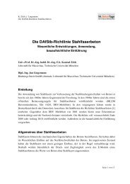
ABSTRACT<br />
With unbonded post-tensioning it is possible to design various structures or to<br />
strengthen them. In Germany, not before the 90ies of the last century this type<br />
of post-tensioning was able to succeed against the “Freyssinet”-method of<br />
bonded post-tensioning - about 60 years after the first post-tensioned bridge<br />
worldwide was built in Aue/Saxony. This bridge also was post-tensioned with<br />
unbonded <strong>and</strong> restressable bars. This paper focuses on the main features, the<br />
pros <strong>and</strong> cons of unbonded post-tensioning for design, construction,<br />
maintenance <strong>and</strong> safety <strong>and</strong> finally presents some applications in Germany.<br />
Keywords: Post-Tensioning, unbonded, tendons, projects.<br />
1
<strong>Weiher</strong> <strong>and</strong> <strong>Zilch</strong> 2008 CBC<br />
INTRODUCTION<br />
Post-tensioned concrete structures combine the pros of steel <strong>and</strong> concrete. So, these<br />
structures or members are stiffer <strong>and</strong> show less cracking than comparable RC members. As a<br />
consequence, they can be designed more slender. Post-tensioning allowed in the past<br />
bridging of very big spans with concrete structures. After WWII, post-tensioning was applied<br />
to the majority of road <strong>and</strong> railway bridges 1,2,3 . Although the first pt bridge had unbonded<br />
tendons, the huge stock of concrete brides was built using bonded post-tensioning according<br />
to the ideas of Eugène Freyssinet. This did not change before the 90ies of last century, when<br />
first pilot project have been realized using external cables. Another reason for that<br />
development might have been the prohibition of building concrete bridges using segments in<br />
Germany.<br />
The first experiences in applying only external post-tensioning for road <strong>and</strong> railway bridges<br />
have been published in a workshop at University of Karlsruhe in 1998 4,5,6,7,8,9 . Since 1999<br />
post-tensioned concrete bridges with box-section must be built using external tendons (ARS<br />
17/1999 10,6 ). They have to be arranged outside the concrete cross section <strong>and</strong> inside the box.<br />
Moreover, the arrangement of tendons in the webs was forbidden for boxes because the<br />
compact arrangement of tendons often lead to consolidation problems <strong>and</strong> poor corrosion<br />
protection quality 11 . Using only external tendons with a restricted maximum force causes a<br />
high number of tendons in the box. In addition to design problems when arranging concrete<br />
deviators the concrete surfaces are difficult to reach for regular inspection (e.g. viaduct<br />
Rumbeck, figure 1). That’s why combined post-tensioning was invented. Some tendons (e.g.<br />
the primary tendons) are arranged internally with bond. During the last years some pilot<br />
projects were realized using unbonded tendons instead of bond tendons as internal tendons.<br />
Unbonded tendons transfer normal forces only at the anchorages. This also applies to<br />
unbonded tendons that are arranged within the concrete cross section. By deflecting the tendons<br />
it is possible to compensate for external stresses due to bending („load balancing“).<br />
Anchor forces as well as deviation forces can be seen as loads to the structure.<br />
Fig. 1 Rumbeck Viaduct: External tendons during construction <strong>and</strong> at final state (courtesy of Schäfer)<br />
Fig. 2 RC T-Beam with external tendons 12<br />
2
<strong>Weiher</strong> <strong>and</strong> <strong>Zilch</strong> 2008 CBC<br />
TENDONS FOR UNBONDED POST-TENSIONING<br />
Following, presently used tendon systems for unbonded post-tension will be shown.<br />
Unbonded tendons systems consist of prestressing steel (wire, str<strong>and</strong>, compact str<strong>and</strong> or bar).<br />
The steel is protected from external influences by polyethylene sheathing (e.g. HDPE-pipe).<br />
For durable protection of the steel from corrosion the sheathings are filled with grout, grease<br />
or wax.<br />
EXTERNAL TENDONS<br />
External tendons can be distinguished by their cross section. Presently applied systems either<br />
are rectangular shaped or circular (Fig. 3). Deviation of tendons has to be done at the<br />
concrete deviator. To reduce its dimensions the radius of deviation has to be small which<br />
leads to high transverse loads. These loads might lead to significant imprints of the steel into<br />
the soft polyethylene, which has to be taken into account when designing for durability 13 .<br />
There are some opportunities to reduce the loading on the ducts, e.g. increasing the radius or<br />
using a different duct shape.<br />
For b<strong>and</strong> tendons the transverse loading can be determined exactly in contrast to bundle<br />
tendons. That’s why design of ducts can be done with a high reliability. Additionally, a lot of<br />
testing has be done in the past to investigate the imprint behaviour at concrete<br />
deviators 14,15,16 . To get an European technical approval ETA for an external tendon system it<br />
is necessary not only to show the suitability of steel <strong>and</strong> anchorage by load transfer, static<br />
<strong>and</strong> fatigue tests but also to show the suitability of the ducts with a test of a deviated tendon<br />
according to the European guideline ETAG 013, Ed. 2002 17 .<br />
a) b) c)<br />
Fig. 3 External tendon types, cross section at high points of the curvature 13<br />
INTERNAL TENDONS<br />
Internal unbonded tendons can be deflected continuously just like bonded tendons. In<br />
contrast to those the unbonded tendons can be restressed or even exchanged. The smallest<br />
tendon for unbonded pt is the monostr<strong>and</strong> (Fig. 4a). Arranging second polyethylene<br />
sheathing allows exchangeability of the monostr<strong>and</strong> (Fig. 4b). Monostr<strong>and</strong>s can be combined<br />
in different ways to form larger tendons. For example four monostr<strong>and</strong>s can be arranged in a<br />
line. Internal unbonded tendons are forming a void in the concrete section <strong>and</strong> thus may<br />
reduce the transverse force bearing capacity, especially in the bridge deck. The dimension of<br />
the created void shall be minimized <strong>and</strong> be very compact. A tendon design that accomplishes<br />
the requirement to the cross section very well is shown in Fig. 4c. Four rows of monostr<strong>and</strong>s<br />
(b<strong>and</strong>s) are stacked staggered to minimize the remaining spaces. The steel ratio of the tendon<br />
3
<strong>Weiher</strong> <strong>and</strong> <strong>Zilch</strong> 2008 CBC<br />
is at 45% for the not exchangeable type (Fig. 4c, Table 1). Presently used external tendons<br />
can also be arranged inside of the concrete section but they are clearly less compact. For pt of<br />
slabs the deviation radii usually are quite large <strong>and</strong> the tendons small – transverse loading of<br />
the steel to the ducts is of less importance. This is quite different when using loop-anchors<br />
with small radii of curvature. There you also have to proof the durability respectively the<br />
resistance of the duct against the loading by the steel members.<br />
a)<br />
b)<br />
c) d)<br />
Fig. 4 Internal tendon types, cross section at high points of the curvature 13<br />
Table 1 Filling ratio of steel for tendons with a prestressing force of about 3 MN<br />
___________________________________________________________________________<br />
Post-tensioning system (F ≈ 3 MN) Ap / Atotal<br />
SUSPA CD-66 (Fig. 3b) 27 %<br />
VBF-CMM D (Fig. 3a) 28 %<br />
VBF compact, one PE-duct (Fig. 4c) 45 %<br />
VBF compact, double PE-duct (Fig 4d) 29 %<br />
VT-CMM D (similar to Fig. 3a) 23 %<br />
VT-CMM KD (similar to Fig. 3a) 25 %<br />
Features of unbonded pt <strong>and</strong> consequences for design <strong>and</strong> construction<br />
Unbonded tendon systems basically differ from bonded systems by their corrosion protection<br />
of the steel. Unbonded tendons are only protected by the components of the tendon:<br />
corrosion protection mass, PE-HD sheathing(s). Bonded tendons using corrugated steel ducts<br />
need the surrounding concrete cover to protect the steel. Mainly, thin concrete cover (e.g. RC<br />
structures built before implementation of the national guideline ZTV-K 80 in 1980 19 ) caused<br />
corrosion of the prestressing steel in the past 1,11 .<br />
BOND / REINFORCEMENT<br />
Because the steel is not bonded to the concrete there is a higher need of reinforcing steel, as<br />
an increase of loading just leads to a small increase of steel stress – but over the total length<br />
of the tendon. In addition to that, the prestressing steel cannot be counted as steel that is<br />
necessary for limitation of crack width. Generally, more reinforcement makes the structure<br />
robust but also leads to higher costs.<br />
4
<strong>Weiher</strong> <strong>and</strong> <strong>Zilch</strong> 2008 CBC<br />
BOND / FATIGUE<br />
Unbonded tendons show very small stress ranges when the structure is loaded dynamically<br />
<strong>and</strong> due not tend to fatigue fracture (e.g. at coupling joints 1 ). The stress due to live loads<br />
dispenses all over the length of the tendons. At multi-span structures these stresses can even<br />
compensate each other. Concrete bridges with bonded pt that are subjected to fatigue danger<br />
can be strengthened very effectively 20 .<br />
FRICTION / FRETTING FATIGUE<br />
The immediate stress losses of a tendon depend on the elastic concrete contraction when<br />
stressing other tendons, on the slip of the wedges as well as on the friction when deviated.<br />
The friction coefficient of prefabricated tendons with waxlike corrosion protection mass <strong>and</strong><br />
polyethylene duct (e.g. monostr<strong>and</strong>) is significantly smaller than the one of bonded tendons<br />
with metal ducts. This is of special interest if large deflections have to be done, e.g. for tanks<br />
or multi-span bridges. There, a smaller amount of prestressing steel can be used for the same<br />
prestressing force necessary at certain points.<br />
Fretting occurs only at bond tendons between two metal friction partners. It depends on the<br />
pressure between those metal partners (e.g. str<strong>and</strong>-duct or str<strong>and</strong>-str<strong>and</strong>). For unbonded<br />
tendons fretting is not a problem because of the small stress ranges. That’s why the deviation<br />
radii can be chosen smaller with regard to this task 21 . However, it has to be taken into<br />
account that transverse pressure when deviating the tendon with a small radius might lead to<br />
deep imprints of the steel into the polyethylene <strong>and</strong> therefore might reduce the corrosion<br />
protection 13,23,24 .<br />
DESIGN AS RC MEMBER<br />
For concrete structures with only unbonded post-tensioning the concrete cover is not needed<br />
for the protection of the prestressing steel. The tendons are protected separately by wax <strong>and</strong><br />
PE-HD ducts. In contrast to bonded post-tensioning with metal ducts it is clearly less critical<br />
whether the structural concrete member is cracked which would allow the permeation of<br />
corrosion-promoting substances. Unbonded post-tensioned structural concrete members have<br />
to be designed only as RC members for serviceability limit state (SLS). A documented<br />
evidence of conformity has not to be accomplished. Larger maximum crack widths are<br />
allowed <strong>and</strong> decompression has not to be avoided. Thus, the required amount of reinforcing<br />
steel is smaller (see table 18 <strong>and</strong> 19 of DIN 1045-1 25 or Eurocode 2.<br />
RESTRESSABILITY, INSPECTION, EXCHANGABILITY<br />
One of the main aspects for the application of unbonded post-tensioning is its ability of<br />
restressing after completion of the structure. By using a hydraulic jack it is possible to<br />
restress the steel because there is no bond with the surrounding concrete. For example timedependant<br />
losses of the force like creep, shrinkage or relaxation of the steel can be<br />
compensated at a later time. When measuring the force of the jack with the oil pressure<br />
during lifting of the anchor it is also possible to check the prestressing force of the tendon.<br />
5
<strong>Weiher</strong> <strong>and</strong> <strong>Zilch</strong> 2008 CBC<br />
Here it is commendable to use jacks for monostr<strong>and</strong>s. At abutments enough space for<br />
h<strong>and</strong>ling has to be kept free or the backfill has to be removed. Both are very complex <strong>and</strong> its<br />
application mainly for short-span pt bridges is not economical. At multispan bridges most<br />
tendons are anchored at the diaphragms <strong>and</strong> thus are easy to access.<br />
If restressing is done, one has to bear in mind that the additional stressing length is large<br />
enough so that the “new” imprints of the wedges into the steel are not at the same place than<br />
the “old” imprints. Therefore, depending on the stress increase, a certain minimum length of<br />
the tendon is required - otherwise the tendon has to be exchanged. An exchange also is<br />
required if the tendon is damaged (e.g. by fire or v<strong>and</strong>alism).<br />
PRODUCT QUALITY<br />
Unbonded tendons are often fabricated completely in a factory. Therefore, grouting on site<br />
can be avoided. The quality of works <strong>and</strong> the schedule is not influenced by weather<br />
conditions (e.g. frost). With unbonded tendons the installation <strong>and</strong> stressing of the tendons<br />
can be performed almost entirely independent from the reinforcing <strong>and</strong> pouring of the<br />
concrete. When using internal tendons the quick assembly can be assured by preparing few<br />
supports. Between these supports the tendon finds its final vertical position due to its<br />
stiffness (“free tendon curvature” 29 ).<br />
In Germany, the arrangement of tendons in the webs of boxes has been forbidden in 1999.<br />
For T-beams this is not valid. Compact shaped cross sections are advantageous because they<br />
weaken the cross section of the RC less. The fabrication of unbonded tendons off-site not<br />
only guarantees a high quality of the products but moreover accelerates the construction<br />
progress. The tendons can be shipped to the site briefly before it will be installed. With mass<br />
products (e.g. automobile industry) this Just-in-Sequence-concept (JIS) led to remarkable<br />
time <strong>and</strong> cost savings 30 . To prevent damages of the soft PE-ducts there are higher dem<strong>and</strong>s<br />
on the accuracy of installation <strong>and</strong> h<strong>and</strong>ling on-site. Deviation along sharp edges must be<br />
avoided which might lead to cutting of the steel through the polyethylene.<br />
INDICATION OF FAILURE<br />
Simple indication of tendon failures can be achieved by using unbonded tendons. They<br />
consist of prestressing steel, a wax-like corrosion protection mass <strong>and</strong> polyethylene<br />
sheathing. Fig. 5 (left) shows a two span girder with a bonded tendon (top) <strong>and</strong> a girder with<br />
an unbonded tendon (bottom), both with failed tendons close to the left support, e.g. due to<br />
stress corrosion. For the girder with the unbonded tendon, a local tendon failure is equivalent<br />
to a total failure along the total tendon length since there is no reintroduction of the force due<br />
to bonding. Therefore, the prestressing is also reduced in the areas of maximum bending<br />
moments (mid-support, mid-span) so that the girder will crack in these areas. Concrete<br />
cracking can be observed by many monitoring systems <strong>and</strong> can be verified numerically as an<br />
indication of tendon failure. The cracks are indicating the failure of the tendon; see Fig. 5<br />
(left). <strong>Zilch</strong>, Hennecke <strong>and</strong> Gläser have shown in their research, that cracking occurs far from<br />
the ultimate limit state of the structure 26 . In Fig. 5 (right) they illustrate their results in which<br />
a rather long part of a span will show cracks at rates of prestressing losses that do not harm<br />
6
<strong>Weiher</strong> <strong>and</strong> <strong>Zilch</strong> 2008 CBC<br />
the load capacity (e.g. 25% loss). Hence, a sudden collapse of the structure (e.g. a bridge) can<br />
be avoided by using unbonded tendons.<br />
x<br />
L L<br />
7<br />
100%<br />
Fig. 5 Early indication of failure for unbonded post-tensioning<br />
EXAMPLES / PILOT PROJECTS<br />
length of cracked zone / span (x/L)<br />
80%<br />
60%<br />
40%<br />
20%<br />
fctk,0.05<br />
fctm<br />
permanent<br />
0%<br />
0,0% 12,5% 25,0% 37,5% 50,0%<br />
loss of prestressing<br />
Already since the 90ies of the last century external tendons have been widespread in<br />
Germany. For road bridges with box girders the combination with internal bonded tendons<br />
(only in deck <strong>and</strong> bottom slab) has shown to be better. The pros of unbonded post-tensioning<br />
(product quality, structural safety, restressability <strong>and</strong> exchangability etc.) can be combined<br />
with the pros of bonded post-tensioning (larger lever arm, bigger steel strength for ULS,<br />
continuous tendon curvature). However, the structure cannot be seen as an RC member any<br />
more because of the bonded tendons <strong>and</strong> thus has to fulfil more strict design criteria in SLS.<br />
Since few years unbonded tendons have been uses as internal tendons. Pilot projectrs have<br />
been realized, like Mühlenberg Viaduct (North Rhine-Westphalia) or Roßriether Graben<br />
(Bavaria). For tank construction the advantages of internal guided unbonded post-tensioning<br />
can be extensively used, e.g. for the four digestion tanks of the sewage water treatment plant<br />
“Gut Großlappen” near Munich, Germany. One example of the vast application opportunities<br />
of unbonded post-tensioning is demonstrated at a pedestrian bridge with a granite slab.<br />
MÜHLENBERG VIADUCT<br />
The Mühlenberg Viaduct at Arnsberg (B 229n) spans with six fields a distance of 255m 31 .<br />
The box is 2,45m in height (see Fig. 6a). The structure was built stepwise. According to<br />
Eisler 31 twelve external tendons à 3 MN <strong>and</strong> two precaution tendons would have been<br />
necessary if not using internal tendons. This would have led to problems of space <strong>and</strong><br />
uneconomic diaphragms. For internal tendons unbonded ones have been chosen. Fig. 6b<br />
shows the pt concept. The internal tendons are arranged as additional tendons spanwise in the<br />
bottom slab for the pier regions <strong>and</strong> in the deck slab for mid-span. The external tendons are<br />
deviated at all diaphragms (pier, approaching span <strong>and</strong> twice in the inner spans). These<br />
diaphragms or concrete deviator are densely reinforced concrete members serve both for<br />
deviation <strong>and</strong> for anchoring (see Fig. 6c). Despite the higher prices for unbonded tendons in
<strong>Weiher</strong> <strong>and</strong> <strong>Zilch</strong> 2008 CBC<br />
comparison to bonded tendons <strong>and</strong> a higher dem<strong>and</strong> of reinforcing steel the savings of prestressing<br />
in this project did not lead to higher costs 31 . With this concept it is possible to<br />
realise the pros pointed out before, without higher efforts. A durable <strong>and</strong> safe product can be<br />
offered the owner. One has to bear in mind that the unbonded pt systems for internal use<br />
differ in quality <strong>and</strong> suitability.<br />
a)<br />
c)<br />
Fig. 6 a: cross section, arrangement of internal <strong>and</strong> external tendons at diaphragm<br />
Fig. 6 b: longitudinal section, pt span 1 to 3<br />
Fig. 6 b: detail of diaphragm, deviation <strong>and</strong> anchoring of external (red) <strong>and</strong> internal (blue) tendons<br />
ROSSRIETHER GRABEN<br />
Near Mellrichstadt (Bavaria) another pilot project with combined unbonded pt with external<br />
<strong>and</strong> internal tendons has been realized (three span structure with single box - approaches 40m<br />
each, inner span 50 m). As internal tendons a bundle tendon with wires in a duct has been<br />
used 32,33 . They are arranged in the slabs like at the Mühlenberg Viaduct. In each span just one<br />
concrete deviator has been placed. Also for this project there was no difference in the initial<br />
costs compared to the use of bonded internal tendons 32 . The design has been done as to the<br />
national code DIN 1045-1 25 <strong>and</strong> DIN Fachbericht 102 34 which are based on the Eurocodes 1<br />
<strong>and</strong> 2. Within this project the exchange of the steel of an internal tendon has been shown to<br />
check the feasibility 33 . The PE duct remained inside the structure. Transverse pressure<br />
created friction <strong>and</strong> clamping between the wires also led to a high force necessary for<br />
removal. Thus, the length <strong>and</strong> the deflections will be limited if the duct shall not be stressed<br />
to seriously. After re-installation of the prestressing steel, the duct has been refilled with wax.<br />
8<br />
b)
<strong>Weiher</strong> <strong>and</strong> <strong>Zilch</strong> 2008 CBC<br />
Fig. 7 Roßriether Graben<br />
GUT GROSSLAPPEN<br />
North of Munich the construction of four digestion tanks has been finished in 2007. The<br />
complex post-tensioning of the digestion tanks has been realized by internal monostr<strong>and</strong><br />
b<strong>and</strong>s (four monostr<strong>and</strong>s in a row):<br />
- Ring post-tensioning: horizontal tendons are distributed over the height of the tanks<br />
<strong>and</strong> string around the tanks.<br />
- Meridian post-tensioning (Fig. 8a, Fig. 8c): Vertical tendons are arranged all around<br />
the tanks, they are anchored with loops in the bottom of the tanks.<br />
- Conic post-tensioning (Fig. 8b): The bottom cone is hung up, the support is realized<br />
at a ring founded on bore piles which is over the bottom cone.<br />
a)<br />
b)<br />
Fig. 8 digestion tanks a: meridian pt, b: conic pt, c: top view during construction<br />
9<br />
c)
<strong>Weiher</strong> <strong>and</strong> <strong>Zilch</strong> 2008 CBC<br />
The use of numerous small unbonded tendons was in a specific proposal preferred to less big<br />
tendons with bonded post-tensioning. Thereby decompression would have occurred – when<br />
using unbonded tendons there are fewer requirements to fulfil <strong>and</strong> consequently there is the<br />
potential to save a lot of prestressing 39 . On the other h<strong>and</strong> there is a high effort for planning,<br />
design <strong>and</strong> ensuring the accurate installation of the post-tensioning. The use of small tendon<br />
units for the tank construction also has to be assessed positively because of easier installation<br />
between the rebars <strong>and</strong> easier pouring of the self-consolidating concrete.<br />
POST-TENSIONED GRANITE<br />
Unbonded tendons are suitable for external application because of their corrosion protection<br />
system. A pedestrian bridge out of granite delivered by the company Kusser, Aicha v. Wald,<br />
has been prestressed by Monostr<strong>and</strong>s without any additional reinforcement (see Fig. 9). To<br />
proof the suitability of granite load transfer to the structure testing has been done according<br />
to the ETAG 013 at Technische Universität München.<br />
a)<br />
b)<br />
c)<br />
Fig. 9 Single span granite bridge post-tensioned with monostr<strong>and</strong>s<br />
REFERENCES<br />
1. Maurer, R., <strong>Zilch</strong>, K., Bäätjer, G., <strong>and</strong> <strong>Weiher</strong>, H., “Sicherheit von Spannbetonbrücken“,<br />
Research Report, 2006.<br />
2. Benning, H.-H., “Spannbetonbrücken der Bundesfernstraßen – Grundsätze zu Bau und<br />
Erhaltung“, Proceedings of Münchner <strong>Massivbau</strong>-Seminar, 2006.<br />
10<br />
d)<br />
e)
<strong>Weiher</strong> <strong>and</strong> <strong>Zilch</strong> 2008 CBC<br />
3. Muncke, M., “Ingenieurbauwerke bei der Deutschen Bahn AG: Anforderungen und<br />
Gestaltung“, [Umrisse] Zeitschrift <strong>für</strong> Baukultur, Vol. 2, 4, 2004, pp. 8-12.<br />
4. Thal, H., “Verbundlose Vorspannung mit B<strong>and</strong>spanngliedern“, Externe Vorspannung und<br />
Segmentbauweise, edited by Josef Eibl, Berlin: Ernst & Sohn, 1998.<br />
5. Eibl, J., “Die externe Vorspannung in Deutschl<strong>and</strong> – Entwicklung und Ausblick“.<br />
Externe Vorspannung und Segmentbauweise, edited by Josef Eibl, Berlin: Ernst & Sohn,<br />
1998.<br />
6. St<strong>and</strong>fuß, F. “Die externe und verbundlose Vorspannung von Straßenbrücken aus Beton<br />
aus der Sicht des Bauherrn“, Externe Vorspannung und Segmentbauweise, edited by<br />
Josef Eibl, Berlin: Ernst & Sohn, 1998.<br />
7. Großmann, F., “Wirtschaftlichkeit von extern vorgespannten Brücken“, Externe<br />
Vorspannung und Segmentbauweise, edited by Josef Eibl, Berlin: Ernst & Sohn, 1998.<br />
8. Iványi, G., <strong>and</strong> Buschmeyer, W., “Brückenüberbauten mit interner Vorspannung ohne<br />
Verbund“, Externe Vorspannung und Segmentbauweise, edited by Josef Eibl, Berlin:<br />
Ernst & Sohn, 1998.<br />
9. Pellar, A., <strong>and</strong> Retzepis, I., “Erfahrungen mit dem ersten extern vorgespannten<br />
Eisenbahn-Brückenbauwerk <strong>für</strong> die Deutsche Bahn AG“, Externe Vorspannung und<br />
Segmentbauweise, edited by Josef Eibl, Berlin: Ernst & Sohn, 1998.<br />
10. German Ministry of Infrastructure: “ARS 17/1999 Spannbetonbrücken – Richtlinie <strong>für</strong><br />
Betonbrücken mit externen Spanngliedern“, Dortmund: Verkehrsblattverlag, 1999.<br />
11. <strong>Zilch</strong>, K., <strong>and</strong> <strong>Weiher</strong>, H., “Sicherheit von Spannbetonbrücken - Zust<strong>and</strong> von<br />
Großbrücken im Zuge von Bundesfernstraßen“, Bauingenieur, Vol. 82, 1, 2007, pp. 14-<br />
24, Berlin: Springer VDI Verlag.<br />
12. <strong>Zilch</strong>, K., <strong>and</strong> Zehetmaier, G., “Bemessung im konstruktiven Betonbau, nach DIN 1045-1<br />
und DIN EN-1992-1-1“, Berlin: Springer Verlag, 2005.<br />
13. <strong>Weiher</strong>, H., “Verhalten von PE-HD Schutzhüllen bei der Umlenkung von verbundlosen<br />
Spanngliedern“, PhD-Thesis, TU München, 2007.<br />
14. <strong>Zilch</strong>, K., <strong>and</strong> <strong>Weiher</strong>, H., “Auswirkungen von zweiaxialer Umlenkung auf die<br />
Ergebnisse des Umlenkversuchs bei externen Spanngliedern“, Stuttgart: Fraunhofer IRB<br />
Verlag, 2006.<br />
15. Hegger, J., Cordes, H., <strong>and</strong> Neuser, J. U., “Dauerhaftigkeit von Polyethylen-Schutzhüllen<br />
externer Spannglieder an Umlenkstellen“, Report. Stuttgart: Fraunhofer IRB Verlag,<br />
2002.<br />
16. Hegger, J., Peters, S., <strong>and</strong> Schmitz, M., “Dauerhaftigkeit von Polyethylen-Schutzhüllen<br />
externer Spannglieder an Umlenkstellen bei wechselnden Beanspruchungszuständen“,<br />
Stuttgart: Fraunhofer IRB Verlag, 2005.<br />
17. ETAG 013, Edition June 2002. ”Guideline for European Technical Approval of Post-<br />
Tensioning Kits for Prestressing of Structures”, EOTA, Brussels, 2002.<br />
18. http://www.dwk-koeln.de, seen on 2nd of February 2007.<br />
19. ZTV-K 80. “Zusätzliche Technische Vertragsbedingungen <strong>für</strong> Kunstbauten“, Edition<br />
1980.<br />
20. Zichner, T., “Inst<strong>and</strong>setzung von Koppelfugen von Spannbetonbrücken“, Dehn,<br />
Holschemacher, Tue (Editors): Sanierung und Verstärkung von <strong>Massivbau</strong>ten,<br />
Innovationen im Bauwesen, Beiträge aus Praxis und Wissenschaft. Berlin: Bauwerk<br />
Verlag, 2007.<br />
11
<strong>Weiher</strong> <strong>and</strong> <strong>Zilch</strong> 2008 CBC<br />
21. Hegger, J., <strong>and</strong> Abel, M., “Kunststoffhüllrohre <strong>für</strong> Spannglieder mit nachträglichem<br />
Verbund - Versuche und Bemessungsempfehlungen“, Beton- und Stahlbetonbau, Vol. 94,<br />
1, 1999, 6-13, Berlin: Ernst & Sohn.<br />
22. <strong>Zilch</strong>, K., Diederichs, C. J., <strong>and</strong> Katzenbach, R. (Editors): “H<strong>and</strong>buch <strong>für</strong> Bauingenieure:<br />
Technik, Organisation und Wirtschaftlichkeit – Fachwissen in einer H<strong>and</strong>“, Berlin,<br />
Heidelberg: Springer Verlag, 2001.<br />
23. Rostásy, F. S., <strong>and</strong> Holzenkämpfer, P., “Auswirkungen der zulässigen<br />
Spannstahlspannungen von EC 2, Teil 1 auf die Zulassung von Spannverfahren“,<br />
Research Report, TU Braunschweig, IBMB, 1994.<br />
24. Rombach, G., “Spannbetonbau“, Berlin: Ernst & Sohn, 2003.<br />
25. DIN 1045-1: “Tragwerke aus Beton, Stahlbeton und Spann-beton, Teil 1: Bemessung und<br />
Konstruktion“, Vol. 07.2001.<br />
26. <strong>Zilch</strong>, K., Hennecke, M., <strong>and</strong> Gläser, C., “St<strong>and</strong> der Entwicklung interner verbundloser<br />
Vorspannung – System und Anwendungen“. F. Dehn, K. Holschemacher und N. V. Tue<br />
(Editors): Neue Entwicklungen im Brückenbau – Innovationen im Bauwesen – Beiträge<br />
aus Praxis und Wissenschaft, Berlin: Bauwerk Verlag, 2004.<br />
27. Holst, K. H., <strong>and</strong> Holst, R., “Brücken aus Stahlbeton und Spannbeton, Entwurf,<br />
Konstruktion und Berechnung“, Volume 5. Berlin: Ernst & Sohn, 2004.<br />
28. Rossner, W., <strong>and</strong> Graubner, C.-A., “Spannbetonbauwerke, Teil 3: Bemessungsbeispiele<br />
nach DIN 1045-1 und DIN-Fachbericht 102“, Berlin: Ernst & Sohn, 2003.<br />
29. Wicke, M., <strong>and</strong> Maier, K., “Die Freie Spanngliedlage“, Bauingenieur, Vol. 73, 4, 1998,<br />
162-169, Berlin: Springer VDI Verlag.<br />
30. Kok, A. G., <strong>and</strong> Graves, S. C. (Editors), “Supply Chain Management: Design,<br />
Coordination <strong>and</strong> Operation, Volume 11”, Amsterdam: Elsevier, 2003.<br />
31. Eisler, R., “Neue Mischbauweise mit interner Vorspannung ohne Verbund – Pilotprojekt<br />
Mühlenbergbrücke“, Proceedings of 10. Münchener <strong>Massivbau</strong> Seminar, München,<br />
2006.<br />
32. Haupt, R., <strong>and</strong> Hennecke, M., “Pilotprojekt Roßriether-Graben-Brücke – Mischbauweise<br />
mit verbundloser Vorspannung“, Proceedings of 10. Münchener <strong>Massivbau</strong> Seminar,<br />
München, 2006.<br />
33. Fuchs, M., Friedrich, J., <strong>and</strong> Haupt, R., “Pilotprojekt Roßriether - Grabenbrücke,<br />
Spannbetonhohlkasten in Mischbauweise mit internen Spanngliedern ohne Verbund“,<br />
Presentation at the Münchner <strong>Massivbau</strong>kolloquium, 15.01.2007.<br />
34. DIN Fachbericht 102: “Betonbrücken“, Berlin u.a.: Beuth-Verlag, 2003.<br />
35. Bergmeister, K., <strong>and</strong> Wörner, J.-D. (Editors), “Beton-Kalender 2004: Brücken und<br />
Parkhäuser“, Berlin: Ernst & Sohn, 2004.<br />
36. <strong>Zilch</strong>, K., Penka, E., <strong>and</strong> Gläser, C., “Ankündigungsverhalten von Massivbrücken mit<br />
verbundlosen Spanngliedern – Messgrößen und Konzepte“, Proceedings of 29.<br />
Darmstädter <strong>Massivbau</strong>seminar „Sicherheitsgewinn durch Monitoring?“, 2006.<br />
37. Stettner, C., “Aspects on structural design <strong>and</strong> building process”, Unpublished Report of<br />
<strong>Zilch</strong>+Müller Ingenieure GmbH, 2006.<br />
38. http://www.arge-ggl.de, seen on 20th of February 2007.<br />
39. Jäger, P., “Erfahrung mit der Anwendung der DIN 1045-1 am Beispiel Klärwerk Gut<br />
Großlappen, SEW, Teil 2: Das Vorspannkonzept der Ausführungsplanung“, <strong>Zilch</strong> (Editor):<br />
<strong>Massivbau</strong> 2004 – Forschung, Entwicklungen und Anwendungen, Düsseldorf:<br />
Springer-VDI-Verlag, 2004.<br />
12