Ursalink UR51 Industrial Cellular Router User Guide

You also want an ePaper? Increase the reach of your titles
YUMPU automatically turns print PDFs into web optimized ePapers that Google loves.
<strong>UR51</strong> <strong>User</strong> <strong>Guide</strong><br />
1
<strong>UR51</strong> <strong>User</strong> <strong>Guide</strong><br />
Preface<br />
Thanks for choosing <strong>Ursalink</strong> <strong>UR51</strong> industrial cellular router. The <strong>UR51</strong> industrial cellular<br />
router delivers tenacious connection over network with full-featured design such as<br />
automated failover/failback, extended operating temperature, dual SIM cards, hardware<br />
watchdog, VPN, Gigabit Ethernet and beyond.<br />
This guide describes how to configure and operate the <strong>UR51</strong> industrial cellular router. You<br />
can refer to it for detailed functionality and router configuration.<br />
Readers<br />
This guide is mainly intended for the following users:<br />
- Network Planners<br />
- On-site technical support and maintenance personnel<br />
- Network administrators responsible for network configuration and maintenance<br />
© 2017 Xiamen <strong>Ursalink</strong> Technology Co., Ltd.<br />
All rights reserved.<br />
All information in this user guide is protected by copyright law. Whereby, no organization or<br />
individual shall copy or reproduce the whole or part of this user guide by any means without<br />
written authorization from Xiamen <strong>Ursalink</strong> Technology Co., Ltd.<br />
Products Covered<br />
This guide explains how to configure the following devices:<br />
• <strong>Ursalink</strong> <strong>UR51</strong> <strong>Industrial</strong> <strong>Cellular</strong> <strong>Router</strong><br />
Related Documents<br />
Document<br />
<strong>Ursalink</strong> <strong>UR51</strong> Datasheet<br />
<strong>Ursalink</strong> <strong>UR51</strong> Quick Start <strong>Guide</strong><br />
Description<br />
Datasheet for the <strong>Ursalink</strong> <strong>UR51</strong> industrial<br />
cellular router.<br />
Quick installation guide for the <strong>Ursalink</strong> <strong>UR51</strong><br />
industrial cellular router.<br />
2
<strong>UR51</strong> <strong>User</strong> <strong>Guide</strong><br />
Declaration of Conformity<br />
<strong>UR51</strong> is in conformity with the essential requirements and other relevant provisions of the<br />
CE, FCC, and RoHS.<br />
For assistance, please contact<br />
<strong>Ursalink</strong> technical support:<br />
Email: support@ursalink.com<br />
Tel.: 86-592-5023060<br />
Fax: 86-592-5023065<br />
Revision History<br />
Date Doc Version Description<br />
Dec. 22, 2017 V.1.0.0 Initial version<br />
3
<strong>UR51</strong> <strong>User</strong> <strong>Guide</strong><br />
Contents<br />
Chapter 1 Product Introduction.......................................................................................................... 7<br />
1.1 Overview................................................................................................................................7<br />
1.2 Advantages............................................................................................................................ 8<br />
1.3 Specifications.......................................................................................................................10<br />
1.4 Dimensions (mm)................................................................................................................ 11<br />
Chapter 2 Installation........................................................................................................................ 12<br />
2.1 General Packing List............................................................................................................ 12<br />
2.2 Product Overview................................................................................................................13<br />
2.3 LED Indicators......................................................................................................................13<br />
2.4 Ethernet Port Indicators......................................................................................................14<br />
2.5 PIN Definition...................................................................................................................... 14<br />
2.6 Reset Button........................................................................................................................15<br />
2.7 SIM Card Installation........................................................................................................... 15<br />
2.8 Micro SD card Installation................................................................................................... 16<br />
2.9 <strong>Cellular</strong> Antenna Installation...............................................................................................16<br />
2.10 Mounting the <strong>Router</strong>.........................................................................................................16<br />
2.11 Connect the <strong>Router</strong> to a Computer.................................................................................. 17<br />
2.12 Installation of Power Supply and Protective Grounding.................................................. 17<br />
2.12.1 Power Supply Installation...................................................................................... 17<br />
2.12.2 Protective Grounding Installation..........................................................................18<br />
Chapter 3 Access to Web GUI........................................................................................................... 19<br />
3.1 PC Configuration for Web GUI Access to <strong>Router</strong>................................................................ 19<br />
3.2 Access to Web GUI of <strong>Router</strong>..............................................................................................20<br />
Chapter 4 Web Configuration........................................................................................................... 22<br />
4.1 Status...................................................................................................................................22<br />
4.1.1 Overview.................................................................................................................. 22<br />
4.1.2 <strong>Cellular</strong>......................................................................................................................23<br />
4.1.3 Network....................................................................................................................24<br />
4.1.4 VPN...........................................................................................................................25<br />
4.1.5 Routing Information.................................................................................................26<br />
4.1.6 Host List....................................................................................................................27<br />
4.2 Network...............................................................................................................................27<br />
4.2.1 Interface................................................................................................................... 27<br />
4.2.1.1 Port................................................................................................................27<br />
4.2.1.2 LAN................................................................................................................ 28<br />
4.2.1.3 VLAN Trunk....................................................................................................28<br />
4.2.1.4 <strong>Cellular</strong>.......................................................................................................... 29<br />
4.2.1.5 Loopback....................................................................................................... 32<br />
4.2.2 Firewall..................................................................................................................... 33<br />
4.2.2.1 ACL.................................................................................................................33<br />
4.2.2.2 DMZ...............................................................................................................34<br />
4.2.2.3 Port Mapping................................................................................................ 35<br />
4
<strong>UR51</strong> <strong>User</strong> <strong>Guide</strong><br />
4.2.2.4 MAC Binding..................................................................................................36<br />
4.2.3 QoS........................................................................................................................... 36<br />
4.2.3.1 QoS (Download/Upload)...............................................................................36<br />
4.2.4 DHCP.........................................................................................................................37<br />
4.2.4.1 DHCP Server.................................................................................................. 37<br />
4.2.4.2 DHCP Relay....................................................................................................39<br />
4.2.5 DDNS........................................................................................................................ 39<br />
4.2.6 Link Failover..............................................................................................................40<br />
4.2.6.1 SLA.................................................................................................................41<br />
4.2.6.2 Track.............................................................................................................. 41<br />
4.2.6.3 VRRP..............................................................................................................43<br />
4.2.7 Routing..................................................................................................................... 45<br />
4.2.7.1 Static Routing................................................................................................ 45<br />
4.2.7.2 RIP................................................................................................................. 45<br />
4.2.7.3 OSPF.............................................................................................................. 49<br />
4.2.7.4 Routing Filtering............................................................................................53<br />
4.2.8 VPN...........................................................................................................................54<br />
4.2.8.1 DMVPN..........................................................................................................55<br />
4.2.8.2 IPSec.............................................................................................................. 56<br />
4.2.8.3 GRE................................................................................................................ 59<br />
4.2.8.4 L2TP...............................................................................................................60<br />
4.2.8.5 PPTP...............................................................................................................62<br />
4.2.8.6 OpenVPN Client............................................................................................ 64<br />
4.2.8.7 OpenVPN Server........................................................................................... 65<br />
4.2.8.8 Certifications................................................................................................. 67<br />
4.3 System................................................................................................................................. 69<br />
4.3.1 General Settings....................................................................................................... 69<br />
4.3.1.1 General..........................................................................................................69<br />
4.3.1.3 System Time.................................................................................................. 70<br />
4.3.1.4 SMTP............................................................................................................. 72<br />
4.3.1.5 Phone............................................................................................................ 73<br />
4.3.1.6 Storage.......................................................................................................... 74<br />
4.3.2 <strong>User</strong> Management................................................................................................... 74<br />
4.3.2.1 Account......................................................................................................... 74<br />
4.3.2.2 <strong>User</strong> management.........................................................................................75<br />
4.3.3 SNMP........................................................................................................................75<br />
4.3.3.1 SNMP.............................................................................................................76<br />
4.3.3.2 MIB View....................................................................................................... 77<br />
4.3.3.3 VACM.............................................................................................................77<br />
4.3.3.4 Trap................................................................................................................78<br />
4.3.3.5 MIB................................................................................................................ 79<br />
4.3.4 AAA...................................................................................................................................79<br />
4.3.4.1 Radius............................................................................................................79<br />
4.3.4.2 Tacacs+.......................................................................................................... 80<br />
5
<strong>UR51</strong> <strong>User</strong> <strong>Guide</strong><br />
4.3.4.3 LDAP.............................................................................................................. 80<br />
4.3.4.4 Authentication.............................................................................................. 81<br />
4.3.5 Device Management................................................................................................ 82<br />
4.3.6 Events....................................................................................................................... 83<br />
4.3.6.1 Events............................................................................................................ 83<br />
4.3.6.2 Events Settings.............................................................................................. 84<br />
4.4 <strong>Industrial</strong> Interface.............................................................................................................. 85<br />
4.4.1 Serial Port................................................................................................................. 85<br />
4.4.2 Modbus Master........................................................................................................89<br />
4.4.2.1 Modbus Master.............................................................................................89<br />
4.4.2.2 Channel......................................................................................................... 89<br />
4.5 Maintenance....................................................................................................................... 91<br />
4.5.1 Tools..........................................................................................................................91<br />
4.5.1.1 Ping................................................................................................................91<br />
4.5.1.2 Traceroute..................................................................................................... 92<br />
4.5.2 Schedule................................................................................................................... 92<br />
4.5.3 Log............................................................................................................................ 93<br />
4.5.3.1 System Log.................................................................................................... 93<br />
4.5.3.2 Log Settings................................................................................................... 94<br />
4.5.4 Upgrade....................................................................................................................94<br />
4.5.5 Backup and Restore..................................................................................................95<br />
4.5.6 Reboot...................................................................................................................... 96<br />
Chapter 5 Application Examples....................................................................................................... 98<br />
5.1 Account Info Management................................................................................................. 98<br />
5.2 Common <strong>User</strong> Management...............................................................................................98<br />
5.3 System Time Management................................................................................................. 99<br />
5.4 Backup and Restore Configuration................................................................................... 100<br />
5.5 Restore Factory Defaults................................................................................................... 102<br />
5.5.1 Via Web Interface...................................................................................................102<br />
5.5.2 Via Hardware..........................................................................................................103<br />
5.6 Firmware Upgrade.............................................................................................................104<br />
5.7 Events Application Example.............................................................................................. 106<br />
5.8 Schedule Application Example..........................................................................................108<br />
5.9 Logs and Diagnostics......................................................................................................... 109<br />
5.10 SNMP Application Example.............................................................................................110<br />
5.11 <strong>Cellular</strong> Connection.........................................................................................................113<br />
5.12 Dual SIM Backup Application Example........................................................................... 115<br />
5.13 VRRP Application Example..............................................................................................118<br />
5.14 NAT Application Example................................................................................................ 121<br />
5.15 Access Control Application Example...............................................................................121<br />
5.16 QoS Application Example................................................................................................ 122<br />
5.17 DTU Application Example................................................................................................124<br />
5.18 PPTP Application Example...............................................................................................127<br />
6
<strong>UR51</strong> <strong>User</strong> <strong>Guide</strong><br />
Chapter 1 Product Introduction<br />
1.1 Overview<br />
7
<strong>UR51</strong> <strong>User</strong> <strong>Guide</strong><br />
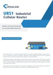
<strong>Ursalink</strong> <strong>UR51</strong> is an industrial cellular router with embedded intelligent software features<br />
that are designed for multifarious M2M/IoT applications. Supporting global WCDMA and 4G<br />
LTE, <strong>UR51</strong> provides drop-in connectivity for operators and makes a giant leap in maximizing<br />
uptime.<br />
Adopting high-performance and low-power consumption industrial platform of 64-bit CPU<br />
and wireless module, the <strong>UR51</strong> is capable of providing wire-speed network with a typical<br />
1.8W power consumption and ultra-small package to ensure the extremely safe and reliable<br />
connection to the wireless network.<br />
Meanwhile, the <strong>UR51</strong> also supports Gigabit Ethernet port, serial port (RS232/RS485), which<br />
enables you to scale up M2M application combining data and video in limited time and<br />
budget.<br />
The <strong>UR51</strong> is particularly ideal for smart grid, digital media installations, industrial automation,<br />
telemetry equipment, medical device, digital factory, finance, payment device, environment<br />
protection, water conservancy and so on.<br />
Figure 1-1<br />
1.2 Advantages<br />
Benefits<br />
- Built-in industrial strong CPU, big memory; Micro SD card is available to support further<br />
development and customized requirements<br />
- Fast Ethernet is applied to all models of <strong>Ursalink</strong> routers for lightning transmission of<br />
data<br />
- Dual SIM cards for backup between multiple carriers networking and global 2G/3G/LTE<br />
options make it easy to get connected<br />
- Flexible modular design provides users with different connection modules like Ethernet,<br />
serial port for connecting diverse field assets<br />
- Rugged enclosure, optimized for DIN rail or shelf mounting<br />
- 3-year warranty included<br />
8
<strong>UR51</strong> <strong>User</strong> <strong>Guide</strong><br />
Security & Reliability<br />
- Automated failover/failback between Ethernet and <strong>Cellular</strong> (dual SIM)<br />
- Enable unit with security frameworks like IPsec/OpenVPN/GRE/L2TP/PPTP/ DMVPN<br />
- Embed hardware watchdog, able to automatically recover from various failure, ensure<br />
highest level of availability<br />
- Establish a secured mechanism on centralized authentication and authorization of device<br />
access by supporting AAA (Tacacs+, Radius, LDAP, local authentication) and multiple<br />
levels of user authority<br />
-<br />
Easy Maintenance<br />
- <strong>Ursalink</strong> Device Management Platform provides easy setup, mass configuration, and<br />
centralized management of remote devices<br />
- The user-friendly web interface design and more than one option of upgrade help<br />
administrator to manage the device as easy as pie<br />
- WEB GUI and CLI enable the admin to achieve simple management and quick<br />
configuration among a large quantity of devices<br />
- Efficiently manage the remote routers on the existing platform through the industrial<br />
standard SNMP<br />
Capabilities<br />
- Link remote devices in an environment where communication technologies are<br />
constantly changing<br />
- <strong>Industrial</strong> ARM Cortex A7 processor, high-performance operating up to 528MHz with low<br />
power consumption below 1W, and 128 MB memory available to support more<br />
applications<br />
- Support rich protocols like SNMP, MQTT, Modbus bridging, RIP, OSPF<br />
- Support wide operating temperature ranging from -40°C to 70°C/-40°F to 158°F<br />
9
<strong>UR51</strong> <strong>User</strong> <strong>Guide</strong><br />
1.3 Specifications<br />
<strong>Cellular</strong> Interfaces<br />
Connectors<br />
2 × 50 Ω SMA (Center pin: female)<br />
SIM Slots 2<br />
Hardware System<br />
CPU<br />
Memory<br />
Storage<br />
580MHz, ARM Cortex A7<br />
128 MB Flash, 128 MB DDR3 RAM<br />
1 × Micro SD<br />
Ethernet<br />
Ports<br />
1 × RJ-45<br />
Physical Layer 10/100 Base-T (IEEE 802.3)<br />
Data Rate<br />
Interface<br />
Mode<br />
Serial Interface<br />
Ports<br />
Connector<br />
Baud Rate<br />
10/100 Mbps (auto-sensing)<br />
Auto MDI/MDIX<br />
Full or half duplex (auto-sensing)<br />
1 × RS232 or 1 × RS485<br />
DB9 Female<br />
300bps to 230400bps<br />
Software<br />
Network Protocols<br />
PPP, PPPOE, SNMP v1/v2c/v3, TCP, UDP, DHCP, RIPv1/v2,<br />
OSPF, DDNS, VRRP, HTTP, HTTPS, DNS, ARP, QOS, SNTP,<br />
Telnet, VLAN, SSH, etc.<br />
VPN Tunnel<br />
Access Authentication<br />
Firewall<br />
Management<br />
AAA<br />
Multilevel Authority<br />
Reliability<br />
Serial Port<br />
DMVPN/IPsec/OpenVPN/PPTP/L2TP/GRE<br />
CHAP/PAP/MS-CHAP/MS-CHAPV2<br />
ACL/DMZ/Port Mapping/MAC Binding<br />
Web, CLI, SMS, On-demand dial up<br />
Radius, Tacacs+, LDAP, Local Authentication<br />
Multiple levels of user authority<br />
VRRP, Dual SIM Backup<br />
Transparent (TCP Client/Server, UDP), Modbus Gateway<br />
Power Supply and Consumption<br />
(Modbus RTU to Modbus TCP)<br />
Connector<br />
Input Voltage<br />
2-pin with 5.08 mm terminal block<br />
9-48 VDC<br />
10
<strong>UR51</strong> <strong>User</strong> <strong>Guide</strong><br />
Power Consumption<br />
Physical Characteristics<br />
Ingress Protection<br />
Housing & Weight<br />
Dimensions<br />
Mounting<br />
Others<br />
Reset Button<br />
LED Indicators<br />
Built-in<br />
Certifications<br />
IP30<br />
Metal, 365 g (0.80 lb)<br />
100 x 96.1 x 30 mm (3.94 x 3.78 x 1.18 in)<br />
Desktop, wall or DIN rail mounting<br />
1 × RESET<br />
1 × POWER, 1 × STATUS, 1 × VPN,<br />
1 × SIM1, 1 × SIM2, 3 × Signal strength<br />
Watchdog, RTC, Timer<br />
RoHS, CE, FCC<br />
EMC IEC 61000-4-2 Level 3<br />
IEC 61000-4-3 Level 4<br />
IEC 61000-4-4 Level 3<br />
IEC 61000-4-5 Level 4<br />
IEC 61000-4-6 Level 3<br />
IEC 61000-4-8 Level 4<br />
Environmental<br />
Operating Temperature -40°C to +70°C (-40°F to +158°F) Reduced cellular<br />
Storage Temperature<br />
Ethernet Isolation<br />
Relative Humidity<br />
Typical 1.8 W, Max 2.7 W (In Non-PoE mode)<br />
performance above 60°C<br />
-40°C to +85°C (-40°F to +185°F)<br />
1.5 kV RMS<br />
0% to 95% (non-condensing) at 25°C/77°F<br />
1.4 Dimensions (mm)<br />
Figure 1-2<br />
11
<strong>UR51</strong> <strong>User</strong> <strong>Guide</strong><br />
Chapter 2 Installation<br />
2.1 General Packing List<br />
Before you begin to install the <strong>UR51</strong> router, please check the package contents to verify that<br />
you have received the items below.<br />
1 × <strong>UR51</strong> <strong>Router</strong> 1 × Ethernet Cable 1 × Power Adapter 2 × SIM Card Slots<br />
1 × 2-Pin Pluggable<br />
Terminal<br />
1 × Warranty Card 1 × Quick Start<br />
<strong>Guide</strong><br />
2 × Magnetic<br />
Mount <strong>Cellular</strong><br />
Antennas (Default)<br />
2 × Stubby <strong>Cellular</strong><br />
Antennas (Optional)<br />
1 × GPS Antenna<br />
(Optional)<br />
1 × Wall Mounting<br />
Bracket (Default)<br />
1 × DIN Rail Kit<br />
(Optional)<br />
1 × DB9 Male to Terminal<br />
Block Adapter (Optional)<br />
If any of the above items is missing or damaged, please contact your <strong>Ursalink</strong> sales<br />
representative.<br />
12
<strong>UR51</strong> <strong>User</strong> <strong>Guide</strong><br />
2.2 Product Overview<br />
A. Front Panel<br />
1 Main <strong>Cellular</strong> Antenna<br />
2 Micro SD Card Interface<br />
3 LED Indicator Area<br />
POWER: Power Indicator<br />
STATUS: Status Indicator<br />
: Signal Strength Indicator<br />
VPN: VPN Indicator<br />
SIM1: SIM1 Status Indicator<br />
SIM2: SIM2 Status Indicator<br />
4 SIM Card Slot 1 & SIM Card Slot 2<br />
5 AUX <strong>Cellular</strong> Antenna<br />
B. Rear Panel<br />
1 Grounding Stud<br />
2 Power Connector<br />
3 Ethernet Port Indicator<br />
4 Serial Port: RS232 or RS485<br />
5 Reset Button<br />
6 GPS Antenna Connector<br />
2.3 LED Indicators<br />
LED Indication Status Description<br />
POWER<br />
STATUS<br />
VPN<br />
SIM1/SIM2<br />
Power Status<br />
System Status<br />
VPN Status<br />
SIM Card Status<br />
On<br />
Off<br />
Green Light<br />
Off<br />
Green Light<br />
Off<br />
Off<br />
Green Light<br />
The power is switched on<br />
The power is switched off<br />
Static: Start-up<br />
Blinking slowly: the system is running<br />
properly<br />
The system goes wrong<br />
VPN is connected<br />
VPN is disconnected<br />
SIM1 or SIM2 is registering or fails to register<br />
(or there are no SIM cards inserted)<br />
Blinking slowly: SIM1 or SIM2 has been<br />
registered and is ready for dial-up<br />
13
<strong>UR51</strong> <strong>User</strong> <strong>Guide</strong><br />
Blinking rapidly: SIM1 or SIM2 has been<br />
registered and is dialing up now<br />
Static: SIM1 or SIM2 has been registered and<br />
dialed up successfully<br />
Off<br />
No signal<br />
Signal<br />
Strength<br />
Signal 1/2/3<br />
Green Light<br />
Static/Off/Off: weak signals with 1-10 ASU<br />
(please check if the antenna is installed<br />
correctly, or move the antenna to a suitable<br />
location to get better signal)<br />
Static/Static/Off: normal signals with 11-20<br />
ASU (average signal strength)<br />
Static/Static/Static: strong signals with 21-31<br />
ASU (signal is good)<br />
2.4 Ethernet Port Indicators<br />
Indicator Status Description<br />
On<br />
Connected<br />
Link Indicator (Orange) Blinking<br />
Transmitting data<br />
Off<br />
Disconnected<br />
2.5 PIN Definition<br />
PIN RS232 RS485 DI DO Description<br />
1 TXD --- --- --- Transmit Data<br />
2 RXD --- --- --- Receive Data<br />
3 --- A --- --- Data +<br />
4 --- B --- --- Data -<br />
5 GND --- GND --- Ground<br />
6 --- --- IN1 --- Digital Input1<br />
7 --- --- IN2 --- Digital Input2<br />
8 --- --- --- OUT1 Digital Output1<br />
9 --- --- --- OUT2 Digital Output2<br />
10 --- --- --- COM Common Ground<br />
14
<strong>UR51</strong> <strong>User</strong> <strong>Guide</strong><br />
PIN<br />
Description<br />
11 Positive<br />
12 Negative<br />
2.6 Reset Button<br />
Function<br />
Reboot<br />
Reset<br />
Description<br />
STATUS LED<br />
Blinking<br />
Static Green<br />
Blinking<br />
Static Green →<br />
Rapidly Blinking<br />
Off → Blinking<br />
Action<br />
Press and hold the reset button for about 5-15<br />
seconds.<br />
Release the button and wait for system to reboot.<br />
Press and hold the reset button for more than 15<br />
seconds.<br />
Release the button and wait.<br />
The router is now reset to factory defaults.<br />
2.7 SIM Card Installation<br />
A. Push the yellow button on left panel of the router, and then you will see the SIM card slot<br />
popping out directly.<br />
B. Put SIM card onto the slot, and then insert the slot back into the hole.<br />
15
<strong>UR51</strong> <strong>User</strong> <strong>Guide</strong><br />
2.8 Micro SD card Installation<br />
Insert Micro SD card<br />
2.9 <strong>Cellular</strong> Antenna Installation<br />
A. Rotate the antenna into the Antenna Connector.<br />
The external cellular antenna should be installed vertically always on a site with a good<br />
cellular signal.<br />
Note: <strong>UR51</strong> router supports dual antennas with “Main” and “AUX” connectors. “Main”<br />
interface is for data receiving and transmission. “AUX” interface is for enhancing signal<br />
strength, which cannot be used separately.<br />
2.10 Mounting the <strong>Router</strong><br />
The router can be placed on a desktop or mounted to a wall or a DIN rail.<br />
2.10.1 Wall Mounting (Measured in mm)<br />
Use 2 pcs of M3×6 flat head Phillips screws to fix the wall mounting kit to the router, and<br />
then use 2 pcs of M3 drywall screws to mount the router associated with the wall mounting<br />
kit on the wall.<br />
N.m.<br />
Recommended torque for mounting is 1.0 N. m, and the maximum allowed is 1.2<br />
16
<strong>UR51</strong> <strong>User</strong> <strong>Guide</strong><br />
2.10.2 DIN Rail Mounting (Measured in mm)<br />
Use 2 pcs of M3×6 flat head Phillips screws to fix the DIN rail to the router, and then hang the<br />
DIN rail on the mounting bracket. It is necessary to choose a standard bracket.<br />
Recommended torque for mounting is 1.0 N. m, and the maximum allowed is 1.2<br />
N.m.<br />
2.11 Connect the <strong>Router</strong> to a Computer<br />
2.12 Installation of Power Supply and Protective Grounding<br />
2.12.1 Power Supply Installation<br />
A. Take out the terminal from the router and unscrew the bolt on terminal.<br />
B. Screw down the bolt after inserting power cable into the terminal.<br />
17
<strong>UR51</strong> <strong>User</strong> <strong>Guide</strong><br />
Connecting the Power Cable<br />
Color<br />
Polarity<br />
Red +<br />
Yellow -<br />
If you insert wires into the reverse holes, the router will not start and you must<br />
switch the wires into the correct holes.<br />
2.12.2 Protective Grounding Installation<br />
1. Remove the grounding nut.<br />
2. Connect the grounding ring of the cabinet’s grounding wire onto the grounding stud and<br />
screw up the grounding nut.<br />
The router must be grounded when deployed. According to operating environment,<br />
the ground wire should be connected with grounding stud of router.<br />
2.13 Examine<br />
1. Double check antenna connection.<br />
2. Double check if SIM card is inserted and become available.<br />
3. Power on the <strong>UR51</strong> wireless cellular router and check indicators status.<br />
(1) If Status LED blinks slowly, the system is running properly.<br />
(2) If SIM1 or SIM2 indicator is static green, the router is connected to network already.<br />
18
<strong>UR51</strong> <strong>User</strong> <strong>Guide</strong><br />
Chapter 3 Access to Web GUI<br />
This chapter explains how to access to Web GUI of the <strong>UR51</strong> router.<br />
3.1 PC Configuration for Web GUI Access to <strong>Router</strong><br />
Please connect PC to FE port of <strong>UR51</strong> router directly. PC can obtain an IP address, or you can<br />
configure a static IP address manually. The following steps are based on Windows 10<br />
operating system for your reference.<br />
The following steps are based on Windows 10 operating system for your reference.<br />
1Click "Search Box" to search "Control Panel" on<br />
the Windows 10 taskbar.<br />
2 Click “Control Panel” to open it, and then<br />
click “View network status and tasks”.<br />
3 Click "Ethernet" (May have different name).<br />
4 Click "Properties".<br />
19
<strong>UR51</strong> <strong>User</strong> <strong>Guide</strong><br />
5 Double Click "Internet<br />
Protocol Version 4 (TCP/IPv4)"<br />
to configure IP address and<br />
DNS server.<br />
6 Method 1: click "Obtain an IP<br />
address automatically";<br />
Method 2: click "Use the following<br />
IP address" to assign a static IP<br />
manually within the same subnet of<br />
the router.<br />
(Note: remember to click “OK” to finish configuration.)<br />
3.2 Access to Web GUI of <strong>Router</strong><br />
<strong>Ursalink</strong> router provides Web-based configuration interface for management. If this is the<br />
first time you configure the router, please use the default settings below.<br />
<strong>User</strong>name: admin<br />
Password: password<br />
IP Address: 192.168.1.1<br />
DHCP Server: Enabled<br />
1. Start a Web browser on your PC (Chrome and IE are recommended), type in the IP<br />
address, and press Enter on your keyboard.<br />
2. Enter the username, password, and click "Login".<br />
20
<strong>UR51</strong> <strong>User</strong> <strong>Guide</strong><br />
If the SIM card is connected to cellular network with public IP address, you can access WEB<br />
GUI remotely via the public IP address when remote access is enabled.<br />
If you enter the username or password incorrectly more than 5 times, the login page<br />
will be locked for 10 minutes.<br />
3. When you login with the default username and password, you will be asked to modify<br />
the password. It’s suggested that you change the password for the sake of security. Click<br />
"Cancel" button if you want to modify it later.<br />
4. After you login the Web GUI, you can view system information and perform<br />
configuration on the router.<br />
21
<strong>UR51</strong> <strong>User</strong> <strong>Guide</strong><br />
Chapter 4 Web Configuration<br />
4.1 Status<br />
4.1.1 Overview<br />
You can view the system information of the router on this page.<br />
Figure 4-1-1-1<br />
Item<br />
Model<br />
Serial Number<br />
Firmware Version<br />
Hardware Version<br />
Local Time<br />
Uptime<br />
CPU Load<br />
RAM (Capacity/Available)<br />
Flash (Capacity/Available)<br />
Description<br />
System Information<br />
Show the model name of router.<br />
Show the serial number of router.<br />
Show the currently firmware version of router.<br />
Show the currently hardware version of router.<br />
Show the currently local time of system.<br />
Show the information on how long the router has been<br />
running.<br />
Show the current CPU utilization of the router.<br />
Show the RAM capacity and the available RAM memory.<br />
Show the Flash capacity and the available Flash memory.<br />
Table 4-1-1-1 System Information<br />
22
<strong>UR51</strong> <strong>User</strong> <strong>Guide</strong><br />
4.1.2 <strong>Cellular</strong><br />
You can view the cellular network status of router on this page.<br />
Figure 4-1-2-1<br />
Modem Information<br />
Item<br />
Status<br />
Model<br />
Current SIM<br />
Signal Level<br />
Register Status<br />
IMSI<br />
ICCID<br />
ISP<br />
Network Type<br />
PLMN ID<br />
LAC<br />
Cell ID<br />
IMEI<br />
Description<br />
Show corresponding detection status of module and SIM card.<br />
Show the model name of cellular module.<br />
Show the current SIM card used.<br />
Show the cellular signal level.<br />
Show the registration status of SIM card.<br />
Show IMSI of the SIM card.<br />
Show ICCID of the SIM card.<br />
Show the network provider which the SIM card registers on.<br />
Show the connected network type, such as LTE, 3G, etc.<br />
Show the current PLMN ID, including MCC, MNC, LAC and Cell ID.<br />
Show the location area code of the SIM card.<br />
Show the Cell ID of the SIM card location.<br />
Show the IMEI of the module.<br />
Table 4-1-2-1 Modem Information<br />
23
<strong>UR51</strong> <strong>User</strong> <strong>Guide</strong><br />
Figure 4-1-2-2<br />
Network Status<br />
Item<br />
Status<br />
IP Address<br />
Netmask<br />
Gateway<br />
DNS<br />
Connection Duration<br />
Description<br />
Show the connection status of cellular network.<br />
Show the IP address of cellular network.<br />
Show the netmask of cellular network.<br />
Show the gateway of cellular network.<br />
Show the DNS of cellular network.<br />
Show information on how long the cellular network has been<br />
connected.<br />
Table 4-1-2-2 Network Status<br />
4.1.3 Network<br />
On this page you can check the LAN status of the router.<br />
Figure 4-1-3-1<br />
LAN Status<br />
Item<br />
Port<br />
VLAN ID<br />
IP Address<br />
Netmask<br />
MTU<br />
Description<br />
Show the name of LAN port.<br />
Show the label ID of the VLAN.<br />
Show the LAN port's IP address.<br />
Show the LAN port's netmask.<br />
Show the maximum transmission unit of LAN port.<br />
Table 4-1-3-1 LAN Status<br />
24
<strong>UR51</strong> <strong>User</strong> <strong>Guide</strong><br />
4.1.4 VPN<br />
You can check VPN status on this page, including PPTP, L2TP, IPsec, OpenVPN and DMVPN.<br />
Figure 4-1-4-1<br />
Figure 4-1-4-2<br />
25
<strong>UR51</strong> <strong>User</strong> <strong>Guide</strong><br />
Figure 4-1-4-3<br />
VPN Status<br />
Item<br />
Name<br />
Status<br />
Local IP<br />
Remote IP<br />
Description<br />
Show the name of the VPN tunnel.<br />
Show the status of the VPN tunnel.<br />
Show the local tunnel IP of VPN tunnel.<br />
Show the remote tunnel IP of VPN tunnel.<br />
Table 4-1-4-1 VPN Status<br />
4.1.5 Routing Information<br />
You can check routing status on this page, including the routing table and ARP cache.<br />
Figure 4-1-5-1<br />
Item<br />
Routing Table<br />
Destination<br />
Netmask<br />
Gateway<br />
Description<br />
Show the IP address of destination host or destination network.<br />
Show the netmask of destination host or destination network.<br />
Show the IP address of the gateway.<br />
26
<strong>UR51</strong> <strong>User</strong> <strong>Guide</strong><br />
Interface<br />
Metric<br />
ARP Cache<br />
IP<br />
MAC<br />
Interface<br />
Show the outbound interface of the route.<br />
Show the metric of the route.<br />
Show the IP address of ARP pool.<br />
Show the IP address's corresponding MAC address.<br />
Show the binding interface of ARP.<br />
Table 4-1-5-1 Routing Information<br />
4.1.6 Host List<br />
You can view the host information on this page.<br />
Figure 4-1-6-1<br />
Host List<br />
Item<br />
DHCP Leases<br />
IP Address<br />
MAC Address<br />
Lease Time Remaining<br />
MAC Binding<br />
IP & MAC<br />
Description<br />
Show IP address of DHCP client<br />
Show MAC address of DHCP client<br />
Show the remaining lease time of DHCP client.<br />
Show the IP address and MAC address set in the Static IP list of<br />
DHCP service.<br />
Table 4-1-6 Host List Description<br />
4.2 Network<br />
4.2.1 Interface<br />
4.2.1.1 Port<br />
Figure 4-2-1-1<br />
27
<strong>UR51</strong> <strong>User</strong> <strong>Guide</strong><br />
Port Setting<br />
Item<br />
Port<br />
Status<br />
Property<br />
Speed<br />
Duplex<br />
Description<br />
<strong>User</strong>s can define the Ethernet ports according to their needs.<br />
Set the status of Ethernet port; select "up" to enable and "down" to disable.<br />
LAN. <strong>User</strong> cannot change this setting.<br />
Set the Ethernet port's speed. The options are "auto", "1000 Mbps", "100<br />
Mbps", and "10 Mbps".<br />
Set the Ethernet port's mode. The options are "auto", "full", and "half".<br />
Table 4-2-1-1 Port Parameters<br />
4.2.1.2 LAN<br />
LAN setting is used for managing local area network devices which are connected to LAN<br />
port of the <strong>UR51</strong>, allowing each of them to access the Internet.<br />
Click to delete the existing LAN port setting. Click to add a new LAN port setting.<br />
LAN<br />
Figure 4-2-1-2<br />
Item Description Default<br />
Interface Select LAN port. FE 0<br />
IP Address Set IP address of LAN port. 192.168.1.1<br />
Netmask Set Netmask of LAN port. 255.255.255.0<br />
MTU<br />
Set the maximum transmission unit of LAN port.<br />
Range: 68-1500.<br />
Table 4-2-1-2<br />
1500<br />
Related Configuration Example<br />
LAN Management<br />
4.2.1.3 VLAN Trunk<br />
VLAN is a kind of new data exchange technology that realizes virtual work groups by logically<br />
dividing the LAN device into network segments.<br />
Client to delete the current VLAN setting. Click to add a new VLAN port.<br />
28
<strong>UR51</strong> <strong>User</strong> <strong>Guide</strong><br />
VLAN Trunk<br />
Item<br />
Enable<br />
Interface<br />
Description<br />
Figure 4-2-1-3<br />
The router can encapsulate or decapsulate the virtual LAN tag when<br />
this function is enabled.<br />
Select the VLAN interface from the LAN ports.<br />
VID Set the label ID of the VLAN. Range: 1-4094.<br />
IP Address<br />
Netmask<br />
Set VLAN port's IP address.<br />
Set VLAN port's netmask.<br />
Table 4-2-1-3 VLAN Trunk Parameters<br />
4.2.1.4 <strong>Cellular</strong><br />
This section explains how to set the related parameters for cellular network. The <strong>UR51</strong><br />
cellular router has two cellular interfaces, namely SIM1 and SIM2. Only one cellular interface<br />
is active at one time. If both cellular interfaces are enabled, then SIM1 interface takes<br />
precedence by default.<br />
A typical use case would be to have SIM1 configured as the primary cellular interface and<br />
SIM2 as a backup. If the <strong>UR51</strong> cannot connect to the network via SIM1, it will automatically<br />
fail over to SIM2.<br />
Figure 4-2-1-4<br />
29
<strong>UR51</strong> <strong>User</strong> <strong>Guide</strong><br />
General Settings<br />
Figure 4-2-1-5<br />
Item Description Default<br />
Enable<br />
Network Type<br />
APN<br />
<strong>User</strong>name<br />
Password<br />
Access Number<br />
PIN Code<br />
Authentication<br />
Type<br />
Check the option to enable the corresponding<br />
SIM card.<br />
Select from "Auto", "4G First", "4G Only", "3G<br />
First", "3G Only", "2G Frist", and "2G Only".<br />
Auto: connect to the network with the<br />
strongest signal automatically.<br />
4G First: 4G network takes precedence.<br />
4G Only: connect to 4G network only.<br />
And so on.<br />
Enter the Access Point Name for cellular dial-up<br />
connection provided by local ISP.<br />
Enter the username for cellular dial-up<br />
connection provided by local ISP.<br />
Enter the password for cellular dial-up<br />
connection provided by local ISP.<br />
Enter the dial-up center NO. For cellular dial-up<br />
connection provided by local ISP.<br />
Enter a 4-8 characters PIN code to unlock the<br />
SIM.<br />
Select from "Auto", "PAP", "CHAP",<br />
"MS-CHAP", and "MS-CHAPv2".<br />
Enable<br />
Auto<br />
Null<br />
Null<br />
Null<br />
Null<br />
Null<br />
Auto<br />
Roaming Enable or disable roaming. Disable<br />
SMS Center<br />
Enter the local SMS center number for storing,<br />
forwarding, converting and delivering SMS<br />
message.<br />
Null<br />
Enable NAT Enable or disable NAT function. Enable<br />
ICMP Server Set the ICMP detection server's IP address. 8.8.8.8<br />
Secondary ICMP Set the secondary ICMP detection server's IP 114.114.114.114<br />
30
<strong>UR51</strong> <strong>User</strong> <strong>Guide</strong><br />
Server<br />
PING Times<br />
Packet Loss Rate<br />
address.<br />
Set PING packet numbers in each ICMP<br />
detection.<br />
Set packet loss rate in each ICMP detection.<br />
ICMP detection fails when the preset packet<br />
loss rate is exceeded.<br />
Table 4-2-1-4 <strong>Cellular</strong> Parameters<br />
5<br />
20<br />
Figure 4-2-5<br />
Item<br />
Connection Mode<br />
Connection Mode<br />
Connect on<br />
Demand<br />
Triggered by Call<br />
Call Group<br />
Triggered by SMS<br />
SMS Group<br />
SMS Text<br />
Dual SIM Strategy<br />
Current SIM Card<br />
Description<br />
Select from "Always Online" and "Connect on Demand".<br />
"Connect on Demand" includes "Triggered by Call", "Triggered by<br />
SMS", and "Triggered by IO".<br />
The router will switch from offline mode to cellular network mode<br />
automatically when it receives a call from the specific phone<br />
number.<br />
Select a call group for call trigger. Go to "System > General ><br />
Phone" to set up phone group.<br />
The router will switch from offline mode to cellular network mode<br />
automatically when it receives a specific SMS from the specific<br />
mobile phone.<br />
Select an SMS group for trigger. Go to "System > General > Phone"<br />
to set up SMS group.<br />
Fill in the SMS content for triggering.<br />
Select between "SIM1" and "SIM2" as a current SIM card used.<br />
31
<strong>UR51</strong> <strong>User</strong> <strong>Guide</strong><br />
Switch to backup<br />
SIM card when<br />
ICMP detection fails<br />
Switch to backup<br />
SIM card when the<br />
connection fails<br />
Switch to backup<br />
SIM card when<br />
roaming is detected<br />
The router will switch to the backup SIM card when packet loss rate<br />
in IMCP detection exceeds the preset value.<br />
The router will switch to the backup SIM card when the primary<br />
one fails to connect with cellular network.<br />
The router will switch to the backup SIM card when the primary<br />
one is roaming.<br />
Table 4-2-1-5 <strong>Cellular</strong> Parameters<br />
Related Topics<br />
<strong>Cellular</strong> Connection Application Example<br />
Dual SIM Backup Application Example<br />
Phone Group<br />
4.2.1.5 Loopback<br />
Loopback interface is used for replacing router's ID as long as it is activated. When the<br />
interface is DOWN, the ID of the router has to be selected again which leads to long<br />
convergence time of OSPF. Therefore, Loopback interface is generally recommended as the<br />
ID of the router.<br />
Loopback interface is a logic and virtual interface on router. Under default conditions, there's<br />
no loopback interface on router, but it can be created as required.<br />
Loopback<br />
Figure 4-2-1-6<br />
Item Description Default<br />
IP Address Unalterable 127.0.0.1<br />
Netmask Unalterable 255.0.0.0<br />
Multiple IP Apart from the IP above, user can configure<br />
Null<br />
Addresses other IP addresses.<br />
Table 4-2-1-6 Loopback Parameters<br />
32
<strong>UR51</strong> <strong>User</strong> <strong>Guide</strong><br />
4.2.2 Firewall<br />
This section describes how to set the firewall parameters, including ACL, DMZ, Port Mapping<br />
and MAC Binding.<br />
The firewall implements corresponding control of data flow at entry direction (from Internet<br />
to local area network) and exit direction (from local area network to Internet) according to<br />
the content features of packets, such as protocol style, source/destination IP address, etc. It<br />
ensures that the router operate in a safe environment and host in local area network.<br />
4.2.2.1 ACL<br />
Access control list, also called ACL, implements permission or prohibition of access for<br />
specified network traffic (such as the source IP address) by configuring a series of matching<br />
rules so as to filter the network interface traffic. When router receives packet, the field will<br />
be analyzed according to the ACL rule applied to the current interface. After the special<br />
packet is identified, the permission or prohibition of corresponding packet will be<br />
implemented according to preset strategy.<br />
The data package matching rules defined by ACL can also be used by other functions<br />
requiring flow distinction.<br />
Figure 4-2-2-1<br />
Figure 4-2-2-2<br />
Item<br />
ACL Setting<br />
Default Filter Policy<br />
Access Control List<br />
Type<br />
Description<br />
Select from "Accept" and "Deny".<br />
The packets which are not included in the access control list will<br />
be processed by the default filter policy.<br />
Select type from "Extended" and "Standard".<br />
33
<strong>UR51</strong> <strong>User</strong> <strong>Guide</strong><br />
ID <strong>User</strong>-defined ACL number. Range: 1-199.<br />
Action<br />
Select from "Permit" and "Deny".<br />
Protocol Select protocol from "ip", "icmp", "tcp", "udp", and "1-255".<br />
Source IP<br />
Source Wildcard Mask<br />
Destination IP<br />
Destination Wildcard<br />
Mask<br />
Description<br />
Source network address (leaving it blank means all).<br />
Wildcard mask of the source network address.<br />
Destination network address (0.0.0.0 means all).<br />
Wildcard mask of destination address.<br />
Fill in a description for the groups with the same ID.<br />
ICMP Type Enter the type of ICMP packet. Range: 0-255.<br />
ICMP Code Enter the code of ICMP packet. Range: 0-255.<br />
Source Port Type<br />
Select source port type, such as specified port, port range, etc.<br />
Source Port Set source port number. Range: 1-65535.<br />
Start Source Port Set start source port number. Range: 1-65535.<br />
End Source Port Set end source port number. Range: 1-65535.<br />
Destination Port Type<br />
Select destination port type, such as specified port, port range,<br />
etc.<br />
Destination Port Set destination port number. Range: 1-65535.<br />
Start Destination Port Set start destination port number. Range: 1-65535.<br />
End Destination Port Set end destination port number. Range: 1-65535.<br />
More Details<br />
Interface List<br />
Interface<br />
In ACL<br />
Out ACL<br />
Show information of the port.<br />
Select network interface for access control.<br />
Select a rule for incoming traffic from ACL ID.<br />
Select a rule for outgoing traffic from ACL ID.<br />
Table 4-2-2-1 ACL Parameters<br />
Related Configuration Example<br />
Access Control Application Example<br />
4.2.2.2 DMZ<br />
DMZ is a host within the internal network that has all ports exposed, except those forwarded<br />
ports in port mapping.<br />
Figure 4-2-2-3<br />
34
<strong>UR51</strong> <strong>User</strong> <strong>Guide</strong><br />
DMZ<br />
Item<br />
Enable<br />
DMZ Host<br />
Source Address<br />
Description<br />
Enable or disable DMZ.<br />
Enter the IP address of the DMZ host on the internal network.<br />
Set the source IP address which can access to DMZ host. "0.0.0.0/0"<br />
means any address.<br />
Table 4-2-2-2 DMZ Parameters<br />
4.2.2.3 Port Mapping<br />
Port mapping is an application of network address translation (NAT) that redirects a<br />
communication request from the combination of an address and port number to another<br />
while the packets are traversing a network gateway such as a router or firewall.<br />
Click<br />
to add a new port mapping rules.<br />
Figure 4-2-2-4<br />
Port Mapping<br />
Item<br />
Source IP<br />
Source Port<br />
Destination IP<br />
Destination Port<br />
Protocol<br />
Description<br />
Description<br />
Specify the host or network which can access local IP address.<br />
0.0.0.0/0 means all.<br />
Enter the TCP or UDP port from which incoming packets are<br />
forwarded. Range: 1-65535.<br />
Enter the IP address that packets are forwarded to after being<br />
received on the incoming interface.<br />
Enter the TCP or UDP port that packets are forwarded to after<br />
being received on the incoming port(s). Range: 1-65535.<br />
Select from "TCP" and "UDP" as your application required.<br />
The description of this rule.<br />
Table 4-2-2-3 Port Mapping Parameters<br />
Related Configuration Example<br />
NAT Application Example<br />
35
<strong>UR51</strong> <strong>User</strong> <strong>Guide</strong><br />
4.2.2.4 MAC Binding<br />
MAC Binding is used for specifying hosts by matching MAC addresses and IP addresses that<br />
are in the list of allowed outer network access.<br />
Figure 4-2-2-5<br />
MAC Binding List<br />
Item<br />
MAC Address<br />
IP Address<br />
Description<br />
Description<br />
Set the binding MAC address.<br />
Set the binding IP address.<br />
Fill in a description for convenience of recording the meaning<br />
of the binding rule for each piece of MAC-IP.<br />
Table 4-2-2-4 MAC Binding Parameters<br />
4.2.3 QoS<br />
Quality of service (QoS) refers to traffic prioritization and resource reservation control<br />
mechanisms rather than the achieved service quality. QoS is engineered to provide different<br />
priority for different applications, users, data flows, or to guarantee a certain level of<br />
performance to a data flow.<br />
4.2.3.1 QoS (Download/Upload)<br />
Figure 4-2-3-1<br />
36
<strong>UR51</strong> <strong>User</strong> <strong>Guide</strong><br />
QoS<br />
Item<br />
Download/Upload<br />
Enable<br />
Default Class<br />
Download/Upload<br />
Bandwidth Capacity<br />
Service Class<br />
Name<br />
Percent (%)<br />
Max BW(kbps)<br />
Min BW(kbps)<br />
Item<br />
Service Class Rules<br />
Name<br />
Source IP<br />
Source Port<br />
Destination IP<br />
Destination Port<br />
Protocol<br />
Service Class<br />
Description<br />
Enable or disable QoS.<br />
Select default class from Service Class list.<br />
The download/upload bandwidth capacity of the network that the<br />
router is connected with, in kbps. Range: 1-8000000.<br />
Give the service class a descriptive name.<br />
The amount of bandwidth that this class should be guaranteed in<br />
percentage. Range: 0-100.<br />
The maximum bandwidth that this class is allowed to consume, in<br />
kbps. The value should be less than the "Download/Upload<br />
Bandwidth Capacity".<br />
The minimum bandwidth that can be guaranteed for the class, in<br />
kbps. The value should be less than the "MAX BW" value.<br />
Description<br />
Give the rule a descriptive name.<br />
Source address of flow control (leaving it blank means any).<br />
Source port of flow control. Range: 0-65535 (leaving it blank<br />
means any).<br />
Destination address of flow control (leaving it blank means any).<br />
Destination port of flow control. Range: 0-65535 (leaving it blank<br />
means any).<br />
Select protocol from "ANY", "TCP", "UDP", "ICMP", and "GRE".<br />
Set service class for the rule.<br />
Table 4-2-3-1 QoS (Download/Upload) Parameters<br />
Related Application Example<br />
QoS Application Example<br />
4.2.4 DHCP<br />
DHCP adopts Client/Server communication mode. The Client sends configuration request to<br />
the Server which feeds back corresponding configuration information and distributes IP<br />
address to the Client so as to achieve the dynamic configuration of IP address and other<br />
information.<br />
4.2.4.1 DHCP Server<br />
The <strong>UR51</strong> can be set as a DHCP server to distribute IP address when a host logs on and<br />
ensures each host is supplied with different IP addresses. DHCP Server has simplified some<br />
previous network management tasks requiring manual operations to the largest extent.<br />
37
<strong>UR51</strong> <strong>User</strong> <strong>Guide</strong><br />
DHCP Server<br />
Figure 4-2-4-1<br />
Item Description Default<br />
Enable Enable or disable DHCP server. Enable<br />
Interface Select interface, e.g. FE. FE<br />
Start<br />
Address<br />
End Address<br />
Netmask<br />
Lease Time<br />
(Min)<br />
Primary DNS<br />
Server<br />
Secondary<br />
DNS Server<br />
Windows<br />
Name Server<br />
Static IP<br />
MAC<br />
Address<br />
IP Address<br />
Define the beginning of the pool of IP addresses which<br />
will be leased to DHCP clients.<br />
Define the end of the pool of IP addresses which will be<br />
leased to DHCP clients.<br />
Define the subnet mask of IP address obtained by<br />
DHCP clients from DHCP server.<br />
Set the lease time on which the client can use the IP<br />
address obtained from DHCP server. Range: 1-10080.<br />
192.168.1.100<br />
192.168.1.199<br />
255.255.255.0<br />
1440<br />
Set the primary DNS server. 114.114.114.114<br />
Set the secondary DNS server.<br />
Define the Windows Internet Naming Service obtained<br />
by DHCP clients from DHCP sever. Generally you can<br />
leave it blank.<br />
Set a static and specific MAC address for the DHCP<br />
client (it should be different from other MACs so as to<br />
avoid conflict).<br />
Set a static and specific IP address for the DHCP client<br />
(it should be outside of the DHCP range).<br />
Table 4-2-4-1 DHCP Server Parameters<br />
Null<br />
Null<br />
Null<br />
Null<br />
38
<strong>UR51</strong> <strong>User</strong> <strong>Guide</strong><br />
4.2.4.2 DHCP Relay<br />
The <strong>UR51</strong> can be set as DHCP Relay to provide a relay tunnel to solve the problem that DHCP<br />
Client and DHCP Server are not in the same subnet.<br />
Figure 4-2-4-2<br />
DHCP Relay<br />
Item<br />
Enable<br />
DHCP Server<br />
Description<br />
Enable or disable DHCP relay.<br />
Set DHCP server, up to 10 servers can be configured; separate them<br />
by blank space or ",".<br />
Table 4-2-4-2 DHCP Relay Parameters<br />
4.2.5 DDNS<br />
Dynamic DNS (DDNS) is a method that automatically updates a name server in the Domain<br />
Name System, which allows user to alias a dynamic IP address to a static domain name.<br />
DDNS serves as a client tool and needs to coordinate with DDNS server. Before starting<br />
configuration, user shall register on a website of proper domain name provider and apply for<br />
a domain name.<br />
Figure 4-2-5-1<br />
DDNS<br />
Item<br />
Name<br />
Interface<br />
Service Type<br />
<strong>User</strong>name<br />
<strong>User</strong> ID<br />
Description<br />
Give the DDNS a descriptive name.<br />
Set interface bundled with the DDNS.<br />
Select the DDNS service provider.<br />
Enter the username for DDNS register.<br />
Enter <strong>User</strong> ID of the custom DDNS server.<br />
39
<strong>UR51</strong> <strong>User</strong> <strong>Guide</strong><br />
Password<br />
Server<br />
Hostname<br />
Append IP<br />
Enter the password for DDNS register.<br />
Enter the name of DDNS server.<br />
Enter the hostname for DDNS.<br />
Append your current IP to the DDNS server update path.<br />
Table 4-2-5-1 DDNS Parameters<br />
Item<br />
Advanced Options<br />
Name<br />
Provider<br />
Check IP Server<br />
Check IP Path<br />
Check IP SSL<br />
Check IP Command<br />
Use HTTPS<br />
Domain Wildcard<br />
Other Options<br />
Name<br />
Period (s)<br />
Verify Address<br />
Fake Address<br />
Allow IPv6<br />
Forced Update (s)<br />
Secure SSL<br />
CA Certificates PATH<br />
Description<br />
Select the DDNS name.<br />
Enter DDNS server provider.<br />
Server used for periodic IP address changes.<br />
Optional server path for check IP server.<br />
This setting usually follows the SSL setting, but can be used to<br />
disable HTTPS for the IP address check. This might be needed<br />
for some providers that only support HTTPS for the DNS record<br />
update.<br />
Shell command, or script for IP address update checking.<br />
Use HTTPS or not.<br />
Enable/disable domain name wildcard of your domain name.<br />
Select the DDNS name.<br />
Decide how often is the IP address checked, in seconds. The<br />
default interval is 3600s. Range: 60-864000<br />
Verify IP address, making sure the address is a valid Internet<br />
address.<br />
This option can be used to fake an address by updating with a<br />
"random" address in the 203.0.113.0/24 range.<br />
Allow or discard IPv6 addresses.<br />
Decide how often the IP should be updated even if it is not<br />
changed, in seconds. The default interval is 2592000 s (30<br />
days).<br />
When this option is enabled, the DDNS update will be aborted<br />
before sending any credentials if the HTTPS certificate<br />
validation fails for a provider. When it's disabled, then will only<br />
a warning is issued.<br />
Specify the path to a trusted set of CA certificates.<br />
Table 4-2-5-2 DDNS Parameters<br />
4.2.6 Link Failover<br />
This section describes how to configure link failover strategies, such as VRRP strategies.<br />
Configuration Steps<br />
1. Define one or more SLA operations (ICMP probe).<br />
2. Define one or more track objects to track the status of SLA operation.<br />
40
<strong>UR51</strong> <strong>User</strong> <strong>Guide</strong><br />
3. Define applications associated with track objects, such as VRRP or static routing.<br />
4.2.6.1 SLA<br />
SLA setting is used for configuring link probe method. The default probe type is ICMP.<br />
SLA<br />
Figure 4-2-6-1<br />
Item Description Default<br />
ID<br />
Type<br />
SLA index. Up to 10 SLA settings can be added.<br />
Range: 1-10.<br />
ICMP-ECHO is the default type to detect if the link<br />
is alive.<br />
1<br />
icmp-echo<br />
Destination Address The detected IP address. 114.114.114.114<br />
Secondary Destination<br />
The secondary detected IP address. 8.8.8.8<br />
Address<br />
Data Size <strong>User</strong>-defined data size. Range: 0-1000. 56<br />
Interval (s) <strong>User</strong>-defined detection interval. Range: 1-608400. 30<br />
Timeout (ms)<br />
PING Times<br />
Packet Loss Rate<br />
Start Time<br />
<strong>User</strong>-defined timeout for response to determine<br />
ICMP detection failure. Range: 1-300000.<br />
Define PING packet numbers in each SLA probe.<br />
Range: 1-1000.<br />
Define packet loss rate in each SLA probe. SLA<br />
probe fails when the preset packet loss rate is<br />
exceeded.<br />
Detection start time; select from "Now" and blank<br />
character. Blank character means this SLA<br />
detection doesn't start.<br />
Table 4-2-6-1 SLA Parameters<br />
5000<br />
5<br />
20<br />
now<br />
4.2.6.2 Track<br />
Track setting is designed for achieving linkage among SLA module, Track module and<br />
Application module. Track setting is located between application module and SLA module<br />
41
<strong>UR51</strong> <strong>User</strong> <strong>Guide</strong><br />
with main function of shielding the differences of various SLA modules and providing unified<br />
interfaces for application module.<br />
Linkage between Track Module and SLA module<br />
Once you complete the configuration, the linkage relationship between Track module and<br />
SLA module will be established. SLA module is used for detection of link status, network<br />
performance and notification of Track module. The detection results help track status change<br />
timely.<br />
- For successful detection, the corresponding track item is Positive.<br />
- For failed detection, the corresponding track item is Negative.<br />
Linkage between Track Module and Application Module<br />
After configuration, the linkage relationship between Track module and Application module<br />
will be established. When any change occurs in track item, a notification that requires<br />
corresponding treatment will be sent to Application module.<br />
Currently, the application modules like VRRP and static routing can get linkage with track<br />
module.<br />
If it sends an instant notification to Application module, the communication may be<br />
interrupted in some circumstances due to routing's failure like timely restoration or other<br />
reasons. Therefore, user can set up a period of time to delay notifying application module<br />
when the track item status changes.<br />
Figure 4-2-6-2<br />
Item Description Default<br />
Index<br />
Track index. Up to 10 track settings can be<br />
configured. Range: 1-10.<br />
Type The options are "sla" and "interface". SLA<br />
SLA ID Defined SLA ID. 1<br />
Interface Select the interface whose status will be detected. cellular0<br />
Negative Delay (s)<br />
When interface is down or SLA probing fails, it will<br />
wait according to the time set here before actually<br />
changing its status to Down. Range: 0-180 (0 refers<br />
to immediate switching).<br />
Positive Delay (s) When failure recovery occurs, it will wait according 1<br />
1<br />
0<br />
42
<strong>UR51</strong> <strong>User</strong> <strong>Guide</strong><br />
to the time set here before actually changing its<br />
status to Up. Range: 0-180 (0 refers to immediate<br />
switching).<br />
Table 4-2-6-2 Track Parameters<br />
4.2.6.3 VRRP<br />
The Virtual <strong>Router</strong> Redundancy Protocol (VRRP) is a computer networking protocol that<br />
provides automatic assignment of available Internet Protocol (IP) routers for participating<br />
hosts. This increases the availability and reliability of routing paths via automatic default<br />
gateway selections in an IP sub-network.<br />
Increasing the number of exit gateway is a common method for improving system reliability.<br />
VRRP adds a group of routers that undertake gateway function into a backup group so as to<br />
form a virtual router. The election mechanism of VRRP will decide which router undertakes<br />
the forwarding task, and the host in LAN is only required to configure the default gateway for<br />
the virtual router.<br />
In VRRP, routers need to be aware of failures in the virtual master router. To achieve this, the<br />
virtual master router sends out multicast “alive” announcements to the virtual backup<br />
routers in the same VRRP group.<br />
The VRRP router who has the highest number will become the virtual master router. The<br />
VRRP router number ranges from 1 to 255 and usually we use 255 for the highest priority<br />
and 100 for backup.<br />
If the current virtual master router receives an announcement from a group member (<strong>Router</strong><br />
ID) with a higher priority, then the latter will pre-empt and become the virtual master router.<br />
VRRP has the following characteristics:<br />
- The virtual router with an IP address is known as the Virtual IP address. For the host in<br />
LAN, it is only required to know the IP address of virtual router, and set it as the address<br />
of the next hop of the default route.<br />
- The network Host communicates with the external network through this virtual router.<br />
- A router will be selected from the set of routers based on its priority to undertake the<br />
gateway function. Other routers will be used as backup routers to perform the duties of<br />
gateway for the gateway router in the case of any malfunction, so as to guarantee<br />
uninterrupted communication between the host and external network.<br />
When interface connected with the uplink is at the state of Down or Removed, the router<br />
actively lowers its priority so that priority of other routers in the backup group will be higher.<br />
Thus the router with the highest priority becomes the gateway for the transmission task.<br />
43
<strong>UR51</strong> <strong>User</strong> <strong>Guide</strong><br />
VRRP<br />
Figure 4-2-6-3<br />
Item Description Default<br />
Enable Enable or disable VRRP. Disable<br />
Interface Select the interface of Virtual <strong>Router</strong>. None<br />
Virtual <strong>Router</strong> ID <strong>User</strong>-defined Virtual <strong>Router</strong> ID. Range: 1-255. None<br />
Virtual IP Set the IP address of Virtual <strong>Router</strong>. None<br />
Priority<br />
Advertisement<br />
Interval (s)<br />
Preemption Mode<br />
Track ID<br />
The VRRP priority range is 1-254 (a bigger number<br />
indicates a higher priority). The router with higher<br />
priority will be more likely to become the gateway router.<br />
Heartbeat package transmission time interval between<br />
routers in the virtual ip group. Range: 1-255.<br />
If the router works in the preemption mode, once it finds<br />
that its own priority is higher than that of the current<br />
gateway router, it will send VRRP notification package,<br />
resulting in re-election of gateway router and eventually<br />
replacing the original gateway router. Accordingly, the<br />
original gateway router will become a Backup router.<br />
Trace detection, select the defined track ID or blank<br />
character.<br />
Table 4-2-6-3 VRRP Parameters<br />
100<br />
1<br />
Disable<br />
None<br />
Related Configuration Example<br />
VRRP Application Example<br />
44
<strong>UR51</strong> <strong>User</strong> <strong>Guide</strong><br />
4.2.7 Routing<br />
4.2.7.1 Static Routing<br />
A static routing is a manually configured routing entry. Information about the routing is<br />
manually entered rather than obtained from dynamic routing traffic. After setting static<br />
routing, the package for the specified destination will be forwarded to the path designated<br />
by user.<br />
Static Routing<br />
Item<br />
Destination<br />
Netmask<br />
Interface<br />
Gateway<br />
Description<br />
Figure 4-2-7-1<br />
Enter the destination IP address.<br />
Enter the subnet mask of destination address.<br />
The interface through which the data can reach the<br />
destination address.<br />
IP address of the next router that will be passed by before the<br />
input data reaches the destination address.<br />
Distance Priority, smaller value refers to higher priority. Range: 1-255.<br />
Track ID<br />
Track detection, select the defined track ID. You can leave it<br />
blank.<br />
Table 4-2-7-1 Static Routing Parameters<br />
Related Topic<br />
Track Setting<br />
4.2.7.2 RIP<br />
RIP is mainly designed for small networks. RIP uses Hop Count to measure the distance to<br />
the destination address, which is called Metric. In RIP, the hop count from the router to its<br />
directly connected network is 0 and the hop count of network to be reached through a<br />
router is 1 and so on. In order to limit the convergence time, the specified metric of RIP is an<br />
integer in the range of 0 - 15 and the hop count larger than or equal to 16 is defined as<br />
45
<strong>UR51</strong> <strong>User</strong> <strong>Guide</strong><br />
infinity, which means that the destination network or host is unreachable. Because of this<br />
limitation, the RIP is not suitable for large-scale networks. To improve performance and<br />
prevent routing loops, RIP supports split horizon function. RIP also introduces routing<br />
obtained by other routing protocols.<br />
Each router that runs RIP manages a routing database, which contains routing entries to<br />
reach all reachable destinations.<br />
RIP<br />
Figure 4-2-7-2<br />
Item<br />
Enable<br />
Update Timer<br />
Timeout Timer<br />
Garbage Collection<br />
Timer<br />
Description<br />
Enable or disable RIP.<br />
It defines the interval to send routing updates. Range:<br />
5-2147483647, in seconds.<br />
It defines the routing aging time. If no update package on a routing<br />
is received within the aging time, the routing's Routing Cost in the<br />
routing table will be set to 16. Range: 5-2147483647, in seconds.<br />
It defines the period from the routing cost of a routing becomes 16<br />
to it is deleted from the routing table. In the time of<br />
Garbage-Collection, RIP uses 16 as the routing cost for sending<br />
routing updates. If Garbage Collection times out and the routing<br />
still has not been updated, the routing will be completely removed<br />
46
<strong>UR51</strong> <strong>User</strong> <strong>Guide</strong><br />
from the routing table. Range: 5-2147483647, in seconds.<br />
Version RIP version. The options are v1 and v2.<br />
Advanced Settings<br />
Default Information<br />
Originate<br />
Default information will be released when this function is enabled.<br />
Default Metric The default cost for the router to reach destination. Range: 0-16<br />
Redistribute<br />
Connected<br />
Check to enable.<br />
Metric Set metric after "Redistribute Connected" is enabled. Range: 0-16.<br />
Redistribute Static<br />
Check to enable.<br />
Metric Set metric after "Redistribute Static" is enabled. Range: 0-16.<br />
Redistribute OSPF<br />
Check to enable.<br />
Metric Set metric after "Redistribute OSPF" is enabled. Range: 0-16.<br />
Table 4-2-7-2 RIP Parameters<br />
Figure 4-2-7-3<br />
47
<strong>UR51</strong> <strong>User</strong> <strong>Guide</strong><br />
Item<br />
Distance/Metric Management<br />
Distance<br />
IP Address<br />
Netmask<br />
ACL Name<br />
Metric<br />
Policy in/out<br />
Interface<br />
ACL Name<br />
Filter Policy<br />
Policy Type<br />
Policy Name<br />
Policy in/out<br />
Interface<br />
Passive Interface<br />
Passive Interface<br />
Interface<br />
Interface<br />
Send Version<br />
Receive Version<br />
Split-Horizon<br />
Authentication Mode<br />
Authentication String<br />
Authentication<br />
Key-chain<br />
Neighbor<br />
IP Address<br />
Network<br />
IP Address<br />
Netmask<br />
Description<br />
Set the administrative distance that a RIP route learns. Range:<br />
1-255.<br />
Set the IP address of RIP route.<br />
Set the netmask of RIP route.<br />
Set ACL name of RIP route.<br />
The metric of received route or sent route from the interface.<br />
Range: 0-16.<br />
Select from "in" and "out".<br />
Select interface of the route.<br />
Access control list name of the route strategy.<br />
Select from "access-list" and "prefix-list".<br />
<strong>User</strong>-defined prefix-list name.<br />
Select from "in" and "out".<br />
Select interface from "cellular0", "FE1" and "FE0".<br />
Select interface from "cellular0" and "FE1", "FE0".<br />
Select interface from "cellular0", "FE1" and "FE0".<br />
Select from "default", "v1" and "v2".<br />
Select from "default", "v1" and "v2".<br />
Select from "enable" and "disable".<br />
Select from "text" and "md5".<br />
The authentication key for package interaction in RIPV2.<br />
The authentication key-chain for package interaction in RIPV2.<br />
Set RIP neighbor's IP address manually.<br />
The IP address of interface for RIP publishing.<br />
The netmask of interface for RIP publishing.<br />
Table 4-2-7-3<br />
48
<strong>UR51</strong> <strong>User</strong> <strong>Guide</strong><br />
4.2.7.3 OSPF<br />
OSPF, short for Open Shortest Path First, is a link status based on interior gateway protocol<br />
developed by IETF.<br />
If a router wants to run the OSPF protocol, there should be a <strong>Router</strong> ID that can be manually<br />
configured. If no <strong>Router</strong> ID configured, the system will automatically select an IP address of<br />
interface as the <strong>Router</strong> ID. The selection order is as follows:<br />
- If a Loopback interface address is configured, then the last configured IP address of<br />
Loopback interface will be used as the <strong>Router</strong> ID;<br />
- If no Loopback interface address is configured, the system will choose the interface with<br />
the biggest IP address as the <strong>Router</strong> ID.<br />
Five types of packets of OSPF:<br />
- Hello packet<br />
- DD packet (Database Description Packet)<br />
- LSR packet (Link-State Request Packet)<br />
- LSU packet (Link-State Update Packet)<br />
- LSAck packet (Link-Sate Acknowledgment Packet)<br />
-<br />
Neighbor and Neighboring<br />
After OSPF router starts up, it will send out Hello Packets through the OSPF interface. Upon<br />
receipt of Hello packet, OSPF router will check the parameters defined in the packet. If it’s<br />
consistent, a neighbor relationship will be formed. Not all matched sides in neighbor<br />
relationship can form the adjacency relationship. It is determined by the network type. Only<br />
when both sides successfully exchange DD packets and LSDB synchronization is achieved, the<br />
adjacency in the true sense can be formed. LSA describes the network topology around a<br />
router, LSDB describes entire network topology.<br />
Figure 4-2-7-4<br />
49
<strong>UR51</strong> <strong>User</strong> <strong>Guide</strong><br />
OSPF<br />
Item<br />
Enable<br />
<strong>Router</strong> ID<br />
ABR Type<br />
RFC1583 Compatibility<br />
OSPF Opaque-LSA<br />
SPF Delay Time<br />
SPF Initial-holdtime<br />
SPF Max-holdtime<br />
Reference Bandwidth<br />
Description<br />
Enable or disable OSPF.<br />
<strong>Router</strong> ID (IP address) of the originating LSA.<br />
Select from cisco, ibm, standard and shortcut.<br />
Enable/Disable.<br />
Enable/Disable<br />
LSA: a basic communication means of the OSPF routing<br />
protocol for the Internet Protocol (IP).<br />
Set the delay time for OSPF SPF calculations.<br />
Range: 0-6000000, in milliseconds.<br />
Set the initialization time of OSPF SPF.<br />
Range: 0-6000000, in milliseconds.<br />
Set the maximum time of OSPF SPF.<br />
Range: 0-6000000, in milliseconds.<br />
Range: 1-4294967, in Mbit.<br />
Table 4-2-7-4 OSPF Parameters<br />
Figure 4-2-7-5<br />
Item<br />
Interface<br />
Interface<br />
Hello Interval (s)<br />
Dead Interval (s)<br />
Retransmit<br />
Interval (s)<br />
Transmit Delay<br />
Description<br />
Select interface from "cellular0" and "FE0".<br />
Send interval of Hello packet. If the Hello time between two adjacent<br />
routers is different, the neighbour relationship cannot be established.<br />
Range: 1-65535.<br />
Dead Time. If no Hello packet is received from the neighbours within<br />
the dead time, then the neighbour is considered failed. If dead times of<br />
two adjacent routers are different, the neighbour relationship cannot<br />
be established.<br />
When the router notifies an LSA to its neighbour, it is required to make<br />
acknowledgement. If no acknowledgement packet is received within<br />
the retransmission interval, this LSA will be retransmitted to the<br />
neighbour. Range: 3-65535.<br />
It will take time to transmit OSPF packets on the link. So a certain delay<br />
50
<strong>UR51</strong> <strong>User</strong> <strong>Guide</strong><br />
(s)<br />
Interface Advanced Options<br />
Interface<br />
Network<br />
time should be increased before transmission the aging time of LSA.<br />
This configuration needs to be further considered on the low-speed<br />
link.<br />
Range: 1-65535<br />
Select interface.<br />
Select OSPF network type.<br />
Cost Set the cost of running OSPF on an interface. Range: 1-65535.<br />
Priority Set the OSPF priority of interface. Range: 0-255.<br />
Authentication<br />
Set the authentication mode that will be used by the OSPF area.<br />
Simple: a simple authentication password should be configured and<br />
confirmed again.<br />
MD5: MD5 key & password should be configured and confirmed again.<br />
Key ID It only takes effect when MD5 is selected. Range 1-255.<br />
Key<br />
The authentication key for OSPF packet interaction.<br />
Table 4-2-7-5 OSPF Parameters<br />
Figure 4-2-7-6<br />
Item<br />
Passive Interface<br />
Passive Interface<br />
Network<br />
IP Address<br />
Netmask<br />
Area ID<br />
Area<br />
Description<br />
Select interface from "cellular0", "FE0" and "FE1".<br />
The IP address of local network.<br />
The netmask of local network.<br />
The area ID of original LSA's router.<br />
51
<strong>UR51</strong> <strong>User</strong> <strong>Guide</strong><br />
Area ID<br />
Area<br />
No Summary<br />
Authentication<br />
Set the ID of the OSPF area (IP address).<br />
Select from "Stub" and "NSSA".<br />
The backbone area (area ID 0.0.0.0) cannot be set as "Stub" or<br />
"NSSA".<br />
Forbid route summarization.<br />
Select authentication from "simple" and "md5".<br />
Table 4-2--7-6 OSPF Parameters<br />
Area Advanced Options<br />
Item<br />
Area Range<br />
Area ID<br />
IP Address<br />
Netmask<br />
No Advertise<br />
Description<br />
Figure 4-2-7-7<br />
The area ID of the interface when it runs OSPF (IP address).<br />
Set the IP address.<br />
Set the netmask.<br />
Cost Range: 0-16777215<br />
Area Filter<br />
Area ID<br />
Filter Type<br />
ACL Name<br />
Area Virtual Link<br />
Area ID<br />
ABR Address<br />
Authentication<br />
Forbid the route information to be advertised among different<br />
areas.<br />
Select an Area ID for Area Filter.<br />
Select from "import", "export", "filter-in", and "filter-out".<br />
Enter an ACL name which is set on "Routing > Routing<br />
Filtering" webpage.<br />
Set the ID number of OSPF area.<br />
ABR is the router connected to multiple outer areas.<br />
Select from "simple" and "md5".<br />
Key ID It only takes effect when MD5 is selected. Range 1-15.<br />
Key<br />
Hello Interval<br />
The authentication key for OSPF packet interaction.<br />
Set the interval time for sending Hello packets through the<br />
52
<strong>UR51</strong> <strong>User</strong> <strong>Guide</strong><br />
Dead Interval<br />
Retransmit Interval<br />
interface. Range: 1-65535.<br />
The dead interval time for sending Hello packets through the<br />
interface. Range: 1-65535.<br />
The retransmission interval time for re-sending LSA.<br />
Range: 1-65535.<br />
Transmit Delay The delay time for LSA transmission. Range: 1-65535.<br />
Table 4-2-7-7 OSPF Parameters<br />
Item<br />
Redistribution<br />
Redistribution Type<br />
Description<br />
Figure 4-2-7-8<br />
Select from "connected", "static" and "rip".<br />
Metric The metric of redistribution router. Range: 0-16777214.<br />
Metric Type Select Metric type from "1" and "2".<br />
Route Map<br />
Redistribution Advanced Options<br />
Always Redistribute<br />
Default Route<br />
Redistribute Default<br />
Route Metric<br />
Redistribute Default<br />
Route Metric Type<br />
Distance Management<br />
Area Type<br />
Mainly used to manage route for redistribution.<br />
Send redistribution default route after starting up.<br />
Send redistribution default route metric. Range: 0-16777214.<br />
Select from "0", "1" and "2".<br />
Select from "intra-area", "inter-area" and "external".<br />
Distance Set the OSPF routing distance for area learning. Range: 1-255.<br />
Table 4-2-7-8 OSPF Parameters<br />
4.2.7.4 Routing Filtering<br />
53
<strong>UR51</strong> <strong>User</strong> <strong>Guide</strong><br />
Figure 4-2-7-9<br />
Routing Filtering<br />
Item<br />
Access Control List<br />
Name<br />
Action<br />
Match Any<br />
IP Address<br />
Netmask<br />
IP Prefix-List<br />
Name<br />
Sequence Number<br />
Action<br />
Match Any<br />
IP Address<br />
Netmask<br />
FE Length<br />
LE Length<br />
Description<br />
<strong>User</strong>-defined name, need to start with a letter. Only letters, digits<br />
and underline (_) are allowed.<br />
Select from "permit" and "deny".<br />
No need to set IP address and subnet mask.<br />
<strong>User</strong>-defined.<br />
<strong>User</strong>-defined.<br />
<strong>User</strong>-defined name, need to start with a letter. Only letters, digits<br />
and underline (_) are allowed.<br />
A prefix name list can be matched with multiple rules. One rule is<br />
matched with one sequence number. Range: 1-4294967295.<br />
Select from "permit" and "deny".<br />
No need to set IP address, subnet mask, FE Length, and LE Length.<br />
<strong>User</strong>-defined.<br />
<strong>User</strong>-defined.<br />
Specify the minimum number of mask bits that must be matched.<br />
Range: 0-32.<br />
Specify the maximum number of mask bits that must be matched.<br />
Range: 0-32.<br />
Table 4-2-7-9 Routing Filtering Parameters<br />
4.2.8 VPN<br />
Virtual Private Networks, also called VPNs, are used to securely connect two private<br />
networks together so that devices can connect from one network to the other network via<br />
secure channels.<br />
54
<strong>UR51</strong> <strong>User</strong> <strong>Guide</strong><br />
The <strong>UR51</strong> supports DMVPN, IPsec, GRE, L2TP, PPTP, OpenVPN, as well as GRE over IPsec and<br />
L2TP over IPsec.<br />
4.2.8.1 DMVPN<br />
A dynamic multi-point virtual private network (DMVPN), combining mGRE and IPsec, is a<br />
secure network that exchanges data between sites without passing traffic through an<br />
organization's headquarter VPN server or router.<br />
Figure 4-2-8-1<br />
DMVPN<br />
Item<br />
Enable<br />
Hub Address<br />
Description<br />
Enable or disable DMVPN.<br />
The IP address or domain name of DMVPN Hub.<br />
55
<strong>UR51</strong> <strong>User</strong> <strong>Guide</strong><br />
Local IP address<br />
GRE Hub IP Address<br />
GRE Local IP Address<br />
GRE Netmask<br />
GRE Key<br />
Negotiation Mode<br />
Authentication<br />
Algorithm<br />
Encryption Algorithm<br />
DH Group<br />
Key<br />
Local ID Type<br />
DMVPN local tunnel IP address.<br />
GRE Hub tunnel IP address.<br />
GRE local tunnel IP address.<br />
GRE local tunnel netmask.<br />
GRE tunnel key.<br />
Select from "Main" and "Aggressive".<br />
Select from "DES", "3DES", "AES128", "AES192" and "AES256".<br />
Select from "MD5" and "SHA1".<br />
Select from "MODP768_1", "MODP1024_2" and<br />
"MODP1536_5".<br />
Enter the preshared key.<br />
Select from "Default", "ID", "FQDN", and "<strong>User</strong> FQDN"<br />
IKE Life Time (s) Set the lifetime in IKE negotiation. Range: 60-86400.<br />
SA Algorithm<br />
PFS Group<br />
Select from "DES_MD5", "DES_SHA1", "3DES_MD5",<br />
"3DES_SHA1", "AES128_MD5", "AES128_SHA1",<br />
"AES192_MD5", "AES192_SHA1", "AES256_MD5" and<br />
"AES256_SHA1".<br />
Select from "NULL", "MODP768_1", "MODP1024_2" and<br />
"MODP1536-5".<br />
Life Time (s) Set the lifetime of IPsec SA. Range: 60-86400.<br />
DPD Interval Time (s)<br />
DPD Timeout (s)<br />
Cisco Secret<br />
NHRP Holdtime (s)<br />
Set DPD interval time<br />
Set DPD timeout.<br />
Cisco Nhrp key.<br />
The holdtime of Nhrp protocol.<br />
Table 4-2-8-1 DMVPN Parameters<br />
4.2.8.2 IPSec<br />
IPsec is especially useful for implementing virtual private networks and for remote user<br />
access through dial-up connection to private networks. A big advantage of IPsec is that<br />
security arrangements can be handled without requiring changes to individual user<br />
computers.<br />
IPsec provides three choices of security service: Authentication Header (AH), Encapsulating<br />
Security Payload (ESP), and Internet Key Exchange (IKE). AH essentially allows authentication<br />
of the senders’ data. ESP supports both authentication of the sender and data encryption.<br />
IKE is used for cipher code exchange. All of them can protect one and more data flows<br />
between hosts, between host and gateway, and between gateways.<br />
56
<strong>UR51</strong> <strong>User</strong> <strong>Guide</strong><br />
Figure 4-2-8-2<br />
IPsec<br />
Item<br />
Enable<br />
IPsec Gateway Address<br />
IPsec Mode<br />
IPsec Protocol<br />
Local Subnet<br />
Local Subnet Netmask<br />
Local ID Type<br />
Remote Subnet<br />
Remote Subnet Mask<br />
Remote ID type<br />
Description<br />
Enable IPsec tunnel. A maximum of 3 tunnels is allowed.<br />
Enter the IP address or domain name of remote IPsec server.<br />
Select from "Tunnel" and "Transport".<br />
Select from "ESP" and "AH".<br />
Enter the local subnet IP address that IPsec protects.<br />
Enter the local netmask that IPsec protects.<br />
Select from "Default", "ID", "FQDN", and "<strong>User</strong> FQDN".<br />
Enter the remote subnet IP address that IPsec protects.<br />
Enter the remote netmask that IPsec protects.<br />
Select from "Default", "ID", "FQDN", and "<strong>User</strong> FQDN".<br />
Table 4-2-8-2 IPsec Parameters<br />
57
<strong>UR51</strong> <strong>User</strong> <strong>Guide</strong><br />
IKE Parameter<br />
Item<br />
IKE Version<br />
Negotiation Mode<br />
Encryption Algorithm<br />
Authentication<br />
Algorithm<br />
DH Group<br />
Local Authentication<br />
Local Secrets<br />
XAUTH<br />
Description<br />
Figure 4-2-8-3<br />
Select from "IKEv1" and "IKEv2".<br />
Select from "Main" and "Aggressive".<br />
Select from "DES", "3DES", "AES128", "AES192" and "AES256".<br />
Select from "MD5" and " SHA1"<br />
Select from "MODP768_1", "MODP1024_2" and<br />
"MODP1536_5".<br />
Select from "PSK" and "CA".<br />
Enter the preshared key.<br />
Enter XAUTH username and password after XAUTH is enabled.<br />
Lifetime (s) Set the lifetime in IKE negotiation. Range: 60-86400.<br />
SA Parameter<br />
SA Algorithm<br />
Select from "DES_MD5", "DES_SHA1", "3DES_MD5",<br />
"3DES_SHA1", "AES128_MD5", "AES128_SHA1",<br />
"AES192_MD5", "AES192_SHA1", "AES256_MD5" and<br />
"AES256_SHA1".<br />
58
<strong>UR51</strong> <strong>User</strong> <strong>Guide</strong><br />
PFS Group<br />
Select from "NULL", "MODP768_1" , "MODP1024_2" and<br />
"MODP1536_5".<br />
Lifetime (s) Set the lifetime of IPsec SA. Range: 60-86400.<br />
DPD Interval Time(s)<br />
Set DPD interval time to detect if the remote side fails.<br />
DPD Timeout(s) Set DPD timeout. Range: 10-3600.<br />
IPsec Advanced<br />
Enable Compression<br />
VPN Over IPsec Type<br />
The head of IP packet will be compressed after it's enabled.<br />
Select from "NONE", "GRE" and "L2TP" to enable VPN over<br />
IPsec function.<br />
Table 4-2-8-3 IPsec Parameters<br />
4.2.8.3 GRE<br />
Generic Routing Encapsulation (GRE) is a protocol that encapsulates packets in order to route<br />
other protocols over IP networks. It’s a tunneling technology that provides a channel through<br />
which encapsulated data message could be transmitted and encapsulation and<br />
decapsulation could be realized at both ends.<br />
In the following circumstances the GRE tunnel transmission can be applied:<br />
- GRE tunnel could transmit multicast data packets as if it were a true network interface.<br />
Single use of IPSec cannot achieve the encryption of multicast.<br />
- A certain protocol adopted cannot be routed.<br />
- A network of different IP addresses shall be required to connect other two similar<br />
networks.<br />
Figure 4-2-8-4<br />
59
<strong>UR51</strong> <strong>User</strong> <strong>Guide</strong><br />
GRE<br />
Item<br />
Enable<br />
Remote IP Address<br />
Local IP Address<br />
Local Virtual IP Address<br />
Netmask<br />
Peer Virtual IP Address<br />
Global Traffic<br />
Forwarding<br />
Remote Subnet<br />
Remote Netmask<br />
Description<br />
Check to enable GRE function.<br />
Enter the real remote IP address of GRE tunnel.<br />
Set the local IP address.<br />
Set the local tunnel IP address of GRE tunnel.<br />
Set the local netmask.<br />
Enter remote tunnel IP address of GRE tunnel.<br />
All the data traffic will be sent out via GRE tunnel when this<br />
function is enabled.<br />
Enter the remote subnet IP address of GRE tunnel.<br />
Enter the remote netmask of GRE tunnel.<br />
MTU Enter the maximum transmission unit. Range: 64-1500.<br />
Key<br />
Enable NAT<br />
Set GRE tunnel key.<br />
Enable NAT traversal function.<br />
Table 4-2-8-4 GRE Parameters<br />
4.2.8.4 L2TP<br />
Layer Two Tunneling Protocol (L2TP) is an extension of the Point-to-Point Tunneling Protocol<br />
(PPTP) used by an Internet service provider (ISP) to enable the operation of a virtual private<br />
network (VPN) over the Internet.<br />
Figure 4-2-8-5<br />
60
<strong>UR51</strong> <strong>User</strong> <strong>Guide</strong><br />
L2TP<br />
Item<br />
Enable<br />
Remote IP Address<br />
<strong>User</strong>name<br />
Password<br />
Authentication<br />
Global Traffic<br />
Forwarding<br />
Remote Subnet<br />
Remote Subnet Mask<br />
Key<br />
Description<br />
Check to enable L2TP function.<br />
Enter the public IP address or domain name of L2TP server.<br />
Enter the username that L2TP server provides.<br />
Enter the password that L2TP server provides.<br />
Select from "Auto", "PAP", "CHAP", "MS-CHAPv1" and<br />
"MS-CHAPv2".<br />
All of the data traffic will be sent out via L2TP tunnel after this<br />
function is enabled.<br />
Enter the remote IP address that L2TP protects.<br />
Enter the remote netmask that L2TP protects.<br />
Enter the password of L2TP tunnel.<br />
Table 4-2-8-5 L2TP Parameters<br />
Figure 4-2-8-6<br />
Advanced Settings<br />
Item<br />
Local IP Address<br />
Peer IP Address<br />
Enable NAT<br />
Enable MPPE<br />
Address/Control<br />
Compression<br />
Description<br />
Set tunnel IP address of L2TP client. Client will obtain tunnel IP<br />
address automatically from the server when it's null.<br />
Enter tunnel IP address of L2TP server.<br />
Enable NAT traversal function.<br />
Enable MPPE encryption.<br />
For PPP initialization. <strong>User</strong> can keep the default option.<br />
61
<strong>UR51</strong> <strong>User</strong> <strong>Guide</strong><br />
Protocol Field<br />
Compression<br />
Asyncmap Value<br />
For PPP initialization. <strong>User</strong> can keep the default option.<br />
One of the PPP protocol initialization strings. <strong>User</strong> can keep<br />
the default value. Range: 0-ffffffff.<br />
MRU Set the maximum receive unit. Range: 64-1500.<br />
MTU Set the maximum transmission unit. Range: 64-1500<br />
Link Detection Interval (s)<br />
Max Retries<br />
Expert Options<br />
4.2.8.5 PPTP<br />
Set the link detection interval time to ensure tunnel<br />
connection. Range: 0-600.<br />
Set the maximum times of retry to detect the L2TP connection<br />
failure. Range: 0-10.<br />
<strong>User</strong> can enter some other PPP initialization strings in this<br />
field and separate the strings with blank space.<br />
Table 4-2-8-6 L2TP Parameters<br />
Point-to-Point Tunneling Protocol (PPTP) is a protocol that allows corporations to extend<br />
their own corporate network through private "tunnels" over the public Internet. Effectively, a<br />
corporation uses a wide-area network as a single large local area network.<br />
Figure 4-2-8-7<br />
PPTP<br />
Item<br />
Enable<br />
Remote IP Address<br />
<strong>User</strong>name<br />
Password<br />
Authentication<br />
Description<br />
Enable PPTP client. A maximum of 3 tunnels is allowed.<br />
Enter the public IP address or domain name of PPTP server.<br />
Enter the username that PPTP server provides.<br />
Enter the password that PPTP server provides.<br />
Select from "Auto", "PAP", "CHAP", "MS-CHAPv1", and<br />
62
<strong>UR51</strong> <strong>User</strong> <strong>Guide</strong><br />
Global Traffic<br />
Forwarding<br />
Remote Subnet<br />
Remote Subnet Mask<br />
"MS-CHAPv2".<br />
All of the data traffic will be sent out via PPTP tunnel once enable<br />
this function.<br />
Set the peer subnet of PPTP.<br />
Set the netmask of peer PPTP server.<br />
Table 4-2-8-7 PPTP Parameters<br />
PPTP Advanced Settings<br />
Item<br />
Local IP Address<br />
Peer IP Address<br />
Enable NAT<br />
Enable MPPE<br />
Address/Control<br />
Compression<br />
Protocol Field Compression<br />
Asyncmap Value<br />
Description<br />
Figure 4-2-8-8<br />
Set IP address of PPTP client.<br />
Enter tunnel IP address of PPTP server.<br />
Enable the NAT faction of PPTP.<br />
Enable MPPE encryption.<br />
For PPP initialization. <strong>User</strong> can keep the default option.<br />
For PPP initialization. <strong>User</strong> can keep the default option.<br />
One of the PPP protocol initialization strings. <strong>User</strong> can keep<br />
the default value. Range: 0-ffffffff.<br />
MRU Enter the maximum receive unit. Range: 0-1500.<br />
MTU Enter the maximum transmission unit. Range: 0-1500.<br />
Link Detection Interval (s)<br />
Max Retries<br />
Expert Options<br />
Set the link detection interval time to ensure tunnel<br />
connection. Range: 0-600.<br />
Set the maximum times of retrying to detect the PPTP<br />
connection failure. Range: 0-10.<br />
<strong>User</strong> can enter some other PPP initialization strings in this<br />
field and separate the strings with blank space.<br />
Table 4-2-8-8 PPTP Parameters<br />
63
<strong>UR51</strong> <strong>User</strong> <strong>Guide</strong><br />
Related Configuration Example<br />
PPTP Application Example<br />
4.2.8.6 OpenVPN Client<br />
OpenVPN is an open source virtual private network (VPN) product that offers a simplified<br />
security framework, modular network design, and cross-platform portability.<br />
Advantages of OpenVPN include:<br />
- Security provisions that function against both active and passive attacks.<br />
- Compatibility with all major operating systems.<br />
- High speed (1.4 megabytes per second typically).<br />
- Ability to configure multiple servers to handle numerous connections simultaneously.<br />
- All encryption and authentication features of the OpenSSL library.<br />
- Advanced bandwidth management.<br />
- A variety of tunneling options.<br />
- Compatibility with smart cards that support the Windows Crypt application program<br />
interface (API).<br />
Figure 4-2-8-9<br />
64
<strong>UR51</strong> <strong>User</strong> <strong>Guide</strong><br />
OpenVPN Client<br />
Item<br />
Enable<br />
Protocol<br />
Remote IP Address<br />
Port<br />
Interface<br />
Authentication<br />
Local Tunnel IP<br />
Remote Tunnel IP<br />
Global Traffic<br />
Forwarding<br />
Enable TLS<br />
Authentication<br />
<strong>User</strong>name<br />
Password<br />
Enable NAT<br />
Compression<br />
Link Detection Interval<br />
(s)<br />
Link Detection Timeout<br />
(s)<br />
Cipher<br />
Description<br />
Enable OpenVPN client. A maximum of 3 tunnels is allowed.<br />
Select from "UDP" and "TCP".<br />
Enter remote OpenVPN server's IP address or domain name.<br />
Enter the listening port number of remote OpenVPN server.<br />
Range: 1-65535.<br />
Select from "tun" and "tap".<br />
Select from "None", "Pre-shared", "<strong>User</strong>name/Password",<br />
"X.509 cert", and "X.509 cert+user".<br />
Set local tunnel address.<br />
Enter remote tunnel address.<br />
All the data traffic will be sent out via OpenVPN tunnel when<br />
this function is enabled.<br />
Check to enable TLS authentication.<br />
Enter username provided by OpenVPN server.<br />
Enter password provided by OpenVPN server.<br />
Enable NAT traversal function.<br />
Select LZO to compress data.<br />
Set link detection interval time to ensure tunnel connection.<br />
Range: 10-1800.<br />
Set link detection timeout. OpenVPN will be reestablished after<br />
timeout. Range: 60-3600.<br />
Select from "NONE", "BF-CBC", "DE-CBC", "DES-EDE3-CBC",<br />
"AES-128-CBC", "AES-192-CBC" and "AES-256-CBC".<br />
MTU Enter the maximum transmission unit. Range: 128-1500.<br />
Max Frame Size Set the maximum frame size. Range: 128-1500.<br />
Verbose Level<br />
Expert Options<br />
Local Route<br />
Subnet<br />
Subnet Mask<br />
Select from "ERROR", "WARING", "NOTICE" and "DEBUG".<br />
<strong>User</strong> can enter some other PPP initialization strings in this field<br />
and separate the strings with blank space.<br />
Set the local route's IP address.<br />
Set the local route's netmask.<br />
Table 4-2-8-9 OpenVPN Client Parameters<br />
4.2.8.7 OpenVPN Server<br />
The <strong>UR51</strong> supports OpenVPN server to create secure point-to-point or site-to-site<br />
connections in routed or bridged configurations and remote access facilities.<br />
65
<strong>UR51</strong> <strong>User</strong> <strong>Guide</strong><br />
Figure 4-2-8-10<br />
OpenVPN Server<br />
Item<br />
Enable<br />
Protocol<br />
Description<br />
Figure 4-2-8-11<br />
Enable/disable OpenVPN server.<br />
Select from TCP and UDP.<br />
Port Fill in listening port number. Range: 1-65535.<br />
Listening IP<br />
Interface<br />
Authentication<br />
Local Virtual IP<br />
Enter WAN IP address or LAN IP address. Leaving it blank<br />
refers to all active WAN IP and LAN IP address.<br />
Select from " tun" and "tap".<br />
Select from "None", "Pre-shared", "<strong>User</strong>name/Password",<br />
"X.509 cert" and "X. 509 cert +user".<br />
The local tunnel address of OpenVPN's tunnel.<br />
66
<strong>UR51</strong> <strong>User</strong> <strong>Guide</strong><br />
Remote Virtual IP<br />
Client Subnet<br />
Client Netmask<br />
The remote tunnel address of OpenVPN's tunnel.<br />
Local subnet IP address of OpenVPN client.<br />
Local netmask of OpenVPN client.<br />
Renegotiation Interval(s) Set interval for renegotiation. Range: 0-86400.<br />
Max Clients Maximum OpenVPN client number. Range: 1-128.<br />
Enable CRL<br />
Enable Client to Client<br />
Enable Dup Client<br />
Enable NAT<br />
Compression<br />
Link Detection Interval<br />
Cipher<br />
Enable CRL<br />
Allow access between different OpenVPN clients.<br />
Allow multiple users to use the same certification.<br />
Check to enable the NAT traversal function.<br />
Select "LZO" to compress data.<br />
Set link detection interval time to ensure tunnel connection.<br />
Range: 10-1800.<br />
Select from "NONE", "BF-CBC", "DES-CBC", "DES-EDE3-CBC",<br />
"AES-128-CBC", "AES-192-CBC" and "AES-256-CBC".<br />
MTU Enter the maximum transmission unit. Range: 64-1500.<br />
Max Frame Size Set the maximum frame size. Range: 64-1500.<br />
Verbose Level<br />
Expert Options<br />
Local Route<br />
Subnet<br />
Netmask<br />
Account<br />
<strong>User</strong>name & Password<br />
Select from "ERROR", "WARING", "NOTICE" and "DEBUG".<br />
<strong>User</strong> can enter some other PPP initialization strings in this field<br />
and separate the strings with blank space.<br />
The real local IP address of OpenVPN client.<br />
The real local netmask of OpenVPN client.<br />
Set username and password for OpenVPN client.<br />
Table 4-2-8-10 OpenVPN Server Parameters<br />
4.2.8.8 Certifications<br />
<strong>User</strong> can import/export certificate and key files for OpenVPN and IPsec on this page.<br />
Figure 4-2-8-12<br />
OpenVPN Client<br />
Item<br />
Description<br />
67
<strong>UR51</strong> <strong>User</strong> <strong>Guide</strong><br />
CA<br />
Public Key<br />
Private Key<br />
TA<br />
Preshared Key<br />
PKCS12<br />
Import/Export CA certificate file.<br />
Import/Export public key file.<br />
Import/Export private key file.<br />
Import/Export TA key file.<br />
Import/Export static key file.<br />
Import/Export PKCS12 certificate file.<br />
Table 4-2-8-11 OpenVPN Client Certification Parameters<br />
Figure 4-2-8-13<br />
OpenVPN Server<br />
Item<br />
CA<br />
Public Key<br />
Private Key<br />
DH<br />
TA<br />
CRL<br />
Preshared Key<br />
Description<br />
Import/Export CA certificate file.<br />
Import/Export public key file.<br />
Import/Export private key file.<br />
Import/Export DH key file.<br />
Import/Export TA key file.<br />
Import/Export CRL.<br />
Import/Export static key file.<br />
Table 4-2-8-12 OpenVPN Server Parameters<br />
Figure 4-2-8-<br />
68
<strong>UR51</strong> <strong>User</strong> <strong>Guide</strong><br />
OpenVPN Server<br />
Item<br />
CA<br />
Client Key<br />
Server Key<br />
Private Key<br />
CRL<br />
Description<br />
Import/Export CA certificate.<br />
Import/Export client key.<br />
Import/Export server key.<br />
Import/Export private key.<br />
Import/Export certificate recovery list.<br />
Table 4-2-8-13 IPsec Parameters<br />
4.3 System<br />
This section describes how to configure general settings, such as administration account,<br />
access service, system time, common user management, SNMP, AAA, event alarms, etc.<br />
4.3.1 General Settings<br />
4.3.1.1 General<br />
General settings include system info, access service and HTTPS certificates.<br />
General<br />
Figure 4-3-1-1<br />
Item Description Default<br />
System<br />
Hostname <strong>User</strong>-defined router name, needs to start with a letter. ROUTER<br />
Web Login<br />
Timeout (s)<br />
Access Service<br />
You need to log in again if it times out. Range: 100-3600. 1800<br />
Local Access the router locally. Enable<br />
69
<strong>UR51</strong> <strong>User</strong> <strong>Guide</strong><br />
Port Set port number of the services. Range: 1-65535. --<br />
Remote Access the router remotely. Disable<br />
HTTP<br />
HTTPS<br />
TELNET<br />
SSH<br />
<strong>User</strong>s can log in the device locally via HTTP to access and<br />
control it through Web after the option is checked.<br />
<strong>User</strong>s can log in the device locally and remotely via<br />
HTTPS to access and control it through Web after option<br />
is checked.<br />
<strong>User</strong>s can log in the device locally and remotely via<br />
Telnet after the option is checked.<br />
<strong>User</strong>s can log in the device locally and remotely via SSH<br />
after the option is checked.<br />
80<br />
443<br />
23<br />
22<br />
Item Description Default<br />
HTTPS Certificates<br />
Certificate<br />
Key<br />
Click "Browse" button, choose certificate file on the PC,<br />
and then click "Import" button to upload the file into<br />
router. Click "Export" button will export the file to the<br />
PC. Click "Delete" button will delete the file.<br />
Click "Browse" button, choose key file on the PC, and<br />
then click "Import" button to upload the file into router.<br />
Click "Export" button will export file to the PC.<br />
Click "Delete" button will delete the file.<br />
Table 4-3-1-1 General Setting Parameters<br />
--<br />
--<br />
4.3.1.3 System Time<br />
This section explains how to set the system time including time zone and time<br />
synchronization type.<br />
Note: to ensure that the router runs with the correct time, it’s recommended that you set<br />
the system time when configuring the router.<br />
Figure 4-3-1-3<br />
70
<strong>UR51</strong> <strong>User</strong> <strong>Guide</strong><br />
Figure 4-3-1-4<br />
Figure 4-3-1-5<br />
System Time<br />
Item<br />
Current Time<br />
Time Zone<br />
Sync Type<br />
Sync with Browser<br />
Browser Time<br />
Set up Manually<br />
Sync with NTP Server<br />
Sync with NTP Server<br />
NTP Server Address<br />
Description<br />
Show the current system time.<br />
Click the drop down list to select the time zone you are in.<br />
Click the drop down list to select the time synchronization<br />
type.<br />
Synchronize time with browser.<br />
Show the current time of browser.<br />
Manually configure the system time.<br />
Synchronize time with NTP server so as to achieve time<br />
synchronization of all devices equipped with a clock on<br />
network.<br />
Set NTP server address (domain name/IP).<br />
71
<strong>UR51</strong> <strong>User</strong> <strong>Guide</strong><br />
Enable NTP Server<br />
NTP client on the network can achieve time synchronization<br />
with router after "Enable NTP Server" option is checked.<br />
Table 4-3-1-3 System Time Parameters<br />
Related Configuration Example<br />
System Time Management<br />
4.3.1.4 SMTP<br />
SMTP, short for Simple Mail Transfer Protocol, is a TCP/IP protocol used in sending and<br />
receiving e-mail. This section describes how to configure email settings.<br />
Figure 4-3-1-6<br />
SMTP<br />
Item<br />
Description<br />
SMTP Client Settings<br />
Enable<br />
Enable or disable SMTP client function.<br />
Email Address<br />
Enter the sender's email account.<br />
Password<br />
Enter the sender's email password.<br />
SMTP Server Address Enter SMTP server's domain name.<br />
Port Enter SMTP server port. Range: 1-65535.<br />
Enable TLS<br />
Enable or disable TLS encryption.<br />
Email Recipients<br />
Email Address<br />
Add recipients' email address.<br />
Test<br />
Check if the recipients can get the mail from sender.<br />
Table 4-3-1-4 SMTP Setting<br />
Related Topics<br />
Events Setting<br />
Events Application Example<br />
72
<strong>UR51</strong> <strong>User</strong> <strong>Guide</strong><br />
4.3.1.5 Phone<br />
Phone settings involve in call/SMS trigger and SMS alarm for events.<br />
1. Add phone list.<br />
2. Select phone numbers and add them to the phone group.<br />
3. Go to “Network > Interface > <strong>Cellular</strong> > Connection Mode > Connect on Demand ><br />
Trigger by Call / Trigger by SMS” or go to “System > Events > Event Settings > SMS” and<br />
then select the phone group ID.<br />
Figure 4-3-1-7<br />
Phone<br />
Item<br />
Description<br />
Phone Number List<br />
Number<br />
Enter the telephone number. Digits, "+" and "-" are allowed.<br />
Description<br />
The description of the telephone number.<br />
Phone Group<br />
Group ID Set number for phone group. Range: 1-100.<br />
Description<br />
The description of the phone group.<br />
List<br />
Show the phone list.<br />
Selected<br />
Show the selected phone number.<br />
Table 4-3-1-5 Phone Settings<br />
Related Topic<br />
Connect on Demand<br />
73
<strong>UR51</strong> <strong>User</strong> <strong>Guide</strong><br />
4.3.1.6 Storage<br />
You can view Micro SD card storage information on this page.<br />
Figure 4-3-1-8<br />
Storage<br />
Item<br />
Status<br />
Storage<br />
(Capacity/Available)<br />
Format<br />
Description<br />
Show the status of Micro SD card, such as “Available” or “Not<br />
Inserted”.<br />
The total capacity of the Micro SD Card.<br />
Format the Micro SD card.<br />
Table 4-3-1-6 Storage Information<br />
4.3.2 <strong>User</strong> Management<br />
4.3.2.1 Account<br />
Here you can change the login username and password of the administrator.<br />
Note: it is strongly recommended that you modify them for the sake of security.<br />
Figure 4-3-1-2<br />
74
<strong>UR51</strong> <strong>User</strong> <strong>Guide</strong><br />
Account<br />
Item<br />
<strong>User</strong>name<br />
Old Password<br />
New Password<br />
Confirm New Password<br />
Description<br />
Enter a new username. You can use characters such as a-z,<br />
0-9, "_", "-", "$". The first character can't be a digit.<br />
Enter the old password.<br />
Enter a new password.<br />
Enter the new password again.<br />
Table 4-3-1-2 Account Information<br />
4.3.2.2 <strong>User</strong> management<br />
This section describes how to create common user accounts.<br />
The common user permission includes Read-Only and Read-Write.<br />
<strong>User</strong> Management<br />
Item<br />
<strong>User</strong>name<br />
Password<br />
Permission<br />
Description<br />
Figure 4-3-2-1<br />
Enter a new username. You can use characters such as a-z, 0-9, "_", "-", "$".<br />
The first character can't be a digit.<br />
Set password.<br />
Select user permission from “Read-Only” and “Read-Write”.<br />
- Read-Only: users can only view the configuration of router in this level.<br />
- Read-Write: users can view and set the configuration of router in this<br />
level.<br />
Table 4-3-2-1 <strong>User</strong> Management<br />
Related Configuration Example<br />
Common <strong>User</strong> Management<br />
4.3.3 SNMP<br />
SNMP is widely used in network management for network monitoring. SNMP exposes<br />
management data with variables form in managed system. The system is organized in a<br />
75
<strong>UR51</strong> <strong>User</strong> <strong>Guide</strong><br />
management information base (MIB) which describes the system status and configuration.<br />
These variables can be remotely queried by managing applications.<br />
Configuring SNMP in networking, NMS, and a management program of SNMP should be set<br />
up at the Manager.<br />
Configuration steps are listed as below for achieving query from NMS:<br />
1. Enable SNMP setting.<br />
2. Download MIB file and load it into NMS.<br />
3. Configure MIB View.<br />
4. Configure VCAM.<br />
Related Configuration Example<br />
SNMP Application Example<br />
4.3.3.1 SNMP<br />
The <strong>UR51</strong> supports SNMPv1, SNMPv2c and SNMPv3 version. SNMPv1 and SNMPv2c employ<br />
community name authentication. SNMPv3 employs authentication encryption by username<br />
and password.<br />
Figure 4-4-3-1<br />
SNMP Settings<br />
Item<br />
Enable<br />
Port<br />
SNMP Version<br />
Location Information<br />
Contact Information<br />
Description<br />
Enable or disable SNMP function.<br />
Set SNMP listened port. Range: 1-65535.<br />
The default port is 161.<br />
Select SNMP version; support SNMP v1/v2c/v3.<br />
Fill in the location information.<br />
Fill in the contact information.<br />
Table 4-4-3-1 SNMP Parameters<br />
76
<strong>UR51</strong> <strong>User</strong> <strong>Guide</strong><br />
4.3.3.2 MIB View<br />
This section explains how to configure MIB view for the objects.<br />
Figure 4-4-3-2<br />
MIB View<br />
Item<br />
View Name<br />
View Filter<br />
View OID<br />
Included<br />
Excluded<br />
Description<br />
Set MIB view's name.<br />
Select from "Included" and "Excluded".<br />
Enter the OID number.<br />
You can query all nodes within the specified MIB node.<br />
You can query all nodes except for the specified MIB node.<br />
Table 4-3-3-2 MIB View Parameters<br />
4.3.3.3 VACM<br />
This section describes how to configure VCAM parameters.<br />
Figure 4-3-3-3<br />
VACM<br />
Item<br />
SNMP v1 & v2 <strong>User</strong> List<br />
Community<br />
Permission<br />
Description<br />
Set the community name.<br />
Select from "Read-Only" and "Read-Write".<br />
77
<strong>UR51</strong> <strong>User</strong> <strong>Guide</strong><br />
MIB View<br />
Network<br />
Read-Write<br />
Read-Only<br />
SNMP v3 <strong>User</strong> List<br />
Group Name<br />
Security Level<br />
Read-Only View<br />
Read-Write View<br />
Inform View<br />
Select an MIB view to set permissions from the MIB view list.<br />
The IP address and bits of the external network accessing the<br />
MIB view.<br />
The permission of the specified MIB node is read and write.<br />
The permission of the specified MIB node is read only.<br />
Set the name of SNMPv3 group.<br />
Select from "NoAuth/NoPriv", "Auth/NoPriv", and " Auth/Priv".<br />
Select an MIB view to set permission as "Read-only" from the<br />
MIB view list.<br />
Select an MIB view to set permission as "Read-write" from the<br />
MIB view list.<br />
Select an MIB view to set permission as "Inform" from the MIB<br />
view list.<br />
Table 4-3-3-3 VACM Parameters<br />
4.3.3.4 Trap<br />
This section explains how to enable network monitoring by SNMP trap.<br />
Figure 4-3-3-4<br />
SNMP Trap<br />
Item<br />
Enable<br />
SNMP Version<br />
Server Address<br />
Port<br />
Name<br />
Auth/Priv Mode<br />
Description<br />
Enable or disable SNMP Trap function.<br />
Select SNMP version; support SNMP v1/v2c/v3.<br />
Fill in NMS's IP address or domain name.<br />
Fill in UDP port. Port range is 1-65535. The default port is<br />
162.<br />
Fill in the group name when using SNMP v1/v2c; fill in the<br />
username when using SNMP v3.<br />
Select from "NoAuth & No Priv", "Auth & NoPriv", and<br />
"Auth & Priv".<br />
Table 4-3-3-4 Trap Parameters<br />
78
<strong>UR51</strong> <strong>User</strong> <strong>Guide</strong><br />
4.3.3.5 MIB<br />
This section describes how to download MIB files. The last MIB file “URSA-ROUTER-MIB.txt”<br />
is for the <strong>UR51</strong> router.<br />
Figure 4-3-3-5<br />
MIB<br />
Item<br />
MIB File<br />
Download<br />
Description<br />
Select the MIB file you need.<br />
Click "Download" button to download the MIB file to PC.<br />
Table 4-3-3-5 MIB Download<br />
4.3.4 AAA<br />
AAA access control is used for visitors control and the available corresponding services once<br />
access is allowed. It adopts the same method to configure three independent safety<br />
functions. It provides modularization methods for following services:<br />
- Authentication: verify if the user is qualified to access to the network.<br />
- Authorization: authorize related services available for the user.<br />
- Charging: record the utilization of network resources.<br />
4.3.4.1 Radius<br />
Using UDP for its transport, Radius is generally applied in various network environments with<br />
higher requirements of security and permission of remote user access.<br />
Figure 4-3-4-1<br />
79
<strong>UR51</strong> <strong>User</strong> <strong>Guide</strong><br />
Radius<br />
Item<br />
Enable<br />
Server IP Address<br />
Description<br />
Enable or disable Radius.<br />
Fill in the Radius server IP address/domain name.<br />
Server Port Fill in the Radius server port. Range: 1-65535.<br />
Key<br />
Fill in the key consistent with that of Radius server in order to<br />
get connected with Radius server.<br />
Table 4-3-4-1 Radius Parameters<br />
4.3.4.2 Tacacs+<br />
Using TCP for its transport, Tacacs+ is mainly used for authentication, authorization and<br />
charging of the access users and terminal users by adopting PPP and VPDN.<br />
Tacacs+<br />
Item<br />
Enable<br />
Server IP Address<br />
Description<br />
Figure 4-3-4-2<br />
Enable or disable Tacacs+.<br />
Fill in the Tacacs+ server IP address/domain name.<br />
Server Port Fill in the Tacacs+ server port. Range: 1-65535.<br />
Key<br />
Fill in the key consistent with that of Tacacs+ server in order to get<br />
connected with Tacacs+ server.<br />
Table 4-3-4-2 Tacacs+ Parameters<br />
4.3.4.3 LDAP<br />
A common usage of LDAP is to provide a central place to store usernames and passwords.<br />
This allows many different applications and services to connect the LDAP server to validate<br />
users.<br />
LDAP is based on a simpler subset of the standards contained within the X.500 standard.<br />
Because of this relationship, LDAP is sometimes called X.500-lite as well.<br />
80
<strong>UR51</strong> <strong>User</strong> <strong>Guide</strong><br />
LDAP<br />
Item<br />
Enable<br />
Server IP Address<br />
Description<br />
Figure 4-3-4-3<br />
Enable or Disable LDAP.<br />
Fill in the LDAP server's IP address/domain name. The maximum<br />
count is 10.<br />
Server Port Fill in the LDAP server's port. Range: 1-65535<br />
Base DN<br />
Security<br />
<strong>User</strong>name<br />
Password<br />
The top of LDAP directory tree.<br />
Select secure method from "None", "StartTLS" and "SSL".<br />
Enter the username to access the server.<br />
Enter the password to access the server.<br />
Table 4-3-4-3 LDAP Parameters<br />
4.3.4.4 Authentication<br />
AAA supports the following authentication ways:<br />
- None: uses no authentication, generally not recommended.<br />
- Local: uses the local username database for authentication.<br />
‣ Advantages: rapidness, cost reduction.<br />
‣ Disadvantages: storage capacity limited by hardware.<br />
- Remote: has user’s information stored on authentication server. Radius, Tacacs+ and<br />
LDAP supported for remote authentication.<br />
When radius, Tacacs+, and local are configured at the same time, the priority level is: 1 >2 >3.<br />
81
<strong>UR51</strong> <strong>User</strong> <strong>Guide</strong><br />
Figure 4-3-4-4<br />
Authentication<br />
Item<br />
Console<br />
Web<br />
Telnet<br />
SSH<br />
Description<br />
Select authentication for Console access.<br />
Select authentication for Web access.<br />
Select authentication for Telnet access.<br />
Select authentication for SSH access.<br />
Table 4-3-4-4 Authentication Parameters<br />
4.3.5 Device Management<br />
You can connect the device to the device management platform on this page so as to manage the<br />
router centrally and remotely.<br />
Figure 4-3-5-1<br />
Device Management<br />
Item<br />
Status<br />
Description<br />
Show the connection status between the router and device<br />
82
<strong>UR51</strong> <strong>User</strong> <strong>Guide</strong><br />
Disconnected<br />
Activation Server Address<br />
Device Management<br />
Server Address<br />
Activation Method<br />
Authentication Code<br />
ID<br />
Password<br />
management platform.<br />
Click this button to disconnect the router from the device<br />
management platform.<br />
IP address or domain of the device management server.<br />
The URL address for the device to connect to the device<br />
management service, e.g. http://220.82.63.79:8080/acs.<br />
Select activation method to connect the router to the device<br />
management server, options are "By Authentication ID" and<br />
"By ID".<br />
Fill in the authentication code generated from the device<br />
management platform.<br />
Fill in the registered device management account (email) and<br />
password.<br />
Table 4-3-5-1<br />
4.3.6 Events<br />
Event feature is capable of sending alerts by Email when certain system events occur.<br />
4.3.6.1 Events<br />
You can view alarm messages on this page.<br />
Figure 4-3-6-1<br />
Events<br />
Item<br />
Mark as Read<br />
Delete<br />
Mark All as Read<br />
Delete All Alarms<br />
Status<br />
Description<br />
Mark the selected event alarm as read.<br />
Delete the selected event alarm.<br />
Mark all event alarms as read.<br />
Delete all event alarms.<br />
Show the reading status of the event alarms, such as “Read” and<br />
“Unread”.<br />
83
<strong>UR51</strong> <strong>User</strong> <strong>Guide</strong><br />
Type<br />
Time<br />
Message<br />
Show the event type that should be alarmed.<br />
Show the alarm time.<br />
Show the alarm content.<br />
Table 4-3-6-1 Events Parameters<br />
4.3.6.2 Events Settings<br />
In this section, you can decide what events to record and whether you want to receive email<br />
and SMS notifications when any change occurs.<br />
Figure 4-3-6-2<br />
Event Settings<br />
Item<br />
Enable<br />
<strong>Cellular</strong> Up<br />
<strong>Cellular</strong> Down<br />
VPN Up<br />
VPN Down<br />
Record<br />
Email<br />
Email Setting<br />
SMS<br />
SMS Setting<br />
Phone Group List<br />
Description<br />
Check to enable "Events Settings".<br />
<strong>Cellular</strong> network is connected.<br />
<strong>Cellular</strong> network is disconnected.<br />
VPN is connected.<br />
VPN is disconnected.<br />
The relevant content of event alarm will be recorded on<br />
"Event" page if this option is checked.<br />
The relevant content of event alarm will be sent out via email if<br />
this option is checked.<br />
Click and you will be redirected to the page "SMTP" to<br />
configure the sender's & recipients' info.<br />
The relevant content of event alarm will be sent out via SMS if<br />
this option is checked.<br />
Click and you will be redirected to the page of "Phone" to<br />
configure phone group list.<br />
Select phone group to receive SMS alarm.<br />
Table 4-3-6-2 Events Parameters<br />
84
<strong>UR51</strong> <strong>User</strong> <strong>Guide</strong><br />
Related Topics<br />
Email Setting<br />
Events Application Example<br />
4.4 <strong>Industrial</strong> Interface<br />
The <strong>UR51</strong> router is capable of connecting with terminals through industrial interface so as to<br />
realize wireless communication between terminals and remote data center.<br />
The router’s industrial interface type is serial port (RS232 and RS485). Either RS232 or RS485<br />
can be used at one time.<br />
Figure 4-4-1 Pinouts Figure 4-4-2<br />
DB9 Male to Terminal Block Adapter<br />
PIN RS232 RS485 Description<br />
1 --- A Data +<br />
2 RXD --- Receive Data<br />
3 TXD --- Transmit Data<br />
4 --- --- ---<br />
5 GND --- Ground<br />
6 --- B Data -<br />
7 --- --- ---<br />
8 --- --- ---<br />
9 --- --- ---<br />
Table 4-4-1 Pinouts Definition<br />
RS232 adopts full-duplex communication. It’s generally used for communication within 20 m.<br />
RS485 adopts half-duplex communication to achieve transmission of serial communication<br />
data with distance up to 1200 m.<br />
4.4.1 Serial Port<br />
Serial 1 is used for RS232 or RS485.<br />
This section explains how to configure serial port parameters to achieve communication with<br />
serial terminals, and configure work mode to achieve communication with the remote data<br />
center, so as to achieve two-way communication between serial terminals and remote data<br />
center.<br />
85
<strong>UR51</strong> <strong>User</strong> <strong>Guide</strong><br />
Serial Settings<br />
Figure 4-4-1-1<br />
Item Description Default<br />
Enable Enable or disable serial port function. Disable<br />
Serial Type Select from RS232 or RS485 --<br />
Baud Rate<br />
Data Bits<br />
Stop Bits<br />
Parity<br />
Software<br />
Flow Control<br />
Serial Mode<br />
Range is 300-230400. Same with the baud rate of the connected<br />
terminal device.<br />
Options are “8” and “7”. Same with the data bits of the<br />
connected terminal device.<br />
Options are “1” and “2”. Same with the stop bits of the<br />
connected terminal device.<br />
Options are “None”, “Odd” and “Even”. Same with the parity of<br />
the connected terminal device.<br />
Enable or disable software flow control.<br />
The option is "DTU Mode". The serial port can establish<br />
communication with the remote server/client.<br />
Table 4-4-1-1 Serial Parameters<br />
9600<br />
8<br />
1<br />
None<br />
Disable<br />
DTU<br />
Mode<br />
86
<strong>UR51</strong> <strong>User</strong> <strong>Guide</strong><br />
DTU Mode<br />
Figure 4-4-1-2<br />
Item Description Default<br />
DTU Protocol<br />
TCP Server<br />
Select from "None", "Transparent", "Modbus", and "TCP<br />
server".<br />
- Transparent: the routed is used as TCP client/UDP and<br />
transmits data transparently.<br />
- TCP server: the router is used as TCP server and transmits<br />
data transparently.<br />
- Modbus: the router will be used as TCP server with<br />
modbus gateway function, which can achieve conversion<br />
between Modbus RTU and Modbus TCP.<br />
Listening port Set the router listening port. Range: 1-65535. 502<br />
Keepalive<br />
Interval<br />
Keepalive<br />
Retry Times<br />
Packet Size<br />
Serial Frame<br />
Interval<br />
After TCP connection is established, router will send heartbeat<br />
packet to the client regularly by TCP to keep alive. The interval<br />
range is 1-3600 in seconds.<br />
When TCP heartbeat times out, router will resend heartbeat.<br />
After it reaches the preset retry times, TCP connection will be<br />
reestablished. The retry times range is 1-16.<br />
Set the size of the serial data frame. Packet will be sent out<br />
when preset frame size is reached. The size range is 1-1024.<br />
The unit is byte.<br />
The interval that the router sends out real serial data stored in<br />
the buffer area to public network. The range is 10-65535, in<br />
milliseconds.<br />
Note: data will be sent out to public network when real serial<br />
data size reaches the preset packet size, even though it's<br />
--<br />
75<br />
9<br />
1024<br />
100<br />
87
<strong>UR51</strong> <strong>User</strong> <strong>Guide</strong><br />
within the serial frame interval.<br />
Table 4-4-1-2 DTU Parameters<br />
Item Description Default<br />
Transparent<br />
Protocol Select "TCP" or "UDP" protocol. TCP<br />
Keepalive<br />
Interval (s)<br />
Keepalive<br />
Retry Times<br />
Packet Size<br />
Serial Frame<br />
Interval<br />
Reconnect<br />
Interval<br />
Specific<br />
Protocol<br />
Heartbeat<br />
Interval<br />
ID<br />
Register<br />
String<br />
Server<br />
Address<br />
After TCP client is connected with TCP server, the client<br />
will send heartbeat packet by TCP regularly to keep alive.<br />
The interval range is 1-3600, in seconds.<br />
When TCP heartbeat times out, the router will resend<br />
heartbeat. After it reaches the preset retry times, router<br />
will reconnect to TCP server. The range is 1-16.<br />
Set the size of the serial data frame. Packet will be sent<br />
out when preset frame size is reached. The range is<br />
1-1024. The unit is byte.<br />
The interval that the router sends out real serial data<br />
stored in the buffer area to public network. The range is<br />
10-65535, in milliseconds.<br />
Note: data will be sent out to public network when real<br />
serial data size reaches the preset packet size, even<br />
though it's within the serial frame interval.<br />
After connection failure, router will reconnect to the<br />
server at the preset interval, in seconds. The range is<br />
10-60.<br />
By Specific Protocol, the router will be able to connect to<br />
the TCP2COM software.<br />
By Specific Protocol, the router will send heartbeat<br />
packet to the server regularly to keep alive. The interval<br />
range is 1-3600, in seconds.<br />
Define unique ID of each router. No longer than 63<br />
characters without space character.<br />
Define register string for connection with the server.<br />
Fill in the TCP or UDP server address (IP/domain name).<br />
Server Port Fill in the TCP or UDP server port. Range: 1-65535. Null<br />
Status<br />
Modbus<br />
Show the connection status between the router and the<br />
server.<br />
Local Port Set the router listening port. Range: 1-65535. 502<br />
Table 4-4-1-3 DTU Parameters<br />
75<br />
9<br />
1024<br />
100<br />
10<br />
--<br />
30<br />
--<br />
Null<br />
Null<br />
--<br />
Related Configuration Example<br />
DTU Application Example<br />
88
<strong>UR51</strong> <strong>User</strong> <strong>Guide</strong><br />
4.4.2 Modbus Master<br />
<strong>UR51</strong> <strong>Router</strong> can be set as Modbus Master to poll the remote Modbus Slave and send alarm<br />
according to the response.<br />
4.4.2.1 Modbus Master<br />
You can configure Modbus Master’s parameters on this page.<br />
Modbus Master<br />
Figure 4-4-2-1<br />
Item Description Default<br />
Enable Enable/disable Modbus master. --<br />
Read<br />
Interval/s<br />
Set the interval for reading remote channels. When the read<br />
cycle ends, the commands which haven't been sent out will<br />
be discard, and the new read cycle begins. If it is set to 0, the<br />
device will restart the new read cycle after all channels have<br />
been read. Range: 0-600.<br />
Max. Retries Set the maximum retry times after it fails to read, range: 0-5. 3<br />
Max.<br />
Response<br />
Time/ms<br />
Execution<br />
Interval/ms<br />
Set the maximum response time that the router waits for the<br />
response to the command. If the device does not get a<br />
response after the maximum response time, it's determined<br />
that the command has timed out. Range: 10-1000.<br />
The execution interval between each command. Range:<br />
10-1000.<br />
Table 4-4-2-1<br />
0<br />
500<br />
50<br />
4.4.2.2 Channel<br />
You can add the channels and configure alarm setting on this page, so as to connect the<br />
router to the remote Modbus Slave to poll the address on this page and receive alarms from<br />
the router in different conditions.<br />
89
<strong>UR51</strong> <strong>User</strong> <strong>Guide</strong><br />
Channel Setting<br />
Item<br />
Name<br />
Slave ID<br />
Address<br />
Number<br />
Type<br />
Link<br />
IP address<br />
Port<br />
Sign<br />
Description<br />
Figure 4-4-2-2<br />
Set the name to identify the remote channel. It cannot be blank.<br />
Set Modbus slave ID.<br />
The starting address for reading.<br />
The address number for reading.<br />
Read command, options are "Coil", "Discrete", "Holding Register (INT16)",<br />
"Input Register (INT16)", "Holding Register (INT32)" and "Holding Register<br />
(Float)".<br />
Select TCP for transportation.<br />
Fill in the IP address of the remote Modbus device.<br />
Fill in the port of the remote Modbus device.<br />
To identify whether this channel is signed. Default: Unsigned.<br />
Table 4-4-2-2<br />
Figure 4-4-2-3<br />
90
<strong>UR51</strong> <strong>User</strong> <strong>Guide</strong><br />
Alarm Setting<br />
Item<br />
Name<br />
Condition<br />
Min.<br />
Threshold<br />
Max.<br />
Threshold<br />
Alarm<br />
Operation<br />
SMS<br />
Phone Group<br />
Normal<br />
Content<br />
Abnormal<br />
Content<br />
Continuous<br />
Alarm<br />
Description<br />
Set the same name with the channel name to identify the remote<br />
channel.<br />
The condition that triggers alert.<br />
Set the min. value to trigger the alert. When the actual value is less than<br />
this value, the alarm will be triggered.<br />
Set the max. value to trigger the alert. When the actual value is more<br />
than this value, the alarm will be triggered.<br />
Select the alarm method, e.g SMS.<br />
The preset alarm content will be sent to the specified phone number.<br />
Select the phone group to receive the alarm SMS.<br />
When the actual value is restored to the normal value from exceeding the<br />
threshold value, the router will automatically cancel the abnormal alarm<br />
and send the preset normal content to the specified phone group.<br />
When the actual value exceeds the preset threshold, the router will<br />
automatically trigger the alarm and send the preset abnormal content to<br />
the specified phone group.<br />
Once it is enabled, the same alarm will be continuously reported.<br />
Otherwise, the same alarm will be reported only one time.<br />
Table 4-4-2-3<br />
4.5 Maintenance<br />
This section describes system maintenance tools and management.<br />
4.5.1 Tools<br />
Troubleshooting tools includes ping and traceroute.<br />
4.5.1.1 Ping<br />
Ping tool is engineered to ping outer network.<br />
Figure 4-5-1-1<br />
91
<strong>UR51</strong> <strong>User</strong> <strong>Guide</strong><br />
PING<br />
Item<br />
Host<br />
Description<br />
Ping outer network from the router.<br />
Table 4-5-1-1 IP Ping Parameters<br />
4.5.1.2 Traceroute<br />
Traceroute tool is used for troubleshooting network routing failures.<br />
Traceroute<br />
Item<br />
Host<br />
Figure 4-5-1-2<br />
Description<br />
Address of the destination host to be detected.<br />
Table 4-5-1-2 Traceroute Parameters<br />
4.5.2 Schedule<br />
This section explains how to configure scheduled reboot on the router.<br />
Figure 4-5-2-1<br />
92
<strong>UR51</strong> <strong>User</strong> <strong>Guide</strong><br />
Schedule<br />
Item<br />
Schedule<br />
Reboot<br />
Frequency<br />
Hour & Minute<br />
Description<br />
Select schedule type.<br />
Reboot the router regularly.<br />
Select the frequency to execute the schedule.<br />
Select the time to execute the schedule.<br />
Table 4-5-2-1 Schedule Parameters<br />
Related Configuration Example<br />
Schedule Application Example<br />
4.5.3 Log<br />
The system log contains a record of informational, error and warning events that indicates<br />
how the system processes. By reviewing the data contained in the log, an administrator or<br />
user troubleshooting the system can identify the cause of a problem or whether the system<br />
processes are loading successfully. Remote log server is feasible, and router will upload all<br />
system logs to remote log server such as Syslog Watcher.<br />
Related Configuration Example<br />
Logs and Diagnostics<br />
4.5.3.1 System Log<br />
This section describes how to download log file and view the recent log on web.<br />
Figure 4-5-3-1<br />
93
<strong>UR51</strong> <strong>User</strong> <strong>Guide</strong><br />
System Log<br />
Item<br />
Download<br />
View recent (lines)<br />
Clear Log<br />
Description<br />
Download log file.<br />
View the specified lines of system log.<br />
Clear the current system log.<br />
Table 4-5-3-1 System Log Parameters<br />
4.5.3.2 Log Settings<br />
This section explains how to enable remote log server and local log setting.<br />
Log Settings<br />
Item<br />
Remote Log Server<br />
Enable<br />
Syslog Server Address<br />
Port<br />
Local Log File<br />
Storage<br />
Size<br />
Log Severity<br />
Description<br />
Figure 4-5-3-2<br />
With “Remote Log Server” enabled, router will send all system<br />
logs to the remote server.<br />
Fill in the remote system log server address (IP/domain name).<br />
Fill in the remote system log server port.<br />
<strong>User</strong> can store the log file in memory or TF card.<br />
Set the size of the log file to be stored.<br />
The list of severities follows the syslog protocol.<br />
Table 4-5-3-2 System Log Parameters<br />
4.5.4 Upgrade<br />
This section describes how to upgrade the router firmware via web. Generally you don’t<br />
need to do the firmware upgrade.<br />
Note: any operation on web page is not allowed during firmware upgrade, otherwise the<br />
94
<strong>UR51</strong> <strong>User</strong> <strong>Guide</strong><br />
upgrade will be interrupted, or even the device will break down.<br />
Figure 4-5-4-1<br />
Upgrade<br />
Item<br />
Firmware Version<br />
Reset Configuration to<br />
Factory Default<br />
Upgrade Firmware<br />
Description<br />
Show the current firmware version.<br />
When this option is checked, the router will be reset to factory<br />
defaults after upgrade.<br />
Click "Browse" button to select the new firmware file, and click<br />
"Upgrade" to upgrade firmware.<br />
Table 4-5-4-1 Upgrade Parameters<br />
Related Configuration Example<br />
Firmware Upgrade<br />
4.5.5 Backup and Restore<br />
This section explains how to create a complete backup of the system configurations to a file,<br />
restore the config file to the router and reset to factory defaults.<br />
95
<strong>UR51</strong> <strong>User</strong> <strong>Guide</strong><br />
Figure 4-5-5-1<br />
Backup and Restore<br />
Item<br />
Config File<br />
Backup<br />
Reset<br />
Description<br />
Click "Browse" button to select configuration file, and then<br />
click "Import" button to upload the configuration file to the<br />
router.<br />
Click "Backup" to export the current configuration file to the<br />
PC.<br />
Click "Reset" button to reset factory default settings. <strong>Router</strong><br />
will restart after reset process is done.<br />
Table 4-5-5-1 Backup and Restore Parameters<br />
Related Configuration Example<br />
Backup and Restore Configuration<br />
Restore Factory Defaults<br />
4.5.6 Reboot<br />
On this page you can reboot the router and return to the login page. We strongly<br />
recommend clicking “Save” button before rebooting the router so as to avoid losing the new<br />
configuration.<br />
96
<strong>UR51</strong> <strong>User</strong> <strong>Guide</strong><br />
Figure 4-5-6-1<br />
97
<strong>UR51</strong> <strong>User</strong> <strong>Guide</strong><br />
Chapter 5 Application Examples<br />
5.1 Account Info Management<br />
It is strongly recommended that you change the default username and password of the<br />
administrator account when you log in <strong>Ursalink</strong> <strong>Router</strong>’s WEB GUI page at first time for the<br />
sake of security.<br />
Example: change the username and password of administrator account to “uradmin” and<br />
“URpassword”.<br />
The configuration procedures are listed as below.<br />
1. Go to “System > General Settings > Account”.<br />
2. Modify the username to “uradmin”, fill in the old Password “password”, and set the new<br />
Password “URpassword”.<br />
Click “Save” button, and then you will be asked to login again with the new username and<br />
password.<br />
Related Topic<br />
Account Management<br />
5.2 Common <strong>User</strong> Management<br />
The <strong>UR51</strong> router is capable of creating up to 5 common user accounts that have different<br />
authorities, including “Read-Only” and “Read-Write” to manage the router.<br />
“Read-Only” refers to the authority that user is only allowed to view the configuration;<br />
“Read-Write” refers to the authority that user can view and modify all the parameters.<br />
Example: create 2 common user accounts listed below.<br />
<strong>User</strong>name Password Permission<br />
ur_user1 UR_password1 Read-Only<br />
ur_user2 UR_password2 Read-Write<br />
98
<strong>UR51</strong> <strong>User</strong> <strong>Guide</strong><br />
Configuration procedures are listed as blow.<br />
1. Go to “System > <strong>User</strong> Management > <strong>User</strong> Management”.<br />
2. Click “ ” to add a new common user.<br />
3. Set “<strong>User</strong>name”, “Password”, and “Permission” as below.<br />
Click “Save” button, and then click “Apply” on the top-right corner to make the changes take<br />
effect.<br />
Related Topic<br />
<strong>User</strong> Management<br />
5.3 System Time Management<br />
There are 3 ways to synchronize the system time: “Sync with Browser”, “Set up Manually”,<br />
and “Sync with NTP Server”.<br />
Note: to ensure that the router runs with correct time, it’s recommended that you set the<br />
system time when you configure the router.<br />
In the following part we take UTC+8 time zone as an example.<br />
A. Synchronize time with browser<br />
Go to “System > General Settings > System Time”, set time zone as “8 China (Beijing)” and<br />
Sync Type as “Sync with Browser”. And Click “Save” button.<br />
99
<strong>UR51</strong> <strong>User</strong> <strong>Guide</strong><br />
B. Set up time by manual<br />
1. Go to “System > General Settings > System Time”, set time zone as “8 China (Beijing)”<br />
and Sync Type as “Set up Manually”.<br />
2. Select the correct local time. And click “Save” button.<br />
C. Synchronize time with NTP server<br />
1. Go to “System > General Settings > System Time”, set time zone as “8 China (Beijing)”<br />
and Sync Type as “Sync with NTP Server”.<br />
2. Configure an available NTP server address such as “time.windows.com”.<br />
Click “Save” button.<br />
Related Topic<br />
System Time Setting<br />
5.4 Backup and Restore Configuration<br />
A. Backup Configuration<br />
1. Go to “Maintenance > Backup and Restore > Backup and Restore”.<br />
2. Click “Backup” button under “Backup running-config”.<br />
100
<strong>UR51</strong> <strong>User</strong> <strong>Guide</strong><br />
Then the current configuration file will be downloaded to the “Downloads” folder of the PC.<br />
B. Restore Configuration<br />
1. Go to “Maintenance > Backup and Restore > Backup and Restore”.<br />
2. Click “Browse” button under the “Restore” to select configuration file from PC.<br />
3. Click “Import” to import the selected configuration file to the router.<br />
101
<strong>UR51</strong> <strong>User</strong> <strong>Guide</strong><br />
Related Topic<br />
Backup and Restore<br />
5.5 Restore Factory Defaults<br />
5.5.1 Via Web Interface<br />
1. Log in web interface, and go to “Maintenance > Backup and Restore”.<br />
2. Click “Reset” button under the “Restore Factory Defaults”.<br />
You will be asked to confirm if you’d like to reset it to factory defaults. Then click “Reset”<br />
button.<br />
Then the router will reboot and restore to factory settings immediately.<br />
102
<strong>UR51</strong> <strong>User</strong> <strong>Guide</strong><br />
Please wait till the login page pops up again, which means the router has already been reset<br />
to factory defaults successfully.<br />
Related Topic<br />
Restore Factory Defaults<br />
5.5.2 Via Hardware<br />
103
<strong>UR51</strong> <strong>User</strong> <strong>Guide</strong><br />
Locate the reset button on the router, and take corresponding actions based on the status of<br />
STATS LED.<br />
STATUS LED<br />
Blinking<br />
Static Green →<br />
Rapidly Blinking<br />
Off → Blinking<br />
Action<br />
Press and hold the reset button for more than 15 seconds.<br />
Release the button and wait.<br />
The router is now reset to factory defaults.<br />
5.6 Firmware Upgrade<br />
It is suggested that you contact <strong>Ursalink</strong> technical support first before you upgrade router<br />
firmware.<br />
After getting firmware file from <strong>Ursalink</strong> technical support, please refer to the following steps<br />
to complete the upgrade.<br />
1. Go to “Maintenance > Upgrade”.<br />
2. Click “Browse” and select the correct firmware file from the PC.<br />
3. Click “Upgrade” and the router will check if the firmware file is correct. If it’s correct, the<br />
firmware will be imported to the router, and then the router will start to upgrade.<br />
104
<strong>UR51</strong> <strong>User</strong> <strong>Guide</strong><br />
105
<strong>UR51</strong> <strong>User</strong> <strong>Guide</strong><br />
Related Topic<br />
Upgrade<br />
5.7 Events Application Example<br />
Example<br />
In this section, we will take an example of sending alarm messages by email when the<br />
following events occur and recording the event alarms on the Web GUI.<br />
Events<br />
<strong>Cellular</strong> network is connected.<br />
<strong>Cellular</strong> network is disconnected.<br />
WAN cable is connected.<br />
WAN cable is disconnected.<br />
Actions to make events occur (for test)<br />
Insert SIM card.<br />
Remove SIM card.<br />
Plug WAN cable.<br />
Unplug WAN cable.<br />
Configuration Steps<br />
1. Go to “System > Events > Events Settings” and enable Event settings.<br />
2. Check corresponding events for record and email alarm, and then click “Save” button as<br />
below. Click “Email Settings” and go to SMTP settings.<br />
106
<strong>UR51</strong> <strong>User</strong> <strong>Guide</strong><br />
Configure the corresponding parameters including email sending settings and recipients as<br />
below. Click “Save” and “Apply” button to make the changes take effect.<br />
107
<strong>UR51</strong> <strong>User</strong> <strong>Guide</strong><br />
3. To test the functionality of Alarm, please take the corresponding actions listed above.<br />
It will send an alarm e-mail to you when the relevant event occurs.<br />
Refresh the web GUI, go to “Events > Events”, and you will find the events records.<br />
Related Topics<br />
Events<br />
Email Setting<br />
5.8 Schedule Application Example<br />
Through schedule configuration, the <strong>UR51</strong> can be set to reboot at preset time every day.<br />
Example<br />
Configure router to reboot at 0:00 every day.<br />
Configuration Steps<br />
1. Go to “Maintenance > Schedule > Schedule”.<br />
108
<strong>UR51</strong> <strong>User</strong> <strong>Guide</strong><br />
2. Click “ ” to set up a new schedule task as below.<br />
3. Click “Save” and “Apply” button.<br />
Related Topic<br />
Schedule Setting<br />
5.9 Logs and Diagnostics<br />
System log of the <strong>UR51</strong> supports 2 types of output method, including Web, Remote Log<br />
Server and Console.<br />
Application 1<br />
Obtain system log on Web.<br />
Go to “Maintenance > Log > System log”, and you will see the log is listed in the box.<br />
109
<strong>UR51</strong> <strong>User</strong> <strong>Guide</strong><br />
Application 2<br />
Send the system log to the remote syslog server.<br />
Server IP: 110.22.14.43; Port: 514<br />
Go to “Maintenance > Log > Log Settings” to configure the parameters as below.<br />
Then click “Save” and “Apply” button.<br />
Related Topic<br />
System Log<br />
5.10 SNMP Application Example<br />
Before you configure SNMP parameters, please download the relevant “MIB” file from the<br />
<strong>UR51</strong>’s WEB GUI first, and then upload it to any software or tool which supports standard<br />
SNMP protocol. Here we take “ManageEngine MibBrowser Free Tool” as an example to<br />
access the router to query cellular information.<br />
1. Go to “System > SNMP > MIB” and download the MIB file “URSA-ROUTER-MIB.txt” to<br />
PC.<br />
110
<strong>UR51</strong> <strong>User</strong> <strong>Guide</strong><br />
2. Start “ManageEngine MibBrowser Free Tool” on the PC. Click “File > Load MIB” on the<br />
menu bar. Then select “BURSA-ROUTER-MIB.txt” file from PC and upload it to the<br />
software.<br />
Click the “+” button beside “URSA-ROUTER-MIB”, which is under the “Loaded MibModules”<br />
menu, and find “us<strong>Cellular</strong>info”. And then you will see the OID of cellular info is<br />
“.1.3.6.1.4.1.50234”, which will be filled in the MIB View settings.<br />
3. Go to “System > SNMP > SNMP” on the router’s WEB GUI. Check “Enable” option, then<br />
click “Save” button.<br />
111
<strong>UR51</strong> <strong>User</strong> <strong>Guide</strong><br />
4. Go to “System > SNMP > MIB View”. Click to add a new MIB view and define the<br />
view to be accessed from the outside network. Then click “Save” button.<br />
5. Go to “System > SNMP > VACM”. Click to add a new VACM setting to define the<br />
access authority for the specified view from the specified outside network. Click “Save”<br />
and “Apply” to make the changes take effect.<br />
6. Go to MibBrowser, enter host IP address, port and community. Right click “us<strong>Cellular</strong><br />
CurrentSim” and then click “FET”. Then you will get the current SIM info on the result<br />
112
<strong>UR51</strong> <strong>User</strong> <strong>Guide</strong><br />
box. You can get other cellular info in the same way.<br />
Related Topic<br />
SNMP<br />
5.11 <strong>Cellular</strong> Connection<br />
The <strong>UR51</strong> routers have two cellular interfaces, named SIM1 & SIM2. Only one cellular<br />
interface is active at one time. If both cellular interfaces are enabled, SIM1 interface takes<br />
precedence as default.<br />
Example<br />
We are about to take an example of inserting a SIM card into SIM1 slot of the <strong>UR51</strong> and<br />
configuring the router to get Internet access through cellular.<br />
Configuration Steps<br />
1. Go to “Network > Interface > <strong>Cellular</strong> > <strong>Cellular</strong> Setting” and configure the cellular info.<br />
2. Enable SIM1.<br />
3. Choose relevant network type. "Auto", "4G First", “4G Only”, "3G First", “3G Only”, “2G<br />
First” and "2G only" are optional.<br />
113
<strong>UR51</strong> <strong>User</strong> <strong>Guide</strong><br />
Click “Save” and “Apply” for configuration to take effect.<br />
Note:<br />
114
<strong>UR51</strong> <strong>User</strong> <strong>Guide</strong><br />
If you select “Auto”, the router will obtain ISP information from SIM card to set APN,<br />
<strong>User</strong>name, and Password automatically. This option will only be taken effect when the SIM<br />
card is issued from well-known ISP.<br />
If you select “4G First” or “4G Only”, you can click “Save” to finish the configuration<br />
directly.<br />
If you select “3G First”, “3G Only”, “2G First” or “2G Only”, you should manually configure<br />
APN, <strong>User</strong>name, Password, and Access Number.<br />
4. Check the cellular connection status by WEB GUI of router.<br />
Click “Status > <strong>Cellular</strong>” to view the status of the cellular connection. If it shows 'Connected',<br />
SIM1 has dialed up successfully.<br />
5. Check out if network works properly by browser on PC.<br />
Open your preferred browser on PC, type any available web address into address bar and see<br />
if it is able to visit Internet via the <strong>UR51</strong> router.<br />
Related Topic<br />
<strong>Cellular</strong> Setting<br />
<strong>Cellular</strong> Status<br />
5.12 Dual SIM Backup Application Example<br />
Example<br />
115
<strong>UR51</strong> <strong>User</strong> <strong>Guide</strong><br />
In this section we will take an example of inserting two SIM cards into the <strong>UR51</strong>. When one<br />
SIM fails, router will try to connect with the other SIM as backup link.<br />
Configuration Steps<br />
1. Go to “Network > Interface > <strong>Cellular</strong>” to enable SIM1 and SIM2. Leave the network<br />
type as “Auto” by default.<br />
2. Enable “Dual SIM Strategy”, and configure the corresponding options as below. ICMP<br />
server can be configured as any reachable IP address.<br />
116
<strong>UR51</strong> <strong>User</strong> <strong>Guide</strong><br />
Then click “Save” and “Apply” button.<br />
3. Go to “Status > <strong>Cellular</strong>”, and you will see the router is connected to the network via<br />
SIM1.<br />
4. You can remove SIM1 to make the router fail to connect to network via it. Go to<br />
“Status > <strong>Cellular</strong>” again, and you will see the router is connected to the network<br />
through SIM2.<br />
117
<strong>UR51</strong> <strong>User</strong> <strong>Guide</strong><br />
Now SIM2 becomes the main SIM, and SIM1 runs as the backup.<br />
The router won’t reconnect via SIM1 until SIM2 fails.<br />
Related Topic<br />
<strong>Cellular</strong> Setting<br />
<strong>Cellular</strong> Status<br />
5.13 VRRP Application Example<br />
Application Example<br />
A Web server requires Internet access through the <strong>UR51</strong> router. To avoid data loss caused by<br />
router breakdown, two <strong>UR51</strong> routers can be deployed as VRRP backup group, so as to<br />
improve network reliability.<br />
VRRP group:<br />
<strong>UR51</strong> <strong>Router</strong> A and <strong>Router</strong> B are connected to the Internet via cellular network. .<br />
Virtual IP is 192.168.1.254/24.<br />
<strong>UR51</strong><br />
Virtual <strong>Router</strong> ID<br />
Port connected<br />
LAN IP Address Priority Preemption<br />
<strong>Router</strong><br />
(Same for A and B)<br />
with switch<br />
Mode<br />
A 1 FE 192.168.1.1 110 Enable<br />
B 1 FE 192.168.1.2 100 Disable<br />
Refer to the topological below.<br />
118
<strong>UR51</strong> <strong>User</strong> <strong>Guide</strong><br />
Configuration Steps<br />
<strong>Router</strong> A Configuration<br />
1. Go to “Network > Interface > <strong>Cellular</strong>” and configure cellular connection as per cellular<br />
connection application example.<br />
2. Go to “Network > Link Failover > SLA” and configure SLA probe. The default probe type<br />
is ICMP. The destination address is the host address which can be probed by ICMP in<br />
public network or private network. Other parameters can be kept as default value.<br />
3. Go to “Network > Link Failover > Track” and configure link track parameters. You can use<br />
the default Track settings.<br />
4. Go to “Network > Link Failover > VRRP” and configure VRRP parameters as below.<br />
119
<strong>UR51</strong> <strong>User</strong> <strong>Guide</strong><br />
<strong>Router</strong> B Configuration<br />
1. Go to “Network > Interface > cellular” and configure cellular connection as per cellular<br />
connection application example.<br />
2. Go to “Network > Link Failover > SLA” and configure SLA probe. The default probe type<br />
is ICMP. The destination address is the host address which can be probed by ICMP in<br />
public network or private network. Other parameters can be kept as default value.<br />
3. Go to “Network > Link Failover > Track” and configure link track parameters. You can use<br />
the default Track settings.<br />
4. Go to “Network > Link Failover > VRRP” and configure VRRP parameters as below.<br />
Once you complete all configurations, click “Apply” button on the top-right corner to make<br />
120
<strong>UR51</strong> <strong>User</strong> <strong>Guide</strong><br />
changes take effect.<br />
Result: normally, A is the master router, used as the default gateway. When the power of<br />
<strong>Router</strong> A is down or <strong>Router</strong> A suffers from failure, <strong>Router</strong> B will become the master router,<br />
used as the default gateway. With Preemption Mode enabled, <strong>Router</strong> A will be master and<br />
<strong>Router</strong> B will demote back to be the backup once <strong>Router</strong> A can access the Internet again.<br />
Related Topics<br />
VRRP Setting<br />
Track Setting<br />
SLA Setting<br />
5.14 NAT Application Example<br />
Example<br />
An <strong>UR51</strong> router can access Internet via cellular. FE 0 port is connected with a Web server<br />
whose IP address is 192.168.1.2 and port is 8000. Configure the router to make public<br />
network access the server.<br />
Configuration Steps<br />
Go to “Firewall > Port Mapping” and configure port mapping parameters.<br />
Click “Save” and “Apply” button.<br />
Related Topic<br />
Port Mapping<br />
5.15 Access Control Application Example<br />
Application Example<br />
FE port of the <strong>UR51</strong> is set as LAN with IP 192.168.1.0/24. Then configure the router to deny<br />
accessing to Google IP 198.98.108.64 from local device with IP 192.168.1.12.<br />
Configuration Steps<br />
121
<strong>UR51</strong> <strong>User</strong> <strong>Guide</strong><br />
1. Go to “Network > Firewall > ACL” to configure access control list. Click “ ” button to<br />
set parameters as below. Then click “Save” button.<br />
2. Configure interface list. Then click “Save” and “Apply” button.<br />
Related Topic<br />
ACL<br />
5.16 QoS Application Example<br />
Example<br />
Configure the <strong>UR51</strong> router to distribute local preference to different FTP download channels.<br />
The total download bandwidth is 75000 kbps.<br />
Note: the “Total Download Bandwidth” should be less than the real maximum bandwidth<br />
122
<strong>UR51</strong> <strong>User</strong> <strong>Guide</strong><br />
of cellular interface.<br />
FTP Server IP & Port Percent Max Bandwidth(kbps) Min Bandwidth(kbps)<br />
110.21.24.98:21 40% 30000 25000<br />
110.32.91.44:21 60% 45000 40000<br />
Configuration Steps<br />
1. Go to “Network > QoS > QoS(Download)” to enable QoS and set the total download<br />
bandwidth.<br />
2. Please find “Service Classes” option, and click “ ” to set up service classes.<br />
Note: the percents must add up to 100%.<br />
3. Please find “Classification Rules” option, and click “ ” to set up rules.<br />
Note:<br />
IP/Port: null refers to any IP address/port.<br />
Click “Save” and “Apply” button.<br />
Related Topic<br />
QoS Setting<br />
123
<strong>UR51</strong> <strong>User</strong> <strong>Guide</strong><br />
5.17 DTU Application Example<br />
Example<br />
PLC is connected with the <strong>UR51</strong> via RS232. Then enable DTU function of the <strong>UR51</strong> to make a<br />
remote TCP server communicate with PLC. Refer to the following topological graph.<br />
Serial Parameters of the PLC<br />
Baud Rate 9600<br />
Data Bit 8<br />
Stop Bit 1<br />
Parity<br />
None<br />
Configuration Steps<br />
1. Go to “<strong>Industrial</strong> > Serial Port” and configure serial port parameters. The serial port<br />
parameter shall be kept in consistency with those of PLC, as shown in figure below.<br />
2. Configure Serial Mode as “DTU Mode”. The <strong>UR51</strong> is connected as client in “Transparent”<br />
protocol.<br />
124
<strong>UR51</strong> <strong>User</strong> <strong>Guide</strong><br />
3. Configure TCP server IP and port.<br />
4. Once you complete all configurations, click “Save” and “Apply” button.<br />
5. Start TCP server on PC.<br />
Take “Netassist” test software as example. Make sure port mapping is already done.<br />
6. Connect the <strong>UR51</strong> to PC via RS232 for PLC simulation. Then start “sscom” software on<br />
the PC to test communication through serial port.<br />
125
<strong>UR51</strong> <strong>User</strong> <strong>Guide</strong><br />
7. After connection is established between the <strong>UR51</strong> and the TCP server, you can send<br />
data between sscom and netassit.<br />
PC side<br />
TCP server side<br />
126
<strong>UR51</strong> <strong>User</strong> <strong>Guide</strong><br />
8. After serial communication test is done, you can connect PLC to RS232 port of the <strong>UR51</strong><br />
for test.<br />
Related Topic<br />
Serial Port<br />
5.18 PPTP Application Example<br />
Example<br />
Configure the <strong>UR51</strong> as PPTP client to connect to a PPTP server in order to have data<br />
transferred securely. Refer to the following topological graph.<br />
Configuration Steps<br />
1. Go to “Network > VPN > PPTP”, configure PPTP server IP address, username and<br />
password provided by PPTP server.<br />
Note: If you want to have all data transferred through VPN tunnel, check “Global Traffic<br />
127
<strong>UR51</strong> <strong>User</strong> <strong>Guide</strong><br />
Forwarding” option.<br />
If you want to access peer subnet such as 192.168.3.0/24, you need to configure the subnet<br />
and mask to add the route.<br />
2. Check “Show Advanced” option, and you will see the advanced settings.<br />
128
<strong>UR51</strong> <strong>User</strong> <strong>Guide</strong><br />
If the PPTP server requires MPPE encryption, then you need to check “Enable MPPE” option.<br />
If the PPTP server assigns fixed tunnel IP to the client, then you can fill in the local tunnel IP<br />
and remote tunnel IP, shown as below.<br />
Otherwise PPTP server will assign tunnel IP randomly.<br />
Click “Save” button when you complete all settings, and then the advanced settings will be<br />
hidden again. Then click “Apply” button to have the configurations take effect.<br />
3. Go to “Status > VPN” and check PPTP connection status.<br />
PPTP is established as shown below.<br />
Local IP: the client tunnel IP.<br />
Remote IP: the server tunnel IP.<br />
Related Topics<br />
PPTP Setting<br />
PPTP Status<br />
[END]<br />
129