UNITROL SOFT TOUCH Welder Manual soft-touch-manual-welders
UNITROL SOFT TOUCH Welder Manual soft-touch-manual-welders
UNITROL SOFT TOUCH Welder Manual soft-touch-manual-welders
Create successful ePaper yourself
Turn your PDF publications into a flip-book with our unique Google optimized e-Paper software.
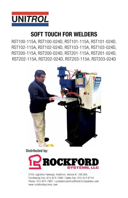
<strong>SOFT</strong> <strong>TOUCH</strong> FOR WELDERS<br />
RST100-115A, RST100-024D, RST101-115A, RST101-024D,<br />
RST102-115A, RST102-024D, RST103-115A, RST103-024D,<br />
RST200-115A, RST200-024D, RST201-115A, RST201-024D,<br />
RST202-115A, RST202-024D, RST203-115A, RST203-024D<br />
Distributed by:
Thank you for purchasing this Unitrol <strong>SOFT</strong> <strong>TOUCH</strong> system. It is designed to protect your<br />
resistance welder operator from serious electrode pinch-point injury. Please let us know<br />
if there are any questions or problems with the installation or use of this product. You<br />
can contact us:<br />
BY PHONE:<br />
Monday - Friday 8:00 - 5:00 CT: 1-800-922-7533<br />
BY EMAIL:<br />
sales@rockfordsystems.com<br />
BY REGULAR MAIL:<br />
Rockford Systems, LLC<br />
5795 Logistics Parkway<br />
Rockford, IL 61109<br />
USA<br />
2 | <strong>SOFT</strong> <strong>TOUCH</strong> FOR WELDERS
√<br />
MODEL<br />
RST100-115A<br />
RST102-115A<br />
RST101-115A<br />
RST100-024D<br />
RST101-024D<br />
RST200-115A<br />
RST201-115A<br />
RST200-024D<br />
RST201-024D<br />
RST-402<br />
RST-400<br />
RST-401<br />
RST-403<br />
RST-404<br />
RST-405<br />
RST-406<br />
RST-407<br />
RST-409<br />
RST-410<br />
RST-413<br />
WELDER TYPE &<br />
HARDWARE<br />
1Ø AC<br />
INCLUDES A SNUBBER<br />
AND 2=MUFFLERS<br />
MFDC (INVERTER)<br />
INCLUDES<br />
2=MUFFLERS<br />
RAM TYPE<br />
Heavy Weight<br />
Heavy Weight, 1” Valves<br />
Light Weight, Rocker Arm<br />
Heavy Weight<br />
Light Weight, Rocker Arm<br />
Heavy Weight<br />
Light Weight, Rocker Arm<br />
Heavy Weight<br />
Light Weight, Rocker Arm<br />
Heavy Weight<br />
Light Weight, Rocker Arm<br />
Heavy Weight<br />
VALVE<br />
VOLTAGE<br />
115AC<br />
24VDC<br />
24VAC<br />
115VAC<br />
24VDC<br />
24VAC<br />
Light Weight, Rocker Arm<br />
OPTIONS<br />
Timed bypass. Includes security lock selector switch, 2 = LED indicator<br />
lights, faceplate. Closes electrodes under low force, delays, and brings<br />
electrodes to welding force<br />
Retract Kit. Includes HEAD DOWN proximity switch and mounting bracket<br />
kit. May require additional field bracketry to match welder<br />
Retract option without proximity switch. For use with <strong>welders</strong> that have<br />
separate RETRACT and WELD INITIATION switches.<br />
Limit Switch. Allows use of ram position or continuity. Includes RAM<br />
POSITION proximity switch and mounting bracket kit. May require additional<br />
field bracketry to match welder. Includes security lock selector switch, 2 =<br />
LED indicator lights, faceplate<br />
Limit Switch. Allows use of a ram position or continuity. Includes security<br />
lock selector switch, 2 = LED indicator lights, faceplate. Does NOT include<br />
a proximity switch or mounting bracket kit. Use with customer-supplied PNP<br />
proximity switch<br />
Limit Switch used as a redundancy with continuity. Always in operation<br />
and not keylock selected. Includes RAM POSITION proximity switch and<br />
mounting bracket kit. May require additional field bracketry to match welder.<br />
Can be turned off by moving a jumper on the control board<br />
½” NPT Filter, regulator, lubricator with inter block for pilot line. With air<br />
gauge. Not needed if existing regulator is good<br />
¾” NPT Filter, regulator, lubricator with inter block for pilot line. With air<br />
gauge. Not needed if existing regulator is good<br />
Line voltage transformer and fuses for installation on TECNA welding controls<br />
Adds 50VA transformer for <strong>welders</strong> without 115VAC available<br />
System for operation on <strong>welders</strong> with FORGE DELAY<br />
<strong>SOFT</strong> <strong>TOUCH</strong> FOR WELDERS | 3
WARRANTY<br />
Unitrol Electronics provides a 5-year limited warranty to cover all of this <strong>SOFT</strong> <strong>TOUCH</strong> system. The<br />
warranty periods are determined using the date the new control was originally shipped from Unitrol<br />
Electronics. All warranty coverage is FOB Northbrook. Illinois.<br />
This warranty, except for exclusions shown herein covers the following items:<br />
DURING YEAR #1: All parts (exclusive of fuses) that fail due to manufacturing defects. Necessary<br />
labor to repair control that has failed due to manufacturing defects.<br />
DURING YEAR #2: 80% cost of all parts (exclusive of fuses).<br />
80% cost of necessary labor to repair control that has failed due to manufacturing defects.<br />
DURING YEAR #3: 60% cost of all parts (exclusive of fuses).<br />
60% cost of necessary labor to repair control that has failed due to manufacturing defects.<br />
DURING YEAR #4: 40% cost of all parts (exclusive of fuses).<br />
40% cost of necessary labor to repair control that has failed due to manufacturing defects.<br />
DURING YEAR #5:<br />
20% cost of all parts (exclusive of fuses).<br />
20% cost of necessary labor to repair control that has failed due to manufacturing defects.<br />
EXCLUSIONS TO WARRANTY<br />
Any expense involved with repair of control by other than Unitrol Electronics personnel that has not<br />
been authorized in advance and in writing by an officer of Unitrol Electronics.<br />
All costs for freight, to and from Unitrol Electronics, are excluded from this warranty<br />
All field service labor, travel expense, and field living expenses associated with field service are<br />
excluded from this warranty.<br />
No coverage, parts or labor, is offered for components that have failed on control not being used as<br />
specified in Unitrol Electronics published literature, technical sheets, and this direction book.<br />
No warranty coverage will be made on controls that are being used contrary to specifications, that<br />
were mechanically or electronically altered by customer or installer, or that were physically damaged<br />
after shipment from Unitrol Electronics.<br />
Damages to a control by lightning, flood, or mechanical damage are excluded from this warranty.<br />
Unitrol Electronics assumes no liability for damage to other equipment or injury to personnel due to<br />
a failure in the Unitrol Electronics control.<br />
Unitrol Electronics shall not be responsible for any consequential damages of whatever kind.<br />
Expenses involving alteration or installation of a Unitrol Electronics control are not covered in this warranty.<br />
NO OTHER <strong>UNITROL</strong> ELECTRONICS INC. WARRANTY, WRITTEN OR IMPLIED, COVERS THIS<br />
CONTROL UNLESS IN WRITING AND SIGNED BY AN OFFICER OF <strong>UNITROL</strong> ELECTRONICS, INC.<br />
PRIOR TO SHIPMENT OF PRODUCT.<br />
4 | <strong>SOFT</strong> <strong>TOUCH</strong> FOR WELDERS
TABLE OF CONTENTS:<br />
VERIFY YOUR <strong>SOFT</strong> <strong>TOUCH</strong> SENSOR BOARD IS CORRECT.......................................... 6<br />
HOW SYSTEM OPERATES........................................................................................... 7<br />
INSTALLATION,RST100/RST200 HEAVY WEIGHT SERIES ........................................... 8<br />
INSTALLATION, RST101/RST201 LIGHT WEIGHT SERIES ........................................... 9<br />
WIRING CONTROL: CONNECTING SIGNAL PICKUP WIRES ........................................ 10<br />
CONNECTING THE SNUBBER .................................................................................... 11<br />
CONNECTING CONTROL CABLE ................................................................................ 11<br />
CONTROL CABLE WIRING CHART ............................................................................. 12<br />
SPECIAL WIRING FOR OPTIONS RST-409 AND RST-410 .......................................... 13<br />
ELECTRICAL HOOKUP, RST100-115A, RST101-115A................................................ 14<br />
ELECTRICAL HOOKUP, RST100-024D, RST101-024D............................................... 15<br />
ELECTRICAL HOOKUP, RST100-024D, RST101-024D............................................... 16<br />
ELECTRICAL HOOKUP, RST200-115A, RST201-115A................................................ 17<br />
ELECTRICAL HOOKUP, RST200-024D, RST201-024D............................................... 18<br />
ELECTRICAL HOOKUP, RST200-024D, RST201-024D............................................... 19<br />
RETRACT OPTION RST-400..................................................................................20-21<br />
RETRACT OPTION RST-401..................................................................................22-23<br />
TIMED DELAY OPTION RST-402................................................................................ 24<br />
DEPTH SWITCH OPTION, RST-403, RST-404.......................................................25-26<br />
PNEUMATIC HOOKUP, RST101/RST201 LIGHT WEIGHT............................................ 27<br />
PNEUMATIC HOOKUP, RST100/RST200 HEAVY WEIGHT........................................... 28<br />
ADJUSTING <strong>SOFT</strong> <strong>TOUCH</strong> VALVES............................................................................ 29<br />
SETTING MAXIMUM DETECT TIME SWITCHES, BLANK TIME.................................... 30<br />
SETTING AND TESTING ELECTRODE CLOSING FORCE.............................................. 30<br />
TESTING ELECTRODE FORCE.................................................................................... 31<br />
START-UP PROCEDURE............................................................................................. 32<br />
TROUBLE SHOOTING CHART..................................................................................... 33<br />
FORCE/BUCKING PRESSURE OPTION RST-413......................................................... 34<br />
LED INDICATOR LIGHTS............................................................................................ 35<br />
<strong>SOFT</strong> <strong>TOUCH</strong> FOR WELDERS | 5
VERIFY YOUR <strong>SOFT</strong> <strong>TOUCH</strong> SENSOR BOARD IS CORRECT<br />
The <strong>SOFT</strong> <strong>TOUCH</strong> sensor board can be configured in several ways. Before turning power<br />
on, check to be sure that the mode and valve voltage matches your welder.<br />
1. TYPE OF WELDING CONTROL. This board can be set to operate either a 1ØAC welder<br />
or an MFDC (inverter) welder. This is done by pushing the three switches on the lower<br />
left corner to a position to match your welding control.<br />
FOR 1ØAC WELDERS<br />
FOR MFDC (INVERTER) WELDERS<br />
2. SOLENOID VALVE VOLTAGE. Be sure that the two tall relays, K2 and K3, show the<br />
same voltage on the top printing as the solenoid voltage of your welding control. If they<br />
are not correct, contact Unitrol to swap relays.<br />
FOR 115VAC SOLENOID VALVES<br />
FOR 24VDC SOLENOID VALVES<br />
3. SPECIAL INITIATION SCHEMES. Some Tecna <strong>welders</strong><br />
do not have a pressure switch input and use a normally<br />
CLOSED switch that OPENS when the second stage<br />
of the footswitch is pushed. For these <strong>welders</strong>, move<br />
Jumper JP6 (next to the transformer) to the NC position<br />
and connect output terminals in parallel to the second<br />
stage Normally-Closed footswitch contact.<br />
For Tecna <strong>welders</strong>, connect output #6 on sensor board<br />
Tecna START NO terminal, and wire from #7 on sensor<br />
board to Tecna AUX terminal to put this in parallel to the<br />
footswitch second stage.<br />
6 | <strong>SOFT</strong> <strong>TOUCH</strong> FOR WELDERS<br />
NORMAL<br />
POSITION<br />
TECNA<br />
POSITION
<strong>SOFT</strong> <strong>TOUCH</strong> PINCH POINT PROTECTION SYSTEM FOR INSTALLATION<br />
ON NON-<strong>UNITROL</strong> 1Ø AC AND MFDC WELDING CONTROLS<br />
HOW THE SYSTEM OPERATES<br />
When the solenoid valve output from the welding control goes HIGH, this voltage goes to<br />
the 9280-TS6 <strong>SOFT</strong> <strong>TOUCH</strong> detection board, terminal #9.<br />
The output terminal #11 (SVL) goes HIGH to turn on solenoid valve SVL.<br />
For RST100 systems, this closes the welding electrodes under gravity force with low<br />
force bucking pressure (BALANCE) acting on the underside of the cylinder piston to<br />
counterbalance part of the ram dead weight.<br />
For RST101 systems, this closes the welding electrodes under low force (CLOSE) using<br />
low air pressure on the forward port of the welder cylinder.<br />
The 9280-TS6 board checks input at terminals #4 and #5 to see if the voltage signal<br />
drops a minimum value indicating that the electrodes have made contact on a conducting<br />
material (continuity detected).<br />
If this contact is NOT sensed within the maximum time setting on the board’s DIPswitches,<br />
the output terminal #11 (SVL) will go LOW and drop out solenoid valve SVL to open the<br />
electrodes.<br />
If this contact IS sensed within the maximum time setting:<br />
• Terminal #11 (SVL) will continue to be HIGH<br />
• Terminal #13 (SVH) will go HIGH<br />
• Solenoid valve SVH will be turned ON to start high electrode pressure, and relay K4<br />
on this board will close to start the welding sequence<br />
• The contact across terminals #6 and #7 on the TS2 board close to tell the welding<br />
control to start the welding sequence.<br />
<strong>SOFT</strong> <strong>TOUCH</strong> FOR WELDERS | 7
INSTALLATION<br />
Note that this system REPLACES the existing weld solenoid valve.<br />
1. Mount the control in a convenient location using the four mounting tabs on the back<br />
of the box.<br />
2. Remove hoses from the existing welding solenoid valve. This solenoid valve will not<br />
be used with this control.<br />
3. Connect hoses from the control to the air cylinder as shown in the photos below<br />
and the next page. Choose the photo that matches your control model.<br />
HOSE CONNECTION FOR RST100/RST200 SERIES CONTROL<br />
Note that this system REPLACES the existing weld solenoid valve.<br />
TOP OF CABINET<br />
Install filters on bottom of cabinet<br />
To existing<br />
retract valve<br />
input for<br />
RST400/<br />
RST401<br />
Options<br />
Connect to air cylinder port<br />
that closes the electrodes<br />
Connect to point between air<br />
filter/water trap and input to<br />
welding pressure regulator<br />
Connect to point<br />
after airline oiler<br />
(weld pressure)<br />
Connect to air cylinder port<br />
that opens the electrodes<br />
BOTTOM OF CABINET<br />
Connect to air cylinder port<br />
that opens the electrodes<br />
Connect to point between air<br />
filter/water trap and input to<br />
welding pressure regulator<br />
Connect to point<br />
after airline oiler<br />
(weld pressure)<br />
Connect to air cylinder port<br />
that closes the electrodes<br />
8 | <strong>SOFT</strong> <strong>TOUCH</strong> FOR WELDERS
HOSE CONNECTION FOR RST101/RST201 SERIES CONTROLS<br />
Note that this system REPLACES the existing weld solenoid valve.<br />
TOP OF CABINET<br />
Install filters on bottom of cabinet<br />
For RST400/<br />
RST401<br />
options<br />
to existing<br />
RETRACT<br />
valve input<br />
Connect to point<br />
after airline oiler<br />
(weld pressure)<br />
Connect to air cylinder port<br />
that closes the electrodes<br />
Connect to air cylinder port<br />
that opens the electrodes<br />
Connect to point between air<br />
filter/water trap and input to<br />
welding pressure regulator<br />
BOTTOM OF CABINET<br />
Connect to point between air<br />
filter/water trap and input to<br />
welding pressure regulator<br />
Connect to air cylinder port<br />
that closes the electrodes<br />
Connect to point<br />
after airline oiler<br />
(weld pressure)<br />
Connect to air cylinder port<br />
that opens the electrodes<br />
<strong>SOFT</strong> <strong>TOUCH</strong> FOR WELDERS | 9
WIRING CONTROL CONNECTING SIGNAL PICKUP WIRES<br />
Note that this system REPLACES the existing weld solenoid valve.<br />
1. Connect the TWO BLUE WIRES from the bottom of the box to the upper and lower<br />
secondary pad on the welding transformer or any point close to the pad. See photos<br />
below for suggested areas for various types of <strong>welders</strong>.<br />
CRITICAL: BE SURE THAT THE SURFACE UNDER EACH TERMINAL IS CLEAN, AND<br />
THAT THE SCREWS ARE FULLY TIGHTENED. OPERATIONAL PROBLEMS WILL OCCUR<br />
IF THIS CONNECTION IS NOT GOOD.<br />
10 | <strong>SOFT</strong> <strong>TOUCH</strong> FOR WELDERS
WIRING CONTROL CONNECTING SNUBBER<br />
2. FOR RST100 AND RST101 MODELS, Connect blue snubber cylinder in this kit across<br />
the SCR contactor per the HOOK-UP drawing and typical photos below. It does not<br />
matter which wire from the snubber connects to which side of the SCR contactor.<br />
NOTE: If the welding control already has a snubber or a resistor in series with a<br />
capacitor wired across the SCR contactor, remove it. There should only be the new<br />
blue snubber installed across the SCR contactor.<br />
CONNECTING CONTROL CABLE<br />
3. Route the black multi-wire cable from the top of the <strong>SOFT</strong> <strong>TOUCH</strong> enclosure to the<br />
welding control.<br />
4. Install the supplied strain relief fitting in a 7/8” diameter hole in the welding control<br />
and bring cable into the control.<br />
5. Trim the cable to allow it to reach the terminals shown in the table on the next<br />
page. Wire as shown.<br />
NOTE: Check the Unitrol web site www.unitrol-electronics.com SUPPORT tab for<br />
hookup charts for some popular welding controls.<br />
<strong>SOFT</strong> <strong>TOUCH</strong> FOR WELDERS | 11
WIRING CONTROL, CONTROL CABLE WIRING CHART<br />
WIRE COLOR<br />
TS7<br />
TERM<br />
CONNECT IN WELDING<br />
CONTROL FOR<br />
24VDC MODELS<br />
RST100-024D,<br />
RST200-024D<br />
RST101-024D<br />
RST201-024D<br />
CONNECT IN WELDING<br />
CONTROL FOR<br />
115VAC MODELS<br />
RST100-115A,<br />
RST200-115A<br />
RST101-115A<br />
RST201-115A<br />
BLACK 1 115VAC L 115VAC L<br />
WHITE 2 115VAC N 115VAC N<br />
RED/BLACK ST. 6 INIT. PERMISSION1 INIT. PERMISSION1<br />
RED 7 INIT. PERMISSION1 INIT. PERMISSION1<br />
FOR CONTROLS<br />
SWITCHED WITH<br />
+24VDC 2<br />
FOR<br />
CONTROLS<br />
SWITCHED<br />
WITH 0VDC 3<br />
BLUE 14 24VDC + 24VDC 0V<br />
115VAC = NOT USED<br />
24VAC = 24VAC L<br />
WHITE/BLACK ST. 23 24VDC 0V 24VDC<br />
115VAC = NOT USED<br />
24VAC = 24V N<br />
ORANGE 9*<br />
WELD CONTROL SOLENOID VALVE<br />
OUTPUT 4<br />
115VAC L SOLENOID VALVE<br />
DRIVER OUTPUT 2<br />
GREEN - GROUND STUD GROUND STUD<br />
USED ONLY WITH RETRACT OPTIONS RST-400 OR RST-401<br />
GREEN/BLACK ST. 18 RETRACT IN SIGNAL 4 RETRACT IN SIGNAL4<br />
1. INIT. PERMISSION is either a PRESSURE SWITCH input terminal or in series with<br />
FOOTSWITCH second stage. These wires connect to a dry contact relay.<br />
2. Welding controls that use +24VDC to operate the welding (and RETRACT if<br />
applicable) solenoid valve.<br />
3. Welding controls that use 0VDC to operate the welding (and RETRACT if applicable)<br />
solenoid valve.<br />
4. The potential of this output should be the same as the voltage on terminal #14<br />
(BLUE wire).<br />
CAUTION: INCORRECT CONNECTION WILL CAUSE SEVERE DAMAGE.<br />
12 | <strong>SOFT</strong> <strong>TOUCH</strong> FOR WELDERS
FOR OPTIONS TECNA AND RST-410<br />
Connect jumper on primary to match line voltage. Connect the white and black<br />
wires from the cable to THAT LINE VOLTAGE IN THE WELDING CONTROL<br />
FOR 440V POWER<br />
JUMP H2 + H3<br />
FOR 220V POWER<br />
JUMP H1 + H3<br />
JUMP H2 + H4<br />
<strong>SOFT</strong> <strong>TOUCH</strong> FOR WELDERS | 13
INSTALLATION HOOK-UP DRAWING<br />
RST100-115A, RST101-115A<br />
14 | <strong>SOFT</strong> <strong>TOUCH</strong> FOR WELDERS
INSTALLATION HOOK-UP DRAWING<br />
RST100-024D, RST101-024D<br />
<strong>SOFT</strong> <strong>TOUCH</strong> FOR WELDERS | 15
INSTALLATION HOOK-UP DRAWING<br />
RST100-024D, RST101-024D<br />
16 | <strong>SOFT</strong> <strong>TOUCH</strong> FOR WELDERS
INSTALLATION HOOK-UP DRAWING<br />
RST200-115A, RST201-115A<br />
<strong>SOFT</strong> <strong>TOUCH</strong> FOR WELDERS | 17
INSTALLATION HOOK-UP DRAWING<br />
RST200-024D, RST201-024D<br />
18 | <strong>SOFT</strong> <strong>TOUCH</strong> FOR WELDERS
INSTALLATION HOOK-UP DRAWING<br />
RST200-024D, RST201-024D<br />
<strong>SOFT</strong> <strong>TOUCH</strong> FOR WELDERS | 19
OPTIONAL RETRACT WITH <strong>SOFT</strong> <strong>TOUCH</strong> RST-400<br />
FOR WELDERS WITH A RETRACT TYPE CYLINDER. OPERATED BY A 3-SECTION<br />
FOOT SWITCH<br />
This type of foot switch has the RETRACT switch controlled as the first level and mechanically<br />
latched. The other two levels of this foot switch operate the welding sequence.<br />
This option protects against pinch point injury when bringing the electrodes from fully<br />
open RETRACT position to the WORK position (small space between electrodes). The<br />
option includes a PNP proximity switch that is adjusted to go high when the retract cylinder<br />
is fully bottomed putting the electrodes in the (small opening) WORK position.<br />
1. Install the PNP proximity switch using the starter bracket kit in this option. Modify as<br />
necessary to work with your welder. The proximity switch has to be blocked when<br />
the ram is down in the WORK (small opening) position. This will put 24VDC into<br />
terminal 26.<br />
2. Wire the PNP proximity switch as shown below.<br />
3. Move the double RETRACT jumper<br />
plug to the RETRACT (upper) position<br />
as shown. This is located on the upper<br />
left corner of the board<br />
20 | <strong>SOFT</strong> <strong>TOUCH</strong> FOR WELDERS
OPTIONAL RETRACT WITH <strong>SOFT</strong> <strong>TOUCH</strong> RST-400 (CONTINUED)<br />
3. Connect the 3-stage foot switch as shown below.<br />
See bottom of page 17 for pneumatic hookup for this option<br />
<strong>SOFT</strong> <strong>TOUCH</strong> FOR WELDERS | 21
OPTIONAL RETRACT WITH <strong>SOFT</strong> <strong>TOUCH</strong> RST-401<br />
This option RST-401 is for RETRACT that operates from either RETRACT VOLTAGE<br />
from the welding control or from a separate RETRACT foot switch.<br />
DO NOT USE THIS OPTION FOR WELDERS THAT USE A COMMON WELD AND<br />
RETRACT FOOT SWITCH (use RST-400)<br />
HOOKUP FOR SYSTEMS USING RETRACT VOLTAGE SIGNAL FROM THE<br />
WELDING CONTROL:<br />
Remove the existing wire from the welding control RETRACT valve driver terminal and wire<br />
as shown below to terminal #18<br />
22 | <strong>SOFT</strong> <strong>TOUCH</strong> FOR WELDERS
OPTIONAL RETRACT WITH <strong>SOFT</strong> <strong>TOUCH</strong> RST-401<br />
Insert a jumper from terminal 26 to terminal 29. Note that the HEAD DOWN LIM. SW light<br />
on the annunciator panel will be on permanently when this jumper is in place.<br />
<strong>SOFT</strong> <strong>TOUCH</strong> FOR WELDERS | 23
OPTIONAL TIMED DELAY RST-402<br />
Some materials being welded have coatings or other<br />
conditions that prevent good continuity between electrodes.<br />
For these conditions option #RST-402 will all ow the welder<br />
to be operated using TIMING rather than CONTINUITY to<br />
switch from low force to high welding force. In this case, the<br />
low force will be applied for the time set on the 4-position<br />
DETECT TIME DIPswitch, and then the high welding force<br />
will turn on. The time from initiation to high force is the SUM<br />
of the switches pushed down on top.<br />
CAUTION: When the key switch is in the TIMED<br />
position, the HIGH WELDING FORCE will turn on after<br />
the selected delay (detect) time unless initiation is<br />
opened. This will happen even if a non-conductive<br />
material or body part is between the electrodes.<br />
This option will be factory wired and supplied with the faceplate.<br />
24 | <strong>SOFT</strong> <strong>TOUCH</strong> FOR WELDERS
OPTIONAL DEPTH SWITCH RST-403, RST-404<br />
This option allows use of either CONTINUITY DETECTION or closure of a DEPTH SWITCH<br />
to turn on the weld pressure and start the weld sequence. It is useful when parts being<br />
welded have a non-conductive coating.<br />
INSTALLATION:<br />
RST-403: Mount the PNP proximity switch that is supplied with this option on the body of<br />
the welder using the mounting bar. Modify and bend as needed<br />
RST-404: Mount a customer-supplied mechanical limit switch or PNP proximity switch on<br />
the body of the welder.<br />
BOTH: Make and install an adjustable cam on the moving part of the welder that will go in<br />
front of this switch when the upper electrode are less than 1/4” from the lower electrode.<br />
NOTE: If the parts being welded are very thick, setting the DEPTH SWITCH to close<br />
when there is a 1/4” gap between electrodes might not work when the part being<br />
welded is in place. In this case, set the DEPTH SWITCH to close when there is 1/4”<br />
gap from the TOP OF THE PART being welded to the underside of the upper electrode.<br />
To protect from pinch point injury when a part is NOT between the electrodes, adjust<br />
the electrode holders so that the air cylinder will bottom out when the gap between<br />
electrodes is 1/4”.<br />
<strong>SOFT</strong> <strong>TOUCH</strong> FOR WELDERS | 25
OPTIONAL DEPTH SWITCH RST-403 , RST-404 (CONTINUED)<br />
Wire the switch to match the appropriate hookup below.<br />
USE IN PRODUCTION:<br />
Turn the key COUNTER-CLOCKWISE to the CONTINUITY position. The yellow panel<br />
indicator will glow. In this position, high welding pressure will only be applied when<br />
electrical continuity is detected between the upper and lower electrodes.<br />
Turn the key CLOCKWISE to the DEPTH SWITCH position. The red panel indicator will<br />
glow. After initiation, the electrodes will close with low force. If the DEPTH SWITCH closes<br />
before the maximum DETECT TIME (as set on the DIPswitch) has been reached, the LIMIT<br />
SWITCH CLOSED light will glow on the annunciator panel, electrodes will go to welding<br />
force, and the output of the sensor board will close to start the welding control.<br />
CAUTION: When the key switch is in the DEPTH<br />
SWITCH position, the HIGH WELDING FORCE will<br />
turn on after the DEPTH SWITCH is closed. This will<br />
happen even if a non-conductive material or body<br />
part is between the electrodes.<br />
26 | <strong>SOFT</strong> <strong>TOUCH</strong> FOR WELDERS
PNEUMATIC HOOKUP<br />
RST101/RST201 LIGHT RAM OR ROCKER ARM WELDERS CONNECT HOSES TO<br />
PORTS SHOWN RED BELOW<br />
<strong>SOFT</strong> <strong>TOUCH</strong> FOR WELDERS | 27
PNEUMATIC HOOKUP<br />
RST100/RST200 HEAVY WEIGHT RAM WELDERS CONNECT HOSES TO PORTS<br />
SHOWN IN RED BELOW<br />
28 | <strong>SOFT</strong> <strong>TOUCH</strong> FOR WELDERS
ADJUSTING THE <strong>SOFT</strong> <strong>TOUCH</strong> VALVE SYSTEM<br />
F0R RST100 SERIES CONTROLS - HEAVY WEIGHT RAMS<br />
1. The ADVANCE PRESSURE puts air on the underside of the air cylinder piston to LIFT<br />
the welder ram. This is used to partially lower the force between the electrodes due to the<br />
dead (gravity) weight of the welder’s ram. Increasing this ADVANCE PRESSURE value will<br />
decrease the force between the electrodes when closed under low force.<br />
2. BE SURE THAT ALL FLOW CONTROL VALVES HAVE BEEN REMOVED FROM THE<br />
WELDER CYLINDER BEFORE DOING ANY ADJUSTMENT OF THIS SYSTEM.<br />
3. Set the BALANCE pressure regulator inside the enclosure so that the BALANCE<br />
PRESSURE gauge on the door is at approximately 1psi.<br />
4. Set the OPEN pressure regulator inside the enclosure so that the OPEN PRESSURE<br />
gauge on the door is at approximately 12 psi.<br />
5. Turn the TIP DRESS switch ON. The electrodes should close. Check the force<br />
between the electrodes and INCREASE the BALANCE pressure slightly if the force is great<br />
enough to crush a wood pencil more than 1/16” in depth. If the electrodes do not close,<br />
DECREASE the BALANCE pressure to as low as 0 psi. Even though the pressure gauge<br />
shows 0psi, this pressure is actually 1/2psi.<br />
6. Adjust the OPEN pressure regulator so that when the TIP DRESS switch is OFF, the<br />
electrodes open smoothly. Use the LOWEST setting on the OPEN pressure regulator that<br />
will smoothly open the electrodes. This will produce the fastest electrode closing time.<br />
F0R RST101 SERIES CONTROLS - LIGHT WEIGHT RAMS AND ROCKER ARM WELDERS<br />
1. Set the CLOSE pressure regulator inside the enclosure so that the CLOSE PRESSURE<br />
gauge on the door is at approximately 3psi.<br />
2. Set the OPEN pressure regulator inside the enclosure so that the OPEN PRESSURE<br />
gauge on the door is at approximately 12 psi.<br />
3. Turn the TIP DRESS switch ON. The electrodes should close. If they don’t,<br />
INCREASE the CLOSE pressure regulator. Check the force between the electrodes and<br />
DECREASE this pressure slightly if the force is great enough to crush a wood pencil<br />
more than 1/16” in depth.<br />
4. Adjust the OPEN pressure regulator so that when the TIP DRESS switch is OFF, the<br />
electrodes open smoothly. Use the LOWEST setting on this OPEN pressure regulator that<br />
will smoothly open the electrodes. This will produce the fastest electrode closing time.<br />
<strong>SOFT</strong> <strong>TOUCH</strong> FOR WELDERS | 29
SETTING <strong>SOFT</strong> <strong>TOUCH</strong> BOARD MAXIMUM DETECT TIME SWITCHES<br />
Locate the four-section ADD FOR DETECT TIME DIPswitch on the left side of each <strong>SOFT</strong><br />
<strong>TOUCH</strong> board. This switch is marked: 1, .75, .5, and .25 seconds. Set the switches to a<br />
value that is about 2 times how long it will take for the electrodes to close. The on-board<br />
computer adds the value of these switches. For example, pushing 1 and .5 down to the<br />
left side will produce a detection time of 1.5 seconds. This setting is not critical. A typical<br />
setting is 1 second. Longer times might be needed for very long stroke cylinders<br />
For example, in the photo below the 0.25 and 1 switch is pushed down toward the top of<br />
the board for a total maximum detect time of 1.25 seconds.<br />
DETECT BLANK TIME<br />
After the <strong>SOFT</strong> <strong>TOUCH</strong> board is initiated, the system will not<br />
look for continuity until the DETECT BLANK TIME has been<br />
reached. This time is 50% of the time you set on the ADD<br />
FOR DETECT TIME DIPswitch.<br />
TESTING THE BASIC PNEUMATIC SYSTEM<br />
1. Clean electrodes on welder<br />
2. With nothing between electrodes, close electrodes by turning ON the TIP DRESS<br />
switch at the bottom of the annunciator panel.<br />
3. The electrodes should close.<br />
4. Turn OFF the TIP DRESS switch and the electrodes will open.<br />
30 | <strong>SOFT</strong> <strong>TOUCH</strong> FOR WELDERS
SETTING AND TESTING ELECTRODE CLOSING FORCE<br />
Turn power on to <strong>SOFT</strong> <strong>TOUCH</strong> system.<br />
Adjust the pneumatic system to produce safe closing electrode closing force using the<br />
directions on page 22 or 23 to match the model number of this <strong>SOFT</strong> <strong>TOUCH</strong> system.<br />
Use the TIP DRESS switch to close the electrodes each time you make a change in the<br />
pressure regulator settings. A successful pneumatic setting will provide a force under 50<br />
pounds between the electrodes. There are two methods to check this force:<br />
1. The most precise method is to use a tip force measuring instrument between<br />
the electrodes. This produces data that can be recorded on safety records and is less<br />
subjective to visual observation. Unfortunately most of these devices do not have any<br />
accuracy in the low force ranges. Do not use an instrument that has poor or unknown<br />
accuracy in the low force range. An excellent device that can read the low forces is<br />
Tuffaloy model 601-3000DLC. This unit can also be used to read welding forces up to<br />
3,000 pounds.<br />
2. Place a wood pencil between the electrodes and close using the TIP DRESS switch.<br />
The electrodes should not dent more than 1/16” into either side. A typical #2 wood office<br />
pencil works well. A carpenter’s pencil works better since the flat area is much larger.<br />
<strong>SOFT</strong> <strong>TOUCH</strong> FOR WELDERS | 31
STARTUP PROCEDURE<br />
1. Turn on power to welding control.<br />
2. The <strong>SOFT</strong> <strong>TOUCH</strong> annunciator panel should go through a test procedure and then the<br />
READY LED should turn on solidly.<br />
3. If the READY LED does flashes slowly or quickly see the trouble shooting section in<br />
this direction book.<br />
4. The system should be ready for operation. There is no customer calibration needed<br />
now or ever.<br />
SUCCESSFUL SEQUENCE<br />
WITHOUT LIMIT SWITCH<br />
1. Weld control sends voltage to<br />
terminal 9 (SV).<br />
2. START lights<br />
3. Low Force solenoid valve (SVL) is<br />
energized, Low Force ON LED lights.<br />
4. Electrodes close<br />
5. Continuity is detected and CONTINUITY<br />
DETECTED LED lights.<br />
6. High Force solenoid valve (SVH) is<br />
energized, HIGH FORCE ON LED lights.<br />
7. Output relay at terminals 6 & 7 closes<br />
to start weld control sequence, and OK<br />
TO WELD LED lights.<br />
UNSUCCESSFUL SEQUENCE<br />
If continuity is not detected within the maximum time set on the DIPswitch, electrodes<br />
will not get to welding force, will open, and the Detect Time Exceeded, Dress Electrodes<br />
LED will light. Clean the electrodes and try the sequence again. Or check to see if the<br />
DIPswitch on the board is set to a long enough time to allow for the electrodes to close.<br />
32 | <strong>SOFT</strong> <strong>TOUCH</strong> FOR WELDERS
TROUBLE SHOOTING CHART<br />
NOTE: This <strong>SOFT</strong> <strong>TOUCH</strong> system will not operate if any fault is detected.<br />
SYSTEM READY LED will glow solidly if all faults are cleared.<br />
INDICATION CAUSE WHAT TO CHECK OR DO<br />
READY LED not on<br />
READY LED is on but is<br />
FLASHING<br />
Electrodes will not close<br />
when welding control is<br />
initiated<br />
READY LED flashing SLOWLY.<br />
Electrodes will not close<br />
when welding control is<br />
initiated.<br />
OR<br />
CONTINUITY DETECTED<br />
WITH NO START SIGNAL LED<br />
on when electrodes are not<br />
<strong>touch</strong>ing.<br />
READY LED flashing QUICKLY<br />
DETECT TIME EXCEEDED.<br />
DRESS ELECTRODES LED<br />
flashing<br />
OUTPUT CLOSED FAULT<br />
LED is on<br />
No power to control<br />
One fault shown below is<br />
detected<br />
The READY LED will not glow<br />
SOLIDLY until the system has<br />
cleared all faults<br />
Voltage on blue sensor wires<br />
is too low<br />
Lowering of this voltage is<br />
used by the sensor board<br />
to detect when continuity is<br />
reached<br />
Insulator missing or some<br />
conducting component<br />
is connected between<br />
insulated side of welder<br />
secondary and welder frame.<br />
Voltage on blue sensor wires<br />
is too high<br />
Not enough time allowed to<br />
close electrodes<br />
Electrodes not making good<br />
contact.<br />
Electrodes do not <strong>touch</strong><br />
when welder air cylinder is<br />
fully extended.<br />
Output relay K4 is<br />
mechanically closed<br />
(welded contacts)<br />
Be sure that 115V is at terminals #1 and #2<br />
Voltage from welding control valve driver output connected to<br />
terminals 8 and 9 on the sensor board is on when power is<br />
turned on to the <strong>soft</strong> <strong>touch</strong> system<br />
correct weld control<br />
SEE ITEMS TO CHECK ON BOXES BELOW<br />
Be sure that the two blue pickup wires coming from the<br />
cabinet are correctly connected to welder secondary.<br />
See page 5<br />
FOR MFDC INVERTER WELDERS: Be sure that all three<br />
switches on lower left of board are set to the MFDC position.<br />
See page 1<br />
FOR 1Ø AC WELDERS:<br />
1.Be sure that all three switches on lower left of the sensor<br />
board are set to the AC position.<br />
See page 1.<br />
2.Be sure that a snubber is installed correctly.<br />
See page 6.<br />
3.Measure AC voltage at TP2 - TP3. It should be a minimum<br />
of 25mv (.025V). If it is above zero but below 25mv, a second<br />
snubber might have to be added across the SCR to bring this<br />
voltage up.<br />
4.If it is 0mv, replace the snubber. See page 1.<br />
CHECK MECHANICAL SYSTEM. Disconnect flexible shunt that<br />
connects weld transformer secondary to moving arm, pull<br />
out plug on <strong>SOFT</strong> <strong>TOUCH</strong> board at SOC2 (terminals 4 to 7).<br />
Measure resistance between electrodes. If it is not 0, check<br />
for bad insulator or some other path between the insulated<br />
moving welder part and the welder frame. Repair or replace<br />
as needed.<br />
Contact Unitrol service for instructions<br />
Increase DIPswitch time. Remember that this maximum time<br />
is the SUM of all switches pushed down towards the time<br />
numbers (.25sec, .5 sec, .75sec, 1 sec)<br />
Clean electrodes or check part being welded.<br />
Adjust electrode holders so that there is at least a 1/4” left in<br />
the air cylinder travel when the electrodes <strong>touch</strong>.<br />
Replace KA relay<br />
<strong>SOFT</strong> <strong>TOUCH</strong> FOR WELDERS | 33
OPTION RST-413 FORGE/BUCKING PRESSURE OPTION<br />
This option brings electrodes closed under low force. After continuity is detected, the<br />
return port on the air cylinder changes pressure to that set on the existing FORGE BACKUP<br />
pressure regulator.<br />
34 | <strong>SOFT</strong> <strong>TOUCH</strong> FOR WELDERS
<strong>SOFT</strong> <strong>TOUCH</strong> SENSOR BOARD TS6 AND TS7<br />
INDICATOR LIGHTS<br />
NOTE: TS-5 BOARDS,<br />
LED6,7,8,9,14, AND 15<br />
ARE ALL GREEN<br />
6<br />
7<br />
5<br />
4<br />
3<br />
2<br />
1<br />
8<br />
9<br />
10<br />
11<br />
12<br />
13<br />
14<br />
15 16 17 18<br />
1<br />
2<br />
3<br />
4<br />
5<br />
6<br />
7<br />
8<br />
9<br />
10<br />
11<br />
12<br />
LED9 (ORANGE): is on when START FROM WELD<br />
SOL input is hight<br />
LED15 (WHITE): is on when HEAD DOWN LIM.<br />
SW. contact is closed<br />
LED8 (BLUE): is on when RETRACT VALVE ON<br />
input is high or RETR. FOOT SWITCH contact is<br />
closed<br />
LED14 (GREEN): is on when RETR. FOOT<br />
SWITCH contact is closed<br />
LED6 (YELLOW): is on when ELECTR. CLOSED<br />
LIM. SW. contact is closed<br />
LED7 (RED): is on when SELECT SWITCH INPUT<br />
contact is closed<br />
100MA FUSE for 24VIS isolated voltage; used for<br />
outside switches<br />
LED2 (ORANGE): 24VIS isolated voltage; used for<br />
outside switches<br />
LED5 (ORANGE): 24VDC used for electronic<br />
circuitry on this board<br />
LED3 (ORANGE): +15VDC<br />
LED4 (ORANGE): -15VDC<br />
LED1 (ORANGE): +5VDC<br />
13<br />
14<br />
15<br />
16<br />
17<br />
18<br />
LED16 (WHITE): high gain amplifier is on<br />
FOR AC UNITS: indicates that sensor input voltage<br />
is under 300mV<br />
For MFDC UNITS: this is the normal condition<br />
LED17 (RED): K1 spurious operation relay is<br />
energized<br />
WINDOW TURNS RED when START FROM WELD<br />
SOL. input voltage is high<br />
LED13 (RED): OUTPUT N.O. CONTACT is closed<br />
Contact closure tells control to start weld sequence<br />
JP5 IN “STD”: LED will be off during standby and<br />
turn on at continuity<br />
JP5 IN “S2”: LED will be on during standby, off<br />
after SV input, and on when continuity is detected<br />
LED512 (BLUE): OUTPUT N.O. CONTACT is open<br />
JP5 IN “STD”: this is the normal standby condition<br />
JP5 IN “S2”: this will be off until SV input, then will<br />
be on until continuity is detected<br />
WINDOW TURNS RED when RETRACT VALVE<br />
ON input is high or RETR. FOOT SWITCH contact<br />
is closed<br />
<strong>SOFT</strong> <strong>TOUCH</strong> FOR WELDERS | 35
Manufactured By:<br />
702 Landwehr Road, Northbrook, Illinois 60062 USA<br />
techsupport@unitrol-electronics.com | 847-480-0115<br />
Distributed By:<br />
RSUSTW0619


