

Installation Instructions for GHB/GDB Molded Case Circuit Breakers
Installation Instructions for GHB/GDB Molded Case Circuit Breakers
Installation Instructions for GHB/GDB Molded Case Circuit Breakers

Create successful ePaper yourself
Turn your PDF publications into a flip-book with our unique Google optimized e-Paper software.
Instruction Leaflet IL15547D<br />
Effective January 2011<br />
Supersedes IL15547C 9/02<br />
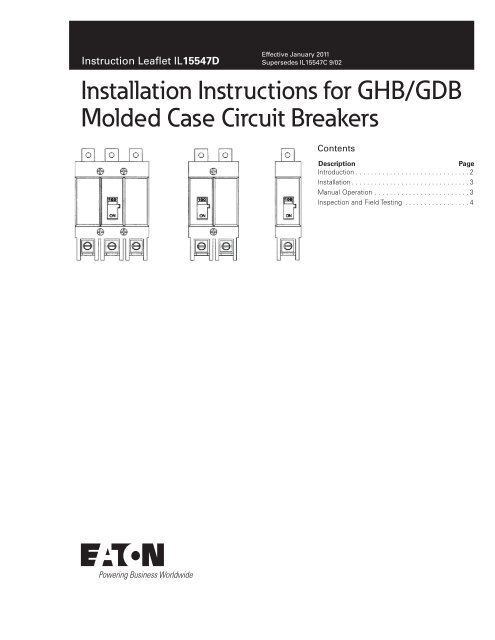
<strong>Installation</strong> <strong>Instructions</strong> <strong>for</strong> <strong>GHB</strong>/<strong>GDB</strong><br />
<strong>Molded</strong> <strong>Case</strong> <strong>Circuit</strong> <strong>Breakers</strong><br />
Contents<br />
Description Page<br />
Introduction. . . . . . . . . . . . . . . . . . . . . . . . . . . . . . . 2<br />
<strong>Installation</strong>. . . . . . . . . . . . . . . . . . . . . . . . . . . . . . . . 3<br />
Manual.Operation. . . . . . . . . . . . . . . . . . . . . . . . . . 3<br />
Inspection.and.Field.Testing . . . . . . . . . . . . . . . . . . 4
Instruction.Leaflet.IL15547D<br />
Effective January 2011<br />
2<br />
WARNING<br />
DO NOT ATTEMPT TO INSTALL OR PERFORM<br />
MAINTENANCE ON EQUIPMENT WHILE IT IS<br />
ENERGIZED. SEVERE PERSONAL INJURY,<br />
DEATH, OR SUBSTANTIAL PROPERTY DAMAGE<br />
CAN RESULT FROM CONTACT WITH ENERGIZED<br />
EQUIPMENT. ALWAYS VERIFY THAT NO<br />
VOLTAGE IS PRESENT BEFORE PROCEEDING<br />
WITH THE TASK, AND ALWAYS FOLLOW<br />
GENERALLY ACCEPTED SAFETY PROCEDURES.<br />
EATON IS NOT LIABLE FOR THE MISAPPLICATION<br />
OR MISINSTALLATION OF ITS PRODUCTS.<br />
The user is cautioned to observe all recommendations<br />
warnings, and cautions relatingto the safety of<br />
personnel and equipment, as well as, all general and<br />
local health and safety laws, codes, and procedures.<br />
The recommendations and in<strong>for</strong>mation contained<br />
herein are based on Eaton experience and judgment,<br />
but should not be consideredto be all-inclusive<br />
or covering every application or circumstance which<br />
may arise. If any questions arise, contact Eaton<br />
<strong>for</strong> further in<strong>for</strong>mation or instructions.<br />
EATON CORPORATION www.eaton.com<br />
<strong>Installation</strong> <strong>Instructions</strong> <strong>for</strong> <strong>GHB</strong>/<strong>GDB</strong><br />
<strong>Molded</strong> <strong>Case</strong> <strong>Circuit</strong> <strong>Breakers</strong><br />
1. Introduction<br />
<strong>GHB</strong> circuit breakers (Fig. 1-1) (hereafter referred<br />
to as circuit breaker) are thermal-magnetic 1, 2 and<br />
3 pole devices available in ratings from 15A to 100A<br />
continuous current. The <strong>GDB</strong> circuit breakers (fig.<br />
1-1)(hereafter referred to as circuit breaker ) are<br />
thermal-magnetic 2 and 3 pole devices available<br />
in ratings only from 15A to 50A continuous<br />
current <strong>for</strong> the 2 pole and from 15A-100A continuous<br />
current <strong>for</strong> the 3 pole. These circuit breakers are<br />
listed in accordance with Underwriters Labor-<br />
atories, Inc. Standard UL 489 (Procedure E7819),<br />
Volume B), Canadian Standards Association<br />
(LR43556), and satisfy the (Pl) requirements<br />
of the International Electrotechnical Commission<br />
Standard No. IEC 157-1.<br />
Only the <strong>GHB</strong> <strong>Circuit</strong> <strong>Breakers</strong> are designed<br />
<strong>for</strong> use with Eaton power line 2 type panelboards<br />
or equivalent.<br />
The following accessories are availabel <strong>for</strong> use with<br />
<strong>GHB</strong>/<strong>GDB</strong> circuit breakers:<br />
Fig. 1-1 <strong>GHB</strong> 1,2 and 3 Pole <strong>Circuit</strong> <strong>Breakers</strong> and <strong>GDB</strong> 2 and 3 Pole <strong>Circuit</strong> <strong>Breakers</strong>.<br />
Auxiliary Switch<br />
Alarm (signal)/Lockout Switch<br />
Shunt Trip<br />
Undervoltage Release Mechanism<br />
Lock Dog (S# 1294C01H01)<br />
Padlockable Handle (S# 1223C77G03, <strong>for</strong> 1 Pole only)
<strong>Installation</strong> <strong>Instructions</strong> <strong>for</strong> <strong>GHB</strong>/<strong>GDB</strong><br />
<strong>Molded</strong> <strong>Case</strong> <strong>Circuit</strong> <strong>Breakers</strong><br />
2.. <strong>Installation</strong><br />
The installation procedure consists of inspection and<br />
mounting the circuit breaker, connectionand torquing<br />
the terminations. To install the circuit breaker, per<strong>for</strong>m<br />
the following steps.<br />
Note: <strong>GHB</strong>/<strong>GDB</strong> circuit breakers are factory<br />
sealed.Underwriters Laboratories, Inc. Standard<br />
requires that internal accessories be installed at<br />
thefactory. Where local codes and standards<br />
permit and UL listing is not required, internal<br />
accessories can be field installed. Accessory<br />
installation should be done be<strong>for</strong>e the circuit<br />
breaker is mounted and connected.<br />
2-1. Make sure that the circuit breaker is suitable <strong>for</strong><br />
the intended installation by comparing nameplate data<br />
with system requirements. Inspect the circuit breaker<br />
<strong>for</strong> completeness, and check <strong>for</strong> damage be<strong>for</strong>e<br />
mounting.<br />
WARNING<br />
BEFORE MOUNTING THE CIRCUIT BREAKER IN<br />
AN ELECTRICAL SYSTEM, MAKE SURE THAT THE<br />
CIRCUIT BREAKER IS SWITCHEDTO THE OFF<br />
POSITION AND THAT THERE IS NO VOLTAGE<br />
PRESENT WHERE WORK IS TO BE PERFORMED.<br />
SPECIAL ATTENTION SHOULD BE PAID TO<br />
REVERSE FEED APPLICATIONS TO ENSURE NO<br />
VOLTAGE IS PRESENT. THE VOLTAGES IN<br />
ENERGIZED EQUIPMENT CAN CAUSE SEVERE<br />
PERSONAL INJURY OR DEATH.<br />
2-2. Switch the main power disconnectto OFF<br />
Note: If circuit breaker includes factory installed<br />
internal accessories, make sure that accessory<br />
wiring can be reached when the circuit breaker is<br />
mounted.<br />
2-3. Remove panelboard front trim.<br />
2-4. Remove circuit breaker line-end conductor<br />
retaining screw from bus bar.<br />
2-5. Position circuit breaker load-endretaining recess<br />
under hook mounting rail (Fig. 2-1).<br />
2-6. Secure line-end conductor to bus bar with screw<br />
provided(Fig. 2-1).Torque screw to 20 in-lbs (2.26 N.m).<br />
Instruction.Leaflet.IL15547D<br />
EATON CORPORATION www.eaton.com<br />
Effective January 2011<br />
Fig. 2- 1 <strong>Circuit</strong> Breaker Panelboard <strong>Installation</strong>.<br />
CAUTION<br />
WHEN ALUMINUM CONDUCTORS ARE USED,THE<br />
APPLICATION OF A SUITABLE JOINT COMPOUND<br />
IS RECOMMENDED TO REDUCE THE POSSIBILITY<br />
OF TERMINAL OVER HEATING. TERMINAL<br />
OVERHEATING CAN CAUSE NUISANCE TRIPPING<br />
AND DAMAGE TO THE CIRCUIT BREAKER.<br />
2-7. After mounting the circuit breaker, load terminals<br />
and accessory leads should be connected. (See<br />
accessory lead identificationon side of circuit breaker.)<br />
2-8. After the circuit breaker is installed, check terminal<br />
connectinghardware<strong>for</strong> correct torque loading. Torque<br />
values <strong>for</strong> load terminations are given in Tables 2-1<br />
and 2-2 and on the circuit breaker nameplate.<br />
2-9. Install panelboardfront trim.<br />
3. Manual Operation<br />
Manualoperation of the circuit breaker is controlled by<br />
the circuit breaker handle. There are twopositions<br />
shown on the handle to indicate when the circuit<br />
breaker is ON or OFF, also, the tripped position is<br />
shown by a white strip. (See Fig. 3-1.)<br />
<strong>Circuit</strong> Breaker Reset<br />
After automatic tripping, the circuit breaker is reset by<br />
moving the circuit breaker handle to the extreme OFF<br />
position.<br />
Rail<br />
3
Instruction.Leaflet.IL15547D<br />
Effective January 2011<br />
4<br />
EATON CORPORATION www.eaton.com<br />
<strong>Installation</strong> <strong>Instructions</strong> <strong>for</strong> <strong>GHB</strong>/<strong>GDB</strong><br />
<strong>Molded</strong> <strong>Case</strong> <strong>Circuit</strong> <strong>Breakers</strong><br />
TABLE 2-1. TERMINAL TYPES<br />
For Load-side terminal only. Line-sideconnection is extended tang which bolts directly to bus bar.<br />
Loadterminals are UL listed as suitable <strong>for</strong> wire type and size given below.<br />
<strong>Circuit</strong><br />
Breaker<br />
Amps.<br />
Terminal<br />
TypeMaterial<br />
Screw<br />
Head<br />
Type<br />
Wire<br />
Type<br />
AWG<br />
Wire<br />
Range<br />
Metric Wire<br />
Range<br />
(mm<br />
Torque<br />
Value<br />
15-20 Clamp<br />
(Plated Steel)<br />
Slotted Cu/Al #14-10<br />
See Table 2-2<br />
2 )<br />
1.5-4*<br />
25 -100<br />
Pressure Slotted Cu/Al #10-1/0 4-50’ See Table 2-2<br />
(Aluminum Body)<br />
*Not UL Listed sizes<br />
TABLE 2-2. TERMINALTORQUE VALUES<br />
AWG Wire<br />
Range<br />
Torque<br />
Value lb-in<br />
Torque<br />
Value N.m<br />
#14-#10<br />
#8<br />
#6-#4<br />
#3 -1/0<br />
20<br />
40<br />
45<br />
45<br />
2.26<br />
4.52<br />
5.09<br />
5.09<br />
Note:In the eventof a thermal trip, the circuit<br />
breaker cannot be reset until the thermal element<br />
cools.<br />
Fig. 3-1<br />
<strong>Circuit</strong> Breaker Manual Controls.<br />
4. Inspection and Field Testing<br />
Window<br />
DisplayWhite<br />
Strip Indicating<br />
TRIPPEDCondition<br />
Eaton industrial molded case circuit breakers are<br />
designed to provide years of almost maintenancefree<br />
operation. The following procedure describes how<br />
to inspect and test a circuit breaker in service.<br />
Inspection<br />
<strong>Circuit</strong> breakers in service should be inspected<br />
periodically.The inspection should include the<br />
following checks.<br />
WARNING<br />
BEFORE INSPECTING THE CIRCUIT BREAKER IN<br />
AN ELECTRICAL SYSTEM, MAKE SURE THE<br />
CIRCUIT BREAKER IS SWITCHEDTO THE OFF<br />
POSITION AND THAT THERE IS NO VOLTAGE<br />
PRESENT WHERE WORK IS TO BE PERFORMED.<br />
SPECIAL ATTENTION SHOULD BE PAID TO<br />
REVERSE FEED APPLICATIONS TO ENSURE NO<br />
VOLTAGE IS PRESENT. THE VOLTAGES IN<br />
ENERGIZED EQUIPMENT CAN CAUSE SEVERE<br />
PERSONAL INJURY OR DEATH.<br />
CAUTION<br />
MAKE SURE THAT CLEANING AGENTS OR<br />
SOLVENTS USED TO CLEAN THE CIRCUIT<br />
BREAKER ARE SUITABLE FOR THE JOB. SOME<br />
COMMERCIAL CLEANING AGENTS WILL DAMAGE<br />
THE NAMEPLATES OR MOLDED PARTS.<br />
4-1. Remove dust, dirt, soot, grease, or moisturefrom<br />
the surface of the circuit breaker using a lint-free dry<br />
cloth, brush, or vacuum cleaner. Do not blow debris<br />
into circuit breaker. if contamination is found, look <strong>for</strong><br />
the source and eliminate the problem.<br />
4-2. Switch circuit breaker to ON and OFF several<br />
times to be sure that the mechanical linkages are free<br />
and do not bind. If mechanical linkages are not free<br />
and are binding, replace circuit breaker.
<strong>Installation</strong> <strong>Instructions</strong> <strong>for</strong> <strong>GHB</strong>/<strong>GDB</strong><br />
<strong>Molded</strong> <strong>Case</strong> <strong>Circuit</strong> <strong>Breakers</strong><br />
4-3. Check base, cover, and operating handle <strong>for</strong><br />
cracks, chipping, and discoloration. <strong>Circuit</strong><br />
breakers should be replaced if cracks or severe<br />
discoloration is found.<br />
4-4. Check terminals and connectors <strong>for</strong><br />
looseness or signs of overheating. Overheating<br />
will show as discoloration, melting, or blistering of<br />
conductor insulation, or as pitting or melting of<br />
conductors surfaces due to arcing, if there is no<br />
evidence of overheating or looseness, do not<br />
disturb or tighten the connections. If there is<br />
evidence of overheating, terminations should be<br />
cleaned or replaced. Be<strong>for</strong>e re-energizing the<br />
circuit breaker, all terminations and cable should<br />
be refurbished to the condition when originally<br />
installed.<br />
4-5. Check circuit breaker mounting<br />
hardware, tighten if necessary.<br />
Instruction.Leaflet.IL15547D<br />
4-6. Check area where circuit breaker is<br />
installed <strong>for</strong> any safety hazards, including<br />
personal safety and fire hazards. Exposure<br />
to certain types of chemicals can cause<br />
deterioration of electrical connections.<br />
Field Testing<br />
Any field testing should be done in<br />
accordance with NEMA Standards<br />
Publication AB4-Latest edition.<br />
EATON CORPORATION www.eaton.com<br />
Effective January 2011<br />
5
Instruction.Leaflet.IL15547D<br />
Effective January 2011<br />
Notes:<br />
6<br />
EATON CORPORATION www.eaton.com<br />
<strong>Installation</strong> <strong>Instructions</strong> <strong>for</strong> <strong>GHB</strong>/<strong>GDB</strong><br />
<strong>Molded</strong> <strong>Case</strong> <strong>Circuit</strong> <strong>Breakers</strong>
<strong>Installation</strong> <strong>Instructions</strong> <strong>for</strong> <strong>GHB</strong>/<strong>GDB</strong><br />
<strong>Molded</strong> <strong>Case</strong> <strong>Circuit</strong> <strong>Breakers</strong><br />
Notes:<br />
Instruction.Leaflet.IL15547D<br />
EATON CORPORATION www.eaton.com<br />
Effective January 2011<br />
7
Instruction.Leaflet.IL15547D<br />
Effective January 2011<br />
The.instructions.<strong>for</strong>.installation,.testing,.maintenance,.or.repair.<br />
herein.are.provided.<strong>for</strong>.the.use.of.the.product.in.general.commercial.<br />
applications.and.may.not.be.appropriate.<strong>for</strong>.use.in.nuclear.applications<br />
..Additional.instructions.may.be.available.upon.specific.request.<br />
to.replace,.amend,.or.supplement.these.instructions.to.qualify.them.<br />
<strong>for</strong>.use.with.the.product.in.safety-related.applications.in.a.nuclear.<br />
facility .<br />
The.in<strong>for</strong>mation,.recommendations,.descriptions,.and.safety.notations.in.this.document.are.based.on.Eaton’s.experience.and.judgment.with.respect.to.Retrofitting.of.Power.<strong>Breakers</strong>..This.instructional.literature.is.published.solely.<strong>for</strong>.in<strong>for</strong>mation.purposes.and.should.<br />
not.be.considered.all-inclusive ..If.further.in<strong>for</strong>mation.is.required,.you.<br />
should.consult.an.authorized.Eaton.sales.representative .<br />
The.sale.of.the.product.shown.in.this.literature.is.subject.to.the.<br />
terms.and.conditions.outlined.in.appropriate.Eaton.selling.policies.<br />
or.other.contractual.agreement.between.the.parties ..This.literature.<br />
is.not.intended.to.and.does.not.enlarge.or.add.to.any.such.contract ..<br />
The.sole.source.governing.the.rights.and.remedies.of.any.purchaser.<br />
of.this.equipment.is.the.contract.between.the.purchaser.and.Eaton .<br />
NO WARRANTIES, EXPRESSED OR IMPLIED, INCLUDING<br />
WARRANTIES OF FITNESS FOR A PARTICULAR PURPOSE OR<br />
MERCHANTABILITY, OR WARRANTIES ARISING FROM COURSE<br />
OF DEALING OR USAGE OF TRADE, ARE MADE REGARDING<br />
THE INFORMATION, RECOMMENDATIONS, AND DESCRIPTIONS<br />
CONTAINED HEREIN..In.no.event.will.Eaton.be.responsible.to.the.<br />
purchaser.or.user.in.contract,.in.tort.(including.negligence),.strict.<br />
liability.or.otherwise.<strong>for</strong>.any.special,.indirect,.incidental.or.consequential.damage.or.loss.whatsoever,.including.but.not.limited.to.<br />
damage.or.loss.of.use.of.equipment,.plant.or.power.system,.cost.<br />
of.capital,.loss.of.power,.additional.expenses.in.the.use.of.existing.<br />
power.facilities,.or.claims.against.the.purchaser.or.user.by.its.customers.resulting.from.the.use.of.the.in<strong>for</strong>mation,.recommendations.<br />
and.description.contained.herein .<br />
Eaton Corporation<br />
Electrical.Group<br />
1000.Cherrington.Parkway<br />
Moon.Township,.PA.15108<br />
United.States<br />
877-ETN-CARE.(877-386-2273)<br />
Eaton .com<br />
©.2011.Eaton.Corporation<br />
All.Rights.Reserved<br />
Printed.in.USA<br />
Publication.No ..IL15547D./.TBG000531<br />
Part.No ..8703C67H05<br />
January.2011<br />
<strong>Installation</strong> <strong>Instructions</strong> <strong>for</strong> <strong>GHB</strong>/<strong>GDB</strong><br />
<strong>Molded</strong> <strong>Case</strong> <strong>Circuit</strong> <strong>Breakers</strong><br />
PowerChain.Management.is.a.registered.<br />
trademark.of.Eaton.Corporation ..<br />
All.other.trademarks.are.property.of.their.<br />
respective.owners .


