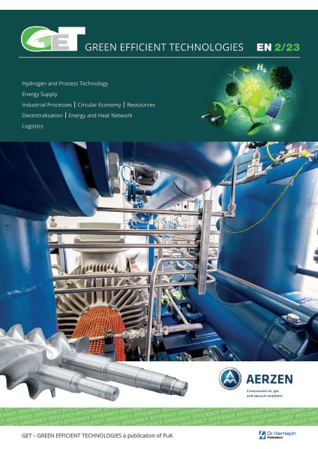
GET – GREEN EFFICIENT TECHNOLOGIES EN 2/23
“GET – GREEN EFFICIENT TECHNOLOGIES” is the new independent media platform for energy supply, efficiency improvement and alternative energy sources and storage. There is still a high potential to save energy in industry. Efficiency is not only important for the profitability of a company, it is also target-oriented and saves resources. The importance of efficiency, especially in energy production, the role played by hydrogen, industrial processes, resource and recycling management, how energy can be stored and much more can be found in the new GET. “GET – GREEN EFFICIENT TECHNOLOGIES” is a publication of the of PuK. The trade medium will be published in 2023 in German as a print and digital edition on 25 May and 7 November and in English only as a digital edition on 5 July and 29 November.
“GET – GREEN EFFICIENT TECHNOLOGIES” is the new independent media platform for energy supply, efficiency improvement and alternative energy sources and storage.
There is still a high potential to save energy in industry. Efficiency is not only important for the profitability of a company, it is also target-oriented and saves resources.
The importance of efficiency, especially in energy production, the role played by hydrogen, industrial processes, resource and recycling management, how energy can be stored and much more can be found in the new GET.
“GET – GREEN EFFICIENT TECHNOLOGIES” is a publication of the of PuK. The trade medium will be published in 2023 in German as a print and digital edition on 25 May and 7 November and in English only as a digital edition on 5 July and 29 November.

Create successful ePaper yourself
Turn your PDF publications into a flip-book with our unique Google optimized e-Paper software.
<strong>GRE<strong>EN</strong></strong> <strong>EFFICI<strong>EN</strong>T</strong> <strong>TECHNOLOGIES</strong><br />
<strong>EN</strong> 2/<strong>23</strong><br />
Hydrogen and Process Technology<br />
Energy Supply<br />
Industrial Processes Circular Economy Ressources<br />
Decentralisation<br />
Energy and Heat Network<br />
Logistics<br />
FICI<strong>EN</strong>CY EFFICI<strong>EN</strong>CY EFFICI<strong>EN</strong>CY EFFICI<strong>EN</strong>CY EFFICI<strong>EN</strong>CY EFFICI<strong>EN</strong>CY EFFICI<strong>EN</strong>CY EFFICI<strong>EN</strong>CY EFFICI<strong>EN</strong>CY EFFICI<strong>EN</strong>CY EFFICI<strong>EN</strong>CY EFFICIE<br />
CY EFFICI<strong>EN</strong>CY EFFICI<strong>EN</strong>CY EFFICI<strong>EN</strong>CY EFFICI<strong>EN</strong>CY EFFICI<strong>EN</strong>CY EFFICI<strong>EN</strong>CY EFFICI<strong>EN</strong>CY EFFICI<strong>EN</strong>CY EFFICI<strong>EN</strong>CY EFFICI<strong>EN</strong>CY EFFICI<strong>EN</strong>CY<br />
FICI<strong>EN</strong>CY EFFICI<strong>EN</strong>CY EFFICI<strong>EN</strong>CY EFFICI<strong>EN</strong>CY EFFICI<strong>EN</strong>CY EFFICI<strong>EN</strong>CY EFFICI<strong>EN</strong>CY EFFICI<strong>EN</strong>CY EFFICI<strong>EN</strong>CY EFFICI<strong>EN</strong>CY EFFICI<strong>EN</strong>CY EFFIC<br />
CY EFFICI<strong>EN</strong>CY EFFICI<strong>EN</strong>CY EFFICI<strong>EN</strong>CY EFFICI<strong>EN</strong>CY EFFICI<strong>EN</strong>CY EFFICI<strong>EN</strong>CY EFFICI<strong>EN</strong>CY EFFICI<strong>EN</strong>CY EFFICI<strong>EN</strong>CY EFFICI<strong>EN</strong>CY EFFICI<strong>EN</strong>CY<br />
FFICI<strong>EN</strong>CY EFFICI<strong>EN</strong>CY EFFICI<strong>EN</strong>CY EFFICI<strong>EN</strong>CY EFFICI<strong>EN</strong>CY EFFICI<strong>EN</strong>CY EFFICI<strong>EN</strong>CY EFFICI<strong>EN</strong>CY EFFICI<strong>EN</strong>CY EFFICI<strong>EN</strong>CY EFFICI<strong>EN</strong>CY EFFIC<br />
NCY EFFICI<strong>EN</strong>CY EFFICI<strong>EN</strong>CY EFFICI<strong>EN</strong>CY EFFICI<strong>EN</strong>CY EFFICI<strong>EN</strong>CY EFFICI<strong>EN</strong>CY EFFICI<strong>EN</strong>CY EFFICI<strong>EN</strong>CY EFFICI<strong>EN</strong>CY EFFICI<strong>EN</strong>CY EFFICI<strong>EN</strong>CY<br />
EFFICI<strong>EN</strong>CY EFFICI<strong>EN</strong>CY EFFICI<strong>EN</strong>CY EFFICI<strong>EN</strong>CY EFFICI<strong>EN</strong>CY EFFICI<strong>EN</strong>CY EFFICI<strong>EN</strong>CY EFFICI<strong>EN</strong>CY EFFICI<strong>EN</strong>CY EFFICI<strong>EN</strong>CY EFFICI<strong>EN</strong>CY EFFI<br />
<strong>EN</strong>CY EFFICI<strong>EN</strong>CY EFFICI<strong>EN</strong>CY EFFICI<strong>EN</strong>CY EFFICI<strong>EN</strong>CY EFFICI<strong>EN</strong>CY EFFICI<strong>EN</strong>CY EFFICI<strong>EN</strong>CY EFFICI<strong>EN</strong>CY EFFICI<strong>EN</strong>CY EFFICI<strong>EN</strong>CY EFFICI<strong>EN</strong>C<br />
EFFICI<strong>EN</strong>CY EFFICI<strong>EN</strong>CY EFFICI<strong>EN</strong>CY EFFICI<strong>EN</strong>CY EFFICI<strong>EN</strong>CY EFFICI<strong>EN</strong>CY EFFICI<strong>EN</strong>CY EFFICI<strong>EN</strong>CY EFFICI<strong>EN</strong>CY EFFICI<strong>EN</strong>CY EFFICI<strong>EN</strong>CY EFF<br />
I<strong>EN</strong>CY EFFICI<strong>EN</strong>CY EFFICI<strong>EN</strong>CY EFFICI<strong>EN</strong>CY EFFICI<strong>EN</strong>CY EFFICI<strong>EN</strong>CY EFFICI<strong>EN</strong>CY EFFICI<strong>EN</strong>CY EFFICI<strong>EN</strong>CY EFFICI<strong>EN</strong>CY EFFICI<strong>EN</strong>CY EFFICI<strong>EN</strong>C<br />
EFFICI<strong>EN</strong>CY EFFICI<strong>EN</strong>CY EFFICI<strong>EN</strong>CY EFFICI<strong>EN</strong>CY EFFICI<strong>EN</strong>CY EFFICI<strong>EN</strong>CY EFFICI<strong>EN</strong>CY EFFICI<strong>EN</strong>CY EFFICI<strong>EN</strong>CY EFFICI<strong>EN</strong>CY EFFICI<strong>EN</strong>CY EF<br />
CI<strong>EN</strong>CY EFFICI<strong>EN</strong>CY EFFICI<strong>EN</strong>CY EFFICI<strong>EN</strong>CY EFFICI<strong>EN</strong>CY EFFICI<strong>EN</strong>CY EFFICI<strong>EN</strong>CY EFFICI<strong>EN</strong>CY EFFICI<strong>EN</strong>CY EFFICI<strong>EN</strong>CY EFFICI<strong>EN</strong>CY EFFICI<strong>EN</strong><br />
Y EFFICI<strong>EN</strong>CY EFFICI<strong>EN</strong>CY EFFICI<strong>EN</strong>CY EFFICI<strong>EN</strong>CY EFFICI<strong>EN</strong>CY EFFICI<strong>EN</strong>CY EFFICI<strong>EN</strong>CY EFFICI<strong>EN</strong>CY EFFICI<strong>EN</strong>CY EFFICI<strong>EN</strong>CY EFFICI<strong>EN</strong>CY E<br />
ICI<strong>EN</strong>CY EFFICI<strong>EN</strong>CY EFFICI<strong>EN</strong>CY EFFICI<strong>EN</strong>CY EFFICI<strong>EN</strong>CY EFFICI<strong>EN</strong>CY EFFICI<strong>EN</strong>CY EFFICI<strong>EN</strong>CY EFFICI<strong>EN</strong>CY EFFICI<strong>EN</strong>CY EFFICI<strong>EN</strong>CY EFFICIE<br />
CY EFFICI<strong>EN</strong>CY EFFICI<strong>EN</strong>CY EFFICI<strong>EN</strong>CY EFFICI<strong>EN</strong>CY EFFICI<strong>EN</strong>CY EFFICI<strong>EN</strong>CY EFFICI<strong>EN</strong>CY EFFICI<strong>EN</strong>CY EFFICI<strong>EN</strong>CY EFFICI<strong>EN</strong>CY EFFICI<strong>EN</strong>CY<br />
FICI<strong>EN</strong>CY EFFICI<strong>EN</strong>CY EFFICI<strong>EN</strong>CY EFFICI<strong>EN</strong>CY EFFICI<strong>EN</strong>CY EFFICI<strong>EN</strong>CY EFFICI<strong>EN</strong>CY EFFICI<strong>EN</strong>CY EFFICI<strong>EN</strong>CY EFFICI<strong>EN</strong>CY EFFICI<strong>EN</strong>CY EFFICIE<br />
CY EFFICI<strong>EN</strong>CY EFFICI<strong>EN</strong>CY EFFICI<strong>EN</strong>CY EFFICI<strong>EN</strong>CY EFFICI<strong>EN</strong>CY EFFICI<strong>EN</strong>CY EFFICI<strong>EN</strong>CY EFFICI<strong>EN</strong>CY EFFICI<strong>EN</strong>CY EFFICI<strong>EN</strong>CY EFFICI<strong>EN</strong>CY<br />
Y EFFICI<strong>EN</strong>CY EFFICI<strong>EN</strong>CY EFFICI<strong>EN</strong>CY EFFICI<strong>EN</strong>CY EFFICI<strong>EN</strong>CY EFFICI<strong>EN</strong>CY EFFICI<strong>EN</strong>CY EFFICI<strong>EN</strong>CY EFFICI<strong>EN</strong>CY EFFICI<strong>EN</strong>CY EFFIC<br />
I<strong>EN</strong>CY EFFICI<strong>EN</strong>CY EFFICI<strong>EN</strong>CY EFFICI<strong>EN</strong>CY EFFICI<strong>EN</strong>CY EFFICI<strong>EN</strong>CY EFFICI<strong>EN</strong>CY EFFICI<strong>EN</strong>CY EFFICI<strong>EN</strong>CY EFFICI<strong>EN</strong>CY<br />
FICI<strong>EN</strong>CY EFFICI<strong>EN</strong>CY EFFICI<strong>EN</strong>CY EFFICI<strong>EN</strong>CY EFFICI<strong>EN</strong>CY EFFICI<strong>EN</strong>CY EFFICI<strong>EN</strong>CY EFFICI<strong>EN</strong>CY EFFIC<br />
Y EFFICI<strong>EN</strong>CY EFFICI<strong>EN</strong>CY EFFICI<strong>EN</strong>CY EFFICI<strong>EN</strong>CY EFFICI<strong>EN</strong>CY EFFICI<strong>EN</strong>CY EFFICI<strong>EN</strong>C<br />
I<strong>EN</strong>CY EFFICI<strong>EN</strong>CY EFFICI<strong>EN</strong>CY EFFICI<strong>EN</strong>CY EFFICI<strong>EN</strong>CY EFFICI<strong>EN</strong>CY EFFI<br />
FFICI<strong>EN</strong>CY EFFICI<strong>EN</strong>CY EFFICI<strong>EN</strong>CY EFFICI<strong>EN</strong>CY EFFICI<strong>EN</strong>C<br />
CY EFFICI<strong>EN</strong>CY EFFICI<strong>EN</strong>CY EFFICI<strong>EN</strong>CY EFF<br />
<strong>GET</strong> <strong>–</strong> <strong>GRE<strong>EN</strong></strong> <strong>EFFICI<strong>EN</strong>T</strong> <strong>TECHNOLOGIES</strong> a publication of PuK
HANNOVER MESSE 2024<br />
<strong>EN</strong>ERGIZING A<br />
SUSTAINABLE<br />
INDUSTRY<br />
Products and solutions at #HM24<br />
22 <strong>–</strong> 26 April 2024 Hannover, Germany<br />
hannovermesse.com<br />
WORLD. LEADING. INDUSTRYSHOW.
Editorial<br />
European hubris<br />
“The world should recover from the German character” - this well-known saying by the poet Emanuel Geibel from 1861<br />
was originally meant in a completely different way. At present, however, it aptly describes the typical German behaviour<br />
of the missionary desire to teach others coupled with a consistent overestimation of one’s own possibilities and an ideologically<br />
limited view of things. Germany has (fortunately?) had little influence in world politics for decades - but the EU<br />
has now adopted this moralising behaviour in its dealings with the rest of the world.<br />
We are the good guys<br />
This is made clear in an EU press release from 5 October 20<strong>23</strong> on the agreement reached on the handling of F-gases,<br />
such as those used in air conditioning systems, refrigeration machines and fire protection systems. The European<br />
Parliament and the EU member states have reached a provisional agreement to tighten the regulations on the use of<br />
fluorinated gases and ozone-depleting substances. Maroš Šefčovič, Executive Vice-President for European Green deal,<br />
Interinstitutional Relations and Foresight, commented as follows on 5 October 20<strong>23</strong>: „Thanks to the agreement found<br />
today to phase out the F-gases and ozone-depleting substances, we will prevent 32,000 tonnes of ozone-depleting emissions<br />
and save the equivalent of almost 500 million tonnes of CO 2 by 2050. This is excellent news for Europe and for the<br />
world. With F-gases used for air conditioning and refrigeration and demand in this area projected to grow, it is essential<br />
that we make sure these technologies do not exacerbate global warming and that climate-friendly alternatives are<br />
incentivised.“<br />
So far - so good. The Commission elegantly ignored the fact that European refrigeration system manufacturers and<br />
maintenance companies see massive problems and costs looming for themselves and their customers. The following<br />
sentence in the announcement is revealing of the Commission's own mission and assessment of its own importance in<br />
the world: „The Regulation provides incentives to use climate-friendly alternatives, further stimulating the global market<br />
and helping other countries to make the transition as well.“<br />
The other countries will certainly be happy about this. And of course immediately implement what the EU wants.<br />
To be continued<br />
However, this was possibly only the overture for the much larger all-round attack on PFAS restrictions. The ban discussion<br />
initiated by five European environment ministries would have much more serious consequences for European<br />
companies. Global competitors, on the other hand (and probably the environment as a whole), should actually be<br />
pleased about the opportunities for growth if they are allowed to continue using the better plastics.<br />
Showdown in Helsinki<br />
ECHA staff in Helsinki should therefore keep a cool head as they are currently discussing a recommendation to restrict<br />
or even ban PFAS in the EU. Our lead article on the following pages looks at important aspects of these eternal plastics.<br />
Have fun reading.<br />
Ottmar Holz<br />
Editor<br />
<strong>GRE<strong>EN</strong></strong> <strong>EFFICI<strong>EN</strong>T</strong> <strong>TECHNOLOGIES</strong> 20<strong>23</strong><br />
3
<strong>GRE<strong>EN</strong></strong> <strong>EFFICI<strong>EN</strong>T</strong> <strong>TECHNOLOGIES</strong><br />
Contents<br />
Cover<br />
Focus on security of supply:<br />
Screw compressors from AERZ<strong>EN</strong> feed biomethane<br />
into the gas network<br />
Security of supply is what counts in the energy industry. For the systems<br />
in use, this results in high demands on availability and reliability.<br />
Whereas smaller power plants, solar farms or wind farms can be<br />
shut down in a relatively simple manner or completely taken off the<br />
network, this is much more difficult with biogas plants. Biological processes<br />
cannot simply be stopped, which is why maximum reliability<br />
and redundancy are required for the technical equipment. EWE NETZ<br />
GmbH uses AERZ<strong>EN</strong> screw compressors to feed biomethane into the<br />
natural gas network for the pre-compression of the biomethane.<br />
Contents<br />
Editorial<br />
European hubris 3<br />
Cover story<br />
Focus on security of supply 6<br />
Leading article<br />
An end to eternity 9<br />
Construction technology<br />
“A universal PFAS ban is not progress in every case” 17<br />
Production organisation<br />
Material flow under clean conditions 20<br />
Energy infrastructure<br />
Strengthening charging infrastructures for electric vehicles<br />
with energy storage systems <strong>23</strong><br />
Cosy warmth from old tunnels 27<br />
Energy effiiency<br />
Reducing air pressure in compressed air systems 30<br />
Hydrogen economy<br />
Dimethyl ether: new transport medium for efficient hydrogen transport 32<br />
The potential of plastic pipes in battery cell production 34<br />
Highly specific safety concepts for hydrogen infrastructures 36<br />
Companies <strong>–</strong> Innovations <strong>–</strong> Products 38<br />
Index of Advertisers 39<br />
Brand name register 40<br />
Impressum<br />
Publisher<br />
Dr. Harnisch Verlags GmbH in cooperation with<br />
Prof. (ret.) Dr.-Ing. Eberhard Schlücker, advisor<br />
on hydrogen and energy issues<br />
©<br />
20<strong>23</strong>, Dr. Harnisch Verlags GmbH<br />
Responsible for content<br />
Ottmar Holz<br />
Silke Watkins<br />
Publishing company and reader service<br />
Dr. Harnisch Verlags GmbH<br />
Eschenstr. 25<br />
90441 Nuremberg, Germany<br />
Tel 0911 2018-0<br />
Fax 0911 2018-100<br />
E-Mail get@harnisch.com<br />
www.harnisch.com<br />
Errors excepted<br />
Reprinting and photomechanical reproduction,even<br />
in extract form, is only possible with<br />
the written consent of the publishers<br />
Editors<br />
Ottmar Holz<br />
Silke Watkins<br />
Advertisements/Brand name register<br />
Silke Watkins/Matti Schneider<br />
Technical Director<br />
Armin König<br />
ISSN 2752-2040<br />
4<br />
<strong>GRE<strong>EN</strong></strong> <strong>EFFICI<strong>EN</strong>T</strong> <strong>TECHNOLOGIES</strong> 20<strong>23</strong>
Driving the world<br />
The right drive for<br />
your production<br />
Our Unser contribution Beitrag zur to energie-effizienten energy-efficient battery Batteriezellproduktion<br />
cell production<br />
The Der entire gesamte battery Prozess cell production der Batteriezellproduktion process must be muss sustainable, nachhaltig, flexible flexibel and und intelligent.<br />
Innovative sein. Innovative and modern und moderne automation Automatisierung plays an important leistet dabei role. We einen deliver enormen hardware Beitrag. and Wir liefern<br />
software Ihnen Lösungen solutions aus that Hard- fit perfectly und Software, together. die Our perfekt efficient aufeinander drive and abgestimmt automation sind. technology Unsere<br />
supports effiziente you Antriebs- throughout und Automatisierungstechnik the entire battery production unterstützt and assembly Sie entlang process des as gesamten well as in<br />
intralogistics Batterieproduktions- and the necessary und Montageprozesses storage processes. sowie bei der Intralogistik und den notwendigen<br />
Lagerprozessen.<br />
www.sew-eurodrive.de/battery-cell-production<br />
www.sew-eurodrive.de/movitrans
Cover story<br />
Focus on security of supply<br />
Screw compressors from AERZ<strong>EN</strong> feed biomethane<br />
into the gas network<br />
Sebastian Meißler<br />
Security of supply is what counts in<br />
the energy industry. For the systems<br />
in use, this results in high demands<br />
on availability and reliability.<br />
Whereas smaller power plants, solar<br />
farms or wind farms can be shut<br />
down in a relatively simple manner<br />
or completely taken off the network,<br />
this is much more difficult with biogas<br />
plants. Biological processes cannot<br />
simply be stopped, which is why<br />
maximum reliability and redundancy<br />
are required for the technical<br />
equipment. EWE NETZ GmbH uses<br />
AERZ<strong>EN</strong> screw compressors to feed<br />
biomethane into the natural gas<br />
network for the pre-compression of<br />
the biomethane.<br />
with the direct generation of electricity<br />
from biogas on site in a blocktype<br />
thermal power station, however,<br />
the producer must process the biogas<br />
into biomethane before it can be<br />
fed into the natural gas network. The<br />
local natural gas network operator is<br />
responsible for the feed-in with special<br />
equipment. One functional area<br />
here is pre-compression, for which<br />
EWE NETZ GmbH uses screw compressors<br />
from AERZ<strong>EN</strong>. This process<br />
is divided into two pressure stages.<br />
In the first pressure stage packages<br />
from AERZ<strong>EN</strong> are used, and for the<br />
high pressure range reciprocating<br />
compressors from Neumann and<br />
Esser are used.<br />
Cloppenburg reach the EWE NETZ<br />
GmbH feed-in station every hour at<br />
a transfer pressure of around 100<br />
millibar. “The number of agricultural<br />
businesses is high in this region,”<br />
says Christoph Benten, who is<br />
responsible for biogas feed-in plants<br />
at EWE NETZ. The energy supplier,<br />
which has its headquarters in Oldenburg<br />
does not operate the biogas<br />
plant or the processing plant in the<br />
Processing biogas into biomethane<br />
and feeding it into the natural gas<br />
network: this represents an effective<br />
way of storing the regeneratively<br />
produced energy source. In contrast<br />
Ensuring gas quality<br />
As much as 700 standard cubic<br />
metres of biomethane from a biogas<br />
treatment plant in the district of<br />
Fig. 1: The feed station is installed in a<br />
mobile and space-saving way in a concrete<br />
container directly next to the gas treatment<br />
plant <br />
(All images: AERZ<strong>EN</strong>)<br />
6<br />
<strong>GRE<strong>EN</strong></strong> <strong>EFFICI<strong>EN</strong>T</strong> <strong>TECHNOLOGIES</strong> 20<strong>23</strong>
Cover story<br />
district of Cloppenburg. Rather, the<br />
company provides the gas network<br />
and the infrastructure for feed-in. In<br />
this constellation, EWE NETZ GmbH<br />
is responsible for the biomethane<br />
qualities handed over, the necessary<br />
pressure adjustment and the<br />
adjustment of the calorific value for<br />
the safe feed-in of biomethane into<br />
the natural gas network. The guidelines<br />
of the DVGW (German Technical<br />
and Scientific Association for Gas<br />
and Water) must be observed. The<br />
rules and regulations specify, among<br />
other things, the methane content<br />
transferred, the limit values for carbon<br />
dioxide and hydrogen sulphide,<br />
and the water dew point. If the transferred<br />
biomethane remains within<br />
the limits, the pressure is increased<br />
from about 100 millibar to five bar by<br />
means of screw compressors from<br />
AERZ<strong>EN</strong>. The local network itself is<br />
operated at a pressure of between<br />
0.8 and 0.9 bar and supplies the<br />
connected companies and households<br />
with natural gas or injected<br />
bio methane. Christoph Benten: “The<br />
German legislative authority stipulates<br />
that when we feed biomethane<br />
into the natural gas network, we must<br />
achieve a technical availability of the<br />
feed-in plant of at least 96 percent.”<br />
For this reason, EWE NETZ GmbH<br />
maintains a redundant operation<br />
of two identical VMX 110 packages<br />
from AERZ<strong>EN</strong>. Each of these delivers<br />
a capacity of 700 standard cubic<br />
metres per hour. “If one machine<br />
malfunctions, the second machine<br />
automatically takes over.”<br />
Fig. 2: Screw compressors from AERZ<strong>EN</strong> compress the biomethane for feeding into the local<br />
gas network<br />
as the DVGW regulations for use in<br />
Germany.<br />
The screw compressors are<br />
installed in the feed-in plant in the<br />
district of Cloppenburg in a compact<br />
concrete building, which is located<br />
right next to the biogas processing<br />
plant of the biogas plants. The unit<br />
is designed as a ready-to-connect<br />
system that can be put into operation<br />
quickly. “The advantages of the<br />
compact modular design are the<br />
quick and uncomplicated assembling<br />
to another location and the<br />
possibility of being able to dismantle<br />
the system again relatively easily<br />
for moving to another location,”<br />
says Christoph Benten. AERZ<strong>EN</strong> has<br />
delivered the two screw compressors<br />
as a complete system. An important<br />
project participant: Elektrotechnik<br />
GmbH Schaumburg (ELOG). ELOG<br />
was responsible for engineering support<br />
in the area of EMSR technology,<br />
switchgear construction up to commissioning<br />
and the integration of the<br />
system into a higher-level control and<br />
management level. EWE NETZ GmbH<br />
specifies basic engineering and the<br />
definition of interfaces for signal<br />
exchange with the control system for<br />
its sites. Benten: “What matters to us<br />
in this turnkey plant construction is<br />
that the technology used operates<br />
with a high degree of availability and<br />
with few disruptions.”<br />
Approved system solution<br />
Compression of biomethane, biogas<br />
and other mixed hydrocarbon gases:<br />
This is exactly what the oil-lubricated<br />
direct-drive VMX screw compressor<br />
packages are designed for. In five<br />
sizes, the series covers volume flows<br />
of up to 2.500 standard cubic metres<br />
per hour in continuous operation and<br />
delivers a positive pressure of up to<br />
16 bar. For use in the vicinity of biogas<br />
plants, the packages are certified<br />
in accordance with the ATEX directive<br />
2014/34/EU and the machinery directive.<br />
The VMX series meets the latest<br />
safety standards of <strong>EN</strong> 1012-3 as well<br />
Fig. 3: AERZ<strong>EN</strong> delivered a complete ready-to-install solution for EWE, including piping and<br />
connection to the control level<br />
<strong>GRE<strong>EN</strong></strong> <strong>EFFICI<strong>EN</strong>T</strong> <strong>TECHNOLOGIES</strong> 20<strong>23</strong> 7
Cover story<br />
Fig. 4: The VMX screw compressors are rated for maximum availability. What counts, after all, is the security of supply for the feed-in<br />
Different gas qualities<br />
EWE NETZ GmbH uses official calibration<br />
gas analyses to determine<br />
the quality of the biomethane transferred,<br />
and thus verifies the required<br />
limit values in a shutdown matrix. If<br />
the transferred biomethane does not<br />
reach the required transfer parameters,<br />
the feed into the natural gas<br />
network is stopped until the limit values<br />
are met again. As soon as biomethane<br />
is fed into the natural gas<br />
network, EWE NETZ GmbH must<br />
compare the calorific value of the<br />
bio methane transferred with the current<br />
calorific value within the natural<br />
gas network to be fed into and adjust<br />
the bio methane accordingly. There<br />
are two different types of adaptation<br />
(conditioning), which are dependent<br />
on the local natural gas network.<br />
There are currently two calorific value<br />
Fig. 5: With the compression of biomethane,<br />
the renewably produced fuel can<br />
be efficiently fed into existing gas networks<br />
bands within the natural gas networks<br />
in Germany. These are the<br />
L-gas network (low calorific range)<br />
and the H-gas network (high calorific<br />
range). When fed into an L-gas network,<br />
air must be added to the biomethane<br />
to reduce its calorific value.<br />
When feeding into an H-gas network,<br />
the calorific value must again be<br />
increased by adding liquefied petroleum<br />
gas (LPG). The exact dosage of<br />
air or LPG is automatically adjusted<br />
via gas mixers. Projects are currently<br />
underway in Germany and at EWE<br />
NETZ GmbH to convert from L-gas<br />
networks to H-gas networks because<br />
the availability of L-gas is limited.<br />
A further distinction in terms of<br />
feed-in is to be found in the network<br />
into which the gas is fed. The local<br />
distribution network works with a<br />
maximum of 1 bar, the high pressure<br />
network with up to 70 bar. As long as<br />
intake capacities are available within<br />
the local distribution network, the<br />
AERZ<strong>EN</strong> screw compressors feed in.<br />
If a bottleneck occurs, the feed into<br />
the high-pressure network is automatically<br />
activated. Then reciprocating<br />
compressors from Neumann<br />
and Esser take over. The AERZ<strong>EN</strong><br />
screw compressors remain in operation<br />
and generate the raised intake<br />
pressure for the high-pressure compressors.<br />
This design means that the<br />
reciprocating compressors are only<br />
used for energy reasons when the<br />
local network is no longer absorbing<br />
anything and 70 bar feed pressure is<br />
required.<br />
Biomethane: Renewable energy<br />
in the gas network<br />
The injection of biomethane into<br />
the existing natural gas network<br />
improves the storage possibilities of<br />
biogas and the use of the generated<br />
energy independent of the location<br />
of the biogas plant. Moreover, a time-<br />
related decoupling of generation and<br />
use is possible. With a total length of<br />
530,000 kilometres, the infrastructure<br />
of the natural gas network with<br />
the associated caverns is considered<br />
well developed in Germany. Complete<br />
system solutions for the compression<br />
and injection of gas make<br />
it easier for network operators to<br />
develop new locations.<br />
The Author:<br />
Sebastian Meißler, Marketing<br />
Aerzener Maschinenfabrik GmbH<br />
Reherweg 28<br />
31855 Aerzen, Germany<br />
Tel + 49 5154 81<br />
info@aerzen.com<br />
www.aerzen.com<br />
8<br />
<strong>GRE<strong>EN</strong></strong> <strong>EFFICI<strong>EN</strong>T</strong> <strong>TECHNOLOGIES</strong> 20<strong>23</strong>
Photo: Adobe Stock/Octavian<br />
Leading article<br />
An end to eternity<br />
Ottmar Holz<br />
On 22 March 20<strong>23</strong>, the European<br />
Chemicals Agency (ECHA) published<br />
a proposal for a ban on the manufacture,<br />
use and placing on the<br />
market, including the import of perfluoroalkyl<br />
substances (PFAS). Should<br />
these industrial chemicals with their<br />
special technical properties actually<br />
be banned by the EU Commission<br />
in 2025, this would probably have<br />
far-reaching consequences for many<br />
areas of life - from fried eggs to the<br />
politically mandated energy transition.<br />
PFAS, perfluorinated and polyfluorinated<br />
alkyl substances, are<br />
widely used in almost all areas of life,<br />
from coated pans and outdoor jackets<br />
to glossy business cards. Due to<br />
their distinctive properties such as<br />
high chemical and thermal stability,<br />
non-stick and strong water and oil<br />
repellency, they are widely known<br />
under brand names such as Teflon<br />
and GoreTex.<br />
However, the advantages of these<br />
materials come with disadvantages:<br />
PFAS do not degrade in the environment<br />
and do so for centuries. They<br />
are also highly mobile and can now<br />
be detected worldwide in ground and<br />
surface water, air and soil as well as in<br />
the human bloodstream and in many<br />
living organisms.<br />
They are strongly<br />
suspected of causing<br />
cancer, infertility and<br />
other serious diseases. The toxicity<br />
of some substances in this class of<br />
materials has already been proven.<br />
Despite the long-known problems,<br />
significant steps have only<br />
recently been taken to curb the<br />
spread of PFAS: In November 2022,<br />
the US state of California filed extensive<br />
lawsuits against PFAS-producing<br />
companies such as 3M and Dupont.<br />
Just one month later, 3M became<br />
the first major chemical company to<br />
announce that it would completely<br />
cease production of PFAS substances<br />
by the end of 2025.<br />
PFAS are also ubiquitous in<br />
Europe. A „map of eternal pollution“,<br />
which was created as part of the „Forever<br />
Pollution Project“, illustrates the<br />
extent of the contamination. Journalists<br />
from 18 newspapers and media<br />
houses, including renowned names<br />
such as Le Monde (France), NDR,<br />
WDR, Süddeutsche Zeitung (Germany)<br />
and The Guardian (UK), contributed<br />
to the project.<br />
Against this backdrop, a comprehensive<br />
EU-wide ban on the use<br />
and production of PFAS as a class of<br />
substances was initiated by<br />
Denmark, Germany, the Netherlands,<br />
Norway and Sweden. In<br />
February 20<strong>23</strong>, the European Chemicals<br />
Agency (ECHA) published the<br />
proposal and is currently reviewing<br />
it before issuing a recommendation<br />
to the European Commission. The<br />
main counter-arguments centre on<br />
the lack of equivalent alternatives for<br />
PFAS in applications considered critical<br />
to society.<br />
From 22 March to 25 September,<br />
the ECHA gave affected companies<br />
and institutions the opportunity<br />
to comment on the proposed restriction<br />
in a consultation process.<br />
According to the ECHA, more than<br />
4,400 organisations, companies and<br />
private individuals submitted more<br />
than 5,600 comments on the topic by<br />
the deadline.<br />
What are PFAS<br />
A PFAS list published by the OECD<br />
in 2018 includes more than 4,700<br />
entries. In addition, there are<br />
unwanted synthesis by-products<br />
Fig. 1: Perfluorooctane sulphonate (PFOS) is one of the most common and most discussed PFAS compounds. Eight fluorinated carbon atoms<br />
(green/black) form the basic structure to which a sulphonic acid group (SO 3 H) is attached. <br />
Graphic: Eurowater<br />
<strong>GRE<strong>EN</strong></strong> <strong>EFFICI<strong>EN</strong>T</strong> <strong>TECHNOLOGIES</strong> 20<strong>23</strong> 9
Leading article<br />
and impurities as well as transformation<br />
products that can arise in<br />
the environment both abiotically<br />
and through biodegradation. Potential<br />
degradation products of many<br />
PFAS belong to the extremely persistent<br />
perfluorinated carbon and<br />
sulfonic acids. They can be found<br />
in many things in our everyday<br />
lives: Whether in dental floss, baking<br />
paper, outdoor clothing or extinguishing<br />
and plant protection agents<br />
- PFAS ensure that products everywhere<br />
are water, grease and dirt<br />
repellent. But PFAS are not only useful<br />
as a coating - they can also be<br />
used to produce extremely resistant<br />
plastic bodies and films. These are<br />
used in electrolysers and fuel cells,<br />
for example. What characterises<br />
PFAS for these applications poses a<br />
problem in terms of the disposal of<br />
the chemicals: They are extremely<br />
thermally and chemically stable and<br />
cannot be degraded by light, water<br />
or bacteria.<br />
More than 10,000 different chemicals<br />
are currently the focus of the<br />
restriction process. A generally valid<br />
definition is difficult due to the large<br />
number, one of the possible distinguishing<br />
features is the length of the<br />
carbon chain. Short-chain PFAS with<br />
less than 10 to 13 carbon atoms are<br />
particularly problematic as they dissolve<br />
quite well in water. PFAS can<br />
now be detected in soil, water and<br />
groundwater throughout Europe.<br />
They also end up in our food, and<br />
PFAS can even be found in breast<br />
milk. There are many good reasons<br />
for a ban: Many studies show that<br />
the sometimes toxic chemicals accumulate<br />
in the human body. This has<br />
considerable health effects, ranging<br />
from damage to organs to cancer or<br />
developmental disorders.<br />
Due to their chemical stabili ty,<br />
the elimination of so-called perpetual<br />
chemicals has so far been virtually<br />
impossible with reasonable<br />
effort. Filtering with activated carbon,<br />
for example, binds PFAS but<br />
does not eliminate them, meaning<br />
that the residues have to be disposed<br />
of or stored as hazardous<br />
waste. Activated carbon is also more<br />
suitable for removing long-chain<br />
PFAS.<br />
Who needs these plastics?<br />
Given the ubiquity of these plastics,<br />
it is not possible to even begin to<br />
describe all possible areas of application<br />
within the scope of one article.<br />
However, some sectors in key areas<br />
of industry and the energy transition<br />
would be particularly affected by a<br />
ban. These include electrolyser and<br />
fuel cell manufacturers as well as suppliers<br />
of sealing materials and pump<br />
and compressor manufacturers.<br />
In the current debate, those in<br />
favour of the ban like to argue that<br />
it is necessary to intensify the search<br />
for alternative materials. However,<br />
this could prove difficult in some<br />
areas - because the industry has been<br />
researching for a long time without<br />
success for cheaper and yet equally<br />
high-performance substitutes for<br />
the sometimes extremely expensive<br />
special coatings and sealing materials.<br />
One reason for the long-running,<br />
intensive research into replacements<br />
is the extreme wear resistance of<br />
PFAS. It is based on a very special<br />
physical effect, the tribological film.<br />
Tribology is the science of friction,<br />
lubrication and wear of mechanical<br />
components that move relative to<br />
each other. (You can read about the<br />
special role PFAS play here in the following<br />
article from page 17)<br />
Energy transition on the brink<br />
Energy generation from fossil fuels<br />
must come to an end - most countries<br />
in the world and scientists agree<br />
on this. But how can we fuel all the<br />
blast furnaces, cement works, power<br />
stations and buildings in the world if<br />
natural gas, oil and coal are no longer<br />
an energy source? Hydrogen is the<br />
obvious energy source here. After<br />
all, chemically speaking, only water<br />
is produced during combustion. But<br />
this only applies to hydrogen produced<br />
from water by electrolysis. And<br />
here, too, there is currently no alternative<br />
application for the PFAS substance<br />
group.<br />
Hydrogen fuel cells and electrolysers<br />
play a decisive role in the<br />
urgently needed energy transition.<br />
The central components of both units<br />
are semi-permeable films coated<br />
with special catalyser metals. They<br />
currently consist of perfluorinated<br />
sulphonic acids (PFSA) - a specific<br />
material of the PFAS material class<br />
and are currently used, for example,<br />
in membrane electrode assemblies<br />
(MEAs) of fuel cells due to their<br />
high proton conductivity and chemical<br />
stability. The company ionysis has<br />
set itself the goal of minimising and<br />
completely replacing the use of PFSA<br />
in MEAs.<br />
Also works without fluorine<br />
This start-up from Freiburg, a spinoff<br />
from the „Electrochemical Energy<br />
Systems“ department at Hahn-<br />
Schickard and the University of<br />
Freiburg, is developing more environmentally<br />
friendly and fluorine-free<br />
MEAs without compromising on performance<br />
or costs. In addition, the<br />
focus is on demonstrating technical<br />
feasibility on a relevant scale.<br />
Recently, the team was able to provide<br />
the first successful proof of performance<br />
in heavy-duty full format<br />
and in the short stack. „Together with<br />
national and international partners,<br />
we are pursuing the goal of developing<br />
innovative MEAs for fuel cells,<br />
bringing them to market maturity and<br />
thus making a contribution to a truly<br />
sustainable 'green' hydrogen economy.<br />
Achieving state-of-the-art performance<br />
and validation in the short<br />
stack represents an important milestone<br />
in the early phase of our company,“<br />
says Lisa Langer, co-founder<br />
and CFO of ionysis.<br />
So everything is fine - right?<br />
Not quite as optimistic are practically<br />
all manufacturers of the film material<br />
- such as Chemours, Evonik, Dongyue<br />
and Gore - as well as electrolyser<br />
manufacturers and seal producers.<br />
The editorial team interviewed<br />
H-Tec Systems, a well-known German<br />
electrolyser manufacturer, on behalf<br />
of the company.<br />
<strong>GET</strong>: Do you see a risk to the energy<br />
transition being promoted by the<br />
German government in the event<br />
of a possible ban on PFAS due to<br />
the lack of equivalent plastics for<br />
10<br />
<strong>GRE<strong>EN</strong></strong> <strong>EFFICI<strong>EN</strong>T</strong> <strong>TECHNOLOGIES</strong> 20<strong>23</strong>
Leading article<br />
the production of membranes or<br />
stack seals for electrolysers and<br />
fuel cells?<br />
<strong>GET</strong>: Does the ban apply worldwide?<br />
Are there similar endeavours<br />
in other countries?<br />
electric drives), the pharmaceutical<br />
and food industries, as well as the<br />
chip and computer industry<br />
H-Tec Systems: A ban on PFAS would<br />
be tantamount to a ban on electrolysis<br />
of all kinds, as there is currently<br />
no economic and technical substitute<br />
with comparable performance. This<br />
would greatly slow down the development<br />
of the hydrogen economy in the<br />
EU and Europe would fall far behind<br />
the USA and China. The transition to<br />
renewable energy and the European<br />
Green Deal would be jeopardised.<br />
As part of the Green Deal, the<br />
EU announced the Circular Economy<br />
Action Plan (CEAP), which includes<br />
measures for electronic and ICT<br />
waste. A recycling regulation for electrolysis<br />
membranes with a high recycling<br />
value could be a viable option.<br />
<strong>GET</strong>: ECHA ran a consultation procedure<br />
until 21 September in which<br />
citizens, companies and other<br />
organisations can comment on this<br />
proposal. Have you submitted your<br />
concerns to the ECHA?<br />
H-Tec Systems: H-TEC SYSTEMS is taking<br />
part in the ECHA consultation. We<br />
are in close dialogue with our parent<br />
company MAN Energy Solutions and<br />
the VDMA and continue to participate<br />
in a working group of the National<br />
Hydrogen Council on this topic.<br />
Gasket manufacturers and their<br />
customers are also experiencing a<br />
mixture of uncertainty and fear of<br />
disadvantages when trading their<br />
products on the global market. The<br />
gasket specialist C. Otto Gehrckens<br />
GmbH & Co. KG (COG) organised an<br />
online discussion with its customers<br />
over the course of the year and<br />
answered a large number of questions<br />
from users from a wide range<br />
of industries. The <strong>GET</strong> editorial<br />
team also received some interesting<br />
answers.<br />
<strong>GET</strong>: Will the ban also affect alternatives<br />
such as fluororubber (FKM)<br />
or perfluororubber (FFKM)?<br />
COG: A general ban would affect all<br />
fluorine-containing qualities such as<br />
FKM, FFKM, FEPM, PTFE or FVMQ.<br />
COG: The PFAS restriction procedure<br />
under discussion is a purely<br />
European procedure. However, similar<br />
PFAS restriction endeavours are<br />
also underway in other countries,<br />
e.g. USA, China, Japan, etc. As far as<br />
we are aware, however, the issue is<br />
being dealt with in a more differentiated<br />
way here and no attempt is<br />
being made to categorically eliminate<br />
PFAS. The perspective on the scope of<br />
PFAS substances is different here. In<br />
Germany, the aim is to achieve a general<br />
ban on the entire PFAS group of<br />
around 10,000 different substances.<br />
In other countries, e.g. the USA or<br />
Japan, only certain PFAS substances<br />
that are proven to be toxic or otherwise<br />
harmful to the environment are<br />
considered in the banning process.<br />
<strong>GET</strong>: What happens after the ban<br />
or restriction of PFAS in gaskets?<br />
According to you, there is no alternative<br />
to the material.<br />
COG: There is indeed no alternative to<br />
fluoropolymers in some applications.<br />
We are not yet in a position to say<br />
whether and which alternatives will<br />
be developed here. In other applications,<br />
it is possible<br />
to work with<br />
alternatives, but<br />
they do not offer<br />
anywhere<br />
near<br />
the same level<br />
of performance.<br />
This<br />
inevitably<br />
leads to major<br />
technical<br />
setbacks<br />
in many<br />
areas.<br />
<strong>GET</strong>: Are alternatives currently<br />
being researched?<br />
COG: As fluoro rubbers, especially<br />
FFKM materials, are sometimes very<br />
expensive, research into alternative<br />
materials has been going on for many<br />
years. To date, no substitutes with<br />
comparable performance have been<br />
found. This includes applications for<br />
the energy transition (hydrogen or<br />
<strong>GET</strong>: Can anything be said about<br />
cost development?<br />
COG: As the substitute materials, if<br />
available at all, generally have a significantly<br />
poorer performance, the<br />
costs will rise accordingly due to<br />
shorter maintenance intervals or<br />
increased failures. These prices will<br />
inevitably be passed on to the (end)<br />
consumer.<br />
<strong>GET</strong>: There is talk in many places<br />
of alternatives to replace the<br />
PFAS- affected seals. Why are these<br />
alternatives not already in use?<br />
„An indiscriminate ban on<br />
PFAS would be a serious burden<br />
for the market ramp-up<br />
of fuel cells and many other<br />
transformation technologies.“<br />
Gerd Krieger, Managing Director VDMA<br />
e. V. Fuel Cell Working Group<br />
COG: The fact is that the alternatives<br />
currently available do not cover<br />
the same performance spectrum as<br />
fluoroelastomers. It is not only the<br />
excellent chemical resistance with<br />
simultaneous temperature resistance<br />
up to over 300 °C (with an FFKM)<br />
that makes a good FKM or FFKM sealing<br />
material, but also, in combination<br />
with the previous parameters,<br />
the recovery behaviour, the elastic<br />
behaviour over time, etc., that characterise<br />
a high-quality material. It is<br />
usually the case that the frequently<br />
mentioned<br />
extreme<br />
show<br />
substitutes<br />
weaknesses<br />
in one,<br />
often<br />
several<br />
areas. For example,<br />
in some<br />
areas<br />
chemical<br />
where<br />
resistance<br />
is required,<br />
an HNBR compound<br />
can be used instead of an FKM<br />
material. However, this is not the case<br />
if the elastomer seal is also required<br />
to seal at higher temperatures. Or if,<br />
for example in cleaning and sterilisation<br />
processes in the food or pharmaceutical<br />
industry, strongly changing<br />
conditions occur. However, these<br />
requirement profiles are very common<br />
in different industrial sectors.<br />
<strong>GET</strong>: Are there any overview tables<br />
of currently available alternative<br />
<strong>GRE<strong>EN</strong></strong> <strong>EFFICI<strong>EN</strong>T</strong> <strong>TECHNOLOGIES</strong> 20<strong>23</strong> 11
Leading article<br />
materials (for PTFE, FKM, FFKM,<br />
PVDF, ...) in the sealing sector?<br />
COG: COG refers to the in-house<br />
application technology department.<br />
A resistance table (also for alternative<br />
materials) can be found at<br />
https://www.cog.de/produkte/bestaendigkeitsliste.<br />
However, it should<br />
be noted that the resistance values<br />
given there for each type of material<br />
refer to room temperature. At<br />
higher temperatures, the resistance<br />
values can deteriorate considerably.<br />
If in doubt, the user, designer or purchaser<br />
should seek advice from their<br />
gasket supplier or carry out tests.<br />
Most environmental influences occur<br />
during production, i.e. initially on site.<br />
Once a simple fluorine compound<br />
has polymerised into a plastic (e.g.<br />
PTFE), this material can be classified<br />
as non-hazardous in its application.<br />
Its use (and thus its import) will<br />
therefore not be objectionable per se<br />
in the future. It will therefore be up<br />
to the public debate and politicians<br />
in the countries where PFAS are produced<br />
to decide whether their production<br />
will be banned there.<br />
Once released - contaminated<br />
forever?<br />
The interactive "map of eternal pollution"<br />
mentioned at the beginning<br />
of this article lists the known sites of<br />
PFAS pollution throughout Europe. It<br />
is easy to find on https://foreverpollution.eu/maps-and-data/maps/,<br />
for<br />
example. The sites listed are not only<br />
limited to industrial sites; conspicuous<br />
PFAS concentrations can also be<br />
found in many bodies of water and<br />
agricultural areas. The high mobility<br />
of the substances in water also contributes<br />
to this.<br />
On <strong>23</strong> October 2020, the European<br />
Council laid down new minimum<br />
standards for the quality of<br />
drinking water in the revised version<br />
of the EC Drinking Water Directive.<br />
It includes a mandatory risk assessment<br />
and risk management. The<br />
improved monitoring concept also<br />
includes a large number of stricter<br />
limit values for harmful substances,<br />
including PFAS for the first time.<br />
The individual EU member<br />
states transposed this directive into<br />
national law, with Denmark going<br />
one step further and even lowering<br />
the national limit value to 2 nanograms<br />
per litre. On the island of Fanø,<br />
however, the measured value was<br />
significantly higher at 4.4 nanograms.<br />
However, this turned out to be a<br />
problem on the rather small island -<br />
it was not possible to dig another well<br />
on the small island.<br />
Successful pilot project<br />
The solution was provided by the<br />
Danish water treatment specialist<br />
SILHORKO-EUROWATER A/S, part of<br />
the Grundfos Group since 2020. The<br />
Fanø waterworks now has the country's<br />
first water treatment plant that<br />
can remove problematic PFAS substances<br />
from drinking water using<br />
ion exchange technology. The innovative<br />
plant, which consists of a specially<br />
designed filter, can purify up<br />
to 150 m 3 (150,000 litres) of drinking<br />
water per hour. In the system,<br />
the water is passed through a bed<br />
of small ion exchange beads (also<br />
known as resins), which absorb the<br />
PFAS substances.<br />
This purification method not only<br />
reduces the PFAS content to below<br />
the limit value - it is also so effective<br />
that PFAS can no longer be detected<br />
by the measuring devices. In concrete<br />
terms, this means that the content<br />
of each PFAS-4 compound is safely<br />
below a microscopic 0.1 nanogram<br />
per litre, if any is still present at all.<br />
„Our pilot test on Fanø clearly<br />
shows that there is no other purification<br />
method for PFAS that can deliver<br />
comparable results to ion exchange<br />
technology. Both when we talk about<br />
the degree of purification and the<br />
service life,“ says Arne Koch, Head<br />
of the Drinking Water Department at<br />
EUROWATER.<br />
While activated carbon, which<br />
is currently used for the removal of<br />
PFAS, has a short lifespan of just a<br />
few months, the capacity of the resins<br />
is calculated to last for 8-10 years.<br />
Convincing measurements<br />
Fig. 2: Yellow resin instead of black activated carbon: in the ion exchangers from Silhorko/<br />
Eurowater, special resin reliably removes PFAS from the water. Picture: Eurowater/<strong>GET</strong><br />
As the plant on Fanø is the first of<br />
its kind, repeated analyses were<br />
required to ensure the quality of the<br />
water before the plant could finally<br />
be put into operation. But the analyses<br />
were clear: no measurable PFAS.<br />
Against this background, the supervisory<br />
authority gave the go-ahead<br />
for the plant to be commissioned<br />
and on 20 March, the residents of<br />
the island of Fanø were able to pour<br />
themselves their first glass of PFASfree<br />
drinking water.<br />
EUROWATER can now use the<br />
experience gained from the Fanø ion<br />
exchange plant to help other waterworks<br />
that may have similar problems<br />
with PFAS.<br />
12<br />
<strong>GRE<strong>EN</strong></strong> <strong>EFFICI<strong>EN</strong>T</strong> <strong>TECHNOLOGIES</strong> 20<strong>23</strong>
Leading article<br />
Fig. 3: The resin beads in the ion exchanger ensure clean drinking water for many years.<br />
(Graphic: Eurowater)<br />
„The composition of PFAS substances<br />
can vary from waterworks to waterworks,<br />
but with our knowledge from<br />
Fanø, we are now able to calculate<br />
the degree of purification and<br />
plant capacity as soon as we have<br />
the water analysis in hand,“ says<br />
Søren Duch-Hennings, chemical engineer<br />
and product specialist for ion<br />
exchange technology at EUROWATER.<br />
The water treatment company<br />
has already started the next pilot project,<br />
in which the resins are tested<br />
against a different composition of<br />
PFAS substances.<br />
Plasma flashes break down PFAS<br />
The joint project AtWaPlas, funded<br />
Fig. 4: The special resin beads bind PFAS<br />
to both the hydrophilic functional groups<br />
and the hydrophobic, fluorinated carbon<br />
chains. <br />
(Graphic: Eurowater)<br />
by the Federal Ministry of Education<br />
and Research (BMBF) as part<br />
of the Water N initiative, is taking a<br />
completely different approach to<br />
cleaning PFAS-contaminated water.<br />
The acronym stands for Atmospheric<br />
Water Plasma Treatment.<br />
The energy- efficient process is used<br />
to break down the PFAS molecular<br />
chains so that PFAS can be removed<br />
from contaminated water. The<br />
Fraunhofer Institute for Interfacial<br />
Engineering and Biotechnology IGB<br />
in Stuttgart has developed the process<br />
together with industrial partner<br />
HYDR.O. Geo logen und Ingenieure<br />
from Aachen in just two years. The<br />
process: Circulation of the water in<br />
the plasma reactor<br />
Plasma is an electrically conductive<br />
gas ionised by high voltage, which<br />
is extremely reactive and therefore<br />
able to attack the molecular chains of<br />
substances.<br />
A cylindrical structure is used for<br />
the plasma treatment of contaminated<br />
water. Inside the structure is a<br />
stainless steel cylinder through which<br />
the water is pumped upwards before<br />
flowing down the outside of the<br />
cy linder as a thin film. The stainless<br />
steel cylinder also serves as an earth<br />
electrode for the circuit. The reactor<br />
structure is bounded on the outside<br />
by a glass cylinder on which a copper<br />
mesh is located as a high-voltage electrode.<br />
A tiny gap remains between<br />
the glass cylinder and the water film,<br />
which is filled with a gas mixture. By<br />
applying a voltage of se veral kilovolts<br />
between the two electrodes, a plasma<br />
is generated from the gas mixture. It<br />
is chemically highly active and capable<br />
of breaking molecular bonds. The<br />
plasma is visible to the human eye<br />
due to its characteristic glow and discharge<br />
in the form of flashes.<br />
In the cleaning process, the water<br />
is pumped several times in a closed<br />
circuit through the reactor and the<br />
plasma discharge zone in the gap,<br />
and each time the PFAS molecular<br />
chains are further shortened and<br />
broken down. Ideally, the harmful<br />
PFAS substances are removed in this<br />
way through complete mineralisa-<br />
Fig. 5: Plasma reactor in operation: The<br />
plasma discharges are clearly visible in<br />
the reactor due to the characteristic glow.<br />
<br />
(Image: Fraunhofer IGB)<br />
<strong>GRE<strong>EN</strong></strong> <strong>EFFICI<strong>EN</strong>T</strong> <strong>TECHNOLOGIES</strong> 20<strong>23</strong> 13
Leading article<br />
more cycles in the tank and to make<br />
the AtWaPlas technology available for<br />
practical application on a larger scale.<br />
In the future, such plants could also<br />
be set up as independent purification<br />
stages in sewage treatment plants or<br />
used in transportable containers on<br />
contaminated open land.<br />
Rescue for the field<br />
Fig. 6: Design of the plasma reactor: A plasma is created by applying a high voltage between<br />
the electrodes. Contaminated water is pumped upwards and flows back downwards in a<br />
gap through the plasma discharge zone. This attacks the PFAS. Graphic: Fraunhofer IGB<br />
tion to such an extent that they are<br />
no longer detectable in mass spectrometric<br />
measurements. This also fulfils<br />
the strict regulations of the Drinking<br />
Water Ordinance with regard to PFAS<br />
concentrations.<br />
Compared to conventional methods<br />
such as filtering with activated<br />
carbon, the technology developed<br />
at the Fraunhofer IGB has a decisive<br />
advantage: Although activated carbon<br />
filters can bind the harmful substances,<br />
they cannot eliminate them.<br />
This means that the filters have to<br />
be replaced and disposed of regularly.<br />
The AtWaPlas technology, on<br />
the other hand, can eliminate the<br />
harmful substances without leaving<br />
any residue and is very efficient and<br />
low-maintenance.<br />
Real water samples instead of<br />
synthetic mixtures<br />
While conventional test methods<br />
work with aqueous PFAS solutions<br />
that are synthetically mixed in the<br />
laboratory, the AtWaPlas project<br />
examined real water samples from<br />
PFAS-contaminated areas, which<br />
were supplied by HYDR.O., a project<br />
partner specialising in the remediation<br />
of contaminated sites. In<br />
addition to PFAS, these also contain<br />
other particles, suspended matter<br />
and organic turbidity. In this way,<br />
the cleaning effect was also demonstrated<br />
under real conditions with<br />
changing water qualities. At the same<br />
time, the process parameters could<br />
be continuously adapted and further<br />
developed.<br />
Further areas of application<br />
and outlook<br />
The plasma water purification process<br />
can also be used to break down<br />
other harmful substances, such as<br />
drug residues, pesticides, herbicides<br />
and cyanides. In addition, AtWaPlas<br />
can also be used for the environmentally<br />
friendly and cost-effective treatment<br />
of drinking water in mobile<br />
applications.<br />
Following the successful series<br />
of tests with a five-litre reactor on<br />
a pilot plant scale, the process is to<br />
be further optimised together with<br />
the collaborative partner. The aim is<br />
to completely eliminate toxic PFAS<br />
through longer process times and<br />
PFAS are not only used as a building<br />
material for plastics or seals - they<br />
can also be found in fire extinguishing<br />
foams. They form a thin film of<br />
water on the surface of flammable<br />
liquids or on molten surfaces and<br />
thus prevent the escape of flammable<br />
gases. This increases the extinguishing<br />
effect of the foam and at the<br />
same time prevents the flammable<br />
liquid from re-igniting. Extinguishing<br />
foams are therefore also traditionally<br />
used at aerodromes. If the extinguishing<br />
water from operations or<br />
the obligatory exercises seeps into<br />
the ground, this can lead to contamination<br />
of neighbouring agricultural<br />
land. But how do you clean a field?<br />
The research consortium of<br />
the FABEKO project, consisting of<br />
GEOlogik Wilbers & Oeder GmbH in<br />
Münster, Mull und Partner Ingenieurgesellschafts<br />
GmbH in Osnabrück,<br />
the Helmholtz Centre for Environmental<br />
Research (UFZ) in Leipzig and<br />
Sensatec GmbH in Kiel, put a remediation<br />
plant for the on-site treatment<br />
of PFAS-contaminated soil<br />
into operation in June 20<strong>23</strong>. In the<br />
FABEKO research project funded<br />
by the Federal Ministry of Education<br />
and Research (BMBF), the<br />
biopolymer-supported PFAS elution<br />
already tested in the municipality of<br />
Hügelsheim is being further developed<br />
and coupled with two water<br />
treatment processes, flotation and<br />
adsorption of PFAS on electrically<br />
stimulated activated carbon.<br />
To remediate the topsoil, a soil<br />
pile with a volume of 50 m³ was initially<br />
constructed. As already successfully<br />
tested in the previous BioKon<br />
R&D project, the soil is flushed with<br />
a solution of biodegradable solubilisers.<br />
The solubilisers bind the PFAS<br />
and dissolve them from the soil<br />
matrix. The percolate is collected in<br />
14<br />
<strong>GRE<strong>EN</strong></strong> <strong>EFFICI<strong>EN</strong>T</strong> <strong>TECHNOLOGIES</strong> 20<strong>23</strong>
Leading article<br />
a pump sump and then conveyed<br />
to the remediation plant where it is<br />
purified.<br />
Regenerating activated carbon<br />
on site<br />
The water treatment process of flotation<br />
has already been used in the<br />
previous research project and is<br />
being further developed in this pilot<br />
trial. The second process, which is<br />
based on the adsorption of PFAS on<br />
electrically stimulated activated carbon<br />
and is considerably more energy<br />
and resource efficient, was developed<br />
by UFZ researchers in this R&D<br />
project. Not only are the trace substances<br />
removed from the water very<br />
efficiently, but the activated carbon<br />
can also be regenerated and reused<br />
directly at the point of use.<br />
For this purpose, fleeces made of<br />
fine activated carbon fibres are used,<br />
the surface of which is tailored to<br />
attract the negatively charged PFAS.<br />
If the absorption capacity of the nonwovens<br />
for PFAS is exhausted, the<br />
activated carbon is briefly negatively<br />
charged, preferably with a green current.<br />
The PFAS molecules, which are<br />
also negatively charged, are repelled<br />
from the surface and collected in a<br />
small volume of concentrate. The<br />
regenerated activated carbon fleece<br />
can then be used again immediately<br />
for water purification.<br />
In the FABEKO project, modules<br />
for potential-controlled adsorption<br />
were developed, which are now<br />
being tested for the first time in<br />
a pilot trial in Rastatt for the purification<br />
of PFAS-containing water<br />
from soil washing. For the pilot test,<br />
a 20" sea container and a 10" sea<br />
container were set up on an agricultural<br />
area near the Hügelsheim<br />
building yard next to the specially<br />
constructed soil pile. The flotation<br />
and dosing unit installed in<br />
the 20" sea container, including<br />
control technology, is used for the<br />
controlled feeding of the biopolymer<br />
solution onto the heap and<br />
the treatment of the process water<br />
by means of flotation. The adsorption<br />
modules are housed in the<br />
adjacent 10" sea container. The<br />
two water treatment processes<br />
can be operated separately or in<br />
series. In addition, several containers<br />
(IBCs) and an activated carbon<br />
filter were placed next to the containers.<br />
A running time of approx.<br />
8 weeks is planned. The joint project<br />
FABEKO (groundwater protection<br />
through extensive treatment of<br />
PFAS-contaminated soils by on-site<br />
soil elution and water treatment<br />
using electro-stimulated activated<br />
carbon) is funded by the Federal<br />
Ministry of Education and Research<br />
(BMBF) under the KMU-innovativ<br />
initiative and technically supported<br />
by the PFAS office of the Rastatt District<br />
Office. KMU-innovativ is part of<br />
the BMBF's "Research for Sustainability<br />
(FONA)" strategy.<br />
The researchers assume that the<br />
soil quality will remain largely intact<br />
after treatment and that microorganisms<br />
and other life forms will<br />
not be negatively affected, as the<br />
biopolymer component is more<br />
4 is<br />
the new 6.<br />
Save energy, reduce air pressure:<br />
Go 4 bar with GEA valve actuators.<br />
Do you know the high cost and climate footprint of using<br />
compressed air? Discover today how you can save 16%<br />
in electricity consumption and expense in your plant.<br />
Our idea for you: Dial down your system pressure from<br />
standard 6 bar to 4 bar. It’s simple with GEA VARIV<strong>EN</strong>T <strong>–</strong><br />
the world’s first valve range offering you 4-bar actuators.<br />
Sustainability doesn’t have to be difficult: Call us and<br />
find out how to switch and save! Go 4 bar with GEA.<br />
Discover more
Leading article<br />
Fig. 7: Process diagram of biopolymer-supported PFAS elution and water treatment techniques in the FABEKO project Graphic: Sensatec GmbH<br />
of a source of carbon, i.e. food. In<br />
the course of the current pilot trial,<br />
agricultural parameters that are<br />
intended to provide information<br />
about the quality of the soil are also<br />
being analysed.<br />
Simply grind it up<br />
Another way of destroying PFAS<br />
that is currently being researched<br />
is ball milling. In this process, PFAS<br />
and additives are mixed in a mill at<br />
high speeds with zirconium or stainless<br />
steel balls together with boron<br />
nitride. The collisions between the<br />
balls and the additives are supposed<br />
to lead to solid-state reactions that<br />
destroy the carbon-fluorine bonds<br />
of the PFAS and convert them into<br />
less harmful products. Boron nitride<br />
appears to play a key role in this process.<br />
It appears to take up electrons<br />
and fluorine atoms from the PFAS<br />
in an intermediate step, which then<br />
decompose into fluoroalkyl radicals.<br />
These react with oxygen or other radicals<br />
and ultimately form harmless<br />
minerals.<br />
„A universal PFAS ban is not<br />
progress everywhere“<br />
The PFAS ban could jeopardise the<br />
urgently needed energy transition.<br />
Damage that cannot yet be precisely<br />
quantified has probably already been<br />
caused by the uncertainty among<br />
market players. It can be assumed<br />
that investment decisions regarding<br />
the construction of factories, the<br />
purchase of new machines and the<br />
expansion of production capacities in<br />
the hydrogen sector have been and<br />
will be put on hold until a decision has<br />
been made by the ECHA. In the event<br />
of a ban, there is a risk that an entire<br />
future-oriented industry will move<br />
away. The fact that unfortunately a<br />
lot of shenanigans have been perpetrated<br />
in the past with substances<br />
containing PFAS during use and disposal<br />
must not be allowed to hinder<br />
the urgent reorganisation of our<br />
energy industry. In its statement of 15<br />
September 20<strong>23</strong>, the National Hydrogen<br />
Council (NWR) recently outlined<br />
what a responsible and differentiated<br />
approach to PFAS could look like.<br />
In this statement, the NWR generally<br />
supports the regulation of perfluorinated<br />
and polyfluorinated alkyl compounds<br />
(PFAS) as well as efforts to<br />
ensure responsible handling to protect<br />
people and the environment.<br />
However, this panel of experts also<br />
considers PFAS to be indispensable<br />
for many key technologies in the<br />
energy transition. A general phaseout<br />
of the use of PFAS could lead to<br />
a de facto blockade, and in any case<br />
to a drastic delay in the ramp-up of<br />
hydrogen technologies, which would<br />
jeopardise the energy transition<br />
and the achievement of the climate<br />
protection goals of the European<br />
Green Deal. Against this backdrop,<br />
the NWR is also calling for a differentiated<br />
risk assessment and categorisation<br />
of the relevant hydrogen<br />
and energy transition technologies<br />
as „essential use“.<br />
The Author: Ottmar Holz<br />
The underlying information<br />
was kindly provided by<br />
(in alphabetical order)<br />
- C. Otto Gehrckens GmbH & Co. KG<br />
- Silhorko/Eurowater<br />
- Sensatec GmbH<br />
- Fraunhofer-Institut für Grenzflächen<br />
und Bioverfahrenstechnik IGB<br />
- H-TEC Systems GmbH<br />
- ionysis GmbH<br />
- Leitstelle Wasserstoff<br />
- Helmholtz-Zentrum für<br />
Umweltforschung GmbH <strong>–</strong> UFZ<br />
- VDMA - Verband Deutscher<br />
Maschinen- und Anlagenbau e. V.<br />
16<br />
<strong>GRE<strong>EN</strong></strong> <strong>EFFICI<strong>EN</strong>T</strong> <strong>TECHNOLOGIES</strong> 20<strong>23</strong>
Construction technology<br />
Sealing technology<br />
PTFE tribofilm cannot be replaced<br />
“A universal PFAS ban is not progress in every case”<br />
Dr. Marc Langela<br />
A ban on PFAS would not only significantly reduce the running times of compressors because the seals wear out more quickly, but would also<br />
ensure that more and more leaks of the fluids to be compressed are released into the environment.<br />
Picture: STASSKOL<br />
Per- and polyfluorinated chemicals<br />
(PFAS) are widely used in industry due<br />
to their unique tribological properties.<br />
However, PFAS are increasingly<br />
being criticized for their environmental<br />
impact and potential health risks,<br />
and more environmentally friendly<br />
alternatives are being sought. However,<br />
a universal ban on PFAS in<br />
industry is proving extremely difficult<br />
and complex and poses enormous<br />
challenges for many industries, as no<br />
alternatives (yet) exist.<br />
The role of tribological film<br />
Tribology is the science of friction,<br />
lubrication and wear of mechanical<br />
components that move relative<br />
to each other. When PFAS are<br />
used, the tribological film, or “tribofilm”<br />
for short, which forms on<br />
the surfaces, plays a decisive role<br />
in the performance of many products.<br />
PFAS, especially the widely used<br />
polytetrafluoroethylene (PTFE), have<br />
a unique molecular structure that<br />
enables exceptionally low friction<br />
between the surfaces and thus also<br />
helps to minimize wear.<br />
When a component made of a perfluorinated<br />
material such as PTFE<br />
comes into contact with a counter<br />
face, the material is deposited on<br />
this counter face in the form of a<br />
thin film. This tribological film (also<br />
known as a transfer film in the literature)<br />
has a thickness in the micrometer<br />
range and protects the surface of<br />
the components. The relative movement<br />
of the surfaces then takes<br />
place between two PTFE or PFAS surfaces,<br />
which leads to a considerable<br />
reduction in friction and wear. Only<br />
when the tribofilm is mechanically<br />
detached from the counter face does<br />
further<br />
wear<br />
occur, as the<br />
detached layer is<br />
replaced by new<br />
material<br />
from<br />
the PTFE component.<br />
This tribological<br />
or transfer film is therefore<br />
the actual reason why components<br />
containing PFAS reduce the frictional<br />
forces and contribute to the surfaces<br />
lasting longer and wearing less. The<br />
tribological film also reduces heat<br />
development and thus supports efficient<br />
energy transfer in machines and<br />
devices.<br />
A ban also jeopardizes<br />
environmental protection<br />
“The special tribological<br />
properties of PFAS plastics are<br />
based on a transfer film that<br />
is unique in this form.”<br />
Dr. Marc Langela, STASSKOL GmbH<br />
A ban on PTFE, for example, would<br />
have serious consequences for the<br />
operation of pumps and compressors,<br />
as not only would the service life<br />
be significantly reduced, but leakages<br />
of the fluids to be compressed would<br />
also be increasingly released into the<br />
environment. Sealing applications for<br />
pumps and compressors (e.g. piston<br />
compressors) have a high load spectrum<br />
consisting<br />
chemical<br />
and<br />
of pressure, friction<br />
speed, temperature<br />
influences.<br />
Only solutions<br />
based on<br />
high-performance polymers can fulfil<br />
this load spectrum.<br />
Tests with a test compressor have<br />
been carried out on the STASSKOL<br />
GmbH test bench for decades. Here,<br />
PTFE-based materials are compared<br />
with formulations of other high-per-<br />
<strong>GRE<strong>EN</strong></strong> <strong>EFFICI<strong>EN</strong>T</strong> <strong>TECHNOLOGIES</strong> 20<strong>23</strong><br />
17
Construction technology<br />
Sealing technology<br />
Fig. 2: Dr. Marc Langela, Head of the<br />
research and development department at<br />
STASSKOL since 2007<br />
formance polymers such as PEEK,<br />
PPS or polyimides. Only perfluorinated<br />
plastics such as PTFE or PFA<br />
achieve minimum leakage and maximum<br />
service life.<br />
The long service life is due to the<br />
formation of the tribofilm described<br />
above, which protects the surfaces<br />
and minimizes wear. But PFAS can<br />
do even more - due to the aliphatic<br />
structure of perfluorinated plastics,<br />
the molecules have a high degree of<br />
flexibility, which is noticeable in the<br />
mouldability of the materials. As a<br />
result, the surfaces of PFAS materials<br />
adapt optimally to a counter face,<br />
even at very high relative speeds.<br />
This enables a sealing efficiency in<br />
dynamically stressed applications<br />
that is inconceivable with alternative<br />
high-performance polymers. The aliphatic<br />
structure of PFAS materials is<br />
created by the carbon-fluorine bond<br />
and protects the polymer backbone.<br />
Alternative<br />
high-performance<br />
polymers such as PEEK, PPS or<br />
polyimides are all based on partially<br />
aromatic structures. These structures<br />
also allow high pressure and temperature<br />
resistance as well as very good<br />
chemical resistance. However, these<br />
high-performance polymers do not<br />
have the ability to form a transfer<br />
film, as is the case with PFAS materials<br />
such as PTFE. This leads to significantly<br />
higher wear, as the tests on<br />
the test compressor have also shown.<br />
While PTFE-based materials (depending<br />
on the load spectrum) enable running<br />
times of approx. 1 to 2 years, this<br />
performance shrinks to a few months<br />
when using high-performance polymers<br />
that do not contain PFAS.<br />
At the same time, the partially<br />
aromatic structure of the alternative<br />
high-performance polymers leads to<br />
high rigidity. In contrast to sealing<br />
solutions based on PFAS plastics, the<br />
rigidity of the alternative high-performance<br />
polymers makes it more<br />
difficult to adapt sealing elements to<br />
the components to be sealed during<br />
relative movement. In the numerous<br />
tests on the test compressor, this led<br />
to an increase in leakages by a factor<br />
of 3-5.<br />
Particularly in the case of compressors<br />
in biogas plants (compression<br />
of methane) or in beverage<br />
factories and breweries (compression<br />
of CO 2 ), such<br />
increases<br />
in<br />
leakages would<br />
lead to a considerable<br />
increase<br />
in<br />
gas<br />
greenhouse<br />
emissions.<br />
The negative effects of a general<br />
ban on PFAS on the environment<br />
are immediately recognisable here.<br />
However, pumps and compressors<br />
are also used in countless chemical<br />
plants where the leakages of process<br />
fluids are burnt off in a flare. Here<br />
too, significantly higher leakages<br />
would lead to a marked increase in<br />
environmental pollution.<br />
In addition to the issue of higher<br />
environmental pollution due to the<br />
increase in greenhouse gases, the<br />
energy efficiency of production processes<br />
also plays a significant role<br />
for the environment. Even if leaks<br />
can be fed back into the process, the<br />
low sealing efficiency of PFAS-free<br />
high-performance polymers leads to<br />
a significant loss of efficiency, which<br />
in turn has to be compensated for<br />
by a higher energy requirement. The<br />
losses of the pump or compressor<br />
must be absorbed and fed back into<br />
the process.<br />
The third point to mention is that<br />
the significantly reduced service life<br />
of the sealing elements means that<br />
shorter maintenance intervals are<br />
required. This leads to increased use<br />
“The issue of using PFAS<br />
plastics is a balancing act between<br />
environmental protection<br />
and responsible use.”<br />
Dr. Marc Langela, STASSKOL GmbH<br />
of materials and personnel in the systems,<br />
a further drop in productivity<br />
due to the resulting downtimes and<br />
other side effects such as increased<br />
travelling by service technicians.<br />
As a result, it is clear that high efficiency<br />
and high availability of pumps<br />
and compressors are an important<br />
component in protecting our environment,<br />
both in standard applications<br />
(biogas, breweries, cork production,<br />
etc.) and in chemical plants such as<br />
refineries or plastics production.<br />
In addition to the issue of higher<br />
environmental pollution due to the<br />
increase in greenhouse gases, the<br />
energy efficiency of production processes<br />
also plays a significant role<br />
for the environment. Even if leaks<br />
can be fed back into the process, the<br />
low sealing efficiency of PFAS-free<br />
high-performance polymers leads<br />
to a significant<br />
loss of efficiency,<br />
which in turn<br />
has to be compensated<br />
for by<br />
a higher energy<br />
requirement. The<br />
losses of the pump or compressor<br />
must be absorbed and fed back into<br />
the process.<br />
The third point to mention is that<br />
the significantly reduced service life<br />
of the sealing elements means that<br />
shorter maintenance intervals are<br />
required. This leads to increased use<br />
of materials and personnel in the systems,<br />
a further drop in productivity<br />
due to the resulting downtimes and<br />
other side effects such as increased<br />
travelling by service technicians.<br />
As a result, it is clear that high efficiency<br />
and high availability of pumps<br />
and compressors are an important<br />
component in protecting our environment,<br />
both in standard applications<br />
(biogas, breweries, cork production,<br />
etc.) and in chemical plants such as<br />
refineries or plastics production.<br />
Weighing up where a PFAS ban<br />
makes sense<br />
One of the biggest challenges is to<br />
find environmentally friendly alternatives<br />
that can adequately mimic<br />
the tribological properties of PFAS.<br />
A substitute material must not only<br />
offer comparable tribological per-<br />
18 <strong>GRE<strong>EN</strong></strong> <strong>EFFICI<strong>EN</strong>T</strong> <strong>TECHNOLOGIES</strong> 20<strong>23</strong>
Construction technology<br />
Sealing technology<br />
formance, but also the same resistance<br />
to environmental influences<br />
(e.g. high temperatures, UV, etc.) and<br />
chemicals.<br />
In some applications, PFAS plastics<br />
can be irreplaceable due to their<br />
chemical resistance. These are primarily<br />
the applications in pumps<br />
and compressors described above,<br />
where the parameters add up to a<br />
high load collective. Over the past few<br />
decades, numerous tests have been<br />
carried out with alternative high-performance<br />
polymers. However, the<br />
results in terms of performance<br />
and service life were far behind the<br />
results of PFAS-containing materials.<br />
New solutions with<br />
PFAS-free plastics<br />
The situation is different for applications<br />
with a medium or low load<br />
spectrum. This applies to seals at low<br />
relative speeds and low pressures,<br />
which are used in rotating systems<br />
such as fans, centrifuges, mixers and<br />
similar systems. Solutions based on<br />
PTFE and other PFAS plastics are currently<br />
often used here to be on the<br />
safe side, as these materials really do<br />
guarantee high sealing efficiency and<br />
low wear under all conditions. However,<br />
due to the lower loads in these<br />
applications, PFAS-free plastics would<br />
work just as reliably.<br />
STASSKOL is currently developing<br />
alternatives in order to be able to<br />
dispense with PFAS altogether. In a<br />
moderate temperature range, these<br />
are engineering plastics that are optimized<br />
in terms of friction and wear<br />
by selecting the right fillers and additives.<br />
Tribological characterization<br />
under oscillating and, above all, rotating<br />
motion is the key to success here.<br />
The same applies to applications<br />
in the high-temperature range and<br />
with aggressive media. Here, materials<br />
based on alternative high-performance<br />
polymers without PFAS are<br />
being developed.<br />
So it doesn't always have to be<br />
a PFAS plastic to master the challenges<br />
of the application - it is<br />
important to know when PFAS can<br />
be dispensed with and for which<br />
tasks PFAS plastics are indispensable<br />
- here it is important to push<br />
the boundaries in the direction of<br />
“PFAS-free”.<br />
Recycling instead of a complete ban<br />
The recycling of PFAS materials is<br />
an important step towards protecting<br />
the environment and reducing<br />
the consumption of resources. While<br />
the recycling of thermoplastic materials<br />
has been used in practice for decades,<br />
the recycling of PTFE has always<br />
been considered unfeasible. The reason<br />
for this is the processing of PTFE<br />
in the press-sintering process, as the<br />
high molecular weight means that<br />
plasticizing the materials is not possible.<br />
In the press-sintering process,<br />
the smallest grain sizes are required<br />
(d50 < 50 μm) in order to compact the<br />
material sufficiently and achieve the<br />
target properties.<br />
STASSKOL has been involved in<br />
the recycling of these materials for<br />
around 10 years and has successfully<br />
integrated the process of PTFE<br />
recycling into its production. For this<br />
purpose, waste that accumulates in<br />
the form of chips during the manufacture<br />
of the products is collected<br />
by type and crushed and ground in<br />
a two-stage process. The resulting<br />
powder can be mixed into the virgin<br />
material and fed back into the product<br />
cycle. This significantly increases<br />
the proportion of usable PTFE and,<br />
as a positive side effect, the mechanical<br />
and tribological properties are<br />
even improved by the double heat<br />
treatment compared to pure virgin<br />
material.<br />
Recycling is therefore a viable<br />
solution that enables the availability<br />
of PFAS plastics for demanding applications<br />
and at the same time avoids<br />
environmental pollution.<br />
Conclusion<br />
PFAS-based plastics are simply indispensable<br />
for protecting the environment.<br />
Their outstanding tribological<br />
properties result from the formation<br />
of the so-called tribofilm and<br />
make these materials world champions<br />
in terms of friction and wear. In<br />
addition, the flexible molecular chain<br />
enables an enormously high sealing<br />
efficiency, whereby leakages for<br />
Fig. 1: A piston rod seal whose sealing<br />
elements are made of PFAS plastics can<br />
achieve a service life of 1 to 2 years. With<br />
PFAS-free polymers, it would only be a few<br />
months.<br />
<br />
Picture: STASSKOL<br />
the environment can be reduced to a<br />
minimum. These properties are due<br />
to the molecular structure of PFAS<br />
plastics and cannot be imitated by<br />
alternative high-performance polymers.<br />
However, it is important to<br />
understand in which applications<br />
PFAS plastics are irreplaceable and in<br />
which applications substitutes based<br />
on other materials can be used. In<br />
addition, it must be ensured that the<br />
products are disposed of in an environmentally<br />
friendly manner or recycled<br />
at the end of the product life<br />
cycle. STASSKOL has been working<br />
on the recycling of PTFE for years and<br />
has successfully introduced the concept<br />
into production.<br />
It is important to understand that<br />
sealing concepts based on polytetrafluoroethylene<br />
are important building<br />
blocks for future technologies<br />
- such as the hydrogen economy -<br />
and that PFAS plastics make a very<br />
important contribution to environmental<br />
protection in many areas of<br />
industry.<br />
STASSKOL GmbH<br />
Maybachstr. 2<br />
39418 Stassfurt, Germany<br />
www.stasskol.de<br />
<strong>GRE<strong>EN</strong></strong> <strong>EFFICI<strong>EN</strong>T</strong> <strong>TECHNOLOGIES</strong> 20<strong>23</strong><br />
19
Production organisation<br />
Production logistics<br />
Automated guided vehicles for<br />
battery cell production in cleanrooms<br />
Material flow under clean conditions<br />
Gunthart Mau<br />
The electric mobility sector is<br />
booming <strong>–</strong> and there is an unprecedented<br />
demand for batteries. To<br />
serve this growing market, more<br />
and more battery factories are<br />
currently being built in Europe.<br />
A battery manufacturer based in<br />
northern Europe is using mobile<br />
systems from SEW-EURODRIVE in<br />
its new factory. A particular feature<br />
of these automated guided vehicles<br />
(AGVs) is their special stainless<br />
steel design, which means they can<br />
be used for ISO Class 6 cleanroom<br />
applications, such as for controlled<br />
processes that involve moving<br />
materials in and out of air locks.<br />
For many years now, Asian firms in<br />
particular have been in the lead when<br />
it comes to battery cell production.<br />
The growing demand for lithium-ion<br />
batteries both in the mobility sector<br />
and for stationary applications has<br />
led to rapid growth in this market sector<br />
in recent years <strong>–</strong> a sector in which<br />
European suppliers urgently need to<br />
catch up. Battery production calls for<br />
system technology that meets stringent<br />
requirements in terms of process<br />
quality and throughput. The key<br />
to this is automation.<br />
The Norwegian mechanical<br />
engineering company Tronrud<br />
Engineering AS specializes in this<br />
field and has been developing, manufacturing,<br />
and supplying automation<br />
solutions for more than 40 years.<br />
Approximately 200 members of staff<br />
work at the company’s Eggemoen and<br />
Moss sites near Oslo. Moss, on the<br />
eastern bank of the Oslofjord, is also<br />
home to the SEW-EURODRIVE Norwegian<br />
subsidiary, SEW-EURODRIVE AS.<br />
Special cleanroom requirements<br />
The end customer, a lithium-ion<br />
battery cell producer, wanted to use<br />
AGVs to automate transport tasks.<br />
However, the design of both the vehicles<br />
themselves and other systems<br />
needed to comply with cleanroom<br />
requirements. Together, Tronrud<br />
and SEW-EURODRIVE implemented<br />
a fully automatic pallet and container<br />
transportation system based<br />
on automated guided vehicles from<br />
the SEW-EURODRIVE MAXOLUTION ®<br />
portfolio.<br />
Using mobile systems in a production<br />
environment with strict cleanroom<br />
requirements and numerous<br />
interfaces, such as elevators, continuous<br />
conveyors, and special-purpose<br />
machines, poses a complex challenge.<br />
Vehicle-to-vehicle transfer in the air<br />
locks involves exacting requirements<br />
in terms of both positioning accuracy<br />
and safety technology. There are also<br />
level changes to deal with (between<br />
the ground floor and an intermediate<br />
level) <strong>–</strong> and this means transporting<br />
the AGVs, complete with their loads,<br />
in elevators.<br />
From test system to<br />
series production<br />
Fig. 1: SEW-EURODRIVE used its MAXOLUTION ® modular technology system to develop<br />
mobile systems for transportation tasks in cleanrooms and hygienic areas, such as in<br />
battery cell production facilities. <br />
Photo: SEW-EURODRIVE<br />
First of all, a feasibility study was carried<br />
out. This involved installing a<br />
test system in a pilot factory belonging<br />
to the end customer. “Transferring<br />
a load weighing more than<br />
1000 kg from one vehicle to another<br />
was certainly a challenge,” recalls<br />
Cato Horten, senior project manager<br />
at Tronrud Engineering. “However,<br />
thanks to multiple tests and good collaboration,<br />
we were able to come up<br />
with a solution,” he continues. Following<br />
the successful tests, the two companies<br />
worked together to implement<br />
material flow using an automated<br />
guided vehicle system in the series<br />
production facility of a new factory<br />
built on a greenfield site. Skule Edvard<br />
Smørgrav, managing director of Tronrud,<br />
says: “I’d like to emphasize just<br />
how important SEW-EURODRIVE AS is<br />
in Norway. As a key partner, the company<br />
ensured that the right informa-<br />
20 <strong>GRE<strong>EN</strong></strong> <strong>EFFICI<strong>EN</strong>T</strong> <strong>TECHNOLOGIES</strong> 20<strong>23</strong>
Production organisation<br />
Production logistics<br />
Fig.2: The platform vehicle with an attached roller conveyor <strong>–</strong> seen here in the “gray zone” <strong>–</strong><br />
can carry a load of more than 1000 kg. Its bidirectional powertrain has a maximum speed<br />
of 1.5 m/s and a positioning accuracy of ±2 to 10 mm.<br />
Photo: SEW-EURODRIVE<br />
tion reached the right people at both<br />
SEW-EURODRIVE Germany and Tronrud<br />
Engineering.”<br />
Two strictly separate AGV zones<br />
Different and distinct routes around<br />
the factory ensure the specified<br />
material flow can be maintained.<br />
There are basically two separate AGV<br />
zones. In what is known as the “gray<br />
zone”, there are no special cleanliness<br />
requirements that the vehicles<br />
need to meet. However, in the "white<br />
zone", the ISO 14644-1 Class 6 cleanroom<br />
requirement applies. When a<br />
load is transferred to the cleanroom<br />
version of the mobile systems, steps<br />
are taken to facilitate clean separation<br />
between the two zones. Loads<br />
are transferred inside special air<br />
locks to prevent cross-contamination.<br />
One main route links the central<br />
warehouse with the production<br />
areas, so that the necessary materials<br />
can be supplied for the process<br />
steps of coating, calendering,<br />
slitting, stacking, and cell assembly.<br />
Other materials are also transported<br />
from the central warehouse environment<br />
to the production department.<br />
Inside the “white” cleanroom zone,<br />
materials are transported right up<br />
to the location where they are used.<br />
They are either delivered directly<br />
or undergo further processes first.<br />
These might include order picking/<br />
sorting and transferring materials<br />
from pallets to individual small load<br />
carriers (SLCs) for temporary storage,<br />
for example, and also involve<br />
transferring the materials from one<br />
vehicle to another. AGVs are additionally<br />
used to transport pallets from the<br />
warehouse to the “supermarket” (a<br />
facility close to the location of use in<br />
production that stores components<br />
ready for use) and from there to the<br />
cell assembly area.<br />
The standardized, interoperable<br />
VDA 5050 communication interface<br />
is used between the fleet manager<br />
and the vehicles. This means an<br />
AGV guidance control system from<br />
a third-party supplier can be used<br />
in this project without any difficulties<br />
whatsoever. In total, 42 AGVs<br />
are being used in the first expansion<br />
stage <strong>–</strong> 31 vehicles for transporting<br />
pallets and 11 for transporting<br />
SLCs. The longest distance covered is<br />
345 meters, including several elevator<br />
journeys.<br />
Shared responsibility <strong>–</strong><br />
and double the customer benefits<br />
Tronrud Engineering is fully responsible<br />
for the stationary and mobile<br />
handling systems for pallets and<br />
containers and has delegated<br />
responsibility for the complete automated<br />
guided vehicle system to<br />
SEW-EURODRIVE. SEW-EURODRIVE<br />
is also responsible for integrating<br />
the Tronrud load handling device on<br />
the vehicle, supplying the complete<br />
vehicle, including the declaration<br />
of conformity, and incorporating<br />
the vehicles into the overall system,<br />
including planning, parameterization,<br />
and startup. Both partners<br />
are providing mutual on-site support<br />
for the startup at the end customer's<br />
premises. What's more, the<br />
European and global presence of<br />
both SEW-EURODRIVE and Tronrud<br />
Engineering will ensure fast, local<br />
support in the future, too.<br />
Hardware and services<br />
Fig. 3: Thanks to innovative navigation and safety technology from SEW-EURODRIVE, loads<br />
can be transferred in air locks reliably and precisely to ensure processes run smoothly.<br />
<br />
Photo: SEW-EURODRIVE<br />
SEW-EURODRIVE supplies innovative,<br />
scalable, and future-proof system<br />
solutions in the mobile and<br />
track-guided materials handling technology<br />
sector. The focus is not only<br />
on the vehicles themselves, but also<br />
on the associated services <strong>–</strong> from<br />
<strong>GRE<strong>EN</strong></strong> <strong>EFFICI<strong>EN</strong>T</strong> <strong>TECHNOLOGIES</strong> 20<strong>23</strong><br />
21
Production organisation<br />
Production logistics<br />
Fig. 4: Mechanical engineering specialist Tronrud Engineering AS develops and produces automation solutions. Its headquarters are located in<br />
Eggemoen to the north-west of Oslo, around a 90-minute drive from the Norwegian capital.<br />
Photo: Tronrud<br />
system planning and simulation to<br />
startup, maintenance, and repair.<br />
In the same way as it uses a<br />
modu lar concept for gearmotors<br />
and electronic products all round the<br />
world, SEW-EURODRIVE also engineers<br />
automated guided vehicle systems<br />
based on an innovative modular<br />
technology and software system. This<br />
modular system makes it possible to<br />
confi gure customized vehicles while<br />
keeping complexity low.<br />
Contactless power supply<br />
Thanks to the SEW-EURODRIVE<br />
MOVITRANS ® energy supply system,<br />
the process for charging the<br />
automated guided vehicles is contactless<br />
and maintenance-free. This<br />
system is therefore particularly suitable<br />
for sensitive areas such as food<br />
production or cleanrooms. There<br />
are various incorporation options<br />
for MOVITRANS ® components that<br />
make simple, decentralized installation<br />
possible. The energy intake system<br />
is wear-free, with charging either<br />
taking place at selected points when<br />
the vehicles are stationary, or while<br />
they are on the move, via line cables<br />
installed in or on the floor. Charging<br />
the vehicles while they are on<br />
the move or during the load transfer<br />
process means that idling time can<br />
be avoided. Consequently, it is possible<br />
to deploy the optimal number<br />
of vehicles for the in-house material<br />
flow. What's more, the system boasts<br />
an automatic energy-saving mode<br />
that helps ensure efficient use of<br />
energy.<br />
Safety technology and navigation<br />
Comprehensive safety technology<br />
provides protection for the entire<br />
vehicle <strong>–</strong> and, most importantly, for<br />
the people working around it. The<br />
integrated safety controller takes<br />
care of speed-dependent safety<br />
zone switching, Safe Torque Off, safe<br />
speed, and other functions. The load<br />
handling device has also been fully<br />
integrated into the vehicle's safety<br />
system. Laser SLAM (simultaneous<br />
localization and mapping) is used<br />
for navigation around the production<br />
workshops. This, combined with<br />
laser parking and fine positioning by<br />
means of data matrix codes, ensures<br />
vehicles can be positioned with precision<br />
so that processes run reliably.<br />
This is particularly important in safety-relevant<br />
areas, including during<br />
load transfer from one vehicle to<br />
another.<br />
Mobile systems in<br />
battery cell production<br />
SEW-EURODRIVE supplies mobile<br />
systems, drive and control components,<br />
and software from a single<br />
source. Thanks to its modular and<br />
innovative technology system, coupled<br />
with its decades of experience<br />
in many different branches<br />
of industry, the Bruchsal-based<br />
drive automation specialist supplies<br />
innovative and expandable hardware<br />
and software solutions that<br />
are available worldwide. Working<br />
together with mechanical engineering<br />
specialist Tronrud Engineering,<br />
SEW-EURODRIVE installed an automated<br />
guided vehicle system based<br />
on the MAXOLUTION ® portfolio of<br />
mobile transport and assistance systems<br />
in a battery cell production factory<br />
in Europe.<br />
Use of the VDA5050 interface<br />
meant it was easy to use a third-party<br />
supplier's fleet manager in this case.<br />
The system is currently in the final<br />
startup phase. Plans to expand the<br />
AGV fleet are already in the pipeline<br />
and will be implemented in the near<br />
future. The end customer benefits<br />
from the regional presence of Tronrud<br />
Engineering, while both companies<br />
can take advantage of the support<br />
offered by the Norwegian market<br />
organization SEW-EURODRIVE AS in<br />
Moss and the SEW-EURODRIVE headquarters<br />
in Bruchsal.<br />
The Author:<br />
Gunthart Mau, Trade Press Officer,<br />
SEW-EURODRIVE, Bruchsal<br />
22 <strong>GRE<strong>EN</strong></strong> <strong>EFFICI<strong>EN</strong>T</strong> <strong>TECHNOLOGIES</strong> 20<strong>23</strong>
Energy infrastructure<br />
Energy storage<br />
Strengthening charging infrastructures for<br />
electric vehicles with energy storage systems<br />
The HES L and HES XXL storage cabinets from Socomec are protected against dust and water ingress in accordance with IP 55 and are therefore<br />
suitable for outdoor installation.<br />
Picture: Socomec<br />
The ban on the sale of combustion<br />
engine vehicles in most European<br />
countries, Canada and some US<br />
states by 2035 is a first step towards<br />
decarbonised road transport.<br />
According to an estimate by the<br />
International Energy Agency (IEA),<br />
350 million electric vehicles will be<br />
on the road by 2030 to achieve the<br />
net zero emissions target by 2050,<br />
which corresponds to more than<br />
60% of vehicles sold worldwide. To<br />
support this growth, it is estimated<br />
that over 60 million charging points<br />
will be installed by 2030.<br />
However, given the rapid growth<br />
and development of fast and superfast<br />
charging stations, the energy<br />
required to charge electric vehicles<br />
is increasing faster than the energy<br />
available on the grid.<br />
Key challenges for the installation<br />
of charging stations:<br />
1. Maintaining the charging speed -<br />
even at peak times<br />
In many places, the electricity grid is<br />
not able to cover the growing electricity<br />
demand of the charging infrastructure<br />
for electric vehicles on its<br />
own. There are two main reasons for<br />
this: the capacity of electricity production<br />
and the available power after the<br />
high/low-voltage transformers. These<br />
may need to be replaced and the<br />
capacity of the power lines also needs<br />
to be increased. The effort and costs<br />
for this are high, especially in cities.<br />
This means that a charging infrastructure<br />
equipped with fast charging<br />
stations may not be able to be supplied<br />
with maximum power during<br />
peak demand periods, reducing the<br />
number of charging sessions per<br />
hour.<br />
If the grid, transformers or lines<br />
are not able to supply the energy<br />
required to operate the charging stations<br />
at rated power, energy storage<br />
systems can provide additional<br />
energy to supply the grid. In this way,<br />
the operating power of the charging<br />
stations can be maximised to enable<br />
the shortest possible charging times.<br />
In this way, the energy storage<br />
system can be charged during periods<br />
of low demand and then discharged<br />
when the power demand of<br />
the electric vehicle charging stations<br />
exceeds the available capacity of the<br />
grid. Thanks to the energy storage<br />
system, it is possible to guarantee a<br />
stable load to ensure the required<br />
charging capacity for electric vehicles<br />
while avoiding the high costs and<br />
long waiting times associated with<br />
upgrading the grid connection.<br />
2. Reduction in operating costs<br />
In some countries, such as Germany,<br />
the energy supply companies calculate<br />
the costs according to the 15<br />
minutes with the highest electricity<br />
consumption. When charging electric<br />
vehicles, consumption peaks can vary<br />
Fig. 1: Grid support: The electricity storage<br />
units cover peak loads (shaded red) that<br />
would exceed the maximum grid capacity<br />
(black line). At times when the load is lower,<br />
the system recharges the storage units.<br />
<strong>GRE<strong>EN</strong></strong> <strong>EFFICI<strong>EN</strong>T</strong> <strong>TECHNOLOGIES</strong> 20<strong>23</strong><br />
<strong>23</strong>
Energy infrastructure<br />
Energy storage<br />
considerably, as demand can easily<br />
multiply depending on the number<br />
of vehicles charging at the same time.<br />
The integration of energy storage<br />
systems can help to cap the highest<br />
electricity demand through load<br />
control. This technology is known as<br />
peak shaving. In this way, the demand<br />
Fig. 2: Peak shaving through the storage system<br />
peaks normally covered by the grid<br />
are absorbed by the system. The<br />
batteries of the storage system are<br />
charged when the charging demand<br />
for electric vehicles decreases and discharged<br />
when the electricity demand<br />
begins to increase. This reduces the<br />
cost of electricity procurement.<br />
Energy arbitrage<br />
Electricity bills are also determined<br />
by dynamic electricity prices, as the<br />
kilowatt consumed is more expensive<br />
when market demand is high<br />
and cheaper when it is low. This is<br />
often used to encourage a reduction<br />
in consumption at peak times. However,<br />
for an electric vehicle charging<br />
infrastructure, it is not practical in<br />
most cases to reduce consumption<br />
during these periods, as this could<br />
lead to economic losses or insufficient<br />
charging power.<br />
This is where an energy storage<br />
system can be used for energy<br />
arbitrage. The energy for charging the<br />
Fig. 3: Energy arbitrage: During price peaks, for example, the storage system can recharge cars<br />
with cheaply charged electricity at favourable times. This reduces the operating costs of the<br />
vehicle fleet.<br />
vehicles is drawn from the batteries<br />
and not from the grid at times of peak<br />
demand on the market. In this way,<br />
charge/discharge cycles are shifted<br />
by charging or discharging the batteries<br />
when electricity prices are low<br />
or high. As with peak load capping,<br />
this leads to economic savings and<br />
ensures the continuous availability of<br />
the charging line.<br />
3. Optimise your renewable<br />
energy installations<br />
Electric vehicles and renewable<br />
energy installations are real catalysts<br />
for the energy transition, especially<br />
with regard to net zero emission<br />
targets. The integration of renewable<br />
energies such as photovoltaics<br />
(PV) enables the use of an additional<br />
power source to supply the charging<br />
infrastructure. However, renewable<br />
energy is inherently volatile, i.e. its<br />
generation is dependent on weather<br />
conditions and the time of day. As<br />
a result, renewable energy rarely<br />
matches the demand of charging<br />
infrastructure, leading to energy<br />
losses when vehicles are not charging.<br />
By integrating an energy storage<br />
system, this challenge can be overcome<br />
and self-consumption optimised.<br />
The system stores surplus<br />
energy generated by photovoltaic<br />
systems at times of high solar radiation<br />
in order to release it again when<br />
the charging infrastructure has a high<br />
demand for electricity to charge electric<br />
vehicles that cannot be covered<br />
by photovoltaics alone.<br />
Based on the same principle,<br />
energy storage systems also contribute<br />
to the functioning of off-grid<br />
charging infrastructures for electric<br />
vehicles that are combined with the<br />
production of renewable energy. In<br />
areas that are not connected to the<br />
conventional power grid, such a system<br />
can help to ensure a reliable<br />
power supply.<br />
4. Ensuring reliability during<br />
power outages<br />
Fig. 4: EE-Optimisation<br />
The International Energy Agency (IEA)<br />
has already emphasised the risk of<br />
power outages in Europe. It goes<br />
without saying that the resulting load<br />
shedding jeopardises the continuity<br />
of supply to charging infrastructures,<br />
which can lead to interruptions in<br />
charging processes.<br />
The energy storage system can<br />
ensure continuity of supply in the<br />
event of a failure of the main grid, as<br />
24 <strong>GRE<strong>EN</strong></strong> <strong>EFFICI<strong>EN</strong>T</strong> <strong>TECHNOLOGIES</strong> 20<strong>23</strong>
HAMPRO® HIGH-PRESSURE<br />
PROCESS TECHNOLOGY<br />
In many production processes in the chemical and petrochemical industry, Hammelmann high-pressure<br />
pumps are the foundation for effective and reliable production.<br />
The high-pressure pumps of the HAMPRO® series are characterized by a robust design, a high safety<br />
standard and careful use of resources.<br />
Our experienced team of experts will be happy to help you configure the right one<br />
high-pressure solution for your process.<br />
RECIPROCATING PUMPS<br />
TO API 674<br />
- Liquid ammonia pumps<br />
- Reactor feed pumps<br />
- Methanol pumps<br />
- Produced water injection pumps<br />
- Wash water pumps<br />
Pressure:<br />
50 <strong>–</strong> 4000 bar<br />
Flow rate: 0,1 <strong>–</strong> 200 m³/h<br />
TAILOR-MADE AND<br />
FULLY INTEGRATED<br />
Hammelmann GmbH<br />
(0) 25 22 / 76 - 0<br />
Carl-Zeiss-Straße 6-8<br />
pp@hammelmann.de<br />
D-59302 Oelde www.hammelmann-process.com
Energy infrastructure<br />
Energy storage<br />
Fig. 5: In the event of a power failure,<br />
the storage system can ensure that<br />
the electrically powered vehicle fleet is<br />
ready to drive.<br />
Graphics Fig.1-5: Socomec<br />
it acts as a voltage source. In this way,<br />
the system can supply some loads as<br />
a backup voltage source; depending<br />
on the design of the system, this may<br />
be sufficient to keep the charging<br />
power supply stable until sufficient<br />
grid power is available again.<br />
Socomec energy storage systems<br />
for EVCI<br />
The Socomec energy storage systems<br />
SUNSYS HES L and SUNSYS HES XXL<br />
are the right solutions for the optimal<br />
operation of charging infrastructures<br />
for electric vehicles.<br />
The SUNSYS HES L system with<br />
capacities from 100 kVA/186 kWh to<br />
600 kVA / 1674 kWh and the SUNSYS<br />
HES XXL system with capacities from<br />
1 MVA/1 MWh to 6 MVA/20 MWh are<br />
flexible and can be adapted to various<br />
on-grid and off-grid applications,<br />
including the requirements of<br />
charging infrastructures. They can<br />
also be perfectly integrated into most<br />
charging infrastructures thanks to<br />
their outdoor design.<br />
The systems have been developed<br />
using the best conversion and<br />
battery technologies to meet high<br />
safety standards. They are certified<br />
according to the strictest European<br />
and American standards. Their<br />
design allows for extreme scalability,<br />
enabling them to be adapted to the<br />
design of the infrastructure and the<br />
respective needs.<br />
In addition, commissioning and<br />
maintenance by Socomec’s team of<br />
experts guarantee flawless operation<br />
and an optimised service life of the<br />
system, as well as continuous support<br />
throughout the project.<br />
About SOCOMEC<br />
Since its foundation in 1922,<br />
SOCOMEC has developed into an<br />
independent industrial group with<br />
over 3,900 employees. The group's<br />
speciality: the permanent availabili ty,<br />
monitoring and safety of low-voltage<br />
networks, with a particular focus<br />
on energy efficiency. As an expert in<br />
power management, Socomec manufactures,<br />
among other things, storage<br />
systems equipped with lithium<br />
batteries from CATL. Socomec is a<br />
premium partner of CATL. A total<br />
of twelve production sites in EMEA,<br />
North America and Asia supply 30<br />
branches and trading locations with<br />
goods, meaning that the Socomec<br />
brand is represented in 80 countries.<br />
With a large number of technicians<br />
and spare parts availability,<br />
Socomec scores with short response<br />
times in the event of a service call -<br />
in Germany, for example, the online<br />
response time is a maximum of seven<br />
hours and a technician can be on site<br />
with the necessary spare parts in a<br />
maximum of 24 hours.<br />
Further information:<br />
Socomec GmbH<br />
Erzbergstraße 10<br />
68165 Mannheim, Germany<br />
info.de@socomec.com<br />
www.socomec.de<br />
SUNSYS HES L<br />
SUNSYS HES XXL<br />
Fig. 6 + 7: The HES L and HES XXL energy storage systems have a modular design. Depending on requirements, the user can combine<br />
control and storage cabinets. Both the L and XXL versions of the storage cabinets contain a liquid-cooled CATL EnerOne battery with<br />
lithium iron phosphate technology (LFP).<br />
Pictures: Socomec<br />
26 <strong>GRE<strong>EN</strong></strong> <strong>EFFICI<strong>EN</strong>T</strong> <strong>TECHNOLOGIES</strong> 20<strong>23</strong>
Energy infrastructure<br />
Disctrict heating<br />
Cosy warmth from old tunnels<br />
For centuries, coal from the mines<br />
of the Great North Coalfield provided<br />
cosy warmth and the<br />
necessary energy for homes and<br />
factories in the UK. The mines have<br />
long since been exhausted - but<br />
the CO 2 remains. Now heat is once<br />
again flowing out of the tunnels in<br />
Gateshead, which are now full of<br />
groundwater - but this time without<br />
damaging the environment, thanks<br />
to heat pumps from GEA.<br />
Heat energy from the coal mine: The<br />
“Gateshead Mine Water Scheme” is<br />
currently the largest project for heat<br />
recovery from mine water in the UK.<br />
Utilising the energy of the mine water<br />
in the full mine shafts is a comparatively<br />
cost-effective form of geothermal<br />
energy. Only a few boreholes<br />
need to be drilled into the old seams<br />
to tap the heat potential. As a project<br />
partner, GEA supplied two two-stage<br />
high-performance heat pumps with<br />
a total heat output of 6,000 kW. They<br />
utilise the energy from the natu rally<br />
heated mine water to cover the heating<br />
requirements of other buildings<br />
that are to be connected to the existing<br />
local heating network of the specially<br />
founded Gateshead Energy Company.<br />
Since 2018, the municipal heating network<br />
has already been supplying 18<br />
public and private buildings, including<br />
Gateshead College and the Baltic<br />
Arts Centre, several office buildings<br />
and 350 flats. Until now, however, the<br />
heating energy was ge nerated exclusively<br />
by the natural gas-fired combined<br />
heat and power plant that was<br />
built at the time. The new expansion<br />
with the GEA heat pumps provides<br />
an additional twelve GWh of heat per<br />
year. In the near future, a further 270<br />
private households, a conference centre<br />
and a hotel are to be connected<br />
to the district heating network. The<br />
project is expected to save around<br />
72,000 tonnes of CO 2 over its targeted<br />
lifespan of 40 years.<br />
With its striking shape and colour scheme, the combined heat and power plant makes a<br />
strong visual statement in the climate-conscious town of Gateshead, even in bad weather.<br />
<br />
Photo: Coal Authority<br />
A pilot project with exemplary<br />
character<br />
Gateshead is located in the northeast<br />
of England near Newcastle. Both<br />
the council and its wholly owned subsidiary<br />
Gateshead Energy Company<br />
(GEC), which operates the Gateshead<br />
District Energy Network (D<strong>EN</strong>),<br />
have committed to achieving carbon-free<br />
status by 2030. The mine<br />
water heat extraction scheme is part<br />
of Gates head Council's zero carbon<br />
heat stra tegy. The first objective was<br />
to provide cheaper heat energy to all<br />
residents in the borough. The second<br />
aim was to find a complement to the<br />
originally installed combined heat<br />
and power (CHP) system that had a<br />
lower carbon footprint.<br />
Satisfied politicians, grid operators<br />
and authorities<br />
Councillor Martin Gannon, Leader<br />
of Gateshead Borough Council, is<br />
delighted with the success of the<br />
project. He says: “What is happening<br />
here is truly amazing. What we are<br />
seeing in Gateshead is a legacy from<br />
the days of the coal mines. Where<br />
200 years ago we were leading the<br />
industrial revolution, today we are<br />
leading the clean energy revolution.<br />
Working with our partners, we can<br />
utilise naturally heated mine water<br />
to generate valuable, low-carbon<br />
energy. We are proud to have successfully<br />
delivered the largest mine<br />
water project in the UK.”<br />
Richard Bond, Director of Innovation<br />
and Engagement at the Coal<br />
Authority, added: “It's fantastic to<br />
see forward-thinking local authorities<br />
like Gateshead Council utilising<br />
warm mine water to provide low-carbon<br />
heating for buildings. We have<br />
a UK-owned, low-carbon and safe<br />
source of heat from mine water in<br />
Gateshead, which is also an excellent<br />
option for many other communities<br />
in the coalfield. We are delighted that<br />
our support has helped to make this<br />
project a reality.”<br />
Mine water: after “black gold”<br />
now “warm gold”<br />
In the past, the miners in the coal<br />
mine extracted the fossil fuel from<br />
the earth to fire blast furnaces, but<br />
also to heat houses. Gateshead<br />
was once the largest coal supplier<br />
in the world, supplying more than<br />
<strong>GRE<strong>EN</strong></strong> <strong>EFFICI<strong>EN</strong>T</strong> <strong>TECHNOLOGIES</strong> 20<strong>23</strong><br />
27
Energy infrastructure<br />
Disctrict heating<br />
electricity from the grid to run the<br />
heat pumps, which will be produced<br />
with less carbon each year and even<br />
become carbon neutral by the middle<br />
of the next decade. On sunny days,<br />
when GEC has surplus electricity<br />
from the solar parks, these will supply<br />
green energy to run the heat pumps.<br />
This means that GEC can already produce<br />
100 per cent carbon-free heat<br />
for certain periods of time.<br />
GEA ammonia heat pumps offer<br />
optimum performance<br />
Fig. 1: GEA is at the forefront of technological solutions to combat climate change and supply<br />
district heating projects such as this one in the North East of England. GEA heat pumps<br />
are at the centre of the Gateshead Mine Water Scheme, the country's largest mine water heat<br />
recovery system. <br />
Photo: GEA<br />
400,000 tonnes of coal to heat homes<br />
as early as 1625. At peak times, a<br />
quarter of a million miners extracted<br />
up to 56 million tonnes of coal a year<br />
from the tunnels. With the resulting<br />
CO 2 , they unknowingly laid part of the<br />
foundation for today's global warming.<br />
However, the last coal mines in<br />
the region were closed in the 1960s.<br />
Since then, the tunnels have filled<br />
with water, which is now the energy<br />
source for the heat pumps. So once<br />
again the Gateshead underground<br />
is providing vital energy to heat<br />
homes and industry. This time, however,<br />
it does so in an environmentally<br />
friendly way, helping to reduce CO 2<br />
and NOx emissions.<br />
Heat from mine water<br />
The water is pumped from a depth of<br />
150 metres from the old mine into the<br />
operating room at ground level, where<br />
the 2 x 3 MW ammonia heat pumps<br />
from GEA extract the energy from<br />
the 15-degree Celsius mine water. To<br />
optimise the performance of the heat<br />
pump system, GEA uses a two-stage<br />
compression cycle with screw compressors.<br />
The groundwater is filtered<br />
and pumped through titanium plate<br />
and frame heat exchangers. Titanium<br />
was chosen for the evaporator plates<br />
to match the quality of the groundwater.<br />
On the heating side, several<br />
heat exchangers are connected in<br />
series to optimise the efficiency of the<br />
heat pump solution.<br />
The heat pumps increase the temperature<br />
of the operating medium<br />
to produce hot water at up to 80<br />
degrees Celsius. The local heating<br />
network then supplies the connected<br />
houses and buildings in Gateshead<br />
with the energy generated. Once the<br />
heat pumps have extracted the heat<br />
from the mine water, the water is<br />
returned to the mine at a temperature<br />
of eight degrees. According to<br />
the British Coal Authority, this process<br />
ensures a constant water level in<br />
the case of Gateshead and therefore<br />
a long service life. It also eliminates<br />
the need to purify the mine water,<br />
which would be necessary if it were<br />
discharged above ground.<br />
The sun generates the drive current<br />
Part of the concept also includes solar<br />
parks, which help to provide some of<br />
the electricity needed to operate the<br />
heat pumps - these were built on a<br />
field next to the mine water wells and<br />
the heat pump. For every unit of electricity<br />
consumed by the heat pump,<br />
3 units of renewable heat are generated.<br />
This corresponds to a COP<br />
of 3. The operator GEC will import<br />
Large heat pumps are usually customised<br />
for the project in question.<br />
The developers at GEA chose ammonia<br />
as the natural refrigerant for this<br />
application. It offers the best efficiency<br />
and has no global warming<br />
potential. Under the given conditions<br />
in Gateshead, ammonia heat pumps<br />
are 10 to 20 per cent more efficient<br />
than F-gas solutions (HFC/HFO).<br />
GEA with extensive<br />
experience in heat pumps and<br />
district heating projects<br />
GEA has been involved in other innovative<br />
district heating heat pump<br />
projects in the UK in the past, including<br />
the installation of a heat pump<br />
that extracts heat from the London<br />
Underground's ventilation air to provide<br />
heat to a tower block in Islington.<br />
John Burden, Director Project<br />
Sales Heating & Refrigeration Solutions<br />
at GEA UK, says: “GEA's highly<br />
innovative heat pump technology<br />
has already been used in other district<br />
heating projects in the UK and<br />
around the world as we recognise the<br />
dire consequences of global warming.<br />
With the UK Government's ambitious<br />
targets to significantly increase<br />
the proportion of district heating in<br />
the UK, we expect to see many more<br />
new and ambitious projects in the<br />
coming years.”<br />
According to the British Coal<br />
Authority, one of these will be the<br />
mine water treatment plant in Dawdon.<br />
It will supply up to 1.5 megawatts<br />
of heat to a new heat network<br />
that currently covers up to 1,250<br />
homes in a project led by Durham<br />
County Council.<br />
28 <strong>GRE<strong>EN</strong></strong> <strong>EFFICI<strong>EN</strong>T</strong> <strong>TECHNOLOGIES</strong> 20<strong>23</strong>
Energy infrastructure<br />
Disctrict heating<br />
Fig. 2: The CHP plant extracts warm mine water from two boreholes (JC5 +1a) from the "Hutton" seam at a depth of 147 metres. The cooled<br />
water is fed back into the 35 metre deep "High Main" seam via borehole JC3. It sinks back into the depths in the JC12 relief shaft.<br />
<br />
Graphics: The Coal Authority<br />
The Coal Authority has around 70<br />
sites across the UK where mine water<br />
is pumped to the surface or drains<br />
away naturally. It treats these as part<br />
of its statutory duty in the environmental<br />
projection of watercourses<br />
and aquifers for public water supplies<br />
(similar to the Ruhr area in Germany).<br />
In the last financial year, the Coal<br />
Authority says it created the capacity<br />
to treat 220 billion litres of mine<br />
water. This waste water is also being<br />
considered as a source of heat.<br />
According to RAG Aktiengesellschaft,<br />
it is conducting feasibili ty<br />
studies at all of RAG’s mine water<br />
sites. However, for subsidy law reasons,<br />
RAG is not permitted to utilise<br />
the mine water for thermal purposes<br />
on the market. In this case, RAG is<br />
dependent on co-operation with<br />
others, to whom RAG will then make<br />
the mine water available for use. To<br />
this end, RAG is in talks with a number<br />
of municipalities that already<br />
have the necessary district heating<br />
pipelines. An additional complication<br />
is the hydrological situation in the<br />
northern Ruhr region: in the Haltern<br />
sands area, groundwater and seepage<br />
water is used to produce drinking<br />
water for around one million<br />
people. Here, RAG must prevent contamination<br />
of the groundwater body<br />
through rising mine water by constantly<br />
pumping it out.<br />
Author: Ottmar Holz<br />
The underlying information<br />
was kindly provided by:<br />
- "Fachpresseinformation Gateshead"<br />
- GEA Group Aktiengesellschaft<br />
- RAG Aktiengesellschaft<br />
- The Coal Authority<br />
GEA large heat pumps<br />
GEA supplies heat pump solutions for a<br />
wide range of industries, including the<br />
food, dairy, beverage and district heating<br />
industries. GEA's energy-efficient systems<br />
are based on natural refrigerants.<br />
Compared to synthetic refrigerants, they<br />
offer double-digit percentage points better<br />
performance. This is also reflected in<br />
significantly lower energy bills - one of<br />
the biggest cost drivers for industrial heat<br />
pumps.<br />
In addition to decades of experience<br />
in refrigeration technology and with the<br />
refrigerant ammonia GEA has been intensively<br />
involved with heat pump applications<br />
for around 15 years. The GEA<br />
Heating and Cooling Technology Division<br />
offers compression heat pumps with the<br />
completely natural, climate-neutral and<br />
highly efficient refrigerant ammonia up to<br />
a target temperature of 95 °C target temperature.<br />
According to the company, it<br />
has already delivered more than 160 systems<br />
worldwide (as of September 2022).<br />
The average installed heating capacity per<br />
system is around 1.5 MW. By June 20<strong>23</strong>,<br />
the number of systems sold had already<br />
increased to 185 units. GEA’s heat pump<br />
portfolio comprises industrial-scale solutions<br />
in the output range from a few hundred<br />
kilowatts to around ten megawatts<br />
per unit. It is therefore one of the most<br />
efficient on the market and is constantly<br />
being developed further.<br />
GEA is currently installing four large<br />
screw compressor heat pumps, including<br />
a new LXHP70 bar high-efficiency screw<br />
compressor, for the customer AS Utilitas<br />
Tallinn in the Estonian capital Tallinn. The<br />
plant will have a heating capacity of 24<br />
MW, and Utilitas will use it to supply several<br />
hundred households with sustainably<br />
produced district heating.<br />
GEA is one of the world's largest system<br />
suppliers for the food, beverage and<br />
pharmaceutical industries. Founded in<br />
1881, the internationally active technology<br />
group specialises in machinery and<br />
systems as well as sophisticated process<br />
technology, components and comprehensive<br />
services.<br />
GEA Group Aktiengesellschaft<br />
Peter-Müller-Str. 12<br />
40468 Düsseldorf, Germany<br />
Telefon +49 (0)211-9136-0<br />
www.gea.com<br />
<strong>GRE<strong>EN</strong></strong> <strong>EFFICI<strong>EN</strong>T</strong> <strong>TECHNOLOGIES</strong> 20<strong>23</strong><br />
29
Energy efficiency<br />
Production technology<br />
Companies that reduce their operating pressure from 6 to 4 bar can dramatically improve the profitability and sustainability of their operations.<br />
<br />
Source: GettyImages/YouroPechkin<br />
Reducing air pressure<br />
in compressed air systems<br />
GEA 4-bar valve actuators pave the way to 16 % energy savings<br />
For food and beverage manufacturers<br />
following a rigorous sustainability<br />
roadmap, reducing energy<br />
consumption and the carbon footprint<br />
have become key priorities.<br />
Compressed air accounts for a significant<br />
portion of the electricity<br />
used in processing plants. Changing<br />
from the still prevalent 6-bar standard<br />
to the more efficient 4-bar pressure<br />
could save around 16% of this<br />
electricity demand. GEA is the first<br />
to support this agenda with a complete<br />
range of 4-bar actuators for<br />
all types of process valves, enabling<br />
operators to make this cost-<br />
efficient, climate-friendly switch.<br />
Air itself may be free, but compressed<br />
air is more expensive than many food<br />
and beverage plant operators realize.<br />
Energy costs are now an increasingly<br />
dominant cost factor today, and<br />
compressed air is regularly cited as<br />
one of the most expensive and least<br />
efficient forms of energy. According<br />
to customers of the valve supplier<br />
GEA, compressed air supply accounts<br />
for approximately 10% to 15% of the<br />
total electricity bill in typical food<br />
processing plants, and this can add<br />
up to several 100,000 EUR per year<br />
in energy costs for compressed air<br />
alone in a plant.<br />
Reduce system pressure:<br />
follow the 1-8 rule<br />
Technical and environmental organizations,<br />
such as the Fraunhofer<br />
Fig. 1: GEA has launched the “Go 4 bar with GEA valve actuators” initiative: It draws attention<br />
to the often unnecessarily high operating pressure in beverage production. Rule of thumb:<br />
every bar saved results in approximately 8% less energy consumption in the compressor station.<br />
<br />
Source: GEA<br />
Institute for Systems and Innovation<br />
Research and the German Fe deral<br />
Environmental Agency, have studied<br />
the problem of inefficient compressed<br />
air systems and have identified significant<br />
energy savings that can be<br />
achieved by upgrading systems. Recommended<br />
improvements range<br />
from the installation of more energy-efficient<br />
compressors to the use of<br />
heat exchangers for energy recovery<br />
and various programs to minimize<br />
leakage. One particularly promising<br />
step is to reduce the system pressure<br />
for the compressed air applications<br />
throughout the plant, which is<br />
a relatively simple and efficient strategy<br />
for both existing and new installations.<br />
According to a study conducted<br />
for the German Federal Environment<br />
Agency, a 1 bar reduction in system<br />
pressure can save approximately 8%<br />
of the electricity required to operate<br />
the compressor stations. This means<br />
that if the system pressure is reduced<br />
from 6 bar to 4 bar, there is a potential<br />
saving of 16% in compressor<br />
electricity.<br />
Lower pressure also means less<br />
friction in the air ducts and less leakage,<br />
contributing to the 16% saving<br />
from a 2-bar reduction. Leakage<br />
losses typically account for about<br />
10% of the total compressed air volume<br />
in medium-size operations, and<br />
a 1 bar reduction in system pressure<br />
eliminates about 1/8 of these losses,<br />
even without improving existing air<br />
30 <strong>GRE<strong>EN</strong></strong> <strong>EFFICI<strong>EN</strong>T</strong> <strong>TECHNOLOGIES</strong> 20<strong>23</strong>
Energy efficiency<br />
Production technology<br />
leaks. Lower air pressure and less<br />
leakage also reduce the amount of<br />
laborious hygienic cleaning, conditioning<br />
and disposal of compressed<br />
air required in most food and beverage<br />
operations.<br />
Facts speak: Example of a beverage<br />
plant with 2 bar less<br />
What are the cost implications of a<br />
16% energy saving in compressor<br />
operation? A practical example: For a<br />
beverage plant in Germany that consumes<br />
864,000 kWh of compressed<br />
air per year, reducing the operating<br />
pressure by 2 bar would result in<br />
potential savings of 42,000 euros.<br />
Pneumatic process valves <strong>–</strong><br />
how much pressure do they need?<br />
Reducing system air pressure in<br />
food processing plants has been<br />
difficult until recently because the<br />
stan dard pressure used to operate<br />
pneumatic process valves has been<br />
set at 6 bar or higher to ensure safe<br />
products and processes. As a result,<br />
most plants today have their system<br />
pressure set at this 6 bar minimum,<br />
and most valves installed have been<br />
designed and implemented with<br />
6 bar actuators.<br />
However, advances in modern<br />
valve technology have changed the<br />
perspective on safe valve operation:<br />
Today, valve actuators operating at<br />
a reduced pressure of 4 bar can provide<br />
the same level of reliability and<br />
performance. This allows companies<br />
to achieve optimum efficiency and<br />
energy savings without compromising<br />
the effectiveness of their automated<br />
processes.<br />
Enabling more plant operators<br />
to make the switch<br />
The prerequisite for setting up an<br />
energy-efficient 4-bar compressed air<br />
system is that all connected equipment<br />
can use suitable 4-bar actuators.<br />
GEA is the first valve supplier to<br />
offer this option for the modular GEA<br />
VARIV<strong>EN</strong>T ® valve system with single<br />
and double-seat valves to cover all<br />
shut-off, switching and special functions<br />
in hygienic processes as well as<br />
for all butterfly valves in its own portfolio.<br />
Depending on the situation, the<br />
4-bar valve actuators can be retrofitted<br />
to existing valves or integrated<br />
into newly planned valves and valve<br />
manifolds. If special compressed air<br />
applications in the process require a<br />
higher operating pressure of 5 bar,<br />
these operating pressures between 6<br />
bar and 4 bar can still be realized with<br />
GEA’s actuator options.<br />
For food and beverage manufacturers,<br />
it is easy to switch to a lower<br />
operating pressure with the right<br />
valve configurations. And since the<br />
Sample calculation: Beverage processing plant (Germany)<br />
Total energy consumption p. a.:<br />
Fig. 2: A change is worthwhile: modern 4-bar valve actuators are now just as reliable and<br />
powerful as the standard 6-bar configurations.<br />
7,200,000 kWh<br />
12% electricity consumption for compressed air generation: 864,000 kWh<br />
Electricity price (industrial tariff Q3/20<strong>23</strong>):<br />
Proportionate energy costs p. a.<br />
0.30 EUR/kWh<br />
for compressed air generation (approx.): EUR 259,200<br />
Reduction of system pressure from 6 bar to 4 bar<br />
16% compressor energy saved by lowering by 2 bar (approx.) 140,000 kWh<br />
Costs savings in energy p. a. (approx.): EUR 42,000<br />
other compressed air systems, such<br />
as those for conveying or aerating<br />
ingredients, for filling and emptying<br />
tanks, or for compressed air jet cleaning,<br />
usually require pressures even<br />
lower than 4 bar, there is an interesting<br />
side effect: After the switching to<br />
4 bar, these systems can be supplied<br />
from the same compressor station as<br />
the valve control, just as before.<br />
By adopting this new approach<br />
to saving energy by reducing system<br />
pressure to 4 bar, companies can significantly<br />
improve the sustainability<br />
and cost-efficiency of their operations<br />
over the long term.<br />
References<br />
I DEUTSCHE <strong>EN</strong>ERGIE-AG<strong>EN</strong>TUR,<br />
FRAUNHOFER ISI, VDMA, Druckluft<br />
effizient, Compressed Air Facts,<br />
Karlsruhe/Germany, 2003 (PDF),<br />
p. 4. A key reason for the low energy<br />
efficiency of compressed air systems<br />
is that most of the invested energy<br />
is lost as waste heat during compression.<br />
II See UMWELTBUNDESAMT,<br />
Potenzialstudie Energie-/Kosteneinsparung<br />
in der Fluidtechnik,<br />
Abschlussbericht, Dessau-Roßlau/<br />
Germany, 2021 (PDF), and<br />
DEUTSCHE <strong>EN</strong>ERGIE-AG<strong>EN</strong>TUR<br />
(2003).<br />
III UMWELTBUNDESAMT (2021),<br />
p. 64<strong>–</strong>65.<br />
IV H.-J. MANGER, H. EVERS,<br />
Compressed Air in the Brewery,<br />
Berlin/Germany, 2008, p. 13.<br />
<strong>GRE<strong>EN</strong></strong> <strong>EFFICI<strong>EN</strong>T</strong> <strong>TECHNOLOGIES</strong> 20<strong>23</strong><br />
31
Hydrogen economy<br />
Transport logistics<br />
Dimethyl ether: new transport medium<br />
for efficient hydrogen transport<br />
Graphics: Research Centre Jülich GmbH<br />
A possible solution to the transport<br />
problem of the future hydrogen<br />
economy can be found in many deodorant<br />
or spray paint cans. Dimethyl<br />
ether (DME) has long been used<br />
here as a propellant gas. According<br />
to new research, DME also has great<br />
potential for transporting hydrogen<br />
over very long distances.<br />
Scientists from Forschungszentrum<br />
Jülich, Friedrich-Alexander-Universität<br />
(FAU) Erlangen-Nürnberg and the<br />
Fraunhofer Institute for Solar Energy<br />
Systems ISE have published an article<br />
on dimethyl ether as a hydrogen storage<br />
medium in the renowned journal<br />
Energy & Environmental Science. In<br />
the article, they describe the closed<br />
DME/CO 2 cycle as a “previously underestimated<br />
hydrogen storage system”<br />
and highlight the potential of DME<br />
for transporting hydrogen over very<br />
long distances. According to them,<br />
the technology is capable of exerting<br />
a “significant influence on the future<br />
global hydrogen economy”.<br />
Known properties, new application<br />
DME liquefies at low pressure. It is<br />
highly flammable and forms carbon<br />
dioxide (CO 2 ) and hydrogen (H 2 )<br />
when it reacts with the help of water<br />
vapour during a process known as<br />
steam reforming. Liquefaction at<br />
low pressure is relevant for use in<br />
deodorant sprays. Under pressure<br />
in the can, DME is liquid; when it is<br />
released, it changes to a gaseous<br />
state and is therefore suitable as a<br />
carrier for the fragrance and active<br />
ingredients of the deodorant. DME is<br />
therefore one of the propellants that<br />
have replaced CFCs, which are harmful<br />
to the ozone layer.<br />
“The properties of DME are all<br />
known,” says author Dr Michael<br />
Alders from the Institute for Sustainable<br />
Hydrogen Economy (INW) at<br />
Forschungszentrum Jülich. In addition<br />
to the INW, the Helmholtz Institute<br />
Erlangen-Nuremberg for Renewable<br />
Energies (HI-ERN) was also involved<br />
in the work on behalf of the research<br />
centre.<br />
Utilising the advantages of DME<br />
Significantly more usable hydrogen<br />
is released per mass of DME transported<br />
than in the case of ammonia<br />
or methanol. In addition, unlike<br />
ammonia and methanol, DME is nontoxic<br />
and therefore easier to handle.<br />
“You can compare the handling of<br />
32 <strong>GRE<strong>EN</strong></strong> <strong>EFFICI<strong>EN</strong>T</strong> <strong>TECHNOLOGIES</strong> 20<strong>23</strong>
Hydrogen economy<br />
Transport logistics<br />
“The vapour reforming<br />
of DME produces<br />
hydrogen with a calorific<br />
value of 8.7 kW/h”<br />
DME with a gas such as butane, which<br />
can be stored in a camping gas cylinder,”<br />
explains Alders.<br />
To store hydrogen in the form<br />
of DME, CO 2 is hydrogenated in a<br />
synthesis process at elevated temperatures<br />
the hydrogen released. The energy<br />
required for steam reforming and<br />
ammonia splitting is not included.<br />
“The main steps of DME-based<br />
hydrogen storage are known. However,<br />
they have not yet been com-<br />
(T=200-300°C) and high bined into a hydrogen storage<br />
pressures (p=30-100 bar). The synthesis<br />
takes place in a two-stage process<br />
through the hydrogenation of<br />
CO 2 to methanol and the dehydration<br />
of methanol to DME. The net reaction<br />
equation is the reverse of the reaction<br />
equation for hydrogen release in<br />
technology,” says INW founding director<br />
Prof Peter Wasserscheid, who is<br />
one of the authors. “We at INW will<br />
drive this forward in collaboration<br />
with our partners. There is a great<br />
deal of interest in the DME CO 2 hydrogen<br />
storage system in industry."<br />
steam reforming:<br />
Returnable bottle principle<br />
2 CO 2 + 6 H 2 C 2 H 6 O + 3 H 2 O<br />
The authors conclude, among other<br />
things, that DME is well suited to<br />
transporting hydrogen over long sea<br />
This means that 3 molecules of water<br />
are formed per molecule of DME in<br />
the synthesis, which can be fed back<br />
into water electrolysis in the often<br />
dry regions with high availability of<br />
renewable energy (e.g. Australia).<br />
routes. For example, from South<br />
America or Australia - where there is<br />
great potential for the production of<br />
green hydrogen - to Europe. According<br />
to author Sebastian Thill (INW),<br />
it is conceivable that the hydrogen<br />
The tempera ture required could then be released at the North<br />
for hydrogen release in DME Sea ports by means of steam reforming.<br />
(250°C-400°C) is compar able<br />
The second decomposition pro-<br />
to metha nol (250°C-300°C) and duct after the reaction, CO 2 , can<br />
lower than<br />
then be transported<br />
back to<br />
the hydrogen<br />
production sites<br />
on the same<br />
ship, similar to<br />
the principle of<br />
the recyclable<br />
deposit bottle,<br />
and reloaded<br />
with hydrogen<br />
for ammonia<br />
(400°C-600°C).<br />
The volumetric<br />
energy density<br />
of six kilowatt<br />
hours per litre<br />
is higher than<br />
that of methanol<br />
(4.9 kWh/L)<br />
and ammonia<br />
(4.0 kWh/L). In terms of weight,<br />
DME also contains the most energy<br />
per kilogramme, namely 8.7 kilowatt<br />
hours, compared to methanol<br />
there. “We are talking about an emission-free<br />
cycle in which the CO 2 used<br />
is often utilised to transport hydrogen<br />
and is not released into the<br />
(6.2 kWh/ kg) and ammonia atmosphere,” says Thill.<br />
(5.9 kWh/ kg). The energy densities<br />
given refer to the calorific value of<br />
When asked, Forschungszentrum<br />
Jülich specified the higher efficiency<br />
of the transport process. It is around<br />
54.5 per cent for the entire DME/CO 2<br />
cycle, including CO 2 back transport.<br />
This figure reflects the ratio of the<br />
energy content of the hydrogen supplied<br />
to the energy consumed along<br />
the process chain. The following<br />
energy requirements are considered<br />
here: Water desalination, electrolysis,<br />
synthesis of the hydrogen carrier<br />
(DME, methanol or ammonia), transport,<br />
hydrogen release, direct air capture<br />
and liquefaction of the CO 2 . The<br />
efficiency for corresponding transport<br />
processes based on methanol or<br />
ammonia is around 46.1 per cent and<br />
around 49.8 per cent respectively.<br />
The return transport of the CO 2<br />
is to take place in the same ship as<br />
the transport of the DME. The CO 2 is<br />
present as a liquefied gas at approx.<br />
-50°C and a pressure of approx.<br />
7 bar. The energy required to separate<br />
the CO 2 after vapour reforming<br />
has not yet been considered in<br />
our previous calculations, but will<br />
be included in the further course of<br />
the techno-economic analysis. The<br />
energy required for CO 2 liquefaction<br />
amounts to approx. 1.68 MWh per<br />
tonne of hydrogen released.<br />
Contact:<br />
Research Centre Jülich GmbH<br />
Institute for Sustainable Hydrogen<br />
Economy (INW)<br />
Infrastructure and<br />
Scientific Coordination (INW-I)<br />
www.fz-juelich.de<br />
www.hch2.de<br />
Your media contact<br />
D-A-CH<br />
Thomas Mlynarik<br />
Tel.: +49 (0) 911 2018 165<br />
Mobile: +49 (0) 151 5481 8181<br />
mlynarik@harnisch.com<br />
INTERNATIONAL<br />
<strong>GRE<strong>EN</strong></strong> <strong>EFFICI<strong>EN</strong>T</strong> <strong>TECHNOLOGIES</strong><br />
Benno Keller<br />
Tel.: +49 (0) 911 2018 200<br />
keller@harnisch.com<br />
<strong>GRE<strong>EN</strong></strong> <strong>EFFICI<strong>EN</strong>T</strong> <strong>TECHNOLOGIES</strong> 20<strong>23</strong><br />
33
Hydrogen economy<br />
Transport logistics<br />
The potential of plastic pipes<br />
in battery cell production<br />
Lighter, more durable, more resistant<br />
- Do these properties of plastic<br />
piping systems also apply to their<br />
use in battery cell production? The<br />
Fraunhofer FFB, in cooperation with<br />
GF Piping Systems, has published a<br />
white paper entitled “Plastic piping<br />
in battery cell production. A potential<br />
analysis for production systems<br />
and buildings”. It identifies and analyzes<br />
potential applications for plastic<br />
piping in battery cell production.<br />
The whitepaper is the result of a<br />
previously conducted study.<br />
Battery cell production is a growing<br />
industry, as it is considered a key<br />
technology for the energy and<br />
mobility transition in Europe. Until<br />
now, production has primarily taken<br />
place in China, but the market for<br />
e-mobility is now booming in Europe,<br />
allowing European companies to gain<br />
a foothold in the battery industry. The<br />
multi -step manufacturing process<br />
offers many companies new points of<br />
contact and therefore opportunities<br />
to expand their product portfolio. As<br />
Fig. 1: The various potentials of using plastic tubes in battery cell production: Weight, chemical<br />
resistance, maintenance intervals, ease of installation, recycling and energy efficiency.<br />
<br />
Source: Fraunhofer FFB<br />
the scaling of battery cell factories is<br />
a major factor in meeting the steadily<br />
growing demand, optimization opportunities<br />
are also being sought outside<br />
of production that will lead to more<br />
efficient and sustainable manufacturing.<br />
One such could lie in using alternative<br />
materials for piping systems:<br />
The White paper questions the materials<br />
of piping used within the building<br />
and equipment and identifies key<br />
application areas for flow solutions<br />
made of plastics. The combination<br />
of expertise in thermoplastics on the<br />
part of the project partner GF Piping<br />
Systems with expertise in battery cell<br />
production on the part of Fraunhofer<br />
FFB has led to new findings.<br />
What are the necessary specifications<br />
for pipes in a battery factory?<br />
Since the conditions in cell production<br />
are very specific at some locations,<br />
Fraunhofer FFB has pooled its<br />
interdisciplinary expertise to conduct<br />
the potential analysis. To do so, we<br />
developed a technology management<br />
Fig. 2: The different process steps of battery cell production and the possible applications of plastic tubes. <br />
Source: Fraunhofer FFB<br />
34 <strong>GRE<strong>EN</strong></strong> <strong>EFFICI<strong>EN</strong>T</strong> <strong>TECHNOLOGIES</strong> 20<strong>23</strong>
Sustainable<br />
conveying of<br />
complex media<br />
Fig. 3: Overview graphic of the different temperature requirements in clean and dry rooms in battery<br />
cell production. <br />
Source: Fraunhofer FFB<br />
methodology tailored to the requirements<br />
of the areas under investigation.<br />
Four criteria form the basis on which<br />
potentials for plastic piping compared to<br />
stainless steel pipes are to be researched<br />
- environment, compatibi lity, market, and<br />
value. The environment in this context<br />
refers to the process parameters that<br />
could have an impact on plastic pipes,<br />
such as pressure and temperature. Under<br />
the compati bility criterion, the compatibility<br />
of chemical substances with the<br />
pipe material is examined. In addition,<br />
the value that plastic pipes could add to<br />
the process in question is determined.<br />
Furthermore, in addition to the need<br />
for piping in a Gigafactory, its area of<br />
use, the environmental conditions, and<br />
the properties of the transported substances<br />
play an essential role. An examination<br />
of the individual process steps<br />
reveals the following main areas of application:<br />
Potential areas of application for<br />
piping technology are not only in the field<br />
of technical building equipment (TGA)<br />
but also especially in clean room and dry<br />
room technology as well as in some process<br />
steps from electrode manufacturing<br />
to forming.<br />
Plastic piping systems are particularly<br />
interesting for the mixing process<br />
since the environment does not place<br />
high demands on the materials here.<br />
Thanks to their chemical resistance and<br />
smooth surfaces, they are well suited<br />
for the transport of granular and liquid<br />
raw materials as well as mixed slurry,<br />
which can cause corrosion in metal. But<br />
systems made of plastic can also help<br />
reduce costs and the carbon footprint<br />
in clean and dry rooms. The entire process<br />
chain has different but specific temperature<br />
requirements depending on the<br />
process step, which is why the amount<br />
of piping for various heating and cooling<br />
circuits is enormous. It is precisely in<br />
these areas that plastic piping systems<br />
can bring about greater environmental<br />
friendliness.<br />
Further potentials of plastic components<br />
lie in weight, service life, recyc ling<br />
possibilities, installation time, and energy<br />
efficiency. The extent to which these<br />
also come into play in individual areas<br />
of battery cell production is shown in the<br />
white paper.<br />
You can read the whitepaper here:<br />
https://www.ffb.fraunhofer.de/content/<br />
dam/ipt/forschungsfertigung-batteriezelle/<br />
Dokumente/whitepaper/GFDO_BR_00099_<br />
<strong>EN</strong>_FFB_Whitepaper_Digital.pdf<br />
Fraunhofer Research Institution for<br />
Battery Cell Production FFB<br />
Bergiusstrasse 8<br />
48165 Münster<br />
Germany<br />
www.ffb.fraunhofer.de<br />
Georg Fischer GmbH<br />
Daimlerstr. 6<br />
73095 Albershausen<br />
Germany<br />
www.gfps.com/batteryproduction<br />
<strong>GRE<strong>EN</strong></strong> <strong>EFFICI<strong>EN</strong>T</strong> <strong>TECHNOLOGIES</strong> 20<strong>23</strong><br />
This is how you convey<br />
complex media effectively<br />
Choosing the right pump optimizes the<br />
processes and reduces energy costs.<br />
NETZSCH offers:<br />
<br />
Individual consultation<br />
More than 70 years of experience<br />
5 different technologies<br />
Each technology offers specific benefits for<br />
you. Contact us, we will find the optimal<br />
solution for your application.<br />
Green beyond the<br />
corporate colors<br />
We produce durable<br />
capital goods and<br />
support a sustainable<br />
approach through<br />
many years of supplying<br />
spare parts and competent<br />
service.<br />
Contact our<br />
experts now:<br />
NETZSCH Pumpen & Systeme GmbH<br />
www.pumps-systems.netzsch.com
Hydrogen economy<br />
Safety concepts<br />
More than just a standard<br />
Highly specific safety concepts<br />
for hydrogen infrastructures<br />
Successful venting of a hydrogen explosion at REMBE Research+Technology Center GmbH.<br />
In the context of the desired decarbonisation,<br />
hydrogen is becoming<br />
increasingly important as an energy<br />
carrier (thermal utilisation) and<br />
as a starting material for chemical<br />
production lines (molecular utilisation).<br />
Plant operators and manufacturers<br />
of specific subcomponents<br />
often plan to use methane-hydrogen<br />
mixtures initially, and then to<br />
continuously increase their hydrogen<br />
content. The long-term goal is<br />
to completely substitute methane<br />
with hydrogen. However, it is often<br />
disregarded that the safety concepts<br />
and technologies suitable for<br />
the original methane operation are<br />
only functional to a limited extent<br />
or not at all for protecting plants,<br />
single components and infrastructure<br />
during operation with high<br />
hydrogen concentrations.<br />
Particularly in the area of explosion<br />
protection, as well as pressure venting<br />
at medium to very high overpressures,<br />
the existing concepts must be<br />
carefully reviewed using the available<br />
models, and possibly re-evaluated.<br />
A comparison of the explosion<br />
characteristics of stoichiometric<br />
methane-air and hydrogen-air mixtures<br />
quickly makes this necessity<br />
clear.<br />
Unit Methane Hydrogen<br />
Lower explosion limit Vol-% 4,4 4,0<br />
Upper explosion limit Vol-% 17,0 77,0<br />
Limiting oxygen concentration Vol-% 9,9 4,3<br />
Min. ignition energy mJ 0,<strong>23</strong> 0,017<br />
Ignition temperature °C (°F) 595 (1103.0) 560 (1040.0)<br />
Flame temperature °C (°F) 1970 (3578.0) 2130 (3866.0)<br />
K G bar m s -1 68,4 550<br />
Laminar burning velocity S u cm s -1 43 346<br />
Max. explosion pressure bar 8,2 8,2<br />
Fig. 1: Comparison of explosion characteristics under atmospheric conditions (20°C; 1.01 bar)<br />
<br />
Sources: BAM final report on research project 2539 and own investigations.<br />
36 <strong>GRE<strong>EN</strong></strong> <strong>EFFICI<strong>EN</strong>T</strong> <strong>TECHNOLOGIES</strong> 20<strong>23</strong>
Hydrogen economy<br />
Safety concepts<br />
If the maximum explosion pressure at<br />
atmospheric conditions is about 8 bar<br />
in each case, significant increases can<br />
be observed both in the KG value (rate<br />
of pressure rise) and in the laminar<br />
flame propagation speed. This may<br />
mean that safety devices tested with<br />
methane explosions show too high<br />
inertia for the rapid pressure increase.<br />
Valve-type protective systems can be<br />
severely damaged when they respond<br />
that they do not return cleanly to their<br />
original state and their functionality<br />
is impaired or they are operated<br />
unsafely. Special care must be taken<br />
when designing and assessing the<br />
geometric dimensions and sizing. For<br />
example, certain length-to-diameter<br />
ratios of vessels and pipes, especially<br />
for hydrogen as a Class IIC gas, favour<br />
the tendency towards detonative transition.<br />
If explosions propagate from<br />
one vessel to another via a pipe, there<br />
is also the risk that the ignitable mixture<br />
is pre-compressed in the second<br />
vessel, which results in significantly<br />
higher explosion pressures compared<br />
to explosions under atmospheric conditions.<br />
A hydrogen-air mixture is also<br />
more susceptible to ignition than a<br />
methane-air mixture due to the lower<br />
ignition energies and ignition temperature.<br />
In addition to the expected more<br />
severe course of events, the probability<br />
of occurrence is also higher.<br />
Hydrogen explosions under<br />
prepressure<br />
In addition to the aforementioned<br />
se condary prepressurisation in the<br />
event of an incident, there are applications<br />
in which ignitable mixtures<br />
are deliberately precompressed and<br />
can ignite uncontrollably under certain<br />
circumstances. For several reasons,<br />
these scenarios pose a special challenge<br />
with regard to the design of the<br />
corresponding equipment and to the<br />
constructive protection concepts.<br />
Firstly, the existing normative<br />
regu lations do not provide any models<br />
for the design of safety relief devices<br />
for gas explosions under prepressure.<br />
Due to the prepressure at high dynamics,<br />
the problem at hand is neither<br />
covered by DIN <strong>EN</strong> 14994 (Gas explosion<br />
venting protective systems) nor<br />
by DIN <strong>EN</strong> ISO 4126 (Safety devices for<br />
protection against excessive pressure).<br />
Thus, there are no assured design<br />
stan dards, which means that the<br />
problem is in the “grey area of safety<br />
technology”. Secondly, the explosion<br />
dynamics are significantly influenced<br />
by barely assessable turbulence-generating<br />
effects, which primarily result<br />
from the geometry at hand. Thus, it<br />
is difficult to predict what explosion<br />
pressures, flame propagation speeds<br />
and rates of pressure rise are to be<br />
expected. Whether a detonative transition<br />
occurs and whether an explosion<br />
venting device is suitable to protect the<br />
present scenario therefore requires<br />
separate investigations.<br />
One possible way to validate a<br />
safety concept for the “hydrogen<br />
explosion under prepressure” problem<br />
dealt with here <strong>–</strong> in addition to<br />
very complex numerical simulations<br />
<strong>–</strong> is experimental verification. For this<br />
purpose, the protection scenario is<br />
simulated as realistically as possible<br />
with flameproof components and the<br />
explosion pressure resistant concept<br />
is tested with regard to its functionality<br />
via repeated explosion tests. Starting<br />
from a stoichiometric methane-air<br />
reference test, either the proportion<br />
of hydrogen in the methane-hydrogen-air<br />
mixture, the prepressure or<br />
the combustion air ratio is increased<br />
when testing a pure hydrogen-air mixture,<br />
depending on the problem. By<br />
registering the pressure curves within<br />
the simulated structure, the maximum<br />
explosion pressure can be inferred<br />
and the tendency towards detonative<br />
transition can be estimated. The aim<br />
of the verification is always the identification<br />
of safe operating parameters<br />
as well as to check product suitability,<br />
as no standard product certification<br />
is available due to the lack of a normative<br />
basis. When selecting a suitable<br />
product/explosion venting device,<br />
it is important to ensure that it is not<br />
only suitable for explosion venting,<br />
but also guarantees a long and reliable<br />
service life under the prevailing<br />
conditions during normal operations.<br />
If the explosion venting device was<br />
an explosion vent or rupture disc, the<br />
burst pressure, operating ratio, working<br />
temperature as well as the occurrence<br />
of vibrations and cyclic loads<br />
and, of course, the corresponding<br />
Fig. 2: REMBE produces high-quality explosion<br />
vents and rupture discs that are not<br />
only aesthetically appealing, but also suitable<br />
for safely venting hydrogen explosions<br />
under prepressure.<br />
material must be taken into account<br />
when making the selection.<br />
REMBE GmbH Safety+Control<br />
has been a leader in the technological<br />
fields of Process Safety and Explosion<br />
Safety for almost 50 years. As<br />
such, the careful selection of suitable<br />
safety systems and (explosion) relief<br />
devices are key aspects of the company’s<br />
service portfolio. REMBE has thus<br />
built up a profound understanding of<br />
how to analyse customers’ processes<br />
and plants and identify suitable protection<br />
technologies. In collaboration<br />
with REMBE Research+Technology<br />
Center GmbH, an independent testing<br />
laboratory accredited to <strong>EN</strong> ISO/<br />
IEC 17025:2018, REMBE can also validate<br />
even highly complex protection<br />
concepts on an experimental basis.<br />
Especially in scenarios where new<br />
technologies need to be tested, no<br />
assured design standards are available<br />
or high-precision protection concepts<br />
are required, it is precisely this<br />
multidisciplinary approach that enables<br />
REMBE to develop high-quality<br />
solution concepts. In collaboration<br />
with the customer, the company combines<br />
experimental verification with its<br />
extensive expertise in explosion safety<br />
and explosion venting solutions to create<br />
highly specific protection concepts<br />
tailored to the customer's processes.<br />
REMBE ® GmbH Safety+Control<br />
Gallbergweg 21<br />
59929 Brilon, Germany<br />
Tel: +49 2961 7405-0<br />
www.rembe.de<br />
<strong>GRE<strong>EN</strong></strong> <strong>EFFICI<strong>EN</strong>T</strong> <strong>TECHNOLOGIES</strong> 20<strong>23</strong><br />
37
Companies - Innovations - Products<br />
The Smart H 2<br />
Energy Platform:<br />
A revolution in the energy supply<br />
of buildings.<br />
Cosber turns the energy supply of buildings upside down with its<br />
CO 2 -free and self-sufficient hydrogen-based energy system. The<br />
SMART H 2 Energy Platform is a holistic system that radically transforms<br />
the energy supply of buildings. It provides secure and decentralized<br />
CO 2 -free energy to residential and commercial properties 24/7, 365<br />
days a year. This is achieved through the smart combination of renewable<br />
energies as an energy source and green hydrogen as an energy<br />
storage solution. Excess energy generated by solar panels on sunny<br />
summer days is stored as green hydrogen and utilized for power and<br />
heating during the dark winter months.<br />
This entire system is based on the latest technologies for hydrogen<br />
production, storage, and electricity conversion. It is complemented<br />
by solutions for the most efficient and CO 2 -free generation and utilization<br />
of electricity, including photovoltaic systems, heat pumps,<br />
and lithium- ion battery storage. The centerpiece of this system is the<br />
An additional strength of the Smart H 2 Energy Platform is the ability<br />
to leverage synergies between its individual components to enhance<br />
the overall system efficiency. The integration of ground or water heat<br />
pumps, in particular, proves highly advantageous. The hot water generated<br />
by the water-cooled fuel cell during the conversion of hydrogen<br />
into electricity can be used to boost the efficiency of the heat pump. As<br />
the majority of hydrogen-to-electricity conversion occurs in the colder<br />
months, the HPC and a ground or water heat pump complement each<br />
other perfectly. The Smart H 2 Energy Platform proves to be the ideal<br />
choice for property owners seeking not only increased efficiency but<br />
also a more environmentally friendly and autonomous energy supply<br />
of their buildings. Its modular design and holistic approach make it<br />
the perfect solution for a wide range of buildings, from single-family<br />
homes to commercial properties of various sizes. This innovative platform<br />
empowers building owners to fundamentally reconsider their<br />
energy supply, establishing a sustainable, CO 2 -free, and independent<br />
life style.<br />
Thanks to its modular structure, Cosber can tailor solutions precisely<br />
to the requirements of each building. In summary, the Smart H 2<br />
Energy Platform empowers building owners to create a sustainable<br />
energy future for their properties, regardless of their type or size.<br />
COSBER Technology Co., Ltd. is a renowned manufacturer of<br />
vehicle testing technology and comprehensive hydrogen solutions.<br />
Since its establishment in 1999, the company has evolved into an innovative<br />
high-tech enterprise with a global presence. With over two decades<br />
of experience in developing and manufacturing high-quality and<br />
precise measurement technology, Cosber delivers cutting-edge products<br />
to its customers. International operations span across more than<br />
50 countries, with branches and production facilities in China and Germany.<br />
The 300-member team at COSBER works daily to provide customers<br />
with efficient and innovative solutions in the fields of vehicle<br />
testing technology and hydrogen.<br />
Cosber Technology Ltd.<br />
8 th floor, Building A, No28 Dongyang<br />
3 rd Road, Danzao Town, Nanhai District<br />
Foshan, Guangdong, China<br />
www.cosber.com<br />
Cosber Hydrogen Power Cube (HPC). The HPC converts excess electricity<br />
from a photovoltaic system or another renewable energy source<br />
through electrolysis into hydrogen, compresses and stores it, and converts<br />
it back into electricity and heat as needed through a fuel cells.<br />
The modu lar structure of the HPC is reflected in its division into three<br />
largely autonomous units: the ESS unit, the hydrogen production and<br />
conversion unit, and the hydrogen storage unit. The strength of the<br />
HPC lies in the optimized and coordinated combination of these three<br />
units. An integrated control system facilitates communication between<br />
all units and optimally synchronizes their operation.<br />
The ESS unit of the HPC consists of a hybrid inverter with two MPP<br />
trackers and a lithium battery storage with a capacity of up to 30 kWh,<br />
easily expandable or reducible. It caters to the daily short-term power<br />
needs of the users building for example during night time. The hydrogen<br />
production and conversion unit include an AEM electrolyzer with<br />
an integrated water treatment system and a water-cooled PEM fuel<br />
cell with a power output of 11 kW and bipolar plates. The hydrogen<br />
storage unit incorporates a compressor for hydrogen compression to<br />
350 bar, a buffer unit, and multiple hydrogen tanks, each with a capacity<br />
of 110 liters.<br />
First Graebener stack press<br />
realized for world’s leading<br />
electrolyzer manufacturer<br />
Production technology for alkaline electrolyzers<br />
comes from Germany<br />
The hydrogen expert Graebener expands its product portfolio and supplies<br />
one of the most renowned electrolysis companies with its latest<br />
innovation, the stack press. Graebener Maschinentechnik, a custom<br />
machine building company that is more than 100 years old, is a specialist<br />
in the development of customized systems. With its Graebener<br />
Bipolar Plate Technologies division, it entered the hydrogen market as<br />
early as 2003 and has since made a name for itself worldwide.<br />
Graebener Bipolar Plate Technologies focuses on the development<br />
of technologies and machines for the production of fuel cell and<br />
38
Companies - Innovations - Products<br />
electrolysis components, such as the metallic bipolar plate. The latest<br />
development is a press that is used in the manufacturing process of<br />
alkaline electrolyzers.<br />
Electrolyzers make a significant contribution to the energy transition<br />
because they can be used to convert electricity, preferably from<br />
renewable sources, into hydrogen. This, in turn, can be used in a variety<br />
of ways as a green energy source, for example to decarbonize the<br />
industry. The heart of every electrolyzer is its stack, which consists of<br />
hundreds of stacked single or bipolar plates. The chemical conversion<br />
of electrical energy into hydrogen then takes place within these stacks.<br />
As one of only a few companies worldwide, Graebener offers not<br />
only individual machines for forming, cutting, welding and straightening<br />
metallic single and bipolar plates, but also complete lines for<br />
series production: from coils to welded and leak-tested bipolar plates.<br />
Graebener has long been known for this. The recently developed system,<br />
however, is used in a later production step, namely in the manufacturing<br />
of the actual stack.<br />
Technology to support stack testing<br />
The Graebener stack press supports the technical testing of electrolysis<br />
stacks at the end of their production process: The pre-assembled<br />
stack, which consists of a large number of plates, is first moved into<br />
the machine and then compressed to a defined height until a certain<br />
pressure is reached within the stack. This pressure must then be maintained<br />
unchanged for several hours. At this time, the stack is subjected<br />
to all the necessary technical tests carried out by the customer and<br />
with the help of further procedures. These are necessary to confirm its<br />
full operability. As soon as the tests are completed, the stack is finally<br />
assembled with tie rods or tension straps and the finished stack is<br />
removed.<br />
Precision with maximum safety<br />
The stack press for electrolyzers has a force of 800 tons and can handle<br />
stacks with a maximum height of approx. 3.0 m, a maximum diameter<br />
of 1.60 m and a weight of up to 12 tons per stack.<br />
In order to be able to guarantee assembly work during operation<br />
with maximum safety, a hydraulic drive was deliberately avoided.<br />
Instead, the stack is compressed inside the press by means of six<br />
servomotor-driven spindle units. These are operated synchronously<br />
and thus enable particularly homogeneous compression of the stack.<br />
The maximum pressing force per spindle unit is 150 tons.<br />
The biggest challenge was to compensate for production-related<br />
stacking tolerances. Stacking tolerances are unavoidable, but when the<br />
stack is compressed, they cause transverse forces which can damage<br />
the stack. In order to eliminate these and to build up an even pressure<br />
distribution within the stack, these transverse forces must be continuously<br />
compensated for during compression of the stack. This is done<br />
with short-stroke cylinders that are located under the six spindle lifting<br />
elements and enable an even distribution of pressure.<br />
As a custom machine builder, Graebener always develops its<br />
machines to meet specific applications and customer requirements.<br />
Graebener had already realized a similar press in the past, but at that<br />
time for fuel cell stacks. However, since plates for alkaline electrolyzers<br />
- and thus also their stacks - are usually many times larger, the design<br />
of the current system was much more complex.<br />
Gräbener Maschinentechnik GmbH & Co. KG<br />
Am Heller 1<br />
57250 Netphen, Germany<br />
Tel +49 2737 989-0<br />
info@graebener.com<br />
www.graebener.com<br />
Index of Advertisers<br />
Aerzener Maschinenfabrik GmbH<br />
Deutsche Messe AG<br />
Cover page<br />
2. Cover page<br />
NETZSCH Pumpen & Systeme GmbH Page 35<br />
Lutz Pumpen GmbH Page 40<br />
SEW-EURODRIVE GmbH & Co. KG Page 5<br />
URACA GmbH & Co. KG Page 40<br />
GEA Tuchenhagen GmbH Page 15<br />
Hammelmann GmbH Page 25<br />
IVS - Industrial Valve Summit<br />
3. Cover page<br />
39
Brand name register<br />
Aerzener Maschinenfabrik GmbH<br />
Reherweg 28<br />
31855 Aerzen/Germany<br />
Phone: +49 (0)5154 81-0<br />
Fax: +49 (0)5154 81-9191<br />
E-mail: info@aerzen.com<br />
Website: www.aerzen.com<br />
Positive displacement blowers<br />
Rotary piston compressors<br />
Screw compressors<br />
Turbo blowers<br />
Rotary piston gas meters<br />
For exhibition-participation<br />
please visit our homepage<br />
www.aerzen.com<br />
GEA Tuchenhagen GmbH<br />
Am Industriepark 2-10<br />
21514 Büchen/Germany<br />
Phone: +49 (0)4155 49-0<br />
Fax: +49 (0)4155 49-24<strong>23</strong><br />
E-mail: flowcomponents@gea.com<br />
Website: www.gea.com<br />
Hygienic valves<br />
Hygienic pumps<br />
Aseptic valves<br />
Cleaning technology<br />
Further information are available<br />
on our website:<br />
www.gea.com<br />
We are looking forward to your visit!<br />
Hammelmann GmbH<br />
Carl-Zeiss-Str. 6-8<br />
59302 Oelde/Germany<br />
Phone: +49 (0)2522 76-0<br />
Fax: +49 (0)2522 76-140<br />
E-mail: mail@hammelmann.de<br />
Website: www.hammelmann.de<br />
High-pressure plunger pumps<br />
Process pumps<br />
Sewer cleaning pumps<br />
Mining pumps (deep mining industry)<br />
Hot water appliances<br />
Operating pressure up to 4000 bar<br />
Flow rate up to 3000 l/min<br />
Applications systems for cleaning, removing,<br />
cutting, coating removal, decorning, deburring<br />
with high pressure water<br />
Worldwide participations in trade<br />
fairs,for current trade fairs, please visit<br />
our homepage:<br />
www.hammelmann.com<br />
We are looking forward to your visit!<br />
Lutz Pumpen GmbH<br />
Erlenstr. 5-7<br />
97877 Wertheim/Germany<br />
Phone: +49 (0)9342 879-0<br />
Email: info@lutz-pumpen.de<br />
Website: www.lutz-pumpen.de<br />
Lutz Pumpen GmbH is a leading manufacturer of<br />
industrial pumps with a focus on work safety and the<br />
highest demands.<br />
The product range includes drum pumps, container<br />
pumps, air-operated diaphragm pumps, flow meters,<br />
centrifugal pumps as well as system solutions.<br />
Current trade fair dates can be found<br />
on our website:<br />
www.lutz-pumpen.de<br />
NETZSCH Pumpen & Systeme GmbH<br />
Geretsrieder Str. 1<br />
84478 Waldkraiburg/Germany<br />
Phone: +49 (0)8638 63-0<br />
E-mail: info.nps@netzsch.com<br />
Website:<br />
www.pumps-systems.netzsch.com<br />
As a specialist for conveying complex media,<br />
NETZSCH develops customised and sophisticated<br />
pump solutions on a global level. The product<br />
spectrum ranges from the industry’s smallest<br />
metering pumps to high-volume pumps for<br />
applications in the oil & gas or mining industries.<br />
NETZSCH offers NEMO ® progressing cavity pumps,<br />
TORNADO ® rotary lobe pumps, NOTOS ® multi screw<br />
pumps, PERIPRO ® peristaltic pumps, grinders, dosing<br />
technology and barrel emptying units, accessories<br />
and service.<br />
For current trade fairs, please visit:<br />
www.pumps-systems.netzsch.com/<br />
en/events<br />
SEW-EURODRIVE GmbH & Co KG<br />
Ernst-Blickle-Str. 42<br />
D-76646 Bruchsal<br />
Tel.: +49 (0)7251 75-0<br />
Fax: +49 (0)7251 75-1970<br />
E-mail: sew@sew-eurodrive.de<br />
Website: www.sew-eurodrive.de<br />
SEW-EURODRIVE is one of the global market leaders<br />
in drive technology and automation.<br />
It has 17 production plants and 88 Drive Technology<br />
Centers in 54 countries. The company was founded<br />
in 1931. The Headquarter is in Bruchsal, Germany.<br />
The turnover was 4.2 billion EUR in the fiscal<br />
year 2022. More than 21,000 employees work for<br />
SEW-EURODRIVE.<br />
For current trade fairs please visit<br />
our website<br />
https://www.sew-eurodrive.de/<br />
trade-shows<br />
URACA GmbH & Co. KG<br />
Sirchinger Str. 15<br />
72574 Bad Urach/Germany<br />
Phone: +49 (0)7125 133-0<br />
Fax: +49 (0)7125 133-202<br />
E-mail: info@uraca.de<br />
Website: www.uraca.de<br />
URACA designs and manufactures high-pressure<br />
plunger pumps and pump units as well as complex<br />
cleaning systems for satisfied customers all over<br />
the world.<br />
• High pressure plunger pumps<br />
up to 3,500 kW/3,000 bar<br />
• Sewer cleaning pumps<br />
• High pressure pump units for industry and<br />
cleaning, for hot and cold media<br />
• Tools and accessories<br />
• High pressure water jetting systems<br />
• Hydrostatic pressure test pumps<br />
For current trade fairs<br />
please visit our website<br />
www.uraca.de<br />
40
Dr. Harnisch Verlags GmbH<br />
Eschenstraße 25<br />
90441 Nuremberg, Germany<br />
Phone + 49 (0) 911 2018-0<br />
Fax + 49 (0) 911 2018-100<br />
E-Mail <strong>GET</strong>@harnisch.com<br />
Internet www.harnisch.com<br />
NCY EFFICI<strong>EN</strong>CY EFFICI<strong>EN</strong>CY EFFICI<strong>EN</strong>CY EFFICI<strong>EN</strong>CY EFFICI<strong>EN</strong>CY EFFICI<strong>EN</strong>CY EFFICI<strong>EN</strong>CY EFFICI<strong>EN</strong>CY EFFICI<strong>EN</strong>CY EFFICI<strong>EN</strong>CY EFFICI<strong>EN</strong>CY<br />
FFICI<strong>EN</strong>CY EFFICI<strong>EN</strong>CY EFFICI<strong>EN</strong>CY EFFICI<strong>EN</strong>CY EFFICI<strong>EN</strong>CY EFFICI<strong>EN</strong>CY EFFICI<strong>EN</strong>CY EFFICI<strong>EN</strong>CY EFFICI<strong>EN</strong>CY EFFICI<strong>EN</strong>CY EFFICI<strong>EN</strong>CY EFFIC<br />
NCY EFFICI<strong>EN</strong>CY EFFICI<strong>EN</strong>CY EFFICI<strong>EN</strong>CY EFFICI<strong>EN</strong>CY EFFICI<strong>EN</strong>CY EFFICI<strong>EN</strong>CY EFFICI<strong>EN</strong>CY EFFICI<strong>EN</strong>CY EFFICI<strong>EN</strong>CY EFFICI<strong>EN</strong>CY EFFICI<strong>EN</strong>C<br />
EFFICI<strong>EN</strong>CY EFFICI<strong>EN</strong>CY EFFICI<strong>EN</strong>CY EFFICI<strong>EN</strong>CY EFFICI<strong>EN</strong>CY EFFICI<strong>EN</strong>CY EFFICI<strong>EN</strong>CY EFFICI<strong>EN</strong>CY EFFICI<strong>EN</strong>CY EFFICI<strong>EN</strong>CY EFFICI<strong>EN</strong>CY EFF<br />
I<strong>EN</strong>CY EFFICI<strong>EN</strong>CY EFFICI<strong>EN</strong>CY EFFICI<strong>EN</strong>CY EFFICI<strong>EN</strong>CY EFFICI<strong>EN</strong>CY EFFICI<strong>EN</strong>CY EFFICI<strong>EN</strong>CY EFFICI<strong>EN</strong>CY EFFICI<strong>EN</strong>CY EFFICI<strong>EN</strong>CY EFFICI<strong>EN</strong><br />
<strong>EN</strong>CY EFFICI<strong>EN</strong>CY EFFICI<strong>EN</strong>CY EFFICI<strong>EN</strong>CY EFFICI<strong>EN</strong>CY EFFICI<strong>EN</strong>CY EFFICI<strong>EN</strong>CY EFFICI<strong>EN</strong>CY EFFICI<strong>EN</strong>CY EFFICI<strong>EN</strong>CY EFFICI<strong>EN</strong>CY EF<br />
FFICI<strong>EN</strong>CY EFFICI<strong>EN</strong>CY EFFICI<strong>EN</strong>CY EFFICI<strong>EN</strong>CY EFFICI<strong>EN</strong>CY EFFICI<strong>EN</strong>CY EFFICI<strong>EN</strong>CY EFFICI<strong>EN</strong>CY EFFICI<strong>EN</strong>CY EFFICIE<br />
Y EFFICI<strong>EN</strong>CY EFFICI<strong>EN</strong>CY EFFICI<strong>EN</strong>CY EFFICI<strong>EN</strong>CY EFFICI<strong>EN</strong>CY EFFICI<strong>EN</strong>CY EFFICI<strong>EN</strong>CY EFFICI<strong>EN</strong>CY E<br />
I<strong>EN</strong>CY EFFICI<strong>EN</strong>CY EFFICI<strong>EN</strong>CY EFFICI<strong>EN</strong>CY EFFICI<strong>EN</strong>CY EFFICI<strong>EN</strong>CY EFFICI<strong>EN</strong>CY EFFICI<br />
FFICI<strong>EN</strong>CY EFFICI<strong>EN</strong>CY EFFICI<strong>EN</strong>CY EFFICI<strong>EN</strong>CY EFFICI<strong>EN</strong>CY EFFICI<strong>EN</strong>CY<br />
CY EFFICI<strong>EN</strong>CY EFFICI<strong>EN</strong>CY EFFICI<strong>EN</strong>CY EFFICI<strong>EN</strong>CY EFFIC<br />
CI<strong>EN</strong>CY EFFICI<strong>EN</strong>CY EFFICI<strong>EN</strong>CY EFFICI<strong>EN</strong>CY<br />
EFFICI<strong>EN</strong>CY EFFICI<strong>EN</strong>CY EFFIC<br />
CY EFFICI<strong>EN</strong>CY