PuK - Process Technology & Components 2024
A technical trade magazine with a history of more than 60 years.
A technical trade magazine with a history of more than 60 years.

Create successful ePaper yourself
Turn your PDF publications into a flip-book with our unique Google optimized e-Paper software.
INSPIRING SUSTAINABLE CONNECTIONS<br />
+<br />
Special Show<br />
HYDROGEN<br />
10 - 14 June <strong>2024</strong><br />
Frankfurt am Main, Germany<br />
#ACHEMA24<br />
World Forum and Leading Show<br />
for the <strong>Process</strong> Industries<br />
ACHEMA is the global hotspot for industry<br />
experts, decision-makers and solution<br />
providers. Experience unseen technology,<br />
collaborate cross-industry and connect<br />
yourself worldwide to make an impact.<br />
Are you ready? Join now!
Sustainable energy savings<br />
with heat recovery<br />
When using rotary screw compressors, boosters and blowers, a considerable portion of the energy generated is lost as heat. However, this doesn’t have<br />
to be the case: Thanks to innovative heat recovery systems from KAESER KOMPRESSOREN, this heat can be recovered and put to effective use.<br />
Heat recovery – The right decision<br />
Energy efficiency: You can significantly reduce your energy costs by recovering recyclable heat. The recovered<br />
heat can be used to heat spaces, to heat water, or to support industrial processes. You are therefore able to use your<br />
energy twice and save money at the same time.<br />
Sustainability: By utilising the recyclable heat from your compressed air supply, you significantly reduce CO2 emissions.<br />
Heat recovery actively contributes to climate protection and helps your company operate more sustainably.<br />
Durability: A lower compressor operating temperature means a longer service life. Heat recovery therefore not only<br />
saves money but also protects your investment.<br />
Flexibility: Heat recovery systems from KAESER can be adapted to almost any compressor. Whether you already<br />
have an existing system or wish to install a new one, our innovative technology can be integrated seamlessly.<br />
Funding opportunities: Government subsidy programmes are available to support energy-efficiency measures.<br />
Find out about potential funding opportunities and start benefiting today.<br />
www.kaeser.com
Approx. 5 % Approx. 15 % Approx. 76 %<br />
Heat dissipation<br />
from the drive motor<br />
Heat energy<br />
recoverable through<br />
compressed air cooling<br />
Heat energy<br />
recoverable through<br />
fluid cooling<br />
100 % Approx. 96 %<br />
Total electrical power<br />
consumption<br />
Usable heat<br />
Approx. 2 % Approx. 2 % Approx. 4 %<br />
Non-usable heat<br />
Heat dissipated by the<br />
compressor into the<br />
ambient surroundings<br />
Heat remaining in the<br />
compressed air<br />
Heat recovery systems –<br />
Flexible for every need<br />
Hot air for space heating: Air-cooled rotary screw compressors, boosters and blowers from KAESER are ideal as<br />
complete systems to aid heat recovery for space heating and other hot air applications. Direct use of recyclable heat<br />
via an exhaust air ducting system enables up to 96 % of the total energy input to be recovered and reused.<br />
Hot water production: KAESER offers heat recovery systems with special heat exchangers for applications requiring<br />
hot water. Depending on the design, these systems can generate hot water up to 70°C for use as process, service and<br />
tap water. The indirect use of recyclable heat via heat exchanger systems can utilise up to 76 % of the electrical power<br />
provided to the compressed air supply.<br />
This is where heat recovery counts:<br />
● Feed into central heating systems<br />
● Hot water for sanitary equipment<br />
● Drying and sterilisation processes<br />
● Utility water for the food and beverage industry<br />
● Service water for the textile industry<br />
● <strong>Process</strong> water for the manufacturing industry<br />
Would you like to learn more about our innovative heat recovery systems?<br />
Then follow the QR code.<br />
P-119ED.19/24
Editorial<br />
Total Cost of Ownership (TCO)<br />
Dear Readers,<br />
Up to now, TCO is a term that has primarily been used by manufacturers to define what users of leased products must pay<br />
the manufacturer per unit of time. I am now expanding the scope of this definition to include the entire technical industry,<br />
whether rented or purchased. TCO is the total cost (all costs arising) of ownership of a product, including depreciation,<br />
energy costs, maintenance and repair costs, personnel and spare parts costs, and the necessary peripheral costs such as<br />
administration and infrastructure.<br />
But why am I writing about this topic? The countries of Central Europe, and Germany in particular, are undergoing demographic<br />
change, with baby boomers retiring and younger generations unable to fill the resulting gaps in the labour market.<br />
Another point concerns the energy supply and the available raw materials. All of which underlines why we, in Europe,<br />
should be seeking out solutions to boost energy efficiency and remain economically significant without large reserves of<br />
raw materials.<br />
Well, it's actually quite simple. We need to improve and streamline everything and make it cheaper, from technology, to<br />
our energy and resource supply, to administration. In other words, reduce the TCO according to my new definition - and<br />
preferably with the help of AI.<br />
If we want to sell our products going forward, they will have to be highly energy efficient with an extended service life, given<br />
that our competitors can offer existing technology more cheaply. We should feed the raw materials we have back into processes<br />
and develop processes for them. This suggests a consistent circular economy and using materials more intentionally<br />
at the same time. Regardless of the personnel costs, this means: Reducing costs while achieving high quality. Whatever<br />
AI can do to help us, it should: Write letters, analyse data and issue control commands in normal processes. Staff should be<br />
deployed where control, creativity and sophisticated expertise are required. This could help underpin our future.<br />
So we’ve selected the articles in this issue to highlight efficiencies in a range of areas and show you how you - too -<br />
can further streamline your company and products to remain competitive going forward.<br />
Kind regards,<br />
Prof. Dr.-Ing. Eberhard Schlücker<br />
Prof. (ret.), advisor on hydrogen and energy issues<br />
PROCESS TECHNOLOGY & COMPONENTS <strong>2024</strong><br />
5
PROCESS TECHNOLOGY & COMPONENTS<br />
Editorial Advisory Board<br />
Editorial Advisory Board <strong>2024</strong><br />
Prof. Dr.-Ing. Eberhard Schlücker, Prof. (ret.), advisor on hydrogen and energy issues<br />
Head of the Editorial Advisory Board<br />
Prof. Dr.-Ing. Eberhard Schlücker was born in 1956 and studied mechanical engineering at the Heilbronn University of Applied<br />
Sciences and Chemical Engineering at the University of Erlangen-Nuremberg where he did his doctorate in 1993. His industrial<br />
activity comprised an apprenticeship as a mechanic, three years as a designing engineer, four years as head of the R&D department<br />
and five years as proxy in the Engineering division. From 2000-2022 he has been professor and has been holding the chair in<br />
“<strong>Process</strong> Machinery and System Engineering“ at the University of Erlangen-Nuremberg. His subject area included layout and operation<br />
of systems, machines and plants for chemistry, water, food and biotechnological engineering as well as practical management.<br />
His research focus is on the pulsation problem and system dynamics in plants, the optimization and simulation of pumps, compressors and systems,<br />
the high-pressure component and process technology, the application of ionic fluids, the energetic optimization of systems and the research of wear<br />
processes. In 2008 he was Vice Dean of the School of Engineering, is editor of journals, member of several committees and research associations, gives<br />
hydrogen seminars throughout Germany, and is a technical consultant for companies and lecturer in international training programs.<br />
Prof. Dr.-Ing. Andreas Brümmer, Head of Fluidics at Technical University Dortmund<br />
Andreas Brümmer, born in 1963, studied aerospace engineering at the Technical University of Braunschweig, where he completed<br />
his doctorate in the field of bird flight at the Institute of Fluid Mechanics. He began his industrial career in 1997 as head<br />
of the fluid dynamics at the company KÖTTER Consulting Engineers KG. Here he gained experience in the physical analysis and<br />
elimination of flow-induced vibrations in industrial plants. In 2005, he took over the technical management of the company.<br />
Since 2006, he has been Professor and Head of the Fluid <strong>Technology</strong> Department at TU Dortmund University. His research<br />
focuses on the theoretical and experimental analysis of screw machines both in compressor applications (e.g. refrigeration and<br />
air compressors, vacuum pumps) and in expander applications (e.g. waste heat utilisation). He also researches pulsating flows<br />
in the environment of positive displacement machines and centrifugal pumps. He was Vice Dean and Dean of the Faculty of Mechanical Engineering<br />
from 2008 to 2011 and Senator at TU Dortmund University from 2012 to 2014. He is a reviewer for various international journals, serves on industrial<br />
advisory boards and scientific committees and is the scientific director of the International Conference on Screw Machines (ICSM), which<br />
has been held regularly at TU Dortmund University since 1984.<br />
Dipl.-Ing. (FH) Gerhart Hobusch, Project Engineer, KAESER KOMPRESSOREN SE, Coburg<br />
Gerhart Hobusch, born in 1964, studied mechanical engineering at the University of Applied Sciences in Schweinfurt, Northern<br />
Bavaria. He graduated with a degree in mechanical engineering and completed postgraduate studies with a degree in industrial<br />
engineering. He has been working as a project engineer at KAESER KOMPRESSOREN SE, Coburg, since 1989. His responsibilities<br />
include the planning of compressed air stations, the development of economical, energy-saving concepts for compressed air stations<br />
and the worldwide training of KAESER project engineers. As part of his job, he has worked on research projects such as the<br />
“Compressed Air Efficiency” campaign, the EnEffAH joint project, as well as FOREnergy and Green Factory Bavaria, and is active in<br />
the VDMA's compressed air technology department. The standard compliant implementation of volume flow and power measurements<br />
on compressors, also in connection with China Energy Label efficiency requirements, as well as compressed air quality measurements according<br />
to ISO standards are also part of his tasks. In addition to the specialist lectures on compressed air technology held over the years, he is participating<br />
in the development of the KAESER blended learning concept with the design of e-learning courses and the implementation of online training courses.<br />
Dipl.-Ing. (FH) Johann Vetter, Head of Integrated Management Systems, NETZSCH Pumps & Systems GmbH, Waldkraiburg<br />
Johann Vetter, born in 1966, studied mechanical engineering at the Technical Colleage of Regensburg. His diploma thesis dealt<br />
with the topic “Filters and filter materials“ in Environmental and <strong>Process</strong> Engineering. Prior to his studies, Mr. Vetter had completed<br />
an apprenticeship as machine fitter and thus created a practical basis for his later activities in the automotive industry,<br />
where he worked for 16 years as a quality engineer, development engineer, project manager and department manager for airbag<br />
systems. Since 2013, Mr. Vetter has been responsible for special projects mainly for the oil and gas industry at NETZSCH<br />
Pumps & Systems, where he took over the position of Quality Manager after 3 years. Since October 2019 he has been responsible<br />
for the areas of integrated management systems and is also a member of the Management Board of NETZSCH Pumps &<br />
Systems. He is currently also the project manager responsible for sustainability at the NETZSCH Group.<br />
Dipl.-Ing. (FH) Sebastian Oberbeck, Global Energy Manager, Pfeiffer Vacuum GmbH, Asslar<br />
Sebastian Oberbeck, born 1970, graduated at the University of Applied Sciences Mittelhessen in engineering and precision<br />
mechanics. His career startet as project engineer and later as project manager at the Fraunhofer Institute for Microsystems<br />
in Mainz developing mainly micro pumps, micro valves and microsystems (MEMS) in publically funded as well as in industry<br />
sponsored projects. From 1998 he was responsible for nano technically manufactured Pointprobe AFM sensors at Nanosensors<br />
GmbH in Wetzlar. In 1999 he became founding member and partner of the startup company CPC Cellular Chemistry<br />
Systems GmbH where he was responsible for developing micro chemical reaction systems in Laboratory and Pilot plant applications<br />
in the chemical and pharmaceutical industry. 2004 he took the product management responsibility for automotive<br />
drive shaft components of Daimler Chrysler and Getrag at tier 1 supplier Selzer Fertigungstechnik GmbH in Driedorf. From 2009 to 2019, he was<br />
responsible for development and basic research for backing pumps and systems at Pfeiffer Vacuum GmbH. From 2020 to 2022, he was responsible<br />
for setting up and managing the Silicon Valley Innovation Center in San Jose, California for Pfeiffer Vacuum North America and took over the<br />
role of Global Energy Manager at Pfeiffer Vacuum at the beginning of 2023.<br />
6 PROCESS TECHNOLOGY & COMPONENTS <strong>2024</strong>
How safe, clean and reliable is<br />
your process air in sensitive areas?<br />
The innovative solution concept<br />
Delta Blower, Delta Screw and Delta Hybrid<br />
Maximum reliability and safety for demanding requirements<br />
Wide product portfolio individually configured to your process requirements<br />
100% oil and absorbent free - guaranteed and certified<br />
ATEX-compliant according to directive 2014/34/EU<br />
Dirk Koob<br />
CEO Aerzen Deutschland GmbH & Co. KG<br />
www.aerzen.com/processtechnology
PROCESS TECHNOLOGY & COMPONENTS<br />
Contents<br />
Title<br />
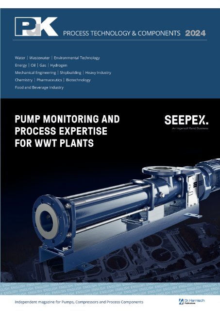
SEEPEX optimizes sewage sludge transport in<br />
the Ruhr region<br />
Pump monitoringand process expertise for<br />
sewage treatment plants<br />
The pump manufacturer Seepex installed its monitoring<br />
solution in one of the largest wastewater companies in Germany<br />
– the Ruhrverband – to optimize the transport of sewage sludge.<br />
The permanent, live monitoring of all parameters during pump<br />
operation optimizes performance, increases energy efficiency<br />
and brings a high degree of reliability and predictability to<br />
maintenance processes. (starting on page 14)<br />
Contents<br />
Editorial<br />
Total Cost of Ownership (TCO) 5<br />
Leading article<br />
Efficiency and quality 10<br />
Cover story<br />
SEEPEX optimizes sewage sludge transport in the Ruhr region 14<br />
Pumps and Systems<br />
High-efficiency pumps<br />
The best control 18<br />
Diaphragm metering pumps<br />
Diaphragm metering pumps prove their worth<br />
for critical mixing tasks in industrial oligonucleotide production 20<br />
Progressing cavity pumps<br />
Battery production in Europe drives pump manufacturers<br />
to new innovations 26<br />
Conical progressive cavity pump for demanding<br />
applications in the industrial and wastewater sectors 38<br />
Smart factory<br />
The intelligent path to the Smart Factory:<br />
How “pain points” become future-proof<br />
use cases thanks to the cloud 30<br />
Peristaltic pumps<br />
“Peristaltic pumps are an economical solution“ 33<br />
Screw pumps<br />
Advancing fluid conveyance beyond conventional boundaries 40<br />
Vacuum technology<br />
Vacuum systems<br />
Tracking the Big Bang 42<br />
Index of Advertisers 52<br />
Impressum 52<br />
Companies – Innovations – Products<br />
Pumps/Vacuum technology 56<br />
Trade fairs and events<br />
IFAT Munich <strong>2024</strong> 70<br />
IVS - INDUSTRIAL VALVE SUMMIT <strong>2024</strong> 72<br />
ACHEMA <strong>2024</strong> 74<br />
FILTECH <strong>2024</strong> 76<br />
VALVE WORLD EXPO <strong>2024</strong> 77<br />
DIAM & DDM 2025 78<br />
Compressors und Systems<br />
Machine room ventilation<br />
So that the packages do not run out of air 80<br />
Biogas backfeed<br />
Biogas Backfeed in Leoben 86<br />
Sustainability<br />
Sustainability on the rise 88<br />
Heat recovery<br />
Save money and benefit the environment 90<br />
<strong>Components</strong><br />
Plant documentation<br />
Getting started is easier than you think 93<br />
Frequency converter<br />
Multilevel technology: What it can do and what it enables 96<br />
Total cost of ownership<br />
Energy saving support 100<br />
Gaskets<br />
The complete, worry-free package for drinking water<br />
gaskets with KTW-BWGL conformity 102<br />
OT security<br />
OT security must be planned from the outset 104<br />
Sensors<br />
Sensors measure axle temperature:<br />
JUMO continues the success story of the TGV 106<br />
Drives<br />
Modern pioneer with a long tradition 108<br />
Seals<br />
New sealing options for CIP/SIP processes 110<br />
Companies – Innovations – Products<br />
Compressors/Compressed air/<strong>Components</strong> 112<br />
Technical Data Purchasing 117<br />
Screw spindle vacuum pumps<br />
Potential of surface structures for the<br />
reduction of vacuum gap flows 46<br />
Repair vs. replace<br />
When to repair vs. replace your vacuum pump: A guide 53<br />
8<br />
PROCESS TECHNOLOGY & COMPONENTS <strong>2024</strong>
FOR TEMPERATURES UP TO 200°<br />
ROBUST AND RESISTANT<br />
TO FOREIGN BODIES<br />
EASY TO SERVICE AND LOW M AINTENANCE<br />
ABRASIVE MEDIA<br />
INSENSITIVE TO AGGRESSIVE AND<br />
FOR HIGH PRESSURES UP TO 18 BAR<br />
YOU ARE LOOKING FOR A REAL<br />
GAMECHANGER?<br />
Visit us to learn more:<br />
Messe Frankfurt a.M.<br />
10. – 14.06.<strong>2024</strong><br />
Hall 8, Stand 64<br />
Resistant pumps from Vogelsang: always the right choice!<br />
Even in applications under extreme conditions, you can, from now on, benefit<br />
from Vogelsang pumps‘ economic efficiency, which is highly valued worldwide.<br />
Because thanks to our cross-industry experience, our uncompromising focus on<br />
solutions and the diversity of our portfolio, you will find exactly the right pump<br />
for your needs. From highly temperature resistant rotary lobe pumps especially<br />
designed to match the demands of the chemical and petrochemical industry<br />
through to the revolutionary HiCone ® progressive cavity pump for maximum<br />
efficiency and multiplied service life.<br />
VOGELSANG – LEADING IN TECHNOLOGY<br />
vogelsang.info
Leading article<br />
Efficiency and quality<br />
Prof. Dr.-Ing. Eberhard Schlücker<br />
Electricity is going to be our preferred<br />
form of energy in the future<br />
since it directly or indirectly<br />
replaces fossil fuels in everything<br />
from electric cars to homes and the<br />
chemical industry. CO 2<br />
and hydrogen<br />
are the magic bullets for indirect<br />
replacement.<br />
Hydrogen is universal in application<br />
and produced using electricity,<br />
while CO 2<br />
is harmful to our climate<br />
but will be an important raw material<br />
in the future. However, this means<br />
that we will need five to eight times<br />
more electricity or 10 to 16 times<br />
more electricity from wind and solar<br />
than today. This would only be possible<br />
if photovoltaic and wind power<br />
plants become far more efficient.<br />
Otherwise we will not have enough<br />
room, and resistance from the population<br />
is often encountered as well.<br />
We therefore have to import energy.<br />
Ammonia is no doubt the best<br />
option since its hydrogen content is<br />
high (110 Kg/m 3 ) and it only requires<br />
positive pressure of about 10 bar<br />
for transportation. The technology<br />
for recovering the hydrogen is available<br />
and relatively efficient. Australia<br />
is promising $1.50 per kilogram of<br />
hydrogen and the price is currently<br />
$2.00. Presumably this will be stored<br />
in ammonia. It will however cost<br />
more than that by the time it gets to<br />
us. Investments need to be made in<br />
production abroad, the construction<br />
of cargo ships, transportation, port<br />
receiving systems and the pending<br />
development of distribution structures<br />
in Europe. Since ammonia is<br />
toxic, one cannot expect to pump it<br />
through pipelines or to use it in municipal<br />
structures. Gas distribution<br />
networks in Germany are therefore<br />
being converted to hydrogen. Hydrogen<br />
currently costs € 4.55/kg in Germany.<br />
According to a publication of<br />
the Wuppertal Institute, hydrogen<br />
can be produced at lower cost in<br />
Germany compared to importing it<br />
in the form of ammonia. This is true<br />
in particular when the required electricity<br />
is produced domestically using<br />
photovoltaics (currently approx.<br />
8.5 cents/KWh, thus € 2.83/kg). We<br />
should therefore produce as much<br />
hydrogen as possible and sensible in<br />
Europe. This should allow us to meet<br />
our energy needs in conjunction<br />
with imports. However, we still have<br />
a long way to go and may experience<br />
occasional electricity shortages until<br />
we get there. There is at least some<br />
doubt whether energy imports will<br />
always proceed smoothly due to political<br />
changes. We should therefore<br />
turn this threat into an opportunity<br />
by developing products that are better<br />
than anything comparable in the<br />
world. Efficiency in all facets and durability<br />
are the keys to success. We<br />
need to build machinery and equipment<br />
that outperform all others in<br />
terms of efficiency and service life.<br />
In the examination of process<br />
technology, heat suggests itself as<br />
the focal point for assessing the efficiency<br />
of machinery (pumps, compressors<br />
etc.), equipment, electricity,<br />
materials and overhead.<br />
Heat energy and heating<br />
equipment<br />
Heat is a physical state that we need<br />
for technical applications and in our<br />
private life. Unfortunately, heat cannot<br />
be transported – or only in mobile,<br />
extremely well insulated heat<br />
storage vessels (costly). Heat should<br />
therefore be consumed where it is<br />
produced and one should always<br />
strive to maintain it at a high energy<br />
level where it is used. This means<br />
that heat dissipation losses should be<br />
minimised by good insulation or that<br />
waste heat should be utilised as far<br />
as possible. Heat flows can also be<br />
upgraded through compression, vapour<br />
recompression or heat pumps,<br />
thereby raising them to higher temperatures.<br />
In process technology, this means<br />
using heat cascades or heat upgrading<br />
methods, for example:<br />
1) The cold heat flow cools the warm<br />
flow, the warm flow cools the hot<br />
flow, and so forth! The hot flow<br />
can either be transformed back<br />
into electricity using a Carnot battery<br />
or the residual heat can be<br />
used for heating and returned to<br />
upgrading.<br />
2) If a flow of warm water is available<br />
that cannot be used any more, this<br />
could be provided to neighbours<br />
for heating or upgraded to reach<br />
a level that makes it usable again<br />
(for example, reheating from this<br />
level or, in case of gases or steam,<br />
compression or vapour recompression).<br />
3) If a hot flow is available that cannot<br />
be used any more, it should<br />
be stored in a mobile heat storage<br />
vessel or transformed into electricity<br />
using a Carnot battery<br />
4) When heating as well as cooling<br />
are required, both can be produced<br />
using a heat pump or the<br />
heat can be used for cooling generation,<br />
producing a warmer flow.<br />
Pumps and compressors<br />
The choice of a pump depends on<br />
the type of process used to produce<br />
a certain product. A rotary pump is<br />
the best choice when this meets the<br />
project requirements since it is costeffective<br />
and robust. However, its efficiency<br />
factor is poor in case of low<br />
flow rates or large control ranges.<br />
This raises the question of costs. The<br />
costs for a conveying task with a pressure<br />
increase of 10 bar, a flow rate<br />
of 10 m 3 /h and an efficiency factor of<br />
10 % are €19,352 when an electricity<br />
price of 0.285 cents/KWh is assumed<br />
10<br />
PROCESS TECHNOLOGY & COMPONENTS <strong>2024</strong>
Leading article<br />
Fig. 1: Conveying costs per year (8800 hours) for different pump efficiency factors, sample<br />
calculation for water at 10 m 3 per hour and 10 bar pressure increase.<br />
(published industry price). With an efficiency<br />
factor of 80 %, the costs decrease<br />
by 88 % to just € 2,418.<br />
You can easily determine the<br />
costs for different conveying tasks<br />
in the table to the right by multiplying.<br />
For example, the costs double<br />
when the pressure difference increases<br />
to 20 bar. The same applies<br />
for the delivery rate and electricity<br />
costs. Also note that the motor has to<br />
be matched to the respective conveying<br />
task. The motor of a pump with<br />
a 20 % efficiency factor is about four<br />
times larger compared to a pump<br />
with an efficiency factor of 80 %.<br />
Better efficiency factors for rotary<br />
pumps can however also be obtained<br />
through strategic control and regulation<br />
measures. [Hieninger]<br />
The efficiency factor of displacement<br />
pumps is better on average up<br />
to mid-range delivery rates. Such machines<br />
are rarely offered beyond that,<br />
even though they are clearly preferable<br />
for conveying highly viscous substances,<br />
higher pressures, or when a<br />
high dosing accuracy is required. Oscillating<br />
pumps achieve the highest<br />
dosing accuracy, often with the highest<br />
efficiency factor, at up to +- 0.5 %.<br />
Unfortunately, oscillating pumps<br />
have the largest footprint as a rule<br />
and also produce the greatest pulsation.<br />
Pulsation dampers can usually<br />
reduce this to a residual pulsation<br />
of about 1–3 %. This is classified<br />
as harmless, which is surely incorrect<br />
since oscillations and pressure<br />
surges as well as cavitation cause<br />
wear on pumps and other system elements.<br />
Choosing the right pump in<br />
terms of sustainability and service life<br />
is therefore a key task.<br />
A pressure surge passes through<br />
a system at the speed of sound<br />
(1480 m/s in water) and acts in all directions<br />
in pipes. It has a lot of force<br />
RECIPROCATING<br />
PUMPS TO API 674<br />
- Liquid ammonia pumps<br />
- Reactor feed pumps<br />
- Methanol pumps<br />
- Produced water injection pumps<br />
- Wash water pumps<br />
Pressure:<br />
Flow rate:<br />
50 – 4000 bar<br />
0,1 – 200 m³/h<br />
HAMPRO® HIGH-PRESSURE<br />
PROCESS TECHNOLOGY<br />
Hammelmann GmbH<br />
Carl-Zeiss-Straße 6-8<br />
D-59302 Oelde<br />
+49 (0) 25 22 / 76 - 0<br />
pp@hammelmann.de<br />
www.hammelmann-process.com
Leading article<br />
and frequently attacks sensors, expands<br />
pipes or deforms surfaces.<br />
This often leads to small relative<br />
movements between components<br />
that can degrade the structure. All<br />
other pumps including rotary pumps<br />
also cause pulsation, which can even<br />
be severe under some conditions but<br />
is usually tolerated. To improve the<br />
durability of pumps, we need to optimise<br />
the damping of oscillations and<br />
surges, and of course prevent cavitation.<br />
Since such dampers unfortunately<br />
do not exist yet, this is an engineering<br />
challenge.<br />
leading engineering challenges for<br />
compressors. Leakages may also occur<br />
depending on the type of gas.<br />
This is more of an issue the smaller<br />
the gas molecules are. Hydrogen, for<br />
example, is being discussed a great<br />
deal today. Its lubrication properties<br />
are extremely poor and it gets<br />
warmer, not colder, when the pressure<br />
is relieved at the start of the intake<br />
stroke. A liquid seal is highly suitable<br />
here but does of course require<br />
gas purification on the pressure side.<br />
In view of the energy loss through<br />
heat and leakage close to a factor of<br />
Fig. 2: Compression types of compressors: d1 isothermal; d2 polytropic, adiabatic with efficient<br />
cooling; d3 adiabatic or isentropic; d4 polytropic with additional heat input, e. g. from<br />
seal friction.<br />
The efficiency factor of compressors<br />
is highly dependent on cooling during<br />
the entire compression process.<br />
When seal friction occurs in addition,<br />
this results in polytropic compression<br />
in which the gas is additionally<br />
heated beyond compression heating.<br />
The hotter the gas, the more energy<br />
is needed for conveying. Heating<br />
of the gas during intake into the<br />
working chamber with hot walls is<br />
also problematic since it reduces the<br />
intake volume. Compared to isothermal<br />
compression in which the working<br />
chamber is cooled, ideally using<br />
a liquid, polytropic compression consumes<br />
at least twice the energy. Selecting<br />
appropriate cooling or perfectly<br />
separating coolant droplets<br />
of the internal coolant are thus the<br />
two, gas purification on the pressure<br />
side should be amortised quickly.<br />
The energy demand for a target pressure<br />
also increases the lower the actual<br />
intake pressure is. Therefore,<br />
the pressure loss on the intake side<br />
should be minimised as far as possible.<br />
The same applies for the seal<br />
friction. The area below the curves<br />
and lines in Figure 2 represents the<br />
required compression energy.<br />
The efficiency factor of compressors<br />
depends on the following aspects:<br />
1) A lack of effective cooling results in<br />
adiabatic compression. When relatively<br />
high seal friction on the piston<br />
is added, we have polytropic<br />
compression. The consumption of<br />
energy is 150 % higher compared<br />
to isothermal compression. The<br />
hotter the gas at the end of conveying,<br />
the more conveying energy.<br />
2) Gas heating during intake is also<br />
problematic; compression heating<br />
results in hot working chamber<br />
walls. The incoming gas is heated<br />
and expands during intake. This<br />
considerably reduces the intake<br />
volume.<br />
3) Every piston compressor in the<br />
classic design has a dead space.<br />
This is the remaining space at upper<br />
dead centre, which first has<br />
to be depressurised on the intake<br />
stroke before the intake as such<br />
can begin. When conveying hydrogen,<br />
it also heats up when the<br />
pressure is relieved.<br />
4) The intake with pressure loss<br />
means that the actual intake pressure<br />
is lower than the static intake<br />
pressure. While the difference is<br />
small as a rule, it nevertheless has<br />
a negative effect since compression<br />
starting at a lower pressure<br />
consumes the most energy per<br />
compression stroke.<br />
5) A pressure loss also occurs on the<br />
pressure side. However, it occurs<br />
in the upper pressure range and is<br />
therefore the smallest loss in this<br />
list.<br />
6) Leakage on the piston: Depending<br />
on the gas type and its lubricating<br />
properties, the seal suffers<br />
considerable wear and thus also<br />
an appreciable leakage flow. Both<br />
are particularly high for hydrogen<br />
since it does not lubricate. A lot if<br />
research is therefore being done in<br />
this area as well.<br />
7) With poorly lubricating gases<br />
(such as hydrogen), sliding movements<br />
of the compressor valves<br />
can be expected to occur during<br />
valve closing, from the initial contact<br />
until the final limit of travel is<br />
reached, which can cause wear.<br />
The functionally best solution is a<br />
liquid piston or a layer of liquid over<br />
the metallic piston (piston works upward).<br />
This can reduce the dead space<br />
to zero. Leakage is also zero due to<br />
the barrier effect of the liquid and the<br />
piston seal is lubricated, which can<br />
12<br />
PROCESS TECHNOLOGY & COMPONENTS <strong>2024</strong>
Leading article<br />
extend the maintenance intervals. A<br />
nearly isothermal compression can<br />
be achieved with the proper layout.<br />
Cooling with a liquid means that<br />
droplets are produced so that filter<br />
technology is required on the pressure<br />
side. Considering that the loss<br />
of energy through heat and leakage<br />
is in the range of more than a factor<br />
of two compared to isothermal<br />
compression and the drive motor<br />
has twice the output, meaning its approximate<br />
cost is at least 50 % more,<br />
gas purification on the pressure side<br />
should be amortised quickly and may<br />
in fact be less costly than one year of<br />
wasted energy and leakage.<br />
Chemical and biological<br />
production facilities<br />
The smaller the system with the same<br />
material flow, the lower the friction<br />
pressure loss. This should be taken<br />
into account in system planning. Some<br />
tests have already been conducted in<br />
this direction, but they stalled at the<br />
standardisation stage and a breakthrough<br />
was not achieved. We may<br />
have to rethink plant engineering and<br />
construction. One example that was<br />
intensively discussed are rails around<br />
a chemical plant, on which tank cars<br />
are moved e. g. from A to B etc. in order<br />
to be filled or emptied, transporting<br />
materials and goods. This would<br />
definitely open up new opportunities<br />
since there would no longer be tanks<br />
inside the plant. At most, there would<br />
be reactors if these could not be relocated<br />
to a rail car as well. In this case<br />
the plant would be reduced to pipework<br />
only. Physical separation could<br />
also be realised, permitting function<br />
pools with storage in moveable tanks.<br />
The number of pipe elbows would<br />
definitely be reduced as well. For<br />
those that cannot be eliminated, recent<br />
developments cut the additional<br />
loss in pipe elbows almost in half.<br />
When the plant as such consists only<br />
of pipework, cross-section changes<br />
that deplete energy are hardly needed<br />
and the length of the pipework<br />
could be reduced. In addition, many<br />
systems need to be pressurised and<br />
the pressure is usually discharged<br />
without being utilised.<br />
Energy recovery using expansion<br />
machines could be amortised relatively<br />
quickly.<br />
General rules:<br />
1) Since friction always consumes energy,<br />
optimal lubrication and materials<br />
with sliding properties or<br />
pressure lubrication are important.<br />
2) A noisy machine consumes more<br />
energy than a machine that runs<br />
quietly. Noise can also be indicative<br />
of wear.<br />
3) Heat distortion due to uneven thermal<br />
expansion can lead to damage<br />
caused by wear or loud machine<br />
noises. When a machine becomes<br />
louder after starting up, this can be<br />
an indicator of such effects.<br />
4) Vibrations in a pipe section can be<br />
indicative of small pressure surges<br />
or oscillations that energetically<br />
match the resonance frequency<br />
of the pipe section. This indicates<br />
oscillations in the system and increases<br />
the probability of damage.<br />
5) Cavitation is loud when bubbles<br />
implode on the walls and usually<br />
quiet when the bubbles implode in<br />
the fluid space. The latter is generally<br />
not harmful. However, cavitation<br />
that is barely audible but can<br />
nevertheless cause damage also<br />
occurs. Experience and learning<br />
processes are required here.<br />
Literature<br />
[Hieninger] Energy Efficiency (2021)<br />
14:23 https://doi.org/10.1007/s12053-<br />
021-09932-5<br />
The Author:<br />
Prof. Dr.-Ing. Eberhard Schlücker<br />
Prof. (ret.), advisor on hydrogen<br />
and energy issues<br />
We put the filling<br />
into the strudel!<br />
MORE!<br />
Hygienic WANGEN PUMPS pump<br />
medium-specifically, gently and reliably.
Cover story<br />
Pump monitoring and process expertise for<br />
sewage treatment plants<br />
SEEPEX optimizes sewage sludge transport<br />
in the Ruhr region<br />
Every river needs clean water.<br />
Treated wastewater from approximately<br />
two million people feeds the<br />
river that gives its name to Germany’s<br />
largest urban area, the Ruhr.<br />
For the Ruhrverband, digital monitoring<br />
solutions from the internationally<br />
renowned specialist SEEPEX<br />
ensure that the sludge treatment<br />
process remains under control.<br />
After a successful test phase of the<br />
pump monitoring system, Ruhrverband<br />
is convinced that permanent<br />
live monitoring of important parameters<br />
during pump operation<br />
improves performance, increases<br />
energy efficiency and brings high reliability<br />
and predictability to maintenance<br />
processes.<br />
Fig. 1: Ruhrverband, one of Germany’s largest waste water operators, treats the wastewater<br />
of approx. 2.2 million people in the Ruhr area every day. (Source: Ruhrverband, Essen Kupferdreh<br />
sewage treatment plant)<br />
Ruhrverband and SEEPEX have a<br />
long-standing partnership in the field<br />
of sewage sludge conveying. The<br />
Bottrop-based company’s powerful<br />
progressive cavity pumps transport<br />
viscous sludge over long distances to<br />
treatment plants. In two wastewater<br />
treatment plants in the city of Essen,<br />
pump monitoring solutions optimize<br />
processes on a permanent basis.<br />
Since 2021, the pump monitoring system<br />
has been recording sensor data<br />
for analysis. The goal is to optimize<br />
the operating performance of the installed<br />
pumps and reduce their maintenance<br />
requirements. The technology<br />
has proven to be successful and is<br />
now in permanent use.<br />
A challenging process over<br />
long distances<br />
Both partners faced the special challenge<br />
of long pumping distances of<br />
up to eight kilometers as well as with<br />
varying quantities and changing viscosity<br />
of the pumped medium. The<br />
result is a demanding and, in some<br />
cases, complex process with a great<br />
Fig. 2: Seepex installed digital monitoring solutions at two sewage treatment plants in the<br />
south of Essen, thereby optimizing sewage sludge transport. (Source: Seepex)<br />
deal of potential for optimization. The<br />
customer hoped that pump monitoring<br />
would provide suggestions for improvements<br />
in terms of operating parameters,<br />
operating times and energy<br />
consumption by analyzing pump operation<br />
and process conditions over<br />
a long period. Critical pressure conditions<br />
and wear were also areas of<br />
focus. Consequently, the pump monitoring<br />
system recorded pump data<br />
such as flow, pressure, vibration and<br />
14 PROCESS TECHNOLOGY & COMPONENTS <strong>2024</strong>
Cover story<br />
temperature. This allowed the system<br />
to monitor components and process<br />
conditions in real-time.<br />
The one-year pilot project involved<br />
two pumps conveying primary<br />
sludge from different locations<br />
for further treatment. One NS 70-24<br />
pump transports the primary sludge<br />
from the Essen-Kupferdreh WWTP<br />
over a distance of eight kilometers<br />
to the sludge treatment facility. The<br />
other BN 130-12 progressive cavity<br />
pump transports the sludge from the<br />
Essen-South WWTP over a distance of<br />
six kilometers. The task was to match<br />
both conveying methods to the capacity<br />
of the sludge treatment facility.<br />
Problem detection and<br />
root-cause analysis<br />
In February 2021, SEEPEX installed<br />
its pump monitoring units at the two<br />
sites. The scope of supply included<br />
the pump monitoring hardware, a<br />
customized sensor package, as well<br />
as the communication infrastructure<br />
and Connected Services for collecting,<br />
monitoring and analyzing the<br />
data. “SEEPEX supported Ruhrverband<br />
with monthly reports, presentation<br />
of findings and recommendations<br />
for action based on algorithms<br />
and our expert knowledge,” says the<br />
Product Manager of Digital Solutions<br />
at SEEPEX.<br />
Early in the analysis, SEEPEX experts<br />
were able to uncover previously unknown<br />
problems and determine the<br />
underlying causes. For example, discharge<br />
pressures were high and<br />
sometimes outside the pump’s specifications.<br />
The experts quickly determined<br />
that resonant frequencies<br />
overstressed the mechanical components,<br />
which was causing loosened<br />
screw fittings and a broken tie rod.<br />
Pump monitoring made the condition<br />
of the rotor and stator transparent<br />
as the test phase progressed.<br />
SEEPEX was able to determine the<br />
ideal time for their replacement with<br />
one month’s notice. This way, the customer<br />
was able to plan the maintenance<br />
work ahead of time and avoid<br />
process interruptions. On the other<br />
hand, the water association was able<br />
to fully utilize the wearing parts without<br />
jeopardizing process reliability.<br />
Further adjustments increased the<br />
service life of the rotor and stator by<br />
more than 50 %, which translates into<br />
annual savings of more than € 6,000<br />
per pump.<br />
25 % less power to operate<br />
By determining three key factors influencing<br />
energy consumption, the<br />
team of the pump manufacturer was<br />
able to identify potential energy cost<br />
savings of more than 25 % and ultimately<br />
recommend actions to improve<br />
energy efficiency. Ruhrverband<br />
implemented process control adjustments<br />
in close coordination with<br />
SEEPEX. Overall, Ruhrverband was<br />
impressed with the detailed energy<br />
analysis of its pumps. The monitoring<br />
system provides a clear overview<br />
of energy consumption and specific<br />
energy costs per cubic meter of<br />
pumped sludge. From now on, continuous<br />
pump monitoring will ensure<br />
optimal process conditions and consistently<br />
low energy consumption.<br />
Predictable maintenance cycles<br />
“The main benefit of SEEPEX’s continuous<br />
condition monitoring, analysis<br />
and reporting is the ability to predict<br />
maintenance cycles, which significantly<br />
reduces operating costs,” explains<br />
the Project Manager for Digitali zation<br />
Projects at Ruhrverband. “We were<br />
very grateful for the in-depth analysis<br />
on how to monitor wear and minimize<br />
the energy consumed per cubic<br />
meter of sludge pumped.”<br />
The compact, easy-to-understand<br />
monthly report, which summarizes<br />
key performance indicators (KPIs),<br />
trends and error messages, is invaluable<br />
to Ruhrverband. Through close<br />
cooperation, the monthly report has<br />
been continuously adapted to the<br />
needs of Ruhrverband. Incidentally,<br />
PROCESS TECHNOLOGY & COMPONENTS <strong>2024</strong><br />
15
Cover story<br />
Fig. 3: Permanent condition monitoring as well as pump and process expertise summarized in a monthly status report with recommendations<br />
for action. (Source: Seepex)<br />
Ruhrverband<br />
Ruhrverband is a municipal water utility plant that provides water to<br />
4.6 million people and wastewater treatment to 60 cities in the Ruhr region.<br />
Its 65 wastewater treatment plants treat wastewater from 2.2 million<br />
people and businesses in the region every day, ensuring that only purified<br />
water is returned to the river.<br />
Pump Monitoring and Connected Services<br />
SEEPEX Pump Monitoring provides comprehensive monitoring and optimization<br />
of progressive cavity pumps to protect components and improve<br />
maintenance and operation. Digital monitoring minimizes life cycle costs<br />
and increases overall efficiency. Using sensors for temperature, pressure<br />
or flow, SEEPEX Pump Monitoring can make the pump's operating data<br />
available in the intelligent cloud-based platform. This allows users to continuously<br />
monitor the pump and view live data. Users can also set alarms<br />
and trends, and log all data for later performance analysis. The ability to<br />
access the pump's performance data at any time and respond quickly to<br />
changes through notifications helps to avoid unplanned downtime. Additionally,<br />
the pump only reports when it notices that something is wrong.<br />
all SEEPEX customers will benefit<br />
from the results in the future - the extended<br />
monthly report is now part of<br />
the monitoring solution.<br />
Pump monitoring benefits<br />
at a glance<br />
– Continuous monitoring of pump<br />
status and components provides<br />
visibility across applications and<br />
processes<br />
– Early notification of deviations<br />
from optimal condition<br />
– Increased component life<br />
– Determine optimal operating<br />
point with minimum energy<br />
consumption<br />
In addition to providing convenient service for critical processes, the benefits<br />
include improved spare parts utilization. The knowledge gained from<br />
pump monitoring can be used to optimize maintenance cycles. The measurement<br />
data can be accessed via an app on a smartphone, tablet or from<br />
a control room.<br />
SEEPEX offers Connected Services, another module in its digital portfolio,<br />
to analyze and use the available data at any time. Benefits of the cloudbased<br />
service include predictive maintenance through early warnings and<br />
wear prediction, and full access to historical, live and trended data for advanced<br />
analysis.<br />
SEEPEX GmbH, Bottrop, Germany<br />
www.seepex.com<br />
16 PROCESS TECHNOLOGY & COMPONENTS <strong>2024</strong>
GREEN EFFICIENT TECHNOLOGIES<br />
The independent media platform for<br />
energy supply, efficiency enhancement and<br />
alternative energy sources and storage<br />
Sustainable opportunities in process<br />
technology<br />
Circular economy in the industrial<br />
production process<br />
Topics H 2<br />
, Synthetic Fuels, Water,<br />
Solar & Photovoltaics, Wind Power,<br />
Bioenergy, Geothermal Energy, Battery<br />
<strong>Technology</strong>, System Integration and<br />
other alternative options<br />
Dr. Harnisch Verlags GmbH · Eschenstr. 25 · 90441 Nuremberg · Tel.: +49 (0) 911 - 2018 0 · info@harnisch.com · www.harnisch.com
Pumps and Systems<br />
High-efficiency pumps<br />
High-efficiency pumps<br />
The best control<br />
Jochen Krings<br />
High energy costs are once again<br />
calling attention to the savings potential<br />
of circulating pumps. But<br />
how big are the differences between<br />
the latest models and older<br />
ones? And when is it worth it to replace<br />
them?<br />
The key to the enormous efficiency<br />
gains from modern high-efficiency<br />
pumps is their motor design and control.<br />
The Grundfos Alpha2 series, for<br />
example, is equipped with a highly<br />
efficient permanent magnet motor.<br />
Unlike conventional asynchronous<br />
motors, this one does not require<br />
ener gy to magnetise the rotor, making<br />
it around 30 per cent more efficient.<br />
As well as this, the pump’s<br />
components have been optimised to<br />
reduce typical losses to a minimum.<br />
These include the stator windings,<br />
eddy currents in the stator and rotor<br />
fins, the flow of current in the rotor<br />
rods and end rings, and friction in the<br />
bearings. The hydraulic has been optimised<br />
down to the last detail using<br />
computational flow simulations. The<br />
impeller, for example, has been completely<br />
redesigned from previous<br />
generations to convert the rotation of<br />
the motor shaft into flow even more<br />
efficiently.<br />
The materials also help to improve<br />
efficiency. The permanent magnet rotor<br />
is made from neodymium, and the<br />
motor can is made from composite<br />
material. The housing has a cataphoretic<br />
coating (applied using an electrochemical<br />
dip coating process) that not<br />
only provides a high degree of protection<br />
from corrosion, but also reduces<br />
flow resistance thanks to its especially<br />
even surface. Here too, the developers<br />
have fine-tuned every detail to<br />
achieve maximum efficiency.<br />
Smart control<br />
The introduction of electronic speed<br />
control in the 1990s was an important<br />
step in making pumps more efficient.<br />
There has, however, been further<br />
significant progress in this area<br />
too. Conventional control only returns<br />
an output variable such as the<br />
differential pressure back to the control<br />
variable. The special system conditions,<br />
such as the loss coefficients<br />
of pipes, fixtures, boilers and radiators,<br />
are largely ignored. As a result,<br />
the pump does not run on the system’s<br />
optimum control curve.<br />
Modern self-adapting pumps<br />
such as the Grundfos Alpha2, on the<br />
other hand, regularly analyse the system<br />
conditions and optimise the position<br />
of the proportional pressure<br />
Fig. 2: The latest high-efficiency pumps, such as the Alpha2, are significantly more efficient<br />
even than their predecessors, which were already among the most efficient of their time<br />
Fig. 1: Permanent motor, hydronic optimisation down to the last detail and smart control<br />
enable the highest level of efficiency (Grundfos Alpha2) (All images: Grundfos)<br />
curve automatically. The advantage<br />
of this is that the pump always runs<br />
on the optimum curve, so it does not<br />
consume more energy than necessary.<br />
It is not affected by short-term<br />
fluctuations in demand as these are<br />
compensated for by the proportional<br />
pressure control. The AutoAdapt<br />
technology also simplifies the commissioning<br />
process. All the installer<br />
needs to do is connect the power<br />
supply, and the pump will take care<br />
of optimising its settings itself.<br />
18 PROCESS TECHNOLOGY & COMPONENTS <strong>2024</strong>
Pumps and Systems<br />
High-efficiency pumps<br />
Significant efficiency gains<br />
Since the EuP Directive came into<br />
force in 2013, virtually the only circulating<br />
pumps installed in Germany<br />
have been high-efficiency pumps.<br />
Nevertheless, there are still millions<br />
of old uncontrolled pumps running<br />
in boiler rooms. These are obviously<br />
worth replacing. A modern highefficiency<br />
pump is around 90 per<br />
cent more efficient than an old, uncontrolled<br />
circulating pump with<br />
the previous energy efficiency class<br />
D rating. For pumps with a typical<br />
size and standard load profile, this<br />
reduces power consumption by approximately<br />
450 kWh per year. With<br />
savings of some 150 euros per year,<br />
even without subsidies the new<br />
pump will have paid for itself within<br />
just a few years.<br />
est Alpha2 today will lead to savings<br />
of more than 100 kWh per year.<br />
Thanks to vast improvements in<br />
efficiency, the flow rates of pumps<br />
have changed so much that an existing<br />
pump can often be replaced<br />
with a smaller type and still provide<br />
the same performance. For example,<br />
an old Magna 40-100 can be replaced<br />
with a Magna3 32-100 or even<br />
a Magna3 25-120, depending on the<br />
operating point. This means that significant<br />
investment cost savings can<br />
be made too. With the right adapter<br />
sets provided for the Magna3 range,<br />
the smaller types can be adapted to<br />
the situation in which they are being<br />
installed. For example, pipe fitting<br />
models can be adapted to an existing<br />
flange connection and the installation<br />
length can be increased from<br />
180 to 220 mm.<br />
Fig. 4: The latest Alpha2 and Alpha3 models<br />
enable a simple hydronic balancing process<br />
that is eligible for a subsidy and saves additional<br />
energy<br />
Fig. 3: If a pump can be replaced with a smaller size to achieve the same flow rate, adapter<br />
sets can be used to adapt the pump to the situation where it is being installed (Grundfos<br />
Magna3)<br />
with the pump and is guided through<br />
the balancing process step by step by<br />
the GO Balance app. This simple procedure<br />
takes less than two hours for<br />
a typical single-family home and is eligible<br />
for a subsidy.<br />
Experience has shown that hydronic<br />
balancing increases the efficiency<br />
of the heating system by 10<br />
to 20 per cent. Despite this, it is estimated<br />
that up to 10 million German<br />
heating systems have not yet been<br />
balanced. This makes it all the more<br />
worthwhile to combine a pump replacement<br />
with hydronic balancing –<br />
yet another reason to get a modern<br />
high-efficiency pump.<br />
A less obvious point is that current<br />
high-efficiency models perform considerably<br />
better even than newer<br />
pumps. This becomes clear when<br />
looking at the best-selling Grundfos<br />
Alpha series, each generation of<br />
which was among the most efficient<br />
in its class at the time. Introduced in<br />
2005, the energy-saving Alpha Pro<br />
model with permanent magnet motor<br />
and integrated frequency converter<br />
was around 62 % more efficient than<br />
the original Alpha released in 2000.<br />
The latest Alpha2 generation is 68 %<br />
more efficient even than the Alpha<br />
Pro, and consumes 88 % less energy<br />
than the 2000 model. Replacing an<br />
energy-saving Alpha Pro with the lat-<br />
Replace and balance<br />
Today’s models, such as Alpha2 or<br />
Magna3, have been hydronically optimised<br />
so much that they are almost<br />
at the limits of what physics will allow.<br />
There are still further developments<br />
taking place, however, mainly<br />
in the area of digital integration. One<br />
example of this is hydronic balancing.<br />
When they leave the factory, both<br />
models are prepared for a process,<br />
developed by Grundfos, in which the<br />
pump provides the necessary data.<br />
The Alpha3 has the necessary wireless<br />
interface already built in, while<br />
the Alpha2 requires the Alpha Reader<br />
tool. The installer pairs a smartphone<br />
The Author: Jochen Krings,<br />
Professional Relations,<br />
Grundfos GmbH, Erkrath, Germany<br />
www.grundfos.de<br />
PROCESS TECHNOLOGY & COMPONENTS <strong>2024</strong><br />
19
Pumps and Systems<br />
Diaphragm metering pumps<br />
Production of biomolecules for pharmaceuticals<br />
Diaphragm metering pumps prove their<br />
worth for critical mixing tasks in industrial<br />
oligonucleotide production<br />
Dr. Hans-Joachim Johl<br />
The size of oligonucleotides lies between<br />
that of small, low-molecular-weight<br />
active pharmaceutical<br />
ingredients (APIs) and high-molecular-weight<br />
active pharmaceutical ingredients<br />
such as mAbs (monoclonal<br />
antibodies). Production facilities<br />
for the manufacture of oligonucleotides<br />
must be able to handle flammable,<br />
toxic compounds as well as<br />
meet hygienic standards to ensure<br />
biological integrity. Above all, however,<br />
they must be flexible and able<br />
to be scaled up from pilot plants<br />
so that they can ideally synthesize<br />
and purify a wide variety of drugs.<br />
In addition to standardized platform<br />
technologies, customer-specific<br />
GMP-compliant systems are<br />
also needed. Diaphragm metering<br />
pumps in these systems can meet<br />
the challenges of extreme chemical<br />
syntheses in the upstream process<br />
and also be used in contamination-free<br />
downstream processes.<br />
The flexible production of toxic and<br />
flammable fluid mixtures with widely<br />
varying flow rate requirements is<br />
particularly important here.<br />
From rare diseases to chronic indications,<br />
the demand for oligonucleotide-based<br />
drugs is steadily increasing.<br />
Oligonucleotides are short, small<br />
(= oligo) sections of genetic sequences<br />
(RNA and DNA). Nucleotides are<br />
the building blocks of nucleic acids<br />
occurring in DNA and RNA chains. Oligonucleotides<br />
are therefore among<br />
the most important components of<br />
modern molecular biology. One of<br />
the most important ways of producing<br />
oligonucleotides with modified<br />
nucleotides for therapeutic purposes<br />
is industrial DNA and RNA synthesis.<br />
In contrast to the frequently used,<br />
biopharmaceutically produced drugs<br />
that target proteins, oligonucleotides<br />
target disorders in the genetic<br />
code that are the cause of specific<br />
diseases. This makes them predestined<br />
for the treatment of previously<br />
incurable rare diseases, including<br />
neuronal diseases. The first antisense<br />
oligonucleotide drug was approved in<br />
1998 as Fomivirsen, under the trade<br />
name Vitravene, for the treatment of<br />
CMV virus in AIDS patients. 1 Several<br />
others followed, including Partisiran,<br />
approved in 2018 under the trade<br />
name Onpattro, a lipid nanoparticleformulated<br />
drug that is one of the<br />
newer oligonucleotide therapies for<br />
polyneuropathy. Although various<br />
oligonucleotide drugs have already<br />
been approved by the authorities,<br />
they have not yet been established<br />
on an industrial commercial scale.<br />
Many other drugs are currently in the<br />
clinical phase prior to industrial production<br />
and are therefore the focus<br />
of ongoing research efforts, which<br />
increasingly include economic and<br />
quantitative aspects.<br />
Challenge: Economical production<br />
of oligonucleotides<br />
As a result, many specialized companies<br />
are focusing on efficient and safe<br />
GMP production of oligonucleotides<br />
using suitable production facilities.<br />
The aim is to maximize yield while<br />
maintaining high purity. This means<br />
that manufacturers of active pharmaceutical<br />
ingredients are faced with<br />
the task of making their own production<br />
processes more and more economical<br />
and robust so that they can<br />
be scaled up from laboratory or pilot<br />
scale to industrial GMP production<br />
with the highest possible yield in synthesis<br />
and downstream steps, without<br />
sacrificing quality or neglecting<br />
economic aspects.<br />
An important step for oligonucleotide<br />
processes is known as media<br />
dilution, where the concentrations<br />
of a synthesized solution are<br />
adjusted. More concentrated storage<br />
solutions are continuously di-<br />
Fig. 1: Production facilities for the manufacture of oligonucleotides must be able to handle<br />
flammable, toxic compounds as well as meet hygienic standards to ensure biological<br />
integrity. (Source: LEWA)<br />
20 PROCESS TECHNOLOGY & COMPONENTS <strong>2024</strong>
Pumps and Systems<br />
Diaphragm metering pumps<br />
Fig. 2: The inline dilution systems use multihead<br />
diaphragm metering pumps specially<br />
designed for pharmaceutical applications.<br />
(Source: LEWA)<br />
luted to achieve the desired working<br />
concentration. The choice of solution<br />
depends on the subsequent steps in<br />
the downstream process. After the<br />
actual chemical synthesis, in which<br />
the nucleotides are added one after<br />
the other to a growing chain, the<br />
synthesized products undergo what<br />
is known as deprotection and purification<br />
steps to remove unwanted<br />
by-products. Accompanying process<br />
and quality control, e. g. in the form<br />
of mass spectrometry, ensures that<br />
the end product is within the defined<br />
specification window.<br />
Continuous flow regulation<br />
and keep the fluid quantity constant<br />
by controlling the speed of the metering<br />
pumps precisely. Pressure control<br />
valves with integrated electronically<br />
controlled pneumatic damping installed<br />
in the output-side manifold<br />
maintain low fluctuation and keep<br />
the mixing flow almost constant. This<br />
also applies to the pressure: Fluctuations<br />
are undesirable for the built-in<br />
measuring chains and interfere with<br />
the separation processes in the chromatography<br />
columns. Gas phase<br />
components and any temperature increase<br />
also have to be prevented.<br />
After the mixing result is combined<br />
in the manifold, the ratio is analyzed<br />
using appropriate measurement<br />
technology, e. g. via the pH<br />
value and electrical conductivity. After<br />
programming the stored target<br />
values in the higher-level control system,<br />
these are available as different<br />
methods for system control. The recorded<br />
measured values are determined<br />
at a high sampling rate and<br />
continuously evaluated centrally. The<br />
pumps used must be corrosion-resistant,<br />
hygienic and have a robust design<br />
for continuous use. LEWA has detailed<br />
knowledge and many years of<br />
experience in high-precision metering<br />
and mixing thanks to its de cades in<br />
the field of pump supply for the process<br />
chromatography of major OEMs.<br />
And this has also benefited the design<br />
of correspon ding mixing and metering<br />
systems for oligo synthesis customers<br />
for some years now.<br />
Fig. 4: Pressure control valve with damping<br />
properties equipped with an electronic pilot<br />
valve for automatic control.<br />
(Source: EQUILIBAR)<br />
Package units for individual<br />
dilution tasks<br />
The dilution systems designed and<br />
described are not standard systems,<br />
but customized inline metering and<br />
dilution systems that are designed<br />
and constructed as package units<br />
(PU) for the respective downstream<br />
process. A system of this type can<br />
have up to five process inlets and<br />
outlets – sometimes more – as well<br />
as various other connections, for example<br />
for flushing or waste water, to<br />
ensure flexible and continuous fluid<br />
transport. A cycle of chemical reactions<br />
is initiated by feeding in the<br />
respective synthesis fluids. Individual<br />
nucleotides are coupled and the<br />
desired modified chain sequence is<br />
In order to meet increased demand<br />
by expanding production capacities,<br />
precise and continuously operating<br />
inline dilution systems must be provided.<br />
One of the biggest challenges<br />
here is maintaining a consistently reproducible<br />
quality of the required<br />
buffer within the narrow window for<br />
permissible concentration deviations.<br />
Among other things, continuous<br />
monitoring of the flow rates and the<br />
resulting dilution ratios is essential<br />
for this. Therefore, inline dilution systems<br />
typically consist of several channels<br />
with valves, where each channel<br />
is equipped with a multi-head<br />
diaphragm pump and a Coriolis flow<br />
meter. They measure the mass flow<br />
Fig. 3: Pressure control valves with integrated electronically controlled pneumatic damping<br />
installed in the output-side manifold maintain low fluctuation and keep the mixing flow almost<br />
constant. (Source: LEWA)<br />
PROCESS TECHNOLOGY & COMPONENTS <strong>2024</strong><br />
21
Pumps and Systems<br />
Diaphragm metering pumps<br />
formed by repeating the reactions.<br />
Due to the highly flammable fluids<br />
required, including solvents such as<br />
ethanol, isopropanol, toluene and<br />
acetonitrile, the systems often have<br />
to be designed for use in Ex zone 2 IIB<br />
T3. Inert gas (nitrogen) further protects<br />
the process. The inline dilution<br />
system for aqueous fluid mixtures in<br />
the downstream area provides highaccuracy<br />
buffer solutions for semicontinuous<br />
chromatography after<br />
synthesis. HPLC, ion pairing reversed<br />
phase (IP-RP) and ion exchange (IEX)<br />
chromatography columns are used<br />
for chromatographic purification. 2<br />
Individual dilution tasks can thus<br />
be implemented precisely and flexibly.<br />
Several 1,000 liters of solvent<br />
and aqueous fluids are required per<br />
kilogram of active ingredient. In order<br />
to be able to implement large<br />
adjustment ranges from a few liters<br />
per hour up to 6,000 l/h, it must be<br />
possible to call up an automated<br />
and continuous supply of changing<br />
mixtures for the downstream purification<br />
process via the system control.<br />
Several multi-head diaphragm<br />
metering pumps specially designed<br />
for pharmaceutical applications are<br />
used here. Their phase-shifted drive<br />
charac teristics, typically with three<br />
to five pump heads, enable a lowpulsation<br />
overall flow rate. Thanks<br />
to the back pressure-independent<br />
characteristic curve, the entire metering<br />
and mixing process for oligonucleotide<br />
production is reliably continuous<br />
and absolutely reproducible<br />
at all times. No other type of pump<br />
can achieve stable linear and step<br />
gradients as well as reliable gradient<br />
charac teristics more consistently.<br />
These hermeti cally tight pumps<br />
rule out backflow or plunger packing<br />
problems.<br />
Large adjustment ranges and high<br />
production reliability<br />
Because the production of dilution<br />
solutions sometimes requires very<br />
different flow rates, the systems<br />
must be designed to be flexible. One<br />
practical example required flow rates<br />
of a minimum of 40 l/h and a maximum<br />
of 2,500 l/h. A total of five LEWA<br />
ecodos hygienic diaphragm metering<br />
Fig. 5: Basic flow diagram of a flexible dilution system from concentrates (example). (Source: LEWA)<br />
pumps were integrated into this system<br />
in order to be able to cover this tent, such as the more corrosion-re-<br />
and steels with a higher alloy con-<br />
large adjustment range flexibly. The sistant 1.4529 stainless steel or Hastelloy<br />
for fluids with a high chloride<br />
pump heads are equipped with mechanically<br />
actuated, four-layer sandwich<br />
safety diaphragms. Since the able for metering highly corrosive<br />
content. This makes the pumps suit-<br />
area behind the diaphragm is subject and flammable fluids in oligonucleotide<br />
production over the long term.<br />
to strictly regulated clean room environmental<br />
conditions, contamination The patented four-layer PTFE sandwich<br />
diaphragm also helps here: It<br />
with operating materials or process<br />
fluids cannot occur. Due to the GMP is extremely stable and ensures that<br />
environment, which strives for high operation can be continued safely<br />
even in the event of a diaphragm<br />
integrity with regard to contamination<br />
of any kind, hygienic versions of rupture, thus providing a high level of<br />
the pumps must also be used in this process safety. In an emergency, the<br />
area of downstream processing. This integrated diaphragm rupture signaling<br />
system immediately reports a<br />
goes hand in hand with accep tance<br />
test certificates 3.1 and consis tently corresponding fault during operation<br />
certified construction materials, such without contaminating the rest of the<br />
as FDA, USP or AOF certificates of process line. Only hermetic plunger<br />
conformity. All metal parts in contact diaphragm pumps offer such a high<br />
with the fluid are mechanically and level of production reliability.<br />
additionally electropolished and have<br />
a surface roughness of Ra ≤ 0.5 µm. Precise control and continuous<br />
Thanks to the hygienic design of the monitoring<br />
diaphragm body, which almost completely<br />
eliminates dead spaces, the In terms of control, the use of a servomotor<br />
and an intelligent control sys-<br />
pumps can be cleaned in the CIP process<br />
very easily and without prior dismantling.<br />
requirement profiles to be impletem<br />
enable different customer-side<br />
The EHEDG EL Class 1 certificate<br />
for the ecodos pump type used to be extended up to 1:200. The<br />
mented and the adjustment range<br />
is a decisive proof of quality with regard<br />
to the excellent inline cleanabi-<br />
via the stroke length and the speed<br />
flow rate is traditionally adjusted<br />
lity of the fluid-side pump head. The of the pump motor via the frequency<br />
of an inverter. In newer concepts,<br />
materials used are 1.4435 stainless<br />
steel with a low delta ferrite content the speed of a fanless synchronous<br />
22 PROCESS TECHNOLOGY & COMPONENTS <strong>2024</strong>
Pumps and Systems<br />
Diaphragm metering pumps<br />
motor or permanent magnet synchronous<br />
motor (PMSM) is variable<br />
and operating points can be approached<br />
precisely and reproducibly<br />
without manual stroke adjustment<br />
– thus making them compliant with<br />
GMP. At ±1 percent, metering accuracy<br />
is extremely accurate. To prepare<br />
the mixtures in the chromatographic<br />
environment, the flow rates<br />
of the individual pump lines must be<br />
precisely maintained. For this purpose,<br />
they are determined by Coriolis<br />
flow meters and precisely controlled<br />
at the specified target values using<br />
the speed control of the pumps. Additional<br />
online monitoring of the pH<br />
value and electrical conductivity ensures<br />
continuous control of the process<br />
conditions.<br />
To ensure that the specified accuracies<br />
are maintained over wide adjustment<br />
ranges, correct suction-side<br />
pressures (NPIPA) must be ensured<br />
at the pumps. The abbreviation NPIP<br />
stands for “Net Positive Inlet Pressure”<br />
and NPIPA for “Net Positive Inlet<br />
Pressure Available”. The NPIP is similar<br />
to the well-known NPSH, although<br />
the latter is only defined by the<br />
height. In contrast, the NPIPA is the<br />
measure of the pump inlet pressure<br />
present at the inlet valves through<br />
the system. The NPIP is determined<br />
Fig. 6: Pressure control unit for adjusting constant damped fluid flows upstream of chromatography<br />
columns. (Source: EQUILIBAR)<br />
by the static pressure upstream of<br />
the pump, for example by a vessel<br />
with or without pressure superposition<br />
or by the pressure in closed circular<br />
piping. If the NPIP is too low, cavitation<br />
may occur in the pump heads<br />
if the steam pressure falls below the<br />
value specified. If, on the other hand,<br />
a diaphragm metering pump has a<br />
net suction pressure that is too high,<br />
there is a risk of excessive and uncontrolled<br />
flow, particularly with low<br />
metering quantities in pumps that do<br />
not have built-in valve springs due<br />
to hygiene requirements, which can<br />
impair metering accuracy and dilution<br />
rate. To control the pump-specific<br />
hydraulic conditions, pressure<br />
(retaining) control valves are therefore<br />
used on the discharge side of<br />
the pumps after all installations with<br />
pressure losses to ensure a constant<br />
max. 4.000 bar<br />
max. 10.000 l/min<br />
max. 600 m 3 /h<br />
max. 3000 kW
Pumps and Systems<br />
Diaphragm metering pumps<br />
back pressure. This can also be used<br />
to compensate for and smooth out<br />
small residual pulsations in the multiplex<br />
pump heads. A specific subset of<br />
sanitary control valves also contains<br />
a dampener to manage downstream<br />
pressure fluctuations which aid in the<br />
production stability of oligonucleotides.<br />
One such example is made by<br />
Equilibar, which are used in current<br />
package units. 3<br />
References<br />
1<br />
Text information from ABDATA database<br />
of pharmacies.<br />
2<br />
Large scale purification of oligonucleotides<br />
with ion exchange chromatography<br />
(U. Krop, T. Pöhlmann, N.<br />
Schneider).<br />
3<br />
Technical Information Equilibar, 320<br />
Rutledge Rd., Fletcher, North Carolina<br />
28732, United States<br />
The Author: Dr. Hans-Joachim Johl,<br />
Lead Product Manager Pharma,<br />
Food & Life Sciences at<br />
LEWA GmbH, Leonberg, Germany<br />
www.lewa.com/en/<br />
Fig. 7: Theoretical flow rate curve of a reciprocating 3-head diaphragm plunger pump<br />
(directly actuated) with a volumetric efficiency of 90 percent (graph 1).<br />
Undamped real-time signal for the volume and pressure curve of a reciprocating 3-head<br />
diaphragm plunger pump (directly actuated) ( graph 2). (Source: LEWA)<br />
The specifications of LEWA diaphragm metering pumps fulfill all requirements<br />
for continuous operation of dilution systems in the industrial GMP<br />
production of oligonucleotides:<br />
– A large adjustment range of the pump systems for maximum flexibility<br />
– Precise operation and repeat accuracy of the metering pumps and thus<br />
process stability<br />
– Safety for operating personnel thanks to hermetically tight systems<br />
– Experience in the design of the hydraulic environment of reciprocating<br />
diaphragm metering pumps<br />
– Robust system operation to ensure consistent quality, high yield and<br />
economically efficient operation<br />
24 PROCESS TECHNOLOGY & COMPONENTS <strong>2024</strong>
Access to innovative solutions and technologies »Made in Bavaria«.<br />
Meet Bavarian companies at trade fairs, delegations, events or directly in Bavaria<br />
with our programme »Bavaria – Fit for Partnership«. Find companies with products<br />
and services in the company database »Key to Bavaria«.<br />
Discover bavarian companies from a wide range of industries, also on mechanical engineering,<br />
environment & energy.<br />
Bayern International is a company of the Free State of Bavaria and has been an important player<br />
in Bavarian foreign trade promotion for more than 25 years.
Pumps and Systems<br />
Progressing cavity pumps<br />
Battery production in Europe drives<br />
pump manufacturers to new innovations<br />
It is well known that Europe needs<br />
to develop secure supply chains for<br />
the manufacture of Lithium Ion (LiB)<br />
Batteries especially for the rapidly<br />
increasing demand for full electric<br />
or hybrid electrical vehicles. Asian<br />
manufacturers have dominated the<br />
supply of lithium batteries in recent<br />
years but the rapidly expanding<br />
production capability in Europe presents<br />
challenges for battery manufacturers<br />
and consequently equipment<br />
suppliers.<br />
Such a challenge was presented to<br />
NETZSCH Pumpen & Systeme GmbH,<br />
a manufacturer of positive displacement<br />
pumps, regarding the difficulties<br />
of transferring and accurately<br />
dosing anode and cathode materials.<br />
One of the main challenges is the<br />
safe handling of anode slurries containing<br />
the solvent N-Methyl-2 pyrrolidone<br />
(NMP). Ideally, the pumping<br />
of such a toxic solvent would be handled<br />
by hermetically sealed pumps<br />
using a magnetic coupling.<br />
Magnetic couplings are used<br />
where leakage must be avoided<br />
when handling corrosive, hazardous<br />
or toxic fluids, or generally speaking<br />
to avoid the concerns associated<br />
with traditional mechanically sealed<br />
pumps.<br />
Such systems would be pumps<br />
equipped with packed glands or mechanical<br />
seals in various configurations.<br />
A pump fitted packed gland<br />
system in no way addresses the requirement<br />
for a leak free pump,<br />
whereas a pump fitted with a double<br />
mechanical seal with the requisite<br />
seal support system can fulfil the leak<br />
free requirement whilst introducing<br />
requirements for increased maintenance<br />
and control.<br />
Therefore, for a toxic product<br />
such as NMP, a magnetic coupling<br />
is an ideal solution addressing the<br />
need for a hermetically sealed pump.<br />
There are, however, drawbacks with<br />
proprietary magnetic couplings available<br />
from well-known manufacturers<br />
for applications requiring a progressing<br />
cavity pump.<br />
Conventional magnetic couplings<br />
are not suitable for battery<br />
production<br />
Progressing cavity pumps are used<br />
typically in applications where the<br />
fluid to be pumped is abrasive, contains<br />
solid particles, is viscous or<br />
shear sensitive or the application<br />
requires accurate dosing or any combination<br />
of two or more of these<br />
characteristics.<br />
Specifically, when handling<br />
cathode slurries for the production<br />
of lithium-ion batteries, the fluid is<br />
viscous, typically in the region of<br />
8000 to 20,000 mPas, naturally contains<br />
solid particles and for coating<br />
applications needs to be extremely<br />
accurately dosed. The combination<br />
of these characteristics means<br />
that standard magnetic couplings designed<br />
for direct coupling to a centrifugal<br />
pump, running at 2 pole and 4<br />
pole motor speeds, are not suitable<br />
for such types of applications.<br />
When running a magnetic coupled<br />
pump at high speeds, 1400 or<br />
2800 rpm, circulation of the pumped<br />
fluid will be required for cooling of<br />
the coupling. This is achieved by the<br />
fluid passing through cooling channels<br />
within the coupling. Such cooling<br />
channels are small in diameter<br />
and consequently are easily blocked<br />
by higher viscosity fluids.<br />
A progressing cavity pump<br />
pumping a product of up to 20,000<br />
mPas would typically run at speeds<br />
of around 100 to 200 rpm, although<br />
this should not be considered as the<br />
maximum viscosity capability for<br />
progressing cavity pumps. There are<br />
applications where progressing cavity<br />
pumps are used for products well<br />
in excess of 1 million mPas.<br />
NETZSCH designs new<br />
magnetic coupling for handling<br />
battery sludge<br />
Therefore, it was necessary to develop<br />
a magnetic coupling specifically<br />
designed to meet the requirements<br />
of typical progressing cavity applications.<br />
In the case of battery slurries,<br />
a coupling needed to be developed<br />
that would be capable of handling the<br />
viscosity of the slurries.<br />
As previously described, as the<br />
rotational speeds of the progressing<br />
cavity pump would be lower than<br />
would be usual for a centrifugal pump<br />
application, excessive heat generation<br />
within the coupling was not to<br />
be expected. There were, however,<br />
other challenges for which a solution<br />
would need to be found. One such<br />
challenge would be the torque that<br />
the coupling would have to transmit.<br />
NETZSCH successfully developed<br />
a magnetic coupling to meet the demands<br />
of battery slurry applications,<br />
that is to say a pump that is hermetically<br />
sealed preventing the escape<br />
of toxic vapours and also importantly<br />
the ingress of air bubbles into the<br />
slurry, a point that is of special importance<br />
in the foil coating process.<br />
However, customers then presented<br />
the NETZSCH development engineers<br />
with other challenges specifically related<br />
to battery applications.<br />
The newly developed magnetic<br />
coupling prevents air ingress into the<br />
product through the pump itself but<br />
nevertheless air bubbles can be present<br />
in the anode and cathode slurries<br />
originating from the slurry preparation<br />
process. Although deaerators<br />
can remove air bubbles from the slurries,<br />
customers have the experience<br />
that occasionally some bubbles find<br />
their way into the coating process.<br />
The newly developed magnetic coupling<br />
offers the possibility to add additional<br />
air extraction directly from the<br />
magnetic coupling when the pump is<br />
26 PROCESS TECHNOLOGY & COMPONENTS <strong>2024</strong>
Pumps and Systems<br />
Progressing cavity pumps<br />
Fig. 1: The newly developed coupling rods are integrated into the battery pump.<br />
correctly orientated. Consequently, be fitted to the magnetic coupling<br />
for very little capital outlay, bubble where necessary.<br />
free coating of the anode and cathode<br />
slurries can be guaranteed, significantly<br />
increasing quality and re-<br />
Automatic cleaning of the pump<br />
ducing wastage and recycling costs. Where the battery foil production<br />
To meet the requirements of ATEX process is a batch operation, the<br />
regulations a temperature probe can pump, along with all of the other<br />
production equipment, needs to be<br />
cleaned between cycles. Often this<br />
would be a completely manual process<br />
with the corresponding effort<br />
and expenditure.<br />
The challenge was presented to<br />
the NETZSCH development engineers<br />
if it would be possible to construct<br />
the pump in order that it could be<br />
cleaned using an automated system.<br />
This would require additional<br />
constructional changes to the pump.<br />
These included adding a flushing connection<br />
into the magnetic coupling.<br />
However, major adjustments were<br />
needed in the area of the pump suction<br />
housing and coupling rod.<br />
A progressing cavity pump requires<br />
a coupling rod that accommodates<br />
the requirements of both the<br />
rotational and eccentric movements.<br />
For battery applications involving anode<br />
and cathode slurries, the most<br />
suitable solution would be to select<br />
a flexible shaft. Such an arrangement<br />
has the benefit of needing no joints<br />
to accommodate the eccentric move-<br />
POWERING<br />
THE HYDROGEN<br />
REVOLUTION<br />
Close-coupled,<br />
space saving design<br />
Full containment guaranteed<br />
by high efficient non-metallic<br />
containment shell<br />
Electropolished wetted parts,<br />
ideal for ultra pure water<br />
WITH MAGNETIC DRIVE PUMPS<br />
MORE INFO<br />
www.klaus-union.com
Pumps and Systems<br />
Progressing cavity pumps<br />
ment as would be fitted in the vast<br />
majority of applications. The main deciding<br />
factor for using a flexible rod<br />
would be that the lubrication required<br />
for joints is eliminated. The benefit<br />
would be that there would be no contamination<br />
of the slurries by the lubricant<br />
when using lubricated joints, in<br />
the event of a joint seal failure.<br />
nation of the anode and cathode slurries.<br />
This would lead to a reduction of<br />
final product quality.<br />
Therefore, a flexible shaft is the<br />
obvious choice, however there is a<br />
disadvantage to using a standard<br />
flexible shaft. The traditional flexible<br />
shaft is manufactured from metals,<br />
often titanium or duplex stainless<br />
steel. Due to the limited flexibility of<br />
Coupling rod is manufactured<br />
additively<br />
such a construction, the flexible shaft<br />
needs to be longer than would otherwise<br />
be the case with a coupling rod<br />
For hygienic applications, a coupling featuring a joint system.<br />
rod system is available with open When considering automated<br />
joints using a stainless-steel rod and<br />
pins. For battery applications, such<br />
a system is not suitable due to the<br />
abrasive nature of the slurries and<br />
the danger of metal particle contami-<br />
cleaning, the increased volume within<br />
the pump housing due to its increased<br />
length would lead to increased<br />
product wastage. Ideally<br />
therefore, a concept was needed to<br />
Fig. 2: The progressing cavity pump is designed for complex battery applications.<br />
reduce the length of the pump housing<br />
as much as possible whilst providing<br />
sufficient coupling rod flexibility<br />
to ensure reliable pump operation.<br />
New production techniques opened<br />
possibilities to resolve this conundrum<br />
without incurring the significant<br />
tooling costs associated with injection<br />
moulding. By using additive<br />
manufacturing, it was possible to rapidly<br />
prototype potential designs and<br />
subsequently manufacture the final<br />
production components.<br />
To develop a shorter coupling rod<br />
that would reduce the pump housing<br />
length, be able to withstand the<br />
mechanical loads and to fulfil the demands<br />
of automated cleaning presented<br />
a challenge. Using the latest<br />
CFD programs, a coupling rod design<br />
was eventually finalised and incorporated<br />
into the final battery pump<br />
configuration. Using experience from<br />
food applications where cleaning in<br />
place to hygienic levels is the standard,<br />
a tangential inlet connection was<br />
incorporated to improve the cleanability<br />
of the pump by providing optimised<br />
flow conditions within the<br />
housing.<br />
Pump stator is also manufactured<br />
additively<br />
Fig. 3+4: Elastomer stators and additively manufactured stators are compatible with a separable<br />
stator system.<br />
To successfully cover the demands<br />
of battery slurry applications, a new<br />
concept would be required also for<br />
the pump stator. Normally, progressing<br />
cavity pumps are fitted with a stator<br />
manufactured from an elastomeric<br />
material. However, due to the<br />
chemical aggressivity of some of the<br />
fluids used in battery production, especially<br />
the NMP for cathode slurries,<br />
an alternative stator material would<br />
need to be used.<br />
In such applications it was usual<br />
to use a stator manufactured from<br />
PTFE. The manufacture of PTFE stators<br />
is a mechanical process where<br />
the stators are produced on a lathe,<br />
the inside profile being turned to size.<br />
However, given the success of manufacturing<br />
the flexible rod using additive<br />
manufacturing, it was decided<br />
to try and produce stators using the<br />
same process.<br />
After extensive testing a new design<br />
was born offering increased ac-<br />
28 PROCESS TECHNOLOGY & COMPONENTS <strong>2024</strong>
Pumps and Systems<br />
Progressing cavity pumps<br />
Fig. 5: The employees have a look at an innovatively manufactured stator.<br />
in the slurries from the rotor. Customers<br />
have the choice what combination<br />
of rotor and stator best suits<br />
their application.<br />
This is made simple by both elastomeric<br />
stators and additive manufacturing<br />
stators being compatible<br />
with a separable stator system as<br />
shown in figures 3 + 4.<br />
NETZSCH offers a progressing<br />
cavity pump with an optimized magnetic<br />
coupling manufactured using<br />
state-of-the-art production processes.<br />
It features a flow optimised housing<br />
for automatic cleaning as well as<br />
an additively manufactured coupling<br />
rod and stator. It therefore meets the<br />
high demands of the battery market.<br />
curacy in the production process as<br />
well as guaranteeing the necessary<br />
chemical resistance. The efficiency of<br />
the new stator design was such that<br />
for slot die coating applications the<br />
pump could easily exceed the accuracy<br />
requirements with regard to uniform<br />
film thickness both across and<br />
along the foil length.<br />
The counterpart of the stator, the rotor,<br />
also needs high levels of accuracy<br />
which can be achieved with both a<br />
metallic rotor or a ceramic rotor. The<br />
ceramic rotor offers a significant advantage<br />
over metal rotors in as much<br />
that the wear resistance is dramatically<br />
increased and more importantly<br />
there will be no metal wear particles<br />
NETZSCH Pumpen & Systeme GmbH,<br />
Waldkraiburg, Germany<br />
www.pumps-systems.netzsch.com<br />
Accurate chemical dosing pump<br />
for flow rates up to 600 L/h and<br />
pressures up to 7 bar<br />
_<br />
wmfts.com | info.uk@wmfts.com | +44 1326 370 362<br />
Fluid<br />
<strong>Technology</strong><br />
Solutions<br />
PROCESS TECHNOLOGY & COMPONENTS <strong>2024</strong><br />
29
Pumps and Systems<br />
Smart Factory<br />
The intelligent path to the Smart Factory:<br />
How “pain points” become future-proof use<br />
cases thanks to the cloud<br />
Andreas Dangl<br />
With the help of a cloud-based data<br />
and document management system,<br />
pump specialist KSB not only<br />
creates future-proof quality processes,<br />
but also a close-knit ecosystem<br />
along the entire supply chain.<br />
The Deloitte study “Accelerating<br />
smart manufacturing – The value of<br />
an ecosystem approach” gets to the<br />
heart of the matter: The fastest way<br />
to a Smart Factory leads through<br />
partnerships, e. g. in the form of close<br />
interconnection with subcontractors<br />
along the supply chain. Thus, companies<br />
will not only save costs, but also<br />
advance the digital transformation<br />
and accelerate product life cycles.<br />
In order to achieve this goal,<br />
seamless interconnection is clearly<br />
needed – in other words, secure,<br />
multimodal real-time communication<br />
throughout the entire ecosystem<br />
as well as holistic decision-making,<br />
which the responsible parties can<br />
achieve by exchanging information<br />
across all silo and company boundaries,<br />
according to the study.<br />
One German company that has already<br />
mastered a large part of the path<br />
to the Smart Factory is KSB Group.<br />
With an annual sales revenue of 2.6<br />
billion EUR and more than 15,000 employees,<br />
it is one of the world’s leading<br />
suppliers of high-quality pumps,<br />
valves, and associated systems.<br />
The pump plant in Pegnitz plays<br />
a special role within the organization.<br />
With around 1,600 employees, it is<br />
one of the largest and most modern<br />
locations in the KSB Group. It is also<br />
the pilot location for 3D metal printing<br />
– and the digital transformation.<br />
Here, the responsible parties use individual<br />
use cases to drive forward<br />
the transformation to the Smart Factory,<br />
which is intended to serve as a<br />
model for other KSB plants and customers<br />
around the world.<br />
The company understands the term<br />
“digital factory” as a kind of target<br />
image. The destination of this journey<br />
is flexible and modular production<br />
that is highly automated, digitalized,<br />
and fully interconnected, from<br />
incoming orders to production planning<br />
and outgoing logistics. “This is<br />
the only way to ensure agile, lean,<br />
and maximally customer-oriented<br />
production, also in the future.” And:<br />
“The smart automation of processes<br />
in production plants offers immense<br />
potential for increasing efficiency and<br />
quality, reducing costs, and increasing<br />
customer satisfaction as well as<br />
competitiveness,” according to KSB’s<br />
vision for digital transformation.<br />
Thousands of working hours saved<br />
The first use case at KSB shows which<br />
benefits a shared data environment<br />
along the value chain can bring. Project-related<br />
mechanical engineering<br />
in particular is subject to extensive<br />
documentation requirements in<br />
the course of the production of special<br />
pumps. The supplier companies<br />
are required to provide the necessary<br />
documents in a timely manner. Different<br />
specialist departments must in<br />
turn check and approve these. If delays<br />
occur in this process – regardless<br />
of where in the supply chain they occur<br />
– it is not uncommon for contractual<br />
penalties and reputation damage<br />
to occur.<br />
The traditional handling of information<br />
is not suitable for satisfactorily<br />
fulfilling the documentation obligation.<br />
All too often, documents are<br />
stored in “silos”, e. g. in departmental<br />
filing systems or e-mail inboxes,<br />
which makes retrieving them a challenge.<br />
Moreover, it happens easily to<br />
find different versions of a document<br />
in circulation. Each control measure<br />
is therefore very time-consuming. For<br />
instance, KSB used to spend around<br />
130 hours tracking deadlines to obtain<br />
the necessary documents for<br />
each individual project.<br />
This situation has fundamentally<br />
changed with the introduction<br />
of a cloud-based data and document<br />
management system. The project<br />
documents are now stored in a<br />
shared data environment and are<br />
available worldwide – always in the<br />
latest version. They can be accessed<br />
conveniently via a web interface,<br />
which is available in different languages<br />
on request.<br />
Fig. 1: Running test plans using a mobile device, Photo © : Gorodenkoff Productions OU via<br />
Getty Images, Fabasoft Approve<br />
30 PROCESS TECHNOLOGY & COMPONENTS <strong>2024</strong>
World Class.<br />
Fig. 2: Digital recording of defects, Photo © : Westend61 via Getty Images<br />
Another advantage of using the cloud is that a new supplier can quickly<br />
and easily find their way into the manufacturer’s ecosystem, as they<br />
are not forced to install software locally.<br />
All project staff are now able to call up the current documentation<br />
status. This includes information on project status, scope of documentation,<br />
approvals, revisions, and upcoming deadlines. To prevent unauthorized<br />
persons from accessing sensitive data, the software is also<br />
equipped with an intelligent authorization and role concept that precisely<br />
defines who has access to which documents.<br />
The cloud provider also ensures that the overall system is secure<br />
– as long as companies obtain the service from a European provider<br />
with corresponding certifications such as the C5 requirements catalogue<br />
(“Cloud Computing Compliance Criteria Catalogue”) issued by<br />
the German Federal Office for Information Security (BSI).<br />
As to collaboration, a smart document management system scores<br />
highly with an integrated function set that includes typical workflows<br />
such as coordination, review and approval processes. If these are not<br />
sufficient, a low-code process editor is available, which can also be<br />
used by employees in the specialist departments.<br />
First conclusion: The use of digital supplier documentation helps<br />
KSB to save 4,500 working hours per year which were previously spent<br />
on time-consuming searches and accompanying measures. Thanks to<br />
the cloud, the company has thus managed to transform the original<br />
“pain point” into an efficient system.<br />
Cutting-edge quality management<br />
The second use case on the path to intelligent production is the creation<br />
of an end-to-end, highly automated digital quality process, which<br />
also impressively demonstrates the benefits of the close interconnection<br />
of players along the supply chain.<br />
Background: During product development, employees carry out<br />
and document various tests in order to ensure that KSB Group’s highquality<br />
standards are met. The technical order processing team draws<br />
up an order-related “Quality Control Plan” (QCP) for this purpose,<br />
which it coordinates with and adapts to the customer.<br />
The basis for the QCP are standard test plans that specify all requirements<br />
in detail, including those that define where the tests are to<br />
take place: directly at KSB or at one of the suppliers. A decisive criterion<br />
for the functioning of these process steps is the quality of communication<br />
between the responsible parties.<br />
With 1,200 QCPs per year and the manual inspection of around<br />
8,500 test certificates, the collaboration between the players has been<br />
LEWA ecoflow ® – the gamechanging<br />
metering pump series.<br />
Each purpose demands its own metering<br />
solution. That is why the LEWA ecoflow<br />
series for diaphragm and packed plunger<br />
pumps combines various drive unit sizes<br />
with different pump heads.<br />
Added to this is the process know-how<br />
of the LEWA experts: Our drive is the<br />
customized solution.<br />
More information:<br />
www.lewa.com/ecoflow
Pumps and Systems<br />
Smart Factory<br />
Fig. 3: Construction drawings in Fabasoft Approve, Photo © : Fabasoft Approve<br />
data and document management<br />
system, which serves as the linchpin<br />
of the quality processes. The team<br />
members have direct access to the<br />
digitized lists, which ensures that no<br />
outdated specifications are in use.<br />
Whenever a standard changes, the<br />
software automatically replaces the<br />
relevant sections. As a result, the<br />
smart quality documentation always<br />
meets current legal requirements.<br />
The supplier companies benefit from<br />
this system as well. They are now always<br />
in the know as to when which<br />
inspections are to be carried out and<br />
which documents are to be submitted.<br />
If correction loops become necessary,<br />
these can also be mapped<br />
via the newly created, end-to-end digital<br />
quality process.<br />
Successful path to the<br />
Smart Factory<br />
Fig. 4: Digital supplier documentation, Photo © : Tom Werner via Getty Images<br />
a challenge in the past. The reason: tachments – the manufacturer printed<br />
out the documents, checked and<br />
The teams created the standard test<br />
plans and the QCPs using Microsoft<br />
Excel – with the disadvantage in SAP.<br />
scanned them, and then saved them<br />
that it required a lot of manual effort<br />
and was prone to errors. Each or-<br />
a use case as well. The company in-<br />
KSB turned this “pain point” into<br />
der was accompanied by a document troduced a platform on which it modeled<br />
an end-to-end digital process<br />
containing the collected quality requirements<br />
for all components. The – including an interface to SAP. This<br />
docu ment was sent by e-mail to the platform enabled the technical order<br />
processing team to digitize the<br />
responsible supplier, who then had<br />
to face the task of filtering out the information<br />
relating to their part of the plans at the Pegnitz plant. In concrete<br />
majority of the existing standard test<br />
delivery from the overall inspection terms, this means that the applicable<br />
norms and standards are now<br />
plan. After sending back the requested<br />
test certificates – again as email at- always available in the cloud-based<br />
The two use cases show the potential<br />
opened up by the intelligent automation<br />
of processes at KSB. A<br />
cloud-based data and document<br />
management system now enables<br />
the Group to take its quality management<br />
processes to a new, futureproof<br />
level. KSB also benefits from<br />
the smart data environment created<br />
along the supply chain, in which<br />
the exchange of information works<br />
seamlessly – ideal prerequisites for<br />
successfully navigating the path towards<br />
a Smart Factory.<br />
The Author<br />
Andreas Dangl is an entrepreneur<br />
and Managing Director of Fabasoft<br />
Approve GmbH. In his function, he<br />
supports industrial companies in<br />
the introduction of smart software<br />
for the management of technical<br />
data and documents.<br />
www.fabasoft.com/approve<br />
32 PROCESS TECHNOLOGY & COMPONENTS <strong>2024</strong>
Pumps and Systems<br />
Peristaltic pumps<br />
Metering of flocculants in drinking water treatment<br />
“Peristaltic pumps are an economical solution“<br />
Surface water from reservoirs plays<br />
an important role in the drinking<br />
water supply. Flocculation and filtration<br />
of colloidal particles is one<br />
of the central process steps in the<br />
purification process of turning raw<br />
water into drinking water. Metering<br />
pumps for flocculants must therefore<br />
meet the highest standards in<br />
terms of durability and operational<br />
reliability. For this reason, Thüringer<br />
Fernwasserversorgung (TFW) relies<br />
on Qdos peristaltic metering<br />
pumps from Watson-Marlow in the<br />
Luisenthal treatment plant. These<br />
pumps not only impress with their<br />
simple installation, operation, and<br />
low pulsation, but provide long operating<br />
times and easy maintenance<br />
in just a few minutes. This results in<br />
a highly economic solution.<br />
With an annual delivery volume of<br />
36.9 million m³ of drinking water,<br />
Thüringer Fernwasserversorgung (TFW)<br />
is one of the largest suppliers of longdistance<br />
drinking water in Germany.<br />
The public company TFW supplies<br />
drinking water to municipalities, municipal<br />
associations and municipal<br />
utilities via long-distance water pipelines<br />
with a total length of around<br />
550 km, thus ensuring the drinking<br />
water supply of more than one million<br />
inhabitants in the German state<br />
of Thuringia together with the local<br />
supply companies.<br />
TFW is the only German longdistance<br />
water supplier to exclusively<br />
provide surface water from six of<br />
its own drinking water reservoirs. It<br />
operates two modern and efficient<br />
drinking water treatment plants to<br />
process the surface water (raw water)<br />
into drinking water.<br />
Surface water as drinking water<br />
The importance of surface water for<br />
securing the drinking water supply<br />
should not be underestimated. Already<br />
today, a total of 55 % of total<br />
drinking water demand in Thuringia<br />
is supplied from reservoirs and their<br />
relevance for drinking water is likely<br />
to increase further in times of climate<br />
change, as current research shows<br />
Fig. 1: The Luisenthal plant, located at the Ohra water reservoir processes raw into drinking<br />
water – circa 21.5 million m³ per year.<br />
that reservoirs have a higher resilience<br />
to climate change than groundwater<br />
supplies. Due to the more frequent<br />
occurrence of local extreme<br />
weather conditions such as heavy<br />
rainfall, heatwaves and dry spells associated<br />
with climate change, longdistance<br />
water supplies are also likely<br />
to play a particularly important role in<br />
ensuring a secure drinking water supply<br />
through efficient water management<br />
in the future.<br />
Located in the Thuringian Forest<br />
Nature Park, the Ohra reservoir managed<br />
by TFW has a maximum storage<br />
capacity of up to 17.82 million<br />
m³. The raw water is extracted at different<br />
heights via an extraction tower.<br />
Around 700,000 people, including<br />
those in the cities of Jena and Erfurt<br />
and the nearby district town of Gotha,<br />
are supplied daily with water from the<br />
dam via the North and Central Thuringia<br />
long distance water supply system.<br />
Around 21.5 million m³ of raw<br />
water from the Ohra reservoir is being<br />
processed into drinking water every<br />
year in the Luisenthal plant located<br />
directly below the reservoir.<br />
From raw water to drinking water<br />
Depending on the quality of the raw<br />
water, various process steps have to<br />
be carried out, explains Ms. Hövel, a<br />
specialist engineer at Thüringer Fernwasserversorgung.<br />
“As the water usually<br />
only has a very small passage<br />
through the ground before it reaches<br />
the reservoirs, it is softer than<br />
groundwater. The equilibrium pH value<br />
of the raw water is often above the<br />
permitted pH value of the Drinking<br />
Water Regulation. In order to be able<br />
to adjust this pH value at the end of<br />
treatment and to increase miscibility<br />
with other drinking waters, our raw<br />
water is hardened at the beginning<br />
of the treatment process.” The local<br />
suppliers often add groundwater<br />
from their own extraction to the district<br />
water to produce a mixed water.<br />
The water is also subjected to a final<br />
disinfection process after filtration.<br />
PROCESS TECHNOLOGY & COMPONENTS <strong>2024</strong><br />
33
Pumps and Systems<br />
Peristaltic pumps<br />
One of the central treatment steps<br />
from raw water to drinking water is<br />
flocculation to eliminate finely dispersed,<br />
difficult to remove colloidal<br />
particles and humic substances that<br />
could cause turbidity, as well as microorganisms.<br />
By adding flocculants,<br />
the electrostatic repulsion of the particles<br />
and dissolved substances can<br />
be overcome. They then bind together<br />
to form larger flocs that are easier<br />
to remove. This means that organic<br />
and mineral particles can be safely<br />
filtered out.<br />
“We use the flocculant ferric chloride<br />
(FeCl 3<br />
) as an aqueous solution with<br />
a concentration of 40 %. It is dosed<br />
into the supply lines to our four 300 m³<br />
mixing and reaction basins,” explains<br />
the water technician at Thüringer<br />
Fernwasser. “Static mixers ensure the<br />
necessary turbulence in the water directly<br />
at the metering point, and flocculation<br />
then takes place in the basins.<br />
The flocs are then retained in a total<br />
of 14 open multi-layer filters. Anthracite,<br />
quartz sand and gravel are used<br />
as filter material. Flocculant additives<br />
and activated carbon can be added if<br />
required. The retained flocs are processed<br />
and used as dewatered sludge<br />
in biogas production.”<br />
Fig. 2: Flocculation is one of the central steps in the purification process of turning raw water<br />
into drinking water and allows the filtration colloidal particles and humic substances.<br />
Metering pumps for efficient<br />
flocculation<br />
The flocculant metering system is at<br />
the heart of the flocculation process.<br />
The metering pumps convey the ferric<br />
chloride from the siphon vessels<br />
of the storage tanks to the mixing and<br />
reaction tanks. One metering pump is<br />
in continuous 24/7 operation for each<br />
mixing and reaction tank. For optimum<br />
flocculation and filtration, the<br />
metering quantity is adjusted to the<br />
respective flocculant requirement; as<br />
a rule, the pumps each dose at a rate<br />
of around ten litres per hour, which<br />
corresponds to a daily flocculant consumption<br />
of around 1,000 litres of<br />
ferric chloride solution.<br />
Frequent maintenance of<br />
diaphragms necessary<br />
Diaphragm metering pumps, which<br />
are standard in many metering stations,<br />
were initially used in the new<br />
Fig. 3: Check the dosing concentration at the outlet into the mixing and reaction basins<br />
metering system installed in 2017.<br />
However, after just a few months, it became<br />
apparent that this type of pump<br />
could not offer the reliability and longevity<br />
required for continuous use. “After<br />
just a few months, numerous, often<br />
lengthy repairs became necessary.<br />
The diaphragms had to be replaced approximately<br />
every three months,” reports<br />
the water technician. “While this<br />
maintenance could at least be carried<br />
In order to ensure uninterrupted operation<br />
of the flocculation in all four<br />
mixing and reaction basins, in addition<br />
to frequent maintenance and repair<br />
work, further measures became<br />
necessary. “We had two more diaphragm<br />
pumps than planned in stock<br />
as spare pumps and at some point,<br />
even had to bring in other pump<br />
technologies as an additional solution,”<br />
she recalls.<br />
out in-house, we often had to hire an Increasingly dissatisfied with<br />
external company for frequent repairs.<br />
The manufacturer of the diaphragm<br />
pumps advised us to reduce the stroke<br />
length - unfortunately, this did not lead<br />
to any improvement either and this<br />
the unreliability of the diaphragm<br />
pumps and the associated high<br />
operating costs, and with no prospect<br />
of fundamentally improving the<br />
situation with the existing equipment,<br />
measure was also associated with a reduction<br />
the Thüringer Fernwasser<br />
in the maximum possible metering<br />
quantity,” adds the engineer.<br />
team joined forces with an engineering<br />
firm to look for a better alterna-<br />
34 PROCESS TECHNOLOGY & COMPONENTS <strong>2024</strong>
Pumps and Systems<br />
Peristaltic pumps<br />
tive. They found what they were looking<br />
for with the peristaltic metering<br />
pumps from Watson-Marlow Fluid<br />
<strong>Technology</strong> Solutions.<br />
Peristaltic metering pumps for<br />
water treatment<br />
Fig. 4: A total of five pumps have been in use in the dosing station for flocculants for more<br />
than a year.<br />
The decision was made to initially test<br />
Qdos as part of a six-month field trial<br />
- first with a certain amount of scepticism.<br />
“At that time, I was mainly familiar<br />
with peristaltic pumps as a solution<br />
for sterile applications in medical<br />
technology and pharmaceuticals, but<br />
not as a metering solution for the water<br />
industry,” reports the engineer.<br />
“I was therefore initially unsure about<br />
the cost-effectiveness of peristaltic<br />
pumps in water treatment. Especially<br />
as peristaltic pumps are somewhat<br />
more expensive to purchase.”<br />
The peristaltic pump from<br />
Watson-Marlow was developed specifically<br />
for metering chemicals and<br />
treatment substances in the water industry.<br />
“As a peristaltic pump, Qdos<br />
has no diaphragms, valves or seals to<br />
clog or leak. As a result, it offers particularly<br />
low installation costs and<br />
can be easily installed in existing metering<br />
systems to replace previously<br />
used pumps without additional equipment,”<br />
explains the Sales Engineer at<br />
Watson-Marlow.<br />
In addition, the peristaltic metering<br />
pump has a particularly innovative<br />
design principle: the only wearing<br />
part on the entire pump is the<br />
patented ReNu pumphead, which can<br />
be replaced as a single component in<br />
just a few minutes. The pump is then<br />
available “as new”. As the pumphead<br />
is completely encapsulated, any leakage<br />
of liquid is reliably prevented.<br />
The operator does not come into contact<br />
with the pumped liquid.<br />
Wide range of sizes, pump head<br />
and control options<br />
The versatile Qdos metering pumps<br />
are used in countless applications in<br />
the water and wastewater industry,<br />
Fig. 5: The only wearing part on the entire<br />
pump is the patented ReNu pumphead,<br />
which can be replaced as a single component<br />
in just a few minutes<br />
Drinking water approval – end in sight!<br />
KLINGERSIL ® C-4240<br />
Germany<br />
The drinking water supply<br />
without compromises –<br />
Test confi rmation<br />
according to KTW-BWGL<br />
until August 2028<br />
KLINGER GmbH, 65510 Idstein, Tel. +49 6126 40160, mail@klinger.de, www.klinger.de<br />
PROCESS TECHNOLOGY & COMPONENTS <strong>2024</strong><br />
35
Pumps and Systems<br />
Peristaltic pumps<br />
as well as in the chemical industry<br />
and other process industries. A large<br />
selection of different pump models is<br />
available depending on the requirements<br />
profile: Different sizes are<br />
available for different flow rates, with<br />
maximum flow rates ranging from<br />
333 ml/min to 600 l/h. Depending on<br />
the model, they offer a wide range of<br />
control options, from manual control,<br />
4-20 mA to EtherNet/IP, PROFINET<br />
and PROFIBUS. Depending on the application,<br />
there are suitable pumphead<br />
options for the pump. A Santoprene<br />
tube is included as standard,<br />
which is suitable for a wide range of<br />
chemicals. Specially designed pumpheads,<br />
for example with SEBS or PU<br />
tubing materials, are also available<br />
for metering sodium hypochlorite or<br />
polymers.<br />
Fig. 6: The dosing pumps convey the flocculant ferric chloride from the siphon vessels of the<br />
storage tanks to the mixing and reaction basins.<br />
Peristaltic metering pumps<br />
impresses in trial<br />
Fig. 7: The Qdos metering pump is available in different sizes with maximum flow rates<br />
ranging from 333 ml/min to 600 l/h<br />
During the six-month trial in the<br />
drinking water treatment plant in<br />
Luisenthal, the pump was already<br />
able to fully convince. “The first thing<br />
we noticed was the significantly reduced<br />
noise level compared to the<br />
diaphragm pumps,” reports the water<br />
technician. “It is also much more<br />
user-friendly and doses much more<br />
evenly - i. e. with less pulsation - than<br />
a diaphragm pump.”<br />
However, the decisive criterion<br />
was: “As we are part of the critical infrastructure,<br />
reliability and low maintenance<br />
requirements, as well as quick<br />
and easy maintenance, if necessary,<br />
are of course the be-all and end-all<br />
for us,” says the engineer. “This is because<br />
flocculation and filtration is perhaps<br />
the most critical and important<br />
treatment step in the entire process;<br />
as soon as a pump breaks down, even<br />
briefly, this results in an immediate<br />
loss of our purification capacity.”<br />
Offering the required operational<br />
reliability<br />
In terms of reliability, the peristaltic<br />
metering pumps have impressed<br />
in these respects since their installation:<br />
a total of five pumps have now<br />
been in use in the metering station<br />
for more than one year and are running<br />
smoothly. Four pumps dose the<br />
flocculant into the four basins in continuous<br />
operation, while one pump<br />
is available as a reserve pump in the<br />
event of a failure. The current level<br />
of redundancy with one spare pump<br />
and four pumps in constant use<br />
would not have been practicable with<br />
the previous diaphragm pumps.<br />
The high level of operational safety<br />
is made possible not only by enormous<br />
reliability, but also by quick and<br />
easy maintenance. So far, the pumps<br />
are still working smoothly and reliably<br />
with the first pump head, and<br />
Thüringer Fernwasser is relaxed<br />
about future maintenance work.<br />
“Replacing the pump head is really<br />
easy and takes a maximum of ten minutes,<br />
including flushing and installing<br />
the pipes,” says an enthusias tic water<br />
technician, demonstrating the replacement<br />
process on the metering system’s<br />
reserve pump. No tools are re-<br />
quired and the pump does not need to<br />
be removed.<br />
The engineer gives an insight into<br />
the economic side of the application:<br />
“Despite higher initial investments for<br />
the Qdos peristaltic pumps, we are<br />
already saving considerable money<br />
in the second year due to lower costs<br />
for spare parts and maintenance<br />
compared to the diaphragm pumps.”<br />
The metering pumps quickly dispelled<br />
any initial scepticism regarding<br />
cost efficiency. “We have not only<br />
seen that peristaltic pumps are a reliable<br />
and efficient solution for metering<br />
applications in the drinking water<br />
industry. But that they are also a very<br />
economical solution here.”<br />
Watson-Marlow GmbH<br />
Rommerskirchen, Germany<br />
www.wmfts.com/de-de/<br />
36 PROCESS TECHNOLOGY & COMPONENTS <strong>2024</strong>
Make your business flow<br />
13th International Valve Trade Fair & Conference<br />
03 – 05 December<br />
<strong>2024</strong><br />
Düsseldorf, Germany<br />
valveworldexpo.com
Pumps and Systems<br />
Progressing cavity pumps<br />
Service life extended, lighter workload on staff<br />
Conical progressive cavity pump for<br />
demanding applications in the industrial<br />
and wastewater sectors<br />
Markus Liebich<br />
Whether it’s high pressures or abrasive<br />
substances in the fluid: especially<br />
in the wastewater and industrial<br />
sectors, applications place high<br />
demands on pump technology. Progressive<br />
cavity pumps are designed<br />
to pump demanding media and<br />
have proven themselves as a pump<br />
technology in these industries.<br />
An example from the wastewater<br />
sector: digester feeding<br />
Progressive cavity pumps are often<br />
used to feed sludge digesters: the<br />
pumps push the thickened primary<br />
or raw sludge over long pumping<br />
distances into the digester towers,<br />
some of which are twenty meters<br />
high. A combination of abrasive media<br />
and high pressures of up to six<br />
bar put a lot of strain on the pumps.<br />
Often, the rotor and stator have to<br />
be replaced once or twice a year.<br />
This not only means that the pump<br />
is out of operation, but also requires<br />
a lot of time and resources: replacing<br />
spare parts is cost-intensive and requires<br />
at least two workers.<br />
Industrial users need flexible, lowmaintenance<br />
pumping solutions<br />
In industrial companies, too, pump<br />
technology conveys demanding media<br />
such as ceramic slurry. This watermineral<br />
mixture is required for the<br />
manufacture of ceramic products.<br />
The pulpy or semifluid consistency<br />
of ceramic slurry puts a lot of strain<br />
on the pumping elements during<br />
pumping. Slurried clay is also highly<br />
viscous, requiring powerful, robust<br />
industrial pumps that meet the requirements<br />
of the ceramics industry.<br />
For companies in the industrial<br />
and wastewater sectors, it is impor-<br />
Fig. 1: Energy-efficient and durable: The HiCone progressive cavity pump.<br />
(Source of all images: Vogelsang GmbH & Co. KG)<br />
Fig. 2: The conical geometry of the rotor and stator enables precise readjustment in the<br />
event of wear and replaces the need to replace parts.<br />
times longer than that of a conventant<br />
to have pump technology that is<br />
suitable for demanding applications<br />
and can be flexibly adapted to operating<br />
parameters. This reduces the<br />
costs and time required for maintenance<br />
work.<br />
HiCone with conical rotor-stator<br />
geometry: adjustment instead of<br />
part replacement<br />
The HiCone progressive cavity pump<br />
from Vogelsang GmbH & Co. KG is<br />
designed to meet these requirements.<br />
The rotor and stator of the<br />
pump are conical in shape. If a gap<br />
occurs between the two parts as a result<br />
of wear, this can be compensated<br />
during operation: the rotor is adjusted<br />
axially. The pump then regains the<br />
same characteristics as when it was<br />
new. There is no need for time-consuming<br />
and costly part changes.<br />
Cut down on repeated<br />
maintenance work<br />
Thanks to the precise adjustment, the<br />
service life of the HiCone is up to four<br />
38 PROCESS TECHNOLOGY & COMPONENTS <strong>2024</strong>
Pumps and Systems<br />
Progressing cavity pumps<br />
Fig. 3: The smart adjustment system allows the HiCone to be individually readjusted<br />
to suit a variety of operating parameters.<br />
tional progressive cavity pump.<br />
Maintenance work is required<br />
less frequently and is easier to<br />
plan. This relieves the burden on<br />
maintenance personnel and creates<br />
free capacity – which is also<br />
financially beneficial, especially<br />
in times of a shortage of skilled<br />
workers. This is particularly advantageous<br />
for companies with<br />
pumps in remote use. If the<br />
HiCone is equipped with automatic<br />
readjustment, the company<br />
has the option of observing<br />
and recording the wear of the<br />
pump on its monitors and optionally<br />
also on the pump. This<br />
means that maintenance work<br />
can be planned very precisely.<br />
Responding to process changes<br />
The fact that the HiCone can be<br />
individually adapted to the applicable<br />
operating parameters at<br />
any given time, such as temperature<br />
or viscosity, also contributes<br />
to this. The adjustment system<br />
ensures that the rotor and stator<br />
are optimally positioned in relation<br />
to each other. For example,<br />
the user can adjust them to different<br />
viscosities in the best possible<br />
way. The higher the viscosity,<br />
the better they seal the gap<br />
in the pump. The clamping can<br />
therefore be reduced. This is<br />
done by the user pulling the rotor<br />
out slightly.<br />
This also applies to applications<br />
with high temperatures or<br />
temperature changes: if the rubber<br />
in the stator expands due to<br />
high temperatures, there is increased<br />
clamping between the<br />
rotor and stator. To reduce this,<br />
the rotor is retracted. If the temperature<br />
then drops again, the<br />
rubber in the stator contracts. As<br />
a result, the clamping force is reduced<br />
and the pumping capacity<br />
decreases. In this case, the rotor<br />
is pushed in further until the desired<br />
clamping is achieved again.<br />
High flexibility: mobile sludge<br />
dewatering<br />
Companies working in the area<br />
of mobile sludge dewatering also<br />
benefit from this high flexibility<br />
of the HiCone. Here, the pump<br />
technology must be designed<br />
for high temperature fluctuations.<br />
The sludge is sucked out of<br />
the respective system by a progressive<br />
cavity pump and dewatered<br />
in a container. The operator<br />
uses this device at a number<br />
of different industrial companies.<br />
The sludge there varies between<br />
temperatures of 20 to 60<br />
degrees Celsius. To cover all applications,<br />
the operator therefore<br />
uses two progressive cavity<br />
pumps: a “normal” one for temperatures<br />
of up to 40 degrees<br />
and a progressive cavity pump<br />
with an undersized stator.<br />
By using the HiCone, the<br />
operator now saves the cost of a<br />
conventional progressive cavity<br />
pump and the associated power<br />
electronics. The company benefits<br />
from lower acquisition costs<br />
and more space in the container<br />
and can therefore react even more<br />
flexibly to the conditions on site.<br />
Energy-efficient pumping<br />
The HiCone is also particularly<br />
energy-efficient. This is due to its<br />
intelligent automatic startup. The<br />
size of the drive motor in a progressive<br />
cavity pump is usually<br />
determined by the high starting<br />
torque. Thanks to the adjustable<br />
clamping between rotor and stator,<br />
the motor needs less power<br />
than in a conventional progressive<br />
cavity pump. The torque<br />
when starting up the pump is<br />
minimized and the power requirement<br />
is reduced. The startup<br />
process is fully automatic.<br />
Due to the smaller drive motor,<br />
the frequency converter on the<br />
pump is also smaller.<br />
Experience the HiCone live:<br />
Vogelsang at IFAT and<br />
Achema<br />
Interested parties can find out<br />
more about the HiCone conical<br />
progressive cavity pump at<br />
various trade fairs this year:<br />
IFAT: May 13-17, Munich,<br />
Vogelsang booth in<br />
hall B1, booth 347/446<br />
Achema: June 10-14,<br />
Frankfurt am Main,<br />
Vogelsang booth in<br />
hall 8.0, booth F64<br />
The Author: Markus Liebich,<br />
Key Account Manager Wastewater<br />
and Biogas,<br />
Vogelsang GmbH & Co. KG,<br />
Essen (Oldenburg), Germany<br />
www.vogelsang.info<br />
Team Digital for more efficiency.<br />
Pump monitoring, pump control and frequency<br />
converter – our digital solutions for centrifugal<br />
pumps and screw spindle pumps.<br />
Take advantage of these benefits:<br />
Comprehensive Monitoring | Energy Savings<br />
Predictive Maintenance | Connectivity<br />
Soft Sensors<br />
BRINKMANN PUMPEN | K.H. Brinkmann GmbH & Co. KG<br />
T +49 2392 5006-0 | sales@brinkmannpumps.de | www.brinkmannpumps.de
Pumps and Systems<br />
Screw pumps<br />
Advancing fluid conveyance<br />
beyond conventional boundaries<br />
Peter Volkert<br />
In the realm of chemical applications,<br />
precision, safety, and efficiency<br />
reign supreme. When it comes<br />
to handling viscous fluids, positive<br />
displacement pumps play a pivotal<br />
role. Among these pumps, screw<br />
pumps stand out as they offer distinct<br />
advantages over their rotating<br />
counterparts. They excel in<br />
characteristics such as zero pulsation,<br />
exceptional suction capacity,<br />
low noise emissions, a broad flow<br />
rate range achievable with a single<br />
pump, and gentle fluid handling, all<br />
while maintaining exceptional efficiency<br />
and high performance.<br />
Screw pumps fall into two major categories,<br />
distinguished by the placement<br />
of their bearings: outer bearing<br />
and internal bearing pumps.<br />
Fig. 1: Diagram of the volumetric efficiency of the L2MG at 1,500 rpm<br />
Outer bearing pumps<br />
These pumps shine when it comes<br />
to handling liquids with higher solid<br />
contents or extremely high gas fractions,<br />
allowing for the conveyance of<br />
substantial flow rates. However, due<br />
to the necessity of four sealings and<br />
complex supply systems, they can<br />
become a costly solution.<br />
Internal bearing pumps<br />
In contrast, internal bearing pumps<br />
offer a host of advantages. They require<br />
only one mechanical seal, in<br />
contrast to the four needed in their<br />
external bearing counterparts, and<br />
can also be equipped with a magnetic<br />
coupling.<br />
Screw pumps with magnetic coupling<br />
represent a cutting-edge innovation<br />
that has revolutionized fluid<br />
handling across various industries,<br />
particularly in chemical applications.<br />
Leistritz, a revered name in the pump<br />
technology sector, has been at the<br />
forefront of this transformative development.<br />
Fig. 2: L2MG twin screw pump rendering<br />
A prime example<br />
Handling isocyanates exemplifies the<br />
prowess of this pump application,<br />
and Leistritz has amassed a wealth<br />
of experience in this regard with its<br />
magnetic-coupled internal bearing<br />
pumps.<br />
Regrettably, the use of this pump<br />
type has been limited in the handling<br />
of low-viscosity solvents like hexane or<br />
toluene, as the hydrodynamic bearing<br />
systems necessitate higher viscosity.<br />
Consequently, this highly secure and<br />
cost-efficient solution remained inapplicable<br />
for processes that required<br />
solvent flushing, such as polymerization<br />
loop processes. This limitation is<br />
rooted in a fundamental fact.<br />
This limitation has propelled conventional<br />
screw pumps with external<br />
bearings into a multifaceted role, excelling<br />
in handling low-viscosity products<br />
at the expense of higher costs.<br />
For the Leistritz engineers, rejuvenating<br />
screw pumps has become<br />
an exciting challenge – and they conquered<br />
it!<br />
40 PROCESS TECHNOLOGY & COMPONENTS <strong>2024</strong>
Pumps and Systems<br />
Screw pumps<br />
A quantum leap forward<br />
The development of the L2MG pump<br />
series represents a significant milestone,<br />
especially in the aforementioned<br />
industries. Capable of seamlessly<br />
handling viscosities spanning<br />
from 0.3 to 100,000 mPas and delivering<br />
differential pressures up to<br />
40 bar, this innovative pump series<br />
optimizes processes, enhances efficiency,<br />
and ensures compliance<br />
with safety standards. The choice between<br />
magnetic and mechanical coupling<br />
offers versatility, while the sealless<br />
design minimizes maintenance<br />
concerns, all of which contribute to<br />
reduced life cycle costs.<br />
In conclusion, the Leistritz L2MG<br />
pump series is a game-changer for<br />
the polymerization and general<br />
chemical industry. Its versatility and<br />
performance enhancements usher<br />
in a new era of efficiency and safety,<br />
ultimately boosting productivity and<br />
cost savings for operators. As polymerization<br />
processes continue to<br />
evolve, the L2MG series is poised to<br />
play a pivotal role in driving progress<br />
and innovation in the field.<br />
Additionally, there is another decisive<br />
advantage: Due to the design<br />
of the L2MG, characterized by significantly<br />
higher efficiency and minimal<br />
backflow, sheer-sensitive products<br />
are handled with exceptional<br />
smoothness, eliminating concerns<br />
that molecule chains could be severed.<br />
Leistritz has introduced this<br />
groundbreaking pump series, the<br />
L2MG, which vastly extends the<br />
range of viscosities it can handle, accommodating<br />
increased differential<br />
pressures. The chemical industry<br />
now has access to a product capable<br />
of managing viscosities ranging from<br />
0.3 to 100,000 mPas at differential<br />
pressures up to 40 bars, no matter<br />
if magnetic or mechanical coupling<br />
is used.<br />
In terms of efficiency, safety, and<br />
life cycle costs, this development is a<br />
true game-changer that seemed unimaginable<br />
just five years ago.<br />
The Author: Peter Volkert,<br />
Head of Sales Chemistry & Life<br />
Science Leistritz Pumpen GmbH,<br />
Nuremberg, Germany<br />
https://pumps.leistritz.com<br />
We tackle the<br />
challenges of the<br />
future – with our<br />
intelligent vacuum<br />
solutions.<br />
www.buschvacuum.com
Vacuum technology<br />
Vacuum systems<br />
Tracking the Big Bang<br />
Vacuum Systems for technology development<br />
in gravitational wave detection<br />
Prof. Dr. Oliver Gerberding, Jens Grundmann, Dr. René Wutzler, Dr. Artem Basalaev<br />
How did our universe come into being?<br />
What is our universe made of?<br />
And what events occurred during the<br />
creation process? These and other<br />
questions are on the minds of astronomers<br />
and physicists around the<br />
world today. To answer these questions,<br />
we need information about<br />
the dark objects in our Universe and<br />
about the time close to the Big Bang,<br />
about 13.8 billion years ago. But how<br />
do we get information about objects<br />
that we cannot see and therefore<br />
cannot observe with electromagnetic<br />
radiation? How is it possible<br />
to observe objects and events close<br />
to the Big Bang, at a time when the<br />
universe was opaque? One carrier<br />
of such “old” information is what we<br />
call gravitational waves.<br />
As early as 1915, Albert Einstein described<br />
the influence of mass on space<br />
and time, or spacetime for short, in his<br />
general theory of relati vity [1]. Masses<br />
bend spacetime, which in turn affects<br />
the motion of masses, describing the<br />
phenomenon of gravity. The propagation<br />
of spacetime distortions caused<br />
by accelerated masses is now known<br />
as gravitational waves, and they produce<br />
tiny changes in distance at great<br />
distances from their source. Although<br />
Einstein developed the theory of the<br />
existence of these gravitational waves<br />
in 1915, he assumed at the time that<br />
we would not be able to detect them<br />
on Earth. In 2015, scientists succeeded<br />
in detecting exactly these gravitational<br />
waves [2]. With the help of the<br />
LIGO (Laser Interferometer Gravitational-Wave<br />
Observatory) in the USA,<br />
the collision of two black holes, both<br />
many times the mass of our Sun, was<br />
detected. This collision occurred at a<br />
distance of 1.3 billion light-years from<br />
Earth, making it possible to observe a<br />
cosmic event that took place 1.3 billion<br />
years ago. Since then, more than 100<br />
such events have been recorded [3].<br />
How can we think of gravitational<br />
waves? A simple analogy is a large,<br />
still lake into which a stone is thrown.<br />
Waves are created at the point where<br />
the stone hits the surface of the water.<br />
These waves slowly lose strength<br />
with distance from the point of impact,<br />
so that the waves are barely<br />
noticeable on the shore of the lake.<br />
If this observation were applied to<br />
space, the lake would be our universe<br />
and the rock would symbolize a disturbance<br />
of space-time by an accelerated<br />
mass, such as a moving star or a<br />
collapsing black hole. We would hardly<br />
notice the effect in terms of gravitational<br />
waves at our measuring position,<br />
the Earth as an analogy to the<br />
shore of the lake. This is because,<br />
in addition to the distance from the<br />
events, space-time is very rigid and<br />
much less susceptible to oscillation<br />
than water. This means that only extreme<br />
events, such as the merging of<br />
black holes, can generate measurable<br />
gravitational waves.<br />
The distance changes caused<br />
by gravitational waves are extremely<br />
small. For example, a gravitational<br />
wave caused by the merging of black<br />
a second. These tiny measurements<br />
also place special demands on the<br />
measurement technology to be used.<br />
The central property of special<br />
relativity, that the speed of light is<br />
constant for any observer, was demonstrated<br />
by Michelson and Morley<br />
using a Michelson interferometer.<br />
The principle on which this instrument<br />
is based is laser interferometry<br />
[4]. Such laser interferometers<br />
are also used to detect gravitational<br />
waves, as they can measure tiny<br />
changes in distance extremely well.<br />
The special challenge of this method<br />
is the L-shaped arrangement and the<br />
longest possible optical paths (called<br />
arms) of infrared laser light. Long<br />
arms amplify the effect of the gravitational<br />
wave so that the changes in<br />
distance can still be detected. The laser<br />
light is directed into these arms<br />
by semi-transparent mirrors, reflected<br />
at the end by more mirrors, and<br />
returned to its point of origin. There,<br />
the light waves are superimposed (interference).<br />
Interfering, i. e. superimposed,<br />
waves can amplify each other if “wave<br />
crest meets wave crest” at the same<br />
holes in the Milky Way would change wavelength (constructive interference).<br />
the distance between the Sun and the<br />
Earth by only the diameter of a hydrogen<br />
atom. Moreover, for many of the<br />
objects we observe today, this change<br />
in distance lasts only a thousandth of<br />
Or, when the “wave crest and<br />
trough” meet, extinction occurs (destructive<br />
interference). In the experiment,<br />
the system is set up so that no<br />
light is visible at the output. When a<br />
Fig. 1: Screw pump and magnetically levitated turbopump from Pfeiffer Vacuum<br />
42 PROCESS TECHNOLOGY & COMPONENTS <strong>2024</strong>
Vacuum technology<br />
Vacuum systems<br />
gravitational wave hits the plane in<br />
which the arms of the interferometer<br />
lie, one arm (or both, depending on<br />
the direction of incidence) is periodically<br />
shortened and lengthened. This<br />
changes the conditions for optical<br />
superposition, i. e. destructive interference,<br />
which produces a signal at<br />
the so-called dark finge. This is what<br />
makes the gravitational wave visible,<br />
or rather audible. LIGO is based on<br />
the same principle. At the two LIGO<br />
sites in the US states of Washington<br />
and Louisiana, great care is taken to<br />
ensure that the highly sensitive mirrors<br />
and their reflective properties<br />
are not affected by dirt. Therefore,<br />
only dry, hydrocarbon-free pumps<br />
are used to create the necessary vacuum.<br />
The pumping stations used consist<br />
of dry screw pumps and magnetically<br />
levitated turbopumps. This is<br />
the only way to achieve the limit of<br />
< 1 monolayer in 10 years on the mirrors.<br />
In addition to cleanliness, low vibration<br />
plays an important role.<br />
To ensure that new and more<br />
gravitational wave signals can be detected<br />
in the future, continuous improvements<br />
are needed to reduce<br />
interference. Detectors on Earth are<br />
limited in particular by the suspension<br />
and regulation of the mirrors in a<br />
vacuum. This suspension is necessary<br />
to isolate the mirrors from disturbances<br />
such as seismic waves. At the<br />
same time, however, it must allow the<br />
mirrors to be perfectly positioned. In<br />
particular, the next generation of detectors,<br />
such as the European Einstein<br />
Telescope [5], will be even more sensitive<br />
at lower frequencies and therefore<br />
require mirror suspensions with<br />
improved control and less noise. In<br />
order to develop the necessary technologies,<br />
smaller laboratories are trying<br />
to simulate the environmental<br />
conditions for the development of<br />
better instruments and components<br />
as accurately as possible, also in order<br />
not to reduce the observation<br />
times in the large detectors.<br />
As part of the “Quantum Universe”<br />
Cluster of Excellence (EXC2121:<br />
German Research Foundation - project<br />
number 390833306), the research<br />
group headed by Prof. Dr. Oliver<br />
Gerberding at the University of Hamburg<br />
is working on improving optomechanical<br />
sensors. Pfeiffer Vacuum the system, a second optical table is<br />
GmbH is supporting the working mounted on a side wall of the vacuum<br />
chamber and enables the trans-<br />
group with a special vacuum system.<br />
The vacuum system developed mission of laser light from the outside<br />
to the inside via transparent<br />
and manufactured within the project<br />
“VatiGrav” (vacuum chamber with flanges in the same plane as both<br />
seismic isolation of an optical test experimental tables. For easy access<br />
platform, funded by the University of to the chamber and the experiment<br />
Hamburg/State of Hamburg and the table inside, there are doors on both<br />
German Research Foundation, DFG, sides of the vacuum chamber. There<br />
project number 455096128) fulfills is a single large door at the front to<br />
several functions at once with its size make the entire interior volume accessible<br />
for experiments. This can<br />
of approx. 1.5 m long, 2 m wide and<br />
2.5 m high. The stainless-steel vacuum also be used to remove the internal<br />
chamber with a free internal dimension<br />
of 1.74 x 1.02 x 1.51 m (LxWxH) the vacuum chamber is divided and<br />
optical table if required. The rear of<br />
serves as a container for the experimental<br />
setups of Prof. Gerberding’s via two separate doors.<br />
allows access to the experiment table<br />
research group. For this purpose, the In addition to the dual functions<br />
vacuum chamber is equipped with of test chamber and vibration damping,<br />
the vacuum system is responsi-<br />
an optical table, which rests on passive<br />
vibration dampers on the chamber<br />
floor and on which the laser in-<br />
are performed under vacuum condible<br />
for ensuring that the experiments<br />
terferometry experiments and the tions. For this purpose, two oil-free<br />
pendulum systems can be set up. The ACP 40 multistage Roots pumps from<br />
purpose of the passive dampers is to Pfeiffer Vacuum are installed in the<br />
allow low-vibration experiments under<br />
vacuum conditions. In addition, in an adjacent room of the laboratory<br />
vacuum chamber. These are located<br />
the vacuum chamber itself rests on and are connected to the chamber by<br />
active vibration dampers that use internal<br />
sensor and control technology The two pumps are used to gener-<br />
approximately 4 m of vacuum piping.<br />
to ensure that vibrations and oscillations<br />
from the environment are sup-<br />
Once the pre-vacuum pressure of<br />
ate the pre-vacuum in the chamber.<br />
pressed and do not affect the experiments.<br />
Frequencies above 2 Hz are the ATH 3204 M turbomolecular<br />
about 1e-1 mbar has been reached,<br />
absorbed with over 90 % damping. pump located on the chamber ceiling<br />
This isolation concept is based on can be switched on to achieve even<br />
correspondingly more complex systems<br />
at LIGO [6] and in other spe-<br />
magnetically levitated turbomolecu-<br />
lower pressures. The ATH 3204 M is a<br />
cial laboratories around the world. To lar pump from Pfeiffer Vacuum and<br />
couple experimental setups outside has a maximum pumping speed of<br />
Fig. 2: Vacuum chamber with seismic isolation of an optical test platform<br />
PROCESS TECHNOLOGY & COMPONENTS <strong>2024</strong><br />
43
Vacuum technology<br />
Vacuum systems<br />
05A20GU5 & 05A23GU5). After successful<br />
demonstration, new methods,<br />
algorithms and sensors can be<br />
integrated into larger prototypes [8,<br />
9] and finally into current and future<br />
detectors. The goal is to improve the<br />
detection of gravitational waves, especially<br />
at low frequencies. Since<br />
most signals enter the measurement<br />
band at low frequencies, such<br />
improvements can, among other<br />
things, increase the observation time<br />
enormously. In the long run, it should<br />
be possible to detect the signals of<br />
merging black holes many minutes<br />
before the event and thus determine<br />
the position of the objects. Then<br />
other telescopes can point in that direction<br />
and “check” for electromagnetic<br />
traces of such events, which in<br />
turn allows us to better understand<br />
the physics of such objects.<br />
References<br />
Fig. 3: Oil-free multistage Roots pumps ACP 40<br />
3050 l/s for nitrogen. The magnetic<br />
bearing enables low-vibration evacuation<br />
of the volume. When connecting<br />
the individual pumps to each other,<br />
care was taken to use connecting<br />
elements that reduce vibration transmission.<br />
With the pump system, a vacuum<br />
pressure of approx. 1e-6 mbar<br />
can be achieved in less than 2 h and a<br />
final pressure of < 1e-7 mbar.<br />
During the course of the project,<br />
which lasted just over a year, other<br />
challenges arose in addition to the<br />
technical requirements for the system.<br />
In addition to the ubiquitous<br />
shortages of materials and components<br />
during the pandemic years and<br />
the associated delays, the future site<br />
of the vacuum system was undergoing<br />
reconstruction and expansion.<br />
This meant that not only the realization<br />
of the vacuum system, but also<br />
the coordination of the laboratory<br />
setup was an important task during<br />
the project. The interfaces and contact<br />
points between the vacuum system<br />
and the laboratory extension included<br />
the space requirements. Due<br />
to the existing room height, it was<br />
necessary to harmonize the room<br />
installations, the clean room tent in<br />
which the system would be located,<br />
and the height of the vacuum system.<br />
Other challenges included the<br />
weight of the system and the maximum<br />
floor load capacity, which could<br />
be undercut with floor reinforcements<br />
and additional support plates.<br />
In addition, the final installation of<br />
the system had to take into account<br />
the low passage heights and widths.<br />
However, all challenges were overcome<br />
and the system is now ready<br />
for use by Prof. Gerberding’s team.<br />
Scientists at the University of<br />
Hamburg have now begun to characterize<br />
and optimize the vacuum<br />
chamber and, in particular, the seismic<br />
isolation systems. Many further<br />
investigations and adjustments<br />
will be necessary before the system<br />
reaches its optimal performance -<br />
a process that usually takes several<br />
years. The first experiments to be<br />
performed in and with the chamber<br />
include studies on new methods of<br />
seismic isolation using artificial intelligence<br />
and the characterization<br />
of compact laser interferometers<br />
to be integrated into the pendulum<br />
systems as ultra-precise displacement<br />
sensors [7] (BMBF projects<br />
Einstein, A. (1915). Erklärung der<br />
Perihelbewegung des Merkur aus der<br />
allgemeinen Relativitätstheorie. Sitzungsberichte<br />
der Königlich Preußischen<br />
Akademie der Wissenschaften<br />
(Berlin, 831-839.<br />
Abbott, B. P., Abbott, R., Abbott, T. D.,<br />
Abernathy, M. R., Acernese, F., Ackley,<br />
K., ... & Cavalieri, R. (2016). Observation<br />
of gravitational waves from a binary<br />
black hole merger. Physical review<br />
letters, 116(6), 061102.<br />
The LIGO Scientific Collaboration, the<br />
Virgo Collaboration, the KAGRA Collaboration<br />
et al., GWTC-3: Compact<br />
Binary Coalescences Observed by<br />
LIGO and Virgo During the Se cond<br />
Part of the Third Observing Run, General<br />
Rela tivitry and Quantum Cosmology<br />
(gr-qc), 2021, https://doi.<br />
org/10.48550/arXiv.2111.03606<br />
Saulson, P. R. (1994). Fundamentals of<br />
interferometric gravitational wave detectors.<br />
Punturo, M., Abernathy, M., Acernese,<br />
F., Allen, B., Andersson, N., Arun, K., ...<br />
& Yamamoto, K. (2010). The Einstein<br />
Telescope: a third-generation gravitational<br />
wave observatory. Classical and<br />
Quantum Gravity, 27(19), 194002.<br />
Matichard, F., Lantz, B., Mittleman,<br />
R., Mason, K., Kissel, J., Abbott, B., ...<br />
& Wen, S. (2015). Seismic isolation of<br />
Advanced LIGO: Review of strategy,<br />
44 PROCESS TECHNOLOGY & COMPONENTS <strong>2024</strong>
Vacuum technology<br />
Vacuum systems<br />
instrumentation and performance.<br />
Classical and Quantum Gravity,<br />
32(18), 185003.<br />
Gerberding, O., & Isleif, K. S. (2021).<br />
Ghost Beam Suppression in Deep Frequency<br />
Modulation Interferometry<br />
for Compact On-Axis Optical Heads.<br />
Sensors, 21(5), 1708.<br />
Kirchhoff, R., Mow-Lowry, C. M., Bergmann,<br />
G., Hanke, M. M., Koch, P.,<br />
Köhlenbeck, S. M., ... & Strain, K. A.<br />
(2020). Local active isolation of the<br />
AEI-SAS for the AEI 10 m prototype facility.<br />
Classical and Quantum Gravity,<br />
37(11), 115004.<br />
Di Pace, S., Mangano, V., Pierini, L.,<br />
Rezaei, A., Hennig, J. S., Hennig, M.,<br />
... & Van Heijningen, J. (2022). Research<br />
Facilities for Europe’s Next<br />
Generation Gravitational-Wave Detector<br />
Einstein Telescope. Galaxies,<br />
10(3), 65.<br />
Acknowledgements<br />
This project was funded by the German<br />
Research Foundation (DFG) as<br />
part of the “Large-scale research facilities”<br />
programme, project number<br />
455096128. Furthermore, O.<br />
Gerberding and A. Basalaev were<br />
funded within the framework of<br />
the Excellence Strategy - EXC 2121<br />
“Quantum Universe”, project number<br />
390833306 and by the Federal Ministry<br />
of Education and Research (BMBF)<br />
within the framework programm “Exploration<br />
of the Universe and Matter”,<br />
project 05A20GU5.<br />
The Authors:<br />
Prof. Dr. Oliver Gerberding, junior professor of physics at the University of<br />
Hamburg, where he is setting up a working group for gravitational wave detection<br />
as part of the Quantum Universe Cluster of Excellence. The group researches and<br />
develops techniques for the improvement and realization of detectors on Earth and<br />
in space and is involved in LIGO, the Einstein Telescope and the LISA mission.<br />
Jens Grundmann and Dr René Wutzler, both project manager at Dreebit GmbH, a<br />
wholly owned subsidiary of Pfeiffer Vacuum GmbH, since 2020.<br />
Dr Artem Basalaevis, experimental physicist at the University of Hamburg in the<br />
working group of Prof Dr Oliver Gerberding in the Quantum Universe Cluster of<br />
Excellence.<br />
WATER AS A TOOL.<br />
High-pressure pumps<br />
Ultra-high-pressure units<br />
Accessories / water tools<br />
250 – 3,000 BAR<br />
www.woma-group.com<br />
PROCESS TECHNOLOGY & COMPONENTS <strong>2024</strong><br />
45
Vacuum technology<br />
Screw spindle vacuum pumps<br />
Potential of surface structures for the<br />
reduction of vacuum gap flows<br />
Sven Brock, Heiko Pleskun, Gero Polus, Jannis Saelzer, Prof. Dr.-Ing. Prof h.c. Dirk Biermann,<br />
Prof. Dr.-Ing. Andreas Brümmer<br />
Abstract<br />
This article presents a patented approach<br />
for the fluid-mechanical and<br />
thermodynamic improvement of screw<br />
spindle vacuum pumps [Brü21]. These<br />
machines belong to the group of rotary<br />
positive displacement vacuum pumps<br />
and have two parallel rotors that convey<br />
the gas along the rotor axes. Chambers<br />
are formed between the rotors and<br />
the surrounding housing. Due to rotation<br />
the fluid is carried in axial direction<br />
and expelled on the high-pressure side<br />
(which is typically atmosphere) by reducing<br />
the chamber volume. The main<br />
loss mechanism of such machines is<br />
identified as the operational gaps,<br />
through which the fluid can flow in the<br />
opposite direction. These gap flows are<br />
usually minimized by selecting the lowest<br />
possible gap height.<br />
As the reduction of the gap height<br />
is limited by the operational safety due<br />
to manufacturing tolerances and thermal<br />
expansion, this study concentrates<br />
on the reduction of gap mass flow<br />
rates through surface structures without<br />
simultaneously reducing the gap<br />
height. These structures have a profile<br />
depth that is significantly less than the<br />
minimal gap height between the housing<br />
and the rotor. The main objective<br />
is to specifically manipulate the reflection<br />
properties of molecules in the region<br />
of rarefied gas flows where gassurface<br />
interactions dominate. The<br />
strategic arrangement of these surface<br />
structures should increase the rate of<br />
back scattering of the molecules in opposite<br />
direction of flow. This is intended<br />
to achieve a reduced gap mass flow<br />
without jeopardising the operational<br />
safety of the machine.<br />
they are able to generate a technically<br />
clean vacuum and at the same<br />
time have a good tolerance for dirt<br />
particles and small amounts of liquid.<br />
As only a few machine parts are required<br />
due to their design, the assembly<br />
and maintenance costs of<br />
these machines are comparatively<br />
low. Together with their high suction<br />
speed (up to S eff<br />
= 2500 m³/h), these<br />
machines are particularly interesting<br />
for industrial purposes. They offer<br />
suction pressures from p suction<br />
= 0.1 Pa<br />
up to atmospheric pressure p at<br />
and<br />
are therefore suitable for low and<br />
medium vacuum applications. In<br />
many applications, they are used as<br />
fore vacuum pumps in combination<br />
with roots pumps or other vacuum<br />
pumps for high suction speeds in the<br />
fine or high vacuum regime [Jou18].<br />
The most important parameter for<br />
SSVPs is the effective pumping speed<br />
S eff<br />
, which describes the volume flow<br />
on the low-pressure side. The lowest<br />
achievable pressure that can be<br />
reached in a recipient with a vacuum<br />
pump without external leakage is<br />
referred to as the ultimate pressure<br />
[Jou18]. The characteristic curve describing<br />
the machine is the so-called<br />
suction speed curve, which describes<br />
the suction speed as a function of the<br />
suction pressure, whereby the discharge<br />
pressure corresponds to the<br />
atmospheric pressure. In measurements,<br />
Dreifert and Müller have observed<br />
that the suction speed curve<br />
of an SSVP is significantly influenced<br />
by the clearance between the rotors<br />
and the enclosing housing (the socalled<br />
housing gap). Fig. 2 shows that<br />
even a ten per cent change in the gap<br />
height causes a significant change in<br />
the characteristic curve, with an increasing<br />
effect for lower suction pressures<br />
[Dre14]. Accordingly, minimising<br />
the housing gap mass flow rate is<br />
essential for the efficiency of the machine,<br />
whereby the reduction of the<br />
gap height has limits in terms of operational<br />
safety, as the clearance must<br />
be guaranteed minus the manufacturing<br />
tolerances, possible vibrations<br />
and, in particular, thermal expansion<br />
for friction-free operation.<br />
In general, the suction speed of<br />
the machine initially increases with<br />
decreasing suction pressure until<br />
a maxi mum - the so-called nominal<br />
suction speed - is reached. The<br />
suction speed then drops to zero as<br />
the pressure is lowered further and<br />
the machine’s ultimate pressure is<br />
Introduction<br />
Screw spindle vacuum pumps (SSVP)<br />
(see Fig. 1) have become increasingly<br />
important in recent years, because<br />
Fig. 1: Principle sketch of a screw spindle vacuum pump (SSVP)<br />
46 PROCESS TECHNOLOGY & COMPONENTS <strong>2024</strong>
Vacuum technology<br />
Screw spindle vacuum pumps<br />
Fig. 2: Suctions speed curve of an SSVP with different housing gap heights [Dre14].<br />
reached. As less and less mass enters<br />
the machine at lower pressures,<br />
an equilibrium is established at this<br />
pressure between the intake mass<br />
flow rate and the mass flow rate that<br />
returns through the gaps, so that<br />
the machine effectively no longer<br />
conveys anything, thus preventing<br />
a further reduction in pressure. The<br />
charac teristic of the machine with initially<br />
increasing suction speed results<br />
from the fluid mechanical properties<br />
within the gap. At high suction pressure,<br />
the molecular density is high,<br />
so that a molecule collides very frequently<br />
with other molecules until<br />
it encounters a boundary (rotor and<br />
housing). In this way, the momentum<br />
and energy transport are dominated<br />
by intermolecular collisions and the<br />
fluid moves as a continuum. When<br />
the pressure is reduced, the molecular<br />
density also decreases so that a<br />
particle can travel a greater distance<br />
until it collides with another particle.<br />
This increases the proportion of gassurface<br />
collisions, which leads to increased<br />
friction. If the pressure is so<br />
low that the number of intermolecular<br />
collisions is negligible compared to<br />
the particle-wall collisions, this is referred<br />
to as a molecular flow. A qualitative<br />
course of the normalised mass<br />
flow rate of a gap through which air<br />
flows is shown in Fig. 3. The normalisation<br />
is chosen so that a normalised<br />
mass flow rate of one corresponds to<br />
an isentropic choked nozzle flow. The<br />
gap height is set to h = 0.3 mm and<br />
T = 293 K is assumed for the ambient<br />
temperature. It is shown that the normalised<br />
mass flow rate with an initial<br />
continuum flow decreases significantly<br />
with decreasing inlet pressure<br />
until a minimum is reached and then<br />
increases again asymptotically with<br />
further pressure reduction towards<br />
molecular flow. The greater proportion<br />
of gas-surface interactions also<br />
increases the influence of relative<br />
wall movement on the mass flow<br />
rate. Such a wall movement is caused<br />
by the rotational speed of the rotors.<br />
Accordingly, the red line results from<br />
a wall movement in the direction of<br />
flow, the green line for a wall movement<br />
against the direction of flow<br />
and the black line describes a purely<br />
pressure-driven flow with static<br />
boundaries.<br />
In order to realise the highpressure<br />
ratios over the machine<br />
(e. g. p at<br />
/p suction<br />
= 10 5 ), the rotors have<br />
a significantly larger wrap than conventional<br />
screw machines in high<br />
pressure applications. This results in<br />
a kind of multi-stage design with several<br />
encapsulated working chambers<br />
in axial direction, which leads to a reduction<br />
in the pressure ratio between<br />
individual working chambers. In order<br />
to avoid continuous gap connections<br />
from the high-pressure to the lowpressure<br />
side, the number of teeth is<br />
limited to a maximum of two, or even<br />
one for some profiles. Internal compression<br />
is usually achieved by successively<br />
reducing the chamber volume<br />
by changing the rotor pitch, but<br />
more recently also by using conical<br />
rotors [Moe23]. The advantage of reducing<br />
the chamber volume continuously<br />
instead of using an end plate is a<br />
more uniform compression along the<br />
rotor and therefore better heat distribution<br />
in the machine. Furthermore,<br />
throttling losses can be reduced by<br />
avoiding control edges [Jou18]. One<br />
problem with the internal compression<br />
of the machines is that the machine<br />
has to cover very large pressure<br />
ranges. In nominal oper ation, a very<br />
large internal compression would<br />
be desirable, which would reduce<br />
the energy consumption on the one<br />
hand and possibly also the size on<br />
the other. For example, a large suction<br />
chamber takes up a lot of mass,<br />
which can then be compressed to a<br />
small volume and then pushed out<br />
on the high-pressure side at a low<br />
Fig. 3: Schematic course of the normalised mass flow rate through the housing gap of an<br />
SSVP as a function of the inlet pressure and the influence of relatively moved walls.<br />
PROCESS TECHNOLOGY & COMPONENTS <strong>2024</strong><br />
47
Vacuum technology<br />
Screw spindle vacuum pumps<br />
rotor lead. However, at high suction<br />
pressures, especially when starting<br />
up the machine and a recipient has<br />
to be evacuated initially, this leads to<br />
considerable over-compression and<br />
thus to temperature peaks, but above<br />
all to increased power consumption<br />
and thus to a high torque. This can<br />
be avoided by using a pressure relief<br />
valve, for example, but this requires<br />
a certain amount of maintenance. In<br />
order to ensure high internal compression<br />
while avoiding a pressure<br />
relief valve, Kösters and Eickhoff suggest<br />
that the housing gap on the lowpressure<br />
side of the machine should<br />
be deliberately made larger [Kös06].<br />
Therefore, the significantly improved<br />
gap situation in the low suction pressure<br />
range (see Fig. 3) is exploited.<br />
The idea is therefore that more mass<br />
flows back during start-up, which reduces<br />
or prevents over-compression,<br />
and a good machine is still obtained<br />
because the gaps become tighter as<br />
the pressure falls.<br />
This article proposes an approach<br />
that can significantly reduce the machine's<br />
housing gap mass flow rate<br />
in the low-pressure range without reducing<br />
the gap height and thus compromising<br />
operational safety. Since<br />
the gas-surface interactions dominate<br />
in rarefied gas flows, the scattering<br />
direction of the molecules is to be<br />
influenced by a microscopic surface<br />
structure so that they have a greater<br />
probability of being scattered back<br />
against the direction of flow.<br />
the exact normal vector in relation to<br />
the reflection point is not defined, as<br />
the roughness peaks are statistically<br />
distributed. It is therefore assumed<br />
that the particle carries out any number<br />
of collisions in the roughness<br />
structure, spends enough time to be<br />
in equilibrium with the wall in terms<br />
of energy and is then scattered away<br />
from the wall in any direction. The<br />
scattered velocity vector is therefore<br />
independent of the incidence angle,<br />
whereby the particles are scattered<br />
on average perpendicular to the wall.<br />
The result is the so-called cosine distribution,<br />
which is shown schematically<br />
in Fig. 4. On this basis, mathematical<br />
models for calculating the<br />
mass flow rate can be derived, which<br />
are in good agreement with measurement<br />
results for many technical surfaces<br />
[Jou18].<br />
The idea is now to manufacture<br />
a pattern on the surface transversal<br />
to the flow direction, as shown schematically<br />
in Fig. 5, through which the<br />
molecules have a greater probability<br />
of being scattered back in the opposite<br />
direction. The profile depth Λ of<br />
the pattern should be much smaller<br />
than the gap height h, but still large<br />
compared to the molecular diameter,<br />
so that the local surface structure is<br />
characterized as rough in relation to<br />
the individual molecule. With standard<br />
gap heights in the order of h ≈ 0.1-<br />
0.3 mm, the profile depth is in the order<br />
of Λ ≈ 1-30 µm. Assuming that<br />
the surface pattern has a roughness<br />
that is significantly smaller than the<br />
profile depth, this is still much larger<br />
than the molecular diameter, so that<br />
the assumption of diffuse scattering<br />
applies locally. Using the triangular<br />
profile as an example, the profile angles<br />
α and β are defined here.<br />
Simulation and modelling<br />
The influence of surface structures<br />
on the mass flow rate of gap flows is<br />
analysed using the direct simulation<br />
Monte Carlo (DSMC) method. This is<br />
a statistical simulation method for<br />
flows based on molecular movements<br />
and interactions. A special feature of<br />
the method is that a simulated particle<br />
represents a large number of identical<br />
molecules that perform identical<br />
movements at the same time. Furthermore,<br />
the particle movement<br />
and the particle collision are decoupled<br />
from each other, so that in one<br />
time step all particles are first moved<br />
along their trajectory and then collisions<br />
between the particles are carried<br />
out using statistical methods. In<br />
this way, the colliding particles receive<br />
modified velocity vectors and internal<br />
energies in compliance with the conservation<br />
of momentum and energy.<br />
This assumption makes it possible to<br />
analyse larger systems on a technical<br />
scale. Although each individual time<br />
step is subject to a large statistical uncertainty,<br />
this can be successively reduced<br />
by averaging many time steps<br />
over time. The gas-wall interaction fol-<br />
Gas-surface interaction<br />
The most common assumption of<br />
gas-surface interactions with technically<br />
smooth surfaces is the so-called<br />
diffuse wall scattering. In contrast to<br />
specular reflection, in which the molecule<br />
retains its entire tangential momentum<br />
and energy before the collision<br />
according to the principle of the<br />
incidence angle equalling the angle of<br />
reflection, diffuse scattering is based<br />
on the model assumption that the<br />
surface is very rough in relation to the<br />
molecular diameter since roughness<br />
peaks are usually specified in micrometres<br />
and the mole cular diameter is<br />
still about four powers smaller in the<br />
order of angstroms. This means that<br />
Fig. 4: Diffuse wall scattering on a technically smooth surface<br />
48 PROCESS TECHNOLOGY & COMPONENTS <strong>2024</strong>
Vacuum technology<br />
Screw spindle vacuum pumps<br />
Fig. 5: Molecular scattering on a structured surface<br />
lows the diffuse wall model described generated at the beginning of each<br />
above. If a particle leaves the simulation<br />
area during the movement step, ary conditions. [Bir94]<br />
time step on the basis of the bound-<br />
it is eliminated from the simulation. The macroscopic variables such<br />
At the open edges, new particles are as pressure, temperature and flow<br />
velocity are then derived from the<br />
particle distribution with the respective<br />
particle masses, the momentum<br />
and the corresponding energy.<br />
Sazhin already used this method to<br />
investigate a pressure-driven flow,<br />
starting from a high-pressure reservoir<br />
with pressure p 1<br />
and temperature<br />
T 1<br />
through a channel with a triangular<br />
structure on the channel walls<br />
into a perfect vacuum (p 2<br />
= 0) [Saz20].<br />
An exemplary simulation domain<br />
is shown in Fig. 6. The channel<br />
width is considered to be much larger<br />
than the channel height, so that a<br />
2D flow is considered. The dash-dot<br />
line indicates a symmetry plane so<br />
that both edges have the same surface<br />
structure. Fig. 7 shows the mass<br />
flow through the channel with surface<br />
structures in relation to the mass<br />
flow that occurs with smooth walls at<br />
the same gap height as a function of<br />
the gap inlet pressure p 1<br />
for different<br />
profile angles α = β.<br />
More Than<br />
You Expect<br />
10 -3 hPa –<br />
10 -6 hPa<br />
10 -7 hPa –<br />
10 -13 hPa<br />
< 100 hPa<br />
1.013 hPa –<br />
10 -2 hPa<br />
Use the Optimal <strong>Technology</strong> for All Vacuum Ranges<br />
Your added value<br />
■ Technological: Pumps for vacuum generation<br />
down to ultra-high vacuum<br />
■ Precise: Vacuum measurement and analysis<br />
equipment<br />
■ Safe: Leak detectors and tightness control<br />
■<br />
■<br />
■<br />
Extensive: Complete range with chambers,<br />
components and valves<br />
Individual: Customized vacuum solutions<br />
Sustainable: Pumps with energyefficient<br />
IPM motors and standby function<br />
Pfeiffer Vacuum GmbH<br />
Germany<br />
T +49 6441 802-0<br />
www.pfeiffer-vacuum.com<br />
PROCESS TECHNOLOGY & COMPONENTS <strong>2024</strong><br />
49
Vacuum technology<br />
Screw spindle vacuum pumps<br />
Fig. 6: Simulation domain for a pressure-driven flow through a channel with structured<br />
surfaces<br />
a) L/h=1 b) L/h=10<br />
Fig. 7: Mass flow rate through a channel with structured surfaces related to the respective<br />
mass flow rate through a channel with smooth surfaces as a function of the inlet pressure p 1<br />
for different profile parameters α = β [Saz20].<br />
Fig. 7a shows this for a length to<br />
height ratio of one, which corresponds<br />
approximately to an orifice<br />
flow. It can be seen that all four<br />
curves cause an increased throttling<br />
effect with decreasing pressure,<br />
which can be explained analogously<br />
to Fig. 3 by the fact that the proportion<br />
of gas-surface interactions increases.<br />
Furthermore, the throttling<br />
effect depends on the shape of the<br />
surface structure. A very wide profile<br />
angle causes only a slight reduction<br />
in the mass flow rate, while a profile<br />
angle α = β = 45° already causes<br />
a reduction in the mass flow rate of<br />
about 10 % in the orifice flow. If the<br />
profile angle is reduced further, the<br />
flow stagnates. This can also be seen<br />
in Fig. 7b, where the same situation<br />
is shown for a length to height ratio<br />
of ten and the molecules therefore<br />
have to pass through a significantly<br />
longer channel. Here, a reduction of<br />
about 25 % can already be achieved<br />
for smaller profile angles. It is also<br />
noticeable that the effect becomes<br />
smaller for increasing inlet pressures,<br />
so that a transfer to the vacuum<br />
pump is particularly interesting<br />
for the low-pressure side of the machine.<br />
This results in promising synergy<br />
possibilities with the previously<br />
described approach by Kösters<br />
and Eickhoff, as larger machine gaps<br />
could be realised on the low-pressure<br />
side in order to prevent overcompression<br />
during start-up. As soon<br />
as the pressure on the low-pressure<br />
side is low enough, the increased gap<br />
size would be compensated for with<br />
the help of the surface structures by<br />
reducing the mass flow rate even further<br />
than is already the case due to<br />
the rarefied gas flow with technically<br />
smooth walls.<br />
Since there is always a superposition<br />
of a pressure-driven Poiseuille<br />
flow and a shear-driven Couette flow<br />
in the gaps of vacuum pumps, the<br />
DSMC method is used to analyse the<br />
effect of such a surface structure on<br />
a pure Couette flow. The corresponding<br />
simulation domain is shown in<br />
Fig. 8. With a gap height of h = 0.3<br />
mm, a profile depth Λ = 0.03 mm is<br />
used. Since the gap length and the<br />
gap width in vacuum pumps are<br />
much greater than the gap height,<br />
an infinitely wide and long channel is<br />
simulated for simplification, so that<br />
symmetrical boundary conditions are<br />
used in the depth direction (z) and<br />
cyclic boundary conditions in the flow<br />
direction (x) to reduce the computational<br />
effort. The latter have the property<br />
that the left and right cells are<br />
linked to each other as if the channel<br />
were continuing. Accordingly, a particle<br />
that crosses the cyclic boundary<br />
condition on the right-hand side<br />
is initialised again on the left-hand<br />
side and vice versa. The lower wall<br />
has a wall velocity of U = 10 m/s in<br />
the positive x-direction. In the reference<br />
plane shown in green, the mass<br />
flow rate is determined by calculating<br />
the sum of the particle masses in the<br />
positive x-direction minus the sum<br />
of the particle masses that cross the<br />
plane in the negative direction within<br />
a time step and then dividing by the<br />
time step:<br />
Eq. 1<br />
Regardless of the pressure range,<br />
the mass flow rate<br />
for a pure<br />
Couette flow with technically smooth<br />
surfaces can be calculated via<br />
Eq. 2<br />
incorporating the density ρ and the<br />
smallest cross-section area A = h b<br />
[Ple22a, Ple22b].<br />
Fig. 8: DSMC simulation domain of a pure<br />
Couette flow through a channel with onesided<br />
surface structure.<br />
Fig. 9 shows the simulated mass<br />
flow rate of a Couette flow for different<br />
profile angles α = β in relation to<br />
the mass flow rate through a channel<br />
with smooth walls with the same<br />
gap height as a function of the pres-<br />
50 PROCESS TECHNOLOGY & COMPONENTS <strong>2024</strong>
Vacuum technology<br />
Screw spindle vacuum pumps<br />
Fig. 9: Mass flow rate of a pure Couette<br />
flow through a channel with surface<br />
structures related to the respective<br />
mass flow rate with technically smooth<br />
walls as a function of the pressure p<br />
for different profile angles α = β.<br />
sure p for air at T = 293 K. The error<br />
bars show the maximum statistical<br />
uncertainty of the results.<br />
It can be seen that - as with the<br />
pressure-driven flow - a reduction<br />
in the mass flow rate at same<br />
minimal gap height can also be<br />
achieved with a shear-driven flow<br />
using surface structures. The<br />
smaller the pressure, the greater<br />
the effect, whereas the effect disappears<br />
at high pressures. Here<br />
too, the greatest reduction of<br />
about 30 % can be achieved for<br />
profile angles α = β = 30°.<br />
Conclusion and outlook<br />
The theoretical investigations<br />
suggest that a microscopic surface<br />
structure in the low-pressure<br />
range can achieve a significant reduction<br />
of up to 30 % in the gap<br />
mass flow rates in vacuum pumps<br />
without jeopardising operational<br />
safety. On the one hand, this<br />
can be used to ensure that the<br />
machine has a significantly better<br />
suction speed at lower suction<br />
pressure ranges with the same<br />
gap height, as the measurement<br />
results from Dreifert and Müller<br />
show with regard to the change<br />
in gap height. On the other hand,<br />
the idea of Kösters and Eickhoff<br />
could be pursued, with which the<br />
gap height on the low-pressure<br />
side of the machine is increased<br />
in order to reduce over-compression<br />
at high suction pressures.<br />
As the surface structure produces<br />
a significantly greater throttling<br />
effect, particularly at low<br />
suction pressures, but has hardly<br />
any effect at high suction pres-<br />
sures, over-compression can be<br />
reduced without the machine deteriorating<br />
at low suction pressures.<br />
Due to the great potential for<br />
improvement, the applicability<br />
of surface structures in rarefied<br />
gas flows is being investigated in<br />
more detail in a current cooperative<br />
research project between<br />
the Chair of Fluidics and the Institute<br />
of Machining <strong>Technology</strong><br />
at TU Dortmund University. In the<br />
course of the project, the shape of<br />
the structure is being optimised<br />
in order to achieve the greatest<br />
possible throttling effect on the<br />
one hand and to enable efficient<br />
production on the other hand. A<br />
central challenge in production is<br />
the small profile depth of the surface<br />
structure - this is referred to<br />
as micro-machining. The dimensions<br />
of the burrs can be of the<br />
same order of magnitude as the<br />
profile depth. For this reason, a<br />
special tool is developed with the<br />
aid of a finite element chip formation<br />
simulation, whereby various<br />
geometric adjustments to the<br />
tool can be simulatively investigated<br />
to minimise burr formation.<br />
The most promising tool variants<br />
are then manufactured and<br />
used to prepare samples with the<br />
identified surface structures. On<br />
the one hand, these are analysed<br />
metrologically, which enables the<br />
chip formation simulation to be<br />
validated, and on the other hand<br />
they are used on a vacuum test<br />
rig in which the throttling effect<br />
can be investigated.<br />
Acknowledgements<br />
Funded by the Deutsche<br />
Forschungsgemeinschaft (DFG,<br />
German Research Foundation).<br />
Gefördert durch die Deutsche<br />
Forschungsgemeinschaft (DFG) –<br />
Projektnummer 513663608.<br />
Bibliography<br />
[Bir94] Bird, G. A.: Molecular gas<br />
dynamics and the direct simulation<br />
of gas flows (Clarendon<br />
Press, Oxford, 1994).<br />
[Brü21] Brümmer, B.; Pleskun,<br />
H.: Verfahren und Vorrichtung<br />
zur Beeinflussung verdünnter<br />
Gasströmungen mit Hilfe von<br />
Rauheiten aufweisenden Oberflächen,<br />
insbesondere an Vakuumpumpen,<br />
MEMS, Patent, DE<br />
102021002290, 2021.<br />
[Dre14] Dreifert, T.; Müller, R.:<br />
Screw Vacuum pumps - The state<br />
of the art: International Conference<br />
on Screw machines 2014:<br />
VDI-Berichte 2228, pp. 29-42<br />
(VDI-Verlag, 2014).<br />
[Jou18] Jousten, K.: Wutz - Handbuch<br />
der Vakuumtechnik, Vol. 12<br />
(Vieweg+Teubner,<br />
2018).<br />
Symbols and abbreviations<br />
symbol unit explanation<br />
b m gap width<br />
h m gap height<br />
L m gap length<br />
.<br />
m kg⁄s mass flow rate<br />
m kg mass<br />
p Pa pressure<br />
t s time<br />
T K temperature<br />
U m⁄s wall velocity<br />
α ° profile angle<br />
β ° profile angle<br />
Λ m profile depth<br />
ρ kg⁄m 3 density<br />
index or abbreviation<br />
eff<br />
suction<br />
Wiesbaden,<br />
[Kös06] Kösters, H.; Eickhoff, J.:<br />
Trockene Schraubenvakuumpumpe<br />
mit hoher innerer Verdichtung,<br />
Schraubenmaschinen 2006: VDI-<br />
Berichte 1932, pp. 423-428 (VDI-<br />
Verlag, 2006).<br />
1 inlet<br />
2 outlet<br />
explanation<br />
effective value<br />
suction value<br />
+ positive direction<br />
- negative direction<br />
The Authors:<br />
Sven Brock 1 , Heiko Pleskun 1 , Gero Polus 2 , Jannis Saelzer 2 ,<br />
Prof. Dr.-Ing. Prof. h.c. Dirk Biermann 2 , Prof. Dr.-Ing. Andreas Brümmer 1<br />
1<br />
Chair of Fluidics, TU Dortmund University, 44227 Dortmund, Germany<br />
https://ft.mb.tu-dortmund.de/<br />
2<br />
Institute of Machining <strong>Technology</strong>, TU Dortmund University,<br />
44227 Dortmund, Germany<br />
https://isf.mb.tu-dortmund.de/<br />
[Moe23] Moesch, T. W. et al.:<br />
Thermodynamic analysis of a<br />
conical screw spindle compressor<br />
for R718: ICR2023 - 26th International<br />
Congress of Refrigeration,<br />
p. 012016, 2023.<br />
[Ple22a] Pleskun, H.; Bode, T.,<br />
Brümmer, B.: Couette flow in<br />
a rectangular channel in the<br />
whole range of the gas rarefaction,<br />
Physics of Fluids, Vol. 34, p.<br />
032004, 2022.<br />
[Ple22b] Pleskun, H.; Brümmer,<br />
B.: Gas-surface interactions of a<br />
Couette-Poiseuille flow in a rectangular<br />
channel, Physics of Fluids,<br />
Vol. 34, p. 082009, 2022.<br />
[Saz20] Sazhin, O.: Rarefied gas<br />
flow through a rough channel<br />
into a vacuum: Microfluid Nanofluid,<br />
Vol. 24, 2020.<br />
PROCESS TECHNOLOGY & COMPONENTS <strong>2024</strong><br />
51
PROCESS TECHNOLOGY & COMPONENTS<br />
Index of Advertisers<br />
Index of Advertisers<br />
Aerzener Maschinenfabrik GmbH page 7<br />
Kaeser Kompressoren SE<br />
Insert<br />
BAUER KOMPRESSOREN GmbH page 97<br />
Bayerische Gesellschaft<br />
für Internationale Wirtschaftsbeziehungen mbH page 25<br />
BOGE KOMPRESSOREN Otto Boge GmbH & Co. KG page 85<br />
BRINKMANN PUMPEN<br />
K.H. Brinkmann GmbH & Co. KG page 39<br />
Busch Dienste GmbH page 41<br />
C. Otto Gehrckens GmbH & Co. KG page 95<br />
DECHEMA Ausstellungs-GmbH<br />
2. Cover page<br />
Emile Egger & Cie SA page 71<br />
Filtech Exhibitions Germany page 91<br />
GF Georg Fischer GmbH, Piping Systems page 99<br />
Hammelmann GmbH page 11<br />
JESSBERGER GmbH<br />
3. Cover page<br />
Jung <strong>Process</strong> Systems GmbH page 75<br />
KAMAT GmbH & Co. KG page 23<br />
KLAUS UNION GmbH & Co. KG page 27<br />
KLINGER GmbH page 35<br />
Leistritz Pumpen GmbH page 55<br />
LEWA GmbH page 31<br />
Messe Düsseldorf GmbH page 37<br />
MT – Messe & Event GmbH page 79<br />
NETZSCH Pumpen & Systeme GmbH<br />
4. Cover page<br />
Pfeiffer Vacuum GmbH page 49<br />
Promoberg Srl page 73<br />
Pumpenfabrik Wangen GmbH page 13<br />
SEEPEX GmbH<br />
Cover page<br />
Vogelsang GmbH & Co. KG page 9<br />
Watson-Marlow GmbH page 29<br />
WOMA GmbH page 45<br />
Your media contact<br />
D-A-CH<br />
Thomas Mlynarik<br />
Tel.: +49 (0) 911 2018 165<br />
Mobile: +49 (0) 151 5481 8181<br />
mlynarik@harnisch.com<br />
INTERNATIONAL<br />
PROCESS TECHNOLOGY & COMPONENTS<br />
Gabriele Fahlbusch<br />
Tel.: +49 (0) 911 2018 275<br />
fahlbusch@harnisch.com<br />
Impressum<br />
Publisher<br />
Dr. Harnisch Verlags GmbH in cooperation<br />
with the Editorial Advisory Board<br />
©<br />
<strong>2024</strong>, Dr. Harnisch Verlags GmbH<br />
Publishing company and reader service<br />
Dr. Harnisch Verlags GmbH<br />
Eschenstr. 25<br />
90441 Nuremberg, Germany<br />
Phone (911) 2018-0<br />
Fax (911) 2018-100<br />
E-Mail puk@harnisch.com<br />
www.harnisch.com<br />
Technical Director<br />
Armin König<br />
Printed by<br />
Schleunungdruck GmbH<br />
Eltertstraße 27<br />
D-97821 Marktheidenfeld<br />
Editorial coordination<br />
Silke Watkins<br />
Prof. Dr.-Ing. Eberhard Schlücker<br />
Advertisements/Suppliers source<br />
Silke Watkins/ Matti Schneider<br />
Editorial Advisory Board <strong>2024</strong><br />
Prof. Dr.-Ing. Eberhard Schlücker,<br />
Prof. (ret.), advisor on hydrogen<br />
and energy issues<br />
Prof. Dr.-Ing. Andreas Brümmer,<br />
TU Dortmund<br />
Dipl.-Ing. (FH) Gerhart Hobusch,<br />
KAESER KOMPRESSOREN SE<br />
Dipl.-Ing. (FH) Johann Vetter,<br />
NETZSCH Pumpen & Systeme GmbH<br />
Dipl.-Ing. (FH) Sebastian Oberbeck,<br />
Pfeiffer Vacuum GmbH<br />
Disclaimer<br />
The named authors are responsible for<br />
the content of the individual articles and<br />
do not necessarily reflect the opinion of<br />
the editorial team. Despite careful checking,<br />
the publisher cannot accept any liability<br />
for the accuracy of the content. The<br />
contents of the magazine and the website<br />
are protected by copyright and may<br />
not be reproduced or otherwise used or<br />
published without the prior written consent<br />
of the publisher.<br />
ISSN 2364-723X<br />
52 PROCESS TECHNOLOGY & COMPONENTS <strong>2024</strong>
Vacuum technology<br />
Repair vs. replace<br />
When to repair vs. replace your<br />
vacuum pump: A guide<br />
Cons<br />
Potential for higher costs in the long<br />
term: If the vacuum pump’s issues are<br />
difficult to repair, they may crop up<br />
again.<br />
Fixes only one specific problem: Vacuum<br />
pump repair doesn’t guarantee<br />
that other, different problems won’t<br />
arise in the future.<br />
Replacement<br />
If your vacuum pump is malfunctioning,<br />
you are faced with a choice:<br />
repair or replacement. Our guide<br />
will take you through both options<br />
and provide recommendations on<br />
when it makes sense to repair vacuum<br />
pumps and when to replace<br />
them. We will also take a look at<br />
how to spot and diagnose common<br />
issues before they lead to system<br />
failure.<br />
The basics<br />
Whatever the path of action, the decision<br />
to repair or replace always begins<br />
with testing and diagnosis. A factory-trained<br />
service technician who<br />
specializes in vacuum pump services<br />
All photos: Busch Vacuum Solutions<br />
inspects the equipment and identifies<br />
the problem.<br />
Repair<br />
If your vacuum pump can be repaired,<br />
faulty components are removed<br />
and replaced, and the equipment<br />
is returned to manufacturer<br />
specifications.<br />
Pros<br />
Cost effective: If the issue is minor, or<br />
the vacuum pump is relatively new,<br />
there may only be a few spare parts<br />
to replace.<br />
Low environmental impact: Fewer resources<br />
are used, and less waste is<br />
produced.<br />
If you opt to replace your vacuum<br />
pump, the existing one will be removed<br />
and a brand-new pump will<br />
be installed.<br />
Pros<br />
Higher reliability: New vacuum pumps<br />
have entirely new components and<br />
may be more energy efficient.<br />
New warranty: A new unit comes with<br />
a new warranty, offering peace of<br />
mind, and potentially reducing future<br />
repair costs.<br />
Cons<br />
Higher upfront costs: Purchasing a<br />
new vacuum pump means higher initial<br />
costs.<br />
Longer installation time: Installing and<br />
integrating a new vacuum pump usually<br />
takes longer than to carry out a<br />
small repair.<br />
Key considerations<br />
Before you make a decision for vacuum<br />
pump repair or replacement,<br />
there are five criteria to assess.<br />
1) Costs<br />
If your existing vacuum pump has<br />
only a minor issue, repair may be the<br />
more economical option. How ever,<br />
you should also consider longer-term<br />
maintenance and repair costs. As a<br />
vacuum pump gets older, for example,<br />
it may require more frequent servicing.<br />
This could add up to more than<br />
the price of a replacement over time,<br />
even though this will require a much<br />
larger immediate outlay.<br />
PROCESS TECHNOLOGY & COMPONENTS <strong>2024</strong><br />
53
Vacuum technology<br />
Repair vs. replace<br />
2) <strong>Process</strong> requirements<br />
Evaluate whether your existing vacuum<br />
pump is still the best option for<br />
your process. If your vacuum pump<br />
is always running flat-out, or reserve<br />
pumps are regularly coming online to<br />
meet demand, the process may have<br />
outgrown the pump’s current capabilities.<br />
Replacement could therefore<br />
be a sensible option. This will help<br />
avoid production delays and ensure<br />
you maintain optimal quality and performance.<br />
and your process. This could sway<br />
your decision between repair or replacement.<br />
vice providers and specialist factorytrained<br />
technicians to diagnose and<br />
troubleshoot these issues. Fixing<br />
3) Service history<br />
Has this same problem occurred before?<br />
Examine the service history to<br />
be sure. Regular maintenance actions<br />
like replacing spare parts such<br />
as seals, gaskets, or vanes is usually<br />
nothing to be concerned about, but<br />
if larger issues keep cropping up, repairs<br />
may no longer be an option.<br />
4) Energy efficiency<br />
Many new generations of vacuum<br />
pumps are more energy efficient than<br />
the one before. You should therefore<br />
consider the benefit of replacing<br />
your current vacuum pump with one<br />
that consumes less energy. Depending<br />
on the difference in consumption<br />
between your current vacuum pump<br />
and the newest technology, your energy<br />
bills could sink considerably.<br />
And your carbon footprint too.<br />
5) Technical features<br />
Consider how state-of-the-art your<br />
current vacuum pump is. Do more<br />
modern vacuum pumps come with<br />
new technical features that could<br />
benefit your process? This could be<br />
the right time to invest. You could<br />
also look into retrofitting. Some features<br />
can be added to an existing<br />
vacu um pump – such as a variable<br />
speed drive or intelligent monitoring<br />
of your vacuum pump. This allows<br />
you to upgrade without investing in a<br />
full new system.<br />
However, if your pump is getting<br />
older, it may no longer be compatible<br />
with these newer features that have<br />
become available since its purchase.<br />
As a result, your process could miss<br />
out on some optimization possibilities.<br />
You should therefore consider<br />
how important this option is to you<br />
Diagnosing and troubleshooting<br />
common issues<br />
Vacuum pumps rarely fail with no<br />
warning. However, it can be hard to<br />
catch the early symptoms of a problem.<br />
Regular maintenance is the<br />
first step: A problem spotted early<br />
is g enerally easier to repair. It is also<br />
helpful to familiarize yourself with<br />
common issues and the telltale signs<br />
of a failing vacuum pump:<br />
– excessive noise or vibrations<br />
– leaks<br />
– reduced pumping speed<br />
– overheating<br />
Don’t hesitate to ask for assistance<br />
from professional vacuum pump serthem<br />
promptly is crucial to ensuring<br />
cost-effective vacuum pump repairs<br />
and minimizing the risk of downtime.<br />
It is also worth considering investing<br />
in an intelligent monitoring system.<br />
This will continuously monitor each<br />
vacuum pump’s performance data<br />
and flag any anomalies.<br />
Real-world example: weighing<br />
repair vs. replacement<br />
In a food packaging plant, the performance<br />
of the vacuum pump is critical<br />
for the quality and shelf-life of the<br />
foodstuffs. However, a vacuum pump<br />
was experiencing increased noise<br />
and reduced pumping speed, leading<br />
to production delays.<br />
54 PROCESS TECHNOLOGY & COMPONENTS <strong>2024</strong>
Vacuum technology<br />
Repair vs. replace<br />
After careful inspection, the technician<br />
from the vacuum pump repair<br />
service provider determined that the<br />
problem was the result of a leak. The<br />
vacuum pump had been in operation<br />
for several years, but this was<br />
the first time the issue had occurred.<br />
And, although the initial symptoms<br />
looked troubling, it was a simple fix.<br />
Vacuum pump repair was therefore<br />
the most sensible option. The service<br />
technician replaced the worn seal,<br />
and the vacuum pump was back up<br />
and running.<br />
Conclusion<br />
When your vacuum pump isn’t running<br />
as it should be, you should carefully<br />
weigh your options. Consult the<br />
experts from vacuum pump repair<br />
service providers and have them conduct<br />
a proper inspection and diagnosis.<br />
You should also assess efficiency,<br />
performance, and the cost of repairs<br />
– both now and in the future – versus<br />
the cost of a new vacuum pump.<br />
This will help you determine the best<br />
course of action. Ultimately, your decision<br />
should be based on what is<br />
most cost-effective and beneficial for<br />
your production process.<br />
These criteria can be tricky to assess<br />
by yourself, so Busch will be<br />
happy to assist. Our specialists will<br />
visit you on site, evaluate your current<br />
equipment and give you a recommendation<br />
on how to move forward.<br />
Whatever you decide, we offer<br />
to carry out any necessary repairs, replace<br />
the vacuum pump if necessary<br />
or take care of maintenance. We offer<br />
suitable service contracts, intelligent<br />
IoT solutions and and 24/7 remote<br />
condition monitoring of your vacuum<br />
pump. With 60 years of experience in<br />
the world of vacuum, you can be sure<br />
your vacuum supply is in good hands.<br />
Busch Vacuum Solutions<br />
Mary MacGregor Velhinho<br />
https://www.buschvacuum.com<br />
HYPER SERIES:<br />
HYGIENIC EFFICIENCY.<br />
HYPER3<br />
Triple Screw Pump<br />
PATENTED<br />
HYPER TWIN<br />
Twin Screw Pump<br />
An unbeatable combination: maximum efficiency and<br />
groundbreaking design. Leistritz screw pumps for the<br />
F&B industry. Proven many times over in demanding<br />
applications, unrivalled in reliability, energy efficiency<br />
and cleanability.<br />
hygienic.leistritz.com
Pumps/Vacuum technology<br />
Companies – Innovations – Products<br />
Optimal Pump Monitoring with<br />
Artificial Intelligence (AI)<br />
ABEL has reached a new milestone in the world of pump technology.<br />
The intelligent monitoring system “Smart Pump Assistant”, developed<br />
in-house, now also enables predictive pump maintenance. With the introduction<br />
of artificial intelligence (AI) in pump monitoring, ABEL has<br />
reached the next level. The North German pump manufacturer is thus<br />
setting new standards for the industry.<br />
This pioneering technology is characterized by several key elements.<br />
This innovative solution makes it possible to generate precise predictions<br />
for maintenance requirements by integrating artificial intelligence.<br />
ABEL is the first company on the market to offer predictive<br />
maintenance for piston diaphragm pumps.<br />
By using AI, we can realize proactive maintenance that minimizes<br />
downtime and revolutionizes efficiency in pump maintenance. The application<br />
of predictive maintenance offers numerous customer benefits,<br />
including increased system availability, significant reduction in<br />
maintenance costs and improved overall performance of piston diaphragm<br />
pumps.<br />
Fig. 2: Smart Messaging System<br />
Fig. 3: Smart Pump Assistant optimizes the use of ABEL pumps<br />
Fig. 1: Scheme: Predictive vs. Preventive Maintenance<br />
Maximum reliability<br />
Thanks to our AI-driven solution, potential problems with piston diaphragm<br />
pumps can be detected early, long before they lead to costly<br />
failures. This means maximum uptime and minimum downtime.<br />
Cost savings<br />
Predictive fault detection not only enables smooth operation, but also<br />
leads to significant savings. Repairs can be planned and expensive<br />
emergency measures avoided.<br />
Efficiency improvements<br />
Our AI technology continuously optimizes pump operation to maximize<br />
energy efficiency and resource utilization. This means not only<br />
cost savings, but also more environmentally friendly production.<br />
Competitive advantage<br />
Companies that use our AI-driven pump monitoring are one step<br />
ahead of their competitors. They can prevent breakdowns, increase<br />
productivity and strengthen their market position.<br />
The fact that ABEL has received support from the German Federal<br />
Ministry of Education and Research for this innovation shows the economic<br />
importance and innovative spirit behind this technology. Our customers<br />
benefit from a solution that is recognized at the highest level.<br />
24/7 Error Detection with AI<br />
The ABEL Smart Pump Assistant provides customers with important<br />
insights into the pump’s performance, health status and pumping process.<br />
With the help of the SPA, can optimize the operation of the pump.<br />
In addition, the SPA regularly calculates the optimum next maintenance<br />
time based on individual usage profile. With the help of artificial<br />
intelligence, data is not only digitally illustrated, but also evaluated<br />
and understood.<br />
The SPA informs fully automatically when errors or malfunctions<br />
occur on your pump. It shows on which component of the pump the<br />
error occurs, how high the efficiency loss is and gives recommendations/instructions<br />
on how the fault can be rectified. Alternatively, the<br />
app can use to request help directly from ABEL.<br />
Practical example: Use of the SPA monitor system optimizes<br />
filter press feeding<br />
The ABEL customer, the company SOLVALOR in Rouen (France), specializes<br />
in recycling and recovery of soils – for the most part excavated<br />
soils in civil engineering and mainly coming from Paris. Today, the company<br />
is market leader in the recovery and recycling of soils.<br />
In spring 2021, two ABEL hydraulic diaphragm pumps were put<br />
into operation at the plant of this French customer. These diaphragm<br />
pumps of the type HMD-G-80-1000 are used for filter press feeding at<br />
a level of 80 m³/h and 12 bar.<br />
Optimal support through the ABEL Smart Pump Assistant<br />
The daily deployment and monitoring of the two ABEL HM pumps is<br />
supported at the company SOLVALOR by the monitoring system Smart<br />
Pump Assistant (SPA). With this SPA ABEL offers remote assistance.<br />
56 PROCESS TECHNOLOGY & COMPONENTS <strong>2024</strong>
Pumps/Vacuum technology<br />
Companies – Innovations – Products<br />
and energy within the production process, while at the same time<br />
increasing productivity.<br />
Figure 5 shows that the ABEL pumps have managed 46 filter press<br />
cycles in 5 production days without any standstill.<br />
On the whole, the company SOLVALOR is very satisfied with the<br />
performance of the ABEL pumps as well as the ABEL services.<br />
ABEL’s introduction of AI into pump monitoring is more than just a<br />
technological achievement - it is a game changer for companies around<br />
the world. Customers can look forward to a future where pumping systems<br />
are more reliable, cost-efficient, and environmentally friendly. It's<br />
time to open the next chapter in the world of pump technology!<br />
smart-pump-assistant - ABEL Pump <strong>Technology</strong> (abelpumps.com)<br />
Fig. 4: Application of the ABEL HM-pumps for filter press feeding at the French<br />
company SOLVALOR<br />
Immediate anomalies are detected based on the data and appropriate<br />
corrective action is suggested.<br />
Furthermore, the ABEL customer receives a monthly performance<br />
report, which documents the daily use as well as the condition of their<br />
pump-/ filtration process. “The performance report allows us to optimize<br />
production scheduling as well as maintenance planning.” -<br />
Maxime Jolly, Industrial Director, SOLVALOR.<br />
On special request, now, the customer can also access the theoretically<br />
calculated throughput capacity which saves them costly<br />
flow meters. Thus, information on the state of their ABEL pumps is<br />
constantly available to the ABEL customer.<br />
ABEL GmbH<br />
Abel-Twiete 1<br />
21514 Büchen, Germany<br />
Tel +49 (4155) 818-0<br />
Fax +49 (4155) 818-499<br />
abel-mail@idexcorp.com<br />
www.abelpumps.com<br />
Less maintenance effort thanks to<br />
advanced vacuum generation<br />
Porzellanfabrik Hermsdorf GmbH, Germany<br />
Higher quality, less maintenance and lower costs – two standard vacuum<br />
systems from Busch Vacuum Solutions prove that everything is<br />
possible at the Hermsdorf porcelain factory in Thuringia. There, they<br />
are used for extruder degassing.<br />
Industrial ceramics have been produced in Hermsdorf, near Jena, since<br />
1890. In the past, high-voltage insulators; now, ceramic honeycomb<br />
bodies for heat exchangers, ventilation and emission control systems.<br />
They have always kept up with the times, developing innovative materials,<br />
products and state-of-the-art production processes to do so. Just<br />
like the two new SIMPLEX vacuum systems from Busch that are used to<br />
degas the ceramic mass. In 2021, these replaced four oil-lubricated rotary<br />
vane vacuum pumps and have been providing four extrusion lines<br />
with the required vacuum ever since. More than 100 employees currently<br />
work in the historic halls of the porcelain factory.<br />
Fig. 5: “The ABEL pumps have allowed me to increase the productivity dramatically<br />
and to transfer more slurry, because – compared with the prior technology -<br />
I can manage more filtration cycles in the same time. Also, it doesn’t matter any<br />
longer what kind of slurry I transfer - the ABEL pump will get the job done!” –<br />
Maxime Jolly, Industrial Director, SOLVALOR<br />
By means of the Smart Pump Assistant detailed operational parameters<br />
like temperature and pressures can be visualized. If parameters<br />
are exceeded, the customer receives an alert. By implementing<br />
the insights gained through the Smart Pump Assistant, the customer<br />
SOLVALOR was able to save considerable amounts of time, costs<br />
Fig. 1: The honeycomb bodies are given their fine holes and thin walls by a<br />
template behind the screw press. (all photos: Busch Vacuum Solutions)<br />
PROCESS TECHNOLOGY & COMPONENTS <strong>2024</strong><br />
57
Pumps/Vacuum technology<br />
Companies – Innovations – Products<br />
1600 holes, no air bubbles<br />
The strand of square-shaped ceramic, still damp, slides smoothly out<br />
of the screw press. But after 1.50 metres, the race is over. Clever hands<br />
then cut off the front piece and place it on a large rack to dry. They<br />
do this continuously in three shifts. After around nine days, when the<br />
mass only contains one percent residual moisture, the honeycombs<br />
are fired in an oven at 1,200 degrees. 1,600 small holes run through<br />
them lengthwise like honeycomb cells, separated only by fine walls, all<br />
precise and symmetrical. To ensure that this remains the case after the<br />
combustion process, the mass must not contain any air pockets. These<br />
would expand with the heat in the oven and cause the entire honeycomb<br />
body to burst. For this reason, the mass must be degassed beforehand<br />
with SIMPLEX vacuum systems from Busch. At the heart of<br />
each control cabinet and vacuum vessel is a MINK MV Synchro dry claw<br />
vacuum pump. What other vacuum pumps see as a challenge, namely<br />
handling very moist, paste-like masses, they can master with ease.<br />
This is precisely why they have been developed for extruder degassing.<br />
tems from Busch are completely different. They do not require oil in<br />
the compression chamber and are virtually maintenance-free, quiet<br />
and frequency controlled. While the previous pumps were constantly<br />
running and had to be manually controlled by means of false air valves,<br />
the new vacuum systems from Busch automatically adapt to the required<br />
vacuum level and switch off when no vacuum is required. “We<br />
initially used a Busch loaner system for testing purposes and were immediately<br />
impressed. We are still completely satisfied with our own<br />
SIMPLEX systems today. In terms of maintenance, the new systems really<br />
make things much easier,” says the Managing Director.<br />
From Hermsdorf to the world<br />
Two energy-saving, extremely low-maintenance dry standard systems<br />
that replace four old, energy- and maintenance-intensive oil-lubricated<br />
pumps: “Thanks to the good advice we received from Busch, we have<br />
saved 10,000 kWh per year. Since installation, the two vacuum systems<br />
have been running absolutely trouble-free. There’s no comparison with<br />
the predecessor pumps at all,” says the Managing Director. And thanks<br />
to the new vacuum solution from Busch, 80,000 to 90,000 high-quality<br />
honeycomb bodies in various shapes and sizes leave the traditional<br />
plant in Hermsdorf every month. They ensure efficient heat recovery<br />
and clean air in ventilation systems of passive houses or afterburning<br />
plants on large container ships and cruise ships worldwide.<br />
Busch Vacuum Solutions<br />
Schauinslandstr. 1<br />
79689 Maulburg, Germany<br />
Phone +49 (7622) 681-0<br />
Fax +49 (7622) 5484<br />
info@busch.de<br />
www.buschvacuum.com<br />
Fig. 2: The intelligent vacuum system SIMPLEX VO from Busch degasses the mass<br />
in the extruder.<br />
No muddy matter<br />
The previously used oil-lubricated rotary vane vacuum pumps did not<br />
cope as well with the process conditions. “The oil quickly became an<br />
emulsion with the condensed water vapour. They were noisy, they<br />
stank, and the filters were permanently clogged. This resulted in excessive<br />
wear and pump failure. Once a month we had to change the filters<br />
and oil, which was a lovely muddy job,” says the Managing Director of<br />
Porzellanfabrik Hermsdorf GmbH. The new SIMPLEX VO vacuum sys-<br />
Fig. 3: The dried honeycomb bodies waiting to be fired. They do not contain air<br />
pockets that could burst in the oven.<br />
Compressed-air diaphragm pumps<br />
for adhesives<br />
Within furniture and woodworking industries, diaphragm pumps powered<br />
by compressed air are used to pump adhesives and glues as well<br />
as piston pumps.<br />
And this is also why pump manufacturer JESSBERGER, based in Ottobrunn<br />
near Munich, offers the JP-810 series of air-operated diaphragm<br />
pumps.<br />
The advantage of a diaphragm pump is that it is self-priming, will<br />
operate even when it runs dry and the delivery rate is customer-adjustable<br />
via the compressed air supply. If you close the delivery side of the<br />
pump, it will stop immediately and restart again as soon as the need<br />
for glue or adhesive arises and the delivery side is reopened.<br />
The pumps are also available in an ATEX version for Ex Zone 1<br />
(standard: Ex Zone 2, II 3/3 G Ex h IIC T4 Gb, II 3 D Ex h IIIB T 135°C<br />
Db X) and are suitable for almost all applications. As well as neutral<br />
liquids, the aluminium or adhesive pumps are also usable for slightly<br />
aggressive, flammable substances and highly viscous media such as<br />
adhesives or glues up to 50,000 mPas.<br />
The manufacturer's diaphragm pumps have been designed using<br />
various materials (polypropylene, stainless steel, aluminium and PVDF)<br />
and sizes (connections ¼" to 3") and hence cover wide-ranging capacities,<br />
from 8 l/min to 1,050 l/min. The use of 100 % oil-free compressed<br />
58 PROCESS TECHNOLOGY & COMPONENTS <strong>2024</strong>
Pumps/Vacuum technology<br />
Companies – Innovations – Products<br />
air for the drive source is imperative. A maximum operating pressure<br />
of 8 bar is required to operate the pumps.<br />
Automatic pulsation dampers and suction and discharge hose connectors<br />
are available as accessories and likewise stroke counters for<br />
accurate dosing.<br />
The reliable functioning of I&C systems can be impaired by the following<br />
influences:<br />
– Method of operation, i.e. the ability to meet the requirements that<br />
are essential for the intended use of the I&C systems (identification<br />
of overfilling, stopping an incipient explosion, turning on ventilation)<br />
– The process error tolerance time<br />
– External events such as overvoltage, power loss<br />
– Errors with a common cause, such as contaminated compressed air,<br />
defective insulation<br />
Temperature Monitoring<br />
Test setup<br />
Idler drum,<br />
Heating of new<br />
bearing (5)<br />
JESSBERGER GmbH<br />
Jägerweg 5-7<br />
85521 Ottobrunn, Germany<br />
Tel +49 (89) 6666 33-400<br />
Fax +49 (89) 6666 33-411<br />
info@jesspumpen.de<br />
www.jesspumpen.de<br />
Risk reduction in explosion zones:<br />
Read the manual! Reliable pump<br />
moni toring keeps company management<br />
out of prison<br />
Pump monitoring in industrial processes is far more than just a safety<br />
measure for the pump unit. Aside from preventive maintenance and<br />
the recording of operating data, ignition source monitoring has become<br />
significantly more important in recent years – especially in explosion<br />
zones. Precise risk classification is crucial for explosion prevention.<br />
Reliable pump monitoring is essential to ensure smooth<br />
processes and therefore operating efficiency.<br />
TÜV safety experts are familiar with this scenario: Pumps that lack adequate<br />
stability can quickly run hot. This heat can lead to an explosion<br />
with devastating damage in production. The company may be liable<br />
for part of the damage if the liability insurance provider can prove negligence<br />
on the company’s part. This makes unprotected pump units a<br />
high operational risk. Beyond that, the responsible managers commit<br />
a crime if they fail to comply with legal requirements. In short, reliable<br />
pump monitoring keeps company management out of prison!<br />
Drive drum<br />
JUMO Sensor (3)<br />
In threaded hole<br />
for cover<br />
PT100 (2)<br />
at bearing housing<br />
Shaft<br />
temperature (1)<br />
Temperature at<br />
grease nippel<br />
position (4)<br />
Air temperature (6)<br />
Safety in the production process is a top priority for companies<br />
Safety in the production process is a top priority for companies.<br />
Numerous interrelated standards and directives are therefore in place.<br />
Consistent application is essential for all of them, for example, the Industrial<br />
Safety Directive (BetrSichV) and the Technical Guideline for the<br />
Handling of Hazardous Materials (TRGS) 725.<br />
What may appear simple and logical at first glance quickly turns<br />
out to be complex after entering the jungle of standards, guidelines,<br />
directives, technical rules and manufacturer recommendations that<br />
need to be observed for the monitoring of ignition sources.<br />
The IEC/EN 60079-xx standards on the topic of explosion protection,<br />
DIN EN 50495 (Safety devices required for the safe functioning of<br />
equipment with respect to explosion risks) and DIN EN 14597 (Temperature<br />
control devices and temperature limiters for heat generating<br />
systems) are all relevant for this topic. An examination of the DIN EN<br />
14597 standard always comprises a complete measuring, control and<br />
limiting system consisting of sensors, logic and actuating elements.<br />
The following aspects, for example, are certified for the individual components:<br />
Confusing jungle of standards and directives<br />
Few manufacturers cover the entire safety chain for instrumentation<br />
and control (I&C) with their products and solutions.<br />
– Response characteristics of the sensor technology<br />
– Reactions (modes of action) of the evaluation electronics<br />
– Reliability/service life of the actuating elements<br />
PROCESS TECHNOLOGY & COMPONENTS <strong>2024</strong><br />
59
Pumps/Vacuum technology<br />
Companies – Innovations – Products<br />
Temperature Monitoring<br />
Thermal images<br />
Notice: The face side of the shaft was coated for better reflectiveness. Therefore, the temperatures of the radial surfaces may be distorted.<br />
Temperature Monitoring<br />
Thermal images<br />
Notice: The face side of the shaft was coated for better reflectiveness. Therefore, the temperatures of the radial surfaces may be distorted.<br />
IEC/EN 61508, EN/ISO 13849 and EN/IEC 62061 & 61511 in the area of<br />
functional safety as well as the Technical Guideline for the Handling<br />
of Hazardous Materials (TRGS) 725 also apply, along with additional<br />
product- specific standards where applicable.<br />
Safety precautions have traditionally focused primarily on electrical<br />
explosion protection. However, the mechanical components as a potential<br />
ignition source has increasingly come into focus in recent years.<br />
Users have to understand and carefully evaluate this background, and<br />
incorporate that into their decision-making processes. Particular challenges<br />
in this regard are the correct application of explosion protec-<br />
tion marking and the evaluation of the safety integrity level (SIL) and<br />
performance level (PL).<br />
Attention: The company bears the burden of proof<br />
SIL and PL are becoming more and more important in the process industry<br />
and machine construction. Engineering the interconnection of<br />
sensor, logic and actuator units to form a safety measuring chain is increasingly<br />
becoming a central aspect in SIL calculations.<br />
A detailed examination of the entire measuring chain is crucial<br />
here! The principle that everyone is considered innocent until proven<br />
60 PROCESS TECHNOLOGY & COMPONENTS <strong>2024</strong>
Pumps/Vacuum technology<br />
Companies – Innovations – Products<br />
guilty generally applies. However, shifting the burden of proof reverses<br />
this obligation to produce evidence, so the accused must prove their<br />
innocence if they have acted negligently.<br />
Application of the standards is considered the state of the art in<br />
our case. Deviating from these standards shifts the burden of proof<br />
in case of damage. This burden of proof means that evidence must be<br />
provided, showing that the implementation was equal to or better than<br />
the standard. Based on my many years of practical experience, I can<br />
only recommend to you: Read the manual!<br />
Safety yes – headaches no<br />
Machinery and facility planners who have come into contact with the<br />
topic of functional safety are sure to have realised just how complex<br />
and multifaceted it is. Operators and planners of protective devices<br />
bear tremendous responsibility for the risk of damage. Needing to procure<br />
components that are safe, they are faced by a mountain of figures<br />
and formulas. In the end, they still don’t know whether everything was<br />
calculated correctly.<br />
JUMO SAFETY PERFORMANCE shows that there is an easier way.<br />
All JUMO products and services for SIL and PL are combined under<br />
this brand name. With JUMO SAFETY PERFORMANCE, we offer a certified,<br />
compact system for functional safety in accordance with SIL<br />
and PL that has been established for many years. No calculations are<br />
necessary. It is also suitable for ATEX/IECEx/EAC applicationsand the<br />
Machinery Directive.<br />
JUMO guarantees safety in compliance with standards and the law.<br />
In short: It is a complete safety system consisting of a sensor, logic and<br />
relay output to operate the actuator – from one source.<br />
The application of the technical rules and standards presented<br />
above, in combination with the overall system certification of JSP for<br />
pump monitoring, can lead to a different kind of error analysis. Up to<br />
45 % of systematic and systemic errors can be prevented by this complete<br />
solution.<br />
Fig. 1: Valve arrangement of a combined test system<br />
and 3. subjected to pressure retention tests. Until now, testing options<br />
for large vessels have been limited. Pneumatic or hydraulic intensifier<br />
pumps are often used when high pressure is required. However, the<br />
flow rates of these pumps are limited, which means that the desired<br />
cycle times cannot be achieved or that life tests of 20,000 cycles take<br />
too long. Other pump technologies must be used. Plunger pumps are<br />
the first choice because they can provide both high pressures and high<br />
flow rates. KAMAT pumps operate at pressures of up to 3500 bar and<br />
flow rates in excess of 280 m³/h.<br />
JUMO GmbH & Co. KG<br />
Moritz-Juchheim-Straße 1<br />
36039 Fulda, Germany<br />
Tel +49 (661) 6003-0<br />
Fax +49 (661) 6003-500<br />
mail@jumo.net<br />
www.jumo.de<br />
Growing market for container<br />
pressure testing pumps<br />
Fig. 2: Suitable for big vessel testing: KAMAT high-pressure pump of type<br />
K50018A-3G<br />
The market for pressure vessels for energy storage and for the transport<br />
and utilization of industrial gases is growing, mainly due to the desire<br />
to use hydrogen as a fuel.<br />
KAMAT has recently developed market-ready and standardized pump<br />
systems that are specially adapted to the testing of pressure vessels<br />
and take into account all aspects of this task. This includes the pressure<br />
test itself, but also the temperature control of the test medium and the<br />
modeling of test and pressure curves.<br />
The task: Vessels from small to very large volumes must be tested<br />
in three categories. Using water as the test medium, also with anti-corrosion<br />
additives, pressure vessels are 1. burst tested, 2. cycled<br />
Fig. 3: KAMAT control throttle 3000 bar for modulation of cycling test curves<br />
PROCESS TECHNOLOGY & COMPONENTS <strong>2024</strong><br />
61
Pumps/Vacuum technology<br />
Companies – Innovations – Products<br />
When designing a pump system, it is important to consider that, depending<br />
on the size of the tank, 1-10 cycles per minute are performed<br />
when pressurizing a tank, i. e. the tank is pressurized to test pressure<br />
and then depressurized. At 10 cycles per minute, a flow rate of<br />
250 l/min or more is quickly required. Despite the high flow rate, the<br />
upper and lower test pressures must be approached very precisely.<br />
This is a challenge in a dynamic hydraulic system. KAMAT therefore<br />
develops both the necessary valve technology (valves, control throttle,<br />
sensors) and the control algorithms of the control system itself. This<br />
ensures that upper test pressures are not exceeded and lower holding<br />
pressures are not undershot. Due to the design of the KAMAT pump,<br />
test pressures up to 3500 bar can be achieved in this setup. Burst tests<br />
are also possible at up to 3500 bar.<br />
Fig. 4-6: Test curves for pressure vessel testing<br />
KAMAT units can be quickly and optimally customized to meet<br />
customer requirements. The optimized modular pump system can be<br />
used for the high-pressure section. This results in three categories of<br />
equipment:<br />
– Cycling unit with the necessary valve technology, regulating throttle<br />
and control technology<br />
– Bursting device with the necessary valve technology and control<br />
technology. This is already possible, for example, with KAMAT's<br />
smallest pump, the K108.<br />
– Device for pressure retention tests (leak detection)<br />
Of course, the functionalities can also be combined if required.<br />
In a world increasingly focused on sustainability and efficiency, KAMAT's<br />
innovative pump systems stand at the forefront of the container pressure<br />
testing market. By offering solutions that blend high performance<br />
with precision and adaptability, KAMAT is not only meeting the growing<br />
demand for safe and efficient energy storage and transport but is<br />
also paving the way for a more sustainable future powered by hydrogen<br />
fuel.<br />
KAMAT - 50 years of pump innovation: A succinct success story<br />
KAMAT has been a beacon of innovation and sustainability since its inception<br />
in 1974 as Myers Europe GmbH, laying the groundwork for a<br />
broad range of high-pressure pumps by focusing on triplex high-pressure<br />
plunger pump manufacture.<br />
In 1979, after the separation from its American parent company,<br />
Dipl.-Ing. Karl J. Sprakel took the helm, rebranding to Myers-Europe<br />
Pumps and initiating product development and international market<br />
expansion, setting the stage for KAMAT’s growth.<br />
The period from 1983 to 1987 marked a phase of organic growth<br />
and strategic acquisitions, notably the Hochdruck-Apparatebau Witten<br />
merger, enhancing the product line and necessitating a production<br />
area expansion in the Witten-Annen industrial park.<br />
62 PROCESS TECHNOLOGY & COMPONENTS <strong>2024</strong>
Pumps/Vacuum technology<br />
Companies – Innovations – Products<br />
Between 1987 and 2012, KAMAT experienced significant technological<br />
advancements and expansion, led by Jan Sprakel and<br />
Dirk K. Sprakel. This era saw the introduction of the “water mist” division,<br />
later becoming the independent FOGTEC GmbH.<br />
2012 was a transformative year for KAMAT, with upgrades to<br />
facilities and expansion of the production space. This period also introduced<br />
unmanned production capabilities and modernized infrastructure,<br />
reflecting the company’s adaptability and innovation drive.<br />
With the generation change in 2012, Jan Sprakel and<br />
Dr.-Ing. Andreas Wahl took over the management and continue<br />
the legacy of innovation and expansion. With the name change to<br />
KAMAT GmbH & Co. KG in 2014 demonstrated that KAMAT manufactures<br />
much more than just pumps.<br />
KAMAT’s 50-year history has been marked by continuous innovation,<br />
strategic development and a commitment to quality and sustainability.<br />
The company’s pioneering spirit promises to keep it at<br />
the forefront of the high-pressure pump industry for the foreseeable<br />
future. Right down to the sourcing of materials that are truly “Made in<br />
Germany”.<br />
the metering of the blowing agent into the plastic melt must be consistently<br />
precise in order to achieve a homogeneous and high-quality<br />
end product. The proven LEWA ecofoam metering system was therefore<br />
specially designed to meter all common blowing agents precisely<br />
and reliably.<br />
KAMAT GmbH & Co. KG<br />
Salinger Feld 10<br />
58454 Witten, Germany<br />
Tel +49 (2302) 89 030<br />
info@KAMAT.de<br />
www.KAMAT.de/en/<br />
Foam extrusion<br />
Risk-free process optimization:<br />
Rentable testing system precisely<br />
meters different blowing agents even<br />
with fluctuating extruder pressure<br />
Includes cooling unit for CO 2<br />
and explosion-proof design<br />
for flammable media<br />
A lower density, better mechanical and insulating properties and significantly<br />
reduced raw material consumption. Given these advantages,<br />
it is no wonder that foamed plastics have taken the market by storm<br />
in recent years. They are mainly used as packaging components and<br />
for shock absorption, thermal insulation and soundproofing. However,<br />
the variance in blowing agents and their process conditions, such as<br />
high pressure or deviating temperatures, require specified systems<br />
and quickly make the extrusion process relatively complex. The LEWA<br />
ecofoam metering system provides a remedy. A fail-safe complete solution<br />
for all known blowing agents, it is characterized by consistently<br />
precise metering even for fluctuating parameters. The LEWA ecofoam<br />
testing system offers users a cost-efficient opportunity to see the reliable<br />
quality of the extruder system and the end products for themselves<br />
in everyday operation without obligation.<br />
Depending on the intended use and desired properties of the plastic<br />
product, different blowing agents are used in foam extrusion. For example,<br />
they can be carbon dioxide, propane, butane, pentane or halogenated<br />
hydrocarbons such as Freon 152a. Although the discharge<br />
pressures and temperatures of these media differ from one another,<br />
Universal extruder system for testing with all blowing agents<br />
To ensure the required constant foam quality, the quantity of blowing<br />
agent in the LEWA ecofoam is adjusted proportionally to the rotation<br />
speed of the extruder. The smart control technology developed by<br />
LEWA itself comes into play here. It continuously compares the signal<br />
from the flow meter with the guide signal and regulates the rotation<br />
speed of the drive motor accordingly. Due to the pump's pressure-stiff<br />
characteristic curve, metering remains constant even for fluctuating<br />
extruder pressure.<br />
At its core, the hermetically tight and therefore low-maintenance<br />
system consists of a LEWA ecoflow diaphragm metering pump, which<br />
delivers the blowing agent at a pressure of 50 to 350 bar. The flow rate<br />
depends on the set pressure and the compressibility of the medium.<br />
For example, it can be 13 kg/h CO 2<br />
, 8 kg/h i-butane or 20 kg/h H 2<br />
O at<br />
250 bar. Since the LEWA ecofoam testing system was designed for all<br />
known blowing agents, it is already explosion-proof for flammable media<br />
such as propane or butane as standard and is equipped with a<br />
cooling unit for carbon dioxide.<br />
To ensure that the system can be easily transported for testing<br />
purposes, all components are securely mounted on a common mount<br />
base. It can be rented for up to six weeks without obligation, although<br />
longer periods are also possible by arrangement. This gives users the<br />
PROCESS TECHNOLOGY & COMPONENTS <strong>2024</strong><br />
63
Pumps/Vacuum technology<br />
Companies – Innovations – Products<br />
Watson-Marlow Fluid <strong>Technology</strong> Solutions (WMFTS) has launched the<br />
Qdos H-FLO chemical metering and dosing pump, designed specifically<br />
for higher flow rates up to 600 l/h.<br />
Qdos H-FLO delivers the same outstanding accuracy and reliability<br />
as other Qdos pumps but for higher flow rates with a variety of<br />
pump heads and a range of different tube material to ensure chemical<br />
compatibility with the process fluid.<br />
The Qdos H-FLO high-precision pump offers flexibility to be scalable<br />
with a customer’s process, whether it is in water and wastewater<br />
treatment, mining and mineral processing, chemical applications in<br />
food and beverage or pulp and paper.<br />
The release of Qdos H-FLO enhances the range of Qdos pumps<br />
by offering flow rates up to 600 l/h and pressure capability up to 7 bar<br />
(102 psi).<br />
Like the rest of the Qdos range of peristaltic pumps, Qdos H-FLO<br />
cuts costs through higher precision chemical metering, with an accuracy<br />
of ±1% and repeatability of ±0.5% in dosing.<br />
Qdos H-FLO will bring benefits to applications including:<br />
– Disinfectants<br />
– Coagulants<br />
– Flocculants<br />
– Acids/alkalis<br />
– Mining reagents<br />
– Surfactants<br />
opportunity to test the reliable quality of the system and the consistently<br />
precise metering of different blowing agents in a real application<br />
environment – entirely without financial risk.<br />
Further information at:<br />
https://www.lewa.com/en-US/systems/lewa-ecofoam<br />
LEWA GmbH<br />
Ulmer Str. 10<br />
71229 Leonberg, Germany<br />
Tel +49 (7152) 14-0<br />
Fax +49 (7152) 14-1303<br />
lewa@lewa.de<br />
www.lewa.de<br />
New Qdos H-FLO chemical metering<br />
and dosing pump offers higher<br />
flow rates for a wide range of dosing<br />
applications<br />
– Latest pump in the Qdos range is for higher flow rates up to 600 l/h<br />
– New peristaltic pump makes chemical dosing simpler, safer and<br />
cost-effective<br />
– Qdos H-FLO serves a wide variety of applications and industries<br />
Fig. 1: Qdos chemical metering and dosing pumps showing Qdos H-FLO<br />
(pictured centre), Qdos 60 and Qdos CWT<br />
Adeel Hassan, Product Manager at WMFTS, said: “At Watson-Marlow<br />
Fluid <strong>Technology</strong> Solutions, we believe in engineering innovation to<br />
solve complex customer problems by providing simple-to-use solutions.<br />
The high accuracy and repeatability of our pumps helps to<br />
achieve cost savings in chemical usage which also assists our customers<br />
in their journey towards net zero targets. While the pump has inherited<br />
unique features from the current Qdos range, it also brings several<br />
new-to-market features to make chemical dosing simpler, safer and<br />
cost-effective.<br />
“Customer feedback has been a fundamental driver in developing<br />
Qdos for higher flow rate applications. Qdos H-FLO aims to make<br />
chemical dosing simpler and efficient for operations, maintenance and<br />
EHS teams. It offers several onboard communication options for SCA-<br />
DA and PLC integration to achieve process optimisation.”<br />
64 PROCESS TECHNOLOGY & COMPONENTS <strong>2024</strong>
Pumps/Vacuum technology<br />
Companies – Innovations – Products<br />
Fig. 2: Qdos H-FLO Universal+ chemical metering and dosing pump with hose<br />
With the new Certa Compact, Watson-Marlow is expanding MasoSine's<br />
Certa Sine pump series, which is well established in the food and beverage<br />
sector. Thanks to a more flexible and simplified design, the new<br />
Certa Compact models offer a 30 % smaller footprint compared to the<br />
existing Certa models. This benefits integrators and manufacturers of<br />
modular system concepts and complete turnkey plant systems, among<br />
others. In addition to saving space in their systems, they also save valuable<br />
assembly time and costs during installation.<br />
Despite its compact design, the new pump retains all the advantages<br />
of Sine pump technology: in addition to a high suction capabilities<br />
combined with gentle pumping action with low shear forces and<br />
minimal pulsation, all Certa pumps offer outstanding hygienic properties<br />
with certification in accordance with EHEDG Type EL Aseptic Class I.<br />
In addition, users of Sine pumps benefit from up to 50 % lower power<br />
consumption compared to other pump types when pumping highly<br />
viscous media.<br />
Benefits of the new Qdos H-FLO include:<br />
– Flowrates from 2.0 ml/min to 600 l/h<br />
– Pressure capability up to 7 bar pressure<br />
– RFID Pump head detection ensures confirmation of correct pump<br />
head<br />
– Revolution counter for pump head service maintenance<br />
– Leak detection and fluid containment prevent spills and chemical<br />
exposure upon pump head expiry<br />
– Network integration, control and communication options include<br />
EtherNet/IP, PROFINET and PROFIBUS for easy integration with<br />
SCADA/PLC<br />
– One common pump drive with several pump head options for<br />
changing process conditions and chemistries<br />
Qdos H-FLO is supported with an optional pressure sensing kit that<br />
provides real-time pressure monitoring, which ensures process security<br />
and improves safety. The optional pressure sensing kit comes with<br />
configurable alarms for process monitoring. The pressure sensing kit<br />
will be available across the entire Qdos range and is compatible with<br />
commonly used chemicals in process industries.<br />
Fig. 1: The new Certa Compact models offer a particularly small footprint<br />
(both photos: Watson-Marlow Fluid <strong>Technology</strong> Solutions<br />
Watson-Marlow GmbH<br />
Kurt-Alder-Str. 1<br />
41569 Rommerskirchen, Germany<br />
Tel +49 (2183) 42040<br />
info.de@wmfts.com<br />
www.wmfts.com<br />
New Certa Compact Sine ® pump reduces<br />
space and energy requirements<br />
Watson-Marlow Fluid <strong>Technology</strong> Solutions is expanding its range of<br />
MasoSine Certa Sine pumps. The new Certa Compact models take up<br />
30% less space than the existing Certa pumps. Certa Compact pumps<br />
retain all the advantages of Sine pump technology, such as high suction<br />
capabilities, gentle pumping and excellent hygienic properties.<br />
Like all Certa models, Certa Compact offers particularly high energy<br />
efficiency.<br />
Fig. 2: Thanks to the design principle with just one rotor, one shaft and one seal,<br />
Sine pumps offer particularly low energy consumption<br />
Gentle on sensitive food products<br />
The new Certa Compact models offer a flow rate of up to 99,000 litres<br />
per hour at a pressure of up to 6 bar. It handles high viscosity fluids of<br />
up to eight million centipoise. Thanks to their unrivalled gentle pumping<br />
action, Sine pumps are particularly suitable for sensitive media in<br />
the food and beverage industry. They maintain product integrity and<br />
PROCESS TECHNOLOGY & COMPONENTS <strong>2024</strong><br />
65
Pumps/Vacuum technology<br />
Companies – Innovations – Products<br />
prevent product loss. In the dairy industry, for example, they prevent<br />
damage to the cheese curd, the formation of cheese dust or loss of viscosity.<br />
In breweries, the pumps are particularly suitable for use in yeast<br />
management and protect the sensitive cells thanks to their powerful<br />
pumping speed and unrivaled gentle pumping action. In the beverage<br />
industry, the Sine pumps can offer efficient loading and unloading of<br />
tanks and fast processing times without the risk of cavitation thanks to<br />
their high pumping speed.<br />
Watson-Marlow GmbH<br />
Kurt-Alder-Str. 1<br />
41569 Rommerskirchen, Germany<br />
Tel +49 (2183) 42040<br />
info.de@wmfts.com<br />
www.wmfts.com<br />
Full containment<br />
By using a hermetically tight magnetic coupling, the pumped liquid is<br />
safely contained within the pump. This prevents loss of the liquid and<br />
at the same time eliminates any contamination from the outside.<br />
A magnetic drive pump utilizes a magnetic field to transfer torque<br />
from the drive to the pump shaft without any physical connection. The<br />
containment shell plays a crucial role in maintaining the hermetic integrity<br />
as it separates the pumped liquid from its environment. There<br />
are no dynamic seals from which leaks can escape to the environment,<br />
but even more important, from which abrasives over time could pollute<br />
the pumped liquid.<br />
Magnetic drive pumps<br />
Powering The Hydrogen Revolution<br />
Towards a greener, hydrogenpowered<br />
world<br />
As the world seeks sustainable energy solutions, hydrogen is emerging<br />
as a key player in the transition to a greener future. At Klaus Union, we<br />
are proud to be at the forefront of this revolutionary journey by manufacturing<br />
state-of-the-art magnetic drive pumps for hydrogen production<br />
applications.<br />
Magnetic drive pumps play a crucial role in the production of hydrogen.<br />
They ensure the safe and efficient pumping of fluids in processes<br />
like alkaline water (for KOH or NaOH) and PEM electrolysis, where hydrogen<br />
is generated from ultra-pure water.<br />
So, what makes Klaus Union magnetic drive pumps essential<br />
for hydrogen production?<br />
Fig. 2: Heavy duty containment shells made from industrial ceramics<br />
for up to 63 bar<br />
Ideal for ultra-pure water<br />
By electrochemical polishing (electropolishing) the wetted parts of the<br />
pump and using journal bearings made of silicon carbide, pollution<br />
with ions or abrasives is prevented.<br />
Electropolishing removes surface defects and local stresses contained<br />
in the thin layer of material on the surface, providing optimum<br />
properties of the base material. The risk of pollution is eliminated as<br />
the process reduces the micro-roughness of the material.<br />
Further the parts are supplied in an oil- and grease-free execution. In<br />
this case, the assembly is meticulously performed within our dedicated,<br />
state-of-the-art clean room facility. The degree of purity achieved is<br />
equivalent to some of our valves which are used in air separation applications<br />
(pumping of oxygen).<br />
Close-coupled design<br />
Especially for large pumps and motors, the compact close-coupled design<br />
is indispensable for installation in tight spaces like containerized<br />
modules.<br />
Close-coupled design means, that the driver is connected to the<br />
pump’s intermediate lantern by an adapter flange, eliminating the<br />
need of a coupling or guard. Thus, the risk of misaligning is eliminated<br />
plus there are no limited lifetime ball bearings in the pump.<br />
Fig. 1: Close-coupled centrifugal pump with magnetic drive and electropolished<br />
pump casing<br />
Maintenance free<br />
Due to the contactless transmission of torque and highly durable journal<br />
bearing materials, in close-coupled design no scheduled maintenance<br />
is required.<br />
66 PROCESS TECHNOLOGY & COMPONENTS <strong>2024</strong>
Pumps/Vacuum technology<br />
Companies – Innovations – Products<br />
Scheduled maintenance of a magnetic drive pump depends only on<br />
the type of bearings installed making it obsolete in a close-coupled<br />
pump. The magnetic coupling itself is maintenance free and wear free,<br />
provided it is operated within agreed limits.<br />
Erdinger has been relying on sera’s expertise and experience in the<br />
beverage industry for almost 30 years. Around 150 dosing pumps and<br />
dosing systems are in use at the private brewery and ensure smooth<br />
processes and consistent quality in production.<br />
Energy efficiency<br />
Magnetic drive pumps, especially with non-metallic containment shell,<br />
are highly efficient, contributing to energy savings and reducing the<br />
carbon footprint of hydrogen production.<br />
Non-metallic containment shells made of zirconium oxide are not<br />
electrically conductive. Due to this characteristic there are no eddy<br />
current losses impacting the pump performance. The energy consumption<br />
can thus be reduced by 10 to 15 %, compared to metallic<br />
containment shells.<br />
Belt lubrication<br />
Smooth product transport, in the truest sense of the word, between<br />
individual systems such as bottling or packaging is essential for efficient<br />
production. To reduce friction between the conveyor belt and the<br />
bottle or crate, the conveyor belts at Erdinger are also lubricated. sera<br />
dosing technology is used here to add the right amount of chemicals to<br />
the water circuit for belt lubrication.<br />
Join us<br />
By manufacturing these cutting-edge pumps, Klaus Union is committed<br />
to advancing the hydrogen economy. We are sure that hydrogen holds<br />
the potential to reshape industries, reduce greenhouse gas emissions,<br />
and provide sustainable energy solutions for generations to come. Depending<br />
on the application, these essentials are available for all Klaus<br />
Union pump types.<br />
Join us on this exciting journey towards a greener, hydrogenpowered<br />
world. Feel free to contact us if you have any further<br />
questions: info@klaus-union.com<br />
KLAUS UNION GmbH & Co. KG<br />
P.O. Box 10 13 49<br />
44713 Bochum, Germany<br />
Phone +49 (234) 4595-0<br />
Fax +49 (234) 4595-7000<br />
info@klaus-union.com<br />
www.klaus-union.com<br />
sera dosing technology at<br />
Erdinger Privatbrauerei<br />
Cleaning in Place (CIP)<br />
Cleaning in Place (CIP) is used in the food and beverage industry to cyclically<br />
clean the entire production system, including tanks and pipework.<br />
The product remaining in the system is first rinsed out, then<br />
organic trace substances are removed with lye, mineral deposits are<br />
„Des Erdinger Weißbier, des is hoid a Pracht hollara-di-riad-dei,<br />
des schmeckt uns beim Tag und bei der Nacht.“<br />
Everyone in the German-speaking world knows this Bavarian jingle. No<br />
wonder – Erdinger Privatbrauerei has been using it unchanged in TV<br />
and radio adverts since the 1970s. Consistency, reliability and quality –<br />
that’s what Erdinger stands for, and not just in advertising.<br />
Founded in 1886, the company has always been committed to<br />
wheat beer. With the world-famous Erdinger Weißbier, they have<br />
created a classic that has enjoyed great popularity for over 130 years.<br />
In the meantime, the portfolio has of course been supplemented by<br />
other beers, such as non-alcoholic wheat beers.<br />
With an output of 1.7 million hectolitres, the wheat beer brewery in<br />
Erding is the largest wheat beer brewery in the world and the private<br />
brewery’s only production site. From here, Erdinger sells its beers in<br />
over 100 countries. Erdinger wheat beers are traditionally produced by<br />
bottle fermentation.<br />
Consistency, reliability and quality – these are the factors behind<br />
Erdinger’s success story. And, of course, strong partners who share the<br />
same values as Erdinger.<br />
PROCESS TECHNOLOGY & COMPONENTS <strong>2024</strong><br />
67
Pumps/Vacuum technology<br />
Companies – Innovations – Products<br />
removed with acid and finally the system is rinsed with fresh water.<br />
The chemicals required for cleaning are stored in stacking tanks. The<br />
chemicals (lye, acid and disinfectant) are mixed in the required concentration<br />
(usually 98 % H 2<br />
O and 2 % additive) and dosed into the cleaning<br />
process using sera compact dosing systems of the CVD (Compact Vertical<br />
Dosing) type. CIP is not only safe, but above all economical, as<br />
the cleaning agents and water used are only consumed in the desired<br />
quantity and can be partially recycled.<br />
Alexander Kreuter, Product Manager at Pfeiffer Vacuum: “As one of<br />
the leading suppliers of vacuum technology, we are proud to be able<br />
to present the smallest hybrid-bearing high-power turbopump on the<br />
market. It combines high performance with practicality. This small<br />
pump is particularly versatile in the area of analytics and is portable.<br />
And, with our patented Laser Balancing technology, it has the lowest vibration<br />
level on the market. This makes it perfect for applications that<br />
are sensitive to vibrations!”<br />
Design in the food and beverage industry<br />
To ensure that CIP works perfectly, dosing systems and pumps must<br />
have special design features. The products used are designed and constructed<br />
by sera in such a way that there are no so-called dead spaces<br />
in the respective interior (part in contact with the media) in which solids<br />
or bacteria can be deposited.<br />
<strong>Process</strong> and waste water treatment<br />
Efficiency and sustainability are important factors in every production<br />
process – and Erdinger is no exception. The treatment of process and<br />
waste water can therefore make a difference. Treated with the right<br />
chemicals, the water can be reused and thus contribute to sustainable<br />
production.<br />
Erdinger draws its brewing water directly from two of the brewery’s<br />
own wells with a depth of 160 metres. If necessary, the brewing water<br />
is also treated to ensure a constant pH value, for example. Dosing<br />
technology from sera is also used here, thus ensuring the sustainable<br />
use of water.<br />
Dosing technology in the beverage industry<br />
– Cleaning in Place (CIP)<br />
– IBC emptying stations<br />
– Tank filling and emptying<br />
– Dosing of chemicals and additives<br />
Smallest Hybrid-Bearing High-Power turbopump HiPace 30 Neo<br />
sera ProDos GmbH<br />
sera-Str. 1<br />
34376 Immenhausen, Germany<br />
Tel +49 (5673) 999-02<br />
sales.prodos@sera-web.com<br />
www.sera-web.com<br />
HiPace 30 Neo: Smallest Hybrid-<br />
Bearing High-Power turbopump<br />
on the market<br />
– For light gases<br />
– Compact and portable<br />
– Patented Laser Balancing <strong>Technology</strong><br />
The HiPace 30 Neo combines compactness, drive efficiency and intelligence.<br />
It thus makes a further contribution to the sustainability of<br />
the turbopump portfolio. For example, the more compact design and<br />
the associated material savings mean that a significant proportion of<br />
CO 2<br />
can be saved. Thanks to the use of intelligent sensor technology,<br />
the pump is always operated with the best possible energy input.<br />
Thanks to the intelligent control system, the pumps can be interconnected<br />
without great effort, i. e. upstream and turbo pumps interact<br />
with each other. In this way, a complex, IoT-capable vacuum system<br />
can be realized in just a few steps.<br />
The pump is both compact and smart: With its special Pfeiffer Vacuum<br />
accessory interface, AccessLink, which recognizes accessories automatically,<br />
the system can be up and running quickly in just a few steps.<br />
The HiPace 30 Neo incorporates a new high-performance lubricant,<br />
which guarantees safety and reliability with improved aging resistance,<br />
optimized lubrication behaviour and high temperature resistance. The<br />
HiPace 30 Neo pumps run maintenance-free for up to 5 years.<br />
The new HiPace 30 Neo turbopump from Pfeiffer Vacuum is a vacuum<br />
pump for compact analysis systems and portable applications. Due<br />
to its high gas throughput and exceptional compression, it is suitable<br />
for light gases and has excellent critical backing pressure. The good<br />
balancing quality of the rotor, which runs at up to 1,500 revolutions<br />
per second, makes the vacuum pump ideal for vibration-sensitive<br />
applications.<br />
Pfeiffer Vacuum GmbH<br />
Berliner Str. 43<br />
35614 Asslar, Germany<br />
Tel +49 (6441) 802-0<br />
Fax +49 6441 802-1202<br />
info@pfeiffer-vacuum.com<br />
www.pfeiffer-vacuum.com<br />
68 PROCESS TECHNOLOGY & COMPONENTS <strong>2024</strong>
Come and see for yourself:<br />
www.harnisch.com<br />
Perfectly<br />
positioned.<br />
The international specialist magazines from Dr. Harnisch Publications<br />
In addition to the haptic charm of<br />
classic print magazines, we also<br />
offer newsletters, news, events and<br />
subscriptions on our magazine<br />
websites in addition to the digital<br />
editions that can be read free of charge.<br />
Take a look at www.harnisch.com<br />
for all relevant content.<br />
Our publications include:<br />
- <strong>Technology</strong> & Marketing -
Trade fairs and events<br />
IFAT Munich <strong>2024</strong><br />
IFAT Munich <strong>2024</strong><br />
Municipalities: core target group for<br />
the environmental industry<br />
– Tackling the consequences of<br />
climate change<br />
– Maintaining quality and safety<br />
in water management<br />
– Day of resilient municipalities<br />
on May 16<br />
Municipalities are among the most<br />
important users of the products<br />
and processes presented at the IFAT<br />
Munich <strong>2024</strong> environmental technology<br />
trade fair. New challenges,<br />
opportunities and solutions also<br />
create a great need for information<br />
and discussion for cities and municipalities.<br />
From May 13 to 17, <strong>2024</strong>, IFAT Munich<br />
will bring the global environmental<br />
technology industry together again in<br />
one place. The exhibitors at the Munich<br />
exhibition center will then once<br />
again present their latest products,<br />
processes and services from the<br />
fields of water and wastewater, waste<br />
and raw materials management to<br />
the specialist audience. For many of<br />
them, cities and municipalities, with<br />
their wide range of environmentally<br />
relevant tasks, are part of their key<br />
customer base. Municipalities, for example,<br />
face the permanent challenge<br />
of ensuring the quantity and quality<br />
of the drinking water supply, maintaining<br />
infrastructural values, and<br />
averting potential risks to society and<br />
the environment—all at a reason able<br />
cost. In line with that, the German<br />
Technical and Scientific Association<br />
for Gas and Water (DVGW) is offering<br />
three solution tours at the world’s<br />
leading trade fair in Munich entitled<br />
“Innovative technologies for assessing<br />
the condition of buried pipelines,”<br />
“Protection of critical infrastructure<br />
in drinking water supply,” and “Increased<br />
water temperature in the<br />
distribution network.” At the association’s<br />
stand, keynote speeches will<br />
first explain the respective problem<br />
before guided tours lead participants<br />
to corresponding exhibitor solutions.<br />
New PFAS limit values affect treatment<br />
requirements<br />
The revised Drinking Water Ordinance<br />
came into force in Germany<br />
in June 2023. It implements significant<br />
elements of the EU Drinking<br />
Water Directive from 2020. Among<br />
the new and amended limit values,<br />
the toxicologically relevant per- and<br />
polyfluoroalkyl substances, PFAS for<br />
short, clearly play the most important<br />
role. Water suppliers may have<br />
to filter out PFAS with considerable<br />
technical effort. “However, end-ofpipe<br />
approaches are not a solution.<br />
The production and use of PFAS must<br />
be limited to a few essential purposes.<br />
The aim must be to already<br />
avoid these substances at the pollution<br />
source. These substances must<br />
not be released into the environment<br />
in the first place,” says Wolf Merkel,<br />
DVGW Board Member for Water. The<br />
association is taking this as an oppor-<br />
Photo: Messe München GmbH<br />
tunity to present new technological<br />
approaches to the treatment of water<br />
containing PFAS at IFAT Munich<br />
as part of its “TechLIFT” event format,<br />
and to discuss them with a panel of<br />
experts.<br />
“The list of challenges facing<br />
local authorities in the wastewater<br />
sector is also long,” as Dr. Friedrich<br />
Hetzel stresses. As examples, the<br />
head of the Water and Waste Management<br />
Department at the German<br />
Association for Water, Wastewater<br />
and Waste (DWA) cites the separation<br />
of phosphorus from wastewater and<br />
sewage sludge, the lower limit values<br />
for nutrients such as phosphorus in<br />
the effluent of wastewater treatment<br />
plants expected as a result of the<br />
amendment to the EU Urban Wastewater<br />
Directive, the removal of trace<br />
substances from the water cycle, and<br />
combined sewer overflows.<br />
For a water-conscious, resilient<br />
municipality<br />
Driven by the consequences of climate<br />
change, he also believes that wa-<br />
70 PROCESS TECHNOLOGY & COMPONENTS <strong>2024</strong>
ter-conscious urban development should<br />
be high up on the municipal agenda. “A central<br />
aspect here is the intelligent handling<br />
of rainwater, especially in the context of extreme<br />
events. What is needed are solutions<br />
that help deal with their consequences or<br />
minimize them in advance through appropriate<br />
technical measures,” says Hetzel. Specifically<br />
for the public sector, the DWA, in collaboration<br />
with the DVGW and the German<br />
Association of Local Utilities (VKU), is offering<br />
the Day of Resilient Municipalities on<br />
Thursday, May 16, as well as various solution<br />
tours at IFAT Munich.<br />
Digitalization and protection of critical<br />
infrastructure<br />
As with society as a whole, cities and municipalities<br />
are of course also called upon<br />
to address the opportunities and risks of<br />
the megatrend of digitalization. The VKU,<br />
for example, is organizing a panel discussion<br />
on the forum stage entitled “AI: Detection<br />
systems and reusable materials<br />
scanners—how much AI does the waste industry<br />
need?” It will examine the question<br />
of whether AI is really suitable for minimizing<br />
resource consumption and improving<br />
the quality of the individual categories of<br />
waste collected in the interests of a functioning<br />
circular economy.<br />
The public utility and waste disposal industry<br />
is also a critical infrastructure (KRI-<br />
TIS). “The physical and virtual threat has<br />
been growing here for years. It is essential<br />
to protect these services,” emphasizes<br />
VKU Vice President Patrick Hasenkamp. On<br />
the forum stage, the association will show<br />
which legal obligations KRITIS operators<br />
must already fulfill now and, more importantly,<br />
in the future.<br />
The VKU solution tour “Waste Logistics<br />
2035” also takes a look into the future.<br />
“Waste logistics will play a decisive role<br />
in resource management by minimizing<br />
waste, preserving valuable resources, and<br />
hence reducing the environmental impact,”<br />
Hasenkamp is convinced. After a presentation,<br />
the trade fair visitors will be guided to<br />
selected VKU member companies, where<br />
they will learn more about current developments.<br />
Clean drives for municipal vehicles<br />
“When it comes to municipal vehicles and<br />
equipment, the use of alternative drive systems,<br />
especially hydrogen and battery solutions,<br />
and the development of the required<br />
charging infrastructure are still key issues,”<br />
says Burkard Oppmann, President of the<br />
German Municipal Vehicles and Equipment<br />
Industry Association (VAK). The VAK will, for<br />
the first time, be holding a 45-minute panel<br />
discussion with industry experts on these<br />
and other topics on each day of IFAT Munich<br />
<strong>2024</strong>. The discussion will deal, among other<br />
things, with an emission-free municipal vehicle<br />
industry and municipal economy, the<br />
promotion of CO 2<br />
-free waste disposal, and<br />
professional driver qualifications.<br />
The future topic of hydrogen<br />
What role can hydrogen play in the municipal<br />
circular economy? A Spotlight Area is<br />
dedicated to this question. According to<br />
the organizers, the DVGW and the Zentrum<br />
Wasserstoff.Bayern (H2.B), it will show that<br />
there are interesting starting points both<br />
in the production and use of the climatefriendly<br />
energy source and its by-products.<br />
For example, the energy generated in wasteto-energy<br />
and biogas plants can be used for<br />
carbon-neutral hydrogen production. In addition<br />
to hydrogen, the electrolysis of water<br />
also produces oxygen, which can be used to<br />
effectively aerate clarifiers. Methane from<br />
sewage sludge treatment or also plastic<br />
waste can be processed into hydrogen and<br />
carbon that can be used in agriculture or industry.<br />
And the fact that the first waste collection<br />
vehicles are already running on hydrogen<br />
has already been mentioned above.<br />
Messe München<br />
www.ifat.de<br />
Problem solver for<br />
process engineering<br />
and sewage technology<br />
www.eggerpumps.com<br />
Turo ® Vortex series T and TA<br />
Suitable for high solids concentrations<br />
and shear sensitive products in<br />
the chemical industry and for clogfree<br />
pumping of raw sewage with<br />
fibres and sludge.<br />
Iris ® Diaphragm Control Valve<br />
Highly precise and energy saving<br />
control of flow rate through concentric<br />
Iris ® diaphragms. For aeration airflow<br />
control in WWTP’s and for gases or<br />
liquids in industry.<br />
SWISS ENGINEERED<br />
PUMPS SINCE 1947<br />
Switzerland<br />
Emile Egger & Cie SA<br />
Route de Neuchâtel 36<br />
2088 Cressier NE<br />
Phone +41 (0)32 758 71 11<br />
Germany<br />
Emile Egger & Co. GmbH<br />
Wattstrasse 28<br />
68199 Mannheim<br />
Phone +49 (0)621 84 213-0
Trade fairs and events<br />
IVS - INDUSTRIAL VALVE SUMMIT <strong>2024</strong><br />
The countdown to IVS –<br />
INDUSTRIAL VALVE SUMMIT <strong>2024</strong> has started<br />
The fifth edition of IVS – Industrial<br />
Valve Summit, the most important<br />
international event dedicated<br />
to reference technologies and flow<br />
control solutions, is only one month<br />
away. The fair trade, organised<br />
by Confindustria Bergamo and<br />
Promoberg, will take place at the<br />
Bergamo Exhibition Centre, in Italy,<br />
on May 15 th and 16 th , <strong>2024</strong>.<br />
During the IVS <strong>2024</strong>, the organisers<br />
will enrich the offer with side events<br />
and moments of interaction, creating<br />
a true 'valve week', continuing along<br />
the event’s growth path. Starting on<br />
14th May with the opening ceremony,<br />
followed by the opening of the pavilions<br />
reserved to exhibitors, IVS will<br />
offer a valuable opportunity for the<br />
players in the supply chain to meet<br />
and discuss. The event will get into<br />
full swing on 15 th and 16 th May with<br />
the halls opening the doors to the international<br />
public, with hundreds of<br />
exhibitors and thousands of trade<br />
visitors expected. And after the twoday<br />
exhibition, there will be a further<br />
opportunity for foreign delegations<br />
attending the fair to meet the players<br />
in the extended Oil & Gas supply<br />
chain, on Friday 17 th May. In 2022,<br />
the Summit welcomed 12,000 visitors<br />
(+12 % compared to 2019) representing<br />
over 60 countries, in addition<br />
to 300 exhibiting companies (+17 %<br />
compared to 2019) representing 12<br />
countries.<br />
Over the years, the Summit has<br />
established itself as a space where<br />
change can be interpreted and the<br />
latest innovations can be explored,<br />
identifying and examining the challenges<br />
facing the industry. IVS <strong>2024</strong><br />
will hold the widest scientific calendar<br />
ever proposed by the event, which<br />
will be structured by a total of 46 conferences,<br />
round tables, workshops,<br />
case studies and laboratories. The experts<br />
who will take the floor will delve<br />
around eight macro-themes: additive<br />
manufacturing; digital technologies<br />
applied to valves, actuators, and<br />
flow control systems; seals and fugitive<br />
emissions; valve and material design<br />
for harsh weather conditions;<br />
regulatory standards and developments;<br />
supply chain management;<br />
artificial intelligence applied to mechanical<br />
design, supply, and manufacturing;<br />
energy transition and carbon<br />
capture and storage systems.<br />
These are complemented by round<br />
tables discussing hydrogen, analysing<br />
market trends, the Corporate Sustainability<br />
Reporting Directive (CSRD),<br />
greenhouse gas management and<br />
other topics. The update of the IVS-<br />
Prometeia Observatory “The Oil&Gas<br />
Valve Industry <strong>2024</strong>”, developed with<br />
the contribution of the Confindustria<br />
Bergamo research office, will also be<br />
presented at the exhibition.<br />
Photo: IVS - Industrial Valve Summit<br />
Bergamo is ready to welcome thousands<br />
of people from all over the<br />
world. Not only in terms of hospitality<br />
and infrastructural efficiency,<br />
but also through a cultural, networking<br />
and leisure offer that goes<br />
beyond the two-day exhibition. The<br />
Bergamo district is a strategic centre<br />
of gravity for the entire industry: a<br />
100-kilometre radius of the province<br />
is home to 90 % of the companies<br />
that contribute to the industrial valve<br />
value chain in Italy. A leading territory<br />
for the sector and in the national<br />
panorama, which is distinguished by<br />
elements such as manufacturing expertise,<br />
excellence on international<br />
markets and entrepreneurial culture.<br />
Get your pass to access IVS: registration.industrialvalvesummit.com/<br />
site/home.xsp<br />
72 PROCESS TECHNOLOGY & COMPONENTS <strong>2024</strong>
Trade fairs and events<br />
ACHEMA <strong>2024</strong><br />
ACHEMA <strong>2024</strong>:<br />
Multifaceted lecture programme for the<br />
world of the process industry<br />
ACHEMA <strong>2024</strong> will once again fully<br />
integrate the lecture and supporting<br />
programme with the exhibition.<br />
In 2022, ACHEMA integrated<br />
the congress and the so-called Innovation<br />
Stages into the exhibition<br />
for the first time. Due to the positive<br />
feedback, the concept will be continued<br />
this year. In total, more than<br />
750 presentations await visitors in<br />
the lecture halls and on the stages<br />
in the exhibition.<br />
“Science and Industry in Dialogue<br />
has always been DECHEMA’s credo<br />
and since the last ACHEMA it has<br />
also been a living practice in the lecture<br />
and congress programme. The<br />
success proves us right: With more<br />
than 20,000 listeners, the number<br />
of attendees in 2022 was significantly<br />
higher than at ACHEMA 2018,<br />
which had more participants overall,”<br />
says Dr Andreas Förster, Executive<br />
Director of DECHEMA e. V. and thus<br />
organiser of ACHEMA. This year’s congress<br />
programme focuses on the topics<br />
of hydrogen, sustainability, circular<br />
economy and digitalisation. At the<br />
six Innovation Stages in the exhibition<br />
and in the five highlight sessions<br />
of the congress, ACHEMA <strong>2024</strong> will<br />
address these and other top topics of<br />
the process industry.<br />
<strong>Process</strong> Innovation<br />
The GEA <strong>Process</strong> Innovation Stage in<br />
Hall 9.0 will focus on topics such as<br />
electrification, flexibilisation and biotechnologisation<br />
of chemical processes<br />
as well as contributions to smart<br />
digital technologies in plant construction<br />
and operation. In the <strong>Process</strong><br />
Highlight Session “Nature as a<br />
role model – maximum resource efficiency<br />
in the chemical industry”, experts<br />
will discuss the vision of a fully<br />
resource-efficient chemical industry<br />
and its implementation. The highlight<br />
session will take place on Friday, 14<br />
June <strong>2024</strong> from 12:00 to 13:00.<br />
Pharma Innovation<br />
The ZETA Pharma Innovation Stage in<br />
Hall 4.1 will cover biopharmaceutical<br />
production in addition to many other<br />
topics related to pharmaceutical production<br />
and packaging, which is also<br />
the focus of the Pharma Highlight Session<br />
on Monday, 10 June <strong>2024</strong> from<br />
13:00 to 14:00: Under the title “Next<br />
generation pharma manufacturing<br />
– current advances in cell and gene<br />
therapy”, the Pharma Highlight Session<br />
will have a closer look on the centralised<br />
and decentralised production<br />
of cell therapeutics and the current<br />
challenges of translational research<br />
and the marketing of therapies.<br />
Lab Innovation<br />
More than ever, success in the laboratory<br />
is determined by the technologies<br />
used in the laboratory and<br />
at the interfaces to engineering and<br />
production. This is the focus of the<br />
presentations on the Lab Innovation<br />
Stage in Hall 12.0. In addition<br />
to the Lab Innovation Stage, ACHE-<br />
MA <strong>2024</strong> will also feature an action<br />
area dedi cated to the digitalised,<br />
miniaturised and auto mated laboratory<br />
of the future. Besides innovative<br />
bio analytics and (bio)pharmaceutical<br />
applications, sustainability as well<br />
as the planning, construction, equipment<br />
and operation of laboratories<br />
will also be highlighted. The latter is<br />
a particular focus in the SEFA Theatre<br />
of the Scientific Equipment and<br />
Furniture Association: at ACHEMA, it<br />
is the contact point for laboratory operators,<br />
architects, users and experts<br />
from the laboratory community who<br />
want to find out more about the laboratory-grade<br />
environment and gain<br />
insights into successful examples<br />
from around the world.<br />
Green Innovation<br />
all photos: DECHEMA/ e.V./Hannibal<br />
The challenge of climate-neutral<br />
production in the process industries,<br />
the circular economy, the integration<br />
of molecular and industrial<br />
biotechnolo gy, sustainable innovations<br />
and investments – these are the<br />
topics that are the focus of the EY<br />
74 PROCESS TECHNOLOGY & COMPONENTS <strong>2024</strong>
Trade fairs and events<br />
ACHEMA <strong>2024</strong><br />
Green Innovation Stage in Hall 6.0.<br />
“The chemical industry is looking to<br />
innovative technologies to bolster<br />
sustainability, such as green chemistry<br />
and circular economy practices.<br />
ACHEMA is a key platform for bringing<br />
industry experts together to address<br />
these challenges and foster<br />
innovation”, emphasises Matthias<br />
Brey, Head of Sustainability Consulting<br />
Europe West at EY. In the highlight<br />
session “Beyond fossil fuels – exploring<br />
alternative carbon sources for a<br />
sustainable chemical industry”, on<br />
Thursday, 13 June <strong>2024</strong> from 13:00<br />
to 14:00, experts from science and<br />
industry will discuss how fossil-free<br />
production can become a reality.<br />
Digital Innovation<br />
Industry 4.0, artificial intelligence,<br />
autonomous systems, digital twins<br />
and, last but not least, cybersecurity:<br />
The Siemens Digital Innovation Stage<br />
in Hall 11.0 offers a comprehensive<br />
and practical overview of key digital<br />
trends and their use in the process<br />
industry. “For the process industry,<br />
ACHEMA is the key platform<br />
where innovation and practical application<br />
come together. We will show<br />
how Siemens is connecting the real<br />
world with the digital world to create<br />
a more sustainable future for<br />
our customers”, says Axel Lorenz,<br />
CEO <strong>Process</strong> Automation at Siemens.<br />
The highlight session “Artificial intelligence<br />
and auto nomous systems in<br />
the process industry” on Wednesday,<br />
12 June <strong>2024</strong> from 13:00 to 14:00 will<br />
discuss the steps towards autonomous<br />
systems and explore the technological<br />
and cultural challenges that<br />
lie ahead.<br />
Hydrogen Innovation<br />
exhibitors at ACHEMA will present the<br />
milestones of the hydrogen economy<br />
to date as well as future challenges.<br />
The highlight session “Hyperscaling<br />
hydrogen – turning strategy into reality”<br />
on Tuesday, 11 June <strong>2024</strong> from<br />
13:00 to 14:00 will deal with the central<br />
questions of the hydrogen rampup:<br />
What does hyperscaling mean for<br />
plant engineering, its suppliers and<br />
users? What investments and partnerships<br />
do we need for technology<br />
development and infrastructure? All<br />
highlight sessions will take place in<br />
the room Europa in Hall 4.0.<br />
While the congress sessions<br />
will primarily focus on applicationoriented<br />
research and the development<br />
from proof-of-concept to the<br />
threshold of market entry, the Innovation<br />
Stages will focus on current<br />
production issues, best practices and<br />
ready-to-use technologies via short<br />
presen tations – always with application<br />
in mind. With the exhibition<br />
and the closer integration of the various<br />
components, ACHEMA will offer<br />
a complete 360-degree perspective<br />
on all trends and technologies in the<br />
process industries. The lecture programme<br />
is therefore an important<br />
reason why experts and users from<br />
130 countries will once again be coming<br />
to ACHEMA in Frankfurt this year.<br />
www.achema.de/en<br />
The process industry stands like no<br />
other sector for the technological<br />
backbone of a functioning hydrogen<br />
economy: The Siemens Hydrogen Innovation<br />
Stage in Hall 6.0, the Special<br />
Show Hydrogen and numerous other<br />
Flexible chemical twin screw pumps made by Jung <strong>Process</strong> Systems<br />
Visit us<br />
Hall 8, Stand F27<br />
Pumping different viscosities and pressures with one and the same pump?<br />
Twin screw pumps from the CHEMSPIN series are multi-talented pumps for the<br />
chemical industry. Whether aqueous, highly viscous, lumpy, fibrous, corrosive,<br />
abrasive or gas-laden, the pumps are characterized by maximum efficiency<br />
and flexibility. The customer can pump a wide variety of products, viscosities<br />
or pressures with just one pump.<br />
Flow rate: up to 300 m 3 /h<br />
Solids:<br />
up to 67 mm<br />
Viscosity: up to 1.000.000 mPas<br />
Temperature: up to 180 °C<br />
Jung <strong>Process</strong> Systems GmbH Auweg 8 25495 Kummerfeld T. +49 4101 80409-0 E-Mail: sales@jung-process-systems.de
Trade fairs and events<br />
FILTECH <strong>2024</strong><br />
Filtration and separation:<br />
trends for the process industry<br />
With constant growth rates, the<br />
global market for industrial filtration<br />
continues to surprise with innovations<br />
– this was also evident at<br />
FILTECH. An overview of promising<br />
trends.<br />
Separation and filtration are becoming<br />
finer and more precise, more digital<br />
and more intelligent. With the defining<br />
trends in mind, industry players<br />
are preparing for the most important<br />
platform in the sector. When FILTECH<br />
invites visitors to the trade fair and<br />
congress in November <strong>2024</strong>, experts<br />
from all areas will exchange ideas,<br />
discover new technologies and shape<br />
the future of separation technology.<br />
Which topics will occupy the industry<br />
in the near future? An overview of application-specific<br />
developments.<br />
AI: Boost for soft drinks<br />
Artificial intelligence has enormous<br />
potential for various industries, including<br />
filtration. It enables real-time<br />
monitoring and optimization of filtration<br />
systems, improves efficiency<br />
and minimizes energy consumption.<br />
Adaptive systems automatically adjust<br />
to changing conditions, while AIbased<br />
quality control increases filtration<br />
accuracy and efficiency.<br />
Filtration as a Service<br />
Filtration as a Service (FaaS) is a new<br />
concept for the business use of filtration<br />
technology: instead of filter elements,<br />
operators book throughputs.<br />
Companies can use filtration services<br />
on demand without having to deal<br />
with equipment investments or maintenance.<br />
FaaS enables a focus on core<br />
competencies and always up-to-date<br />
filtration technology with an integration<br />
of monitoring and optimization.<br />
Pharmaceutical production:<br />
Safe products thanks to<br />
activated carbon<br />
In the food and pharmaceutical industries,<br />
filtration requirements are becoming<br />
particularly stringent. Activated<br />
carbon is increasingly being used<br />
to remove unwanted by-products,<br />
discoloration and odours. Two trends<br />
can be identified: pro ducts in powder<br />
form and filter sheets with bonded<br />
activated carbon, which offer even<br />
greater safety and purity.<br />
Wine: Filtration problems due to<br />
Botrytis- and Oidium-contaminated<br />
grapes<br />
The 2023 wine year brought various<br />
challenges for producers, such<br />
as oversupply in various regions and<br />
climatic extremes. The filterability of<br />
the wine is impaired by unclear young<br />
wines and clogged filters, especially<br />
in the case of botrytis- or oidium-infested<br />
grapes. Filtration specialists<br />
offer solutions such as enzymes and<br />
laboratory tests. Climatic conditions<br />
could increasingly force such measures,<br />
which is why winegrowing specialists<br />
are already preparing for<br />
them.<br />
Food: Stricter regulations through<br />
better testing procedures<br />
Increasing precision in food testing<br />
increases the demands on filtration.<br />
Systems must meet higher standards<br />
and be regularly monitored and<br />
maintained. Fine filtration technologies<br />
such as membrane or nanofiltration<br />
are becoming more popular because<br />
they remove even the smallest<br />
impurities.<br />
Innovative solutions for complex<br />
processes<br />
Separation technology is diverse. In<br />
all areas, the filtration and separation<br />
market is poised for growth and<br />
change. As companies recognize the<br />
importance of filtration in maintaining<br />
product quality and environmental<br />
responsibility, the demand for<br />
advanced filtration solutions will continue<br />
to grow. At FILTECH, attendees<br />
will find solutions that can meet every<br />
need - today and in the future.<br />
www.filtech.de<br />
Photo: Filtech GmbH<br />
76 PROCESS TECHNOLOGY & COMPONENTS <strong>2024</strong>
Trade fairs and events<br />
VALVE WORLD EXPO <strong>2024</strong><br />
VALVE WORLD EXPO <strong>2024</strong> in Düsseldorf<br />
Industry reacts to economic policy challenges<br />
a “must” for the high performers in<br />
industry,” promises the Director at<br />
Messe Düsseldorf. Together with his<br />
team he looks to the trade fair kickoff<br />
on 3 December with anticipation.<br />
In <strong>2024</strong> the ecoMetals campaign by<br />
Messe Düsseldorf will again accompany<br />
the VALVE WORLD EXPO. With<br />
the help of a QR code visitors can decide<br />
themselves when to plan their<br />
tours to the exhibitors at the fair to<br />
find out live at the stand how sustainably<br />
these firms manufacture at their<br />
plants.<br />
Hydrogen seems to be one everyone’s<br />
lips but how do the key technology<br />
sectors of industrial fittings<br />
and valves confront it?<br />
How can existing gas pipelines be refitted<br />
cost-efficiently, when will sufficient<br />
new pipelines be produced and<br />
used throughout the country, and will<br />
hydrogen production become more<br />
inexpensive in future? Where is the<br />
skilled labour to build and fill these<br />
pipelines?<br />
So many questions for an industry<br />
that is undergoing rapid transition.<br />
The currently 327 exhibitors from 29<br />
countries taking part in the VALVE<br />
WORLD EXPO with Congress in Düsseldorf<br />
from 3 to 5 December <strong>2024</strong><br />
will showcase the innovations this<br />
sector has in store for the energy<br />
transition.<br />
all photos: Messe Düsseldorf/tillmann<br />
the sector firmly believes in its leading<br />
event as an innovation driver and<br />
international community platform.<br />
Alongside German companies, exhibitors<br />
from Italy, Spain, the UK, Turkey,<br />
the USA, India and China will be represented<br />
in Düsseldorf again.<br />
Here, every two years, the industry<br />
gets together at the international industrial<br />
valve summit to exchange<br />
ideas on innovations, trends and solutions.<br />
“Düsseldorf as a hotspot of<br />
the industrial valve industries – accompanied<br />
by a high-calibre Congress,<br />
the Valve Star Awards and<br />
the sustainable ecoMetal trails – is<br />
After their successful debut in 2022,<br />
the Valve Star Awards will also be presented<br />
to especially innovative companies<br />
and their products in <strong>2024</strong>.<br />
Organised by the Vulkan-Verlag publishing<br />
house, exhibitors can submit<br />
their products with a brief description<br />
in the run-up to the trade fair<br />
and thereby nominate them for participation<br />
in the Valve Star Awards.<br />
Votes are cast online. The winners will<br />
be recognised in the four categories<br />
Valves, Actuators, Sealing <strong>Technology</strong><br />
and the special category Industry<br />
4.0/Automation during the trade fair<br />
in Düsseldorf.<br />
www.valveworldexpo.de.<br />
The exhibits on show at the No. 1<br />
trade fair for industrial valves range<br />
from powerful machinery and equipment<br />
to tiny special valves, thereby<br />
mapping the entire value chain in industrial<br />
valves.<br />
The convincing interim registration<br />
figures already reflect today that<br />
PROCESS TECHNOLOGY & COMPONENTS <strong>2024</strong><br />
77
Trade fairs and events<br />
DIAM & DDM 2025<br />
DIAM & DDM - Review of a successful<br />
anniversary year 2023 & preview 2025<br />
2023 was a very special year for the<br />
organisers of DIAM & DDM. In addition<br />
to the two face-to-face events<br />
in Leipzig/Schkeuditz and Bochum,<br />
the 10 th anniversary of the trade<br />
fair was also celebrated. Since the<br />
founding of the then stand-alone<br />
DIAM, these were events number 10<br />
and 11, which were held last year.<br />
This special year came to a successful<br />
conclusion with the 6 th edition at<br />
the premiere location in Bochum’s<br />
Jahrhunderthalle.<br />
“We are very proud that we have been<br />
around for more than 10 years and<br />
that we have been able to develop<br />
DIAM & DDM together with our exhibitors<br />
into the largest national industry<br />
gathering for industrial valves<br />
& sealing technology. As in the past,<br />
our 6 th edition in Bochum was once<br />
again a very good presence event.<br />
We are highly satisfied!”, summarised<br />
Malte Theuerkauf and Kevin Hildach.<br />
Almost 150 exhibitors came to the<br />
Jahrhunderthalle. The joy of the exhibitors<br />
at the well-known “family<br />
reunion” was clearly recognisable.<br />
The satisfaction of the organisers is<br />
also reflected in the statement from<br />
the premium partner from 2023:<br />
“We at SAMSON AG supported DIAM<br />
& DDM as a premium partner in order<br />
to accompany the successful format<br />
of this important industry trade<br />
fair into the future. DIAM & DDM was<br />
very successful for us and we look<br />
forward to innovative events in 2025!”<br />
In the future, the organisers of the<br />
largest national industry meeting for<br />
industrial valves & sealing technology<br />
will continue to stick to their proven<br />
concept and make further adjustments<br />
to expand the success of the<br />
trade fair.<br />
The next DIAM & DDM trade fairs<br />
will take place on 2 nd and 3 rd April<br />
2025 in Leipzig/Schkeuditz and on<br />
12 th and 13 th November 2025 in the<br />
“Jahrhunderthalle” Bochum.<br />
The dates:<br />
GLOBANA Trade Centre<br />
Leipzig/Schkeuditz<br />
2 nd and 3 rd April 2025<br />
Jahrhunderthalle Bochum<br />
12 th and 13 th November 2025<br />
Opening hours:<br />
1 st day of the fair from 09:00-17:00<br />
2 nd day of the fair from 09:00-16:00<br />
www.diam-ddm.de<br />
78 PROCESS TECHNOLOGY & COMPONENTS <strong>2024</strong>
Save<br />
the<br />
Date<br />
industrial valves &<br />
sealing technology<br />
/ 2nd – 3rd April 2025<br />
/ Globana Eventhallen<br />
Leipzig/Schkeuditz<br />
/ 12th – 13th November 2025<br />
/ Jahrhunderthalle Bochum<br />
DIAM-DDM.DE
Compressors and Systems<br />
Machine room ventilation<br />
Machine room ventilation<br />
So that the packages do not run out of air<br />
The machine room -<br />
The unnoticed stepchild<br />
Compressors, blowers and turbos<br />
are at the heart of countless processes<br />
worldwide. They are generally<br />
designed for maximum efficiency<br />
and maximal energy savings, thus<br />
reducing costs and CO 2<br />
emissions.<br />
However, 15 per cent of 100 per cent<br />
of the energy used is typically lost in a<br />
poorly designed machine room - thermal<br />
losses due to heat radiation from<br />
the packages and mechanical losses<br />
due to underpressure in the machine<br />
room and intake losses. It is therefore<br />
essential to include the machine<br />
room in the efficiency concept to ensure<br />
the most economical operation<br />
possible. Room ventilation plays a<br />
central role here, as the air pressure<br />
and temperature in the room where<br />
the machines are installed are crucial<br />
for efficient operation. Or in short:<br />
Without a professional machine<br />
room ventilation system, users literally<br />
lose their money in the air.<br />
There is still plenty of room<br />
for improvement<br />
Machine room ventilation is rarely<br />
at the top of the priority list. This is<br />
a big mistake, because if the ambient<br />
conditions in the installation room<br />
are not appropriate, the blowers and<br />
compressors have to work harder or<br />
run longer to achieve the required capacity.<br />
System operators often do not<br />
realise how much they are counteracting<br />
the efficiency benefits of their<br />
packages with inadequate ventilation<br />
of the installation rooms. The losses<br />
caused by excessively high temperatures<br />
and/or incorrect air pressure<br />
are striking. That quickly adds up to<br />
more than 10,000 euros per year.<br />
– Faster wear of the system<br />
components<br />
– Reduced machine service life<br />
– Unhindered sound propagation<br />
– Higher energy and maintenance<br />
costs<br />
Air pressure, temperature and<br />
sound - The values must be right<br />
It is completely irrelevant where the<br />
packages get their intake air from: It<br />
is important that there is enough air<br />
at correct temperature. Sounds banal,<br />
but it is by no means trivial.<br />
Without supplies, the machines<br />
run out of air<br />
AERZEN packages work according to<br />
the positive displacement principle<br />
(compressor with internal compression,<br />
blower without) and are socalled<br />
forced conveying systems. This<br />
means that they extract air from their<br />
surroundings - continuously. If no or<br />
too little air can flow in, there is lack<br />
of air in the room. An underpres-<br />
sure is created. This can go so far that<br />
doors can no longer be opened. For<br />
example, with a 2 m 2 door leaf and<br />
25 mbar underpressure in the room,<br />
a compressive force of 5,000 N acts<br />
on the door. This corresponds to approx.<br />
510 kg. People in the machine<br />
room would then no longer be able to<br />
leave it - a dangerous situation.<br />
In addition, there is a loss of efficiency<br />
in the machines. As the air<br />
pressure drops, the density of the<br />
air decreases and the blowers (compressors)<br />
must increase their power<br />
requirement to achieve the intended<br />
performance. For applications with<br />
a differential pressure of 500 mbar,<br />
this quickly means an increase in performance<br />
of 10 per cent.<br />
<strong>Process</strong> air generators like it cool<br />
When air is compressed, a lot of heat<br />
is generated during the process -<br />
both in the generated air flow and<br />
under the acoustic hood due to the<br />
waste heat from the motor, silencer<br />
and compressor. If this waste heat<br />
is not conducted out of the room,<br />
the ambient temperature can rise to<br />
unacceptable levels. As a result, the<br />
packages can overheat, which leads<br />
to a loss of efficiency, faster wear and<br />
The consequences of inadequate<br />
room ventilation:<br />
– Higher energy demand of the<br />
packages<br />
80 PROCESS TECHNOLOGY & COMPONENTS <strong>2024</strong>
Compressors and Systems<br />
Machine room ventilation<br />
a shorter service life - up to and including<br />
acute (total) damage. This effect<br />
occurs with all machine technologies,<br />
but to varying degrees. Positive<br />
displacement blowers, which are very<br />
common in pneumatics and wastewater<br />
technology, generate particularly<br />
high levels of heat. As a result,<br />
these are increasingly being replaced<br />
by rotary lobe compressors and turbos,<br />
which offer higher energy efficiency<br />
and lower heat dissipation.<br />
Loud instead of warm?<br />
Not a good idea.<br />
Anyone who thinks they can simply<br />
open the door or window of a machine<br />
room to improve the indoor<br />
climate in operation has made the<br />
invoice without the sound. This is because<br />
sound can escape unhindered<br />
through the openings - an undesirable<br />
side effect that makes it difficult<br />
to comply with occupational health<br />
and safety and noise protection regulations.<br />
The other extreme is just as<br />
ineffective. If the focus in the design<br />
of the machine room was solely on<br />
making the external shell as soundproof<br />
as possible, too little outside<br />
air could flow into the internals due<br />
to the sound insulation. The packages<br />
would literally run out of air due to a<br />
lack of replenishment. Suction of the<br />
machines via piping, i. e. directly from<br />
the outside, can also have disadvantages,<br />
as the suction noise is shifted<br />
almost directly to the outside.<br />
Supplementary problems<br />
in pneumatics<br />
When pneumatically conveying sensitive<br />
media in the food industry - for example<br />
sugar, cocoa powder or similar<br />
- certain temperature ranges must be<br />
maintained. If the conveying air is too<br />
warm, the conveying material will be<br />
damaged. If sensitive products are to<br />
be conveyed, operators must ensure<br />
that the intake air is cool. The higher<br />
the suction temperature, the higher<br />
the discharge temperature of the<br />
compressor. As a rule of thumb: For<br />
every 100 mbar increase in pressure<br />
in the compression process, the temperature<br />
on the outlet side rises by<br />
10 Kelvin. With a conveying pressure<br />
of 500 mbar and an ambient temperature<br />
of 20 degrees, this results in a<br />
discharge temperature of 70 degrees<br />
(20 degrees suction temperature plus<br />
50 degrees temperature increase due<br />
to the compression process).<br />
every 100 mbar more pressure =<br />
10 Kelvin warmer conveying air<br />
If the discharge temperature is too<br />
warm for the conveying medium, the<br />
conveying air must be cooled down.<br />
For blowers up to 1,000 mbar, this is<br />
done on the intake side. The advantage<br />
here is that intake cooling systems<br />
usually pre-dry the air.<br />
For screw compressors, on the<br />
other hand, cooling on the discharge<br />
side is recommended. Due to the<br />
higher pressures, compression temperatures<br />
of approx. 200 degrees are<br />
achieved. However, this is not possible<br />
without pressure losses through<br />
aftercoolers, condensate drains and,<br />
if necessary, dryers to dry the cooled<br />
air. In the case of longer conveying<br />
distances, convection on the piping<br />
also leads to cooling of the conveying<br />
air and thus, under certain circumstances,<br />
to remaining under the pressure<br />
dew point. If the pressure falls<br />
below the pressure dew point, water<br />
wastes. Temperature management<br />
is therefore of crucial importance for<br />
the efficiency and quality of the conveying<br />
processes.<br />
The biggest sins of efficiency -<br />
Costs without benefits<br />
If the supply and exhaust air ducts<br />
are insufficiently dimensioned and/<br />
or the internal temperatures are too<br />
high, the packages must increase<br />
their performance in order to provide<br />
the necessary quantity of process air.<br />
At the end of the day, these reductions<br />
in efficiency add up to a glaring<br />
loss in energy efficiency and thus to<br />
rising electricity costs. It is therefore<br />
not insignificant for the efficiency of<br />
the process and compressed air generators<br />
how the machine room is designed.<br />
The key points are above all<br />
sufficient volume flow, the correct air<br />
pressure, effective limitation of the<br />
temperature in the installation room<br />
and the alignment of the room or<br />
building according to the direction of<br />
the compass.<br />
The following faults should<br />
be avoided:<br />
– Ventilation openings too narrow<br />
– Ventilation grilles blocked<br />
– Internal temperatures too high<br />
– Intake air too warm<br />
– Clogged filter mats<br />
– Noise protection concept without<br />
consideration of sufficient air<br />
supply (hazard of underpressure)<br />
– Open machine room doors<br />
(keyword: noise emissions)<br />
– Frequency inverter in the machine<br />
room (= heat source)<br />
The consequences of inadequate or<br />
non-existing machine room ventilation<br />
are losses - losses in efficiency,<br />
losses in the service life of the packages,<br />
losses in the supply of the pneumatic<br />
conveying system and losses in<br />
finances.<br />
In a poorly designed machine room,<br />
the blowers and compressors must<br />
typically have a 15 per cent higher capacity<br />
to provide the required quantity<br />
of process air.<br />
PROCESS TECHNOLOGY & COMPONENTS <strong>2024</strong><br />
81
Compressors and Systems<br />
Machine room ventilation<br />
Optimum room ventilation -<br />
The heat must be blown out,<br />
the sound stays in<br />
Whether suction of cooling and/or<br />
conveying air directly from the machine<br />
room or from outside via a separate<br />
piping: Sufficiently dimensioned<br />
room ventilation is required for all intake<br />
types. The machine room ventilation<br />
fulfils three functions: Supply<br />
of conveying air, temperature regulation<br />
and noise protection.<br />
velocity and installation height as well<br />
as other relevant data in the online<br />
tool - the room ventilation calculator<br />
then automatically calculates the necessary<br />
room ventilation.<br />
Louvre silencer for the supply<br />
and exhaust air side<br />
The main work is taken over by supply<br />
and exhaust air louvre silencers.<br />
They ensure that sufficient air is available<br />
for compression, that the room<br />
does not heat up and that noise emissions<br />
do not exceed the limit values.<br />
The louvres inside are designed to<br />
effectively reduce noise and generate<br />
little flow resistance so that the<br />
packages in the machine room do<br />
not draw underpressure. The inlet<br />
air louvre is completed by a weather<br />
protection grille, which also prevents<br />
birds and leaves from getting into the<br />
intake duct.<br />
From north to south<br />
The main purpose of the exhaust air<br />
louvre is to conduct excess heat to<br />
the external air. As a rule, it is only<br />
half the size of the inlet air louvre<br />
and should be positioned in the ma-<br />
An art in itself<br />
When calculating, designing and implementing<br />
the ideal machine room<br />
ventilation, a large number of factors<br />
must be taken into account - from the<br />
performance data of the packages and<br />
the geographical conditions to the optimum<br />
position of the supply and exhaust<br />
air louvres in the room. The design<br />
of the machine room ventilation<br />
should therefore exclusively be carried<br />
out by professionals. The room<br />
ventilation calculator from AERZEN<br />
provides initial assistance for planning<br />
and optimisation. Planning offices and<br />
system manufacturers can enter existing<br />
values such as motor rating, ambient<br />
temperature, volume flow, flow<br />
Ideally, the supply and exhaust air louvres in the machine room should be positioned so<br />
that the air flows through the interior as diagonally as possible.<br />
Functions of the machine room ventilation:<br />
– Supply of conveying air<br />
– Temperature regulation<br />
– Noise protection<br />
chine room - in relation to the inlet air<br />
louvre - so that the air flows through<br />
the interior as diagonally as possible.<br />
For exhaust air, the same applies in<br />
terms of noise emissions as for inlet<br />
air: The heat must be blown out,<br />
the sound stays in. The exhaust air<br />
louvres are therefore equipped with<br />
sound-absorbing elements and use<br />
exhaust fans to ensure that the warm<br />
air leaves the room quickly. The exhaust<br />
fans are best assembled at ceiling<br />
height, as this is where the air is<br />
warmest.<br />
The cardinal points also play a<br />
role. For example, the inlet air in the<br />
82 PROCESS TECHNOLOGY & COMPONENTS <strong>2024</strong>
Compressors and Systems<br />
Machine room ventilation<br />
northern hemisphere is ideally located<br />
in the north, as the air there<br />
is colder and therefore has a higher<br />
density. The exhaust air is ideally<br />
aligned to the south.<br />
Louvre blades against the cold<br />
Optional louvre blades can be used<br />
to close and open the supply and exhaust<br />
air louvres - either manually<br />
by hand control or automatically using<br />
a thermostat and switchgear. This<br />
is useful for application in cold outside<br />
temperatures. If it is below freezing<br />
outside, it is neither desirable for<br />
heat to leave the room nor for cold to<br />
enter the room. By closing and opening<br />
the supply and exhaust air louvres<br />
as required using louvre blades,<br />
both can be prevented while still securing<br />
good room ventilation.<br />
This is what ideal machine room ventilation<br />
looks like:<br />
– Sufficiently dimensioned ventilation<br />
openings<br />
– In the northern hemisphere: Alignment<br />
of the inlet air to the north<br />
(colder air with higher density) and<br />
the exhaust air to the south<br />
– Room is flowed through diagonally<br />
Regular filter changes pay off<br />
The filter is normally changed once a<br />
year. In most cases, this is too rarely<br />
the case. In view of the immense efficiency<br />
and cost losses caused by filter<br />
contamination of the suction filter, a<br />
replacement cycle of two months is<br />
recommended. It is not enough to<br />
blow out the clogged filter with compressed<br />
air. Clogged filters quickly<br />
cause a pressure resistance of 25 and<br />
more millibars. In an average plant<br />
with four blowers, each with a motor<br />
rating of 37 kW, a total of 6,900 operating<br />
hours per year and 40 cents per<br />
kilowatt hour, the clogged suction filter<br />
alone would demand five per cent<br />
more performance from the blowers.<br />
That's more than € 20,000 a year.<br />
Frequently changing the suction filters<br />
is therefore worthwhile and also<br />
saves costs.<br />
Engine room with ventilation on the south and north sides<br />
Realising efficiency potential<br />
– Use of louvre silencers on the supply<br />
and exhaust air side<br />
To summarise: Any reduction in efficiency<br />
- even if it is only a few percentage<br />
points - has a negative impact on (where the air is warmest)<br />
– Exhaust fans at ceiling height<br />
the energy balance and thus increases<br />
electricity costs. To ensure that side temperatures (with manual<br />
– Louvre blades for use in cold out-<br />
the machine room does not become adjustment or automated)<br />
an efficiency killer, criteria such as a – Regular maintenance of the suction<br />
filters<br />
sufficient air supply, a cooler suction<br />
temperature, optimum air pressure,<br />
alignment of the supply and exhaust Invest once, profit forever - Modern<br />
air to the direction of the compass ventilation concepts make the difference<br />
and regular filter cleaning should not<br />
be ignored.<br />
High energy costs, increasing scarcity<br />
of resources, growing environmental<br />
awareness and increased cost<br />
pressure are forcing companies and<br />
plant operators to optimise their processes<br />
and use resources more economically<br />
and efficiently. The use of<br />
high-performance technologies and<br />
energy-saving packages is an important<br />
step. However, the key to maximal<br />
energy and cost efficiency lies in<br />
a holistic approach - and this includes<br />
optimising the design of the installation<br />
room for the blowers, compressors<br />
and turbos.<br />
PROCESS TECHNOLOGY & COMPONENTS <strong>2024</strong><br />
83
Compressors and Systems<br />
Machine room ventilation<br />
The following calculation example illustrates<br />
the costs incurred due to inadequate<br />
room ventilation.<br />
Calculation example: Losses due to inadequate room ventilation<br />
Initial situation:<br />
– 4 packages with a motor rating<br />
of 37 kW each<br />
– 6,900 operating hours per year<br />
– 40 ct/kWh electricity costs<br />
– Application with a differential<br />
pressure of 500 mbar at an ambient<br />
pressure of 1,000 mbar (1 bar)<br />
In the application example, excessive<br />
temperatures, underpressure in the<br />
room and dirty suction filters result in<br />
annual costs of around € 40,848 - an<br />
enormous sum.<br />
These costs are absolutely avoidable.<br />
Even simple measures help to eliminate<br />
these unnecessary losses and at<br />
the same time solve the noise problems<br />
that can occur during process<br />
and compressed air generation.<br />
tion room can be eliminated with little<br />
effort and a manageable financial<br />
investment. Compared to the annual<br />
savings, the costs for the one-off investment<br />
in a machine room ventilation<br />
system are negligible.<br />
Minimum costs, maximum<br />
efficiency<br />
Efficiency losses of blowers and compressors<br />
resulting from insufficient<br />
ambient conditions in the installa-<br />
Maschinenfabrik Aerzen GmbH<br />
Aerzen, Germany<br />
www.aerzen.com<br />
84 PROCESS TECHNOLOGY & COMPONENTS <strong>2024</strong>
Premium technology<br />
makes all the difference.<br />
When it comes to quality, we’ve always relied on our own abilities. developing and<br />
producing all crucial components in-house has coined our pioneering role in the compressed<br />
air industry. tailor-made to meet your high demands, Boge systems give you<br />
the decisive edge in efficiency by unleashing its full power in terms of performance<br />
and energy saving potential. and with inmatec, global market leader for nitrogen and<br />
oxygen generators, now in the family, you can rely even more on our in-depth industry<br />
experience and premium technology from Boge. after all, excellence made in germany<br />
lies in our blood – since 1907.<br />
Premium compressors – made in Germany.<br />
boge.com
Compressors and Systems<br />
Biogas backfeed<br />
Biogas Backfeed in Leoben<br />
Ralf Deichelmann<br />
The best-known Austrian beer<br />
brand on the global stage is Gösser<br />
Bräu, owned by Brau Union Österreich<br />
AG. And the brewery, located<br />
in Leoben, Styria, has traditions<br />
that date back more than 1000<br />
years. In 1860, the brewer Max Kober<br />
breathed new life into the brewery,<br />
which had been started by the<br />
nuns of Göss and later abandoned.<br />
Nowadays, the green portion of the<br />
logo also signifies the company's<br />
commitment to a climate-friendly<br />
business policy. Gösser is pulling out<br />
all the stops to reduce its fossil fuel<br />
consumption in production, procurement<br />
and delivery. As well as rolling<br />
out a large solar installation and<br />
lever aging waste heat during the<br />
brewing process, tapping into its own<br />
biogas is one pillar of the company's<br />
sustainability strategy.<br />
In fact, the biogas supply is a joint project<br />
between Brau Union, the energy<br />
supplier Energienetze Steiermark<br />
and the compressor specialist BAUER<br />
KOMPRESSOREN. The biogas used in<br />
the production process is extracted<br />
from the brewery's spent grains, the<br />
residue from the brewing process, in<br />
Brau Union's own bio gas plant and<br />
then transferred to “Energienetze<br />
Steiermark” (Styrian Energy Networks),<br />
which then converts the raw<br />
gas into ready-to-use, compressed<br />
and purified biomethane.<br />
To ensure it is usable down the line,<br />
the freshly extracted raw gas must<br />
first be treated. It undergoes a process<br />
called amine scrubbing, which<br />
removes unwanted by-products from<br />
the raw gas.<br />
Fig. 1: The Gösser brewery uses biogas compressed by BAUER<br />
Typical uses include to remove carbon<br />
dioxide, hydrogen sulphide and<br />
other acid gases from gas mixtures.<br />
Amine scrubbing is based on the<br />
chemisorption principle, which paves<br />
the way for high purities, even at relatively<br />
low pressures. The gas is only<br />
under a few millibars of pressure<br />
when it enters the feed system. Prior<br />
to compression, the quality of the<br />
processed biomethane is measured<br />
with a gas analyser to determine the<br />
methane content and its accompanying<br />
substances and thus comply with<br />
the benchmark values specified in<br />
the relevant standards.<br />
Fig. 2: Biogas recompressor station from BAUER KOMPRESSOREN as a containerised<br />
solution for outdoor use<br />
Two technically different compressor<br />
systems were planned because<br />
the power is fed into different grids<br />
according to demand. And this is<br />
where the cutting-edge compressor<br />
technolo gy of natural gas and biogas<br />
specialist BAUER KOMPRESSOREN<br />
comes into play. The first of the two<br />
systems uses a CNK9-55 water-cooled<br />
screw compressor, which is designed<br />
to deliver high capacity at low pres-<br />
86 PROCESS TECHNOLOGY & COMPONENTS <strong>2024</strong>
Compressors and Systems<br />
Biogas backfeed<br />
sure. This feeds the processed biomethane<br />
into a 4 bar network, which is<br />
used in the brewing process at the<br />
brewery.<br />
Fig. 3: Leoben gas feed circuit diagram<br />
After compression, the biomethane<br />
is re-cleaned via special filter<br />
systems and cooled down to a gas<br />
temperature of around 20°C using<br />
a chiller, as the pipes in the brewery<br />
process are made of temperaturesensitive<br />
PE. If the extraction during<br />
the brewing process is too low, the<br />
second compressor, a water-cooled<br />
CS23.8-37 medium-pressure compressor,<br />
switches over fully automatically.<br />
This high-pressure booster, developed<br />
by BAUER KOMPRESSOREN,<br />
makes it possible to handle high inlet<br />
pressure without reducing it. This<br />
operating mode is particularly energy-efficient<br />
and reduces energy consumption.<br />
Specially developed control<br />
and valve technology ensures<br />
uninterrupted operation. The compressors<br />
are housed in heated and<br />
ventilated containers, allowing them<br />
to operate in highly variable outdoor<br />
conditions.<br />
Fig. 4: Water-cooled CNK9-55 screw compressor<br />
Gösser Bräu has added another important<br />
building block to its sustainability<br />
strategy with the commissioning<br />
of the fully installed systems<br />
following final acceptance.<br />
The Author: Ralf Deichelmann,<br />
Marketing and PR<br />
BAUER KOMPRESSOREN GmbH<br />
Munich, Germany<br />
www.bauer-kompressoren.de<br />
Fig. 5: Water-cooled medium-pressure compressor type CS23.8-37<br />
PROCESS TECHNOLOGY & COMPONENTS <strong>2024</strong><br />
87
Compressors and Systems<br />
Sustainability<br />
Compressed air specialist committed to the climate<br />
and customers<br />
Sustainability on the rise<br />
The use of compressed air consumes<br />
a lot of energy. However, work is also<br />
being done on the ecological balance<br />
in this area. Manufacturers such as<br />
BOGE support their customers in<br />
saving electricity and CO 2<br />
and are<br />
involved in cross-industry projects<br />
that contribute to environmental<br />
and climate protection.<br />
BOGE is also involved in the Haru Oni<br />
project. The Bielefeld-based manufacturer<br />
of compressors and compressed<br />
air systems supplies the compressed<br />
air required to operate the<br />
system. It is required as instrument<br />
air - for example to control pneumatic<br />
valves - but also to generate the nitrogen.<br />
The generator works according<br />
to the pressure swing adsorption<br />
(PSA) process and supplies nitrogen<br />
with a purity of 99.99 per cent. BOGE<br />
has also developed a system for compressing<br />
the carbon dioxide extracted<br />
from the air. “Unlike usual, the CO 2<br />
is not stored in a solid container, but<br />
in a bubble made of rubberised fabric<br />
that inflates to the specified filling<br />
level,” explains the Senior Project<br />
Manager at BOGE. Many of the sys-<br />
One of these projects is “Haru Oni” - in<br />
the language of the indigenous people<br />
of Chile, this means “strong wind”.<br />
There is more than enough of it in the<br />
southernmost region of Chile. In the<br />
“Haru Oni” pilot project, wind energy<br />
is to be used to produce e-fuel. In<br />
other words, the substance that will<br />
power some cars, ships and airplanes<br />
as well as countless machines in the<br />
future. Companies from several countries<br />
have joined forces under the<br />
leadership of the Chilean project company<br />
HIF (Highly Innovative Fuels). The<br />
common goal is to initially produce<br />
130 cubic metres of the green fuel. In<br />
a second phase, production is to be increased<br />
to 55,000 cubic metres and<br />
from 2026 to 550,000 cubic metres.<br />
The climate-neutral fuel is obtained<br />
from hydrogen and carbon dioxide.<br />
To do this, water is split into its<br />
components hydrogen and oxygen<br />
using electrical energy. The hydrogen<br />
is mixed with carbon dioxide, which<br />
is absorbed and collected directly<br />
from the air, to form a synthesis gas.<br />
This is then processed into methanol<br />
and finally into synthetic petrol. The<br />
companies involved in the project,<br />
including Siemens Energy, are trialling<br />
various new processes for this.<br />
Fig. 1: As part of the Haru Oni project, BOGE has developed a system for compressing the<br />
carbon dioxide extracted from the air. The CO 2<br />
is stored in a bubble made of rubberised fabric,<br />
which inflates to the specified level.<br />
Nitrogen with a purity of<br />
99.99 per cent<br />
Fig. 2: With the new components for screw compressors, up to 94 per cent of the energy<br />
used can be recovered.<br />
88 PROCESS TECHNOLOGY & COMPONENTS <strong>2024</strong>
Compressors and Systems<br />
Sustainability<br />
tems used in the project are pilot systems,<br />
some of which are being operated<br />
for the first time and need to be<br />
harmonised with each other.<br />
More heat equals less energy<br />
Renewable energies from wind and<br />
sun play a key role in achieving the internationally<br />
agreed climate targets.<br />
But this alone will hardly be enough<br />
- energy must also be wasted less,<br />
saved wherever possible and utilised<br />
several times. This is why BOGE offers<br />
its customers the option of recovering<br />
some of the energy used to<br />
generate compressed air and utilising<br />
it further: the heat generated is no<br />
longer released into the environment<br />
but can be used, for example, to heat<br />
operating areas and to heat water or<br />
oils. With the new components for<br />
screw compressors, up to 94 per cent<br />
of the energy used can be recovered.<br />
As the heat generated is dissipated,<br />
the energy required to cool the compressors<br />
is also reduced. The investment<br />
is therefore usually amortised<br />
within a few months: a double benefit<br />
for the environment and for the<br />
company.<br />
Clean drinking water with<br />
compressed air<br />
In addition to utilising renewable<br />
energy sources and saving process<br />
heat, there are other ways to contribute<br />
to climate protection. For<br />
example, the issue of drinking water<br />
is being given even greater attention<br />
than before since climate change<br />
has been accompanied by water<br />
shortages in large parts of Europe.<br />
A Belgian supplier maintains a drinking<br />
water network of over 2,300 kilometres,<br />
supplying almost 200,000<br />
people. The water comes from the<br />
Albert Canal and the Nete Canal as<br />
well as the Eekhoven reservoir. As<br />
it is a shallow, stagnant body of water,<br />
blue-green algae quickly develop<br />
there in the hot summer months.<br />
They discolour the water, form unsightly<br />
foam and floating mats on<br />
its surface and also pose a threat to<br />
human health.<br />
To prevent this, the utility company<br />
has developed a plan together<br />
Fig. 3: With the “Blueprotect” solution<br />
developed by BOGE, the insects are exposed<br />
to nitrogen for 30 to 40 days so that no<br />
broods can develop.<br />
with BOGE for an aeration system to<br />
thwart the formation of algae. The<br />
system supplies oil-free compressed<br />
air and pumps it into the water via<br />
five-point aerators. The aeration<br />
ensures good mixing, leading to increased<br />
oxygen levels, reduced nutrient<br />
release through the soil and the<br />
elimination of dead zones. This prevents<br />
algae from forming layers and<br />
keeps the drinking water clean.<br />
Customised solutions for customers<br />
Generating renewable energy, utilising<br />
waste heat, ensuring clean drinking<br />
water - ecological and sustainable<br />
management has many facets. One<br />
aspect that seems rather unusual is<br />
of great importance for grain silos:<br />
the use of nitrogen for pest control.<br />
In the food industry, the use of the<br />
gas has long been common practice<br />
to displace oxygen from packaging<br />
and thus protect food from spoiling.<br />
BOGE is now applying the same principle<br />
to grain silos: Nitrogen extracted<br />
from the ambient air is channelled<br />
into the silos, where it displaces the<br />
oxygen without which aerobic animals<br />
- in this case grain beetles in<br />
particular - cannot exist. The economic<br />
losses caused by pest infestation<br />
in silos can quickly amount to<br />
hundreds of thousands of euros. If,<br />
for example, breweries detect pests<br />
during quality control of the grain delivered<br />
by a malting plant, they often<br />
refuse to accept the grain and the delivery<br />
is returned.<br />
With the “Blueprotect” solution<br />
developed by BOGE, the insects are<br />
exposed to nitrogen for 30 to 40 days<br />
so that no broods can develop. The<br />
devices required for nitrogen production<br />
- compressor, dryer and filter -<br />
are integrated into a container in sizes<br />
10 and 20 feet. The container can be<br />
used for several silos via plug-andplay.<br />
Nitrogen is supplied to the silo<br />
via pipes or hoses, whereby existing<br />
fire brigade connections or ventilation<br />
pipes can be used. “We focus<br />
on the customer's requirements and<br />
offer customised solutions,” says the<br />
expert for special gases at BOGE.<br />
The tighter a silo is, the more<br />
efficient the process is. However,<br />
fine cracks are often not recognisable,<br />
and it is not uncommon for there<br />
to be leaks in the area of the grain<br />
feed and discharge openings, air inlet<br />
openings or manholes. On request,<br />
BOGE can therefore provide a test<br />
container that supplies nitrogen at<br />
a flow rate of 40 to 60 cubic metres<br />
per hour. This allows the tightness of<br />
the silo to be determined within a few<br />
days and the system to be designed<br />
accordingly. “Blueprotect is ecological<br />
and therefore a forward-looking alternative<br />
to the use of conventional<br />
methods,” explains the expert.<br />
Sustainability pays off<br />
For a long time, sustainability was<br />
a term that only played a role in<br />
forestry. This has now changed, because<br />
there is a growing realisation<br />
that ecological action and management<br />
is necessary in all areas: also<br />
in mechanical engineering - also in<br />
the compressed air segment. With its<br />
vari ous initiatives and projects, the<br />
Bielefeld-based compressor manufacturer<br />
BOGE shows how diverse<br />
the areas are in which sustainability<br />
is worthwhile - for the environment<br />
as well as for the company.<br />
BOGE KOMPRESSOREN<br />
Otto Boge GmbH & Co. KG,<br />
Bielefeld, Germany<br />
www.boge.com<br />
PROCESS TECHNOLOGY & COMPONENTS <strong>2024</strong><br />
89
Compressors and Systems<br />
Heat recovery<br />
Heat recovery<br />
Save money and benefit the environment<br />
Dipl. Betriebswirtin Daniela Koehler, Dipl.-Ing (FH) Gerhart Hobusch<br />
Compressors and the compressed<br />
air they generate are used in a multitude<br />
of industrial applica-tions.<br />
However, the fact that compressor<br />
exhaust heat can be harnessed often<br />
remains forgot-ten. The magic<br />
words here are “heat recovery”: up<br />
to 96 % of the drive energy supplied<br />
to a compressor is available for reuse.<br />
This not only saves energy and<br />
costs, but also reduces the operator’s<br />
CO 2<br />
footprint.<br />
Fully 100 % of the drive energy supplied<br />
to a compressor is converted<br />
into heat. Both air- and fluid-cooled<br />
rotary screw compressors are exceptionally<br />
well-suited to comprehensive<br />
recovery and reuse of this energy;<br />
around 76 % of their energy input remains<br />
as heat in the cooling fluid and<br />
is removed in the fluid cooler. A further<br />
15 % can be recovered as heat<br />
via the compressed air aftercooler.<br />
Up to 5 % of the heat produced is<br />
emitted by the electric motor – with<br />
targeted cooling, fully enclosed rotary<br />
screw compressors can even recover<br />
this energy as well. Only 2 % of the total<br />
energy input is lost as heat radiation,<br />
whilst a further 2 % remains as<br />
heat in the compressed air.<br />
Of course, this heat could simply<br />
be conveyed away. However, there<br />
are plenty of ways to make use of this<br />
readily available energy source that<br />
occurs as a by-product of the compression<br />
process. The simplest and<br />
most efficient method is to use the<br />
compressor exhaust heat directly,<br />
e. g. for heating adjoining rooms or<br />
spaces. Here, instead of discharging<br />
hot air from the compressed air station<br />
outside, an air ducting system directs<br />
it to neighbouring warehouses<br />
or work-shops. When no hot air is<br />
required, the heated exhaust air is<br />
simply conveyed outdoors by means<br />
of a flap or louvre. A thermostatically<br />
controlled louvre enables hot air to<br />
be provided as and when required<br />
in order to maintain a constant temperature.<br />
In addition to providing full or supplementary<br />
heating for operating spaces,<br />
hot compressor exhaust air can<br />
be used to support applications such<br />
as drying processes, generating hot air<br />
curtains or preheating burner air for<br />
heating systems. The corresponding<br />
investment costs can often be amortised<br />
within a period of one year.<br />
Compressor exhaust heat can also<br />
be used to supply existing hot water<br />
heating and service water systems; depending<br />
on the available storage capacity,<br />
water temperatures of 70 ºC<br />
and even higher can be gener ated.<br />
There are several ways to achieve this.<br />
The most cost-effective method is to<br />
use a plate-type heat exchanger integrated<br />
into the compressor, which is<br />
connected to the compressor cooling<br />
fluid circuit and transfers energy from<br />
the heated cooling fluid to the water<br />
that requires heating. Depending on<br />
whether the hot water is required for<br />
particularly sensitive production or<br />
cleaning processes, for showering and<br />
washing, or for general heating systems,<br />
special safety heat exchangers<br />
or conventional plate-type heat exchangers<br />
may be used. These enable<br />
70 – 80 % of the installed compressor<br />
output to be used for heating purposes<br />
without the need for any additional<br />
expenditure on energy.<br />
Fig. 1: Virtually the full amount of energy supplied for compressed air generation can be<br />
used for heat recovery.<br />
Fig. 2: Heated compressor cooling air can be used for simple and effective heating of neighbouring<br />
spaces via air ducting.<br />
90 PROCESS TECHNOLOGY & COMPONENTS <strong>2024</strong>
FILTECH<br />
This variant of heat recovery is also possible<br />
with primary water-cooled rotary screw compressors.<br />
Heat recovery is principally worthwhile<br />
when the compressors in question feature<br />
a power output of at least 5.5 kW.<br />
Establishing actual requirement<br />
Since very few operators know their exact<br />
air demand, it is worth conducting a compressed<br />
air audit before installing a compressor<br />
system. Performed swiftly and seamlessly<br />
using state-of-the-art analysis tools such as<br />
the ADA/KESS (Air Demand Ana lysis/Kaeser<br />
Energy Saving System), this audit can determine<br />
the precise demand data for a project.<br />
The web-based system transmits measured<br />
data and system data for the audited station,<br />
and rapidly provides an initial report for the<br />
operator. These data can then be transferred<br />
to the KESS system and subsequently used to<br />
determine the planning steps for the air station<br />
operator, as well as the investment costs<br />
and potential for energy savings. In the case<br />
of a completely new installation, optimised solutions<br />
are devised and suggested from the<br />
outset so that the operator can compare independently<br />
between different system variants<br />
and select the most cost-efficient choice.<br />
Where building management systems are<br />
used, it is recommended to conduct a thermal<br />
audit in conjunction with the compressed<br />
air audit so that the heat balance can be determined<br />
in parallel with the air consumption.<br />
This allows thermal data such as temperature<br />
flow and return to be investigated in addition<br />
to compressed air data such as volume, pressure<br />
and required air quality.<br />
Once these details are established, it can<br />
be determined what percentage of the compressor<br />
exhaust heat can be absorbed into<br />
the normal heat requirement of the project.<br />
This in turn allows the size of the storage vessel<br />
and the required temperature to be calculated.<br />
In the best-case scenario, 96 % of the<br />
heat output can be used.<br />
What to consider<br />
A few points must be taken into account when<br />
planning or optimising a compressed air station.<br />
For example, compressors and heating<br />
systems should not be placed in the same<br />
room, since optimal use of these requires<br />
different room climate conditions and the<br />
compressor must not be permitted to draw<br />
in dangerous admixtures. The compressor<br />
room needs to be well venti-lated; the room<br />
for the heating system does not. In an ideal<br />
world, the two rooms would be separate but<br />
situated near to one another, so that the ducting<br />
route between compressors and heating<br />
system can be as short as possible. Even<br />
when the two systems are positioned apart,<br />
the heat from the compressors can be used<br />
to heat the burner intake air for the heating<br />
system.<br />
Since the volume of accumulating heat<br />
and the heat requirement are rarely identical,<br />
it is im-portant to ensure that there is sufficient<br />
thermal storage potential in the form of<br />
large vessels. This guarantees optimum sup-<br />
November 12 – 14, <strong>2024</strong><br />
Cologne – Germany<br />
The Filtration Event<br />
www.Filtech.de<br />
Platform<br />
for your<br />
success<br />
500+ Exhibitors<br />
Filtration<br />
Solutions<br />
for the<br />
<strong>Process</strong>ing<br />
Industry<br />
Fig. 3: Compressed air station with air ducts for heat recovery. The ducts convey hot air to neighbouring spaces.<br />
PROCESS TECHNOLOGY & COMPONENTS <strong>2024</strong><br />
Your Contact: Suzanne Abetz<br />
E-mail: info@filtech.de<br />
Phone: +49 (0)2132 93 57 60
Compressors and Systems<br />
Heat recovery<br />
ply when generation and consumption<br />
volumes differ, as happens in the<br />
case of a house equipped with solar<br />
heating, where it also necessary to install<br />
a means of thermal storage so<br />
that hot water is still available when<br />
the sun is not shining.<br />
Air- or water-cooled compressors?<br />
Once the design has been decided, it<br />
is vital to select the correct compressors.<br />
In general, two different cooling<br />
methods are available for compressors:<br />
air cooling and water cooling. As<br />
al-ready mentioned, in the case of the<br />
former, air ducts with thermostatically<br />
controlled flaps con-vey the hot exhaust<br />
air directly from the compressors<br />
to the neighbouring operating<br />
spaces, in order to provide heating<br />
for example. To minimise heat losses,<br />
the distance the exhaust air needs<br />
to travel from the compressor to the<br />
point of use should not be too far.<br />
Today, air-cooled rotary screw compressors<br />
are available with up to 315<br />
kW of power. Even if it is not required<br />
year-round, heat recovery with this<br />
type of system pays dividends: the<br />
required investment for heat recovery<br />
is relatively low and can usually<br />
be amortised within just a year.<br />
Systems equipped with additional<br />
hot water heat recovery can supply<br />
water at temperatures up to 70 °C<br />
throughout the year, and even higher<br />
if needed. However, since these<br />
systems have an impact on compressor<br />
power consumption, it should be<br />
checked beforehand that their use<br />
is justifiable from a cost-efficiency<br />
point of view.<br />
In the case of water-cooled compressors,<br />
the user-end requirements<br />
and cooling water costs also play an<br />
important role; in principle, how ever,<br />
heat recovery as described above<br />
can also be achieved here by means<br />
of a se cond connected circuit.<br />
Summary<br />
Heat recovery can significantly increase<br />
the efficiency of a compressed<br />
air system and reduce environmental<br />
damage by preventing emissions<br />
of greenhouse gas. The required investment<br />
costs depend on local conditions,<br />
the intended purpose and the<br />
method of heat recovery chosen.<br />
The Authors:<br />
Dipl. Betriebswirtin Daniela Koehler,<br />
Press Officer,<br />
Dipl.-Ing. (FH) Gerhart Hobusch,<br />
Lead Project Engineer,<br />
both Kaeser Kompressoren<br />
Coburg, Germany<br />
www.kaeser.com<br />
92 PROCESS TECHNOLOGY & COMPONENTS <strong>2024</strong>
<strong>Components</strong><br />
Plant documentation<br />
Getting started is easier than you think<br />
Plant Documentation 4.0 – an essential enabler for Industry 4.0<br />
Dipl.-Ing. (BA) Martin Dubovy, Dipl.-Betriebsw. (FH) Evelyn Landgraf<br />
Specialist articles on Industry 4.0<br />
generally emphasize the aspect of<br />
technical feasibility of the consistent,<br />
intelligent networking of machines,<br />
processes and personnel: What gateways,<br />
protocols and platforms will be<br />
needed to interlink machines from<br />
different manufacturers? What legal<br />
requirements have to be observed?<br />
How can security be designed to<br />
avoid hacker attacks? However, one<br />
aspect that is often overlooked is<br />
this: Digitalized plants and processes<br />
can only be reliably administered<br />
if documentation is available that reflects<br />
the current status of the production<br />
plants. In many places reality<br />
is still far removed from Plant<br />
Documentation 4.0 – despite the fact<br />
that it is just as essential to the success<br />
of Industry 4.0 as the necessary<br />
communication techniques and all<br />
security concepts.<br />
We are living in a time of perpetual<br />
change. This is also reflected in industrial<br />
production. Manufacturing processes<br />
are continually adapted and<br />
optimized; products are increasingly<br />
being individually manufactured. This<br />
is not new, because in the past, too,<br />
production plants were in a state of<br />
perpetual change: failed components<br />
were replaced, software patches and<br />
updates were installed, process optimization<br />
programs were developed,<br />
and much more. Nevertheless, this<br />
trend is gaining speed and processes<br />
are becoming more dynamic.<br />
tally with plant reality, is always very<br />
time-consuming – thus quality control<br />
process is generally confined to<br />
some random checks. Thus, often<br />
enough, plant documentation does<br />
not even correspond to plant reality<br />
at the start – and even if it does correspond<br />
initially, the task of keeping<br />
the status of this documentation up<br />
to date is anything but trivial. The bigger<br />
and more complex the plant, the<br />
greater this challenge appears. It may<br />
even sound a little schizophrenic to<br />
be talking about digital twins on the<br />
one hand, whereas in many places a<br />
daily struggle is still going on to master<br />
plant documentation with the aid<br />
of paper documents, Excel lists and<br />
complex file structures. However, this<br />
is exactly where Plant Documentation<br />
4.0 can make a vital contribution, especially<br />
if a system is also able to simplify<br />
the management of changes.<br />
Current status of all built-in<br />
components – and much more<br />
In sectors such as petrochemicals,<br />
chemicals, logistics, manufacturing,<br />
in power plants, plant construction<br />
or the pharmaceutical industry, production<br />
processes are generally complex,<br />
and plants often assume gigantic<br />
proportions. Thus, these sectors<br />
of industry have had to rely on digital<br />
documentation for a long time<br />
now to keep track of the as-built status<br />
of their plants and manage the<br />
relevant interrelated processes. So,<br />
it is not surprising that a company<br />
like Rösberg Engineering GmbH from<br />
Karlsruhe – already active in these<br />
sectors for decades – developed digital<br />
solutions many years ago in order<br />
to keep an overview of the flood<br />
of information in these types of<br />
plants. The Account Manager Plant<br />
Solutions at RÖSBERG Engineering<br />
GmbH comments: “With our I&C-CAE<br />
system ProDOK (Fig. 1) we primarily<br />
document the planning and construction<br />
of plants. However, it is also<br />
important to know the current status<br />
and components built in during<br />
the operational phase. Our software<br />
tool LiveDOK (Fig. 2) helps with the<br />
administration and documentation<br />
of changes. A main focus of the tool<br />
is on simply find documentation updates<br />
and enabling the changes to be<br />
made available to everyone quickly<br />
and easily.”<br />
Reliable documentation of<br />
as-built status<br />
As-built documentation – meaning<br />
documentation that reflects the actual<br />
state of a new plant – has always<br />
been required for commissioning,<br />
but in fact the time and resources<br />
involved in preparing the relevant<br />
documents is always immense.<br />
And controlling the delivered documents,<br />
to make sure they really do<br />
Fig. 1: ProDOK is the I&C-CAE system for the planning and operational support of process<br />
control equipment in process plants. ProDOK enables rational, consistent project planning<br />
and consistent documentation, ensuring an integrated planning process that follows unified<br />
rules. (Copyright: Rösberg)<br />
PROCESS TECHNOLOGY & COMPONENTS <strong>2024</strong><br />
93
<strong>Components</strong><br />
Plant documentation<br />
When envisaging Plant Documentation<br />
4.0 probably the first aspect to<br />
be considered is the advantages for<br />
maintenance. Here, of course, it is extremely<br />
useful to know the current<br />
state of the plant and be able to easily<br />
document the changes. To do this,<br />
maintenance crews can simply enter<br />
the change on a tablet with a stylus<br />
(Fig. 3), and it is saved together with<br />
the information about who made the<br />
change, when, and explanation if necessary.<br />
Workflows built into the system<br />
then ensure that the original<br />
documentation is reviewed regularly<br />
and thus stays clear and up-to-date.<br />
In addition to maintenance, many<br />
other areas benefit from digital documentation<br />
(Fig. 4). These include<br />
e. g., troubleshooting, large-scale revisions,<br />
project-related documentation,<br />
loop checks and the management<br />
of assets, the integration of<br />
package units, and know-how transfer.<br />
And when it comes to audits, it<br />
certainly pays off to have up-to-date,<br />
legally compliant documentation at<br />
hand at all times.<br />
Fig. 2: LiveDOK makes distributed documentation of large-scale plants digitally available<br />
to engineers and plant operators: all relevant documents and drawings are presented in a<br />
structured way on one unified, intuitive user interface – regardless of their format and medium.<br />
Plant data can be administered, searched and corrected in real time – from planning<br />
to operation, anytime, anywhere. (Copyright: Rösberg)<br />
Troubleshooting, large-scale<br />
revisions and loop checks<br />
When something goes wrong, every<br />
minute counts. In a situation of<br />
Various use cases benefit from<br />
Plant Documentation 4.0<br />
Fig. 4: Very diverse use cases benefit from the use of LiveDOK. (Graphic Rösberg)<br />
Fig. 3: Redlining: Changes can be very simply noted, for example by a handwritten notice on<br />
a tablet. (Photo: Rösberg)<br />
this kind valuable time is lost if the<br />
current documentation status of<br />
the plant first has to be assembled<br />
– in the worst case, inability to react<br />
fast enough may result in damage<br />
or danger to people and the environment.<br />
In large-scale revisions,<br />
too, time is usually tight. Numerous<br />
employees need to be coordinated<br />
and very many changes made to<br />
the documentation simultaneously.<br />
This makes it all the more important<br />
to ensure that everyone involved in<br />
the process has access to the current<br />
documentation at all times. Similarly,<br />
loop checks also involve the coordination<br />
of large numbers of employees<br />
and the structured execution of<br />
various tasks.<br />
94 PROCESS TECHNOLOGY & COMPONENTS <strong>2024</strong>
<strong>Components</strong><br />
Plant documentation<br />
Managing assets and<br />
package units<br />
Digital documentation is also beneficial<br />
for effective asset management<br />
– for instance, when a manufacturer<br />
discontinues an asset,<br />
making it necessary to know how<br />
many of the relevant components<br />
are built into the plant and where;<br />
or when compiling an overview<br />
of components that will no longer<br />
receive support in the near future.<br />
Only a company managing<br />
its assets effectively can keep production<br />
running reliably. Another<br />
aspect that necessitates digital<br />
documentation is the trend in<br />
the process industry towards integrating<br />
Package Units, meaning<br />
the distribution of large plants into<br />
smaller units. This raises the question<br />
of how the documentation<br />
that is delivered together with a<br />
functional unit can most easily be<br />
transferred into the already-existing<br />
plant documentation.<br />
When engaging in extensive plant<br />
retrofit or extensions, or for inspection<br />
purposes, many project-related<br />
documents also have<br />
to be immediately available as<br />
and when required. If these documents<br />
only exist in paper form,<br />
or are only available from different<br />
sources and in assorted file<br />
formats, compiling them is effortintensive<br />
and not overly efficient.<br />
Another advantage of consistent<br />
digital documentation is that<br />
know-how can be preserved, because<br />
the knowledge no longer<br />
exists solely in the minds of experienced<br />
employees. This substantially<br />
facilitates knowledge transfer<br />
to new employees.<br />
“In all these and many other<br />
use cases, LiveDOK has been<br />
proving its worth for decades<br />
now” the Account Manager Plant<br />
Solutions says, and adds: “With<br />
digitalization the focus was on<br />
the PC, but with Industry 4.0 the<br />
focus is on the Internet. This also<br />
applies, so to speak, to Plant Documentation<br />
4.0. We have been<br />
creating digital documentation<br />
for a long time now, but we have<br />
consistently developed our concepts<br />
further, for instance regarding<br />
cloud enablement, in order to<br />
stay with the pulse of the times.<br />
Thus, our customers get a tried<br />
and tested product that uses today’s<br />
state-of-the-art technologies<br />
to fulfill the technical and legal requirements<br />
of tomorrow.” In the<br />
use cases described above, the<br />
documentation tool enables documents<br />
to be found fast, provides<br />
a realistic overview of the components<br />
built into the plant while<br />
helping to keep docu mentation<br />
up-to-date, ensures standardization<br />
in documentation in line<br />
with current legal requirements,<br />
gives all disciplines involved in a<br />
project access to the documentation<br />
without media discontinuity,<br />
and ensures that everyone in<br />
the team is working with the same<br />
documents.<br />
Rösberg Engineering GmbH<br />
Rösberg Engineering GmbH, founded in Karlsruhe in 1962,<br />
offers tailored automation solutions created by 180 employees<br />
working at seven locations in Germany and one in India and<br />
China, for internationally active enterprises in the process industry.<br />
Today RÖSBERG is an internationally successful automation<br />
specialist and developer of software solutions. Its scope includes<br />
basic and detail engineering for the automation of process<br />
and production plants as well as the configuration, delivery<br />
and commissioning of distributed control systems. The enterprise<br />
also has extensive project planning and application experience<br />
in the implementation of safety-related controls, is an<br />
expert in functional safety, and offers sector-specific software<br />
solutions in the area of information technology. The I&C-CAE<br />
system ProDOK has enjoyed international success for more<br />
than 30 years now. Together under the name of Plant Solutions,<br />
ProDOK, the digital plant documentation LiveDOK and the Plant<br />
Assist Manager (PAM) support plants over their whole life cycle,<br />
from planning, construction and commissioning through to<br />
modernization, expansion and decommissioning.<br />
Project-related documentation<br />
and know-how transfer<br />
Getting started is easier<br />
than you think<br />
Companies who wish to consistently<br />
implement Industry 4.0 cannot<br />
do so without digital, cloud<br />
capable plant documentation, especially<br />
where large plants are<br />
concerned. Nevertheless, many<br />
companies are still put off by the<br />
initial effort and expense of digitalizing<br />
their documentation at all<br />
in the first place. Here the process<br />
automation experts can reassure<br />
them – numerous projects carried<br />
out in the past have shown<br />
that getting started is much easier<br />
than users generally fear. And<br />
not only that – very often digitalization<br />
opens up many optimization<br />
opportunities, so the effort<br />
pays off much faster than many<br />
people think.<br />
The Authors:<br />
Dipl.-Ing. (BA) Martin Dubovy,<br />
Account Manager Plant Solutions<br />
and Dipl.-Betriebsw. (FH)<br />
Evelyn Landgraf, Marketing, at<br />
Rösberg Engineering GmbH<br />
https://livedok.roesberg.com/<br />
SERVICE IN SPOTLIGHT<br />
SERIAL OFFENDER<br />
We confess,<br />
COG is responsible for many of our customers’ serial successes.<br />
From the idea to compound development to the production of<br />
customised elastomer solutions and assembling.<br />
• Individual O-rings or completely assembled<br />
• Full service: development, design and prototyping<br />
• Logistics, production, assembly and packaging<br />
Request insight into the files now – and explore<br />
the serial successes of our clients: info@cog.de<br />
COG.de
<strong>Components</strong><br />
Frequency converter<br />
Frequency converter series SD4M for high-speed applications<br />
Multilevel technology: What it can do<br />
and what it enables<br />
Markus Finselberger<br />
Motor-driven and generator-driven<br />
high-speed applications with high<br />
output powers push the standard<br />
converter technologies to their<br />
limits. Especially in the field of renewable<br />
energy as well as efficient<br />
compressed air supply, the demand<br />
for converters that enable<br />
high rotating field frequencies<br />
grows. Therefore, the high-speed<br />
specialists at SIEB & MEYER AG<br />
have developed a solution based<br />
on three-level technology. With the<br />
series SD4M, motor losses, electromagnetic<br />
radiation as well as insulation<br />
stress can be reduced significantly.<br />
The following article answers<br />
important questions regarding use<br />
and function of the multilevel frequency<br />
converters.<br />
How does a multilevel frequency<br />
converter work?<br />
The majority of frequency converters<br />
used in modern drive technology is<br />
based on two-level technology. That<br />
means, at first the converters rectify<br />
the mains AC voltage into DC voltage<br />
and then convert this DC voltage to<br />
an AC voltage with variable frequency<br />
and amplitude, which can be supplied<br />
to motors with adjustable speed. The<br />
AC voltage is generated with alternating<br />
polarity – plus and minus – on<br />
two levels. Many converters use the<br />
modulation type PWM (pulse-width<br />
modulation) for this purpose. Multilevel<br />
converters use at least one more<br />
intermediate voltage level, which<br />
makes a quite different output stage<br />
topology neces sary. A conventional<br />
three-phase two-level converter requires,<br />
for example, six electronic<br />
power switches (transistors), whereas<br />
a three-level converter requires<br />
twelve switches.<br />
For which applications are multilevel<br />
converters suitable?<br />
Multilevel converters enable, for<br />
example, a significant increase in the<br />
efficiency of turbomachinery such as<br />
turbo compressors and blowers (e. g.<br />
for wastewater treatment) and of rotating<br />
energy storage units (flywheel)<br />
as well as ORC systems for the conversion<br />
of waste energy into electric<br />
energy. The efficiency of these<br />
systems increases with their speed.<br />
However, until now the market hardly<br />
offered any converters for output<br />
powers >100 kW and rotating<br />
field frequencies up to 2,000 Hz –<br />
especially when sensorless control<br />
of synchronous motors is required.<br />
Multi level technology closes this gap.<br />
What requirements do HS motors<br />
demand of the converter technology?<br />
The applications mentioned above<br />
employ high-speed motors (HS motors)<br />
that generate power via speed<br />
and not via torque. As a general rule,<br />
the rotor volume changes at the same<br />
rate as the reciprocal of the speed increase.<br />
That means, at 10 times of<br />
the speed the rotor volume has decreased<br />
to one-tenth. This in turn results<br />
in limited heat dissipation. The<br />
negative effects are amplified when<br />
the motor is operated in vacuo or in<br />
a gas with low thermal conductivity,<br />
for example in flywheel applications.<br />
Therefore, the used frequency converters<br />
must reduce motor losses<br />
and the resulting heat development<br />
as far as possible.<br />
What influence do high speeds have<br />
on the motor design?<br />
Fig. 1: Multilevel frequency converters support applications that require high rotating field<br />
frequencies. They enable, for example, a significant increase in the efficiency of turbo<br />
compressors and blowers that are used e. g. for wastewater treatment.<br />
(Image © : Kletr_261344590 - adobestock.com )<br />
The motor design must be adapted<br />
according to the power/speed ratio<br />
required by the application. Beside<br />
the permissible circumferential speed<br />
of the rotor, the bending-critical frequency<br />
of the corresponding shaft<br />
have to be considered. That means,<br />
a synchronous motor with 100 kW at<br />
60,000 rpm, for example, can reach<br />
the required power density only by<br />
means of a 4-pole motor design. With<br />
96 PROCESS TECHNOLOGY & COMPONENTS <strong>2024</strong>
<strong>Components</strong><br />
Frequency converter<br />
a 2-pole design, the distribution of the<br />
magnetic field would be worse and the<br />
resulting unsymmetrical utilization of<br />
the magnetic field would increase the<br />
rotor volume by 1.5 times. However,<br />
the required length of the shaft for<br />
this construction would not work due<br />
to bending-critical frequencies. For<br />
this reason, a rotating field frequency<br />
of 2,000 Hz instead of 1,000 Hz is required<br />
to operate a motor with 60,000<br />
rpm, which makes using a high-speed<br />
converter necessary.<br />
… and what impact do they have on<br />
motor losses?<br />
Up to now, two-level frequency<br />
converters were used in these<br />
applications. They generate the required<br />
output frequency via pulse<br />
width modulation (PWM). Depending<br />
on the used switching frequency<br />
and the inductance of the motor,<br />
this method causes a current ripple<br />
of the motor current, though: the<br />
Fig. 2: The three-level technology of the SD4M series by SIEB & MEYER combined with devicedependent<br />
switching frequencies of up to 32 kHz ensures excellent current quality, which reduces<br />
motor losses and increases the efficiency accordingly. (Fig. 2-6: SIEB & MEYER AG)<br />
effective motor inductance of HS motors<br />
drops when the speed increases<br />
and the smoothing of the current<br />
ripple decreases proportionally.<br />
These high-frequency currents cause<br />
additional losses in the motor that<br />
are not negligible as they in turn lead<br />
to increased heat development and<br />
THE NEW BM SERIES - COMPACT,<br />
ECONOMICAL AND POWERFUL<br />
LEGENDARY BAUER PERFORMANCE AND<br />
RELIABILITY IN THE MEDIUM-PRESSURE<br />
SEGMENT<br />
› Air-cooled medium-pressure compressors for<br />
the compression of air<br />
› Reliable and robust machines based on our<br />
decades of experience<br />
› Lightweight and compact with a small installation<br />
footprint<br />
› Outstanding performance and longevity, even<br />
at high ambient temperatures<br />
› Suitable for heavy-duty operating conditions<br />
bauer-kompressoren.com<br />
› 30 bis 110 bar<br />
› 620 bis 7200 l/min<br />
› 11 bis 132 kW<br />
NEW
<strong>Components</strong><br />
Frequency converter<br />
Fig. 3: The three-level technology plus the higher switching frequency compared to standard<br />
converters reduce the harmonic current parts (ripple current) to 10 % so that the converterbased<br />
rotor losses are significantly lower.<br />
PWM pattern. Using three-level technology,<br />
the voltage level is cut by half,<br />
which in turn reduces the current<br />
ripple by half in the first approximation.<br />
This in turn results in much<br />
lower rotor heat. With the same PWM<br />
frequency, three-level converters can<br />
reduce the losses generated in the<br />
rotor by about 75 %. Therefore, many<br />
applications can work without motor<br />
filters or smoothing chokes between<br />
motor and converter, which reduces<br />
the weight, the installation space and<br />
the costs of the system. Furthermore,<br />
users benefit from the optimized<br />
overall efficiency.<br />
bearing loads. It is therefore necessary<br />
to reduce these losses to a level<br />
that ensures safe operation. Limit<br />
temperatures of synchronous rotors<br />
range between 90 and 150 °C.<br />
Why are the switching frequencies<br />
of two-level frequency converters<br />
limited?<br />
In the power range >100 kW, the<br />
available two-level frequency converters<br />
usually provide maximum admissible<br />
switching frequencies of 4 or<br />
6 kHz because an intermediate circuit<br />
voltage up to 600 V requires semiconductor<br />
switches (IGBTs) with a cut-off<br />
voltage of 1,200 V. Higher switching<br />
frequencies are not practical for technical<br />
and economic reasons since the<br />
higher switching losses would cause<br />
disproportionate heating and a reduction<br />
of the ampacity. Therefore,<br />
the maximum possible effective rotating<br />
field frequency is between 600<br />
and 800 Hz as the PWM frequency<br />
must be 8 to 10 times of the rotating<br />
field frequency to realize an approximately<br />
sinusoidal output current.<br />
… and why does three-level technology<br />
enable higher switching<br />
frequencies?<br />
Three-level frequency converters<br />
enable higher switching frequencies<br />
because each semiconductor<br />
switch must switch only half the intermediate<br />
circuit voltage of 300 V.<br />
This makes using semiconductors<br />
with a cut-off voltage of 600 V possible.<br />
These semiconductors come<br />
Fig. 4: Influence of speed and rotating field frequency on the motor design<br />
Fig. 5: The three-level technology cuts the voltage level in half, which in turn reduces the<br />
current ripple by half in the first approximation<br />
with significantly better switching<br />
characteris tics, which makes the resulting<br />
power losses controllable<br />
and generates only low converterrelated<br />
losses in the rotor in spite of<br />
switching frequencies up to 32 kHz.<br />
To what extent can three-level technology<br />
reduce motor losses?<br />
Beside the PWM switching frequency,<br />
another important variable affecting<br />
the motor losses is the voltage level<br />
added to the motor winding with the<br />
How does the three-level technology<br />
reduce insulation stress?<br />
The three-level technology solves the<br />
‘partial discharge problem’ feared<br />
by many. Partial discharge means<br />
a gradual destruction of the stator<br />
insulation due to voltage peaks at<br />
the motor. These are generated by<br />
switching edges of the power transistors<br />
in modern converters. If the<br />
insulation is eventually destroyed<br />
completely, the motor is permanently<br />
damaged. Beside the length<br />
98 PROCESS TECHNOLOGY & COMPONENTS <strong>2024</strong>
<strong>Components</strong><br />
Frequency converter<br />
with DC supply. SIEB & MEYER has<br />
applied for NRTL/CSA certification<br />
for all device variants so that users<br />
can soon integrate the devices into<br />
machines for the US market without<br />
additional approvals.<br />
Advantages of multilevel<br />
technology at a glance:<br />
Fig. 6: Innovative applications that were developed due to the German turnaround in energy<br />
policy also benefit greatly from multilevel technology. SD4M ensures, for example, a significant<br />
increase in the efficiency of regenerative systems such as rotating energy storage units<br />
(flywheel).<br />
Operation of high-speed motors<br />
with<br />
– very good current quality<br />
– low power loss<br />
– low rotor heating<br />
– high system efficiency<br />
– low insulation stress and<br />
– reduced CO 2<br />
emissions<br />
of the motor cable, the amplitude<br />
of the voltage jumps causes this effect.<br />
Three-level converters use only<br />
50 % of the voltage amplitude at each<br />
switching operation, reducing the<br />
partial discharge problem even with<br />
longer motor cables to a great extent.<br />
Therefore, the effect can be neglected<br />
in the most cases.<br />
What does the SD4M series<br />
by SIEB & MEYER offer?<br />
For the development of the SD4M series,<br />
SIEB & MEYER combined tried and<br />
tested technology with the latest control<br />
and communication technology.<br />
The three-level technolo gy of SD4M<br />
combined with device-dependent<br />
switching frequencies of up to 32 kHz<br />
ensures excellent current quality,<br />
which reduces motor losses and increases<br />
the efficiency accordingly.<br />
The available SD4M vari ants cover a<br />
power range between 70 and 490 kW<br />
or 120 and 800 A rated current. The<br />
multiprotocol real-time Ethernet interface,<br />
available on the device as<br />
standard (including PROFINET IO and<br />
EtherCAT), enables hassle-free implementation<br />
of the SD4M in the higherranking<br />
control. An optimal operation<br />
with an external regenerative power<br />
supply is possible using the variants<br />
The Author: Markus Finselberger,<br />
head of sales drive electronics at<br />
SIEB & MEYER AG,<br />
Lüneburg, Germany<br />
www.sieb-meyer.de<br />
GF Piping Systems<br />
Butterfly Valve 565 Lug-Style<br />
Built for<br />
the future<br />
Download<br />
your ticket<br />
Find out more about<br />
our latest innovation.<br />
We look forward<br />
to your visit<br />
Hall B3 | Stand 351/450 May 13-17, <strong>2024</strong><br />
Lay_IS_anz_189x62_lugstyle_IFAT24_EN.indd 2 22.03.<strong>2024</strong> 13:34:10<br />
PROCESS TECHNOLOGY & COMPONENTS <strong>2024</strong><br />
99
<strong>Components</strong><br />
Total cost of ownership<br />
Energy saving support<br />
Electrical drives in production and<br />
logistics carry a significant savings<br />
potential. With the NORD ECO service,<br />
NORD DRIVESYSTEMS supports<br />
its customers in achieving this<br />
potential and finding the most energy-efficient<br />
drive solution.<br />
70 percent! That is the share of the<br />
total energy consumption of all industries<br />
that is required for electric<br />
drives according to expert estimates.<br />
This is not only a significant cost factor<br />
– there is also a great optimisation<br />
and savings potential. NORD<br />
DRIVESYSTEMS provides a special<br />
service so that its customers can exploit<br />
this potential: the NORD ECO<br />
service.<br />
NORD DRIVESYSTEMS is one of<br />
the world market leaders for electronic<br />
drive components and offers<br />
an extensive portfolio of electronic<br />
motors, gear units and electronic<br />
drive technologies adapted to the<br />
challenges of the individual industries.<br />
“We are continuously working<br />
on improving the energy efficiency<br />
of our components so we can offer<br />
power ful and, at the same time, economical<br />
products to our customers”,<br />
the Head of Marketing, emphasises.<br />
Measurement of the<br />
performance data<br />
The NORD ECO service helps to find<br />
the most energy-efficient drive solution<br />
for a specific application case.<br />
The first step is the comprehensive<br />
survey of measured values. In order<br />
to optimise a drive solution with regard<br />
to energy efficiency, it is necessary<br />
to first know the details of the<br />
application. For this purpose, the socalled<br />
NORD ECO BOX, a mobile control<br />
cabinet, is connected between<br />
the motor and the power supply. The<br />
ECO BOX consists of an energy measuring<br />
device with data logger function,<br />
current transformer and cable<br />
connections. Whether a conveyor belt<br />
or the lifting gear of a crane – the type<br />
Fig. 1: The NORD modular system allows us to provide an assembly of a gear unit, motor<br />
and frequency inverter into a configuration with optimum energy efficiency<br />
(all images: NORD DRIVESYSTEMS)<br />
of application that drives the motor is<br />
irrelevant for the measurement.<br />
Over a period of about two weeks,<br />
the box records data in real time<br />
about permanent loads, load peaks<br />
and irregular conditions. You need<br />
this longer period and thus a higher<br />
data density in order to identify patterns<br />
and eliminate random outliers.<br />
Evaluation of the data<br />
Once the survey is completed, the<br />
results are uploaded to software developed<br />
by NORD that automatically<br />
evaluates the data. The customer<br />
Fig. 2: With the service components analysis,<br />
consultation and optimisation, NORD<br />
helps its customers to achieve an energyefficient<br />
system design<br />
receives the evaluation in the form<br />
of a PDF document which presents<br />
the main key data. “Of course, we<br />
support the customer in the interpretation<br />
of the data”, the Head of<br />
Marketing highlights.<br />
The NORD ECO box contains an<br />
energy measuring device that measures<br />
the drive’s current and voltage.<br />
It determines the effective or reactive<br />
power, i. e. the energy actually used<br />
or not used – and from this calculates<br />
the relative power factor. This measurement<br />
over time makes it possible<br />
to create a load cycle for the system.<br />
This shows whether a system’s<br />
dimensioning corresponds to the requirements<br />
of the respective application.<br />
“We often encounter drive<br />
systems that are clearly overdimensioned<br />
for the corresponding application”,<br />
the Head of Marketing says,<br />
“and that is obviously not efficient.”<br />
Alternative components<br />
A practical example: NORD examines<br />
a drive system and observes an<br />
average power consumption of<br />
1.1 kW with a peak of 1.9 kW. The<br />
system is driven by a 4-kW motor<br />
that is operating at less than 30 percent<br />
capacity on average. A typical<br />
case of overdimensioning. NORD recommends<br />
a motor with a power of<br />
2.2 kW that is operating at a capacity<br />
of around 50 percent on average.<br />
There are also cases where we rec-<br />
100 PROCESS TECHNOLOGY & COMPONENTS <strong>2024</strong>
<strong>Components</strong><br />
Total cost of ownership<br />
If NORD recommends a different<br />
drive after a measurement, the company<br />
also offers an additional service.<br />
“We then offer to operate the system<br />
with the drive recommended by us<br />
and to perform a second measurement<br />
in the same period”, the Head<br />
of Marketing says. The evaluations<br />
can be compared in a TCO analysis<br />
(Total Cost of Ownership), and the<br />
most cost- and energy-efficient solution<br />
can be determined.<br />
Fig. 3: The gear unit, motor and frequency<br />
inverter in NORD’s DuoDrive are optimally<br />
matched and enable a system efficiency of<br />
up to 92 percent<br />
ommend replacing an IE3 or IE4 motor<br />
with a high- efficiency IE5+ drive.<br />
In case a standard drive does not<br />
cover the requirements, NORD also<br />
offers a customised solution.<br />
Reduction of variants<br />
As significant as the advantages of a<br />
NORD ECO measurement are for an<br />
individual drive system, they increase<br />
even further when viewed over an<br />
entire system. For large systems with<br />
several drives, such as in intralogistics,<br />
the ECO service can significantly<br />
reduce the number of different<br />
drive systems. Such a variant reduction<br />
helps to minimise administrative<br />
costs over an entire system and<br />
streamline production, logistics, storage<br />
and service processes. The high-<br />
Fig. 5: The NORD ECO service compares the<br />
installed power with the actual consumption,<br />
frequently resulting in a reduction of<br />
variants in a system<br />
efficiency NORD motors, which provide<br />
a constant torque over a large<br />
speed range, are particularly suitable<br />
for a reduction of variants.<br />
NORD DRIVESYSTEMS has already<br />
created the load profiles of drive systems<br />
in numerous measurements.<br />
The company offers this service for<br />
systems with both its own and thirdparty<br />
components. “It goes without<br />
saying that we treat the recorded customer<br />
data with confidentiality”, the<br />
drive expert emphasises. “With our<br />
ECO service, we have already helped<br />
many customers in improving the<br />
energy efficiency of their production<br />
and therefore reducing their carbon<br />
footprint.”<br />
NORD DRIVESYSTEMS<br />
Bargteheide, Deutschland<br />
www.nord.com<br />
Fig. 4: NORD ECO: In five steps, the NORD service achieves energy savings, cost reduction<br />
and CO 2<br />
reduction<br />
PROCESS TECHNOLOGY & COMPONENTS <strong>2024</strong><br />
101
<strong>Components</strong><br />
Gaskets<br />
The complete, worry-free package for drinking<br />
water gaskets with KTW-BWGL conformity<br />
Dipl.-Ing. Norbert Weimer<br />
With the KTW-BWGL (assessment<br />
basis for plastics and other organic<br />
materials in contact with drinking<br />
water), a new regulation has come<br />
into force that has a strong influence<br />
on the handling of gasket materials<br />
in drinking water. The use of<br />
established gasket materials is now<br />
prohibited and there are few options<br />
for new types of gaskets that<br />
conform to the regulation.<br />
Buyers of drinking water gaskets<br />
need new options<br />
The UBA (German Environment Agency)<br />
has defined new requirements for<br />
drinking water supply components.<br />
The KTW-BWGL is authoritative for<br />
organic materials used in elastomer<br />
and compressed fibre gaskets. Products<br />
and components made of organic<br />
materials are evaluated with<br />
regard to the raw materials (primary<br />
materials) used and the transfer of<br />
substances to drinking water.<br />
Those raw materials that may be<br />
used to manufacture elastomers in<br />
contact with drinking water are included<br />
in the UBA’s positive list. The<br />
list for organic materials also applies<br />
to fibre-reinforced gasket sheets<br />
bonded with elastomers (FA – fibrebased<br />
gasket sheets). The positive<br />
list contains the fully evaluated substances<br />
(monomers, fillers, plasticisers,<br />
anti-ageing agents, processing<br />
aids, cross-linking agents, etc.). Only a<br />
few months remain before the end of<br />
the transition period for gasket materials<br />
containing raw materials that<br />
have not been evaluated fully or at<br />
all. Switching to new gasket materials<br />
then becomes mandatory.<br />
intended for drinking water applications<br />
can no longer be used in this<br />
field. It is painful that the established<br />
range of applications is no longer<br />
guaranteed due to the curtailment of<br />
the possible ingredients.<br />
This also affects processors in<br />
particular, such as cutting shops and<br />
technical distributors, who have to<br />
readjust (storage and costing) with<br />
regard to the utilisation of gasket<br />
sheets in cutting as well as storage for<br />
different applications (e. g. drinking<br />
water, gas, temperature ranges, etc.).<br />
Manufacturers of valves, pumps and<br />
equipment may also encounter problems<br />
when the assignment of various<br />
gasket materials to different fields of<br />
application in production is not manageable<br />
(example: heating appliances<br />
with gaskets for gas as well as heating<br />
water and drinking water) and an allpurpose<br />
gasket is no longer available.<br />
All of this means that users and<br />
the supply chain should look for a<br />
well-functioning alternative in good<br />
time. This is where the gasket material<br />
manufacturer KLINGER comes<br />
in with a new product. KLINGERSIL<br />
C-4240 is a new fibre-based (FA) gasket<br />
that is extremely well suited as a<br />
solution to this problem.<br />
This gasket type (FA) is commonly<br />
used in drinking water systems, and<br />
is affected by the new KTW-BWGL<br />
regulation due to the binder (elastomer).<br />
The reduction in the permitted<br />
ingredients for the production process<br />
is so great that the rolling and<br />
vulcanisation process requires the<br />
highest level of know-how in order<br />
to be able to produce a gasket sheet<br />
under these conditions at all. To date,<br />
KLINGER is the only manufacturer to<br />
have successfully developed an FA<br />
gasket sheet in conformity with KTW-<br />
BWGL in risk class P2. Meeting the requirements<br />
of risk class P2 is mandatory<br />
when the surface in contact with<br />
drinking water is more than 1% of the<br />
component’s total surface area.<br />
Reliability is also important in<br />
assembly<br />
There are two typical fields of application<br />
in drinking water systems.<br />
In one of these, we have the service<br />
technician with a mobile workshop<br />
who makes service calls. The service<br />
technician, a tradesperson with experience<br />
and qualifications, replaces or<br />
installs new components on site under<br />
often adverse conditions.<br />
The other field of application is<br />
the industrial production of composite<br />
components and equipment from<br />
water filters to valves or pumps to<br />
The supply chain needs to respond<br />
– only a few months remain<br />
For the manufacturer of FA gasket<br />
sheets, this situation means that the<br />
previous formulations for products<br />
Fig. 1: The new KLINGERSIL C-4240 fibre-based gasket<br />
102 PROCESS TECHNOLOGY & COMPONENTS <strong>2024</strong>
<strong>Components</strong><br />
Gaskets<br />
heating appliances. Exact assembly<br />
conditions and a high repeat accuracy<br />
of assembly processes are to be<br />
expected here.<br />
The gasket material must therefore<br />
have a consistent quality in order<br />
to ensure industrial production with<br />
consistent properties. In addition, it<br />
must have a wide range of applications<br />
in order to also enable manual<br />
assembly under different conditions.<br />
With the new product, the manufacturer<br />
has developed a gasket<br />
sheet that is very similar to previous<br />
gasket materials with regard to its<br />
properties. It is precisely these properties<br />
that make it possible for the<br />
user to use the new gasket material<br />
without making any special adjustments.<br />
The compression properties<br />
and stability are just what the user<br />
wants. Although it is difficult to produce<br />
a well-vulcanised product due<br />
to the extremely reduced cross-linking<br />
chemistry, the KLINGER development<br />
team did an excellent job.<br />
conformity confirmation is already<br />
on hand for this material.<br />
Rubber-steel gaskets are frequently<br />
used in the drinking water<br />
supply as well – mostly in production<br />
and distribution systems where<br />
flange connections with coated surfaces<br />
are installed. The situation is<br />
similar for these gasket types. To<br />
date, conformity with KTW-BWGL has<br />
only been confirmed for the KLINGER<br />
KGS GII made of special EPDM.<br />
Fig. 3: KLINGER KGS GII rubber-steel gasket<br />
made of special EPDM<br />
al Institute for Risk Assessment (BfR)<br />
is given as well! Tests for approval under<br />
the French ACS are currently ongoing.<br />
Testing the raw materials was<br />
successfully completed at press time.<br />
All of this is highly advantageous<br />
for manufacturers of water heating<br />
appliances because differentiating<br />
between drinking water gaskets and<br />
gas supply gaskets in series production<br />
is difficult. The numerous approvals<br />
and conformities also facilitate<br />
the export of drinking water<br />
supply products and equipment to<br />
various European countries and regions<br />
– or make this possible in the<br />
first place.<br />
What’s more, the broad range of<br />
approvals and conformities is helpful<br />
for the cutting shop and technical<br />
distributor; utilisation of the gasket<br />
sheets is significantly improved<br />
thanks to the additional application<br />
possibilities.<br />
The bottom line for developers,<br />
designers, planners and installers<br />
Fig. 2: KLINGERtop-chem 2000 PTFE-based<br />
gasket sheet<br />
What gaskets can also be used in<br />
drinking water with higher surface<br />
proportions? Aside from the fibre<br />
materials, additional gasket materials<br />
are available in the form of sheets<br />
for cutting as well as ready-made<br />
gaskets that meet the new requirements.<br />
The PTFE-based “KLINGERtop-chem<br />
2000” gasket sheet highly<br />
filled with silicon carbide falls into<br />
the synthetic materials category. A<br />
Additional approvals and certificates<br />
for the KLINGERSIL C-4240<br />
fibre gasket<br />
Having gasket materials tested by institutes<br />
and organisations and obtaining<br />
corresponding certificates has<br />
become very time-consuming in recent<br />
years. As a result, this information<br />
only becomes available gradually<br />
for a new product. After the drinking<br />
water hygiene assessment according<br />
to the elastomer directive and DVGW<br />
worksheet W 270 was completed in<br />
2021, KLINGER was also able to provide<br />
proof of leak tightness for use<br />
in gas applications in 2022. The DIN-<br />
DVGW type testing certificate according<br />
to DIN 3535-6 has been issued<br />
for use in gas applications.<br />
Now in <strong>2024</strong>, we have also obtained<br />
the English drinking water approval<br />
WRAS and the statement according<br />
to EU 1935/2004. Conformity with the<br />
amended requirements of the Feder-<br />
For the responsible manufacturer<br />
and distributor of valves, pumps and<br />
equipment in the drinking water field<br />
of application, starting the process of<br />
converting to the officially required<br />
gasket quality is becoming more and<br />
more urgent. Especially with regard<br />
to industrially produced components,<br />
equipment and systems, action must<br />
be taken now in order to successfully<br />
complete the conversion process<br />
before the deadline. With three different<br />
gasket types, KLINGER lets you<br />
choose appropriate gaskets for new<br />
components and equipment subject<br />
to certification. The required verification<br />
can be completed without great<br />
effort, even for the P2 risk category.<br />
The Author:<br />
Dipl.-Ing. Norbert Weimer,<br />
KLINGER GmbH, Idstein, Germany<br />
www.klinger.de<br />
PROCESS TECHNOLOGY & COMPONENTS <strong>2024</strong><br />
103
<strong>Components</strong><br />
OT security<br />
New standards affect the OT network<br />
OT security must be planned from the outset<br />
Denise Fritzsche und Dipl.-Ing. (FH) Nora Crocoll<br />
Security is becoming an increasingly<br />
important topic for machine builders<br />
and plant operators. Standards<br />
such as IEC 62443 (international series<br />
of standards for “Industrial communication<br />
networks - IT security<br />
for networks and systems”), among<br />
other things, set requirements for<br />
system security and security levels.<br />
The objective is to strengthen industry’s<br />
cyber resilience, above all<br />
on the OT (Operational <strong>Technology</strong>)<br />
level too. For this is affected by attacks<br />
on the IT level with increased<br />
regularity, effectively as “bycatch”.<br />
At the same time, it should also be<br />
protected from direct attacks, which<br />
occur in the production environment.<br />
Security is therefore a topic<br />
that not only concerns the individual<br />
system parts, but above all the<br />
communication platform used too.<br />
Plants in automated production or<br />
the process industry are made up<br />
of numerous individual machines.<br />
The management initiates digitalisation<br />
projects such as process optimisation,<br />
increasing process transparency,<br />
energy management, etc.<br />
As a result, the requirements for<br />
network communication and its security<br />
change. As matters currently<br />
stand, IEC 62443, Part 3-3 (“System<br />
security requirements and security<br />
levels”) will also be incorporated in<br />
the (EU) Machinery Regulation via<br />
Annex III 1.1.9 and will create the<br />
circumstances for secure communication.<br />
Regardless of this, the Directive’s<br />
regulations are already helpful<br />
requirements for ensuring security<br />
in an OT network. It can be assumed<br />
that plant builders and operators will<br />
soon be required to have more network<br />
know-how. Or they will bring in<br />
external expertise, as is the case for<br />
mechanical engineering.<br />
Security concepts<br />
OT security is not something that can<br />
be simply “pulled on” after completion<br />
of a plant. Rather, the topic affects<br />
every installed component of<br />
the plant and extends to the depth<br />
of the physical network structure.<br />
Cyber security must therefore be<br />
planned from the outset. To this end,<br />
IEC 62443 provides various security<br />
concepts, which not only concern the<br />
hardware and systems used, but also<br />
Fig. 1: Tools and strategies for cyber security concern the entire life cycle of a plant.<br />
(Copyright holder: Indu-Sol)<br />
processes in the company and the<br />
organisation’s degree of maturity, in<br />
other words, the employees’ understanding<br />
of the existing processes<br />
and their ability to know what to do in<br />
the respective problem case.<br />
The network experts of Indu-Sol<br />
have been dealing with the reliability<br />
of industrial networks since the<br />
company was founded a good twenty<br />
years ago. A network that does not<br />
function reliably, for whatever reasons,<br />
always also influences the security<br />
of the whole plant. The tools can<br />
be used to make transparent what is<br />
going on in the network. Above all in<br />
relation to the security of networks,<br />
plant builders and operators can be<br />
supported in the areas of hardware<br />
and systems as well as the maturity<br />
of the organisation by providing appropriate<br />
system training courses.<br />
Network in the plant life cycle<br />
Whoever plans for OT security in<br />
plants should also do the same for<br />
the network. But this is a complex<br />
undertaking, which cannot be simply<br />
dealt with as an aside. It needs a<br />
network engineering expert, not only<br />
for the plant planning but also during<br />
subsequent operation. But this is<br />
usually not feasible from a financial<br />
point of view, and as a consequence<br />
of the shortage of skilled personnel,<br />
well-trained employees for network<br />
engineering are hard to find. This is<br />
where it can make sense to outsource<br />
the network topic to external service<br />
providers from the initial period of<br />
the plant’s life cycle (Fig. 1). This provides<br />
the additional advantage that,<br />
on handover of the finished plant<br />
from plant builder to plant operator,<br />
there is no change in responsibility<br />
for the network engineering.<br />
Network experts are able to provide<br />
advisory support during the<br />
strategic planning phase. They then<br />
undertake the network planning in<br />
104 PROCESS TECHNOLOGY & COMPONENTS <strong>2024</strong>
<strong>Components</strong><br />
OT security<br />
the implementation and performance<br />
requirements period.<br />
During the setting up and commissioning<br />
they take care of the<br />
network acceptance, during operation<br />
they ensure condition<br />
monitoring and predictive maintenance<br />
through appropriate<br />
service level agreements. They<br />
are also there to provide advice<br />
for plant retrofits and help with<br />
network modifications. All these<br />
tasks need three things: Knowhow,<br />
the right hardware and services<br />
suitable for the respective<br />
period in the life of the plant.<br />
Tools with integrated expertise<br />
The times in which OT networks<br />
were still islands independent<br />
from the rest of the world are<br />
largely in the past. The advantages<br />
that can result from convergent<br />
networks and direct access<br />
to the smart sensor data of<br />
the machines and plants are too<br />
great. Therefore, OT networks are<br />
increasingly internally linked to<br />
the IT level. This also then means<br />
that each component in which a<br />
CPU is installed is vulnerable. The<br />
topic of OT security is thus highly<br />
interwoven with the hardware<br />
used. The clou is that the solutions,<br />
which have proven their<br />
worth in recent years for the reliable<br />
operation of networks with<br />
the focus on predictive maintenance,<br />
are also suitable for monitoring<br />
network security. The system<br />
is therefore now referred to<br />
as a CM&SM (Fig. 2), a condition<br />
monitoring & security management<br />
system.<br />
To ensure OT security, IEC<br />
62443-3-3 sets various requirements,<br />
which ultimately provide<br />
the condition for the principle<br />
of “Defence in Depth” (Fig. 3).<br />
The requirements relate to identification<br />
or authentication, use<br />
control, system integrity, confidentiality<br />
of the data, prompt response<br />
to events and the availability<br />
of the resources. Each of<br />
these seven requirements needs<br />
different tools or measures to<br />
implement them. The various<br />
solutions of Indu-Sol can help in<br />
completely different areas. Here<br />
are a few examples: An initial topology<br />
scan for the identification<br />
or authentication of OT networks<br />
and a periodic scan, for example,<br />
can be implemented and managed<br />
with our condition monitoring<br />
& security management<br />
system. The tools of the network<br />
experts check the data commu-<br />
Fig. 4: OT cyber security and digitalisation in accordance with ISA/IEC 62443,<br />
Part 3-3 (copyright holder: Indu-Sol)<br />
nication for unwanted changes,<br />
use encryption methods for secure<br />
data transmission, segment<br />
individual network areas for security<br />
reasons, ensure continuous<br />
data monitoring and auto-<br />
Fig. 3: Excursus: ISA/IEC 62443 – The layers of defence in depth from the view of OT<br />
(copyright holder: Indu-Sol)<br />
service providers with the appropriate<br />
know-how. Indu-Sol contributes<br />
this know-how on an<br />
equal footing within the scope of<br />
an OT competence partnership.<br />
The good news is that it is not<br />
necessary to reinvent the wheel,<br />
but instead, tried and tested solutions<br />
are on hand to face these<br />
new requirements confidently.<br />
Fig. 2: Condition monitoring and security management system (CM&SM) for plants<br />
and OT networks with Profinet and Ethernet/IP (Copyright holder: Indu-Sol)<br />
mated alerting or help with the<br />
backup and restoring of device<br />
configurations.<br />
The list of requirements<br />
and how they can be met with<br />
the system is long. One trend is<br />
clear: With the requirements of<br />
IEC 62443 and also the new Machinery<br />
Regulation that will soon<br />
come into effect, in future greater<br />
focus will be placed on the OT<br />
security of industrial communication<br />
networks (Fig. 4). This requires<br />
solutions in the form of<br />
components, supporting systems<br />
as well as skilled employees or<br />
The Authors:<br />
Denise Fritzsche,<br />
Marketing at Indu-Sol and<br />
Dipl.-Ing. (FH) Nora Crocoll,<br />
Redaktionsbüro Stutensee<br />
Indu-Sol GmbH, Schmoelln<br />
www.indu-sol.com<br />
PROCESS TECHNOLOGY & COMPONENTS <strong>2024</strong><br />
105
<strong>Components</strong><br />
Sensors<br />
Sensors measure axle temperature:<br />
JUMO continues the success story of the TGV<br />
Lars Ronge<br />
If they are not detected in time,<br />
overheating in rail vehicles can lead<br />
to considerable material damage<br />
and even disasters with personal<br />
injury. Railroad experts and technicians<br />
have increasingly focused<br />
on this problem in recent years<br />
and have continually optimized solutions,<br />
such as the high-precision<br />
JUMO sensors. Special temperature<br />
sensors measure the axle temperature<br />
in the new TGV generation.<br />
The French JUMO subsidiary based<br />
in Metz supplies temperature sensors<br />
for the axle bearings of the bogies<br />
of the new Alstom Avelia Horizon<br />
high-speed trains. The French state<br />
railroad company SNFC has ordered<br />
100 of these trains, which will be deployed<br />
from 2023 as part of the TGV<br />
fleet, the counterpart to the German<br />
ICE series.<br />
The Avelia Horizon is one of the<br />
trains with the lowest carbon footprint<br />
on the market. 97 percent of the<br />
train set is recyclable. This makes the<br />
new generation 20 percent more economical<br />
and significantly less energyintensive.<br />
The trains, called TGV-M,<br />
can accommodate up to 740 passengers,<br />
which is 140 more than in the<br />
previous trains.<br />
Alstom chose JUMO France as its<br />
partner for the supply of HABD (Hot<br />
Axle Box Detection) temperature sensors,<br />
not least because of the many<br />
years of successful cooperation.<br />
These are mounted on the bogies of<br />
the high-speed trains. These sensors<br />
are part of the BMS (Bogie Monitoring<br />
System) and play a crucial role as they<br />
are directly connected to an alarm<br />
system that can lead to a total stop of<br />
the train in case of overheating of the<br />
axle boxes.<br />
The sensors are customized special<br />
designs that are exposed to extreme<br />
conditions such as high temperatures,<br />
vibrations or humidity.<br />
They must therefore meet particularly<br />
demanding specifications in<br />
order to comply with the required<br />
standards.<br />
An alarm is triggered if the operating<br />
temperature is exceeded<br />
The safe operation of rail transportation<br />
cannot be guaranteed by maintenance<br />
alone. During a train journey,<br />
bearing damage repeatedly occurs in<br />
wheelset bearings, which can lead to<br />
broken shafts and thus to serious accidents.<br />
The reason for this is the inadmissible<br />
heating of the bearings,<br />
which causes the lubricating grease<br />
to lose its function and destroy the<br />
bearing. The resulting uneven axle<br />
pressures can lead to derailments. In<br />
order to ensure a high level of operational<br />
safety, sensor systems have<br />
been developed that can detect defective,<br />
overheating bearings (socalled<br />
hot-running bearings). The<br />
temperature inside the warehouse<br />
is continuously recorded and processed.<br />
If the operating temperature<br />
is exceeded, an alarm is triggered at<br />
two thresholds.<br />
A hot-running bearing is classified<br />
as dangerous damage, which is<br />
Fig. 1: The new Alstom Avelia Horizon high-speed train. (Image source: Alstom)<br />
106 PROCESS TECHNOLOGY & COMPONENTS <strong>2024</strong>
<strong>Components</strong><br />
Sensors<br />
Your newsletter registration at:<br />
www.harnisch.com<br />
Fig. 2: The sensors are customised special designs. (Image source: JUMO)<br />
why the vehicle must be taken out of service<br />
immediately. In order to meet Alstom’s<br />
high demands, the wheelset sensor, which<br />
has proven itself over many years, was completely<br />
modified once again. The result was<br />
a new stainless steel temperature probe<br />
based on PT1000, which, in two different<br />
versions, fully complies with the current<br />
“railroad standards” with regard to fire protection,<br />
vibrations, etc.<br />
JUMO’s many years of experience in the<br />
demanding railroad industry made it possible<br />
to meet Alstom’s high expectations. The<br />
current order includes the delivery of several<br />
thousand temperature sensors for the first 50<br />
trains. Production started at the end of 2020<br />
and the deliveries will be staggered until 2025.<br />
The TGV 2020 project is a<br />
prestige project<br />
The TGV 2020 project is a prestige project for<br />
the French government. Everyone involved is<br />
working flat out because the Summer Olympics<br />
will be held in Paris this year - and the<br />
whole world will be watching the French metropolis.<br />
50 trains are to be put into service by<br />
March 2027, with a further 50 trains by October<br />
2031. In the second tender, there is a possibility<br />
that JUMO will once again participate in<br />
the project with its proven technology.<br />
The TGV “belongs to France” like French wine,<br />
hundreds of different types of cheese or the<br />
Tour de France. Around 42 years ago, a Train<br />
à Grande Vitesse (TGV) left Paris for Lyon for<br />
the first time. In September 1981, it was not<br />
yet possible to travel from Paris to Lyon, 400<br />
kilometers to the south-east, in two hours because<br />
the new high-speed line was not yet fully<br />
completed.<br />
Today, the TGV speeds through the country<br />
at 320 km/h and connects Paris with Lyon<br />
in two hours. The TGV only needs three hours<br />
and eleven minutes to cover the 765 kilometers<br />
between the capital and the port city of<br />
Marseille.<br />
Since July 2023, there has been a direct<br />
connection between Frankfurt/Main and the<br />
terminus station not far from the French Atlantic<br />
coast, Bordeaux, which is around 1,300<br />
kilometers away. The TGV covers the distance<br />
directly in around seven hours and 40 minutes.<br />
Previously, rail travelers had to change<br />
trains in Paris and also had to use the station<br />
in the French capital.<br />
The Author:<br />
Lars Ronge, Market Segment Manager Rail<br />
at JUMO, Fulda, Germany<br />
www.jumo.de<br />
Digital<br />
as<br />
usual.<br />
The newsletter of<br />
Dr. Harnisch Publications<br />
Always know the latest<br />
news? In addition to our print<br />
magazines, we will keep<br />
you up to date with our<br />
newsletter free of charge.<br />
Receive current information<br />
and exclusive content from<br />
various industries. You can<br />
register for the newsletter at:<br />
www.harnisch.com<br />
PROCESS TECHNOLOGY & COMPONENTS <strong>2024</strong><br />
107
<strong>Components</strong><br />
Drives<br />
New filling system for reusable bottles<br />
in Klosterbrauerei Andechs<br />
Modern pioneer with a long tradition<br />
Gunthart Mau<br />
In 2019, Klosterbrauerei Andechs installed<br />
a new line for reusable glass<br />
bottles. This boosted the brewery’s<br />
production capacity, while also minimizing<br />
the use of resources. The tradition-steeped<br />
brewery brought in<br />
real cutting-edge, energy-efficient<br />
technology in the form of 70 decentralized<br />
MOVIGEAR ® performance<br />
drive units from SEW-EURODRIVE.<br />
On Bavaria’s “holy mountain”, above<br />
Lake Ammer and around 45 km southwest<br />
of Munich, you will find Andechs<br />
monastery. It has its own agri cultural<br />
operations – and, of course, the famous<br />
brewery. The brewing tradition<br />
in Andechs is cons tantly being<br />
updated with the latest methods and<br />
processes. Rising demand for traditional<br />
beer means exis ting production<br />
capacities will reach their limits at<br />
some point. A few years ago, Klosterbrauerei<br />
Andechs therefore came to<br />
the decision to invest in new, cuttingedge<br />
filling and transportation technology<br />
to increase its production output.<br />
“Having been in operation for<br />
almost 30 years, the bottle-filling system<br />
needed up grading,” explains the<br />
head of operating technology at the<br />
brewery. The components installed<br />
at the time were simply no longer<br />
state-of-the-art. Another priority was<br />
the environmental sustainability of<br />
the system, especially in relation to<br />
energy consumption. He continues,<br />
“The renovation needed to be done<br />
very quickly. To avoid a longer period<br />
of downtime, a new building was<br />
constructed for the filling system.” As<br />
a result, switching production only<br />
took a few days. At the same time,<br />
new storage capacity was to be created.<br />
The old building is therefore now<br />
used as storage for approximately<br />
1500 pallets of empties.<br />
Drive components for decentralized<br />
installation<br />
Klosterbrauerei Andechs commissioned<br />
BMS Maschinenfabrik in<br />
Pfatter, near Regensburg, with designing<br />
the overall layout of the filling<br />
line for reusable bottles in the new<br />
building. Implementation of transport<br />
modules in the wet and dry areas was<br />
conducted at the same time. “When<br />
it came to the drives, there were<br />
several reasons why we chose SEW-<br />
EURODRIVE,” says the head of operating<br />
technology. “We have used the decentralized<br />
MOVIMOT ® drives before,<br />
and have had good experience with<br />
this technology. SEW-EURODRIVE<br />
assured us that we would receive<br />
complete support in the startup of<br />
the new technology.” The account<br />
manager at SEW-EURODRIVE’s Drive<br />
<strong>Technology</strong> Center South in Kirchheim/Munich<br />
confirms: “It goes without<br />
saying that support from Kirchheim<br />
was guaranteed at all times.<br />
There were lots of new aspects to<br />
this project – for both Klosterbrauerei<br />
Andechs and SEW-EURODRIVE. I recommended<br />
MOVI-C ® , our latest<br />
technology, to the customer. It was<br />
the correct decision for both sides.”<br />
The new filling system has been in<br />
operation for four years now, and<br />
the customer is completely satisfied.<br />
The new system boosted filling capacity<br />
from 20 000 to 24 000 bottles per<br />
hour. At the same time, the amount<br />
of energy needed was reduced.<br />
<strong>Process</strong> technology for the<br />
filling system<br />
Fig. 1: The new bottle filler has a capacity of 24 000 bottles an hour. It communicates<br />
directly with the higher-level controller. (all photos: SEW-EURODRIVE)<br />
The material flow in the new filling<br />
system is as follows: Beer crates containing<br />
empty, used bottles are delivered<br />
to the storage area on pallets,<br />
where they are unloaded. BMS<br />
opted for two Unipal 105 palletizers<br />
for loading and unloading the crates<br />
from the pallets. The crates are then<br />
transported on roller conveyors to<br />
the neighboring filling system, where<br />
they are first checked to ensure they<br />
are OK and that the bottles can be unloaded<br />
automatically. Any crates that<br />
fail this check are ejected and unpacked<br />
manually. This might be ne-<br />
108 PROCESS TECHNOLOGY & COMPONENTS <strong>2024</strong>
<strong>Components</strong><br />
Drives<br />
Fig. 2: The MOVIGEAR ® performance drive unit combines energy-efficient<br />
synchronous motors, gear units and new inverters from the MOVI-C ® modular<br />
system. The integrated communication interface enables direct connection to the<br />
BMS controller.<br />
cessary if something is jammed,<br />
for example, or if a bottle is lying<br />
the wrong way in the crate. After<br />
this, the crates are transported<br />
to the decapping unit, then to<br />
the bottle check. “An identification<br />
system checks the crates to<br />
see which ones contain standard<br />
NRW bottles, which we process,<br />
and which crates contain<br />
other bottles,” explains the head<br />
of operating technology.<br />
A Unipack 103 sorting and<br />
unloading machine from BMS,<br />
which has individually controllable<br />
gripping heads, reliably sorts<br />
out the NRW bottles. All other<br />
bottle types are placed on a separate<br />
belt, where they are manually<br />
packed into crates and transported<br />
to an exchange store. The<br />
empty crates travel to the crate<br />
washing system, where they are<br />
cleaned, and they are then transported<br />
to the bottle packaging<br />
machine and put back into circulation.<br />
Bottle cleaning and inspection<br />
The empty NRW bottles are conveyed<br />
to the Lavatec E2 bottle<br />
cleaning machine. In addition<br />
to boasting high throughput,<br />
this machine is effi cient when<br />
it comes to the resources<br />
of gas and fresh water. The<br />
MOVIGEAR ® performance drive<br />
units that drive the input and<br />
output belts with the bottles<br />
also provide greater energy efficiency.<br />
After cleaning, the empty<br />
bottles pass through the empty<br />
bottle inspection machine. Using<br />
a camera system, complete with<br />
infrared and ultrasound technology,<br />
this machine checks<br />
whether there is any liquid left<br />
in the bottles, whether they are<br />
dirty or cracked, and whether<br />
the mouth of the bottle is OK –<br />
in other words, everything that<br />
can currently be checked using<br />
technology.<br />
Filling, capping, labeling,<br />
and packing<br />
The inspected bottles are then<br />
transported on conveyor belts<br />
for filling. A Krones bottle filling<br />
carousel first evacuates the<br />
bottles and then rinses them<br />
with CO 2<br />
. To prevent oxygen deposits<br />
and to balance the pressure<br />
from the drink, they are<br />
evacuated and rinsed a second<br />
time. The beer bottles are filled<br />
to overflowing and then capped<br />
immediately. The fill level is then<br />
checked, before the bottles are<br />
rinsed off externally and labeled.<br />
Finally, a BMS Unipack 2.0 gantry<br />
machine packs the bottles into<br />
crates that are then transported<br />
to the warehouse for palletizing.<br />
This is where the two BMS Unipal<br />
105 palletizers come back into<br />
play, this time to palletize the<br />
beer crates, closing the circle of<br />
the material flow.<br />
Fig. 3: Standard asynchronous motors (left in the image) are used for angled conveyor<br />
lines that require a brake. The energy for these motors comes from MOVIMOT ®<br />
flexible inverters mounted close to the motor. The particularly energy-efficient<br />
MOVIGEAR ® performance drive units (right) are only used for horizontal conveyor<br />
lines. They feed kinetic energy back completely, and therefore need no brake.<br />
Horizontal and angled<br />
conveyor lines<br />
“The customer wanted to use<br />
energy-efficient,<br />
decentralized<br />
drives at the various conveyor<br />
lines for the crates and bottles,”<br />
explains the account manager.<br />
“This is precisely what the<br />
MOVIGEAR ® performance drive<br />
units from the MOVI-C ® modular<br />
automation system are designed<br />
for. They are certified as energy<br />
efficiency class IE5 and can be<br />
controlled via PROFINET, which<br />
was another thing the customer<br />
had asked for.” The MOVIGEAR ®<br />
performance drive units are used<br />
for horizontal conveyor lines,<br />
and therefore require no brake.<br />
Standard asynchronous motors<br />
are used for angled conveyor<br />
lines that require a brake. The energy<br />
for these motors comes from<br />
MOVIMOT ® flexible inverters from<br />
the MOVI-C ® modular automation<br />
system that are mounted close to<br />
the motor. Thanks to horizontal<br />
compatibility across all electronic<br />
products, the full range of motor<br />
types can be controlled with just a<br />
single inverter type, and only one<br />
piece of engineering software is<br />
needed.<br />
Good communication<br />
between the holy mountain<br />
and Kirchheim<br />
“This project was the first system<br />
with MOVIGEAR ® performance and<br />
integrated drive electronics that<br />
SEW-EURODRIVE had designed for<br />
a brewery customer, and the first<br />
to be installed in Germany,” the account<br />
manager recalls. The head<br />
of opera ting technology adds:<br />
“We enjoyed good communication<br />
with Kirchheim, and always trusted<br />
in SEW-EURODRIVE. What's<br />
more, we really appreciated how<br />
open and honest SEW-EURODRIVE<br />
was with us.”<br />
The Author: Gunthart Mau,<br />
Trade Press Officer,<br />
SEW-EURODRIVE,<br />
Bruchsal, Germany<br />
www.sew-eurodrive.de<br />
PROCESS TECHNOLOGY & COMPONENTS <strong>2024</strong><br />
109
<strong>Components</strong><br />
Seals<br />
New sealing options for CIP/SIP processes<br />
Food industry challenges for elastomer seals<br />
Dipl.-Ing. (FH) Michael Krüger<br />
Demands are becoming ever-more<br />
stringent in the food industry nowadays,<br />
due to continually refined<br />
production processes. But greater<br />
streamlining depends on having<br />
more aggressive cleaning media or<br />
higher sterilisation temperatures.<br />
As hygienic design is used in modern<br />
production systems more and more,<br />
the tighter installation spaces it entails<br />
means that elastomer seals<br />
need to exhibit even lower swell.<br />
This is a major challenge for those<br />
in the industry and a frequent problem<br />
which the designers or users of<br />
such production systems have to<br />
solve.<br />
All materials that come into contact<br />
with the food to be produced during<br />
the production process must fulfil the<br />
relevant standards/approvals (e. g.<br />
FDA, Regulation (EC) 1935/2004). But<br />
it involves far more as well. Additional<br />
too having general media resistance,<br />
such as withstanding greasy media<br />
or aromatics and essential oils, which<br />
are critical for elastomeric sealing<br />
materials, the seals must also be<br />
usable in today's CIP or SIP processes<br />
Fig. 1: Plant in food production (Image credit: Shutterstock@Parilov)<br />
Fig. 2: O-Ring in Aseptic sterile screw connection according to Hygienic Design<br />
(Image credit: COG)<br />
(CIP = cleaning in place; SIP = sterilisation<br />
in place). The interaction between<br />
the media having to be sealed<br />
and what are, at times, very aggressive<br />
disinfectants/cleaners or hot<br />
steam used in the sterilisation process,<br />
with operating temperatures of<br />
up to 149 °C, imposes huge strain on<br />
the material. All of which is why many<br />
elastomer seals fail in the long term.<br />
Costly consequences include more<br />
frequent maintenance intervals, a<br />
greater need for repair work or even<br />
production downtime.<br />
Increasingly stringent production<br />
requirements<br />
The demands imposed on elastomer<br />
seals in the food industry are<br />
becoming increasingly complex. As<br />
the stakeholders involved gradually<br />
phase out or eliminate the use<br />
of preservatives, the contamination<br />
genera ted during the production<br />
process in pipework, valves and<br />
pumps has to be cleaned and removed<br />
using ever-improving detergents<br />
in the CIP process. At the same<br />
time, people are accelerating production<br />
cycles to boost productivity.<br />
This means the cleaning process has<br />
to be shortened further still, using<br />
even more aggressive CIP media. Although<br />
this may ultimately benefit<br />
production, it poses a major challenge<br />
for seal manufacturers, given<br />
the enormous demands imposed on<br />
elastomer materials from this kind of<br />
approach and the fact that few can<br />
withstand long-term use.<br />
110 PROCESS TECHNOLOGY & COMPONENTS <strong>2024</strong>
<strong>Components</strong><br />
Seals<br />
Resistances always depend<br />
on temperature<br />
As a general rule for designers and<br />
users, one should be aware that resistance<br />
of the electrometric sealing<br />
materials depends highly on the actual<br />
operating temperatures. For<br />
example, positive resistance to a seal<br />
medium may be given over a lower<br />
temperature range, but not at significantly<br />
higher temperatures.<br />
New FEPM seal material for the<br />
food industry<br />
EPDM seals are often used in the food<br />
industry, given their resistance to hot<br />
water and steam. The downside?<br />
They are far less resistant to grease<br />
or acids at higher temperatures. That<br />
is why FKM materials are preferred<br />
for applications with higher grease<br />
content or more aggressive media.<br />
These, in turn, have downsides when<br />
used with hot water or steam, although<br />
special FKM materials can be<br />
used in such applications. But even<br />
these materials reach their limits<br />
when the temperature of the media<br />
in the cleaning process is excessive<br />
or the material swells too much within<br />
the hygienic design spaces. The resulting<br />
balancing act for designers<br />
and users is far from easy.<br />
The independent manufacturer<br />
C. Otto Gehrckens (COG) has<br />
de veloped a new FEPM compound,<br />
“AF 680”, for these critical areas in<br />
the food industry. This innovative<br />
formulation also features a specially<br />
designed AFLAS ® base polymer.<br />
This AFLAS ® -based FEPM compound<br />
is the first to be approved to FDA<br />
21 CFR § 177.2600. The special seal<br />
material compounded by COG is absolutely<br />
reliable in use with SIP and<br />
CIP processes, paving the way to deploy<br />
it in exceptionally wide-ranging<br />
applications in critical food production<br />
areas or the periphery.<br />
Unlike peroxide cross-linked<br />
high performance FKM materials,<br />
this new FEPM compound can easily<br />
withstand the increasingly aggressive<br />
alkaline (base) cleaning cycles at<br />
high tempera tures (approx. 140 °C).<br />
An EPDM material, conversely, would<br />
be unusable in these areas due to<br />
Fig. 3: COG FEPM "AF 680” seal (Image credit: COG)<br />
the high temperatures and acidic<br />
cleaning media involved. Even in<br />
the high-temperature SIP process<br />
at around 150 °C, the volume swell<br />
of the FEPM sealing material is low<br />
enough to render it still perfectly installable<br />
within the confined spaces<br />
of the sterile, hygienic-design fittings.<br />
With an operating temperature range<br />
of -10 °C to +230 °C and exceptional<br />
chemical resistance, including to flavourings<br />
and essential oils, this FEPM<br />
material is ideal for use in demanding<br />
food production applications.<br />
The very appealing pricing, compared<br />
to many peroxide cross-linked<br />
high performance FKM or even the<br />
extremely expensive FFKM (perfluorine)<br />
materials, rounds off the AF 680<br />
performance profile, as a pro duct offering<br />
designers and users a clean solution<br />
for demanding food industry<br />
applications.<br />
Conclusion<br />
The use of modern elastomer sealing<br />
materials in the food industry requires<br />
professional support. More often<br />
than not, approvals in accordance<br />
with food regulations such as FDA<br />
and Regulation (EC) 1935/2004 may<br />
no longer suffice. These materials<br />
must also cope with the usual interactions<br />
in a production process. This<br />
is often a difficult balancing act that<br />
few sealing materials can achieve.<br />
Manufacturer expertise, experienced<br />
application advice and external, independent<br />
testing make up optimum<br />
conditions for a safe and satisfactory<br />
sealing result. This is the only approach<br />
offering ultimate peace of<br />
mind for users and designers.<br />
Expert advice from COG's application<br />
engineers can be invaluable, especially<br />
if the material is being used<br />
in borderline areas or with significant<br />
deviations from the test parameters.<br />
Thanks to their extensive experience,<br />
these specialists - all qualified engineers<br />
- can often make sound recommendations<br />
to designers and users<br />
without the need for extensive and<br />
costly testing. With numerous projects<br />
in the food and pharmaceutical<br />
industries already under our belt,<br />
our wealth of experience can easily<br />
be tailored to suit market needs. In<br />
fact, our consultants often remain<br />
one step ahead of users and their<br />
requirements, applying their knowledge<br />
to the problems faced by designers/users.<br />
The Author:<br />
Dipl.-Ing (FH) Michael Krüger,<br />
Head of Application <strong>Technology</strong>,<br />
C. Otto Gehrckens GmbH & Co. KG<br />
Pinneberg, Germany<br />
www.cog.de<br />
PROCESS TECHNOLOGY & COMPONENTS <strong>2024</strong><br />
111
Compressors/Compressed air/<strong>Components</strong><br />
Companies – Innovations – Products<br />
Hydrogen as a storage medium and<br />
key element for the global energy<br />
transition<br />
The energy transition and the use of sustainable resources to generate<br />
electricity pose major challenges for the energy industry. A way is<br />
needed to make electricity from renewable sources storable. Particularly<br />
in light of the growing awareness of the need to meet the Paris<br />
climate protection targets and the increasing pressure to act, new,<br />
long-term viable options for the economy, especially for industrial<br />
companies, must be developed as quickly as possible.<br />
Hydrogen is already being produced using fossil fuels. However, thanks<br />
to innovative splitting processes and the use of electricity from renewable<br />
energies, this valuable substance can also be produced without<br />
the use of fossil fuels. This process, as well as its further utilisation,<br />
makes hydrogen a substance with a promising future<br />
Water electrolysis is the key technology here. It enables hydrogen<br />
to be produced from water and electricity, thus helping to balance out<br />
fluctuations in the supply of renewable energy sources. Renewable<br />
energy can be stored and is available for further energy supply when<br />
there is a lull in the wind or low solar radiation. GOETZE safety valves<br />
made of stainless steel and gunmetal protect both the gas phase and<br />
the water supply of the electrolyser against excessive pressure. Thanks<br />
to oil- and grease free production and ATEX approval, these safety<br />
valves are optimally sized for use in hydrogen applications.<br />
Fig. 2: Hydrogen storage for a refuelling system (Photo © : Goetze KG Armaturen)<br />
Materials<br />
Pay attention to high-quality stainless steels. Austenitic steels with a<br />
nickel content >10 % have proven themselves here.<br />
Sealings<br />
Pressure, temperature and permeation (diffusion) play an important<br />
role here. Pay attention to the NORSOK M-710 standard for Elastomere<br />
sealing materials.<br />
Fig. 1: GOETZE high-pressure safety valve 492 made of high-quality stainless steel<br />
for pressure ranges up to 1500 bar (Photo © : Goetze KG Armaturen)<br />
The hydrogen challenge<br />
On the one hand, it is a colourless, odourless and completely non-toxic<br />
gas, which on the other hand is very volatile, highly flammable and has<br />
a high flame speed. Depending on the application and environment,<br />
the challenge with hydrogen is to produce, transport, store and utilise<br />
the gas safely. As the last mechanical component in the safety chain,<br />
safety valves are an important and indispensable part of this. This applies<br />
in particular to the materials and seals used, the valve manufacturing<br />
process and certain approvals.<br />
As the last mechanical component in the safety chain, safety valves<br />
are an important and indispensable part of hydrogen applications. It is<br />
therefore all the more important that all components of a safety valve<br />
and the manufacturing process have certain properties.<br />
Manufacturing process<br />
Place high demands on the cleaning requirements. In addition to the<br />
necessary oil- and grease free production, production in a clean room<br />
is expressly recommended for a hydrogen purity of > 5.0 (> 99.999 %).<br />
Sound technical advice from the valve manufacturer is essential<br />
in all cases. Only in this way can your specific conditions be taken into<br />
account and the valve correctly sized according to the conditions prevailing<br />
on site.<br />
GOETZE safety valves help to ensure that the hydrogen reaches the<br />
consumer safely - whether for Industrial applications or as fuel for fuel<br />
cell vehicles. Safety valves reliably protect refuelling processes that are<br />
under high pressure and ensure a safe system when storing gases in<br />
large tanks. This means that there is no danger to the user during use<br />
and the new technology can be utilised profitably for people and the<br />
environment.<br />
Goetze KG Armaturen<br />
Robert-Mayer-Str. 21<br />
71636 Ludwigsburg, Germany<br />
Tel +49 (7141) 488 946-0<br />
Fax +49 (7141) 488 9488<br />
info@goetze-armaturen.de<br />
www.goetze-group.com<br />
112 PROCESS TECHNOLOGY & COMPONENTS <strong>2024</strong>
Compressors/Compressed air/<strong>Components</strong><br />
Companies – Innovations – Products<br />
CSG series rotary screw compressors<br />
Purity and efficiency at the forefront<br />
Pharmaceuticals, foodstuff, healthcare, chemicals – these industrial<br />
sectors place especially high demands when it comes to compressed<br />
air quality. For those who wish to achieve these requirements costeffectively,<br />
CSG rotary screw compressors from Kaeser represent the<br />
perfect choice. These new models are particularly efficient and require<br />
very little installation space.<br />
The CSG series provides highly efficient compressed air generation,<br />
yet requires 19 percent less floor space than its predecessor range.<br />
Models are available with air- or water-cooling, with integrated refrigeration<br />
dryer or i.HOC (Heat of Compression dryer), and for flow rates<br />
ranging from 4 to 15 m³/min. For applications with fluctuating compressed<br />
air demand, speed-controlled “SFC” versions are available.<br />
The CSG series is equipped with high-quality, durable airends<br />
featuring the energy-efficient Sigma Profile for which Kaeser is<br />
world- renowned. The rotors now feature an innovative new wearfree<br />
PEEK coating, which is also particularly temperature-resistant.<br />
Biocompatible, FDA-certified and in compliance with European requirements<br />
for food contact materials, this coating is perfectly adapted<br />
for the pharmaceuticals and foodstuff industries.<br />
When it comes to energy efficiency, the CSG series is the star of its<br />
class. Kaeser was uncompromising in its pursuit of efficiency when developing<br />
the drive, cooling and compression systems for these models.<br />
Therefore, the range is equipped with IE5 Ultra Premium Efficiency<br />
synchronous reluctance motors and water jacket cooling on both compression<br />
stages – on both air- and water-cooled systems. The fibre-free<br />
pulse dampers fitted to the CSG operate on a broad spectrum and at<br />
very little pressure loss.<br />
These and other optimisation measures have enabled system efficiency<br />
to be improved further. This means that the CSG series delivers<br />
16 percent higher flow rate for the same rated motor power, whilst<br />
maximum working pressure has been increased from 10 to 11 bar.<br />
A further aim of product development was to make the compressor<br />
heat easily available for use by customers, thus allowing maximum<br />
The CSG series (on the right with integrated i.HOC rotation dryer) delivers compressed<br />
air dependably and efficiently for oil-free applications<br />
reduction of their CO 2<br />
footprint. To this end, Kaeser offers an integrated<br />
i.HOC desiccant dryer on both air- and water-cooled systems.<br />
It cleverly uses compressor exhaust heat to regenerate the desiccant<br />
with minimal energy consumption, thereby providing reliable and stable,<br />
oil-free compressed air with pressure dew points down to -30 degrees<br />
C, even under harsh ambient conditions.<br />
For water-cooled models, Kaeser offers innovative, integrated heat<br />
recovery options which can easily be adapted to customer requirements.<br />
The integrated Sigma Control 2 compressor controller not only<br />
provides dependable and energy-efficient control of compressor operation,<br />
but also enables connection to master compressed air management<br />
systems. Furthermore, it provides bearing and winding temperature<br />
monitoring for the drive motor as standard, as well as vibration<br />
monitoring for the compressor.<br />
All Kaeser rotary screw compressors impress when it comes to<br />
the question of sustainability. Not only do they operate extremely<br />
economi cally, but they are produced in Germany to the highest quality<br />
standards and requirements. Exceptional durability means they can<br />
serve a company for many decades to come. Should it ever become<br />
necessary to replace them, many of the materials used in their manufacture<br />
are recyclable. When it comes to your compressed air supply,<br />
Kaeser also represents a plus point with regard to nature and the environment.<br />
KAESER KOMPRESSOREN SE<br />
P.O. Box 2143<br />
96410 Coburg, Germany<br />
Tel +49 9561 640-0<br />
productinfo@kaeser.com<br />
www.kaeser.com<br />
Precise aeration air flow control on<br />
Stendal WWTP<br />
Economical constant and sliding pressure control with<br />
Iris ® Control Valves<br />
In wastewater treatment plants with activated sludge process, up to<br />
60 % of the total energy requirement is needed for compressors that<br />
ensure the air input into the biology. The blower station supplies the<br />
compressed air required for the activated sludge tanks, which operate<br />
continuously. A precise control of the air flow significantly increases<br />
the quality of the required oxygen content for the process and at the<br />
same time significantly reduces the energy consumption.<br />
During the upgrade of the Stendal wastewater treatment plant, 20<br />
butterfly valves were replaced by 4’’ (DN 100) Egger Iris ® Control Valves<br />
with a SCADA control strategy.<br />
As a result, a significant improvement of the oxygen control<br />
accuracy could be achieved. The measured dissolved oxygen concentrations<br />
(DO) are within ± 0.04 mg/l of the setpoint. This precise control<br />
and the utilization of the large control range of the Iris ® process<br />
control valves enabled a reduction of the compressor pressure. With<br />
the sliding pressure control used, the pressure could be reduced to<br />
0.42 psi (29 mbar) above the static pressure (blow-in depth). The Iris ®<br />
diaphragm control valves operate at an optimum aperture value between<br />
70 and 95 %. Furthermore, the high control quality and repeatability<br />
have a positive effect on the overall process as well as on the energy<br />
consumption of the aeration tanks.<br />
PROCESS TECHNOLOGY & COMPONENTS <strong>2024</strong><br />
113
Compressors/Compressed air/<strong>Components</strong><br />
Companies – Innovations – Products<br />
The pressure downstream of the Iris ® <strong>Process</strong> Control Valves can be<br />
read from the graphs of this SCADA print out shown in Fig. 3. This information<br />
is helpful to identify any need for maintenance of the diffusors.<br />
The Iris ® valves have been working for over 10 years to full satisfaction.<br />
Fig. 1: Egger Iris ® diaphragm control valve for precise air control at the biology of<br />
the Stendal wastewater treatment plant<br />
Besides the significant energy savings due to the lowered DO set point,<br />
the oxygen transfer could be improved. In addition, the diffusers can<br />
be flushed more effectively because of to the higher flow capacity of<br />
the Egger Iris ® valves compared to the former butterfly valves.<br />
Fig. 3: Achieved oxygen content in aeration tank lines 1 and 2 with downstream<br />
pressure of the valves, printout from the process control system at Stendal WWTP<br />
Emile Egger & Cie SA<br />
Route de Neuchâtel 36<br />
2088 Cressier NE, Switzerland<br />
Phone +41 (0)32 758 71 11<br />
info@eggerpumps.com<br />
www.eggerpumps.com<br />
Bredel NR Transfer pump hose<br />
launched for general fluid transfer<br />
applications<br />
Fig. 2: Iris ® Diaphragm Control Valve DN 100 with Auma drive at the Stendal<br />
sewage treatment plant<br />
Optimization of process control technology<br />
The programming of the process control system for the activated sludge<br />
air control was carried out by the company S & W Automatisierung<br />
Prozeßleittechnik in cooperation with the Stendal sewage treatment<br />
plant. A constant pressure control and a sliding pressure control were<br />
programmed. The system is designed in such a way that the sewage<br />
treatment plant can switch between the two types of control and adjust<br />
parameters individually. This allows the potential of the system<br />
to be optimally utilized. The oxygen content varies between 1.78 and<br />
1.84 mg/l with a default value of 1.8 mg/l.<br />
There are two control loops for the sliding and constant pressure<br />
control: One is the dissolved oxygen control loop, and the other is the<br />
control loop for the compressors. The compressors receive only one<br />
preset value, which must be maintained.<br />
Bredel hose pumps, which is part of Watson-Marlow Fluid <strong>Technology</strong><br />
Solutions (WMFTS), has expanded its range of pump hoses by releasing<br />
the new and versatile Bredel NR Transfer hose for general fluid<br />
transfer applications at pressures up to 12 bar (174 psi). The Bredel NR<br />
(Natural Rubber) Transfer hose can be used for handling sludge with a<br />
high solid content, food and beverage waste and abrasive slurries. This<br />
solution complements the Bredel NR Metering hose, which is designed<br />
for heavier duties with pressure capability up to 16 bar (232 psi), already<br />
available from Bredel hose pumps.<br />
All Photos: Watson-Marlow Fluid <strong>Technology</strong> Solutions<br />
114 PROCESS TECHNOLOGY & COMPONENTS <strong>2024</strong>
Compressors/Compressed air/<strong>Components</strong><br />
Companies – Innovations – Products<br />
Bredel is now the only manufacturer to offer optimised NR hoses for<br />
different customer needs, for example for metering or transfer applications.<br />
Bredel customers can now rely on a single source — WMFTS<br />
— for all applications.<br />
Lars Varnbueler, Product Manager at Bredel, said: “Bredel is best-inclass<br />
in hose pump technology. With the new NR Transfer hose, Bredel<br />
is specialising its offering for each application. Whether long life, pressure<br />
capability or chemical compatibility is critical to your process,<br />
Bredel has the solution. In a wide range of standard hose pump applications,<br />
the NR Transfer hose has superior life and therefore requires<br />
less frequent maintenance.”<br />
“Our precision-machined NR Metering hose provides high accuracy,<br />
suction capability and discharge pressure stability over the full hose<br />
life for heavy duty applications.”<br />
The hose element is critical to ensure pump performance, durability<br />
and efficiency. Composite reinforced transfer hoses are constructed<br />
from high-quality compounded rubbers reinforced with four individual<br />
layers of braided nylon. The Bredel NR Transfer hose is manufactured<br />
to dimension with advanced wrapping technology, optimised for long<br />
life in fluid transfer applications.<br />
Watson-Marlow GmbH<br />
Kurt-Alder-Str. 1<br />
41569 Rommerskirchen, Germany<br />
Tel +49 (2183) 42040<br />
info.de@wmfts.com<br />
www.wmfts.com<br />
Built for the future: GF Piping Systems<br />
introduces the Butterfly Valve 565<br />
Lug-Style<br />
With the addition of the new valve, the portfolio of the lightweight and<br />
corrosion-free Butterfly Valve 565 is now completed. Its lug-style design<br />
allows for additional use cases in water applications in industries<br />
such as water treatment and cooling applications. The Wafer-Style<br />
Butterfly Valve 565 was first introduced in 2021 and was developed<br />
as an alternative to metal valves. Due to its lightweight plastic design,<br />
identical installation lengths, as well as high pressure and temperature<br />
resistance, the 565 is cost-effective and long lasting.<br />
The abrasion-resistant Bredel NR Transfer hose is engineered so it<br />
lasts longer than competitor hoses and optimises the performance of<br />
a peristaltic pump in applications in: water and wastewater treatment;<br />
construction; ceramics; pulp and paper; power generation (biogas, biomass);<br />
and food and beverage.<br />
With the release of the NR Transfer hose, Bredel is responding to<br />
its customers’ needs for a hose to transfer any fluids. The Bredel NR<br />
Transfer hose is suitable for water-based liquids, diluted acids and alcohols,<br />
lightly corrosive chemicals, and slurries.<br />
Benefits and features of the Bredel NR Transfer hose include:<br />
– Engineered for exceptional long life in fluid transfer applications<br />
– Pressure capability: 12 bar (174 psi)<br />
– Maximum suction lift: 9 m (30 ft)<br />
– Maximum fluid temperature: 80°C (176°F); Minimum fluid<br />
temperature: -20°C (-4°F)<br />
– Global support for pump and hose from original manufacturer<br />
Fig. 1: Due to its lightweight plastic design, identical installation lengths, as well as<br />
high pressure and temperature resistance, the 565 is cost-effective and long lasting.<br />
(Source: GF Piping Systems)<br />
PROCESS TECHNOLOGY & COMPONENTS <strong>2024</strong><br />
115
Compressors/Compressed air/<strong>Components</strong><br />
Companies – Innovations – Products<br />
The new valve also adopts the same general specifications as the rest<br />
of the line-up. It is made from plastics that protect it against corrosion<br />
and abrasion while reducing the overall weight compared to metal. In<br />
addition, it features a Data-Matrix-Code for traceability and an optional<br />
LED position feedback sensor. The 565 Lug-Style comes with many<br />
marine and water approvals, including NSF, DNV, Loyds Register, and<br />
KTW-BWGL. Furthermore, it is the first industrial valve with an Environmental<br />
Product Declaration (EPD).<br />
Fig. 2: The lug-style and wafer-style versions of the Butterfly Valve 565 extend the<br />
application possibilities of the product range. (Source: GF Piping Systems)<br />
The 565 Lug-Style can be used as an end valve which enables piping systems<br />
to be disassembled one-sided. This facilitates the maintenance<br />
and operation of filters, tanks, and other installations. As standard, the<br />
565 Lug-Style features plug-in inserts that can be configured to fulfill<br />
the needs of a wide variety of applications. The removable inserts have<br />
been designed to increase flexibility and customization during operation<br />
and improve material separation at the end of the valve’s service<br />
life. The 565 Lug-Style also features a patented housing with open<br />
sides which reduces the material usage and offers easier access to the<br />
threaded plug-in inserts.<br />
Depending on the application, the 565 range can be configured to<br />
meet different requirements. The 565 can be operated manually with<br />
a lockable hand lever or a hand wheel, but it also features a digital<br />
interface as standard for plug-and-play process automation. Optional<br />
equipment includes pneumatic, electric, or smart actuators and positioners,<br />
as well as compatibility with inductive double sensors and a<br />
switching ring for precise feedback on position and performance. As a<br />
result, the 565 is designed to be seamlessly integrated into automation<br />
loops, which can be controlled and monitored remotely.<br />
More information here: https://www.gfps.com/com/en/productssolutions/innovation/565/butterfly-valve-565_gc.html<br />
Meet us at the upcoming trade fairs and learn more about our solutions<br />
for process automation, water treatment and dosing applications!<br />
GF Piping Systems at the IFAT in Munich (May 13-17, <strong>2024</strong>):<br />
Hall B3.351/450<br />
GF Piping Systems at the ACHEMA in Frankfurt (June 10-14, <strong>2024</strong>):<br />
Hall 8.0 Stand E64<br />
GF Georg Fischer GmbH<br />
Piping Systems<br />
Daimlerstr. 6<br />
73095 Albershausen, Germany<br />
Tel +49 (7161) 3020<br />
Fax +49 (7161) 302259<br />
info.de.ps@georgfischer.com<br />
www.gfps.com<br />
116 PROCESS TECHNOLOGY & COMPONENTS <strong>2024</strong>
H ENG<br />
ENGLISH ENGLISH E<br />
H ENGLISH ENGLISH ENGLISH ENG<br />
H ENGLISH ENGLISH ENGLISH ENGLISH ENGLISH<br />
ISH ENGLISH ENGLISH ENGLISH ENGLISH ENGLISH<br />
H ENGLISH ENGLISH ENGLISH ENGLISH ENGLISH<br />
LISH ENGLISH ENGLISH ENGLISH ENGLISH ENGLISH<br />
ISH ENGLISH ENGLISH ENGLISH ENGLISH ENGLISH<br />
LISH ENGLISH ENGLISH ENGLISH ENGLISH ENGLISH<br />
ISH ENGLISH ENGLISH ENGLISH ENGLISH ENGLISH<br />
LISH ENGLISH ENGLISH ENGLISH ENGLISH ENGLISH<br />
LISH ENGLISH ENGLISH ENGLISH ENGLISH ENGLISH<br />
GLISH ENGLISH ENGLISH ENGLISH ENGLISH ENGLISH<br />
GLISH ENGLISH ENGLISH ENGLISH ENGLISH ENGLISH<br />
NGLISH ENGLISH ENGLISH ENGLISH ENGLISH ENGLISH<br />
GLISH ENGLISH ENGLISH ENGLISH ENGLISH ENGLISH<br />
ENGLISH ENGLISH ENGLISH ENGLISH ENGLISH ENGLISH<br />
GLISH ENGLISH ENGLISH ENGLISH ENGLISH ENGLISH<br />
ENGLISH ENGLISH ENGLISH ENGLISH ENGLISH ENGLISH<br />
ENGLISH ENGLISH ENGLISH ENGLISH ENGLISH ENGLISH<br />
ENGLISH ENGLISH ENGLISH ENGLISH ENGLISH ENGLISH<br />
ENGLISH ENGLISH ENGLISH ENGLISH ENGLISH ENGLISH<br />
H ENGLISH ENGLISH ENGLISH ENGLISH ENGLISH ENGLISH<br />
ENGLISH ENGLISH ENGLISH ENGLISH ENGLISH ENGLISH<br />
SH ENGLISH ENGLISH ENGLISH ENGLISH ENGLISH ENGLISH<br />
ENGLISH ENGLISH ENGLISH ENGLISH ENGLISH ENGLISH<br />
SH ENGLISH ENGLISH ENGLISH ENGLISH ENGLISH ENGLISH<br />
SH ENGLISH ENGLISH ENGLISH ENGLISH ENGLISH ENGLISH<br />
LISH ENGLISH ENGLISH ENGLISH ENGLISH ENGLISH ENGLISH<br />
ISH ENGLISH ENGLISH ENGLISH ENGLISH ENGLISH ENGLISH<br />
LISH ENGLISH ENGLISH ENGLISH ENGLISH ENGLISH ENGLISH<br />
LISH ENGLISH ENGLISH ENGLISH ENGLISH ENGLISH ENGLISH<br />
GLISH ENGLISH ENGLISH ENGLISH ENGLISH ENGLISH ENGLISH<br />
LISH ENGLISH ENGLISH ENGLISH ENGLISH ENGLISH ENGLISH<br />
GLISH ENGLISH ENGLISH ENGLISH ENGLISH ENGLISH ENGLISH<br />
GLISH ENGLISH ENGLISH ENGLISH ENGLISH ENGLISH ENGLISH<br />
NGLISH ENGLISH ENGLISH ENGLISH ENGLISH ENGLISH ENGLISH<br />
GLISH ENGLISH ENGLISH ENGLISH ENGLISH ENGLISH ENGLISH<br />
ENGLISH ENGLISH ENGLISH ENGLISH ENGLISH ENGLISH ENGLISH<br />
NGLISH ENGLISH ENGLISH ENGLISH ENGLISH ENGLISH ENGLISH<br />
ENGLISH ENGLISH ENGLISH ENGLISH ENGLISH ENGLISH ENGLISH<br />
Water Wastewater Environmental <strong>Technology</strong><br />
Energy Oil Gas Hydrogen<br />
Automotive<br />
PROCESS TECHNOLOGY & COMPONENTS<br />
Shipbuilding Heavy Industry<br />
Chemistry Pharmaceutics Biotechnology<br />
Food and Beverage Industry<br />
PUMP MONITORING AND<br />
PROCESS EXPERTISE<br />
FOR WWT PLANTS<br />
<strong>2024</strong><br />
Technical Data Purchasing >>><br />
Independent magazine for Pumps, Compressors and <strong>Process</strong> <strong>Components</strong><br />
117
Pumps<br />
Range of applications/Applications<br />
Manufacturers/Suppliers<br />
Agricultural technology<br />
Automobile industry<br />
Beverage industry<br />
Biochemistry<br />
Breweries<br />
Building services engineering<br />
Chemical industry<br />
Construction industry<br />
Cosmetics industry<br />
Dairy farming<br />
Dosing technology<br />
Drainage<br />
Electrical industry/Information industry<br />
Emptying<br />
Energy industry<br />
Environmental engineering<br />
Filling technology<br />
Fire extinguishing/foaming agent dosing technlogy<br />
Food technology and bioprocess engineering<br />
Fountains/Sprinkler systems/Irrigation<br />
Gas drying<br />
Gas scrubber<br />
Geothermics<br />
Groundwater technology/Wells<br />
Heat transfer systems<br />
Heating and house technology<br />
High-pressure cleaning and descaling<br />
Atlas Copco Gas and <strong>Process</strong><br />
Schlehenweg 15, 50999 Köln/Germany<br />
Phone: +49 (0)2236 9650 0<br />
E-mail: atlascopco.energas@de.atlascopco.com<br />
Website: www.atlascopco-gap.com<br />
BRINKMANN PUMPEN, K.H. Brinkmann GmbH & Co. KG<br />
Friedrichstr. 2, 58791 Werdohl/Germany<br />
Phone: +49 (0)2392 5006-0, Fax: +49 (0)2392 5006-180<br />
E-mail: sales@brinkmannpumps.de<br />
Website: www.brinkmannpumps.de<br />
Emile Egger & Cie SA<br />
Route de Neuchâtel 36, 2088 Cressier NE/Switzerland<br />
Phone: +41 32 758 71 11<br />
E-mail: info@eggerpumps.com<br />
Website: www.eggerpumps.com<br />
GRUNDFOS GmbH<br />
Schlüterstr. 33, 40699 Erkrath/Germany<br />
Phone: +49 (0)211 92969-0, Fax: +49 (0)211 92969-3799<br />
E-mail: infoservice@grundfos.de<br />
Website: www.grundfos.com/de<br />
Hammelmann GmbH<br />
Carl-Zeiss-Str. 6-8, 59302 Oelde/Germany<br />
Phone: +49 (0)2522 76-0, Fax: +49 (0)2522 76-140<br />
E-mail: mail@hammelmann.de<br />
Website: www.hammelmann.de<br />
JESSBERGER GmbH<br />
Jägerweg 5-7, 85521 Ottobrunn/Germany<br />
Phone: +49 (0)89 666633-400, Fax: +49 (0)89 666633-411<br />
E-mail: info@jesspumpen.de<br />
Website: www.jesspumpen.de<br />
Jung <strong>Process</strong> Systems GmbH<br />
Auweg 8, 25495 Kummerfeld/Germany<br />
Phone: +49 (0)4101 80 409-0, Fax: +49 (0)4101 80 409-142<br />
E-mail: info@jung-process-systems.de<br />
Website: www.jung-process-systems.de<br />
KAMAT GmbH & Co. KG<br />
Salinger Feld 10, 58454 Witten-Annen/Germany<br />
Phone: +49 (0)2302 8903-0, Fax: +49 (0)2302 801917<br />
E-mail: info@KAMAT.de<br />
Website: www.KAMAT.de<br />
KLAUS UNION GmbH & Co. KG<br />
POB 101349, 44713 Bochum/Germany<br />
Phone: +49 (0)234 4595-0, Fax: +49 (0)234 4595-7000<br />
E-mail: info@klaus-union.com<br />
Website: www.klaus-union.com<br />
Leistritz Pumpen GmbH<br />
Markgrafenstraße 36-39, 90459 Nürnberg/Germany<br />
Phone: +49 (911) 4306- 9650, Fax: +49 (911) 4306-439<br />
E-mail: pumps@leistritz.com<br />
Website: pumps.leistritz.com<br />
•<br />
• • • •<br />
• • • • •<br />
• • • • • • • • • • • • • • • • • • • • • • • • •<br />
• • • • •<br />
• • • • • • • • • • • • • • • • •<br />
• • • • • • • •<br />
• • • • • • • • •<br />
• • • • • • •<br />
• • • • • • • • • • • •<br />
118
High-temperature engineering<br />
Horticulture<br />
Industrial technology<br />
Injection<br />
Laboratory technology<br />
Machine and plant engineering<br />
Metallurgical plants and Rolling mills<br />
Mineral oil industry<br />
Mining, pit and quarry<br />
Multiphase fluids<br />
Nuclear and reactor technology<br />
Odorizers<br />
Offshore installations<br />
Oil hydraulics and presses<br />
Oil production technology<br />
Osmosis technology<br />
Paper and pulp industry<br />
Petrochemical industry<br />
Pharmaceutical industry<br />
Pipeline<br />
Power plant technology<br />
Precision mechanics and optical industry<br />
Pressure rise<br />
Pressure test<br />
<strong>Process</strong> engineering<br />
<strong>Process</strong> technology<br />
Public services<br />
Refrigeration and air conditioning technology<br />
Seawater desalination<br />
Sewage technology/Canalisation<br />
Ship technology/Shipyard<br />
Steel industry<br />
Sterile technology<br />
Swimming pool technology<br />
Tank systems<br />
Technical universities<br />
Textile industry<br />
Tunnel construction<br />
Vehicle construction/Aircraft construction<br />
Viscose and adhesives<br />
Wastewater treatment plants<br />
Waterjet cutting<br />
Water supply/Water technology<br />
Water treatment<br />
Woodworking and wood processing<br />
• • • • •<br />
• • • • • •<br />
• • • • • • • • • • • • • •<br />
• • • • • • • • • • • • • • • • • • • • • • • • • • • • • • • • •<br />
• • • • • • • • • • • • • • •<br />
• • • • • • • • • • • • • • • • • •<br />
• • • • • • •<br />
• • • • • • • • • • • • • • • • • • • • • • •<br />
• • • • • • • • • • • • • • • • • • • • • •<br />
• • • • • • • • • • • • • • • • • • • • • •<br />
119
Pumps<br />
Range of applications/Applications<br />
Manufacturers/Suppliers<br />
Agricultural technology<br />
Automobile industry<br />
Beverage industry<br />
Biochemistry<br />
Breweries<br />
Building services engineering<br />
Chemical industry<br />
Construction industry<br />
Cosmetics industry<br />
Dairy farming<br />
Dosing technology<br />
Drainage<br />
Electrical industry/Information industry<br />
Emptying<br />
Energy industry<br />
Environmental engineering<br />
Filling technology<br />
Fire extinguishing/foaming agent dosing technology<br />
Food technology and bioprocess engineering<br />
Fountains/Sprinkler systems/Irrigation<br />
Gas drying<br />
Gas scrubber<br />
Geothermics<br />
Groundwater technology/Wells<br />
Heat transfer systems<br />
Heating and house technology<br />
High-pressure cleaning and descaling<br />
LEWA GmbH<br />
Ulmer Str. 10, 71229 Leonberg/Germany<br />
Phone: +49 (0)7152 14-0, Fax: +49 (0)7152 14-1303<br />
Website: www.lewa.com<br />
• • • • • • • •<br />
NETZSCH Pumpen & Systeme GmbH<br />
Geretsrieder Str. 1, 84478 Waldkraiburg/Germany<br />
Phone: +49 (0)8638 63-0<br />
E-mail: info.nps@netzsch.com<br />
Website: www.pumps-systems.netzsch.com<br />
Pumpenfabrik Wangen GmbH<br />
Simoniusstr. 17, 88239 Wangen im Allgäu/Germany<br />
Phone: +49 (0)7522 997-0, Fax: +49 (0)7522 997-199<br />
E-mail: mail@wangen.com<br />
Website: www.wangen.com<br />
SEEPEX GmbH<br />
Scharnhölzstr. 344, 46240 Bottrop/Germany<br />
Phone: +49 (0)2041 996-0<br />
E-mail: info@seepex.com<br />
Website: www.seepex.com<br />
Vogelsang GmbH & Co. KG<br />
Holthoege 10-14, 49632 Essen (Oldenburg)/Germany<br />
Phone: +49 (0)5434 83-0, Fax: +49 (0)5434 83-10<br />
E-mail: contact@vogelsang.info<br />
Website: www.vogelsang.info<br />
Watson-Marlow Limited<br />
Bickland Water Road, Falmouth Cornwall, TR11 4RU, United Kingdom<br />
Tel +44 (1326) 370 370<br />
E-mail: info@wmfts.com<br />
Website: www.wmfts.com<br />
WOMA GmbH I Kärcher Group<br />
Werthauser Str. 77-79, 47226 Duisburg/Germany<br />
Phone: +49 (0)2065 304-0, Fax: +49 (0)2065 304-200<br />
E-mail: info@woma.karcher.com<br />
Website: www.woma-group.com<br />
• • • • • • • • • • • • • • • • • • • •<br />
• • • • • • • • •<br />
• • • • • • • • • • • • • • • • •<br />
• • • • • • • • • • • • • •<br />
• • • • • • • • • • • • • •<br />
• • • • •<br />
120
High-temperature engineering<br />
Horticulture<br />
Industrial technology<br />
Injection<br />
Laboratory technology<br />
Machine and plant engineering<br />
Metallurgical plants and Rolling mills<br />
Mineral oil industry<br />
Mining, pit and quarry<br />
Multiphase fluids<br />
Nuclear and reactor technology<br />
Odorizers<br />
Offshore installations<br />
Oil hydraulics and presses<br />
Oil production technology<br />
Osmosis technology<br />
Paper and pulp industry<br />
Petrochemical industry<br />
Pharmaceutical industry<br />
Pipeline<br />
Power plant technology<br />
Precision mechanics and optical industry<br />
Pressure rise<br />
Pressure test<br />
<strong>Process</strong> engineering<br />
<strong>Process</strong> technology<br />
Public services<br />
Refrigeration and air conditioning technology<br />
Seawater desalination<br />
Sewage technology/Canalisation<br />
Ship technology/Shipyard<br />
Steel industry<br />
Sterile technology<br />
Swimming pool technology<br />
Tank systems<br />
Technical universities<br />
Textile industry<br />
Tunnel construction<br />
Vehicle construction/Aircraft construction<br />
Viscose and adhesives<br />
Wastewater treatment plants<br />
Waterjet cutting<br />
Water supply/Water technology<br />
Water treatment<br />
Woodworking and wood processing<br />
• • • • • • • • • •<br />
• • • • • • • • • • • • • • • • • • • • • • • • • • • • • • • • • • • • • •<br />
• • • • • • • • • •<br />
• • • • • • • • • • • • • • • • • • • • • • • • • • • • •<br />
• • • • • • • • • • • • • • • • • • • • • • • • • •<br />
• • • • • • •<br />
• • • • • • • • • • • • • • • •<br />
121
Pumps<br />
Type of pumps<br />
Manufacturers/Suppliers<br />
Centrifugal pumps<br />
Axial flow pumps<br />
Block pumps<br />
Channel impeller pumps<br />
Inline pumps<br />
Mixed flow pumps<br />
Pitot tube pumps<br />
Propeller pumps<br />
Radial flow pumps<br />
Side channel pumps<br />
Standardized pumps<br />
Vortex pumps<br />
Rotary positive displacement pumps<br />
Progressive cavity pumps<br />
Gear pumps<br />
Peristaltic pumps<br />
Rotary lobe pumps<br />
Screw pumps<br />
Vane pumps<br />
Oscillating displacement pumps<br />
Disposable design<br />
Hose diaphragm piston pumps<br />
Hydraulic diaphragm pumps<br />
Mechanical diaphragm pumps<br />
Piston/Plunger pumps<br />
Atlas Copco Gas and <strong>Process</strong><br />
Schlehenweg 15, 50999 Köln/Germany<br />
Phone: +49 (0)2236 9650 0<br />
E-mail: atlascopco.energas@de.atlascopco.com<br />
Website: www.atlascopco-gap.com<br />
BRINKMANN PUMPEN, K.H. Brinkmann GmbH & Co. KG<br />
Friedrichstr. 2, 58791 Werdohl/Germany<br />
Phone: +49 (0)2392 5006-0, Fax: +49 (0)2392 5006-180<br />
E-mail: sales@brinkmannpumps.de<br />
Website: www.brinkmannpumps.de<br />
Emile Egger & Cie SA<br />
Route de Neuchâtel 36, 2088 Cressier NE/Switzerland<br />
Phone: +41 32 758 71 11<br />
E-mail: info@eggerpumps.com<br />
Website: www.eggerpumps.com<br />
GRUNDFOS GmbH<br />
Schlüterstr. 33, 40699 Erkrath/Germany<br />
Phone: +49 (0)211 92969-0, Fax: +49 (0)211 92969-3799<br />
E-mail: infoservice@grundfos.de<br />
Website: www.grundfos.de<br />
• • •<br />
• • • • • •<br />
• • • • • • • • • • • • •<br />
Hammelmann GmbH<br />
Carl-Zeiss-Str. 6-8, 59302 Oelde/Germany<br />
Phone: +49 (0)2522 76-0, Fax: +49 (0)2522 76-140<br />
E-mail: mail@hammelmann.de<br />
Website: www.hammelmann.de<br />
•<br />
JESSBERGER GmbH<br />
Jägerweg 5-7, 85521 Ottobrunn/Germany<br />
Phone: +49 (0)89 666633-400, Fax: +49 (0)89 666633-411<br />
E-mail: info@jesspumpen.de<br />
Website: www.jesspumpen.de<br />
Jung <strong>Process</strong> Systems GmbH<br />
Auweg 8, 25495 Kummerfeld/Germany<br />
Phone: +49 (0)4101 80 409-0, Fax: +49 (0)4101 80 409-142<br />
E-mail: info@jung-process-systems.de<br />
Website: www.jung-process-systems.de<br />
• • • • • • • •<br />
•<br />
KAMAT GmbH & Co. KG<br />
Salinger Feld 10, 58454 Witten-Annen/Germany<br />
Phone: +49 (0)2302 8903-0, Fax: +49 (0)2302 801917<br />
E-mail: info@KAMAT.de<br />
Website: www.KAMAT.de<br />
•<br />
KLAUS UNION GmbH & Co. KG<br />
POB 101349, 44713 Bochum/Germany<br />
Phone: +49 (0)234 4595-0, Fax: +49 (0)234 4595-7000<br />
E-mail: info@klaus-union.com<br />
Website: www.klaus-union.com<br />
Leistritz Pumpen GmbH<br />
Markgrafenstraße 36-39, 90459 Nürnberg/Germany<br />
Phone: +49 (911) 4306- 9650, Fax: +49 (911) 4306-439<br />
E-mail: pumps@leistritz.com<br />
Website: pumps.leistritz.com<br />
• • • • • • • • •<br />
•<br />
122
Drive concept Design features Conveyed media Service<br />
Canned motor<br />
Combustion engine<br />
Hydraulic drive<br />
Linear motor<br />
Magnetic rotor<br />
Pneumatic drive<br />
Stepper motor<br />
Submersible motor<br />
Three-phase asynchronous motor<br />
Abrasion resistant<br />
Hermetically/Leakage-free<br />
High-temperature applications<br />
Hygienic design<br />
Nickel-based materials<br />
Plastic/Plastic lining<br />
Rubberized<br />
Self-priming<br />
Special materials<br />
Stainless steels<br />
Suction aid (Priming aid)<br />
Biomaterials/Foodstuffs<br />
Boiler feed water<br />
Brackish water<br />
Chemicals/Acids/Alkaline solutions<br />
Concrete/Mortar/Cement<br />
Condensate<br />
Coolant<br />
Faeces/Liquid manure<br />
Fish<br />
Fuel<br />
Heating oil<br />
Oils/Greases/Lubricants<br />
Water/Waste water<br />
Installation and commissioning<br />
Maintenance, service and repair<br />
Status and demand analysis<br />
Support and project engineering<br />
Training and instruction<br />
• •<br />
• • • • • • • • • • • •<br />
• • • • • • • • • • • • • • • • • • •<br />
• • • • • • • • • • • • • • • • • • • • • • • • • • • • • • •<br />
• • • • • • • • • • • • • • • • •<br />
• • • • • • • • • • • • • • • • • • • • •<br />
• • • • • • • • • •<br />
• • • • • • • • • • • • • • • • • • • • • • • • • •<br />
• • • • • • • • • • • • • • • • • • • • •<br />
• • • • • • • • • • • • • • • • • • • • • • •<br />
123
Pumps<br />
Type of pumps<br />
Manufacturers/Suppliers<br />
Centrifugal pumps<br />
Axial flow pumps<br />
Block pumps<br />
Channel impeller pumps<br />
Inline pumps<br />
Mixed flow pumps<br />
Pitot tube pumps<br />
Propeller pumps<br />
Radial flow pumps<br />
Side channel pumps<br />
Standardized pumps<br />
Vortex pumps<br />
Rotary positive displacement pumps<br />
Progressive cavity pumps<br />
Gear pumps<br />
Peristaltic pumps<br />
Rotary lobe pumps<br />
Screw pumps<br />
Vane pumps<br />
Oscillating displacement pumps<br />
Disposable design<br />
Hose diaphragm piston pumps<br />
Hydraulic diaphragm pumps<br />
Mechanical diaphragm pumps<br />
Piston/Plunger pumps<br />
LEWA GmbH<br />
Ulmer Str. 10, 71229 Leonberg/Germany<br />
Phone: +49 (0)7152 14-0, Fax: +49 (0)7152 14-1303<br />
Website: www.lewa.de<br />
• • •<br />
NETZSCH Pumpen & Systeme GmbH<br />
Geretsrieder Str. 1, 84478 Waldkraiburg/Germany<br />
Phone: +49 (0)8638 63-0<br />
E-mail: info.nps@netzsch.com<br />
Website: www.pumps-systems.netzsch.com<br />
Pumpenfabrik Wangen GmbH<br />
Simoniusstr. 17, 8239 Wangen im Allgäu/Germany<br />
Phone: +49 (0)7522 997-0, Fax: +49 (0)7522 997-199<br />
E-mail: mail@wangen.com<br />
Website: www.wangen.com<br />
SEEPEX GmbH<br />
Scharnhölzstr. 344, 46240 Bottrop/Germany<br />
Phone: +49 (0)2041 996-0<br />
E-mail: info@seepex.com<br />
Website: www.seepex.com<br />
Vogelsang GmbH & Co. KG<br />
Holthoege 10-14, 49632 Essen (Oldenburg)/Germany<br />
Phone: +49 (0)5434 83-0, Fax: +49 (0)5434 83-10<br />
E-mail: contact@vogelsang.info<br />
Website: www.vogelsang.info<br />
Watson-Marlow Limited<br />
Bickland Water Road, Falmouth Cornwall, TR11 4RU, United Kingdom<br />
Tel +44 (1326) 370 370<br />
E-mail: info@wmfts.com<br />
Website: www.wmfts.com<br />
• • • •<br />
• •<br />
• •<br />
• •<br />
• •<br />
WOMA GmbH I Kärcher Group<br />
Werthauser Str. 77-79, 47226 Duisburg/Germany<br />
Phone: +49 (0)2065 304-0, Fax: +49 (0)2065 304-200<br />
E-mail: info@woma.karcher.com<br />
Website: www.woma-group.com<br />
• •<br />
124
Drive concept Design features Conveyed media Service<br />
Canned motor<br />
Combustion engine<br />
Hydraulic drive<br />
Linear motor<br />
Magnetic rotor<br />
Pneumatic drive<br />
Stepper motor<br />
Submersible motor<br />
Three-phase asynchronous motor<br />
Abrasion resistant<br />
Hermetically/Leakage-free<br />
High-temperature applications<br />
Hygienic design<br />
Nickel-based materials<br />
Plastic/Plastic lining<br />
Rubberized<br />
Self-priming<br />
Special materials<br />
Stainless steels<br />
Suction aid (Priming aid)<br />
Biomaterials/Foodstuffs<br />
Boiler feed water<br />
Brackish water<br />
Chemicals/Acids/Alkaline solutions<br />
Concrete/Mortar/Cement<br />
Condensate<br />
Coolant<br />
Faeces/Liquid manure<br />
Fish<br />
Fuel<br />
Heating oil<br />
Oils/Greases/Lubricants<br />
Water/Waste water<br />
Installation and commissioning<br />
Maintenance, service and repair<br />
Status and demand analysis<br />
Support and project engineering<br />
Training and instruction<br />
• • • • • • • • • • • •<br />
• • • • • • • • • • • • • • • • • • • • • • • • • • • • • • • • • • •<br />
• • • • • • • • • • • • •<br />
• • • • • • • • • • • • • • • • • • • • • • • • • • • •<br />
• • • • • • • • • • • • • • • • • • • • • • • •<br />
• • • • • • • • • • • • • •<br />
• • • • • • • • • • • • •<br />
125
Pumps<br />
Matrix Power ratings<br />
Head p [MPa]<br />
(1 MPa = 10 bar =<br />
100 mWS)<br />
< 0,5 < 2,0 < 6,3 < 25,0 > 25,0<br />
Capacity Q [m3 / h]<br />
< 1 A F K P V<br />
< 10 B G L R W<br />
< 100 C H M S X<br />
< 500 D I N T Y<br />
> 500 E J O U Z<br />
Manufacturers/Suppliers<br />
Centrifugal pumps<br />
Axial flow pumps<br />
Block pumps<br />
Channel impeller pumps<br />
Inline pumps<br />
Mixed flow pumps<br />
Pitot tube pumps<br />
Propeller pumps<br />
Radial flow pumps<br />
Atlas Copco Gas and <strong>Process</strong><br />
Schlehenweg 15, 50999 Köln/Germany<br />
Phone: +49 (0)2236 9650 0<br />
E-mail: atlascopco.energas@de.atlascopco.com<br />
Website: www.atlascopco-gap.com<br />
API 610<br />
centrifugal<br />
pumps<br />
BRINKMANN PUMPEN, K.H. Brinkmann GmbH & Co. KG<br />
Friedrichstr. 2, 58791 Werdohl/Germany<br />
Phone: +49 (0)2392 5006-0, Fax: +49 (0)2392 5006-180<br />
E-mail: sales@brinkmannpumps.de<br />
Website: www.brinkmannpumps.de<br />
A, B, C,<br />
D, F, G,<br />
H<br />
A, B, C,<br />
D<br />
Emile Egger & Cie SA<br />
Route de Neuchâtel 36, 2088 Cressier NE/Switzerland<br />
Phone: +41 32 758 71 11<br />
E-mail: info@eggerpumps.com<br />
Website: www.eggerpumps.com<br />
D, E A to O A to O D, E<br />
GRUNDFOS GmbH<br />
Schlüterstr. 33, 40699 Erkrath/Germany<br />
Phone: +49 (0)211 92969-0, Fax: +49 (0)211 92969-3799<br />
E-mail: infoservice@grundfos.de<br />
Website: www.grundfos.de<br />
0.25 - 630<br />
kW<br />
11 - 700<br />
kW<br />
0.25 - 200<br />
kW<br />
1.1 - 11<br />
kW<br />
0.12 - 630<br />
kW<br />
11 - 700<br />
kW<br />
0.25 - 630<br />
kW<br />
Hammelmann GmbH<br />
Carl-Zeiss-Str. 6-8, 59302 Oelde/Germany<br />
Phone: +49 (0)2522 76-0, Fax: +49 (0)2522 76-140<br />
E-mail: mail@hammelmann.de<br />
Website: www.hammelmann.de<br />
JESSBERGER GmbH<br />
Jägerweg 5-7, 85521 Ottobrunn/Germany<br />
Phone: +49 (0)89 666633-400, Fax: +49 (0)89 666633-411<br />
E-mail: info@jesspumpen.de<br />
Website: www.jesspumpen.de<br />
A, B, C A, B, C<br />
Jung <strong>Process</strong> Systems GmbH<br />
Auweg 8, 25495 Kummerfeld/Germany<br />
Phone: +49 (0)4101 80 409-0, Fax: +49 (0)4101 80 409-142<br />
E-mail: info@jung-process-systems.de<br />
Website: www.jung-process-systems.de<br />
KAMAT GmbH & Co. KG<br />
Salinger Feld 10, 58454 Witten-Annen/Germany<br />
Phone: +49 (0)2302 8903-0, Fax: +49 (0)2302 801917<br />
E-mail: info@KAMAT.de<br />
Website: www.KAMAT.de<br />
KLAUS UNION GmbH & Co. KG<br />
POB 101349, 44713 Bochum/Germany<br />
Phone: +49 (0)234 4595-0, Fax: +49 (0)234 4595-7000<br />
E-mail: info@klaus-union.com<br />
Website: www.klaus-union.com<br />
C, D, E B, C, G, H C, D, E A, B, C,<br />
D, E, G,<br />
H, I, J, L,<br />
M, N, S<br />
Leistritz Pumpen GmbH<br />
Markgrafenstraße 36-39, 90459 Nürnberg/Germany<br />
Phone: +49 (911) 4306- 9650, Fax: +49 (911) 4306-439<br />
E-mail: pumps@leistritz.com<br />
Website: pumps.leistritz.com<br />
126
Side channel pumps<br />
Standardized pumps<br />
Vortex pumps<br />
Rotary positive displacement pumps<br />
Progressive cavity pumps<br />
Gear pumps<br />
Peristaltic pumps<br />
Rotary lobe pumps<br />
Screw pumps<br />
Vane pumps<br />
Oscillating displacement pumps<br />
Disposable design<br />
Hose diaphragm piston pumps<br />
Hydraulic diaphragm pumps<br />
Mechanical diaphragm pumps<br />
Piston/Plunger pumps<br />
A, B, C,<br />
F, G, H,<br />
K, L, M,<br />
P, R<br />
A to J<br />
0.25 - 630<br />
kW<br />
0.25 - 75<br />
kW<br />
1.5 - 90<br />
kW<br />
0.09 - 2.2<br />
kW<br />
0.09 - 1.1<br />
kW<br />
0.09 - 2.2<br />
kW<br />
on request<br />
A, B, F,<br />
G<br />
A, B, C,<br />
F, G<br />
A, B, F, G A, B, C, F,<br />
G, H<br />
T,Y,<br />
on<br />
reques<br />
K, L, M,<br />
N, P, R,<br />
S, T, V,<br />
W, X, Y<br />
A, B, C,<br />
F, G,H,<br />
L, M<br />
B, C, D,<br />
G, H, I<br />
C, D, E,<br />
H, I, J,<br />
M, N, O,<br />
S, T, U<br />
A-V<br />
and<br />
E-Z<br />
127
Pumps<br />
Matrix Power ratings<br />
Head p [MPa]<br />
(1 MPa = 10 bar =<br />
100 mWS)<br />
< 0,5 < 2,0 < 6,3 < 25,0 > 25,0<br />
Capacity Q [m3 / h]<br />
< 1 A F K P V<br />
< 10 B G L R W<br />
< 100 C H M S X<br />
< 500 D I N T Y<br />
> 500 E J O U Z<br />
Manufacturers/Suppliers<br />
Centrifugal pumps<br />
Axial flow pumps<br />
Block pumps<br />
Channel impeller pumps<br />
Inline pumps<br />
Mixed flow pumps<br />
Pitot tube pumps<br />
Propeller pumps<br />
Radial flow pumps<br />
LEWA GmbH<br />
Ulmer Str. 10, 71229 Leonberg/Germany<br />
Phone: +49 (0)7152 14-0, Fax: +49 (0)7152 14-1303<br />
Website: www.lewa.de<br />
NETZSCH Pumpen & Systeme GmbH<br />
Geretsrieder Str. 1, 84478 Waldkraiburg/Germany<br />
Phone: +49 (0)8638 63-0<br />
E-mail: info.nps@netzsch.com<br />
Website: www.pumps-systems.netzsch.com<br />
Pumpenfabrik Wangen GmbH<br />
Simoniusstr. 17, 8239 Wangen im Allgäu/Germany<br />
Phone: +49 (0)7522 997-0, Fax: +49 (0)7522 997-199<br />
E-mail: mail@wangen.com<br />
Website: www.wangen.com<br />
SEEPEX GmbH<br />
Scharnhölzstr. 344, 46240 Bottrop/Germany<br />
Phone: +49 (0)2041 996-0<br />
E-mail: info@seepex.com<br />
Website: www.seepex.com<br />
Vogelsang GmbH & Co. KG<br />
Holthoege 10-14, 49632 Essen (Oldenburg)/Germany<br />
Phone: +49 (0)5434 83-0, Fax: +49 (0)5434 83-10<br />
E-mail: contact@vogelsang.info<br />
Website: www.vogelsang.info<br />
Watson-Marlow Limited<br />
Bickland Water Road, Falmouth Cornwall, TR11 4RU, United Kingdom<br />
Tel +44 (1326) 370 370<br />
E-mail: info@wmfts.com<br />
Website: www.wmfts.com<br />
WOMA GmbH I Kärcher Group<br />
Werthauser Str. 77-79, 47226 Duisburg/Germany<br />
Phone: +49 (0)2065 304-0, Fax: +49 (0)2065 304-200<br />
E-mail: info@woma.karcher.com<br />
Website: www.woma-group.com<br />
128
Side channel pumps<br />
Standardized pumps<br />
Vortex pumps<br />
Rotary positive displacement pumps<br />
Progressive cavity pumps<br />
Gear pumps<br />
Peristaltic pumps<br />
Rotary lobe pumps<br />
Screw pumps<br />
Vane pumps<br />
Oscillating displacement pumps<br />
Disposable design<br />
Hose diaphragm piston pumps<br />
Hydraulic diaphragm pumps<br />
Mechanical diaphragm pumps<br />
Piston/Plunger pumps<br />
A, B, C,<br />
F, G, H,<br />
K, L, M,<br />
P, R, S,<br />
V, W, X<br />
A, B, F,<br />
G<br />
A, B, C, D,<br />
F, G, H, I,<br />
K, L, M,N,<br />
P, R, S, T,<br />
V, W, X, Y<br />
Up to<br />
1.000<br />
m 3 /h<br />
up to<br />
240 bar<br />
Up to<br />
21 m 3 /h<br />
up to<br />
10 bar<br />
Up to<br />
1.000<br />
m 3 /h<br />
up to<br />
10 bar<br />
Up to<br />
3.000<br />
m 3 /h<br />
up to<br />
160 bar<br />
A, B, C, D,<br />
F, G, H,<br />
K, L, M<br />
A, B, C,<br />
D, F, G,<br />
H, I<br />
on<br />
request<br />
U<br />
U<br />
A, B, C A, B, C,<br />
D, F, G,<br />
H, I<br />
K, L, M,<br />
N, P, R,<br />
S, V,<br />
W, X<br />
K, L, M,<br />
N, P, R,<br />
S, V,<br />
W, X<br />
129
Vacuum technology<br />
Range of applications/Applications<br />
Manufacturers/Suppliers<br />
Agricultural technology<br />
Automobile industry<br />
Beam conducting systems<br />
Beverage industry<br />
Biotechnology<br />
Ceramic industry<br />
Chemical industry<br />
Clamping devices<br />
Coating<br />
Conveying/Materials handling<br />
Distillation in the fine vacuum range<br />
Distillation in the low vacuum range<br />
Distilling<br />
Dry freezing<br />
Drying technology<br />
Electrical industry/Information industry<br />
Electronics<br />
Electron microscopy<br />
Energy technology<br />
Filling technology<br />
Food preservation and packing<br />
Foodstuffs, drinks and tobacco industry<br />
Foundry technology<br />
Heat treatment<br />
Hoisting<br />
Laboratory technology<br />
Aerzen Maschinenfabrik GmbH<br />
Reherweg 28, 31855 Aerzen/Germany<br />
Phone: +49 (0)5154-81-0, Fax: +49 (0)5154-81-9191<br />
E-mail: info@aerzen.com<br />
Website: www.aerzen.com<br />
Busch Vacuum Solutions<br />
Schauinslandstr. 1, 79689 Maulburg/Germany<br />
Phone: +49 (0)7622-681-0, Fax: +49 (0)7622-5484<br />
E-mail: sales@busch.de<br />
Website: www.buschvacuum.com<br />
KAESER KOMPRESSOREN SE<br />
POB 2143, 96410 Coburg/Germany<br />
Phone: +49 (0)9561-640-0, Fax: +49 (0)9561-640-130<br />
E-mail: produktinfo@kaeser.com<br />
Website: www.kaeser.com<br />
Pfeiffer Vacuum GmbH<br />
Berliner Str. 43, 35614 Asslar/Germany<br />
Phone: +49 (0)6441-802-0, Fax: +49 (0)6441-802-1202<br />
E-mail: info@pfeiffer-vacuum.de<br />
Website: www.pfeiffer-vacuum.com<br />
• • • • • • • • • • • •<br />
• • • • • • • • • • • • • • • • • • • • • • • • •<br />
• • • • • • • • • • • • • •<br />
• • • • • • • • • • • • • • • • • • • • • • • •<br />
130
Vacuum accessories<br />
Laser technology<br />
Leak detection<br />
Low-pressure plasma treatment<br />
Materials technology<br />
Mechanical engineering<br />
Medical technology<br />
Metal finishing<br />
Packaging technology<br />
Petrochemical industry<br />
Pharmaceutical industry<br />
Plastics industry<br />
Printing and paper industry<br />
Refrigeration/Air conditioning technology<br />
Research institutions<br />
Space simulation technology<br />
Space travel<br />
Spectrometry/Spectroscopy<br />
Sputtering<br />
Steel industry<br />
Suction/Exhausting<br />
Textile industry<br />
Thin layer technology<br />
Universities<br />
Vaporising<br />
Vapour sterilisation<br />
Ventilating<br />
Accessories, other<br />
Analysis devices<br />
Ball valves<br />
Chambers<br />
Cold traps<br />
Component parts<br />
<strong>Components</strong><br />
Condensers<br />
Container<br />
Custom-made devices<br />
Filters<br />
Flange components (flanges, seals, cables)<br />
Leak detectors<br />
Measurement devices<br />
Separators/Traps<br />
Service<br />
Sound enclosures<br />
Special components<br />
Valves<br />
• • • • • • • • • • • • • • • • • • •<br />
• • • • • • • • • • • • • • • • • • • • • • • • • • • • • • • • • • • • • • • • • •<br />
• • • • • • • • • • • • • • • • • • • •<br />
• • • • • • • • • • • • • • • • • • • • • • • • • • • • • • • • • • • • • • • • • • • • •<br />
131
Vacuum technology<br />
Vacuum pumps and systems<br />
Manufacturers/Suppliers<br />
Claw-type vacuum pumps<br />
Cryo-vacuum pumps<br />
Diaphragm vacuum pumps<br />
Diffusion vacuum pumps<br />
Fuel jet vacuum pumps<br />
Gas ring vacuum pumps (Side channel blower)<br />
Getter pumps<br />
Liquid ring vacuum pumps<br />
Pressure vacuum pumps<br />
Reciprocating vacuum pumps<br />
Roots vacuum pumps<br />
Rotary piston vacuum pumps<br />
Screw vacuum pumps (Helicoidal gear vacuum pumps)<br />
Scroll vacuum pumps<br />
Rotary vane vacuum pumps<br />
Steam ejectors<br />
Turbomolecular vacuum pumps<br />
Vacuum systems<br />
Aerzen Maschinenfabrik GmbH<br />
Reherweg 28, 31855 Aerzen/Germany<br />
Phone: +49 (0)5154-81-0, Fax: +49 (0)5154-81-9191<br />
E-mail: info@aerzen.com<br />
Website: www.aerzen.com<br />
Busch Vacuum Solutions<br />
Schauinslandstr. 1, 79689 Maulburg/Germany<br />
Phone: +49 (0)7622-681-0, Fax: +49 (0)7622-5484<br />
E-mail: sales@busch.de<br />
Website: www.buschvacuum.com<br />
KAESER KOMPRESSOREN SE<br />
POB 2143, 96410 Coburg/Germany<br />
Phone: +49 (0)9561-640-0, Fax: +49 (0)9561-640-130<br />
E-mail: produktinfo@kaeser.com<br />
Website: www.kaeser.com<br />
Pfeiffer Vacuum GmbH<br />
Berliner Str. 43, 35614 Asslar/Germany<br />
Phone: +49 (0)6441-802-0, Fax: +49 (0)6441-802-1202<br />
E-mail: info@pfeiffer-vacuum.de<br />
Website: www.pfeiffer-vacuum.com<br />
•<br />
• • • • • • • • • • •<br />
• •<br />
• • • • • • •<br />
132
Vacuum pumping stations<br />
Service<br />
Diffusion pumping stations<br />
Roots vacuum pumping stations with dry-running backing pump<br />
Roots vacuum pumping stations with fluisealed backing pump<br />
Special pumping stations chemical applications<br />
Special pumping stations customer-specific designs<br />
Special pumping stations helium leak detection<br />
Special pumping stations HV and UHV design<br />
Turbomolecular pumping stations with dry-running backing pump<br />
Turbomolecular pumping stations with fluisealed backing pump<br />
Installation and commissioning<br />
Maintenance, service and repair<br />
Status and demand analysis<br />
Support and project engineering<br />
Training and instruction<br />
• • • • • • • • • • •<br />
• • •<br />
• • • • • • • • • • • • •<br />
133
Vacuum technology<br />
Power Ratings<br />
Key for pressure range<br />
Coarse vacuum 1000 mbar – 1 mbar A<br />
Fine vacuum 1 mbar – 10 -3 mbar B<br />
High vacuum 10 -3 mbar – 10 -7 mbar C<br />
Ultra-high vacuum < 10 -7 mbar D<br />
Manufacturers/Suppliers<br />
Claw-type vacuum pumps<br />
Cryo-vacuum pumps<br />
Diaphragm vacuum pumps<br />
Diffusion vacuum pumps<br />
Fuel jet vacuum pumps<br />
Gas ring vacuum pumps (Side channel blower)<br />
Getter pumps<br />
Liquid ring vacuum pumps<br />
Pressure vacuum pumps<br />
Reciprocating vacuum pumps<br />
Roots vacuum pumps<br />
Rotary piston vacuum pumps<br />
Aerzen Maschinenfabrik GmbH<br />
Reherweg 28, 31855 Aerzen/Germany<br />
Phone: +49 (0)5154-81-0, Fax: +49 (0)5154-81-9191<br />
E-mail: info@aerzen.com<br />
Website: www.aerzen.com<br />
A, B, C<br />
Busch Vacuum Solutions<br />
Schauinslandstr. 1, 79689 Maulburg/Germany<br />
Phone: +49 (0)7622-681-0, Fax: +49 (0)7622-5484<br />
E-mail: sales@busch.de<br />
Website: www.buschvacuum.com<br />
KAESER KOMPRESSOREN SE<br />
POB 2143, 96410 Coburg/Germany<br />
Phone: +49 (0)9561-640-0, Fax: +49 (0)9561-640-130<br />
E-mail: produktinfo@kaeser.com<br />
Website: www.kaeser.com<br />
Pfeiffer Vacuum GmbH<br />
Berliner Str. 43, 35614 Asslar/Germany<br />
Phone: +49 (0)6441-802-0, Fax: +49 (0)6441-802-1202<br />
E-mail: info@pfeiffer-vacuum.de<br />
Website: www.pfeiffer-vacuum.com<br />
A C A A A A,B<br />
A, B A, B, C<br />
A<br />
134
Screw vacuum pumps (Helicoidal gear vacuum pumps)<br />
Scroll vacuum pumps<br />
Rotary vane vacuum pumps<br />
Steam ejectors<br />
Turbomolecular vacuum pumps<br />
Vacuum systems<br />
Diffusion pumping stations<br />
Roots vacuum pumping stations with dry-running backing pump<br />
Roots vacuum pumping stations with fluisealed backing pump<br />
Special pumping stations chemical applications<br />
Special pumping stations customer-specific designs<br />
Special pumping stations helium leak detection<br />
Special pumping stations HV and UHV design<br />
Turbomolecular pumping stations with dry-running backing pump<br />
Turbomolecular pumping stations with fluisealed backing pump<br />
Chambers<br />
<strong>Components</strong><br />
Leak detectors<br />
Measurement devices<br />
A, B A, B A, B C on request<br />
on request<br />
on request<br />
on request<br />
on request<br />
on request<br />
on request<br />
A<br />
A, B A, B A, B C, D A, B, C,<br />
D<br />
A, B, C A, B, C A, B A, B, C,<br />
D<br />
A, B, C,<br />
D<br />
C, D C, D C, D on request<br />
on request<br />
A, B, C,<br />
D<br />
A, B, C,<br />
D<br />
135
Compressors<br />
Range of applications/Applications<br />
Manufacturers/Suppliers<br />
Agricultural technology<br />
Automobile industry<br />
Biogas<br />
Biotechnology<br />
Blast-furnace blowers<br />
Blasting technology<br />
Brewery technology<br />
Bulk transport<br />
Chemical industry<br />
Cleaning (blowing out)<br />
Coke oven technology<br />
Compensating air<br />
Compressed air tools<br />
Construction industry<br />
Control air<br />
Conveying air<br />
Drying<br />
Electrical industry/Information industry<br />
Energy industry<br />
Fertiliser industry<br />
Filling technology<br />
Foodstuffs, drinks and tobacco industry<br />
Foundries<br />
Garage equipment/Tool drive<br />
Garage technology<br />
Aerzen Maschinenfabrik GmbH<br />
Reherweg 28, 31855 Aerzen/Germany<br />
Phone: +49 (0)5154-81-0, Fax: +49 (0)5154-81-9191<br />
E-mail: info@aerzen.com<br />
Website: www.aerzen.com<br />
Atlas Copco Gas and <strong>Process</strong><br />
Schlehenweg 15, 50999 Köln/Germany<br />
Phone: +49 (0)2236 9650 0<br />
E-mail: atlascopco.energas@de.atlascopco.com<br />
Website: www.atlascopco-gap.com<br />
BAUER KOMPRESSOREN GmbH<br />
Stäblistr. 8, 81477 München/Germany<br />
Phone: +49 (0)89 78049-0, Fax: +49 (0)89 78049-167<br />
E-mail: industrie@bauer-kompressoren.de<br />
Website: www.bauer-kompressoren.de<br />
BOGE KOMPRESSOREN Otto Boge GmbH & Co. KG<br />
Otto-Boge-Straße 1-7, 33739 Bielefeld/Germany<br />
Phone: +49 (0)5206 601-0, Fax +49 (0)5206 601-200<br />
E-mail: info@boge.com<br />
Website: www.boge.com<br />
Busch Vacuum Solutions<br />
Schauinslandstr. 1, 79689 Maulburg/Germany<br />
Phone: +49 (0)7622-681-0, Fax: +49 (0)7622-5484<br />
E-mail: sales@busch.de<br />
Website: www.buschvacuum.com<br />
KAESER KOMPRESSOREN SE<br />
POB 2143, 96410 Coburg/Germany<br />
Phone: +49 (0)9561-640-0, Fax: +49 (0)9561-640-130<br />
E-mail: produktinfo@kaeser.com<br />
Website: www.kaeser.com<br />
• • • • • • • • • • • • • • • • • • • •<br />
• • • •<br />
• • • • • • •<br />
• • • • • • • • • • • • • • • • • • • • • •<br />
• • • • • • •<br />
• • • • • • • • • • • • • • • • • • •<br />
136
Gas compressor helium<br />
Gas compressor nitrogen<br />
Gas transport<br />
General factory air<br />
Harbour basins<br />
Heat recovery<br />
Laboratory technology<br />
Lifting/Clamping<br />
Machinery and plant engineering<br />
Manual operation<br />
Medical technology<br />
Metallurgical plants and Rolling mills<br />
Mineral oil industry<br />
Mining, pit and quarry<br />
Natural gas industry<br />
Offshore installations<br />
Oil field<br />
Oil firing blowers<br />
Packaging (exclusive foodstuffs)<br />
Paint coating units<br />
Paint spraying technology<br />
Paper and pulp industry<br />
Petrochemical industry<br />
Petrol stations<br />
Pharmaceutical industry<br />
Pneumatic delivery blowers<br />
Powder coating<br />
Precision mechanics and optical industry<br />
Printing industry<br />
Public services<br />
Refinery<br />
Sand blasting<br />
Sewage technology/Canalisation<br />
Ship technology/Shipyard<br />
Silo technology<br />
Starting of motors/Engines<br />
Switchgears<br />
Technical universities<br />
Textile industry<br />
Trade<br />
Vehicle construction/Aircraft construction<br />
Ventilation of instruments<br />
Wastewater treatment plants<br />
Wind tunnel<br />
Woodworking and wood processing<br />
• • • • • • • • • • • • • • • • • • • • • • • • • • • • • • • • •<br />
• • • • • • • • • • • •<br />
• • • • • • • • • • • • • • • • • • • • •<br />
• • • • • • • • • • • • • • • • • • • • • • • • • • • • • • • • • • •<br />
• • • • • • • •<br />
• • • • • • • • • • • • • • • • • • • • • • • • • • • • • • • •<br />
137
Compressors<br />
Type of compressors<br />
Manufacturers/Suppliers<br />
Axial compressors<br />
Booster, dry-running<br />
Booster, fluilubricated<br />
Breathing air compressors<br />
Construction compressors<br />
Dental compressors<br />
Diaphragm compressors<br />
Gas compressors<br />
Liquid ring compressors<br />
Piston compressors, dry-running<br />
Piston compressors, fluilubricated<br />
Portable screw compressors, fluicooled<br />
Portable screw compressors, fluifree compression<br />
Roots compressors<br />
Rotary gear compressor<br />
Rotary piston blowers<br />
Rotary vane compressors<br />
Rotary vane compressors, dry-running<br />
Rotary vane compressors, fluilubricated<br />
Screw compressors, dry-running<br />
Screw compressors, fluilubricated<br />
Aerzen Maschinenfabrik GmbH<br />
Reherweg 28, 31855 Aerzen/Germany<br />
Phone: +49 (0)5154-81-0, Fax: +49 (0)5154-81-9191<br />
E-mail: info@aerzen.com<br />
Website: www.aerzen.com<br />
• • • • • • • •<br />
Atlas Copco Gas and <strong>Process</strong><br />
Schlehenweg 15, 50999 Köln/Germany<br />
Phone: +49 (0)2236 9650 0<br />
E-mail: atlascopco.energas@de.atlascopco.com<br />
Website: www.atlascopco-gap.com<br />
BAUER KOMPRESSOREN GmbH<br />
Stäblistr. 8, 81477 München/Germany<br />
Phone: +49 (0)89 78049-0, Fax: +49 (0)89 78049-167<br />
E-mail: industrie@bauer-kompressoren.de<br />
Website: www.bauer-kompressoren.de<br />
• • • • •<br />
BOGE KOMPRESSOREN Otto Boge GmbH & Co. KG<br />
Otto-Boge-Straße 1-7, 33739 Bielefeld/Germany<br />
Phone: +49 (0)5206 601-0, Fax +49 (0)5206 601-200<br />
E-mail: info@boge.com<br />
Website: www.boge.com<br />
Busch Vacuum Solutions<br />
Schauinslandstr. 1, 79689 Maulburg/Germany<br />
Phone: +49 (0)7622-681-0, Fax: +49 (0)7622-5484<br />
E-mail: sales@busch.de<br />
Website: www.buschvacuum.com<br />
KAESER KOMPRESSOREN SE<br />
POB 2143, 96410 Coburg/Germany<br />
Phone: +49 (0)9561-640-0, Fax: +49 (0)9561-640-130<br />
E-mail: produktinfo@kaeser.com<br />
Website: www.kaeser.com<br />
• • •<br />
• • • • • • • • • •<br />
138
Conveyed media<br />
Service<br />
Scroll compressors<br />
Side channel compressors<br />
Small and very small compressors<br />
Turbines/Expander<br />
Turbo chargers<br />
Turbo compressors, axial<br />
Turbo compressors, radial<br />
Turbo compressors, radial/axial<br />
Acetylene<br />
Ammonia<br />
Breathing air<br />
Carbonic acid<br />
Chloric gas<br />
Compressed air<br />
Ethylene<br />
Gases, other<br />
Helium<br />
Hydrogen<br />
Natural gas<br />
Nitrogen<br />
Oxygen<br />
Synthesis gas<br />
Vapour<br />
Installation and commissioning<br />
Maintenance, service and repair<br />
Status and demand analysis<br />
Support and project engineering<br />
Training and instruction<br />
• • • • • • • • • • • • • • • • • • • •<br />
• • • • • • • • • • • • • • • • •<br />
• • • • • • • • • • • • •<br />
• • • • • • • •<br />
• • • • • • • •<br />
• • • • • • • • • •<br />
139
Compressors<br />
Power Ratings<br />
Key for volume flow and pressure<br />
Volume V<br />
m<br />
[ ]<br />
3<br />
min<br />
<br />
Pressure [in bar] 0–0,2 0,2–5 5–20 20–100 > 100<br />
0 – 2 A B C D E<br />
2 – 10 F G H I J<br />
10 – 25 K L M N O<br />
25 – 50 P Q R S T<br />
> 50 U V W X Y<br />
Manufacturers/Suppliers<br />
Axial compressors<br />
Booster, dry-running<br />
Booster, fluilubricated<br />
Breathing air compressors<br />
Construction compressors<br />
Dental compressors<br />
Diaphragm compressors<br />
Gas compressors<br />
Liquid ring compressors<br />
Piston compressors, dry-running<br />
Piston compressors, fluilubricated<br />
Portable screw compressors, fluicooled<br />
Aerzen Maschinenfabrik GmbH<br />
Reherweg 28, 31855 Aerzen/Germany<br />
Phone: +49 (0)5154-81-0<br />
Fax: +49 (0)5154-81-9191<br />
E-mail: info@aerzen.com<br />
Website: www.aerzen.com<br />
E, J, O,<br />
T<br />
Atlas Copco Gas and <strong>Process</strong><br />
Schlehenweg 15, 50999 Köln/Germany<br />
Phone: +49 (0)2236 9650 0<br />
E-mail: atlascopco.energas@de.atlascopco.com<br />
Website: www.atlascopco-gap.com<br />
BAUER KOMPRESSOREN GmbH<br />
Stäblistr. 8, 81477 München/Germany<br />
Phone: +49 (0)89 78049-0<br />
Fax: +49 (0)89 78049-167<br />
E-mail: industrie@bauer-kompressoren.de<br />
Website: www.bauer-kompressoren.de<br />
25-500<br />
bar<br />
1,1-315<br />
kW<br />
Motorpower<br />
25-500<br />
bar<br />
1,1-315<br />
kW<br />
Motorpower<br />
25-500<br />
bar<br />
1,1-315<br />
kW<br />
Motorpower<br />
25-500<br />
bar<br />
1,1-315<br />
kW<br />
Motorpower<br />
BOGE KOMPRESSOREN Otto Boge GmbH & Co. KG<br />
Otto-Boge-Straße 1-7, 33739 Bielefeld/Germany<br />
Phone: +49 (0)5206 601-0<br />
Fax +49 (0)5206 601-200<br />
E-mail: info@boge.com<br />
Website: www.boge.com<br />
5.5<br />
up to<br />
11 kW<br />
5.5<br />
up to<br />
18.5 kW<br />
0.75<br />
up to<br />
30 kW<br />
0.75<br />
up to<br />
30 kW<br />
5.5<br />
up to<br />
18.5 kW<br />
0.75<br />
up to<br />
11 kW<br />
0.65<br />
up to<br />
18.5 kW<br />
Busch Vacuum Solutions<br />
Schauinslandstr. 1, 79689 Maulburg/Germany<br />
Phone: +49 (0)7622-681-0<br />
Fax: +49 (0)7622-5484<br />
E-mail: sales@busch.de<br />
Website: www.buschvacuum.com<br />
B, C<br />
KAESER KOMPRESSOREN SE<br />
POB 2143, 96410 Coburg/Germany<br />
Phone: +49 (0)9561-640-0<br />
Fax: +49 (0)9561-640-130<br />
E-mail: produktinfo@kaeser.com<br />
Website: www.kaeser.com<br />
G, H, L,<br />
M, Q, R<br />
G, H, I,<br />
L, M, N<br />
F, G F, G, K,<br />
L, P, Q<br />
G, H, I,<br />
L, M, N<br />
140
Portable screw compressors, fluifree compression<br />
Roots compressors<br />
Rotary gear compressor<br />
Rotary piston blowers<br />
Rotary vane compressors<br />
Rotary vane compressors, dry-running<br />
Rotary vane compressors, fluilubricated<br />
Screw compressors, dry-running<br />
Screw compressors, fluilubricated<br />
Scroll compressors<br />
Side channel compressors<br />
Small and very small compressors<br />
Turbo chargers<br />
Turbo compressors, axial<br />
Turbo compressors, radial<br />
Turbo compressors, radial/axial<br />
B, C, D,<br />
E<br />
B, C, D,<br />
E<br />
B, C, D,<br />
E, G, H,<br />
I, J, M,<br />
N, O<br />
G, H, I,<br />
J, L, M,<br />
N, O, T<br />
900 kW Air up to<br />
30 MW,<br />
500,000<br />
m 3 /h;<br />
PP/PE:<br />
10 MW,<br />
65,000<br />
m 3 /h<br />
up to<br />
35 MW,<br />
208 bar,<br />
500,000<br />
m 3 /h<br />
on<br />
request<br />
on<br />
request<br />
45<br />
up to<br />
355 kW<br />
2.2<br />
up to<br />
315 kW<br />
4 up to<br />
30 kW<br />
0.65<br />
up to<br />
1.5 kW<br />
150 +<br />
220 kW<br />
A, B, C,<br />
D<br />
A, B, C,<br />
D<br />
B, C<br />
on B, C, D,<br />
request E<br />
B, C, D,<br />
E<br />
H, I G, H, I,<br />
L, M, N<br />
D, E<br />
141
Compressed air technology<br />
Compressed air production<br />
Compressed air treatment<br />
Manufacturers/Suppliers<br />
Booster, dry-running<br />
Booster, fluilubricated<br />
Diaphragm compressors<br />
Piston compressors, dry-running<br />
Piston compressors, fluilubricated<br />
Roots compressors/Rotary piston blowers<br />
Rotary gear compressor<br />
Rotary vane compressors, dry-running<br />
Rotary vane compressors, fluilubricated<br />
Screw compressors, dry-running<br />
Screw compressors, fluilubricated<br />
Scroll compressors<br />
Turbo compressors<br />
Adsorber (hydrocarbon)<br />
Adsorption dryer<br />
Combination dryer (Refrigeration/adsorption dryer)<br />
Compressed air filter<br />
Condensation drain and treatment<br />
Emulsion separator<br />
Maintenance unit<br />
Membrane dryer<br />
Nitrogen generators<br />
Oil-water separator<br />
Pressure maintaining systems<br />
Pressure vessels<br />
Refrigeration dryer<br />
Water separator<br />
Aerzen Maschinenfabrik GmbH<br />
Reherweg 28, 31855 Aerzen/Germany<br />
Phone: +49 (0)5154 81-0, Fax: +49 (0)5154 81-9191<br />
E-mail: info@aerzen.com<br />
Website: www.aerzen.com<br />
BAUER KOMPRESSOREN GmbH<br />
Stäblistr. 8, 81477 München/Germany<br />
Phone: +49 (0)89 78049-0, Fax: +49 (0)89 78049-167<br />
E-mail: industrie@bauer-kompressoren.de<br />
Website: www.bauer-kompressoren.de<br />
BOGE KOMPRESSOREN Otto Boge GmbH & Co. KG<br />
Otto-Boge-Straße 1-7, 33739 Bielefeld/Germany<br />
Phone: +49 (0)5206 601-0, Fax +49 (0)5206 601-200<br />
E-mail: info@boge.com<br />
Website: www.boge.com<br />
KAESER KOMPRESSOREN SE<br />
POB 2143, 96410 Coburg/Germany<br />
Phone: +49 (0)9561 640-0, Fax: +49 (0)9561 640-130<br />
E-mail: produktinfo@kaeser.com<br />
Website: www.kaeser.com<br />
• • • • • • • • • • •<br />
• • • • • •<br />
• • • • • • • • • • • • • • • • • • • • •<br />
• • • • • • • • • • • • • • • • • • •<br />
142
Pressure<br />
distribution<br />
Compressed air tools Other Service<br />
Connection technology<br />
Hoses<br />
Pipes/Pipe systems<br />
Valves<br />
Workshop equipment<br />
Clamping/Nailing/Riveting<br />
Drilling/Screwing<br />
Grinding/Polishing/Brushing<br />
Hammering/Chiselling<br />
Milling/Thread<br />
Painting/Spraying<br />
Planing/Filing<br />
Sandblasting/Purging<br />
Sawing/Cutting/Separating<br />
Other Compressed air tools<br />
Controllers and management systems<br />
Heat exchangers and aftercoolers<br />
Heat recovery systems<br />
Measurement devices (volume flow, pressure, dew point)<br />
Residual oil content measurement<br />
Suction filters<br />
Installation and commissioning<br />
Maintenance, service and repair<br />
Status and demand analysis<br />
Support and project engineering<br />
Training and instruction<br />
• • • • • • • •<br />
• • • • • •<br />
• • • • • • • • • • • • • • • • • • • • •<br />
• • • • • • • • • •<br />
143
<strong>Components</strong><br />
Range of applications<br />
Manufacturers/Suppliers<br />
Agricultural technology<br />
Biotechnology<br />
Chemical and process technology<br />
Containers and tanks<br />
Conveyor technology<br />
District heating<br />
Fluid technology<br />
Food and beverage industry<br />
Gas distribution<br />
Marine and sea engineering<br />
Pharmaceutical industry and cosmetics<br />
Pipeline systems and offshore technology<br />
Power plant technology and energy supply<br />
Refrigeration and cryo technology<br />
Solids<br />
Water production, supply and sewage<br />
Other industrial applications<br />
C. Otto Gehrckens GmbH & Co. KG<br />
Gehrstücken 9, 25421 Pinneberg/Germany<br />
Phone: +49 (0)4101 5002-0, Fax: +49 (0)4101 5002-83<br />
E-mail: info@cog.de<br />
Website: www.cog.de<br />
Emile Egger & Cie SA<br />
Route de Neuchâtel 36, 2088 Cressier NE/Switzerland<br />
Phone: +41 32 758 71 11<br />
E-mail: info@eggerpumps.com<br />
Website: www.eggerpumps.com<br />
Georg Fischer GmbH<br />
Daimlerstrasse 6<br />
73095 Albershausen/Germany<br />
E-mail: info.de.ps@georgfischer.com<br />
Website: www.gfps.com/de<br />
Goetze KG Armaturen<br />
Robert-Mayer-Str. 21, 71636 Ludwigsburg/Germany<br />
Phone: +49 (0)7141 48894-60, Fax: +49 (0)7141 48894-88<br />
E-mail: info@goetze-armaturen.de<br />
Website: www.goetze-group.com<br />
JESSBERGER GmbH<br />
Jaegerweg 5, 85521 Ottobrunn/Germany<br />
Phone: +49 (0)89 666633-400, Fax: +49 (0)89 666633-411<br />
E-mail: info@jesspumpen.de<br />
Website: www.jesspumpen.de<br />
KLAUS UNION GmbH & Co. KG<br />
POB 101349, 44713 Bochum/Germany<br />
Phone: +49 (0)234 4595-0, Fax: +49 (0)234 4595-7000<br />
E-mail: info@klaus-union.com<br />
Website: www.klaus-union.com<br />
• • • • • • • • • • • • • • • •<br />
• • •<br />
• • • • •<br />
• • • •<br />
• • • • • • • • • • • • • • • •<br />
• • • • • • • •<br />
KLINGER GmbH<br />
RicharKlinger-Str. 37, 65510 Idstein/Germany<br />
Phone: +49 (0)6126 4016-0, Fax: +49 (0)6126 4016-11<br />
E-mail: mail@klinger.de<br />
Website: www.klinger.de<br />
Leistritz Pumpen GmbH<br />
Markgrafenstraße 36-39, 90459 Nürnberg/Germany<br />
Phone: +49 (911) 4306- 9650, Fax: +49 (911) 4306-439<br />
E-mail: pumps@leistritz.com<br />
Website: pumps.leistritz.com<br />
LEWA GmbH<br />
Ulmer Str. 10, 71229 Leonberg/Germany<br />
Phone: +49 (0)7152 14-0, Fax: +49 (0)7152 14-1303<br />
Website: www.lewa.de<br />
• • • • • • •<br />
• • • • • • • • •<br />
144
Industrial valves<br />
Valves<br />
Automatic valves<br />
Check valves, lift type<br />
Heavy duty valves<br />
Outlet valves for vessels<br />
Plastic valves<br />
Regulators and control valves<br />
Shut-off valves<br />
Special valves<br />
Stainless steel valves<br />
Angle seat valves<br />
Bellow-type valves<br />
Check valves, lift type<br />
Compressed air valves<br />
Control valves<br />
Cryogenic valves<br />
Diaphragm valves<br />
Drain and vent valves<br />
Float valves<br />
Hydraulic valves<br />
Magnetic valves<br />
Monoflange valves<br />
Multiway valves<br />
Needle valves<br />
Pinch valves<br />
Piston valves<br />
Pressure control valves<br />
Pressure reducing valves<br />
Safety valves<br />
Sampling valves<br />
Shut-off valves<br />
Special valves<br />
Steam valves<br />
Other valves<br />
• • •<br />
• • •<br />
• • • • • • •<br />
• • • • • • • • • • • • •<br />
145
<strong>Components</strong><br />
Range of applications<br />
Manufacturers/Suppliers<br />
Agricultural technology<br />
Biotechnology<br />
Chemical and process technology<br />
Containers and tanks<br />
Conveyor technology<br />
District heating<br />
Fluid technology<br />
Food and beverage industry<br />
Gas distribution<br />
Marine and sea engineering<br />
Pharmaceutical industry and cosmetics<br />
Pipeline systems and offshore technology<br />
Power plant technology and energy supply<br />
Refrigeration and cryo technology<br />
Solids<br />
Water production, supply and sewage<br />
Other industrial applications<br />
Pfeiffer Vacuum GmbH<br />
Berliner Str. 43, 35614 Asslar/Germany<br />
Phone: +49 (0)6441 802-0, Fax: +49 (0)6441 802-1202<br />
E-mail: info@pfeiffer-vacuum.de<br />
Website: www.pfeiffer-vacuum.com<br />
• • • • • • • • • • • • • •<br />
Watson-Marlow Limited<br />
Bickland Water Road, Falmouth Cornwall, TR11 4RU, United Kingdom<br />
Tel +44 (1326) 370 370<br />
E-mail: info@wmfts.com<br />
Website: www.wmfts.com<br />
146
Industrial valves<br />
Valves<br />
Automatic valves<br />
Check valves, lift type<br />
Heavy duty valves<br />
Outlet valves for vessels<br />
Plastic valves<br />
Regulators and control valves<br />
Shut-off valves<br />
Special valves<br />
Stainless steel valves<br />
Angle seat valves<br />
Bellow-type valves<br />
Check valves, lift type<br />
Compressed air valves<br />
Control valves<br />
Cryogenic valves<br />
Diaphragm valves<br />
Drain and vent valves<br />
Float valves<br />
Hydraulic valves<br />
Magnetic valves<br />
Monoflange valves<br />
Multiway valves<br />
Needle valves<br />
Pinch valves<br />
Piston valves<br />
Pressure control valves<br />
Pressure reducing valves<br />
Safety valves<br />
Sampling valves<br />
Shut-off valves<br />
Special valves<br />
Steam valves<br />
Other valves<br />
• • • • • • • • • • •<br />
• • •<br />
147
<strong>Components</strong><br />
<strong>Components</strong> and assemblies<br />
Butterfly/Gate valves<br />
Manufacturers/Suppliers<br />
Compensators<br />
Condensate separators<br />
Couplings<br />
Filters<br />
Gear drives<br />
Pipelines and hoses<br />
Pipe fittings<br />
Pressure vessels<br />
Seals and seals systems, dynamic<br />
Seals and seals systems, static<br />
Separators<br />
Sight glasses<br />
Other accessories<br />
Backflow flaps<br />
Butterfly control valves<br />
Butterfly valves, shut-off<br />
Check valves, swing type<br />
Gate valves, shut-off<br />
Knife-gate valves<br />
Slide valves<br />
C. Otto Gehrckens GmbH & Co. KG<br />
Gehrstücken 9, 25421 Pinneberg/Germany<br />
Phone: +49 (0)4101 5002-0, Fax: +49 (0)4101 5002-83<br />
E-mail: info@cog.de<br />
Website: www.cog.de<br />
• •<br />
Emile Egger & Cie SA<br />
Route de Neuchâtel 36, 2088 Cressier NE/Switzerland<br />
Phone: +41 32 758 71 11<br />
E-mail: info@eggerpumps.com<br />
Website: www.eggerpumps.com<br />
Georg Fischer GmbH<br />
Daimlerstrasse 6<br />
73095 Albershausen/Germany<br />
E-mail: info.de.ps@georgfischer.com<br />
Website: www.gfps.com/de<br />
• • •<br />
Goetze KG Armaturen<br />
Robert-Mayer-Str. 21, 71636 Ludwigsburg/Germany<br />
Phone: +49 (0)7141 48894-60, Fax: +49 (0)7141 48894-88<br />
E-mail: info@goetze-armaturen.de<br />
Website: www.goetze-group.com<br />
JESSBERGER GmbH<br />
Jaegerweg 5, 85521 Ottobrunn/Germany<br />
Phone: +49 (0)89 666633-400, Fax: +49 (0)89 666633-411<br />
E-mail: info@jesspumpen.de<br />
Website: www.jesspumpen.de<br />
KLAUS UNION GmbH & Co. KG<br />
POB 101349, 44713 Bochum/Germany<br />
Phone: +49 (0)234 4595-0, Fax: +49 (0)234 4595-7000<br />
E-mail: info@klaus-union.com<br />
Website: www.klaus-union.com<br />
KLINGER GmbH<br />
RicharKlinger-Str. 37, 65510 Idstein/Germany<br />
Phone: +49 (0)6126 4016-0, Fax: +49 (0)6126 4016-11<br />
E-mail: mail@klinger.de<br />
Website: www.klinger.de<br />
• • • •<br />
•<br />
Leistritz Pumpen GmbH<br />
Markgrafenstraße 36-39, 90459 Nürnberg/Germany<br />
Phone: +49 (911) 4306- 9650, Fax: +49 (911) 4306-439<br />
E-mail: pumps@leistritz.com<br />
Website: pumps.leistritz.com<br />
LEWA GmbH<br />
Ulmer Str. 10, 71229 Leonberg/Germany<br />
Phone: +49 (0)7152 14-0, Fax: +49 (0)7152 14-1303<br />
Website: www.lewa.de<br />
Pfeiffer Vacuum GmbH<br />
Berliner Str. 43, 35614 Asslar/Germany<br />
Phone: +49 (0)6441 802-0, Fax: +49 (0)6441 802-1202<br />
E-mail: info@pfeiffer-vacuum.de<br />
Website: www.pfeiffer-vacuum.com<br />
Watson-Marlow Limited<br />
Bickland Water Road, Falmouth Cornwall, TR11 4RU, United Kingdom<br />
Tel +44 (1326) 370 370<br />
E-mail: info@wmfts.com<br />
Website: www.wmfts.com<br />
• • • • • • • • • • • •<br />
•<br />
148
Ball and plug valves Actuators and positioners Measuring-Control technology/Sensors Other<br />
Ball valves<br />
Cylindrical plug valves<br />
Floor drain ball valves<br />
Multiway ball valves<br />
Plug valves<br />
Sampling ball valves<br />
Actuator accessories<br />
Actuators<br />
Control actuators<br />
Electrical actuators<br />
Electropneumatically and electrohydraulically positioners<br />
Hydraulic actuators<br />
Manual actuators<br />
Pneumatic actuators<br />
Underwater actuators<br />
Other actuators<br />
Analysis<br />
Condition monitoring<br />
Electronic monitoring and control<br />
Fill level<br />
Flow<br />
Function monitoring<br />
Gas leakage<br />
Humidity<br />
Pressure<br />
Residual oil vapour<br />
Temperature<br />
Commissioning<br />
Planning/Engineering<br />
Services/Maintenance<br />
Training/Instruction<br />
•<br />
• • •<br />
• • • • • • • • • •<br />
• • •<br />
• • • •<br />
• • • • • • • • • • • • • •<br />
•<br />
149
Brand name register<br />
ABEL GmbH<br />
Abel-Twiete 1<br />
21514 Büchen/Germany<br />
Phone: +49 (0)4155 818-0<br />
Fax: +49 (0)4155 818-499<br />
E-mail: abel-mail@idexcorp.com<br />
Website: www.abelpumps.com<br />
ABEL EM - Electromechanical membrane pumps<br />
ABEL CM - Compact membrane pumps<br />
ABEL HM - Hydraulic membrane pumps<br />
ABEL HMT - Hydraulic membrane pumps Triplex<br />
ABEL HMQ - Hydraulic membrane pumps Quadruplex<br />
ABEL HP / HPT - High pressure pumps<br />
ABEL SH - Solids handling pumps<br />
ABEL Marine - Marine pumps<br />
For exhibition-participation<br />
please visit our homepage:<br />
www.abelpumps.com<br />
Aerzen Maschinenfabrik GmbH<br />
Reherweg 28<br />
31855 Aerzen/Germany<br />
Phone: +49 (0)5154 81-0<br />
Fax: +49 (0)5154 81-9191<br />
E-mail: info@aerzen.com<br />
Website: www.aerzen.com<br />
Positive displacement blowers<br />
Rotary piston compressors<br />
Screw compressors<br />
Turbo blowers<br />
Rotary piston gas meters<br />
For exhibition-participation<br />
please visit our homepage<br />
www.aerzen.com<br />
AF Compressors<br />
Ateliers François S.A.<br />
Rue côte d‘Or 274<br />
4000 Liège/Belgium<br />
Phone: +43 (0)664 9207 944<br />
E-mail: opc@afcompressors.com<br />
Website: www.afcompressors.com<br />
AF offers a complete range of oil-free compressors<br />
“high and low” pressure.<br />
20-40 bar oil-free piston PET compressors for PET<br />
bottling or other applications.<br />
8 and 10 bar oil-free OPC range of piston<br />
compressors for any industrial applications<br />
(possibilities from 6-15 bar).<br />
- Compressor management systems<br />
- Smart Inverter Starter<br />
- Variable speed drive<br />
- Separate cooling systems<br />
For our presence on international<br />
exhibitions, please visit our website:<br />
www.afcompressors.com<br />
APOLLO Gößnitz GmbH<br />
Walter-Rabold-Str. 26<br />
04639 Gößnitz<br />
Phone: +49 (0)34493 77-0<br />
Fax: +49 (0)34493 77-210<br />
E-Mail: info@apollo-goessnitz.de<br />
Website: www.apollo-goessnitz.de<br />
Manufacturer for heavy-duty process pumps acc. to<br />
API 610 in all types, DIN ISO pumps and pumping<br />
systems for Oil-, Gas-, Offshore- and Power Plant<br />
applications as well special engineered solutions<br />
ACHEMA<br />
June 10-14, Frankfurt<br />
Hall 8, Stand E11<br />
For more information, please visit<br />
our website:<br />
www.apollo-goessnitz.de<br />
Atlas Copco Gas and <strong>Process</strong><br />
Schlehenweg 15<br />
50999 Köln/Germany<br />
Phone: +49 (0)2236 9650 0<br />
E-mail:<br />
atlascopco.energas@de.atlascopco.com<br />
Website:<br />
www.atlascopco-gap.com<br />
Industrial heat pumps and heat pumps systems<br />
using turbocompressors, integrally-geared<br />
turbocompressors, direct-driven turbocompressors,<br />
turboexpanders (integrally-geared and direct-driven),<br />
Companders, oil-free gas screw compressors,<br />
API 610 centrifugal pumps, as well as corresponding<br />
services. Markets served: Energy (conventional +<br />
renewable), hydrocarbon processing, chemical/<br />
petrochemical, new markets (i.e., hydrogen, CCUS<br />
etc.), industrial gases.<br />
For exhibition-participation<br />
please visit our homepage<br />
www.atlascopco-gap.com<br />
BAUER KOMPRESSOREN GmbH<br />
Stäblistr. 8<br />
81477 München/Germany<br />
Phone: +49 (0)89 78049-0<br />
Fax: +49 (0)89 78049-167<br />
E-mail: industrie@bauer-kompressoren.de<br />
Website: www.bauer-kompressoren.de<br />
BAUER KOMPRESSOREN is one of the leading<br />
manufacturers of medium and high-pressure system<br />
for the compression of air and gases worldwide.<br />
- Medium and high-pressure compressors<br />
- 25 – 500 bar, 2.2 – 315 kW<br />
- Air and gas treatment<br />
- Storage systems<br />
- Air and gas distribution<br />
- Gas measurement systems<br />
- Controls<br />
For current trade fairs please visit:<br />
www.bauer-kompressoren.de/<br />
news-events/trade-show-dates/<br />
150
Brand name register<br />
Gebr. Becker GmbH<br />
Hoelker Feld 29-31<br />
42279 Wuppertal/Germany<br />
Phone: +49 (0)202 697-0<br />
E-mail: info@becker-international.com<br />
Website: www.becker-international.com<br />
Rotary vane vacuum pumps and compressors<br />
Screw vacuum pumps and compressors<br />
Claw vacuum pumps and compressors<br />
Side channel vacuum pumps and blowers<br />
Radial vacuum pumps and blowers<br />
Roots Booster Packages<br />
Vacuum systems with tanks<br />
Centralized air supply systems<br />
For current exhibition activities<br />
please visit our website<br />
www.becker-international.com<br />
BOGE KOMPRESSOREN<br />
Otto Boge GmbH & Co. KG<br />
Otto-Boge-Straße 1-7<br />
33739 Bielefeld/Germany<br />
Phone: +49 (0)5206 601-0<br />
Fax: +49 (0)5206 601-200<br />
E-mail: info@boge.com<br />
Website: www.boge.com<br />
BOGE AIR – THE AIR TO WORK:<br />
Customers in more than 120 countries worldwide<br />
trust the BOGE brand.<br />
The BOGE product range includes oil-free and<br />
oil-lubricated screw compressors and piston<br />
compressors, scroll and turbo compressors,<br />
compressed air treatment, control units, heat<br />
recovery devices as well as tailored special solutions.<br />
For up-to-date exhibition activities<br />
please visit our website:<br />
www.boge.com<br />
BRINKMANN PUMPEN<br />
K.H. Brinkmann GmbH & Co. KG<br />
Friedrichstr. 2<br />
58791 Werdohl/Germany<br />
Phone: +49 (0)2392 5006-0<br />
Fax: +49 (0)2392 5006-180<br />
E-mail: sales@brinkmannpumps.de<br />
Website: www.brinkmannpumps.de<br />
BRINKMANN PUMPS offers a complete range<br />
of powerful pump solutions based on centrifugal<br />
pumps or screw spindle pumps for various<br />
applications:<br />
- Multiphase conveyance<br />
- Plastic recycling<br />
- Mechanical engineering<br />
- Electric mobility<br />
- Optical machines<br />
- Dosing technology<br />
- Pump control<br />
- Drive technology<br />
- Renewable energies<br />
For current trade fairs, please visit<br />
our website:<br />
www.brinkmannpumps.de<br />
Busch Vacuum Solutions<br />
Schauinslandstr. 1<br />
79689 Maulburg/Germany<br />
Phone: +49 (0)7622 681-0<br />
E-mail: sales@busch.de<br />
Website: www.buschvacuum.com<br />
Busch Vacuum Solutions operates worldwide<br />
as one of the largest manufacturers of vacuum<br />
pumps, blowers and compressors. The extensive<br />
product portfolio covers vacuum and overpressure<br />
applications in all industry sectors. A dense service<br />
network coupled with many years of experience and<br />
expertise in developing vacuum systems makes it<br />
possible to provide customised integrated solutions.<br />
For trade show dates and more information<br />
about the world of vacuum,<br />
please visit<br />
www.buschvacuum.com<br />
C. Otto Gehrckens GmbH & Co. KG<br />
Gehrstücken 9<br />
25421 Pinneberg/Germany<br />
Phone: +49 (0)4101 5002-0<br />
Fax: +49 (0)4101 5002-83<br />
E-mail: info@cog.de<br />
Website: www.cog.de<br />
Elastomer seals from the specialist. COG delivers<br />
from the world‘s largest O-Ring warehouse<br />
(over 45,000 items in stock) a wide variety of<br />
compounds, incl. FFKM/FFPM and has offered<br />
premium quality, innovation and know-how for over<br />
150 years.<br />
Product range:<br />
- Precision O-Rings and elastomer seals<br />
- Tools for over 23,000 different O-Ring sizes<br />
available<br />
- In-house mixing, mixture development and<br />
production<br />
- Various certifications, e. g. FDA, USP, NORSOK<br />
- Also small-scale production<br />
For further information please visit<br />
www.cog.de/en<br />
Emile Egger & Cie SA<br />
Kreiselpumpen und Regulierschieber<br />
Route de Neuchâtel 36<br />
2088 Cressier NE/ Switzerland<br />
Phone: +41 (0)32 758 71 11<br />
E-mail: info@eggerpumps.com<br />
Website: www.eggerpumps.com<br />
Egger is a medium-sized, independent and ownermanaged<br />
Swiss industrial company with its focus<br />
on development and manufacturing of centrifugal<br />
pumps and Iris ® Diaphragm Control Valves.<br />
Pumps and slides for the chemical industry,<br />
wastewater technology, steel industry, automotive<br />
industry, salt industry.<br />
For current trade fairs, please visit<br />
our homepage:<br />
www.eggerpumps.com/en-us/<br />
news-downloads/exhibitions-events<br />
151
Brand name register<br />
FELUWA Pumpen GmbH<br />
Beulertweg 10<br />
54570 Mürlenbach/Germany<br />
Phone: +49 (0)6594 10-0<br />
Fax: +49 (0)6594 10-200<br />
E-mail: info@feluwa.de<br />
Website: www.feluwa.com<br />
FELUWA specialises in the construction of<br />
MULTISAFE ® double hose-diaphragm pumps.<br />
Wherever abrasive, aggressive and toxic media<br />
are conveyed, the hermetically sealed, oscillating<br />
displacement pumps from FELUWA are used. The<br />
MULTISAFE ® technology offers ideal pump systems<br />
to the customers for various applications, even for<br />
extreme operating temperatures and heterogeneous<br />
mixtures with high solids content.<br />
For current trade fairs, please visit<br />
our website:<br />
www.feluwa.com<br />
Georg Fischer GmbH<br />
Daimlerstrasse 6<br />
73095 Albershausen/Germany<br />
E-mail: info.de.ps@georgfischer.com<br />
Website: www.gfps.com/de<br />
MULTI/JOINT couplings (wide range to DN1025)<br />
Butterfly valve 565<br />
Ball valves<br />
ELGEF Fitting System<br />
SYGEF ECTFE<br />
Intelligent actuators<br />
Measurement and control systems<br />
IFAT<br />
May 13-17, München<br />
Hall B3.351/450<br />
ACHEMA<br />
June 10-14, Frankfurt<br />
Hall 8.0 Stand E64<br />
Goetze KG Armaturen<br />
Robert-Mayer-Str.21<br />
71636 Ludwigsburg/Germany<br />
Phone: +49 (0)7141 48894 60<br />
E-mail: info@goetze-armaturen.de<br />
Website: www.goetze-group.com<br />
For more than 70 years, Goetze KG Armaturen has<br />
been manufacturing high-performance fittings<br />
and valves. The family-run company with its<br />
Headquarters in Ludwigsburg, has made a name<br />
for itself worldwide with its quality level (“Made<br />
in Germany”) - meanwhile more than half of its<br />
production now goes to foreign markets.<br />
For current trade fairs, please visit<br />
our website:<br />
www.goetze-group.com/<br />
de-de/unternehmen/messen<br />
GRUNDFOS GmbH<br />
Schlüterstr. 33<br />
40699 Erkrath/Germany<br />
Phone: +49 (0)211 92969-0<br />
Fax: +49 (0)211 92969-3799<br />
E-mail: infoservice@grundfos.de<br />
Website: www.grundfos.de<br />
Intelligent pumps and solutions for building services,<br />
industry and water utility, including circulator pumps,<br />
endsuction pumps, multistage pumps, pressure<br />
boosting systems, immersible pumps, inline pumps,<br />
dosing pumps, lifting stations, submersible ground<br />
and wastewater pumps<br />
For current trade fairs,<br />
please visit your local Grundfos<br />
website<br />
Hammelmann GmbH<br />
Carl-Zeiss-Str. 6-8<br />
59302 Oelde/Germany<br />
Phone: +49 (0)2522 76-0<br />
Fax: +49 (0)2522 76-140<br />
E-mail: mail@hammelmann.de<br />
Website: www.hammelmann.de<br />
High-pressure plunger pumps<br />
<strong>Process</strong> pumps<br />
Sewer cleaning pumps<br />
Mining pumps (deep mining industry)<br />
Hot water appliances<br />
Operating pressure up to 4000 bar<br />
Flow rate up to 3000 l/min<br />
Applications systems for cleaning, removing,<br />
cutting, coating removal, decorning, deburring<br />
with high pressure water<br />
Worldwide participations in trade<br />
fairs,for current trade fairs, please<br />
visit our homepage:<br />
www.hammelmann.com<br />
We are looking forward to your visit!<br />
JESSBERGER GmbH<br />
Jägerweg 5-7<br />
85521 Ottobrunn/Germany<br />
Phone: +49 (0)89 666633-400<br />
Fax: +49 (0)89 666633-411<br />
E-mail: info@jesspumpen.de<br />
Website: www.jesspumpen.de<br />
The family-run company JESSBERGER headquartered<br />
in Ottobrunn near Munich is manufacturer of electric<br />
and pneumatic driven drum- and container pumps,<br />
vertical and horizontal progressive cavity pumps,<br />
dosing pumps for high viscous media, hand operated<br />
pumps and a comprehensive range of accessories<br />
like flowmeters, nozzles etc. Air operated diaphragm<br />
pumps, horizontal centifugal pumps (also available<br />
as magnetically coupled seal-less centrifugal pumps)<br />
and vertical centrifugal pumps complete the delivery<br />
program beside further industrial pumps.<br />
For current trade fairs, please visit<br />
www.jesspumpen.de<br />
We are looking forward to your visit!<br />
152
Brand name register<br />
JUMO GmbH & Co. KG<br />
Moritz-Juchheim-Straße 1<br />
36039 Fulda/Germany<br />
Phone: +49 (0)661 6003-0<br />
Fax: +49 (0)661 6003-881-2346<br />
E-mail: info@jumo.net<br />
Website: www.jumo.net<br />
Delivery program<br />
• Temperature sensors and heat meters<br />
• Transmitters and controllers<br />
• Automation system and digital indicators<br />
• Hygro transducers and hygrothermal transducers<br />
• Measuring devices and flow sensors<br />
• Level probes and float switches<br />
• Level sensors and level switches<br />
• Solid state relays and power controllers<br />
LOUNGES<br />
April 23 - 25, Karlsruhe<br />
IFAT<br />
May 13 - 17, München<br />
ACHEMA<br />
June 10 - 14, Frankfurt<br />
Other scheduled trade fairs:<br />
messen.jumo.info<br />
Jung <strong>Process</strong> Systems GmbH<br />
Auweg 8<br />
25495 Kummerfeld/Germany<br />
Phone: +49 (0)4101 80 409-0<br />
Fax: +49 (0)4101 80 409-142<br />
E-mail: info@jung-process-systems.de<br />
Website: www.jung-process-systems.de<br />
Jung <strong>Process</strong> Systems GmbH has specialized in the<br />
development of twin screw pumps.<br />
This type of pump offers maximum flexibility for<br />
a wide variety of applications. Hygienic twin screw<br />
pumps under the brand name HYGHSPIN are<br />
designed for the use in the food, pharmaceutical and<br />
cosmetics industry. The new CHEMSPIN series was<br />
specially developed for industrial applications in the<br />
chemical industry.<br />
Current trade fair dates<br />
can be found at:<br />
www.jung-process-systems.de<br />
KAESER KOMPRESSOREN SE<br />
Postfach 21 43<br />
96410 Coburg/Germany<br />
Phone: +49 (0)9561 640-0<br />
Fax: +49 (0)9561 640-130<br />
E-mail: produktinfo@kaeser.com<br />
Website: www.kaeser.com<br />
Screw compressors oil-cooled/dry-running,<br />
compressor controllers, reciprocating compressors,<br />
oil-lubricated and dry, high pressure compressors,<br />
boosters, portable compressors, screw vacuum<br />
pumps, compressed air treatment components,<br />
pneumatic accessories, refrigeration dryers, rotary<br />
blowers, screw blowers, magnetic, bearing turbo<br />
blower, services around compressed air (analyse,<br />
services, contracting)<br />
For current trade fairs, please visit<br />
www.kaeser.com<br />
KAMAT GmbH & Co. KG<br />
Salinger Feld 10<br />
58454 Witten/Germany<br />
Phone: +49 (0)2302 8903-0<br />
Fax: +49 (0)2302 801917<br />
E-mail: info@KAMAT.de<br />
Website: www.KAMAT.de<br />
High pressure plunger pumps + systems<br />
Mining pumps + systems<br />
<strong>Process</strong> pumps + Systems<br />
Water hydraulic pumps + Systems<br />
Operating pressures up to 3500 bar<br />
Flow rates up to 4700 l/min<br />
Systems in mobile and stationary design<br />
KAMAT valve technology and water tools<br />
For KAMAT‘S current global trade fair<br />
partipcipations, visit<br />
www.KAMAT.de/en/innovations-and -<br />
exhibitions.html<br />
We are looking forward to your visit!<br />
KLAUS UNION GmbH & Co. KG<br />
Blumenfeldstr. 18<br />
44795 Bochum/Germany<br />
Phone: +49 (0)234 4595-0<br />
Fax: +49 (0)234 4595-7000<br />
E-mail: info@klaus-union.com<br />
Website: www.klaus-union.com<br />
PUMPS: Magnetic drive and shaft sealed pumps for<br />
the chemical and petrochemical industry, the oil and<br />
gas industry and the renewable energy sector.<br />
Single-/multi-stage centrifugal pumps, side channel<br />
pumps, submerged pumps, propeller pumps, single/<br />
double volute twin screw pumps. Pumps according<br />
DIN EN ISO, ANSI, API and custom designs.<br />
VALVES: Gate valves, globe valves, check valves,<br />
control valves, butterfly valves metal seated.<br />
Please visit our website for upcoming<br />
exhibitions<br />
www.klaus-union.com<br />
KLINGER GmbH<br />
RicharKlinger-Str. 37<br />
65510 Idstein/Germany<br />
Phone: +49 (0)6126 4016-0<br />
Fax: +49 (0)6126 4016-11<br />
E-mail: mail@klinger.de<br />
Website: www.klinger.de<br />
Gasket sheets based on PTFE: KLINGERtop-chem,<br />
KLINGERsoft-chem<br />
Sheets based on graphite and mica:<br />
KLINGERgraphit, KLINGERgraphit-Folie,<br />
KLINGERgraphit-Laminat, KLINGERmilam<br />
Gasket sheets based on fibers: KLINGER Quantum,<br />
KLINGERSIL, KLINGERtop-sil, KLINGERtop-graph<br />
Sealing tapes: KLINGERtop-flon multi,<br />
KLINGERsealex, KLINGERflon-sealing tape,<br />
KLINGERgraphit sealing tape<br />
Spray: KLINGERflon-Spray<br />
Rubber products: Rubber-Steel Gaskets<br />
KLINGER-KGS, KLINGER Wall Seal Ring, moulded and<br />
extruded parts<br />
Special products on request<br />
Current trade fair dates:<br />
www.klinger.de/de/unternehmen/<br />
news/events<br />
We are looking forward to your visit!<br />
153
Brand name register<br />
KRACHT GmbH<br />
Gewerbestr. 20<br />
58791 Werdohl/Germany<br />
Phone: +49 (0)2392 935-0<br />
Fax: +49 (0)2392 935-209<br />
E-mail: info@kracht.eu<br />
Website: www.kracht.eu<br />
We are a leading German technology provider for<br />
pumps, fluid measurement, valves, hydraulic drives<br />
and customised system solutions.<br />
Our modular gear pumps are used as transfer<br />
pumps, as process pumps for abrasive and poorly<br />
lubricating liquids, as high precision metering pumps<br />
and as hydraulic pumps for pressures up to 315 bar.<br />
We develop application-oriented special pumps in<br />
close cooperation with our customers.<br />
Current trade fair dates:<br />
www.kracht.eu<br />
We are looking forward to your visit!<br />
KRAL GmbH<br />
Bildgasse 40, Industrie Nord<br />
6890 Lustenau/Austria<br />
Phone: +43 (0)5577 86644-0<br />
E-mail: kral@kral.at<br />
Website: www.kral.at<br />
KRAL GmbH is manufacturer of high-quality<br />
displacement pumps and flowmeters.<br />
KRAL screw pumps offer high capacities with little<br />
space required even at high differential pressures.<br />
Oils and other lubricating non-aggressive liquids<br />
are delivered in a pulsfree way with low noise<br />
development. Particularly noteworthy is the<br />
hermetically sealed pump with magnetic coupling<br />
which can be operated up to 300° C.<br />
KRAL flowmeters are robust and offer laboratory<br />
measurement accuracy even under harsh industrial<br />
conditions.<br />
Current trade fair dates and details<br />
can be found at<br />
www.kral.at<br />
Leistritz Pumpen GmbH<br />
Markgrafenstraße 36-39<br />
90459 Nürnberg/Germany<br />
Phone: +49 (0)911 4306-9650<br />
Fax: +49 (0)911 4306-439<br />
E-mail: pumps@leistritz.com<br />
Website: pumps.leistritz.com<br />
Leistritz Pumpen GmbH has been producing and<br />
selling screw pumps since 1924.<br />
Leistritz pumps have internal or external bearings<br />
with single- or double-volute design. The product<br />
range includes the Type Series L2, L3, L4, L5 with<br />
2 to 5 spindles and offers solutions for a wide range<br />
of applications, for example the oil & gas or the<br />
chemical industry.<br />
For trade shows please visit<br />
pumps.leistritz.com<br />
LEWA GmbH<br />
Ulmer Str. 10<br />
71229 Leonberg/Germany<br />
Phone: +49 (0)7152 14-0<br />
Fax: +49 (0)7152 14-1303<br />
Website: www.lewa.de<br />
- Metering Pumps<br />
- <strong>Process</strong> Diaphragm Pumps<br />
- Metering Systems<br />
- Packages<br />
- After sales service<br />
Current trade fair dates<br />
can be found at:<br />
www.lewa.com/en/<br />
lewa-group/exhibitions-and-events<br />
Lutz Pumpen GmbH<br />
Erlenstr. 5-7<br />
97877 Wertheim/Germany<br />
Phone: +49 (0)9342 879-0<br />
E-mail: info@lutz-pumpen.de<br />
Website: www.lutz-pumpen.de<br />
Lutz Pumpen GmbH is a leading manufacturer of<br />
industrial pumps with a focus on work safety and the<br />
highest demands.<br />
The product range includes drum pumps, container<br />
pumps, air-operated diaphragm pumps, flow meters,<br />
centrifugal pumps as well as system solutions.<br />
Current trade fair dates can be found<br />
on our website:<br />
www.lutz-pumpen.de<br />
NETZSCH Pumpen & Systeme GmbH<br />
Geretsrieder Str. 1<br />
84478 Waldkraiburg/Germany<br />
Phone: +49 (0)8638 63-0<br />
E-mail: info.nps@netzsch.com<br />
Website:<br />
www.pumps-systems.netzsch.com<br />
As a specialist for complex fluid management,<br />
NETZSCH develops customised and sophisticated<br />
pump solutions on a global level. The product<br />
spectrum ranges from the industry’s smallest<br />
metering pumps to high-volume pumps for<br />
applications in the oil & gas or mining industries.<br />
NETZSCH offers NEMO ® progressing cavity pumps,<br />
TORNADO ® rotary lobe pumps, NOTOS ® multi screw<br />
pumps, PERIPRO peristaltic pumps, grinders, dosing<br />
technology and barrel emptying units, accessories<br />
and service.<br />
For current trade fairs, please visit:<br />
www.pumps-systems.netzsch.com/<br />
en/events<br />
154
Brand name register<br />
Pfeiffer Vacuum GmbH<br />
Berliner Str. 43<br />
35614 Asslar/Germany<br />
Phone: +49 (0)6441 802-0<br />
Fax: +49 (0)6441 802-1202<br />
Website: www.pfeiffer-vacuum.com<br />
Founded in 1890, Pfeiffer Vacuum stands for<br />
innovative vacuum technology, high quality<br />
standards and first-class customer service. The<br />
company offers a complete range of turbopumps<br />
with hybrid and magnetic bearings, backing pumps,<br />
leak detectors, components, measurement and<br />
analysis equipment, as well as vacuum systems<br />
and chambers. Pfeiffer Vacuum employs over 4,000<br />
people worldwide and has 10 production sites and<br />
more than 20 sales and service companies.<br />
Current information can be found at:<br />
https://www.pfeiffer-vacuum.com/<br />
en/markets/<br />
Pumpenfabrik Wangen GmbH<br />
Simoniusstr. 17<br />
88239 Wangen im Allgäu/Germany<br />
Phone: +49 (0)7522 997-0<br />
Fax: +49 (0)7522 997-199<br />
E-mail: mail@wangen.com<br />
Website: www.wangen.com<br />
WANGEN PUMPEN offers a comprehensive product<br />
range of progressing cavity and twin screw pumps<br />
that are in reliable operation worldwide. We have<br />
the perfect pump for your media and support you<br />
with our experience in the fields of agricultural<br />
engineering, biogas/A.D., hygienic applications,<br />
wastewater and environmental technology.<br />
Since 2022 we are part of the Atlas Copco Group.<br />
Please visit our website for upcoming<br />
trade shows<br />
www.wangen.com/en/tradeshow<br />
J.P. Sauer & Sohn<br />
Maschinenbau GmbH<br />
Brauner Berg 15<br />
24159 Kiel/Germany<br />
Phone: +49 (0)431 3940-0<br />
Fax: +49 (0)431 3940-24<br />
E-mail: info@sauercompressors.de<br />
Website: www.sauercompressors.com<br />
Sauer Compressors offers medium- and<br />
high-pressure compressors for applications in the<br />
general industry, offshore, commercial shipping and<br />
defence sectors. The modern reciprocating piston<br />
compressors for compressing air as well as all kinds<br />
of gases reach pressures of 20 bar to 500 bar.<br />
The SAUER product line comprises high-pressure<br />
compressors, while HAUG stands for oil-free, dryrunning<br />
and hermetically gas-tight compressors.<br />
Please visit our website for upcoming<br />
trade shows<br />
www.sauercompressors.com<br />
SEEPEX GmbH<br />
Scharnhölzstr. 344<br />
46240 Bottrop/Germany<br />
Phone: +49 (0)2041 996-0<br />
E-mail: info@seepex.com<br />
Website: www.seepex.com<br />
SEEPEX is one of the leading worldwide specialists in<br />
the field of pump technology.<br />
Our portfolio comprises progressive cavity pumps,<br />
pump systems, and digital solutions.<br />
Our pumps are used wherever low to highly viscous,<br />
aggresive or abrasive media must be conveyed at<br />
low pulsation rates.<br />
Please visit our website for<br />
upcoming exhibitions<br />
www.seepex.com<br />
sera Hydrogen GmbH<br />
sera-Str. 1<br />
34376 Immenhausen/Germany<br />
Phone: +49 (0)5673 999-04<br />
Fax: +49 (0)5673 999-05<br />
E-mail: info-hydrogen@sera-web.com<br />
Website: www.sera-web.com<br />
Hydrogen technology<br />
Corporate Hydrogen Fuelling Stations<br />
Power-to-Gas-Stations<br />
System solutions<br />
Single and multiple stage metal diaphragm<br />
compressors<br />
Piston compressors, dry-running<br />
After sales service<br />
Please visit our website for upcoming<br />
trade shows<br />
www.sera-web.com<br />
sera ProDos GmbH<br />
sera-Str. 1<br />
34376 Immenhausen/Germany<br />
Phone: +49 (0)5673 999-02<br />
Fax: +49 (0)5673 999-03<br />
E-mail: info-prodos@sera-web.com<br />
Website: www.sera-web.com<br />
Diaphragm pumps, piston diaphragm pumps,<br />
piston pumps, air driven diaphragm pumps,<br />
centrifugal pumps, feeding pumps,<br />
solenoid diaphragm pumps, metal diaphragm<br />
pumps, controllable dosing pumps, profibus-pumps,<br />
automatic dosing and control units, packaged units,<br />
gas pumps, diaphragm-type relief valves, pulsation<br />
dampers, system fittings, high pressure technology.<br />
Please visit our website for upcoming<br />
trade shows<br />
www.sera-web.com<br />
155
Brand name register<br />
Vogelsang GmbH &Co. KG<br />
Holthoege 10-14<br />
49632 Essen (Oldenburg)/Germany<br />
Phone: +49 (0)5434 83-0<br />
Fax: +49 (0)5434 83-10<br />
E-mail: germany@vogelsang.info<br />
Website: www.vogelsang.info<br />
- Rotary lobe pumps<br />
- Macerators<br />
- Shredder<br />
- Vacuum pumps<br />
- Biogas technology<br />
- Agricultural technology<br />
Further trade shows at<br />
www.vogelsang.info<br />
Watson-Marlow Limited<br />
Bickland Water Road, Falmouth<br />
Cornwall, TR11 4RU, United Kingdom<br />
Tel +44 (0)1326 370 370<br />
E-mail: info@wmfts.com<br />
Website: www.wmfts.com<br />
Watson-Marlow Pumps: accurate and repeatable<br />
peristaltic tube pumps for food, pharmaceuticals<br />
and industry<br />
Watson-Marlow Tubing: precision tubing for<br />
pumping and other purposes, in a range of materials<br />
Bredel Hose Pumps: heavy duty hose pumps for<br />
viscous and abrasive slurries and sludge<br />
Alitea: unique peristaltic panel-mount pumps and<br />
pumphead solutions for OEM customers<br />
Flexicon Liquid Filling: benchtop filling, semiautomatic<br />
systems and fully automatic filling,<br />
stoppering and capping machines<br />
MasoSine <strong>Process</strong> Pumps: low shear sinusoidal<br />
pumps for high viscosity food, beverage and<br />
cosmetics application<br />
BioPure <strong>Technology</strong>: advanced single-use tubing<br />
connector systems with LOT traceability on every<br />
component<br />
ASEPCO: Weirless Radial diaphragm in-line and tankbottom<br />
valves for pharmaceutical industries<br />
FlowSmart: reinforced platinum-cured silicone<br />
hoses and high performance sanitary gasket<br />
products<br />
Aflex Hose: specialist in the design and manufacture<br />
of PTFE-lined flexible hoses<br />
For trade fairs please visit<br />
www.watson-marlow.com/<br />
gb-en/about/exhibitions/<br />
WOMA GmbH I Kärcher Group<br />
Werthauser Str. 77-79<br />
47226 Duisburg/Germany<br />
Phone: +49 (0)2065 304-0<br />
Fax: +49 (0)20650 304-200<br />
E-mail: info@woma.karcher.com<br />
Website: www.woma-group.com<br />
WATER AS A TOOL<br />
• High-pressure plunger pumps for industrial<br />
cleaning and process applications<br />
• Ultra-high-pressure water jetting units<br />
• High-pressure hot water units<br />
• Water tools and accessories for various water<br />
blasting applications in industry and construction<br />
• Industrial Jetting Solutions<br />
• Service, maintenance and training<br />
Current Trade show dates events<br />
are listed on our website<br />
www.woma-group.com<br />
We are looking forward to your visit!<br />
156
&<br />
Pumps<br />
Systems<br />
for process technology<br />
• Manual hand pumps<br />
• Electric drum pumps<br />
• Air operated drum pumps<br />
• Air operated diaphragm pumps<br />
• Eccentric screw pumps<br />
• Dosing pumps<br />
• Magnetic centrifugal pumps<br />
• Centrifugal pumps<br />
• Filling systems<br />
• Pump accessories<br />
Made in<br />
Germany<br />
ATEX<br />
2014/34/EC<br />
Proofed<br />
Quality<br />
Jaegerweg 5 –7<br />
D-85521 Ottobrunn<br />
Phone: +49 (0) 89 - 66 66 33 400<br />
Fax: +49 (0) 89 - 66 66 33 411<br />
info@jesspumpen.de<br />
www.jesspumpen.com
Your global partner<br />
for conveying complex media<br />
This is how you convey complex media effectively<br />
Choosing the right pump optimizes the processes and reduces<br />
energy costs. NETZSCH offers:<br />
Individual consultation<br />
More than 70 years of experience<br />
5 different technologies<br />
Each technology offers specific benefits for<br />
you. Contact us, we will find the optimal<br />
solution for your application.<br />
<br />
<br />
<br />
Partnership does not end<br />
with the purchase<br />
Maintenance<br />
& repairs<br />
10,000 NETZSCH<br />
spare parts on call<br />
176 service<br />
locations<br />
worldwide<br />
We support you from commissioning,<br />
maintenance up to repair and<br />
modernisation of your pump.<br />
Visit us at the trade fairs:<br />
IFAT, 13-17 May, <strong>2024</strong><br />
Munich, Germany, Booth B1.451/550<br />
<br />
ACHEMA, 10-14 June, <strong>2024</strong><br />
Frankfurt, Germany, Hall 8.0, Booth C27<br />
NETZSCH Pumpen & Systeme GmbH<br />
Geretsrieder Str.1, D - 84478 Waldkraiburg<br />
Tel.: +49 8638 63 0 ∙ info.nps@netzsch.com<br />
www.pumps-systems.netzsch.com