PuK - Process Technology & Components 2024
A technical trade magazine with a history of more than 60 years.
A technical trade magazine with a history of more than 60 years.

Create successful ePaper yourself
Turn your PDF publications into a flip-book with our unique Google optimized e-Paper software.
Vacuum technology<br />
Screw spindle vacuum pumps<br />
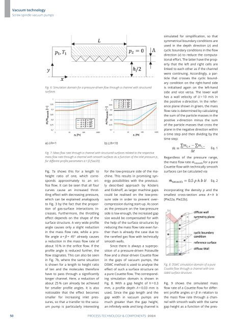
Fig. 6: Simulation domain for a pressure-driven flow through a channel with structured<br />
surfaces<br />
a) L/h=1 b) L/h=10<br />
Fig. 7: Mass flow rate through a channel with structured surfaces related to the respective<br />
mass flow rate through a channel with smooth surfaces as a function of the inlet pressure p 1<br />
for different profile parameters α = β [Saz20].<br />
Fig. 7a shows this for a length to<br />
height ratio of one, which corresponds<br />
approximately to an orifice<br />
flow. It can be seen that all four<br />
curves cause an increased throttling<br />
effect with decreasing pressure,<br />
which can be explained analogously<br />
to Fig. 3 by the fact that the proportion<br />
of gas-surface interactions increases.<br />
Furthermore, the throttling<br />
effect depends on the shape of the<br />
surface structure. A very wide profile<br />
angle causes only a slight reduction<br />
in the mass flow rate, while a profile<br />
angle α = β = 45° already causes<br />
a reduction in the mass flow rate of<br />
about 10 % in the orifice flow. If the<br />
profile angle is reduced further, the<br />
flow stagnates. This can also be seen<br />
in Fig. 7b, where the same situation<br />
is shown for a length to height ratio<br />
of ten and the molecules therefore<br />
have to pass through a significantly<br />
longer channel. Here, a reduction of<br />
about 25 % can already be achieved<br />
for smaller profile angles. It is also<br />
noticeable that the effect becomes<br />
smaller for increasing inlet pressures,<br />
so that a transfer to the vacuum<br />
pump is particularly interesting<br />
for the low-pressure side of the machine.<br />
This results in promising synergy<br />
possibilities with the previously<br />
described approach by Kösters<br />
and Eickhoff, as larger machine gaps<br />
could be realised on the low-pressure<br />
side in order to prevent overcompression<br />
during start-up. As soon<br />
as the pressure on the low-pressure<br />
side is low enough, the increased gap<br />
size would be compensated for with<br />
the help of the surface structures by<br />
reducing the mass flow rate even further<br />
than is already the case due to<br />
the rarefied gas flow with technically<br />
smooth walls.<br />
Since there is always a superposition<br />
of a pressure-driven Poiseuille<br />
flow and a shear-driven Couette flow<br />
in the gaps of vacuum pumps, the<br />
DSMC method is used to analyse the<br />
effect of such a surface structure on<br />
a pure Couette flow. The corresponding<br />
simulation domain is shown in<br />
Fig. 8. With a gap height of h = 0.3<br />
mm, a profile depth Λ = 0.03 mm is<br />
used. Since the gap length and the<br />
gap width in vacuum pumps are<br />
much greater than the gap height,<br />
an infinitely wide and long channel is<br />
simulated for simplification, so that<br />
symmetrical boundary conditions are<br />
used in the depth direction (z) and<br />
cyclic boundary conditions in the flow<br />
direction (x) to reduce the computational<br />
effort. The latter have the property<br />
that the left and right cells are<br />
linked to each other as if the channel<br />
were continuing. Accordingly, a particle<br />
that crosses the cyclic boundary<br />
condition on the right-hand side<br />
is initialised again on the left-hand<br />
side and vice versa. The lower wall<br />
has a wall velocity of U = 10 m/s in<br />
the positive x-direction. In the reference<br />
plane shown in green, the mass<br />
flow rate is determined by calculating<br />
the sum of the particle masses in the<br />
positive x-direction minus the sum<br />
of the particle masses that cross the<br />
plane in the negative direction within<br />
a time step and then dividing by the<br />
time step:<br />
Eq. 1<br />
Regardless of the pressure range,<br />
the mass flow rate<br />
for a pure<br />
Couette flow with technically smooth<br />
surfaces can be calculated via<br />
Eq. 2<br />
incorporating the density ρ and the<br />
smallest cross-section area A = h b<br />
[Ple22a, Ple22b].<br />
Fig. 8: DSMC simulation domain of a pure<br />
Couette flow through a channel with onesided<br />
surface structure.<br />
Fig. 9 shows the simulated mass<br />
flow rate of a Couette flow for different<br />
profile angles α = β in relation to<br />
the mass flow rate through a channel<br />
with smooth walls with the same<br />
gap height as a function of the pres-<br />
50 PROCESS TECHNOLOGY & COMPONENTS <strong>2024</strong>