PuK - Process Technology & Components 2024
A technical trade magazine with a history of more than 60 years.
A technical trade magazine with a history of more than 60 years.

You also want an ePaper? Increase the reach of your titles
YUMPU automatically turns print PDFs into web optimized ePapers that Google loves.
<strong>Components</strong><br />
Frequency converter<br />
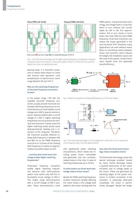
Fig. 3: The three-level technology plus the higher switching frequency compared to standard<br />
converters reduce the harmonic current parts (ripple current) to 10 % so that the converterbased<br />
rotor losses are significantly lower.<br />
PWM pattern. Using three-level technology,<br />
the voltage level is cut by half,<br />
which in turn reduces the current<br />
ripple by half in the first approximation.<br />
This in turn results in much<br />
lower rotor heat. With the same PWM<br />
frequency, three-level converters can<br />
reduce the losses generated in the<br />
rotor by about 75 %. Therefore, many<br />
applications can work without motor<br />
filters or smoothing chokes between<br />
motor and converter, which reduces<br />
the weight, the installation space and<br />
the costs of the system. Furthermore,<br />
users benefit from the optimized<br />
overall efficiency.<br />
bearing loads. It is therefore necessary<br />
to reduce these losses to a level<br />
that ensures safe operation. Limit<br />
temperatures of synchronous rotors<br />
range between 90 and 150 °C.<br />
Why are the switching frequencies<br />
of two-level frequency converters<br />
limited?<br />
In the power range >100 kW, the<br />
available two-level frequency converters<br />
usually provide maximum admissible<br />
switching frequencies of 4 or<br />
6 kHz because an intermediate circuit<br />
voltage up to 600 V requires semiconductor<br />
switches (IGBTs) with a cut-off<br />
voltage of 1,200 V. Higher switching<br />
frequencies are not practical for technical<br />
and economic reasons since the<br />
higher switching losses would cause<br />
disproportionate heating and a reduction<br />
of the ampacity. Therefore,<br />
the maximum possible effective rotating<br />
field frequency is between 600<br />
and 800 Hz as the PWM frequency<br />
must be 8 to 10 times of the rotating<br />
field frequency to realize an approximately<br />
sinusoidal output current.<br />
… and why does three-level technology<br />
enable higher switching<br />
frequencies?<br />
Three-level frequency converters<br />
enable higher switching frequencies<br />
because each semiconductor<br />
switch must switch only half the intermediate<br />
circuit voltage of 300 V.<br />
This makes using semiconductors<br />
with a cut-off voltage of 600 V possible.<br />
These semiconductors come<br />
Fig. 4: Influence of speed and rotating field frequency on the motor design<br />
Fig. 5: The three-level technology cuts the voltage level in half, which in turn reduces the<br />
current ripple by half in the first approximation<br />
with significantly better switching<br />
characteris tics, which makes the resulting<br />
power losses controllable<br />
and generates only low converterrelated<br />
losses in the rotor in spite of<br />
switching frequencies up to 32 kHz.<br />
To what extent can three-level technology<br />
reduce motor losses?<br />
Beside the PWM switching frequency,<br />
another important variable affecting<br />
the motor losses is the voltage level<br />
added to the motor winding with the<br />
How does the three-level technology<br />
reduce insulation stress?<br />
The three-level technology solves the<br />
‘partial discharge problem’ feared<br />
by many. Partial discharge means<br />
a gradual destruction of the stator<br />
insulation due to voltage peaks at<br />
the motor. These are generated by<br />
switching edges of the power transistors<br />
in modern converters. If the<br />
insulation is eventually destroyed<br />
completely, the motor is permanently<br />
damaged. Beside the length<br />
98 PROCESS TECHNOLOGY & COMPONENTS <strong>2024</strong>