ATW-7376 - Audio-Technica
ATW-7376 - Audio-Technica
ATW-7376 - Audio-Technica

You also want an ePaper? Increase the reach of your titles
YUMPU automatically turns print PDFs into web optimized ePapers that Google loves.
2<br />
Professional UHF Wireless Systems<br />
This device complies with part 15 of the FCC Rules. Operation is<br />
subject to the condition that this device does not cause harmful<br />
interference.<br />
This device complies with INDUSTRY CANADA R.S.S. 210, en<br />
conformité avec IC: RSS-210/CNR210. Operation is subject to<br />
the following conditions: 1) This device may not cause harmful<br />
interference and 2) this device must accept any interference<br />
received, including interference which may cause undesired<br />
operation.<br />
Individuals with implanted cardiac pacemakers or AICD<br />
devices: Please see notice on back cover.<br />
CAUTION! The circuits inside the receiver and transmitter have<br />
been precisely adjusted for optimum performance and<br />
compliance with federal regulations. Do not attempt to open the<br />
receiver or transmitter. To do so will void the warranty, and may<br />
cause improper operation.<br />
Introduction<br />
Thank you for choosing an <strong>Audio</strong>-<strong>Technica</strong> professional<br />
wireless system. You have joined thousands of other satisfied<br />
customers who have chosen our products because of their<br />
quality, performance and reliability. This <strong>Audio</strong>-<strong>Technica</strong><br />
wireless microphone system is the successful result of years<br />
of design and manufacturing experience.<br />
This professional wireless system provides a choice of 100<br />
PLL-synthesized UHF frequencies. Each system includes a<br />
receiver and either a body-pack or handheld transmitter.<br />
The receiver features true diversity reception. Two antennas<br />
feed two completely independent RF sections on the same<br />
frequency; automatic logic circuitry continuously compares<br />
and selects the superior received signal, providing better<br />
sound quality and reducing the possibility of interference and<br />
dropouts. The receiver is half-width for a standard 19" (1U)<br />
rack mount. Two receivers (on different frequencies) can be<br />
mounted side by side, using an AT8628 joining plate kit.<br />
The versatile <strong>ATW</strong>-T75 UniPak body-pack transmitter has<br />
both low- and high-impedance inputs plus a bias connection,<br />
for use with dynamic and electret condenser microphones, as<br />
well as Hi-Z instrument pickups. The <strong>ATW</strong>-T73 handheld condenser<br />
microphone/transmitter features the same element as<br />
the legendary AT4033 studio condenser microphone. The<br />
<strong>ATW</strong>-T76 handheld dynamic microphone/transmitter features<br />
a Hi-ENERGY ® neodymium dynamic element. The UniPak and<br />
handheld transmitters use internal 9-volt batteries and have<br />
Off/Standby/On switches and battery condition indicators.<br />
Please note that in multiple-system applications there must<br />
be a transmitter-receiver combination set to a separate<br />
frequency for each input desired (only one transmitter for each<br />
receiver). Because some of the wireless frequencies are in or<br />
near UHF TV frequencies, only certain wireless frequencies<br />
are useable in a particular geographic area. Also, only certain<br />
of the available operating frequencies may be used together.<br />
(Suggestions for multiple-system frequency grouping will be<br />
found on page 7.)<br />
Installation and Operation<br />
CAUTION<br />
RISK OF ELECTRIC SHOCK<br />
DO NOT OPEN<br />
Warning: To prevent fire or shock hazard, do<br />
not expose this appliance to rain or moisture.<br />
Attention: Pour prévenir feu ou choc<br />
électrique, ne pas exposé l’appareil à la pluie<br />
ou à l’humidité.<br />
AVIS<br />
RISQUE DE CHOC ÉLECTRIQUE<br />
NE PAS OUVRIR<br />
To prevent electric shock, do not remove the<br />
cover. There are no user-serviceable parts<br />
inside. Internal adjustments are for qualified<br />
professionals only. Refer all servicing to<br />
qualified service personnel.<br />
Pour prévenir un choc électrique, ne pas ouvrir<br />
le couvercle. Il n’y aucune pièces de rechanges<br />
à l’intérieur. Tout ajustement interne doit être<br />
fait par une personne qualifié seulement.<br />
Référez tout réparation au personnel qualifié.<br />
Receiver Installation<br />
Location<br />
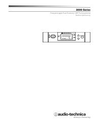
For best operation the receiver should be at least 3 ft. above<br />
the ground and at least 3 ft. away from a wall or metal surface<br />
to minimize reflections. The<br />
transmitter should be at<br />
least 3 ft. from the receiver,<br />
as shown in Figure A.<br />
Keep antennas away from<br />
noise sources such as digital<br />
equipment, motors,<br />
automobiles and neon<br />
lights, as well as large<br />
metal objects.<br />
Fig. A<br />
Output Connections<br />
There are two audio outputs on the back of the receiver:<br />
balanced (15.8 mV) and unbalanced (50 mV) . Use shielded<br />
audio cable for the connection between the receiver and the<br />
mixer. If the input of the mixer is a 1 ⁄4" jack, connect a cable<br />
from the 1 ⁄4" unbalanced audio output on the back of the<br />
receiver to the mixer. If the input of the mixer is an XLR-type<br />
input, connect a cable from the balanced XLR-type audio<br />
output on the back of the receiver to the mixer.<br />
The two isolated audio outputs permit simultaneous feeds<br />
to both unbalanced and balanced inputs. For example, both<br />
a guitar amp and a mixer can be driven by the receiver.<br />
Antennas<br />
Attach the antennas to the antenna input jacks. The antennas<br />
are normally positioned in the shape of a “V” (45° from<br />
vertical) for best reception.<br />
Power Connections<br />
Connect to a standard 120 volt 60 Hz AC power outlet. If<br />
there is no AC power available, the back panel is equipped<br />
with a jack for an external 12-18 volt DC source. The jack<br />
takes a standard 2.5 mm I.D. coaxial DC power plug, center<br />
negative. Power from the DC input jack is switched by the<br />
front-panel Power switch.