ATW-7376 - Audio-Technica
ATW-7376 - Audio-Technica
ATW-7376 - Audio-Technica

You also want an ePaper? Increase the reach of your titles
YUMPU automatically turns print PDFs into web optimized ePapers that Google loves.
7000 Series Professional<br />
UHF Wireless Systems<br />
<strong>ATW</strong>-7373 Handheld Condenser Microphone System<br />
<strong>ATW</strong>-7375 UniPak Transmitter System<br />
<strong>ATW</strong>-<strong>7376</strong> Handheld Dynamic Microphone System<br />
Installation and Operation
2<br />
Professional UHF Wireless Systems<br />
This device complies with part 15 of the FCC Rules. Operation is<br />
subject to the condition that this device does not cause harmful<br />
interference.<br />
This device complies with INDUSTRY CANADA R.S.S. 210, en<br />
conformité avec IC: RSS-210/CNR210. Operation is subject to<br />
the following conditions: 1) This device may not cause harmful<br />
interference and 2) this device must accept any interference<br />
received, including interference which may cause undesired<br />
operation.<br />
Individuals with implanted cardiac pacemakers or AICD<br />
devices: Please see notice on back cover.<br />
CAUTION! The circuits inside the receiver and transmitter have<br />
been precisely adjusted for optimum performance and<br />
compliance with federal regulations. Do not attempt to open the<br />
receiver or transmitter. To do so will void the warranty, and may<br />
cause improper operation.<br />
Introduction<br />
Thank you for choosing an <strong>Audio</strong>-<strong>Technica</strong> professional<br />
wireless system. You have joined thousands of other satisfied<br />
customers who have chosen our products because of their<br />
quality, performance and reliability. This <strong>Audio</strong>-<strong>Technica</strong><br />
wireless microphone system is the successful result of years<br />
of design and manufacturing experience.<br />
This professional wireless system provides a choice of 100<br />
PLL-synthesized UHF frequencies. Each system includes a<br />
receiver and either a body-pack or handheld transmitter.<br />
The receiver features true diversity reception. Two antennas<br />
feed two completely independent RF sections on the same<br />
frequency; automatic logic circuitry continuously compares<br />
and selects the superior received signal, providing better<br />
sound quality and reducing the possibility of interference and<br />
dropouts. The receiver is half-width for a standard 19" (1U)<br />
rack mount. Two receivers (on different frequencies) can be<br />
mounted side by side, using an AT8628 joining plate kit.<br />
The versatile <strong>ATW</strong>-T75 UniPak body-pack transmitter has<br />
both low- and high-impedance inputs plus a bias connection,<br />
for use with dynamic and electret condenser microphones, as<br />
well as Hi-Z instrument pickups. The <strong>ATW</strong>-T73 handheld condenser<br />
microphone/transmitter features the same element as<br />
the legendary AT4033 studio condenser microphone. The<br />
<strong>ATW</strong>-T76 handheld dynamic microphone/transmitter features<br />
a Hi-ENERGY ® neodymium dynamic element. The UniPak and<br />
handheld transmitters use internal 9-volt batteries and have<br />
Off/Standby/On switches and battery condition indicators.<br />
Please note that in multiple-system applications there must<br />
be a transmitter-receiver combination set to a separate<br />
frequency for each input desired (only one transmitter for each<br />
receiver). Because some of the wireless frequencies are in or<br />
near UHF TV frequencies, only certain wireless frequencies<br />
are useable in a particular geographic area. Also, only certain<br />
of the available operating frequencies may be used together.<br />
(Suggestions for multiple-system frequency grouping will be<br />
found on page 7.)<br />
Installation and Operation<br />
CAUTION<br />
RISK OF ELECTRIC SHOCK<br />
DO NOT OPEN<br />
Warning: To prevent fire or shock hazard, do<br />
not expose this appliance to rain or moisture.<br />
Attention: Pour prévenir feu ou choc<br />
électrique, ne pas exposé l’appareil à la pluie<br />
ou à l’humidité.<br />
AVIS<br />
RISQUE DE CHOC ÉLECTRIQUE<br />
NE PAS OUVRIR<br />
To prevent electric shock, do not remove the<br />
cover. There are no user-serviceable parts<br />
inside. Internal adjustments are for qualified<br />
professionals only. Refer all servicing to<br />
qualified service personnel.<br />
Pour prévenir un choc électrique, ne pas ouvrir<br />
le couvercle. Il n’y aucune pièces de rechanges<br />
à l’intérieur. Tout ajustement interne doit être<br />
fait par une personne qualifié seulement.<br />
Référez tout réparation au personnel qualifié.<br />
Receiver Installation<br />
Location<br />
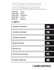
For best operation the receiver should be at least 3 ft. above<br />
the ground and at least 3 ft. away from a wall or metal surface<br />
to minimize reflections. The<br />
transmitter should be at<br />
least 3 ft. from the receiver,<br />
as shown in Figure A.<br />
Keep antennas away from<br />
noise sources such as digital<br />
equipment, motors,<br />
automobiles and neon<br />
lights, as well as large<br />
metal objects.<br />
Fig. A<br />
Output Connections<br />
There are two audio outputs on the back of the receiver:<br />
balanced (15.8 mV) and unbalanced (50 mV) . Use shielded<br />
audio cable for the connection between the receiver and the<br />
mixer. If the input of the mixer is a 1 ⁄4" jack, connect a cable<br />
from the 1 ⁄4" unbalanced audio output on the back of the<br />
receiver to the mixer. If the input of the mixer is an XLR-type<br />
input, connect a cable from the balanced XLR-type audio<br />
output on the back of the receiver to the mixer.<br />
The two isolated audio outputs permit simultaneous feeds<br />
to both unbalanced and balanced inputs. For example, both<br />
a guitar amp and a mixer can be driven by the receiver.<br />
Antennas<br />
Attach the antennas to the antenna input jacks. The antennas<br />
are normally positioned in the shape of a “V” (45° from<br />
vertical) for best reception.<br />
Power Connections<br />
Connect to a standard 120 volt 60 Hz AC power outlet. If<br />
there is no AC power available, the back panel is equipped<br />
with a jack for an external 12-18 volt DC source. The jack<br />
takes a standard 2.5 mm I.D. coaxial DC power plug, center<br />
negative. Power from the DC input jack is switched by the<br />
front-panel Power switch.
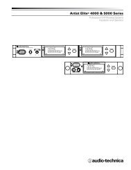
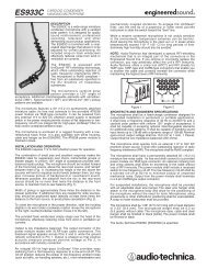
Fig. B Receiver Front Panel<br />
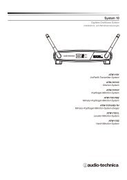
Fig. C Receiver Rear Panel<br />
Receiver Controls And Functions<br />
10 1 2 3 4 5 6 7 8 9<br />
10<br />
Front Panel Controls and Functions (Fig. B)<br />
1 POWER SWITCH/INDICATOR: Press switch on, and<br />
the “power” indicator will light.<br />
2 CHANNEL NUMBER DISPLAY: Indicates the current<br />
channel setting.<br />
3 X10 CHANNEL SELECTOR SWITCH: Selects the number<br />
shown in the left column of the Channel Number Display.<br />
4 X1 CHANNEL SELECTOR SWITCH: Selects the number<br />
shown in the right column of the Channel Number<br />
Display.<br />
5 CHANNEL SET BUTTON: Press this button to input the<br />
channel shown in the Channel Number Display.<br />
6 RF SIGNAL LEVEL INDICATOR: Indicates the<br />
strength of the RF signal received from the transmitter.<br />
The LEDs will light up from left to right.<br />
7 AF LEVEL INDICATOR: Indicates the audio modulation<br />
level of the received signal. (Not affected by the<br />
setting of the AF Level control.)<br />
8 TUNER OPERATION INDICATOR: Indicates which<br />
tuner has the better reception and is in operation.<br />
9 AF LEVEL CONTROL: Adjusts the level at both audio<br />
output jacks.<br />
10 MOUNTING ADAPTERS: For mounting the receiver<br />
in any standard 19" rack. Attach to receiver with<br />
screws supplied. (Use optional AT8628 joining plate<br />
kit to mount two receivers side-by-side.)<br />
11 12 13 14 15 16 17 18<br />
Rear Panel Controls and Functions (Fig. C)<br />
11 TUNER “B” ANTENNA JACK: Antenna connector for<br />
tuner “B.” Attach the antenna directly, or extend it<br />
with an antenna cable.<br />
12 SQUELCH CONTROL: Adjusts level of noise-muting<br />
circuit (preset at factory but can be adjusted as<br />
circumstances warrant).<br />
13 BALANCED AUDIO OUTPUT JACK: XLRM-type connector.<br />
A standard 2-conductor shielded cable can be used<br />
to connect the receiver output to a balanced microphone<br />
level input on a mixer.<br />
14 GROUND LIFT SWITCH: Disconnects the ground pin<br />
of the balanced output (13) from ground. Normally, the<br />
switch should be to the left (ground connected). If hum<br />
caused by a ground loop occurs, slide switch to the right.<br />
15 UNBALANCED AUDIO OUTPUT JACK: 1 ⁄4" phone jack.<br />
Can be connected to an unbalanced aux-level input of a<br />
mixer or tape recorder.<br />
16 DC POWER INPUT: For an external 12-18V DC source<br />
(requires 350 mA). Center pin of jack is negative.<br />
17 AC POWER: Power cord for 120V AC power input.<br />
18 TUNER “A” ANTENNA JACK: Antenna connector for<br />
tuner “A.” Attach the antenna directly, or extend it<br />
with an antenna cable.<br />
3
4<br />
Battery Selection<br />
An alkaline 9-volt battery is recommended.<br />
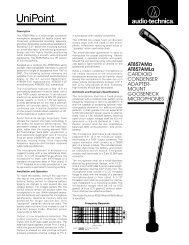
UniPak Transmitter Battery Installation<br />
1. Slide off the battery cover as shown in Figure D.<br />
2. Carefully insert a fresh 9V alkaline battery, observing<br />
correct polarity as marked inside the battery compartment.<br />
The transmitter housing is designed to prevent incorrect<br />
installation of the battery. Do not force the battery in.<br />
3. Replace the battery cover.<br />
Handheld Transmitter Battery Installation<br />
1. While holding the upper part of the transmitter body just<br />
below the ball-screen, unscrew the lower body cover and<br />
slide it downward to expose the battery compartment.<br />
2. Lift the white “battery keeper” arm, and insert a 9V alkaline<br />
battery. Be certain to observe correct polarity as marked<br />
inside the battery compartment (Fig. E). The transmitter<br />
housing is designed to prevent incorrect installation of the<br />
battery.<br />
Do not force the battery in.<br />
3. Replace the lower body cover. Do not overtighten.<br />
Fig. E<br />
Fig. F<br />
Fig. D<br />
Channel<br />
Selectors<br />
Screwdriver<br />
Battery Polarity<br />
Diagram<br />
Channel<br />
Selectors<br />
Guitar<br />
Trimmer (GT)<br />
Microphone<br />
Trimmer (MT)<br />
Transmitter Setup<br />
Battery Condition Indicator<br />
After the battery is installed, turn the power on. The battery<br />
condition indicator LED (Fig. G/H) should flash momentarily.<br />
If it does not, the battery is installed incorrectly or it is dead.<br />
If the indicator LED stays on (does not flash), the battery<br />
voltage is low and the battery should be replaced. If this<br />
happens during use, replace the battery immediately to<br />
ensure continued operation.<br />
Input<br />
Connector<br />
Power Switch<br />
(Off/Standby/On)<br />
Battery Condition<br />
Indicator<br />
Antenna<br />
Fig. G Fig. H<br />
Battery<br />
Condition<br />
Indicator<br />
Power Switch<br />
(Off/Standby/On)<br />
UniPak Transmitter Input Connection<br />
Connect an audio input device (microphone or guitar cable)<br />
to the audio input connector on the bottom of the transmitter.<br />
A number of <strong>Audio</strong>-<strong>Technica</strong> professional microphones and<br />
cables are available separately, pre-terminated with a UniPak<br />
input connector (see “Optional System Accessories” on page 6).<br />
UniPak Transmitter Antenna<br />
The UniPak transmitter includes a permanently-attached flexible<br />
antenna. For best results, allow the antenna to hang freely and<br />
full length from the bottom of the transmitter. If the received<br />
signal is marginal, experiment with different transmitter positions<br />
on your body or instrument; or try repositioning the receiver.<br />
Do not attempt to remove, replace or change the length<br />
of the transmitting antenna.<br />
<strong>ATW</strong>-T73 Handheld Transmitter Pad<br />
The <strong>ATW</strong>-T73 offers a pad switch which increases the maximum<br />
SPL capability of the microphone by 6 dB. The switch is located<br />
under the wire-mesh grille near the base of the element.<br />
Handheld Transmitter Switch Cover<br />
The handheld systems include two switch cover labels that fit<br />
into the grooved recess on the bottom of the transmitter’s lower<br />
body cover. The switch cover label may be used to limit access<br />
to the power switch, or to hide the switch and battery condition<br />
indicator from view.
Turn down the AF Level of the receiver as well as the mixer.<br />
Switch on the receiver. Do not switch on the transmitter yet.<br />
Receiver On…<br />
The power indicator will light up and one of the tuner operation<br />
indicator LEDs (A or B) will light, even though the transmitter is<br />
not on. If any of the RF LEDs light up at this point, there may be<br />
RF interference in the area. If this occurs, select another frequency<br />
using the front-panel channel selectors. The channel display<br />
numbers will begin to flash alternately while changing channels.<br />
Once the desired numbers are displayed, press the “Set”<br />
button to engage the channel.<br />
Transmitter On…<br />
Before turning on the transmitter, use the provided screwdriver<br />
to set the transmitter channel selector switches (Fig. D/F) to the<br />
same numbers as those displayed on the receiver. The transmitter<br />
channel selector switch marked “X10” corresponds to the<br />
receiver‘s left-column channel display number, and the selector<br />
switch marked “X1” corresponds to the receiver‘s right-column<br />
channel display number. Always turn the transmitter off when<br />
changing frequencies.<br />
When the transmitter is switched on and in normal operation,<br />
the receiver’s RF signal level indicators will light up from left to<br />
right. For optimum performance at least four, and preferably five,<br />
of the signal strength indicators should light up when the transmitter<br />
is switched on. The transmitters have a three-position<br />
power switch. When the switch is set to “Standby,” the transmitter<br />
produces RF with no audio signal. When the switch is<br />
“On,” the transmitter produces both RF and audio.<br />
Setting Levels<br />
Correct adjustment of transmitter audio input, receiver audio output,<br />
and mixer/amplifier input and output levels is important for<br />
optimum system performance.<br />
• <strong>ATW</strong>-T73 and <strong>ATW</strong>-T76 Handheld Transmitters<br />
The 7000 Series handheld transmitters have factory pre-set<br />
audio input levels.<br />
1. Set the receiver’s AF Level control to “0.”<br />
2. Turn the transmitter on and power up the system.<br />
3. Turn down the mixer’s input trim control (if provided) on<br />
the selected channel; make an initial adjustment of the mixer<br />
channel and output level controls that will allow audio through<br />
the system.<br />
4. While speaking/singing into the microphone at typically-loud<br />
levels, adjust the mixer’s input trim control so the highest sound<br />
pressure level going into the microphone causes no input overload<br />
in the mixer, and yet permits the mixer’s level controls to<br />
operate in their “normal” range (not set too high or too low).<br />
NOTE: With the receiver’s AF Level set at “0,” its balanced output<br />
voltage will be similar to that of a typical wired microphone.<br />
However, the AF Level may need to be adjusted to accommodate<br />
some microphone inputs.<br />
• <strong>ATW</strong>-T75 UniPak Transmitter<br />
Trimmer adjustments in the UniPak transmitter (Fig. D) will<br />
enable you to use microphones or instruments with different<br />
output levels.<br />
1. Set both the transmitter Mic Level (MT) and Guitar Level (GT)<br />
controls to their full counter-clockwise position (minimum). (The<br />
level control not being used should be set to minimum.)<br />
2. Set the receiver’s AF Level control to “0.”<br />
3. Plug the mic or instrument into the transmitter and power up<br />
the system.<br />
4. For MIC: Make an initial adjustment of the mixer’s level<br />
controls that will allow audio through the system as you increase<br />
the transmitter’s Mic Level.<br />
System Operation<br />
For INSTRUMENT: Make an initial adjustment of the instrument<br />
amplifier input level control that will allow audio through<br />
the system as you increase the transmitter’s Guitar Level.<br />
5. For MIC: While speaking/singing into the microphone at typically-loud<br />
levels, turn up the transmitter’s Mic Level (MT) control<br />
until the maximum audio output of the mic lights about three or<br />
four green LED segments on the receiver’s AF Level indicator.<br />
For INSTRUMENT: While playing the instrument at typicallyloud<br />
levels, turn up the transmitter’s Guitar Level (GT) control<br />
until the maximum audio output of the instrument lights about<br />
three or four green LED segments on the receiver’s AF Level<br />
indicator.<br />
NOTE: Do not set the transmitter level too high (as indicated<br />
by lighting of the red LED) – doing so will cause the system to<br />
overload and distort.<br />
6. For MIC: Next, while again speaking/singing into the<br />
microphone at typically-loud levels, adjust the mixer’s input trim<br />
control so the highest sound pressure level going into the microphone<br />
causes no input overload in the mixer, and yet permits<br />
the mixer’s channel and output level controls to operate in their<br />
“normal” range (not set too high or too low).<br />
NOTE: With the receiver’s AF Level control set at “0,” the<br />
balanced output voltage will be similar to that of a typical wired<br />
microphone. However, the AF Level control may be adjusted<br />
to accommodate some microphone inputs – for example, those<br />
with limited-range or no input trim controls.<br />
For INSTRUMENT: Next, while again playing the instrument<br />
at typically-loud levels, adjust the receiver’s AF Level control so<br />
the highest signal level causes no input overload in the instrument<br />
amplifier, and yet permits the amplifier’s input level<br />
controls to operate in their “normal” range (not set too high<br />
or too low).<br />
NOTE: With some instrument amplifiers, the receiver’s AF Level<br />
control may need to be adjusted to between “0” and “+6” to<br />
better drive the amplifier.<br />
CAUTION! The small trimmer controls are delicate; use only a<br />
small screwdriver or alignment tool with a maximum 3 /32"-wide<br />
blade. Do not force the trimmers beyond their normal 260°<br />
range of rotation.<br />
Receiver Squelch<br />
The squelch control on the back panel of the receiver is preset<br />
at the factory, but can be adjusted if you must use the system<br />
in an area with considerable RF interference. If there is<br />
interference in the audio, and changing the channel is not an<br />
option, adjust the squelch control so the system will receive the<br />
signal from your transmitter but will “squelch” or eliminate the<br />
unwanted background RF noise. This adjustment can cause a<br />
reduction in useable range of the wireless transmitter, so set the<br />
control to the lowest position that reliably mutes the unwanted<br />
RF signals.<br />
RF Interference<br />
Please note that wireless frequencies are shared with<br />
other radio services. According to Federal Communications<br />
Commission regulations, “Wireless microphone operations<br />
are unprotected from interference from other licensed<br />
operations in the band. If any interference is received by<br />
any Government or non-Government operation, the wireless<br />
microphone must cease operation...”<br />
If you need assistance with operation or frequency selection,<br />
please contact your dealer or the <strong>Audio</strong>-<strong>Technica</strong> professional<br />
division. Extensive wireless information also is available on the<br />
<strong>Audio</strong>-<strong>Technica</strong> Web site at www.audio-technica.com.<br />
5
6<br />
Specifications † Optional System Accessories<br />
OVERALL SYSTEM<br />
Operating Frequency UHF band, 728.125 to 740.500 MHz<br />
Number of Channels 100 total<br />
Frequency Stability ±0.005%, Phase Lock Loop<br />
frequency control<br />
Modulation Mode FM<br />
Normal Deviation ±10 kHz<br />
Operating Range 300' typical<br />
Operating Temperature Range 41°F (5° C) to 113° F (45° C)<br />
Frequency Response 100 Hz to 15 kHz<br />
RECEIVER<br />
Receiving System Dual independent receivers, automatic<br />
switching diversity<br />
Image Rejection 50 dB nominal, 45 dB minimum<br />
Signal-to-noise Ratio 110 dB at 30 kHz deviation<br />
(IEC-weighted), maximum modulation<br />
75 kHz<br />
Total Harmonic Distortion ≤1% (10 kHz deviation at 1 kHz)<br />
Sensitivity 26 dBµV (S/N 60 dB at 5 kHz deviation,<br />
IEC-weighted)<br />
Intermediate Frequency 45 MHz, 10.7 MHz<br />
<strong>Audio</strong> Output (AF Level set at“0”)<br />
Unbalanced: 50 mV (at 1 kHz, ±5 kHz deviation,<br />
10k ohm load)<br />
Balanced: 15.8 mV (at 1 kHz, ±5 kHz deviation,<br />
10k ohm load)<br />
Output Connectors Unbalanced: 1 /4" phone jack<br />
Balanced: XLRM-type<br />
Power Supply 120V AC 60 Hz; or 12-18V DC,<br />
350 mA, with external supply<br />
Dimensions 8.27" (210.0 mm) W x 1.93" (49.0 mm) H<br />
x 8.86" (225.0 mm) D<br />
Weight 3.9 lbs (1.8 kgs)<br />
Accessories Included Two flexible UHF antennas, rack-mount<br />
adapters<br />
UNIPAK TRANSMITTER<br />
RF Power Output 50 mW Max<br />
Spurious Emissions Under federal regulations<br />
Input Connections High impedance, low impedance, bias<br />
Battery 9V (NEDA type 1604) alkaline, not included<br />
Current Consumption 50 mA typical<br />
Battery Life Approximately 8-10 hours (depending on<br />
battery type and use pattern)<br />
Dimensions 2.44" (62.0 mm) W x 3.35" (85.0 mm) H<br />
x 1.02" (26.0 mm) D<br />
Net Weight (without battery) 2.8 oz (80 grams)<br />
HANDHELD TRANSMITTERS<br />
RF Power Output 50 mW Max<br />
Spurious Emissions Under federal regulations<br />
Microphone Element<br />
<strong>ATW</strong>-T73 A-T condenser, unidirectional<br />
<strong>ATW</strong>-T76 A-T Hi-ENERGY ® dynamic, unidirectional<br />
Battery 9V (NEDA type 1604) alkaline, not included<br />
Current Consumption<br />
<strong>ATW</strong>-T73 55 mA typical<br />
<strong>ATW</strong>-T76 50 mA typical<br />
Battery Life Approximately 8 hours (depending on<br />
battery type and use pattern)<br />
Dimensions<br />
<strong>ATW</strong>-T73 9.63" (244.5 mm) long<br />
<strong>ATW</strong>-T76 9.17" (233.0 mm) long<br />
Both 1.49" (37.9 mm) body diameter<br />
Net Weight (without battery)<br />
<strong>ATW</strong>-T73 12.2 oz (345 grams)<br />
<strong>ATW</strong>-T76 8.5 oz (240 grams)<br />
Accessories Included Stand clamp, switch cover labels<br />
MICROPHONES AND CABLES<br />
AT829cW AT829 miniature cardioid condenser microphone only,<br />
terminated for use with UniPak transmitter. Includes<br />
clothing clip and windscreen.<br />
MT830cW MT830R subminiature omnidirectional condenser<br />
microphone only, terminated for use with UniPak<br />
transmitter. Includes clothing clip and windscreen.<br />
MT830cW-TH ”Theater“ model, same as MT830cW except beige color<br />
mic and cable for concealment.<br />
AT831cW AT831b miniature cardioid condenser microphone only,<br />
terminated for use with UniPak transmitter. Includes<br />
clothing clip and windscreen.<br />
AT851cW AT851a surface-mount wide-range hemi-cardioid<br />
condenser microphone only, terminated for use with<br />
UniPak transmitter.<br />
AT857AMLcW AT857AMLa 19" gooseneck cardioid condenser<br />
microphone only, terminated for use with UniPak<br />
transmitter. Mounts to 5 /8"-27 thread. Includes windscreen.<br />
AT889cW Headworn noise-canceling condenser microphone only,<br />
terminated for use with UniPak transmitter. Includes<br />
windscreen and cable clip.<br />
ATM35cW ATM35 high-intensity miniature cardioid condenser<br />
microphone only, terminated for use with UniPak<br />
transmitter. Includes AT8418clip-on instrument mount.<br />
ATM73cW ATM73a headworn cardioid condenser microphone only,<br />
terminated for use with UniPak transmitter.<br />
ATM75cW ATM75 headworn cardioid condenser microphone only,<br />
terminated for use with UniPak transmitter. Includes<br />
windscreens and cable clip.<br />
PRO8HEcW PRO8HEx headworn hypercardioid dynamic microphone,<br />
terminated for use with UniPak transmitter. Includes<br />
windscreen and cable clip.<br />
PRO35xcW PRO35x cardioid condenser microphone only, terminated<br />
for use with UniPak transmitter. Includes AT8418clip-on<br />
instrument mount.<br />
AT-GCW Hi-Z instrument/guitar cable with 1 /4" phone plug,<br />
terminated for use with UniPak transmitter.<br />
XLRW Connecting cable for UniPak transmitter with an XLRF-type<br />
input connector, for Lo-Z microphones with XLRM-type<br />
output terminations.<br />
TRANSMITTER ACCESSORIES<br />
<strong>ATW</strong>-VP10 Vinyl pouch with belt clip to hold UniPak transmitter.<br />
AT8114 Foam windscreen for handheld transmitter.<br />
AT8141 Water-resistant pouch for UniPak transmitter.<br />
AT8456 Stand clamp for handheld transmitter, 5 /8"-27 threads.<br />
AT8431 Stand clamp for handheld transmitter, 5 /8"-27 threads.<br />
RECEIVER ACCESSORIES<br />
AT8628 Mounting plate adapter allows rack-mounting two<br />
<strong>ATW</strong>-R73 receivers side-by-side in a single 19" rack space.<br />
<strong>ATW</strong>-A20 Pair of UHF ground-plane antennas with 5 /8"-27 thread for<br />
mounting to microphone stands, etc. Takes RF cables with<br />
BNC connectors, not included.<br />
<strong>ATW</strong>-D70 UHF (728-750 MHz) active unity-gain antenna distribution<br />
system provides two “1-in, 4-out” RF channels; connects<br />
a pair of antennas to as many as four diversity receivers.<br />
Includes four DC interconnect cables to power up to four<br />
receivers, eight RF output cables and two rack-mount<br />
adapters. Mounts in a single 19" rack space. Requires<br />
<strong>ATW</strong>-RDCP cables for use with <strong>ATW</strong>-R73 receivers<br />
(available separately).<br />
<strong>ATW</strong>-RA1 Rack-mount antenna kit brings antenna inputs to the front<br />
of receiver for ease of setup, or when receiver is enclosed<br />
in a metal rack. Includes a pair of extendible antennas.<br />
NOTE: Two adapter kits are required when mounting<br />
two receivers side-by-side in a single 19" rack space.<br />
<strong>ATW</strong>-RDCP Polarity-inverting DC interconnect cables (set of four) for<br />
use in conjunction with <strong>ATW</strong>-R73 (or like-powered)<br />
receivers.<br />
†In the interest of standards development, A.T.U.S. offers full details on its test methods<br />
to other industry professionals on request.
Multi-channel Systems<br />
<strong>Audio</strong>-<strong>Technica</strong> 7000 Series UHF Wireless Operating Frequencies<br />
Designator Frequency (MHz) TV Channel<br />
00 728.125 57<br />
01 728.250 57<br />
02 728.375 57<br />
03 728.500 57<br />
04 728.625 57<br />
05 728.750 57<br />
06 728.875 57<br />
07 729.000 57<br />
08 729.125 57<br />
09 729.250 57<br />
10 729.375 57<br />
11 729.500 57<br />
12 729.625 57<br />
13 729.750 57<br />
14 729.875 57<br />
15 730.000 57<br />
16 730.125 57<br />
17 730.250 57<br />
18 730.375 57<br />
19 730.500 57<br />
20 730.625 57<br />
21 730.750 57<br />
22 730.875 57<br />
23 731.000 57<br />
24 731.125 57<br />
25 731.250 57<br />
26 731.375 57<br />
27 731.500 57<br />
28 731.625 57<br />
29 731.750 57<br />
30 731.875 57<br />
31 732.000 57<br />
32 732.125 57<br />
33 732.250 57<br />
34 732.375 57<br />
35 732.500 57<br />
36 732.625 57<br />
37 732.750 57<br />
38 732.875 57<br />
39 733.000 57<br />
40 733.125 57<br />
41 733.250 57<br />
42 733.375 57<br />
43 733.500 57<br />
44 733.625 57<br />
45 733.750 57<br />
46 733.875 57<br />
47 734.000 58<br />
48 734.125 58<br />
49 734.250 58<br />
7000 Series Frequency and Channel Designator List<br />
Following are groupings of frequencies suggested for multi-channel wireless systems.<br />
Group A: Channels 00, 02, 08, 15, 46, 50, 60 (or 62), 71, 76, 80, 93, 99 -or-<br />
Group B: Channels 01, 03, 07, 25, 30, 41, 44, 56, 69, 76, 77, 86<br />
For use where TV Channel 57 is operating:<br />
Channels 50, 60 (or 62), 71, 76, 80, 93, 99 (from Group A) -or-<br />
Channels 56, 69, 76, 77, 86 (from Group B)<br />
For use where TV Channel 58 is operating:<br />
Channels 00, 02, 08, 15, 46, 99 (from Group A) -or-<br />
Channels 01, 03, 07, 25, 30, 41, 44 (from Group B)<br />
For use where TV Channel 59 is operating:<br />
Channels 00, 02, 08, 15, 46, 50, 60 (or 62), 71, 76, 80, 93 (from Group A) -or-<br />
Channels 01, 03, 07, 25, 30, 41, 44, 56, 69, 76, 77, 86 (All of Group B)<br />
Designator Frequency (MHz) TV Channel<br />
50 734.375 58<br />
51 734.500 58<br />
52 734.625 58<br />
53 734.750 58<br />
54 734.875 58<br />
55 735.000 58<br />
56 735.125 58<br />
57 735.250 58<br />
58 735.375 58<br />
59 735.500 58<br />
60 735.625 58<br />
61 735.750 58<br />
62 735.875 58<br />
63 736.000 58<br />
64 736.125 58<br />
65 736.250 58<br />
66 736.375 58<br />
67 736.500 58<br />
68 736.625 58<br />
69 736.750 58<br />
70 736.875 58<br />
71 737.000 58<br />
72 737.125 58<br />
73 737.250 58<br />
74 737.375 58<br />
75 737.500 58<br />
76 737.625 58<br />
77 737.750 58<br />
78 737.875 58<br />
79 738.000 58<br />
80 738.125 58<br />
81 738.250 58<br />
82 738.375 58<br />
83 738.500 58<br />
84 738.625 58<br />
85 738.750 58<br />
86 738.875 58<br />
87 739.000 58<br />
88 739.125 58<br />
89 739.250 58<br />
90 739.375 58<br />
91 739.500 58<br />
92 739.625 58<br />
93 739.750 58<br />
94 739.875 58<br />
95 740.000 59<br />
96 740.125 59<br />
97 740.250 59<br />
98 740.375 59<br />
99 740.500 59<br />
7
1. Use only fresh alkaline batteries. Do not use “general<br />
purpose” (carbon-zinc) batteries.<br />
2. Position the receiver so that it has the fewest possible<br />
obstructions between it and the normal location of the<br />
transmitter. Line-of-sight is best.<br />
3. The transmitter and the receiver should be as close<br />
together as conveniently possible, but no closer together<br />
than three feet.<br />
4. The receiver antennas should be in the open and away from<br />
any metal. If mounted in a rack, have the unit on top, or use<br />
an <strong>ATW</strong>-RA1 kit to front-mount the antennas.<br />
5. The transmitter and receiver must be set to the same<br />
channel number.<br />
6. A receiver cannot receive signals from two transmitters at<br />
the same time.<br />
7. The power switch on the transmitter has three positions:<br />
“Off,” “Standby” and “On.” In the middle “Standby”<br />
position, the transmitter sends only RF to the receiver;<br />
the audio source is turned off.<br />
For future reference, please record your system information here (the serial numbers appear inside the battery compartment<br />
of each transmitter, and on the bottom of each receiver):<br />
Receiver <strong>ATW</strong>-R73 Serial Number<br />
Transmitter <strong>ATW</strong>-T73 Serial Number<br />
<strong>ATW</strong>-T75 Serial Number<br />
<strong>ATW</strong>-T76 Serial Number<br />
Notice to individuals with implanted cardiac pacemakers or AICD devices:<br />
Any source of RF (radio frequency) energy may interfere with normal functioning of the implanted device. All wireless<br />
microphones have low-power transmitters (less than 0.05 watts output) which are unlikely to cause difficulty,<br />
especially if they are at least a few inches away. However, since a “body-pack” mic transmitter typically is placed<br />
against the body, we suggest attaching it at the belt, rather than in a shirt pocket where it may be immediately adjacent<br />
to the medical device. Note also that any medical-device disruption will cease when the RF transmitting source<br />
is turned off. Please contact your physician or medical-device provider if you have any questions, or experience any<br />
problems with the use of this or any other RF equipment.<br />
One-Year Limited Warranty<br />
<strong>Audio</strong>-<strong>Technica</strong> professional wireless systems purchased in the U.S.A. are warranted for one year from date of purchase by <strong>Audio</strong>-<strong>Technica</strong> U.S., Inc.<br />
(A.T.U.S.) to be free of defects in materials and workmanship. In event of such defect, product will be repaired promptly without charge or, at our<br />
option, replaced with a new product of equal or superior value if delivered to A.T.U.S. or an Authorized Service Center, prepaid, together with the<br />
sales slip or other proof of purchase date. Prior approval from A.T.U.S. is required for return. This warranty excludes defects due to normal wear,<br />
abuse, shipping damage, or failure to use product in accordance with the instructions. This warranty is void in the event of unauthorized repair or<br />
modification, or removal or defacing of the product labeling.<br />
For return approval and shipping information, contact the Service Dept., <strong>Audio</strong>-<strong>Technica</strong> U.S., Inc., 1221 Commerce Drive, Stow, Ohio 44224.<br />
Except to the extent precluded by applicable state law, A.T.U.S. will have no liability for any consequential, incidental, or special damages; any<br />
warranty of merchantability or fitness for particular purpose expires when this warranty expires.<br />
This warranty gives you specific legal rights, and you may have other rights which vary from state to state.<br />
Outside the U.S.A., please contact your local dealer for warranty details.<br />
Twelve Tips To Obtain The Best Results<br />
<strong>Audio</strong>-<strong>Technica</strong> U.S., Inc., 1221 Commerce Drive, Stow, Ohio 44224 330/686-2600 www.audio-technica.com<br />
P51101-01-B/W ©2000 <strong>Audio</strong>-<strong>Technica</strong> U.S., Inc. Printed in Japan<br />
8. For best operation, all the RF Level LEDs should be lit<br />
(maximize RF input); but only the first two or three AF Level<br />
LEDs should be lit (don’t overmodulate).<br />
9. If the AF Level control of the receiver is set too high, it may<br />
over-drive the input of the mixer or clip the output of the<br />
receiver, causing distortion. Conversely, if the receiver output is<br />
set too low, the overall signal-to-noise ratio of the system may<br />
be reduced.<br />
10. You need to change channels 1) when a strong interference<br />
signal is received, 2) when the channel breaks down, or<br />
3) during multiple-system operation in order to select an<br />
interference-free channel.<br />
11. In the UniPak transmitter, the “MT” or “GT” input control not<br />
in use should be set to minimum.<br />
12. Turn the transmitter off when not in use. Remove the battery<br />
if the transmitter is not to be used for a period of time.