Compressed Air Treatment Products - Elion
Compressed Air Treatment Products - Elion
Compressed Air Treatment Products - Elion

Create successful ePaper yourself
Turn your PDF publications into a flip-book with our unique Google optimized e-Paper software.
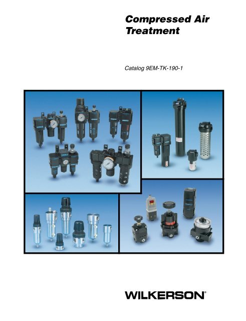
<strong>Compressed</strong> <strong>Air</strong><br />
<strong>Treatment</strong><br />
Catalog 9EM-TK-190-1
First incorporated in August of<br />
1948, Wilkerson manufactures a<br />
complete line of compressed air<br />
treatment and control products to<br />
meet a wide variety of industrial,<br />
process, consumer and health<br />
care applications. Today, Wilkerson<br />
serves over 500 different industries<br />
throughout the world.<br />
Over the years, Wilkerson facilities,<br />
manufacturing and engineering<br />
technology have kept pace with<br />
increased sales volume, the growing<br />
need to satisfy customers’ specific<br />
requirements and the demands<br />
placed on production.<br />
Wilkerson’s growing leadership in<br />
the industry is due to our determined<br />
commitment to quality; quality of<br />
products, services and people.<br />
Our dedication to the total quality<br />
management process assures our<br />
customers that we can consistently<br />
provide the highest levels of product<br />
quality and customer service<br />
required to meet their needs.<br />
From the very beginning, Wilkerson<br />
has sold its products through a<br />
world-wide, independent distributor<br />
network. We currently have 200<br />
distributors throughout North<br />
America, plus an expanding network<br />
of international distributors in over<br />
40 countries. Our distributors, who<br />
have many years of experience<br />
in compressed air treatment and<br />
control, offer excellent product<br />
knowledge, technical assistance<br />
WARNING<br />
and local inventory. As a result of<br />
representing other complimentary<br />
products, they are able to satisfy<br />
their customers’ total requirements.<br />
Today’s broad line of Wilkerson<br />
products is the result of<br />
continuing product innovations<br />
and technology advancements<br />
which frequently become industry<br />
standards. Wilkerson is dedicated<br />
to designing and manufacturing<br />
innovative products with features<br />
and operating characteristics that<br />
meet customer requirements for<br />
quality, performance, reliability,<br />
serviceability, safety and value.<br />
FAILURE OR IMPROPER SELECTION OR IMPROPER USE OF THE PRODUCTS AND/OR SYSTEMS DESCRIBED<br />
HEREIN OR RELATED ITEMS CAN CAUSE DEATH, PERSONAL INJURY AND PROPERTY DAMAGE.<br />
This document and other information from The Company, its subsidiaries and authorized distributors provide product and/or<br />
system options for further investigation by users having technical expertise. It is important that you analyze all aspects of<br />
your application including consequences of any failure, and review the information concerning the product or system in<br />
the current product catalog. Due to the variety of operating conditions and applications for these products or systems, the<br />
user, through its own analysis and testing, is solely responsible for making the final selection of the products and systems<br />
and assuring that all performance, safety and warning requirements of the application are met.<br />
The products described herein, including without limitation, product features, specifications, designs, availability and pricing,<br />
are subject to change by The Company and its subsidiaries at any time without notice.<br />
Offer of Sale<br />
The items described in this document are hereby offered for sale by The Company, its subsidiaries or its<br />
authorized distributors. This offer and its acceptance are governed by the provisions stated on the separate page of this<br />
document “Offer of Sale”.<br />
© Copyright 2003, 2006 Parker Hannifin Corporation. All Rights Reserved.<br />
!
<strong>Compressed</strong> <strong>Air</strong> Systems<br />
Introduction and Technical Information .. 1-20<br />
Modular <strong>Compressed</strong> <strong>Air</strong> <strong>Treatment</strong><br />
<strong>Products</strong><br />
Particulate Filters ..............................................2<br />
F08 ....................................................................4<br />
F12 ....................................................................6<br />
F18 ....................................................................8<br />
F28 ..................................................................10<br />
F39 ..................................................................12<br />
Coalescing Filters............................................14<br />
M08 .................................................................16<br />
M12 .................................................................18<br />
M18 .................................................................20<br />
M28 .................................................................22<br />
M39 .................................................................24<br />
Regulators ........................................................26<br />
R08 ..................................................................28<br />
R12 ..................................................................30<br />
H12 ..................................................................32<br />
R18 ..................................................................34<br />
R28 ..................................................................36<br />
R39 ..................................................................38<br />
Common P1 Regulators ..................................41<br />
R09 ..................................................................42<br />
R19 ..................................................................44<br />
Lubricators .......................................................46<br />
L08 ..................................................................48<br />
L12 ..................................................................50<br />
L18 ..................................................................52<br />
L28 ..................................................................54<br />
L39 ..................................................................56<br />
Filter / Regulators ............................................58<br />
B08 ..................................................................60<br />
B12 ..................................................................62<br />
T12 ..................................................................64<br />
B18 ..................................................................66<br />
B28 ..................................................................68<br />
B39 ..................................................................70<br />
Combinations – 2-Unit ....................................72<br />
D08 ..................................................................74<br />
D12 ..................................................................76<br />
D18 ..................................................................78<br />
D28 ..................................................................80<br />
D39 ..................................................................82<br />
Combinations – 3-Unit ....................................84<br />
C08 ..................................................................86<br />
C12 ..................................................................88<br />
C18 ..................................................................90<br />
C28 ..................................................................92<br />
C39 ..................................................................94<br />
Additional Modular <strong>Products</strong><br />
Slow-Start / Quick Dump Valves ......................2<br />
E12 ....................................................................4<br />
E18 / E28 ..........................................................6<br />
S18 / S28 ..........................................................8<br />
Electronic Proportional Regulator .................10<br />
Electronic Regulator .......................................11<br />
ER08 ...............................................................12<br />
ER1 / ER2 .......................................................14<br />
Electronic Proportional Valve .........................17<br />
EPV ................................................................18<br />
MSD ................................................................20<br />
Safety Lockout Valves .....................................23<br />
V08 ..................................................................24<br />
V12 ..................................................................26<br />
V18 / V28 ........................................................28<br />
V19 / V29 ........................................................30<br />
Pressure Switches ..........................................33<br />
X07 ..................................................................33<br />
Table of Contents<br />
P01909 ............................................................34<br />
P01908 ............................................................35<br />
Diverter Blocks ................................................36<br />
N08 ..................................................................38<br />
N12 ..................................................................39<br />
N18 / N28 ........................................................40<br />
NJ8 ..................................................................42<br />
Modular Accessories and Repair Kits<br />
Filter Accessories .............................................2<br />
Regulator Accessories .....................................4<br />
Lubricator Accessories ....................................6<br />
Filter / Regulator Accessories .........................8<br />
08 Series Accessories ....................................11<br />
12 Series Accessories ....................................12<br />
18 / 28 Series Accessories .............................13<br />
39 Series Accessories ....................................14<br />
General <strong>Compressed</strong> <strong>Air</strong> <strong>Treatment</strong><br />
<strong>Products</strong><br />
Particulate Filters ..............................................3<br />
F01 ....................................................................4<br />
F03 ....................................................................6<br />
F16 ....................................................................8<br />
F26 ..................................................................10<br />
F30 ..................................................................12<br />
F34 ..................................................................14<br />
F35 ..................................................................16<br />
F36 ..................................................................18<br />
F43 ..................................................................20<br />
Coalescing Filters............................................23<br />
M03 .................................................................24<br />
M16 .................................................................26<br />
M21 .................................................................28<br />
M26 .................................................................30<br />
M30 .................................................................32<br />
M31 .................................................................34<br />
M32 .................................................................36<br />
M35 .................................................................38<br />
M36 .................................................................40<br />
M43 .................................................................42<br />
M45 .................................................................44<br />
Desiccant Dryers .............................................47<br />
X06 ..................................................................48<br />
X03 / X04 ........................................................50<br />
X25 ..................................................................52<br />
X08 ..................................................................54<br />
Afterfilters ........................................................55<br />
A18 ..................................................................56<br />
A28 ..................................................................58<br />
AF1 ..................................................................60<br />
AF2 ..................................................................62<br />
Regulators ........................................................64<br />
RB3 / RA3 .......................................................66<br />
R03 ..................................................................68<br />
R16 ..................................................................70<br />
R26 ..................................................................72<br />
R30 ..................................................................74<br />
R40 ..................................................................76<br />
Dial-<strong>Air</strong> Regulators ......................................79<br />
R11 ..................................................................80<br />
R21 ..................................................................82<br />
R31 ..................................................................84<br />
R41 ..................................................................86<br />
Precision Regulators.......................................89<br />
P12 ..................................................................90<br />
P15 / P16 ........................................................92<br />
P17 ..................................................................94<br />
P19 ..................................................................96<br />
Lubricators .......................................................99<br />
L01 ................................................................100<br />
L03 ................................................................102<br />
L16 / L17 .......................................................104<br />
L26 / L27 .......................................................106<br />
L30 ................................................................108<br />
L31 ................................................................110<br />
L32 ................................................................112<br />
L34 ................................................................114<br />
L40 ................................................................116<br />
L41 ................................................................118<br />
L42 ................................................................120<br />
L50 ................................................................122<br />
Filter / Regulators ..........................................124<br />
BB3 / BA3......................................................126<br />
B03 ................................................................128<br />
CB6 ...............................................................130<br />
PC5 / PC6 .....................................................132<br />
Combos ..........................................................134<br />
D03 ................................................................136<br />
CB7 ...............................................................138<br />
C03 ................................................................140<br />
C16 / C17 ......................................................142<br />
C26 / C27 ......................................................144<br />
C31 ................................................................146<br />
Accessories and Repair Kits<br />
Filter Accessories .............................................2<br />
Regulator Accessories .....................................5<br />
Lubricator Accessories ....................................7<br />
Filter / Regulator Accessories .........................9<br />
Modular 16 / 26 Series Accessories ..............10<br />
Stainless Steel <strong>Compressed</strong> <strong>Air</strong><br />
<strong>Treatment</strong> <strong>Products</strong><br />
Particulate Filters ..............................................3<br />
SF1 ....................................................................4<br />
SF2 ....................................................................6<br />
Coalescing Filters..............................................9<br />
SM1 .................................................................10<br />
SM2 .................................................................12<br />
Regulators ........................................................15<br />
SR1 .................................................................16<br />
SR2 .................................................................18<br />
Filter / Regulators ............................................21<br />
SB1..................................................................22<br />
SB2..................................................................24<br />
Lubricators .......................................................27<br />
SL2 ..................................................................28<br />
Additional <strong>Compressed</strong> <strong>Air</strong> <strong>Treatment</strong><br />
<strong>Products</strong><br />
Diaphragm Relief Valve<br />
X11 ....................................................................3<br />
Exhaust Mufflers<br />
F23 ....................................................................4<br />
F33 ....................................................................5<br />
XMC ..................................................................6<br />
Liquid Separators<br />
WSA / WS0 .......................................................8<br />
External Drains<br />
X01 ..................................................................10<br />
XB3 / X02 ........................................................12<br />
X51 ..................................................................14<br />
Automatic Electrical Drains<br />
WDV3-G ..........................................................16<br />
WDV2 ..............................................................17<br />
WDV4 ..............................................................18<br />
Safety Guides<br />
Offer of Sale<br />
Pneumatic Division<br />
Richland, Michigan<br />
www.wilkersoncorp.com
<strong>Compressed</strong> <strong>Air</strong> Systems<br />
Introduction and Technical Information<br />
Table of Contents<br />
Modular <strong>Compressed</strong> <strong>Air</strong> <strong>Treatment</strong> <strong>Products</strong><br />
Filters, Coalescers, Regulators, Lubricators, Filter / Regulators, 2 & 3-Unit Combinations<br />
(08 / 12 / 18 / 28 / 39 Series)<br />
Additional Modular <strong>Products</strong><br />
Slow Start / Electronic Proportional Regulator / Electronic Regulator / Electronic<br />
Proportional Valve / Membrane Dryers / Safety Lockout Valves / Pressure Switches /<br />
Diverter Blocks<br />
Modular Accessories & Repair Kits<br />
08 / 12 / 18 / 28 / 39 Series<br />
General <strong>Compressed</strong> <strong>Air</strong> <strong>Treatment</strong> <strong>Products</strong><br />
Filters, Coalescers, Desiccant Dryers, Regulators, Lubricators, Filter / Regulators,<br />
2 & 3-Unit Combinations<br />
Accessories & Repair Kits<br />
0X / 1X / 2X / 3X / 4X / 5X Series<br />
Stainless Steel <strong>Compressed</strong> <strong>Air</strong> <strong>Treatment</strong> <strong>Products</strong><br />
Filters, Coalescers, Regulators, Filter / Regulators, Lubricators<br />
Additional <strong>Compressed</strong> <strong>Air</strong> <strong>Treatment</strong> <strong>Products</strong><br />
Relief Valve, Moisture Indicator, Exhaust Muffler, Exhaust Silencer Mist Eliminator,<br />
Liquid Separators, External Drains<br />
Safety Guidelines J<br />
Offer of Sale K<br />
1<br />
Pneumatic Division<br />
Richland, Michigan<br />
www.wilkersoncorp.com<br />
A<br />
B<br />
C<br />
D<br />
E<br />
F<br />
G<br />
H
Catalog 9EM-TK-190-1<br />
<strong>Compressed</strong> <strong>Air</strong> Systems<br />
<strong>Air</strong> <strong>Treatment</strong> and<br />
Control Components<br />
<strong>Compressed</strong> air is an essential<br />
power source for most industries<br />
today. It is a safe operation,<br />
relatively inexpensive to operate and<br />
very reliable. However, compressed<br />
air is susceptible to various types of<br />
contamination which not only<br />
reduces its value as a power<br />
source, but can seriously affect the<br />
performance of other pneumatic<br />
equipment and, therefore,<br />
productivity.<br />
<strong>Air</strong> valves, air cylinders, logic<br />
control systems and air tools can<br />
malfunction due to air-borne<br />
contamination. <strong>Air</strong> intended for<br />
air-gauging, air conveyors, spray<br />
painting, instrumentation,<br />
automation and food processing can<br />
be rendered unusable. Poor product<br />
quality and system shutdown due to<br />
compressed air contamination can<br />
occur frequently. There are many<br />
other problem areas associated with<br />
compressed air contamination, as<br />
numerous companies in differing<br />
industries can attest to.<br />
With today’s technology, an efficient,<br />
cost-effective compressed air<br />
system can be designed to provide<br />
years of reliable service if the proper<br />
air treatment and control equipment<br />
is installed. Operating and<br />
maintenance costs can be<br />
significantly lowered by removal of<br />
most contaminants (dirt, rust, pipe<br />
scale, oil aerosols, liquid water and<br />
water vapor, microscopic particles<br />
and oil vapor). With a well-designed<br />
air system and the use of quality air<br />
treatment and control products, you<br />
can realize extended service life of<br />
components, increased flow<br />
capacity with minimum pressure<br />
loss and improved production<br />
efficiencies in your manufacturing<br />
processes.<br />
<strong>Air</strong> <strong>Treatment</strong> and<br />
Control<br />
To take the fullest advantage of the<br />
benefits that can be derived from<br />
using compressed air, it must be<br />
correctly and adequately prepared.<br />
Clean, dry, regulated air is the<br />
corner-stone of an efficient air<br />
system. Where necessary,<br />
lubricated air may be required to<br />
provide dependable operation and<br />
satisfactory service life of certain air<br />
tools and components.<br />
Dryers<br />
All atmospheric air contains some<br />
water vapor. When the air is<br />
compressed, the water content for a<br />
given volume of air increases.<br />
Because of the effects of<br />
compression, most of this water<br />
2<br />
vapor turns into damaging liquid<br />
water in your air system.<br />
Additionally, as air flows through the<br />
compressed air line system, the<br />
water vapor condenses in the<br />
pipeline. This moisture in the<br />
pipeline results in rust, scale,<br />
clogged orifices, malfunctioning of<br />
pneumatic controls, and increased<br />
wear of moving parts as it washes<br />
away the lubricant.<br />
<strong>Compressed</strong> air dryers reduce the<br />
water vapor concentration and can<br />
prevent further liquid water<br />
formation in air lines. Liquid water<br />
and water vapor removal increases<br />
the efficiency of air operated<br />
equipment, prevents corrosion and<br />
clogging, extends the service life of<br />
pneumatic components, prevents air<br />
line freeze-ups and reduces product<br />
rejects.<br />
Filters<br />
<strong>Air</strong>-borne contamination from the<br />
atmosphere, such as dust, water<br />
vapor and hydrocarbons enter the<br />
air system through the compressor<br />
intake. The contaminants, usually 4<br />
million particles per cubic foot, can<br />
easily pass through a typical<br />
compressor intake filter since over<br />
80% of these particles are less than<br />
2 microns in size. The compressor<br />
also contributes to the problem with<br />
wear particles, oil vapor and fine<br />
Pneumatic Division<br />
Richland, Michigan<br />
www.wilkersoncorp.com
Catalog 9EM-TK-190-1<br />
aerosols that leak past glands and<br />
seals from the oil sump into the<br />
compression chamber.<br />
Such contamination in the air<br />
system can effect the efficient<br />
operation of various pneumatic<br />
devices and, over time, damage<br />
them. <strong>Compressed</strong> air filters that are<br />
installed upstream of the air devices<br />
will remove most of these<br />
contaminants. In addition, by design<br />
these filters will also remove most<br />
liquid water from the air line.<br />
The need for higher quality air is<br />
more evident today than in the past.<br />
To gain improved production<br />
efficiencies through automation,<br />
more sophisticated, technically<br />
advanced pneumatic equipment and<br />
instrumentation is being used<br />
throughout industry. Due to the<br />
critical nature of these applications,<br />
the need for extremely clean,<br />
virtually oil free air is required.<br />
Coalescing (oil removal) and oil<br />
vapor removal filters should be used<br />
for applications requiring high<br />
quality air.<br />
Regulators<br />
All pneumatic devices are designed<br />
to provide optimum performance<br />
and service life at a specific air<br />
pressure. While it is feasible to<br />
operate these devices at pressures<br />
in excess of the manufacturer’s<br />
recommended operating conditions,<br />
it is not advisable to do so.<br />
Operating at higher pressures can<br />
cause excessive wear and damage<br />
to the device. Further, operating<br />
your compressed air system at a<br />
higher-than-required pressure<br />
wastes energy and is not costeffective.<br />
To obtain the best operation and<br />
service life of your pneumatic<br />
equipment use the proper pressure<br />
level recommended by the<br />
manufacturer. A regulator (pressure<br />
control valve) is normally used to<br />
reduce and maintain a downstream<br />
pressure while the amount of air<br />
required to the device may vary with<br />
the demand.<br />
Filter / Regulators<br />
The integral Filter / Regulator units<br />
combine all the functions and<br />
features of a filter and a regulator,<br />
as discussed above, into one<br />
compact, high performance, spacesaving<br />
unit.<br />
Lubricators<br />
Getting the proper lubrication to the<br />
proper device at the proper time is<br />
fundamental to preventative<br />
maintenance, longer service life and<br />
3<br />
increased productivity. The<br />
efficiency of air motors, control<br />
valves, cylinders and other air<br />
actuators can be greatly enhanced<br />
when the proper amount of<br />
lubrication is supplied.<br />
<strong>Air</strong> line lubricators are specifically<br />
designed to generate and introduce<br />
an oil aerosol (mist) into the<br />
compressed air flow. The air flow<br />
then carries the oil to the pneumatic<br />
devices where the lubricant mist<br />
coats the moving and sliding<br />
surfaces thus reducing friction and<br />
wear.<br />
To provide satisfactory lubrication to<br />
your air devices most lubricators<br />
have a proportional delivery system.<br />
This feature automatically provides<br />
a nearly constant oil-to-air ratio over<br />
a wide range of air flows.<br />
Pneumatic Division<br />
Richland, Michigan<br />
www.wilkersoncorp.com<br />
A
Catalog 9EM-TK-190-1<br />
Filter Technology – Mechanisms of Filtration<br />
Coalescing Filters<br />
Essentially, coalescing filters (Type<br />
B, B1 and C) rely on what is known<br />
as mechanical filtration for their<br />
effectiveness. The main mechanisms<br />
of mechanical filtration are direct<br />
interception, inertial impaction and<br />
diffusion. Electrostatic attraction can<br />
have some bearing although the<br />
efficiency of Wilkerson coalescing filters<br />
is not dependent on this mechanism.<br />
Direct Interception occurs when a<br />
particle collides with and adheres to<br />
a fiber of the filter material without<br />
deviating out of the streamline flow. This<br />
mechanism tends to take place on the<br />
surface of the filter material and affects<br />
mainly larger particles over 1 micron in<br />
size.<br />
Inertial Impaction occurs when a particle<br />
is unable to follow the tortuous path<br />
around the filter fibers and eventually<br />
collides with and adheres to one of the<br />
fibers. Typically affecting particles in the<br />
0.3 micron -1 micron size range.<br />
Diffusion or Brownian Movement, as it is<br />
sometimes called, occurs with extremely<br />
small particles which tend to wander<br />
within the gas stream, increasing<br />
their chances of colliding with and<br />
adhering to a fiber. This usually affects<br />
particles below 0.3 micron in size. A<br />
degree of overlap takes place with the<br />
mechanisms, the extent varying on the<br />
conditions.<br />
Above: Clean borosilicate microfiber<br />
seen at a magnification factor of 3900.<br />
Right: The same filter material in a<br />
contaminated state at the same degree<br />
of magnification.<br />
Pollution Size Chart<br />
Fume<br />
Ultraviolet<br />
Visble<br />
Solar Radiation<br />
Near infra red<br />
Mist<br />
To assist in understanding the<br />
parameters of filtration, refer to this<br />
pollution size comparison chart. Look<br />
at the size of a major contaminant,<br />
oil aerosol! It is in the region of 0.01<br />
- 0.8 micron. Tobacco smoke is also<br />
4<br />
When all mechanisms are combined<br />
and utilized by a deep bed of the<br />
correct type of filter material, removal<br />
of virtually all particles whether liquid<br />
or solid, is achieved.<br />
Far infra red<br />
Dust<br />
0.01 0.1 1 10 100<br />
Silt<br />
Spray<br />
Fine Sand<br />
Smog Cloud and Fog Mist Drizzle<br />
Rosin Smoke<br />
Oil Aerosol<br />
Fly Ash<br />
Fertilizer Ground Limestone<br />
Tobacco<br />
Smoke<br />
Metallurgical Dusts and Fumes<br />
Coat Dust<br />
Ammonium Chloride Cement Dust<br />
Fume Sulfuric<br />
Concentrator Mist<br />
Beach Sand<br />
Pulverized Coal<br />
Zinc Oxide Fume<br />
Insecticide Dusts<br />
Colloidal<br />
Silica<br />
Ground Talc<br />
Spray Dried Milk<br />
Alkali Fume<br />
Plant<br />
Spores<br />
Pollens<br />
a liquid aerosol in a similar size band<br />
0.01 -1.2 micron. Observe the smoke<br />
test yourself, appreciate the size of<br />
the problem! The smallest particle the<br />
human eye can see is in the order of<br />
40 microns.<br />
Pneumatic Division<br />
Richland, Michigan<br />
www.wilkersoncorp.com
Catalog 9EM-TK-190-1<br />
Particulate<br />
Filters<br />
For the removal of solid particle contaminants down to 5<br />
microns and the separation of bulk liquids.<br />
This type of filter is generally used in industrial applications<br />
where liquid water and oil, and harmful dirt particles must be<br />
removed from the compressed air system. This type of filter<br />
should also be used as a prefilter for the Coalescing (oil<br />
removal) filter.<br />
Operation<br />
Wet and dirty inlet air is directed downward and outward in a<br />
circular pattern by the turbine-shaped upper baffle. This action<br />
mechanically separates a large amount of the liquid and gross<br />
particles, which then flow down the inside of the bowl, past<br />
the lower baffle, into the quiet zone to be drained away. The<br />
quiet zone baffle prevents the contaminants from re-entering<br />
the air flow stream.<br />
The partially cleansed air then passes through the filter<br />
element. By utilizing depth filtration, the 5 micron filter media<br />
provides superior filtration, exceptional<br />
service life and minimum pressure drop.<br />
AIR IN<br />
Metal Bowl<br />
Guard<br />
Manual<br />
Flex-Drain<br />
Coalescing Filters<br />
(Oil Removal)<br />
AIR OUT<br />
Whirl-Flo<br />
Baffle<br />
5 Micron<br />
Type A<br />
Filter Element<br />
Transparent<br />
Plastic Bowl<br />
Contaminants<br />
Inlet <strong>Air</strong><br />
Outlet <strong>Air</strong><br />
Specifically designed for the removal of solid particles, water<br />
and oil aerosols<br />
down to 0.01 micron. Maximum remaining oil content of air<br />
leaving the filter down to 0.01ppm at 70°F (21°C) at a pressure<br />
of 100 PSIG (6,9 bar g) using a typical compressor lubricant.<br />
Two filter element grades are offered to better meet your air<br />
quality requirements.<br />
Grade B and B1 filter elements are used for most air<br />
coalescing applications where the removal of liquid aerosols<br />
5<br />
and submicronic particles for general air quality is required.<br />
Protection of components such as air valves, cylinders, as<br />
well as air conveyors, air gaging, air bearings, air control<br />
circuits and paint spraying equipment are examples of specific<br />
end-use applications. This grade of filter element should be<br />
used as a prefilter for the Grade C coalescing filter.<br />
Grade C high-efficiency filter elements are used where the<br />
removal of extremely fine particulate and virtually “oil-free” or<br />
high quality air is necessary. Specific end-use applications<br />
are protection of critical air control circuits, air logic systems,<br />
flow and temperature controllers, food processing, electronics,<br />
health care and film processing. This grade of filter element<br />
should be used as a prefilter for the Grade D oil vapor removal<br />
filter.<br />
Operation<br />
The filter element design utilizes a borosilicate micro fiber<br />
that provides superior filtration efficiency, quick draining and<br />
minimum pressure drop. Unlike standard particle filters, air<br />
flow is inside to out. The compressed air / gas passes through<br />
the inner layer of the filter element which acts as an integral<br />
pre-filter to remove large contaminants. This gives protection<br />
to the layer of high efficiency filter material which substantially<br />
removes submicronic aerosols and solids from the air flow<br />
stream. Solid particles are permanently trapped within the<br />
filter media.<br />
The fine liquid particles, including aerosols, after initially being<br />
trapped by the fibers of the filter media, begin to collect or<br />
coalesce forming larger droplets. These droplets, along with<br />
other large droplets present, are pushed to the outer surface.<br />
Here, the anti-reentrainment barrier collects the droplets<br />
as they break free from the micro fiber and allow them to<br />
gravitate within its cellular structure forming a “wet band”<br />
around the bottom of the element.<br />
Clean filtered air / gas passes through the anti-reentrainment<br />
barrier above the “wet-band” where the resistance to flow<br />
is less, leaving a quiet zone of no air / gas movement in the<br />
bottom of the filter housing. The separated liquid drops from<br />
the bottom of the filter element and falls through the, without<br />
being re-entrained, to the bottom of the filter housing where it<br />
collects to be removed by a drain.<br />
Differential<br />
Pressure<br />
Indicator<br />
AIR IN<br />
Transparent<br />
Plastic Bowl<br />
Metal Bowl<br />
Guard<br />
AIR OUT<br />
Type C<br />
Coalescing<br />
Element<br />
Automatic<br />
Mechanical<br />
Drain<br />
(Optional)<br />
Contaminants<br />
Inlet <strong>Air</strong><br />
Outlet <strong>Air</strong><br />
Pneumatic Division<br />
Richland, Michigan<br />
www.wilkersoncorp.com<br />
A
Catalog 9EM-TK-190-1<br />
Oil Vapor<br />
Filters<br />
Activated carbon element for the removal of oil vapor and<br />
oil associated odors. Maximum remaining oil content of air<br />
leaving the filter is 0.003 ppm at 70°F (21°C) at a pressure<br />
of 100 PSIG (6,9 bar g). For the Grade D filter element, two<br />
types of designs are used depending on the size and flow<br />
capacity of the filter housing.<br />
An oil vapor filter is used, in conjunction with a Grade C filter<br />
element, where the application requires very high air quality.<br />
Typical applications are food processing and packaging,<br />
pharmaceutical, fermentation, electronics and semi-conductor,<br />
and critical air control.<br />
Operation<br />
While the Grade B, B1 and C filter elements can remove<br />
extremely fine liquid and solid particles, they cannot remove<br />
gaseous contaminants such as oil vapor or odors. To do this<br />
you must employ the physical phenomena of adsorption.<br />
Activated carbon, having an affinity for oil vapor molecules<br />
and with an extremely high surface area, created by its<br />
capillary structure, is used.<br />
Our activated carbon Grade D filter<br />
elements are designed to maximize the adsorption properties<br />
of the carbon. This is achieved by first passing the air through<br />
carbon granules located either in an annular space or tubular<br />
section. The granules provide a very high ratio of surface<br />
area to volume, and when arranged in a deep bed, increases<br />
the dwell time of the air flow. This type of design provides the<br />
benefit of both high efficiency and longer service life of the<br />
activated carbon.<br />
Differential<br />
Pressure<br />
Indicator<br />
Removal Cap<br />
Metal Bowl<br />
Guard<br />
AIR IN<br />
Contaminants<br />
Outlet <strong>Air</strong><br />
AIR OUT<br />
Type D<br />
Element<br />
Activated Carbon<br />
Granules<br />
Transparent<br />
Plastic Bowl<br />
Manual<br />
Flex Drain<br />
6<br />
Differential Pressure Indicator<br />
(DP2, DP8)<br />
The Wilkerson direct mounting Differential Pressure Indicator<br />
is equipped standard on most Coalescing Filter models. It<br />
provides a maintenance free means of determining the service<br />
life of the filter element. With a new filter the indicator shows<br />
all green, and progresses to a full red indication a<br />
7-8 PSID, indicating the element should be changed. The<br />
magnified indicator can be easily seen from the top or either<br />
side of the filter, and with only one moving part will provide<br />
reliability and long life.<br />
The Differential Pressure Indicator cannot be retrofitted<br />
to Wilkerson filters ordered without it. It is available as a<br />
replacement accessory kit.<br />
Note: The maximum operating pressure for metal or plastic bowls with<br />
this Indicator is 150 PSIG. The maximum operating temperature<br />
is 150°F for metal bowls and 125°F for plastic bowls.<br />
DP3 Differential Pressure Gauge<br />
The Wilkerson direct mounting Differential Pressure Gauge<br />
(non-pressurized face) is standard on all mainline filters<br />
and it is available as an accessory in kit form. With a scale<br />
reading to 20 PSID (1370 m bar dp) the gauge gives a quick<br />
indication of the status of the filter element in the filter. The<br />
gauge provides a reliable method to help ensure that the filter<br />
element is changed at the most economical and convenient<br />
time.<br />
Pneumatic Division<br />
Richland, Michigan<br />
www.wilkersoncorp.com
Catalog 9EM-TK-190-1<br />
Coalescing Elements Features and Benefits<br />
Type B, B1 & C<br />
Captive O-ring seal<br />
gives an easy-to-fit<br />
protective seal.<br />
End caps in tough<br />
corrosion resistant<br />
materials.<br />
Stainless steel support<br />
screens provide rigid<br />
fail safe protection<br />
against accidental<br />
shock loads and high<br />
pressure drops in<br />
either direction.<br />
Anti-reentrainment<br />
barrier for collected<br />
liquid drainage<br />
prevents carryover<br />
even in shock<br />
conditions and is<br />
compatible with mineral<br />
or synthetic lubricants.<br />
Pre-filter support fabric<br />
prevents filter<br />
media migration<br />
and increases<br />
element life.<br />
Stainless steel inner<br />
support screens provide<br />
rigid fail safe protection<br />
against accidental<br />
shock loads and high<br />
pressure drops.<br />
Anti re-entrainment<br />
barrier for collected<br />
liquid drainage<br />
prevents carryover<br />
even in shock<br />
conditions and is<br />
compatible with mineral<br />
or synthetic lubricants.<br />
B1 and C Element<br />
B Element<br />
High strength epoxy<br />
sealant provides an<br />
extremely strong<br />
construction and<br />
eliminates any possibility<br />
of filter media bypass.<br />
New 96% voids volume pure<br />
borosilicate glass microfiber<br />
filter media (Type B, B1 & C)<br />
gives high efficiency, high<br />
flow with quick drainage and<br />
low pressure drop.<br />
End caps in<br />
tough corrosion<br />
resistant<br />
materials.<br />
Pre-filter support<br />
fabric prevents<br />
filter media<br />
migration and<br />
increases<br />
element life.<br />
7<br />
PRESSURE DIFFERENTIAL<br />
psi bar<br />
14<br />
12<br />
10<br />
8<br />
6<br />
4<br />
2<br />
.95<br />
.85<br />
.70<br />
.55<br />
.4<br />
.3<br />
.14<br />
How The Elements Work<br />
Using the principles of mechanical<br />
filtration, the filter media removes the<br />
solid particles first in the pre-filter<br />
support layers and then in the actual<br />
filter media. These particles remain<br />
permanently trapped and gradually<br />
cause an increase in pressure drop.<br />
The liquid particles similarly collected<br />
coalesce together forming larger<br />
droplets and as the flow is inside to out,<br />
are pushed to the outer surface. Here,<br />
the anti-reentrainment barrier prevents<br />
them from being introduced back into<br />
the airstream and instead drains them<br />
through its cellular structure to the<br />
bottom of the element. The resultant<br />
“wet-band” on the bottom of the<br />
element, in presenting a high pressure<br />
drop area, ensures that the filtered air<br />
passes through the upper portion of the<br />
element. This creates a “quiet zone” in<br />
the bottom of the filter through which<br />
the liquid falls to the bottom of the<br />
filter bowl and is drained away via the<br />
automatic drain.<br />
As mentioned earlier, solid particles<br />
cause the pressure drop to slowly<br />
increase throughout the working life.<br />
Initially, during the period to reach an<br />
equilibrium saturation, as determined<br />
by the upstream liquid contamination<br />
concentration, the pressure drop<br />
rises sharply as shown below. This is<br />
a typical pressure drop verses time<br />
characteristic for a coalescing filter. The<br />
end of useful and economic service life<br />
is indicated by an accelerating increase<br />
in pressure drop. The element should<br />
be replaced every 12 months or 6000<br />
working hours under normal working<br />
conditions.<br />
TYPICAL COALESCING ELEMENT LIFE CURVE<br />
Filter Element Saturation Point<br />
Time (approximately 6000 hrs.) assuming pre-filtration<br />
Pneumatic Division<br />
Richland, Michigan<br />
www.wilkersoncorp.com<br />
Filter<br />
Element<br />
Change<br />
A
Catalog 9EM-TK-190-1<br />
Adsorption Elements Features and Benefits<br />
Type D<br />
How The Elements<br />
Work<br />
While mechanical filtration employing<br />
the Type C element is capable of<br />
removing extremely fine liquid or solid<br />
particles even as small as 0.01 micron<br />
it cannot remove gaseous contaminants<br />
such as oil vapor or odors. To do<br />
this we must employ the physical<br />
phenomena of adsorption. Activated<br />
carbon, having an affinity for oil vapor<br />
molecules and with an extremely high<br />
surface area, created by its capillary<br />
structure, is used for this.<br />
Wilkerson activated carbon elements<br />
are designed to maximize the<br />
adsorption properties of the carbon.<br />
This is achieved by first passing the air<br />
through carbon granules, snow storm<br />
filled* into either an annular space or<br />
tubular section. The granules provide<br />
an extremely high surface area to<br />
volume and when arranged in a deep<br />
bed that increases dwell time gives the<br />
benefit of both efficiency and service<br />
life. After being passed through the<br />
carbon, the air goes through a layer of<br />
microfiber to prevent migration of fine<br />
carbon particles downstream.<br />
Adsorption elements have a limited life<br />
and this is affected by many factors but<br />
principally temperature. Obviously, the<br />
higher the inlet temperature, the more<br />
oil vapor there is present, for example<br />
at 104°F (40°C) there is more than ten<br />
times the oil vapor than at 70°F (21°C).<br />
For this reason, activated carbon filters<br />
are best installed at the lowest possible<br />
system temperature. The type C filter<br />
should always precede a Type D filter.<br />
The typical life of an adsorption element<br />
is in the region of 1000-2000 hours<br />
at 70°F (21°C). Filtration temperature<br />
is based on tests carried out on a<br />
Chlorobenzene test rig, however, this is<br />
best determined in practice by a routine<br />
“odor” check.<br />
Oil vapor has a distinct odor. The least<br />
expensive and very effective way to<br />
check for oil vapor getting through the<br />
filter is to install a small bleed valve<br />
downstream. Periodically crack this<br />
valve and smell the air. The human<br />
nose is extremely sensitive to oil vapor<br />
and at the first hint of this odor, change<br />
the element.<br />
Annular fill of activated<br />
carbon granules gives a<br />
high surface area and<br />
long term dwell time<br />
for efficiency with<br />
low pressure drop.<br />
Snow storm filling* gives<br />
optimum packing<br />
density with no<br />
channeling of granules.<br />
Unique construction<br />
ensures no bypass so<br />
all the carbon is used.<br />
Clear plastic<br />
housing<br />
Oil soluble dye<br />
capsules will<br />
indicate blue<br />
if liquid oil<br />
is present.<br />
Porous plastic<br />
filter insert<br />
D Element (AC Pack)<br />
8<br />
D Element (AC Element)<br />
Molded<br />
plastic<br />
end cap<br />
Pad<br />
of filter<br />
medium<br />
Activated<br />
carbon<br />
granules<br />
ADSORPTION LIFE - HOURS<br />
10 4<br />
10 3<br />
10 2<br />
10<br />
1<br />
CHARACTERISTICS DETERMINED<br />
AT MAXIMUM RECOMMENDED<br />
FLOW RATES<br />
20<br />
68<br />
Pneumatic Division<br />
Richland, Michigan<br />
www.wilkersoncorp.com<br />
Downstream<br />
micron fiber layer<br />
prevents carryover of<br />
carbon particles.<br />
High carbon content<br />
promotes a long<br />
service life.<br />
Typical Adsorption<br />
Element Life Curve<br />
40<br />
104<br />
AC PACK<br />
AC ELEMENT<br />
60<br />
140<br />
TEMPERATURE AT ADSORPTION<br />
80 O C<br />
176 O<br />
F
Catalog 9EM-TK-190-1<br />
Type B Filter<br />
Element<br />
Specifications<br />
Efficiency<br />
99.97% when tested with 0.3 micron<br />
aerosol DOP test Federal Standard<br />
209B. Compatible with mineral and<br />
synthetic oils.<br />
Residual Oil<br />
0.5 ppm / wt (inlet temperature<br />
/ pressure 70°F / 100 PSIG)<br />
when analyzed using infra red<br />
spectrophotometry based on the<br />
Pneurop 6611 procedure.<br />
<strong>Air</strong> Quality Class *<br />
Conforms to ISO 8573 Class 3<br />
or better<br />
Flow<br />
Inside to outside<br />
Filter Media<br />
Resin impregnated borosilicate glass<br />
microfiber<br />
Support Structure<br />
Inner 304 Stainless Steel support<br />
cylinder with outer polymeric sleeve.<br />
End Caps<br />
Glass filled polyamide material<br />
Initial Differential<br />
Pressure Dry — 1.5 PSID<br />
Initial Differential<br />
Pressure Wet — 2.5 PSID<br />
Flow range — 5 to 4800 SCFM<br />
@ 100 PSIG<br />
Application<br />
Installations as a coalescing prefilter<br />
for general purpose protection or<br />
as a prefilter to a high efficiency<br />
coalescer.<br />
Appearance<br />
White polymeric outer sleeve with<br />
black end caps.<br />
* “M” Series Coalescing Filters, with<br />
Type “B” 0.5 micron elements: All<br />
Wilkerson Type “M” Oil Removal (Coalescing)<br />
Filters with Type “B” 0.5 micron elements<br />
exceed ISO Class 2 for maximum particle<br />
size and concentration of solid contaminants,<br />
and exceed Class 3 on maximum oil content<br />
(ppm / wt). 5<br />
Type C Filter<br />
Element<br />
Specifications<br />
Efficiency<br />
99.99998% when testing with 0.3<br />
micron aerosol on dioctyl phylate<br />
(DOP) test according to Federal<br />
Standard 209B. Compatible with<br />
mineral and synthetic oils.<br />
Residual Oil<br />
0.01 ppm / wt (inlet temperature<br />
/ pressure 70°F / 100 PSIG)<br />
when analyzed using infra red<br />
spectrophotometry based on the<br />
Pneurop 6611 procedure.<br />
<strong>Air</strong> Quality Class *<br />
Conforms to ISO 8573, better than<br />
Class 1<br />
Flow<br />
Inside to outside<br />
Filter Media<br />
Pure borosilicate glass microfiber<br />
with a mean strand diameter of<br />
0.5 micron and a voids volume of<br />
96%. Contains no glues or resins.<br />
Support Structure<br />
Inner and outer 304 Stainless Steel<br />
support cylinders.<br />
End Caps<br />
Glass filled polyamide material<br />
Initial Differential<br />
Pressure Dry — 1.25 PSID<br />
Initial Differential<br />
Pressure Wet — 2.25 PSID<br />
Flow range — 5 to 4800 SCFM<br />
Application<br />
Install where highest quality air is<br />
required; typically instrumentation,<br />
process air, pneumatic gauging,<br />
paint spraying, etc.<br />
* “M” Series Coalescing Filters, with<br />
Type “C” 0.01 micron elements: All<br />
Wilkerson Type “M” Oil Removal (Coalescing)<br />
Filters with Type “C” 0.01 micron elements<br />
exceed ISO Class 1 for maximum particle<br />
size and concentration of solid contaminants,<br />
and exceed Class 1 on maximum oil content<br />
(ppm / wt). 5<br />
9<br />
Type D Filter<br />
Element<br />
Specifications<br />
Efficiency<br />
Less than 0.003 ppm / wt maximum<br />
remaining oil content (inlet<br />
temperature / pressure of 70°F /<br />
100 PSIG) when analyzed using<br />
infra red spectrophotometry based on<br />
the Pneurop 6611 procedure; removal<br />
of hydrocarbon vapors and odors.<br />
<strong>Air</strong> Quality Class *<br />
Conforms to ISO 8573, better<br />
than Class 1<br />
Flow<br />
Inside to outside<br />
Filter Media<br />
Snow storm filled activated carbon for<br />
optimum packing density and life.<br />
Support Structure<br />
Model M00 - M28: Clear plastic<br />
housing with molded plastic end cap.<br />
Integral outlet filter.<br />
Model M30 - M55: Inner and outer<br />
304 Stainless Steel support sleeve<br />
cylinders<br />
End Caps<br />
Glass filled polyamide material<br />
Initial Differential<br />
Pressure Dry — M00 - M31: 3 PSID<br />
M32 - M55: 1 PSID<br />
Flow range — 5 to 4800 SCFM<br />
Application<br />
Installation after high efficiency<br />
coalescer for process air purification,<br />
odor removal, removal of trace vapors<br />
and for critical applications.<br />
* “M” Series Absorption Filters, with<br />
Type “D” activated carbon elements: All<br />
Wilkerson Type “M” Absorption Filters with<br />
Type “D” activated carbon elements exceed<br />
ISO Class 1 on maximum oil content<br />
(ppm / wt). 5<br />
Pneumatic Division<br />
Richland, Michigan<br />
www.wilkersoncorp.com<br />
A
Catalog 9EM-TK-190-1<br />
Afterfilters<br />
For the removal of solid particles down to 0.5 micron.<br />
The Afterfilter is designed for use in “dry” systems where it<br />
provides efficient removal of desiccant dust and other solid<br />
contaminants downstream of various types of desiccant<br />
air dryers. These solid contaminants, if not removed, can<br />
damage sensitive downstream instruments and<br />
critical air controls.<br />
Operation<br />
The inlet air is directed downward and outward in a circular<br />
pattern. This action mechanically separates a large amount of<br />
gross particles which fall to the bottom of the housing. The air<br />
then passes through the filter media bed where a significant<br />
number of smaller solid particles and other contaminants are<br />
trapped within the filter media.<br />
ISO 8573.1 System Ratings<br />
ISO 8573.1<br />
System Quality Class Rating Applications<br />
1. 3.7.4 <strong>Air</strong> Tools, <strong>Air</strong> Motors<br />
2. 1.4.1 Automated Equipment, Robotics,<br />
Rough Paintings<br />
3. 1.4.1 Injection Molding, CNC, Electronics<br />
4. 1.2.1 or 1.1.1 Semi-Conductors, Instrumentation<br />
5. 1.2.1 or 1.1.1 Food Processing, Hospital Grade,<br />
Breathing <strong>Air</strong><br />
Applying condensate management systems, dry air storage<br />
and flow controllers.<br />
ISO 8573.1 Quality Class<br />
Solid Contaminants Max. Pressure Max. Oil Content<br />
Quality (max. particle Dew Point (droplets, aerosols<br />
Class size in microns) ºF & vapor) ppm<br />
1 0.1 -94 0.01<br />
2 1 -40 0.1<br />
3 5 -4 1<br />
4 15 37.4 5<br />
5 40 44.6 25<br />
6 — 50 —<br />
7 — not specified —<br />
10<br />
Differential<br />
Pressure Indicator<br />
Removal Cap<br />
������<br />
Metal Bowl<br />
Guard<br />
Contaminants<br />
Inlet <strong>Air</strong><br />
Outlet <strong>Air</strong><br />
�������<br />
AF Series Afterfilters, with Type “B” 0.5 micron elements: All Wilkerson<br />
Type “AF” Afterfilters with 0.5 micron elements exceed ISO Class 2 for<br />
maximum particle size and concentration of solid contaminants, and<br />
exceed Class 3 on maximum oil<br />
Pneumatic Division<br />
Richland, Michigan<br />
www.wilkersoncorp.com<br />
Type B Element<br />
Transparent<br />
Plastic Bowl<br />
Quiet Zone
Catalog 9EM-TK-190-1<br />
Filter Types<br />
All filters and filter elements are suitable<br />
for use in either compressed air or<br />
nitrogen applications.<br />
Wilkerson Types B, B1, and C filters are<br />
made of materials acceptable in<br />
processing of compressed air as<br />
defined by regulations of both<br />
the United States and Canadian<br />
Departments of Agriculture.<br />
Type A General<br />
Purpose Filter<br />
Specifications<br />
Particle removal down to 5.0 microns.<br />
Separation of liquid water and aerosols<br />
> 95% at rated flows. Separation of bulk<br />
liquid only.<br />
Purpose<br />
For removal of solid contaminants and<br />
bulk liquids. The Type A can be used<br />
alone as a general purpose filter or as<br />
a pre-filter for Types B, B1 and C<br />
elements to extend their service life.<br />
“F” Series Filters, Type “A” 5 micron<br />
elements: All Wilkerson Type “A” 5 micron<br />
elements meet or exceed ISO Class 3 for<br />
maximum particle size and concentration of<br />
solid contaminants. 5<br />
Type AF Prime<br />
Efficiency Filter<br />
Specifications<br />
Solid particle removal down to 0.5<br />
micron. Retention on DOP test ><br />
9911.97%.*2 Designed for use in<br />
“dry” systems.<br />
Purpose<br />
For removal of desiccant dust and other<br />
solid contaminants downstream of Twin<br />
Tower or other desiccant air dryers.<br />
“AF” Series Afterfilters, with Type “B” 0.5<br />
micron elements: All Wilkerson Type “AF”<br />
Afterfilters with 0.5 micron elements exceed<br />
ISO Class 2 for maximum particle size and<br />
concentration of solid contaminants, and<br />
exceed Class 3 on maximum oil content<br />
(ppm / wt). 5<br />
Type B1 Prime<br />
Efficiency Coalescer<br />
Specifications<br />
Particle removal down to 1.0 micron.<br />
Maximum downstream remaining<br />
oil content 0.5 ppm / wt* 1. Retention<br />
on DOP test> 99.97%.* 2 “B1” Prime<br />
Efficiency Coalescing Filters meet<br />
ISO Class 2 for maximum particle size<br />
and exceeds Class 3 for maximum oil<br />
content (ppm / wt). 5<br />
Purpose<br />
For removal of aerosols and solid<br />
particles. Is used in coalescing filter<br />
models M32 through M55. Can be used<br />
alone as a coalescing filter or as a prefilter<br />
to the Type C elements to extend<br />
their service life. Usage proves most<br />
economical when preceded by a Type<br />
A filter.<br />
Type B Prime Efficiency<br />
Coalescer<br />
Specifications<br />
Particle removal down to 0.5 micron.<br />
Maximum downstream remaining oil<br />
content 0.5 ppm / wt*1. Retention on<br />
DOP test> 99.97%.2<br />
Purpose<br />
For removal of aerosols and solid<br />
particles. Can be used alone as a<br />
coalescing filter or as a pre-filter for the<br />
Type C elements to extend their service<br />
life. Usage proves most economical<br />
when preceded by a Type A filter.<br />
“M” Series Coalescing Filters, with<br />
Type “B” 0.5 micron elements: All Wilkerson<br />
Type “M” Oil Removal (Coalescing) Filters with<br />
Type “B” 0.5 micron elements exceed ISO Class<br />
2 for maximum particle size and concentration<br />
of solid contaminants, and exceed Class 3 on<br />
maximum oil content (ppm / wt). 5<br />
Type C Extremely High<br />
Efficiency Coalescer<br />
Specifications<br />
Particle removal down to 0.01 micron.<br />
Maximum downstream remaining oil<br />
content 0.01 ppm / wt*1. Retention on<br />
DOP*2 and Sodium Flame Test 3<br />
> 99.9999% (limit of measurability).<br />
Purpose<br />
For removal of extremely fine oil mists,<br />
oil aerosols and microscopic particles.<br />
The Type C is extremely efficient in the<br />
coalescing of remaining oil mists and<br />
oil aerosols as well as the retention of<br />
solid particles. It is recommended the<br />
Type C filter be installed downstream of<br />
a Type A and / or Type B or B1. This is<br />
very cost effective as it prevents build<br />
up of solid contaminants on the Type C<br />
element and extends service life.<br />
“M” Series Coalescing Filters, with<br />
Type “C” 0.01 micron elements: All<br />
Wilkerson Type “M” Oil Removal (Coalescing)<br />
Filters with Type “C” 0.01 micron elements<br />
exceed ISO Class 1 for maximum particle size<br />
and concentration of solid contaminants, and<br />
exceed Class 1 on maximum oil content (ppm<br />
/ wt). 5<br />
11<br />
Type D Critical<br />
Application<br />
Adsorption Filter<br />
Specifications<br />
Activated carbon element for removal of<br />
oil vapor and associated odors whether<br />
petroleum or synthetic base. Maximum<br />
downstream remaining oil content 0.003<br />
ppm / wt.5<br />
Purpose<br />
For elimination of oil vapor, oil<br />
associated odors whether petroleum or<br />
synthetic base. Type D elements utilize<br />
selected grades of activated carbon<br />
and rely on adsorption to remove oil<br />
associated vapor and odors. The Type<br />
D Filter should be used as the final filter<br />
for critical applications. It should always<br />
have a Type C Filter element installed<br />
upstream to remove oil aerosols and<br />
solids particles.<br />
Note: The Type D element will not remove<br />
carbon dioxide, carbon monoxide, ethane,<br />
methane or other toxic gases.<br />
“M” Series Adsorption Filters, with Type “D”<br />
activated carbon elements: All Wilkerson<br />
Type “M” adsorption filters with Type “D”<br />
activated carbon elements exceed ISO Class 1<br />
on maximum oil content (ppm / wt).5<br />
Applications Notes<br />
1) Based on a compressed air temperature<br />
of 7°F (21°C) at 100 PSIG (6,9 bar g) with<br />
a typical compressor lubricant using the<br />
Pneurop1 Recommended Test Method<br />
No. 6611 / 1984 PART 2. For further<br />
information contact Wilkerson. 1 mg/m3 is<br />
approximately 0.83 ppm / wt. (parts per<br />
million by weight).<br />
2) Dioctyl phthalate test generates particles<br />
with mean diameter of between 0.1 and<br />
0.3 micron (most difficult size to remove)<br />
based on USA Federal Standard 209B.<br />
3) Sodium Flame Test using particles with a<br />
mean diameter of 0.65 micron based on<br />
British Standards Institute BS3928.<br />
4) Filtration at a high temperature, although<br />
possible, increases the risk of gaseous<br />
contaminants condensing downstream.<br />
At temperatures above 122°F (50°C), the<br />
amount of water and oil vapor increases<br />
significantly and is more difficult and<br />
costly to remove.<br />
5) All classes above refer to international<br />
standards organization (ISO) standard<br />
8573-1, pertaining to maximum<br />
particle size and concentration of<br />
solid contaminants, and maximum oil<br />
content.<br />
Pneumatic Division<br />
Richland, Michigan<br />
www.wilkersoncorp.com<br />
A
Catalog 9EM-TK-190-1<br />
When Making<br />
Your Selection<br />
1) Generally, install filters downstream<br />
of aftercoolers / separators and air<br />
receivers at the lowest temperature<br />
point and as close to the point of<br />
application as possible. This reduces<br />
the chance of additional water and oil<br />
vapor condensing after the filter.<br />
2) Filters should not be installed<br />
downstream of quick opening valves<br />
and should be protected from possible<br />
reverse flow or other shock conditions.<br />
3) It may be necessary to install a<br />
combination of mainline filtration near<br />
the compressor installation before<br />
entry to the main air distribution<br />
system as well as installing terminal<br />
filtration at the critical application<br />
points.<br />
Remember, especially in existing<br />
installations, the contamination already<br />
in the pipe system downstream of<br />
the filters will take a long time to<br />
disappear and probably never will<br />
completely.<br />
4) Purge all lines leading from the filters<br />
to the final application to be protected.<br />
5) Install filters in a vertical position<br />
ensuring that there is sufficient room<br />
below the filters to facilitate element<br />
change.<br />
6) Provide a facility to drain away<br />
collected liquids from the filter drains<br />
via properly sized tubing, taking care<br />
there are no restrictions in the drain<br />
line.<br />
7) Install Wilkerson differential pressure<br />
gauge or pop-up indicator to monitor<br />
the pressure drop across the filters.<br />
This will provide an easy way of<br />
visually monitoring the filter element<br />
condition, indicating when to replace<br />
the element.<br />
If you have a problem on filter<br />
selection or installation, please<br />
contact your local Wilkerson stocking<br />
distributor. Wilkerson and their<br />
representatives will be pleased to help<br />
you in selecting the proper installation<br />
for your application requirements.<br />
8) For piping convenience and to<br />
minimize air system disruptions, we<br />
recommend piping the system with<br />
by-pass circuits and isolation valves.<br />
General Purpose Protection<br />
• General <strong>Compressed</strong> <strong>Air</strong> System Protection<br />
• Liquid and Solid - Bulk Contamination Removal<br />
• Particle Removal in “Dry” Systems<br />
• Large Pneumatic Tools<br />
• Shot-blasting <strong>Air</strong><br />
• Low Cost Automation—cylinders and valves<br />
• Pre-Filtration for Refrigeration <strong>Air</strong> Dryers<br />
• Pre-Filtration to High Efficiency Dryers<br />
• Pre-Filtration to Adsorption <strong>Air</strong> Dryers in “Oil-Free” Systems<br />
• Pre-Filtration to <strong>Air</strong> Sterilization Filters in “Oil-Free” Systems<br />
• High Speed and / or Miniature Pneumatic Tools<br />
• <strong>Air</strong> Gauging<br />
• <strong>Air</strong> Conveying<br />
• <strong>Air</strong> Motors<br />
• Pipeline Purging<br />
• Pre-Filtration to Adsorption <strong>Air</strong> Dryers in Oil Contaminated Systems<br />
• Pre-Filtration to <strong>Air</strong> Sterilization Filters in Oil Contaminated Systems<br />
Compressor<br />
Aftercooler<br />
12<br />
Separator<br />
& Drain<br />
Receiver<br />
Drain<br />
Filter<br />
A<br />
Refrigerated <strong>Air</strong> Dryer<br />
Pneumatic Division<br />
Richland, Michigan<br />
www.wilkersoncorp.com<br />
®
Catalog 9EM-TK-190-1<br />
Critical Applications — Clean and “Oil-Free”<br />
Where dew point is not required to be less than 36-40°F<br />
(2.2-4.4°C). Ambient temperature should not be below 45°F<br />
(7.2°C). For example, interior of factories.<br />
• Highest Quality - Clean, Oil and Odor Free <strong>Air</strong><br />
• Blow Molding of Plastic e.g. P.E.T. Bottles<br />
• Film Processing<br />
• Critical Instrumentation<br />
• Advanced Pneumatics<br />
• <strong>Air</strong>-Blast Circuit Breakers<br />
• Decompression Chambers<br />
• Cosmetic Production<br />
• Foodstuffs Production / Packaging<br />
• Pharmaceutical Production<br />
• Dairy Production / Packaging / Transport<br />
• Brewery Production / Packaging / Transport<br />
Compressor<br />
Aftercooler<br />
Separator<br />
& Drain<br />
Extremely Low Dew<br />
Point System<br />
Receiver<br />
Where dew point must be below<br />
32°F (0°C). For example, indoor<br />
factory installation of dryer, but where<br />
compressed air is to be used for<br />
outdoor application, or where low<br />
ppm water content in the air is required<br />
by the application.<br />
Compressor<br />
Aftercooler<br />
Separator<br />
& Drain<br />
Receiver<br />
Drain<br />
Filter<br />
A<br />
Filter<br />
A<br />
Filter<br />
C<br />
• Robotics<br />
• <strong>Air</strong> Logic<br />
• Instrumentation<br />
• <strong>Air</strong> Bearings<br />
• Spray Painting<br />
• Temperature Control<br />
Systems<br />
Refrigerated<br />
<strong>Air</strong> Dryer<br />
WDH<br />
Heatless<br />
Regenerative<br />
Dryer<br />
13<br />
®<br />
AF<br />
C D<br />
When Making<br />
Your Selection<br />
Always try to obtain as much<br />
information as possible including flow<br />
rates, inlet pressure, temperature and<br />
pipe size.<br />
Select filtration air quality required<br />
to the application to be protected.<br />
Remember, it is better to over-specify<br />
than not provide enough protection.<br />
Select size of filters by flow rate and<br />
inlet pressure at the point of filtration.<br />
Also keep in mind pressure drop, if this<br />
is critical it may be advisable to oversize<br />
the filters. Generally, for operating<br />
costs, it is best never to undersize<br />
filters. The higher pressure drop caused<br />
by undersizing actually increases<br />
system operating cost.<br />
Be careful to consider working pressure<br />
drops. Although all filters start dry, in<br />
time they become wetted with liquid (a<br />
normal condition) and this increases<br />
pressure drop. Select filters for the<br />
highest flow rate and lowest working<br />
pressure they will operate under.<br />
Check the pipe size of the installation.<br />
If possible, match pipe sizes. This<br />
may involve increasing the size of the<br />
filter. Never reduce the pipe size of<br />
the installation to match the filter. The<br />
restriction caused by this is expensive<br />
in terms of pressure drop and operating<br />
costs and is ongoing. Increasing the<br />
size of the filter on the other hand<br />
reduces pressure drop and increases<br />
the time between element changes.<br />
This more than offsets the initial<br />
higher costs.<br />
Pneumatic Division<br />
Richland, Michigan<br />
www.wilkersoncorp.com<br />
A
Catalog 9EM-TK-190-1<br />
How You Read Flow Charts<br />
Using Filter Graphs<br />
1) From the graph select one of the inlet pressure curves to be<br />
used. 35 PSIG, 60 PSIG, etc.<br />
2) Decide upon the air flow rate requirement for this<br />
application. (Refer to the horizontal air flow rate scale<br />
located at the bottom of the graph.)<br />
3) To find the initial pressure drop draw a vertical line from<br />
the flow rate selected to a point where it crosses the inlet<br />
pressure curve. From this intersection draw a horizontal line<br />
to where it intersects the vertical pressure drop scale.<br />
EXAMPLE:<br />
At 15 SCFM flow rate and 60 PSIG inlet pressure, pressure<br />
drop is about 4.3 PSID.<br />
Using Regulator Graphs<br />
NOTE: Regulator graphs are based upon an inlet pressure of<br />
100 PSIG.<br />
Maximum flow capacity is measured at a point that is 75% of<br />
the initial secondary pressure setting. * (NFPA)<br />
EXAMPLE:<br />
Inlet Pressure = 100 PSIG,<br />
Secondary Pressure @ 0 SCFM = 90 PSIG,<br />
Secondary Pressure @ 21.5 SCFM = 75 PSIG,<br />
Pressure Drop @ 21.5 SCFM = 15 PSID.<br />
1) Using a graph selected by product family and pipe size pick<br />
the secondary pressure curve that fits<br />
2) Determine the air flow rate required from the air flow rate<br />
scale located at the bottom of the graph.<br />
3) To find the pressure drop for this regulator draw a vertical<br />
line from the air flow rate selected to a point where<br />
it crosses the secondary pressure curve. From this<br />
intersection draw a horizontal line to where it intersects<br />
the vertical secondary pressure line. This is the secondary<br />
pressure at the flow rated selected to determine full<br />
pressure drop. Subtract this pressure from the original<br />
secondary pressure used.<br />
The Difference = Pressure Drop<br />
Using Lubricator Graphs<br />
1) From the graph select one of the inlet pressure curves to be<br />
used. 35 PSIG, 60 PSIG, etc.<br />
2) Decide the air flow rate requirement for this application.<br />
(Refer to horizontal air flow rate scale located at the bottom<br />
of the graph.)<br />
3) To determine pressure drop draw a vertical line from<br />
the flow rate selected to the point where it crosses the<br />
inlet pressure curve used. From this intersection draw a<br />
horizontal line to where it intersects the vertical pressure<br />
drop scale.<br />
NOTE: Pressure drop value should not be less than 0.8 PSID.<br />
14<br />
PRESSURE DROP<br />
SECONDARY PRESSURE<br />
PRESSURE DROP<br />
bar<br />
0,3<br />
0,2<br />
0,1<br />
0,0<br />
bar<br />
7,0<br />
6,0<br />
5,0<br />
4,0<br />
3,0<br />
2,0<br />
1,0<br />
0,0<br />
bar<br />
0,3<br />
0,2<br />
0,1<br />
0,0<br />
psid<br />
5<br />
4<br />
3<br />
2<br />
1<br />
0<br />
psig<br />
100<br />
80<br />
60<br />
40<br />
20<br />
psid<br />
5<br />
4<br />
3<br />
2<br />
1<br />
0<br />
0<br />
0<br />
Inlet Pressure<br />
psig<br />
bar<br />
5<br />
15<br />
1,0<br />
10<br />
35<br />
2,4<br />
0 2 4 6 8 10 12<br />
0<br />
Inlet Pressure 100 psig (7 bar)<br />
0 10<br />
0<br />
Inlet Pressure<br />
psig<br />
bar<br />
0 2<br />
*Termination Point of Test<br />
5<br />
15<br />
60<br />
4,1<br />
AIR FLOW RATE<br />
AIR FLOW RATE<br />
15<br />
1,0<br />
35<br />
2,4<br />
AIR FLOW RATE<br />
90<br />
6,2 100<br />
7,0 120<br />
8,2<br />
60<br />
4,1<br />
20<br />
20 30 40<br />
90<br />
6,2<br />
10 15 20<br />
Pneumatic Division<br />
Richland, Michigan<br />
www.wilkersoncorp.com<br />
F08-01-SK00<br />
150<br />
10,3<br />
4 8 12 16 20<br />
25<br />
scfm<br />
dm 3 /s<br />
L08-01-LK00<br />
120<br />
8,2<br />
4 6 8 10<br />
R08-01-F000<br />
scfm<br />
dm 3 /s<br />
150<br />
10,3<br />
scfm<br />
dm 3 /s
Catalog 9EM-TK-190-1<br />
Regulators<br />
General Purpose<br />
Used to provide a convenient and low cost method to reduce<br />
a supplied air pressure to a desired outlet pressure and<br />
transform a fluctuating air supply to a relatively constant<br />
reduced air pressure within the operating range of the<br />
regulator.<br />
This type of regulator is generally used in a wide variety of<br />
applications where reduced pressure is highly desirable for<br />
energy conservation, safety requirements, air circuit control<br />
and air instrumentation.<br />
Operation<br />
Turning the adjusting knob clockwise forces the main spring<br />
downward onto the flexible diaphragm which presses down<br />
onto the valve stem. The diaphragm and valve stem move<br />
downward forcing the balanced valve off its seat, which allows<br />
air to flow past the valve to the outlet side of the regulator and<br />
downstream to the air system. A precisely positioned aspirator<br />
tube communicates secondary pressure to the diaphragm<br />
resulting in instant compensation in order to maintain the<br />
desired secondary set pressure.<br />
The diaphragm, valve stem and valve move upward,<br />
compressing the regulating main spring. Upward movement<br />
stops when the spring force acting on the diaphragm balances<br />
the pressure force acting below the diaphragm. For best<br />
performance, regulated pressure should always be set by<br />
increasing the pressure up to the desired setting.<br />
Non-rising<br />
Adjustment<br />
Knob<br />
Relief Port<br />
Diaphragm<br />
Assembly<br />
AIR IN<br />
Valve<br />
Spring<br />
Adjusting<br />
Knob<br />
Friction<br />
Lock<br />
Main Spring<br />
AIR OUT<br />
Valve<br />
Assembly<br />
Primary <strong>Air</strong><br />
Atmospheric <strong>Air</strong><br />
Outlet <strong>Air</strong><br />
15<br />
Dial-<strong>Air</strong> Pilot<br />
The Dial-<strong>Air</strong> Pilot is a constant bleed, piston operated<br />
regulator. The pilot controlled pressure reducing valve<br />
provides exceptionally high air flow with steady pressure<br />
control and minimal secondary pressure drop. The non-rising<br />
adjustment knob provides quick selection of the desired<br />
secondary pressure in less than one full turn. The adjustment<br />
knob also can serve as the pressure indicator thereby<br />
eliminating the need for a pressure gauge.<br />
This regulator is specifically designed for applications<br />
requiring more accurate air circuit control, high air flow<br />
capacity with flat performance curves and quick regulator<br />
adjustment. The regulator can be used as a conventional<br />
regulator for standard air circuits or as a pilot regulator to<br />
provide pressure to the control chamber of a pilot operated<br />
(slave) regulator.<br />
Operation<br />
To set the regulator, turn the large dial adjustment knob to<br />
the desired secondary set pressure. This opens the pilot<br />
valve seat allowing air flow into the control chamber which<br />
forces the lower piston downward against the relief seat<br />
and opens the main valve. At the same time, the air in the<br />
control chamber forces the upper piston upward against<br />
Belleville springs which closes the pilot valve seat when the<br />
set pressure is attained. Secondary pressure in the chamber<br />
is now balanced against the control pressure through the<br />
lower piston. If demand flow increases, the constant control<br />
pressure will force the lower piston and the main valve<br />
further downward, and allow more flow downstream. A<br />
higher than desired secondary pressure will force the lower<br />
piston upward, closing the main valve seat and opening<br />
the main relief valve seat thereby allowing air to relieve to<br />
the atmosphere. For best performance, regulated pressure<br />
should always be set by increasing the pressure up to the<br />
desired setting.<br />
Non-rising<br />
Adjustment<br />
Knob<br />
Upper<br />
Piston<br />
Bottom<br />
Piston<br />
AIR IN<br />
20<br />
10<br />
OFF<br />
30<br />
Spring<br />
Valve<br />
Assembly<br />
80<br />
Springs<br />
AIR OUT<br />
Primary <strong>Air</strong><br />
Pneumatic Division<br />
Richland, Michigan<br />
www.wilkersoncorp.com<br />
Atmospheric <strong>Air</strong><br />
Outlet <strong>Air</strong><br />
A
Catalog 9EM-TK-190-1<br />
Regulators<br />
Precision Regulator<br />
For use in applications that require reliable performance and<br />
accurate pressure control.This type of regulator is generally<br />
used for material handling systems, flow and temperature<br />
controllers, critical air control circuits, medical and scientific<br />
test equip-ment, and valve positioners.<br />
Operation<br />
Set the desired secondary pressure by turning the adjustment<br />
knob clockwise. This action increases the regulating spring<br />
force against the top of the diaphragm disc. When the spring<br />
force above exceeds the air pressure beneath the diaphragm,<br />
it is transmitted by the valve stem and opens the valve.<br />
<strong>Air</strong>flow through the regulator now occurs.<br />
A precisely designed and positioned aspirator tube constantly<br />
transmits the secondary pressure to the under side of the<br />
diaphragm so that during flow conditions any pressure loss<br />
can be quickly compensated for. When flow is no longer<br />
required, the outlet pressure increases slightly, allowing the<br />
diaphragm to rise, the valve to close, and set pressure to be<br />
maintained.<br />
On self-relieving models, if outlet pressure should increase<br />
above the set pressure, the diaphragm will rise therefore<br />
opening the relief seal between the diaphragm and the<br />
valve. The excess outlet pressure is then vented through<br />
the diaphragm orifice into the bonnet and subsequently to<br />
the atmosphere through an orifice in the bonnet. For best<br />
performance, regulated pressure should always be set by<br />
increasing the pressure to the desired setting.<br />
16<br />
AIR IN<br />
Valve<br />
Non-rising<br />
Adjustment<br />
Knob<br />
Adjusting Knob<br />
Friction Lock<br />
Diaphragm<br />
Aspirator Tube<br />
Screen<br />
AIR OUT<br />
Primary <strong>Air</strong><br />
Pneumatic Division<br />
Richland, Michigan<br />
www.wilkersoncorp.com<br />
Atmospheric <strong>Air</strong><br />
Outlet <strong>Air</strong>
Catalog 9EM-TK-190-1<br />
Lubricators<br />
EconOmist<br />
The EconOmist lubricators inject an oil aerosol into the<br />
flowing air stream to automatically provide the proper amount<br />
of internal lubrication to air operated tools or other pneumatic<br />
devices.<br />
Operation<br />
For proper operation there must be line pressure in the<br />
reservoir bowl. As the air flows through the lubricator, some<br />
of the incoming air passes through the bowl pressure control<br />
valve that then pressurizes the bowl pushing oil upward<br />
through the siphon tube. Most of the air flow passes through<br />
the self-adjusting Flow-Guide® flow sensor in the lubricator<br />
throat creating a slight pressure drop that is proportional to the<br />
rate of air flow. The pressure drop is sensed by the sight dome<br />
and across the adjustment needle valve allowing oil to flow<br />
upward through the siphon tube into the sight dome where it<br />
drips into a nozzle passage and then into the lubricator throat.<br />
The precise amount of oil to be delivered to the air stream is<br />
determined by the oil adjusting needle valve that sets the exact<br />
drip rate.<br />
The oil drops are atomized by the high velocity air flowing<br />
through the lubricator. All of the drops visible in the sight dome<br />
are delivered downstream to the air devices.<br />
The self-adjusting flow sensor automatically maintains a<br />
constant oil-to-air ratio by opening and closing in response to<br />
a wide range of changing air flows. A check valve keeps the<br />
siphon tube full of oil during periods of no flow and prevents oil<br />
carry-over due to the possibility of reverse flow.<br />
The pressurizing valve controls the rate of bowl pressurization<br />
and allows depressurization for refilling the unit without<br />
shutting off the supply air. When the oil fill plug is loosened, a<br />
spring loaded, normally closed 2-way valve closes, allowing the<br />
air pressure in the bowl to be gradually reduced. When the fill<br />
plug is replaced, the bowl repressurizes through the pressure<br />
control valve. Upon initial use, or if unit has been run dry, open<br />
oil adjustment wide open until no air bubbles are visible in sight<br />
dome. Then, reset oil feed adjustment to desired setting.<br />
17<br />
Large<br />
Fill Port<br />
Bowl Pressure<br />
Control Valve<br />
AIR IN<br />
Flexible<br />
Siphon Tube<br />
Metal Bowl<br />
Guard<br />
Oil<br />
Inlet <strong>Air</strong><br />
Precision Oil<br />
Adjustment<br />
Screw<br />
Outlet <strong>Air</strong><br />
Valve<br />
Drip Tube<br />
Pneumatic Division<br />
Richland, Michigan<br />
www.wilkersoncorp.com<br />
Sight Dome<br />
AIR OUT<br />
Atomized Oil<br />
<strong>Air</strong> Mist<br />
Mist<br />
Generator<br />
Flow Guide<br />
Variable Orifice<br />
Oil Filter<br />
Transparent<br />
Plastic Bowl<br />
A
Catalog 9EM-TK-190-1<br />
Lubricators<br />
AtoMist<br />
The AtoMist lubricators inject a micro-mist of oil into the<br />
flowing air stream to automatically provide the correct amount<br />
of internal lubrication for air tools and other pneumatic<br />
devices. This type of lubricator can be precisely adjusted to a<br />
very low oil flow rate because only a portion of the oil drops<br />
seen in the sight dome goes downstream. The lubricator<br />
should be used where only a very minute amount of lubricant<br />
is desirable or where it is necessary for the oil to remain in<br />
suspension in the air stream for long distances.<br />
Lubricating oil is injected into the mist generator by allowing<br />
a portion of the incoming air to bypass the mist generator<br />
and enter the bowl, where it forces the oil up the siphon tube.<br />
The oil then passes the adjustment screw, which meters the<br />
amount of oil that can flow to the drip tube and down into the<br />
mist generator. The oil droplets and air are then sprayed onto<br />
the generator baffle where the oil drops are atomized. The<br />
larger oil particles are baffled out and fall into the bowl to be<br />
reused.<br />
The very fine oil aerosol particles remain airborne and are<br />
swept into the lubricator outlet by the airflow, where they are<br />
carried downstream. Only a small amount of the oil drops<br />
visible in the sight dome are delivered downstream. Generally,<br />
micro-mist lubricators convert about 3% of the liquid oil<br />
“atomized” particles 2 microns or smaller in size.<br />
Once the oil-to-air density ratio has been established and<br />
the drip rate adjustment set, the proportional control of<br />
the patented Flow-Guide® variable orifice permits varying<br />
volumes of air to pass through the lubricator while maintaining<br />
the oil-to-air ratio balance. AtoMistlubricators cannot be<br />
filled manually without turning off and venting the air pressure<br />
from the bowl. The height of the oil level in the bowl is critical<br />
and cannot be allowed higher than the baffle plate.<br />
18<br />
Large Fill<br />
Port<br />
AIR IN<br />
Flexible<br />
Siphon Tube<br />
Metal<br />
Bowl<br />
Guard<br />
Precision Oil<br />
Adjustment<br />
Screw<br />
Oil Filter<br />
Oil<br />
Inlet <strong>Air</strong><br />
Outlet <strong>Air</strong><br />
Sight Dome<br />
Drip Tube<br />
AIR OUT<br />
Oil Mist Particles<br />
2-Microns Or<br />
Smaller<br />
Flow Guide<br />
Variable Orifice<br />
Mist Generator<br />
Baffle Plate<br />
(Max Oil Level)<br />
Pneumatic Division<br />
Richland, Michigan<br />
www.wilkersoncorp.com<br />
Oil Particles Larger<br />
Than 2-Microns Fall<br />
Into Bowl For Reuse<br />
Transparent<br />
Plastic Bowl<br />
Manual Drain<br />
(Optional)
Catalog 9EM-TK-190-1<br />
18 / 28 Series FRL Modular Combination<br />
The vanes provide<br />
controlled rotation<br />
with centrifugal<br />
separation of liquid<br />
water, oil and large<br />
dirt particles<br />
Bowl guard<br />
with multiple<br />
viewing slots<br />
T-Bracket for<br />
wall attachment<br />
A diaphram controlled,<br />
balanced valve with<br />
excellent flow and<br />
regulation characteristics<br />
Manual Drain<br />
2-pc. Patent<br />
Modular Joiner Set<br />
Patent Number: 5,383,689<br />
5 Micron<br />
Filter Element<br />
19<br />
Knob with<br />
snap-lock<br />
prevents<br />
accidental<br />
adjustment<br />
Nut for<br />
panel or<br />
bracket<br />
attachment<br />
Combination<br />
knob and<br />
sight-dome<br />
for adjusting<br />
the precise<br />
amount of<br />
lubrication<br />
Pneumatic Division<br />
Richland, Michigan<br />
www.wilkersoncorp.com<br />
Bayonet<br />
mount<br />
with lock<br />
for quick<br />
easy<br />
attachment<br />
and removal<br />
Self-adjusting<br />
Flow Guide<br />
valve provides<br />
a finely divided<br />
regulated oil<br />
mist even at<br />
low air flow<br />
rates<br />
A
Catalog 9EM-TK-190-1<br />
Automatic Mechanical Drains<br />
Automatic Drain<br />
(Nitrile and Fluorocarbon Versions)<br />
Operating Range<br />
15 to 250 PSIG (1 to 17 bar)<br />
Wilkerson automatic mechanical drains are designed to<br />
remove liquid oil and water contaminants from compressed<br />
air systems automatically. They eliminate the necessity of<br />
someone having to drain accumulated liquids from filters,<br />
separators, receivers, etc. on a daily basis. Instead, only<br />
regular, periodic maintenance and cleaning is needed.<br />
Typically, once a month the drain should be removed from the<br />
housing and cleaned in warm, soapy water (no solvents).<br />
Operation<br />
Automatic Mechanical Drains<br />
A<br />
Use 3/8"<br />
or 10mm<br />
Flex Tubing<br />
B<br />
Automatic Piston<br />
Drain<br />
(08 Series as shown)<br />
Works with cyclical<br />
operation of air system.<br />
Liquid contaminants collected in the bowl cause the float<br />
mechanism to rise. When the liquid reaches a specific level,<br />
the float triggers a mechanism which pilots system pressure<br />
against a large-area piston, driving the piston down. The<br />
piston opens the drain orifice, causing the system pressure<br />
to evacuate the liquid contaminants. As the liquid level falls,<br />
the pilot valve closes, system pressure against the piston<br />
exhausts to atmosphere, and the drain valve snaps closed,<br />
ready to repeat the cycle. At least once a month, the drain<br />
should be removed from service, and cleaned with warm,<br />
soapy water to ensure continued reliable operation.<br />
Typical Installations<br />
At Bottom Of <strong>Air</strong> Tank<br />
C<br />
PRES<br />
TUR<br />
1. Drain air from tank.<br />
2. Remove plug.<br />
3. Using a pipe nipple<br />
attach tank drain.<br />
PRES<br />
TUR<br />
C<br />
B<br />
Alternate <strong>Air</strong> Tank<br />
When drain is installed higher<br />
than normal tank drain outlet<br />
where clearance is limited.<br />
Water in<br />
Tank<br />
A<br />
<strong>Air</strong> Outlet<br />
1. Remove pipe plug (GRP-43-000).<br />
2. Run 1/4" tubing from drain to air<br />
outlet from tank to equalize<br />
air pressure.<br />
20<br />
Automatic Piston Drains<br />
(used in F03, F08, M03, M08, B03 and B08<br />
filter units)<br />
<strong>Air</strong> enters bowl, and pressure equalizes above and below<br />
piston. The piston has differential areas above and below, with<br />
the top area being larger. This gives a slight downward force,<br />
holding the drain orifice closed, as long as air pressure is<br />
constant. System fluctuations, such as an increased demand<br />
for air downstream, causes the pressure above the piston to<br />
drop slightly. Now the trapped air below the piston is a higher<br />
pressure, and thus pushes the piston up, opening the orifice,<br />
and causing the system pressure to expel to atmosphere any<br />
accumulated liquids. The sudden drop of pressure below the<br />
piston now causes the system pressure to quickly push the<br />
piston down, closing the drain, and resetting the piston for<br />
the next cycle. It is important to note that this type of drain<br />
requires periodic fluctuations in system pressure in order to<br />
operate; in a system where the pressure is constant, the drain<br />
piston will never cycle.<br />
PRES<br />
TUR<br />
Vent line<br />
1/4" tube.<br />
Water will<br />
rise to height<br />
of pipe.<br />
At Bottom Of <strong>Air</strong> Filter<br />
Or Separator<br />
PRES<br />
TUR<br />
1. Vent air filter.<br />
2. Remove drain valve at<br />
bottom of filter and attach.<br />
appropriate pipe nipple.<br />
3. Bush 1/2" hole at top of tank<br />
drain to fit pipe nipple used,<br />
if necessary.<br />
Pneumatic Division<br />
Richland, Michigan<br />
www.wilkersoncorp.com
Catalog 9EM-TK-190-1<br />
Modular <strong>Compressed</strong> <strong>Air</strong> <strong>Treatment</strong> <strong>Products</strong><br />
Particulate Filters .................................... 2<br />
F08 .......................................................... 4<br />
F12 .......................................................... 6<br />
F18 .......................................................... 8<br />
F28 ........................................................ 10<br />
F39 ........................................................ 12<br />
Coalescing Filters.................................. 14<br />
M08 ........................................................ 16<br />
M12 ........................................................ 18<br />
M18 ........................................................ 20<br />
M28 ........................................................ 22<br />
M39 ........................................................ 24<br />
Regulators .............................................. 26<br />
R08 ........................................................ 28<br />
R12 ........................................................ 30<br />
H12 ........................................................ 32<br />
R18 ........................................................ 34<br />
R28 ........................................................ 36<br />
R39 ........................................................ 38<br />
Common P1 Regulators ........................ 41<br />
R09 ........................................................ 42<br />
R19 ........................................................ 44<br />
Lubricators ............................................. 46<br />
L08 ......................................................... 48<br />
L12 ......................................................... 50<br />
L18 ......................................................... 52<br />
L28 ......................................................... 54<br />
L39 ......................................................... 56<br />
Filter / Regulators .................................. 58<br />
B08 ........................................................ 60<br />
B12 ........................................................ 62<br />
T12 ........................................................ 64<br />
B18 ........................................................ 66<br />
B28 ........................................................ 68<br />
B39 ........................................................ 70<br />
1<br />
Combinations – 2-Unit .......................... 72<br />
D08 ........................................................ 74<br />
D12 ........................................................ 76<br />
D18 ........................................................ 78<br />
D28 ........................................................ 80<br />
D39 ........................................................ 82<br />
Combinations – 3-Unit .......................... 84<br />
C08 ........................................................ 86<br />
C12 ........................................................ 88<br />
C18 ........................................................ 90<br />
C28 ........................................................ 92<br />
C39 ........................................................ 94<br />
Pneumatic Division<br />
Richland, Michigan<br />
www.wilkersoncorp.com<br />
B
Catalog 9EM-TK-190-1<br />
Particulate Filter Numbering System<br />
(12 Series)<br />
1 ISO, R228 (G Series).<br />
Thread Type<br />
0 NPT<br />
C BSPP 1<br />
2 Fluorocarbon seals available only on units with metal bowl with<br />
manual drain.<br />
Type “A” 5 micron elements: All Wilkerson Type “A” 5 micron elements<br />
meet or exceed ISO Class 3 for maximum particle size and concentration<br />
of solid contaminants.<br />
Type “D” activated carbon elements: All Wilkerson Type “F12” absorption<br />
filters with Type “D” activated carbon elements exceed ISO Class 1 on<br />
maximum oil content (ppm/wt).<br />
NOTE: All classes above refer to International Standards Organization<br />
(ISO) standard 8573-1, pertaining to maximum particle size and<br />
concentration of solid contaminants, and maximum oil content.<br />
2<br />
Note: When selecting from the options columns, please<br />
enter letters in alphabetical order for positions 7, 8, and 9.<br />
For example:<br />
F 1 2 - 0 2 - S K 0 0<br />
Pneumatic Division<br />
Richland, Michigan<br />
www.wilkersoncorp.com<br />
= “Most Popular”<br />
Unit Thread Pipe Filter Bowls /<br />
Function Family Type Size Element Drains Options Options<br />
F 1 2 - 0 2 - S K 0 0<br />
Unit Function<br />
F Filter<br />
Family<br />
12 Sub-Compact<br />
Pipe Size<br />
2 1/4”<br />
3 3/8”<br />
Filter Element<br />
D Type “D” Element,<br />
Activated Carbon<br />
F 40 Micron<br />
S 5 Micron<br />
Options<br />
Options<br />
0 None<br />
V Fluorocarbon<br />
Seals 2<br />
0 None<br />
L Differential Pressure<br />
Indicator<br />
V Fluorocarbon Seals 2<br />
Bowls<br />
Plastic Metal w/ No Metal w/<br />
Drains w/ Guard Sight Gauge Sight Gauge<br />
Manual Drain K X L<br />
Piston Drain R M S
Catalog 9EM-TK-190-1<br />
Particulate Filter Numbering System<br />
Unit Thread Pipe Filter Bowls /<br />
Function Family Type Size Element Drains Options Options<br />
F 1 8 - 0 3 - S K 0 0<br />
Unit Function<br />
F Filter<br />
1 Not available on 39 Series.<br />
2 ISO, R228 (G Series).<br />
Family<br />
08 Miniature<br />
18 Compact<br />
28 Standard<br />
39 Jumbo<br />
3 F08 Filter has an all Metal Bowl (No Sight Gauge).<br />
4 Operating Range 15 to 250 PSIG (1 to 17 bar).<br />
Thread Type<br />
0 NPT<br />
C BSPP 2<br />
Code Pipe<br />
Size<br />
“F” Series Filters, Type “A” 5 micron elements: All Wilkerson Type “A”<br />
5 micron elements meet or exceed ISO Class 3 for maximum particle size<br />
and concentration of solid contaminants.<br />
NOTE: All classes above refer to International Standards Organization<br />
(ISO) standard 8573-1, pertaining to maximum particle size and<br />
concentration of solid contaminants, and maximum oil content.<br />
Bowls<br />
Plastic Metal w/ No Metal w/<br />
Drains w/ Guard 1 Sight Gauge Sight Gauge 3<br />
None (08, 18 & 28 Only) C — D<br />
1/8 NPT Female 2 (18 & 28 Only) E U F<br />
Automatic Drain 4 G A H<br />
(18, 28 & 39 Only)<br />
Manual Drain K — L<br />
Piston Drain (08 Series Only) R — S<br />
Flex Drain (18 & 28 Series Only) T — —<br />
3<br />
Filter Element<br />
S 5 Micron<br />
Series<br />
08 18 28 39<br />
1 1/8" X<br />
2 1/4" X X<br />
3 3/8" X X<br />
4 1/2" X X<br />
6 3/4" X X<br />
8 1" X<br />
Note: When selecting from the options columns, please<br />
enter letters in alphabetical order for positions 7, 8, and 9.<br />
For example:<br />
F 1 8 - 0 3 - S K 0 0<br />
Options<br />
0 None<br />
L Differential Pressure<br />
Indicator (18 & 28 Only)<br />
R Electronic DPI<br />
(18 & 28 Only)<br />
V Fluorocarbon Seals<br />
(18 & 28 Only)<br />
Pneumatic Division<br />
Richland, Michigan<br />
www.wilkersoncorp.com<br />
= “Most Popular”<br />
B
Catalog 9EM-TK-190-1<br />
Particulate Filter<br />
F08<br />
Manual Drain<br />
Auto Drain<br />
Features<br />
• Standard 5 Micron Filtration<br />
• Quick-disconnect Bowl<br />
• Bowl Guard<br />
• High Flow Capacity<br />
Automatic<br />
Piston<br />
Drain<br />
A<br />
Dimensions<br />
Standard Unit<br />
F08-XX-SK00<br />
C<br />
D1<br />
Automatic Piston Drain<br />
F08-XX-SR00<br />
F08-01-SK00<br />
E1<br />
E<br />
Bowl<br />
Removal<br />
Clearance<br />
Models<br />
D<br />
F<br />
G<br />
B<br />
Manual<br />
Drain<br />
5/32" (4 mm)<br />
I.D. Tube<br />
Barb Fitting<br />
Inches<br />
(mm) A B C D D1 E E1 F G<br />
1.58<br />
(40)<br />
1.58<br />
(40)<br />
4<br />
Specifications<br />
Flow Capacity* 1/8 25.0 SCFM (11.8 dm 3/s)<br />
1/4 50.0 SCFM (23.5 dm 3/s)<br />
Maximum Supply Plastic Bowl 150 PSIG (10.3 bar)<br />
Pressure Metal Bowl 250 PSIG (17.2 bar)<br />
Operating Plastic Bowl 32° to 125°F (0° to 52°C)<br />
Temperature Metal Bowl 32° to 150°F (0° to 65.5°C)<br />
Port Size NPT / BSPP-G 1/8, 1/4<br />
Standard Filtration Micron 5<br />
Useful Retention** oz. (cm 3) .4 (12)<br />
Weight lb. (kg) .42 (0.2)<br />
* Inlet pressure 150 PSIG (10.3 bar). Pressure drop 5 PSID (0.3 bar).<br />
** Useful retention refers to volume below the quiet zone baffle.<br />
“F” Series Filters, Type “A” 5 micron elements: All Wilkerson<br />
Type “A” 5 micron elements meet or exceed ISO Class 3 for<br />
maximum particle size and concentration of solid contaminants.<br />
Materials of Construction<br />
Baffle Acetal<br />
Body Zinc<br />
Body Cap ABS<br />
Bowl Plastic Bowl Polycarbonate<br />
Metal Bowl Zinc<br />
Bowl Guard Nylon<br />
Element Retainer Acetal<br />
Filter Element Sintered Polyethylene<br />
Seals Plastic Bowl Nitrile<br />
Metal Bowl Nitrile<br />
1.68<br />
(43)<br />
1.68<br />
(43)<br />
.72<br />
(18)<br />
.72<br />
(18)<br />
3.86<br />
(98)<br />
—<br />
—<br />
3.64<br />
(93)<br />
4.58<br />
(116)<br />
—<br />
—<br />
4.36<br />
(111)<br />
1.31<br />
(33)<br />
1.31<br />
(33)<br />
Pneumatic Division<br />
Richland, Michigan<br />
www.wilkersoncorp.com<br />
= “Most Popular”<br />
.84<br />
(21)<br />
.84<br />
(21)
Catalog 9EM-TK-190-1<br />
Replacement Bowl Kits<br />
Metal Bowl, Manual Drain .......................................GRP-96-714<br />
Plastic Bowl / Bowl Guard, Manual Drain ...............GRP-96-712<br />
Replacement Element Kit<br />
Type “A”, 5 Micron ...................................................FRP-96-729<br />
Accessories<br />
Automatic Piston Drain ...........................................GRP-96-716<br />
Wall Mounting Bracket –<br />
C-Type ................................................................. GPA-97-010<br />
T-Type ..................................................................GPA-96-737<br />
Ordering Information<br />
Model Type Port Size<br />
Manual Drain<br />
Automatic Piston Drain<br />
5<br />
Plastic Bowl /<br />
Bowl Guard<br />
Particulate Filter F08<br />
0 5 10 15 20 25<br />
Metal Bowl<br />
(No Sight Gauge)<br />
1/8 F08-01-SK00 F08-01-SL00<br />
1/4 F08-02-SK00 F08-02-SL00<br />
1/8 F08-01-SR00 F08-01-SS00<br />
1/4 F08-02-SR00 F08-02-SS00<br />
Options - To order an option supplied with the unit model, add the appropriate coded suffix letter in the designated position of the model number.<br />
PRESSURE DROP<br />
PRESSURE DROP<br />
bar<br />
0.3<br />
0.2<br />
0.1<br />
0<br />
bar<br />
0.3<br />
0.2<br />
0.1<br />
0<br />
PSID<br />
5<br />
4<br />
3<br />
2<br />
1<br />
0<br />
PSID<br />
5<br />
4<br />
3<br />
2<br />
1<br />
0<br />
Inlet Pressure<br />
PSIG<br />
bar<br />
15<br />
1.0<br />
35<br />
2.4<br />
60<br />
4.1<br />
90 100 120<br />
6.2 6.9 8.2<br />
150<br />
10.3<br />
0 2 4 6 8 10 12<br />
AIR FLOW RATE<br />
Inlet Pressure<br />
PSIG<br />
bar<br />
15<br />
1.0<br />
35<br />
2.4<br />
60<br />
4.1<br />
90 100 120<br />
6.2 6.9 8.2<br />
0 10 20 30 40<br />
Pneumatic Division<br />
Richland, Michigan<br />
www.wilkersoncorp.com<br />
= “Most Popular”<br />
F08-01-SK00<br />
SCFM<br />
dm 3 /s<br />
F08-02-SK00<br />
150<br />
10.3<br />
SCFM<br />
0 5 10 15<br />
AIR FLOW RATE<br />
20 25 dm3 /s<br />
B
Catalog 9EM-TK-190-1<br />
Particulate Filter<br />
F12<br />
Manual Drain<br />
Auto Drain<br />
Features<br />
• Excellent Water Removal Efficiency<br />
• Unique Deflector Plate and Shroud Creates a Swirling<br />
of the <strong>Air</strong> Stream Ensuring Maximum Water and Dirt<br />
Separation<br />
• Large Filter Element Surface Guarantees Low<br />
Pressure Drop and Increased Element Life<br />
• 5 Micron Standard and Activated Carbon Element<br />
Available<br />
Piston<br />
Drain<br />
NOTE: Barb (Piston<br />
Drain) accepts 3/16"<br />
ID tubing.<br />
Dimensions<br />
Standard Unit<br />
F12-XX-SK00<br />
† With Manual or Piston Drain<br />
F12-02-SK00<br />
A<br />
Manual<br />
Drain<br />
Models<br />
B Dia<br />
C<br />
D<br />
F<br />
E<br />
Bowl Removal<br />
Clearance<br />
6<br />
Specifications<br />
High Flow Capacity* Port Size 5 Micron<br />
1/4 50 SCFM<br />
3/8 58 SCFM<br />
Maximum Supply Pressure<br />
Without DPI Plastic Bowl 150 PSIG (10.3 bar)<br />
Metal Bowl 250 PSIG (17.2 bar)<br />
With DPI 150 PSIG (10.3 bar)<br />
With Piston Drain 150 PSIG (10.3 bar)<br />
Operating Temperature<br />
Without DPI Plastic Bowl 32° to 125°F (0° to 52°C)<br />
Metal Bowl 32° to 175°F (0° to 80°C)<br />
With DPI 32° to 125°F (0° to 52°C)<br />
With Piston Drain 32° to 125°F (0° to 52°C)<br />
Port Size NPT / BSPP-G 1/4, 3/8<br />
Standard Filtration Micron 5<br />
Useful Retention ** oz. (cc) .9 (26.6)<br />
Weight lb. (kg) 1.2 (0.54)<br />
* Inlet pressure 90 PSIG (6.2 bar) and 5 PSID (0.3 bar) pressure drop.<br />
** Useful Retention refers to volume below the quiet zone baffle.<br />
Materials of Construction<br />
Body Zinc<br />
Bowls Plastic Bowl Polycarbonate<br />
Metal Bowl Zinc<br />
Drain Plastic<br />
Element Holder Acetal<br />
Filter Element Micron Plastic<br />
Adsorber Activated Charcoal<br />
Seals Nitrile<br />
Sight Gauge DPI Polyamide (Nylon)<br />
Inches<br />
(mm) A B C D †<br />
2.00<br />
(51)<br />
2.06<br />
(52)<br />
.56<br />
(14)<br />
5.35<br />
(136)<br />
Pneumatic Division<br />
Richland, Michigan<br />
www.wilkersoncorp.com<br />
= “Most Popular”<br />
E †<br />
5.91<br />
(150)<br />
F<br />
2.25<br />
(57)
Catalog 9EM-TK-190-1<br />
Replacement Bowl Kits<br />
Metal Bowl Guard ..................................................GRP-96-345<br />
Metal Bowl –<br />
Manual Drain ......................................................GRP-96-348<br />
Piston Drain ........................................................ GRP-96-353<br />
Sight Gauge / Manual Drain ............................... GRP-96-349<br />
Sight Gauge / Piston Drain................................. GRP-96-352<br />
Plastic Bowl –<br />
Manual Drain ...................................................... GRP-96-347<br />
Piston Drain ........................................................ GRP-96-351<br />
Replacement Element Kits<br />
Adsorber (Activated Carbon) ..................................FRP-96-301<br />
5 Micron .................................................................GRP-96-344<br />
40 Micron ...............................................................GRP-96-343<br />
Accessories & Repair Kits<br />
DPI Replacement Kit ..............................................FRP-96-300<br />
Drain Kit –<br />
Manual Drain ...................................................... GRP-96-340<br />
Piston Drain ........................................................ GRP-96-354<br />
Mounting Bracket Kit .............................................. GPA-96-300<br />
Sight Gauge Kit ..................................................... GRP-96-346<br />
PRESSURE DROP<br />
bar<br />
1.0<br />
0.8<br />
0.6<br />
0.4<br />
0.2<br />
0<br />
PSID<br />
16<br />
14<br />
12<br />
10<br />
8<br />
6<br />
4<br />
2<br />
0<br />
0 10 20 30 40 50 60 70 80 90<br />
0<br />
Ordering Information<br />
F12-02-DK00 (Adsorber)<br />
Inlet Pressure<br />
psig 35 90 150<br />
bar 2.4 6.2 10.3<br />
10 20 30 40<br />
AIR FLOW RATE<br />
Model Type Port Size<br />
Manual Drain<br />
Automatic Piston Drain<br />
SCFM<br />
dm 3 /s<br />
7<br />
PRESSURE DROP<br />
PRESSURE DROP<br />
bar<br />
0.7<br />
0.6<br />
0.5<br />
0.4<br />
0.3<br />
0.2<br />
0.1<br />
0<br />
bar<br />
0.7<br />
0.6<br />
0.5<br />
0.4<br />
0.3<br />
0.2<br />
0.1<br />
0<br />
PSID<br />
10<br />
9<br />
8<br />
7<br />
6<br />
5<br />
4<br />
3<br />
2<br />
1<br />
0<br />
PSID<br />
10<br />
9<br />
8<br />
7<br />
6<br />
5<br />
4<br />
3<br />
2<br />
1<br />
0<br />
Particulate Filter F12<br />
F12-02-SK00 (5 Micron Element)<br />
0 10 20 30 40 50 60 70 80 90SCFM<br />
0<br />
Inlet Pressure<br />
psig 35 90 150<br />
bar 2.4 6.2 10.3<br />
10 20 30 40<br />
AIR FLOW RATE<br />
Inlet Pressure<br />
psig 35 90 150<br />
bar 2.4 6.2 10.3<br />
Pneumatic Division<br />
Richland, Michigan<br />
www.wilkersoncorp.com<br />
dm 3/s<br />
F12-03-SK00 (5 Micron Element)<br />
0 20 40 60 80100 120 140 SCFM<br />
0 10 20 30 40 50 60<br />
Plastic Bowl /<br />
Bowl Guard<br />
AIR FLOW RATE<br />
= “Most Popular”<br />
dm<br />
3<br />
/s<br />
Metal Bowl<br />
(No Sight Gauge)<br />
1/4 F12-02-SK00 F12-02-SL00<br />
3/8 F12-03-SK00 F12-03-SL00<br />
1/4 F12-02-SR00 F12-02-SS00<br />
3/8 F12-03-SR00 F12-03-SS00<br />
Options - To order an option supplied with the unit model, add the appropriate coded suffix letter in the designated position of the model number.<br />
B
Catalog 9EM-TK-190-1<br />
Particulate Filter<br />
F18<br />
Manual Drain<br />
Auto Drain<br />
Dimensions<br />
Standard Unit<br />
F18-XX-SK00<br />
Automatic Drain<br />
F18-XX-SG00<br />
Models<br />
F18-02-SK00<br />
Features<br />
• Standard 5 Micron Filtration<br />
• High Flow Capacities<br />
• 1/2" NPT / BSPP-G Over-port<br />
• Quick-disconnect Bowl<br />
• Bowl Guard<br />
• Light Weight<br />
• Barbed Manual Drain Connection with Pipe-away<br />
D2<br />
G1<br />
G<br />
Use 3/8"<br />
or 10mm<br />
Flex Tubing<br />
Automatic<br />
Drain<br />
A<br />
Electronic DPI<br />
Differential Pressure Indicator<br />
C<br />
D<br />
E<br />
Electronic Differential Pressure Indicator<br />
E1<br />
Metal Bowl with Sight Gauge / Automatic Drain<br />
Metal Bowl with Sight Gauge / Manual Drain<br />
D1<br />
F Bowl<br />
.18" (4.8 mm)<br />
Removal<br />
I.D. Tube<br />
Clearance<br />
Barb Fitting<br />
B<br />
DPI<br />
E1<br />
Flow<br />
FLOW<br />
Electronic<br />
DPI<br />
Manual<br />
Drain<br />
4.50 Dia.<br />
Inches<br />
(mm) A B C D D1 D2 E E1 F G G1<br />
2.36<br />
(60)<br />
2.36<br />
(60)<br />
2.36<br />
(60)<br />
2.36<br />
(60)<br />
2.36<br />
(60)<br />
2.36<br />
(60)<br />
2.36<br />
(60)<br />
2.36<br />
(60)<br />
2.36<br />
(60)<br />
2.36<br />
(60)<br />
2.7<br />
(69)<br />
2.7<br />
(69)<br />
8<br />
Specifications<br />
Flow Capacity* 1/4 110 SCFM (51.9 dm 3/s)<br />
3/8 120 SCFM (56.6 dm 3/s<br />
1/2 145 SCFM (68.4 dm /s)<br />
Maximum Supply Plastic Bowl 150 PSIG (10.3 bar)<br />
Pressure Metal Bowl 250 PSIG (17.2 bar)<br />
Operating Plastic Bowl 32° to 125°F (0° to 52°C)<br />
Temperature Metal Bowl 32° to 150°F (0° to 65.5°C)<br />
Port Size NPT / BSPP-G 1/4, 3/8, 1/2<br />
Standard Filtration Micron 5<br />
Useful Retention** oz. (cm 3) 1.72 (50.9)<br />
Weight lb. (kg) 1.08 (0.5)<br />
* Inlet pressure 150 PSIG (10.3 bar). Pressure drop 5 PSID (0.3 bar).<br />
** Useful retention refers to volume below the quiet zone baffle.<br />
“F” Series Filters, Type “A” 5 micron elements: All Wilkerson<br />
Type “A” 5 micron elements meet or exceed ISO Class 3 for maximum<br />
particle size and concentration of solid contaminants.<br />
Materials of Construction<br />
Body Zinc<br />
Body Cap ABS<br />
Bowls Plastic Bowl Polycarbonate<br />
Metal Bowl Aluminum<br />
Bowl Guard Nylon<br />
Deflector Polypropylene<br />
Element Retainer / Baffle Acetal<br />
Filter Element Sintered Polyethylene<br />
Seals Plastic Bowl Nitrile<br />
Metal Bowl Nitrile<br />
Sight Gauge Metal Bowl Polyamide (Nylon)<br />
1.02<br />
(26)<br />
1.02<br />
(26)<br />
1.02<br />
(26)<br />
1.02<br />
(26)<br />
1.02<br />
(26)<br />
1.02<br />
(26)<br />
6.40<br />
(163)<br />
6.00<br />
(152)<br />
6.40<br />
(163)<br />
6.40<br />
(163)<br />
6.00<br />
(152)<br />
6.40<br />
(163)<br />
— —<br />
— —<br />
1.90<br />
(48)<br />
—<br />
—<br />
2.69<br />
(68)<br />
— —<br />
— —<br />
7.36<br />
(187)<br />
7.13<br />
(181)<br />
7.36<br />
(187)<br />
7.36<br />
(187)<br />
7.13<br />
(181)<br />
7.36<br />
(187)<br />
—<br />
—<br />
8.23<br />
(209)<br />
9.05<br />
(230)<br />
—<br />
—<br />
1.61<br />
(41)<br />
1.61<br />
(41)<br />
1.61<br />
(41)<br />
1.61<br />
(41)<br />
1.61<br />
(41)<br />
1.61<br />
(41)<br />
1.18<br />
(30)<br />
1.18<br />
(30)<br />
1.18<br />
(30)<br />
1.18<br />
(30)<br />
1.18<br />
(30)<br />
1.18<br />
(30)<br />
Pneumatic Division<br />
Richland, Michigan<br />
www.wilkersoncorp.com<br />
= “Most Popular”<br />
—<br />
—<br />
—<br />
.69<br />
(18)<br />
—<br />
—
Catalog 9EM-TK-190-1<br />
Replacement Bowl Kits<br />
Metal Bowl with Sight Gauge,<br />
Automatic Float Drain ......................................... GRP-96-637<br />
Metal Bowl with Sight Gauge, Manual Drain .........GRP-96-636<br />
Plastic Bowl –<br />
Bowl Guard, Auto Drain ......................................GRP-96-635<br />
Bowl Guard, Manual Drain .................................GRP-96-634<br />
Bowl Guard, No Drain ........................................GRP-96-638<br />
Replacement Element Kits<br />
Type “A”, 5 Micron Element only .............................FRP-96-639<br />
Type “A”, 5 Micron with Retainer, Deflector,<br />
and Bowl O-ring ...................................................FRP-96-641<br />
Accessories<br />
Automatic Drain –<br />
Fluorocarbon ...................................................... GRP-95-981<br />
Nitrile ................................................................. GRP-95-973<br />
DPI Replacement Kit ...............................................DP8-01-000<br />
Electronic DPI Conversion Kit................................ GRP-96-823<br />
(Converts visual DPI to electronic DPI)<br />
Electronic DPI Replacement Kit ............................ GRP-96-824<br />
Manual Drain ..........................................................GRP-96-685<br />
Sight Gauge Kit ...................................................... GRP-96-825<br />
Wall Mounting Bracket –<br />
L-Type ................................................................. GPA-96-604<br />
T-Type ................................................................. GPA-96-602<br />
PRESSURE DROP<br />
bar<br />
0.3<br />
0.2<br />
0.1<br />
0<br />
PSID<br />
5<br />
4<br />
3<br />
2<br />
1<br />
0<br />
Inlet Pressure<br />
PSIG<br />
bar<br />
Ordering Information<br />
Model Type Port Size<br />
Manual Drain<br />
Automatic Drain<br />
15<br />
1.0<br />
35<br />
2.4<br />
60<br />
4.1<br />
0 20 40 60 80 100 120<br />
0 5 10 15 20 25 30 35 40 45 50 55<br />
AIR FLOW RATE<br />
90<br />
6.2<br />
F18-03-SK00<br />
120<br />
8.2<br />
150<br />
10.3<br />
SCFM<br />
dm 3 /s<br />
Plastic Bowl /<br />
Bowl Guard<br />
9<br />
Metal Bowl /<br />
Sight Gauge<br />
Particulate Filter F18<br />
Plastic Bowl / Bowl Guard with<br />
Differential Pressure Indicator<br />
1/4 F18-02-SK00 F18-02-SL00 F18-02-SKL0<br />
3/8 F18-03-SK00 F18-03-SL00 F18-03-SKL0<br />
1/2 F18-04-SK00 F18-04-SL00 F18-04-SKL0<br />
1/4 F18-02-SG00 F18-02-SH00 F18-02-SGL0<br />
3/8 F18-03-SG00 F18-03-SH00 F18-03-SGL0<br />
1/2 F18-04-SG00 F18-04-SH00 F18-04-SGL0<br />
Options - To order an option supplied with the unit model, add the appropriate coded suffix letter in the designated position of the model number.<br />
PRESSURE DROP<br />
PRESSURE DROP<br />
bar<br />
03<br />
02<br />
01<br />
0<br />
bar<br />
0.3<br />
0.2<br />
0.1<br />
0<br />
PSID<br />
5<br />
4<br />
3<br />
2<br />
1<br />
0<br />
PSID<br />
5<br />
4<br />
3<br />
2<br />
1<br />
Inlet Pressure<br />
PSIG<br />
bar<br />
15<br />
1.0<br />
35<br />
2.4<br />
60<br />
4.1<br />
0 20 40 60 80 100<br />
0 10 20 30 40 50<br />
Inlet Pressure<br />
PSIG<br />
bar<br />
15<br />
1.0<br />
AIR FLOW RATE<br />
35<br />
2.4<br />
60<br />
4.1<br />
90<br />
6.2<br />
90<br />
6.2<br />
Pneumatic Division<br />
Richland, Michigan<br />
www.wilkersoncorp.com<br />
F18-02-SK00<br />
120<br />
8.2<br />
150<br />
10.3<br />
SCFM<br />
dm 3 /s<br />
0<br />
0 20 40 60 80100 120 140 160<br />
SCFM<br />
0 10 20 30 40 50 60 70<br />
AIR FLOW RATE<br />
= “Most Popular”<br />
120<br />
8.2<br />
F18-04-SK00<br />
150<br />
10.3<br />
dm 3 /s<br />
B
Catalog 9EM-TK-190-1<br />
Particulate Filter<br />
F28<br />
Manual Drain<br />
Auto Drain<br />
Features<br />
F28-03-SG00<br />
• Standard 5 Micron Filtration<br />
• High Flow Capacities<br />
• 3/4" NPT / BSPP-G Over-port<br />
• Quick-disconnect Bowl<br />
• Bowl Guard<br />
• Light Weight<br />
• Barbed Manual Drain Connection with Pipe-away<br />
D2<br />
G1<br />
G<br />
Use 3/8"<br />
or 10mm<br />
Flex Tubing<br />
Automatic<br />
Drain<br />
A<br />
Dimensions<br />
Standard Unit<br />
F28-XX-SK00<br />
Automatic Drain<br />
F28-XX-SG00<br />
Electronic DPI<br />
C<br />
D E<br />
E1<br />
D1<br />
B<br />
DPI<br />
E1<br />
F Bowl<br />
.18" (4.8 mm)<br />
Removal<br />
I.D. Tube<br />
Clearance Barb Fitting<br />
Models<br />
Differential Pressure Indicator<br />
Electronic Differential Pressure Indicator<br />
Metal Bowl with Sight Gauge / Automatic Drain<br />
Metal Bowl with Sight Gauge / Manual Drain<br />
Flow<br />
FLOW<br />
Electronic<br />
DPI<br />
Manual<br />
Drain<br />
4.50 Dia.<br />
10<br />
Specifications<br />
Flow Capacity* 3/8 144 SCFM (68.0 dm 3/s)<br />
1/2 160 SCFM (75.5 dm 3/s)<br />
3/4 165 SCFM (77.9 dm 3/s)<br />
Maximum Supply Plastic Bowl 150 PSIG (10.3 bar)<br />
Pressure Metal Bowl 250 PSIG (17.2 bar)<br />
Operating Plastic Bowl 32° to 125°F (0° to 52°C)<br />
Temperature Metal Bowl 32° to 150°F (0° to 65.5°C)<br />
Port Size NPT / BSPP-G 3/8, 1/2, 3/4<br />
Standard Filtration Micron 5<br />
Useful Retention** oz. (cm 3) 2.87 (84.9)<br />
Weight lb. (kg) 1.7 (0.77)<br />
* Inlet pressure 150 PSIG (10.3 bar). Pressure drop 5 PSID (0.3 bar).<br />
** Useful retention refers to volume below the quiet zone baffle.<br />
“F” Series Filters, Type “A” 5 micron elements: All Wilkerson<br />
Type “A” 5 micron elements meet or exceed ISO Class 3 for maximum<br />
particle size and concentration of solid contaminants.<br />
Materials of Construction<br />
Body Zinc<br />
Body Cap ABS<br />
Bowls Plastic Bowl Polycarbonate<br />
Metal Bowl Aluminum<br />
Bowl Guard Nylon<br />
Deflector Polypropylene<br />
Element Retainer / Baffle Acetal<br />
Filter Element Sintered Polyethylene<br />
Seals Plastic Bowl Nitrile<br />
Metal Bowl Nitrile<br />
Sight Gauge Metal Bowl Polyamide (Nylon)<br />
Pneumatic Division<br />
Richland, Michigan<br />
www.wilkersoncorp.com<br />
= “Most Popular”<br />
Inches<br />
(mm) A B C D D1 D2 E E1 F G G1<br />
2.90<br />
(73)<br />
2.90<br />
(73)<br />
2.90<br />
(73)<br />
2.90<br />
(73)<br />
2.90<br />
(73)<br />
2.90<br />
(73)<br />
2.90<br />
(73)<br />
2.90<br />
(73)<br />
2.90<br />
(73)<br />
2.90<br />
(73)<br />
3.23<br />
(82)<br />
3.23<br />
(82)<br />
1.02<br />
(26)<br />
1.02<br />
(26)<br />
1.02<br />
(26)<br />
1.02<br />
(26)<br />
1.02<br />
(26)<br />
1.02<br />
(26)<br />
7.40<br />
(188)<br />
7.00<br />
(178)<br />
7.40<br />
(188)<br />
7.40<br />
(188)<br />
7.00<br />
(178)<br />
7.40<br />
(188)<br />
— —<br />
— —<br />
1.90<br />
(48)<br />
—<br />
—<br />
2.69<br />
(68)<br />
— —<br />
— —<br />
8.40<br />
(213)<br />
8.16<br />
(207)<br />
8.40<br />
(213)<br />
8.40<br />
(213)<br />
8.16<br />
(207)<br />
8.40<br />
(213)<br />
—<br />
—<br />
9.25<br />
(235)<br />
10.07<br />
(256)<br />
—<br />
—<br />
2.00<br />
(51)<br />
2.00<br />
(51)<br />
2.00<br />
(51)<br />
2.00<br />
(51)<br />
2.00<br />
(51)<br />
2.00<br />
(51)<br />
1.42<br />
(36)<br />
1.42<br />
(36)<br />
1.42<br />
(36)<br />
1.42<br />
(36)<br />
1.42<br />
(36)<br />
1.42<br />
(36)<br />
—<br />
—<br />
—<br />
.43<br />
(11)<br />
—<br />
—
Catalog 9EM-TK-190-1<br />
Replacement Bowl Kits<br />
Metal Bowl with Sight Gauge,<br />
Automatic Float Drain .........................................GRP-96-645<br />
Metal Bowl with Sight Gauge, Manual Drain .........GRP-96-644<br />
Plastic Bowl –<br />
Bowl Guard, Auto Drain ......................................GRP-96-643<br />
Bowl Guard, Manual Drain .................................GRP-96-642<br />
Bowl Guard, No Drain ........................................GRP-96-652<br />
Replacement Element Kits<br />
Type “A”, 5 Micron with Element .............................FRP-96-653<br />
Type “A”, 5 Micron with Retainer, Deflector,<br />
and Bowl O-ring ...................................................FRP-96-283<br />
Accessories<br />
Automatic Drain –<br />
Fluorocarbon ...................................................... GRP-95-981<br />
Nitrile ................................................................. GRP-95-973<br />
DPI Replacement Kit ...............................................DP8-01-000<br />
Electronic DPI Conversion Kit................................ GRP-96-823<br />
(Converts visual DPI to electronic DPI)<br />
Electronic DPI Replacement Kit ............................ GRP-96-824<br />
Manual Drain ..........................................................GRP-96-685<br />
Sight Gauge Kit ...................................................... GRP-96-825<br />
Wall Mounting Bracket –<br />
L-Type ................................................................. GPA-96-605<br />
T-Type ................................................................. GPA-96-602<br />
PRESSURE DROP<br />
bar<br />
0.3<br />
0.2<br />
0.1<br />
0<br />
PSID<br />
5<br />
4<br />
3<br />
2<br />
1<br />
0<br />
Inlet Pressure<br />
PSIG<br />
bar<br />
15<br />
1.0<br />
0 20 40 60 80 100 120 140 160<br />
0 10 20 30 40 50 60 70 80dm<br />
3 /s<br />
Ordering Information<br />
35<br />
2.4<br />
60<br />
4.1<br />
AIR FLOW RATE<br />
90<br />
6.2<br />
Model Type Port Size<br />
Manual Drain<br />
Automatic Drain<br />
F28-04-SK00<br />
120<br />
8.2<br />
150<br />
10.3<br />
SCFM<br />
11<br />
PRESSURE DROP<br />
PRESSURE DROP<br />
Plastic Bowl /<br />
Bowl Guard<br />
bar<br />
0.3<br />
0.2<br />
0.1<br />
0<br />
bar<br />
0.3<br />
0.1<br />
0.2<br />
0<br />
PSID<br />
4<br />
3<br />
2<br />
1<br />
Inlet Pressure<br />
PSIG<br />
bar<br />
15<br />
1.0<br />
35<br />
2.4<br />
60<br />
4.1<br />
Particulate Filter F28<br />
90<br />
6.2<br />
0<br />
0 20 40 60 80100 120 140<br />
SCFM<br />
160<br />
PSID<br />
5<br />
4<br />
3<br />
2<br />
1<br />
0 5 10 15 20 25 30 35 40 45 50 55 60 65 70 75<br />
Inlet Pressure<br />
PSIG<br />
bar<br />
15<br />
1.0<br />
AIR FLOW RATE<br />
35<br />
2.4<br />
60<br />
4.1<br />
120<br />
8.2<br />
Pneumatic Division<br />
Richland, Michigan<br />
www.wilkersoncorp.com<br />
F28-03-SK00<br />
150<br />
10.3<br />
dm 3 /s<br />
0<br />
0 20 40 60 80100 120 140<br />
SCFM<br />
160<br />
0 5 10 15 20 25 30 35 40 45 50 55 60 65 70 75<br />
Metal Bowl /<br />
Sight Gauge<br />
AIR FLOW RATE<br />
= “Most Popular”<br />
90<br />
6.2<br />
F28-06-SK00<br />
120<br />
8.2<br />
150<br />
10.3<br />
dm 3 /s<br />
Plastic Bowl / Bowl Guard with<br />
Differential Pressure Indicator<br />
3/8 F28-03-SK00 F28-03-SL00 F28-03-SKL0<br />
1/2 F28-04-SK00 F28-04-SL00 F28-04-SKL0<br />
3/4 F28-06-SK00 F28-06-SL00 F28-06-SKL0<br />
3/8 F28-03-SG00 F28-03-SH00 F28-03-SGL0<br />
1/2 F28-04-SG00 F28-04-SH00 F28-04-SGL0<br />
3/4 F28-06-SG00 F28-06-SH00 F28-06-SGL0<br />
Options - To order an option supplied with the unit model, add the appropriate coded suffix letter in the designated position of the model number.<br />
B
Catalog 9EM-TK-190-1<br />
Particulate Filter<br />
F39<br />
Manual Drain<br />
Auto Drain<br />
Features<br />
• Standard 5 Micron Filtration<br />
• High Flow Capacities<br />
• 3/4" and 1" NPT Ports<br />
• Port Blocks for BSPP Thread and 1-1/2" Ports<br />
• Quick-disconnect Bowl<br />
Dimensions<br />
Standard Unit<br />
F39-XX-SL00<br />
F39-08-SL00<br />
A (PB)<br />
A<br />
B<br />
C<br />
D<br />
F<br />
Models<br />
† With Manual Drain or Internal Auto Drain<br />
E<br />
Bowl<br />
Removal<br />
Clearance<br />
12<br />
Specifications<br />
Flow Capacity* 3/4 270 SCFM (127 dm 3/s)<br />
1 280 SCFM (132 dm 3/s)<br />
Maximum Supply Pressure 250 PSIG (17 bar)<br />
Operating Temperature<br />
32° to 175°F (0° to 80°C)<br />
Port Size NPT 3/4, 1<br />
Standard Filtration Micron 5<br />
Useful Retention** oz. (cm 3) 6.8 (200)<br />
Weight lb. (kg) 3.5 (1.6)<br />
* Inlet pressure 100 PSIG (6.9 bar). Pressure drop 5 PSID (0.3 bar).<br />
** Useful retention refers to volume below the quiet zone baffle.<br />
“F” Series Filters, Type “A” 5 micron elements: All Wilkerson<br />
Type “A” 5 micron elements meet or exceed ISO Class 3 for<br />
maximum particle size and concentration of solid contaminants.<br />
Materials of Construction<br />
Baffle Plastic<br />
Body Aluminum<br />
Bowls Aluminum<br />
Deflector Plastic<br />
Filter Element Sintered Polyethylene<br />
Seals Nitrile<br />
Sight Gauge Polyamide (Nylon)<br />
Inches<br />
(mm) A A (PB) B C D † E † F<br />
3.62<br />
(92)<br />
5.91<br />
(150)<br />
3.62<br />
(92)<br />
1.38<br />
(35)<br />
9.57<br />
(243)<br />
10.95<br />
(278)<br />
Pneumatic Division<br />
Richland, Michigan<br />
www.wilkersoncorp.com<br />
= “Most Popular”<br />
4.92<br />
(125)
Catalog 9EM-TK-190-1<br />
Replacement Bowl Kits<br />
Metal Bowl –<br />
Sight Gauge / Internal Auto Drain ................... P3NKA00BSA<br />
Sight Gauge / Manual Drain ............................P3NKA00BSM<br />
Replacement Element Kits<br />
40 Micron ............................................................P3NKA00ESG<br />
5 Micron .............................................................. P3NKA00ESE<br />
Activated Carbon................................................. P3NKA00ESA<br />
Accessories<br />
Bowl Latch Kit ............................................................... C11A33<br />
Drain Kits –<br />
Internal Auto Drain .......................................................PS506<br />
Manual Drain ................................................................ PS512<br />
Mounting Bracket Kit ........................................... P3NKA00MW<br />
Sight Gauge Kit .....................................................P3NKA00PE<br />
Ordering Information<br />
Model Type Port Size<br />
Manual Drain<br />
Automatic Drain<br />
13<br />
PRESSURE DROP<br />
PRESSURE DROP<br />
0.5<br />
0.4<br />
0.3<br />
0.2<br />
0.1<br />
0.5<br />
0.4<br />
0.3<br />
0.2<br />
0.1<br />
bar<br />
0<br />
bar<br />
0<br />
7<br />
6<br />
5<br />
4<br />
3<br />
2<br />
1<br />
0<br />
7<br />
6<br />
5<br />
4<br />
3<br />
2<br />
1<br />
0<br />
PSID<br />
PSID<br />
Inlet Pressure PSIG<br />
bar<br />
14.5<br />
1.0<br />
Particulate Filter F39<br />
43.5<br />
3.0<br />
0 50 100 150 200 250 300<br />
0 2040 60 80 100 120 140<br />
AIR FLOW RATE<br />
Inlet Pressure PSIG<br />
bar<br />
14.5<br />
1.0<br />
Pneumatic Division<br />
Richland, Michigan<br />
www.wilkersoncorp.com<br />
F39-06-SL00<br />
72.5<br />
5.0<br />
0 50 100 150 200 250 300<br />
0 2040 60 80 100 120 140<br />
AIR FLOW RATE<br />
Metal Bowl /<br />
Sight Gauge<br />
3/4 F39-06-SL00<br />
1 F39-08-SL00<br />
3/4 F39-06-SH00<br />
1 F39-08-SH00<br />
43.5<br />
3.0<br />
= “Most Popular”<br />
101.5<br />
7.0<br />
SCFM<br />
dm 3 /s<br />
F39-08-SL00<br />
Options - To order an option supplied with the unit model, add the appropriate coded suffix letter in the designated position of the model number.<br />
72.5<br />
5.0<br />
101.5<br />
7.0<br />
SCFM<br />
dm 3 /s<br />
B
Catalog 9EM-TK-190-1<br />
Coalescing (Oil Removal)<br />
Numbering System (12 Series)<br />
Unit Thread Pipe Filter Bowls /<br />
Function Family Type Size Element Drains Options Options<br />
M 1 2 - 0 2 - C K 0 0<br />
Unit Function<br />
M Coalescing<br />
Filter<br />
Family<br />
12 Sub-Compact<br />
Thread<br />
Type<br />
0 NPT<br />
C BSPP 1<br />
1 ISO, R228 (G Series)<br />
2 Fluorocarbon seals available only on units with metal bowl with<br />
manual drain.<br />
3 M12 comes with Differential Pressure Indicator standard, rated up<br />
to 150 PSI.<br />
“M” Series Coalescing Filters, with Type “B” 0.7 micron elements:<br />
All Wilkerson Type “M” Oil Removal (Coalescing) Filters with Type “B”<br />
0.7 micron elements exceed ISO Class 2 for maximum particle size and<br />
concentration of solid contaminants, and exceed Class 3 on maximum oil<br />
content (ppm/wt).<br />
“M” Series Coalescing Filters, with Type “C” 0.01 micron elements:<br />
All Wilkerson Type “M” Oil Removal (Coalescing) Filters with Type “C”<br />
0.01 micron elements exceed ISO Class 1 for maximum particle size and<br />
concentration of solid contaminants, and exceed Class 1 on maximum oil<br />
content (ppm/wt).<br />
“M” Series Adsorption Filters, with Type “D” activated carbon<br />
elements: All Wilkerson Type “M” adsorption filters with Type “D”<br />
0.003 micron activated carbon elements exceed ISO Class 1 on<br />
maximum oil content (ppm/wt).<br />
NOTE: All classes above refer to International Standards Organization<br />
(ISO) standard 8573-1, pertaining to maximum particle size and<br />
concentration of solid contaminants, and maximum oil content.<br />
Pipe Size<br />
2 1/4"<br />
3 3/8"<br />
Coalescing Filter Element<br />
B 0.7 Micron, Oil Removing<br />
C 0.01 Micron, Oil Removing<br />
14<br />
Note: When selecting from the options columns, please<br />
enter letters in alphabetical order, for positions 7, 8, and 9.<br />
For example:<br />
M 1 2 - 0 2 - C K 0 0<br />
Pneumatic Division<br />
Richland, Michigan<br />
www.wilkersoncorp.com<br />
Options<br />
0 None<br />
V Fluorocarbon<br />
Seals 2<br />
Options<br />
0 None<br />
M No Differential Pressure<br />
Indicator<br />
R Electronic Differential<br />
Pressure Indicator<br />
V Fluorocarbon Seals 2<br />
Bowls<br />
= “Most Popular”<br />
Plastic Metal w/ No Metal w/<br />
Drains w/ Guard Sight Gauge Sight Gauge<br />
Manual Drain K X L<br />
Piston Drain R M S
Catalog 9EM-TK-190-1<br />
Coalescing (Oil Removal)<br />
Numbering System<br />
Unit Thread Pipe Filter Bowls /<br />
M 1 8 - 0 3 - C K 0 0<br />
Unit Function<br />
M Coalescing<br />
Filter<br />
1 “M” Option not available on 08 Series. No DPI is Standard on M08.<br />
2 ISO, R228 (G Series)<br />
3 Only C, D, K, and L Bowl / Drain Configurations Available.<br />
4 M08 Filter has an all Metal Bowl (no Sight Gauge).<br />
5 Not available in 39 Series.<br />
Family<br />
08 Miniature<br />
18 Compact<br />
28 Standard<br />
39 Jumbo<br />
Code Pipe<br />
Size<br />
Thread Type<br />
0 NPT<br />
C BSPP 2<br />
Series<br />
08 18 28 39<br />
1 1/8" X<br />
2 1/4" X X<br />
3 3/8" X X<br />
4 1/2" X X<br />
6 3/4" X X<br />
8 1" X<br />
“M” Series Coalescing Filters, with Type “B” 0.5 micron elements:<br />
All Wilkerson Type “M” Oil Removal (Coalescing) Filters with Type “B”<br />
0.5 micron elements exceed ISO Class 2 for maximum particle size and<br />
concentration of solid contaminants, and exceed Class 3 on maximum oil<br />
content (ppm/wt).<br />
“M” Series Coalescing Filters, with Type “C” 0.01 micron elements:<br />
All Wilkerson Type “M” Oil Removal (Coalescing) Filters with Type “C”<br />
0.01 micron elements exceed ISO Class 1 for maximum particle size and<br />
concentration of solid contaminants, and exceed Class 1 on maximum oil<br />
content (ppm/wt).<br />
“M” Series Adsorption Filters, with Type “D” activated carbon<br />
elements: All Wilkerson Type “M” adsorption filters with Type “D”<br />
0.003 micron activated carbon elements exceed ISO Class 1 on<br />
maximum oil content (ppm/wt).<br />
NOTE: All classes above refer to International Standards Organization<br />
(ISO) standard 8573-1, pertaining to maximum particle size and<br />
concentration of solid contaminants, and maximum oil content.<br />
Filter Element<br />
Coalescing — DPI Standard 1<br />
B 0.5 Micron, Oil Removing<br />
C 0.01 Micron, Oil Removing<br />
D 0.003 Micron, Oil Adsorption<br />
3, 5<br />
Activated Carbon<br />
15<br />
Bowls<br />
M 1 8 - 0 3 - C K 0 0<br />
Options<br />
Pneumatic Division<br />
Richland, Michigan<br />
www.wilkersoncorp.com<br />
= “Most Popular”<br />
0 None<br />
M No Differential Pressure<br />
Indicator 1 (For Operating Pressure<br />
Over 150 PSIG (10,3 bar)<br />
R Electronic Differential Pressure<br />
Indicator (18 & 28 Series Only)<br />
V Fluorocarbon Seals<br />
(18 & 28 Series Only)<br />
Plastic w/ Guard 5 Metal w/ No Metal w/ Sight Gauge 4, 6<br />
Drains Nitrile Standard Sight Gauge 2 Fluorocarbon Standard<br />
None (08, 18, & 28 Only) C — D<br />
1/8 NPT Female (18, & 28 Only) E U F<br />
Automatic Drain (18, 28 & 39 Only) G A H<br />
Manual Drain K M L<br />
Piston Drain (08 Series Only) R — S<br />
Note: When selecting from the options columns, please<br />
enter letters in alphabetical order for positions 7, 8, and 9.<br />
For example:<br />
B
Catalog 9EM-TK-190-1<br />
Coalescing Filter<br />
M08<br />
Coalescing Filter<br />
Auto Drain<br />
Features<br />
• High-efficiency Removal of Water, Oil Aerosols,<br />
and Solid Particulate Contaminants Down to<br />
0.01 ppm / wt with Minimum Pressure Drop<br />
• Modern Design and Appearance<br />
• Light Weight<br />
• High Flow Capacity<br />
• Bowl Guard<br />
• Quick-disconnect Bowl<br />
Automatic<br />
Piston<br />
Drain<br />
A<br />
Dimensions<br />
Standard Unit<br />
M08-XX-CK00<br />
C<br />
D1<br />
M08-02-CK00<br />
E1<br />
Automatic Piston Drain<br />
M08-XX-CR00<br />
E<br />
Bowl<br />
Removal<br />
Clearance<br />
Models<br />
D<br />
F<br />
G<br />
B<br />
Manual<br />
Drain<br />
5/32" (4 mm)<br />
I.D. Tube<br />
Barb Fitting<br />
16<br />
Specifications<br />
Flow Capacity* 1/8, 1/4 11.0 SCFM (5.2 dm 3 /s)<br />
Maximum Supply Plastic Bowl 150 PSIG (10.3 bar)<br />
Pressure Metal Bowl 250 PSIG (17.2 bar)<br />
Operating Plastic Bowl 32° to 125°F (0° to 52°C)<br />
Temperature Metal Bowl 32° to 150°F (0° to 65.5°C)<br />
Port Size NPT / BSPP-G 1/4<br />
Standard Filtration** Micron (B) .5, (C) 0.01<br />
(D) 0.003 ppm wt<br />
Useful Retention † oz. (cm 3 ) .4 (12)<br />
Weight lb. (kg) .4 (0.2)<br />
* Inlet pressure 150 PSIG (10.3 bar). Pressure drop 3 PSID (0.2 bar) (dry<br />
element).<br />
** Filtration temperature of 70°F (21°C) @ 100 PSIG (6.9 bar) with typical<br />
compressor lubricating oil and protected by Type C filter.<br />
† Useful retention refers to volume below the quiet zone baffle.<br />
“M” Series Coalescing Filters, with Type “B” 0.5 micron<br />
elements: All Wilkerson Type “M” Oil Removal (Coalescing) Filters<br />
with Type “B” 0.5 micron elements exceed ISO Class 2 for maximum<br />
particle size and concentration of solid contaminants, and exceed<br />
Class 3 on maximum oil content (ppm/wt).<br />
“M” Series Coalescing Filters, with Type “C” 0.01 micron<br />
elements: All Wilkerson Type “M” Oil Removal (Coalescing) Filters<br />
with Type “C” 0.01 micron elements exceed ISO Class 1 for maximum<br />
particle size and concentration of solid contaminants, and exceed<br />
Class 1 on maximum oil content (ppm/wt).<br />
“M” Series Adsorption Filters, with Type “D” 0.003 micron<br />
activated carbon elements: All Wilkerson Type “M” adsorption<br />
filters with Type “D” 0.003 micron activated carbon elements exceed<br />
ISO Class 1 on maximum oil content (ppm/wt).<br />
Materials of Construction<br />
Body Zinc<br />
Body Cap ABS<br />
Bowl Plastic Bowl Polycarbonate<br />
Metal Bowl Zinc<br />
Filter Element Type “B”, “C” Borosilicate Cloth<br />
Type “D” Activated Carbon<br />
Seals Nitrile<br />
Pneumatic Division<br />
Richland, Michigan<br />
www.wilkersoncorp.com<br />
= “Most Popular”<br />
Inches<br />
(mm) A B C D D1 E E1 F G<br />
1.58<br />
(40)<br />
1.58<br />
(40)<br />
1.68<br />
(43)<br />
1.68<br />
(43)<br />
.72<br />
(18)<br />
.72<br />
(18)<br />
3.86<br />
(98)<br />
—<br />
—<br />
3.64<br />
(93)<br />
4.58<br />
(116)<br />
—<br />
—<br />
4.36<br />
(111)<br />
1.31<br />
(33)<br />
1.31<br />
(33)<br />
.84<br />
(21)<br />
.84<br />
(21)
Catalog 9EM-TK-190-1<br />
Replacement Bowl Kits<br />
Metal Bowl, Manual Drain .......................................GRP-96-714<br />
Plastic Bowl / Bowl Guard, Manual Drain ...............GRP-96-712<br />
Replacement Element Kits<br />
Type “B”, 0.5 Micron ............................................... MSP-96-732<br />
Type “C”, 0.01 Micron ............................................. MTP-96-649<br />
Type “D”, 0.003 Micron, Activated Carbon ............ MXP-96-222<br />
Accessories<br />
Automatic Piston Drain ...........................................GRP-96-716<br />
Wall Mounting Bracket –<br />
C-Type ................................................................. GPA-97-010<br />
T-Type ..................................................................GPA-96-737<br />
Ordering Information<br />
Model Type<br />
Port<br />
Size<br />
Plastic Bowl /<br />
Bowl Guard /<br />
C Element<br />
Plastic Bowl /<br />
Bowl Guard /<br />
B Element<br />
17<br />
Plastic Bowl /<br />
Bowl Guard /<br />
D Element<br />
Metal Bowl /<br />
C Element<br />
Metal Bowl /<br />
B Element<br />
Coalescing Filter M08<br />
Pneumatic Division<br />
Richland, Michigan<br />
www.wilkersoncorp.com<br />
= “Most Popular”<br />
Metal Bowl /<br />
D Element<br />
Manual Drain 1/4 M08-02-CK00 M08-02-BK00 M08-02-DK00 M08-02-CL00 M08-02-BL00 M08-02-DL00<br />
Automatic Piston Drain 1/4 M08-02-CR00 M08-02-BR00 M08-02-DR00 M08-02-CS00 M08-02-BS00 M08-02-DS00<br />
Options - To order an option supplied with the unit model, add the appropriate coded suffix letter in the designated position of the model number.<br />
PRESSURE DROP<br />
PRESSURE DROP<br />
bar<br />
0.3<br />
0.2<br />
0.1<br />
0<br />
bar<br />
0.3<br />
0.2<br />
0.1<br />
0<br />
PSID<br />
5<br />
4<br />
3<br />
2<br />
1<br />
0<br />
0<br />
PSID<br />
5<br />
4<br />
3<br />
2<br />
1<br />
0<br />
0<br />
0<br />
0<br />
Inlet Pressure<br />
PSIG<br />
bar<br />
Inlet Pressure<br />
PSIG<br />
bar<br />
2<br />
1<br />
2<br />
1<br />
15<br />
1.0<br />
15<br />
1.0 35<br />
2.4<br />
35<br />
2.4<br />
60<br />
4.1<br />
4 6 8 10 12 14 16 18 SCFM<br />
2 3 4 5 6 7 8<br />
60<br />
4.1<br />
90<br />
6.2<br />
AIR FLOW RATE<br />
90<br />
6.2<br />
4 6 8 10 12 14 16 18 SCFM<br />
2 3 4 5 6 7 8<br />
AIR FLOW RATE<br />
120<br />
8.2<br />
150<br />
10.3<br />
M08-01-CK00<br />
M08-02-CK00<br />
120<br />
8.2<br />
dm 3 /s<br />
150<br />
10.3<br />
dm 3 /s<br />
B
Catalog 9EM-TK-190-1<br />
Coalescing Filter<br />
M12<br />
Coalescing Filter<br />
Auto Drain<br />
Features<br />
• Removes Liquid Aerosols and Sub-micron Particles<br />
• Liquids Gravitate to the Bottom of the Element and<br />
Will Not Re-enter the <strong>Air</strong>stream<br />
• Oil Free <strong>Air</strong> for Critical Applications, such as <strong>Air</strong><br />
Gauging and Pneumatic Instrumentation and Controls<br />
• Interchangeable Manual and Piston Drains<br />
• Differential Pressure Indicator Standard<br />
Piston<br />
Drain<br />
NOTE: Barb (Piston<br />
Drain) accepts 3/16"<br />
ID tubing.<br />
Dimensions<br />
Standard Unit<br />
M12-XX-CK00<br />
M12-02-CK00<br />
C1<br />
Electronic<br />
DPI<br />
Models<br />
† With Manual or Piston Drain<br />
A<br />
Manual<br />
Drain<br />
B<br />
C<br />
D<br />
F<br />
E<br />
Bowl<br />
Removal<br />
Clearance<br />
Electronic DPI<br />
G<br />
18<br />
Specifications<br />
High Flow Capacity* Port Size “C” Element “B” Element<br />
1/4 30 SCFM 50 SCFM<br />
3/8 30 SCFM 65 SCFM<br />
Maximum Supply Pressure<br />
Without DPI Plastic Bowl 150 PSIG (10.3 bar)<br />
Metal Bowl 250 PSIG (17.2 bar)<br />
With DPI 150 PSIG (10.3 bar)<br />
With Piston Drain 150 PSIG (10.3 bar)<br />
Operating Temperature<br />
Without DPI Plastic Bowl 32° to 125°F (0° to 52°C)<br />
Metal Bowl 32° to 175°F (0° to 80°C)<br />
With DPI 32° to 125°F (0° to 52°C)<br />
With Piston Drain 32° to 125°F (0° to 52°C)<br />
Port Size NPT / BSPP-G 1/4, 3/8<br />
Standard Filtration Micron (C) 0.01<br />
(B) 0.7<br />
Useful Retention ** oz. (cc) .9 (26.6)<br />
Weight lb. (kg) 1.2 (0.54)<br />
* Inlet pressure 90 psig (6.2 bar) and 5 psig (0.3 bar) pressure drop.<br />
** Useful Retention refers to volume below the quiet zone baffle.<br />
“M12” Series Coalescing Filters, with Type “B” 0.7 micron<br />
elements: Wilkerson Type “M12” Oil Removal (Coalescing) Filters<br />
with Type “B” 0.7 micron elements exceed ISO Class 2 for maximum<br />
particle size and concentration of solid contaminants, and exceed<br />
Class 3 on maximum oil content (ppm/wt).<br />
“M” Series Coalescing Filters, with Type “C” 0.01 micron<br />
elements: All Wilkerson Type “M” Oil Removal (Coalescing)<br />
Filters with Type “C” 0.01 micron elements exceed ISO Class 1 for<br />
maximum particle size and concentration of solid contaminants, and<br />
exceed Class 1 on maximum oil content (ppm/wt).<br />
Materials of Construction<br />
Body Zinc<br />
Bowls Plastic Bowl Polycarbonate<br />
Metal Bowl Zinc<br />
Drain Plastic<br />
Element Holder Acetal<br />
Filter Element Type “B”, “C” Borosilicate<br />
& Felt Glass Fibers<br />
Seals Nitrile<br />
Sight Gauge DPI Polyamide (Nylon)<br />
Inches<br />
(mm) A B C C1 D †<br />
2.00<br />
(51)<br />
2.06<br />
(52)<br />
1.50<br />
(38)<br />
1.86<br />
(47)<br />
5.35<br />
(136)<br />
E †<br />
6.85<br />
(174)<br />
Pneumatic Division<br />
Richland, Michigan<br />
www.wilkersoncorp.com<br />
= “Most Popular”<br />
F G<br />
1.77<br />
(45)<br />
4.50<br />
(114)
Catalog 9EM-TK-190-1<br />
Replacement Bowl Kits<br />
Metal Bowl Guard ..................................................GRP-96-345<br />
Metal Bowl –<br />
Manual Drain ......................................................GRP-96-348<br />
Piston Drain ........................................................ GRP-96-353<br />
Sight Gauge / Manual Drain ............................... GRP-96-349<br />
Sight Gauge / Piston Drain................................. GRP-96-352<br />
Plastic Bowl –<br />
Manual Drain ...................................................... GRP-96-347<br />
Piston Drain ........................................................ GRP-96-351<br />
Replacement Element Kits<br />
Type “B”, 0.7 Micron (Optional) .............................MRP-96-301<br />
Type “C”, 0.01 Micron (Standard) ..........................MRP-96-300<br />
Accessories<br />
DPI Replacement Kit ..............................................FRP-96-300<br />
Drain Kit –<br />
Manual Drain ...................................................... GRP-96-340<br />
Piston Drain ........................................................ GRP-96-354<br />
Electronic DPI Kit .............................................................PS764<br />
Mounting Bracket Kit .............................................. GPA-96-300<br />
Sight Gauge Kit ..................................................... GRP-96-346<br />
PRESSURE DROP<br />
bar<br />
0.7<br />
0.6<br />
0.5<br />
0.4<br />
0.3<br />
0.2<br />
0.1<br />
0<br />
PSID<br />
10<br />
9<br />
8<br />
7<br />
6<br />
5<br />
4<br />
3<br />
2<br />
1<br />
0<br />
0<br />
Inlet Pressure<br />
PSIG 35 90 150<br />
bar 2.4 6.2 10.3<br />
0 5 10 15<br />
Ordering Information<br />
M12-02-CK00 (“C” Element)<br />
10 20 30 40 50 60 70 80<br />
20 25 30 35<br />
AIR FLOW RATE<br />
Model Type Port Size<br />
Manual Drain<br />
Automatic Piston Drain<br />
SCFM<br />
dm 3 /s<br />
19<br />
PRESSURE DROP<br />
PRESSURE DROP<br />
PRESSURE DROP<br />
bar<br />
0.7<br />
0.6<br />
0.<br />
0.4<br />
0.3<br />
0.2<br />
0.1<br />
0<br />
bar<br />
0.7<br />
0.6<br />
0.5<br />
0.4<br />
0.3<br />
0.2<br />
0.1<br />
0<br />
bar<br />
0.7<br />
0.6<br />
0.5<br />
0.4<br />
0.3<br />
0.2<br />
0.1<br />
0<br />
PSID<br />
10<br />
9<br />
8<br />
7<br />
6<br />
5<br />
4<br />
3<br />
2<br />
1<br />
0<br />
PSID<br />
10<br />
9<br />
8<br />
7<br />
6<br />
5<br />
4<br />
3<br />
2<br />
1<br />
0<br />
PSID<br />
10<br />
9<br />
8<br />
7<br />
6<br />
5<br />
4<br />
3<br />
2<br />
1<br />
0<br />
Inlet Pressure<br />
PSIG 35 90 150<br />
bar 2.4 6.2 10.3<br />
0 10 20 30 40 50 60 70 80<br />
0 5 10 15 20 25 35<br />
AIR FLOW RATE<br />
M12-02-BK00 (“B” Element)<br />
0 10 20 30 40 50 60 70 80 90<br />
0 5 10 15<br />
M12-03-CK00 (“C” Element)<br />
Inlet Pressure<br />
PSIG 35 90 150<br />
bar 2.4 6.2 10.3<br />
40<br />
Pneumatic Division<br />
Richland, Michigan<br />
www.wilkersoncorp.com<br />
SCFM<br />
dm<br />
AIR FLOW RATE<br />
3 20 25 30 35 40<br />
/s<br />
M12-03-BK00 (“B” Element)<br />
0 20 40 60 80 100 120 140<br />
0 10 20 30 40 50 60<br />
AIR FLOW RATE<br />
Plastic Bowl /<br />
Bowl Guard<br />
Inlet Pressure<br />
PSIG 35 90 150<br />
bar 2.4 6.2 10.3<br />
Coalescing Filter M12<br />
= “Most Popular”<br />
Metal Bowl /<br />
Sight Gauge<br />
1/4 M12-02-CK00 M12-02-CL00<br />
3/8 M12-03-CK00 M12-03-CL00<br />
1/4 M12-02-CR00 M12-02-CS00<br />
3/8 M12-03-CR00 M12-03-CS00<br />
Options - To order an option supplied with the unit model, add the appropriate coded suffix letter in the designated position of the model number.<br />
SCFM<br />
dm 3 /s<br />
SCFM<br />
dm 3 /s<br />
B
Catalog 9EM-TK-190-1<br />
Coalescing Filter<br />
M18<br />
Coalescing Filter<br />
Auto Drain<br />
Features<br />
M18-02-CK00<br />
• High-efficiency Removal of Water, Oil Aerosols, and<br />
Solid Particulate Contaminants Down to 0.01 ppm / wt<br />
with Minimum Pressure Drop<br />
• Modern Design and Appearance<br />
• Light Weight<br />
• High Flow Capacity<br />
• Bowl Guard<br />
• Quick-disconnect Bowl<br />
D1<br />
G1<br />
G<br />
Use 3/8"<br />
or 10mm<br />
Flex Tubing<br />
Automatic<br />
Drain<br />
A<br />
Dimensions<br />
Standard Unit<br />
M18-XX-CK00<br />
Automatic Drain<br />
M18-XX-CG00<br />
Electronic DPI<br />
E1<br />
B<br />
DPI<br />
F Bowl<br />
.18" (4.8 mm)<br />
Removal I.D. Tube<br />
Clearance Barb Fitting<br />
Models<br />
Electronic Differential Pressure Indicator<br />
Metal Bowl with Sight Gauge / Automatic Drain<br />
Metal Bowl with Sight Gauge / Manual Drain<br />
C<br />
D<br />
E<br />
Flow<br />
FLOW<br />
Electronic<br />
DPI<br />
Manual<br />
Drain<br />
4.50 Dia.<br />
20<br />
Specifications<br />
Flow Capacity* 1/4 40 SCFM (18.9 dm 3 /s)<br />
3/8 44 SCFM (20.3 dm 3 /s)<br />
1/2 48 SCFM (22.6 dm 3 /s)<br />
Maximum Supply Plastic Bowl 150 PSIG (10.3 bar)<br />
Pressure** Metal Bowl 150 PSIG (10.3 bar)<br />
Operating Plastic Bowl 32° to 125°F (0° to 52°C)<br />
Temperature Metal Bowl 32° to 150°F (0° to 65.5°C)<br />
Port Size NPT / BSPP-G 1/4, 3/8, 1/2<br />
Standard Filtration † Micron (B) 0.5, (C) 0.01<br />
(D) 0.003 ppm wt<br />
Useful Retention ‡ oz. (cm 3 ) 1.72 (50.9)<br />
Weight lb. (kg) 1.1 (0.5)<br />
* Inlet pressure 150 PSIG (10.3 bar). Pressure drop 3 PSID (0.2 bar)<br />
(dry element).<br />
** Without pressure indicator — max. supply pressure for metal bowl<br />
version is 250 PSIG (17.2 bar).<br />
† Filtration temperature of 70°F (21°C) @ 100 PSIG (6.9 bar) with<br />
typical compressor lubricating oil and protected by Type C filter.<br />
‡ Useful retention refers to volume below the quiet zone baffle.<br />
“M” Series Coalescing Filters, with Type “B” 0.5 micron<br />
elements: All Wilkerson Type “M” Oil Removal (Coalescing) Filters<br />
with Type “B” 0.5 micron elements exceed ISO Class 2 for maximum<br />
particle size and concentration of solid contaminants, and exceed<br />
Class 3 on maximum oil content (ppm/wt).<br />
“M” Series Coalescing Filters, with Type “C” 0.01 micron<br />
elements: All Wilkerson Type “M” Oil Removal (Coalescing)<br />
Filters with Type “C” 0.01 micron elements exceed ISO Class 1 for<br />
maximum particle size and concentration of solid contaminants, and<br />
exceed Class 1 on maximum oil content (ppm/wt).<br />
“M” Series Adsorption Filters, with Type “D” 0.003 micron<br />
activated carbon elements: All Wilkerson Type “M” adsorption<br />
filters with Type “D” 0.003 micron activated carbon elements exceed<br />
ISO Class 1 on maximum oil content (ppm/wt).<br />
Materials of Construction<br />
Body Zinc<br />
Body Cap ABS<br />
Bowl Plastic Bowl Polycarbonate<br />
Metal Bowl Aluminum<br />
Filter Element Type “B”, “C” Borosilicate Cloth<br />
Type “D” Activated Carbon<br />
Seals Nitrile<br />
Sight Gauge Metal Bowl Polyamide (Nylon)<br />
Pneumatic Division<br />
Richland, Michigan<br />
www.wilkersoncorp.com<br />
= “Most Popular”<br />
Inches<br />
(mm) A B C D D1 E E1 F G G1<br />
2.36<br />
(60)<br />
2.36<br />
(60)<br />
2.36<br />
(60)<br />
2.36<br />
(60)<br />
2.36<br />
(60)<br />
2.36<br />
(60)<br />
2.36<br />
(60)<br />
2.36<br />
(60)<br />
2.70<br />
(69)<br />
2.70<br />
(69)<br />
1.90<br />
(48)<br />
1.90<br />
(48)<br />
—<br />
1.90<br />
(48)<br />
1.90<br />
(48)<br />
6.32<br />
(161)<br />
5.98<br />
(152)<br />
6.41<br />
(163)<br />
5.98<br />
(152)<br />
6.32<br />
(161)<br />
—<br />
—<br />
2.67<br />
(68)<br />
—<br />
—<br />
8.23<br />
(209)<br />
8.00<br />
(203)<br />
—<br />
8.00<br />
(203)<br />
8.23<br />
(209)<br />
—<br />
—<br />
9.05<br />
(230)<br />
—<br />
—<br />
1.60<br />
(41)<br />
1.60<br />
(41)<br />
1.60<br />
(41)<br />
1.60<br />
(41)<br />
1.60<br />
(41)<br />
1.18<br />
(30)<br />
1.18<br />
(30)<br />
1.18<br />
(30)<br />
1.18<br />
(30)<br />
1.18<br />
(30)<br />
—<br />
—<br />
.69<br />
(18)<br />
—<br />
—
Catalog 9EM-TK-190-1<br />
Replacement Bowl Kits<br />
Metal Bowl with Sight Gauge,<br />
Automatic Float Drain ......................................... GRP-96-637<br />
Metal Bowl with Sight Gauge, Manual Drain .........GRP-96-636<br />
Plastic Bowl –<br />
Bowl Guard, Auto Drain ......................................GRP-96-635<br />
Bowl Guard, Manual Drain .................................GRP-96-634<br />
Bowl Guard, No Drain ........................................GRP-96-638<br />
Replacement Element Kits<br />
Type “B”, 0.5 Micron ............................................... MSP-96-647<br />
Type “C”, 0.01 Micron ............................................. MTP-96-646<br />
Type “D”, 0.003 Micron Activated Carbon .............MXP-96-650<br />
Accessories<br />
Automatic Drain –<br />
Fluorocarbon ...................................................... GRP-95-981<br />
Nitrile ................................................................. GRP-95-973<br />
DPI Replacement Kit ...............................................DP8-01-000<br />
Electronic DPI Conversion Kit................................ GRP-96-823<br />
(Converts visual DPI to electronic DPI)<br />
Electronic DPI Replacement Kit ............................ GRP-96-824<br />
Manual Drain ..........................................................GRP-96-685<br />
Sight Gauge Kit ...................................................... GRP-96-825<br />
Wall Mounting Bracket –<br />
L-Type ................................................................. GPA-96-604<br />
T-Type ................................................................. GPA-96-602<br />
PRESSURE DROP<br />
bar<br />
0.3<br />
0.2<br />
0.1<br />
PSID<br />
5<br />
4<br />
3<br />
2<br />
1<br />
0 0<br />
Inlet Pressure<br />
PSIG<br />
bar<br />
15<br />
1.0<br />
0 10 20 30 40 50 60<br />
0 5 10 15 20 25<br />
Ordering Information<br />
Model Type<br />
Manual Drain<br />
Automatic Drain<br />
35<br />
2.4<br />
AIR FLOW RATE<br />
Port<br />
Size<br />
60<br />
4.1<br />
90<br />
6.2<br />
120<br />
8.2<br />
Plastic Bowl /<br />
Bowl Guard /<br />
C Element<br />
M18-03-CK00<br />
150<br />
10.3<br />
SCFM<br />
dm 3 /s<br />
Plastic Bowl /<br />
Bowl Guard /<br />
B Element<br />
21<br />
PRESSURE DROP<br />
PRESSURE DROP<br />
bar<br />
0.3<br />
0.2<br />
0.1<br />
PSID<br />
5<br />
4<br />
3<br />
2<br />
1<br />
0 0<br />
bar<br />
0.3<br />
0.2<br />
0.1<br />
PSID<br />
5<br />
4<br />
3<br />
2<br />
1<br />
0 0<br />
Inlet Pressure<br />
PSIG<br />
bar<br />
Plastic Bowl /<br />
Bowl Guard /<br />
D Element<br />
15<br />
1.0<br />
35<br />
2.4<br />
60<br />
4.1<br />
90<br />
6.2<br />
0 10 20 30 40 50 60<br />
0 5 10 15 20 25<br />
Inlet Pressure<br />
PSIG<br />
bar<br />
15<br />
1.0<br />
AIR FLOW RATE<br />
35<br />
2.4<br />
60<br />
4.1<br />
120<br />
8.2<br />
90<br />
6.2<br />
Pneumatic Division<br />
Richland, Michigan<br />
www.wilkersoncorp.com<br />
M18-02-CK00<br />
150<br />
10.3<br />
120<br />
8.2<br />
0 10 20 30 40 50 60<br />
SCFM<br />
dm 3 /s<br />
150<br />
10.3<br />
dm<br />
0 5 10 15 20 25 30<br />
3 /s<br />
Metal Bowl /<br />
Sight Gauge /<br />
C Element<br />
AIR FLOW RATE<br />
Metal Bowl /<br />
Sight Gauge /<br />
B Element<br />
Coalescing Filter M18<br />
= “Most Popular”<br />
M18-04-CK00<br />
SCFM<br />
Metal Bowl /<br />
Sight Gauge /<br />
D Element<br />
1/4 M18-02-CK00 M18-02-BK00 M18-02-DK00 M18-02-CL00 M18-02-BH00 M18-02-DL00<br />
3/8 M18-03-CK00 M18-03-BK00 M18-03-DK00 M18-03-CL00 M18-03-BL00 M18-03-DL00<br />
1/2 M18-04-CK00 M18-04-BK00 M18-04-DK00 M18-04-CL00 M18-04-BL00 M18-04-DL00<br />
1/4 M18-02-CG00 M18-02-BG00 N/A M18-02-CH00 M18-02-BH00 N/A<br />
3/8 M18-03-CG00 M18-03-BG00 N/A M18-03-CH00 M18-03-BH00 N/A<br />
1/2 M18-04-CG00 M18-04-BG00 N/A M18-04-CH00 M18-04-BH00 N/A<br />
Options - To order an option supplied with the unit model, add the appropriate coded suffix letter in the designated position of the model number.<br />
B
Catalog 9EM-TK-190-1<br />
Coalescing Filter<br />
M28<br />
Coalescing Filter<br />
Features<br />
M28-03-CG00<br />
• High-efficiency Removal of Water, Oil Aerosols, and<br />
Solid Particulate Contaminants Down to 0.01 ppm / wt<br />
with Minimum Pressure Drop<br />
• Modern Design and Appearance<br />
• Light Weight<br />
• High Flow Capacity<br />
• Bowl Guard<br />
• Quick-disconnect Bowl<br />
D1<br />
Auto Drain<br />
G1<br />
G<br />
Use 3/8"<br />
or 10mm<br />
Flex Tubing<br />
Automatic<br />
Drain<br />
A<br />
Dimensions<br />
Standard Unit<br />
M28-XX-CK00<br />
Automatic Drain<br />
M28-XX-CG00<br />
Electronic DPI<br />
E1<br />
F Bowl<br />
Removal<br />
Clearance<br />
Models<br />
B<br />
DPI<br />
C<br />
D<br />
E<br />
.18" (4.8 mm)<br />
I.D. Tube<br />
Barb Fitting<br />
Electronic Differential Pressure Indicator<br />
Metal Bowl with Sight Gauge / Automatic Drain<br />
Metal Bowl with Sight Gauge / Manual Drain<br />
Flow<br />
Electronic<br />
DPI<br />
Manual<br />
Drain<br />
FLOW<br />
4.50 Dia.<br />
22<br />
Specifications<br />
Flow Capacity* 3/8 82 SCFM (38.7 dm 3 /s)<br />
1/2 90 SCFM (42.5 dm 3 /s)<br />
3/4 98 SCFM (46.3 dm 3 /s)<br />
Maximum Supply Plastic Bowl 150 PSIG (10.3 bar)<br />
Pressure** Metal Bowl 150 PSIG (10.3 bar)<br />
Operating Plastic Bowl 32° to 125°F (0° to 52°C)<br />
Temperature Metal Bowl 32° to 150°F (0° to 65.5°C)<br />
Port Size NPT / BSPP-G 3/8, 1/2, 3/4<br />
Standard Filtration † Micron (B) 0.5, (C) 0.01<br />
(D) 0.003 ppm wt<br />
Useful Retention ‡ oz. (cm 3 ) 2.89 (84.9)<br />
Weight lb. (kg) 1.7 (0.8)<br />
* Inlet pressure 150 PSIG (10.3 bar). Pressure drop 3 PSID (0.2 bar).<br />
** Without pressure indicator—max. supply pressure for metal bowl<br />
version is 250 PSIG (17.2 bar)<br />
† Filtration temperature of 70°F (21°C) @ 100 PSIG (6.9 bar) with typical<br />
compressor lubricating oil and protected by Type C filter.<br />
‡ Useful retention refers to volume below the quiet zone baffle.<br />
“M” Series Coalescing Filters, with Type “B” 0.5 micron<br />
elements: All Wilkerson Type “M” Oil Removal (Coalescing) Filters<br />
with Type “B” 0.5 micron elements exceed ISO Class 2 for maximum<br />
particle size and concentration of solid contaminants, and exceed<br />
Class 3 on maximum oil content (ppm/wt).<br />
“M” Series Coalescing Filters, with Type “C” 0.01 micron<br />
elements: All Wilkerson Type “M” Oil Removal (Coalescing) Filters<br />
with Type “C” 0.01 micron elements exceed ISO Class 1 for maximum<br />
particle size and concentration of solid contaminants, and exceed<br />
Class 1 on maximum oil content (ppm/wt).<br />
“M” Series Adsorption Filters, with Type “D” 0.003 micron<br />
activated carbon elements: All Wilkerson Type “M” adsorption filters<br />
with Type “D” 0.003 micron activated carbon elements exceed ISO<br />
Class 1 on maximum oil content (ppm/wt).<br />
Materials of Construction<br />
Body Zinc<br />
Body Cap ABS<br />
Bowls Plastic Bowl Polycarbonate<br />
Metal Bowl Aluminum<br />
Filter Element Type “B”, “C” Borosilicate Cloth<br />
Type “D” Activated Carbon<br />
Seals Nitrile<br />
Sight Gauge Metal Bowl Polyamide (Nylon)<br />
Pneumatic Division<br />
Richland, Michigan<br />
www.wilkersoncorp.com<br />
= “Most Popular”<br />
Inches<br />
(mm) A B C D D1 E E1 F G G1<br />
2.90<br />
(74)<br />
2.90<br />
(74)<br />
2.90<br />
(74)<br />
2.90<br />
(74)<br />
2.90<br />
(74)<br />
2.90<br />
(74)<br />
2.90<br />
(74)<br />
2.90<br />
(74)<br />
3.23<br />
(82)<br />
3.23<br />
(82)<br />
1.90<br />
(48)<br />
1.90<br />
(48)<br />
—<br />
1.90<br />
(48)<br />
1.90<br />
(48)<br />
7.35<br />
(187)<br />
6.99<br />
(178)<br />
7.35<br />
(187)<br />
6.99<br />
(178)<br />
7.35<br />
(187)<br />
—<br />
—<br />
2.68<br />
(68)<br />
—<br />
—<br />
9.25<br />
(235)<br />
9.02<br />
(229)<br />
—<br />
9.02<br />
(229)<br />
9.25<br />
(235)<br />
—<br />
—<br />
10.07<br />
(256)<br />
—<br />
—<br />
2.00<br />
(51)<br />
2.00<br />
(51)<br />
2.00<br />
(51)<br />
2.00<br />
(51)<br />
2.00<br />
(51)<br />
1.40<br />
(36)<br />
1.40<br />
(36)<br />
1.40<br />
(36)<br />
1.40<br />
(36)<br />
1.40<br />
(36)<br />
—<br />
—<br />
.43<br />
(11)<br />
—<br />
—
Catalog 9EM-TK-190-1<br />
Replacement Bowl Kits<br />
Metal Bowl with Sight Gauge,<br />
Automatic Float Drain .........................................GRP-96-645<br />
Metal Bowl with Sight Gauge, Manual Drain .........GRP-96-644<br />
Plastic Bowl –<br />
Bowl Guard, Auto Drain ......................................GRP-96-643<br />
Bowl Guard, Manual Drain .................................GRP-96-642<br />
Bowl Guard, No Drain ........................................GRP-96-652<br />
Replacement Element Kits<br />
Type “B”, 0.5 Micron ...............................................MSP-96-649<br />
Type “C”, 0.01 Micron ............................................. MTP-96-648<br />
Type “D”, 0.003 Micron Activated Carbon ............. MXP-96-651<br />
Accessories<br />
Automatic Drain –<br />
Fluorocarbon ...................................................... GRP-95-981<br />
Nitrile ................................................................. GRP-95-973<br />
DPI Replacement Kit ...............................................DP8-01-000<br />
Electronic DPI Conversion Kit................................ GRP-96-823<br />
(Converts visual DPI to electronic DPI)<br />
Electronic DPI Replacement Kit ............................ GRP-96-824<br />
Manual Drain ..........................................................GRP-96-685<br />
Sight Gauge Kit ...................................................... GRP-96-825<br />
Wall Mounting Bracket–<br />
L-Type ................................................................. GPA-96-605<br />
T-Type ................................................................. GPA-96-602<br />
PRESSURE DROP<br />
bar<br />
0.3<br />
0.2<br />
0.1<br />
0<br />
PSID<br />
5<br />
4<br />
3<br />
2<br />
1<br />
0<br />
Inlet Pressure<br />
PSIG<br />
bar<br />
0 25<br />
0 10<br />
15<br />
1.0<br />
Ordering Information<br />
Model Type<br />
Manual Drain<br />
Automatic Drain<br />
35<br />
2.4<br />
60<br />
4.1<br />
50 75 100 125 SCFM<br />
20 30 40 50<br />
AIR FLOW RATE<br />
Port<br />
Size<br />
90<br />
6.2<br />
120<br />
8.2<br />
Plastic Bowl /<br />
Bowl Guard /<br />
C Element<br />
M28-04-CK00<br />
150<br />
10.3<br />
dm 3 /s<br />
Plastic Bowl /<br />
Bowl Guard /<br />
B Element<br />
23<br />
PRESSURE DROP<br />
PRESSURE DROP<br />
bar<br />
0.3<br />
0.2<br />
0.1<br />
0<br />
bar<br />
0.3<br />
0.2<br />
0.1<br />
0<br />
PSID<br />
5<br />
4<br />
3<br />
2<br />
1<br />
0<br />
PSID<br />
5<br />
4<br />
3<br />
2<br />
1<br />
0<br />
Inlet Pressure<br />
PSIG<br />
bar<br />
0 25<br />
0 10<br />
0 25<br />
0 10<br />
Plastic Bowl /<br />
Bowl Guard /<br />
D Element<br />
Inlet Pressure<br />
PSIG<br />
bar<br />
15<br />
1.0<br />
15<br />
1.0<br />
35<br />
2.4<br />
Metal Bowl /<br />
Sight Gauge /<br />
C Element<br />
60<br />
4.1<br />
90<br />
6.2<br />
120<br />
8.2<br />
50 75 100 125<br />
SCFM<br />
20 30 40 50<br />
AIR FLOW RATE<br />
35<br />
2.4<br />
60<br />
4.1<br />
150<br />
10.3<br />
Pneumatic Division<br />
Richland, Michigan<br />
www.wilkersoncorp.com<br />
M28-03-CK00<br />
dm 3 /s<br />
50 75 100 125<br />
SCFM<br />
20 30 40 50<br />
AIR FLOW RATE<br />
= “Most Popular”<br />
90<br />
6.2<br />
Metal Bowl /<br />
Sight Gauge /<br />
B Element<br />
Coalescing Filter M28<br />
M28-06-CK00<br />
120<br />
8.2<br />
150<br />
10.3<br />
dm 3 /s<br />
Metal Bowl /<br />
Sight Gauge /<br />
D Element<br />
3/8 M28-03-CK00 M28-03-BK00 M28-03-DK00 M28-03-CL00 M28-03-BL00 M28-03-DL00<br />
1/2 M28-04-CK00 M28-04-BK00 M28-04-DK00 M28-04-CL00 M28-04-BL00 M28-04-DL00<br />
3/4 M28-06-CK00 M28-06-BK00 M28-06-DK00 M28-06-CL00 M28-06-BL00 M28-06-DL00<br />
3/8 M28-03-CG00 M28-03-BG00 N/A M28-03-CH00 M28-03-BH00 N/A<br />
1/2 M28-04-CG00 M28-04-BG00 N/A M28-04-CH00 M28-04-BH00 N/A<br />
3/4 M28-06-CG00 M28-06-BG00 N/A M28-06-CH00 M28-06-BH00 N/A<br />
Options - To order an option supplied with the unit model, add the appropriate coded suffix letter in the designated position of the model number.<br />
B
Catalog 9EM-TK-190-1<br />
Coalescing Filter<br />
M39<br />
Coalescing Filter<br />
Features<br />
M39-08-CL00<br />
• High-efficiency Removal of Water, Oil Aerosols, and<br />
Solid Particulate Contaminants Down to 0.01 ppm/wt<br />
with Minimum Pressure Drop<br />
• Modern Design and Appearance<br />
• Pressure Differential Indicator Standard<br />
• 3/4" and 1" NPT Ports<br />
• High Flow Capacity<br />
• Quick-disconnect Bowl<br />
• Port Blocks for BSPP Thread and 1-1/2" Port<br />
Dimensions<br />
Standard Unit<br />
M39-XX-CL00<br />
A (PB)<br />
A<br />
B<br />
C<br />
D<br />
F<br />
E<br />
Models<br />
† With Manual Drain or Internal Auto Drain<br />
Bowl<br />
Removal<br />
Clearance<br />
24<br />
Specifications<br />
Flow Capacity* 3/4 115 SCFM (54 dm 3 /s)<br />
1 120 SCFM (57 dm 3 /s)<br />
Maximum Supply Pressure<br />
Metal Bowl 250 PSIG (17 bar)<br />
Operating Temperature 32° to 175°F (0° to 80°C)<br />
Port Size NPT 3/4, 1<br />
Standard Filtration Micron (B) 0.5, (C) 0.01<br />
Useful Retention** oz. (cm 3 ) 2.89 (84.9)<br />
Weight lb. (kg) 3.5 (1.6)<br />
* Inlet pressure 101.5 PSIG (7 bar). Pressure drop 3 PSID (0.2 bar).<br />
** Useful retention refers to useable bowl capacity below the element.<br />
“M39” Series Coalescing Filters, with Type “B” 0.7 micron<br />
elements: Wilkerson Type “M39” Oil Removal (Coalescing) Filters<br />
with Type “B” 0.7 micron elements exceed ISO Class 2 for maximum<br />
particle size and concentration of solid contaminants, and exceed<br />
Class 3 on maximum oil content (ppm/wt).<br />
“M” Series Coalescing Filters, with Type “C” 0.01 micron<br />
elements: All Wilkerson Type “M” Oil Removal (Coalescing) Filters<br />
with Type “C” 0.01 micron elements exceed ISO Class 1 for maximum<br />
particle size and concentration of solid contaminants, and exceed<br />
Class 1 on maximum oil content (ppm/wt).<br />
Materials of Construction<br />
Body Aluminum<br />
Bowls Aluminum<br />
Filter Element Type “B”, “C” Borosilicate<br />
& Felt Glass Fibers<br />
Seals Nitrile<br />
Sight Gauge Polyamide (Nylon)<br />
Pneumatic Division<br />
Richland, Michigan<br />
www.wilkersoncorp.com<br />
= “Most Popular”<br />
Inches<br />
(mm) A A (PB) B C D † E † F<br />
3.62<br />
(92)<br />
5.91<br />
(150)<br />
3.62<br />
(92)<br />
2.30<br />
(58)<br />
9.57<br />
(243)<br />
11.90<br />
(302)<br />
4.92<br />
(125)
Catalog 9EM-TK-190-1<br />
Replacement Bowl Kits<br />
Metal Bowl –<br />
Sight Gauge / Internal Auto Drain ................... P3NKA00BSA<br />
Sight Gauge / Manual Drain ............................P3NKA00BSM<br />
Replacement Element Kits<br />
Type “B”, 0.7 Micron .............................................P3NKA00ES9<br />
Type “C”, 0.01 Micron .......................................... P3NKA00ESC<br />
Accessories<br />
Bowl Latch Kit ............................................................... C11A33<br />
DPI Replacement Kit ....................................................... PS781<br />
Drain Kit –<br />
Internal Auto Drain .......................................................PS506<br />
Manual Drain ................................................................ PS512<br />
Mounting Bracket Kit ........................................... P3NKA00MW<br />
Sight Gauge Kit .....................................................P3NKA00PE<br />
Ordering Information<br />
Model Type Port Size<br />
Manual Drain<br />
Automatic Drain<br />
25<br />
PRESSURE DROP<br />
PRESSURE DROP<br />
0.5<br />
0.4<br />
0.3<br />
0.2<br />
0.1<br />
bar<br />
0<br />
0.5<br />
0.4<br />
0.3<br />
0.2<br />
0.1<br />
bar<br />
0<br />
7<br />
6<br />
5<br />
4<br />
3<br />
2<br />
1<br />
0<br />
PSID<br />
7<br />
6<br />
5<br />
4<br />
3<br />
2<br />
1<br />
0<br />
Inlet<br />
Pressure<br />
14.5<br />
1.0<br />
43.5<br />
3.0<br />
72.5<br />
5.0<br />
101.5<br />
7.0<br />
0 50 100 150 200 250<br />
0 2040 60 80 100 120<br />
AIR FLOW RATE<br />
PSID<br />
Inlet<br />
Pressure<br />
14.5<br />
1.0<br />
43.5<br />
3.0<br />
Pneumatic Division<br />
Richland, Michigan<br />
www.wilkersoncorp.com<br />
M39-06-CL00<br />
PSIG<br />
bar<br />
0 50 100 150 200 250<br />
0 2040 60 80 100 120<br />
AIR FLOW RATE<br />
Metal Bowl /<br />
Sight Gauge<br />
3/4 M39-06-CL00<br />
1 M39-08-CL00<br />
3/4 M39-06-CH00<br />
1 M39-08-CH00<br />
Coalescing Filter M39<br />
72.5<br />
5.0<br />
= “Most Popular”<br />
101.5<br />
7.0<br />
SCFM<br />
dm 3 /s<br />
M39-08-CL00<br />
Options - To order an option supplied with the unit model, add the appropriate coded suffix letter in the designated position of the model number.<br />
PSIG<br />
bar<br />
SCFM<br />
dm 3 /s<br />
B
Catalog 9EM-TK-190-1<br />
Regulator Numbering System<br />
(12 Series)<br />
Unit Thread Pipe Diaphragm Preset / Pressure<br />
Function Family Type Size Function Options Options Options Limiter<br />
R 1 2 - 0 2 - F 0 G 0 XXX<br />
Unit Function<br />
H <strong>Air</strong> Pilot Regulator<br />
R Regulator<br />
Family<br />
12 Sub-Compact<br />
Spring Range<br />
Diaphragm 0 to 30 PSIG 0 to 60 PSIG 0 to 125 PSIG 0 to 200 PSIG<br />
Function Fluorocarbon (0 to 2.1 bar) (0 to 4.1 bar) (0 to 8.6 bar) (0 to 13.7 bar)<br />
Relieving<br />
No<br />
Yes<br />
C<br />
J<br />
D<br />
K<br />
F<br />
L<br />
H<br />
N<br />
Non-relieving<br />
No<br />
Yes<br />
P<br />
V<br />
W<br />
X<br />
R<br />
Y<br />
T<br />
U<br />
H12 Pilot Regulator<br />
Relieving 5 — — — 0 —<br />
Non-relieving 5 — — — N —<br />
1 ISO, R228 (G Series).<br />
2 Inlet pressure is 100 PSIG. For other pressures, contact factory.<br />
3 Available Preset / Pressure Limited Range, 10 to 90 PSIG in 5 PSIG<br />
increments. For higher pressures, contact factory. (Example 065 = 65 PSIG)<br />
Spring Type by Preset / Limited Pressure:<br />
For Preset / Limited Pressure 10 to 25 use 30 PSI Spring<br />
For Preset / Limited Pressure 26 to 50 use 60 PSI Spring<br />
For Preset / Limited Pressure 51 to 120 use 125 PSI Spring<br />
For Preset / Limited Pressure 121 to 190 use 200 PSI Spring<br />
4 Not available on “H” Series <strong>Air</strong> Pilot Regulator.<br />
5 Available Only on “H” Series <strong>Air</strong> Pilot Regulator.<br />
Thread Type<br />
0 NPT<br />
C BSPP 1<br />
Pipe Size<br />
2 1/4"<br />
3 3/8"<br />
26<br />
Options<br />
0 None<br />
Options<br />
0 None<br />
G Pressure Gauge<br />
J Adjustable, Preset 2, 4<br />
K Non-Adjustable, Preset 2, 4<br />
M Preset Limiter, Adjustable 2, 4<br />
N Pressure Limiter<br />
Tamper Resistant 2, 4<br />
NOTE: When selecting from the options columns, please<br />
enter letters in alphabetical order for positions 7, 8, and 9.<br />
For example:<br />
R 1 2 - 0 2 - F 0 G 0<br />
Options<br />
0 None<br />
J Adjustable, Preset 2, 4<br />
K Non-Adjustable,<br />
Preset 2, 4<br />
M Preset Limiter,<br />
Adjustable 2, 4<br />
N Pressure Limiter<br />
Tamper Resistant 2, 4<br />
Pneumatic Division<br />
Richland, Michigan<br />
www.wilkersoncorp.com<br />
= “Most Popular”<br />
Preset Pressure<br />
Limiter<br />
Blank None<br />
XXX Preset<br />
Pressure 2, 3, 4<br />
XXX Pressure<br />
Limited 2, 3, 4
Catalog 9EM-TK-190-1<br />
Regulator Numbering System<br />
Unit Function<br />
R Regulator<br />
1 Not Available on 39 Series.<br />
2 Tamper kit not installed. Kit is shipped loose in carton, for 08,<br />
18 & 28 NPT units.<br />
3 ISO, R228 (G Series).<br />
Code Pipe<br />
Size<br />
Series<br />
08 18 28 39<br />
1 1/8" X<br />
2 1/4" X X<br />
3 3/8" X X<br />
4 1/2" X X<br />
6 3/4" X X<br />
8 1" X<br />
Diaphragm 0 to 30 PSIG<br />
Spring Range<br />
1 0 to 60 PSIG 1 0 to 125 PSIG 0 to 200 PSIG 1, 6 0 to 250 PSIG<br />
Function 5 Fluorocarbon 1 (0 to 2.1 bar) (0 to 4.1 bar) (0 to 8.6 bar) (0 to 13.7 bar) (0 to 17.2 bar)<br />
Relieving No C D F H G<br />
Yes J K L N M<br />
Non-relieving<br />
4 For 08 Series only: “G” in position 8 or 9 is for unit with flush mounted<br />
pressure gauge. Units without gauge have 1/8" threaded gauge ports, and<br />
a center back mounted pressure gauge must be ordered separately.<br />
5 39 Series is piston type.<br />
6 Not Available on 08 Series.<br />
Family<br />
08 Miniature<br />
18 Compact<br />
28 Standard<br />
39 Jumbo<br />
Thread Type<br />
0 NPT<br />
C BSPP 3<br />
No P W R T S<br />
Yes V X Y U Z<br />
27<br />
Options<br />
0 None<br />
NOTE: When selecting from the options columns, please<br />
enter letters in alphabetical order for positions 7, 8, and 9.<br />
For example:<br />
R 1 8 - 0 3 - F 0 G 0<br />
Options<br />
0 None<br />
C Tamper Resistant<br />
1, 2<br />
Regulator Adj<br />
G Pressure Gauge 4<br />
P Metal Panel Nut<br />
(08, 18 & 28 Only)<br />
R Reverse Flow<br />
(08, 18 & 28 Only)<br />
Pneumatic Division<br />
Richland, Michigan<br />
www.wilkersoncorp.com<br />
= “Most Popular”<br />
Unit Thread Pipe Diaphragm<br />
Function Family Type Size Function Options Options Options<br />
R 1 8 - 0 3 - F 0 G 0<br />
1, 6<br />
B
Catalog 9EM-TK-190-1<br />
Regulator<br />
R08<br />
Relieving<br />
Non-Relieving<br />
Features<br />
• Balanced Valve Design<br />
• 2 Gauge Ports<br />
• Serviceability and Ease of Maintenance<br />
• Unique Flush-mounted Pressure Gauge<br />
• Light Weight<br />
• Modern Design and Appearance<br />
F<br />
0<br />
R08-01-F0G0 R08-01-F000<br />
A B<br />
80<br />
40<br />
100<br />
psi<br />
160<br />
E<br />
C<br />
D D<br />
NOTES: Flush mounted gauge kits will not fit units originally<br />
purchased with threaded gauge ports.<br />
1.25" Dia. (31.7 mm) hole required for panel nut mounting.<br />
Dimensions<br />
Standard Unit<br />
R08-XX-F000<br />
With Gauge<br />
R08-XX-F0G0<br />
!<br />
WARNING<br />
Product rupture can cause serious injury.<br />
Do not connect regulator to bottled gas.<br />
Do not exceed maximum primary pressure rating.<br />
R08-XX-F0G0 R08-XX-F000<br />
Models<br />
B<br />
C<br />
28<br />
Specifications<br />
Flow Capacity* 1/8 29.2 SCFM (13.5 dm 3 /s)<br />
1/4 44.0 SCFM (18.9 dm 3 /s)<br />
Adjusting Range Pressure 0 to 30 PSIG (0 to 2.1 bar)<br />
0 to 60 PSIG (0 to 4.1 bar)<br />
0 to 125 PSIG (0 to 8.6 bar)<br />
Gauge Port (2 ea.)** NPT 1/8<br />
Maximum Supply Pressure 300 PSIG (20.7 bar)<br />
Operating Temperature 32° to 150°F (0° to 65.5°C)<br />
Port Size NPT / BSPP-G 1/8, 1/4<br />
Weight lb. (kg) .66 (0.3)<br />
* Inlet pressure 100 PSIG (6.9 bar). Secondary pressure 90 PSIG (6.2 bar).<br />
** Non-gauge option only.<br />
Materials of Construction<br />
Adjustment Knob Acetal<br />
Body Zinc<br />
Body Cap ABS<br />
Bonnet PBT<br />
Bottom Plug 33% Glass-Filled Nylon<br />
Diaphragm Assembly Brass / Nitrile<br />
Panel Nut Acetal<br />
Seals Nitrile<br />
Springs Steel<br />
Valve Assembly Brass / Nitrile<br />
CAUTION:<br />
REGULATOR PRESSURE ADJUSTMENT – The working<br />
range of knob adjustment is designed to permit outlet<br />
pressures within their full range. Pressure adjustment beyond<br />
this range is also possible because the knob is not a limiting<br />
device. This is a common characteristic of most industrial<br />
regulators, and limiting devices may be obtained only by<br />
special design.<br />
For best performance, regulated pressure should always be<br />
set by increasing the pressure up to the desired setting.<br />
Pneumatic Division<br />
Richland, Michigan<br />
www.wilkersoncorp.com<br />
= “Most Popular”<br />
Inches<br />
(mm) A B C D E F<br />
1.58<br />
(40)<br />
1.58<br />
(40)<br />
1.58<br />
(40)<br />
2.53<br />
(64)<br />
1.34<br />
(34)<br />
2.60<br />
(66)<br />
2.60<br />
(66)<br />
1.34<br />
(34)<br />
3.94<br />
(100)<br />
3.94<br />
(100)<br />
2.40<br />
(61)<br />
2.40<br />
(61)
Catalog 9EM-TK-190-1<br />
Replacement Kits<br />
Diaphragm Assembly –<br />
Non-relieving ...................................................... GRP-96-726<br />
Relieving ............................................................. GRP-96-725<br />
Spring, Regulating –<br />
0 to 30 PSIG (0 to 2.1 bar) ................................... GRP-95-111<br />
0 to 60 PSIG (0 to 4.1 bar) ...................................GRP-96-718<br />
0 to 125 PSIG (0 to 8.6 bar) .................................GRP-96-717<br />
Valve Assembly .......................................................RRP-96-727<br />
Valve Spring ............................................................RRP-96-728<br />
Accessories<br />
Adjusting Knob ................................................RRP-16-005-000<br />
Bottom Plug ..................................................... RRP-16-383-000<br />
Gauge Adapter Block, 1/4" NPT, .............................GPA-97-037<br />
Replaces Flush Mount Gauge<br />
Panel Mount Nut –<br />
Aluminum .............................................................RPA-96-733<br />
Plastic ..................................................................RPA-96-734<br />
Pressure Gauge, Flush Mounted –<br />
0 to 150 PSIG ...................................................K4511SCR150<br />
0 to 60 PSIG .................................................... K4511SCR060<br />
0 to 11 bar .........................................................K4511SCR11B<br />
Pressure Gauge, 0 to 60 PSIG (0 to 4.1 bar),<br />
1-1/2" Dial Face, 1/8 NPT, CBM ....................... K4515N18060<br />
Pressure Gauge, 0 to 160 PSIG (0 to 11.0 bar),<br />
1-1/2" Dial Face, 1/8 NPT, CBM ....................... K4515N18160<br />
Tamper Resistant Kit ...............................................RPA-96-735<br />
Wall Mounting Bracket –<br />
C-Type ................................................................. GPA-97-010<br />
L-Type ................................................................. GRP-96-739<br />
T-Type ..................................................................GPA-96-737<br />
Ordering Information<br />
Model<br />
Type<br />
Relieving<br />
Non-relieving<br />
Port<br />
Size<br />
With Gauge<br />
0 to 125 PSIG<br />
(0 to 8.6 bar)<br />
With Gauge<br />
0 to 30 PSIG<br />
(0 to 2.1 bar)<br />
With Gauge<br />
0 to 60 PSIG<br />
(0 to 4.1 bar)<br />
29<br />
0 10 20 30 40 SCFM<br />
Without Gauge<br />
0 to 125 PSIG<br />
(0 to 8.6 bar)<br />
Without Gauge<br />
0 to 30 PSIG<br />
(0 to 2.1 bar)<br />
Pneumatic Division<br />
Richland, Michigan<br />
www.wilkersoncorp.com<br />
Without Gauge<br />
0 to 60 PSIG<br />
(0 to 4.1 bar)<br />
1/8 R08-01-F0G0 R08-01-C0G0 R08-01-D0G0 R08-01-F000 R08-01-C000 R08-01-D000<br />
1/4 R08-02-F0G0 R08-02-C0G0 R08-02-D0G0 R08-02-F000 R08-02-C000 R08-02-D000<br />
1/8 R08-01-R0G0 R08-01-P0G0 R08-01-W0G0 R08-01-R000 R08-01-P000 R08-01-W000<br />
1/4 R08-02-R0G0 R08-02-P0G0 R08-02-W0G0 R08-02-R000 R08-02-P000 R08-02-W000<br />
Options - To order an option supplied with the unit model, add the appropriate coded suffix letter in the designated position of the model number.<br />
SECONDARY PRESSURE<br />
SECONDARY PRESSURE<br />
bar<br />
7.0<br />
6.0<br />
5.0<br />
4.0<br />
3.0<br />
2.0<br />
1.0<br />
bar<br />
7.0<br />
6.0<br />
5.0<br />
4.0<br />
3.0<br />
2.0<br />
1.0<br />
0<br />
0<br />
PSIG<br />
100<br />
80<br />
60<br />
40<br />
20<br />
0<br />
0<br />
PSIG<br />
100<br />
80<br />
60<br />
40<br />
20<br />
Inlet Pressure = 100 PSI (6.9 bar)<br />
0 3 6 9 12 15 18 21 24 27<br />
AIR FLOW RATE<br />
Inlet Pressure = 100 PSI (6.9 bar)<br />
R08-01-F000<br />
dm 3 /s<br />
0 10 20 30 40 50 60SCFM<br />
0 3 6 9 12 15 18 21 24 27<br />
AIR FLOW RATE<br />
Regulator R08<br />
= “Most Popular”<br />
R08-02-F000<br />
dm 3 /s<br />
B
Catalog 9EM-TK-190-1<br />
Regulator<br />
R12<br />
Relieving<br />
Non-Relieving<br />
Features<br />
• Secondary Aspiration Plus Balanced Valve Provides<br />
Quick Response and Accurate Pressure Regulation<br />
• Rolling Diaphragm for Extended Life<br />
• Removable Non-rising Knob for Panel Mounting and<br />
Tamper Resistance<br />
• Easily Serviced<br />
• Reverse Flow<br />
Dimensions<br />
Standard Unit<br />
R12-XX-F000<br />
R12-02-F000<br />
WARNING<br />
Product rupture can cause serious injury.<br />
Do not connect regulator to bottled gas.<br />
Do not exceed maximum primary pressure rating.<br />
NOTE: Panel Mount Nut<br />
sold separately.<br />
NOTE: 1.53" Dia. (39 mm) hole<br />
required for panel nut<br />
mounting.<br />
!<br />
Model<br />
P U S H<br />
A<br />
T O L O C K<br />
C<br />
D<br />
B<br />
E<br />
Inches<br />
(mm) A B C D E<br />
30<br />
Specifications<br />
Flow Capacity* 1/4 30 SCFM (14.2 dm 3 /s)<br />
3/8 40 SCFM (18.9 dm 3 /s)<br />
Adjusting Range Pressure 1 to 30 PSIG (0.06 to 2.1 bar)<br />
1 to 60 PSIG (0.06 to 4.1 bar)<br />
2 to 125 PSIG (0.13 to 8.6 bar)<br />
2 to 200 PSIG (0.13 to 13.7 bar)<br />
Gauge Ports (2x) NPT / BSPP-G 1/4<br />
Maximum Supply Pressure 250 PSIG (17.2 bar)<br />
Operating Temperature 32° to 175°F (0° to 80°C)<br />
Port Size NPT / BSPP-G 1/4, 3/8<br />
Weight lb. (kg) 1.1 (0.49)<br />
* Inlet pressure 100 PSIG (6.9 bar), no flow secondary pressure set<br />
90 PSIG (6.2 bar), 10 PSIG pressure drop at rated flow.<br />
Materials of Construction<br />
Adjustment Stem Brass<br />
Body Zinc<br />
Bonnet Plastic<br />
Collar & Knob Plastic<br />
Diaphragm Assembly Nitrile<br />
Seals Nitrile<br />
Springs Valve & Control Steel<br />
Valve & Cap Plastic<br />
CAUTION:<br />
REGULATOR PRESSURE ADJUSTMENT – The working<br />
range of knob adjustment is designed to permit outlet<br />
pressures within their full range. Pressure adjustment beyond<br />
this range is also possible because the knob is not a limiting<br />
device. This is a common characteristic of most industrial<br />
regulators, and limiting devices may be obtained only by<br />
special design.<br />
For best performance, regulated pressure should always be<br />
set by increasing the pressure up to the desired setting.<br />
2.00<br />
(51)<br />
2.06<br />
(52)<br />
3.16<br />
(80)<br />
1.28<br />
(32)<br />
Pneumatic Division<br />
Richland, Michigan<br />
www.wilkersoncorp.com<br />
= “Most Popular”<br />
4.44<br />
(113)
Catalog 9EM-TK-190-1<br />
Replacement Kits<br />
Bonnet Assembly Kit ............................................. RRP-96-308<br />
Control Knob ......................................................... RRP-96-300<br />
Pressure Gauge -<br />
30 PSIG ........................................................... K4515N14030<br />
60 PSIG ........................................................... K4515N14060<br />
160 PSIG ..........................................................K4515N14160<br />
300 PSIG ......................................................... K4515N14300<br />
Service Kit –<br />
Non-relieving ...................................................... RRP-96-307<br />
Relieving ............................................................. RRP-96-306<br />
Springs, Regulating –<br />
1 to 30 PSIG (0.06 to 2.1 bar) ............................. RRP-96-303<br />
1 to 60 PSIG (0.06 to 4.1 bar) ............................. RRP-96-302<br />
2 to 125 PSIG (0.13 to 8.6 bar) ........................... RRP-96-301<br />
2 to 200 PSIG (0.13 to 17.2 bar) ......................... RRP-96-304<br />
Accessories<br />
Mounting Bracket Kit (With Panel Mount Nut) ........GPA-96-313<br />
Panel Mount Nut, Metal ...........................................GPA-96-314<br />
Ordering Information<br />
Model<br />
Type<br />
Relieving<br />
Non-relieving<br />
Port<br />
Size<br />
31<br />
SECONDARY PRESSURE<br />
SECONDARY PRESSURE<br />
bar<br />
8.0<br />
7.0<br />
6.0<br />
5.0<br />
4.0<br />
3.0<br />
2.0<br />
1.0<br />
0<br />
bar<br />
8.0<br />
7.0<br />
6.0<br />
5.0<br />
4.0<br />
3.0<br />
2.0<br />
1.0<br />
0<br />
PSIG<br />
120<br />
105<br />
90<br />
75<br />
60<br />
45<br />
30<br />
15<br />
0<br />
PSIG<br />
120<br />
105<br />
90<br />
75<br />
60<br />
45<br />
30<br />
15<br />
0<br />
Inlet Pressure: 100 PSIG (6.9 bar)<br />
0 10 20 30 40 5060 70 SCFM<br />
0 5 10 15 20 25 30<br />
AIR FLOW RATE<br />
Inlet Pressure: 100 PSIG (6.9 bar)<br />
0 5 10 15 20 25 30<br />
AIR FLOW RATE<br />
Pneumatic Division<br />
Richland, Michigan<br />
www.wilkersoncorp.com<br />
R12-02-F000<br />
dm 3 /s<br />
R12-03-F000<br />
0 10 20 30 40 5060 70 SCFM<br />
With Gauge<br />
2 to 125 PSIG<br />
(0.13 to 8.6 bar)<br />
Without Gauge<br />
2 to 125 PSIG<br />
(0.13 to 8.6 bar)<br />
1/4 R12-02-F0G0 R12-02-F000<br />
3/8 R12-03-F0G0 R12-03-F000<br />
1/4 R12-02-R0G0 R12-02-R000<br />
3/8 R12-03-R0G0 R12-03-R000<br />
Options - To order an option supplied with the unit model, add the appropriate coded suffix letter in the designated position of the model number.<br />
Regulator R12<br />
= “Most Popular”<br />
dm 3 /s<br />
B
Catalog 9EM-TK-190-1<br />
<strong>Air</strong> Piloted Regulator<br />
H12<br />
Relieving<br />
Non-Relieving<br />
Features<br />
• Unique balanced valve minimizes secondary<br />
pressure fluctuations.<br />
• Solid control piston with resilient seat for<br />
service-free operation.<br />
• Easily serviced.<br />
H12-02-0000<br />
WARNING<br />
Product rupture can cause serious injury.<br />
Do not connect regulator to bottled gas.<br />
Do not exceed maximum primary pressure rating.<br />
NOTE: Panel Mount Nut<br />
sold separately.<br />
NOTE: 1.53" Dia. (39 mm) hole<br />
required for panel nut<br />
mounting.<br />
Dimensions<br />
<strong>Air</strong> Piloted Unit<br />
H12-02-0000<br />
!<br />
Model<br />
1/8" NPT<br />
A<br />
B<br />
C<br />
D<br />
E<br />
32<br />
Specifications<br />
Flow Capacity *<br />
1/4 50 SCFM<br />
3/8 50 SCFM<br />
Gauge Ports (2x) NPT / BSPP-G 1/4<br />
Operating Pressure Range 0 to 250 PSIG (0 to 17.2 bar)<br />
Operating Temperature 32°F to 175°F (0°C to 80°C)<br />
Pilot Port NPT / BSPP-G 1/8<br />
Port Size NPT / BSPP-G 1/4, 3/8<br />
Weight lb. (kg) .90 (0.41)<br />
* Inlet pressure 100 PSIG (7 bar), no flow secondary pressure set 90 PSIG<br />
(6.2 bar), 10 PSIG pressure drop at rated flow.<br />
Materials of Construction<br />
Body Zinc<br />
Piston & Valve Plastic<br />
Seals Nitrile<br />
Spring (Valve) Steel<br />
CAUTION:<br />
REGULATOR PRESSURE ADJUSTMENT – The working<br />
range of knob adjustment is designed to permit outlet<br />
pressures within their full range. Pressure adjustment beyond<br />
this range is also possible because the knob is not a limiting<br />
device. This is a common characteristic of most industrial<br />
regulators, and limiting devices may be obtained only by<br />
special design.<br />
For best performance, regulated pressure should always be<br />
set by increasing the pressure up to the desired setting.<br />
Pneumatic Division<br />
Richland, Michigan<br />
www.wilkersoncorp.com<br />
= “Most Popular”<br />
Inches<br />
(mm) A B C D E<br />
2.00<br />
(51)<br />
2.06<br />
(52)<br />
2.43<br />
(61)<br />
1.28<br />
(32)<br />
3.71<br />
(93)
Catalog 9EM-TK-190-1<br />
Replacement Kits<br />
Pressure Gauge –<br />
30 PSIG ........................................................... K4515N14030<br />
60 PSIG ........................................................... K4515N14060<br />
160 PSIG ..........................................................K4515N14160<br />
300 PSIG ......................................................... K4515N14300<br />
Service Kit –<br />
Non-Relieving ..................................................... RRP-96-309<br />
Relieving .............................................................RRP-96-310<br />
Accessories<br />
Mounting Bracket Kit (With Panel Mount Nut) ........GPA-96-313<br />
Panel Mount Nut, Metal ..........................................GPA-96-314<br />
Ordering Information<br />
Model Type<br />
Relieving<br />
Port<br />
Size<br />
33<br />
Secondary Pressure (bar)<br />
Secondary Pressure (bar)<br />
8<br />
0<br />
120<br />
7 105<br />
6 (PSIG)<br />
90<br />
5 75<br />
4 60<br />
Pressure<br />
3 45<br />
2 30<br />
1 Secondary<br />
15<br />
8<br />
0<br />
Relief And Flow Characteristics<br />
H12-02-0000<br />
1/4 Inch Ports<br />
Primary Pressure 100 PSIG (6.9 bar)<br />
0<br />
0 10 20 30 40 50 60 70<br />
Flow (SCFM)<br />
120<br />
7 105<br />
6 (PSIG)<br />
90<br />
5 75<br />
4 60<br />
Pressure<br />
3 45<br />
2 30<br />
1 Secondary<br />
15<br />
0 5 10 15 20 25 30<br />
3<br />
Flow - dm /s<br />
n<br />
Relief And Flow Characteristics<br />
H12-03-0000<br />
3/8 Inch Ports<br />
Primary Pressure 100 PSIG (6.9 bar)<br />
0<br />
0 10 20 30 40 50 60 70<br />
Flow (SCFM)<br />
0 5 10 15 20 25 30<br />
3<br />
Flow - dm /s<br />
n<br />
With Gauge<br />
2 to 125 PSIG<br />
(0 to 8.6 bar)<br />
<strong>Air</strong> Piloted Regulator H12<br />
Pneumatic Division<br />
Richland, Michigan<br />
www.wilkersoncorp.com<br />
= “Most Popular”<br />
Without Gauge<br />
2 to 125 PSIG<br />
(0 to 8.6 bar)<br />
1/4 H12-02-00G0 H12-02-0000<br />
3/8 H12-03-00G0 H12-03-0000<br />
Options - To order an option supplied with the unit model, add the appropriate coded suffix letter in the designated position of the model number.<br />
B
Catalog 9EM-TK-190-1<br />
Regulator<br />
R18<br />
Relieving<br />
Non-Relieving<br />
Features<br />
• Balanced Valve Design<br />
• Spring-loaded Diaphragm<br />
• 4 Adjusting Pressure Ranges Available<br />
• 1/2" NPT / BSPP-G Over-port<br />
• Reverse-flow Available<br />
• 2 Gauge Ports<br />
F<br />
A<br />
R18-02-F0G0<br />
WARNING<br />
Product rupture can cause serious injury.<br />
Do not connect regulator to bottled gas.<br />
Do not exceed maximum primary pressure rating.<br />
E<br />
NOTE: 2" Dia. (51 mm) hole required for panel nut mounting.<br />
Dimensions<br />
Standard Unit<br />
R18-XX-F000<br />
With Gauge<br />
R18-XX-F0G0<br />
!<br />
Models<br />
G<br />
B<br />
C<br />
D<br />
34<br />
Specifications<br />
Flow Capacity* 1/4 82 SCFM (38.7 dm 3 /s)<br />
3/8 97 SCFM (45.7 dm 3 /s)<br />
1/2 97 SCFM (45.7 dm 3 /s)<br />
Adjusting Range Pressure 0 to 30 PSIG (0 to 2.1 bar)<br />
0 to 60 PSIG (0 to 4.1 bar)<br />
0 to 125 PSIG (0 to 8.6 bar)<br />
0 to 250 PSIG (0 to 17.2 bar)<br />
Gauge Port (2 ea.) NPT / BSPP-G 1/4<br />
Maximum Supply Pressure 300 PSIG (21 bar)<br />
Operating Temperature 32° to 150°F (0° to 65.5°C)<br />
Port Size NPT / BSPP-G 1/4, 3/8, 1/2<br />
Weight lb. (kg) 1.16 (0.5)<br />
* Inlet pressure 100 PSIG (6.9 bar). Secondary pressure 90 PSIG (6.2 bar).<br />
Materials of Construction<br />
Adjustment Knob Acetal<br />
Body Zinc<br />
Body Cap ABS<br />
Bonnet 33% glass-filled nylon<br />
Bottom Plug 33% Glass-filled Nylon<br />
Diaphragm Assembly<br />
Nitrile / Zinc<br />
Valve Assembly Brass / Nitrile<br />
Panel Nut Acetal<br />
Seals Nitrile<br />
Springs Main Regulating Steel<br />
Valve S.S.<br />
CAUTION:<br />
REGULATOR PRESSURE ADJUSTMENT – The working<br />
range of knob adjustment is designed to permit outlet<br />
pressures within their full range. Pressure adjustment beyond<br />
this range is also possible because the knob is not a limiting<br />
device. This is a common characteristic of most industrial<br />
regulators, and limiting devices may be obtained only by<br />
special design.<br />
For best performance, regulated pressure should always be<br />
set by increasing the pressure up to the desired setting.<br />
Pneumatic Division<br />
Richland, Michigan<br />
www.wilkersoncorp.com<br />
= “Most Popular”<br />
Inches<br />
(mm) A B C D E F G<br />
2.36<br />
(60)<br />
2.36<br />
(60)<br />
2.36<br />
(60)<br />
2.36<br />
(60)<br />
1.74<br />
(44)<br />
1.74<br />
(44)<br />
3.66<br />
(93)<br />
3.66<br />
(93)<br />
5.35<br />
(136)<br />
5.35<br />
(136)<br />
3.10<br />
(78.7)<br />
3.10<br />
(78.7)<br />
—<br />
—<br />
3.74<br />
(94)
Catalog 9EM-TK-190-1<br />
Replacement Kits<br />
Adjusting Knob ................................................ RRP-16-340-000<br />
Diaphragm Assembly –<br />
Non-relieving ...................................................... RRP-96-657<br />
Relieving ............................................................. RRP-96-656<br />
Spring, Regulating –<br />
0 to 30 PSIG (0 to 2.1 bar) .................................. RRP-96-659<br />
0 to 60 PSIG (0 to 4.1 bar) .................................. RRP-96-660<br />
0 to 125 PSIG (0 to 8.6 bar) ................................ RRP-96-661<br />
0 to 250 PSIG (0 to 17.2 bar) .............................. RRP-96-662<br />
Valve Assembly ...................................................... RRP-96-658<br />
Accessories<br />
Panel Mount Nut –<br />
Aluminum ............................................................ RRP-96-673<br />
Plastic ................................................................. RRP-96-675<br />
Pressure Gauge –<br />
0-30 PSIG, 1-1/2" Dial Face, 1/4 NPT CBM ..... K4515N14030<br />
0-60 PSIG, 1-1/2" Dial Face, 1/4 NPT CBM ..... K4515N14060<br />
0-160 PSIG, 1-1/2" Dial Face, 1/4 NPT CBM ....K4515N14160<br />
0-300 PSIG, 1-1/2" Dial Face, 1/4 NPT CBM ... K4515N14300<br />
0-2.0 bar, 1-1/2" Dial Face, G 1/4 CBM ............K4515G14030<br />
0-4.1 bar, 1-1/2" Dial Face, G 1/4 CBM ............K4515G14060<br />
0-11 bar, 1-1/2" Dial Face, G 1/4 CBM.............. K4515G14160<br />
0-21 bar, 1-1/2" Dial Face, G 1/4 CBM ............. K4515G14290<br />
Tamper Resistant Kit .............................................. RRP-96-671<br />
Wall Mounting Bracket –<br />
L-Type ................................................................. GPA-96-606<br />
T-Type ................................................................. GPA-96-602<br />
Ordering Information<br />
Model<br />
Type<br />
Relieving<br />
Non-relieving<br />
Port<br />
Size<br />
With Gauge<br />
5 to 125 PSIG<br />
(0.4 to 8.6 bar)<br />
With Gauge<br />
10 to 250 PSIG<br />
(0.7 to 17.2 bar)<br />
35<br />
SECONDARY PRESSURE<br />
SECONDARY PRESSURE<br />
SECONDARY PRESSURE<br />
bar<br />
7.0<br />
6.0<br />
5.0<br />
4.0<br />
3.0<br />
2.0<br />
1.0<br />
bar<br />
7.0<br />
6.0<br />
5.0<br />
4.0<br />
3.0<br />
2.0<br />
1.0<br />
0<br />
0<br />
bar<br />
7.0<br />
6.0<br />
5.0<br />
4.0<br />
3.0<br />
2.0<br />
1.0<br />
With Gauge<br />
3 to 60 PSIG<br />
(0.2 to 4.1 bar)<br />
0<br />
PSID<br />
100<br />
100<br />
80<br />
60<br />
40<br />
20<br />
80<br />
60<br />
40<br />
20<br />
0<br />
0<br />
PSIG<br />
PSIG<br />
100<br />
80<br />
60<br />
40<br />
20<br />
0<br />
Inlet Pressure = 100 PSI (6.9 bar)<br />
0 20 40 60 80<br />
0 10 20<br />
AIR FLOW RATE<br />
30 40<br />
Inlet Pressure = 100 PSI (6.9 bar)<br />
0 20 40 60 80<br />
0 10 20<br />
30<br />
40<br />
AIR FLOW RATE<br />
Inlet Pressure = 100 PSI (6.9 bar)<br />
Pneumatic Division<br />
Richland, Michigan<br />
www.wilkersoncorp.com<br />
R18-02-F000<br />
SCFM<br />
dm 3 /s<br />
R18-03-F000<br />
100<br />
SCFM<br />
dm 3 /s<br />
0 20 40 60 80100 120 SCFM<br />
0 10 20 30 40 50<br />
Without Gauge<br />
5 to 125 PSIG<br />
(0.4 to 8.6 bar)<br />
AIR FLOW RATE<br />
Without Gauge<br />
10 to 250 PSIG<br />
(0.7 to 17.2 bar)<br />
R18-04-F000<br />
dm 3 /s<br />
Without Gauge<br />
3 to 60 PSIG<br />
(0.2 to 4.1 bar)<br />
1/4 R18-02-F0G0 R18-02-G0G0 R18-02-D0G0 R18-02-F000 R18-02-G000 R18-02-D000<br />
3/8 R18-03-F0G0 R18-03-G0G0 R18-03-D0G0 R18-03-F000 R18-03-G000 R18-03-D000<br />
1/2 R18-04-F0G0 R18-04-G0G0 R18-04-D0G0 R18-04-F000 R18-04-G000 R18-04-D000<br />
1/4 R18-02-R0G0 R18-02-S0G0 R18-02-W0G0 R18-02-R000 R18-02-S000 R18-02-W000<br />
3/8 R18-03-R0G0 R18-03-S0G0 R18-03-W0G0 R18-03-R000 R18-03-S000 R18-03-W000<br />
1/2 R18-04-R0G0 R18-04-S0G0 R18-04-W0G0 R18-04-R000 R18-04-S000 R18-04-W000<br />
Options - To order an option supplied with the unit model, add the appropriate coded suffix letter in the designated position of the model number.<br />
Regulator R18<br />
= “Most Popular”<br />
B
Catalog 9EM-TK-190-1<br />
Regulator<br />
R28<br />
Relieving<br />
Non-Relieving<br />
Features<br />
• Balanced Valve Design<br />
• Spring-loaded Diaphragm<br />
• 4 Adjusting Pressure Ranges Available<br />
• 3/4" NPT / BSPP-G Over-port<br />
• Reverse-flow Available<br />
• 2 Gauge Ports<br />
F<br />
A<br />
R28-03-F0G0<br />
WARNING<br />
Product rupture can cause serious injury.<br />
Do not connect regulator to bottled gas.<br />
Do not exceed maximum primary pressure rating.<br />
NOTE: 2.4" Dia. (61 mm) hole required for panel nut mounting.<br />
Dimensions<br />
Standard Unit<br />
R28-XX-F000<br />
With Gauge<br />
R28-XX-F0G0<br />
!<br />
E<br />
Models<br />
G<br />
B<br />
C<br />
D<br />
36<br />
Specifications<br />
Flow Capacity* 3/8 162 SCFM (76.5 dm 3 /s)<br />
1/2 170 SCFM (80.2 dm 3 /s)<br />
3/4 176 SCFM (83.1 dm 3 /s)<br />
Adjusting Range Pressure 0 to 30 PSIG (0 to 2.1 bar)<br />
0 to 60 PSIG (0 to 4.1 bar)<br />
0 to 125 PSIG (0 to 8.6 bar)<br />
0 to 250 PSIG (0 to 17.2 bar)<br />
Gauge Port (2 ea.) NPT / BSPP-G 1/4<br />
Maximum Supply Pressure 300 PSIG (20.7 bar)<br />
Operating Temperature 32° to 150°F (0° to 65.5°C)<br />
Port Size NPT / BSPP-G 3/8, 1/2, 3/4<br />
Weight lb. (kg) 1.7 (0.77)<br />
* Inlet pressure 100 PSIG (6.9 bar). Secondary pressure 90 PSIG (6.2 bar).<br />
Materials of Construction<br />
Adjustment Knob Acetal<br />
Body Zinc<br />
Body Cap ABS<br />
Bonnet 33% Glass-filled Nylon<br />
Diaphragm Assembly<br />
Nitrile / Zinc<br />
Panel Nut Acetal<br />
Seals Nitrile<br />
Springs Main Regulating Steel<br />
Valve Stainless Steel<br />
Valve Assembly Brass / Nitrile / Acetal<br />
CAUTION:<br />
REGULATOR PRESSURE ADJUSTMENT – The working<br />
range of knob adjustment is designed to permit outlet<br />
pressures within their full range. Pressure adjustment beyond<br />
this range is also possible because the knob is not a limiting<br />
device. This is a common characteristic of most industrial<br />
regulators, and limiting devices may be obtained only by<br />
special design.<br />
For best performance, regulated pressure should always be<br />
set by increasing the pressure up to the desired setting.<br />
Pneumatic Division<br />
Richland, Michigan<br />
www.wilkersoncorp.com<br />
= “Most Popular”<br />
Inches<br />
(mm) A B C D E F G<br />
2.90<br />
(73)<br />
2.90<br />
(73)<br />
2.90<br />
(73)<br />
2.90<br />
(73)<br />
1.74<br />
(44)<br />
1.74<br />
(44)<br />
4.16<br />
(105)<br />
4.16<br />
(105)<br />
5.87<br />
(149)<br />
5.87<br />
(149)<br />
3.30<br />
(84)<br />
3.30<br />
(84)<br />
—<br />
—<br />
4.27<br />
(108)
Catalog 9EM-TK-190-1<br />
Replacement Kits<br />
Diaphragm Assembly –<br />
Non-relieving ...................................................... RRP-96-987<br />
Relieving ............................................................. RRP-96-986<br />
Valve Assembly ...................................................... RRP-96-049<br />
Adjusting Knob .................................................RRP-16-341-000<br />
Spring, Regulating<br />
0 to 30 PSIG (0 to 2.1 bar) ...................................RRP-96-163<br />
0 to 60 PSIG (0 to 4.1 bar) ...................................RRP-96-164<br />
0 to 125 PSIG (0 to 8.6 bar) .................................RRP-96-165<br />
0 to 250 PSIG (0 to 17.2 bar) ...............................RRP-96-166<br />
Accessories<br />
Panel Mount Nut –<br />
Aluminum .............................................................RRP-96-674<br />
Plastic ................................................................. RRP-96-676<br />
Pressure Gauge –<br />
0-30 PSIG, 1-1/2" Dial Face, 1/4 NPT CBM ..... K4515N14030<br />
0-60 PSIG, 1-1/2" Dial Face, 1/4 NPT CBM ..... K4515N14060<br />
0-160 PSIG, 1-1/2" Dial Face, 1/4 NPT CBM ....K4515N14160<br />
0-300 PSIG, 1-1/2" Dial Face, 1/4 NPT CBM ... K4515N14300<br />
0-2,0 bar, 1-1/2" Dial Face, G 1/4 CBM ............K4515G14030<br />
0-4,1 bar, 1-1/2" Dial Face, G 1/4 CBM ............K4515G14060<br />
0-11 bar, 1-1/2" Dial Face, G 1/4 CBM.............. K4515G14160<br />
0-21 bar, 1-1/2" Dial Face, G 1/4 CBM ............. K4515G14290<br />
Tamper Resistant Kit .............................................. RRP-96-672<br />
Wall Mounting Bracket<br />
L-Type ................................................................. GPA-96-607<br />
T-Type ................................................................. GPA-96-602<br />
Ordering Information<br />
Model<br />
Type<br />
Relieving<br />
Non-relieving<br />
Port<br />
Size<br />
With Gauge<br />
5 to 125 PSIG<br />
(0.4 to 8.6 bar)<br />
With Gauge<br />
10 to 250 PSIG<br />
(0.7 to 17.2 bar)<br />
37<br />
SECONDARY PRESSURE<br />
SECONDARY PRESSURE<br />
SECONDARY PRESSURE<br />
bar<br />
7.0<br />
6.0<br />
5.0<br />
4.0<br />
3.0<br />
2.0<br />
1.0<br />
0<br />
bar<br />
7.0<br />
6.0<br />
5.0<br />
4.0<br />
3.0<br />
2.0<br />
1.0<br />
0<br />
bar<br />
7.0<br />
6.0<br />
5.0<br />
4.0<br />
3.0<br />
2.0<br />
1.0<br />
With Gauge<br />
3 to 60 PSIG<br />
(0.2 to 4.1 bar)<br />
0<br />
PSIG<br />
100<br />
80<br />
60<br />
40<br />
20<br />
0<br />
PSIG<br />
100<br />
80<br />
60<br />
40<br />
20<br />
0<br />
PSIG<br />
100<br />
80<br />
60<br />
40<br />
20<br />
0<br />
Inlet Pressure = 100 PSI (6.9 bar)<br />
0 20 40 60 80100 120 140 160 180 SCFM<br />
0 10 20 30 40 50 60 70 80<br />
AIR FLOW RATE<br />
0 50 100 150 200 250<br />
0<br />
Inlet Pressure = 100 PSI (6.9 bar)<br />
Pneumatic Division<br />
Richland, Michigan<br />
www.wilkersoncorp.com<br />
R28-03-F000<br />
dm 3 /s<br />
R28-04-F000<br />
10 20 30 40 50 60 70 80 90 100 110 120<br />
AIR FLOW RATE<br />
Inlet Pressure = 100 PSI (6.9 bar)<br />
0 20 40 60 80 100 120 140 160 180 200<br />
0 10 20 30 40 50 60 70 80 90<br />
Without Gauge<br />
5 to 125 PSIG<br />
(0.4 to 8.6 bar)<br />
AIR FLOW RATE<br />
Without Gauge<br />
10 to 250 PSIG<br />
(0.7 to 17.2 bar)<br />
= “Most Popular”<br />
SCFM<br />
dm 3 /s<br />
R28-06-F000<br />
SCFM<br />
dm 3 /s<br />
Without Gauge<br />
3 to 60 PSIG<br />
(0.2 to 4.1 bar)<br />
3/8 R28-03-F0G0 R28-03-G0G0 R28-03-D0G0 R28-03-F000 R28-03-G000 R28-03-D000<br />
1/2 R28-04-F0G0 R28-04-G0G0 R28-04-D0G0 R28-04-F000 R28-04-G000 R28-04-D000<br />
3/4 R28-06-F0G0 R28-06-G0G0 R28-06-D0G0 R28-06-F000 R28-06-G000 R28-06-D000<br />
3/8 R28-03-R0G0 R28-03-S0G0 R28-03-W0G0 R28-03-R000 R28-03-S000 R28-03-W000<br />
1/2 R28-04-R0G0 R28-04-S0G0 R28-04-W0G0 R28-04-R000 R28-04-S000 R28-04-W000<br />
3/4 R28-06-R0G0 R28-06-S0G0 R28-06-W0G0 R28-06-R000 R28-06-S000 R28-06-W000<br />
Options - To order an option supplied with the unit model, add the appropriate coded suffix letter in the designated position of the model number.<br />
Regulator R28<br />
B
Catalog 9EM-TK-190-1<br />
Regulator<br />
R39<br />
Relieving<br />
Features<br />
• Balanced Valve Design<br />
• Solid Central Piston for Extended Life<br />
• 3/4" and 1" NPT Ports<br />
R39-06-F000<br />
• Port Blocks Available for BSPP Thread and 1-1/2" Port<br />
WARNING<br />
Product rupture can cause serious injury.<br />
Do not connect regulator to bottled gas.<br />
Do not exceed maximum primary pressure rating.<br />
Dimensions<br />
Standard Unit<br />
R39-XX-F000<br />
!<br />
A (PB)<br />
A<br />
P U S H T O L O C K<br />
Model<br />
B<br />
C<br />
D<br />
E<br />
38<br />
Specifications<br />
Flow Capacity* 3/4 200 SCFM (94.4 dm 3 /s)<br />
1 300 SCFM (141.6 dm 3 /s)<br />
Adjusting Range Pressure 0 to 125 PSIG (0 to 8.6 bar)<br />
Gauge Port 1/4<br />
Maximum Supply Pressure 250 PSIG (17 bar)<br />
Operating Temperature 32° to 175°F (0° to 80°C)<br />
Port Size NPT 3/4, 1<br />
Weight lb. (kg) 6.2 (1.9)<br />
* Inlet pressure 100 PSIG (6.9 bar). Secondary pressure 90 PSIG (6.2 bar).<br />
Materials of Construction<br />
Body Aluminum<br />
Cap & Bonnet Aluminum<br />
Knob Plastic<br />
Piston Plastic<br />
Poppet Assembly Brass / Nitrile<br />
Springs Steel<br />
Seals Nitrile<br />
CAUTION:<br />
REGULATOR PRESSURE ADJUSTMENT – The working<br />
range of knob adjustment is designed to permit outlet<br />
pressures within their full range. Pressure adjustment beyond<br />
this range is also possible because the knob is not a limiting<br />
device. This is a common characteristic of most industrial<br />
regulators, and limiting devices may be obtained only by<br />
special design.<br />
For best performance, regulated pressure should always be<br />
set by increasing the pressure up to the desired setting.<br />
Pneumatic Division<br />
Richland, Michigan<br />
www.wilkersoncorp.com<br />
= “Most Popular”<br />
Inches<br />
(mm) A A (PB) B C D E<br />
3.62<br />
(92)<br />
5.91<br />
(150)<br />
3.62<br />
(92)<br />
6.38<br />
(162)<br />
2.08<br />
(53)<br />
8.46<br />
(215)
Catalog 9EM-TK-190-1<br />
Replacement Kits<br />
Service Kit –<br />
Relieving ............................................................ P3NKA00RR<br />
Non-relieving ..................................................... P3NKA00RN<br />
Spring, Regulating –<br />
1 to 60 PSIG (0.06 to 2.1 bar) ................................. C10A1304<br />
2 to 125 PSIG (0.13 to 8.6 bar) ............................... C10A1308<br />
5 to 250 PSIG (0.34 to 17.2 bar) ..............................C10A1317<br />
Accessories<br />
Control Knob .........................................................P3NKA00PN<br />
Gauges –<br />
60 PSIG (0 to 4 bar) ..........................................K4520N14060<br />
160 PSIG (0 to 11 bar) ...................................... K4520N14160<br />
300 PSIG (0 to 20 bar) ..................................... K4515N14300<br />
Mounting Bracket Kit ........................................... P3NKA00MW<br />
Ordering Information<br />
Model Type Port Size<br />
Relieving<br />
39<br />
SECONDARY PRESSURE<br />
SECONDARY PRESSURE<br />
bar<br />
6<br />
5<br />
4<br />
3<br />
2<br />
1<br />
0<br />
bar<br />
6<br />
5<br />
4<br />
3<br />
2<br />
1<br />
0<br />
90<br />
75<br />
60<br />
45<br />
30<br />
15<br />
0<br />
90<br />
75<br />
60<br />
45<br />
30<br />
15<br />
0<br />
PSIG<br />
PSIG<br />
Inlet Pressure = 100 PSI (6.9 bar)<br />
0 100 200 300 400 500<br />
Pneumatic Division<br />
Richland, Michigan<br />
www.wilkersoncorp.com<br />
SCFM<br />
0 50 100 150 200 250 dm 3 /s<br />
AIR FLOW RATE<br />
Inlet Pressure = 100 PSI (6.9 bar)<br />
0 100 200 300 400 500<br />
AIR FLOW RATE<br />
= “Most Popular”<br />
R39-06-F000<br />
R39-08-F000<br />
SCFM<br />
0 50 100 150 200 250 dm 3 /s<br />
Without Gauge<br />
2 to 125 PSI (0.13 to 8.6 bar)<br />
3/4 R39-06-F000<br />
1 R39-08-F000<br />
Regulator R39<br />
Options - To order an option supplied with the unit model, add the appropriate coded suffix letter in the designated position of the model number.<br />
B
Catalog 9EM-TK-190-1<br />
Notes<br />
40<br />
Pneumatic Division<br />
Richland, Michigan<br />
www.wilkersoncorp.com
Catalog 9EM-TK-190-1<br />
Common-P1 Regulator Numbering System<br />
Unit Thread Pipe Diaphragm Regulated<br />
Function Family Type Size Function Port Size Options Options<br />
R 1 9 - 0 3 - F A 0 0<br />
Unit Function<br />
R Regulator<br />
1 Tamper kit not installed. Kit is shipped loose in carton.<br />
2 ISO, R228 (G Series).<br />
3 Not available on R19.<br />
4 Not available on R09.<br />
Family<br />
09 Miniature<br />
19 Compact<br />
Thread Type<br />
0 NPT<br />
C BSPP 2<br />
Code Pipe<br />
Size<br />
Series<br />
09 19<br />
1 1/8" X<br />
2 1/4" X X<br />
3 3/8" X<br />
4 1/2" X<br />
41<br />
Regulated Port Size<br />
B 1/8" Regulated Port 3<br />
A 1/4" Regulated Port 4<br />
C 3/8" Regulated Port 4<br />
Spring Range<br />
Note: When selecting from the options columns, please<br />
enter letters in alphabetical order, for example:<br />
R 1 9 - 0 3 - F A 0 0.<br />
Options<br />
0 None<br />
C Tamper Resistant 1<br />
Regulator Adjustment<br />
P Metal Panel Nut<br />
Options<br />
0 None<br />
P Metal Panel Nut<br />
Diaphragm 0 to 30 PSIG 0 to 60 PSIG 0 to 125 PSIG 0 to 250 PSIG 4<br />
Function Fluorocarbon (0 to 2.1 bar) (0 to 4.1 bar) (0 to 8.6 bar) (0 to 17.2 bar)<br />
Relieving No C D F G<br />
Yes J K L M<br />
Non-relieving No P W R S<br />
Yes V X Y Z<br />
Pneumatic Division<br />
Richland, Michigan<br />
www.wilkersoncorp.com<br />
= “Most Popular”<br />
B
Catalog 9EM-TK-190-1<br />
Common-P1 Regulator<br />
R09<br />
Relieving<br />
Non-Relieving<br />
Features<br />
• Balanced Valve Design<br />
• 2 Regulated Ports<br />
• Ease of Maintenance of Serviceability<br />
• Light Weight<br />
• Modern Design and Appearance<br />
F<br />
A<br />
R09-01-FB00<br />
WARNING<br />
Product rupture can cause serious injury.<br />
Do not connect regulator to bottled gas.<br />
Do not exceed maximum primary pressure rating.<br />
NOTE: 1.25" Dia. (31.8 mm) hole required for panel nut mounting.<br />
Dimensions<br />
!<br />
E<br />
Models<br />
Standard Common-P1 Unit<br />
R09-XX-FB00<br />
B<br />
C<br />
D<br />
42<br />
Specifications<br />
Flow Capacity* 1/8 27.0 SCFM (12.7 dm 3 /s)<br />
1/4 28.5 SCFM (13.4 dm 3 /s)<br />
Adjusting Range Pressure 0 to 30 PSIG (0 to 2.1 bar)<br />
0 to 60 PSIG (0 to 4.1 bar)<br />
0 to 125 PSIG (0 to 8.6 bar)<br />
Maximum Supply Pressure 300 PSIG (20.7 bar)<br />
Operating Temperature 32° to 150°F (0° to 65.5°C)<br />
P1 Port Size<br />
(Inlet / Outlet)<br />
P2 Regulated Ports<br />
(2 ea.)<br />
NPT / BSPP-G 1/8, 1/4<br />
NPT / BSPT-Rc 1/8<br />
Weight lb. (kg) .66 (0.3)<br />
* Inlet pressure 100 PSIG (6.9 bar). Secondary pressure 90 PSIG (6.2 bar).<br />
Materials of Construction<br />
Adjustment Knob Acetal<br />
Body Zinc<br />
Body Cap ABS<br />
Bonnet 33% Glass-filled PBT<br />
Bottom Plug 33% Glass-filled Nylon<br />
Diaphragm Assembly Brass / Nitrile<br />
Valve Assembly Brass / Nitrile<br />
CAUTION:<br />
REGULATOR PRESSURE ADJUSTMENT – The working<br />
range of knob adjustment is designed to permit outlet<br />
pressures within their full range. Pressure adjustment beyond<br />
this range is also possible because the knob is not a limiting<br />
device. This is a common characteristic of most industrial<br />
regulators, and limiting devices may be obtained only by<br />
special design.<br />
For best performance, regulated pressure should always be<br />
set by increasing the pressure up to the desired setting.<br />
Pneumatic Division<br />
Richland, Michigan<br />
www.wilkersoncorp.com<br />
= “Most Popular”<br />
Inches<br />
(mm) A B C D E F<br />
1.58<br />
(40)<br />
1.58<br />
(40)<br />
1.34<br />
(34)<br />
2.60<br />
(66)<br />
3.94<br />
(100)<br />
2.40<br />
(61)
Catalog 9EM-TK-190-1<br />
Replacement Kits<br />
Diaphragm Assembly –<br />
Non-relieving ...................................................... GRP-96-726<br />
Relieving ............................................................. GRP-96-725<br />
Spring, Regulating –<br />
0 to 30 PSIG (0 to 2.1 bar) ................................... GRP-95-111<br />
0 to 60 PSIG (0 to 4.1 bar) ...................................GRP-96-718<br />
0 to 125 PSIG (0 to 8.6 bar) .................................GRP-96-717<br />
Valve Assembly .......................................................RRP-96-727<br />
Valve Spring ............................................................RRP-96-728<br />
Accessories<br />
Gauge, Pressure, 0 to 60 PSIG (0 to 4.1 bar),<br />
1" Dial Face, 1/8 NPT, CBM .............................K4510N18060<br />
Gauge, Pressure, 0 to 160 PSIG (0 to 11.0 bar),<br />
1" Dial Face, 1/8 NPT, CBM ............................. K4510N18160<br />
Panel Mount Nut –<br />
Aluminum .............................................................RPA-96-733<br />
Plastic ..................................................................RPA-96-734<br />
Tamper Resistant Kit ...............................................RPA-96-735<br />
Wall Mounting Bracket –<br />
C-Type ................................................................. GPA-97-010<br />
L-Type ................................................................. GRP-96-739<br />
T-Type ..................................................................GPA-96-737<br />
NOTE: Gauge not included, order separately by accessory number.<br />
Ordering Information<br />
All P2 Regulated Ports are 1/8"<br />
Model Type P1 Port Size<br />
Relieving<br />
Non-relieving<br />
Typical Application<br />
Without Gauge<br />
0 to 125 PSIG<br />
0 to 8.6 bar)<br />
43<br />
Without Gauge<br />
0 to 30 PSIG<br />
(0 to 2.1 bar)<br />
Without Gauge<br />
0 to 60 PSIG<br />
(0 to 4.1 bar)<br />
1/8 R09-01-FB00 R09-01-CB00 R09-01-DB00<br />
1/4 R09-02-FB00 R09-02-CB00 R09-02-DB00<br />
1/8 R09-01-RB00 R09-01-PB00 R09-01-WB00<br />
1/4 R09-02-RB00 R09-02-PB00 R09-02-WB00<br />
Options - To order an option supplied with the unit model, add the appropriate coded suffix letter in the designated position of the model number.<br />
SECONDARY PRESSURE<br />
SECONDARY PRESSURE<br />
bar<br />
7.0 100<br />
6.0<br />
5.0<br />
4.0<br />
3.0<br />
2.0<br />
1.0<br />
0<br />
bar<br />
6.0<br />
5.0<br />
4.0<br />
3.0<br />
2.0<br />
1.0<br />
0<br />
80<br />
PSIG<br />
60<br />
40<br />
20<br />
0<br />
PSIG<br />
7.0 100<br />
80<br />
60<br />
40<br />
20<br />
0<br />
Inlet Pressure = 100 PSI (6.9 bar)<br />
0 5 10 15 20 25 30<br />
0 2 4 6 8 10 12 14<br />
AIR FLOW RATE<br />
Inlet Pressure = 100 PSI (6.9 bar)<br />
Common P-1 Regulator R09<br />
Pneumatic Division<br />
Richland, Michigan<br />
www.wilkersoncorp.com<br />
R09-01-FB00<br />
SCFM<br />
dm 3 /s<br />
0 5 10 15 20 25 30 SCFM<br />
0 2 4 6 8 10 12 14 dm3 /s<br />
AIR FLOW RATE<br />
= “Most Popular”<br />
R09-02-FB00<br />
B
Catalog 9EM-TK-190-1<br />
Common-P1 Regulator<br />
R19<br />
Relieving<br />
Non-Relieving<br />
Features<br />
• Balanced Valve Design<br />
• Spring-loaded Diaphragm<br />
• 4 Adjusting Pressure Ranges Available<br />
• 1/2" NPT / BSPP-G Over-port<br />
• 2 Regulated Ports<br />
F<br />
R19-03-F000<br />
WARNING<br />
Product rupture can cause serious injury.<br />
Do not connect regulator to bottled gas.<br />
Do not exceed maximum primary pressure rating.<br />
A B<br />
NOTE: 2" Dia. (51 mm) hole required for panel nut mounting.<br />
Dimensions<br />
Standard Common-P1 Unit<br />
R19-XX-F000<br />
!<br />
E<br />
Models<br />
C<br />
D<br />
44<br />
Specifications<br />
Flow Capacity* 3/8 62.0 SCFM (29.2 dm 3 /s)<br />
Adjusting Range Pressure 0 to 30 PSIG (0 to 2.1 bar)<br />
0 to 60 PSIG (0 to 4.1bar)<br />
0 to 125 PSIG (0 to 8.6 bar)<br />
0 to 250 PSIG (0 to 17.2 bar)<br />
Maximum Supply Pressure 300 PSIG (20.7 bar)<br />
Operating Temperature 32° to 150°F (0° to 65.5°C)<br />
P1 Port Size<br />
(Inlet / Outlet)<br />
P2 Regulated Ports<br />
(2 ea.)<br />
NPT / BSPP-G 1/4, 3/8, 1/2<br />
NPT / BSPP-G 1/4 or 3/8<br />
Weight lb. (kg) 1.16 (0.5)<br />
* Inlet pressure 100 PSIG (6.9 bar). Secondary pressure 90 PSIG (6.2 bar).<br />
Materials of Construction<br />
Adjustment Knob Acetal<br />
Body Zinc<br />
Body Cap ABS<br />
Bonnet 33% Glass-filled Nylon<br />
Bottom Plug 33% Glass-filled Nylon<br />
Diaphragm Assembly Nitrile / Zinc<br />
Panel Nut Acetal<br />
Seals Nitrile<br />
Springs Main Regulating Steel<br />
Valve Stainless Steel<br />
Valve Assembly Brass / Nitrile<br />
CAUTION:<br />
REGULATOR PRESSURE ADJUSTMENT – The working<br />
range of knob adjustment is designed to permit outlet<br />
pressures within their full range. Pressure adjustment beyond<br />
this range is also possible because the knob is not a limiting<br />
device. This is a common characteristic of most industrial<br />
regulators, and limiting devices may be obtained only by<br />
special design.<br />
For best performance, regulated pressure should always be<br />
set by increasing the pressure up to the desired setting.<br />
Pneumatic Division<br />
Richland, Michigan<br />
www.wilkersoncorp.com<br />
= “Most Popular”<br />
Inches<br />
(mm) A B C D E F G<br />
2.36<br />
(60)<br />
2.36<br />
(60)<br />
1.74<br />
(44)<br />
3.66<br />
(93)<br />
5.40<br />
(136)<br />
3.10<br />
(78.7)<br />
3.74<br />
(94)
Catalog 9EM-TK-190-1<br />
Replacement Kits<br />
Diaphragm Assembly –<br />
Non-relieving .......................................................RRP-96-761<br />
Relieving ..............................................................RRP-96-760<br />
Spring, Regulating–<br />
0 to 30 PSIG (0 to 2.1 bar) .................................. RRP-96-659<br />
0 to 60 PSIG (0 to 4.1 bar) .................................. RRP-96-660<br />
0 to 125 PSIG (0 to 8.6 bar) ................................ RRP-96-661<br />
0 to 250 PSIG (0 to 17.2 bar) .............................. RRP-96-662<br />
Valve Assembly ...................................................... RRP-96-658<br />
Accessories<br />
Gauge, Pressure, 0 to 30 PSIG (0 to 2.1 bar),<br />
1-1/2" Dial Face, 1/4 NPT, CBM ....................... K4515N14030<br />
Gauge, Pressure, 0 to 60 PSIG (0 to 4.1 bar),<br />
1-1/2" Dial Face, 1/4 NPT, CBM ....................... K4515N14060<br />
Gauge, Pressure, 0 to 160 PSIG (0 to 11.0 bar),<br />
1-1/2" Dial Face, 1/4 NPT, CBM ........................K4515N14160<br />
Gauge, Pressure, 0 to 300 PSIG (0 to 20.7 bar),<br />
1-1/2" Dial Face, 1/4 NPT, CBM ....................... K4515N14300<br />
Panel Mount Nut –<br />
Aluminum ............................................................ RRP-96-673<br />
Plastic ................................................................. RRP-96-675<br />
Tamper Resistant Kit .............................................. RRP-96-671<br />
Wall Mounting Bracket –<br />
L-Type ................................................................. GPA-96-606<br />
T-Type ................................................................. GPA-96-603<br />
NOTE: Gauge not included, order separately by accessory number.<br />
Ordering Information<br />
All units shown with 1/4" regulated ports. For 3/8" ports, place letter C in position 7.<br />
Model Type P1 Port Size<br />
Relieving<br />
Non-relieving<br />
Typical Application<br />
5-125 PSIG<br />
(0.4 to 8.6 bar)<br />
45<br />
10-250 PSIG<br />
(0.7 to 7.2 bar)<br />
3-60 PSIG<br />
(0.2 to 4.1 bar)<br />
1/4 R19-02-FA00 R19-02-GA00 R19-02-DA00<br />
3/8 R19-03-FA00 R19-03-GA00 R19-03-DA00<br />
1/2 R19-04-FA00 R19-04-GA00 R19-04-DA00<br />
1/4 R19-02-RA00 R19-02-SA00 R19-02-WA00<br />
3/8 R19-03-RA00 R19-03-SA00 R19-03-WA00<br />
1/2 R19-04-RA00 R19-04-SA00 R19-04-WA00<br />
Options - To order an option supplied with the unit model, add the appropriate coded suffix letter in the designated position of the model number.<br />
SECONDARY PRESSURE<br />
SECONDARY PRESSURE<br />
bar<br />
7.0 100<br />
6.0<br />
5.0<br />
4.0<br />
3.0<br />
2.0<br />
1.0<br />
0<br />
bar<br />
80<br />
PSIG<br />
60<br />
40<br />
20<br />
0<br />
7.0 100<br />
6.0<br />
5.0<br />
4.0<br />
3.0<br />
2.0<br />
1.0<br />
0<br />
80<br />
PSIG<br />
60<br />
40<br />
20<br />
0<br />
0<br />
0<br />
0<br />
0<br />
Inlet Pressure = 100 PSI (6.9 bar)<br />
10<br />
5<br />
10<br />
5<br />
20<br />
20<br />
10<br />
10<br />
30<br />
Inlet Pressure = 100 PSI (6.9 bar)<br />
Common P-1 Regulator R19<br />
40 50 60<br />
15 20 25<br />
AIR FLOW RATE<br />
30<br />
15 20 25<br />
AIR FLOW RATE<br />
Pneumatic Division<br />
Richland, Michigan<br />
www.wilkersoncorp.com<br />
= “Most Popular”<br />
R19-03-FA00<br />
40 50 60<br />
SCFM<br />
dm 3 /s<br />
R19-04-FC00<br />
SCFM<br />
dm 3 /s<br />
B
Catalog 9EM-TK-190-1<br />
Lubricator Numbering System<br />
(12 Series)<br />
Unit Thread Pipe Bowls /<br />
Function Family Type Size Lubricator Drains Options Options<br />
L 1 2 - 0 2 - A C 0 0<br />
Unit Function<br />
L Lubricator<br />
1 ISO, R228 (G Series).<br />
Family<br />
12 Sub-Compact<br />
Thread Type<br />
0 NPT<br />
C BSPP 1<br />
2 Fluorocarbon seals available only on units with Metal Bowl with<br />
Manual Drain.<br />
3 “D” Option Body Force Fill Adapter installed in Fill Plug location.<br />
Pipe Size<br />
2 1/4"<br />
3 3/8"<br />
46<br />
Lubricator<br />
A AtoMist<br />
Note: When selecting from the options columns, please<br />
enter letters in alphabetical order for positions 7, 8, and 9.<br />
For example:<br />
L 1 2 - 0 2 - A C 0 0<br />
Options<br />
0 No FillPlug Standard<br />
D Force Fill Adapter 3<br />
F Fill Plug<br />
V Fluorocarbon Seals 2<br />
Options<br />
0 None<br />
V Fluorocarbon<br />
Seals 2<br />
Pneumatic Division<br />
Richland, Michigan<br />
www.wilkersoncorp.com<br />
= “Most Popular”<br />
Bowls<br />
Plastic w / Guard Metal w/ Sight Gauge<br />
Drains Nitrile Standard Nitrile Standard<br />
None C —<br />
Manual Drain K L<br />
Force Fill A B
Catalog 9EM-TK-190-1<br />
Lubricator Numbering System<br />
Unit Thread Pipe Bowls /<br />
Function Family Type Size Lubricator Drains Options Options<br />
L 1 8 - 0 3 - K K 0 0<br />
Unit Function<br />
L Lubricator<br />
1 Not available on 39 Series.<br />
2 Not available on L08.<br />
3 ISO, R228 (G Series).<br />
4 No sight gauge on L08.<br />
Family<br />
08 Miniature<br />
18 Compact<br />
28 Standard<br />
39 Jumbo<br />
Thread Type<br />
0 NPT<br />
C BSPP<br />
Code Pipe<br />
Size<br />
Series<br />
08 18 28 39<br />
1 1/8" X<br />
2 1/4" X X<br />
3 3/8" X X<br />
4 1/2" X X<br />
6 3/4" X X<br />
8 1" X<br />
Bowls<br />
Plastic w / Guard Metal w/ Sight Gauge 4<br />
Drains Nitrile Standard Nitrile Standard<br />
None C 1 D<br />
Manual Drain K 1 L 1<br />
1/8 NPT Female 2 E 1 —<br />
47<br />
Lubricator<br />
K EconOmist<br />
L EconOmist<br />
(L39 Only)<br />
Note: When selecting from the options columns, please<br />
enter letters in alphabetical order for positions 7, 8, and 9.<br />
For example:<br />
L 1 8 - 0 3 - K K 0 0<br />
Options<br />
0 None<br />
1, 2<br />
D Force Fill Adapter<br />
V Fluorocarbon Seals 1<br />
Pneumatic Division<br />
Richland, Michigan<br />
www.wilkersoncorp.com<br />
= “Most Popular”<br />
B
Catalog 9EM-TK-190-1<br />
Lubricator<br />
L08<br />
Features<br />
L08-01-KK00<br />
• Integral Sight Dome and Adjustment Knob<br />
• Fill-under Pressure Design<br />
• Modern Design and Appearance<br />
• Light Weight<br />
• High Flow Capacity<br />
• Quick-disconnect Bowl<br />
5/32" (4 mm) I.D.<br />
Tube Barb Fitting<br />
Dimensions<br />
Standard Unit<br />
L08-XX-KK00<br />
A<br />
C<br />
D<br />
F<br />
Models<br />
E<br />
Bowl<br />
Removal<br />
Clearance<br />
G<br />
B<br />
48<br />
Specifications<br />
Flow Capacity* 1/8 23.5 SCFM (11.0 dm 3 /s)<br />
1/4 57.5 SCFM (27.1 dm 3 /s)<br />
Initial Drip Flow 1.3 SCFM<br />
Maximum Supply Plastic Bowl 150 PSIG (10.3 bar)<br />
Pressure Metal Bowl 250 PSIG (17.2 bar)<br />
Minimum Flow for Lubrication 1.3 SCFM @ 100 PSIG<br />
Operating Plastic Bowl 32° to 125°F (0° to 52°C)<br />
Temperature Metal Bowl 32° to 150°F (0° to 65.5°C)<br />
Port Size NPT / BSPP-G 1/8, 1/4<br />
Useful Retention oz. (cm 3 ) .6 (18)<br />
Weight lb. (kg) .60 (0.3)<br />
* Inlet pressure 150 PSIG (10.3 bar). Pressure drop 5 PSID (0.3 bar).<br />
Materials of Construction<br />
Body Zinc<br />
Body Cap ABS<br />
Bowl Plastic Bowl Polycarbonate<br />
Metal Bowl Zinc<br />
Pick-up Filter Sintered Bronze<br />
Seals Plastic Bowl Nitrile<br />
Metal Bowl Nitrile<br />
Sight Dome Polycarbonate<br />
Suggested Lubricant <strong>Air</strong>line Oil F442001<br />
Pneumatic Division<br />
Richland, Michigan<br />
www.wilkersoncorp.com<br />
= “Most Popular”<br />
Inches<br />
(mm) A B C D E F G<br />
1.58<br />
(40)<br />
1.68<br />
(43)<br />
2.25<br />
(57)<br />
3.75<br />
(95<br />
6.00<br />
(152)<br />
1.31<br />
(33)<br />
.84<br />
(21)
Catalog 9EM-TK-190-1<br />
Replacement Bowl Kits<br />
Metal Bowl –<br />
Manual Drain .......................................................GRP-96-714<br />
No Drain Port .......................................................GRP-96-715<br />
Plastic Bowl –<br />
Bowl Guard, Manual Drain .................................. LRP-96-736<br />
Bowl Guard, No Drain Port .................................. LRP-96-713<br />
Replacement Kits<br />
Bowl O-ring –<br />
Fluorocarbon .......................................................GRP-96-711<br />
Nitrile ....................................................................GRP-96-710<br />
Fill Plug Kit .............................................................. LRP-96-730<br />
Sight Dome Assembly –<br />
Old Style, L08-XX-LXXX ..................................... LRP-96-710<br />
New Style Nylon .................................................. LRP-96-720<br />
New Style Polycarbonate, L08-XX-KXXX ........... LRP-96-725<br />
Siphon Tube Assembly ........................................... LRP-96-731<br />
Accessories<br />
Wall Mounting Bracket –<br />
C-Type ................................................................. GPA-97-010<br />
T-Type ..................................................................GPA-96-737<br />
Ordering Information<br />
Model Type Port Size<br />
Manual Drain<br />
49<br />
Plastic Bowl /<br />
Bowl Guard<br />
Metal Bowl /<br />
No Sight Gauge<br />
1/8 L08-01-KK00 L08-01-KL00<br />
1/4 L08-02-KK00 L08-02-KL00<br />
Options - To order an option supplied with the unit model, add the appropriate coded suffix letter in the designated position of the model number.<br />
PRESSURE DROP<br />
PRESSURE DROP<br />
bar<br />
0.3<br />
0.2<br />
0.1<br />
0<br />
bar<br />
0.3<br />
0.2<br />
0.1<br />
0<br />
PSID<br />
5<br />
4<br />
3<br />
2<br />
1<br />
0<br />
PSID<br />
5<br />
4<br />
3<br />
2<br />
1<br />
0<br />
0<br />
0 2<br />
0<br />
5<br />
10 15 20<br />
4 6 8 10<br />
Pneumatic Division<br />
Richland, Michigan<br />
www.wilkersoncorp.com<br />
Lubricator L08<br />
Inlet Pressure<br />
PSIG<br />
15 35 60 90 120 150<br />
bar 1.0 2.4 4.1 6.2 8.2 10.3<br />
Inlet Pressure<br />
PSIG<br />
bar<br />
10<br />
20<br />
15<br />
1.0<br />
AIR FLOW RATE<br />
35<br />
2.4<br />
60<br />
4.1<br />
30 40 50<br />
= “Most Popular”<br />
90<br />
6.2<br />
L08-01-KK00<br />
SCFM<br />
dm 3 /s<br />
L08-02-KK00<br />
120<br />
8.2<br />
150<br />
10.3<br />
SCFM<br />
0 5 10 15 20 25 dm<br />
AIR FLOW RATE<br />
3 /s<br />
B
Catalog 9EM-TK-190-1<br />
Lubricator<br />
L12 AtoMist<br />
Features<br />
• Proportional Oil Delivery Over a Wide Range of<br />
<strong>Air</strong> Flows<br />
• Generates Oil Particles of 5 Micron and Smaller<br />
Downstream to Lubricate Systems having Complex<br />
Piping Arrangements<br />
• Precision Needle Valve Assures Repeatable Oil<br />
Delivery and Provides Simple Adjustment of<br />
Delivery Rate<br />
• Ideal for Low and High Flow Applications with<br />
Changing <strong>Air</strong> Flow<br />
• Transparent Sight Dome for 360° Visibility<br />
• Removable Drip Control Knob for Tamper Resistance<br />
Distance Required<br />
To Remove Pressure<br />
Fill Adapter<br />
Dimensions<br />
Standard Unit<br />
F12-XX-AC00<br />
† With Manual Drain<br />
F1<br />
C1<br />
Models<br />
L12-02-AC00<br />
A<br />
B Dia<br />
C<br />
D<br />
F<br />
E<br />
Bowl Removal<br />
Clearance<br />
50<br />
Specifications<br />
Flow Capacity* 1/4 40 SCFM (18.9 dm 3 /s)<br />
3/8 40 SCFM (18.9 dm 3 /s)<br />
Maximum Supply Plastic Bowl 150 PSIG (10.3 bar)<br />
Pressure Metal Bowl 250 PSIG (17.2 bar)<br />
Operating Plastic Bowl 32° to 125°F (0° to 52°C)<br />
Temperature Metal Bowl 32° to 150°F (0° to 65.5°C)<br />
Port Size NPT / BSPP-G 1/4, 3/8<br />
Weight lb. (kg) 1.0 (0.45)<br />
Bowl Oil Capacity 1.5 oz. (44.3 cc 3 )<br />
* Inlet pressure 90 PSIG (7 bar). Secondary pressure 5 PSIG (0.3 bar).<br />
Materials of Construction<br />
Body Zinc<br />
Bowl Guard Steel<br />
Bowls Plastic Bowl Polycarbonate<br />
Metal Bowl Zinc<br />
Collar Plastic<br />
Drain-Manual Body & Nut Plastic<br />
Minimum Flow Requirement 2 SCFM at 100 psig<br />
Sight Dome Polycarbonate<br />
Sight Gauge Metal Bowl Polyamide (Nylon)<br />
Seals Nitrile<br />
Suggested Lubricant <strong>Air</strong>line Oil F442001<br />
Pneumatic Division<br />
Richland, Michigan<br />
www.wilkersoncorp.com<br />
= “Most Popular”<br />
Inches<br />
(mm) A B C C1 D D † E E † F F1<br />
2.00<br />
(51)<br />
2.06<br />
(52)<br />
2.26<br />
(57)<br />
3.35<br />
(85)<br />
5.12<br />
(130)<br />
5.35<br />
(136)<br />
7.38<br />
(187)<br />
7.61<br />
(193)<br />
1.77<br />
(45)<br />
.39<br />
(10)
Catalog 9EM-TK-190-1<br />
Replacement Bowl Kits<br />
Metal Bowl / Sight Gauge, Manual Drain ...............LRP-96-306<br />
Plastic Bowl / Bowl Guard, No Drain ......................LRP-96-308<br />
Replacement Kits<br />
Adjustment Knob ....................................................LRP-96-300<br />
Bowl Guard Kit .......................................................GRP-96-345<br />
Bowl Sight Gauge Kit ............................................. GRP-96-346<br />
Drain Kit – Manual Drain ........................................ GRP-96-340<br />
Service Kit ..............................................................LRP-96-309<br />
Sight Dome Kit ........................................................LRP-96-301<br />
Accessories<br />
Mounting Bracket Kit .............................................. GPA-96-300<br />
Pressure Fill Adapter Kit .........................................LRP-96-302<br />
Ordering Information<br />
Model Type Port Size<br />
L12 Lubricator<br />
51<br />
PRESSURE DROP<br />
PRESSURE DROP<br />
bar<br />
0.7<br />
0.6<br />
0.5<br />
0.4<br />
0.3<br />
0.2<br />
0.1<br />
0<br />
bar<br />
0.7<br />
0.6<br />
0.5<br />
0.4<br />
0.3<br />
0.2<br />
0.1<br />
0<br />
PSID<br />
10<br />
PSID<br />
9<br />
8<br />
7<br />
6<br />
5<br />
4<br />
3<br />
2<br />
1<br />
0<br />
10<br />
9<br />
8<br />
7<br />
6<br />
5<br />
4<br />
3<br />
2<br />
1<br />
0<br />
0 10 20 30 40 50 60 70<br />
Pneumatic Division<br />
Richland, Michigan<br />
www.wilkersoncorp.com<br />
Lubricator L12<br />
0 5 10 15 20 25 30 35 40<br />
AIR FLOW RATE<br />
L12-02-AC00<br />
Inlet Pressure<br />
PSIG 35 90 150<br />
bar 2.4 6.2 10.3<br />
Inlet Pressure<br />
PSIG 35 90 150<br />
bar 2.4 6.2 10.3<br />
80 90 SCFM<br />
dm 3 /s<br />
0 20 40 60 80100 120 140 SCFM<br />
0 10 20 30 40 50 60<br />
AIR FLOW RATE<br />
Plastic Bowl /<br />
Bowl Guard<br />
= “Most Popular”<br />
Metal Bowl /<br />
No Sight Gauge<br />
1/4 L12-02-AC00 L12-02-AL00<br />
3/8 L12-03-AC00 L12-03-AL00<br />
Options - To order an option supplied with the unit model, add the appropriate coded suffix letter in the designated position of the model number.<br />
L12-03-AC00<br />
dm 3 /s<br />
B
Catalog 9EM-TK-190-1<br />
Lubricator<br />
L18<br />
Features<br />
• Integral Sight Dome and Adjustment Knob<br />
• 1/2" NPT / BSPP-G Over-port<br />
• Fillable Under Pressure<br />
• Quick-disconnect Bowl / Bowl Guard<br />
• Manual Drain<br />
• High Flow Capacities<br />
G<br />
A<br />
Dimensions<br />
L18-02-KK00<br />
Models<br />
Standard Unit with Manual Drain<br />
L18-XX-KK00<br />
C<br />
D<br />
Metal Bowl with Sight Gauge / Manual Drain<br />
E<br />
F<br />
Bowl<br />
Removal<br />
Clearance<br />
B<br />
.18" (4 mm) I.D.<br />
Tube Barb<br />
Fitting<br />
52<br />
Specifications<br />
Flow Capacity* 1/4 88 SCFM (41.5 dm 3 /s)<br />
3/8 90 SCFM (42.4 dm 3 /s)<br />
1/2 96 SCFM (45.3 dm 3 /s)<br />
Initial Drip Flow 0.68 SCFM<br />
Maximum Supply Plastic Bowl 150 PSIG (10.3 bar)<br />
Pressure Metal Bowl 250 PSIG (17.2 bar)<br />
Minimum Flow for Lubrication .7 SCFM @ 100 PSIG<br />
Operating Plastic Bowl 32° to 125°F (0° to 52°C)<br />
Temperature Metal Bowl 32° to 150°F (0° to 65.5°C)<br />
Port Size NPT / BSPP-G 1/4, 3/8, 1/2<br />
Useful Retention oz. (cm 3 ) 4.09 (121)<br />
Weight lb. (kg) 1.2 (0.55)<br />
*Inlet pressure 150 PSIG (10.3 bar). Pressure drop 5 PSID (0.3 bar).<br />
Materials of Construction<br />
Body Zinc<br />
Body Cap ABS<br />
Bowls Plastic Bowl Polycarbonate<br />
Metal Bowl Aluminum<br />
Pick-up Filter Sintered Bronze<br />
Seals Plastic Bowl Nitrile<br />
Metal Bowl Nitrile<br />
Sight Dome Polycarbonate<br />
Sight Gauge Metal Bowl Polyamide (Nylon)<br />
Suggested Lubricant <strong>Air</strong>line Oil F442001<br />
Inches<br />
(mm) A B C D E F G<br />
2.36<br />
(60)<br />
2.36<br />
(60)<br />
2.36<br />
(60)<br />
2.70<br />
(69)<br />
2.31<br />
(59)<br />
2.31<br />
(59)<br />
6.35<br />
(161)<br />
6.35<br />
(161)<br />
8.66<br />
(220)<br />
8.66<br />
(220)<br />
1.60<br />
(41)<br />
1.60<br />
(41)<br />
Pneumatic Division<br />
Richland, Michigan<br />
www.wilkersoncorp.com<br />
= “Most Popular”<br />
1.18<br />
(30)<br />
1.18<br />
(30)
Catalog 9EM-TK-190-1<br />
Replacement Bowl Kits<br />
Metal Bowl with Sight Gauge, Manual Drain .........GRP-96-636<br />
Plastic Bowl / Bowl Guard, Manual Drain ............... LRP-96-701<br />
Replacement Kits<br />
Bowl O-ring –<br />
Fluorocarbon ...................................................... GRP-96-754<br />
Nitrile ...................................................................GRP-96-640<br />
Bypass Assembly ....................................................LRP-96-678<br />
Fill Plug Kit ..............................................................LRP-96-679<br />
Sight Dome Assembly –<br />
Old Style, L18-XX-LK00 ....................................... LRP-96-710<br />
New Style Polycarbonate, L18-XX-KK00 ............ LRP-96-310<br />
New Style Nylon .................................................. LRP-96-312<br />
Siphon Tube Assembly ...........................................LRP-96-677<br />
Accessories<br />
Force Fill Adapter .................................................... LRP-96-704<br />
Manual Drain ..........................................................GRP-96-685<br />
Sight Gauge Kit ...................................................... GRP-96-825<br />
Wall Mounting Bracket –<br />
L-Type ................................................................. GPA-96-604<br />
T-Type ................................................................. GPA-96-602<br />
Ordering Information<br />
Model Type Port Size<br />
Manual Drain<br />
53<br />
Plastic Bowl /<br />
Bowl Guard<br />
Metal Bowl /<br />
Sight Gauge<br />
1/4 L18-02-KK00 L18-02-KL00<br />
3/8 L18-03-KK00 L18-03-KL00<br />
1/2 L18-04-KK00 L18-04-KL00<br />
Options - To order an option supplied with the unit model, add the appropriate coded suffix letter in the designated position of the model number.<br />
PRESSURE DROP<br />
PRESSURE DROP<br />
PRESSURE DROP<br />
bar<br />
0.3<br />
0.2<br />
0.1<br />
0<br />
bar<br />
0.3<br />
0.2<br />
0.1<br />
0<br />
bar<br />
0.3<br />
0.2<br />
0.1<br />
0<br />
PSID<br />
5<br />
4<br />
3<br />
2<br />
1<br />
0<br />
0<br />
PSID<br />
5<br />
4<br />
3<br />
2<br />
1<br />
0<br />
0<br />
PSID<br />
5<br />
4<br />
3<br />
2<br />
1<br />
0<br />
0<br />
0<br />
0<br />
0<br />
Inlet Pressure<br />
PSIG<br />
bar<br />
Inlet Pressure<br />
PSIG<br />
bar<br />
15<br />
1.0<br />
35<br />
2.4<br />
60<br />
4.1<br />
90<br />
6.2<br />
20 40 60 80 100<br />
Pneumatic Division<br />
Richland, Michigan<br />
www.wilkersoncorp.com<br />
Lubricator L18<br />
L18-03-KK00<br />
120<br />
8.2 150<br />
10.3<br />
SCFM<br />
10 20 30<br />
AIR FLOW RATE<br />
40 50<br />
dm3 /s<br />
Inlet Pressure<br />
PSIG<br />
bar<br />
15<br />
1.0<br />
15<br />
1.0<br />
35<br />
2.4<br />
35<br />
2.4<br />
60<br />
4.1<br />
20 40 60 80<br />
10 20 30 40<br />
AIR FLOW RATE<br />
60<br />
4.1<br />
20 40 60 80<br />
10 20 30 40<br />
AIR FLOW RATE<br />
= “Most Popular”<br />
90<br />
6.2<br />
90<br />
6.2<br />
L18-02-KK00<br />
120<br />
8.2 150<br />
10.3<br />
L18-04-KK00<br />
120<br />
8.2 150<br />
10.3<br />
100<br />
50<br />
SCFM<br />
dm 3 /s<br />
SCFM<br />
dm 3 /s<br />
B
Catalog 9EM-TK-190-1<br />
Lubricator<br />
L28<br />
Features<br />
• Integral Sight Dome and Adjustment Knob<br />
• 3/4" NPT / BSPP-G Over-port<br />
• Fillable Under Pressure<br />
• Quick-disconnect Bowl / Bowl Guard<br />
• Manual Drain<br />
• High Flow Capacities<br />
G<br />
A<br />
Dimensions<br />
L28-03-KK00<br />
C<br />
D<br />
E<br />
F<br />
Bowl<br />
Removal<br />
Clearance<br />
Models<br />
Standard Unit with Manual Drain<br />
L28-XX-KK00<br />
Metal Bowl with Sight Gauge / Manual Drain<br />
B<br />
.19" (4.7 mm) I.D.<br />
Tube Barb<br />
Fitting<br />
54<br />
Specifications<br />
Flow Capacity* 3/8 176 SCFM (83.0 dm 3 /s)<br />
1/2 184 SCFM (86.8 dm 3 /s)<br />
3/4 200 SCFM (94.3 dm 3 /s)<br />
Initial Drip Flow 1.26 SCFM<br />
Maximum Supply Plastic Bowl 150 PSIG (10.3 bar)<br />
Pressure Metal Bowl 250 PSIG (17.2 bar)<br />
Minimum Flow for Lubrication 1.3 SCFM@ 100 PSIG<br />
Operating Plastic Bowl 32° to 125°F (0° to 52°C)<br />
Temperature Metal Bowl 32° to 150°F (0° to 65.5°C)<br />
Port Size NPT / BSPP-G 3/8, 1/2, 3/4<br />
Useful Retention oz. (cm 3 ) 6.11 (181)<br />
Weight lb. (kg) 1.9 (0.9)<br />
* Inlet pressure 150 PSIG (10.3 bar). Pressure drop 5 PSID (0.3 bar).<br />
Materials of Construction<br />
Body Zinc<br />
Body Cap ABS<br />
Bowls Plastic Bowl Polycarbonate<br />
Metal Bowl Aluminum<br />
Pick-up Filter Sintered Bronze<br />
Seals Plastic Bowl Nitrile<br />
Metal Bowl Nitrile<br />
Sight Dome Polycarbonate<br />
Sight Gauge Metal Bowl Polyamide (Nylon)<br />
Suggested Lubricant <strong>Air</strong>line Oil F442001<br />
Pneumatic Division<br />
Richland, Michigan<br />
www.wilkersoncorp.com<br />
= “Most Popular”<br />
Inches<br />
(mm) A B C D E F G<br />
2.90<br />
(74)<br />
2.90<br />
(74)<br />
2.90<br />
(74)<br />
2.90<br />
(74)<br />
2.56<br />
(65)<br />
2.56<br />
(65)<br />
7.36<br />
(187)<br />
7.36<br />
(187)<br />
9.92<br />
(252)<br />
9.92<br />
(252)<br />
2.00<br />
(51)<br />
2.00<br />
(51)<br />
1.45<br />
(37)<br />
1.45<br />
(37)
Catalog 9EM-TK-190-1<br />
Replacement Bowl Kits<br />
Metal Bowl with Sight Gauge, Manual Drain .........GRP-96-644<br />
Plastic Bowl / Bowl Guard, Manual Drain ............... LRP-96-702<br />
Replacement Kits<br />
Bowl O-ring, Nitrile .................................................GRP-96-654<br />
Bowl O-ring, Fluorocarbon ..................................... GRP-96-755<br />
Bypass Assembly ....................................................LRP-96-678<br />
Fill Plug Kit ..............................................................LRP-96-679<br />
Sight Dome Assembly –<br />
Old Style, L28-XX-LK00 ...................................... LRP-96-710<br />
New Style Polycarbonate, L28-XX-KK00 ............ LRP-96-310<br />
New Style Nylon .................................................. LRP-96-312<br />
Siphon Tube Assembly ...........................................LRP-96-681<br />
Accessories<br />
Force Fill Adapter .................................................... LRP-96-704<br />
Sight Gauge Kit ...................................................... GRP-96-825<br />
Wall Mounting Bracket –<br />
L-Type ................................................................. GPA-96-605<br />
T-Type ................................................................. GPA-96-602<br />
Ordering Information<br />
Model Type Port Size<br />
Manual Drain<br />
55<br />
PRESSURE DROP<br />
PRESSURE DROP<br />
PRESSURE DROP<br />
bar<br />
0.3<br />
0.2<br />
0.1<br />
0<br />
bar<br />
0.3<br />
0.2<br />
0.1<br />
0<br />
bar<br />
0.3<br />
0.2<br />
0.1<br />
0<br />
PSID<br />
5<br />
4<br />
3<br />
2<br />
1<br />
0<br />
0 40<br />
PSID<br />
5<br />
4<br />
3<br />
2<br />
1<br />
0<br />
0<br />
0<br />
PSID<br />
5<br />
4<br />
3<br />
2<br />
1<br />
0<br />
0<br />
0<br />
0<br />
Inlet Pressure<br />
PSIG<br />
bar<br />
15<br />
1.0<br />
20 40<br />
35<br />
2.4<br />
60<br />
4.1<br />
90<br />
6.2<br />
80 120 160<br />
AIR FLOW RATE<br />
40 80 120<br />
20 40 60<br />
AIR FLOW RATE<br />
60 80<br />
Pneumatic Division<br />
Richland, Michigan<br />
www.wilkersoncorp.com<br />
Lubricator L28<br />
L28-03-KK00<br />
120<br />
8.2 150<br />
10.3<br />
160<br />
80<br />
SCFM<br />
dm 3 /s<br />
L28-04-KK00<br />
15<br />
1.0<br />
35<br />
2.4<br />
60<br />
4.1<br />
90 120<br />
8.2 150<br />
Inlet Pressure<br />
PSIG<br />
bar 6.2 10.3<br />
Inlet Pressure<br />
PSIG<br />
bar<br />
40<br />
20<br />
Plastic Bowl /<br />
Bowl Guard<br />
15<br />
1.0<br />
35<br />
2.4<br />
60<br />
4.1<br />
90<br />
6.2<br />
SCFM<br />
dm 3 /s<br />
80 120 160 200 SCFM<br />
40 60 80<br />
AIR FLOW RATE<br />
= “Most Popular”<br />
L28-06-KK00<br />
120<br />
8.2 150<br />
10.3<br />
Metal Bowl /<br />
Sight Gauge<br />
3/8 L28-03-KK00 L28-03-KL00<br />
1/2 L28-04-KK00 L28-04-KL00<br />
3/4 L28-06-KK00 L28-06-KL00<br />
Options - To order an option supplied with the unit model, add the appropriate coded suffix letter in the designated position of the model number.<br />
dm 3 /s<br />
B
Catalog 9EM-TK-190-1<br />
Lubricator<br />
L39<br />
Features<br />
• Transparent Sight Dome for 360° Visibility<br />
• 3/4" and 1" NPT Ports<br />
• Fillable Under Pressure<br />
• Quick-disconnect Bowl<br />
• High Flow Capacities and Proportional Oil Delivery<br />
• Port Blocks Available for BSPP Thread and 1-1/2" Port<br />
Dimensions<br />
Standard Unit<br />
L39-XX-LD00<br />
A (PB)<br />
A<br />
L39-06-LD00<br />
B<br />
C<br />
D<br />
F<br />
E<br />
Distance Required<br />
To Remove All<br />
Bowls<br />
Models<br />
† With Manual Drain or Internal Auto Drain<br />
56<br />
Specifications<br />
Flow Capacity* 3/4, 1 270 SCFM (127 dm 3 /s)<br />
Maximum Supply Pressure 250 PSIG (17 bar)<br />
Operating Temperature 32° to 175°F (0° to 80°C)<br />
Port Size** NPT 3/4, 1<br />
Useful Retention oz. (cm 3 ) 18 (510)<br />
Weight lb. (kg) 3.5 (1.6)<br />
* Inlet pressure 100 PSIG (6.9 bar). Pressure drop 5 PSID (0.3 bar).<br />
** Port blocks available for BSPP thread & 1-1/2” port.<br />
Materials of Construction<br />
Body Aluminum<br />
Bowl Aluminum<br />
Sight Dome Polycarbonate<br />
Seals Nitrile<br />
Sight Gauge Polyamide (Nylon)<br />
Suggested Lubricant <strong>Air</strong>line Oil F442001<br />
Pneumatic Division<br />
Richland, Michigan<br />
www.wilkersoncorp.com<br />
= “Most Popular”<br />
Inches<br />
(mm) A A (PB) B C D E F<br />
3.62<br />
(92)<br />
5.91<br />
(150)<br />
3.62<br />
(92)<br />
2.81<br />
(71)<br />
9.00<br />
(229)<br />
11.81<br />
(300)<br />
4.92<br />
(125)
Catalog 9EM-TK-190-1<br />
Replacement Bowl Kits<br />
Metal Bowl –<br />
Sight Gauge / Manual Drain ..........................P3NKA00BSM<br />
Accessories<br />
Adjustment Knob ............................................................P04121<br />
Bowl Latch Kit ............................................................... C11A33<br />
Drain Kit – Manual Drain .................................................. PS512<br />
Fill Cap Kit ............................................................. P3NKA00PL<br />
Mounting Bracket Kit ........................................... P3NKA00MW<br />
Pressure Fill Adapter Kit .......................................P3NKA00PK<br />
Service Kit .............................................................P3NKA00RL<br />
Sight Dome Kit –<br />
Polycarbonate .............................................................. PS740<br />
Nylon ......................................................................... PS740N<br />
Sight Gauge Kit .....................................................P3NKA00PE<br />
Ordering Information<br />
Model Type Port Size<br />
No Drain<br />
57<br />
Metal Bowl /<br />
Sight Gauge<br />
3/4 L39-06-LD00<br />
1 L39-08-LD00<br />
Pneumatic Division<br />
Richland, Michigan<br />
www.wilkersoncorp.com<br />
Lubricator L39<br />
= “Most Popular”<br />
Options - To order an option supplied with the unit model, add the appropriate coded suffix letter in the designated position of the model number.<br />
PRESSURE DROP<br />
bar<br />
.7<br />
.6<br />
.5<br />
.4<br />
.3<br />
.2<br />
.1<br />
0<br />
bar<br />
.7<br />
.6<br />
.5<br />
.4<br />
.3<br />
.2<br />
.1<br />
0<br />
10<br />
PSID<br />
10<br />
9<br />
8<br />
7<br />
6<br />
5<br />
4<br />
3<br />
2<br />
1<br />
0<br />
PSID<br />
9<br />
8<br />
7<br />
6<br />
5<br />
4<br />
3<br />
2<br />
1<br />
0<br />
Inlet Pressure PSIG<br />
bar<br />
35<br />
2.9<br />
90<br />
6.2<br />
0 100 200 300 400 500<br />
L39-06-LD00<br />
150<br />
10.3<br />
0 50 100 150<br />
AIR FLOW RATE<br />
200 250<br />
Inlet Pressure PSIG<br />
bar<br />
35<br />
2.9<br />
90<br />
6.2<br />
SCFM<br />
dm 3 /s<br />
L39-08-LD00<br />
150<br />
10. 3<br />
0 100 200 300 400 500 600<br />
SCFM<br />
dm<br />
AIR FLOW RATE<br />
3 0 50100 150 200 250 300<br />
/s<br />
B
Catalog 9EM-TK-190-1<br />
Filter / Regulator Numbering System<br />
Filter / Preset<br />
Unit Thread Pipe Regulator Bowls / Pressure<br />
Function Family Type Size Combo Drains Options Options Limiter<br />
B 1 2 - 0 2 - F K R 0 XXX<br />
Unit Function<br />
B Filter /<br />
Regulator<br />
T Precision<br />
Filter /<br />
Regulator<br />
1 ISO, R228 (G Series).<br />
2 Fluorocarbon Seals available only on units with metal bowl with manual drain.<br />
3 Inlet pressure is 100 PSIG. For other pressures, contact factory.<br />
4 0 to 200 PSI (0 to 13,8 bar) pressure range available only on units with metal bowl.<br />
5 Available Preset / Pressure Limited Range, 10 to 90 PSIG in 5 PSIG increments.<br />
For higher pressures, contact factory. (Example 065 = 65 PSIG).<br />
Spring Type by Preset / Limited Pressure:<br />
For Preset / Limited Pressure 10 to 25 use 30 PSI Spring<br />
For Preset / Limited Pressure 26 to 50 use 60 PSI Spring<br />
For Preset / Limited Pressure 51 to 120 use 125 PSI Spring<br />
For Preset / Limited Pressure 121to 190 use 200 PSI Spring<br />
6 Not available on T12.<br />
Family<br />
12 Sub-Compact<br />
Thread Type<br />
0 NPT<br />
C BSPP 1<br />
Pipe Size<br />
2 1/4"<br />
3 3/8"<br />
Type “A” 5 micron elements: All Wilkerson Type “A” 5 micron elements<br />
meet or exceed ISO Class 3 for maximum particle size and concentration<br />
of solid contaminants.<br />
NOTE: All classes above refer to International Standards Organization<br />
(ISO) standard 8573-1, pertaining to maximum particle size and<br />
concentration of solid contaminants, and maximum oil content.<br />
58<br />
Bowls / Drains<br />
Options<br />
R 5 Micron w/ Gauge<br />
S 5 Micron w/o Gauge<br />
Plastic Metal w/ No Metal w/<br />
Drains w/ Guard Sight Gauge Sight Gauge<br />
Manual Drain K X L<br />
Piston Drain R M S<br />
Spring Range<br />
Options<br />
0 None<br />
J Adjustable, Preset 3<br />
K Non-Adjustable,<br />
Preset 3<br />
M Pressure Limiter,<br />
Adjustable 3<br />
N Pressure Limiter,<br />
Non-Adjustable 3<br />
Pneumatic Division<br />
Richland, Michigan<br />
www.wilkersoncorp.com<br />
= “Most Popular”<br />
Preset<br />
Pressure Limiter<br />
Blank None<br />
XXX Preset<br />
Pressure 3, 5<br />
XXX Pressure<br />
Limited 3, 5<br />
Diaphragm 0 to 15 PSIG 0 to 30 PSIG 0 to 60 PSIG 0 to 125 PSIG 0 to 200 PSIG 4<br />
Function Fluorocarbon (0 to 1.0 bar) (0 to 2.1 bar) (0 to 4.1 bar) (0 to 8.6 bar) (0 to 13.7 bar)<br />
Relieving No A C D F H<br />
Yes 2 B J K L N<br />
Non-relieving 6 No — P W R T<br />
Yes 2 — V X Y U
Catalog 9EM-TK-190-1<br />
Filter / Regulator Numbering System<br />
Unit Thread Pipe Filter / Regulator Bowls /<br />
Function Family Type Size Combo Drains Options Options<br />
B 1 8 - 0 3 - F K G 0<br />
Unit Function<br />
B Filter /<br />
Regulator<br />
Combination<br />
Family<br />
08 Miniature<br />
18 Compact<br />
28 Standard<br />
39 Jumbo<br />
Thread Type<br />
0 NPT<br />
C BSPP 2<br />
Code Pipe<br />
Size<br />
Series<br />
08 18 28 39<br />
1 1/8" X<br />
2 1/4" X X<br />
3 3/8" X X<br />
4 1/2" X X<br />
6 3/4" X X<br />
8 1" X<br />
1 Not Available on 39 Series.<br />
2 ISO, R228 (G Series).<br />
3 Tamper resistant kit not installed. Kit shipped loose in carton, for 08, 18 &<br />
28 Series.<br />
4 B08 Filter / Regulator has an all metal bowl (no sight gauge).<br />
5 For 18 & 28 Series Only.<br />
6 For 08 Series only: “G” in position 8 or 9 is for unit w/ flush-mounted<br />
pressure gauge. Units without gauge have 1/8" threaded gauge ports, and<br />
a center back mounted pressure gauge must be ordered separately.<br />
“F” Series Filters, Type “A” 5 micron elements: All Wilkerson Type “A”<br />
5 micron elements meet or exceed ISO Class 3 for maximum particle<br />
size and concentration of solid contaminants.<br />
NOTE: All classes above refer to International Standards Organization<br />
(ISO) standard 8573-1, pertaining to maximum particle size and<br />
concentration of solid contaminants, and maximum oil content.<br />
59<br />
NOTE: When selecting from the options columns, please<br />
enter letters in alphabetical order, for positions 7, 8, 9.<br />
For example:<br />
B 1 8 - 0 3 - F K 0 0<br />
Options<br />
0 None<br />
C Tamper<br />
Resistant<br />
Regulator<br />
Adj 3<br />
G Pressure<br />
Gauge 6<br />
P Metal<br />
Panel Nut<br />
(08, 18 & 28<br />
Only)<br />
Pneumatic Division<br />
Richland, Michigan<br />
www.wilkersoncorp.com<br />
= “Most Popular”<br />
Bowls<br />
Plastic Metal w/ No Metal w/<br />
Drains w / Guard 1 Sight Gauge 1 Sight Gauge 4<br />
None (08, 18 & 28 Only) C — D<br />
1/8 NPT Female (18 & 28 Only) E U F<br />
Automatic Drain G A H<br />
(18, 28 & 39 Only)<br />
Manual Drain K M L<br />
Piston Drain (08 Only) R — S<br />
Flex Drain (18 & 28 Only) T — —<br />
Spring Range<br />
Diaphragm 0 to 30 PSIG 1 0 to 60 PSIG 1 0 to 125 PSIG 0 to 250 PSIG<br />
Function 7 Fluorocarbon 1 (0 to 2.1 bar) (0 to 4.1 bar) (0 to 8.6 bar) (0 to 17.2 bar)<br />
Relieving No C D F G<br />
Yes J K L 1 M<br />
Non-relieving 1<br />
No P W R S<br />
Yes V X Y Z<br />
1, 5<br />
Options<br />
0 None<br />
C Tamper<br />
Resistant<br />
Regulator<br />
Adj 3<br />
G Pressure<br />
Gauge 6<br />
P Metal<br />
Panel Nut<br />
(08, 18 & 28<br />
Only)<br />
B
Catalog 9EM-TK-190-1<br />
Filter / Regulator<br />
B08<br />
Features<br />
5/32" (4 mm)<br />
I.D. Tube<br />
Barb Fitting<br />
A<br />
80<br />
40 100<br />
0 160<br />
psi<br />
C<br />
D<br />
E<br />
B08-01-FKG0 B08-01-FK00<br />
• Space-Saving Integral Filter / Regulator Design<br />
• Unique Flush-mounted Pressure Gauge Available<br />
• Balanced Valve Design<br />
• Modern Design and Appearance<br />
• Light Weight<br />
• High Flow Capacities<br />
• Quick-Disconnect Bowl / Bowl Guard<br />
Dimensions<br />
Standard Unit<br />
B08-XX-FK00<br />
Automatic Piston Drain<br />
B08-XX-FRG0<br />
!<br />
WARNING<br />
Product rupture can cause serious injury.<br />
Do not connect regulator to bottled gas.<br />
Do not exceed maximum primary pressure rating.<br />
B<br />
G G<br />
Bowl<br />
F Removal B08-XX-FKG0<br />
Clearance<br />
B<br />
B08-XX-FG00<br />
NOTES: Flush mounted gauge kits will not fit units originally purchased with<br />
threaded gauge ports.<br />
1.25" Dia. (31.7 mm) hole required for panel nut mounting.<br />
Models<br />
D1<br />
E1<br />
60<br />
Specifications<br />
Flow Capacity* 1/8 28 SCFM (13.2 dm 3 /s)<br />
1/4 42 SCFM (19.8 dm 3 /s)<br />
Adjusting Range 0 to 30 PSIG (0 to 2.1 bar)<br />
Pressure 0 to 60 PSIG (0 to 4.1 bar)<br />
0 to 125 PSIG (0 to 8.6 bar)<br />
Gauge Ports** (2 ea.) NPT 1/8<br />
Maximum Supply Plastic Bowl 150 PSIG (10.3 bar)<br />
Pressure Metal Bowl 250 PSIG (17.2 bar)<br />
Operating Plastic Bowl 32° to 125°F (0° to 52°C)<br />
Temperature Metal Bowl 32° to 150°F (0° to 65.5°C)<br />
Port Size NPT / BSPP-G 1/8, 1/4<br />
Standard Filtration Micron 5<br />
Useful Retention † oz. (cm 3 ) .4 (12)<br />
Weight lb. (kg) .75 (0.34)<br />
* Inlet pressure 100 PSIG (6.9 bar). Secondary pressure 90 PSIG (6.2 bar).<br />
** Non gauge option only.<br />
† Useful retention refers to volume below the quiet zone baffle.<br />
“F” Series Filters, Type “A” 5 micron elements: All Wilkerson<br />
Type “A” 5 micron elements meet or exceed ISO Class 3 for<br />
maximum particle size and concentration of solid contaminants.<br />
Materials of Construction<br />
Adjustment Knob Acetal<br />
Body Zinc<br />
Body Cap ABS<br />
Bonnet PBT<br />
Bowl Plastic Bowl Polycarbonate<br />
Metal Bowl Zinc<br />
Bowl Guard Nylon<br />
Diaphragm Assembly Brass / Nitrile<br />
Filter Element Polyethylene<br />
Panel Nut Acetal<br />
Seals Plastic Bowl Nitrile<br />
Metal Bowl Nitrile<br />
Springs Steel<br />
Valve Assembly Brass / Nitrile<br />
CAUTION:<br />
REGULATOR PRESSURE ADJUSTMENT – The working<br />
range of knob adjustment is designed to permit outlet<br />
pressures within their full range. Pressure adjustment beyond<br />
this range is also possible because the knob is not a limiting<br />
device. This is a common characteristic of most industrial<br />
regulators, and limiting devices may be obtained only by<br />
special design.<br />
For best performance, regulated pressure should always be<br />
set by increasing the pressure up to the desired setting.<br />
Inches<br />
(mm) A B C D D1 E E1 F G<br />
1.58<br />
(40)<br />
1.58<br />
(40.0)<br />
1.70<br />
(43)<br />
2.53<br />
(64.3)<br />
2.60<br />
(66)<br />
2.60<br />
(66.0)<br />
3.86<br />
(98)<br />
—<br />
—<br />
3.64<br />
(93)<br />
6.46<br />
(164)<br />
—<br />
—<br />
6.24<br />
(159)<br />
1.31<br />
(33)<br />
1.31<br />
(33)<br />
Pneumatic Division<br />
Richland, Michigan<br />
www.wilkersoncorp.com<br />
= “Most Popular”<br />
.85<br />
(21.6)<br />
1.45<br />
(36.8)
Catalog 9EM-TK-190-1<br />
Replacement Bowl Kits<br />
Metal Bowl, Manual Drain .......................................GRP-96-714<br />
Plastic Bowl / Bowl Guard, Manual Drain ...............GRP-96-712<br />
Replacement Element Kit<br />
Type “A”, 5 Micron ...................................................FRP-96-729<br />
Replacement Kits<br />
Adjusting Knob ................................................RRP-16-005-000<br />
Diaphragm Assembly –<br />
Non-relieving ...................................................... GRP-96-726<br />
Relieving ............................................................. GRP-96-725<br />
Spring, Regulating–<br />
0 to 30 PSIG (0 to 2.0 bar)................................... GRP-95-111<br />
0 to 60 PSIG (0 to 4.1 bar) ...................................GRP-96-718<br />
0 to 125 PSIG (0 to 8.5 bar) .................................GRP-96-717<br />
Valve Assembly .......................................................RRP-96-727<br />
Accessories<br />
Automatic Piston Drain ............................................GRP-96-716<br />
Gauge Adapter Block, 1/4" NPT, .............................GPA-97-037<br />
(Replaces Flush Mount Gauge)<br />
Panel Mount Nut –<br />
Aluminum .............................................................RPA-96-733<br />
Plastic ..................................................................RPA-96-734<br />
Pressure Gauge, Flush Mounted –<br />
0 to 60 PSIG .................................................... K4511SCR060<br />
0 to 150 PSIG ...................................................K4511SCR150<br />
0 to 11 bar .........................................................K4511SCR11B<br />
Pressure Gauge, 0 to 60 PSIG (0 to 4.1 bar),<br />
1-1/2" Dial Face, 1/8 NPT, CBM ....................... K4515N18060<br />
Pressure Gauge 0 to 160 PSIG (0 to 11.0 bar),<br />
1-1/2" Dial Face, 1/8 NPT, CBM ....................... K4515N18160<br />
Tamper Resistant Kit ...............................................RPA-96-735<br />
Wall Mounting Bracket -<br />
C-Type ................................................................. GPA-97-010<br />
L-Type ................................................................. GRP-96-739<br />
Ordering Information<br />
Model Type<br />
Relieving<br />
Non-relieving<br />
Port<br />
Size<br />
Plastic Bowl /<br />
Bowl Guard /<br />
Manual Drain /<br />
Without Gauge<br />
0 to 30 PSIG<br />
(0 to 0.2 bar)<br />
Plastic Bowl /<br />
Bowl Guard /<br />
Manual Drain /<br />
Without Gauge<br />
0 to 125 PSIG<br />
(0 to 8.6 bar)<br />
61<br />
SECONDARY PRESSURE<br />
SECONDARY PRESSURE<br />
bar<br />
7.0<br />
6.0<br />
5.0<br />
4.0<br />
3.0<br />
2.0<br />
1.0<br />
0<br />
bar<br />
7.0<br />
6.0<br />
5.0<br />
4.0<br />
3.0<br />
2.0<br />
1.0<br />
PSIG<br />
Plastic Bowl /<br />
Bowl Guard /<br />
Manual Drain /<br />
With Gauge<br />
0 to 20 PSIG<br />
(0 to 2.0 bar)<br />
0<br />
100<br />
80<br />
60<br />
40<br />
20<br />
0<br />
PSIG<br />
100<br />
80<br />
60<br />
40<br />
20<br />
0<br />
Inlet Pressure = 100 PSIG (6.9 bar)<br />
0 10 20 30<br />
0 4 8 12 16<br />
AIR FLOW RATE<br />
Inlet Pressure = 100 PSIG (6.9 bar)<br />
0 10 20 30 40<br />
0 4 8 12 16 20<br />
Plastic Bowl /<br />
Bowl Guard /<br />
Manual Drain /<br />
With Gauge<br />
0 to 125 PSIG<br />
(0 to 8.6 bar)<br />
AIR FLOW RATE<br />
Plastic Bowl /<br />
Bowl Guard /<br />
Manual Drain /<br />
Low Pressure /<br />
Without Gauge<br />
0 to 60 PSIG<br />
(0 to 4.1 bar)<br />
Filter / Regulator B08<br />
Pneumatic Division<br />
Richland, Michigan<br />
www.wilkersoncorp.com<br />
= “Most Popular”<br />
B08-01-FK00<br />
SCFM<br />
dm 3 /s<br />
B08-02-FK00<br />
SCFM<br />
dm 3 /s<br />
Plastic Bowl /<br />
Bowl Guard /<br />
Automatic<br />
Piston /<br />
With Gauge<br />
0 to 125 PSIG<br />
(0 to 8.6 bar)<br />
1/8 B08-01-CK00 B08-01-FK00 B08-01-CKG0 B08-01-FKG0 B08-01-DK00 B08-01-FRG0<br />
1/4 B08-02-CK00 B08-02-FK00 B08-02-CKG0 B08-02-FKG0 B08-02-DK00 B08-02-FRG0<br />
1/8 B08-01-PK00 B08-01-RK00 B08-01-PKG0 B08-01-RKG0 B08-01-WK00 B08-01-RRG0<br />
1/4 B08-02-PK00 B08-02-RK00 B08-02-PKG0 B08-02-RKG0 B08-02-WK00 B08-02-RRG0<br />
Options - To order an option supplied with the unit model, add the appropriate coded suffix letter in the designated position of the model number.<br />
B
Catalog 9EM-TK-190-1<br />
Filter / Regulator<br />
B12<br />
Features<br />
• Space Saving Package Offers Both Filter and<br />
Regulator Features for Optimal Performance<br />
• Excellent Water Removal Efficiency<br />
• Rolling Diaphragm for Extended Life<br />
• Removable Non-rising Knob for Tamper Resistance<br />
• Quick Response, and Accurate Pressure Regulation<br />
Regardless of Changing Flow or Inlet Pressure<br />
• 5 Micron Standard<br />
Dimensions<br />
Standard Unit<br />
B12-XX-FKS0<br />
† With Manual or Piston Drain<br />
B12-02-FKS0<br />
WARNING<br />
Product rupture can cause serious injury.<br />
Do not connect regulator to bottled gas.<br />
Do not exceed maximum primary pressure rating.<br />
NOTE: Panel Mount Nut<br />
sold separately.<br />
Piston<br />
Drain<br />
!<br />
NOTE: Barb<br />
(Piston Drain)<br />
accepts<br />
3/16" ID tubing.<br />
Manual<br />
Drain<br />
P U S H<br />
Model<br />
A<br />
TO L O C K<br />
B<br />
C<br />
D<br />
F<br />
E<br />
Distance Required<br />
To Remove All<br />
Bowls Regardless<br />
Of Drain Option<br />
62<br />
Specifications<br />
High Flow Capacity*<br />
Port Size 1/4 25 SCFM (11.8 dm 3 /s)<br />
3/8 30 SCFM (14.2 dm 3 /s)<br />
Gauge Ports (2x) NPT / BSPP-G 1/4<br />
Maximum Supply Plastic Bowl 150 PSIG (10.3 bar)<br />
Pressure Metal Bowl 250 PSIG (17.2 bar)<br />
Operating Plastic Bowl 32° to 125°F (0° to 52°C)<br />
Temperature Metal Bowl 32° to 175°F (0° to 80°C)<br />
Port Size NPT / BSPP-G 1/4, 3/8<br />
Standard Filtration Micron 5<br />
Useful Retention** oz. (cc) .9 (26.6)<br />
Weight lb. (kg) 1.35 (0.6)<br />
Bowl Capacity Ounces 2.0<br />
* Inlet pressure 100 PSIG (6.9 bar)., Secondary pressure 90 PSIG (6.2 bar).<br />
** Useful retention refers to volume below the quiet zone baffle.<br />
Materials of Construction<br />
Adjustment Knob Plastic<br />
Body Zinc<br />
Bonnet, Internal Parts Plastic<br />
Bowls Plastic Bowl Polycarbonate<br />
Metal Bowl Zinc<br />
Bowl Guard Steel<br />
Diaphragm Nitrile<br />
Drain Plastic<br />
Filter Element Sintered Plastic<br />
Seals Nitrile<br />
Springs Steel<br />
Valve Assembly Plastic<br />
CAUTION:<br />
Inches<br />
(mm) A B C D † E † F<br />
2.00<br />
(51)<br />
2.06<br />
(52)<br />
3.16<br />
(80)<br />
5.35<br />
(136)<br />
8.51<br />
(216)<br />
Pneumatic Division<br />
Richland, Michigan<br />
www.wilkersoncorp.com<br />
= “Most Popular”<br />
REGULATOR PRESSURE ADJUSTMENT – The working<br />
range of knob adjustment is designed to permit outlet<br />
pressures within their full range. Pressure adjustment beyond<br />
this range is also possible because the knob is not a limiting<br />
device. This is a common characteristic of most industrial<br />
regulators, and limiting devices may be obtained only by<br />
special design.<br />
For best performance, regulated pressure should always be<br />
set by increasing the pressure up to the desired setting.<br />
1.77<br />
(45)
Catalog 9EM-TK-190-1<br />
Replacement Bowl Kits<br />
Metal Bowl Guard ...................................................GRP-96-345<br />
Metal Bowl–<br />
Manual Drain ......................................................GRP-96-348<br />
Piston Drain ........................................................ GRP-96-353<br />
Sight Gauge / Manual Drain ............................... GRP-96-349<br />
Sight Gauge / Piston Drain ................................. GRP-96-352<br />
Plastic Bowl–<br />
Manual Drain ...................................................... GRP-96-347<br />
Piston Drain ........................................................ GRP-96-351<br />
Replacement Element Kits<br />
5 Micron ..................................................................GRP-96-344<br />
40 Micron................................................................GRP-96-343<br />
Replacement Kits<br />
Bonnet Assembly Kit ............................................. RRP-96-308<br />
Control Knob ......................................................... RRP-96-300<br />
Pressure Gauge –<br />
30 PSIG ............................................................ K4515N14030<br />
60 PSIG ............................................................ K4515N14060<br />
160 PSIG ..........................................................K4515N14160<br />
300 PSIG .......................................................... K4515N14300<br />
Service Kit –<br />
Non-relieving ...................................................... RRP-96-307<br />
Relieving ............................................................. RRP-96-306<br />
Springs, Regulating –<br />
1 to 30 PSIG (0.06 to 2.1 bar) ............................. RRP-96-303<br />
1 to 60 PSIG (0.06 to 4.1 bar) ............................. RRP-96-302<br />
2 to 125 PSIG (0.13 to 8.6 bar) ........................... RRP-96-301<br />
2 to 200 PSIG (0.13 to 17.2 bar) ......................... RRP-96-304<br />
Accessories<br />
Drain Kit –<br />
Manual Drain ...................................................... GRP-96-340<br />
Piston Drain ........................................................ GRP-96-354<br />
Mounting Bracket Kit (With Panel Mount Nut) .........GPA-96-313<br />
Panel Mount Nut, Metal ...........................................GPA-96-314<br />
Sight Gauge Kit ..................................................... GRP-96-346<br />
Ordering Information<br />
Model Type Port Size<br />
Relieving<br />
Non-relieving<br />
Plastic Bowl /<br />
Bowl Guard /<br />
Without Gauge /<br />
Manual Drain<br />
63<br />
Plastic Bowl/<br />
Bowl Guard /<br />
Without Gauge /<br />
Piston Drain<br />
0 10 20 30 40 5060 70 SCFM<br />
0 5 10 15 20 25 30<br />
AIR FLOW RATE<br />
Metal Bowl /<br />
Sight Gauge /<br />
With Gauge /<br />
Manual Drain<br />
B12-02-FKS0 (5 Micron Element)<br />
Metal Bowl /<br />
Sight Gauge /<br />
With Gauge /<br />
Piston Drain<br />
1/4 B12-02-FKS0 B12-02-FRS0 B12-02-FLG0 B12-02-FSG0<br />
3/8 B12-03-FKS0 B12-03-FRS0 B12-03-FLG0 B12-03-FSG0<br />
1/4 B12-02-RKS0 B12-02-RRS0 B12-02-RLG0 B12-02-RSG0<br />
3/8 B12-03-RKS0 B12-03-RRS0 B12-03-RLG0 B12-03-RSG0<br />
Options - To order an option supplied with the unit model, add the appropriate coded suffix letter in the designated position of the model number.<br />
SECONDARY PRESSURE<br />
SECONDARY PRESSURE<br />
bar<br />
6.0<br />
5.0<br />
4.0<br />
3.0<br />
2.0<br />
1.0<br />
0<br />
bar<br />
6.0<br />
5.0<br />
4.0<br />
3.0<br />
2.0<br />
1.0<br />
0<br />
PSIG<br />
100<br />
90<br />
80<br />
70<br />
60<br />
50<br />
40<br />
30<br />
20<br />
10<br />
0<br />
PSIG<br />
100<br />
90<br />
80<br />
70<br />
60<br />
50<br />
40<br />
30<br />
20<br />
10<br />
0<br />
0<br />
Inlet Pressure: 100 PSIG (6.9 bar)<br />
Inlet Pressure: 100 PSIG (6.9 bar)<br />
Pneumatic Division<br />
Richland, Michigan<br />
www.wilkersoncorp.com<br />
dm 3 /s<br />
B12-03-FKS0 (5 Micron Element)<br />
10 20 30 40 50 60 70SCFM<br />
0 5 10 15 20 25 30<br />
AIR FLOW RATE<br />
Filter / Regulator B12<br />
= “Most Popular”<br />
dm 3 /s<br />
B
Catalog 9EM-TK-190-1<br />
Precision Filter /<br />
Regulator<br />
T12<br />
Features<br />
• Space Saving Package Offers Both Filter And<br />
Regulator Features for Optimal Performance<br />
• Excellent Water Removal Efficiency<br />
• Rolling Diaphragm for Extended Life<br />
• Removable Non-rising Knob for Tamper Resistance<br />
• Quick Response, and Accurate Pressure Regulation<br />
Regardless of Changing Flow or Inlet Pressure<br />
• 5 Micron Standard<br />
T12-02-FKS0<br />
WARNING<br />
Product rupture can cause serious injury.<br />
Do not connect regulator to bottled gas.<br />
Do not exceed maximum primary pressure rating.<br />
NOTE: Panel Mount Nut<br />
sold separately.<br />
Piston<br />
Drain<br />
NOTE: Barb (Piston<br />
Drain) accepts 3/16"<br />
ID tubing.<br />
Dimensions<br />
Precision Unit<br />
T12-XX-FKS0<br />
† With Manual or Piston Drain<br />
!<br />
P U S H<br />
Model<br />
A<br />
TO L O C K<br />
B<br />
C<br />
D<br />
F<br />
E<br />
Manual<br />
Drain<br />
Distance Required<br />
To Remove All<br />
Bowls Regardless<br />
Of Drain Option<br />
64<br />
Specifications<br />
High Flow Capacity*<br />
1/4 25 SCFM (11.8 dm 3 /s)<br />
3/8 25 SCFM (11.8 dm 3 /s)<br />
Gauge Ports (2x) NPT / BSPP-G 1/4<br />
Maximum Supply Plastic Bowl 150 PSIG (10.3 bar)<br />
Pressure Metal Bowl 250 PSIG (17.2 bar)<br />
Operating Plastic Bowl 32° to 125°F (0° to 52°C)<br />
Temperature Metal Bowl 32° to 175°F (0° to 80°C)<br />
Port Size NPT / BSPP-G 1/4, 3/8<br />
Standard Filtration Micron 5<br />
Useful Retention** oz. (cc) .9 (26.6)<br />
Weight lb. (kg) 1.35 (0.6)<br />
Bowl Capacity Ounces 2.0<br />
* Inlet pressure 100 PSIG (7 bar), no flow secondary pressure set 90 PSIG<br />
(6.2 bar), 10 PSIG pressure drop at rated flow.<br />
** Useful retention refers to volume below the quiet zone baffle.<br />
Materials of Construction<br />
Adjustment Knob Plastic<br />
Body Zinc<br />
Bonnet, Internal Parts Plastic<br />
Bowls Plastic Bowl Polycarbonate<br />
Metal Bowl Zinc<br />
Bowl Guard Steel<br />
Diaphragm Nitrile<br />
Drain Plastic<br />
Filter Element Sintered Plastic<br />
Seals Nitrile<br />
Springs Steel<br />
Valve Assembly Brass<br />
CAUTION:<br />
Pneumatic Division<br />
Richland, Michigan<br />
www.wilkersoncorp.com<br />
= “Most Popular”<br />
REGULATOR PRESSURE ADJUSTMENT – The working<br />
range of knob adjustment is designed to permit outlet<br />
pressures within their full range. Pressure adjustment beyond<br />
this range is also possible because the knob is not a limiting<br />
device. This is a common characteristic of most industrial<br />
regulators, and limiting devices may be obtained only by<br />
special design.<br />
For best performance, regulated pressure should always be<br />
set by increasing the pressure up to the desired setting.<br />
Inches<br />
(mm) A B C D † E † F<br />
2.00<br />
(51)<br />
2.06<br />
(52)<br />
3.16<br />
(80)<br />
5.35<br />
(136)<br />
8.51<br />
(216)<br />
1.77<br />
(45)
Catalog 9EM-TK-190-1<br />
Replacement Bowl Kits<br />
Metal Bowl Guard ...................................................GRP-96-345<br />
Metal Bowl –<br />
Manual Drain ......................................................GRP-96-348<br />
Piston Drain ........................................................ GRP-96-353<br />
Sight Gauge / Manual Drain ............................... GRP-96-349<br />
Sight Gauge / Piston Drain ................................. GRP-96-352<br />
Plastic Bowl –<br />
Manual Drain ...................................................... GRP-96-347<br />
Piston Drain ........................................................ GRP-96-351<br />
Replacement Element Kits<br />
5 Micron ..................................................................GRP-96-344<br />
40 Micron................................................................GRP-96-343<br />
Replacement Kits<br />
Bonnet Assembly Kit ............................................. RRP-96-308<br />
Control Knob ..........................................................RRP-96-312<br />
Service Kit, Relieving ............................................. RRP-96-305<br />
Springs, Regulating –<br />
1 to 15 PSIG (0.06 to 1.7 bar) ..............................RRP-96-311<br />
1 to 30 PSIG (0.06 to 2.1 bar) ............................. RRP-96-303<br />
1 to 60 PSIG (0.06 to 4.1 bar) ............................. RRP-96-302<br />
2 to 125 PSIG (0.13 to 8.6 bar) ........................... RRP-96-301<br />
2 to 200 PSIG (0.13 to 17.2 bar) ......................... RRP-96-304<br />
Accessories<br />
Drain Kit –<br />
Manual Drain ...................................................... GRP-96-340<br />
Piston Drain ........................................................ GRP-96-354<br />
Mounting Bracket Kit (With Panel Mount Nut) .........GPA-96-313<br />
Panel Mount Nut, Metal ...........................................GPA-96-314<br />
Sight Gauge Kit ..................................................... GRP-96-346<br />
Ordering Information<br />
Model Type Port Size<br />
Relieving<br />
Plastic Bowl /<br />
Bowl Guard /<br />
Manual Drain<br />
65<br />
Secondary Pressure - bar<br />
Secondary Pressure - bar<br />
Secondary Pressure - bar<br />
2<br />
1.5<br />
1<br />
.5<br />
0<br />
3<br />
2.5<br />
2<br />
1.5<br />
1<br />
.5<br />
0<br />
6<br />
5<br />
4<br />
3<br />
2<br />
1<br />
0<br />
Secondary Pressure - PSIG<br />
Secondary Pressure - PSIG<br />
Secondary Pressure - PSIG<br />
30<br />
25<br />
20<br />
15<br />
10<br />
5<br />
0<br />
0 5<br />
Flow Characteristics<br />
T12-02-CKS0<br />
1/4 Inch Ports, 30 PSI Spring<br />
Primary Pressure 100 PSIG (6.9 bar)<br />
10 15 20 25 30 35 40<br />
Flow - SCFM<br />
0 2 4 6 8 10 12 14 16 18<br />
3<br />
Flow - dm /s<br />
n<br />
50<br />
45<br />
40<br />
35<br />
30<br />
25<br />
20<br />
15<br />
10<br />
5<br />
100<br />
0<br />
0 5<br />
90<br />
80<br />
70<br />
60<br />
50<br />
40<br />
30<br />
20<br />
10<br />
Flow Characteristics<br />
T12-02-DKS0<br />
1/4 Inch Ports, 60 PSI Spring<br />
Primary Pressure 100 PSIG (6.9 bar)<br />
10 15 20 25 30 35 40<br />
Flow - SCFM<br />
0 2 4 6 8 10 12 14 16 18<br />
3<br />
Flow - dm /s<br />
n<br />
0<br />
0 5<br />
Plastic Bowl/<br />
Bowl Guard /<br />
Piston Drain<br />
Flow Characteristics<br />
T12-02-FKS0<br />
1/4 Inch Ports, 125 PSI Spring<br />
Primary Pressure 100 PSIG (6.9 bar)<br />
10 15 20 25 30 35 40<br />
Flow - SCFM<br />
0 2 4 6 8 10 12 14 16 18<br />
3<br />
Flow - dm /s<br />
n<br />
Metal Bowl /<br />
Sight Gauge /<br />
Manual Drain<br />
Precision Filter / Regulator T12<br />
Pneumatic Division<br />
Richland, Michigan<br />
www.wilkersoncorp.com<br />
= “Most Popular”<br />
Metal Bowl /<br />
Sight Gauge /<br />
Piston Drain<br />
1/4 T12-02-FKS0 T12-02-FRS0 T12-02-FLS0 T12-02-FSS0<br />
3/8 T12-03-FKS0 T12-03-FRS0 T12-03-FLS0 T12-03-FSS0<br />
Options - To order an option supplied with the unit model, add the appropriate coded suffix letter in the designated position of the model number.<br />
B
Catalog 9EM-TK-190-1<br />
Filter / Regulator<br />
B18<br />
Features<br />
• 5 Micron Filtration<br />
• Balanced Valve Design<br />
B18-02-FKG0<br />
• Spring Loaded Diaphragm<br />
• 1/2" NPT / BSPP-G Over-Ported<br />
• Quick-Disconnect Bowl / Bowl Guard<br />
• Light Weight<br />
• High Flow Capacities<br />
Use 3/8"<br />
or 10mm<br />
Flex Tubing<br />
Automatic<br />
Drain<br />
Dimensions<br />
Models<br />
Standard Unit with Manual Drain<br />
B18-XX-FK00<br />
Automatic Drain<br />
B18-XX-FG00<br />
!<br />
WARNING<br />
Product rupture can cause serious injury.<br />
Do not connect regulator to bottled gas.<br />
Do not exceed maximum primary pressure rating.<br />
A<br />
H<br />
G B<br />
Metal Bowl with Sight Gauge / Manual Drain<br />
Metal Bowl with Sight Gauge / Automatic Drain<br />
C<br />
D<br />
E E<br />
F Bowl<br />
Removal<br />
Clearance<br />
.19" (4 mm)<br />
I.D. Tube<br />
Barb Fitting<br />
Manual<br />
Drain<br />
66<br />
Specifications<br />
Flow Capacity* 1/4 88 SCFM (41.5 dm 3 /s)<br />
3/8 117 SCFM (55.2 dm 3 /s)<br />
1/2 121 SCFM (57.1 dm 3 /s)<br />
Adjusting Range Pressure 0 to 30 PSIG (0 to 2.1 bar)<br />
0 to 60 PSIG (0 to 4.1 bar)<br />
0 to 125 PSIG (0 to 8.6 bar)<br />
0 to 250 PSIG (0 to 17.2 bar)<br />
Gauge Port (2 ea.) NPT / BSPP-G 1/4<br />
Maximum Supply Plastic Bowl 150 PSIG (10.3 bar)<br />
Pressure Metal Bowl 250 PSIG (17.2 bar)<br />
Operating Plastic Bowl 32° to 125°F (0° to 52°C)<br />
Temperature Metal Bowl 32° to 150°F (0° to 65.5°C)<br />
Port Size NPT / BSPP-G 1/4, 3/8, 1/2<br />
Standard Filtration Micron 5<br />
Useful Retention** oz. (cm 3 ) 1.72 (50.9)<br />
Weight lb. (kg) 1.48 (0.67)<br />
* Inlet pressure 100 PSIG (6.9 bar). Secondary pressure 90 PSIG (6.2 bar).<br />
** Useful retention refers to volume below the quiet zone baffle.<br />
“F” Series Filters, Type “A” 5 micron elements: All Wilkerson<br />
Type “A” 5 micron elements meet or exceed ISO Class 3 for<br />
maximum particle size and concentration of solid contaminants.<br />
Materials of Construction<br />
Adjustment Knob Acetal<br />
Body Zinc<br />
Body Cap ABS<br />
Bowl Plastic Bowl Polycarbonate<br />
Metal Bowl Aluminum<br />
Bowl Guard Nylon<br />
Diaphragm Assembly Nitrile / Zinc<br />
Element Retainer / Baffle Acetal<br />
Filter Element Sintered Polyethylene<br />
Panel Nut Acetal<br />
Seals Plastic Bowl Nitrile<br />
Metal Bowl Nitrile<br />
Sight Gauge Metal Bowl Polyamide (Nylon)<br />
Springs Main Regulating / Valve Steel / S.S.<br />
Valve Assembly Brass / Nitrile<br />
Inches<br />
(mm) A B C D E F G H<br />
2.36<br />
(60)<br />
2.36<br />
(60)<br />
2.36<br />
(60)<br />
2.36<br />
(60)<br />
2.36<br />
(60)<br />
2.36<br />
(60)<br />
2.70<br />
(69)<br />
2.70<br />
(69)<br />
3.66<br />
(93)<br />
3.66<br />
(93)<br />
3.66<br />
(93)<br />
3.66<br />
(93)<br />
6.34<br />
(161)<br />
6.11<br />
(155)<br />
6.34<br />
(161)<br />
6.11<br />
(155)<br />
10.00<br />
(254)<br />
9.77<br />
(248)<br />
10.00<br />
(254)<br />
9.77<br />
(248 )<br />
1.60<br />
(41)<br />
1.60<br />
(41)<br />
1.60<br />
(41)<br />
1.60<br />
(41)<br />
1.20<br />
(30)<br />
1.20<br />
(30)<br />
1.20<br />
(30)<br />
1.20<br />
(30)<br />
Pneumatic Division<br />
Richland, Michigan<br />
www.wilkersoncorp.com<br />
= “Most Popular”<br />
CAUTION:<br />
REGULATOR PRESSURE ADJUSTMENT – The working<br />
range of knob adjustment is designed to permit outlet<br />
pressures within their full range. Pressure adjustment beyond<br />
this range is also possible because the knob is not a limiting<br />
device. This is a common characteristic of most industrial<br />
regulators, and limiting devices may be obtained only by<br />
special design.<br />
For best performance, regulated pressure should always be<br />
set by increasing the pressure up to the desired setting.<br />
3.74<br />
(95)<br />
3.74<br />
(95)<br />
3.74<br />
(95)<br />
3.74<br />
(95)
Catalog 9EM-TK-190-1<br />
Replacement Bowl Kits<br />
Metal Bowl –<br />
Sight Gauge, Automatic Drain ............................ GRP-96-637<br />
Sight Gauge, Manual Drain ................................GRP-96-636<br />
Plastic Bowl –<br />
Bowl Guard, Automatic Drain .............................GRP-96-635<br />
Bowl Guard, Manual Drain .................................GRP-96-634<br />
Bowl Guard, No Drain .........................................GRP-96-638<br />
Replacement Element Kits<br />
Type “A”, 5 Micron ...................................................FRP-96-639<br />
Retainer, Deflector, and Element Kit .......................FRP-96-641<br />
Replacement Kits<br />
Adjusting Knob ................................................ RRP-16-340-000<br />
Diaphragm Assembly –<br />
Non-relieving ...................................................... RRP-96-657<br />
Relieving ............................................................. RRP-96-656<br />
Spring, Regulating –<br />
0 to 30 PSIG (0 to 2.1 bar) .................................. RRP-96-659<br />
0 to 60 PSIG (0 to 4.1 bar) .................................. RRP-96-660<br />
0 to 125 PSIG (0 to 8.6 bar) ................................ RRP-96-661<br />
0 to 250 PSIG (0 to 17.2 bar) .............................. RRP-96-662<br />
Valve Assembly ...................................................... RRP-96-658<br />
Accessories<br />
Automatic Drain –<br />
Fluorocarbon ...................................................... GRP-95-981<br />
Nitrile ................................................................... GRP-95-973<br />
Drain, Manual Override ..........................................GRP-96-000<br />
Manual Drain ..........................................................GRP-96-685<br />
Panel Mount Nut –<br />
Aluminum ............................................................ RRP-96-673<br />
Plastic ................................................................. RRP-96-675<br />
Pressure Gauge –<br />
0 to 30 PSIG, 1-1/2" Dial Face, 1/4 NPT CBM ... K4515N14030<br />
0 to 60 PSIG, 1-1/2" Dial Face, 1/4 NPT CBM ... K4515N14060<br />
0 to 160 PSIG, 1-1/2" Dial Face, 1/4 NPT CBM ..K4515N14160<br />
0 to 300 PSIG, 1-1/2" Dial Face, 1/4 NPT CBM . K4515N14300<br />
0 to 2.0 bar, 1-1/2" Dial Face, G 1/4 CBM .......... K4515G14030<br />
0 to 4.1 bar, 1-1/2" Dial Face, G 1/4 CBM ...........K4515G14060<br />
0 to 11 bar, 1-1/2" Dial Face, G 1/4 CBM ............ K4515G14160<br />
0 to 21 bar, 1-1/2" Dial Face, G 1/4 CBM ........... K4515G14290<br />
Tamper Resistant Kit .............................................. RRP-96-671<br />
Sight Gauge Kit ...................................................... GRP-96-825<br />
Wall Mounting Bracket<br />
L-Type (Body) ...................................................... GPA-96-604<br />
L-Type (Bonnet). ................................................. GPA-96-606<br />
T-Type ................................................................. GPA-96-602<br />
Ordering Information<br />
Model Type<br />
Manual Drain<br />
Automatic<br />
Drain<br />
Port<br />
Size<br />
Plastic Bowl /<br />
Bowl Guard<br />
With Gauge<br />
5 to 125 PSIG<br />
(0.4 to 8.6 bar)<br />
Plastic Bowl /<br />
Bowl Guard<br />
With Gauge<br />
3 to 60 PSIG<br />
(0.2 to 4.1 bar)<br />
Metal Bowl /<br />
Sight Gauge<br />
With Gauge<br />
10 to 250 PSIG<br />
(0.7 to 17.2 bar)<br />
67<br />
0 20 40 60 80<br />
Plastic Bowl /<br />
Bowl Guard<br />
Without Gauge<br />
5 to 125 PSIG<br />
(0.4 to 8.6 bar)<br />
Plastic Bowl /<br />
Bowl Guard<br />
Without Gauge<br />
3 to 60 PSIG<br />
(0.2 to 4.1 bar)<br />
Pneumatic Division<br />
Richland, Michigan<br />
www.wilkersoncorp.com<br />
Metal Bowl /<br />
Sight Gauge<br />
Without Gauge<br />
10 to 250 PSIG<br />
(0.7 to 17.2 bar)<br />
1/4 B18-02-FKG0 B18-02-DKG0 B18-02-GLG0 B18-02-FK00 B18-02-DK00 B18-02-GL00<br />
3/8 B18-03-FKG0 B18-03-DKG0 B18-03-GLG0 B18-03-FK00 B18-03-DK00 B18-03-GL00<br />
1/2 B18-04-FKG0 B18-04-DKG0 B18-04-GLG0 B18-04-FK00 B18-04-DK00 B18-04-GL00<br />
1/4 B18-02-FGG0 B18-02-DGG0 B18-02-GHG0 B18-02-FG00 B18-02-DG00 B18-02-GH00<br />
3/8 B18-03-FGG0 B18-03-DGG0 B18-03-GHG0 B18-03-FG00 B18-03-DG00 B18-03-GH00<br />
1/2 B18-04-FGG0 B18-04-DGG0 B18-04-GHG0 B18-04-FG00 B18-04-DG00 B18-04-GH00<br />
Options - To order an option supplied with the unit model, add the appropriate coded suffix letter in the designated position of the model number.<br />
SECONDARY PRESSURE<br />
SECONDARY PRESSURE<br />
SECONDARY PRESSURE<br />
bar<br />
7.0<br />
6.0<br />
5.0<br />
4.0<br />
3.0<br />
2.0<br />
1.0<br />
0<br />
bar<br />
7.0<br />
6.0<br />
5.0<br />
4.0<br />
3.0<br />
2.0<br />
1.0<br />
0<br />
bar<br />
7.0<br />
6.0<br />
5.0<br />
4.0<br />
3.0<br />
2.0<br />
1.0<br />
0<br />
100<br />
80<br />
60<br />
40<br />
20<br />
PSIG<br />
0<br />
PSIG<br />
100<br />
80<br />
60<br />
40<br />
20<br />
Inlet Pressure = 100 PSIG (6.9 bar)<br />
B18-02-FK00<br />
SCFM<br />
0 10 20 30 40 dm<br />
AIR FLOW RATE<br />
3 /s<br />
Inlet Pressure = 100 PSIG (6.9 bar)<br />
0<br />
0 20 40 60 80100 120 140 SCFM<br />
PSIG<br />
100<br />
80<br />
60<br />
40<br />
20<br />
0 10 20 30 40 50 60<br />
AIR FLOW RATE<br />
Inlet Pressure = 100 PSIG (6.9 bar)<br />
B18-03-FK00<br />
dm 3 /s<br />
0<br />
0 20 40 60 80100 120 140<br />
SCFM<br />
0 10 20 30 40 50 60<br />
AIR FLOW RATE<br />
Filter / Regulator B18<br />
= “Most Popular”<br />
B18-04-FK00<br />
dm 3 /s<br />
B
Catalog 9EM-TK-190-1<br />
Filter / Regulator<br />
B28<br />
Features B28-03-FKG0<br />
• 5 Micron Filtration<br />
• Balanced Valve Design<br />
• Spring Loaded Diaphragm<br />
• 3/4" NPT / BSPP-G Over-Ported<br />
• Quick-Disconnect Bowl / Bowl Guard<br />
• Light Weight<br />
• High Flow Capacities<br />
G<br />
Use 3/8"<br />
or 10mm<br />
Flex Tubing<br />
A<br />
WARNING<br />
Product rupture can cause serious injury.<br />
Do not connect regulator to bottled gas.<br />
Do not exceed maximum primary pressure rating.<br />
Automatic<br />
Drain<br />
Dimensions<br />
!<br />
C<br />
D<br />
F<br />
E E<br />
Bowl<br />
Removal<br />
Clearance<br />
Models<br />
Standard Unit with Manual Drain<br />
B28-XX-FK00<br />
Automatic Drain<br />
B28-XX-FG00<br />
Metal Bowl with Sight Gauge / Manual Drain<br />
H<br />
B<br />
.19" (4 mm)<br />
I.D. Tube<br />
Barb Fitting<br />
Metal Bowl with Sight Gauge / Automatic Drain<br />
Manual<br />
Drain<br />
68<br />
Specifications<br />
Flow Capacity* 3/8 140 SCFM (66.1 dm 3 /s)<br />
1/2 165 SCFM (77.9 dm 3 /s)<br />
3/4 175 SCFM (82.6 dm 3 /s)<br />
Adjusting Range Pressure 0 to 30 PSIG (0 to 2.1 bar)<br />
0 to 60 PSIG (0 to 4.1 bar)<br />
0 to 125 PSIG (0 to 8.6 bar)<br />
0 to 250 PSIG (0 to 17.2 bar)<br />
Gauge Port (2 ea.) NPT / BSPP-G 1/4<br />
Maximum Supply Plastic Bowl 150 PSIG (10.3 bar)<br />
Pressure Metal Bowl 250 PSIG (17.2 bar)<br />
Operating Plastic Bowl 32° to 125°F (0° to 52°C)<br />
Temperature Metal Bowl 32° to 150°F (0° to 65.5°C)<br />
Port Size NPT / BSPP-G 3/8, 1/2, 3/4<br />
Standard Filtration Micron 5<br />
Useful Retention** oz. (cm 3 ) 2.87 (84.9)<br />
Weight lb. (kg) 2.45 (1.1)<br />
* Inlet pressure 100 PSIG (6.9 bar). Secondary pressure 90 PSIG (6.2 bar).<br />
** Useful retention refers to volume below the quiet zone baffle.<br />
“F” Series Filters, Type “A” 5 micron elements: All Wilkerson<br />
Type “A” 5 micron elements meet or exceed ISO Class 3 for<br />
maximum particle size and concentration of solid contaminants.<br />
Materials of Construction<br />
Adjustment Knob Acetal<br />
Body Zinc<br />
Body Cap ABS<br />
Bowls Plastic Bowl Polycarbonate<br />
Metal Bowl Aluminum<br />
Diaphragm Assembly Nitrile / Zinc<br />
Element Retainer / Baffle Acetal<br />
Filter Element Sintered Polyethylene<br />
Panel Nut Acetal<br />
Seals Plastic Bowl Nitrile<br />
Metal Bowl Nitrile<br />
Sight Gauge Metal Bowl Polyamide (Nylon)<br />
Springs Main Regulating / Valve Steel / S.S.<br />
Valve Assembly Brass / Nitrile<br />
Pneumatic Division<br />
Richland, Michigan<br />
www.wilkersoncorp.com<br />
= “Most Popular”<br />
CAUTION:<br />
REGULATOR PRESSURE ADJUSTMENT – The working<br />
range of knob adjustment is designed to permit outlet<br />
pressures within their full range. Pressure adjustment beyond<br />
this range is also possible because the knob is not a limiting<br />
device. This is a common characteristic of most industrial<br />
regulators, and limiting devices may be obtained only by<br />
special design.<br />
For best performance, regulated pressure should always be<br />
set by increasing the pressure up to the desired setting.<br />
Inches<br />
(mm) A B C D E F G H<br />
2.90<br />
(74)<br />
2.90<br />
(74)<br />
2.90<br />
(74)<br />
2.90<br />
(74)<br />
2.90<br />
(74)<br />
2.90<br />
(74)<br />
3.23<br />
(82)<br />
3.23<br />
(82)<br />
4.09<br />
(104)<br />
4.09<br />
(104)<br />
4.09<br />
(104)<br />
4.09<br />
(104)<br />
7.35<br />
(187)<br />
7.12<br />
(181)<br />
7.35<br />
(187)<br />
7.12<br />
(181)<br />
11.44<br />
(291)<br />
11.21<br />
(285)<br />
11.44<br />
(291)<br />
11.21<br />
(285)<br />
2.00<br />
(51)<br />
2.00<br />
(51)<br />
2.00<br />
(51)<br />
2.00<br />
(51)<br />
1.44<br />
(37)<br />
1.44<br />
(37)<br />
1.44<br />
(37)<br />
1.44<br />
(37)<br />
4.27<br />
(108)<br />
4.27<br />
(108)<br />
4.27<br />
(108)<br />
4.27<br />
(108)
Catalog 9EM-TK-190-1<br />
Replacement Bowl Kits<br />
Metal Bowl –<br />
Sight Gauge, Automatic Drain ............................GRP-96-645<br />
Sight Gauge, Manual Drain ................................GRP-96-644<br />
Plastic Bowl –<br />
Bowl Guard, Automatic Drain .............................GRP-96-643<br />
Bowl Guard, Manual Drain .................................GRP-96-642<br />
Bowl Guard, No Drain .........................................GRP-96-652<br />
Replacement Element Kits<br />
Type“ A”, 5 Micron ...................................................FRP-96-653<br />
Element, Deflector, Retainer kit ..............................FRP-96-283<br />
Replacement Kits<br />
Adjusting Knob .................................................RRP-16-341-000<br />
Diaphragm Assembly –<br />
Non-relieving ...................................................... RRP-96-987<br />
Relieving ............................................................. RRP-96-986<br />
Spring, Regulating –<br />
0 to 30 PSIG (0 to 2.1 bar) ...................................RRP-96-163<br />
0 to 60 PSIG (0 to 4.1 bar) ...................................RRP-96-164<br />
0 to 125 PSIG (0 to 8.6 bar) .................................RRP-96-165<br />
0 to 250 PSIG (0 to 17.2 bar) ...............................RRP-96-166<br />
Valve Assembly ...................................................... RRP-96-049<br />
Accessories<br />
Automatic Drain –<br />
Fluorocarbon ...................................................... GRP-95-981<br />
Nitrile ................................................................... GRP-95-973<br />
Manual Drain ......................................................... GRP-96-685<br />
Panel Mount Nut –<br />
Aluminum .............................................................RRP-96-674<br />
Plastic ..................................................................RRP-96-676<br />
Pressure Gauge –<br />
0 to 30 PSIG, 1-1/2" Dial Face, 1/4 NPT CBM ... K4515N14030<br />
0 to 60 PSIG, 1-1/2" Dial Face, 1/4 NPT CBM ... K4515N14060<br />
0 to 160 PSIG, 1-1/2" Dial Face, 1/4 NPT CBM ..K4515N14160<br />
0 to 300 PSIG, 1-1/2" Dial Face, 1/4 NPT CBM . K4515N14300<br />
0 to 2.0 bar, 1-1/2" Dial Face, G 1/4 CBM .......... K4515G14030<br />
0 to 4.1 bar, 1-1/2" Dial Face, G 1/4 CBM ...........K4515G14060<br />
0 to 11 bar, 1-1/2" Dial Face, G 1/4 CBM ............ K4515G14160<br />
0 to 21 bar, 1-1/2" Dial Face, G 1/4 CBM ........... K4515G14290<br />
Tamper Resistant Kit .............................................. RRP-96-672<br />
Sight Gauge Kit ...................................................... GRP-96-825<br />
Wall Mounting Bracket –<br />
L-Type (Body) ...................................................... GPA-96-605<br />
L-Type (Bonnet). ................................................. GPA-96-607<br />
T-Type ................................................................. GPA-96-602<br />
Ordering Information<br />
Model Type<br />
Manual Drain<br />
Automatic<br />
Drain<br />
Port<br />
Size<br />
Plastic Bowl /<br />
Bowl Guard<br />
With Gauge<br />
5 to 125 PSIG<br />
(0.4 to 8.6 bar)<br />
Plastic Bowl /<br />
Bowl Guard<br />
With Gauge<br />
3 to 60 PSIG<br />
(0.2 to 4.1 bar)<br />
69<br />
SECONDARY PRESSURE<br />
SECONDARY PRESSURE<br />
SECONDARY PRESSURE<br />
bar<br />
7.0<br />
6.0<br />
5.0<br />
4.0<br />
3.0<br />
2.0<br />
1.0<br />
0<br />
bar<br />
7.0<br />
6.0<br />
5.0<br />
4.0<br />
3.0<br />
2.0<br />
1.0<br />
0<br />
bar<br />
7.0<br />
6.0<br />
5.0<br />
4.0<br />
3.0<br />
2.0<br />
1.0<br />
Metal Bowl /<br />
Sight Gauge<br />
With Gauge<br />
10 to 250 PSIG<br />
(0.7 to 17.2 bar)<br />
0<br />
PSIG<br />
100<br />
80<br />
60<br />
40<br />
20<br />
Inlet Pressure = 100 PSIG (6.9 bar)<br />
0<br />
0 20 40 60 80100 120 140 160 SCFM<br />
100<br />
PSIG<br />
80<br />
60<br />
40<br />
20<br />
0 10 20 30 40 50 60 70<br />
AIR FLOW RATE<br />
Inlet Pressure = 100 PSIG (6.9 bar)<br />
B28-03-FK00<br />
Pneumatic Division<br />
Richland, Michigan<br />
www.wilkersoncorp.com<br />
dm 3 /s<br />
B28-04-FK00<br />
0<br />
0 20 40 60 80100 120 140 160 180 SCFM<br />
PSIG<br />
100<br />
80<br />
60<br />
40<br />
20<br />
0 10 20 30 40 50 60 70 80dm<br />
AIR FLOW RATE<br />
3 /s<br />
Inlet Pressure = 100 PSIG (6.9 bar)<br />
= “Most Popular”<br />
B28-06-FK00<br />
0<br />
0 20 40 60 80100 120 140 160 180 200 220 SCFM<br />
0 10 20 30 40 50 60 70 80 90100 dm<br />
AIR FLOW RATE<br />
3 /s<br />
Plastic Bowl /<br />
Bowl Guard<br />
Without Gauge<br />
5 to 125 PSIG<br />
(0.4 to 8.6 bar)<br />
Plastic Bowl /<br />
Bowl Guard<br />
Without Gauge<br />
3 to 60 PSIG<br />
(0.2 to 4.1 bar)<br />
Filter / Regulator B28<br />
Metal Bowl /<br />
Sight Gauge<br />
Without Gauge<br />
10 to 250 PSIG<br />
(0.7 to 17.2 bar)<br />
3/8 B28-03-FKG0 B28-03-DKG0 B28-03-GLG0 B28-03-FK00 B28-03-DK00 B28-03-GL00<br />
1/2 B28-04-FKG0 B28-04-DKG0 B28-04-GLG0 B28-04-FK00 B28-04-DK00 B28-04-GL00<br />
3/4 B28-06-FKG0 B28-06-DKG0 B28-06-GLG0 B28-06-FK00 B28-06-DK00 B28-06-GL00<br />
3/8 B28-03-FGG0 B28-03-DGG0 B28-03-GHG0 B28-03-FG00 B28-03-DG00 B28-03-GH00<br />
1/2 B28-04-FGG0 B28-04-DGG0 B28-04-GHG0 B28-04-FG00 B28-04-DG00 B28-04-GH00<br />
3/4 B28-06-FGG0 B28-06-DGG0 B28-06-GHG0 B28-06-FG00 B28-06-DG00 B28-06-GH00<br />
Options - To order an option supplied with the unit model, add the appropriate coded suffix letter in the designated position of the model number.<br />
B
Catalog 9EM-TK-190-1<br />
Filter / Regulator<br />
B39<br />
Features<br />
• 5 Micron Filtration<br />
• Balanced Valve Design<br />
B39-06-FL00<br />
• Solid Control Piston for Extended Life<br />
• 3/4" and 1" NPT Ports<br />
• Port Blocks Available for BSPP Thread and 1-1/2" Port<br />
• Quick Disconnect Bowl<br />
• High Flow Capacities<br />
Dimensions<br />
Standard Unit<br />
B39-XX-FL00<br />
!<br />
A (PB)<br />
A<br />
P U S H T O L O C K<br />
† With Manual or Internal Auto Drain<br />
WARNING<br />
Product rupture can cause serious injury.<br />
Do not connect regulator to bottled gas.<br />
Do not exceed maximum primary pressure rating.<br />
Models<br />
B<br />
C<br />
D<br />
F<br />
E<br />
Bowl<br />
Removal<br />
Clearance<br />
70<br />
Specifications<br />
Flow Capacity* 3/4 250 SCFM (118 dm 3 /s)<br />
1 250 SCFM (118 dm 3 /s)<br />
Adjusting Range Pressure 0 to 125 PSIG (0 to 8.6 bar)<br />
Gauge Port NPT 1/4<br />
Maximum Supply<br />
Pressure<br />
Pneumatic Division<br />
Richland, Michigan<br />
www.wilkersoncorp.com<br />
250 PSIG (17 bar)<br />
Operating Temperature 32° to 175°F (0° to 80°C)<br />
Port Size † NPT 3/4, 1<br />
Standard Filtration*** Micron 5<br />
Useful Retention** oz. (cm 3 ) 6.8 (200)<br />
Weight lb. (kg) 5.3 (2.4)<br />
* Inlet pressure 100 PSIG (6.9 bar). Secondary pressure 90 PSIG (6.2 bar).<br />
** Useful retention refers to volume below the quiet zone baffle.<br />
† Port blocks available for BSPP thread & 1-1/2” port.<br />
***Type “A” 5 micron elements: All Wilkerson Type “A” 5 micron<br />
elements meet or exceed ISO Class 3 for maximum particle size and<br />
concentration of solid contaminants.<br />
Materials of Construction<br />
Body & Bowl Aluminum<br />
Element Retainer, Deflector and Baffle Plastic<br />
Filter Element Sintered Polyethylene<br />
Piston Plastic<br />
Seals Nitrile<br />
Sight Gauge Polyamide (Nylon)<br />
Springs Steel<br />
Valve Assembly Brass / Nitrile<br />
Inches<br />
(mm) A A (PB) B C D † E † F<br />
3.62<br />
(92)<br />
5.91<br />
150)<br />
3.62<br />
(92)<br />
6.38<br />
(162)<br />
9.57<br />
(243)<br />
= “Most Popular”<br />
CAUTION:<br />
REGULATOR PRESSURE ADJUSTMENT – The working<br />
range of knob adjustment is designed to permit outlet<br />
pressures within their full range. Pressure adjustment beyond<br />
this range is also possible because the knob is not a limiting<br />
device. This is a common characteristic of most industrial<br />
regulators, and limiting devices may be obtained only by<br />
special design.<br />
For best performance, regulated pressure should always be<br />
set by increasing the pressure up to the desired setting.<br />
15.95<br />
(405)<br />
4.92<br />
(125)
Catalog 9EM-TK-190-1<br />
Replacement Bowl Kits<br />
Metal Bowl –<br />
Sight Gauge / Internal Auto Drain ................... P3NKA00BSA<br />
Sight Gauge / Manual Drain ............................P3NKA00BSM<br />
Replacement Element Kits<br />
40 Micron.............................................................P3NKA00ESG<br />
5 Micron ............................................................... P3NKA00ESE<br />
Activated Charcoal .............................................. P3NKA00ESA<br />
Replacement Kits<br />
Service Kit –<br />
Relieving ............................................................ P3NKA00RR<br />
Non-relieving ..................................................... P3NKA00RN<br />
Springs –<br />
1 to 60 PSIG Range ................................................ C10A1304<br />
2 to 125 PSIG Range .............................................. C10A1308<br />
5 to 250 PSIG Range ...............................................C10A1317<br />
Accessories<br />
Bowl Latch Kit ............................................................... C11A33<br />
Control Knob .........................................................P3NKA00PN<br />
Drain Kit –<br />
Internal Auto Drain ........................................................PS506<br />
Manual Drain ................................................................ PS512<br />
Gauges –<br />
60 PSIG (0 to 4 bar) ..........................................K4520N14060<br />
160 PSIG (0 to 11 bar) ...................................... K4520N14160<br />
300 PSIG (0 to 20 bar) .....................................K4520N14300<br />
Mounting Bracket Kit ........................................... P3NKA00MW<br />
Sight Gauge Kit .....................................................P3NKA00PE<br />
Ordering Information<br />
Model Type Port Size<br />
Manual Drain<br />
71<br />
0 100 200 300 400 500<br />
Metal Bowl / Sight Gauge<br />
Without Gauge<br />
2 to 125 PSIG (0.4 to 8.6 bar)<br />
Metal Bowl / Sight Gauge<br />
With Gauge<br />
2 to 125 PSIG (0.4 to 8.6 bar)<br />
3/4 B39-06-FL00 B39-06-FLG0<br />
1 B39-08-FL00 B39-08-FLG0<br />
Options - To order an option supplied with the unit model, add the appropriate coded suffix letter in the designated position of the model number.<br />
SECONDARY PRESSURE<br />
SECONDARY PRESSURE<br />
bar<br />
6<br />
5<br />
4<br />
3<br />
2<br />
1<br />
0<br />
bar<br />
6<br />
5<br />
4<br />
3<br />
2<br />
1<br />
0<br />
90<br />
75<br />
60<br />
45<br />
30<br />
15<br />
0<br />
90<br />
75<br />
60<br />
45<br />
30<br />
15<br />
0<br />
PSIG<br />
PSIG<br />
Inlet Pressure = 100 PSIG (6.9 bar)<br />
Pneumatic Division<br />
Richland, Michigan<br />
www.wilkersoncorp.com<br />
B39-06-FL00<br />
SCFM<br />
0 50 100 150 200 250 dm3 /s<br />
AIR FLOW RATE<br />
Inlet Pressure = 100 PSIG (6,9 bar)<br />
0 100 200 300 400 500<br />
AIR FLOW RATE<br />
Filter / Regulator B39<br />
= “Most Popular”<br />
B39-08-FL00<br />
SCFM<br />
0 50 100 150 200 250 dm3 /s<br />
B
Catalog 9EM-TK-190-1<br />
Filter / Regulator-Lubricator<br />
Numbering System<br />
Unit Thread Pipe Filter / Reg / Bowls / Filter Element /<br />
Function Family Type Size Lubricator Drains Gauge Options<br />
D 1 2 - 0 2 - F K R 0<br />
Unit Function<br />
D Filter / Regulator<br />
Combination and<br />
Lubricator<br />
Family<br />
12 Sub-Compact<br />
Thread Type<br />
0 NPT<br />
C BSPP 1<br />
1 ISO, R228 (G Series)<br />
2 Fluorocarbon seals available only on units with metal bowl with<br />
manual drain.<br />
3 0 to 200 PSI (0 to 13,8 bar) pressure range available only on units with<br />
metal bowl.<br />
4 Filter bowl selection only. Lubricator bowl material same as filter bowl<br />
(plastic or metal). Plastic lubricator bowl comes with closed end bowl as<br />
standard. Metal lubricator bowl comes with manual drain standard.<br />
“F” Series Filters, Type “A” 5 micron elements: All Wilkerson<br />
Type “A” 5 micron elements meet or exceed ISO Class 3 for<br />
maximum particle size and concentration of solid contaminants.<br />
Pipe Size<br />
2 1/4"<br />
3 3/8"<br />
NOTE: All classes above refer to International Standards Organization<br />
(ISO) standard 8573-1, pertaining to maximum particle size and<br />
concentration of solid contaminants, and maximum oil content.<br />
72<br />
NOTE: When selecting from the options columns, please<br />
enter letters in alphabetical order for positions 7, 8, 9.<br />
For example:<br />
D 1 2 - 0 2 - F K R 0<br />
Spring Range<br />
Filter Element / Gauge<br />
R 5 Micron w/ Gauge<br />
S 5 Micron w/o Gauge<br />
Options<br />
0 No Fill Plug<br />
Standard<br />
A Bowl Force Fill<br />
D Body Force Fill<br />
F Fill Plug<br />
Pneumatic Division<br />
Richland, Michigan<br />
www.wilkersoncorp.com<br />
= “Most Popular”<br />
Diaphragm 0 to 30 PSIG 0 to 60 PSIG 0 to 125 PSIG 0 to 200 PSIG 3<br />
Function Fluorocarbon (0 to 2.1 bar) (0 to 4.1 bar) (0 to 8.6 bar) (0 to 13.7 bar)<br />
Relieving<br />
Non-relieving<br />
Bowls<br />
Plastic Metal w/ No Metal w/<br />
Drains w/ Guard Sight Gauge Sight Gauge<br />
Manual Drain K 4 X L<br />
Piston Drain R M S<br />
No C D F H<br />
Yes 2 J K L N<br />
No P W R T<br />
Yes 2 V X Y U
Catalog 9EM-TK-190-1<br />
Filter / Regulator-Lubricator<br />
Numbering System<br />
Unit Thread Pipe Filter / Reg - Bowls /<br />
Function Family Type Size Lubricator Drains Options Options<br />
D 1 8 - 0 3 - F K G 0<br />
Unit Function<br />
D Filter /<br />
Regulator<br />
Combination<br />
and<br />
Lubricator<br />
1 Not Available on 39 Series.<br />
2 Tamper resistant kit not installed. Kit shipped loose in carton.<br />
3 ISO, R228 (G Series).<br />
4 08 series has all metal bowl (no sight gauge).<br />
5 Not Available on 08 Series.<br />
“F” Series Filters, Type “A” 5 micron elements: All Wilkerson<br />
Type “A” 5 micron elements meet or exceed ISO Class 3 for<br />
maximum particle size and concentration of solid contaminants.<br />
Spring Range<br />
Diaphragm 0 to 30 PSIG 1 0 to 60 PSIG 1 0 to 125 PSIG 0 to 250 PSIG 1, 5<br />
Function Fluorocarbon (0 to 2.1 bar) (0 to 4.1 bar) (0 to 8.6 bar) (0 to 17.2 bar)<br />
Relieving No C D F G<br />
Yes J K L 1 M<br />
Non-relieving 1<br />
Family<br />
08 Miniature<br />
18 Compact<br />
28 Standard<br />
39 Jumbo<br />
Thread<br />
Type<br />
0 NPT<br />
C BSPP 3<br />
Code Pipe<br />
Size<br />
No P W R S<br />
Yes V X Y Z<br />
Note: All classes above refer to International Standards Organization<br />
(ISO) standard 8573-1, pertaining to maximum particle size and<br />
concentration of solid contaminants, and maximum oil content.<br />
Series<br />
08 18 28 39<br />
1 1/8" X<br />
2 1/4" X X<br />
3 3/8" X X<br />
4 1/2" X X<br />
6 3/4" X X<br />
8 1" X<br />
73<br />
NOTE: When selecting from the options columns, please<br />
enter letters in alphabetical order for positions 7, 8, 9.<br />
For example:<br />
D 1 8 - 0 3 - F K G 0<br />
Options<br />
0 None<br />
B Add End Blocks 1<br />
C Tamper Resistant<br />
Regulator Kit 1, 2<br />
D Force Fill Adapter 1<br />
G Pressure Gauge<br />
P Metal Panel Nut 1<br />
V Fluorocarbon 1<br />
Bowls<br />
Plastic Metal w/<br />
w / Guard 1 Sight Gauge 4<br />
Drains Nitrile Standard Nitrile Standard<br />
None 1 C D<br />
Automatic Drain 5 G H<br />
Manual Drain K L<br />
Piston Drain (08 Series Only) R S<br />
Pneumatic Division<br />
Richland, Michigan<br />
www.wilkersoncorp.com<br />
= “Most Popular”<br />
Options<br />
0 None<br />
B Add End Blocks 1<br />
C Tamper Resistant<br />
Regulator Kit 1, 2<br />
D Force Fill Adapter 1<br />
G Pressure Gauge<br />
P Metal Panel Nut 1<br />
V Fluorocarbon 1<br />
B
Catalog 9EM-TK-190-1<br />
Combination<br />
D08<br />
Features<br />
• Components Integrated into Single Unit<br />
• Modern Design and Appearance<br />
• Light Weight, Ready-to-Mount Assembly Comes<br />
Standard with Flush-Mount Pressure Gauge and<br />
Modular T-Bracket / Joiner Assembly<br />
• High Flow Capacity<br />
D08-02-FKG0<br />
• Quick-Disconnect Bowl / Bowl Guard<br />
E1<br />
B1<br />
40<br />
80<br />
100<br />
PSI 160<br />
0<br />
Piston<br />
Drain<br />
Dimensions<br />
Models<br />
Standard Unit<br />
D08-XX-FKG0<br />
Piston Drain<br />
D08-XX-FKG0<br />
E<br />
C<br />
B<br />
40<br />
A<br />
J D F<br />
80<br />
100<br />
PSI 160<br />
0<br />
Manual<br />
Drain<br />
5/32" (4 mm)<br />
I.D. Tube<br />
Bowl<br />
Barb Fitting K Removal<br />
Clearance<br />
74<br />
Specifications<br />
Flow Capacity* 1/8 29 SCFM (13.7 dm 3 /s)<br />
1/4 44 SCFM (20.8 dm 3 /s)<br />
Gauge Port (2 ea.)** NPT 1/8<br />
Maximum Supply Plastic Bowl 150 PSIG (10.3 bar)<br />
Pressure Metal Bowl 250 PSIG (17.2 bar)<br />
Operating Plastic Bowl 32° to 125°F (0° to 52°C)<br />
Temperature Metal Bowl 32° to 150°F (0° to 65.5°C)<br />
Port Size NPT / BSPP-G 1/8, 1/4<br />
Standard Filtration Micron 5<br />
Useful Retention oz. (cm 3 ) Filter 0.4 (12)<br />
Lubricator 0.6 (18)<br />
Weight lb. (kg) 1.43 (0.6)<br />
* Inlet pressure 100 PSIG (6.9 bar). Secondary pressure 90 PSIG (6.2 bar).<br />
** Non-gauge option only.<br />
“F” Series Filters, Type “A” 5 micron elements: All Wilkerson<br />
Type “A” 5 micron elements meet or exceed ISO Class 3 for<br />
maximum particle size and concentration of solid contaminants.<br />
Materials of Construction<br />
Body Zinc<br />
Bonnet PBT<br />
Bowls Plastic Bowl Polycarbonate<br />
Metal Bowl Zinc<br />
Diaphragm Assembly Brass / Nitrile<br />
Filter Element Polyethylene<br />
Knob Acetal<br />
Seals Plastic Bowl Nitrile<br />
Metal Bowl Nitrile<br />
Sight Dome Polycarbonate<br />
Springs Steel<br />
Suggested Lubricant <strong>Air</strong>line Oil F442001<br />
Valve Brass / Nitrile<br />
Inches<br />
(mm) A B B1 C D E E1 F G H J K<br />
3.15<br />
(80)<br />
3.15<br />
(80)<br />
3.86<br />
(98)<br />
—<br />
H<br />
—<br />
3.64<br />
(93)<br />
G<br />
2.60<br />
(66)<br />
2.60<br />
(66)<br />
1.47<br />
(37)<br />
1.47<br />
(37)<br />
6.46<br />
(164)<br />
—<br />
—<br />
6.24<br />
(159)<br />
1.61<br />
(41)<br />
1.61<br />
(41)<br />
3.15<br />
(80)<br />
3.15<br />
(80)<br />
1.37<br />
(35)<br />
1.37<br />
(35)<br />
1.57<br />
(40)<br />
1.57<br />
(40)<br />
Pneumatic Division<br />
Richland, Michigan<br />
www.wilkersoncorp.com<br />
= “Most Popular”<br />
1.31<br />
(33)<br />
1.31<br />
(33)
Catalog 9EM-TK-190-1<br />
Note: For Kits and Repair Parts, see individual pages for<br />
Filters, Regulators, and Lubricators.<br />
CAUTION:<br />
WARNING<br />
Product rupture can cause serious injury.<br />
Do not connect regulator to bottled gas.<br />
Do not exceed maximum primary pressure rating.<br />
REGULATOR PRESSURE ADJUSTMENT – The working<br />
range of knob adjustment is designed to permit outlet<br />
pressures within their full range. Pressure adjustment beyond<br />
this range is also possible because the knob is not a limiting<br />
device. This is a common characteristic of most industrial<br />
regulators, and limiting devices may be obtained only by<br />
special design.<br />
For best performance, regulated pressure should always be<br />
set by increasing the pressure up to the desired setting.<br />
Ordering Information<br />
Model<br />
Manual Drain<br />
Piston Drain<br />
!<br />
Port<br />
Size<br />
Plastic Bowl w /<br />
Plastic Bowl Guard<br />
0 to 125 PSI<br />
(0 to 8.6 bar)<br />
Without Gauge<br />
75<br />
SECONDARY PRESSURE<br />
SECONDARY PRESSURE<br />
bar<br />
7.0<br />
6.0<br />
5.0<br />
4.0<br />
3.0<br />
2.0<br />
1.0<br />
0<br />
bar<br />
7.0<br />
6.0<br />
5.0<br />
4.0<br />
3.0<br />
2.0<br />
1.0<br />
0<br />
PSIG<br />
100<br />
80<br />
60<br />
40<br />
20<br />
0<br />
PSIG<br />
100<br />
80<br />
60<br />
40<br />
20<br />
Plastic Bowl w /<br />
Plastic Bowl Guard<br />
0 to 125 PSI<br />
(0 to 8.6 bar)<br />
With Gauge<br />
0<br />
Inlet Pressure = 100 PSI (6.9 bar)<br />
0 10 20 30 40 SCFM<br />
0 3 6 9 12 15 18 21 24 27dm<br />
AIR FLOW RATE<br />
3 /s<br />
Inlet Pressure = 100 PSI (6.9 bar)<br />
Pneumatic Division<br />
Richland, Michigan<br />
www.wilkersoncorp.com<br />
D08-01-FK00<br />
0 10 20 30 40 50 60SCFM<br />
0 3 6 9 12 15 18 21 24 27 dm 3 /s<br />
Metal Bowl<br />
0 to 125 PSI<br />
(0 to 8.6 bar)<br />
Without Gauge<br />
AIR FLOW RATE<br />
= “Most Popular”<br />
D08-02-FK00<br />
Metal Bowl w /<br />
0 to 125 PSI<br />
(0 to 8.6 bar)<br />
With Gauge<br />
1/8 D08-01-FK00 D08-01-FKG0 D08-01-FL00 D08-01-FLG0<br />
1/4 D08-02-FK00 D08-02-FKG0 D08-02-FL00 D08-02-FLG0<br />
1/8 D08-01-FR00 D08-01-FRG0 D08-01-FS00 D08-01-FSG0<br />
1/4 D08-02-FR00 D08-02-FRG0 D08-02-FS00 D08-02-FSG0<br />
Options - To order an option supplied with the unit model, add the appropriate coded suffix letter in the designated position of the model number.<br />
Combination D08<br />
B
Catalog 9EM-TK-190-1<br />
Combination<br />
D12<br />
Features<br />
• See Individual Component Pages for Details<br />
• Port Blocks, Manifold Block, Ball Valve and Wall<br />
Bracket Must Be Ordered Separately<br />
E<br />
C<br />
B<br />
Piston<br />
Drain<br />
Manual<br />
Drain<br />
Dimensions<br />
Standard Unit<br />
D12-XX-FKS0<br />
Piston Drain<br />
D12-XX-FRS0<br />
A1<br />
J<br />
A<br />
(Without<br />
Port Blocks)<br />
D12-02-FKS0<br />
NOTE: Barb<br />
(Piston Drain)<br />
accepts<br />
3/16" ID tubing.<br />
Model<br />
.280 x .430<br />
(7mm x 11mm)<br />
Slot<br />
D F<br />
H<br />
G<br />
76<br />
Specifications<br />
Flow Capacity* 1/4 40 SCFM (18.9 dm 3 /s)<br />
3/8 40 SCFM (18.9 dm 3 /s)<br />
Gauge Ports (2x) NPT / BSPP-G 1/4<br />
Maximum Supply Plastic Bowl 150 PSIG (10.3 bar)<br />
Pressure Metal Bowl 250 PSIG (17.2 bar)<br />
Operating Plastic Bowl 32° to 125°F (0° to 52°C)<br />
Temperature Metal Bowl 32° to 175°F (0° to 80°C)<br />
Port Size NPT / BSPP-G 1/4, 3/8<br />
Useful Retention oz. (cc) 0.9 (26.6)<br />
Weight lb. (kg) 2.50 (1.13)<br />
* Inlet pressure 100 PSIG (6.9 bar). Secondary pressure 90 PSIG (6.2 bar).<br />
Materials of Construction<br />
Body Zinc<br />
Bowl Guard Steel<br />
Bowls Plastic Bowl Polycarbonate<br />
Metal Bowl Zinc<br />
Collar Plastic<br />
Drain-Manual Body & Nut Plastic<br />
Seals Nitrile<br />
Sight Dome Polycarbonate<br />
Sight Gauge Metal Bowl Polyamide (Nylon)<br />
Suggested Lubricant <strong>Air</strong>line Oil F442001<br />
Pneumatic Division<br />
Richland, Michigan<br />
www.wilkersoncorp.com<br />
= “Most Popular”<br />
Inches<br />
(mm) A A1 B C D E F G H J<br />
4.33<br />
(110)<br />
4.33<br />
(110)<br />
6.38<br />
(162)<br />
6.38<br />
(162)<br />
5.35<br />
(136)<br />
5.35<br />
(136)<br />
3.15<br />
(80)<br />
3.15<br />
(80)<br />
2.05<br />
(52)<br />
2.05<br />
(52)<br />
8.50<br />
(216)<br />
8.50<br />
(216)<br />
1.45<br />
(37)<br />
1.45<br />
(37)<br />
2.60<br />
(66)<br />
2.60<br />
(66)<br />
1.14<br />
(29)<br />
1.14<br />
(29)<br />
4.72<br />
(120)<br />
4.72<br />
(120)
Catalog 9EM-TK-190-1<br />
Note: For Kits and Repair Parts, see individual pages for<br />
Filters, Regulators, and Lubricators.<br />
CAUTION:<br />
Ordering Information<br />
Model<br />
Manual Drain<br />
Piston Drain<br />
!<br />
Port<br />
Size<br />
WARNING<br />
Product rupture can cause serious injury.<br />
Do not connect regulator to bottled gas.<br />
Do not exceed maximum primary pressure rating.<br />
REGULATOR PRESSURE ADJUSTMENT – The working<br />
range of knob adjustment is designed to permit outlet<br />
pressures within their full range. Pressure adjustment beyond<br />
this range is also possible because the knob is not a limiting<br />
device. This is a common characteristic of most industrial<br />
regulators, and limiting devices may be obtained only by<br />
special design.<br />
For best performance, regulated pressure should always be<br />
set by increasing the pressure up to the desired setting.<br />
Plastic Bowl w /<br />
Plastic Bowl Guard<br />
0 to 125 PSI<br />
(0 to 8.6 bar)<br />
Without Gauge<br />
Plastic Bowl w /<br />
Plastic Bowl Guard<br />
0 to 125 PSI<br />
(0 to 8.6 bar)<br />
With Gauge<br />
77<br />
Metal Bowl<br />
0 to 125 PSI<br />
(0 to 8.6 bar)<br />
Without Gauge<br />
Metal Bowl<br />
0 to 125 PSI<br />
(0 to 18.6 bar)<br />
With Gauge<br />
1/4 D12-02-FKS0 D12-02-FKR0 D12-02-FLS0 D12-02-FLR0<br />
3/8 D12-03-FKS0 D12-03-FKR0 D12-03-FLS0 D12-03-FLR0<br />
1/4 D12-02-FRS0 D12-02-FRR0 D12-02-FSS0 D12-02-FSR0<br />
3/8 D12-03-FRS0 D12-03-FRR0 D12-03-FSS0 D12-03-FSR0<br />
Options - To order an option supplied with the unit model, add the appropriate coded suffix letter in the designated position of the model number.<br />
Pneumatic Division<br />
Richland, Michigan<br />
www.wilkersoncorp.com<br />
Combination D12<br />
= “Most Popular”<br />
B
Catalog 9EM-TK-190-1<br />
Combination<br />
D18<br />
E<br />
C<br />
B<br />
Bowl F<br />
Removal<br />
Clearance<br />
Use 3/8"<br />
or 10mm<br />
Flex Tubing<br />
D18-03-FKG0<br />
Features<br />
• Components Integrated into Single Unit<br />
• Modern Design and Appearance<br />
• Light Weight, Ready-to-Mount Assembly Comes<br />
Standard with Pressure Gauge and Modular<br />
T-Bracket / Joiner Assembly<br />
• High Flow Capacity<br />
• Quick-Disconnect Bowl / Bowl Guard<br />
• Joiner Assembly / Connector Patent No. 5,383,689<br />
Dimensions<br />
A<br />
J D F<br />
Models<br />
Standard Unit with Gauge<br />
D18-XX-FKG0<br />
.19" (4 mm)<br />
I.D. Tube<br />
Barb Fitting<br />
Standard Unit with Automatic Drain and Gauge<br />
D18-XX-FGG0<br />
With End Blocks<br />
Automatic Drain<br />
Manual<br />
Drain<br />
H<br />
G<br />
78<br />
Specifications<br />
Flow Capacity* 1/4 100 SCFM (31.6 dm 3 /s)<br />
3/8 150 SCFM (49.6 dm 3 /s)<br />
1/2 175 SCFM (45.3 dm 3 /s)<br />
Gauge Port (2 ea.) NPT / BSPP-G 1/4<br />
Maximum Supply Plastic Bowl 150 PSIG (10.3 bar)<br />
Pressure Metal Bowl 250 PSIG (17.2 bar)<br />
Operating Plastic Bowl 32° to 125°F (0° to 52°C)<br />
Temperature Metal Bowl 32° to 150°F (0° to 65.5°C)<br />
Port Size NPT / BSPP-G 1/4, 3/8, 1/2<br />
Standard Filtration Micron 5<br />
Useful Retention** oz. (cm 3 ) Filter 1.72 (50.9)<br />
Lubricator 4.09 (121)<br />
Weight lb. (kg) 2.98 (1.3)<br />
* Inlet pressure 150 PSIG (6.9 bar). Secondary pressure 90 PSIG (6.2 bar).<br />
** Useful retention refers to volume below the quiet zone baffle.<br />
“F” Series Filters, Type “A” 5 micron elements: All Wilkerson<br />
Type “A” 5 micron elements meet or exceed ISO Class 3 for<br />
maximum particle size and concentration of solid contaminants.<br />
Materials of Construction<br />
Body Zinc<br />
Body Cap ABS<br />
Bonnet / Knob Nylon / Acetal<br />
Bowls Plastic Bowl Polycarbonate<br />
Metal Bowl Aluminum<br />
Diaphragm Assembly Nitrile / Zinc<br />
Element Retainer / Baffle Acetal<br />
and Deflector Polypropylene<br />
Filter Element 5 micron Polyethylene<br />
Seals Plastic Bowl Nitrile<br />
Metal Bowl Nitrile<br />
Sight Dome Polycarbonate<br />
Sight Gauge Polyamide (Nylon)<br />
Springs Main Regulating Steel<br />
Valve S.S.<br />
Suggested Lubricant <strong>Air</strong>line Oil F442001<br />
Valve Assembly Brass / Nitrile<br />
Pneumatic Division<br />
Richland, Michigan<br />
www.wilkersoncorp.com<br />
= “Most Popular”<br />
Inches<br />
(mm) A B C D E F G H J<br />
5.06<br />
(128)<br />
5.06<br />
(128)<br />
7.74<br />
(196)<br />
6.34<br />
(161)<br />
6.11<br />
(155)<br />
3.66<br />
(93)<br />
3.66<br />
(93)<br />
2.57<br />
(65)<br />
2.57<br />
(65)<br />
10.00<br />
(254)<br />
9.77<br />
(248)<br />
1.62<br />
(41)<br />
1.62<br />
(41)<br />
3.25<br />
(83)<br />
3.25<br />
(83)<br />
1.63<br />
(41)<br />
1.63<br />
(41)<br />
— — — — — — —<br />
2.53<br />
(64)<br />
2.53<br />
(64)<br />
3.87<br />
(98)
Catalog 9EM-TK-190-1<br />
Note: For Kits and Repair Parts, see individual pages for<br />
Filters, Regulators, and Lubricators.<br />
CAUTION:<br />
SECONDARY PRESSURE<br />
bar<br />
7.0<br />
6.0<br />
5.0<br />
4.0<br />
3.0<br />
2.0<br />
1.0<br />
0<br />
PSIG<br />
100<br />
80<br />
60<br />
40<br />
20<br />
0<br />
Ordering Information<br />
Model Type<br />
Manual Drain<br />
Automatic<br />
Drain<br />
!<br />
Port<br />
Size<br />
WARNING<br />
Product rupture can cause serious injury.<br />
Do not connect regulator to bottled gas.<br />
Do not exceed maximum primary pressure rating.<br />
REGULATOR PRESSURE ADJUSTMENT – The working<br />
range of knob adjustment is designed to permit outlet<br />
pressures within their full range. Pressure adjustment beyond<br />
this range is also possible because the knob is not a limiting<br />
device. This is a common characteristic of most industrial<br />
regulators, and limiting devices may be obtained only by<br />
special design.<br />
For best performance, regulated pressure should always be<br />
set by increasing the pressure up to the desired setting.<br />
Inlet Pressure = 150 PSIG (6.9 bar)<br />
0 80 100 150 200<br />
AIR FLOW RATE<br />
Plastic Bowl /<br />
Bowl Guard<br />
Without Gauge<br />
0 to 125 PSI<br />
(0 to 8.6 bar)<br />
D18-03-FK00<br />
0 20 40 60 80 100<br />
SCFM<br />
dm 3 /s<br />
Plastic Bowl /<br />
Bowl Guard<br />
With Gauge<br />
0 to 125 PSI<br />
(0 to 8.6 bar)<br />
79<br />
Metal Bowl /<br />
Sight Gauge<br />
Without Gauge<br />
0 to 125 PSI<br />
(0 to 8.6 bar)<br />
Metal Bowl /<br />
Sight Gauge<br />
With Gauge<br />
0 to 125 PSI<br />
(0 to 8.6 bar)<br />
Pneumatic Division<br />
Richland, Michigan<br />
www.wilkersoncorp.com<br />
Plastic Bowl /<br />
Bowl Guard /<br />
With Gauge<br />
With End Blocks<br />
0 to 125 PSI<br />
(0 to 8.6 bar)<br />
1/4 D18-02-FK00 D18-02-FKG0 D18-02-FL00 D18-02-FLG0 D18-02-FKBG<br />
3/8 D18-03-FK00 D18-03-FKG0 D18-03-FL00 D18-03-FLG0 D18-03-FKBG<br />
1/2 D18-04-FK00 D18-04-FKG0 D18-04-FL00 D18-04-FLG0 D18-04-FKBG<br />
1/4 D18-02-FG00 D18-02-FGG0 D18-02-FH00 D18-02-FHG0 D18-02-FGBG<br />
3/8 D18-03-FG00 D18-03-FGG0 D18-03-FH00 D18-03-FHG0 D18-03-FGBG<br />
1/2 D18-04-FG00 D18-04-FGG0 D18-04-FH00 D18-04-FHG0 D18-04-FGBG<br />
Options - To order an option supplied with the unit model, add the appropriate coded suffix letter in the designated position of the model number.<br />
SECONDARY PRESSURE<br />
SECONDARY PRESSURE<br />
bar<br />
7.0<br />
6.0<br />
5.0<br />
4.0<br />
3.0<br />
2.0<br />
1.0<br />
0<br />
bar<br />
7.0<br />
6.0<br />
5.0<br />
4.0<br />
3.0<br />
2.0<br />
1.0<br />
0<br />
PSIG<br />
100<br />
80<br />
60<br />
40<br />
20<br />
0<br />
PSIG<br />
100<br />
80<br />
60<br />
40<br />
20<br />
0<br />
Inlet Pressure = 150 PSIG (6.9 bar)<br />
AIR FLOW RATE<br />
D18-02-FK00<br />
20 40 60 80 100 120 140 160 SCFM<br />
0 10 20 30 40 50 60 70<br />
Inlet Pressure = 150 PSIG (6.9 bar)<br />
0 80 100 150 200<br />
AIR FLOW RATE<br />
Combination D18<br />
= “Most Popular”<br />
dm 3 /s<br />
D18-04-FK00<br />
0 20 40 60 80 100<br />
SCFM<br />
dm 3 /s<br />
B
Catalog 9EM-TK-190-1<br />
Combination<br />
D28<br />
Features<br />
• Components Integrated into Single Unit<br />
• Modern Design and Appearance<br />
• Light Weight, Ready-to-Mount Assembly Comes<br />
Standard with Pressure Gauge and Modular<br />
T-Bracket / Joiner Assembly<br />
• High Flow Capacity<br />
• Quick-Disconnect Bowl / Bowl Guard<br />
• Joiner Assembly / Connector Patent No. 5,383,689<br />
E<br />
C<br />
B<br />
Use 3/8"<br />
or 10mm<br />
Flex Tubing<br />
Bowl F<br />
Removal<br />
Clearance Automatic Drain<br />
Dimensions<br />
D28-04-FKG0<br />
A<br />
J D K<br />
Models<br />
Standard Unit with Gauge<br />
D28-XX-FKG0<br />
.19" (4 mm)<br />
I.D. Tube<br />
Barb Fitting<br />
Standard Unit with Automatic Drain and Gauge<br />
D28-XX-FGG0<br />
With End Blocks<br />
Manual<br />
Drain<br />
H<br />
G<br />
80<br />
Specifications<br />
Flow Capacity* 3/8 105 SCFM (49.6 dm 3 /s)<br />
1/2 110 SCFM (51.9 dm 3 /s)<br />
3/4 130 SCFM (61.4 dm 3 /s)<br />
Maximum Supply Plastic Bowl 150 PSIG (10.3 bar)<br />
Pressure Metal Bowl 250 PSIG (17.2 bar)<br />
Operating Plastic Bowl 32° to 125°F (0° to 52°C)<br />
Temperature Metal Bowl 32° to 150°F (0° to 65.5°C)<br />
Port Size NPT/BSP 3/8, 1/2, 3/4<br />
Standard Filtration Micron 5<br />
Useful Retention** oz. (cm 3 ) Filter 2.87 (85)<br />
Lubricator 6.11 (181)<br />
Weight lb. (kg) 4.65 (2.1)<br />
* Inlet pressure 150 PSIG (6.9 bar). Secondary pressure 90 PSIG (6.2 bar).<br />
** Useful retention refers to volume below the quiet zone baffle.<br />
“F” Series Filters, Type “A” 5 micron elements: All Wilkerson<br />
Type “A” 5 micron elements meet or exceed ISO Class 3 for<br />
maximum particle size and concentration of solid contaminants.<br />
Materials of Construction<br />
Body Zinc<br />
Body Cap ABS<br />
Bonnet / Knob Nylon / Acetal<br />
Bowls Plastic Bowl Polycarbonate<br />
Metal Bowl Aluminum<br />
Diaphragm Assembly Nitrile / Zinc<br />
Element Retainer / Baffle Acetal<br />
and Deflector Polypropylene<br />
Filter Element Polyethylene<br />
Seals Plastic Bowl Nitrile<br />
Metal Bowl Nitrile<br />
Sight Dome Polycarbonate<br />
Sight Gauge Metal Bowl Polyamide (Nylon)<br />
Springs Main Regulating Steel<br />
Valve S.S.<br />
Suggested Lubricant <strong>Air</strong>line Oil F442001<br />
Valve Assembly Brass / Nitrile / Acetal<br />
Pneumatic Division<br />
Richland, Michigan<br />
www.wilkersoncorp.com<br />
= “Most Popular”<br />
Inches<br />
(mm) A B C D E F G H J K<br />
6.10<br />
(155)<br />
6.10<br />
(155)<br />
8.78<br />
(223)<br />
7.34<br />
(186)<br />
7.11<br />
(181)<br />
4.10<br />
(104)<br />
4.10<br />
(104)<br />
2.82<br />
(72)<br />
2.82<br />
(72)<br />
11.44<br />
(291)<br />
11.21<br />
(285)<br />
2.00<br />
(51)<br />
2.00<br />
(51)<br />
3.25<br />
(83)<br />
3.25<br />
(83)<br />
1.63<br />
(41)<br />
1.63<br />
(41)<br />
— — — — — — —<br />
3.05<br />
(77)<br />
3.05<br />
(77)<br />
4.39<br />
(112)<br />
1.53<br />
(39)<br />
1.53<br />
(39)<br />
—
Catalog 9EM-TK-190-1<br />
Note: For Kits and Repair Parts, see individual pages for<br />
Filters, Regulators, and Lubricators.<br />
CAUTION:<br />
REGULATOR PRESSURE ADJUSTMENT – The working<br />
range of knob adjustment is designed to permit outlet<br />
pressures within their full range. Pressure adjustment beyond<br />
this range is also possible because the knob is not a limiting<br />
device. This is a common characteristic of most industrial<br />
regulators, and limiting devices may be obtained only by<br />
special design.<br />
For best performance, regulated pressure should always be<br />
set by increasing the pressure up to the desired setting.<br />
SECONDARY PRESSURE<br />
!<br />
WARNING<br />
Product rupture can cause serious injury.<br />
Do not connect regulator to bottled gas.<br />
Do not exceed maximum primary pressure rating.<br />
bar<br />
7.0<br />
6.0<br />
5.<br />
4.0<br />
3.0<br />
2.0<br />
1.0<br />
0<br />
PSIG<br />
100<br />
80<br />
60<br />
40<br />
20<br />
0<br />
0<br />
0<br />
Ordering Information<br />
Model Type<br />
Manual Drain<br />
Automatic<br />
Drain<br />
Inlet Pressure = 150 PSIG (10.3 bar)<br />
50 100 150 200 250<br />
Port<br />
Size<br />
AIR FLOW RATE<br />
Plastic Bowl /<br />
Bowl Guard<br />
Without Gauge<br />
0 to 125 PSI<br />
(0 to 8.6 bar)<br />
D28-04-F000<br />
SCFM<br />
dm 3<br />
20 40 60 80 100 120 /s<br />
Plastic Bowl /<br />
Bowl Guard<br />
With Gauge<br />
0 to 125 PSI<br />
(0 to 8.6 bar)<br />
81<br />
Metal Bowl /<br />
Sight Gauge<br />
Without Gauge<br />
0 to 125 PSI<br />
(0 to 8.6 bar)<br />
Metal Bowl /<br />
Sight Gauge<br />
With Gauge<br />
0 to 125 PSI<br />
(0 to 8.6 bar)<br />
Pneumatic Division<br />
Richland, Michigan<br />
www.wilkersoncorp.com<br />
= “Most Popular”<br />
Plastic Bowl /<br />
Bowl Guard /<br />
With Gauge<br />
With End Blocks<br />
0 to 125 PSI<br />
(0 to 8.6 bar)<br />
3/8 D28-03-FK00 D28-03-FKG0 D28-03-FL00 D28-03-FLG0 D28-03-FKBG<br />
1/2 D28-04-FK00 D28-04-FKG0 D28-04-FL00 D28-04-FLG0 D28-04-FKBG<br />
3/4 D28-06-FK00 D28-06-FKG0 D28-06-FL00 D28-06-FLG0 D28-06-FKBG<br />
3/8 D28-03-FG00 D28-03-FGG0 D28-03-FH00 D28-03-FHG0 D28-03-FGBG<br />
1/2 D28-04-FG00 D28-04-FGG0 D28-04-FH00 D28-04-FHG0 D28-04-FGBG<br />
3/4 D28-06-FG00 D28-06-FGG0 D28-06-FH00 D28-06-FHG0 D28-06 -FGBG<br />
Options - To order an option supplied with the unit model, add the appropriate coded suffix letter in the designated position of the model number.<br />
SECONDARY PRESSURE<br />
SECONDARY PRESSURE<br />
bar<br />
7.0<br />
6.0<br />
5.<br />
4.0<br />
3.0<br />
2.0<br />
1.0<br />
0<br />
bar<br />
7.0<br />
6.0<br />
5.<br />
4.0<br />
3.0<br />
2.0<br />
1.0<br />
0<br />
PSIG<br />
100<br />
80<br />
60<br />
40<br />
20<br />
100<br />
80<br />
60<br />
40<br />
20<br />
0<br />
0<br />
PSIG<br />
0<br />
0<br />
0<br />
0<br />
Inlet Pressure = 150 PSIG (10.3 bar)<br />
AIR FLOW RATE<br />
Combination D28<br />
50 100 150 200 250<br />
D28-03-FK00<br />
SCFM<br />
dm 3<br />
20 40 60 80 100 120 /s<br />
Inlet Pressure = 150 PSIG (10.3 bar)<br />
50 100 150 200 250<br />
AIR FLOW RATE<br />
D28-06-FK00<br />
SCFM<br />
dm 3<br />
20 40 60 80 100 120 /s<br />
B
Catalog 9EM-TK-190-1<br />
Combination<br />
D39<br />
Features<br />
A2<br />
(w/ Mtg Brkts,<br />
w/o Port Blocks)<br />
E<br />
C<br />
D<br />
Dimensions<br />
Standard Unit<br />
D39-XX-XXXX<br />
D39-08-FLG0<br />
• See Individual Component Pages for Details<br />
• Port Blocks, Manifold Block, Ball Valve and Wall<br />
Bracket Must Be Ordered Separately<br />
A3 (w/ Mtg Brkts & Port Blocks)<br />
A1 (Port Blocks)<br />
A<br />
Model<br />
B2<br />
(w/ Mtg Brkts)<br />
B<br />
B1<br />
Inches<br />
(mm) A A1 A2 A3 B B1 B2 C D E<br />
7.24<br />
(184)<br />
9.53<br />
(242)<br />
82<br />
Specifications<br />
Flow Capacity* 1 250 SCFM (118 dm 3 /s)<br />
Adjusting Range Pressure 0 to 125 PSIG (0 to 8.6 bar)<br />
Gauge Port 1/4<br />
Maximum Supply<br />
Pressure<br />
9.84<br />
(250)<br />
12.13<br />
(308)<br />
3.62<br />
(92)<br />
5.20<br />
(132)<br />
5.74<br />
(146)<br />
6.38<br />
(162)<br />
9.57<br />
(243)<br />
Pneumatic Division<br />
Richland, Michigan<br />
www.wilkersoncorp.com<br />
250 PSIG (17 bar)<br />
Operating Temperature 32° to 175°F (0° to 80°C)<br />
Port Size † NPT 1<br />
Standard Filtration*** Micron 5<br />
Useful Retention** oz. (cm 3 ) 6.8 (200)<br />
Weight lb. (kg) 5.3 (2.4)<br />
* Inlet pressure 100 PSIG (6.9 bar). Secondary pressure 90 PSIG (6.2 bar).<br />
** Useful retention refers to volume below the quiet zone baffle.<br />
“F” Series Filters, Type “A” 5 micron elements: All Wilkerson<br />
Type “A” 5 micron elements meet or exceed ISO Class 3 for<br />
maximum particle size and concentration of solid contaminants.<br />
Materials of Construction<br />
= “Most Popular”<br />
Body & Bowl Aluminum<br />
Element Retainer / Baffle<br />
and Deflector Plastic<br />
Filter Element Sintered Polyethylene<br />
Piston Plastic<br />
Seals Nitrile<br />
Sight Dome Polycarbonate<br />
Sight Gauge Polyamide (Nylon)<br />
Springs Steel<br />
Suggested Lubricant <strong>Air</strong>line Oil F442001<br />
Valve Assembly Brass / Nitrile<br />
15.95<br />
(405)
Catalog 9EM-TK-190-1<br />
Note: For Kits and Repair Parts, see individual pages for<br />
Filters, Regulators, and Lubricators.<br />
CAUTION:<br />
Ordering Information<br />
!<br />
WARNING<br />
Product rupture can cause serious injury.<br />
Do not connect regulator to bottled gas.<br />
Do not exceed maximum primary pressure rating.<br />
REGULATOR PRESSURE ADJUSTMENT – The working<br />
range of knob adjustment is designed to permit outlet<br />
pressures within their full range. Pressure adjustment beyond<br />
this range is also possible because the knob is not a limiting<br />
device. This is a common characteristic of most industrial<br />
regulators, and limiting devices may be obtained only by<br />
special design.<br />
For best performance, regulated pressure should always be<br />
set by increasing the pressure up to the desired setting.<br />
Model Type Port Size<br />
83<br />
Metal Bowl, with Gauge<br />
7 to 125 PSIG (0.4 to 8.6 bar)<br />
Manual Drain 1 D39-08-FLG0<br />
Automatic Drain 1 D39-08-FHG0<br />
Options - To order an option supplied with the unit model, add the appropriate coded suffix letter in the designated position of the model number.<br />
Pneumatic Division<br />
Richland, Michigan<br />
www.wilkersoncorp.com<br />
Combination D39<br />
= “Most Popular”<br />
B
Catalog 9EM-TK-190-1<br />
Combination Numbering System<br />
Unit Thread Pipe F-R-L Bowls /<br />
Function Family Type Size Trio Drains Options Options<br />
C 1 2 - 0 2 - F K R 0<br />
Unit Function<br />
C F-R-L Trio<br />
Family<br />
12 Sub-Compact<br />
Thread Type<br />
0 NPT<br />
C BSPP 1<br />
“F” Series Filters, Type “A” 5 micron elements: All Wilkerson<br />
Type “A” 5 micron elements meet or exceed ISO Class 3 for<br />
maximum particle size and concentration of solid contaminants.<br />
Pipe Size<br />
2 1/4"<br />
3 3/8"<br />
NOTE: All classes above refer to International Standards Organization<br />
(ISO) standard 8573-1, pertaining to maximum particle size and<br />
concentration of solid contaminants, and maximum oil content.<br />
84<br />
Bowls<br />
Plastic Metal w/No Metal w/<br />
Drains w / Guard Sight Gauge Sight Gauge<br />
Manual Drain K 4 X L<br />
Piston Drain R M S<br />
Spring Range<br />
Diaphragm Fluorocarbon 0 to 30 PSIG 0 to 60 PSIG 0 to 125 PSIG 0 to 200 PSIG 3<br />
Function (0 to 2.1 bar) (0 to 4.1 bar) (0 to 8.6 bar) (0 to 13.8 bar)<br />
Relieving No C D F H<br />
Yes 2 J K L N<br />
Non-relieving No P W R T<br />
Yes 2 V X Y U<br />
1 ISO, R228 (G Series)<br />
2 Fluorocarbon seals available only on units with metal bowl with<br />
manual drain.<br />
3 0 to 200 PSI (0 to 13,8 bar) pressure range available only on units with<br />
metal bowl.<br />
4 Filter bowl selection only. Lubricator bowl material same as filter bowl<br />
(plastic or metal). Plastic lubricator bowl comes with closed-end bowl as<br />
standard. Metal lubricator bowl comes with manual drain standard.<br />
NOTE: When selecting from the options columns, please<br />
enter letters in alphabetical order for positions 7, 8, 9.<br />
For example:<br />
C 1 2 - 0 2 - F K R 0<br />
Filter Element / Gauge<br />
R 5 Micron w/ Gauge<br />
S 5 Micron w/o Gauge<br />
Options<br />
0 No Fill Plug<br />
Standard<br />
A Bowl Force Fill<br />
D Body Force Fill<br />
F Fill Plug<br />
Pneumatic Division<br />
Richland, Michigan<br />
www.wilkersoncorp.com<br />
= “Most Popular”
Catalog 9EM-TK-190-1<br />
Combination Numbering System<br />
Unit Thread Pipe F-R-L Bowls /<br />
Function Family Type Size Trio Drains Options Options<br />
C 1 8 - 0 3 - F K G 0<br />
Unit Function<br />
C F-R-L Trio<br />
Family<br />
08 Miniature<br />
18 Compact<br />
28 Standard<br />
39 Jumbo<br />
Thread<br />
Type<br />
0 NPT<br />
C BSPP 3<br />
Spring Range<br />
Diaphragm Fluorocarbon 0 to 30 PSIG 1 0 to 60 PSIG 1 0 to 125 PSIG 0 to 250 PSIG 1, 5<br />
Function (0 to 2.1 bar) (0 to 4.1 bar) (0 to 8.6 bar) (0 to 17.2 bar)<br />
Relieving No C D F G<br />
Yes J K L 1 M<br />
No P W R S<br />
Non-relieving 1<br />
Yes V X Y Z Options<br />
Wilkerson Combination Models Are Offered With The T-bracket(s) As Standard.<br />
1 Not Available on 39 Series.<br />
2 Tamper resistant kit not installed. Kit shipped loose in carton.<br />
3 ISO, R228 (G Series).<br />
4 08 series has all metal bowl (no sight gauge).<br />
5 Not Available on 08 Series.<br />
Code Pipe<br />
Size<br />
“F” Series Filters, Type “A” 5 micron elements: All Wilkerson<br />
Type “A” 5 micron elements meet or exceed ISO Class 3 for<br />
maximum particle size and concentration of solid contaminants.<br />
NOTE: All classes above refer to International Standards Organization<br />
(ISO) standard 8573-1, pertaining to maximum particle size and<br />
concentration of solid contaminants, and maximum oil content.<br />
Series<br />
08 18 28 39<br />
1 1/8" X<br />
2 1/4" X X<br />
3 3/8" X X<br />
4 1/2" X X<br />
6 3/4" X X<br />
8 1" X<br />
Bowls<br />
Plastic Metal w/<br />
w / Guard 1 Sight Gauge 4<br />
Drains Nitrile Standard Nitrile Standard<br />
None 1 C D<br />
Automatic Drain 5 G H<br />
Manual Drain K L<br />
Piston Drain (08 Series Only) R S<br />
85<br />
NOTE: When selecting from the options columns, please<br />
enter letters in alphabetical order for positions 7, 8, 9.<br />
For example:<br />
C 1 8 - 0 3 - F K G 0<br />
Options<br />
0 None<br />
C Tamper Resistant<br />
Regulator Kit 1, 2<br />
D Force Fill Adapter 1<br />
G Pressure Gauge<br />
L Differential<br />
Pressure<br />
Indicator 1, 5<br />
R Electronic<br />
Differential<br />
Pressure Indicator<br />
(18 & 28 Series<br />
Only)<br />
T Tamper Resistant<br />
Lube Cap 1<br />
V Fluorocarbon 1<br />
0 None<br />
B Add End Blocks 1<br />
C Tamper Resistant<br />
Regulator Kit 1, 2<br />
D Force Fill Adapter 1<br />
G Pressure Gauge<br />
L Differential Pressure<br />
Indicator 1, 5<br />
P Metal Panel Nut 1<br />
T Tamper Resistant<br />
Lube Cap 1<br />
V Fluorocarbon 1<br />
Pneumatic Division<br />
Richland, Michigan<br />
www.wilkersoncorp.com<br />
= “Most Popular”<br />
B
Catalog 9EM-TK-190-1<br />
Combination<br />
C08<br />
Features<br />
E1<br />
B1<br />
40<br />
A<br />
J J1<br />
80<br />
100<br />
PSI 160<br />
0<br />
C08-02-FKG0<br />
• Components Integrated into Single Unit<br />
• Modern Design and Appearance<br />
• Light Weight, Ready-to-Mount Assembly Comes<br />
Standard with Flush-Mount Pressure Gauge and<br />
Modular T-bracket / Joiner Assembly<br />
• High Flow Capacity<br />
• Quick-Disconnect Bowl / Bowl Guard<br />
Piston<br />
Drain<br />
Dimensions<br />
Standard Unit<br />
C08-XX-FKG0<br />
Piston Drain<br />
C08-XX-FRG0<br />
Models<br />
Manual<br />
Drain<br />
C<br />
B<br />
E<br />
5/32" (4 mm)<br />
I.D. Tube<br />
Barb Fitting<br />
D F<br />
H<br />
G<br />
Bowl<br />
K Removal<br />
Clearance<br />
86<br />
Specifications<br />
Flow Capacity* 1/8 29 SCFM (13.7 dm 3 /s)<br />
1/4 44 SCFM (20.8 dm 3 /s)<br />
Gauge Port (2 ea.)** NPT 1/8<br />
Maximum Supply Plastic Bowl 150 PSIG (10.3 bar)<br />
Pressure Metal Bowl 250 PSIG (17.2 bar)<br />
Operating Plastic Bowl 32° to 125°F (0° to 52°C)<br />
Temperature Metal Bowl 32° to 150°F (0° to 65.5°C)<br />
Port Size NPT / BSPP-G 1/8, 1/4<br />
Standard Filtration Micron 5<br />
Useful Retention oz. (cm 3 ) Filter 0.4 (12)<br />
Lubricator 0.6 (18)<br />
Weight lb. (kg) 1.96 (0.9)<br />
* Inlet pressure 100 PSIG (6.9 bar). Secondary pressure 90 PSIG (6.2 bar).<br />
** Non-gauge option only.<br />
“F” Series Filters, Type “A” 5 micron elements: All Wilkerson<br />
Type “A” 5 micron elements meet or exceed ISO Class 3 for<br />
maximum particle size and concentration of solid contaminants.<br />
Materials of Construction<br />
Body Zinc<br />
Bonnet PBT<br />
Bowl Plastic Bowl Polycarbonate<br />
Metal Bowl Zinc<br />
Bowl Guard Nylon<br />
Diaphragm Assembly Brass / Nitrile<br />
Filter Element Polyethylene<br />
Knob Acetal<br />
Seals Plastic Bowl Nitrile<br />
Metal Bowl Nitrile<br />
Sight Dome Polycarbonate<br />
Springs Steel<br />
Suggested Lubricant <strong>Air</strong>line Oil F442001<br />
Valve Brass / Nitrile<br />
Inches<br />
(mm) A B B1 C D E E F G H J J1<br />
4.72<br />
(120)<br />
4.72<br />
(120)<br />
3.75<br />
(95)<br />
—<br />
—<br />
3.53<br />
(90)<br />
2.25<br />
(57)<br />
2.25<br />
(57)<br />
1.47<br />
(37)<br />
1.47<br />
(37)<br />
6.00<br />
(152)<br />
—<br />
—<br />
5.78<br />
(147)<br />
1.61<br />
(41)<br />
1.61<br />
(41)<br />
3.15<br />
(80)<br />
3.15<br />
(80)<br />
1.37<br />
(35)<br />
1.37<br />
(35)<br />
Pneumatic Division<br />
Richland, Michigan<br />
www.wilkersoncorp.com<br />
= “Most Popular”<br />
1.57<br />
(40)<br />
1.57<br />
(40)<br />
1.57<br />
(40)<br />
1.57<br />
(40)
Catalog 9EM-TK-190-1<br />
Note: For Kits and Repair Parts, see individual pages for<br />
Filters, Regulators, and Lubricators.<br />
CAUTION:<br />
WARNING<br />
Product rupture can cause serious injury.<br />
Do not connect regulator to bottled gas.<br />
Do not exceed maximum primary pressure rating.<br />
REGULATOR PRESSURE ADJUSTMENT – The working<br />
range of knob adjustment is designed to permit outlet<br />
pressures within their full range. Pressure adjustment beyond<br />
this range is also possible because the knob is not a limiting<br />
device. This is a common characteristic of most industrial<br />
regulators, and limiting devices may be obtained only by<br />
special design.<br />
For best performance, regulated pressure should always be<br />
set by increasing the pressure up to the desired setting.<br />
Ordering Information<br />
Model Type<br />
Manual Drain<br />
Piston Drain<br />
!<br />
Port<br />
Size<br />
Plastic Bowl /<br />
Bowl Guard /<br />
Without Gauge<br />
0 to 125 PSI<br />
(0 to 8.6 bar)<br />
Plastic Bowl /<br />
Bowl Guard /<br />
With Gauge<br />
0 to 125 PSI<br />
(0 to 8.6 bar)<br />
87<br />
Metal Bowl /<br />
Without Gauge<br />
0 to 125 PSI<br />
(0 to 8.6 bar)<br />
Pneumatic Division<br />
Richland, Michigan<br />
www.wilkersoncorp.com<br />
= “Most Popular”<br />
Metal Bowl /<br />
With Gauge<br />
0 to 125 PSI<br />
(0 to 8.6 bar)<br />
1/8 C08-01-FK00 C08-01-FKG0 C08-01-FL00 C08-01-FLG0<br />
1/4 C08-02-FK00 C08-02-FKG0 C08-02-FL00 C08-02-FLG0<br />
1/8 C08-01-FR00 C08-01-FRG0 C08-01-FS00 C08-01-FSG0<br />
1/4 C08-02-FR00 C08-02-FRG0 C08-02-FS00 C08-02-FSG0<br />
Options - To order an option supplied with the unit model, add the appropriate coded suffix letter in the designated position of the model number.<br />
Combination C08<br />
B
Catalog 9EM-TK-190-1<br />
Combination<br />
C12<br />
Features<br />
• Regulator Can Be Mounted With Knob in Up or<br />
Down Position<br />
• See Individual Component Pages for Details<br />
• Port Blocks, Manifold Blocks and Ball Valve Must Be<br />
Ordered Separately<br />
E<br />
C<br />
B<br />
Dimensions<br />
Standard Unit<br />
C12-XX-FKS0<br />
Piston Drain<br />
C12-XX-FRS0<br />
C12-02-FKS0<br />
A1<br />
A<br />
(Without Port Blocks)<br />
J<br />
NOTE: Barb (Piston<br />
Drain) accepts 3/16"<br />
ID tubing.<br />
Model<br />
.280 x .430<br />
(7mm x 11mm)<br />
Slot<br />
D F<br />
H<br />
Inches<br />
(mm) A A1 B C D E F G H J<br />
5.70<br />
(170)<br />
5.70<br />
(170)<br />
G<br />
8.72<br />
(222)<br />
8.72<br />
(222)<br />
88<br />
Specifications<br />
Flow Capacity* 1/4 40 SCFM (18.9 dm 3 /s)<br />
3/8 40 SCFM (18.9 dm 3 /s)<br />
Gauge Ports (2x) NPT / BSPP-G 1/4<br />
Maximum Supply Plastic Bowl 150 PSIG (10.3 bar)<br />
Pressure Metal Bowl 250 PSIG (17.2 bar)<br />
Operating Plastic Bowl 32° to 125°F (0° to 52°C)<br />
Temperature Metal Bowl 32° to 175°F (0° to 80°C)<br />
Port Size NPT / BSPP-G 1/4, 3/8<br />
Useful Retention oz. (cc) 0.9 (26.6)<br />
Weight lb. (kg) 3.72 (1.69)<br />
* Inlet pressure 100 PSIG (7 bar). Secondary pressure 90 PSIG (6.2 bar).<br />
Materials of Construction<br />
Body Zinc<br />
Bowl Guard Steel<br />
Bowls Plastic Bowl Polycarbonate<br />
Metal Bowl Zinc<br />
Collar Plastic<br />
Drain-Manual Body & Nut Plastic<br />
Seals Nitrile<br />
Sight Dome Polycarbonate<br />
Sight Gauge Metal Bowl Polyamide (Nylon)<br />
Suggested Lubricant <strong>Air</strong>line Oil F442001<br />
5.35<br />
(136)<br />
5.35<br />
(136)<br />
2.24<br />
(57)<br />
2.24<br />
(57)<br />
2.05<br />
(52)<br />
2.05<br />
(52)<br />
7.59<br />
(193)<br />
7.59<br />
(193)<br />
1.45<br />
(37)<br />
1.45<br />
(37)<br />
2.60<br />
(66)<br />
2.60<br />
(66)<br />
1.14<br />
(29)<br />
1.14<br />
(29)<br />
Pneumatic Division<br />
Richland, Michigan<br />
www.wilkersoncorp.com<br />
= “Most Popular”<br />
2.35<br />
(60)<br />
2.35<br />
(60)
Catalog 9EM-TK-190-1<br />
Note: For Kits and Repair Parts, see individual pages for<br />
Filters, Regulators, and Lubricators.<br />
CAUTION:<br />
WARNING<br />
Product rupture can cause serious injury.<br />
Do not connect regulator to bottled gas.<br />
Do not exceed maximum primary pressure rating.<br />
REGULATOR PRESSURE ADJUSTMENT – The working<br />
range of knob adjustment is designed to permit outlet<br />
pressures within their full range. Pressure adjustment beyond<br />
this range is also possible because the knob is not a limiting<br />
device. This is a common characteristic of most industrial<br />
regulators, and limiting devices may be obtained only by<br />
special design.<br />
For best performance, regulated pressure should always be<br />
set by increasing the pressure up to the desired setting.<br />
Ordering Information<br />
Model Type<br />
Manual Drain<br />
Piston Drain<br />
!<br />
Port<br />
Size<br />
Plastic Bowl /<br />
Bowl Guard /<br />
Without Gauge<br />
0 to 125 PSI<br />
(0 to 8.6 bar)<br />
Plastic Bowl /<br />
Bowl Guard /<br />
With Gauge<br />
0 to 125 PSI<br />
(0 to 8.6 bar)<br />
89<br />
Metal Bowl /<br />
Sight Gauge /<br />
Without Gauge<br />
0 to 125 PSI<br />
(0 to 8.6 bar)<br />
Pneumatic Division<br />
Richland, Michigan<br />
www.wilkersoncorp.com<br />
= “Most Popular”<br />
Metal Bowl /<br />
w/o Sight Gauge /<br />
With Gauge<br />
0 to 125 PSI<br />
(0 to 8.6 bar)<br />
1/4 C12-02-FKS0 C12-02-FKR0 C12-02-FLS0 C12-02-FLR0<br />
3/8 C12-03-FKS0 C12-03-FKR0 C12-03-FLS0 C12-03-FLR0<br />
1/4 C12-02-FRS0 C12-02-FRR0 C12-02-FSS0 C12-02-FSR0<br />
3/8 C12-03-FRS0 C12-03-FRR0 C12-03-FSS0 C12-03-FSR0<br />
Options - To order an option supplied with the unit model, add the appropriate coded suffix letter in the designated position of the model number.<br />
Combination C12<br />
B
Catalog 9EM-TK-190-1<br />
Combination<br />
C18<br />
Features<br />
• Components Integrated into Single Unit<br />
• Modern Design and Appearance<br />
• Light Weight, Ready-to-Mount Assembly Comes<br />
Standard with Pressure Gauge and Modular<br />
T-Bracket / Joiner Assembly<br />
• High Flow Capacity<br />
• Quick-Disconnect Bowl / Bowl Guard<br />
• Joiner Assembly / Connector Patent No. 5,383,689<br />
E<br />
C<br />
B<br />
A<br />
J J1<br />
Use 3/8"<br />
or 10mm<br />
Flex Tubing<br />
Bowl F<br />
.19" (4 mm)<br />
Removal<br />
I.D. Tube<br />
Clearance<br />
Barb Fitting<br />
Automatic Drain<br />
Dimensions<br />
Models<br />
Standard Unit with Gauge<br />
C18-XX-FKG0<br />
Standard Unit with Automatic Drain and Gauge<br />
C18-XX-FGG0<br />
With End Blocks<br />
C18-03-FKG0<br />
Manual<br />
Drain<br />
D F<br />
2.80<br />
(71)<br />
H<br />
G<br />
90<br />
Specifications<br />
Flow Capacity* 1/4 110 SCFM (48.1 dm 3 /s)<br />
3/8 160 SCFM (48.1 dm 3 /s)<br />
1/2 160 SCFM (48.1 dm 3 /s)<br />
Gauge Port (2 ea.) NPT / BSPP-G 1/4<br />
Maximum Supply Plastic Bowl 150 PSIG (10.3 bar)<br />
Pressure Metal Bowl 250 PSIG (17.2 bar)<br />
Operating Plastic Bowl 32° to 125°F (0° to 52°C)<br />
Temperature Metal Bowl 32° to 150°F (0° to 65.5°C)<br />
Port Size NPT / BSPP-G 1/4, 3/8, 1/2<br />
Standard Filtration Micron 5<br />
Useful Retention oz. (cm 3 ) Filter 1.72 (50.9)<br />
Lubricator 4.09 (121)<br />
Weight lb. (kg) 4.04 (1.83)<br />
* Inlet pressure 150 PSIG (10.3 bar). Secondary pressure 90 PSIG (6.2 bar).<br />
“F” Series Filters, Type “A” 5 micron elements: All Wilkerson<br />
Type “A” 5 micron elements meet or exceed ISO Class 3 for<br />
maximum particle size and concentration of solid contaminants.<br />
Materials of Construction<br />
Body Zinc<br />
Bonnet / Knob Nylon / Acetal<br />
Bowls Plastic Bowl Polycarbonate<br />
Metal Bowl Aluminum<br />
Diaphragm Assembly Nitrile / Zinc<br />
Filter Element Polyethylene<br />
Seals Plastic Bowl Nitrile<br />
Metal Bowl Nitrile<br />
Sight Dome Polycarbonate<br />
Sight Guage Metal Bowl Polyamide (Nylon)<br />
Springs Main Regulating Steel<br />
Valve Stainless Steel<br />
Suggested Lubricant <strong>Air</strong>line Oil F442001<br />
Valve Brass / Nitrile<br />
Inches<br />
(mm) A B C D E F G H J J1<br />
7.77<br />
(197)<br />
7.77<br />
(197)<br />
10.45<br />
(265)<br />
4.69<br />
(119)<br />
4.46<br />
(113)<br />
3.66<br />
(93)<br />
3.66<br />
(93)<br />
2.57<br />
(65)<br />
2.57<br />
(65)<br />
8.35<br />
(212)<br />
8.12<br />
(206)<br />
1.62<br />
(41)<br />
1.62<br />
(41)<br />
3.25<br />
(83)<br />
3.25<br />
(83)<br />
1.62<br />
(41)<br />
1.62<br />
(41)<br />
— — — — — — —<br />
2.53<br />
(64)<br />
2.53<br />
(64)<br />
3.87<br />
(98)<br />
Pneumatic Division<br />
Richland, Michigan<br />
www.wilkersoncorp.com<br />
= “Most Popular”<br />
2.70<br />
(69)<br />
2.70<br />
(69)<br />
—
Catalog 9EM-TK-190-1<br />
Note: For Kits and Repair Parts, see individual pages for<br />
Filters, Regulators, and Lubricators.<br />
CAUTION:<br />
SECONDARY PRESSURE<br />
bar<br />
7.0<br />
6.0<br />
5.0<br />
4.0<br />
3.0<br />
2.0<br />
1.0<br />
0<br />
PSIG<br />
100<br />
80<br />
60<br />
40<br />
20<br />
0<br />
WARNING<br />
Product rupture can cause serious injury.<br />
Do not connect regulator to bottled gas.<br />
Do not exceed maximum primary pressure rating.<br />
REGULATOR PRESSURE ADJUSTMENT – The working<br />
range of knob adjustment is designed to permit outlet<br />
pressures within their full range. Pressure adjustment beyond<br />
this range is also possible because the knob is not a limiting<br />
device. This is a common characteristic of most industrial<br />
regulators, and limiting devices may be obtained only by<br />
special design.<br />
For best performance, regulated pressure should always be<br />
set by increasing the pressure up to the desired setting.<br />
Inlet Pressure = 150 PSIG (6.9 bar)<br />
0 50 100<br />
150<br />
0 20 40 60 80<br />
Ordering Information<br />
Model Type<br />
Manual Drain<br />
Automatic<br />
Drain<br />
!<br />
Port<br />
Size<br />
AIR FLOW RATE<br />
Plastic Bowl /<br />
Bowl Guard /<br />
With Gauge<br />
0 to 125 PSI<br />
(0 to 8.6 bar)<br />
C18-03-FK00<br />
SCFM<br />
dm 3 /s<br />
Plastic Bowl /<br />
Bowl Guard /<br />
Without Gauge<br />
0 to 125 PSI<br />
(0 to 8.6 bar)<br />
91<br />
SECONDARY PRESSURE<br />
SECONDARY PRESSURE<br />
bar<br />
7.0<br />
6.0<br />
5.0<br />
4.0<br />
3.0<br />
2.0<br />
1.0<br />
0<br />
bar<br />
7.0<br />
6.0<br />
5.0<br />
4.0<br />
3.0<br />
2.0<br />
1.0<br />
0<br />
PSIG<br />
100<br />
80<br />
60<br />
40<br />
20<br />
PSIG<br />
0<br />
100<br />
80<br />
60<br />
40<br />
20<br />
0<br />
Metal Bowl /<br />
Sight Gauge /<br />
With Gauge<br />
0 to 125 PSI<br />
(0 to 8.6 bar)<br />
Inlet Pressure = 150 PSIG (6.9 bar)<br />
0 20 40 60 80100 120 140<br />
0 10 20 30 40 50 60<br />
AIR FLOW RATE<br />
Inlet Pressure = 150 PSIG (6.9 bar)<br />
0 50 100<br />
150<br />
AIR FLOW RATE<br />
Pneumatic Division<br />
Richland, Michigan<br />
www.wilkersoncorp.com<br />
= “Most Popular”<br />
C18-02-FK00<br />
0 20 40 60 80<br />
Metal Bowl /<br />
Sight Gauge /<br />
Without Gauge<br />
0 to 125 PSI<br />
(0 to 8.6 bar)<br />
Combination C18<br />
SCFM<br />
dm 3 /s<br />
C18-04-FK00<br />
SCFM<br />
dm 3 /s<br />
Plastic Bowl /<br />
Bowl Guard /<br />
With Gauge<br />
With End Blocks<br />
0 to 125 PSI<br />
(0 to 8.6 bar)<br />
1/4 C18-02-FKG0 C18-02-FK00 C18-02-FLG0 C18-02-FL00 C18-02-FKBG<br />
3/8 C18-03-FKG0 C18-03-FK00 C18-03-FLG0 C18-03-FL00 C18-03-FKBG<br />
1/2 C18-04-FKG0 C18-04-FK00 C18-04-FLG0 C18-04-FL00 C18-04-FKBG<br />
1/4 C18-02-FGG0 C18-02-FG00 C18-02-FHG0 C18-02-FH00 C18-02-FGBG<br />
3/8 C18-03-FGG0 C18-03-FG00 C18-03-FHG0 C18-03-FH00 C18-03-FGBG<br />
1/2 C18-04-FGG0 C18-04-FG00 C18-04-FHG0 C18-04-FH00 C18-04-FGBG<br />
Options - To order an option supplied with the unit model, add the appropriate coded suffix letter in the designated position of the model number.<br />
B
Catalog 9EM-TK-190-1<br />
Combination<br />
C28<br />
Features<br />
E<br />
C<br />
B<br />
Use 3/8"<br />
or 10mm<br />
Flex Tubing<br />
Bowl<br />
Removal F<br />
Clearance<br />
Automatic Drain<br />
C28-04-FKG0<br />
• Components Integrated into Single Unit<br />
• Modern Design and Appearance<br />
• Light Weight, Ready-to-Mount Assembly Comes<br />
Standard with Pressure Gauge and Modular<br />
T-Bracket / Joiner Assembly<br />
• High Flow Capacity<br />
• Quick-Disconnect Bowl / Bowl Guard<br />
• Joiner Assembly / Connector Patent No. 5,383,689<br />
Dimensions<br />
A<br />
J J1<br />
Models<br />
Standard Unit with Gauge<br />
C28-XX-FKG0<br />
.19" (4 mm)<br />
I.D. Tube<br />
Barb Fitting<br />
Standard Unit with Automatic Drain and Gauge<br />
C28-XX-FGG0<br />
With End Blocks<br />
Manual<br />
Drain<br />
D K<br />
H<br />
G<br />
92<br />
Specifications<br />
Flow Capacity* 3/8 150 SCFM (56.6 dm 3 /s)<br />
1/2 175 SCFM (63.2 dm 3 /s)<br />
3/4 175 SCFM (67.5 dm 3 /s)<br />
Gauge Port (2 ea.) NPT / BSPP-G 1/4<br />
Maximum Supply Plastic Bowl 150 PSIG (10.3 bar)<br />
Pressure Metal Bowl 250 PSIG (17.2 bar)<br />
Operating Plastic Bowl 32° to 125°F (0° to 52°C)<br />
Temperature Metal Bowl 32° to 150°F (0° to 65.5°C)<br />
Port Size NPT / BSPP-G 3/8, 1/2, 3/4<br />
Standard Filtration Micron 5<br />
Useful Retention ** oz. (cm 3) Filter 2.87 (85)<br />
Lubricator 6.11 (181)<br />
Weight lb. (kg) 5.90 (2.6)<br />
* Inlet pressure 150 PSIG (10.3 bar). Secondary pressure 90 PSIG (6.2 bar).<br />
** Useful retention refers to volume below the quiet zone baffle.<br />
“F” Series Filters, Type “A” 5 micron elements: All Wilkerson<br />
Type “A” 5 micron elements meet or exceed ISO Class 3 for<br />
maximum particle size and concentration of solid contaminants.<br />
Materials of Construction<br />
Body Zinc<br />
Bonnet / Knob Nylon / Acetal<br />
Bowls Plastic Bowl Polycarbonate<br />
Metal Bowl Aluminum<br />
Diaphragm Assembly Nitrile / Zinc<br />
Filter Element Polyethylene<br />
Seals Plastic Bowl Nitrile<br />
Metal Bowl Nitrile<br />
Sight Dome Polycarbonate<br />
Sight Gauge Metal Bowl Polyamide (Nylon)<br />
Springs Main Regulating Steel<br />
Valve Stainless Steel<br />
Suggested Lubricant <strong>Air</strong>line Oil F442001<br />
Valve Brass / Nitrile / Acetal<br />
Pneumatic Division<br />
Richland, Michigan<br />
www.wilkersoncorp.com<br />
= “Most Popular”<br />
Inches<br />
(mm) A B C D E F G H J J1 K<br />
9.32<br />
(237)<br />
9.32<br />
(237)<br />
12.00<br />
(305)<br />
7.40<br />
(188)<br />
7.00<br />
(178)<br />
4.16<br />
(105)<br />
4.16<br />
(105)<br />
2.83<br />
(72)<br />
2.83<br />
(72)<br />
11.56<br />
(294)<br />
11.16<br />
(283)<br />
2.00<br />
(51)<br />
2.00<br />
(51)<br />
3.25<br />
(83)<br />
3.25<br />
(83)<br />
1.63<br />
(41)<br />
1.63<br />
(41)<br />
— — — — — — —<br />
3.05<br />
(77)<br />
3.05<br />
(77)<br />
4.39<br />
(112)<br />
3.22<br />
(81)<br />
3.22<br />
(81)<br />
—<br />
1.53<br />
(39)<br />
1.53<br />
(39)
Catalog 9EM-TK-190-1<br />
Note: For Kits and Repair Parts, see individual pages for<br />
Filters, Regulators, and Lubricators.<br />
CAUTION:<br />
SECONDARY PRESSURE<br />
7.0<br />
6.0<br />
5.0<br />
4.0<br />
3.0<br />
2.0<br />
1.0<br />
bar<br />
0<br />
PSIG<br />
100<br />
80<br />
60<br />
40<br />
20<br />
0<br />
WARNING<br />
Product rupture can cause serious injury.<br />
Do not connect regulator to bottled gas.<br />
Do not exceed maximum primary pressure rating.<br />
REGULATOR PRESSURE ADJUSTMENT – The working<br />
range of knob adjustment is designed to permit outlet<br />
pressures within their full range. Pressure adjustment beyond<br />
this range is also possible because the knob is not a limiting<br />
device. This is a common characteristic of most industrial<br />
regulators, and limiting devices may be obtained only by<br />
special design.<br />
For best performance, regulated pressure should always be<br />
set by increasing the pressure up to the desired setting.<br />
Inlet Pressure = 150 PSIG (6.9 bar)<br />
0 50 100 150 200 250<br />
AIR FLOW RATE<br />
C28-04-FK00<br />
SCFM<br />
0 20 40 60 80 100 120 dm 3 /s<br />
Ordering Information<br />
Model Type<br />
Manual Drain<br />
Automatic<br />
Drain<br />
!<br />
Port<br />
Size<br />
Plastic Bowl /<br />
Bowl Guard /<br />
With Gauge<br />
0 to 125 PSI<br />
(0 to 8.6 bar)<br />
Plastic Bowl /<br />
Bowl Guard /<br />
Without Gauge<br />
0 to 125 PSI<br />
(0 to 8.6 bar)<br />
93<br />
SECONDARY PRESSURE<br />
SECONDARY PRESSURE<br />
7.0<br />
6.0<br />
5.0<br />
4.0<br />
3.0<br />
2.0<br />
1.0<br />
7.0<br />
6.0<br />
5.0<br />
4.0<br />
3.0<br />
2.0<br />
1.0<br />
bar<br />
0<br />
bar<br />
0<br />
PSIG<br />
100<br />
80<br />
60<br />
40<br />
20<br />
0<br />
PSIG<br />
100<br />
80<br />
60<br />
40<br />
20<br />
0<br />
Inlet Pressure = 150 PSIG (6.9 bar)<br />
0 50 100 150 200<br />
AIR FLOW RATE<br />
Pneumatic Division<br />
Richland, Michigan<br />
www.wilkersoncorp.com<br />
C28-03-FK00<br />
SCFM<br />
0 20 40 60 80 100 dm 3 /s<br />
Inlet Pressure = 150 PSIG (6.9 bar)<br />
= “Most Popular”<br />
0 50 100 150 200 250<br />
C28-06-FK00<br />
SCFM<br />
0 2040 60 80 100 120 dm<br />
AIR FLOW RATE<br />
3 /s<br />
Metal Bowl /<br />
Sight Gauge /<br />
With Gauge<br />
0 to 125 PSI<br />
(0 to 8.6 bar)<br />
Metal Bowl /<br />
Sight Gauge /<br />
Without Gauge<br />
0 to 125 PSI<br />
(0 to 8.6 bar)<br />
Combination C28<br />
Plastic Bowl /<br />
Bowl Guard /<br />
With Gauge<br />
With End Blocks<br />
0 to 125 PSI<br />
(0 to 8.6 bar)<br />
3/8 C28-03-FKG0 C28-03-FK00 C28-03-FLG0 C28-03-FL00 C28-03-FKBG<br />
1/2 C28-04-FKG0 C28-04-FK00 C28-04-FLG0 C28-04-FL00 C28-04-FKBG<br />
3/4 C28-06-FKG0 C28-06-FK00 C28-06-FLG0 C28-06-FL00 C28-06-FKBG<br />
3/8 C28-03-FGG0 C28-03-FG00 C28-03-FHG0 C28-03-FH00 C28-03-FGBG<br />
1/2 C28-04-FGG0 C28-04-FG00 C28-04-FHG0 C28-04-FH00 C28-04-FGBG<br />
3/4 C28-06-FGG0 C28-06-FG00 C28-06-FHG0 C28-06-FH00 C28-06-FGBG<br />
Options - To order an option supplied with the unit model, add the appropriate coded suffix letter in the designated position of the model number.<br />
B
Catalog 9EM-TK-190-1<br />
Combination<br />
C39<br />
Features<br />
A2<br />
(w/ Mtg Brkts,<br />
w/o Port Blocks)<br />
E<br />
C<br />
D<br />
C39-08-FLG0<br />
• See Individual Component Pages for Details<br />
• Port Blocks, Manifold Block, Ball Valve and Wall<br />
Bracket Must Be Ordered Separately<br />
Dimensions<br />
Standard Unit<br />
C39-XX-XXXX<br />
A3 (w/ Mtg Brkts & Port Blocks)<br />
A1 (Port Blocks)<br />
A<br />
Model<br />
B2<br />
(w/ Mtg Brkts)<br />
B<br />
B1<br />
94<br />
Specifications<br />
Flow Capacity* 1 250 SCFM (118 dm 3 /s)<br />
Adjusting Range Pressure 0 to 125 PSIG (0 to 8.6 bar)<br />
Gauge Port 1/4<br />
Maximum Supply<br />
Pressure<br />
Pneumatic Division<br />
Richland, Michigan<br />
www.wilkersoncorp.com<br />
250 PSIG (17 bar)<br />
Operating Temperature 32° to 175°F (0° to 80°C)<br />
Port Size † NPT 1<br />
Standard Filtration*** Micron 5<br />
Useful Retention** oz. (cm 3 ) 6.8 (200)<br />
Weight lb. (kg) 5.3 (2.4)<br />
* Inlet pressure 100 PSIG (6.9 bar). Secondary pressure 90 PSIG (6.2 bar).<br />
** Useful retention refers to volume below the quiet zone baffle.<br />
† Port blocks available for BSPP thread & 1-1/2” port.<br />
“F” Series Filters, Type “A” 5 micron elements: All Wilkerson<br />
Type “A” 5 micron elements meet or exceed ISO Class 3 for<br />
maximum particle size and concentration of solid contaminants.<br />
Materials of Construction<br />
= “Most Popular”<br />
Body & Bowl Aluminum<br />
Element Retainer, Deflector and Baffle Plastic<br />
Filter Element Sintered Polyethylene<br />
Piston Plastic<br />
Seals Nitrile<br />
Sight Dome Polycarbonate<br />
Sight Gauge Polyamide (Nylon)<br />
Springs Steel<br />
Suggested Lubricant <strong>Air</strong>line Oil F442001<br />
Valve Assembly Brass / Nitrile<br />
Inches<br />
(mm) A A1 A2 A3 B B1 B2 C D E<br />
10.87<br />
(276)<br />
13.15<br />
(334)<br />
13.46<br />
(342)<br />
15.75<br />
(400)<br />
3.62<br />
(92)<br />
5.20<br />
(132)<br />
5.74<br />
(146)<br />
6.38<br />
(162)<br />
9.57<br />
(243)<br />
12.38<br />
(314)
Catalog 9EM-TK-190-1<br />
Note: For Kits and Repair Parts, see individual pages for<br />
Filters, Regulators, and Lubricators.<br />
CAUTION:<br />
WARNING<br />
Product rupture can cause serious injury.<br />
Do not connect regulator to bottled gas.<br />
Do not exceed maximum primary pressure rating.<br />
REGULATOR PRESSURE ADJUSTMENT – The working<br />
range of knob adjustment is designed to permit outlet<br />
pressures within their full range. Pressure adjustment beyond<br />
this range is also possible because the knob is not a limiting<br />
device. This is a common characteristic of most industrial<br />
regulators, and limiting devices may be obtained only by<br />
special design.<br />
For best performance, regulated pressure should always be<br />
set by increasing the pressure up to the desired setting.<br />
Ordering Information<br />
!<br />
Model Type Port Size<br />
95<br />
Pneumatic Division<br />
Richland, Michigan<br />
www.wilkersoncorp.com<br />
= “Most Popular”<br />
Metal Bowl, with Gauge<br />
7 to 125 PSIG (0.4 to 8.6 bar)<br />
Manual Drain 1 C39-08-FLG0<br />
Automatic Drain 1 C39-08-FHG0<br />
Options - To order an option supplied with the unit model, add the appropriate coded suffix letter in the designated position of the model number.<br />
Combination C39<br />
B
Catalog 9EM-TK-190-1<br />
Notes<br />
96<br />
Pneumatic Division<br />
Richland, Michigan<br />
www.wilkersoncorp.com
Catalog 9EM-TK-190-1<br />
Slow-Start / Quick Dump Valves ............ 2<br />
E12 .......................................................... 4<br />
E18 / E28 ................................................. 6<br />
S18 / S28 ................................................. 8<br />
Electronic Proportional Regulator ....... 10<br />
Electronic Regulator ............................. 11<br />
ER08 ...................................................... 12<br />
ER1 / ER2 ............................................. 14<br />
Additional Modular <strong>Products</strong><br />
Electronic Proportional Valve ............... 17<br />
EPV ...................................................... 18<br />
MSD ....................................................... 20<br />
Safety Lockout Valves ........................... 23<br />
V08 ........................................................ 24<br />
V12 ........................................................ 26<br />
V18 / V28 ............................................... 28<br />
V19 / V29 ............................................... 30<br />
1<br />
Pressure Switches ................................ 33<br />
X07 ........................................................ 33<br />
P01909 .................................................. 34<br />
P01908 .................................................. 35<br />
Diverter Blocks ...................................... 36<br />
N08 ........................................................ 38<br />
N12 ........................................................ 39<br />
N18 / N28 .............................................. 40<br />
NJ8 ........................................................ 42<br />
Pneumatic Division<br />
Richland, Michigan<br />
www.wilkersoncorp.com<br />
C
Catalog 9EM-TK-190-1<br />
Slow-Start / Quick Dump Valve<br />
Numbering System<br />
Unit Thread Pipe<br />
Function Family Type Size Actuator Electrical Options Options<br />
E 1 8 - 0 3 - E C 0 0<br />
Unit Function<br />
E Slow- Start /<br />
Quick Dump<br />
Valve<br />
1 ISO, R228 (G Series).<br />
2 Normally Closed, KR Mount.<br />
3 12 Series Only.<br />
Family<br />
12 Sub-Compact<br />
18 Compact<br />
28 Standard<br />
Slow-Start / Quick Dump Valve<br />
Thread Type<br />
0 NPT<br />
C BSPP 1<br />
Code Pipe<br />
Size<br />
The Slow-Start / Quick Dump Valve is designed as a<br />
three-way Quick Dump Valve with a built-in Slow-Start<br />
capability. This Slow-Start capability allows control of<br />
downstream pressure buildup at start-up of a<br />
compressed air system. The combination of Slow-Start<br />
and Quick Dump reduces the number of pneumatic<br />
components and the unique volume-independent design<br />
allows any number of additions to the pneumatic circuit<br />
without readjusting the Slow-Start function.<br />
2<br />
Actuator<br />
0 None<br />
A <strong>Air</strong> Pilot 3<br />
E Solenoid (NC) 2<br />
Series<br />
12 18 28<br />
2 1/4" X<br />
3 3/8" X X X<br />
4 1/2" X X<br />
6 3/4" X<br />
Electrical<br />
0 None<br />
C 24VDC<br />
D 120VAC<br />
50/60<br />
Options<br />
0 None<br />
Pneumatic Division<br />
Richland, Michigan<br />
www.wilkersoncorp.com<br />
= “Most Popular”<br />
Options<br />
0 None
Catalog 9EM-TK-190-1<br />
Slow-Start Valve Numbering System<br />
Unit Thread Pipe<br />
Function Family Type Size Actuator Electrical Options Options<br />
S 1 8 - 0 3 - A 0 0 0<br />
Unit Function<br />
S Slow Start<br />
1 ISO, R228 (G Series).<br />
Slow-Start Valve<br />
Family<br />
18 Compact<br />
28 Standard<br />
Thread Type<br />
0 NPT<br />
C BSPP 1<br />
Code Pipe<br />
Size<br />
The Slow Start Valve is used in compressed air systems<br />
to control the rate of downstream pressure buildup at<br />
start-up. The Slow Start Valve is also referred to as the<br />
“Monday Morning” valve or smooth start valve.<br />
The Slow Start Valve allows cylinders, valves and other<br />
pneumatically operated components to gradually move<br />
into their normal start-up position. The design and<br />
operation of the slow start valve can reduce the<br />
possibility of equipment or part damage and<br />
occupational hazard to the worker.<br />
The normally closed slow start valves are air-piloted.<br />
Testing was conducted by applying a P1 pressure<br />
and measuring an increasing P2 pressure until P2<br />
reached P1.<br />
Response time conducted with 46.36 in3 (759.8 cm3)<br />
volume.<br />
The S18 and S28 Slow Start Valves are volume<br />
dependent devices. The amount of time it takes for the<br />
valve to open fully is dependent on the system volume<br />
downstream of the slow start valve. The adjusting screw<br />
meters the air flow that is pressurizing the system<br />
volume. When the system volume is pressurized to<br />
approximately 70% of the line pressure, the main valve<br />
inside the slow start valve is snapped open. When this<br />
occurs, the system volume (i.e. the cylinders, air motors,<br />
air tools, etc.) sees full line pressure.<br />
3<br />
Series<br />
18 28<br />
2 1/4" X<br />
3 3/8" X X<br />
4 1/2" X X<br />
6 3/4" X<br />
Actuator<br />
A Internal<br />
<strong>Air</strong> Pilot<br />
Electrical<br />
0 None<br />
Options<br />
0 None<br />
Pneumatic Division<br />
Richland, Michigan<br />
www.wilkersoncorp.com<br />
= “Most Popular”<br />
Options<br />
0 None<br />
The S18 / S28 is offered as standard in the internal<br />
air-piloted version. It can be field converted to<br />
solenoid-operated by removing the top cap to access<br />
the KR solenoid valve mounting pattern, which predrilled<br />
and tapped on all bodies. A CNOMO Mount<br />
Solenoid valve can also be used by ordering kit number<br />
VRP-95-713, KR to CNOMO adapter block.<br />
Note: Minimum Operating Pressure =<br />
30 PSIG (2,1 bar)<br />
Maximum Flow Across Needle Valve =<br />
12 SCFM (5,6 dm 3 /s)<br />
Pressure<br />
Full System Pressure<br />
Time<br />
70%<br />
C
Catalog 9EM-TK-190-1<br />
Slow-Start /<br />
Quick Dump Valve<br />
E12<br />
For Solenoid<br />
Operated Valves<br />
3<br />
1<br />
Features<br />
• Combines Slow-Start and Quick Dump Valve<br />
in the Same Body<br />
• Large Flow Capacities up to 1.6 Cv<br />
• Inline or Modular Mounting<br />
• <strong>Air</strong> Pilot or Solenoid Operation<br />
• Slow-Start Flow Easily Adjusted<br />
Dimensions<br />
Standard Unit<br />
E12-03-EC00<br />
2<br />
E<br />
IN<br />
For Externally<br />
Piloted Valves<br />
3<br />
1<br />
1 2<br />
3<br />
EXH<br />
C<br />
B<br />
12<br />
E12-03-EC00<br />
Models<br />
2<br />
OUT<br />
F<br />
Adjustment<br />
Needle<br />
Screwdriver<br />
Slot<br />
D<br />
A<br />
4<br />
Specifications<br />
Flow Capacity* 3/8 45 SCFM (21.2 dm 3 /s)<br />
Exhaust Port 3/8<br />
Port Threads – Inlet and Outlet Ports 3/8<br />
(BSPP and BSPT port threads are available through the<br />
use of modular port block kits.)<br />
Pressure & Temperature Ratings –<br />
Solenoid 60 to 150 PSIG (400 to 1035 kPa)<br />
32° to 140°F (0° to 60°C)<br />
<strong>Air</strong> Pilot 60 to 150 PSIG (400 to 1035 kPa)<br />
32° to 160°F (0° to 70°C)<br />
Weight 12.7 oz. (.36 kg)<br />
* Inlet pressure 100 PSIG (6.9 bar). Pressure drop 5 PSID (0.3 bar).<br />
Materials of Construction<br />
Body Aluminum<br />
Seals Nitrile<br />
Slide Rings Lubricant Filled Thermoplastic<br />
Springs Stainless Steel<br />
Operation<br />
When the valve is installed into the pneumatic system and no<br />
pilot signal is received in Port 12 the air is exhausted through<br />
Port 3. When a pilot signal is received into Port 12 the valve<br />
shifts closing the connection between Ports 2 and 3. At the<br />
same time air flow begins between Ports 1 and 2 at a slow<br />
rate controlled by the throttling control needle, located on the<br />
front of the valve. When the down stream pressure reaches<br />
approximately 60 Psig (400 kPa) the main valve spool opens<br />
allowing full flow through the valve into your system.<br />
If there is a loss of pilot signal or system pressure at anytime<br />
the valve returns to it’s initial state venting the down stream<br />
pressure through Port 3.<br />
The valves pilot signal can either be supplied as a pneumatic<br />
pilot directly piped into Port 12, on the top of the valve, or<br />
through a solenoid pilot mounted on the head. The valve<br />
should be mounted downstream of the FRL and with the soft<br />
start adjustment needle easily accessible.<br />
!<br />
!<br />
CAUTION: Do not use synthetic, reconstituted, or oils with an<br />
alcohol content or detergent additive.<br />
CAUTION: Do not restrict the inlet of valves having an internal<br />
pilot supply. Pressure supply piping must be the same size as<br />
the inlet port or larger to insure that the pilot valve receives<br />
sufficient pressure supply during high flow conditions.<br />
Pneumatic Division<br />
Richland, Michigan<br />
www.wilkersoncorp.com<br />
= “Most Popular”<br />
Inches<br />
(mm) A B C D E F<br />
5.26<br />
(133.6)<br />
2.13<br />
(54)<br />
2.10<br />
(53)<br />
3.53<br />
(90)<br />
1.65<br />
(42)<br />
1.70<br />
(43)
Catalog 9EM-TK-190-1<br />
.59<br />
(15)<br />
Connector<br />
Solenoid<br />
Squeeze Here To<br />
Engage or Disengage<br />
Latch Tang<br />
Groove In<br />
Solenoid<br />
Ground<br />
Terminal<br />
VRP-96-306<br />
Kits & Accessories<br />
VRP-96-304<br />
3-Pin Female Connector Kit* † .............................. VRP-96-301<br />
24VAC Lighted 3-Pin Connector Kit* † ................... VRP-96-302<br />
120/110VAC Lighted 3-Pin Connector Kit* † .......... VRP-96-303<br />
3-Pin Connector Kit, 24VAC or 24VDC<br />
w/6 Foot Cord* ...................................................... VRP-96-304<br />
3-Connector Kit, 120/110VAC w/6 Foot Cord* ..... VRP-96-305<br />
1/2 Meter Cord (18 Inch)* .................................... VRP-96-306<br />
3/8" Exhaust Silencer ................................................. ES37MB<br />
* Conductors: 2 Poles Plus Ground Contact Spacing: 8mm<br />
† Cable Range: 6 to 8mm (0.24 to 0.31 Inch)<br />
Ordering Information<br />
22 AWG Wire<br />
15mm<br />
2.3mm<br />
Top of light<br />
17.4mm<br />
1<br />
�<br />
0 1<br />
�<br />
5<br />
Pressure Drop (PSID)<br />
10<br />
9<br />
8<br />
7<br />
6<br />
5<br />
4<br />
3<br />
2<br />
1<br />
Slow-Start Soft Start Flow 100 PSI Inlet<br />
Flow vs. Pressure Drop<br />
0 0 20 40<br />
Flow (SCFM)<br />
Slow Start / Quick Dump Valve E12<br />
Table 1: Shows the relationship between the inlet pressure<br />
and downstream pressure at which the main valve opens.<br />
Inlet Pressure PSIG Downstream Pressure PSIG<br />
75 50<br />
100 55<br />
125 60<br />
150 65<br />
Table 2: Product forward Flow Cv and Exhaust Flow Cv.<br />
Flow Cv Exhaust Flow Cv<br />
E12 1.3 1.6<br />
Pneumatic Division<br />
Richland, Michigan<br />
www.wilkersoncorp.com<br />
= “Most Popular”<br />
Model Type Port Size 24V / DC N.C. 120V / 60 Hz N.C.<br />
E12 3/8 E12-03-EC00 E12-03-ED00<br />
Options - To order an option supplied with the unit model, add the appropriate coded suffix letter in the designated position of the model number.<br />
60<br />
C
Catalog 9EM-TK-190-1<br />
Slow-Start /<br />
Quick Dump Valve<br />
E18 / E28<br />
PILOT<br />
EXH<br />
IN<br />
Features<br />
• Modular Design<br />
• True Volume Independence<br />
• High Flow Capacity<br />
• Choice of Two Exhaust Port Locations<br />
Solenoid can be rotated<br />
for mounting convenience<br />
C<br />
B<br />
Front View<br />
Dimensions<br />
Models<br />
Standard Unit<br />
E18-XX-EC00<br />
Standard Unit<br />
E28-XX-EC00<br />
MAIN<br />
EXH<br />
OUT<br />
KR Mount Pattern<br />
Solenoid Foot<br />
Detail Standard<br />
4x M3 x 20mm<br />
8mm Deep<br />
C<br />
Right Side<br />
2x .06<br />
(1.52mm) Dia.<br />
E18-03-EC00<br />
F<br />
G H<br />
J<br />
E<br />
D<br />
K<br />
L<br />
A<br />
6<br />
Specifications<br />
Flow Capacity* E18 1/4 95 SCFM (44.8 dm 3 /s)<br />
3/8 101 SCFM (47.7 dm 3 /s)<br />
1/2 113 SCFM (53.3 dm 3 /s)<br />
E28 3/8 196 SCFM (92.5 dm 3 /s)<br />
1/2 210 SCFM (99.1 dm 3 /s)<br />
3/4 230 SCFM (108.5 dm 3 /s)<br />
Exhaust Ports NPT / BSPP-G E18 3/8<br />
Right Side and Rear E28 3/8<br />
Maximum Supply Pressure 150 PSIG (10.3 bar)<br />
Minimum Pressure 30 PSIG (2.1 bar)<br />
Operating Temperature 32° to 150°F (0° to 65.5°C)<br />
Port Size NPT / BSPP-G E18 1/4, 3/8, 1/2<br />
E28 3/8, 1/2, 3/4<br />
Weight lb. (kg) E18 2.23 (1.01)<br />
E28 2.50 (1.14)<br />
* Inlet pressure 150 PSIG (10.3 bar). Pressure drop 5 PSID (0.3 bar).<br />
Materials of Construction<br />
Body Aluminum<br />
Bottom Plug 33% Glass-Filled Nylon<br />
Seals Nitrile<br />
Springs Music Wire / Stainless Steel<br />
Valve Assembly Brass / Nitrile<br />
Replacement Kits<br />
Actuating Valve, KR Mount, 24VDC .......................VRP-95-776<br />
Actuating Valve, KR Mount, 120VAC ......................VRP-95-777<br />
Actuating Valve, CNOMO, 24VDC ..........................VRP-95-778<br />
Actuating Valve, CNOMO, 120VAC ........................VRP-95-779<br />
Muffler .....................................................................VRP-95-780<br />
Valve / Spring Kit.....................................................VRP-95-781<br />
Repair Kit (Includes Valve / Spring) .......................VRP-95-782<br />
Body Cap Kit (E18) .................................................VRP-95-784<br />
Body Cap Kit (E28) .................................................VRP-95-785<br />
KR to CNOMO Adapter Block ................................ VRP-95-712<br />
C-Bracket –<br />
E18 .......................................................................GPA-97-086<br />
E28 ......................................................................GPA-97-087<br />
Pneumatic Division<br />
Richland, Michigan<br />
www.wilkersoncorp.com<br />
= “Most Popular”<br />
Inches<br />
(mm) A B C D E F G H J K L<br />
7.32<br />
(186)<br />
7.32<br />
(186)<br />
2.70<br />
(68.5)<br />
2.96<br />
(75.1)<br />
2.36<br />
(60)<br />
2.88<br />
(73.1)<br />
4.79<br />
(121.6)<br />
4.79<br />
(121.6)<br />
3.52<br />
(89.4)<br />
3.52<br />
(89.4)<br />
1.79<br />
(45.4)<br />
1.79<br />
(45.4)<br />
0.28<br />
(7.0)<br />
0.28<br />
(7.0)<br />
0.18<br />
(4.6)<br />
0.18<br />
(4.6)<br />
0.55<br />
(14)<br />
0.55<br />
(14)<br />
0.28<br />
(7.0)<br />
0.28<br />
(7.0)<br />
0.55<br />
(14)<br />
0.55<br />
(14)
Catalog 9EM-TK-190-1<br />
PRESSURE DROP<br />
PRESSURE DROP<br />
PRESSURE DROP<br />
bar<br />
0.3<br />
0.2<br />
0.1<br />
0<br />
bar<br />
0.3<br />
0.2<br />
0.1<br />
bar<br />
0.3<br />
0.2<br />
0<br />
0,1 0.1<br />
0<br />
PSID<br />
5<br />
4<br />
3<br />
2<br />
1<br />
0<br />
PSID<br />
5<br />
4<br />
3<br />
2<br />
1<br />
0<br />
PSID<br />
5<br />
4<br />
3<br />
2<br />
1<br />
0<br />
0<br />
0<br />
0<br />
0<br />
0<br />
0<br />
Inlet Pressure<br />
PSIG<br />
bar<br />
Ordering Information<br />
Model Type Port Size 24V / DC N.C. 120V / 60 Hz N.C.<br />
E18<br />
E28<br />
20<br />
10<br />
Inlet Pressure<br />
PSIG<br />
bar<br />
20<br />
10<br />
Inlet Pressure<br />
PSIG<br />
bar<br />
20<br />
10<br />
35<br />
2.4<br />
60<br />
4.1<br />
90<br />
6.2<br />
40 60 80<br />
E18-02-EC00<br />
120<br />
8.2<br />
20<br />
AIR FLOW RATE<br />
30 40<br />
35<br />
2.4<br />
60<br />
4.1<br />
90<br />
6.2<br />
40 60 80<br />
150<br />
10.3<br />
SCFM<br />
dm 3 /s<br />
E18-03-EC00<br />
120<br />
8.2<br />
100<br />
150<br />
10.3<br />
SCFM<br />
dm3 20 30<br />
AIR FLOW RATE<br />
40 50 /s<br />
35<br />
2.4<br />
60<br />
4.1<br />
90<br />
6.2<br />
40 60 80 100<br />
E18-04-EC00<br />
120<br />
8.2<br />
20 30<br />
AIR FLOW RATE<br />
40 50<br />
150<br />
10.3<br />
SCFM<br />
dm 3 /s<br />
1/4 E18-02-EC00 E18-02-ED00<br />
3/8 E18-03-EC00 E18-03-ED00<br />
1/2 E18-04-EC00 E18-04-ED00<br />
3/8 E28-03-EC00 E28-03-ED00<br />
1/2 E28-04-EC00 E28-04-ED00<br />
3/4 E28-06-EC00 E28-06-ED00<br />
Options - To order an option supplied with the unit model, add the appropriate coded suffix letter in the designated position of the model number.<br />
7<br />
PRESSURE DROP<br />
PRESSURE DROP<br />
PRESSURE DROP<br />
bar<br />
0.3<br />
0.2<br />
0.1<br />
0<br />
bar<br />
0.3<br />
0.2<br />
0.1<br />
0<br />
bar<br />
0.3<br />
0.2<br />
0.1<br />
0<br />
PSID<br />
5<br />
4<br />
3<br />
2<br />
1<br />
0<br />
PSID<br />
5<br />
4<br />
3<br />
2<br />
1<br />
0<br />
PSID<br />
5<br />
4<br />
3<br />
2<br />
1<br />
0<br />
0<br />
0<br />
0<br />
0<br />
0<br />
0<br />
Inlet Pressure<br />
PSIG<br />
bar<br />
40<br />
20<br />
40<br />
20<br />
Inlet Pressure<br />
PSIG<br />
bar<br />
Inlet Pressure<br />
PSIG<br />
bar<br />
40<br />
20<br />
Slow Start / Quick Dump Valve E18 / E28<br />
35<br />
2.4<br />
AIR FLOW RATE<br />
60<br />
4.1<br />
Pneumatic Division<br />
Richland, Michigan<br />
www.wilkersoncorp.com<br />
E28-03-EC00<br />
90<br />
6.2<br />
80 120 160<br />
40 60 80<br />
35<br />
2.4<br />
60<br />
4.1<br />
AIR FLOW RATE<br />
90<br />
6.2<br />
120<br />
8.2<br />
150<br />
10.3<br />
SCFM<br />
dm 3 /s<br />
E28-04-EC00<br />
120<br />
8.2<br />
80 120 160 200<br />
150<br />
10.3<br />
40 60 80 100<br />
35<br />
2.4<br />
60<br />
4.1<br />
90<br />
6.2<br />
80 120 160 200<br />
= “Most Popular”<br />
SCFM<br />
dm 3 /s<br />
E28-06-EC00<br />
120<br />
8.2<br />
150<br />
10.3<br />
SCFM<br />
dm 3 40 60<br />
AIR FLOW RATE<br />
80 100 /s<br />
C
Catalog 9EM-TK-190-1<br />
Slow Start Valve<br />
S18 / S28<br />
Features<br />
• Can Reduce the Possibility of Equipment or Part<br />
Damage and Occupational Hazard to the Worker<br />
• Volume Dependent Devices<br />
• <strong>Air</strong>-Piloted<br />
• Modern Design and Appearance<br />
B<br />
E<br />
F<br />
D<br />
N<br />
M<br />
Dimensions<br />
Models<br />
Standard Unit<br />
S18-XX-A000<br />
Standard Unit<br />
S28-XX-A000<br />
S18-02-A000<br />
C<br />
KR Mount Pattern<br />
Solenoid Foot<br />
Detail<br />
4x M3 x 20mm<br />
8mm Deep<br />
2x .06<br />
(1.52mm) Dia.<br />
G<br />
J<br />
A<br />
H<br />
K<br />
L<br />
8<br />
Specifications<br />
Flow Capacity* S18 1/4 95 SCFM (44.8 dm 3 /s)<br />
3/8 101 SCFM (47.6 dm 3 /s)<br />
1/2 113 SCFM (53.3 dm 3 /s)<br />
S28 3/8 196 SCFM (92.5 dm 3 /s)<br />
1/2 210 SCFM (99.0 dm 3 /s)<br />
3/4 230 SCFM (108.5 dm 3 /s)<br />
Maximum Flow Rate 12 SCFM (5.7 dm 3 /s)<br />
Across Needle Valve<br />
Operating Temperature 32° to 150°F (0° to 65.5°C)<br />
Maximum Supply Pressure 150 PSIG (10.3 bar)<br />
Minimum Operating Pressure 30 PSIG (2.1 bar)<br />
Port Size NPT / BSPP-G S18 1/4, 3/8, 1/2<br />
S28 3/8, 1/2, 3/4<br />
Weight lb. (kg) S18 .93 (.42)<br />
S28 1.16 (.53)<br />
* Inlet pressure 150 PSIG (10.3 bar). Pressure drop 5 PSID (0.3 bar).<br />
Materials of Construction<br />
Body Aluminum<br />
Bottom Plug 33% Glass-Filled Nylon<br />
Valve Assembly Brass / Nitrile<br />
Springs Music Wire<br />
Seals Nitrile<br />
Replacement Kit<br />
Valve Assembly Kit .................................................VRP-96-927<br />
Pneumatic Division<br />
Richland, Michigan<br />
www.wilkersoncorp.com<br />
= “Most Popular”<br />
Inches<br />
(mm) A B C D E F G H J K L M N<br />
2.94<br />
(75)<br />
3.03<br />
(77)<br />
2.36<br />
(60)<br />
2.88<br />
(73)<br />
2.94<br />
(75)<br />
3.03<br />
(77)<br />
1.71<br />
(43.5)<br />
1.79<br />
(45.5)<br />
1.18<br />
(30)<br />
1.44<br />
(36.5)<br />
1.23<br />
(31)<br />
1.24<br />
(31)<br />
0.28<br />
(7.0)<br />
0.28<br />
(7.0)<br />
0.18<br />
(4.6)<br />
0.18<br />
(4.6)<br />
0.55<br />
(14)<br />
0.55<br />
(14)<br />
0.28<br />
(7.0)<br />
0.28<br />
(7.0)<br />
0.55<br />
(14)<br />
0.55<br />
(14)<br />
2.36<br />
(60)<br />
2.88<br />
(73)<br />
1.18<br />
(30)<br />
1.44<br />
(36.5)
Catalog 9EM-TK-190-1<br />
PRESSURE DROP<br />
PRESSURE DROP<br />
PRESSURE DROP<br />
bar<br />
0.3<br />
0.2<br />
0.1<br />
0<br />
bar<br />
0.3<br />
0.2<br />
0.1<br />
0<br />
bar<br />
0.3<br />
0.2<br />
0,1 0.1<br />
0<br />
PSID<br />
5<br />
4<br />
3<br />
2<br />
1<br />
0<br />
PSID<br />
5<br />
4<br />
3<br />
2<br />
1<br />
0<br />
PSID<br />
5<br />
4<br />
3<br />
2<br />
1<br />
0<br />
0<br />
0<br />
0<br />
0<br />
0<br />
0<br />
Inlet Pressure<br />
PSIG<br />
bar<br />
20<br />
10<br />
Inlet Pressure<br />
PSIG<br />
bar<br />
20<br />
10<br />
Inlet Pressure<br />
PSIG<br />
bar<br />
20<br />
10<br />
Ordering Information<br />
35<br />
2.4<br />
60<br />
4.1<br />
90<br />
6.2<br />
40 60 80<br />
S18-02-A000<br />
120<br />
8.2<br />
20<br />
AIR FLOW RATE<br />
30 40<br />
35<br />
2.4<br />
60<br />
4.1<br />
90<br />
6.2<br />
40 60 80<br />
20 30<br />
AIR FLOW RATE<br />
40<br />
35<br />
2.4<br />
60<br />
4.1<br />
90<br />
6.2<br />
150<br />
10.3<br />
SCFM<br />
dm 3 /s<br />
S18-03-A000<br />
120<br />
8.2<br />
40 60 80 100<br />
150<br />
10.3<br />
100 SCFM<br />
dm 3 /s<br />
S18-04-A000<br />
150<br />
10.3<br />
SCFM<br />
dm3 20 30 40 50 /s<br />
AIR FLOW RATE<br />
120<br />
8.2<br />
Model Type Port Size<br />
S18<br />
S28<br />
9<br />
PRESSURE DROP<br />
PRESSURE DROP<br />
PRESSURE DROP<br />
bar<br />
0.3<br />
0.2<br />
0.1<br />
0<br />
bar<br />
0.3<br />
0.2<br />
0.1<br />
0<br />
bar<br />
0.3<br />
0.2<br />
0.1<br />
0<br />
PSID<br />
5<br />
4<br />
3<br />
2<br />
1<br />
0<br />
PSID<br />
5<br />
4<br />
3<br />
2<br />
1<br />
0<br />
PSID<br />
5<br />
4<br />
3<br />
2<br />
1<br />
0<br />
0<br />
0<br />
0<br />
0<br />
0<br />
0<br />
Inlet Pressure<br />
PSIG<br />
bar<br />
40<br />
20<br />
Inlet Pressure<br />
PSIG<br />
bar<br />
40<br />
20<br />
Inlet Pressure<br />
PSIG<br />
bar<br />
40<br />
20<br />
35<br />
2.4<br />
AIR FLOW RATE<br />
60<br />
4.1<br />
Pneumatic Division<br />
Richland, Michigan<br />
www.wilkersoncorp.com<br />
S28-03-A000<br />
90<br />
6.2<br />
80 120 160<br />
40 60 80<br />
35<br />
2.4<br />
60<br />
4.1<br />
90<br />
6.2<br />
120<br />
8.2<br />
150<br />
10.3<br />
SCFM<br />
dm 3 /s<br />
S28-04-A000<br />
120<br />
8.2<br />
80 120 160 200<br />
150<br />
10.3<br />
SCFM<br />
dm3 40 60<br />
AIR FLOW RATE<br />
80 100 /s<br />
35<br />
2.4<br />
60<br />
4.1<br />
S28-06-A000<br />
90<br />
6.2<br />
80 120 160 200<br />
150<br />
10.3<br />
SCFM<br />
dm3 40 60 80 100 /s<br />
AIR FLOW RATE<br />
Internal <strong>Air</strong> Pilot Minimum Flow<br />
12 SCFM (5,6 dm 3/s)<br />
1/4 S18-02-A000<br />
3/8 S18-03-A000<br />
1/2 S18-04-A000<br />
3/8 S28-03-A000<br />
1/2 S28-04-A000<br />
3/4 S28-06-A000<br />
Slow Start Valve S18 / S28<br />
= “Most Popular”<br />
Options - To order an option supplied with the unit model, add the appropriate coded suffix letter in the designated position of the model number.<br />
120<br />
8.2<br />
C
Catalog 9EM-TK-190-1<br />
Electronic Proportional Regulator<br />
Numbering System<br />
Unit Thread Pipe Power Control Signal Pressure<br />
Function Family Type Size Supply / Feedback Range Version<br />
E R 0 8 - 0 2 - 0 0 0 0<br />
Unit Function<br />
ER Electronic<br />
Proportional<br />
Regulator<br />
Family<br />
08 Miniature<br />
Thread<br />
Type<br />
0 NPT<br />
C BSPP<br />
Pipe Size<br />
2 1/4"<br />
10<br />
Power Supply<br />
0 24 VDC<br />
Control Signal / Feedback<br />
0 0-10 V / Digital (PNP)<br />
Pressure Range<br />
Pneumatic Division<br />
Richland, Michigan<br />
www.wilkersoncorp.com<br />
Version<br />
0 Bottom Exhaust<br />
A Side Exhaust<br />
F Food Version<br />
Bottom Exhaust<br />
0 0-145 PSIG (0 to 10 bar)<br />
C 0-29 PSIG (0 to 2 bar)<br />
= “Most Popular”
Catalog 9EM-TK-190-1<br />
Electronic Regulator<br />
Numbering System<br />
1 ISO, R228 (G Series)<br />
11<br />
Pneumatic Division<br />
Richland, Michigan<br />
www.wilkersoncorp.com<br />
= “Most Popular”<br />
Unit Thread Pipe<br />
Function Family Type Size LCD Input Ranges Options<br />
E R 1 - 0 3 - 0 0 0 0<br />
Unit Function<br />
ER Electronic<br />
Regulator<br />
Family<br />
1 Compact<br />
(18 Series)<br />
2 Standard<br />
(28 Series)<br />
Thread<br />
Type<br />
0 NPT<br />
C BSPP 1<br />
Code Pipe<br />
Size<br />
Series<br />
ER1 ER2<br />
2 1/4" X<br />
3 3/8" X X<br />
4 1/2" X X<br />
6 3/4" X<br />
LCD<br />
0 None<br />
P PSIG Display<br />
B bar Display<br />
Input<br />
0 0-10 VDC<br />
A 4-20 mA<br />
B Internal Resistor<br />
Ranges<br />
0 0-125 PSIG (0 to 8,6 bar)<br />
H 0-90 PSIG (0 to 6,0 bar)<br />
D 0-60 PSIG (0 to 4,0 bar)<br />
C 0-30 PSIG (0 to 2,0 bar)<br />
Options<br />
0 None<br />
C
Catalog 9EM-TK-190-1<br />
Electronic Proportional<br />
Regulator<br />
24 VDC + O Control<br />
Signal<br />
ER08<br />
U<br />
P<br />
2<br />
Features<br />
ER08<br />
• Low Watt Power Consumption<br />
• High Visibility LED Display<br />
• User Friendly and Easily Accessible Software<br />
• Special Applications<br />
• Compact and Light Weight<br />
• Flexible Mounting Options<br />
• 0 to 10V Control Signal, Adjustable to 4-20mA<br />
via Touch Pad Control<br />
1/4 Inch<br />
Port<br />
Dimensions<br />
1/4 Inch<br />
Port<br />
B<br />
Models<br />
4 Pin M12<br />
Connector<br />
1/4 Inch<br />
Port<br />
Standard Unit<br />
ER08-XX-XXXX<br />
Standard Unit with Foot Bracket<br />
ER08-XX-XXXX<br />
Standard Unit with DIN Rail<br />
ER08-XX-XXXX<br />
D<br />
A<br />
E<br />
G<br />
1<br />
80˚<br />
3<br />
H<br />
C<br />
F<br />
G<br />
12<br />
Specifications<br />
Pneumatic Division<br />
Richland, Michigan<br />
www.wilkersoncorp.com<br />
= “Most Popular”<br />
Flow Capacity* 1/4 35 SCFM (16.5 dm 3 /s)<br />
Accuracy Linearity = < 0.3% F.S.*<br />
Current Consumption Max. 200 mA with No Load<br />
Dead Band – Preset at 1.3% F.S.*, adjustable via parameter 13.<br />
Degree of Protection IP65<br />
Maximum Operating Pressure –<br />
2 bar Unit 3 bar (43.5 PSI)<br />
10 bar Unit 10.5 bar (152 PSI)<br />
Minimum Operating Pressure P2 Pressure + 0.5 bar (7.3 PSI)<br />
Power Consumption 1.1 W<br />
Supply Voltage 24 VDC +/- 10%<br />
Temperature Range 32°F to 122°F (0°C to 50°C)<br />
Weight 10 oz.<br />
* Inlet pressure 150 PSIG (10.3 bar). Pressure drop 5 PSID (0.3 bar).<br />
Materials of Construction<br />
Core Housing Brass<br />
Magnet Core Steel<br />
Regulator Housing Techno Polymer<br />
Remaining Seals NBR<br />
Seats and Auxiliary Piston Delrin, Brass<br />
Solenoid Valve Poppet FPM<br />
Solenoid Valve Housing Techno Polymer<br />
Port Connections – Standard Version Brass<br />
Food Stainless Steel<br />
Valve Polyurethane<br />
1/4 Inch<br />
Port<br />
1/4 Inch<br />
Port<br />
1/4 Inch<br />
Port<br />
L<br />
B<br />
1/4 Inch<br />
Port<br />
B<br />
1/4 Inch<br />
Port<br />
1/4 Inch<br />
Port<br />
A<br />
E<br />
A<br />
K<br />
P ( 2 Req’d)<br />
G<br />
E<br />
H<br />
H<br />
C<br />
C<br />
M<br />
J<br />
G<br />
N<br />
DIN-Rail<br />
Clamp<br />
Inches<br />
(mm) A B C D E F G H J K L M N P<br />
4.49<br />
(114)<br />
4.49<br />
(114)<br />
4.49<br />
(114)<br />
1.85<br />
(47)<br />
1.85<br />
(47)<br />
1.85<br />
(47)<br />
1.65<br />
(42)<br />
1.65<br />
(42)<br />
1.65<br />
(42)<br />
Foot Bracket<br />
DIN Rail<br />
0.53<br />
(13.5)<br />
0.53<br />
(13.5)<br />
0.53<br />
(13.5)<br />
0.35<br />
(9)<br />
0.35<br />
(9)<br />
0.35<br />
(9)<br />
0.59<br />
(15)<br />
0.59<br />
(15)<br />
0.59<br />
(15)<br />
0.82<br />
(21)<br />
0.82<br />
(21)<br />
0.82<br />
(21)<br />
0.87<br />
(22)<br />
0.87<br />
(22)<br />
0.87<br />
(22)<br />
— — — — — —<br />
— 0.55<br />
(14)<br />
0.09<br />
(2.3)<br />
1.18<br />
(30)<br />
0.85<br />
(21.5)<br />
0.08<br />
(2)<br />
0.22<br />
(5.5)<br />
— — — — —
Catalog 9EM-TK-190-1<br />
Accessories<br />
Cable (M12, 4-pin connection w/2m cable) .....CB-M12-4P-2M<br />
DIN Rail Mounting Kit ........................................... P3HKA00MK<br />
Foot Bracket Mounting Kit .................................... P3HKA00MF<br />
Seal Kit (valve seat, cover seal) ................................. 3538200<br />
Valve Kit (2 valves, screws, cover seal) ......................3538100<br />
Parameters<br />
Reset Back<br />
to Factory<br />
Settings<br />
DIN Rail Foot Bracket<br />
Set Control<br />
Signal in<br />
Volts or<br />
Milliamps<br />
Adjust<br />
Digital<br />
Display<br />
Value<br />
(Pressure<br />
Calibration)<br />
Ordering Information<br />
Set<br />
Pressure<br />
Scale in<br />
PSI or bar<br />
Set<br />
Minimum<br />
Preset<br />
Pressure<br />
For Parameter Adjustment Details, refer to Instruction<br />
Sheet 2R210 or visit www.wilkersoncorp.com<br />
Models Port Size Output Pressure<br />
ER08-02-00C0 1/4 0-2 bar (29 PSI)<br />
ER08-02-0000 1/4 0-10 bar (145 PSI)<br />
Options - To order an option supplied with the unit model, add the appropriate coded suffix letter in the designated position of the model number.<br />
13<br />
Output Pressure (bar)<br />
Set<br />
Maximum<br />
Preset<br />
Pressure<br />
10<br />
9<br />
8<br />
7<br />
6<br />
5<br />
4<br />
3<br />
2<br />
1<br />
0<br />
Output Pressure (PSI)<br />
160<br />
140<br />
120<br />
100<br />
80<br />
60<br />
40<br />
20<br />
Set<br />
Behavior<br />
Control<br />
Flow Characteristics [Supply Pressure 150 PSI (10 bar)]<br />
0<br />
0 5 10 15 20 25 30 35 40 45 50 55 60<br />
Set<br />
Proportional<br />
Band<br />
Electronic Proportional Regulator ER08<br />
Flow (SCFM)<br />
Set<br />
Deadband<br />
Set<br />
Proportional<br />
Effect<br />
Pneumatic Division<br />
Richland, Michigan<br />
www.wilkersoncorp.com<br />
Displays<br />
Current<br />
Software<br />
Version<br />
C
Catalog 9EM-TK-190-1<br />
Electronic Regulator<br />
ER1 / ER2<br />
IN<br />
Features<br />
P E<br />
ER1-02-0000<br />
• Optional LCD Panel Displays P2 Pressure in<br />
PSIG or bar<br />
• Modern Design and Appearance<br />
• Light Weight<br />
• High Flow Capacity<br />
• 5 Micron Filtration to Controller is Built-in<br />
Dimensions<br />
Standard Unit<br />
ER1-XX-0000<br />
Standard Unit<br />
ER2-XX-0000<br />
POWER<br />
SUPPLY<br />
12-28VDC<br />
SENSOR<br />
COMPARATOR /<br />
CONTROLLER<br />
OUT<br />
COMMAND<br />
SIGNAL<br />
0-10VDC<br />
4-20mA<br />
Optional LCD Panel<br />
E<br />
G<br />
B<br />
C D<br />
F<br />
A<br />
Models<br />
14<br />
Specifications<br />
Flow Capacity* ER1 1/4 165 SCFM (77.9 dm 3 /s)<br />
3/8 200 SCFM (94.4 dm 3 /s)<br />
1/2 200 SCFM (94.4 dm 3 /s)<br />
ER2 3/8 200 SCFM (94.4 dm 3 /s)<br />
1/2 200 SCFM (94.4 dm 3 /s)<br />
3/4 200 SCFM (94.4 dm 3 /s)<br />
Adjusting Range 0 to 125 PSIG (0 to 8.6 bar)<br />
Hysteresis / Repeatability ± .8% of Full Scale<br />
Linearity < 1.0 PSIG (0.6 bar<br />
Maximum Supply Pressure 150 PSIG (10.3 bar)<br />
Operating Temperature 32° to 125°F (0° to 52°C)<br />
Port Size NPT / BSPP-G 1/4, 3/8, 1/2, 3/4<br />
Response with Step Input 600 ms<br />
Sensitivity ± .8% of Full Scale<br />
Weight lb. (kg) ER1 1.76 (0.8)<br />
ER2 2.43 (1.1)<br />
* Inlet pressure 150 PSIG (10.3 bar). Secondary pressure 90 PSIG (6.2 bar).<br />
Materials of Construction<br />
Body Aluminum<br />
Body Cover ABS<br />
Bottom Plug 33% Glass-Filled – Nylon 6-12<br />
Diaphragms Nitrile / Zinc / Brass<br />
Diaphragm Plate Acetal<br />
Panel Nut Acetal<br />
Seals Nitrile<br />
Springs Music Wire / Stainless Steel<br />
Valve Assembly Brass / Nitrile<br />
Accessories<br />
Bottom Valve & Spring ............................................ERP-95-794<br />
C-Bracket –<br />
ER-1 .....................................................................GPA-97-086<br />
ER-2 .....................................................................GPA-97-087<br />
Diaphragm Kit –<br />
ER1 ......................................................................ERP-95-792<br />
ER2 ......................................................................ERP-95-793<br />
Exhaust Muffler .......................................................VRP-95-780<br />
Pneumatic Division<br />
Richland, Michigan<br />
www.wilkersoncorp.com<br />
= “Most Popular”<br />
Inches<br />
(mm) A B C D E F G<br />
6.31<br />
(160)<br />
6.31<br />
(160)<br />
4.71<br />
(120)<br />
4.71<br />
(120)<br />
2.35<br />
(60)<br />
2.88<br />
(73)<br />
0.79<br />
(20)<br />
0.79<br />
(20)<br />
1.79<br />
(45)<br />
1.79<br />
(45)<br />
2.35<br />
(60)<br />
2.88<br />
(73)<br />
1.20<br />
(30)<br />
1.20<br />
(30)
Catalog 9EM-TK-190-1<br />
SECONDARY PRESSURE<br />
SECONDARY PRESSURE<br />
SECONDARY PRESSURE<br />
bar<br />
7.0<br />
6.0<br />
5.0<br />
4.0<br />
3.0<br />
2.0<br />
1.0<br />
0<br />
bar<br />
7.0<br />
6.0<br />
5.0<br />
4.0<br />
3.0<br />
2.0<br />
1.0<br />
0<br />
bar<br />
7.0<br />
6.0<br />
5.0<br />
4.0<br />
3.0<br />
2.0<br />
1.0<br />
0<br />
Ordering Information<br />
Model<br />
Type<br />
ER1<br />
ER2<br />
PSID<br />
100<br />
80<br />
60<br />
40<br />
20<br />
0<br />
PSID<br />
100<br />
80<br />
60<br />
40<br />
20<br />
0<br />
PSID<br />
100<br />
80<br />
60<br />
40<br />
20<br />
0<br />
Inlet Pressure: Dotted Line = 100 PSIG (7 bar)<br />
Solid Line = 150 PSIG (10.3 bar)<br />
0 20 40 60 80 100 120 140 160<br />
0 20 40 60 80<br />
AIR FLOW RATE<br />
Inlet Pressure: Dotted Line = 100 PSIG (7 bar)<br />
Solid Line = 150 PSIG (10.3 bar)<br />
0 50 100 150 200<br />
Port<br />
Size<br />
0 to 10 VDC<br />
With LCD<br />
(PSI)<br />
AIR FLOW RATE<br />
0 to 10 VDC<br />
With LCD<br />
(bar)<br />
ER1-03-0000<br />
0 20 40 60 80 100<br />
Inlet Pressure: Dotted Line = 100 PSIG (7 bar)<br />
Solid Line = 150 PSIG (10.3 bar)<br />
SCFM<br />
dm 3/s<br />
ER1-04-0000<br />
0 20 40 60 80100<br />
120 140 160 180 200 220<br />
0 20 40 60 80 100<br />
AIR FLOW RATE<br />
ER1-02-0000<br />
180 SCFM<br />
dm3/s<br />
SCFM<br />
dm3/s<br />
4 to 20 mA<br />
With LCD<br />
(PSI)<br />
4 to 20 mA<br />
With LCD<br />
(bar)<br />
15<br />
0 20 40 60 80 100 120 140 160 180 200 220<br />
0 20 40 60<br />
AIR FLOW RATE<br />
80100 0 to 10 VDC<br />
Without<br />
LCD<br />
4 to 20mA<br />
Without<br />
LCD<br />
Internal<br />
With LCD<br />
(PSI)<br />
Pneumatic Division<br />
Richland, Michigan<br />
www.wilkersoncorp.com<br />
Internal<br />
With LCD<br />
(bar)<br />
1/4 ER1-02-P000 ER1-C2-B000 ER1-02-PA00 ER1-C2-BA00 ER1-02-0000 ER1-02-0A00 ER1-02-PB00 ER1-C2-BB00<br />
3/8 ER1-03-P000 ER1-C3-B000 ER1-03-PA00 ER1-C3-BA00 ER1-03-0000 ER1-03-0A00 ER1-03-PB00 ER1-C3-BB00<br />
1/2 ER1-04-P000 ER1-C4-B000 ER1-04-PA00 ER1-C4-BA00 ER1-04-0000 ER1-04-0A00 ER1-04-PB00 ER1-C4-BB00<br />
3/8 ER2-03-P000 ER2-C3-B000 ER2-03-PA00 ER2-C3-BA00 ER2-03-0000 ER2-03-0A00 ER2-03-PB00 ER2-C3-BB00<br />
1/2 ER2-04-P000 ER2-C4-B000 ER2-04-PA00 ER2-C4-BA00 ER2-04-0000 ER2-04-0A00 ER2-04-PB00 ER2-C4-BB00<br />
3/4 ER2-06-P000 ER2-C6-B000 ER2-06-PA00 ER2-C6-BA00 ER2-06-0000 ER2-06-0A00 ER2-06-PB00 ER2-C6-BB00<br />
Options - To order an option supplied with the unit model, add the appropriate coded suffix letter in the designated position of the model number.<br />
SECONDARY PRESSURE<br />
SECONDARY PRESSURE<br />
SECONDARY PRESSURE<br />
bar<br />
7.0<br />
6.0<br />
5.0<br />
4.0<br />
3.0<br />
2.0<br />
1.0<br />
bar<br />
7.0<br />
0<br />
6.0<br />
5.0<br />
4.0<br />
3.0<br />
2.0<br />
1.0<br />
0<br />
bar<br />
7.0<br />
6.0<br />
5.0<br />
4.0<br />
3.0<br />
2.0<br />
1.0<br />
0<br />
PSID<br />
100<br />
80<br />
60<br />
40<br />
20<br />
0<br />
PSID<br />
100<br />
80<br />
60<br />
40<br />
20<br />
0<br />
PSID<br />
100<br />
80<br />
60<br />
40<br />
20<br />
0<br />
0<br />
Inlet Pressure: Dotted Line = 100 PSIG (7 bar)<br />
Solid Line = 150 PSIG (10.3 bar)<br />
Inlet Pressure: Dotted Line = 100 PSIG (7 bar)<br />
Solid Line = 150 PSIG (10.3 bar)<br />
0 20<br />
40 60<br />
AIR FLOW RATE<br />
80 100<br />
ER2-03-0000<br />
SCFM<br />
dm3/s<br />
ER2-04-0000<br />
20 40 60 80 100 120 140 160 180 200 220<br />
Inlet Pressure: Dotted Line = 100 PSIG (7 bar)<br />
Solid Line = 150 PSIG (10.3 bar)<br />
Electronic Regulator ER1 / ER2<br />
0 20 40 60<br />
AIR FLOW RATE<br />
80 100<br />
= “Most Popular”<br />
SCFM<br />
dm 3/s<br />
ER2-06-0000<br />
0 20 40 60 80 100 120 140 160 180 200 220<br />
SCFM<br />
dm3/s<br />
C
Catalog 9EM-TK-190-1<br />
Notes<br />
16<br />
Pneumatic Division<br />
Richland, Michigan<br />
www.wilkersoncorp.com
Catalog 9EM-TK-190-1<br />
Electronic Proportional Valve<br />
Numbering System<br />
1 ISO, R228 (G Series)<br />
Unit Thread Pipe<br />
Function Type Size LCD Input Ranges Options<br />
E P V - 0 1 - 0 A D 0<br />
Unit Function<br />
EPV Electronic<br />
Proportional<br />
Valve<br />
Thread Type<br />
0 NPT<br />
C BSPP 1<br />
Pipe Size<br />
1 1/8"<br />
17<br />
LCD<br />
0 None<br />
P PSIG Display<br />
B bar Display<br />
Input<br />
0 0-10 VDC<br />
A 4-20 mA<br />
B Internal Resistor<br />
Ranges<br />
A 0-15 PSIG (0 to 1,0 bar)<br />
H 0-90 PSIG (0 to 6,0 bar)<br />
D 0-60 PSIG (0 to 4,0 bar)<br />
C 0-30 PSIG (0 to 2,0 bar)<br />
Pneumatic Division<br />
Richland, Michigan<br />
www.wilkersoncorp.com<br />
= “Most Popular”<br />
Options<br />
0 None<br />
C
Catalog 9EM-TK-190-1<br />
Electronic Proportional<br />
Valve<br />
EPV<br />
IN<br />
Features<br />
• Optional LCD Panel Displays P2 Pressure in<br />
PSIG or bar<br />
• Modern Design and Appearance<br />
• Light Weight<br />
• 0-10 VDC, 4-20mA, or Internal Control Signal<br />
Options Available<br />
Inlet Port<br />
Outlet Port<br />
P E<br />
POWER<br />
SUPPLY<br />
12-28VDC<br />
SENSOR<br />
Outlet Port<br />
COMPARATOR /<br />
CONTROLLER<br />
OUT<br />
COMMAND<br />
SIGNAL<br />
0-10VDC<br />
4-20mA<br />
MONITOR<br />
SIGNAL<br />
0 – 10VDC<br />
EPV-01-00H0<br />
Optional LCD Panel<br />
O O<br />
Dimensions<br />
Standard Unit<br />
EPV-XX-0000<br />
Exhaust<br />
Hole<br />
C D<br />
Models<br />
F<br />
B<br />
A<br />
E<br />
Outlet<br />
Port<br />
G<br />
18<br />
Specifications<br />
Flow Rate Cv = .02<br />
Linearity < 1.0 PSIG (.06 bar)<br />
Maximum Supply Pressure 150 PSIG (10.3 bar)<br />
Operating Temperature 32° to 125°F (0° to 52°C)<br />
Output Pressure Ranges 15 / 30 / 60 / 90 PSIG<br />
1/2, 1/4, 1/6, 2 bar<br />
Overall Accuracy 0.8% Scale<br />
Port Size NPT / BSPP-G 1/8<br />
Response* 50 mSEC<br />
Step Response** with Step Input 600 mSEC<br />
Weight lb. (kg) .92 (.42)<br />
* Response time for the unit to recognize and correct for a change in set<br />
value or conditions.<br />
** Step response is the time to go from 10 to 90% of set value with a<br />
60 PSIG (4.0 bar) step input.<br />
Materials of Construction<br />
Body / Cap Aluminum<br />
Body Cover ABS<br />
Seals Nitrile<br />
Valve Assembly Brass / Nitrile<br />
Pneumatic Division<br />
Richland, Michigan<br />
www.wilkersoncorp.com<br />
= “Most Popular”<br />
Inches<br />
(mm) A B C D E F G<br />
3.28<br />
(83)<br />
1.69<br />
(43)<br />
2.35<br />
(60)<br />
0.79<br />
(20)<br />
2.35<br />
(60)<br />
1.20<br />
(30)<br />
0.45<br />
(11)
Catalog 9EM-TK-190-1<br />
Optional<br />
LCD Panel<br />
.25<br />
(6.35)<br />
.19<br />
Dia.<br />
(4.83)<br />
.25<br />
(6.35)<br />
3.10<br />
(78.83)<br />
Ordering Information<br />
Model Type Port Size Display<br />
EPV 1/8<br />
1.90<br />
(48.26)<br />
.75<br />
(19.02)<br />
Flat Bracket<br />
1.90<br />
(48.26)<br />
2.40<br />
(60.96)<br />
.25<br />
(6.35)<br />
2.61<br />
(66.34)<br />
.25<br />
(6.35)<br />
.65<br />
(16.48)<br />
.25<br />
(6.35)<br />
Angled Bracket<br />
2.40<br />
(60.96)<br />
.19<br />
Dia.<br />
(4.83)<br />
19<br />
The EPV provides highly accurate pressure for static and low<br />
flow applications. In addition, the EPV is available in both<br />
1/8” NPT or G-series outlet ports on three sides and has a<br />
unique compact design which allows for easy installation.<br />
For optimum valve and system performance, we recommend<br />
a pre-filter package consisting of a 5 micron particulate filter<br />
and a .01 micron coalescing filter.<br />
Replacement Kits<br />
Flat Bracket Kit ........................................................EPP-95-351<br />
Angled Bracket Kit ..................................................EPP-95-352<br />
Control Board, EPV 15 / 30 PSIG ........................... EPP-95-782<br />
0 to 10 VDC<br />
w/ LCD<br />
0 1 2 3 4<br />
TIME<br />
5 6 7<br />
4 to 20 mA<br />
w/ LCD<br />
Internal With<br />
LCD<br />
PSI EPV-01-P0H0 EPV-01-PAH0 EPV-01-PBH0<br />
bar EPV-C1-B0H0 EPV-C1-BAH0 EPV-C1-BBH0<br />
None EPV-01-00H0 EPV-01-0AH0 —<br />
Options - To order an option supplied with the unit model, add the appropriate coded suffix letter in the designated position of the model number.<br />
PRESSURE<br />
bar<br />
7.0<br />
6.0<br />
5.0<br />
4.0<br />
3.0<br />
2.0<br />
1.0<br />
0<br />
PSIG<br />
100<br />
80<br />
60<br />
40<br />
20<br />
0<br />
(1) Inlet Pressure: 100 PSIG (6.9 bar)<br />
(2) Control Signal<br />
Electronic Proportional Valve EPV<br />
EPV Transient Response<br />
(3) Output Pressure<br />
Pneumatic Division<br />
Richland, Michigan<br />
www.wilkersoncorp.com<br />
= “Most Popular”<br />
Sec<br />
C
Catalog 9EM-TK-190-1<br />
Modular Membrane<br />
Dryer MSD Series<br />
Features<br />
• Available in 3/8, 1/2 NPT or BSPP-G Port Sizes<br />
• Dried <strong>Compressed</strong> <strong>Air</strong> is Immediate<br />
• Compact Modular Design<br />
• Simple and Space-Saving Installation<br />
• Low Pressure Drop<br />
• Suitable for Hazardous Areas<br />
• No Moving Parts<br />
• No Electrical Connection Necessary<br />
• No User Purge Adjustment<br />
• Compatible with 18 / 28 Series Modular Product Line<br />
NOTE: For optimum system design and maximum element life, Wilkerson<br />
suggests using an F18 Series 5 micron particulate prefilter in front of<br />
the M18 Coalescer.<br />
Dimensions<br />
Models<br />
MSD-XX-KA1X<br />
MSD-XX-KA2X<br />
MSD-XX-KB1X<br />
MSD-XX-KB2X<br />
20<br />
Specifications<br />
Max Pressure Drop KA1E PSI (bar) 1.45 (0.099 bar)<br />
KA2E 1.45 (0.099 bar)<br />
KB1E 3.9 (0.269 bar)<br />
KB2E 4.35 (0.299 bar)<br />
Port Size NPT/BSPP-G 3/8<br />
Weight KA1E lbs. (kg) 3.1 (1.4 kg)<br />
KA2E 3.5 (1.6 kg)<br />
KB1E 4.2 (1.9 kg)<br />
KB2E 5.3 (2.4 kg)<br />
* Inlet pressure 100 PSIG (6.9 bar), inlet air temperature 77°F (25°C),<br />
tested according to ANSI / CAGI Standard ADF 700<br />
Materials of Construction<br />
Body Zinc<br />
Bowl Aluminum<br />
EXAMPLE:<br />
MSD-XX-CXXX<br />
M18 Coalescing Filter,<br />
0.01 Micron with<br />
Membrane Dryer<br />
M18-XX-CXXX<br />
D1<br />
C1<br />
H<br />
G<br />
MAX.<br />
LEVEL<br />
B<br />
A<br />
A1<br />
B1<br />
Pneumatic Division<br />
Richland, Michigan<br />
www.wilkersoncorp.com<br />
C<br />
D<br />
MSD-XX-XXXX<br />
E<br />
F<br />
Bowl<br />
Removal<br />
Clearance<br />
Inches<br />
(mm) A A1 B B1 C C1 D D1 E F G H<br />
5.60<br />
(142)<br />
5.60<br />
(142)<br />
5.60<br />
(142)<br />
5.60<br />
(142)<br />
2.90<br />
(74)<br />
2.90<br />
(74)<br />
2.90<br />
(74)<br />
2.90<br />
(74)<br />
—<br />
—<br />
—<br />
—<br />
3.10<br />
(79)<br />
3.10<br />
(79)<br />
2.90<br />
(74)<br />
2.90<br />
(74)<br />
2.90<br />
(74)<br />
2.90<br />
(74)<br />
1.00<br />
(26)<br />
1.00<br />
(26)<br />
1.00<br />
(26)<br />
1.00<br />
(26)<br />
1.90<br />
(48)<br />
1.90<br />
(48)<br />
1.90<br />
(48)<br />
1.90<br />
(48)<br />
6.60<br />
(167.6)<br />
9.40<br />
(238.8)<br />
10.90<br />
(276.9)<br />
13.70<br />
(347.9)<br />
8.23<br />
(209)<br />
8.23<br />
(209)<br />
8.23<br />
(209)<br />
8.23<br />
(209)<br />
7.60<br />
(193)<br />
10.40<br />
(264)<br />
11.90<br />
(302)<br />
14.70<br />
(373)<br />
1.70<br />
(42)<br />
1.70<br />
(42)<br />
2.30<br />
(57)<br />
2.30<br />
(57)<br />
= “Most Popular”<br />
2.36<br />
(59.9)<br />
2.36<br />
(59.9)<br />
2.36<br />
(59.9)<br />
2.36<br />
(59.9)<br />
1.18<br />
(30)<br />
1.18<br />
(30)<br />
1.18<br />
(30)<br />
1.18<br />
(30)
Catalog 9EM-TK-190-1<br />
How to Select Your Membrane Dryer<br />
M S D – 0 3 – K A 1 E<br />
Model Number<br />
MSD Membrane<br />
Super Dryer<br />
Thread Type<br />
0 NPT<br />
C BSPP-G<br />
Port Size<br />
3 3/8<br />
4 1/2<br />
Options<br />
K No Prefilter<br />
C With Prefilter<br />
Plastic Bowl /<br />
Bowl Guard,<br />
Auto Drain<br />
Refer to Table A<br />
for Dew Point and<br />
Flow Capacity<br />
Selection. Last<br />
three positions of<br />
Model numbers<br />
are determined by<br />
selection of dryer<br />
in table A<br />
TO SELECT A DRYER FOR YOUR APPLICATION<br />
The outlet flows in Table A are based on 100 PSIG (6.9 bar) inlet pressure,<br />
and 77°F (25°C) inlet air temperature. For proper model selection in your<br />
specific application, you must adjust the outlet air flow requirement for the<br />
actual inlet air temperature and pressure where the dryer will be installed.<br />
This is accomplished by using the correction factors found in Tables B and<br />
C (above).<br />
FOR EXAMPLE: If an application which requires a -4°F atmospheric dew point,<br />
8 SCFM (226L/min) of air (this would be dryer outlet flow), system pressure<br />
(dryer inlet pressure) at 140 PSIG ( 9.6 bar), and inlet air temperature of<br />
95°F (35°C). TO ADJUST FOR PRESSURE: Take the 8 SCFM (226L/min)<br />
air flow, and from Table B, MULTIPLY by 1.35, which equals 10.8 SCFM<br />
(306L/min). THEN, TO ADJUST FOR TEMPERATURE: Take the 10.8 SCFM<br />
(306L/min) and from Table C, MULTIPLY by 0.85, which equals 9.18 SCFM<br />
(275 L/min), which is the ADJUSTED OUTLET AIR FLOW REQUIREMENT<br />
FOR THE APPLICATION. From Table A, the model which would be best<br />
suited for this application is the MSD-03-KB2E, which has an outlet air<br />
flow of 10.6 SCFM (300L/min). On the same line, you will see the purge at<br />
rated flow is 1.6 SCFM (44L/min), and the TOTAL INLET FLOW REQUIRED<br />
(outlet + purge) is 12.2 SCFM (344L/min) for this model.<br />
Please contact Applications Engineering if your application cannot be<br />
adjusted using these tables.<br />
Dew Point Conversion Chart<br />
Dew Point at Elevated Pressure<br />
(Pressure Dew Point)<br />
140˚F<br />
60˚C<br />
120˚F<br />
48.9˚C<br />
100˚F<br />
37.8˚C<br />
80˚F<br />
26.6˚C<br />
60˚F<br />
15.5˚C<br />
40˚F<br />
4.4˚C<br />
20˚F<br />
-6.6˚C<br />
-0˚F<br />
-17.8˚C<br />
-20˚F<br />
-28.9˚C<br />
-40˚F<br />
-40˚C<br />
-60˚F<br />
-51.1˚C<br />
-80˚F<br />
-62.2˚C<br />
-100˚F<br />
-73.3˚C<br />
-100˚F<br />
-73.3˚C<br />
-80˚F<br />
-62.2˚C<br />
-60˚F<br />
-51.1˚C<br />
-40˚F<br />
-40˚C<br />
-20˚F<br />
-28.9˚C<br />
Atmospheric<br />
-0˚F<br />
-17.8˚C<br />
20˚F<br />
-6.6˚C<br />
Pressure psig (bar)<br />
200 (13.8)<br />
100 (7)<br />
50 (3)<br />
40˚F<br />
4.4˚C<br />
150 (10)<br />
75 (5)<br />
60˚F<br />
15.5˚C<br />
Dew Point at Atmospheric Pressure<br />
25 (2)<br />
80˚F<br />
26.6˚C<br />
100˚F<br />
37.8˚C<br />
21<br />
Modular Membrane Dryer MSD<br />
Pneumatic Division<br />
Richland, Michigan<br />
www.wilkersoncorp.com<br />
= “Most Popular”<br />
Table A: Membrane Dryer Flow Capacities<br />
Model Number<br />
ADP 1<br />
°F (°C)<br />
Maximum<br />
Outlet<br />
<strong>Air</strong> Flow 2<br />
SCFM (L/min)<br />
Purge<br />
Flow<br />
SCFM<br />
(L/min)<br />
Inlet Flow 3<br />
SCFM<br />
(L/min)<br />
MSD-03-KA1E -4 (-20) 1.8 (50) 0.3 (8) 2.1 (58)<br />
MSD-03-KA2E -4 (-20) 3.5 (100) 0.5 (14) 4.0 (114)<br />
MSD-03-KB1E -4 (-20) 7.1 (200) 1.1 (30) 8.8 (230)<br />
MSD-03-KB2E -4 (-20) 10.6 (300) 1.6 (44) 12.2 (344)<br />
MSD-03-KA1D -4 (-20) 3.5 (100) 0.9 (25) 4.4 (125)<br />
MSD-03-KA2D -4 (-20) 7.1 (200) 1.8 (50) 8.9 (250)<br />
MSD-03-KB1D -4 (-20) 14.1 (400) 3.5 (100) 17.6 (500)<br />
MSD-03-KB2D -4 (-20) 21.2 (600) 5.3 (150) 26.5 (750)<br />
MSD-03-KA1D -40 (-40) 1.4 (40) 0.9 (25) 2.3 (65)<br />
MSD-03-KA2D -40 (-40) 2.8 (80) 1.8 (50) 4.6 (130)<br />
MSD-03-KB1D -40 (-40) 5.7 (160) 3.5 (100) 9.2 (260)<br />
MSD-03-KB2D -40 (-40) 8.5 (240) 5.3 (150) 13.8 (390)<br />
1 Atmospheric Dew Point<br />
2 Flow rates based on: 100 PSIG (6.9 bar) inlet, 77°F (25°C) inlet air<br />
temperature, and 77°F (25°C) ambient temperature. Tested according to<br />
ANSI / CAGI Standard ADF 700<br />
3 Required inlet flow is combined outlet flow plus purge flow<br />
Table B:<br />
Pressure Correction Factors<br />
(all models)<br />
Inlet Pressure<br />
PSIG (bar)<br />
Multiply Outlet<br />
Flow by:<br />
60 (4.1) 0.55<br />
80 (5.5) 0.75<br />
100 (6.9) 1.00<br />
120 (8.3) 1.20<br />
140 (9.6) 1.35<br />
160 (11.0) 1.50<br />
Table C:<br />
Inlet<br />
Temp<br />
°F (°C)<br />
Inlet <strong>Air</strong> Temperature<br />
Correction Factors<br />
-40°F (-40°C)<br />
ADP<br />
-4°F (-20°C)<br />
ADP<br />
Multiply Outlet Flow by:<br />
41 (5) 1.28 —<br />
59 (15) 1.10 —<br />
77 (25) 1.00 1.00<br />
95 (35) 0.90 0.85<br />
113 (45) 0.81 0.75<br />
122 (50) 0.80 0.70<br />
C
Catalog 9EM-TK-190-1<br />
Membrane Dryer Dewpoints<br />
at Various Flow Rates<br />
Atmospheric Dew Point<br />
Atmospheric Dew Point<br />
˚C<br />
-12.0<br />
-15.0<br />
-18.0<br />
-21.0<br />
-24.0<br />
-27.0<br />
-30.0<br />
-33,0<br />
-36.0<br />
-39.0<br />
-42.0<br />
-45.0<br />
˚C<br />
-12.0<br />
-15.0<br />
-18.0<br />
-21.0<br />
-24.0<br />
-27.0<br />
-30.0<br />
-33.0<br />
-36.0<br />
-39.0<br />
-42.0<br />
-45.0<br />
˚F<br />
10<br />
5<br />
0<br />
-5<br />
-10<br />
-15<br />
-20<br />
-25<br />
-30<br />
-35<br />
-40<br />
-45<br />
˚F<br />
10<br />
5<br />
0<br />
-5<br />
-10<br />
-15<br />
-20<br />
-25<br />
-30<br />
-35<br />
-40<br />
-45<br />
E<br />
D<br />
MSD-03-KA1D & MSD-03-KA1E<br />
2 3 4 5 6 7 89 20 30 40<br />
1 10<br />
SCFM<br />
30 40 60 80 200 300 400 600 800<br />
100 1000<br />
L/min<br />
<strong>Air</strong> Flow Rate (Logarithmic Scale)<br />
MSD-03-KB1D & MSD-03-KB1E<br />
E<br />
2 3 4 5 6 7 89 20 30 40<br />
1 10<br />
SCFM<br />
30 40 60 80 200 300 400 600 800<br />
100 1000<br />
L/min<br />
<strong>Air</strong> Flow Rate (Logarithmic Scale)<br />
D<br />
22<br />
Atmospheric Dew Point<br />
Atmospheric Dew Point<br />
˚C<br />
-12.0<br />
-15.0<br />
-18.0<br />
-21.0<br />
-24.0<br />
-27.0<br />
-30.0<br />
-33.0<br />
-36.0<br />
-39.0<br />
-42.0<br />
-45.0<br />
˚C<br />
-12.0<br />
-15.0<br />
-18.0<br />
-21.0<br />
-24.0<br />
-27.0<br />
-30.0<br />
-33.0<br />
-36.0<br />
-39.0<br />
-42.0<br />
-45.0<br />
˚F<br />
10<br />
5<br />
0<br />
-5<br />
-10<br />
-15<br />
-20<br />
-25<br />
-30<br />
-35<br />
-40<br />
-45<br />
˚F<br />
10<br />
5<br />
0<br />
-5<br />
-10<br />
-15<br />
-20<br />
-25<br />
-30<br />
-35<br />
-40<br />
-45<br />
E<br />
MSD-03-KA2D & MSD-03-KA2E<br />
2 3 4 5 6 7 89 20 30 40<br />
1 10<br />
SCFM<br />
30 40 60 80 200 300 400 600 800<br />
100 1000<br />
L/min<br />
<strong>Air</strong> Flow Rate (Logarithmic Scale)<br />
MSD-03-KB2D & MSD-03-KB2E<br />
2 3 4 5 6 7 89 20 30 40<br />
1 10<br />
SCFM<br />
30 40 60 80 200 300 400 600 800<br />
100 1000<br />
L/min<br />
<strong>Air</strong> Flow Rate (Logarithmic Scale)<br />
E<br />
D<br />
Pneumatic Division<br />
Richland, Michigan<br />
www.wilkersoncorp.com<br />
D
Catalog 9EM-TK-190-1<br />
Safety Lockout Valve<br />
Numbering System<br />
Unit Thread Pipe<br />
Function Family Type Size Options Options Options Options<br />
V 1 8 - 0 3 - 0 0 0 0<br />
Unit<br />
Function<br />
V Safety<br />
Lockout<br />
1 ISO, R228 (G Series)<br />
Family<br />
08 Miniature<br />
12 Sub-Compact<br />
18 / 19 2 Compact<br />
28 / 29 3 Standard<br />
Thread<br />
Type<br />
0 NPT<br />
C BSPP 1<br />
2 V18 / 19 - 18 Series is left-to-right (viewed from front) flow, designated by<br />
orange slide. 19 Series is right-to-left flow, designated by yellow slide.<br />
3 V28 / 29 - 28 Series is left-to-right (viewed from front) flow, designated by<br />
orange slide. 29 Series is right-to-left flow, designated by yellow slide.<br />
Ordering Information<br />
Model Type Port Size<br />
V08<br />
V12<br />
V18*<br />
V28*<br />
V19 †<br />
V29 †<br />
Code Pipe<br />
Size<br />
Safety Lockout<br />
Valve<br />
1/8 V08-01-0000<br />
1/4 V08-02-0000<br />
1/4 V12-02-0000<br />
3/8 V12-03-0000<br />
1/4 V18-02-0000<br />
3/8 V18-03-0000<br />
1/2 V18-04-0000<br />
3/8 V28-03-0000<br />
1/2 V28-04-0000<br />
3/4 V28-06-0000<br />
1/4 V19-02-0000<br />
3/8 V19-03-0000<br />
1/2 V19-04-0000<br />
3/8 V29-03-0000<br />
1/2 V29-04-0000<br />
3/4 V29-06-0000<br />
* V18 / V28 left to right (Viewed from the front) air flow, is designated by<br />
orange slide.<br />
† V19 / V29 left to right (Viewed from the front) air flow, is designated by<br />
yellow slide.<br />
23<br />
Options<br />
0 None<br />
Series<br />
08 12 18 / 19 28 / 29<br />
1 1/8" X<br />
2 1/4" X X X<br />
3 3/8" X X X<br />
4 1/2" X X<br />
6 3/4" X<br />
Options<br />
0 None<br />
Options<br />
0 None<br />
Pneumatic Division<br />
Richland, Michigan<br />
www.wilkersoncorp.com<br />
= “Most Popular”<br />
Options<br />
0 None<br />
C
Catalog 9EM-TK-190-1<br />
Safety Lockout Valve<br />
V08<br />
IN<br />
EXH<br />
FLOW<br />
Features<br />
V08-01-0000<br />
The V08 safety lockout valve is a manually operated,<br />
slide-type, 2-position, 3-way valve. In the closed<br />
position, downstream air is exhausted to atmosphere.<br />
The valve slide can be locked in the closed position<br />
with a customer supplied padlock. The V08 safety<br />
lockout valves conform to OSHA #29 CFR part 1910 –<br />
control of hazardous energy source (lockout / tagout).<br />
C<br />
F<br />
OUT<br />
H<br />
Inlet Outlet<br />
Dimensions<br />
Standard Unit<br />
V08-XX-0000<br />
G<br />
D<br />
A<br />
EXH<br />
Models<br />
E<br />
B<br />
Outlet End View<br />
Shown Closed<br />
SUP<br />
Outlet End View<br />
Shown Open<br />
24<br />
Specifications<br />
Flow Capacity* 1/8 55 SCFM (26 dm 3 /s)<br />
1/4 100 SCFM (47.2 dm 3 /s)<br />
Exhaust Flow V08 1/8 C v = 0.241<br />
V08 1/4 C v = 0.253<br />
Maximum Supply Pressure 150 PSIG (10.3 bar)<br />
Operating Temperature 32° to 150°F (0° to 65.5°C)<br />
Port Size NPT / BSPP-G 1/8, 1/4<br />
Weight lb. (kg) .66 (0.3)<br />
* Inlet pressure 150 PSIG (10.3 bar). Pressure drop 5 PSID (0.3 bar).<br />
Materials of Construction<br />
Blade Acetal<br />
Body Zinc<br />
Seals Nitrile<br />
Replacement Kit<br />
Blade and O-ring .....................................................VRP-96-924<br />
Pneumatic Division<br />
Richland, Michigan<br />
www.wilkersoncorp.com<br />
= “Most Popular”<br />
Inches<br />
(mm) A B C D E F G H<br />
2.41<br />
(61.2)<br />
2.46<br />
(62.5)<br />
1.58<br />
(40)<br />
1.21<br />
(30.7)<br />
1.63<br />
(41.4)<br />
0.79<br />
(20)<br />
1.68<br />
(42.7)<br />
0.84<br />
(21.3)
Catalog 9EM-TK-190-1<br />
PRESSURE DROP<br />
bar<br />
0.3<br />
0.2<br />
0.1<br />
0<br />
PSID<br />
5<br />
4<br />
3<br />
2<br />
1<br />
0<br />
0<br />
Inlet Pressure<br />
PSIG<br />
bar<br />
10<br />
0 5<br />
15<br />
1.0<br />
Ordering Information<br />
35<br />
2.4<br />
60<br />
4.1<br />
20 30 40 50<br />
V08-01-0000<br />
90 100 120<br />
6.2 7.0 8.2<br />
10 15<br />
AIR FLOW RATE<br />
20 25<br />
150<br />
10.3<br />
SCFM<br />
dm 3 /s<br />
25<br />
PRESSURE DROP<br />
bar<br />
0.3<br />
0.2<br />
0.1<br />
0<br />
PSID<br />
5<br />
4<br />
3<br />
2<br />
1<br />
0<br />
0<br />
Inlet Pressure<br />
PSIG<br />
bar<br />
20<br />
0 10<br />
15<br />
1.0<br />
35<br />
2.4<br />
60<br />
4.1<br />
40 60 80 100<br />
AIR FLOW RATE<br />
Pneumatic Division<br />
Richland, Michigan<br />
www.wilkersoncorp.com<br />
V08-02-0000<br />
90 100<br />
6.2 7.0 120<br />
8.2 150<br />
10.3<br />
20 30 40 50<br />
Model Type Port Size Safety Lockout Valve<br />
V08<br />
1/8 V08-01-0000<br />
1/4 V08-02-0000<br />
Safety Lockout Valve V08<br />
= “Most Popular”<br />
Options - To order an option supplied with the unit model, add the appropriate coded suffix letter in the designated position of the model number.<br />
SCFM<br />
dm 3 /s<br />
C
Catalog 9EM-TK-190-1<br />
Safety Lockout Valve<br />
V12<br />
IN<br />
EXH<br />
FLOW<br />
Features<br />
OUT<br />
V12-02-0000<br />
The V12 Lockout Valve provides positive shut-off and<br />
exhaust capability to isolate Modular units so they can<br />
be easily removed from the line and can be locked in a<br />
closed position. Accepts #3 padlock.<br />
NOTE: Body Connectors are not supplied with Lockout Valves.<br />
Dimensions<br />
Standard Unit<br />
V12-XX-0000<br />
C<br />
F<br />
Models<br />
E<br />
D<br />
B<br />
A<br />
Inches<br />
(mm) A B C D E F<br />
26<br />
Specifications<br />
Flow Capacity* 1/4 110 SCFM (51.9 dm 3 /s)<br />
3/8 129 SCFM (60.8 dm 3 /s)<br />
Maximum Supply Pressure 250 PSIG (17.2 bar)<br />
Operating Temperature 32° to 175°F (0° to 79.4°C)<br />
Port Size NPT / BSPP-G 1/4, 3/8<br />
Weight lb. (kg) 1.0 (0.45)<br />
* Inlet pressure 150 PSIG (10.3 bar). Pressure drop 5 PSID (0.3 bar).<br />
Materials of Construction<br />
Ball Valve Steel<br />
Body Aluminum<br />
Seals Teflon<br />
Handle Nylon<br />
1.93<br />
(49)<br />
2.09<br />
(53)<br />
1.65<br />
(42)<br />
.56<br />
(14)<br />
1.06<br />
(27)<br />
Pneumatic Division<br />
Richland, Michigan<br />
www.wilkersoncorp.com<br />
0.83<br />
(21)
Catalog 9EM-TK-190-1<br />
Ordering Information<br />
Model Type Port Size Safety Lockout Valve<br />
V12<br />
1/4 V12-02-0000<br />
3/8 V12-03-0000<br />
27<br />
Safety Lockout Valve V12<br />
Options - To order an option supplied with the unit model, add the appropriate coded suffix letter in the designated position of the model number.<br />
Pneumatic Division<br />
Richland, Michigan<br />
www.wilkersoncorp.com<br />
C
Catalog 9EM-TK-190-1<br />
Safety Lockout Valve<br />
V18 / V28<br />
IN<br />
EXH<br />
FLOW<br />
Features<br />
V18-02-0000<br />
Left to Right Flow<br />
(Orange Slide)<br />
The V18 / V28 safety lockout valve is a manually<br />
operated, slide-type, 2-position, 3-way valve. In the<br />
closed position, downstream air is exhausted to<br />
atmosphere. The valve slide can be locked in the<br />
closed position with a customer supplied padlock. The<br />
V18 / V28 safety lockout valves conform to OSHA #29<br />
CFR part 1910 – control of hazardous energy source<br />
(lockout / tagout).<br />
Dimensions<br />
B<br />
E<br />
Inlet End View<br />
Shown Closed<br />
OUT<br />
Standard Unit<br />
V18-XX-0000<br />
Standard Unit<br />
V28-XX-0000<br />
Models<br />
A<br />
D<br />
Inlet End View<br />
Shown Open<br />
J<br />
K<br />
G<br />
H<br />
28<br />
Specifications<br />
Flow Capacity* V18 1/4 141 SCFM (66.5 dm 3 /s)<br />
3/8 216 SCFM (101.9 dm 3 /s)<br />
1/2 272 SCFM (128.4 dm 3 /s)<br />
V28 3/8 208 SCFM (98.2 dm 3 /s)<br />
1/2 290 SCFM (136.9 dm 3 /s)<br />
3/4 300 SCFM (141.6 dm 3 /s)<br />
Exhaust Flow V18 3/8 Cv = 1.03<br />
V28 1/2 Cv = 1.05<br />
Maximum Supply Pressure 150 PSIG (10.3 bar)<br />
Operating Temperature 32° to 150°F (0° to 65.5°C)<br />
Port Size NPT / BSPP-G V18 1/4, 3/8, 1/2<br />
V28 3/8, 1/2, 3/4<br />
Weight lb. (kg) V18 .74 (.34)<br />
V28 .90 (.41)<br />
* Inlet pressure 150 PSIG (10.3 bar). Pressure drop 5 PSID (0.3 bar).<br />
Materials of Construction<br />
Blade Acetal<br />
Body Zinc<br />
Seals Nitrile<br />
Replacement Kits<br />
Plastic Slide And O-rings, (Orange) (V18) ............ VRP-96-925<br />
Plastic Slide And O-rings, (Orange) (V28) ............ VRP-96-926<br />
Inches<br />
(mm) A B C D E F G H J K<br />
3.16<br />
(80)<br />
3.23<br />
(82)<br />
F<br />
PUSH<br />
TO<br />
CLOSE<br />
PUSH<br />
TO<br />
OPEN<br />
C<br />
PUSH<br />
TO<br />
Inlet Outlet<br />
OPEN<br />
3.19<br />
(81)<br />
3.41<br />
(86)<br />
1.93<br />
(49)<br />
2.28<br />
(58)<br />
1.91<br />
(48.5)<br />
1.98<br />
(50)<br />
2.02<br />
(51)<br />
2.13<br />
(54)<br />
0.97<br />
(24.5)<br />
1.14<br />
(28)<br />
2.36<br />
(60)<br />
2.58<br />
(65)<br />
1.18<br />
(30)<br />
1.29<br />
(33)<br />
1.03<br />
(26)<br />
1.03<br />
(26)<br />
Pneumatic Division<br />
Richland, Michigan<br />
www.wilkersoncorp.com<br />
= “Most Popular”<br />
2.28<br />
(58)<br />
2.28<br />
(58)
Catalog 9EM-TK-190-1<br />
PRESSURE DROP<br />
PRESSURE DROP<br />
PRESSURE DROP<br />
bar<br />
0.3<br />
0.2<br />
0.1<br />
0,0<br />
bar<br />
0.3<br />
0.2<br />
0.1<br />
bar<br />
0<br />
0.3<br />
0.2<br />
0.1<br />
0<br />
PSID<br />
5<br />
4<br />
3<br />
2<br />
1<br />
0<br />
PSID<br />
PSID<br />
5<br />
4<br />
3<br />
2<br />
1<br />
0<br />
5<br />
4<br />
3<br />
2<br />
1<br />
0<br />
Inlet Pressure<br />
PSIG<br />
bar<br />
Ordering Information<br />
Model Type Port Size Safety Lockout Valve<br />
V18<br />
V28<br />
15<br />
1.0<br />
38<br />
2.4<br />
60<br />
4.1<br />
9 0<br />
6.2<br />
V18-02-0000<br />
120<br />
8.2<br />
150<br />
10.3<br />
0 15 30 45 60 75 90 105 120 135 SCFM<br />
0 10 20 30 40 50 60 dm3/s<br />
AIR FLOW RATE<br />
0<br />
0 25 50 75 100 125 150 175 200<br />
0<br />
Inlet Pressure<br />
PSIG<br />
bar<br />
10<br />
Inlet Pressure<br />
PSIG<br />
bar<br />
20<br />
15<br />
1.0<br />
38<br />
2.4<br />
60<br />
4.1<br />
V18-03-0000<br />
SCFM<br />
dm3 20 30 40 50 60 70 80 90 100 /s<br />
15<br />
1.0<br />
AIR FLOW RATE<br />
38<br />
2.4<br />
60<br />
4.1<br />
9 0<br />
6.2<br />
9 0<br />
6.2<br />
120 150<br />
8.2 10.3<br />
V18-04-0000<br />
120<br />
8.2<br />
40 60 80 100 120<br />
AIR FLOW RATE<br />
150<br />
10.3<br />
0 25 50 75100 125 150 175 200 225 250 275<br />
SCFM<br />
dm3/s<br />
1/4 V18-02-0000<br />
3/8 V18-03-0000<br />
1/2 V18-04-0000<br />
3/8 V28-03-0000<br />
1/2 V28-04-0000<br />
3/4 V28-06-0000<br />
Options - To order an option supplied with the unit model, add the appropriate coded suffix letter in the designated position of the model number.<br />
29<br />
PRESSURE DROP<br />
PRESSURE DROP<br />
PRESSURE DROP<br />
bar<br />
bar<br />
0.3<br />
0.2<br />
0.1<br />
0,0<br />
0.3<br />
0.2<br />
0.1<br />
0<br />
bar<br />
0.3<br />
0.2<br />
0.1<br />
0<br />
PSID<br />
PSID<br />
5<br />
4<br />
3<br />
2<br />
1<br />
0<br />
PSID<br />
5<br />
4<br />
3<br />
2<br />
1<br />
0<br />
5<br />
4<br />
3<br />
2<br />
1<br />
0<br />
Pneumatic Division<br />
Richland, Michigan<br />
www.wilkersoncorp.com<br />
V28-03-0000<br />
0 20 40 60 80100 120 140 160 180 200 SCFM<br />
0<br />
0<br />
Inlet Pressure<br />
PSIG<br />
bar<br />
Inlet Pressure<br />
PSIG<br />
bar<br />
20<br />
Inlet Pressure<br />
PSIG<br />
bar<br />
15<br />
1.0<br />
38<br />
2.4<br />
60<br />
4.1<br />
20 40 60 80 dm 3 /s<br />
15<br />
1.0<br />
15<br />
1.0<br />
Safety Lockout Valve V18 / V28<br />
AIR FLOW RATE<br />
38<br />
2.4<br />
38<br />
2.4<br />
60<br />
4.1<br />
60<br />
4.1<br />
9 0<br />
6.2<br />
120<br />
8.2<br />
40 60 80 100 120<br />
AIR FLOW RATE<br />
V28-06-0000<br />
0 30 60 90 120 150 180 210 240 270 300 SCFM<br />
0 20 40 60 80 100 120 140 dm 3 /s<br />
AIR FLOW RATE<br />
9 0<br />
6.2<br />
9 0<br />
6.2<br />
= “Most Popular”<br />
V28-04-0000<br />
120<br />
8.2<br />
0 25 50 75100 125 150 175 200 225 250 275<br />
120<br />
8.2<br />
150<br />
10.3<br />
150<br />
10.3<br />
SCFM<br />
dm3/s<br />
C
Catalog 9EM-TK-190-1<br />
Safety Lockout Valve<br />
V19 / V29<br />
OUT<br />
Features<br />
The V19 / V29 safety lockout valve is a manually<br />
operated, slide-type, 2-position, 3-way valve. In the<br />
closed position, downstream air is exhausted to<br />
atmosphere. The valve slide can be locked in the closed<br />
position with a customer supplied padlock. The V19 /<br />
V29 safety lockout valves have yellow slides and are for<br />
use in right-to-left flow applications. The V19 / V29<br />
valves conform to OSHA #29 CFR part 1910 – control of<br />
hazardous energy source (lockout / tagout).<br />
G<br />
H<br />
Outlet<br />
F<br />
FLOW<br />
PUSH<br />
TO<br />
CLOSE<br />
PUSH<br />
TO<br />
OPEN<br />
C<br />
PUSH<br />
TO<br />
OPEN<br />
EXH<br />
IN<br />
Inlet<br />
Dimensions<br />
Standard Unit<br />
V19-XX-0000<br />
Standard Unit<br />
V29-XX-0000<br />
Models<br />
V19-02-0000<br />
Right to Left Flow<br />
(Yellow Slide)<br />
E<br />
B<br />
Inlet End View<br />
Shown Closed<br />
K<br />
J<br />
Inlet End View<br />
Shown Open<br />
D<br />
A<br />
30<br />
Specifications<br />
Flow Capacity* V19 1/4 141 SCFM (65.5 dm 3 /s)<br />
3/8 216 SCFM (101.9 dm 3 /s)<br />
1/2 272 SCFM (128.4 dm 3 /s)<br />
V29 3/8 208 SCFM (98.2 dm 3 /s)<br />
1/2 290 SCFM (136.9 dm 3 /s)<br />
3/4 300 SCFM (141.6 dm 3 /s)<br />
Exhaust Flow V19 3/8 Cv = 1.03<br />
V29 1/2 Cv = 1.05<br />
Maximum Supply Pressure 150 PSIG (10.3 bar)<br />
Operating Temperature 32° to 150°F (0° to 65.5°C)<br />
Port Size NPT / BSPP-G V19 1/4, 3/8, 1/2<br />
V29 3/8, 1/2, 3/4<br />
Weight lb. (kg) V19 .74 (.34)<br />
V29 .90 (.41)<br />
* Inlet pressure 150 PSIG (10,3 bar). Pressure drop 5 PSID) (0,3 bar).<br />
Materials of Construction<br />
Blade Acetal<br />
Body Zinc<br />
Seals Nitrile<br />
Replacement Kits<br />
Plastic Slide And O-rings, (Yellow) (V19) ............... VRP-97-100<br />
Plastic Slide And O-rings, (Yellow) (V29) ............... VRP-97-101<br />
Pneumatic Division<br />
Richland, Michigan<br />
www.wilkersoncorp.com<br />
= “Most Popular”<br />
Inches<br />
(mm) A B C D E F G H J K<br />
3.16<br />
(80)<br />
3.23<br />
(82)<br />
3.19<br />
(80)<br />
3.41<br />
(86)<br />
1.93<br />
(81)<br />
2.28<br />
(58)<br />
1.91<br />
(49)<br />
1.98<br />
(50)<br />
2.02<br />
(51)<br />
2.13<br />
(54)<br />
0.97<br />
(24.5)<br />
1.14<br />
(28)<br />
2.36<br />
(60)<br />
2.58<br />
(65)<br />
1.18<br />
(30)<br />
1.29<br />
(33)<br />
1.03<br />
(26)<br />
1.03<br />
(26)<br />
2.28<br />
(58)<br />
2.28<br />
(58)
Catalog 9EM-TK-190-1<br />
PRESSURE DROP<br />
PRESSURE DROP<br />
PRESSURE DROP<br />
bar<br />
0.3<br />
0.2<br />
0.1<br />
0<br />
bar<br />
0.3<br />
0.2<br />
0.1<br />
0<br />
bar<br />
0.3<br />
0.2<br />
0.1<br />
0,0<br />
PSID<br />
5<br />
4<br />
3<br />
2<br />
1<br />
0<br />
PSID<br />
5<br />
4<br />
3<br />
2<br />
1<br />
0<br />
PSID<br />
5<br />
4<br />
3<br />
2<br />
1<br />
0<br />
Inlet Pressure<br />
PSIG<br />
bar<br />
15<br />
1.0<br />
35<br />
2.4<br />
60<br />
4.1<br />
V19-02-0000<br />
0 15 30 45 60 75 90 105 120 135 SCFM<br />
0 10 20 30 40 50 60 dm3/s<br />
Inlet Pressure<br />
PSIG<br />
bar<br />
15<br />
1.0<br />
35<br />
2.4<br />
AIR FLOW RATE<br />
90<br />
6.3<br />
120<br />
8.2<br />
150<br />
10.3<br />
V19-03-0000<br />
0 25 50 75100 125 150 175 200 SCFM<br />
0 10 20 30 40 50 60 70 80 90 100 dm3/s<br />
Inlet Pressure<br />
PSIG<br />
bar<br />
15<br />
1.0<br />
AIR FLOW RATE<br />
60<br />
4.1<br />
0 25 50 75100 125 150 175 200<br />
90<br />
6.3<br />
120<br />
8.2<br />
150<br />
10.3<br />
V19-04-0000<br />
225 250 275<br />
0 20<br />
40 60 80 100 120 dm 3 /s<br />
Ordering Information<br />
35<br />
2.4<br />
AIR FLOW RATE<br />
60<br />
4.1<br />
90<br />
6.3<br />
120<br />
8.2<br />
150<br />
10.3<br />
SCFM<br />
31<br />
PRESSURE DROP<br />
PRESSURE DROP<br />
PRESSURE DROP<br />
bar<br />
0.3<br />
0.2<br />
0.1<br />
0<br />
bar<br />
0.3<br />
0.2<br />
0.1<br />
0<br />
bar<br />
0.3<br />
0.2<br />
0.1<br />
0<br />
PSID<br />
5<br />
4<br />
3<br />
2<br />
1<br />
0<br />
PSID<br />
5<br />
4<br />
3<br />
2<br />
1<br />
0<br />
PSID<br />
5<br />
4<br />
3<br />
2<br />
1<br />
0<br />
Inlet Pressure<br />
PSIG<br />
bar<br />
15<br />
1.0<br />
35<br />
2.4<br />
Pneumatic Division<br />
Richland, Michigan<br />
www.wilkersoncorp.com<br />
V29-03-0000<br />
0 20 40 60 80 120 140 160 180 180 200 SCFM<br />
60<br />
4.1<br />
90<br />
6.3<br />
0 20 40 60<br />
AIR FLOW RATE<br />
80<br />
Inlet Pressure<br />
PSIG<br />
bar<br />
15<br />
1.0<br />
35<br />
2.4<br />
120<br />
8.2<br />
150<br />
10.3<br />
dm3 /s<br />
V29-04-0000<br />
0 30 60 90 120 150 180 210 240 270 300 SCFM<br />
0 20 40 60 80<br />
AIR FLOW RATE<br />
100 120 140 dm3/s<br />
Inlet Pressure<br />
PSIG<br />
bar<br />
15<br />
1.0<br />
35<br />
2.4<br />
60<br />
4.1<br />
90<br />
6.3<br />
120<br />
8.2<br />
150<br />
10.3<br />
V29-06-0000<br />
0 30 60 90 120 150 180 210 240 270 300 SCFM<br />
0 20 40 60 80<br />
AIR FLOW RATE<br />
100 120 140 dm3/s<br />
Model Type Port Size Safety Lockout Valve<br />
V19<br />
V29<br />
1/4 V19-02-0000<br />
3/8 V19-03-0000<br />
1/2 V19-04-0000<br />
Safety Lockout Valve V19 / V29<br />
3/8 V29-03-0000<br />
1/2 V29-04-0000<br />
3/4 V29-06-0000<br />
60<br />
4.1<br />
= “Most Popular”<br />
Options - To order an option supplied with the unit model, add the appropriate coded suffix letter in the designated position of the model number.<br />
90<br />
6.3<br />
120<br />
8.2<br />
150<br />
10.3<br />
C
Catalog 9EM-TK-190-1<br />
Notes<br />
32<br />
Pneumatic Division<br />
Richland, Michigan<br />
www.wilkersoncorp.com
Catalog 9EM-TK-190-1<br />
Pressure Switch<br />
X07<br />
X07 Pressure Switch<br />
This product consists of a “plunger” type normally open<br />
electrical switch mounted in an aluminum housing. It<br />
can be used to convert an air signal to an electrical<br />
signal from any source whose supply pressure is<br />
10 PSIG or greater. The compressed air port is 1/8"<br />
NPT female and the conduit connection is 1/2" male.<br />
The switch is 125 volt, 3 amp single-pole, single-throw,<br />
and is equipped with screw-type electrical terminals.<br />
The switch automatically resets when air pressure<br />
decays to approximately 5 PSIG.<br />
0.015 SCFM<br />
Constant Bleed<br />
D<br />
Dimensions<br />
Standard Unit<br />
X07-01-000<br />
C<br />
A<br />
G<br />
X07-01-000<br />
F<br />
Models<br />
E<br />
B<br />
33<br />
Specifications<br />
Electrical 125v, 3A<br />
Maximum Supply Pressure 250 PSIG (17.2 bar)<br />
Operating Temperature 32° to 150°F (0° to 66°C)<br />
Port Size NPT / BSPP-G 1/8<br />
Weight lb. (kg) .18 (0.08)<br />
Materials of Construction<br />
Body Aluminum<br />
Spool Plastic<br />
Springs Steel<br />
Inches<br />
(mm) A B C D E F G<br />
2.29<br />
(58)<br />
1.00<br />
(25)<br />
2.00<br />
(51)<br />
1.36<br />
(34.5)<br />
Pressure Switch X07<br />
0.50<br />
(13)<br />
0.50<br />
(13)<br />
Pneumatic Division<br />
Richland, Michigan<br />
www.wilkersoncorp.com<br />
= “Most Popular”<br />
0.1<br />
(3)<br />
C
Catalog 9EM-TK-190-1<br />
Pressure Switch<br />
P01909<br />
�<br />
1<br />
(Common)<br />
�<br />
�<br />
Features:<br />
3 (Normally Open)<br />
2 (Normally Closed)<br />
• Inline Mounting<br />
• Dial Indicator for Easy Pressure Setting<br />
• 5 Amp Rated Snap Action Micro Switch<br />
• Heavy Duty Aluminum Components<br />
• Compact Size<br />
• Din 43650HCM Connector<br />
• IP65 Rated<br />
• Field Adjustable 30-150 PSIG<br />
• +/- 2% Repeatability<br />
• Single Pole / Double Throw Switch<br />
Kits and Accessories<br />
Bushing 1/4" to 3/8" ................................................... 209P-6-4<br />
Bushing 1/4" to 1/2" ................................................... 209P-8-4<br />
Specifications<br />
Electrical ................................. 5 AMP, 12/24VDC, 125/250VAC<br />
Electrical Connection .......................................DIN 43650HCM<br />
Maximum Inlet Pressure ..............................300 PSIG (20 bar)<br />
A<br />
34<br />
2.35<br />
(59.7)<br />
Operation<br />
.75<br />
(19)<br />
1.55<br />
(39)<br />
1/4" NPT<br />
.75<br />
(19)<br />
1.52<br />
(38.6)<br />
The pressure switch monitors the air pressure in your<br />
pneumatic system. When the pressure in your system either<br />
drops below or exceeds the set point pressure,<br />
an electrical output is given.<br />
Using a .125" (3mm) hex wrench, turn the adjusting screw<br />
(A) clockwise to increase the pressure set point and<br />
counterclockwise to decrease the pressure setting. One<br />
complete revolution of the adjusting screw covers the<br />
complete adjustment range of 30-150 PSIG (2-10 bar).<br />
Definitions and Terminology<br />
Ground<br />
1<br />
(Common)<br />
2<br />
(Normally<br />
Closed)<br />
3<br />
(Normally<br />
Open)<br />
Repeatability — Accuracy is the maximum allowable set<br />
point deviation of a single pressure or temperature<br />
switch under one given set of environmental and operational<br />
conditions.<br />
Single Pole Double Throw (SPDT) Switching element —<br />
A SPDT switching element has one normally open, one<br />
normally closed and one common terminal. Three terminals<br />
mean that the switch can be wired with the circuit either<br />
normally open (NO), or normally closed (NC), or both.<br />
Dead Band — The dead band, sometimes referred to as<br />
“differential” or “hysterisis”, is the change in pressure between<br />
actuation and deactuation set points.<br />
Electrical Protection ........................................................... IP65<br />
Mechanical Life .................10 6 at standard operating conditions<br />
Repeatability ...............................±2% at 70°F (20°C) Ambient<br />
Temperature Range ..................... -40° to 180°F (-40° to 80°C)<br />
Weight ............................................................ 0.13 lb. (0.06 Kg)<br />
Materials of Construction<br />
Pressure Switch P01909<br />
Diaphragm ........................................................................ Nitrile<br />
Housing ...................................................... Anodized Aluminum<br />
Pneumatic Division<br />
Richland, Michigan<br />
www.wilkersoncorp.com
Catalog 9EM-TK-190-1<br />
Pressure Switch<br />
P01908<br />
Features:<br />
• Inline Mounting<br />
• 5 Amp Rated Snap Action Micro Switch<br />
• Brass Body<br />
• Compact Size<br />
• Flying Leads Electrical Connection<br />
• IP65 Rated<br />
• Field Adjustable 25-100 PSIG<br />
• +/- 2% Repeatability<br />
• Single Pole / Double Throw Switch<br />
Kits and Accessories<br />
Bushing 1/4" to 3/8" ................................................... 209P-6-4<br />
Bushing 1/4" to 1/2" ................................................... 209P-8-4<br />
Specifications<br />
Electrical ................................. 5 AMP, 12/24VDC, 125/250VAC<br />
Electrical Connection ......................................18" Flying Leads<br />
Maximum Inlet Pressure ..............................300 PSIG (20 bar)<br />
A<br />
B<br />
35<br />
Operation<br />
The pressure switch monitors the air pressure in your<br />
pneumatic system. When the pressure in your system either<br />
drops below or exceeds the set point pressure, an electrical<br />
output is given.<br />
Remove screw (A) from the top of the switch. Using a .125"<br />
(3mm) hex wrench, turn the adjusting screw (B) clockwise<br />
to increase the pressure set point and counterclockwise to<br />
decrease the pressure setting, replace screw (A). Adjustment<br />
range of 25 to 100 PSIG (.7 to 7.5 bar).<br />
Standard Electrical Circuit<br />
Black Common<br />
Ø1.10<br />
(28)<br />
1.58<br />
(40.1)<br />
2.08<br />
(52.8)<br />
Green Normally Closed<br />
Red Normally Open<br />
Green<br />
Red<br />
(Normally Closed) (Normally Open)<br />
Definitions and Terminology<br />
Black<br />
(Common)<br />
1/4" NPT<br />
Repeatability — Accuracy is the maximum allowable<br />
set point deviation of a single pressure or temperature switch<br />
under one given set of environmental and operational<br />
conditions.<br />
Single Pole Double Throw (SPDT) Switching element —<br />
A SPDT switching element has one normally open, one<br />
normally closed and one common terminal. Three terminals<br />
mean that the switch can be wired with the circuit either<br />
normally open (NO), or normally closed (NC), or both.<br />
Dead Band — The dead band, sometimes referred to as<br />
“differential” or “hysterisis”, is the change in pressure between<br />
actuation and deactuation set points.<br />
Electrical Protection ........................................................... IP65<br />
Mechanical Life .................................. 2x10 6 at 75 PSIG (5 bar)<br />
Repeatability ...............................±2% at 70°F (20°C) Ambient<br />
Temperature Range ..................... -40° to 180°F (-40° to 80°C)<br />
Weight ............................................................. 0.23 lb. (0.11 Kg)<br />
Materials of Construction<br />
Pressure Switch P01908<br />
Diaphragm ........................................................................ Nitrile<br />
Housing ............................................................................. Brass<br />
Pneumatic Division<br />
Richland, Michigan<br />
www.wilkersoncorp.com<br />
C
Catalog 9EM-TK-190-1<br />
08 Series Diverter Block<br />
Numbering System<br />
Unit Thread Auxiliary<br />
Function Family Type Ports Options Options Options Options<br />
N 0 8 - 0 2 - 0 0 0 0<br />
Unit Function<br />
N Diverter<br />
Block<br />
1 ISO, R228 (G Series)<br />
Family<br />
08 Miniature<br />
Thread Type<br />
0 NPT<br />
C BSPP 1<br />
Auxiliary<br />
Ports<br />
2 1/4"<br />
12 Series Diverter Block<br />
Numbering System<br />
1 ISO, R228 (G Series)<br />
36<br />
Options<br />
0 None<br />
Options<br />
0 None<br />
Options<br />
0 None<br />
Pneumatic Division<br />
Richland, Michigan<br />
www.wilkersoncorp.com<br />
= “Most Popular”<br />
Options<br />
0 None<br />
= “Most Popular”<br />
Unit Thread Auxiliary<br />
Function Family Type Ports Options Options Options Options<br />
N 1 2 - 0 2 - 0 0 0 0<br />
Unit Function<br />
N Diverter<br />
Block<br />
Family<br />
12 Sub-Compact<br />
Thread Type<br />
0 NPT<br />
C BSPP 1<br />
Auxiliary<br />
Ports<br />
2 1/4"<br />
Options<br />
0 None<br />
Options<br />
0 None<br />
Options<br />
0 None<br />
Options<br />
0 None
Catalog 9EM-TK-190-1<br />
18 / 28 Series Diverter Block<br />
Numbering System<br />
Unit Thread Pipe Auxiliary<br />
Function Family Type Size Options Ports Options Options<br />
N 1 8 - 0 4 - 0 0 0 0<br />
Unit Function<br />
N Diverter<br />
Block<br />
1 ISO, R228 (G Series)<br />
Family<br />
18 Miniature<br />
28 Standard<br />
Thread Type<br />
0 NPT<br />
C BSPP 1<br />
NJ8 Diverter Block<br />
Numbering System<br />
Pipe Size<br />
4 1/2" In / Out<br />
6 3/4" In / Out<br />
37<br />
Options<br />
0 None<br />
Auxiliary Ports<br />
18 28<br />
1/4" A N/A<br />
3/8" 0 C<br />
1/2" D 0<br />
3/4" N/A E<br />
1" N/A N/A<br />
Unit Thread Through Auxiliary<br />
Function Type Port Ports Options Options Options<br />
N J 8 - 0 6 - D 0 0 0<br />
Unit Function<br />
NJ8 Diverter<br />
Block<br />
Thread Type<br />
0 NPT<br />
C BSPP<br />
Through<br />
Port<br />
6 3/4"<br />
Options<br />
A 1/4"<br />
C 3/8"<br />
D 1/2"<br />
Auxiliary Ports<br />
2 Each (one top,<br />
one bottom)<br />
Options<br />
0 None<br />
Options<br />
0 None<br />
Options<br />
0 None<br />
Pneumatic Division<br />
Richland, Michigan<br />
www.wilkersoncorp.com<br />
= “Most Popular”<br />
Options<br />
0 None<br />
= “Most Popular”<br />
Options<br />
0 None<br />
C
Catalog 9EM-TK-190-1<br />
Diverter Block<br />
N08<br />
AUX<br />
IN OUT<br />
AUX<br />
Features<br />
N08-02-0000<br />
• Available in 1/4 Threaded Ports<br />
• Modern Design and Appearance<br />
• Light Weight<br />
• Two 1/4 Threaded Auxiliary Ports Standard<br />
• Two Additional Auxiliary Ports Optional<br />
• Can be Mounted Anywhere in the FRL System<br />
• Includes One Pipe Plug<br />
Dimensions<br />
Standard Unit<br />
N08-02-0000<br />
FLOW<br />
IN OUT<br />
A D<br />
Ordering Information<br />
D<br />
E<br />
2x<br />
Models<br />
C<br />
B<br />
38<br />
Specifications<br />
Flow Capacity* 1/4 140 SCFM (66.1 dm 3 /s)<br />
Auxiliary Port (2) NPT / BSPP-G 1/4<br />
Maximum Supply Pressure 300 PSIG (20.7 bar)<br />
Operating Temperature 32° to 150°F (0° to 65.5°C)<br />
Port Size (In / Out) NPT / BSPP-G 1/4<br />
Weight lb. (kg) .42 (0.19)<br />
* Inlet pressure 150 PSIG (10.3 bar). Pressure drop 5 PSID (0.3 bar).<br />
Materials of Construction<br />
Body Zinc<br />
0 20 40 60 80 100 120 140<br />
Inches<br />
(mm) A B C D E<br />
Model Type In / Out Port Size Auxiliary Port Size Model<br />
N08 1/4 1/4 N08-02-0000<br />
Options - To order an option supplied with the unit model, add the appropriate coded suffix letter in the designated position of the model number.<br />
PRESSURE DROP<br />
bar<br />
0.40<br />
0.35<br />
0.30<br />
0.25<br />
0.20<br />
0.15<br />
0.10<br />
0.05<br />
0.00<br />
PSID<br />
6<br />
5<br />
4<br />
3<br />
2<br />
1<br />
0<br />
Through Flow<br />
0 5 10 15 20 25 30 35 40 45 50 55 60 65 70<br />
AIR FLOW RATE<br />
1.61<br />
(41)<br />
Inlet Pressure<br />
PSIG<br />
bar<br />
1.66<br />
(42)<br />
15<br />
1.0<br />
35<br />
2.4<br />
0.74<br />
(19)<br />
60<br />
4.1<br />
90<br />
6.2 100<br />
7.0 120<br />
8.2<br />
1.58<br />
(40)<br />
Pneumatic Division<br />
Richland, Michigan<br />
www.wilkersoncorp.com<br />
Diverter Block N08<br />
= “Most Popular”<br />
N08-02-0000<br />
150<br />
10.3<br />
0.79<br />
(20)<br />
SCFM<br />
dm 3 /s
Catalog 9EM-TK-190-1<br />
Diverter Block<br />
N12<br />
AUX<br />
IN OUT<br />
AUX<br />
Features<br />
• Available in 1/4 Threaded Ports<br />
• Modern Design and Appearance<br />
• Light Weight<br />
• Two 1/4 Threaded Auxiliary Ports Standard<br />
• Two Additional Auxiliary Ports Optional<br />
• Can be Mounted Anywhere in the FRL System<br />
Dimensions<br />
Standard Unit<br />
N12-02-0000<br />
Ordering Information<br />
D<br />
F<br />
H<br />
N12-02-0000<br />
J<br />
B<br />
Models<br />
G<br />
C<br />
E<br />
1/4" NPT<br />
A<br />
39<br />
Specifications<br />
Auxiliary Port (2) NPT / BSPP-G 1/4<br />
Maximum Supply Pressure 300 PSIG (20.7 bar)<br />
Operating Temperature 32° to 150°F (0° to 65.5°C)<br />
Port Size (In / Out) NPT / BSPP-G 1/4<br />
Weight lb. (kg) .42 (0.19)<br />
* Inlet pressure 150 PSIG (10.3 bar). Pressure drop 5 PSID (0.3 bar).<br />
Materials of Construction<br />
Body Aluminum<br />
Inches<br />
(mm) A B C D E F G H J<br />
Model Type In / Out Port Size Auxiliary Port Size Model<br />
N12 1/4 1/4 N12-02-0000<br />
Options - To order an option supplied with the unit model, add the appropriate coded suffix letter in the designated position of the model number.<br />
1.38<br />
(35)<br />
1.65<br />
(42)<br />
0.56<br />
(14)<br />
2.09<br />
(52)<br />
1.06<br />
(27)<br />
1.17<br />
(30)<br />
.58<br />
(15)<br />
1.13<br />
(29)<br />
Pneumatic Division<br />
Richland, Michigan<br />
www.wilkersoncorp.com<br />
Diverter Block N12<br />
.83<br />
(21)<br />
C
Catalog 9EM-TK-190-1<br />
Diverter Block<br />
N18 / N28<br />
AUX<br />
IN OUT<br />
AUX<br />
Features<br />
• Available in 1/2 (N18) or 3/4 (N28) Threaded Ports<br />
• Two Auxiliary Ports Standard<br />
• Can be Mounted Anywhere in the FRL System<br />
Dimensions<br />
Standard Unit<br />
N18-XX-0000<br />
Standard Unit<br />
N28-XX-0000<br />
N18-04-0000<br />
Inlet & Outlet<br />
B<br />
A<br />
Models<br />
E<br />
C<br />
F<br />
D<br />
N18-04-0000<br />
Top &<br />
Bottom<br />
Ports<br />
40<br />
Specifications<br />
Flow Capacity* N18 1/2 400 SCFM (189 dm3/s)<br />
N28 3/4 647 SCFM (305 dm3/s)<br />
Auxiliary Port (2) NPT / BSPP-G N18 3/8<br />
N28 1/2<br />
Maximum Supply Pressure 300 PSIG (20.7 bar)<br />
Operating Temperature 32° to 150°F (0° to 65.5°C)<br />
Port Size (In / Out) NPT / BSPP-G N18 1/2<br />
N28 3/4<br />
Weight lb. (kg) N18 .261 (.346)<br />
N28 .94 (1.08)<br />
* Inlet pressure 150 PSIG (10.3 bar). Pressure drop 5 PSID (0.3 bar).<br />
Materials of Construction<br />
Body Aluminum<br />
Inches<br />
(mm) A B C D E F<br />
1.88<br />
(48)<br />
1.88<br />
(48)<br />
2.36<br />
(60)<br />
2.88<br />
(73)<br />
0.94<br />
(24)<br />
0.94<br />
(24)<br />
1.88<br />
(48)<br />
2.60<br />
(66)<br />
1.18<br />
(30)<br />
1.44<br />
(36.5)<br />
Pneumatic Division<br />
Richland, Michigan<br />
www.wilkersoncorp.com<br />
= “Most Popular”<br />
0.94<br />
(24)<br />
1.30<br />
(33)
Catalog 9EM-TK-190-1<br />
Ordering Information<br />
PRESSURE DROP<br />
PRESSURE DROP<br />
bar<br />
0.3<br />
0.2<br />
0.1<br />
0<br />
bar<br />
0.3<br />
0.2<br />
0.1<br />
0<br />
PSID<br />
5<br />
4<br />
3<br />
2<br />
1<br />
0<br />
PSID<br />
5<br />
4<br />
3<br />
2<br />
1<br />
0<br />
0<br />
0<br />
0<br />
0<br />
Inlet Pressure<br />
PSIG<br />
bar<br />
50<br />
25<br />
Inlet Pressure<br />
PSIG<br />
bar<br />
100<br />
50<br />
100 150 200 250 300 350 400 SCFM<br />
50 75 100 125 150 175<br />
AIR FLOW RATE<br />
15<br />
1.0<br />
41<br />
N18-04-0000<br />
15 35 60 90 120<br />
1.0 2.4 4.1 6.2 8.2<br />
100<br />
7.0<br />
35<br />
2.4<br />
60<br />
4.1<br />
150<br />
10.3<br />
dm 3 /s<br />
N28-06-0000<br />
200 300 400 500 600 700 SCFM<br />
100 150 200 250 300<br />
AIR FLOW RATE<br />
90<br />
6.2 100120<br />
150<br />
7.0 8.2 10.3<br />
Model Type In / Out Port Size Auxiliary Port Size Model<br />
N18 1/2<br />
N28 3/4<br />
dm 3 /s<br />
Diverter Block N18 / N28<br />
1/4 N18-04-0A00<br />
3/8 N18-04-0000<br />
1/2 N18-04-0D00<br />
3/8 N28-06-0C00<br />
1/2 N28-06-0000<br />
3/4 N28-06-0E00<br />
Pneumatic Division<br />
Richland, Michigan<br />
www.wilkersoncorp.com<br />
= “Most Popular”<br />
Options - To order an option supplied with the unit model, add the appropriate coded suffix letter in the designated position of the model number.<br />
C
Catalog 9EM-TK-190-1<br />
Diverter Block<br />
NJ8<br />
AUX<br />
IN OUT<br />
AUX<br />
Features<br />
• Eliminates One Joiner Set<br />
• Space-Saving Design.<br />
• Can be Wall Mounted with T-Bracket<br />
• Includes O-ring, One Pipe Plug and Joiner Clamp<br />
• A000 Models Will Accept an Electronic<br />
Pressure Switch<br />
• Can Assemble Multiple Units to Form a Manifold<br />
• Auxiliary Ports Top and Bottom<br />
Dimensions<br />
Standard Unit<br />
NJ8-X6-X000<br />
A<br />
C<br />
Inlet Port<br />
Ordering Information<br />
NJ8-06-D000<br />
Models<br />
Aux. Port<br />
B<br />
Front<br />
E<br />
D<br />
A<br />
42<br />
Specifications<br />
Flow Capacity* (Model D000) 750 SCFM (354 dm 3 /s)<br />
Auxiliary Port (2) NPT / BSPP-G 1/4, 3/8, 1/2<br />
Maximum Supply Pressure 300 PSIG (20.7 bar)<br />
Operating Temperature 32° to 150°F (0° to 65.5°C)<br />
Port Size (Out Only) NPT / BSPP-G 3/4<br />
Weight lb. (kg) .74 (0.34)<br />
* Inlet pressure 150 PSIG (10.3 bar). Pressure drop 5 PSID (0.3 bar).<br />
Materials of Construction<br />
Body Zinc<br />
PRESSURE DROP<br />
bar<br />
0.40<br />
0.35<br />
0.30<br />
0.25<br />
0.20<br />
0.15<br />
0.10<br />
0.05<br />
0.00<br />
PSID<br />
6<br />
5<br />
4<br />
3<br />
2<br />
1<br />
0<br />
Through Flow<br />
Inlet Pressure<br />
PSIG<br />
bar<br />
15<br />
1.0<br />
35<br />
2.4<br />
60<br />
4.1<br />
90<br />
6.2<br />
100120<br />
7.0 8.2<br />
0 50100 150 200 250 300 350 400 455 500 550 600 650 700 750 SCFM<br />
dm 3 0 20 40 60 80100 120 140 160 180 200 220 240 260 280 300 320 340 360 /s<br />
AIR FLOW RATE<br />
Pneumatic Division<br />
Richland, Michigan<br />
www.wilkersoncorp.com<br />
= “Most Popular”<br />
NJ8-06-D000<br />
150<br />
10.3<br />
Inches<br />
(mm) A B C D E<br />
Model Type Out Port Size Auxiliary Port Size Model<br />
NJ8 3/4<br />
1.88<br />
(48)<br />
1.75<br />
(44)<br />
0.17<br />
(4)<br />
0.80<br />
(20)<br />
1/4 NJ8-06-A000<br />
3/8 NJ8-06-C000<br />
1/2 NJ8-06-D000<br />
Diverter Block NJ8<br />
Options - To order an option supplied with the unit model, add the appropriate coded suffix letter in the designated position of the model number.<br />
0.85<br />
(22)
Catalog 9EM-TK-190-1<br />
Modular Accessories and Repair Kits<br />
Filter Accessories ................................... 2<br />
Regulator Accessories ........................... 4<br />
Lubricator Accessories .......................... 6<br />
Filter / Regulator Accessories ............... 8<br />
08 Series Accessories .......................... 11<br />
12 Series Accessories .......................... 12<br />
18 / 28 Series Accessories ................... 13<br />
39 Series Accessories .......................... 14<br />
1<br />
Pneumatic Division<br />
Richland, Michigan<br />
www.wilkersoncorp.com<br />
D
Catalog 9EM-TK-190-1<br />
Accessories – Filters<br />
J<br />
K<br />
C-Bracket<br />
GPA-97-010<br />
C<br />
F<br />
H<br />
Piston Drain<br />
GRP-96-716<br />
E<br />
C D<br />
F<br />
G<br />
L-Bracket<br />
P3NKA00MW<br />
Dimensions Inches (mm)<br />
B<br />
A<br />
B<br />
E<br />
A<br />
L<br />
D<br />
C<br />
G Dia.<br />
B<br />
A<br />
C<br />
A<br />
H<br />
Differential Pressure<br />
Indicator<br />
DP8-01-000<br />
L-Bracket<br />
GPA-96-604<br />
B<br />
D<br />
B<br />
A<br />
F<br />
D<br />
J<br />
C-Bracket<br />
GPA-96-300<br />
2<br />
E<br />
G<br />
A<br />
G<br />
B<br />
C<br />
F<br />
H<br />
K Dia.<br />
A<br />
B<br />
C<br />
Differential Pressure<br />
Indicator<br />
FRP-96-300<br />
T-Bracket<br />
GPA-96-602<br />
L-Bracket<br />
GPA-96-605<br />
B<br />
C<br />
Pneumatic Division<br />
Richland, Michigan<br />
www.wilkersoncorp.com<br />
T-Bracket<br />
GPA-96-737<br />
w/ Joiner<br />
Automatic Drain<br />
GRP-95-973, GRP-95-981<br />
Accessories Part Number Used On A B C D E F G H J K L<br />
Piston Drain GRP-96-716<br />
C-Bracket<br />
L-Bracket<br />
GPA-97-010<br />
F08, M08,<br />
B08<br />
F08, M08,<br />
B08<br />
GPA-96-300 F12, M12<br />
1.70<br />
(43)<br />
2.67<br />
(68)<br />
.28<br />
(7)<br />
GPA-96-604 F18, M18, B18 2.84<br />
(72)<br />
GPA-96-605 F28, M28, B28 3.44<br />
(87)<br />
P3NKA00MW F39, B39<br />
T-Bracket GPA-96-602<br />
F18, F28,<br />
M18, M28<br />
T-Bracket w/ Joiner GPA-96-737 F08, M08<br />
Replacement<br />
Differential Pressure<br />
Indicator<br />
Automatic Drains,<br />
Nitrile<br />
Automatic Drains,<br />
Fluorocarbon<br />
DP8-01-000<br />
F18, F28,<br />
M18, M28<br />
FRP-96-300 F12, M12<br />
GRP-95-973<br />
F18, M18, B18<br />
GRP-95-981<br />
F28, M28, B28<br />
6.22<br />
(158)<br />
3.75<br />
(95)<br />
.45<br />
(11)<br />
2.12<br />
(54)<br />
1.25<br />
(31.8)<br />
2.86<br />
(72.6)<br />
.94<br />
(24)<br />
1.73<br />
(44)<br />
2.12<br />
(54)<br />
2.74<br />
(69.5)<br />
3.00<br />
(76)<br />
8.19<br />
(208)<br />
1.25<br />
(32)<br />
.28<br />
(7.1)<br />
1.85<br />
(47)<br />
1.50<br />
(38.1)<br />
.38<br />
(9.6)<br />
.68<br />
(17)<br />
1.57<br />
(40)<br />
2.00<br />
(51)<br />
1.66<br />
(42)<br />
1.88<br />
(48)<br />
2.75<br />
(70)<br />
.76<br />
(19.3)<br />
.40<br />
(10)<br />
.84<br />
(21)<br />
.94<br />
(23.8)<br />
1.42<br />
(36)<br />
E<br />
—<br />
—<br />
.07<br />
(1.8)<br />
.14<br />
(4)<br />
.38<br />
(9.6)<br />
.38<br />
(9.6)<br />
1.97<br />
(50)<br />
.25<br />
(6.3)<br />
.67<br />
(17)<br />
—<br />
—<br />
—<br />
—<br />
—<br />
—<br />
C<br />
—<br />
—<br />
.39<br />
(9.9)<br />
1.85<br />
(47)<br />
.54<br />
(14)<br />
.56<br />
(14)<br />
2.36<br />
(60)<br />
.28<br />
(7.1)<br />
3.97<br />
(100.8)<br />
—<br />
—<br />
—<br />
—<br />
—<br />
—<br />
—<br />
—<br />
A<br />
1.57<br />
(40)<br />
.63<br />
(16)<br />
1.26<br />
(32)<br />
1.49<br />
(38)<br />
1.77<br />
(45)<br />
—<br />
—<br />
.22<br />
(5.6)<br />
—<br />
—<br />
—<br />
—<br />
—<br />
—<br />
E<br />
B<br />
C<br />
—<br />
—<br />
.78<br />
(20)<br />
.28<br />
(7)<br />
.88<br />
(22)<br />
1.10<br />
(28)<br />
1.30<br />
(33)<br />
—<br />
—<br />
.40<br />
(10)<br />
—<br />
—<br />
—<br />
—<br />
—<br />
—<br />
D<br />
—<br />
—<br />
2.32<br />
(59)<br />
1.41<br />
(36)<br />
.28<br />
(7.1)<br />
.28<br />
(7.1)<br />
—<br />
—<br />
—<br />
—<br />
.64<br />
(16)<br />
—<br />
—<br />
—<br />
—<br />
—<br />
—<br />
D<br />
J<br />
E<br />
G<br />
A<br />
—<br />
—<br />
1.37<br />
(35)<br />
—<br />
—<br />
1.10<br />
(28)<br />
1.10<br />
(28)<br />
—<br />
—<br />
—<br />
—<br />
—<br />
—<br />
—<br />
—<br />
—<br />
—<br />
—<br />
—<br />
F<br />
C<br />
E<br />
G<br />
A<br />
D<br />
Use 3/8"<br />
or 10mm<br />
Flex Tubing<br />
—<br />
—<br />
B<br />
2.41<br />
(61)<br />
—<br />
—<br />
2.25<br />
(57)<br />
H<br />
2.66<br />
(67.5)<br />
—<br />
—<br />
—<br />
—<br />
—<br />
—<br />
—<br />
—<br />
—<br />
—<br />
—<br />
—<br />
B<br />
F<br />
K Dia.<br />
H<br />
A<br />
C<br />
—<br />
—<br />
.26<br />
(6.6)<br />
—<br />
—<br />
—<br />
—<br />
—<br />
—<br />
—<br />
—<br />
—<br />
—<br />
—<br />
—<br />
—<br />
—<br />
—<br />
—<br />
—<br />
—
Catalog 9EM-TK-190-1<br />
Filter Replacement Repair Kits<br />
Model<br />
Plastic Bowl /<br />
Bowl Guard<br />
Manual Drain<br />
Metal Bowl /<br />
Sight Gauge<br />
Manual Drain<br />
3<br />
Plastic Bowl /<br />
Bowl Guard<br />
Automatic Drain<br />
Metal Bowl /<br />
Sight Gauge<br />
Automatic Drain<br />
Plastic Bowl /<br />
Bowl Guard<br />
No Drain<br />
Particulate Filter<br />
F08 GRP-96-712 GRP-96-714* N/A N/A N/A<br />
F12<br />
GRP-96-347<br />
w/ GRP-96-345<br />
GRP-96-349<br />
GRP-96-351**<br />
w/ GRP-96-345<br />
GRP-96-352** N/A<br />
F18 GRP-96-634 GRP-96-636 GRP-96-635 GRP-96-637 GRP-96-638<br />
F28 GRP-96-642 GRP-96-644 GRP-96-643 GRP-96-645 GRP-96-652<br />
F39 N/A P3NKA00BSM N/A P3NKA00BSA N/A<br />
* Metal bowl does not have sight gauge.<br />
** 12 Series has Piston Style Drain.<br />
Coalescing Filter<br />
M08 GRP-96-712 GRP-96-714* N/A N/A N/A<br />
M12<br />
GRP-96-347<br />
w/ GRP-96-345<br />
GRP-96-349<br />
GRP-96-351**<br />
w/ GRP-96-345<br />
GRP-96-352** N/A<br />
M18 GRP-96-634 GRP-96-636 GRP-96-635 GRP-96-637 GRP-96-638<br />
M28 GRP-96-642 GRP-96-644 GRP-96-643 GRP-96-645 GRP-96-652<br />
M39 N/A P3NKA00BSM N/A P3NKA00BSA N/A<br />
* Metal bowl does not have sight gauge.<br />
** 12 Series has Piston Style Drain.<br />
Model<br />
Particulate Filter<br />
Type A<br />
Filter Element<br />
5 Micron<br />
Bowl<br />
O-ring<br />
(Nitrile)<br />
Bowl<br />
O-ring<br />
(Fluorocarbon)<br />
Filter Retainer<br />
Element Baffle<br />
Manual<br />
Drain<br />
F08 FRP-96-729 GRP-96-710 GRP-96-711 N/A N/A<br />
F12 GRP-96-344 N/A N/A N/A GRP-96-340<br />
F18 FRP-96-639 GRP-96-640 GRP-96-754 FRP-96-641 GRP-96-685<br />
F28 FRP-96-653 GRP-96-654 GRP-96-755 FRP-96-283 GRP-96-685<br />
F39<br />
Coalescing Filter<br />
P3NKA00ESE N/A N/A N/A PS512<br />
M08 N/A GRP-96-710 GRP-96-711 N/A N/A<br />
M12 N/A N/A N/A N/A GRP-96-340<br />
M18 N/A GRP-96-640 GRP-96-754 N/A GRP-96-685<br />
M28 N/A GRP-96-654 GRP-96-755 N/A GRP-96-685<br />
M30 N/A N/A N/A N/A PS-512<br />
Type-B<br />
Type C<br />
Type D Adsorption<br />
Coalescing Filter<br />
Coalescing Element<br />
Coalescing Element<br />
Element<br />
0.5 Micron<br />
0.01 Micron<br />
Activated Carbon<br />
M08 MSP-96-732 MTP-96-649 MXP-96-222<br />
M12 MRP-96-301 MRP-96-300 FRP-96-301*<br />
M18 MSP-96-647 MTP-96-646 MXP-96-650<br />
M28 MSP-96-649 MTP-96-648 MXP-96-651<br />
M39<br />
* For F12 Series Filters.<br />
P3NKA00ES9 P3NKA00ESC N/A<br />
Pneumatic Division<br />
Richland, Michigan<br />
www.wilkersoncorp.com<br />
= “Most Popular”<br />
D
Catalog 9EM-TK-190-1<br />
Accessories – Regulators<br />
D<br />
A<br />
Dimensions Inches (mm)<br />
L-Bracket<br />
A<br />
Gauge with 1/4 Port<br />
12 / 18 / 28 /39 Series<br />
B<br />
C<br />
L-Bracket<br />
GRP-96-739<br />
40<br />
60<br />
20<br />
Accessories Used On A B C D E F G H J<br />
GRP-96-739 R08, R09<br />
GPA-96-313 R12<br />
GPA-96-606 R18, R19<br />
GPA-96-607 R28<br />
18 / 28 Series Gauges, 1/4 Port, CBM<br />
K4515N14030 (0 to 30 PSIG) R12, R18, R28<br />
K4515N14060 (0 to 60 PSIG) R12, R18, R28<br />
K4515N14160 (0 to 160 PSIG) R12, R18, R28<br />
K4515N14300 (0 to 300 PSIG) R12, R18, R28<br />
K4515G14030 (0 to 2.0 bar) R18, R28<br />
K4515G14060 (0 to 4.2 bar) R18, R28<br />
K4515G14160 (0 to 11 bar) R18, R28<br />
K4515G14290 (0 to 20 bar) R18, R28<br />
1.57<br />
(40)<br />
.84<br />
(21)<br />
2.74<br />
(69.5)<br />
3.33<br />
(84.5)<br />
1.64<br />
(41.6)<br />
08 Series Gauges, 1/8 Port, CBM<br />
K4515N18160 (0 to 160 PSIG (0 to 11 bar) R08 1.64<br />
(41.6)<br />
K4515N18060 (0 to 60 PSIG) (0 to 4,1 bar) R08<br />
Flush Mount Series Gauges<br />
K4511SCR150 (0 to 150 PSIG)<br />
K4511SCR060 (0 to 60 PSIG)<br />
K4511SCR11B (0 to 11 bar)<br />
bar<br />
psi<br />
E Dia.<br />
2<br />
4<br />
6<br />
11<br />
10<br />
8<br />
160<br />
B<br />
C<br />
R08 1.06<br />
R08 (26.9)<br />
R08<br />
A<br />
4<br />
40<br />
Gauge with 1/8 Port<br />
08 Series<br />
G<br />
F<br />
60<br />
20<br />
B<br />
A<br />
L-Bracket<br />
GPA-96-313<br />
D<br />
H<br />
2<br />
4<br />
bar<br />
psi<br />
6<br />
11<br />
E<br />
G<br />
A<br />
L-Bracket<br />
GRP-96-606<br />
10<br />
2.68<br />
(68)<br />
2.59<br />
(66)<br />
2.74<br />
(69.5)<br />
3.00<br />
(76)<br />
1.09<br />
(27.6)<br />
1.09<br />
(27.6)<br />
.63<br />
(16)<br />
8<br />
160<br />
B<br />
C<br />
C<br />
F<br />
B<br />
1.74<br />
(44)<br />
.49<br />
(12)<br />
1.66<br />
(42)<br />
1.88<br />
(48)<br />
.80<br />
(20)<br />
.80<br />
(20)<br />
C<br />
J Dia.<br />
E<br />
.97<br />
(25)<br />
1.02<br />
(26)<br />
.43<br />
(11)<br />
.43<br />
(11)<br />
—<br />
—<br />
—<br />
—<br />
D<br />
1.19<br />
(30)<br />
1.85<br />
(47)<br />
.54<br />
(14)<br />
.56<br />
(14)<br />
—<br />
—<br />
—<br />
—<br />
—<br />
—<br />
.61<br />
(15)<br />
.28<br />
(7.1)<br />
2.40<br />
(61)<br />
—<br />
—<br />
—<br />
—<br />
Flush Mount Gauge<br />
08 Series<br />
—<br />
—<br />
.28<br />
(7)<br />
1.57<br />
(40)<br />
1.94<br />
(49)<br />
—<br />
—<br />
—<br />
—<br />
—<br />
—<br />
—<br />
—<br />
1.00<br />
(25)<br />
1.00<br />
(25)<br />
—<br />
—<br />
—<br />
—<br />
Pneumatic Division<br />
Richland, Michigan<br />
www.wilkersoncorp.com<br />
—<br />
—<br />
—<br />
—<br />
2.0<br />
(51)<br />
2.40<br />
(61)<br />
— — — — — — —<br />
D<br />
H<br />
E<br />
G<br />
A<br />
L-Bracket<br />
GRP-96-607<br />
B<br />
C<br />
F<br />
B<br />
J Dia.<br />
—<br />
—<br />
—<br />
—<br />
A
Catalog 9EM-TK-190-1<br />
Regulator Replacement Kits<br />
Model<br />
Self-relieving<br />
Diaphragm<br />
(Nitrile)<br />
Non-relieving<br />
Diaphragm<br />
(Nitrile)<br />
Valve<br />
Assembly Kit<br />
5<br />
Tamper<br />
Resistant Ring<br />
Plastic<br />
Panel Nut<br />
Pneumatic Division<br />
Richland, Michigan<br />
www.wilkersoncorp.com<br />
= “Most Popular”<br />
Aluminum<br />
Panel Nut<br />
R08, R09 GRP-96-725 GRP-96-726 RRP-96-727 RPA-96-735 RPA-96-734 RPA-96-733<br />
R12 RRP-96-306 RRP-96-307 N/A N/A N/A GPA-96-314<br />
R18 RRP-96-656 RRP-96-657 RRP-96-658 RRP-96-671 RRP-96-675 RRP-96-673<br />
R19 RRP-96-760 RRP-96-761 RRP-96-658 RRP-96-671 RRP-96-675 RRP-96-673<br />
R28 RRP-96-986 RRP-96-987 RRP-96-049 RRP-96-672 RRP-96-676 RRP-96-674<br />
Model<br />
Main Regulating<br />
Spring<br />
0-30 PSIG<br />
Main Regulating<br />
Spring<br />
0-60 PSIG<br />
Main Regulating<br />
Spring<br />
0-125 PSIG<br />
Main Regulating<br />
Spring<br />
0-250 PSIG<br />
R08, R09 GRP-95-111 GRP-96-718 GRP-96-717 N/A<br />
R12 RRP-96-303 RRP-96-302 RRP-96-301 N/A<br />
R18, R19 RRP-96-659 RRP-96-660 RRP-96-661 RRP-96-662<br />
R28 RRP-96-163 RRP-96-164 RRP-96-165 RRP-96-166<br />
R39 N/A C10A1304 CA101308 CA101317<br />
D
Catalog 9EM-TK-190-1<br />
Accessories – Lubricators<br />
Dimensions Inches (mm)<br />
Accessories Part Number Used On A B C D E F G H J K L<br />
C-Bracket<br />
L-Bracket<br />
Oil<br />
J<br />
K<br />
F<br />
H<br />
C-Bracket<br />
GPA-97-010<br />
D<br />
J<br />
GPA-97-010 L08<br />
GPA-96-300 L12<br />
GPA-96-604 L18<br />
GPA-96-605 L28<br />
P3NKA00MW L39<br />
F442001 – 1 Quart Bottle<br />
F442002 – 1 Gallon<br />
A<br />
B<br />
E<br />
L-Bracket<br />
GPA-96-604<br />
C D<br />
L-Bracket<br />
P3NKA00MW<br />
F442005 – 4 Gallon Case<br />
E<br />
G<br />
A<br />
E<br />
B<br />
C<br />
F<br />
F<br />
G<br />
L<br />
D<br />
C<br />
G Dia.<br />
H<br />
2.67<br />
(68)<br />
.28<br />
(7)<br />
2.84<br />
(72)<br />
3.44<br />
(87)<br />
6.22<br />
(158)<br />
—<br />
—<br />
K Dia.<br />
B<br />
A<br />
1.73<br />
(44)<br />
2.12<br />
(54)<br />
2.74<br />
(69.5)<br />
3.00<br />
(76)<br />
8.19<br />
(208)<br />
—<br />
—<br />
1.57<br />
(40)<br />
2.00<br />
(51)<br />
1.66<br />
(42)<br />
1.88<br />
(48)<br />
2.75<br />
(70)<br />
—<br />
—<br />
6<br />
.07<br />
(1.8)<br />
.14<br />
(4)<br />
.38<br />
(9.6)<br />
.38<br />
(9.6)<br />
1.97<br />
(50)<br />
—<br />
—<br />
.39<br />
(9.9)<br />
1.85<br />
(47)<br />
.54<br />
(14)<br />
.56<br />
(14)<br />
2.36<br />
(60)<br />
—<br />
—<br />
1.57<br />
(40)<br />
.63<br />
(16)<br />
1.26<br />
(32)<br />
1.49<br />
(38)<br />
1.77<br />
(45)<br />
—<br />
—<br />
H<br />
.78<br />
(20)<br />
.28<br />
(7)<br />
.88<br />
(22)<br />
1.10<br />
(28)<br />
1.30<br />
(33)<br />
—<br />
—<br />
D<br />
B<br />
A<br />
C-Bracket<br />
GPA-96-300<br />
D<br />
J<br />
L-Bracket<br />
GPA-96-605<br />
2.32<br />
(59)<br />
1.41<br />
(36)<br />
.28<br />
(7.1)<br />
.28<br />
(7.1)<br />
—<br />
—<br />
—<br />
—<br />
E<br />
G<br />
A<br />
B<br />
C<br />
F442 Oil<br />
F442001 - 1 Quart Bottle<br />
F442002 - 1 Gallon<br />
F442005 - 4 Gallon Case<br />
F<br />
G<br />
F<br />
1.37<br />
(35)<br />
—<br />
—<br />
1.10<br />
(28)<br />
1.10<br />
(28)<br />
—<br />
—<br />
—<br />
—<br />
H<br />
K Dia.<br />
2.41<br />
(61)<br />
—<br />
—<br />
2.25<br />
(57)<br />
2.66<br />
(67.5)<br />
—<br />
—<br />
—<br />
—<br />
Pneumatic Division<br />
Richland, Michigan<br />
www.wilkersoncorp.com<br />
E<br />
C<br />
.26<br />
(6.6)<br />
—<br />
—<br />
—<br />
—<br />
—<br />
—<br />
—<br />
—<br />
—<br />
—
Catalog 9EM-TK-190-1<br />
Lubricator Replacement Kits<br />
Model<br />
Plastic Bowl /<br />
Bowl Guard /<br />
Manual Drain Manual Drain<br />
7<br />
Metal Bowl /<br />
Sight Gauge /<br />
Manual Drain<br />
L08 LRP-96-736 N/A GRP-96-714*<br />
L12<br />
LRP-96-308**<br />
w/ GRP-96-345<br />
GRP-96-340 LRP-96-306<br />
L18 LRP-96-701 GRP-96-685 GRP-96-636<br />
L28 LRP-96-702 GRP-96-685 GRP-96-644<br />
L39 N/A PS512 P3NKA00BSM<br />
*Metal bowl does not have sight gauge. ** No Drain.<br />
Model<br />
(Revised 07/07/06)<br />
Siphon Tube<br />
Assembly<br />
Bowl O-ring<br />
(Nitrile)<br />
Bowl O-ring<br />
(Fluorocarbon)<br />
Force Fill<br />
Adapter<br />
Force Fill Adapter<br />
(Optional – Replaces Fill Plug)<br />
Fill Plug Kit<br />
(Fill Plug &<br />
O-ring)<br />
Pneumatic Division<br />
Richland, Michigan<br />
www.wilkersoncorp.com<br />
= “Most Popular”<br />
Sight Dome<br />
Assembly<br />
L08 LRP-96-731 GRP-96-710 GRP-96-711 N/A LRP-96-730 LRP-96-301<br />
L12 N/A N/A N/A LRP-96-302 N/A N/A<br />
L18 LRP-96-677 GRP-96-640 GRP-96-754 LRP-96-704 LRP-96-679 LRP-96-310<br />
L28 LRP-96-781 GRP-96-654 GRP-96-755 LRP-96-704 LRP-96-679 LRP-96-310<br />
L39 N/A N/A N/A P3NKA00PK P3NKA00PL PS740<br />
D
Catalog 9EM-TK-190-1<br />
Accessories – Filter / Regulators<br />
D<br />
A<br />
B<br />
C<br />
L-Bracket<br />
GRP-96-739<br />
A<br />
Gauge with 1/4 Port<br />
12 / 18 / 28 / 39 Series<br />
Automatic Drain<br />
GRP-95-973, GRP-95-981<br />
E Dia.<br />
G<br />
F<br />
40<br />
60<br />
20<br />
D<br />
J<br />
2<br />
4<br />
bar<br />
psi<br />
B<br />
A<br />
6<br />
11<br />
10<br />
E<br />
8<br />
160<br />
G<br />
A<br />
Body L-Bracket<br />
GPA-96-604<br />
L-Bracket<br />
GPA-96-313<br />
B<br />
C<br />
F<br />
A<br />
Use 3/8"<br />
or 10mm<br />
Flex Tubing<br />
C<br />
B<br />
H<br />
B<br />
C<br />
C<br />
K Dia.<br />
E<br />
D<br />
8<br />
D<br />
H<br />
E<br />
G<br />
A<br />
B<br />
C<br />
Bonnet L-Bracket<br />
GRP-96-606<br />
F<br />
J Dia.<br />
Flush Mount Gauge<br />
08 Series<br />
Body L-Bracket<br />
GPA-96-605<br />
H<br />
D<br />
D<br />
J<br />
B<br />
A<br />
C<br />
Piston Drain<br />
GRP-96-716<br />
F<br />
E<br />
G<br />
A<br />
C-Bracket<br />
GPA-96-300<br />
B<br />
B<br />
C<br />
F<br />
Pneumatic Division<br />
Richland, Michigan<br />
www.wilkersoncorp.com<br />
D<br />
H<br />
B<br />
H<br />
A<br />
E<br />
G<br />
A<br />
K Dia.<br />
B<br />
C<br />
Bonnet L-Bracket<br />
GRP-96-607<br />
G<br />
A<br />
E<br />
F<br />
C<br />
J Dia.
Catalog 9EM-TK-190-1<br />
Accessories – Filter / Regulators<br />
Dimensions Inches (mm)<br />
A<br />
T-Bracket<br />
GPA-96-602<br />
E<br />
B<br />
C<br />
D<br />
9<br />
C<br />
E<br />
G<br />
T-Bracket<br />
GPA-96-737<br />
w/ Joiner<br />
Accessories Part Number Used On A B C D E F G H J K L<br />
L-Bracket<br />
C-Bracket<br />
GRP-96-739 B08<br />
GPA-96-313 R12<br />
GPA-96-606 B18<br />
GPA-96-607 B28<br />
GPA-97-010 B08<br />
GPA-96-300 B12<br />
GPA-96-604 B18<br />
GPA-96-605 B28<br />
T-Bracket GPA-96-602 B08<br />
T-Bracket w/ Joiner GPA-96-737 B18, B28<br />
Automatic Drains,<br />
Nitrile<br />
Automatic Drains,<br />
Fluorocarbon<br />
(Revised 07/07/06)<br />
GRP-95-973 B18, B28<br />
GRP-95-981 B18, B28<br />
Piston Drain GRP-96-716 B08<br />
1.57<br />
(40)<br />
.84<br />
(21)<br />
2.74<br />
(69.5)<br />
3.33<br />
(84.5)<br />
2.67<br />
(68)<br />
.28<br />
(7)<br />
2.84<br />
(72)<br />
3.44<br />
(87)<br />
3.75<br />
(95)<br />
.45<br />
(11)<br />
2.93<br />
(74.4)<br />
1.70<br />
(43)<br />
Flush Mount Series Gauges<br />
K4511SCR150 (0 to 150 PSIG) B08 1.06<br />
K4511SCR060 (0 to 60 PSIG) B08 (26.9)<br />
K4511SCR11B (0 to 11 bar) B08<br />
18 / 28 Series Gauges, 1/4 Port<br />
K4515N14060 (0 to 60 PSIG) B12, B18, B28<br />
K4515N14160 (0 to 160 PSIG) B12, B18, B28<br />
K4515N14300 (0 to 300 PSIG) B12, B18, B28<br />
K4515G14030 (0 to 2,0 bar) B12, B18, B28<br />
K4515G14160 (0 to 11 bar) B18, B28<br />
K4515G14290 (0 to 20 bar) B18, B28<br />
1.64<br />
(41.6)<br />
2.68<br />
(68)<br />
2.59<br />
(66)<br />
2.74<br />
(69.5)<br />
3.00<br />
(76)<br />
1.73<br />
(44)<br />
2.12<br />
(54)<br />
2.74<br />
(69.5)<br />
3.00<br />
(76)<br />
1.25<br />
(32)<br />
.28<br />
(7.1)<br />
1.47<br />
(37.3)<br />
.94<br />
(24)<br />
.63<br />
(16)<br />
1.09<br />
(27.6)<br />
1.74<br />
(44)<br />
.49<br />
(12)<br />
1.66<br />
(42)<br />
1.88<br />
(48)<br />
1.57<br />
(40)<br />
2.00<br />
(51)<br />
1.66<br />
(42)<br />
1.88<br />
(48)<br />
.76<br />
(19.3)<br />
.40<br />
(10)<br />
1.17<br />
(29.7)<br />
.68<br />
(17)<br />
—<br />
—<br />
.80<br />
(20)<br />
.97<br />
(25)<br />
1.02<br />
(26)<br />
.43<br />
(11)<br />
.43<br />
(11)<br />
.07<br />
(1.8)<br />
.14<br />
(4)<br />
.38<br />
(9.6)<br />
.38<br />
(9.6)<br />
.25<br />
(6.3)<br />
.67<br />
(17)<br />
—<br />
—<br />
—<br />
—<br />
—<br />
—<br />
—<br />
—<br />
1.19<br />
(30)<br />
1.85<br />
(47)<br />
.54<br />
(14)<br />
.56<br />
(14)<br />
.39<br />
(9.9)<br />
1.85<br />
(47)<br />
.54<br />
(14)<br />
.56<br />
(14)<br />
.28<br />
(7.1)<br />
3.97<br />
(100.8)<br />
—<br />
—<br />
—<br />
—<br />
—<br />
—<br />
—<br />
—<br />
—<br />
—<br />
.61<br />
(15)<br />
.28<br />
(7.1)<br />
2.40<br />
(61)<br />
1.57<br />
(40)<br />
.63<br />
(16)<br />
1.26<br />
(32)<br />
1.49<br />
(38)<br />
—<br />
—<br />
.22<br />
(5.6)<br />
—<br />
—<br />
—<br />
—<br />
—<br />
—<br />
—<br />
—<br />
—<br />
—<br />
.28<br />
(7)<br />
1.57<br />
(40)<br />
1.94<br />
(49)<br />
.78<br />
(20)<br />
.28<br />
(7)<br />
.88<br />
(22)<br />
1.10<br />
(28)<br />
—<br />
—<br />
.40<br />
(10)<br />
—<br />
—<br />
—<br />
—<br />
—<br />
—<br />
—<br />
—<br />
D<br />
B<br />
—<br />
—<br />
—<br />
—<br />
Pneumatic Division<br />
Richland, Michigan<br />
www.wilkersoncorp.com<br />
F<br />
1.00<br />
(25)<br />
1.00<br />
(25)<br />
2.32<br />
(59)<br />
1.41<br />
(36)<br />
.28<br />
(7.1)<br />
.28<br />
(7.1)<br />
—<br />
—<br />
.64<br />
(16)<br />
—<br />
—<br />
—<br />
—<br />
—<br />
—<br />
—<br />
—<br />
H<br />
A<br />
—<br />
—<br />
—<br />
—<br />
2.0<br />
(51)<br />
2.40<br />
(61)<br />
1.37<br />
(35)<br />
—<br />
—<br />
1.10<br />
(28)<br />
1.10<br />
(28)<br />
—<br />
—<br />
—<br />
—<br />
—<br />
—<br />
—<br />
—<br />
—<br />
—<br />
—<br />
—<br />
—<br />
—<br />
—<br />
—<br />
—<br />
—<br />
—<br />
—<br />
2.41<br />
(61)<br />
—<br />
—<br />
2.25<br />
(57)<br />
2.66<br />
(67.5)<br />
—<br />
—<br />
—<br />
—<br />
—<br />
—<br />
—<br />
—<br />
—<br />
—<br />
—<br />
—<br />
—<br />
—<br />
—<br />
—<br />
—<br />
—<br />
—<br />
—<br />
.26<br />
(6.6)<br />
—<br />
—<br />
—<br />
—<br />
—<br />
—<br />
—<br />
—<br />
—<br />
—<br />
—<br />
—<br />
—<br />
—<br />
—<br />
—<br />
—<br />
—<br />
D
Catalog 9EM-TK-190-1<br />
Filter / Regulators Replacement<br />
Repair Kits<br />
Model<br />
Plastic Bowl /<br />
Bowl Guard<br />
Manual Drain<br />
Metal Bowl /<br />
Sight Gauge<br />
Manual Drain<br />
10<br />
Plastic Bowl /<br />
Bowl Guard<br />
Automatic Drain<br />
Metal Bowl /<br />
Sight Gauge<br />
Automatic Drain<br />
Pneumatic Division<br />
Richland, Michigan<br />
www.wilkersoncorp.com<br />
= “Most Popular”<br />
Plastic Bowl /<br />
Bowl Guard<br />
No Drain<br />
B08 GRP-96-712 GRP-96-714* N/A N/A N/A<br />
B12<br />
GRP-96-347<br />
w/ GRP-96-345<br />
GRP-96-349<br />
GRP-96-351**<br />
w/ GRP-96-345<br />
GRP-96-352** N/A<br />
B18 GRP-96-634 GRP-96-636 GRP-96-635 GRP-96-637 GRP-96-638<br />
B28 GRP-96-642 GRP-96-644 GRP-96-643 GRP-96-645 GRP-96-652<br />
B39 N/A P3NKA00BSM N/A P3NKA00BSA N/A<br />
* Metal bowl does not have sight gauge.<br />
** 12 Series has Piston Style Drain.<br />
Model<br />
Filter Element<br />
5 Micron<br />
Bowl<br />
O-ring<br />
(Nitrile)<br />
Bowl<br />
O-ring<br />
(Fluorocarbon)<br />
Filter Retainer<br />
Element Baffle<br />
B08 FRP-96-729 GRP-96-710 GRP-96-711 N/A N/A<br />
Manual<br />
Drain<br />
B12 GRP-96-344 N/A N/A N/A GRP-96-340<br />
B18 FRP-96-639 GRP-96-640 GRP-96-754 FRP-96-641 GRP-96-685<br />
B28 FRP-96-653 GRP-96-654 GRP-96-755 FRP-96-283 GRP-96-685<br />
B39 P3NKA00ESE N/A N/A N/A PS512<br />
Model<br />
Self-relieving<br />
Diaphragm (Nitrile)<br />
Non-relieving<br />
Diaphragm (Nitrile)<br />
Valve<br />
Assembly Kit<br />
Valve<br />
Spring<br />
Service Kit<br />
(Relieving)<br />
B08 GRP-96-725 GRP-96-726 RRP-96-727 RRP-96-728 N/A<br />
B12 RRP-96-306 RRP-96-307 N/A N/A RRP-96-306<br />
B18 RRP-96-656 RRP-96-657 RRP-96-658 N/A N/A<br />
B28 RRP-96-986 RRP-96-987 RRP-96-049 N/A N/A<br />
Model<br />
Main Regulating<br />
Spring<br />
0-30 PSIG<br />
Main Regulating<br />
Spring<br />
0-60 PSIG<br />
Main Regulating<br />
Spring<br />
0-125 PSIG<br />
Main Regulating<br />
Spring<br />
0-250 PSIG<br />
B08 GRP-95-111 GRP-96-718 GRP-96-717 N/A<br />
B12 RRP-96-303 RRR-96-302 RRP-96-301<br />
RRP-96-304<br />
(200 PSIG)<br />
B18 RRP-96-659 RRP-96-660 RRP-96-661 RRP-96-662<br />
B28 RRP-96-163 RRP-96-164 RRP-96-165 RRP-96-166<br />
B39 N/A C10A1304 CA101308 CA101317<br />
Tamper Resistant<br />
Model<br />
Aluminum<br />
Resistant Ring<br />
Plastic<br />
Panel Nut<br />
Manual<br />
Panel Nut<br />
B08 RPA-95-735 RPA-96-733 RPA-96-734<br />
B12 N/A N/A GPA-96-314<br />
B18 RRP-96-671 RRP-96-673 RRP-96-675<br />
B28 RRP-96-672 RRP-96-674 RRP-96-676
Catalog 9EM-TK-190-1<br />
Accessories – “08” Series<br />
D<br />
A<br />
B<br />
C<br />
J<br />
K<br />
F<br />
H<br />
A<br />
B<br />
E<br />
C-Bracket<br />
GPA-97-010<br />
Dimensions Inches (mm)<br />
L<br />
D<br />
C<br />
G Dia.<br />
End Block Set End Block Set<br />
w/ T-Bracket<br />
Accessories Part Number<br />
C-Bracket GPA-97-010 —<br />
L-Bracket GRP-96-739 —<br />
T-Bracket<br />
Joiner Set<br />
D<br />
A<br />
B<br />
C<br />
GPA-96-737 —<br />
Joiner Set GPA-96-738 —<br />
End Block Set<br />
End Block Set<br />
With T-Brackets<br />
L-Bracket<br />
GRP-96-739<br />
GPA-97-018 1/8 NPT<br />
GPA-97-019 1/4 NPT<br />
GPA-97-020 3/8 NPT<br />
GPA-97-066 G 1/8<br />
GPA-97-067 G 1/4<br />
GPA-97-065 G 3/8<br />
GPA-97-025 1/8 NPT<br />
GPA-97-026 1/4 NPT<br />
GPA-97-027 3/8 NPT<br />
GPA-97-068 G 1/8<br />
GPA-97-069 G 1/4<br />
GPA-97-070 G 3/8<br />
E Dia.<br />
11<br />
T-Bracket<br />
GPA-96-737<br />
w/ Joiner<br />
A<br />
40<br />
C<br />
E<br />
Gauge with 1/8 Port<br />
08 Series<br />
60<br />
20<br />
G<br />
2<br />
D<br />
4<br />
bar<br />
psi<br />
6<br />
11<br />
B<br />
10<br />
8<br />
160<br />
F<br />
H<br />
A<br />
B<br />
C<br />
Pneumatic Division<br />
Richland, Michigan<br />
www.wilkersoncorp.com<br />
= “Most Popular”<br />
A<br />
Joiner Set<br />
GPA-96-738<br />
(O-ring not shown)<br />
B<br />
Flush Mount Gauge<br />
08 Series<br />
Pipe<br />
Size A B C D E F G H J K<br />
2.67<br />
(68)<br />
1.57<br />
(40)<br />
.45<br />
(11)<br />
1.42<br />
(36)<br />
1.42<br />
(36)<br />
1.42<br />
(36)<br />
Flush Mount Series Gauges<br />
K4511SCR150 (0 to 150 PSIG) — 1.06<br />
K4511SCR060 (0 to 60 PSIG) — (26.9)<br />
K4511SCR11B (0 to 11 bar) —<br />
08 Series Gauges<br />
K4515N18160 (0 to 160 PSIG, 0 to 11 bar)<br />
1/8 CBM<br />
K4515N18060 (0 to 60 PSIG, 0 to 4.1 bar) 1/8 CBM<br />
1.64<br />
(41.6)<br />
1.73<br />
(44)<br />
2.68<br />
(68)<br />
.28<br />
(7.1)<br />
.39<br />
(9.9)<br />
1.57<br />
(40)<br />
1.57<br />
(40)<br />
.63<br />
(16)<br />
1.09<br />
(27.6)<br />
1.57<br />
(40)<br />
1.74<br />
(44)<br />
.40<br />
(10)<br />
.98<br />
(26)<br />
.53<br />
(13.5)<br />
.53<br />
(13.5)<br />
—<br />
—<br />
.80<br />
(20)<br />
.07<br />
(1.8)<br />
.97<br />
(25)<br />
.67<br />
(17)<br />
—<br />
—<br />
.31<br />
(8)<br />
.31<br />
(8)<br />
—<br />
—<br />
—<br />
—<br />
.39<br />
(9.9)<br />
1.19<br />
(30)<br />
3.97<br />
(100.8)<br />
—<br />
—<br />
—<br />
—<br />
—<br />
—<br />
—<br />
—<br />
—<br />
—<br />
1.57<br />
(40)<br />
—<br />
—<br />
.22<br />
(5.6)<br />
—<br />
—<br />
—<br />
—<br />
—<br />
—<br />
—<br />
—<br />
—<br />
—<br />
.78<br />
(20)<br />
—<br />
—<br />
.40<br />
(10)<br />
—<br />
—<br />
—<br />
—<br />
—<br />
—<br />
—<br />
—<br />
—<br />
—<br />
2.32<br />
(59)<br />
—<br />
—<br />
.64<br />
(16)<br />
—<br />
—<br />
—<br />
—<br />
—<br />
—<br />
—<br />
—<br />
—<br />
—<br />
1.37<br />
(35)<br />
—<br />
—<br />
—<br />
—<br />
—<br />
—<br />
—<br />
—<br />
—<br />
—<br />
—<br />
—<br />
—<br />
—<br />
B<br />
2.41<br />
(61)<br />
—<br />
—<br />
—<br />
—<br />
—<br />
—<br />
—<br />
—<br />
—<br />
—<br />
—<br />
—<br />
—<br />
—<br />
C<br />
A<br />
D
Catalog 9EM-TK-190-1<br />
Accessories – “12” Series<br />
T-Bracket with Joiner Set<br />
GPA-96-312<br />
Dimensions Inches (mm)<br />
Accessories Part Number Pipe Size A B C D E F G H J K<br />
T-Bracket GPA-96-311 —<br />
T-Bracket w/<br />
Joiner Set<br />
C-Bracket<br />
F12, M12, L12<br />
L-Bracket<br />
R12, B12<br />
GPA-96-312 —<br />
GPA-96-300 —<br />
GPA-96-313 —<br />
Joiner Set GPA-96-310 —<br />
End Block Set<br />
(Contains 2 End Blocks)<br />
H<br />
D<br />
B<br />
A<br />
F<br />
C-Bracket<br />
GPA-96-300<br />
G<br />
GPA-96-301 1/8 NPT<br />
GPA-96-302 1/4 NPT<br />
GPA-96-303 3/8 NPT<br />
GPA-96-304 G1/8<br />
GPA-96-305 G 1/4<br />
GPA-96-306 G 3/8<br />
GPA-96-307 Rc 1/8<br />
GPA-96-308 Rc 1/4<br />
GRP-96-309 Rc 3/8<br />
3.15<br />
(80)<br />
—<br />
—<br />
.28<br />
(7)<br />
.84<br />
(21)<br />
—<br />
—<br />
—<br />
—<br />
12 Series Gauges<br />
K4515N14030 (0 to 30 PSIG) 1/4 Port, CBM 1.64<br />
K4515N14060 (0 to 60 PSIG) 1/4 Port, CBM (41.6)<br />
K4515N14160 (0 to 160 PSIG) 1/4 Port, CBM<br />
E<br />
C<br />
Joiner Set<br />
GPA-96-310<br />
A<br />
40<br />
60<br />
20<br />
4<br />
6<br />
12<br />
2<br />
Gauge with 1/4 Inch Port<br />
12 Series<br />
G<br />
bar<br />
psi<br />
F<br />
11<br />
10<br />
8<br />
160<br />
B<br />
A<br />
0.63<br />
(16)<br />
—<br />
—<br />
2.12<br />
(54)<br />
2.59<br />
(66)<br />
—<br />
—<br />
—<br />
—<br />
1.09<br />
(27.6)<br />
C<br />
0.63<br />
(16)<br />
—<br />
—<br />
2.00<br />
(51)<br />
.49<br />
(12)<br />
—<br />
—<br />
—<br />
—<br />
B<br />
L-Bracket<br />
GPA-96-313<br />
.80<br />
(20)<br />
C<br />
E<br />
2.87<br />
(73)<br />
—<br />
—<br />
.14<br />
(4)<br />
1.02<br />
(26)<br />
—<br />
—<br />
—<br />
—<br />
—<br />
—<br />
D<br />
2.28<br />
(56)<br />
—<br />
—<br />
1.85<br />
(47)<br />
1.85<br />
(47)<br />
—<br />
—<br />
—<br />
—<br />
—<br />
—<br />
1.41<br />
(36)<br />
—<br />
—<br />
.63<br />
(16)<br />
.61<br />
(15)<br />
—<br />
—<br />
—<br />
—<br />
—<br />
—<br />
End Block Set 12 Series<br />
0.28<br />
(7)<br />
—<br />
—<br />
.28<br />
(7)<br />
.28<br />
(7)<br />
—<br />
—<br />
—<br />
—<br />
—<br />
—<br />
.14 (4)<br />
Typ.<br />
.28 (7)<br />
Typ.<br />
1.65 (42)<br />
Dia.Thru<br />
2 Places<br />
.43 (11)<br />
Typ.<br />
Pneumatic Division<br />
Richland, Michigan<br />
www.wilkersoncorp.com<br />
C<br />
1.14<br />
(29)<br />
—<br />
—<br />
1.41<br />
(36)<br />
—<br />
—<br />
—<br />
—<br />
—<br />
—<br />
—<br />
—<br />
K<br />
G<br />
F<br />
.22 (6)<br />
Typ.<br />
T-Bracket<br />
GPA-96-311<br />
E<br />
D<br />
0.85<br />
(22)<br />
—<br />
—<br />
—<br />
—<br />
—<br />
—<br />
—<br />
—<br />
—<br />
—<br />
—<br />
—<br />
J<br />
H<br />
B<br />
0.31<br />
(8)<br />
—<br />
—<br />
—<br />
—<br />
—<br />
—<br />
—<br />
—<br />
—<br />
—<br />
—<br />
—<br />
A
Catalog 9EM-TK-190-1<br />
Accessories – “18 / 28” Series<br />
T-Bracket w/ Joiner Set GPA-96-603 Joiner Set GPA-96-601<br />
D<br />
J<br />
Body L-Bracket GPA-96-604 Body L-Bracket GPA-96-605<br />
D<br />
H<br />
B<br />
C<br />
Bonnet L-Bracket GRP-96-606<br />
E<br />
G<br />
A<br />
Dimensions Inches (mm)<br />
E<br />
G<br />
A<br />
F<br />
B<br />
C<br />
H<br />
K Dia.<br />
F<br />
J Dia.<br />
D<br />
J<br />
D<br />
H<br />
Bonnet L-Bracket GRP-96-607<br />
13<br />
E<br />
G<br />
A<br />
B<br />
C<br />
E<br />
G<br />
A<br />
F<br />
B<br />
C<br />
H<br />
F<br />
K Dia.<br />
J Dia.<br />
Pneumatic Division<br />
Richland, Michigan<br />
www.wilkersoncorp.com<br />
= “Most Popular”<br />
Accessories Part Number Pipe Size A B C D E F G H J K<br />
T-Bracket GPA-96-602 —<br />
T-Bracket w/<br />
Joiner Set<br />
A<br />
O-ring<br />
O-ring B Dia. O-ring B Dia.<br />
A<br />
GPA-96-603 —<br />
L-Bracket, 18 Series GPA-96-604 —<br />
L-Bracket, 28 Series GPA-96-605 —<br />
L-Bracket, 18 Series GPA-96-606 —<br />
L-Bracket, 28 Series GPA-96-607 —<br />
Joiner Set GPA-96-601 —<br />
GPA-96-610 1/4 NPT<br />
GPA-96-611 3/8 NPT<br />
GPA-96-612 1/2 NPT<br />
End Block<br />
GPA-96-613<br />
GPA-96-620<br />
3/4 NPT<br />
G 1/4<br />
GPA-96-621 G 3/8<br />
GPA-96-622 G 1/2<br />
GPA-96-623 G 3/4<br />
18 / 28 Series Gauges<br />
K4515N14030 (0 to 30 PSIG) 1/4 Port, CBM<br />
K4515N14060 (0 to 60 PSIG) 1/4 Port, CBM<br />
K4515N14160 (0 to 160 PSIG) 1/4 Port, CBM<br />
K4515N14300 (0 to 300 PSIG) 1/4 Port, CBM<br />
K4515G14030 (0 to 2.0 bar) 1/4 Port, CBM<br />
K4515G14060 (0 to 4.2 bar) 1/4 Port, CBM<br />
K4515G14160 (0 to 11 bar) 1/4 Port, CBM<br />
K4515G14290 (0 to 20 bar) 1/4 Port, CBM<br />
3.75<br />
(95)<br />
.35<br />
(8.9)<br />
2.84<br />
(72)<br />
3.44<br />
(87)<br />
2.74<br />
(69.5)<br />
3.33<br />
(84.5)<br />
.35<br />
(8.9)<br />
1.59<br />
(40)<br />
1.64<br />
(41.6)<br />
1.25<br />
(32)<br />
.87<br />
(22.1)<br />
2.74<br />
(69.5)<br />
3.00<br />
(76)<br />
2.74<br />
(69.5)<br />
3.00<br />
(76)<br />
.87<br />
(22.1)<br />
—<br />
—<br />
1.09<br />
(27.6)<br />
A<br />
.76<br />
(19.3)<br />
—<br />
—<br />
1.66<br />
(42)<br />
1.88<br />
(48)<br />
1.66<br />
(42)<br />
1.88<br />
(48)<br />
—<br />
—<br />
—<br />
—<br />
.80<br />
(20)<br />
O-ring<br />
.25<br />
(6.3)<br />
—<br />
—<br />
.38<br />
(9.6)<br />
.38<br />
(9.6)<br />
.43<br />
(11)<br />
.43<br />
(11)<br />
—<br />
—<br />
—<br />
—<br />
—<br />
—<br />
.28<br />
(7.1)<br />
—<br />
—<br />
.54<br />
(14)<br />
.56<br />
(14)<br />
.54<br />
(14)<br />
.56<br />
(14)<br />
—<br />
—<br />
—<br />
—<br />
—<br />
—<br />
—<br />
—<br />
—<br />
—<br />
1.26<br />
(32)<br />
1.49<br />
(38)<br />
.28<br />
(7.1)<br />
2.40<br />
(61)<br />
—<br />
—<br />
—<br />
—<br />
—<br />
—<br />
—<br />
—<br />
—<br />
—<br />
.88<br />
(22)<br />
1.10<br />
(28)<br />
1.57<br />
(40)<br />
1.94<br />
(49)<br />
—<br />
—<br />
—<br />
—<br />
—<br />
—<br />
End Block<br />
T-Bracket GPA-96-602<br />
A<br />
40<br />
Gauge 18 / 28 Series<br />
60<br />
20<br />
2<br />
bar<br />
psi<br />
—<br />
—<br />
—<br />
—<br />
.28<br />
(7.1)<br />
.28<br />
(7.1)<br />
1.00<br />
(25)<br />
1.00<br />
(25)<br />
—<br />
—<br />
—<br />
—<br />
—<br />
—<br />
4<br />
6<br />
11<br />
A<br />
10<br />
8<br />
160<br />
E<br />
B<br />
C<br />
—<br />
—<br />
—<br />
—<br />
1.10<br />
(28)<br />
1.10<br />
(28)<br />
2.0<br />
(51)<br />
2.40<br />
(61)<br />
—<br />
—<br />
—<br />
—<br />
—<br />
—<br />
D<br />
B<br />
C<br />
—<br />
—<br />
—<br />
—<br />
2.25<br />
(57)<br />
2.66<br />
(67.5)<br />
—<br />
—<br />
—<br />
—<br />
—<br />
—<br />
—<br />
—<br />
—<br />
—<br />
D
Catalog 9EM-TK-190-1<br />
Accessories – “39” Series<br />
For 1-1/2” BSPP Port Block with E02 fitting application, use<br />
Mounting Bracket Kit P3NKA0BMW<br />
Accessories Part Number Pipe Size A B C D E F G<br />
L-Bracket P3NKA00MW —<br />
Replacement<br />
Body Covers<br />
Port Block Kits<br />
39 Series Gauges<br />
K4520N14030 (0 to 30 PSIG)<br />
C D<br />
L-Bracket<br />
P3NKA00MW<br />
Port Block Kits<br />
39 Series<br />
Port Block Kits allow units to be installed or removed as<br />
modular components.<br />
Each Kit includes all the necessary pieces to make two port<br />
connections.<br />
Dimensions Inches (mm)<br />
P3NKA00PM —<br />
P3NKB96CP 3/4 Inch NPT<br />
P3NKB98CP 1 Inch NPT<br />
P3NKB16CP 3/4 Inch BSPP<br />
P3NKB18CP 1 Inch BSPP<br />
P3NKB96CL 3/4 Inch NPT<br />
P3NKB98CL 1 Inch NPT<br />
P3NKB16CL 3/4 Inch BSPP<br />
P3NKB18CL 1 Inch BSPP<br />
1/4 Port, CBM<br />
K4520N14060 (0 to 60 PSIG) 1/4 Port, CBM<br />
K4520N14160 (0 to 160 PSIG) 1/4 Port, CBM<br />
E<br />
F<br />
G<br />
B<br />
A<br />
6.22<br />
(158)<br />
14<br />
8.19<br />
(208)<br />
2.75<br />
(70)<br />
1.97<br />
(50)<br />
2.36<br />
(60)<br />
Each Kit contains two covers.<br />
All units are shipped with body covers.<br />
1.77<br />
(45)<br />
Individual Filters, Individual Regulators and 2-Piece Filter<br />
and Regulator Assemblies<br />
Pneumatic Division<br />
Richland, Michigan<br />
www.wilkersoncorp.com<br />
1.30<br />
(33)<br />
2 and 3 Piece Combinations including a Lubricator (FR/L & FRL),<br />
Individual Lubricators, Individual Coalescing Filters and 2-Piece Filter and<br />
Coalescer Assemblies<br />
1.96<br />
(49.8)<br />
1.08<br />
(27.4)<br />
Replacement Body Covers C-Bracket<br />
P3NKA00PM<br />
.91<br />
(23)<br />
—<br />
—<br />
A<br />
40<br />
Gauge with 1/4 Port<br />
39 Series<br />
60<br />
20<br />
2<br />
4<br />
bar<br />
psi<br />
6<br />
11<br />
10<br />
160<br />
—<br />
—<br />
8<br />
B<br />
—<br />
—<br />
C<br />
—<br />
—
Catalog 9EM-TK-190-1<br />
General <strong>Compressed</strong> <strong>Air</strong> <strong>Treatment</strong> <strong>Products</strong><br />
Particulate Filters .................................... 3<br />
F01 .......................................................... 4<br />
F03 .......................................................... 6<br />
F16 .......................................................... 8<br />
F26 ........................................................ 10<br />
F30 ........................................................ 12<br />
F34 ........................................................ 14<br />
F35 ........................................................ 16<br />
F36 ........................................................ 18<br />
F43 ........................................................ 20<br />
Coalescing Filters.................................. 23<br />
M03 ........................................................ 24<br />
M16 ........................................................ 26<br />
M21 ........................................................ 28<br />
M26 ........................................................ 30<br />
M30 ........................................................ 32<br />
M31 ........................................................ 34<br />
M32 ........................................................ 36<br />
M35 ........................................................ 38<br />
M36 ........................................................ 40<br />
M43 ........................................................ 42<br />
M45 ........................................................ 44<br />
Desiccant Dryers ................................... 47<br />
X06 ........................................................ 48<br />
X03 / X04 ............................................... 50<br />
X25 ........................................................ 52<br />
X08 ........................................................ 54<br />
Afterfilters .............................................. 55<br />
A18 ........................................................ 56<br />
A28 ........................................................ 58<br />
AF1 ........................................................ 60<br />
AF2 ........................................................ 62<br />
Regulators .............................................. 64<br />
RB3 / RA3 ............................................. 66<br />
R03 ........................................................ 68<br />
R16 ........................................................ 70<br />
R26 ........................................................ 72<br />
R30 ........................................................ 74<br />
R40 ........................................................ 76<br />
Dial-<strong>Air</strong> Regulators ............................ 79<br />
R11 ........................................................ 80<br />
R21 ........................................................ 82<br />
R31 ........................................................ 84<br />
R41 ........................................................ 86<br />
Precision Regulators............................. 89<br />
P12 ........................................................ 90<br />
P15 / P16 ............................................... 92<br />
P17 ........................................................ 94<br />
P19 ........................................................ 96<br />
1<br />
Lubricators ............................................. 99<br />
L01 ....................................................... 100<br />
L03 ....................................................... 102<br />
L16 / L17 ............................................. 104<br />
L26 / L27 ............................................. 106<br />
L30 ....................................................... 108<br />
L31 ....................................................... 110<br />
L32 ....................................................... 112<br />
L34 ....................................................... 114<br />
L40 ....................................................... 116<br />
L41 ....................................................... 118<br />
L42 ....................................................... 120<br />
L50 ....................................................... 122<br />
Filter / Regulators ................................ 124<br />
BB3 / BA3 ............................................ 126<br />
B03 ...................................................... 128<br />
CB6 ...................................................... 130<br />
PC5 / PC6 ........................................... 132<br />
Combos ................................................ 134<br />
D03 ...................................................... 136<br />
CB7 ...................................................... 138<br />
C03 ...................................................... 140<br />
C16 / C17 ............................................ 142<br />
C26 / C27 ............................................ 144<br />
C31 ...................................................... 146<br />
Pneumatic Division<br />
Richland, Michigan<br />
www.wilkersoncorp.com<br />
E
Catalog 9EM-TK-190-1<br />
Notes<br />
2<br />
Pneumatic Division<br />
Richland, Michigan<br />
www.wilkersoncorp.com
Catalog 9EM-TK-190-1<br />
Particulate Filter Numbering System<br />
Unit Thread Pipe<br />
Function Family Type Size Options Options Options<br />
Unit Function<br />
F Filter<br />
F 1 6 – 0 3 – 0 0 0<br />
1 Ports on some units are BSPP-G, others are BSPT-Rc.<br />
Consult specific model page for specifications.<br />
2 Models F35, F36, F37 & F43.<br />
Family<br />
01 Miniature<br />
03 Miniature<br />
16 Compact<br />
26 Standard<br />
3X Large<br />
4X Extra Large<br />
“F” Series Filters, Type “A” 5 micron elements: All Wilkerson Type “A”<br />
micron elements meet or exceed ISO Class 3 for maximum particle size<br />
and concentration of solid contaminants.<br />
NOTE: All classes above refer to International Standards Organization<br />
(ISO) standard 8573-1, pertaining to maximum particle size and<br />
concentration of solid contaminants, and maximum oil content.<br />
Thread Type<br />
0 NPT<br />
C BSPP<br />
Code Pipe<br />
Size<br />
Series<br />
01 03 16 26 3X 4X<br />
1 1/8" X<br />
2 1/4" X X X X<br />
3 3/8" X X<br />
4 1/2" X X X<br />
6 3/4" X<br />
8 1" X<br />
A 1-1/4" X<br />
B 1-1/2" X<br />
C 2" X<br />
E 3" X<br />
3<br />
Options<br />
Miniature (F03)<br />
0 Standard<br />
D Automatic Drain<br />
(Piston Style<br />
E Tire Valve Drain<br />
M Metal Bowl<br />
All Others<br />
0 Standard (Manual Drain)<br />
D Differential Pressure Indicator<br />
DP2<br />
F Auto. Drain (Standard Flow)<br />
G Metal Bowl / With Sight Gauge<br />
H DP Indicator Removed 2<br />
(High Pressure Option)<br />
M Metal Bowl / No Sight Gauge<br />
If more than one option is desired, arrange them in<br />
alphabetical order in positions 6, 7, and 8.<br />
NOTE: 000 in position 6, 7, and 8 signifies standard product.<br />
Pneumatic Division<br />
Richland, Michigan<br />
www.wilkersoncorp.com<br />
= “Most Popular”<br />
E
Catalog 9EM-TK-190-1<br />
Particulate Filter<br />
F01<br />
In-Line Filter<br />
This small, aluminum in-line filter is designed to provide<br />
protection for portable pneumatic hand tools. It weighs<br />
only 2 ounces with a throw-away filter element rated at<br />
5 microns. Either port may be used as the inlet port.<br />
Flow is 17 SCFM (8 dm 3 /s) at 90 PSIG (6.2 bar) inlet<br />
pressure with 5 PSIG (0.3 bar) pressure drop.<br />
Dimensions<br />
Standard Unit<br />
F01-02-000<br />
B<br />
C<br />
F01-02-000<br />
A<br />
Models<br />
4<br />
Specifications<br />
Flow Capacity* 17.0 SCFM (8 dm 3 /s)<br />
Maximum Supply Pressure 200 PSIG (13.8 bar)<br />
Operating Temperature 32° to 150°F (0° to 65.5°C)<br />
Port Size NPT / BSPT-Rc 1/4<br />
Standard Filtration Micron 5<br />
Weight lb. (kg) .13 (.06)<br />
* Inlet pressure 150 PSIG (10.3 bar). Pressure drop 5 PSID (0.3 bar).<br />
“F” Series Filters, Type “A” 5 micron elements: All Wilkerson<br />
Type “A” 5 micron elements meet or exceed ISO Class 3 for<br />
maximum particle size and concentration of solid contaminants.<br />
Materials of Construction<br />
Baffle Aluminum<br />
Body Aluminum<br />
Filter Element Sintered Polyethylene<br />
Seals Nitrile<br />
Inches<br />
(mm) A B C<br />
2.50<br />
(63.5)<br />
1.00<br />
(25)<br />
Pneumatic Division<br />
Richland, Michigan<br />
www.wilkersoncorp.com<br />
= “Most Popular”<br />
.51<br />
(13)
Catalog 9EM-TK-190-1<br />
Replacement Element Kits<br />
Type “A”, 5 Micron ................................................... FRP-95-199<br />
Ordering Information<br />
Model Type Port Size Standard Unit<br />
In-Line Filter 1/4 F01-02-000<br />
Options - To order an option supplied with the unit model, add the appropriate coded suffix letter in the designated position of the model number.<br />
5<br />
PRESSURE DROP<br />
bar<br />
0.3<br />
0.2<br />
0.1<br />
0<br />
PSID<br />
5<br />
4<br />
3<br />
2<br />
1<br />
0<br />
Inlet Pressure<br />
PSIG<br />
bar<br />
30<br />
2.1<br />
60<br />
4.1<br />
90<br />
6.2<br />
Particulate Filter F01<br />
120<br />
8.2<br />
150<br />
10.3<br />
0 5 10 15 20 25<br />
Pneumatic Division<br />
Richland, Michigan<br />
www.wilkersoncorp.com<br />
= “Most Popular”<br />
F01-02-000<br />
SCFM<br />
0 2 4 6 8 10 12dm<br />
3 /s<br />
AIR FLOW RATE<br />
E
Catalog 9EM-TK-190-1<br />
Particulate Filter<br />
F03<br />
Manual Drain<br />
Auto Drain<br />
Features<br />
F03-02-000<br />
• Excellent Water Removal Efficiency<br />
• Unique Deflector Plate that Creates Swirling of the <strong>Air</strong><br />
Stream Ensuring Maximum Water and Dirt Separation<br />
• Easily Disassembled for Servicing Without the Use<br />
of Tools<br />
Accepts 1/8" Tubing<br />
Dimensions<br />
Standard Unit<br />
F03-XX-000<br />
Piston Drain<br />
F03-XX-D00<br />
Piston Drain<br />
Models<br />
A<br />
B<br />
C<br />
D E<br />
Distance Required<br />
F To Remove All Bowls<br />
Regardless Of<br />
Drain Option<br />
Inches<br />
(mm) A B C D E F<br />
6<br />
Specifications<br />
Flow Capacity* 1/8 22.0 SCFM (10 dm 3 /s)<br />
1/4 24.0 SCFM (11 dm 3 /s)<br />
Maximum Supply Pressure<br />
Polycarbonate Bowl 0 to 150 PSIG (0 to 10.3 bar)<br />
Metal Bowl 0 to 250 PSIG (0 to 17.2 bar)<br />
Piston Drain 10 to 250 PSIG (0.7 to 17.2 bar)<br />
Operating Temperature<br />
Polycarbonate Bowl 32°F to 125°F (0°C to 52°C)<br />
Metal Bowl 32°F to 175°F (0°C to 80°C)<br />
Piston Drain 32°F to 125°F (0°C to 52°C)<br />
Port Size NPT 1/8, 1/4<br />
Standard Filtration Micron 5<br />
Weight lb. (kg) .41(.18)<br />
Bowl Capacity 1 Ounce<br />
* Inlet pressure 90 PSIG (10.3 bar). Pressure drop 5 PSID (0.3 bar).<br />
“F” Series Filters, Type “A” 5 micron elements: All Wilkerson<br />
Type “A” 5 micron elements meet or exceed ISO Class 3 for<br />
maximum particle size and concentration of solid contaminants.<br />
Materials of Construction<br />
Body Zinc<br />
Bowls Transparent Polycarbonate<br />
Metal (Without Sight Gauge) Zinc<br />
Deflector, Element Holder & Baffle Plastic<br />
Manual Drain Body & Stem Plastic<br />
Seals Nitrile<br />
Piston Drain Piston & Seals Nitrile<br />
Stem, Seat, Adaptor & Washers Aluminum<br />
Filter Elements 5 Micron Plastic<br />
Seals Nitrile<br />
1.69<br />
(43)<br />
1.69<br />
(43)<br />
1.53<br />
(39)<br />
1.53<br />
(39)<br />
.39<br />
(10)<br />
.39<br />
(10)<br />
3.82<br />
(97)<br />
3.87<br />
(99)<br />
4.21<br />
(107)<br />
4.26<br />
(108)<br />
Pneumatic Division<br />
Richland, Michigan<br />
www.wilkersoncorp.com<br />
= “Most Popular”<br />
1.60<br />
(41)<br />
1.60<br />
(41)
Catalog 9EM-TK-190-1<br />
Replacement Bowl Kits<br />
Metal Bowl –<br />
Manual Drain ..............................................................PS451B<br />
Piston Drain ............................................................... PS447B<br />
Plastic Bowl –<br />
Manual Drain ................................................................PS404<br />
Piston Drain ............................................................... PS408B<br />
Replacement Element Kits<br />
5 Micron ...........................................................................PS403<br />
Accessories<br />
Filter Element Kit (Bulk Pack, Qty. 12) ...................FRP-96-303<br />
Mounting Bracket Kit ......................................................PS417B<br />
Ordering Information<br />
Model Type Port Size Polycarbonate Bowl Metal Bowl<br />
Manual Drain<br />
Piston Drain<br />
1/8 F03-01-000 F03-01-M00<br />
1/4 F03-02-000 F03-02-M00<br />
1/8 F03-01-D00 F03-01-DM0<br />
1/4 F03-02-D00 F03-02-DM0<br />
Options - To order an option supplied with the unit model, add the appropriate coded suffix letter in the designated position of the model number.<br />
7<br />
Pressure Drop - bar<br />
Pressure Drop - bar<br />
.6<br />
.5<br />
.4<br />
.3<br />
.2<br />
.1<br />
0<br />
.6<br />
.5<br />
.4<br />
.3<br />
.2<br />
.1<br />
0<br />
Pressure Drop - PSIG<br />
Pressure Drop - PSIG<br />
9<br />
8<br />
7<br />
6<br />
5<br />
4<br />
3<br />
2<br />
1<br />
9<br />
8<br />
7<br />
6<br />
5<br />
4<br />
3<br />
2<br />
1<br />
0<br />
0 5<br />
Flow - SCFM<br />
Pneumatic Division<br />
Richland, Michigan<br />
www.wilkersoncorp.com<br />
= “Most Popular”<br />
Primary Pressure - bar<br />
2.4 bar 6.2 bar 10.3 bar<br />
Primary Pressure - PSIG<br />
35 PSIG 90 PSIG 150 PSIG<br />
10 15 20 25 30 35 40<br />
0 5 10 15<br />
3<br />
0<br />
0 5<br />
Flow - dm /s<br />
n<br />
Flow - SCFM<br />
Flow Characteristics<br />
F03-01-000<br />
1/8 Inch Ports<br />
Primary Pressure - bar<br />
2.4 bar 6.2 bar 10.3 bar<br />
Primary Pressure - PSIG<br />
35 PSIG 90 PSIG 150 PSIG<br />
10 15 20 25 30 35 40<br />
0 5 10 15<br />
3<br />
Flow - dm /s<br />
n<br />
Particulate Filter F03<br />
Flow Characteristics<br />
F03-02-000<br />
1/4 Inch Ports<br />
E
Catalog 9EM-TK-190-1<br />
Particulate Filter<br />
F16<br />
Manual Drain<br />
Auto Drain<br />
Features<br />
• Manual Drain<br />
• 5 Micron Rated Element<br />
Dimensions<br />
Standard Unit<br />
F16-XX-000<br />
Models<br />
Differential Pressure Indicator<br />
F16-XX-D00<br />
Automatic Drain<br />
F16-XX-F00<br />
F16-02-000<br />
• Quick-disconnect Bowl Guard with Integral Plastic<br />
Bowl and Safety Latch<br />
A<br />
Metal Bowl / Metal Bowl with Sight Gauge<br />
F16-XX-G00<br />
C<br />
D<br />
E<br />
E1<br />
C1<br />
B<br />
F<br />
Inches<br />
(mm) A B C C1 D E E1 F<br />
3.00<br />
(76)<br />
3.00<br />
(76)<br />
3.00<br />
(76)<br />
3.00<br />
(76)<br />
8<br />
Specifications<br />
Flow Capacity* 1/4 63.0 SCFM (29.7 dm 3 /s)<br />
3/8 74.1 SCFM (34.9 dm 3 /s)<br />
1/2 80.4 SCFM (37.9 dm 3 /s)<br />
Operating Plastic Bowl 32° to 125°F (0° to 52°C)<br />
Temperature Metal Bowl 32° to 150°F (0° to 65.5°C)<br />
Maximum Supply Plastic Bowl 150 PSIG (10.3 bar)<br />
Pressure Metal Bowl 200 PSIG (13.8 bar)<br />
Port Size NPT / BSPP-G 1/4, 3/8, 1/2<br />
Standard Filtration Micron 5<br />
Useful Retention** oz. (cm 3 ) 2.7 (81)<br />
Weight lb. (kg) 1.8 (0.8)<br />
* Inlet pressure 150 PSIG (10.3 bar). Pressure drop 5 PSID (0.3 bar).<br />
** Useful retention refers to volume below the quiet zone baffle.<br />
“F” Series Filters, Type “A” 5 micron elements: All Wilkerson<br />
Type “A” 5 micron elements meet or exceed ISO Class 3 for<br />
maximum particle size and concentration of solid contaminants.<br />
Materials of Construction<br />
Baffle Polypropylene<br />
Body Zinc<br />
Bowls Plastic Bowl Polycarbonate<br />
Metal Bowl Zinc<br />
Deflector Polypropylene<br />
Element Retainer Acetal<br />
Filter Element Polyethylene<br />
Seals Plastic Bowl Nitrile<br />
Metal Bowl Fluorocarbon<br />
Sight Gauge Metal Bowl Polycarbonate<br />
2.60<br />
(66)<br />
2.60<br />
(66)<br />
2.60<br />
(66)<br />
2.60<br />
(66)<br />
1.00<br />
(25.4)<br />
1.00<br />
(25.4)<br />
1.00<br />
(25.4)<br />
1.00<br />
(25.4)<br />
—<br />
1.83<br />
(46.5)<br />
—<br />
—<br />
5.50<br />
(139.7)<br />
5.50<br />
(139.7)<br />
5.50<br />
(139.7)<br />
5.50<br />
(139.7)<br />
6.50<br />
(165)<br />
6.50<br />
(165)<br />
6.64<br />
(168.7)<br />
7.09<br />
(180)<br />
—<br />
7.33<br />
(186)<br />
—<br />
—<br />
Pneumatic Division<br />
Richland, Michigan<br />
www.wilkersoncorp.com<br />
= “Most Popular”<br />
1.30<br />
(33)<br />
1.30<br />
(33)<br />
1.30<br />
(33)<br />
1.30<br />
(33)
Catalog 9EM-TK-190-1<br />
Replacement Bowl Kits<br />
Metal Bowl –<br />
Automatic Drain ...................................................FRP-95-950<br />
Manual Drain ....................................................... FRP-95-178<br />
Sight Gauge, Manual Drain .................................GRP-95-133<br />
Plastic Bowl –<br />
Bowl Guard, Automatic Drain ..............................FRP-95-015<br />
Bowl Guard, Manual Drain .................................. FRP-95-014<br />
Manual Drain ....................................................... FRP-95-017<br />
Replacement Element Kits<br />
Type “A”, 5 Micron ................................................... FRP-95-160<br />
Accessories<br />
Automatic Drain, Nitrile ......................................... GRP-95-973<br />
L-Bracket .................................................................GPA-95-016<br />
Manual Drain ...........................................................FRP-95-610<br />
Sight Gauge Kit .......................................................FRP-95-079<br />
PRESSURE DROP<br />
bar<br />
0.3<br />
0.2<br />
0.1<br />
0<br />
PSID<br />
5<br />
4<br />
3<br />
2<br />
1<br />
0<br />
Inlet Pressure<br />
PSIG<br />
bar<br />
Ordering Information<br />
Model Type Port Size<br />
Manual Drain<br />
Automatic Drain<br />
15<br />
1.0<br />
35<br />
2.4<br />
60<br />
4.1<br />
90<br />
6.2<br />
F16-03-000<br />
120<br />
8.2<br />
0 10 20 30 40 50 60 70SCFM<br />
0 5 10 15 20 25 30 35<br />
150<br />
10.3<br />
AIR FLOW RATE dm 3 /s<br />
Polycarbonate Bowl /<br />
Bowl Guard<br />
9<br />
Metal Bowl<br />
Metal Bowl /<br />
Sight Gauge<br />
Polycarbonate Bowl /<br />
Bowl Guard /<br />
Differential<br />
Pressure Indicator<br />
1/4 F16-02-000 F16-02-M00 F16-02-G00 F16-02-D00<br />
3/8 F16-03-000 F16-03-M00 F16-03-G00 F16-03-D00<br />
1/2 F16-04-000 F16-04-M00 F16-04-G00 F16-04-D00<br />
1/4 F16-02-F00 F16-02-FM0 F16-02-FG0 F16-02-DF0<br />
3/8 F16-03-F00 F16-03-FM0 F16-03-FG0 F16-03-DF0<br />
1/2 F16-04-F00 F16-04-FM0 F16-04-FG0 F16-04-DF0<br />
Options - To order an option supplied with the unit model, add the appropriate coded suffix letter in the designated position of the model number.<br />
PRESSURE DROP<br />
PRESSURE DROP<br />
bar<br />
0.3<br />
0.2<br />
0.1<br />
0<br />
bar<br />
0.3<br />
0.2<br />
0.1<br />
0<br />
PSID<br />
5<br />
4<br />
3<br />
2<br />
1<br />
0<br />
PSID<br />
5<br />
4<br />
3<br />
2<br />
1<br />
0<br />
Inlet Pressure<br />
PSIG<br />
bar<br />
15<br />
1.0<br />
35<br />
2.4<br />
60<br />
4.1<br />
90<br />
6.2<br />
0 10 20 30 40 50 60<br />
0 5 10 15 20 25<br />
AIR FLOW RATE<br />
Inlet Pressure<br />
PSIG<br />
bar<br />
15<br />
1.0<br />
35<br />
2.4<br />
60<br />
4.1<br />
120<br />
8.2<br />
0 20 40 60 80<br />
Particulate Filter F16<br />
90<br />
6.2<br />
0 10 20 30 40<br />
AIR FLOW RATE<br />
Pneumatic Division<br />
Richland, Michigan<br />
www.wilkersoncorp.com<br />
= “Most Popular”<br />
120<br />
8.2<br />
F16-02-000<br />
150<br />
10.3<br />
SCFM<br />
dm 3 /s<br />
F16-04-000<br />
150<br />
10.3<br />
SCFM<br />
dm 3 /s<br />
E
Catalog 9EM-TK-190-1<br />
Particulate Filter<br />
F26<br />
Manual Drain<br />
Auto Drain<br />
Features<br />
• Manual Drain<br />
• 5 Micron Rated Element<br />
F26-02-000<br />
• Quick-disconnect Bowl Guard with Integral Plastic<br />
Bowl and Safety Latch<br />
A<br />
Dimensions<br />
Standard Unit<br />
F26-XX-000<br />
C<br />
D<br />
Models<br />
Differential Pressure Indicator<br />
F26-XX-D00<br />
Automatic Drain<br />
F26-XX-F00<br />
Metal Bowl / Metal Bowl with Sight Gauge<br />
F26-XX-G00<br />
E<br />
E1<br />
C1<br />
B<br />
F<br />
10<br />
Specifications<br />
Flow Capacity* 1/4 81.3 SCFM (28.3 dm 3 /s)<br />
3/8 117.8 SCFM (55.5 dm 3 /s)<br />
1/2 149.8 SCFM (70.6 dm 3 /s)<br />
Maximum Supply Plastic Bowl 150 PSIG (10,3 bar)<br />
Pressure Metal Bowl 200 PSIG (13,8 bar)<br />
Operating Plastic Bowl 32° to 125°F (0° to 52°C)<br />
Temperature Metal Bowl 32° to 150°F (0° to 65.5°C)<br />
Port Size NPT / BSPP-G 1/4, 3/8, 1/2<br />
Standard Filtration Micron 5<br />
Useful Retention** oz. (cm 3 ) 3.2 (94.6)<br />
Weight lb. (kg) 2.9 (1.3)<br />
* Inlet pressure 150 PSIG (10.3 bar). Pressure drop 5 PSID (0.3 bar).<br />
** Useful retention refers to volume below the quiet zone baffle.<br />
“F” Series Filters, Type “A” 5 micron elements: All Wilkerson<br />
Type “A” 5 micron elements meet or exceed ISO Class 3 for<br />
maximum particle size and concentration of solid contaminants.<br />
Materials of Construction<br />
Baffle Acetal<br />
Body Zinc<br />
Bowls Plastic Bowl Polycarbonate<br />
Metal Bowl Zinc<br />
Deflector Polypropylene<br />
Element Retainer Acetal<br />
Filter Element Polyethylene<br />
Seals Plastic Bowl Nitrile<br />
Metal Bowl Fluorocarbon<br />
Sight Gauge Metal Bowl Polycarbonate<br />
Pneumatic Division<br />
Richland, Michigan<br />
www.wilkersoncorp.com<br />
= “Most Popular”<br />
Inches<br />
(mm) A B C C1 D E E1 F<br />
3.30<br />
(84)<br />
3.30<br />
(84)<br />
3.30<br />
(84)<br />
3.30<br />
(84)<br />
3.00<br />
(76)<br />
3.00<br />
(76)<br />
3.00<br />
(76)<br />
3.00<br />
(76)<br />
1.00<br />
(25.4)<br />
1.00<br />
(25.4)<br />
1.00<br />
(25.4)<br />
1.00<br />
(25.4)<br />
—<br />
1.83<br />
(46.5)<br />
—<br />
—<br />
6.40<br />
(162.6)<br />
6.40<br />
(162.6)<br />
6.40<br />
(162.6)<br />
6.40<br />
(162.6)<br />
7.40<br />
(188)<br />
7.40<br />
(188)<br />
7.54<br />
(191.5)<br />
7.30<br />
(185)<br />
—<br />
8.23<br />
(209)<br />
—<br />
—<br />
1.50<br />
(38)<br />
1.50<br />
(38)<br />
1.50<br />
(38)<br />
1.50<br />
(38)
Catalog 9EM-TK-190-1<br />
Replacement Bowl Kits<br />
Metal Bowl –<br />
Automatic Drain .................................................. GRP-95-960<br />
Manual Drain ...................................................... GRP-95-930<br />
Sight Gauge, Manual Drain ................................ GRP-95-931<br />
Plastic Bowl –<br />
Automatic Drain .................................................. GRP-95-948<br />
Bowl Guard, Manual Drain ................................. GRP-95-935<br />
Manual Drain ...................................................... GRP-95-929<br />
Replacement Element Kits<br />
Type “A”, 5 Micron ....................................................FRP-95-115<br />
Accessories<br />
Automatic Drain, Nitrile ......................................... GRP-95-973<br />
Manual Drain ...........................................................FRP-95-610<br />
Sight Gauge Kit .......................................................FRP-95-079<br />
PRESSURE DROP<br />
bar<br />
0.3<br />
0.2<br />
0.1<br />
0<br />
PSID<br />
5<br />
4<br />
3<br />
2<br />
1<br />
0<br />
0 40 80<br />
120<br />
0<br />
Inlet Pressure<br />
PSIG<br />
bar<br />
15<br />
1.0<br />
Ordering Information<br />
35<br />
2.4<br />
60<br />
4.1<br />
20 40 60<br />
AIR FLOW RATE<br />
Model Type Port Size<br />
Manual Drain<br />
Automatic Drain<br />
90<br />
6.2<br />
120<br />
8.2<br />
150<br />
10.3<br />
F26-03-000<br />
SCFM<br />
dm 3 /s<br />
Polycarbonate Bowl /<br />
Bowl Guard<br />
11<br />
PRESSURE DROP<br />
PRESSURE DROP<br />
bar<br />
0,3 0.3<br />
0.2<br />
0.1<br />
0<br />
bar<br />
0.3<br />
0.2<br />
0.1<br />
0<br />
PSID<br />
5<br />
4<br />
3<br />
2<br />
1<br />
0<br />
PSID<br />
5<br />
4<br />
3<br />
2<br />
1<br />
0<br />
0<br />
Inlet Pressure<br />
PSIG<br />
bar<br />
20<br />
15<br />
1.0<br />
35<br />
2.4<br />
40<br />
60<br />
4.1<br />
0 10 20 30 40<br />
60<br />
AIR FLOW RATE<br />
90<br />
6.2<br />
120<br />
8.2<br />
0 40 80<br />
120<br />
0<br />
Metal Bowl<br />
Inlet Pressure<br />
PSIG<br />
bar<br />
15<br />
1.0<br />
80<br />
20 40 60<br />
Metal Bowl /<br />
Sight Gauge<br />
35<br />
2.4<br />
AIR FLOW RATE<br />
Particulate Filter F26<br />
60<br />
4.1<br />
Pneumatic Division<br />
Richland, Michigan<br />
www.wilkersoncorp.com<br />
= “Most Popular”<br />
90<br />
6.2<br />
F26-02-000<br />
150<br />
10.3<br />
SCFM<br />
dm 3 /s<br />
F26-04-000<br />
120<br />
8.2<br />
150<br />
10.3<br />
SCFM<br />
dm 3 /s<br />
Polycarbonate Bowl /<br />
Bowl Guard /<br />
Differential<br />
Pressure Indicator<br />
1/4 F26-02-000 F26-02-M00 F26-02-G00 F26-02-D00<br />
3/8 F26-03-000 F26-03-M00 F26-03-G00 F26-03-D00<br />
1/2 F26-04-000 F26-04-M00 F26-04-G00 F26-04-D00<br />
1/4 F26-02-F00 F26-02-FM0 F26-02-FG0 F26-02-DF0<br />
3/8 F26-03-F00 F26-03-FM0 F26-03-FG0 F26-03-DF0<br />
1/2 F26-04-F00 F26-04-FM0 F26-04-FG0 F26-04-DF0<br />
Options - To order an option supplied with the unit model, add the appropriate coded suffix letter in the designated position of the model number.<br />
E
Catalog 9EM-TK-190-1<br />
Particulate Filter<br />
F30<br />
Manual Drain<br />
Auto Drain<br />
Features<br />
• Standard Manual Drain<br />
Dimensions<br />
Standard Unit<br />
F30-XX-000<br />
Models<br />
Differential Pressure Indicator<br />
F30-XX-D00<br />
Automatic Drain<br />
F30-XX-F00<br />
Metal Bowl<br />
F30-XX-M00<br />
Metal Bowl with Sight Gauge<br />
F30-XX-G00<br />
F30-06-000<br />
• Standard 5 Micron Rated Element<br />
• Quick-disconnect Clamp Ring for Easy Bowl Removal<br />
• Bowl Guard<br />
A<br />
Press<br />
Turn<br />
C<br />
D<br />
E<br />
E1<br />
C1<br />
B<br />
F<br />
Inches<br />
(mm) A B C C1 D E E1 F<br />
4.61<br />
(117)<br />
4.61<br />
(117)<br />
4.61<br />
(117)<br />
4.61<br />
(117)<br />
4.61<br />
(117)<br />
12<br />
Specifications<br />
Flow Capacity* 3/4 316 SCFM (149.1 dm 3 /s)<br />
1 323 SCFM (152.4 dm 3 /s)<br />
Maximum Supply Plastic Bowl 150 PSIG (10.3 bar)<br />
Pressure Metal Bowl 200 PSIG (13.8 bar)<br />
Operating Plastic Bowl 32° to 125°F (0° to 52°C)<br />
Temperature Metal Bowl 32° to 150°F (0° to 65.5°C)<br />
Port Size NPT / BSPP-G 3/4, 1<br />
Standard Filtration Micron 5<br />
Useful Retention** oz. (cm 3 ) 2.0 (59.8)<br />
Weight lb. (kg) 5.5 (2.5)<br />
* Inlet pressure 150 PSIG (10.3 bar). Pressure drop 5 PSID (0.3 bar).<br />
** Useful retention refers to volume below the quiet zone baffle.<br />
“F” Series Filters, Type “A” 5 micron elements: All Wilkerson<br />
Type “A” 5 micron elements meet or exceed ISO Class 3 for<br />
maximum particle size and concentration of solid contaminants.<br />
Materials of Construction<br />
Baffle Acetal<br />
Body Zinc<br />
Bowls Plastic Bowl Polycarbonate<br />
Metal Bowl Zinc<br />
Deflector Aluminum<br />
Element Retainer Steel Stud<br />
Filter Element Polyethylene<br />
Seals Plastic Bowl Nitrile<br />
Metal Bowl Fluorocarbon<br />
Sight Gauge Metal Bowl Tempered Glass<br />
4.80<br />
(122)<br />
4.80<br />
(122)<br />
4.80<br />
(122)<br />
4.80<br />
(122)<br />
4.80<br />
(122)<br />
.94<br />
(24)<br />
.94<br />
(24)<br />
.94<br />
(24)<br />
.94<br />
(24)<br />
.94<br />
(24)<br />
—<br />
1.77<br />
(44.9)<br />
—<br />
—<br />
—<br />
8.96<br />
(228)<br />
8.96<br />
(228)<br />
8.96<br />
(228)<br />
8.96<br />
(228)<br />
8.96<br />
(228)<br />
9.90<br />
(251)<br />
9.90<br />
(251)<br />
10.04<br />
(255)<br />
10.00<br />
(254)<br />
9.90<br />
(251)<br />
—<br />
10.73<br />
(272.5)<br />
—<br />
—<br />
—<br />
Pneumatic Division<br />
Richland, Michigan<br />
www.wilkersoncorp.com<br />
= “Most Popular”<br />
2.40<br />
(61)<br />
2.40<br />
(61)<br />
2.40<br />
(61)<br />
2.40<br />
(61)<br />
2.40<br />
(61)
Catalog 9EM-TK-190-1<br />
Replacement Bowl Kits<br />
Metal Bowl –<br />
Automatic Drain .................................................. GRP-95-970<br />
Sight Gauge, Manual Drain ................................ GRP-95-676<br />
Manual Drain .......................................................FRP-95-593<br />
Plastic Bowl–<br />
Bowl Guard, Automatic Drain .............................. FRP-95-775<br />
Bowl Guard, Manual Drain ..................................FRP-95-832<br />
Manual Drain ....................................................... FRP-96-315<br />
Replacement Element Kits<br />
Type “A”, 5 Micron ...................................................FRP-95-209<br />
Accessories<br />
Automatic Drain, Nitrile ......................................... GRP-95-973<br />
Manual Drain ...........................................................FRP-95-610<br />
Sight Gauge Kit ....................................................... FRP-95-771<br />
Ordering Information<br />
Model Type Port Size<br />
Manual Drain<br />
Automatic Drain<br />
Polycarbonate Bowl /<br />
Bowl Guard<br />
13<br />
PRESSURE DROP<br />
PRESSURE DROP<br />
bar<br />
0.3<br />
0.2<br />
0.1<br />
PSID<br />
5<br />
4<br />
3<br />
2<br />
1<br />
0 0<br />
bar<br />
0.3<br />
0.2<br />
0.1<br />
0<br />
PSID<br />
5<br />
4<br />
3<br />
2<br />
1<br />
0<br />
Metal Bowl<br />
Inlet Pressure<br />
PSIG<br />
bar<br />
30<br />
2.1<br />
60<br />
4.1<br />
90<br />
6.2<br />
0 50100 150 200 250 300 350 SCFM<br />
0 20 40 60 80 100 120 140 160<br />
Inlet Pressure<br />
PSIG<br />
bar<br />
AIR FLOW RATE<br />
30<br />
2.1<br />
60<br />
4.1<br />
100<br />
7.0<br />
Pneumatic Division<br />
Richland, Michigan<br />
www.wilkersoncorp.com<br />
F30-06-000<br />
150<br />
10.3<br />
0 50 100 150 200 250 300<br />
0 20 40 60 80 100 120 140<br />
Metal Bowl /<br />
Sight Gauge<br />
AIR FLOW RATE<br />
Particulate Filter F30<br />
= “Most Popular”<br />
90<br />
6.2<br />
dm 3 /s<br />
F30-08-000<br />
120 150<br />
8.2 10.3<br />
SCFM<br />
dm 3 /s<br />
Polycarbonate Bowl /<br />
Bowl Guard /<br />
Differential<br />
Pressure Indicator<br />
3/4 F30-06-000 F30-06-M00 F30-06-G00 F30-06-D00<br />
1 F30-08-000 F30-08-M00 F30-08-G00 F30-08-D00<br />
3/4 F30-06-F00 F30-06-FM0 F30-06-FG0 F30-06-DF0<br />
1 F30-08-F00 F30-08-FM0 F30-08-FG0 F30-08-DF0<br />
Options - To order an option supplied with the unit model, add the appropriate coded suffix letter in the designated position of the model number.<br />
E
Catalog 9EM-TK-190-1<br />
Particulate Filter<br />
F34<br />
Auto Drain<br />
Features<br />
• Standard Auto. Drain<br />
Dimensions<br />
Models<br />
Standard Unit (Automatic Drain Standard)<br />
F34-XX-000<br />
Metal Bowl<br />
F34-06-000<br />
• Standard 5 Micron Rated Element<br />
• Quick-disconnect Clamp Ring for Easy Bowl Removal<br />
• Bowl Guard<br />
A<br />
C<br />
D<br />
E<br />
B<br />
F<br />
Inches<br />
(mm) A B C D E F<br />
14<br />
Specifications<br />
Flow Capacity* 1/2 190 SCFM (90.4 dm 3 /s)<br />
3/4 285 SCFM (134.4 dm 3 /s)<br />
1 362 SCFM (171.0 dm 3 /s)<br />
Maximum Supply Plastic Bowl 150 PSIG (10.3 bar)<br />
Pressure Metal Bowl 200 PSIG (13.8 bar)<br />
Operating Plastic Bowl 32° to 125°F (0° to 52°C)<br />
Temperature Metal Bowl 32° to 150°F (0° to 65.5°C)<br />
Port Size NPT / BSPP-G 1/2, 3/4, 1<br />
Standard Filtration Micron 5<br />
Useful Retention** oz. (cm 3 ) 16.6 (490)<br />
Weight lb. (kg) 6.4 (2.9)<br />
* Inlet pressure 150 PSIG (10.3 bar). Pressure drop 5 PSID (0.3 bar).<br />
** Useful retention refers to volume below the quiet zone baffle.<br />
“F” Series Filters, Type “A” 5 micron elements: All Wilkerson<br />
Type “A” 5 micron elements meet or exceed ISO Class 3 for<br />
maximum particle size and concentration of solid contaminants.<br />
Materials of Construction<br />
Baffle Acetal<br />
Body Zinc<br />
Bowls Plastic Bowl Polycarbonate<br />
Metal Bowl Aluminum<br />
Deflector Aluminum<br />
Element Retainer Steel Stud<br />
Filter Element Polyethylene<br />
Seals Plastic Bowl Nitrile<br />
Metal Bowl Fluorocarbon<br />
4.61<br />
(117)<br />
4.61<br />
(117)<br />
4.80<br />
(122)<br />
4.80<br />
(122)<br />
.94<br />
(24)<br />
.94<br />
(24)<br />
12.96<br />
(329)<br />
12.44<br />
(315.9)<br />
13.90<br />
(353)<br />
13.38<br />
(340)<br />
Pneumatic Division<br />
Richland, Michigan<br />
www.wilkersoncorp.com<br />
= “Most Popular”<br />
2.40<br />
(61)<br />
2.40<br />
(61)
Catalog 9EM-TK-190-1<br />
Replacement Bowl Kits<br />
Plastic Bowl –<br />
Bowl Guard, Manual Drain ................................. GRP-95-902<br />
Replacement Element Kits<br />
Type “A”, 5 Micron ...................................................FRP-95-209<br />
Accessories<br />
Float Drain Assembly .......................................FRP-15-487-000<br />
PRESSURE DROP<br />
bar<br />
0.3<br />
0.2<br />
0.1<br />
0,0<br />
PSID<br />
5<br />
4<br />
3<br />
2<br />
1<br />
0<br />
0 50<br />
0<br />
Inlet Pressure<br />
PSIG<br />
bar<br />
20<br />
Ordering Information<br />
Model Type Port Size<br />
Automatic Drain<br />
15<br />
1.0<br />
35<br />
2.4<br />
60<br />
4.1<br />
90<br />
6.2<br />
100 150 200 250<br />
40 60 80 100 120<br />
AIR FLOW RATE<br />
F34-06-000<br />
100 120<br />
7.0 8.2<br />
150<br />
10.3<br />
SCFM<br />
dm 3 /s<br />
15<br />
Polycarbonate Bowl /<br />
Bowl Guard<br />
Metal Bowl<br />
1/2 F34-04-000 F34-04-M00<br />
3/4 F34-06-000 F34-06-M00<br />
1 F34-08-000 F34-08-M00<br />
Options - To order an option supplied with the unit model, add the appropriate coded suffix letter in the designated position of the model number.<br />
PRESSURE DROP<br />
PRESSURE DROP<br />
bar<br />
0.3<br />
0.2<br />
0.1<br />
0,0<br />
bar<br />
0.3<br />
0.2<br />
0.1<br />
0,0<br />
PSID<br />
5<br />
4<br />
3<br />
2<br />
1<br />
0<br />
PSID<br />
5<br />
4<br />
3<br />
2<br />
1<br />
0<br />
Inlet Pressure<br />
PSIG<br />
bar<br />
0 20 40 60<br />
AIR FLOW RATE<br />
Inlet Pressure<br />
PSIG<br />
bar<br />
15<br />
1.0<br />
50 100 150<br />
15<br />
1.0<br />
35<br />
2.4<br />
35<br />
2.4<br />
60<br />
4.1<br />
0 50 100 150 200 250 300 350<br />
0 20 40 60 80 100 120 140 160<br />
AIR FLOW RATE<br />
Particulate Filter F34<br />
60<br />
4.1<br />
90 100 120<br />
6.2 7.0 8.2<br />
Pneumatic Division<br />
Richland, Michigan<br />
www.wilkersoncorp.com<br />
= “Most Popular”<br />
90<br />
6.2<br />
F34-04-000<br />
100<br />
7.0<br />
80<br />
120<br />
8.2<br />
F34-08-000<br />
150<br />
10.3<br />
150<br />
10.3<br />
SCFM<br />
dm 3 /s<br />
SCFM<br />
dm 3 /s<br />
E
Catalog 9EM-TK-190-1<br />
Particulate Filter<br />
F35<br />
Auto Drain<br />
Features<br />
F35-0B-000<br />
• Heavy-duty Cast Aluminum Housings to Withstand<br />
Operating Pressures Up to 300 PSIG*<br />
• Differential Pressure Indicator to Eliminate the<br />
Guesswork of Element Replacement<br />
• Unique Drain Mounting Plate Design Offers a<br />
Trouble-free Method for Interchanging and Installing<br />
External Drains<br />
NOTE: Automatic internal float drain shown is included on F35 filters with<br />
F00 suffix only.<br />
Models with 000 suffix include drain plate with tapped 1/2 NPT /<br />
BSPP-G drain port.<br />
Dimensions<br />
Standard Unit<br />
F35-XX-000<br />
Automatic Drain<br />
F35-XX-F00<br />
A<br />
G<br />
C<br />
D<br />
E<br />
Models<br />
B<br />
F<br />
16<br />
Specifications<br />
Flow Capacity* 1-1/4 970 SCFM (458 dm 3 /s)<br />
1-1/2 1280 SCFM (604 dm 3 /s)<br />
2 1400 SCFM (660 dm 3 /s)<br />
Maximum Supply without DP2 300 PSIG (20.7 bar)**<br />
Pressure with DP2 150 PSIG (10.3 bar)<br />
Operating Temperature 32° to 150°F (0° to 65.5°C)<br />
Port Size NPT / BSPP-G 1-1/4, 1-1/2, 2<br />
Standard Filtration Micron 5<br />
Useful Retention † oz. (cm 3 ) 12.5 (370)<br />
Weight lb. (kg) 19.3 (8.7)<br />
* Inlet pressure 150 PSIG (10.3 bar). Pressure drop of 5 PSID (0.3 bar).<br />
** Without pressure indicator – Max. supply pressure is 300 PSIG (20.7 bar).<br />
† Useful retention refers to volume below the quiet zone baffle.<br />
“F” Series Filters, Type “A” 5 micron elements: All Wilkerson<br />
Type “A” 5 micron elements meet or exceed ISO Class 3 for<br />
maximum particle size and concentration of solid contaminants.<br />
Materials of Construction<br />
Baffle Plated Steel<br />
Body Aluminum<br />
Bowls Aluminum<br />
Deflector Plated Steel<br />
Element Retainer Plated Steel<br />
Filter Element Polyethylene<br />
Seals Fluorocarbon<br />
Stud Plated Steel<br />
Inches<br />
(mm) A B C D E F G<br />
7.80<br />
(198)<br />
7.80<br />
(198)<br />
7.76<br />
(197)<br />
7.76<br />
(197)<br />
2.83<br />
(72)<br />
2.83<br />
(72)<br />
16.24<br />
(412.5)<br />
15.69<br />
(398.5)<br />
19.07<br />
(484)<br />
18.52<br />
470<br />
3.88<br />
(98.6)<br />
3.88<br />
(98.6)<br />
Pneumatic Division<br />
Richland, Michigan<br />
www.wilkersoncorp.com<br />
= “Most Popular”<br />
.55<br />
(14)<br />
.55<br />
(14)
Catalog 9EM-TK-190-1<br />
Replacement Element Kit<br />
Element, F35, 5 Micron, Fluorocarbon O-rings ......FRP-95-505<br />
Accessories<br />
Cap, Differential Pressure Indicator –<br />
For pressures over 150 PSIG .............................GRP-95-022<br />
Drain, Automatic, Internal, Fluorocarbon,<br />
1/8 NPT .............................................................. GRP-95-981<br />
Drain Plate Kit (.56 Dia.) –<br />
For use with internal auto float drain .................. GRP-95-391<br />
Drain Plate Kit –<br />
1/4 NPT tapped drain port.................................. GRP-95-392<br />
1/2 NPT tapped drain port ................................. GRP-95-393<br />
Gauge, Differential Pressure ..................................DP3-01-000<br />
Indicator, Differential Pressure ............................... DP2-01-001<br />
Manual Override for Auto Float Drain –<br />
GRP-95-981 required .........................................GRP-96-000<br />
PRESSURE DROP<br />
bar<br />
0.3<br />
0.2<br />
0.1<br />
0<br />
PSID<br />
5<br />
4<br />
3<br />
2<br />
1<br />
0<br />
Inlet Pressure<br />
PSIG<br />
bar<br />
Ordering Information<br />
Model Type Port Size Metal Bowl<br />
Manual Drain<br />
15<br />
1.0<br />
Automatic Drain<br />
35<br />
2.4<br />
60<br />
4.1<br />
90 100<br />
6.2 7.0<br />
0 200 400 600 800 1000 1200<br />
0 100 200 300 400 500<br />
AIR FLOW RATE<br />
F35-0B-000<br />
120<br />
8.2<br />
150<br />
10.3<br />
SCFM<br />
dm 3 /s<br />
1-1/4 F35-0A-000<br />
1-1/2 F35-0B-000<br />
2 F35-0C-000<br />
1-1/4<br />
1-1/2<br />
2<br />
17<br />
0 100 200 300 400 500 600 700 800 900 1000<br />
F35-0A-F00<br />
F35-0B-F00<br />
F35-0C-F00<br />
(Includes 1/2 NPT /<br />
BSPP-G Drain Plate)<br />
Options - To order an option supplied with the unit model, add the appropriate coded suffix letter in the designated position of the model number.<br />
PRESSURE DROP<br />
PRESSURE DROP<br />
bar<br />
0.3<br />
0.2<br />
0.1<br />
0<br />
bar<br />
0.3<br />
0.2<br />
0.1<br />
0<br />
PSID<br />
5<br />
4<br />
3<br />
2<br />
1<br />
0<br />
PSID<br />
5<br />
4<br />
3<br />
2<br />
1<br />
0<br />
Inlet Pressure<br />
PSIG<br />
bar<br />
15<br />
1.0<br />
35<br />
2.4<br />
60<br />
4.1<br />
90 100 120<br />
6.2 7.0 8.2<br />
Pneumatic Division<br />
Richland, Michigan<br />
www.wilkersoncorp.com<br />
F35-0A-000<br />
150<br />
10.3<br />
0 100 200 300 400 dm 3 /s<br />
AIR FLOW RATE<br />
Inlet Pressure<br />
PSIG<br />
bar<br />
15<br />
1.0<br />
35<br />
2.4<br />
60<br />
4.1<br />
0 200 400 600 800 1000 1200<br />
0 100 200 300 400 500<br />
AIR FLOW RATE<br />
Particulate Filter F35<br />
90<br />
6.2<br />
= “Most Popular”<br />
100<br />
7.0<br />
600<br />
SCFM<br />
F35-0C-000<br />
120<br />
8.2<br />
150<br />
10.3<br />
1400 SCFM<br />
dm 3 /s<br />
E
Catalog 9EM-TK-190-1<br />
Particulate Filter<br />
F36<br />
Features<br />
• Heavy-duty Cast Aluminum Housings to Withstand<br />
Operating Pressures Up to 300 PSIG*<br />
• Differential Pressure Indicator to Eliminate the<br />
Guesswork of Element Replacement<br />
• Unique Drain Mounting Plate Design Offers a<br />
Trouble-free Method for Interchanging and Installing<br />
External Drains<br />
• 5 Micron High Flow Particulate Element<br />
Dimensions<br />
Standard Unit<br />
F36-0C-000<br />
A<br />
F36-0C-000<br />
G<br />
C<br />
D<br />
E<br />
Models<br />
B<br />
F<br />
18<br />
Specifications<br />
Flow Capacity* 2 1400 SCFM (660 dm 3 /s)<br />
Maximum Supply without DP2 300 PSIG (20.7 bar)**<br />
Pressure with DP2 150 PSIG (10.3 bar)<br />
Operating Temperature 32° to 150°F (0° to 65,5°C)<br />
Port Size NPT / BSPP-G 2<br />
Standard Filtration Micron 5<br />
Useful Retention † oz. (cm 3 ) 12.5 (370)<br />
Weight lb. (kg) 22.3 (10)<br />
* Inlet pressure 150 PSIG (10.3 bar). Pressure drop of 5 PSID (0.3 bar).<br />
** Without pressure indicator – Max. supply pressure is 300 PSIG (20.7 bar).<br />
† Useful retention refers to volume below the quiet zone baffle.<br />
“F” Series Filters, Type “A” 5 micron elements: All Wilkerson<br />
Type “A” 5 micron elements meet or exceed ISO Class 3 for<br />
maximum particle size and concentration of solid contaminants.<br />
Materials of Construction<br />
Baffle Plated Steel<br />
Body Aluminum<br />
Bowls Aluminum<br />
Deflector Plated Steel<br />
Filter Element Polyethylene<br />
Seals Fluorocarbon<br />
Stud Plated Steel<br />
NOTE: Standard filter includes tapped 1/2 NPT / BSPP-G drain plate.<br />
To order internal float drain shown, order drain adapter plate<br />
GRP-95-391 and automatic drain GRP-95-981.<br />
Inches<br />
(mm) A B C D E F G<br />
7.80<br />
(198)<br />
7.76<br />
(197)<br />
2.83<br />
(72)<br />
19.51<br />
(495.6)<br />
22.34<br />
(567)<br />
3.87<br />
(98.5)<br />
Pneumatic Division<br />
Richland, Michigan<br />
www.wilkersoncorp.com<br />
= “Most Popular”<br />
.55<br />
(14)
Catalog 9EM-TK-190-1<br />
Replacement Element Kit<br />
Element, F36, 5 Micron, Fluorocarbon O-rings ......FRP-95-506<br />
Accessories<br />
Cap, Differential Pressure Indicator –<br />
For pressures over 150 PSIG .............................GRP-95-022<br />
Drain, Automatic, Internal, Fluorocarbon,<br />
1/8 NPT .............................................................. GRP-95-981<br />
Drain Plate Kit (.56 Dia.) –<br />
For use with internal auto float drain .................. GRP-95-391<br />
Drain Plate Kit –<br />
1/4 NPT tapped drain port.................................. GRP-95-392<br />
1/2 NPT tapped drain port ................................. GRP-95-393<br />
Gauge, Differential Pressure ..................................DP3-01-000<br />
Indicator, Differential Pressure ............................... DP2-01-001<br />
Manual Override for Auto Float Drain –<br />
GRP-95-981 required .........................................GRP-96-000<br />
Ordering Information<br />
Model Type Port Size Metal Bowl<br />
F36 2<br />
19<br />
F36-0C-000<br />
(Includes 1/2 NPT / BSPP-G Drain Plate)<br />
Options - To order an option supplied with the unit model, add the appropriate coded suffix letter in the designated position of the model number.<br />
PRESSURE DROP<br />
bar<br />
0.4<br />
0.3<br />
0.2<br />
0.1<br />
0<br />
PSID<br />
5<br />
4<br />
3<br />
2<br />
1<br />
0<br />
Inlet Pressure<br />
PSIG<br />
bar<br />
15<br />
1.0<br />
35<br />
2.4<br />
60<br />
4.1<br />
0 200 400 600 800 1000 1200<br />
0 200 400<br />
AIR FLOW RATE<br />
600<br />
Particulate Filter F36<br />
90<br />
6.2<br />
Pneumatic Division<br />
Richland, Michigan<br />
www.wilkersoncorp.com<br />
= “Most Popular”<br />
F36-0C-000<br />
100<br />
7.0<br />
120<br />
8.2<br />
150<br />
10.3<br />
1400 SCFM<br />
dm 3 /s<br />
E
Catalog 9EM-TK-190-1<br />
Particulate Filter<br />
F43<br />
Features<br />
• Heavy-duty Cast Aluminum Housings to Withstand<br />
Operating Pressures Up to 300 PSIG*<br />
• Differential Pressure Indicator to Eliminate the<br />
Guesswork of Element Replacement<br />
• Unique Drain Mounting Plate Design Offers a<br />
Trouble-free Method for Interchanging and Installing<br />
External Drains<br />
• 5 Micron High Flow Particulate Element<br />
A<br />
Dimensions<br />
Standard Unit<br />
F43-0E-000<br />
F43-0E-000<br />
G<br />
C<br />
D E<br />
Models<br />
B<br />
F<br />
20<br />
Specifications<br />
Flow Capacity* 3 2900 SCFM (1368 dm 3 /s)<br />
Maximum Supply without DP2 300 PSIG (20.7 bar)**<br />
Pressure with DP2 150 PSIG (10.3 bar)<br />
Operating Temperature 32° to 150°F (0° to 65.5°C)<br />
Port Size NPT / BSPP-G 3<br />
Standard Filtration Micron 5<br />
Useful Retention † oz. (cm 3 ) 14 (418.7)<br />
Weight lb. (kg) 32.8 (14.9)<br />
* Inlet pressure 150 PSIG (10.3 bar). Pressure drop of 5 PSID (0.3 bar).<br />
** Without pressure indicator – Max. supply pressure is 300 PSIG (20.7 bar).<br />
† Useful retention refers to volume below the quiet zone baffle.<br />
“F” Series Filters, Type “A” 5 micron elements: All Wilkerson<br />
Type “A” 5 micron elements meet or exceed ISO Class 3 for<br />
maximum particle size and concentration of solid contaminants.<br />
Materials of Construction<br />
Baffle Plated Steel<br />
Body Aluminum<br />
Bowls Aluminum<br />
Deflector Plated Steel<br />
Filter Element Polyethylene<br />
Seals Fluorocarbon<br />
Stud Plated Steel<br />
NOTE: Standard filter includes tapped 1/2 NPT / BSPP-G drain plate.<br />
To order internal float drain shown, order drain adapter plate<br />
GRP-95-391 and automatic drain GRP-95-981.<br />
Pneumatic Division<br />
Richland, Michigan<br />
www.wilkersoncorp.com<br />
= “Most Popular”<br />
Inches<br />
(mm) A B C D E F G<br />
8.94<br />
(227)<br />
8.88<br />
(225.5)<br />
3.48<br />
(88)<br />
25.96<br />
(659.4)<br />
29.44<br />
(748)<br />
4.44<br />
(112.8)<br />
.55<br />
(14)
Catalog 9EM-TK-190-1<br />
Replacement Element Kit<br />
Element, F43, 5 Micron, Fluorocarbon O-rings ......FRP-95-508<br />
Accessories<br />
Cap, Differential Pressure Indicator –<br />
For pressures over 150 PSIG .............................GRP-95-022<br />
Drain, Automatic, Internal, Fluorocarbon,<br />
1/8 NPT .............................................................. GRP-95-981<br />
Drain Plate Kit (.56 Dia.) –<br />
For use with internal auto float drain .................. GRP-95-391<br />
Drain Plate Kit –<br />
1/4 NPT tapped drain port.................................. GRP-95-392<br />
1/2 NPT tapped drain port ................................. GRP-95-393<br />
Gauge, Differential Pressure ..................................DP3-01-000<br />
Indicator, Differential Pressure ............................... DP2-01-001<br />
Manual Override for Auto Float Drain –<br />
GRP-95-981 required .........................................GRP-96-000<br />
Ordering Information<br />
21<br />
PRESSURE DROP<br />
bar<br />
0.3<br />
0.2<br />
0.1<br />
0<br />
PSID<br />
5<br />
4<br />
3<br />
2<br />
1<br />
0<br />
Inlet Pressure<br />
PSIG<br />
bar<br />
0 500 1000 1500 2000<br />
0 200 400 600 800<br />
AIR FLOW RATE<br />
Model Type Port Size Metal Bowl<br />
F43 3<br />
15<br />
1.0<br />
35<br />
2.4<br />
Particulate Filter F43<br />
60<br />
4.1<br />
Pneumatic Division<br />
Richland, Michigan<br />
www.wilkersoncorp.com<br />
= “Most Popular”<br />
90<br />
6.2<br />
F43-0E-000<br />
100<br />
7.0<br />
2500<br />
120<br />
8.2<br />
150<br />
10.3<br />
SCFM<br />
dm 3 1000 1200 /s<br />
F43-0E-000<br />
(Includes 1/2 NPT / BSPP-G Drain Plate)<br />
Options - To order an option supplied with the unit model, add the appropriate coded suffix letter in the designated position of the model number.<br />
E
Catalog 9EM-TK-190-1<br />
Notes<br />
22<br />
Pneumatic Division<br />
Richland, Michigan<br />
www.wilkersoncorp.com
Catalog 9EM-TK-190-1<br />
Coalescing Filter Numbering System<br />
Unit Thread Pipe<br />
Function Family Type Size Options Options Options<br />
M 1 6 – 0 3 – 0 0 0<br />
Unit Function<br />
M Coalescing<br />
Filter<br />
Family<br />
03 Miniature<br />
16 Compact<br />
2X Standard<br />
3X Large<br />
4X Extra Large<br />
1 Auto Float Drains not available with M00-, M16, M26- units with Type “D”<br />
Activated Carbon Elements.<br />
2 Except Models M00 and M5X.<br />
3 Units with Type “D” element do not contain DP indicator.<br />
Thread Type<br />
0 NPT<br />
C BSPP<br />
Code Pipe<br />
Size<br />
“M” Series Coalescing Filters, with Type “B” 0.5 micron elements:<br />
All Wilkerson Type “M” Oil Removal (Coalescing) Filters with Type “B”<br />
0.5 micron elements exceed ISO Class 2 for maximum particle size and<br />
concentration of solid contaminants, and exceed Class 3 on maximum oil<br />
content (ppm/wt).<br />
“M” Series Coalescing Filters, with Type “C” 0.01 micron elements:<br />
All Wilkerson Type “M” Oil Removal (Coalescing) Filters with Type “C”<br />
0.01 micron elements exceed ISO Class 1 for maximum particle size and<br />
concentration of solid contaminants, and exceed Class 1 on maximum oil<br />
content (ppm/wt).<br />
“M” Series Adsorption Filters, with Type “D” activated carbon<br />
elements: All Wilkerson Type “M” adsorption filters with Type “D” activated<br />
carbon elements exceed ISO Class 1 on maximum oil content (ppm/wt).<br />
NOTE: All classes above refer to International Standards Organization<br />
(ISO) standard 8573-1:1991(E), pertaining to maximum particle size<br />
and concentration of solid contaminants, and maximum oil content.<br />
Series<br />
03 16 2X 3X 4X<br />
1 1/8" X<br />
2 1/4" X X X<br />
3 3/8" X X<br />
4 1/2" X X X<br />
6 3/4" X<br />
8 1" X<br />
A 1-1/4" X<br />
B 1-1/2" X<br />
C 2" X<br />
E 3" X<br />
23<br />
Options<br />
Miniature (M03)<br />
0 Standard, Type “C” Element,<br />
0.01 Micron<br />
D Piston Drain<br />
E Tire Valve Drain<br />
M Metal Bowl With Manual Drain<br />
S Type “B” Element, 1.0 Micron<br />
X Type “D” Element, Activated Carbon,<br />
1, 3<br />
0.003 Micron<br />
All Others<br />
0 Standard, Type “C” Element,<br />
0.01 Micron<br />
F Automatic Float Drain (Standard Flow)<br />
G Metal Bowl with Sight Gauge<br />
P DP Indicator Removed 2<br />
(High Pressure Option)<br />
M Metal Bowl, No Sight Gauge<br />
S Type “B” Element,<br />
(0.5 Micron M00-M31;<br />
1.0 Micron M32-M45)<br />
X Type “D” Element<br />
1, 3<br />
Activated Carbon, 0.003 Micron<br />
If more than one option is desired, arrange them in<br />
alphabetical order in positions 6, 7, and 8.<br />
NOTE: 000 in position 6, 7, and 8 signifies standard product.<br />
Pneumatic Division<br />
Richland, Michigan<br />
www.wilkersoncorp.com<br />
= “Most Popular”<br />
E
Catalog 9EM-TK-190-1<br />
Coalescing Filter<br />
M03<br />
Manual Drain<br />
Auto Drain<br />
Features<br />
Dimensions<br />
M03-02-000<br />
• Removes Liquid Aerosols and Sub-micron Particles<br />
• Liquids Gravitate to the Bottom of the Element and<br />
Will Not Re-enter the <strong>Air</strong>stream<br />
• Oil Free <strong>Air</strong> for Critical Applications, such as <strong>Air</strong><br />
Gauging and Pneumatic Instrumentation and Controls<br />
Accepts 1/8" Tubing<br />
Standard Unit<br />
M03-XX-000<br />
Piston Drain<br />
M03-XX-D00<br />
Piston Drain<br />
Models<br />
A<br />
B<br />
C<br />
D E<br />
Distance Required<br />
F<br />
To Remove All Bowls<br />
Regardless Of<br />
Drain Option<br />
Inches<br />
(mm) A B C D E F<br />
24<br />
Specifications<br />
Flow Capacity* 1/8 17.0 SCFM (8 dm 3 /s)<br />
1/4 20.0 SCFM (9 dm 3 /s)<br />
Maximum Supply Pressure<br />
Polycarbonate Bowl 0 to 150 PSIG (0 to 10.3 bar)<br />
Metal Bowl 0 to 250 PSIG (0 to 17.2 bar)<br />
Piston Drain 10 to 250 PSIG (0.7 to 17.2 bar)<br />
Operating Temperature<br />
Polycarbonate Bowl 32°F to 125°F (0°C to 52°C)<br />
Metal Bowl 32°F to 175°F (0°C to 80°C)<br />
Piston Drain 32°F to 125°F (6°C to 52°C)<br />
Port Size NPT 1/8, 1/4<br />
Standard Filtration Micron (B) 1.0, (C) 0.01<br />
(D) 0.003 ppm / wt **<br />
Weight lb. (kg) .41(.18)<br />
Bowl Capacity 1 Ounce<br />
* Inlet pressure 90 PSIG (6.2 bar). Pressure drop 5 PSID (0.3 bar).<br />
“M” Series Coalescing Filters, with Type “B” 0.5 micron elements:<br />
All Wilkerson Type “M” Oil Removal (Coalescing) Filters with Type “B”<br />
0.5 micron elements exceed ISO Class 2 for maximum particle size<br />
and concentration of solid contaminants, and exceed Class 3 on<br />
maximum oil content (ppm/wt).<br />
“M” Series Coalescing Filters, with Type “C” 0.01 micron elements:<br />
All Wilkerson Type “M” Oil Removal (Coalescing) Filters with Type “C”<br />
0.01 micron elements exceed ISO Class 1 for maximum particle size and<br />
concentration of solid contaminants, and exceed Class 1 on maximum<br />
oil content (ppm/wt).<br />
“M” Series Adsorption Filters, with Type “D” activated carbon<br />
elements: All Wilkerson Type “M” adsorption filters with Type “D”<br />
activated carbon elements exceed ISO Class 1 on maximum oil content<br />
(ppm/wt).<br />
Materials of Construction<br />
Body Zinc<br />
Bowls – Transparent Polycarbonate<br />
Metal (Without Sight Gauge) Zinc<br />
Deflector, Element Holder & Baffle Plastic<br />
Drains<br />
1.69<br />
(43)<br />
1.69<br />
(43)<br />
Manual Drain –<br />
Body & Stem Plastic<br />
Seals Nitrile<br />
Piston Drain –<br />
Piston & Seals Nitrile<br />
Stem, Seat, Adaptor & Washers Aluminum<br />
Filter Elements – 5 Micron Plastic<br />
Seals Nitrile<br />
1.53<br />
(39)<br />
1.53<br />
(39)<br />
.39<br />
(10)<br />
.39<br />
(10)<br />
3.82<br />
(97)<br />
3.87<br />
(99)<br />
4.21<br />
(107)<br />
4.26<br />
(108)<br />
Pneumatic Division<br />
Richland, Michigan<br />
www.wilkersoncorp.com<br />
= “Most Popular”<br />
1.60<br />
(41)<br />
1.60<br />
(41)
Catalog 9EM-TK-190-1<br />
Replacement Bowl Kits<br />
Metal Bowl –<br />
Manual Drain ..............................................................PS451B<br />
Piston Drain ............................................................... PS447B<br />
Plastic Bowl –<br />
Manual Drain ................................................................PS404<br />
Piston Drain ............................................................... PS408B<br />
Replacement Element Kits<br />
Type “B”, 1.0 Micron ............................................... MSP-95-988<br />
Type “C”, 0.01 Micron ............................................. MTP-95-548<br />
Type “D”, Oil Vapor Removing ............................... MXP-95-987<br />
Accessories<br />
Mounting Bracket Kit ......................................................PS417B<br />
Ordering Information<br />
Model Type<br />
Manual Drain<br />
Port<br />
Size<br />
Polycarbonate Bowl /<br />
“C” Element<br />
25<br />
Pressure Drop - bar<br />
Pressure Drop - bar<br />
.6<br />
.5<br />
.4<br />
.3<br />
.2<br />
.1<br />
0<br />
.6<br />
.5<br />
.4<br />
.3<br />
.2<br />
.1<br />
0<br />
Pressure Drop - PSIG<br />
Pressure Drop - PSIG<br />
10<br />
9<br />
8<br />
7<br />
6<br />
5<br />
4<br />
3<br />
Primary Pressure - bar<br />
2.4 bar 6.2 bar 10.3 bar<br />
Primary Pressure - PSIG<br />
35 PSIG 90 PSIG 150 PSIG<br />
Pneumatic Division<br />
Richland, Michigan<br />
www.wilkersoncorp.com<br />
= “Most Popular”<br />
2<br />
Flow Characteristics<br />
1<br />
M03-01-000<br />
1/8 Inch Ports<br />
0<br />
0 5 10 15 20 25 30 35 40 45<br />
10<br />
Flow - SCFM<br />
0 5 10 15 20<br />
3<br />
Flow - dm /s<br />
n<br />
9<br />
8<br />
7<br />
6<br />
5<br />
4<br />
3<br />
Metal Bowl /<br />
“C” Element<br />
Primary Pressure - bar<br />
2.4 bar 6.2 bar 10.3 bar<br />
Primary Pressure - PSIG<br />
35 PSIG 90 PSIG 150 PSIG<br />
2<br />
Flow Characteristics<br />
1<br />
M03-02-000<br />
1/4 Inch Ports<br />
0<br />
0 5 10 15 20 25 30 35 40 45<br />
Flow - SCFM<br />
0 5 10 15 20<br />
3<br />
Flow - dm /s<br />
n<br />
Polycarbonate Bowl /<br />
“B” Micron Element<br />
Coalescing Filter M03<br />
Polycarbonate Bowl /<br />
“D” Element<br />
1/8 M03-01-000 M03-01-M00 M03-01-S00 M03-01-X00<br />
1/4 M03-02-000 M03-02-M00 M03-02-S00 M03-02-X00<br />
Options - To order an option supplied with the unit model, add the appropriate coded suffix letter in the designated position of the model number.<br />
E
Catalog 9EM-TK-190-1<br />
Coalescing Filter<br />
M16<br />
Coalescing<br />
Filter<br />
Auto Drain<br />
Features<br />
• Manual Drain<br />
M16-02-000<br />
• 0.01 Micron Rated Filter Element<br />
• Quick-disconnect Bowl Guard with Integral Plastic<br />
Bowl and Safety Latch<br />
• Differential Pressure Indicator Standard<br />
A<br />
Dimensions<br />
Standard Unit<br />
M16-XX-000<br />
Automatic Drain<br />
M16-XX-F00<br />
C<br />
D<br />
Models<br />
E<br />
E1<br />
C1<br />
B<br />
F<br />
26<br />
Specifications<br />
Flow Capacity * 1/4 37.0 SCFM (17.5 dm3/s)<br />
3/8 44.7 SCFM (21.0 dm3/s)<br />
1/2 46.1 SCFM (21.7 dm3/s)<br />
Maximum Supply Plastic Bowl 150 PSIG (10.3 bar)<br />
Pressure Metal Bowl 200 PSIG (13.8 bar)<br />
Operating Plastic Bowl 32° to 125°F (0° to 52°C)<br />
Temperature Metal Bowl 32° to 150°F (0° to 65.5°C)<br />
Port Size NPT / BSPP-G 1/4, 3/8, 1/2<br />
Standard Filtration Micron (B) 0.5, (C) 0.01<br />
(D) 0.003 ppm / wt **<br />
Useful Retention † oz. (cm3) 2.7 (81)<br />
Weight lb. (kg) 1.8 (0.8)<br />
* Inlet pressure 150 PSIG (10.3 bar). Pressure drop 3 PSID (0.2 bar).<br />
** Filtration temperature of 70°F (21°C) @100 PSIG (6.9 bar) with typical<br />
compressor lubricating oil and protected by Type “C” filter.<br />
† Useful retention refers to volume below the quiet zone baffle.<br />
“M” Series Coalescing Filters, with Type “B” 0.5 micron elements:<br />
All Wilkerson Type “M” Oil Removal (Coalescing) Filters with Type “B”<br />
0.5 micron elements exceed ISO Class 2 for maximum particle size<br />
and concentration of solid contaminants, and exceed Class 3 on<br />
maximum oil content (ppm/wt).<br />
“M” Series Coalescing Filters, with Type “C” 0.01 micron elements:<br />
All Wilkerson Type “M” Oil Removal (Coalescing) Filters with Type “C”<br />
0.01 micron elements exceed ISO Class 1 for maximum particle size and<br />
concentration of solid contaminants, and exceed Class 1 on maximum<br />
oil content (ppm/wt).<br />
“M” Series Adsorption Filters, with Type “D” activated carbon<br />
elements: All Wilkerson Type “M” adsorption filters with Type “D”<br />
activated carbon elements exceed ISO Class 1 on maximum oil content<br />
(ppm/wt).<br />
Materials of Construction<br />
Body Zinc<br />
Bowls Plastic Bowl Polycarbonate<br />
Metal Bowl Zinc<br />
Element Retainer Brass Stud<br />
Filter Elements Type “B”, “C” Borosilicate Cloth<br />
Type “D” Activated Carbon<br />
Seals Fluorocarbon<br />
Pneumatic Division<br />
Richland, Michigan<br />
www.wilkersoncorp.com<br />
= “Most Popular”<br />
Inches<br />
(mm) A B C C1 D E E1 F<br />
3.00<br />
(76)<br />
3.00<br />
(76)<br />
2.60<br />
(66)<br />
2.60<br />
(66)<br />
1.00<br />
(25.4)<br />
1.00<br />
(25.4)<br />
1.83<br />
(46.5)<br />
1.83<br />
(46.5)<br />
5.67<br />
(144)<br />
5.81<br />
(148)<br />
6.67<br />
(169)<br />
6.81<br />
(173)<br />
7.50<br />
(190.5)<br />
7.64<br />
(190.5)<br />
1.30<br />
(33)<br />
1.30<br />
(33)
Catalog 9EM-TK-190-1 (Revised 09-18-06)<br />
Replacement Bowl Kits<br />
Metal Bowl –<br />
Automatic Drain ...................................................FRP-95-950<br />
Manual Drain ....................................................... FRP-95-178<br />
Plastic Bowl –<br />
Bowl Guard, Auto Drain .......................................FRP-95-015<br />
Bowl Guard, Manual Drain .................................. FRP-95-014<br />
Manual Drain ....................................................... FRP-95-017<br />
Replacement Element Kits<br />
Type “B”, 0.5 Micron ............................................... MSP-95-988<br />
Type “C”, 0.01 Micron ............................................. MTP-95-548<br />
Type “D”, Oil Vapor Removing ............................... MXP-95-987<br />
Accessories<br />
Automatic Mechanical Drain .................................. GRP-95-973<br />
Cap, Differential Pressure Indicator –<br />
For pressures over 150 PSIG ............................. GRP-95-020<br />
Differential Pressure Indicator ................................DP2-01-000<br />
Manual Drain ...........................................................FRP-95-610<br />
Sight Gauge Kit ...................................................... GRP-95-079<br />
Wall Mounting Bracket, L-Type ...............................GPA-95-016<br />
PRESSURE DROP<br />
bar<br />
0.2<br />
0.1<br />
0<br />
PSID<br />
3<br />
2<br />
1<br />
0<br />
Inlet Pressure<br />
PSIG 15<br />
bar<br />
1.0<br />
0 10 20 30 40<br />
0 5 10 15 20<br />
AIR FLOW RATE<br />
Ordering Information<br />
Model Type<br />
Manual Drain<br />
Automatic Drain<br />
35<br />
2.4<br />
Port<br />
Size<br />
60<br />
4.1<br />
90<br />
6.2<br />
100<br />
7.0<br />
M16-03-000<br />
120<br />
8.2<br />
150<br />
10.3<br />
SCFM<br />
dm 3 /s<br />
Polycarbonate Bowl /<br />
Bowl Guard /<br />
“C” Element<br />
27<br />
PRESSURE DROP<br />
PRESSURE DROP<br />
bar<br />
0.2<br />
0.1<br />
0<br />
bar<br />
0.2<br />
0.1<br />
0<br />
PSID<br />
3<br />
2<br />
1<br />
0<br />
PSID<br />
3<br />
2<br />
1<br />
0<br />
Metal Bowl /<br />
“C” Element<br />
0<br />
Inlet Pressure<br />
PSIG 15<br />
bar<br />
1.0<br />
0<br />
0<br />
0<br />
Inlet Pressure<br />
PSIG<br />
bar<br />
10<br />
15<br />
1.0<br />
5<br />
35<br />
2.4<br />
10 20 30<br />
35<br />
2.4<br />
60<br />
4.1<br />
60<br />
4.1<br />
20 30 40<br />
10 15 20<br />
AIR FLOW RATE<br />
90<br />
6.2<br />
90<br />
6.2<br />
100<br />
7.0<br />
100<br />
7.0<br />
Pneumatic Division<br />
Richland, Michigan<br />
www.wilkersoncorp.com<br />
M16-02-000<br />
120<br />
8.2<br />
5 10<br />
AIR FLOW RATE<br />
15 dm 3 /s<br />
Polycarbonate Bowl /<br />
Bowl Guard /<br />
“B” Element<br />
M16-04-000<br />
120<br />
8.2<br />
150<br />
10.3<br />
150<br />
10.3<br />
SCFM<br />
SCFM<br />
dm 3 /s<br />
Polycarbonate Bowl /<br />
Bowl Guard /<br />
“D” Element (No DPI)<br />
1/4 M16-02-000 M16-02-M00 M16-02-S00 M16-02-X00<br />
3/8 M16-03-000 M16-03-M00 M16-03-S00 M16-03-X00<br />
1/2 M16-04-000 M16-04-M00 M16-04-S00 M16-04-X00<br />
1/4 M16-02-F00 M16-02-FM0 M16-02-FS0 —<br />
3/8 M16-03-F00 M16-03-FM0 M16-03-FS0 —<br />
1/2 M16-04-F00 M16-04-FM0 M16-04-FS0 —<br />
Coalescing Filter M16<br />
= “Most Popular”<br />
Options - To order an option supplied with the unit model, add the appropriate coded suffix letter in the designated position of the model number.<br />
E
Catalog 9EM-TK-190-1<br />
Coalescing Filter<br />
M21<br />
Coalescing<br />
Filter<br />
Auto Drain<br />
Features<br />
• Manual Drain<br />
Dimensions<br />
Standard Unit<br />
M21-03-000<br />
Automatic Drain<br />
M21-03-F00<br />
M21-03-000<br />
• 0.01 Micron Rated Filter Element<br />
• Quick-disconnect Bowl Guard with Integral Plastic<br />
Bowl and Safety Latch<br />
• Differential Pressure Indicator<br />
A<br />
PRESS<br />
TURN<br />
C<br />
D<br />
E<br />
Models<br />
B<br />
F<br />
Inches<br />
(mm) A B C D E F<br />
28<br />
Specifications<br />
Flow Capacity * 3/8 95.4 SCFM (45.0 dm3/s)<br />
Maximum Supply Plastic Bowl 150 PSIG (10.3 bar)<br />
Pressure<br />
Operating Plastic Bowl 32° to 125°F (0° to 52°C)<br />
Temperature<br />
Port Size NPT / BSPP-G 3/8<br />
Standard Filtration Micron (B) 0.5, (C) 0.01<br />
(D) 0.003 ppm / wt **<br />
Useful Retention † oz. (cm3) 3.9 (116)<br />
Weight lb. (kg) 3.7 (1.68)<br />
* Inlet pressure 150 PSIG (10.3 bar). Pressure drop of 3 PSID (0.2 bar).<br />
** Filtration temperature of 70°F (21°C) @100 PSIG (6.9 bar) with typical<br />
compressor lubricating oil and protected by Type “C” filter.<br />
† Useful retention refers to volume below the quiet zone baffle.<br />
“M” Series Coalescing Filters, with Type “B” 0.5 micron elements:<br />
All Wilkerson Type “M” Oil Removal (Coalescing) Filters with Type “B”<br />
0.5 micron elements exceed ISO Class 2 for maximum particle size and<br />
concentration of solid contaminants, and exceed Class 3 on maximum<br />
oil content (ppm/wt).<br />
“M” Series Coalescing Filters, with Type “C” 0.01 micron elements:<br />
All Wilkerson Type “M” Oil Removal (Coalescing) Filters with Type “C”<br />
0.01 micron elements exceed ISO Class 1 for maximum particle size and<br />
concentration of solid contaminants, and exceed Class 1 on maximum<br />
oil content (ppm/wt).<br />
“M” Series Adsorption Filters, with Type “D” activated carbon<br />
elements: All Wilkerson Type “M” adsorption filters with Type “D”<br />
activated carbon elements exceed ISO Class 1 on maximum oil content<br />
(ppm/wt).<br />
Materials of Construction<br />
Body Zinc<br />
Bowl Polycarbonate<br />
Element Retainer Brass Stud<br />
Filter Elements Type “B”, “C” Borosilicate Cloth<br />
Type “D” Activated Carbon<br />
Seals Fluorocarbon<br />
3.70<br />
(94)<br />
3.70<br />
(94)<br />
3.79<br />
(96.5)<br />
3.79<br />
(96.5)<br />
1.70<br />
(43.2)<br />
1.70<br />
(43.2)<br />
9.20<br />
(233.7)<br />
9.34<br />
(237)<br />
10.90<br />
276.9)<br />
11.04<br />
(280)<br />
Pneumatic Division<br />
Richland, Michigan<br />
www.wilkersoncorp.com<br />
= “Most Popular”<br />
1.89<br />
(48.1)<br />
1.89<br />
(48.1)
Catalog 9EM-TK-190-1<br />
Replacement Bowl Kits<br />
Plastic Bowl –<br />
Bowl Guard, Manual Drain ..................................FRP-95-722<br />
Bowl Guard, Automatic Drain ............................. MRP-95-722<br />
Replacement Element Kits<br />
Type “B”, 0.5 Micron ............................................... MSP-95-990<br />
Type “C”, 0.01 Micron ............................................. MTP-95-550<br />
Type “D”, Oil Vapor Removing ............................... MXP-95-537<br />
Accessories<br />
Automatic Drain ...................................................... GRP-95-973<br />
Cap, Differential Pressure Indicator –<br />
For pressures over 150 PSIG ............................. GRP-95-020<br />
Differential Pressure Indicator ................................DP2-01-000<br />
Manual Flex-Tip .......................................................FRP-95-610<br />
Wall Mounting Bracket, U-bolt Pipe Clamp ........... GRP-95-734<br />
PRESSURE DROP<br />
bar<br />
0.3<br />
0.2<br />
0.1<br />
0<br />
PSID<br />
5<br />
4<br />
3<br />
2<br />
1<br />
0<br />
Inlet Pressure<br />
PSIG<br />
bar<br />
15<br />
1.0<br />
Ordering Information<br />
35<br />
2.4<br />
60<br />
4.1<br />
90<br />
6.2<br />
0 20 40 60 80100 120<br />
SCFM<br />
0 10 20 30<br />
AIR FLOW RATE<br />
40 50<br />
M21-03-S00<br />
100<br />
7.0<br />
120<br />
8.2<br />
150<br />
10.3<br />
dm 3 /s<br />
Model Type Port Size<br />
29<br />
Polycarbonate Bowl /<br />
Bowl Guard / “C” Element<br />
Manual Drain 3/8 M21-03-000<br />
Automatic Drain 3/8 M21-03-F00<br />
Options - To order an option supplied with the unit model, add the appropriate coded suffix letter in the designated position of the model number.<br />
PRESSURE DROP<br />
PRESSURE DROP<br />
bar<br />
0.2<br />
0.1<br />
0<br />
bar<br />
0.2<br />
0.1<br />
0<br />
PSID<br />
PSID<br />
3<br />
2<br />
1<br />
3<br />
2<br />
1<br />
0<br />
0 20 40 60 80<br />
0<br />
0<br />
0<br />
Inlet Pressure<br />
PSIG<br />
bar<br />
10<br />
Inlet Pressure<br />
PSIG<br />
bar<br />
15<br />
1.0<br />
15<br />
1.0<br />
35<br />
2.4<br />
60<br />
4.1<br />
20 30<br />
AIR FLOW RATE<br />
35<br />
2.4<br />
60<br />
4.1<br />
AIR FLOW RATE<br />
Coalescing Filter M21<br />
90<br />
6.2<br />
90<br />
6.2<br />
Pneumatic Division<br />
Richland, Michigan<br />
www.wilkersoncorp.com<br />
M21-03-000<br />
100<br />
7.0<br />
20 40 60 80 100<br />
= “Most Popular”<br />
100<br />
7.0<br />
0 10 20 30 40 50<br />
40<br />
120<br />
8.2<br />
150<br />
10.3<br />
SCFM<br />
dm 3 /s<br />
M21-03-X00<br />
120<br />
8.2<br />
150<br />
10.3<br />
SCFM<br />
dm 3 /s<br />
E
Catalog 9EM-TK-190-1<br />
Coalescing Filter<br />
M26<br />
Coalescing<br />
Filter<br />
Auto Drain<br />
Features<br />
• Manual Drain<br />
M26-02-000<br />
• 0.01 Micron Rated Filter Element<br />
• Quick-disconnect Bowl Guard with Integral Plastic<br />
Bowl and Safety Latch<br />
• Differential Pressure Indicator<br />
A<br />
Dimensions<br />
Standard Unit<br />
F26-XX-000<br />
Automatic Drain<br />
F26-XX-F00<br />
C<br />
D<br />
Models<br />
E<br />
E1<br />
C1<br />
B<br />
F<br />
30<br />
Specifications<br />
Flow Capacity * 1/4 55.0 SCFM (25.9 dm 3 /s)<br />
3/8 65.5 SCFM (30.9 dm 3 /s)<br />
1/2 79.5 SCFM (37.5 dm 3 /s)<br />
Operating Plastic Bowl 32° to 125°F (0° to 52°C)<br />
Temperature Metal Bowl 32° to 150°F (0° to 65.5°C)<br />
Maximum Supply Plastic Bowl 150 PSIG (10.3 bar)<br />
Pressure Metal Bowl 200 PSIG (13.8 bar)<br />
Standard Filtration Micron (B) 0.5, (C) 0.01<br />
(D) 0.003 ppm / wt **<br />
Useful Retention † oz. (cm 3 ) 1.7 (51.5)<br />
Port Size NPT / BSPP-G 1/4, 3/8, 1/2<br />
Weight lb. (kg) 2.4 (1.1)<br />
* Inlet pressure 150 PSIG (10.3 bar). Pressure drop of 3 PSID (0.2 bar).<br />
** Filtration temperature of 70°F (21°C) @100 PSIG (6.9 bar) with typical<br />
compressor lubricating oil and protected by Type “C” filter.<br />
† Useful retention refers to volume below the quiet zone baffle.<br />
“M” Series Coalescing Filters, with Type “B” 0.5 micron elements:<br />
All Wilkerson Type “M” Oil Removal (Coalescing) Filters with Type “B”<br />
0.5 micron elements exceed ISO Class 2 for maximum particle size and<br />
concentration of solid contaminants, and exceed Class 3 on maximum<br />
oil content (ppm/wt).<br />
“M” Series Coalescing Filters, with Type “C” 0.01 micron elements:<br />
All Wilkerson Type “M” Oil Removal (Coalescing) Filters with Type “C”<br />
0.01 micron elements exceed ISO Class 1 for maximum particle size and<br />
concentration of solid contaminants, and exceed Class 1 on maximum<br />
oil content (ppm/wt).<br />
“M” Series Adsorption Filters, with Type “D” activated carbon<br />
elements: All Wilkerson Type “M” adsorption filters with Type “D”<br />
activated carbon elements exceed ISO Class 1 on maximum oil content<br />
(ppm/wt).<br />
Materials of Construction<br />
Body Zinc<br />
Bowls Plastic Bowl Polycarbonate<br />
Metal Bowl Zinc<br />
Element Retainer Brass Stud<br />
Filter Elements Type “B”, “C” Borosilicate Cloth<br />
Type “D” Activated Carbon<br />
Seals Fluorocarbon<br />
Pneumatic Division<br />
Richland, Michigan<br />
www.wilkersoncorp.com<br />
= “Most Popular”<br />
Inches<br />
(mm) A B C C1 D E E1 F<br />
3.30<br />
(84)<br />
3.30<br />
(84)<br />
3.00<br />
(76)<br />
3.00<br />
(76)<br />
1.00<br />
(25.4)<br />
1.00<br />
(25.4)<br />
1.83<br />
(46.5)<br />
1.83<br />
(46.5)<br />
6.40<br />
(162.6)<br />
6.54<br />
(166)<br />
7.40<br />
(188)<br />
7.54<br />
(191.5)<br />
8.23<br />
(209)<br />
8.37<br />
(212.5)<br />
1.50<br />
(38)<br />
1.50<br />
(38)
Catalog 9EM-TK-190-1<br />
Replacement Bowl Kits<br />
Metal Bowl –<br />
Manual Drain ...................................................... GRP-95-930<br />
Auto Drain ........................................................... GRP-95-960<br />
Plastic Bowl –<br />
Manual Drain ...................................................... GRP-95-929<br />
Bowl Guard, Manual Drain ................................. GRP-95-935<br />
Bowl Guard, Auto Drain ...................................... GRP-95-948<br />
Replacement Element Kits<br />
Type “B”, 0.5 Micron ............................................... MSP-95-989<br />
Type “C”, 0.01 Micron ............................................. MTP-95-549<br />
Type “D”, Oil Vapor Removing ............................... MXP-95-540<br />
Accessories<br />
Automatic Mechanical Drain .................................. GRP-95-973<br />
Cap, Differential Pressure Indicator –<br />
For pressures over 150 PSIG ............................. GRP-95-020<br />
Differential Pressure Indicator ................................DP2-01-000<br />
Manual Flex-Tip .......................................................FRP-95-610<br />
Sight Gauge Kit ...................................................... GRP-95-079<br />
Wall Mounting Bracket, L-Type .............................. GPA-95-946<br />
PRESSURE DROP<br />
bar<br />
0.2<br />
0.1<br />
0<br />
PSID<br />
3<br />
2<br />
1<br />
0<br />
Inlet Pressure<br />
PSIG<br />
bar<br />
15<br />
1.0<br />
35<br />
2.4<br />
0 10 20 30 40 50 60 70 SCFM<br />
0 5 10 15 20 25 30 dm 3 /s<br />
AIR FLOW RATE<br />
Ordering Information<br />
Model Type<br />
Manual Drain<br />
Automatic Drain<br />
Port<br />
Size<br />
60<br />
4.1<br />
90<br />
6.2<br />
100<br />
7.0<br />
120<br />
8.2<br />
M26-03-000<br />
150<br />
10.3<br />
Polycarbonate Bowl /<br />
Bowl Guard /<br />
“C” Element<br />
31<br />
PRESSURE DROP<br />
PRESSURE DROP<br />
bar<br />
0.2<br />
0.1<br />
0<br />
bar<br />
0.2<br />
0.1<br />
0<br />
PSID<br />
3<br />
2<br />
1<br />
Inlet Pressure<br />
PSIG<br />
bar<br />
15<br />
1.0<br />
35<br />
2.4<br />
60<br />
4.1<br />
90<br />
6.2<br />
100<br />
7.0<br />
0<br />
0 10 20 30 40 50<br />
PSID<br />
3<br />
2<br />
1<br />
0<br />
Metal Bowl /<br />
“C” Element<br />
0 5 10 15 20<br />
AIR FLOW RATE<br />
Inlet Pressure<br />
PSIG<br />
bar<br />
15<br />
1.0<br />
35<br />
2.4<br />
60<br />
4.1<br />
90 100<br />
6.2 7.0<br />
120<br />
8.2<br />
0 20 40 60 80<br />
Pneumatic Division<br />
Richland, Michigan<br />
www.wilkersoncorp.com<br />
M26-02-000<br />
120<br />
8.2<br />
0 10<br />
20 30 40<br />
AIR FLOW RATE<br />
Polycarbonate Bowl /<br />
Bowl Guard /<br />
“B” Element<br />
= “Most Popular”<br />
150<br />
10.3<br />
SCFM<br />
dm 3 /s<br />
M26-04-000<br />
150<br />
10.3<br />
SCFM<br />
dm 3 /s<br />
Polycarbonate Bowl /<br />
Bowl Guard /<br />
“D” Element (No DPI)<br />
1/4 M26-02-000 M26-02-M00 M26-02-S00 M26-02-X00<br />
3/8 M26-03-000 M26-03-M00 M26-03-S00 M26-03-X00<br />
1/2 M26-04-000 M26-04-M00 M26-04-S00 M26-04-X00<br />
1/4 M26-02-F00 M26-02-FM0 M26-02-FS0 —<br />
3/8 M26-03-F00 M26-03-FM0 M26-03-FS0 —<br />
1/2 M26-04-F00 M26-04-FM0 M26-04-FS0 —<br />
Coalescing Filter M26<br />
Options - To order an option supplied with the unit model, add the appropriate coded suffix letter in the designated position of the model number.<br />
E
Catalog 9EM-TK-190-1<br />
Coalescing Filter<br />
M30<br />
Coalescing<br />
Filter<br />
Auto Drain<br />
Features<br />
• Manual Drain<br />
M30-04-000<br />
• 0.01 Micron Rated Filter Element<br />
• Quick-disconnect Bowl Guard with Integral Plastic<br />
Bowl and Safety Latch<br />
• Differential Pressure Indicator<br />
A<br />
Press<br />
Turn<br />
Dimensions<br />
Standard Unit<br />
M30-XX-000<br />
Automatic Drain<br />
M30-XX-F00<br />
Metal Bowl<br />
M30-XX-M00<br />
C<br />
D<br />
Models<br />
E<br />
E1<br />
C1<br />
B<br />
F<br />
32<br />
Specifications<br />
Flow Capacity * 1/2 123 SCFM (58.2 dm 3 /s)<br />
3/4 173 SCFM (81.0 dm 3 /s)<br />
1 203 SCFM (96.0 dm 3 /s)<br />
Operating Plastic Bowl 32° to 125°F (0° to 52°C)<br />
Temperature Metal Bowl 32° to 150°F (0° to 65.5°C)<br />
Maximum Supply Plastic Bowl 150 PSIG (10.3 bar)<br />
Pressure Metal Bowl 200 PSIG (13.8 bar)<br />
Standard Filtration Micron (B) 0.5, (C) 0.01<br />
(D) 0.003 ppm / wt **<br />
Useful Retention † oz. (cm 3 ) 2.0 (59.8)<br />
Port Size NPT / BSPP-G 1/2, 3/4, 1<br />
Weight lb. (kg) 5.4 (2.4)<br />
* Inlet pressure 150 PSIG (10.3 bar). Pressure drop of 3 PSID (0.2 bar).<br />
** Filtration temperature of 70°F (21°C) @100 PSIG (6.9 bar) with typical<br />
compressor lubricating oil and protected by Type “C” filter.<br />
† Useful retention refers to volume below the quiet zone baffle.<br />
“M” Series Coalescing Filters, with Type “B” 0.5 micron elements:<br />
All Wilkerson Type “M” Oil Removal (Coalescing) Filters with Type “B”<br />
0.5 micron elements exceed ISO Class 2 for maximum particle size and<br />
concentration of solid contaminants, and exceed Class 3 on maximum<br />
oil content (ppm/wt).<br />
“M” Series Coalescing Filters, with Type “C” 0.01 micron elements:<br />
All Wilkerson Type “M” Oil Removal (Coalescing) Filters with Type “C”<br />
0.01 micron elements exceed ISO Class 1 for maximum particle size and<br />
concentration of solid contaminants, and exceed Class 1 on maximum<br />
oil content (ppm/wt).<br />
“M” Series Adsorption Filters, with Type “D” activated carbon<br />
elements: All Wilkerson Type “M” adsorption filters with Type “D”<br />
activated carbon elements exceed ISO Class 1 on maximum oil content<br />
(ppm/wt).<br />
Materials of Construction<br />
Body Zinc<br />
Bowls Plastic Bowl Polycarbonate<br />
Metal Bowl Aluminum<br />
Element Retainer Brass Stud<br />
Filter Elements Type “B”, “C” Borosilicate Cloth<br />
Type “D” Activated Carbon<br />
Seals Fluorocarbon<br />
Pneumatic Division<br />
Richland, Michigan<br />
www.wilkersoncorp.com<br />
= “Most Popular”<br />
Inches<br />
(mm) A B C C1 D E E1 F<br />
4.61<br />
(117)<br />
4.61<br />
(117)<br />
4.61<br />
(117)<br />
4.80<br />
(122)<br />
4.80<br />
(122)<br />
4.80<br />
(122)<br />
.94<br />
(24)<br />
.94<br />
(24)<br />
.94<br />
(24)<br />
1.77<br />
(44.9)<br />
1.77<br />
(44.9)<br />
1.77<br />
(44.9)<br />
9.13<br />
(232)<br />
9.27<br />
(235)<br />
8.73<br />
(221.7)<br />
10.07<br />
(255.8)<br />
10.21<br />
(259)<br />
9.67<br />
(245.6)<br />
10.90<br />
(270)<br />
11.04<br />
(273.5)<br />
10.50<br />
(267)<br />
2.40<br />
(61)<br />
2.40<br />
(61)<br />
2.40<br />
(61)
Catalog 9EM-TK-190-1<br />
Replacement Bowl Kits<br />
Metal Bowl –<br />
Manual Drain .......................................................FRP-95-593<br />
Auto Drain ........................................................... GRP-95-970<br />
Plastic Bowl –<br />
Manual Drain ....................................................... FRP-96-315<br />
Bowl Guard, Manual Drain ..................................FRP-95-832<br />
Bowl Guard, Auto Drain ....................................... FRP-95-775<br />
Replacement Element Kits<br />
Type “B”, 0.5 Micron ............................................... MSP-95-992<br />
Type “C”, 0.01 Micron ............................................. MTP-95-551<br />
Type “D”, Oil Vapor Removing ............................... MXP-95-532<br />
Accessories<br />
Automatic Mechanical Drain .................................. GRP-95-973<br />
Cap, Differential Pressure Indicator –<br />
For pressures over 150 PSIG ............................. GRP-95-020<br />
Differential Pressure Indicator ................................DP2-01-000<br />
Manual Flex-Tip .......................................................FRP-95-610<br />
Sight Gauge Kit ....................................................... LRP-95-771<br />
Wall Mounting Bracket, U-Bolt Pipe Clamp ........... GRP-95-734<br />
PRESSURE DROP<br />
bar<br />
0.2<br />
0.1<br />
0<br />
PSID<br />
3<br />
2<br />
1<br />
0<br />
Inlet Pressure<br />
PSIG<br />
bar<br />
15<br />
1.0<br />
35<br />
2.4<br />
0 50 100 150 200<br />
0 20 40 60 80<br />
AIR FLOW RATE<br />
Ordering Information<br />
Model Type<br />
Manual Drain<br />
Automatic Drain<br />
60<br />
4.1<br />
Port<br />
Size<br />
90<br />
6.2<br />
100 120<br />
7.0 8.2<br />
150<br />
10.3<br />
M30-06-000<br />
SCFM<br />
dm 3 /s<br />
Polycarbonate Bowl /<br />
Bowl Guard /<br />
“C” Element<br />
33<br />
PRESSURE DROP<br />
PRESSURE DROP<br />
bar<br />
0.2<br />
0.1<br />
0<br />
bar<br />
0.2<br />
0.1<br />
0<br />
PSID<br />
3<br />
2<br />
1<br />
0<br />
PSID<br />
Metal Bowl /<br />
“C” Element<br />
3<br />
2<br />
1<br />
0<br />
Inlet Pressure<br />
PSIG<br />
bar<br />
15<br />
1.0<br />
35<br />
2.4<br />
60<br />
4.1<br />
0 50 100<br />
0 20 40 60 dm 3 /s<br />
Inlet Pressure<br />
PSIG<br />
bar<br />
15<br />
1.0<br />
35<br />
2.4<br />
AIR FLOW RATE<br />
60<br />
4.1<br />
Pneumatic Division<br />
Richland, Michigan<br />
www.wilkersoncorp.com<br />
M30-04-000<br />
90 100 120 150<br />
6.2 7.0 8.2 10.3<br />
90 100<br />
6.2 7.0<br />
0 50 100 150 200<br />
0 20 40 60 80<br />
AIR FLOW RATE<br />
Polycarbonate Bowl /<br />
Bowl Guard /<br />
“B” Element<br />
= “Most Popular”<br />
120<br />
8.2<br />
SCFM<br />
M30-08-000<br />
150<br />
10.3<br />
SCFM<br />
dm 3 /s<br />
Polycarbonate Bowl /<br />
Bowl Guard /<br />
“D” Element (No DPI)<br />
1/2 M30-04-000 M30-04-M00 M30-04-S00 M30-04-X00<br />
3/4 M30-06-000 M30-06-M00 M30-06-S00 M30-06-X00<br />
1 M30-08-000 M30-08-M00 M30-08-S00 M30-08-X00<br />
1/2 M30-04-F00 M30-04-FM0 M30-04-FS0 —<br />
3/4 M30-06-F00 M30-06-FM0 M30-06-FS0 —<br />
1 M30-08-F00 M30-08-FM0 M30-08-FS0 —<br />
Coalescing Filter M30<br />
Options - To order an option supplied with the unit model, add the appropriate coded suffix letter in the designated position of the model number.<br />
E
Catalog 9EM-TK-190-1<br />
Coalescing Filter<br />
M31<br />
Coalescing<br />
Filter<br />
Auto Drain<br />
Features<br />
• Manual Drain<br />
A<br />
PRESS<br />
TURN<br />
M31-06-000<br />
• 0.01 Micron Rated Filter Element<br />
• Quick-disconnect Bowl Guard with Integral Plastic<br />
Bowl and Safety Latch<br />
• Differential Pressure Indicator<br />
Dimensions<br />
Standard Unit<br />
M31-XX-000<br />
Automatic Drain<br />
M31-XX-F00<br />
Metal Bowl<br />
M31-XX-M00<br />
C<br />
D<br />
E<br />
Models<br />
B<br />
F<br />
34<br />
Specifications<br />
Flow Capacity * 3/4 215 SCFM (101.4 dm 3 /s)<br />
1 277 SCFM (130.8 dm 3 /s)<br />
Maximum Supply Plastic Bowl 150 PSIG (10.3 bar)<br />
Pressure Metal Bowl 200 PSIG (13.8 bar)<br />
Operating Plastic Bowl 32° to 125°F (0° to 52°C)<br />
Temperature Metal Bowl 32° to 150°F (0° to 65.5°C)<br />
Port Size NPT / BSPP-G 3/4, 1<br />
Standard Filtration Micron (B) 0.5, (C) 0.01<br />
(D) 0.003 ppm / wt **<br />
Useful Retention † oz. (cm 3 ) 2.3 (66.7)<br />
Weight lb. (kg) 6.76 (3.1)<br />
* Inlet pressure 150 PSIG (10.3 bar). Pressure drop of 3 PSID (0.2 bar).<br />
** Filtration temperature of 70°F (21°C) @100 PSIG (6.9 bar) with typical<br />
compressor lubricating oil and protected by Type “C” filter.<br />
† Useful retention refers to volume below the quiet zone baffle.<br />
“M” Series Coalescing Filters, with Type “B” 0.5 micron elements:<br />
All Wilkerson Type “M” Oil Removal (Coalescing) Filters with Type “B”<br />
0.5 micron elements exceed ISO Class 2 for maximum particle size and<br />
concentration of solid contaminants, and exceed Class 3 on maximum<br />
oil content (ppm/wt).<br />
“M” Series Coalescing Filters, with Type “C” 0.01 micron elements:<br />
All Wilkerson Type “M” Oil Removal (Coalescing) Filters with Type “C”<br />
0.01 micron elements exceed ISO Class 1 for maximum particle size and<br />
concentration of solid contaminants, and exceed Class 1 on maximum<br />
oil content (ppm/wt).<br />
“M” Series Adsorption Filters, with Type “D” activated carbon<br />
elements: All Wilkerson Type “M” adsorption filters with Type “D”<br />
activated carbon elements exceed ISO Class 1 on maximum oil content<br />
(ppm/wt).<br />
Materials of Construction<br />
Body Zinc<br />
Bowls Plastic Bowl Polycarbonate<br />
Metal Bowl Aluminum<br />
Element Holder Brass Stud<br />
Filter Elements Type “B”, “C” Borosilicate Cloth<br />
Type “D” Activated Carbon<br />
Seals Fluorocarbon<br />
Pneumatic Division<br />
Richland, Michigan<br />
www.wilkersoncorp.com<br />
= “Most Popular”<br />
Inches<br />
(mm) A B C D E F<br />
4.61<br />
(117)<br />
4.61<br />
(117)<br />
4.61<br />
(117)<br />
4.80<br />
(122)<br />
4.80<br />
(122)<br />
4.80<br />
(122)<br />
1.90<br />
(48)<br />
1.90<br />
(48)<br />
1.90<br />
(48)<br />
13.00<br />
(330)<br />
13.14<br />
(333.7)<br />
13.10<br />
(332.7)<br />
14.90<br />
(378)<br />
15.04<br />
(382)<br />
15.00<br />
(381)<br />
2.40<br />
(61)<br />
2.40<br />
(61)<br />
2.40<br />
(61)
Catalog 9EM-TK-190-1<br />
Replacement Bowl Kits<br />
Metal Bowl –<br />
Manual Drain ......................................................MRP-95-939<br />
Plastic Bowl –<br />
Bowl Guard, Manual Drain .................................MRP-95-938<br />
Bowl Guard, Auto Drain ...................................... MRP-95-941<br />
Manual Drain ......................................................MRP-95-940<br />
Replacement Element Kits<br />
Type “B”, 0.5 Micron ............................................... MSP-95-993<br />
Type “C”, 0.01 Micron ............................................. MTP-95-521<br />
Type “D”, Oil Vapor Removing ............................... MXP-95-522<br />
Accessories<br />
Automatic Mechanical Drain .................................. GRP-95-973<br />
Cap, Differential Pressure Indicator –<br />
For pressures over 150 PSIG ............................. GRP-95-020<br />
Differential Pressure Indicator ................................DP2-01-000<br />
Manual Flex-Tip .......................................................FRP-95-610<br />
Wall Mounting Bracket, L-Type ...............................GPA-95-734<br />
Ordering Information<br />
Model Type<br />
Manual Drain<br />
Automatic Drain<br />
Port<br />
Size<br />
Polycarbonate Bowl /<br />
Bowl Guard /<br />
“C” Element<br />
35<br />
PRESSURE DROP<br />
PRESSURE DROP<br />
bar<br />
0.2<br />
0.1<br />
0<br />
bar<br />
0.2<br />
0.1<br />
0<br />
PSID<br />
3<br />
2<br />
1<br />
0<br />
PSID<br />
3<br />
2<br />
1<br />
0<br />
Metal Bowl /<br />
“C” Element<br />
Inlet Pressure<br />
PSIG<br />
bar<br />
15<br />
1.0<br />
35<br />
2.4<br />
60<br />
4.1<br />
0 50 100 150 200<br />
0 20 40 60 80 100<br />
AIR FLOW RATE<br />
Inlet Pressure<br />
PSIG<br />
bar<br />
15<br />
1.0<br />
35<br />
2.4<br />
60<br />
4.1<br />
0 50 100 150 200<br />
0 20 40 60 80 100<br />
Polycarbonate Bowl /<br />
Bowl Guard /<br />
“B” Element<br />
AIR FLOW RATE<br />
Pneumatic Division<br />
Richland, Michigan<br />
www.wilkersoncorp.com<br />
= “Most Popular”<br />
M31-06-000<br />
90 100 120 150<br />
6.2 7.0 8.2 10.3<br />
250<br />
SCFM<br />
dm 3 /s<br />
M31-08-000<br />
90 100<br />
6.2 7.0<br />
120 150<br />
8.2 10.3<br />
SCFM<br />
dm 3 120 /s<br />
Polycarbonate Bowl /<br />
Bowl Guard /<br />
“D” Element (No DPI)<br />
3/4 M31-06-000 M31-06-M00 M31-06-S00 M31-06-X00<br />
1 M31-08-000 M31-08-M00 M31-08-S00 M31-08-X00<br />
3/4 M31-06-F00 M31-06-FM0 M31-06-FS0 —<br />
1 M31-08-F00 M31-08-FM0 M31-08-FS0 —<br />
Coalescing Filter M31<br />
Options - To order an option supplied with the unit model, add the appropriate coded suffix letter in the designated position of the model number.<br />
E
Catalog 9EM-TK-190-1<br />
Coalescing Filter<br />
M32<br />
Coalescing<br />
Filter<br />
Auto Drain<br />
Features<br />
• Heavy-duty Cast Aluminum Housings to Withstand<br />
Operating Pressures Up to 300 PSIG ††<br />
• Differential Pressure Indicator to Eliminate the<br />
Guesswork of Element Replacement<br />
• Manual Drain<br />
M32-08-000<br />
• High-flow Filter Elements: Coalescing, 1 Micron and<br />
0.01 Micron<br />
Dimensions<br />
Standard Unit<br />
M32-XX-000<br />
Automatic Drain<br />
M32-XX-F00<br />
A<br />
C<br />
D<br />
E<br />
Models<br />
B<br />
F<br />
36<br />
Specifications<br />
Flow Capacity * 1 419 SCFM (197 dm 3 /s)<br />
1-1/4 741 SCFM (350 dm 3 /s)<br />
Maximum Supply without DP2 300 PSIG (20.7 bar) ††<br />
Pressure with DP2 150 PSIG (10.3 bar)<br />
Operating Temperature 32° to 150°F (° to 65.5°C)<br />
Port Size NPT / BSPP-G 1, 1-1/4<br />
Standard Filtration Micron (B1) 1.0, (C) 0.01<br />
(D) 0.003 ppm / wt **<br />
Useful Retention † oz. (cm 3 ) 80.7 (2387)<br />
Weight lb. (kg) 13 (5.9)<br />
* Inlet pressure 150 PSIG (10.3 bar). Pressure drop of 3 PSID (0.2 bar).<br />
** Filtration temperature of 70°F (21°C) @100 PSIG (6.9 bar) with typical<br />
compressor lubricating oil and protected by Type “C” filter.<br />
† Useful retention refers to volume below the quiet zone baffle.<br />
†† Without Differential Pressure Indicator – Max. supply pressure is<br />
300 PSIG (20.7 bar).<br />
“M” Series Coalescing Filters, with Type “B1” 1.0 micron elements:<br />
All Wilkerson Type “M” Oil Removal (Coalescing) Filters with Type “B1”<br />
1.0 micron elements exceed ISO Class 2 for maximum particle size and<br />
concentration of solid contaminants, and exceed Class 3 on maximum<br />
oil content (ppm/wt).<br />
“M” Series Coalescing Filters, with Type “C” 0.01 micron elements:<br />
All Wilkerson Type “M” Oil Removal (Coalescing) Filters with Type “C”<br />
0.01 micron elements exceed ISO Class 1 for maximum particle size and<br />
concentration of solid contaminants, and exceed Class 1 on maximum<br />
oil content (ppm/wt).<br />
“M” Series Adsorption Filters, with Type “D” activated carbon<br />
elements: All Wilkerson Type “M” adsorption filters with Type “D”<br />
activated carbon elements exceed ISO Class 1 on maximum oil content<br />
(ppm/wt).<br />
Materials of Construction<br />
Body Aluminum<br />
Bowls Aluminum<br />
Element Retainer Brass Nut / Steel Stud<br />
Filter Elements Type “B1”, “C” Borosilicate Cloth<br />
Type “D” Activated Carbon<br />
Seals Fluorocarbon<br />
Inches<br />
(mm) A B C D E F<br />
6.20<br />
(157)<br />
6.20<br />
(157)<br />
6.40<br />
(163)<br />
6.40<br />
(163)<br />
2.10<br />
(53)<br />
2.10<br />
(53)<br />
13.90<br />
(353)<br />
14.04<br />
(356.6)<br />
16.00<br />
(406)<br />
16.14<br />
(410)<br />
Pneumatic Division<br />
Richland, Michigan<br />
www.wilkersoncorp.com<br />
= “Most Popular”<br />
3.20<br />
(81.3)<br />
3.20<br />
(81.3)
Catalog 9EM-TK-190-1<br />
Replacement Bowl Kit<br />
Gasket, Bowl, Fluorocarbon (1 per Kit) ................. GRP-95-288<br />
Replacement Element Kits<br />
Type “B1”, 1.0 Micron ............................................MSP-95-873<br />
Type “C”, 0.01 Micron ............................................MTP-95-559<br />
Type “D”, Oil Vapor Removing ..............................MXP-95-558<br />
Accessories<br />
Automatic Mechanical Drain .................................. GRP-95-981<br />
Cap, Differential Pressure Indicator –<br />
For pressures over 150 PSIG, 10,3 bar ............. GRP-95-020<br />
Gauge, Differential Pressure ..................................DP3-01-000<br />
Indicator, Differential Pressure ...............................DP2-01-000<br />
Ordering Information<br />
Model Type<br />
Manual Drain<br />
Automatic Drain<br />
Port<br />
Size<br />
Metal Bowl /<br />
“C” Element<br />
37<br />
0<br />
0 50100 150 200 250 300 350 400<br />
Metal Bowl /<br />
“B1” Element<br />
Metal Bowl /<br />
“D” Element (No DPI)<br />
1 M32-08-000 M32-08-S00 M32-08-X00<br />
1-1/4 M32-0A-000 M32-0A-S00 M32-0A-X00<br />
1 M32-08-F00 M32-08-FS0 —<br />
1-1/4 M32-0A-F00 M32-0A-FS0 —<br />
Options - To order an option supplied with the unit model, add the appropriate coded suffix letter in the designated position of the model number<br />
PRESSURE DROP<br />
PRESSURE DROP<br />
bar<br />
0.20<br />
0.15<br />
0.10<br />
0.05<br />
0<br />
bar<br />
0.20<br />
0.15<br />
0.10<br />
0.05<br />
0<br />
PSID<br />
3.0<br />
2.5<br />
2.0<br />
1.5<br />
1.0<br />
0.5<br />
PSID<br />
3.0<br />
2.5<br />
2.0<br />
1.5<br />
1.0<br />
0.5<br />
Inlet Pressure<br />
PSIG<br />
bar<br />
15<br />
1.0<br />
30<br />
2.1<br />
60<br />
4.1<br />
90<br />
6.2<br />
0 50 100<br />
AIR FLOW RATE<br />
150<br />
Inlet Pressure<br />
PSIG<br />
bar<br />
15 30<br />
1.0 2.1<br />
60<br />
4.1<br />
Pneumatic Division<br />
Richland, Michigan<br />
www.wilkersoncorp.com<br />
M32-08-F00<br />
120<br />
8.2<br />
150<br />
10.3<br />
SCFM<br />
dm 3 /s<br />
0<br />
0 100 200 300 400 500 600 700 SCFM<br />
0 50100 150 dm 3 200 250 300 /s<br />
AIR FLOW RATE<br />
Coalescing Filter M32<br />
90<br />
6.2<br />
= “Most Popular”<br />
M32-0A-F00<br />
120<br />
8.2<br />
150<br />
10.3<br />
E
Catalog 9EM-TK-190-1<br />
Coalescing Filter<br />
M35<br />
Coalescing<br />
Filter<br />
Auto Drain<br />
Features<br />
M35-0B-000<br />
• Heavy-duty Cast Aluminum Housings to Withstand<br />
Operating Pressures Up to 300 PSIG ††<br />
• Differential Pressure Indicator to Eliminate the<br />
Guesswork of Element Replacement<br />
• Unique Drain Mounting Plate Design Offers<br />
Trouble-free Method for Interchanging and Installing<br />
External Drains<br />
• High-flow Filter Elements: Coalescing, 1 Micron and<br />
0.01 Micron<br />
Dimensions<br />
Standard Unit<br />
M35-XX-F00<br />
A<br />
Without Automatic Drain<br />
M35-XX-000<br />
G<br />
C<br />
D<br />
Models<br />
E<br />
B<br />
F<br />
38<br />
Specifications<br />
Flow Capacity * 1-1/2 710 SCFM (335 dm 3 /s)<br />
2 710 SCFM (335 dm 3 /s)<br />
Maximum Supply without DP2 300 PSIG (20.7 bar) ††<br />
Pressure with DP2 150 PSIG (10.3 bar)<br />
Operating Temperature 32° to 150°F (0° to 65.5°C)<br />
Port Size NPT / BSPP-G 1-1/2, 2<br />
Standard Filtration Micron (B1) 1.0, (C) 0.01<br />
(D) 0.003 ppm / wt **<br />
Useful Retention † oz. (cm 3 ) 13.9 (411)<br />
Weight lb. (kg) 19.3 (8.7)<br />
* Inlet pressure 150 PSIG (10.3 bar). Pressure drop of 3 PSID (0.2 bar).<br />
** Filtration temperature of 70°F (21°C) @100 PSIG (6.9 bar) with typical<br />
compressor lubricating oil and protected by Type “C” filter.<br />
† Useful retention refers to volume below the quiet zone baffle.<br />
†† Without Differential Pressure Indicator – Max. supply pressure is<br />
300 PSIG (20.7 bar).<br />
“M” Series Coalescing Filters, with Type “B1” 1.0 micron elements:<br />
All Wilkerson Type “M” Oil Removal (Coalescing) Filters with Type “B1”<br />
0.5 micron elements exceed ISO Class 2 for maximum particle size and<br />
concentration of solid contaminants, and exceed Class 3 on maximum<br />
oil content (ppm/wt).<br />
“M” Series Coalescing Filters, with Type “C” 0.01 micron elements:<br />
All Wilkerson Type “M” Oil Removal (Coalescing) Filters with Type “C”<br />
0.01 micron elements exceed ISO Class 1 for maximum particle size<br />
and concentration of solid contaminants, and exceed Class 1 on<br />
maximum oil content (ppm/wt).<br />
“M” Series Adsorption Filters, with Type “D” activated carbon<br />
elements: All Wilkerson Type “M” adsorption filters with Type “D”<br />
activated carbon elements exceed ISO Class 1 on maximum oil content<br />
(ppm/wt).<br />
Materials of Construction<br />
Body Aluminum<br />
Bowls Aluminum<br />
Filter Elements Type “B1”, “C” Borosilicate Cloth<br />
Type “D” Activated Carbon<br />
Seals Fluorocarbon<br />
Stud Plated Steel<br />
NOTE: Automatic internal float drain shown is included on M35 filters with<br />
F00 suffix only.<br />
Models with 000 suffix include drain plate with tapped 1/2 NPT /<br />
BSPP-G drain port.<br />
Pneumatic Division<br />
Richland, Michigan<br />
www.wilkersoncorp.com<br />
= “Most Popular”<br />
Inches<br />
(mm) A B C D E F G<br />
7.80<br />
(198)<br />
7.80<br />
(198)<br />
7.75<br />
(197)<br />
7.75<br />
(197)<br />
2.83<br />
(72)<br />
2.83<br />
(72)<br />
16.24<br />
(412)<br />
15.69<br />
(398.5)<br />
19.07<br />
(484)<br />
18.52<br />
(470)<br />
3.88<br />
(99)<br />
3.88<br />
(99)<br />
.55<br />
(14)<br />
.55<br />
(14)
Catalog 9EM-TK-190-1<br />
Replacement Element Kits<br />
Type “B1”, 1.0 Micron ............................................. MSP-95-502<br />
Type “C”, 0.01 Micron ............................................. MTP-95-502<br />
Type “D”, Oil Vapor Removing ............................... MXP-95-502<br />
Accessories<br />
Cap, Differential Pressure Indicator –<br />
(For pressures over 150 PSIG) ..........................GRP-95-022<br />
Drain, Automatic, Internal, Fluorocarbon ............... GRP-95-981<br />
Drain Plate Kit –<br />
.56 Dia. (Use with Internal Auto Float Drain) ..... GRP-95-391<br />
1/4 NPT Tapped Drain Port ................................ GRP-95-392<br />
1/2 NPT Tapped Drain Port ................................ GRP-95-393<br />
Gauge, Differential Pressure ..................................DP3-01-000<br />
Indicator, Differential Pressure ............................... DP2-01-001<br />
Ordering Information<br />
Model Type<br />
Manual Drain<br />
Automatic Drain<br />
Port<br />
Size<br />
Metal Bowl /<br />
“C” Element<br />
39<br />
PRESSURE DROP<br />
PRESSURE DROP<br />
bar<br />
0.3<br />
0.2<br />
0.1<br />
0<br />
bar<br />
0.3<br />
0.2<br />
0.1<br />
0<br />
PSID<br />
5<br />
4<br />
3<br />
2<br />
1<br />
0<br />
PSID<br />
5<br />
4<br />
3<br />
2<br />
1<br />
0<br />
Inlet Pressure<br />
PSIG<br />
bar<br />
15<br />
1.0<br />
35<br />
2.4<br />
60<br />
4.1<br />
0 200 400 600<br />
0 100 200<br />
300<br />
Inlet Pressure<br />
PSIG<br />
bar<br />
AIR FLOW RATE<br />
0 200 400 600<br />
0 100 200<br />
300<br />
AIR FLOW RATE<br />
Metal Bowl /<br />
“B1” Element<br />
15<br />
1.0<br />
35<br />
2.4<br />
60<br />
4.1<br />
90<br />
6.2<br />
90<br />
6.2<br />
100<br />
7.0<br />
100<br />
7.0<br />
Metal Bowl /<br />
“D” Element<br />
Pneumatic Division<br />
Richland, Michigan<br />
www.wilkersoncorp.com<br />
= “Most Popular”<br />
M35-0B-000<br />
800<br />
120<br />
8.2<br />
400<br />
150<br />
10.3<br />
SCFM<br />
dm 3 /s<br />
M35-0C-000<br />
1-1/2 M35-0B-000 M35-0B-S00 M35-0B-X00(Includes 1/2 NPT / BSPP-G<br />
M35-0C-X00 Drain Plate)<br />
2 M35-0C-000 M35-0C-S00<br />
1-1/2 M35-0B-F00 M35-0B-FS0 —<br />
2 M35-0C-F00 M35-0C-FS0 —<br />
Coalescing Filter M35<br />
Options - To order an option supplied with the unit model, add the appropriate coded suffix letter in the designated position of the model number.<br />
800<br />
120<br />
8.2<br />
400<br />
150<br />
10.3<br />
SCFM<br />
dm 3 /s<br />
E
Catalog 9EM-TK-190-1<br />
Coalescing Filter<br />
M36<br />
Coalescing<br />
Filter<br />
Features<br />
• Heavy-duty Cast Aluminum Housings to Withstand<br />
Operating Pressures Up to 300 PSIG ††<br />
• Differential Pressure Indicator to Eliminate the<br />
Guesswork of Element Replacement<br />
• Unique Drain Mounting Plate Design Offers<br />
Trouble-free Method for Interchanging and Installing<br />
External Drains<br />
• High-flow Filter Elements: Coalescing, 1 Micron and<br />
0.01 Micron<br />
Dimensions<br />
Standard Unit<br />
M36-0C-000<br />
A<br />
M36-0C-000<br />
G<br />
C<br />
D<br />
E<br />
Models<br />
B<br />
F<br />
40<br />
Specifications<br />
Flow Capacity * 2 950 SCFM (450 dm 3 /s)<br />
Maximum Supply without DP2 300 PSIG (20,7 bar) ††<br />
Pressure with DP2 150 PSIG (10.3 bar)<br />
Operating Temperature 32° to 150°F (0° to 65.5°C)<br />
Port Size NPT / BSPP-G 2<br />
Standard Filtration Micron (B1) 1.0, (C) 0.01<br />
(D) 0.003 ppm / wt **<br />
Useful Retention † oz. (cm 3 ) 13.9 (411)<br />
Weight lb. (kg) 23.2 (10.1)<br />
* Inlet pressure 150 PSIG (10.3 bar). Pressure drop of 3 PSID (0.2 bar).<br />
** Filtration temperature of 70°F (21°C) @100 PSIG (6.9 bar) with typical<br />
compressor lubricating oil and protected by Type “C” filter.<br />
† Useful retention refers to volume below the quiet zone baffle.<br />
†† Without Differential Pressure Indicator – Max. supply pressure is<br />
300 PSIG (20.7 bar).<br />
“M” Series Coalescing Filters, with Type “B1” 1.0 micron elements:<br />
All Wilkerson Type “M” Oil Removal (Coalescing) Filters with Type “B1”<br />
1.0 micron elements exceed ISO Class 2 for maximum particle size and<br />
concentration of solid contaminants, and exceed Class 3 on maximum<br />
oil content (ppm/wt).<br />
“M” Series Coalescing Filters, with Type “C” 0.01 micron elements:<br />
All Wilkerson Type “M” Oil Removal (Coalescing) Filters with Type “C”<br />
0.01 micron elements exceed ISO Class 1 for maximum particle size and<br />
concentration of solid contaminants, and exceed Class 1 on maximum<br />
oil content (ppm/wt).<br />
“M” Series Adsorption Filters, with Type “D” activated carbon<br />
elements: All Wilkerson Type “M” adsorption filters with Type “D”<br />
activated carbon elements exceed ISO Class 1 on maximum oil content<br />
(ppm/wt).<br />
Materials of Construction<br />
Body Aluminum<br />
Bowls Aluminum<br />
Stud Plated Steel<br />
Filter Elements Type “B1”, “C” Borosilicate Cloth<br />
Type “D” Activated Carbon<br />
Seals Fluorocarbon<br />
NOTE: Standard filter includes tapped 1/2 NPT / BSPP-G drain plate.<br />
To order internal float drain shown, order drain adapter plate<br />
GRP-95-391 and automatic drain GRP-95-981.<br />
Inches<br />
(mm) A B C D E F G<br />
7.80<br />
(198)<br />
7.75<br />
(197)<br />
2.83<br />
(72)<br />
19.51<br />
(495.5)<br />
22.34<br />
(567)<br />
3.88<br />
(99)<br />
Pneumatic Division<br />
Richland, Michigan<br />
www.wilkersoncorp.com<br />
= “Most Popular”<br />
.55<br />
(14)
Catalog 9EM-TK-190-1<br />
Replacement Element Kits<br />
Type “B1”, 1.0 Micron ............................................. MSP-95-503<br />
Type “C”, 0.01 Micron ............................................. MTP-95-503<br />
Type “D”, Oil Vapor Removing ............................... MXP-95-503<br />
Accessories<br />
Cap, Differential Pressure Indicator<br />
(For pressures over 150 PSIG) ..........................GRP-95-022<br />
Drain, Automatic, Internal, Fluorocarbon ............... GRP-95-981<br />
Drain Plate Kit –<br />
.56 Dia. (Use with Internal Auto Float Drain) ..... GRP-95-391<br />
1/4 NPT Tapped Drain Port ................................ GRP-95-392<br />
1/2 NPT Tapped Drain Port ................................ GRP-95-393<br />
Gauge, Differential Pressure ..................................DP3-01-000<br />
Indicator, Differential Pressure ............................... DP2-01-001<br />
Ordering Information<br />
Model Type<br />
Port<br />
Size<br />
Metal Bowl /<br />
“C” Element<br />
41<br />
Metal Bowl /<br />
“B1” Element<br />
M36 2 M36-0C-000 M36-0C-S00<br />
Metal Bowl /<br />
“D” Element<br />
M36-0C-X00<br />
(Includes 1/2 NPT / BSPP-G Drain Plate)<br />
Options - To order an option supplied with the unit model, add the appropriate coded suffix letter in the designated position of the model number.<br />
PRESSURE DROP<br />
bar<br />
0.3<br />
0.2<br />
0.1<br />
0<br />
PSID<br />
5<br />
4<br />
3<br />
2<br />
1<br />
0<br />
Inlet Pressure<br />
PSIG<br />
bar<br />
15<br />
1.0<br />
35<br />
2.4<br />
0 200 400 600<br />
60<br />
4.1<br />
800<br />
0 100 200 300 400<br />
AIR FLOW RATE<br />
Coalescing Filter M36<br />
90<br />
6.2<br />
100<br />
7.0<br />
1000 1200<br />
500<br />
Pneumatic Division<br />
Richland, Michigan<br />
www.wilkersoncorp.com<br />
= “Most Popular”<br />
M36-0C-000<br />
120<br />
8.2<br />
150<br />
10.3<br />
SCFM<br />
dm 3 /s<br />
E
Catalog 9EM-TK-190-1<br />
Coalescing Filter<br />
M43<br />
Coalescing<br />
Filter<br />
Features<br />
M43-0E-000<br />
• Heavy-duty Cast Aluminum Housings to Withstand<br />
Operating Pressures Up to 300 PSIG ††<br />
• Differential Pressure Indicator to Eliminate the<br />
Guesswork of Element Replacement<br />
• Unique Drain Mounting Plate Design Offers<br />
Trouble-free Method for Interchanging and Installing<br />
External Drains<br />
• High-flow Filter Elements: Coalescing, 1 Micron and<br />
0.01 Micron<br />
A<br />
Dimensions<br />
Standard Unit<br />
M43-0E-000<br />
G<br />
C<br />
D<br />
E<br />
Models<br />
B<br />
F<br />
42<br />
Specifications<br />
Flow Capacity * 3 1770 SCFM (800 dm 3 /s)<br />
Maximum Supply without DP2 300 PSIG (20.7 bar) ††<br />
Pressure with DP2 150 PSIG (10.3 bar)<br />
Operating Temperature 32° to 150°F (0° to 65.5°C)<br />
Port Size NPT / BSPP-G 3<br />
Standard Filtration Micron (B1) 1.0, (C) 0.01<br />
(D) 0.003 ppm / wt **<br />
Useful Retention † oz. (cm 3 ) 17.2 (510)<br />
Weight lb. (kg) 32.8 (14.9)<br />
* Inlet pressure 150 PSIG (10.3 bar). Pressure drop of 3 PSID (0.2 bar).<br />
** Filtration temperature of 70°F (21°C) @100 PSIG (6.9 bar) with typical<br />
compressor lubricating oil and protected by Type “C” filter.<br />
† Useful retention refers to volume below the quiet zone baffle.<br />
†† Without Differential Pressure Indicator – Max. supply pressure is<br />
300 PSIG (20.7 bar).<br />
“M” Series Coalescing Filters, with Type “B1” 1.0 micron elements:<br />
All Wilkerson Type “M” Oil Removal (Coalescing) Filters with Type “B1”<br />
1.0 micron elements exceed ISO Class 2 for maximum particle size and<br />
concentration of solid contaminants, and exceed Class 3 on maximum<br />
oil content (ppm/wt).<br />
“M” Series Coalescing Filters, with Type “C” 0.01 micron elements:<br />
All Wilkerson Type “M” Oil Removal (Coalescing) Filters with Type “C”<br />
0.01 micron elements exceed ISO Class 1 for maximum particle size and<br />
concentration of solid contaminants, and exceed Class 1 on maximum<br />
oil content (ppm/wt).<br />
“M” Series Adsorption Filters, with Type “D” activated carbon<br />
elements: All Wilkerson Type “M” adsorption filters with Type “D”<br />
activated carbon elements exceed ISO Class 1 on maximum oil content<br />
(ppm/wt).<br />
Materials of Construction<br />
Body Aluminum<br />
Bowls Aluminum<br />
Filter Elements Type “B1”, “C” Borosilicate Cloth<br />
Type “D” Activated Carbon<br />
Seals Fluorocarbon<br />
Stud Plated Steel<br />
NOTE: Standard filter includes tapped 1/2 NPT / BSPP-G drain plate.<br />
To order internal float drain shown, order drain adapter plate<br />
GRP-95-391 and automatic drain GRP-95-981.<br />
Pneumatic Division<br />
Richland, Michigan<br />
www.wilkersoncorp.com<br />
= “Most Popular”<br />
Inches<br />
(mm) A B C D E F G<br />
8.94<br />
(227)<br />
8.88<br />
(225.5)<br />
3.48<br />
(88)<br />
25.96<br />
(660)<br />
29.44<br />
(748)<br />
4.44<br />
(112.8)<br />
.55<br />
(14)
Catalog 9EM-TK-190-1<br />
Replacement Element Kits<br />
Type “B1”, 1.0 Micron ............................................. MSP-95-876<br />
Type “C”, 0.01 Micron ............................................. MTP-95-562<br />
Type “D”, Oil Vapor Removing ............................... MXP-95-565<br />
Accessories<br />
Cap, Differential Pressure Indicator<br />
(For pressures over 150 PSIG) ..........................GRP-95-022<br />
Drain, Automatic, Internal, Fluorocarbon ............... GRP-95-981<br />
Drain Plate Kit –<br />
.56 Dia. (Use with Internal Auto Float Drain) ..... GRP-95-391<br />
1/4 NPT Tapped Drain Port ................................ GRP-95-392<br />
1/2 NPT Tapped Drain Port ................................ GRP-95-393<br />
Gauge, Differential Pressure ..................................DP3-01-000<br />
Indicator, Differential Pressure ............................... DP2-01-001<br />
Ordering Information<br />
Model Type<br />
Port<br />
Size<br />
Metal Bowl /<br />
“C” Element<br />
43<br />
PRESSURE DROP<br />
bar<br />
0.3<br />
0.2<br />
0.1<br />
0<br />
PSID<br />
5<br />
4<br />
3<br />
2<br />
1<br />
0<br />
Inlet Pressure<br />
PSIG<br />
bar<br />
15<br />
1.0<br />
60<br />
4.1<br />
0 500 1000 1500 2000<br />
0 200 400 600 800<br />
Metal Bowl /<br />
“B1” Element<br />
M43 3 M43-0E-000 M43-0E-S00<br />
35<br />
2.4<br />
AIR FLOW RATE<br />
Coalescing Filter M43<br />
90 100<br />
6.2 7.0<br />
120<br />
8.2<br />
Metal Bowl /<br />
“D” Element<br />
Pneumatic Division<br />
Richland, Michigan<br />
www.wilkersoncorp.com<br />
= “Most Popular”<br />
M43-0E-000<br />
150<br />
10.3<br />
2500<br />
SCFM<br />
dm 3 1000 1200 /s<br />
M43-0E-X00<br />
(Includes 1/2 NPT / BSPP-G Drain Plate)<br />
Options - To order an option supplied with the unit model, add the appropriate coded suffix letter in the designated position of the model number.<br />
E
Catalog 9EM-TK-190-1<br />
Coalescing Filter<br />
M45<br />
Coalescing<br />
Filter<br />
Features<br />
M45-0E-000<br />
• Heavy-duty Cast Aluminum Housings to Withstand<br />
Operating Pressures Up to 300 PSIG ††<br />
• Differential Pressure Indicator to Eliminate the<br />
Guesswork of Element Replacement<br />
• Unique Drain Mounting Plate Design Offers<br />
Trouble-free Method for Interchanging and Installing<br />
External Drains<br />
• High-flow Filter Elements: Coalescing, 1 Micron and<br />
0.01 Micron<br />
Dimensions<br />
Standard Unit<br />
M45-XX-000<br />
A<br />
G<br />
C<br />
D<br />
Models<br />
E<br />
B<br />
F<br />
44<br />
Specifications<br />
Flow Capacity * 3 2200 SCFM (1000 dm 3 /s)<br />
Maximum Supply without DP2 300 PSIG (20.7 bar) ††<br />
Pressure with DP2 150 PSIG (10.3 bar)<br />
Operating Temperature 32° to 150°F (0° to 65.5°C)<br />
Port Size NPT / BSPP-G 3<br />
Standard Filtration Micron (B1) 1.0, (C) 0.01<br />
(D) 0.003 ppm / wt **<br />
Useful Retention † oz. (cm 3 ) 15.0 (444)<br />
Weight lb. (kg) 39.0 (17.7)<br />
* Inlet pressure 150 PSIG (10.3 bar). Pressure drop of 3 PSID (0.2 bar).<br />
** Filtration temperature of 70°F (21°C) @100 PSIG (6.9 bar) with typical<br />
compressor lubricating oil and protected by Type “C” filter.<br />
† Useful retention refers to volume below the quiet zone baffle.<br />
†† Without Differential Pressure Indicator – Max. supply pressure is<br />
300 PSIG (20.7 bar).<br />
“M” Series Coalescing Filters, with Type “B1” 1.0 micron elements:<br />
All Wilkerson Type “M” Oil Removal (Coalescing) Filters with Type “B1”<br />
1.0 micron elements exceed ISO Class 2 for maximum particle size and<br />
concentration of solid contaminants, and exceed Class 3 on maximum<br />
oil content (ppm/wt).<br />
“M” Series Coalescing Filters, with Type “C” 0.01 micron elements:<br />
All Wilkerson Type “M” Oil Removal (Coalescing) Filters with Type “C”<br />
0.01 micron elements exceed ISO Class 1 for maximum particle size and<br />
concentration of solid contaminants, and exceed Class 1 on maximum<br />
oil content (ppm/wt).<br />
“M” Series Adsorption Filters, with Type “D” activated carbon<br />
elements: All Wilkerson Type “M” adsorption filters with Type “D”<br />
activated carbon elements exceed ISO Class 1 on maximum oil content<br />
(ppm/wt).<br />
Materials of Construction<br />
Body Aluminum<br />
Bowls Aluminum<br />
Filter Elements Type “B1”, “C” Borosilicate Cloth<br />
Type “D” Activated Carbon<br />
Seals Fluorocarbon<br />
Stud Plated Steel<br />
NOTE: Standard filter includes tapped 1/2 NPT / BSPP-G drain plate.<br />
To order internal float drain shown, order drain adapter plate<br />
GRP-95-391 and automatic drain GRP-95-981.<br />
Pneumatic Division<br />
Richland, Michigan<br />
www.wilkersoncorp.com<br />
= “Most Popular”<br />
Inches<br />
(mm) A B C D E F G<br />
8.94<br />
(227)<br />
8.88<br />
(225.5)<br />
3.48<br />
(88)<br />
32.52<br />
(826)<br />
36.00<br />
(914)<br />
4.44<br />
(112.8)<br />
.55<br />
(14)
Catalog 9EM-TK-190-1<br />
Replacement Element Kits<br />
Type “B1”, 1.0 Micron .............................................MSP-95-500<br />
Type “C”, 0.01 Micron ............................................. MTP-95-500<br />
Type “D”, Oil Vapor Removing ............................... MXP-95-500<br />
Accessories<br />
Cap, Differential Pressure Indicator<br />
(For pressures over 150 PSIG) ..........................GRP-95-022<br />
Drain, Automatic, Internal, Fluorocarbon ............... GRP-95-981<br />
Drain Plate Kit –<br />
.56 Dia. (Use with Internal Auto Float Drain) ..... GRP-95-391<br />
1/4 NPT Tapped Drain Port ................................ GRP-95-392<br />
1/2 NPT Tapped Drain Port ................................ GRP-95-393<br />
Gauge, Differential Pressure ..................................DP3-01-000<br />
Indicator, Differential Pressure ............................... DP2-01-001<br />
Ordering Information<br />
Model Type<br />
Port<br />
Size<br />
Metal Bowl /<br />
“C” Element<br />
45<br />
PRESSURE DROP<br />
bar<br />
0.3<br />
0.2<br />
0.1<br />
0<br />
PSID<br />
5<br />
4<br />
3<br />
2<br />
1<br />
0<br />
Inlet Pressure<br />
PSIG<br />
bar<br />
15<br />
1.0<br />
60<br />
4.1<br />
0 500 1000 1500 2000<br />
0 200 400 600 800<br />
AIR FLOW RATE<br />
Metal Bowl /<br />
“B1” Element<br />
M45 3 M45-0E-000 M45-0E-S00<br />
35<br />
2.4<br />
Coalescing Filter M45<br />
2500<br />
1000 1200<br />
Pneumatic Division<br />
Richland, Michigan<br />
www.wilkersoncorp.com<br />
= “Most Popular”<br />
M45-0E-000<br />
90 100<br />
6.2 7.0<br />
Metal Bowl /<br />
“D” Element<br />
120 150<br />
8.2 10.3<br />
SCFM<br />
dm 3 /s<br />
M45-0E-X00<br />
(Includes 1/2 NPT / BSPP-G Drain Plate)<br />
Options - To order an option supplied with the unit model, add the appropriate coded suffix letter in the designated position of the model number.<br />
E
Catalog 9EM-TK-190-1<br />
Notes<br />
46<br />
Pneumatic Division<br />
Richland, Michigan<br />
www.wilkersoncorp.com
Catalog 9EM-TK-190-1<br />
Manual Desiccant Dryer<br />
Numbering System<br />
Unit Thread Pipe<br />
Function Family Type Size Options Options Options<br />
X 0 6 – 0 2 – 0 0 0<br />
Unit Function<br />
X Manual<br />
Desiccant<br />
Dryers<br />
Family<br />
06 Compact<br />
03 Large<br />
04 Twin Large<br />
25 Extra Large<br />
Thread Type<br />
0 NPT<br />
C BSPP<br />
Code Pipe<br />
Size<br />
47<br />
Series<br />
06 03 04 25<br />
2 1/4" X X X<br />
4 1/2" X X<br />
Options<br />
Miniature (M03)<br />
0 Standard Silica Gel, -45°F ADP<br />
M Metal Bowl*<br />
U 4A Molecular Sieve, -100°F ADP<br />
X 13X Molecular Sieve for<br />
Oil Vapor Remobval<br />
If more than one option is desired, arrange them in<br />
alphabetical order in positions 6, 7, and 8.<br />
NOTE: 000 in position 6, 7, and 8 signifies standard<br />
product.<br />
Pneumatic Division<br />
Richland, Michigan<br />
www.wilkersoncorp.com<br />
= “Most Popular”<br />
* X03 and X04 Units Only.<br />
X25 is standard with Metal Bowl<br />
E
Catalog 9EM-TK-190-1<br />
Desiccant Dryer<br />
X06<br />
Features and Benefits<br />
• Atmospheric Dew Points as Low as -100°F<br />
• No Electrical Connection Necessary<br />
• Twin Units Available for Double Service Life<br />
• Color change of the Desiccant Provides an Instant<br />
Status of the <strong>Compressed</strong> <strong>Air</strong> System<br />
A<br />
Press<br />
Turn<br />
Dimensions<br />
Standard Unit<br />
X06-02-000<br />
X06-02-000<br />
Models<br />
C<br />
D<br />
E<br />
F<br />
Bowl<br />
Removal<br />
Clearance<br />
B<br />
G<br />
Inches<br />
(mm) A B C D E F G<br />
3.00<br />
(76)<br />
48<br />
Specifications<br />
1.30<br />
(33)<br />
5.11<br />
(129.8)<br />
6.41<br />
(162.8)<br />
1.50<br />
(38)<br />
Pneumatic Division<br />
Richland, Michigan<br />
www.wilkersoncorp.com<br />
= “Most Popular”<br />
Atmospheric Dew Point*–<br />
Model 000 Silica Gel -45°F (-43°C)<br />
Model U00 4A Molecular Sieve -100°F (-52°C)<br />
Maximum Continuous <strong>Air</strong> Flow* 5 SCFM (2.3 dm 3 /s)<br />
Maximum Pressure 150 PSIG (10.3 bar)<br />
Maximum Temperature 125°F (52°C)<br />
Port Size NPT / BSPP-G 1/4<br />
Total <strong>Air</strong> Flow* 1/4 600 SCFM (16.6 m 3 )<br />
Total Minutes of Operation @<br />
Continuous <strong>Air</strong> Flow 120 Minutes<br />
Weight (with Desiccant) lb. (kg) 1.13 (0.51)<br />
Weight Desiccant Alone lb. (kg) 0.25 (0.11)<br />
* With dry desiccant at 100 PSIG (7 bar) and 70°F 21°C), saturated inlet<br />
(100% RH).<br />
Materials of Construction<br />
Body Zinc<br />
Bowls Plastic Polycorbonate<br />
Bowl Guard Aluminum<br />
Seals Fluorocarbon
Catalog 9EM-TK-190-1<br />
Replacement Parts<br />
Bowl Guard ............................................................ GRP-95-013<br />
Bowl O-ring ............................................................ GRP-95-259<br />
Desiccant –<br />
Silica Gel (000) .................................................. DRP-95-303<br />
4A Molecular Sieve (U00) .................................. DRP-95-304<br />
13X Molecular Sieve (X00) ................................. DRP-95-305<br />
Transparent Bowl ................................................... DRP-96-459<br />
Typical Installation Arrangement<br />
-45°F ADP Models:<br />
Prefilter(s)<br />
(recommended)<br />
Liquid Separator<br />
(recommended)<br />
Coalescing<br />
Filter<br />
Ordering Information<br />
Refrigerated<br />
<strong>Air</strong> Dryer<br />
(If desired)<br />
“000” Model<br />
Dryer<br />
PRESS<br />
TURN<br />
Afterfilter<br />
(recommended)<br />
49<br />
-100°F ADP Models:<br />
Prefilter(s)<br />
(recommended)<br />
Liquid Separator<br />
(recommended)<br />
Coalescing<br />
Filter<br />
“000” Model<br />
Pre-Dryer<br />
(If desired)<br />
PRESS<br />
TURN<br />
“U00” Model<br />
Dryer<br />
PRESS<br />
TURN<br />
Afterfilter<br />
(recommended)<br />
Model Type Port Size Polycarbonate Bowl<br />
X06 1/4 X06-02-000<br />
Pneumatic Division<br />
Richland, Michigan<br />
www.wilkersoncorp.com<br />
Desiccant Dryer X06<br />
= “Most Popular”<br />
Slight restriction<br />
(if necessary) to<br />
assure<br />
at least 1 SCFM<br />
through X08<br />
Moisture Indicator<br />
X08-02-000<br />
Moisture Indicator<br />
Options - To order an option supplied with the unit model, add the appropriate coded suffix letter in the designated position of the model number.<br />
E
Catalog 9EM-TK-190-1<br />
Desiccant Dryer<br />
X03 / X04<br />
Features and Benefits<br />
• Atmospheric Dew Points as Low as -100°F<br />
• No Electrical Connection Necessary<br />
• Twin Units Available for Double Service Life<br />
• Color change of the Desiccant Provides an Instant<br />
Status of the <strong>Compressed</strong> <strong>Air</strong> System<br />
Dimensions<br />
Standard Unit<br />
X03-02-000<br />
Metal Bowl<br />
X03-02-M00<br />
A<br />
1/4" NPT<br />
Inlet Port<br />
Standard Twin Unit<br />
X04-02-000<br />
X03-02-000<br />
B<br />
Models<br />
D<br />
E<br />
X04 X03<br />
C<br />
B<br />
C<br />
D E<br />
F<br />
Bowl<br />
Removal<br />
Clearance<br />
Inches<br />
(mm) A B C D E F<br />
50<br />
Specifications<br />
—<br />
—<br />
14.42<br />
(366)<br />
4.79<br />
(121.6)<br />
4.79<br />
(121.6)<br />
4.63<br />
(117.6)<br />
1.28<br />
(32.5)<br />
1.70<br />
(43)<br />
.94<br />
(23.8)<br />
12.33<br />
(313)<br />
8.30<br />
(210.8)<br />
11.71<br />
(297.4)<br />
13.61<br />
(345.7)<br />
10.00<br />
(254)<br />
12.65<br />
(322)<br />
Pneumatic Division<br />
Richland, Michigan<br />
www.wilkersoncorp.com<br />
= “Most Popular”<br />
Atmospheric Dew Point*–<br />
Model 000 Silica Gel -45°F (-43°C)<br />
Model U00 4A Molecular Sieve -100°F (-52°C)<br />
Maximum Continuous <strong>Air</strong> Flow* 10 SCFM (4.7 dm 3 /s)<br />
Maximum Pressure 150 PSIG (10.3 bar)<br />
Maximum Temperature –<br />
X03 Transparent Bowl 125°F (52°C)<br />
X03 Metal Bowl 150°F (66°C)<br />
X04 Transparent Bowl 125°F (52°C)<br />
Port Size –<br />
X03 NPT / BSPP-G 1/4, 1/2<br />
X04 NPT / BSPP-G 1/4<br />
Total <strong>Air</strong> Flow* 1/4 11,000 SCFM (311 m 3 )<br />
Total Minutes of Operation @<br />
Continuous <strong>Air</strong> Flow X03 440 Minutes<br />
X04 880 Minutes<br />
Weight (with Desiccant) lb. (kg) –<br />
X03 Transparent Bowl 7.4 (3.4)<br />
X03 Metal Bowl 6.8 (3.1)<br />
X04 Transparent Bowl 15.0 (6.8)<br />
Weight Desiccant Alone lb. (kg) –<br />
X03 Transparent Bowl 1.8 (0.8)<br />
X03 Metal Bowl 1.3 (0.6)<br />
X04 Transparent Bowl 3.6 (1.6)<br />
* With dry desiccant at 100 PSIG (7 bar) and 70°F 21°C), saturated inlet<br />
(100% RH).<br />
Materials of Construction<br />
Body Zinc<br />
Bowls Plastic Polycorbonate<br />
Metal Bowl Aluminum<br />
Bowl Guard Aluminum<br />
Seals Fluorocarbon<br />
2.00<br />
(50.8)<br />
2.00<br />
(50.8)<br />
2.00<br />
(50.8)
Catalog 9EM-TK-190-1<br />
Replacement Parts<br />
Bowl Guard –<br />
X03 / X04 Transparent Bowl ............................... GRP-95-810<br />
Bowl O-ring ............................................................ GRP-95-256<br />
Clamp Ring ............................................................GRP-96-404<br />
Desiccant –<br />
Silica Gel (000) .................................................. DRP-85-059<br />
4A Molecular Sieve (U00) .................................. DRP-85-060<br />
13X Molecular Sieve (X00) ................................. DRP-85-061<br />
Moisture Indicator* –<br />
X03 Metal Bowl ................................................... DRP-95-623<br />
Replacement Cap for Moisture Removal............... GRP-95-020<br />
Screen Assembly ................................................... DRP-96-434<br />
Transparent Bowl –<br />
X03 / X04 ............................................................GRP-95-089<br />
Tube Assembly with Screen –<br />
X03 / X04 Transparent Bowl ............................... DRP-96-435<br />
X03 Metal Bowl ................................................... DRP-96-451<br />
* The Moisture Indicator contains a weep orifice to provide an air sample<br />
to the moisture indicating paper. <strong>Air</strong> bleed from this indicator is necessary<br />
and normal.<br />
Ordering Information<br />
X04-02-000<br />
51<br />
1/4" NPT Outlet Port<br />
(On Bottom of Shuttle Valve)<br />
X03-02-000<br />
Desiccant Dryer<br />
(2 Required)<br />
Model Type Port Size Polycarbonate Bowl Metal Bowl<br />
X03 1/4 X03-02-000 X03-02-M00<br />
X04 1/4 X04-02-000 X04-02-M00<br />
Pneumatic Division<br />
Richland, Michigan<br />
www.wilkersoncorp.com<br />
= “Most Popular”<br />
Options - To order an option supplied with the unit model, add the appropriate coded suffix letter in the designated position of the model number.<br />
4-Way<br />
Valve<br />
1/4" NPT<br />
Inlet Port<br />
Desiccant Dryer X03 / X04<br />
Shuttle Valve<br />
Upper Port in 4-Way Valve<br />
to be open to Atmosphere<br />
E
Catalog 9EM-TK-190-1<br />
Desiccant Dryer<br />
X25<br />
Features and Benefits<br />
• Atmospheric Dew Points as Low as -100°F<br />
• No Electrical Connection Necessary<br />
• Twin Units Available for Double Service Life<br />
• Color change of the Desiccant Provides an Instant<br />
Status of the <strong>Compressed</strong> <strong>Air</strong> System<br />
A<br />
Press<br />
Turn<br />
Dimensions<br />
Standard Unit<br />
X25-04-000<br />
X25-04-000<br />
C<br />
D<br />
Models<br />
E<br />
F<br />
Bowl<br />
Removal<br />
Clearance<br />
B<br />
G<br />
Inches<br />
(mm) A B C D E F G<br />
4.61<br />
(117)<br />
52<br />
Specifications<br />
Atmospheric Dew Point*–<br />
Model 000 Silica Gel -45°F (-43°C)<br />
Model U00 4A Molecular Sieve -100°F (-52°C)<br />
Maximum Continuous <strong>Air</strong> Flow* 25 SCFM (11.8 dm 3 /s)<br />
Maximum Pressure 150 PSIG (10.3 bar)<br />
Maximum Temperature 150°F (66°C)<br />
Port Size NPT / BSPP-G 1/2<br />
Total <strong>Air</strong> Flow* 1/4 11,000 SCFM (311 m 3 )<br />
Total Minutes of Operation @<br />
Continuous <strong>Air</strong> Flow 440 min.<br />
Weight (with Desiccant) lb. (kg) 11.23 (5.1)<br />
Weight Desiccant Alone lb. (kg) 4.4 (2.0)<br />
* With dry desiccant at 100 PSIG (7 bar) and 70°F 21°C), saturated inlet<br />
(100% RH).<br />
Materials of Construction<br />
Body Zinc<br />
Bowls Metal Bowl Aluminum<br />
Bowl Guard Aluminum<br />
Seals Fluorocarbon<br />
4.79<br />
(121.6)<br />
1.70<br />
(43)<br />
19.58<br />
(497)<br />
21.28<br />
(540.5)<br />
2.00<br />
(50.8)<br />
Pneumatic Division<br />
Richland, Michigan<br />
www.wilkersoncorp.com<br />
= “Most Popular”<br />
2.39<br />
(60.8)
Catalog 9EM-TK-190-1<br />
Replacement Parts<br />
Bowl O-ring ............................................................ GRP-95-256<br />
Clamp Ring ............................................................GRP-96-404<br />
Desiccant –<br />
Silica Gel (000) .................................................. DRP-85-280<br />
4A Molecular Sieve (U00) .................................. DRP-85-281<br />
Moisture Indicator* ................................................. DRP-95-623<br />
Replacement Cap for Moisture Removal............... GRP-95-020<br />
Screen Assembly ................................................... DRP-96-434<br />
Tube Assembly with Screen .................................. DRP-95-622<br />
* The Moisture Indicator contains a weep orifice to provide an air sample<br />
to the moisture indicating paper. <strong>Air</strong> bleed from this indicator is necessary<br />
and normal.<br />
Ordering Information<br />
Model Type Port Size Metal Bowl<br />
X25 1/2 X25-04-000<br />
53<br />
Desiccant Dryer X25<br />
Pneumatic Division<br />
Richland, Michigan<br />
www.wilkersoncorp.com<br />
= “Most Popular”<br />
Options - To order an option supplied with the unit model, add the appropriate coded suffix letter in the designated position of the model number.<br />
E
Catalog 9EM-TK-190-1<br />
Moisture Indicator<br />
X08<br />
Manual<br />
Drain<br />
Features<br />
X08-02-000<br />
• Transparent Plastic Bowl Standard<br />
• Silica Gel Changes Color For Moisture Indication<br />
Dimensions<br />
Standard Unit<br />
X08-02-000<br />
A<br />
B<br />
H F<br />
Models<br />
G<br />
C<br />
D<br />
E<br />
54<br />
Specifications<br />
Maximum Supply Pressure 150 PSIG (10.3 bar)<br />
Operating Temperature 32° to 120°F (0° to 49°C)<br />
Port Size NPT / BSPT-Rc 1/4<br />
Weight lb. (kg) 0.34 (0.15)<br />
Materials of Construction<br />
Body Zinc<br />
Bowls Plastic Bowl Polyurethane<br />
Seals Nitrile<br />
Inches<br />
(mm) A B C D E F G H<br />
1.59<br />
(40.5)<br />
1.59<br />
(40.5)<br />
0.81<br />
(20.6)<br />
4.25<br />
(107.9)<br />
5.06<br />
(128.5)<br />
0.80<br />
(20.2)<br />
0.58<br />
(14.7)<br />
Pneumatic Division<br />
Richland, Michigan<br />
www.wilkersoncorp.com<br />
= “Most Popular”<br />
1.31<br />
(33.3)
Catalog 9EM-TK-190-1<br />
Afterfilter Numbering System<br />
Thread Pipe Bowl / Drain<br />
Family Type Size Element Options Options Options<br />
A18 – 0 4 – B K 0 0<br />
Family<br />
A18 Compact<br />
A28 Standard<br />
Unit Function<br />
AF Afterfilter<br />
Thread Type<br />
0 NPT<br />
C BSPP<br />
Code Pipe<br />
Size<br />
Unit Thread Pipe<br />
Function Family Type Size Element Options Options<br />
AF 1 - 0 3 - S 0 0<br />
Family<br />
1 Compact<br />
2 Standard<br />
Series<br />
18 28<br />
2 1/4" X<br />
3 3/8" X X<br />
4 1/2" X X<br />
6 3/4" X<br />
Thread Type<br />
0 NPT<br />
C BSPP<br />
Element<br />
B Coalescing,<br />
Type “B”<br />
(0.5 micron)<br />
Code Pipe<br />
Size<br />
AF Series Afterfilters, with Type “B” 5 micron elements: All Wilkerson<br />
Type “AF” 0.5 micron elements exceed ISO Class 2 for maximum particle<br />
size and concentration of solid contaminants, and exceed Class 3 on<br />
maximum oil content (ppm/wt).<br />
NOTE: All classes above refer to International Standards Organization<br />
(ISO) standard 8573-1, pertaining to maximum particle size and<br />
concentration of solid contaminants, and maximum oil content.<br />
Bowl / Drain Options<br />
D Metal Bowl w/ Sight Gauge,<br />
Fluorocarbon, No Drain<br />
K Plastic Bowl w/ Guard,<br />
Manual Drain<br />
L Metal Bowl w/ Sight Gauge,<br />
Fluorocarbon, Manual Drain<br />
Series<br />
AF1 AF2<br />
2 1/4" X X<br />
3 3/8" X X<br />
4 1/2" X X<br />
55<br />
Options<br />
Options<br />
0 None<br />
M No Differential<br />
Pressure Indicator<br />
V Fluorocarbon Seals<br />
G Metal Bowl with<br />
Sight Gauge<br />
M Metal Bowl<br />
S* Type “B” Element<br />
* “S” element is standard and<br />
must be in the part number.<br />
Options<br />
Options<br />
0 None<br />
If more than one option is desired, arrange them in alphabetical<br />
order in positions 6, 7, and 8.<br />
Pneumatic Division<br />
Richland, Michigan<br />
www.wilkersoncorp.com<br />
= “Most Popular”<br />
0 None<br />
M No Differential<br />
Pressure Indicator<br />
V Fluorocarbon Seals<br />
E
Catalog 9EM-TK-190-1<br />
Afterfilter<br />
A18<br />
Afterfilter<br />
Features<br />
A18-02-BK00<br />
• Modern Design and Appearance<br />
• 0.5 Micron Element<br />
• Light Weight<br />
• High Flow Capacity with Minimal Pressure Drop<br />
A<br />
Dimensions<br />
Standard Unit<br />
A18-XX-BK00<br />
G B<br />
Models<br />
Metal Bowl with Sight Gauge / Manual Drain<br />
A18-XX-BL00<br />
C<br />
D<br />
F<br />
E<br />
Bowl<br />
Removal<br />
Clearance<br />
.18" (4.8 mm)<br />
I.D. Tube<br />
Barb Fitting<br />
56<br />
Specifications<br />
Flow Capacity* 1/4 50 SCFM (23.6 dm 3 /s)<br />
3/8 60 SCFM (28.3 dm 3 /s)<br />
1/2 67 SCFM (31.6 dm 3 /s)<br />
Maximum Supply Plastic Bowl 150 PSIG (10.3 bar)<br />
Pressure Metal Bowl 250 PSIG (17.2 bar)<br />
Operating Plastic Bowl 32° to 125°F (0° to 52°C)<br />
Temperature Metal Bowl 32° to 150°F (0° to 65.5°C)<br />
Port Size NPT / BSPP-G 1/4, 3/8, 1/2<br />
Standard Filtration Micron 0.5<br />
Useful Retention oz. (cm3) 1.72 (50.9)<br />
Weight lb. (kg) 1.1 (0.5)<br />
* Inlet pressure 150 PSIG (10.3 bar). Pressure drop 3 PSID (0.2 bar).<br />
“A18” Series Afterfilters, with Type “B” 0.5 micron elements:<br />
All Wilkerson Type “AF” Afterfilters with Type “B” 0.5 micron elements<br />
exceed ISO Class 2 for maximum particle size and concentration<br />
of solid contaminants, and exceed Class 3 on maximum oil content<br />
(ppm/wt).<br />
Materials of Construction<br />
Body Zinc<br />
Body Cap ABS<br />
Bowls Plastic Bowl Polycarbonate<br />
Metal Bowl Aluminum<br />
Filter Element Type “B” Borosilicate Fiber<br />
Seals Nitrile<br />
Sight Gauge Metal Bowl Nylon<br />
Inches<br />
(mm) A B C D E F G<br />
2.36<br />
(60)<br />
2.36<br />
(60)<br />
2.36<br />
(60)<br />
2.72<br />
(69)<br />
1.02<br />
(26)<br />
1.02<br />
(26)<br />
6.38<br />
(162)<br />
6.38<br />
(162)<br />
7.40<br />
(188)<br />
7.40<br />
(188)<br />
1.61<br />
(41)<br />
1.61<br />
(41)<br />
Pneumatic Division<br />
Richland, Michigan<br />
www.wilkersoncorp.com<br />
= “Most Popular”<br />
1.18<br />
(30)<br />
1.18<br />
(30)
Catalog 9EM-TK-190-1<br />
Replacement Bowl Kits<br />
Metal Bowl with Sight Gauge,<br />
Manual Drain ......................................................GRP-96-636<br />
Plastic Bowl / Bowl Guard,<br />
Manual Drain ......................................................GRP-96-634<br />
Plastic Bowl, Plastic Guard,<br />
No Drain .............................................................GRP-96-638<br />
Replacement Element Kit<br />
Type “B”, 0.5 Micron ............................................... MSP-96-647<br />
Accessories<br />
Wall Mounting Bracket –<br />
C-Type ................................................................ GPA-96-604<br />
T-Type ................................................................. GPA-96-602<br />
PRESSURE DROP<br />
bar<br />
0.3<br />
0.2<br />
0.1<br />
PSID<br />
5<br />
4<br />
3<br />
2<br />
1<br />
0,0 0<br />
Inlet Pressure<br />
PSIG<br />
bar<br />
15<br />
1.0<br />
0 10 20 30 40 50 60<br />
0 5 10 15 20 25<br />
AIR FLOW RATE<br />
Ordering Information<br />
35<br />
2.4<br />
60<br />
4.1<br />
90<br />
6.2<br />
A18-03-BK00<br />
120<br />
8.2<br />
150<br />
10.3<br />
Model Type Port Size<br />
Type “B” Element is Standard<br />
(Manual Drain)<br />
SCFM<br />
dm 3 /s<br />
57<br />
PRESSURE DROP<br />
PRESSURE DROP<br />
bar<br />
0.3<br />
0.2<br />
0.1<br />
bar<br />
0.3<br />
0.2<br />
0.1<br />
PSID<br />
5<br />
4<br />
3<br />
2<br />
1<br />
0 0<br />
PSID<br />
5<br />
4<br />
3<br />
2<br />
1<br />
0 0<br />
Inlet Pressure<br />
PSIG<br />
bar<br />
15<br />
1.0<br />
35<br />
2.4<br />
60<br />
4.1<br />
90<br />
6.2<br />
120<br />
8.2<br />
0 10 20 30 40 50 60<br />
0 5 10 15 20 25<br />
AIR FLOW RATE<br />
Inlet Pressure<br />
PSIG<br />
bar<br />
15<br />
1.0<br />
0 5 10 15 20 25<br />
AIR FLOW RATE<br />
Pneumatic Division<br />
Richland, Michigan<br />
www.wilkersoncorp.com<br />
A18-02-BK00<br />
150<br />
10.3<br />
0 10 20 30 40 50 60<br />
Polycarbonate Bowl /<br />
Bowl Guard /<br />
“B” Element<br />
35<br />
2.4<br />
60<br />
4.1<br />
90<br />
6.2<br />
= “Most Popular”<br />
SCFM<br />
dm 3 /s<br />
A18-04-BK00<br />
120<br />
8.2<br />
Metal Bowl /<br />
Sight Gauge /<br />
“B” Element<br />
1/4 A18-02-BK00 A18-02-BL00<br />
3/8 A18-03-BK00 A18-03-BL00<br />
1/2 A18-04-BK00 A18-04-BL00<br />
Afterfilter A18<br />
Options - To order an option supplied with the unit model, add the appropriate coded suffix letter in the designated position of the model number.<br />
150<br />
10.3<br />
SCFM<br />
dm 3 /s<br />
E
Catalog 9EM-TK-190-1<br />
Afterfilter<br />
A28<br />
Afterfilter<br />
Features<br />
A28-03-BK00<br />
• Modern Design and Appearance<br />
• 0.5 Micron Element<br />
• Light Weight<br />
• High Flow Capacity with Minimal Pressure Drop<br />
• Bowl Guard<br />
• Quick-Disconnect Bowl<br />
A<br />
Dimensions<br />
Standard Unit<br />
A28-XX-BK00<br />
G B<br />
C<br />
D<br />
F<br />
E<br />
Bowl<br />
Removal<br />
Clearance<br />
Models<br />
Metal Bowl with Sight Gauge / Manual Drain<br />
A28-XX-BL00<br />
.18" (4.8 mm)<br />
I.D. Tube<br />
Barb Fitting<br />
58<br />
Specifications<br />
Flow Capacity* 3/8 82 SCFM (38.7 dm 3 /s)<br />
1/2 90 SCFM (42.5 dm 3 /s)<br />
3/4 98 SCFM (46.3 dm 3 /s)<br />
Operating Plastic Bowl 32° to 125°F (0° to 52°C)<br />
Temperature Metal Bowl 32° to 150°F (0° to 65.5°C)<br />
Maximum Supply Plastic Bowl 150 PSIG (10.3 bar)<br />
Pressure Metal Bowl 250 PSIG (17.2 bar)<br />
Standard Filtration Micron 0.5<br />
Useful Retention oz. (cm3) 2.89 (84.9)<br />
Port Size NPT / BSPP-G 3/8, 1/2, 3/4<br />
Weight lb. (kg) 1.7 (0.8)<br />
* Inlet pressure 150 PSIG (10.3 bar). Pressure drop 3 PSID (0.2 bar).<br />
“A28” Series Afterfilters, with Type “B” 0.5 micron elements:<br />
All Wilkerson Type “AF” Afterfilters with Type “B” 0.5 micron elements<br />
exceed ISO Class 2 for maximum particle size and concentration of<br />
solid contaminants, and exceed Class 3 on maximum oil content<br />
(ppm/wt).<br />
Materials of Construction<br />
Body Zinc<br />
Body Cap ABS<br />
Bowls Plastic Bowl Polycarbonate<br />
Metal Bowl Aluminum<br />
Filter Element Type “B” Borosilicate Fiber<br />
Seals Nitrile<br />
Sight Gauge Metal Bowl Nylon<br />
Pneumatic Division<br />
Richland, Michigan<br />
www.wilkersoncorp.com<br />
= “Most Popular”<br />
Inches<br />
(mm) A B C D E F G<br />
2.90<br />
(74)<br />
2.90<br />
(74)<br />
2.90<br />
(74)<br />
3.23<br />
(82)<br />
1.00<br />
(26)<br />
1.00<br />
(26)<br />
7.40<br />
(188)<br />
7.40<br />
(188)<br />
8.40<br />
(213)<br />
8.40<br />
(213)<br />
2.00<br />
(51)<br />
2.00<br />
(51)<br />
1.42<br />
(36)<br />
1.42<br />
(36)
Catalog 9EM-TK-190-1<br />
Replacement Bowl Kits<br />
Metal Bowl with Sight Gauge,<br />
Manual Drain ......................................................... GRP-96-644<br />
Plastic Bowl / Bowl Guard,<br />
Manual Drain ......................................................... GRP-96-642<br />
Plastic Bowl, Plastic Guard,<br />
No Drain ................................................................ GRP-96-652<br />
Replacement Element Kit<br />
Type “B”, 0.5 Micron .............................................. MSP-96-649<br />
Accessories<br />
Wall Mounting Bracket –<br />
C-Type ............................................................... GPA-96-605<br />
T-Type .................................................................GPA-96-602<br />
PRESSURE DROP<br />
bar<br />
0.3<br />
0.2<br />
0.1<br />
0<br />
PSID<br />
5<br />
4<br />
3<br />
2<br />
1<br />
0<br />
Inlet Pressure<br />
PSIG<br />
bar<br />
0 25<br />
0 10<br />
15<br />
1.0<br />
Ordering Information<br />
35<br />
2.4<br />
60<br />
4.1<br />
A28-04-BK00<br />
50 75 100 125<br />
SCFM<br />
20 30 40 50<br />
AIR FLOW RATE<br />
90<br />
6.2<br />
120<br />
8.2<br />
150<br />
10.3<br />
Model Type Port Size<br />
Type “B” Element is Standard<br />
(Manual Drain)<br />
dm 3 /s<br />
59<br />
PRESSURE DROP<br />
PRESSURE DROP<br />
bar<br />
0.3<br />
0.2<br />
0.1<br />
0<br />
bar<br />
0.3<br />
0.2<br />
0.1<br />
0<br />
PSID<br />
5<br />
4<br />
3<br />
2<br />
1<br />
0<br />
PSID<br />
5<br />
4<br />
3<br />
2<br />
1<br />
0<br />
Inlet Pressure<br />
PSIG<br />
bar<br />
0 25<br />
0 10<br />
Inlet Pressure<br />
PSIG<br />
bar<br />
0 25<br />
0 10<br />
15<br />
1.0<br />
15<br />
1.0<br />
Polycarbonate Bowl /<br />
Bowl Guard /<br />
“B” Element<br />
35<br />
2.4<br />
60<br />
4.1<br />
90<br />
6.2<br />
50 75 100 125<br />
SCFM<br />
20 30 40 50<br />
AIR FLOW RATE<br />
35<br />
2.4<br />
60<br />
4.1<br />
120<br />
8.2<br />
Pneumatic Division<br />
Richland, Michigan<br />
www.wilkersoncorp.com<br />
A28-03-BK00<br />
150<br />
10.3<br />
dm 3 /s<br />
A28-06-BK00<br />
50 75 100 125<br />
SCFM<br />
20 30 40 50<br />
AIR FLOW RATE<br />
= “Most Popular”<br />
90<br />
6.2<br />
120<br />
8.2<br />
Metal Bowl /<br />
Sight Gauge /<br />
“B” Element<br />
3/8 A28-03-BK00 A28-03-BL00<br />
1/2 A28-04-BK00 A28-04-BL00<br />
3/4 A28-06-BK00 A28-06-BL00<br />
Afterfilter A28<br />
Options - To order an option supplied with the unit model, add the appropriate coded suffix letter in the designated position of the model number.<br />
150<br />
10.3<br />
dm 3 /s<br />
E
Catalog 9EM-TK-190-1<br />
Afterfilter<br />
AF1<br />
Afterfilter<br />
Features<br />
• Quick-Disconnect Bowl<br />
• Metal Bowl Guard<br />
• 0.5 Micron Element<br />
• Particulate Filter<br />
AF1-02-S00<br />
• High Dirt Holding Capacity<br />
Dimensions<br />
Standard Unit, “B” Element<br />
AF1-XX-S00<br />
Metal Bowl<br />
AF1-XX-MS0<br />
A<br />
C<br />
D<br />
E<br />
Models<br />
B<br />
F<br />
Inches<br />
(mm) A B C D E F<br />
60<br />
Specifications<br />
2.99<br />
(76)<br />
2.99<br />
(76)<br />
2.59<br />
(66)<br />
2.59<br />
(66)<br />
.98<br />
(25)<br />
.98<br />
(25)<br />
5.51<br />
(139.9)<br />
9.74<br />
(171.2)<br />
6.49<br />
(165)<br />
7.72<br />
(196)<br />
Pneumatic Division<br />
Richland, Michigan<br />
www.wilkersoncorp.com<br />
= “Most Popular”<br />
Flow Capacity* 1/4 37.0 SCFM (17.5 dm 3 /s)<br />
3/8 43.5 SCFM (20.5 dm 3 /s)<br />
1/2 45.0 SCFM (21.1 dm 3 /s)<br />
Maximum Supply Plastic Bowl 150 PSIG (10.3 bar)<br />
Pressure Metal Bowl 200 PSIG (13.8 bar)<br />
Operating Plastic Bowl 32° to 125°F (0° to 52°C)<br />
Temperature Metal Bowl 32° to 150°F (0° to 65.5°C)<br />
Port Size NPT / BSPP-G 1/4, 3/8, 1/2<br />
Standard Filtration Micron 0.5<br />
Useful Retention oz. (cm 3 ) 2.7 (80.8)<br />
Weight lb. (kg) 2.6 (1.2)<br />
* Inlet pressure 150 PSIG (10.3 bar). Pressure drop 3 PSID (0.2 bar).<br />
“AF” Series Afterfilters, with Type “B” 0.5 micron elements:<br />
All Wilkerson Type “AF” Afterfilters with 0.5 micron elements exceed<br />
ISO Class 2 for maximum particle size and concentration of solid<br />
contaminants, and exceed Class 3 on maximum oil content (ppm/wt).<br />
Materials of Construction<br />
Body Zinc<br />
Bowls Plastic Bowl Polycarbonate<br />
Metal Bowl Zinc<br />
Element Retainer Brass Stud<br />
Filter Element Borosilicate Fibre<br />
Seals Fluorocarbon<br />
1.29<br />
(33)<br />
1.29<br />
(33)
Catalog 9EM-TK-190-1<br />
Replacement Bowl Kits<br />
Metal Bowl –<br />
Brass Petcock ...................................................... FRP-95-178<br />
Sight Gauge, Brass Petcock .................................GRP-95-133<br />
Plastic Bowl –<br />
Plastic Petcock ......................................................LRP-96-543<br />
Plastic Bowl, No Drain Port ..................................LRP-96-937<br />
Replacement Element Kit<br />
Type “B”, 0.5 Micron ............................................... MSP-95-988<br />
Accessories<br />
Cap, Replaces Differential Pressure Indicator<br />
for Pressures over 150 PSIG (10,3 bar) ............. GRP-95-020<br />
Differential Pressure Indicator ................................DP2-01-000<br />
Manual Drain –<br />
Brass Petcock ......................................................GRP-95-182<br />
Plastic Petcock .....................................................LRP-95-181<br />
Sight Gauge Kit (for Metal Bowls) ......................... GRP-95-079<br />
Wall Mounting Bracket, Type-L ...............................GPA-95-016<br />
PRESSURE DROP<br />
bar<br />
0,2<br />
0,1<br />
0<br />
PSID<br />
3<br />
2<br />
1<br />
0<br />
0 10 20 30 40<br />
0<br />
Inlet Pressure<br />
PSIG<br />
bar<br />
15<br />
1,0<br />
Ordering Information<br />
Model Type Port Size<br />
Type “B” Element is<br />
Standard (No Drain)<br />
35<br />
2,4<br />
60<br />
4,1<br />
90 100 120<br />
6,2 7,0 8,2<br />
5 10 15 20<br />
AIR FLOW RATE<br />
AF1-03-S00<br />
150<br />
10,3<br />
SCFM<br />
dm 3 /s<br />
61<br />
Polycarbonate Bowl /<br />
Bowl Guard /<br />
No Drain<br />
Pneumatic Division<br />
Richland, Michigan<br />
www.wilkersoncorp.com<br />
Afterfilter AF1<br />
= “Most Popular”<br />
Metal Bowl<br />
with Petcock<br />
1/4 AF1-02-S00 AF1-02-MS0<br />
3/8 AF1-03-S00 AF1-03-MS0<br />
1/2 AF1-04-S00 AF1-04-MS0<br />
Options - To order an option supplied with the unit model, add the appropriate coded suffix letter in the designated position of the model number.<br />
PRESSURE DROP<br />
PRESSURE DROP<br />
bar<br />
0,2<br />
0,1<br />
0<br />
bar<br />
0,2<br />
0,1<br />
0<br />
PSID<br />
3<br />
2<br />
1<br />
0<br />
PSID<br />
3<br />
2<br />
1<br />
0<br />
0<br />
Inlet Pressure<br />
PSIG<br />
bar<br />
15<br />
1,0<br />
10.0<br />
35<br />
2,4<br />
20.0<br />
60<br />
4,1<br />
90 100 120<br />
6,2 7,0 8,2<br />
30.0<br />
0 5<br />
10<br />
AIR FLOW RATE<br />
15<br />
0<br />
0<br />
Inlet Pressure<br />
PSIG<br />
bar<br />
10<br />
5<br />
15<br />
1,0<br />
35<br />
2,4<br />
60<br />
4,1<br />
20 30 40<br />
10 15 20<br />
AIR FLOW RATE<br />
90<br />
6,2<br />
100<br />
7,0<br />
AF1-02-S00<br />
150<br />
10,3<br />
SCFM<br />
dm 3 /s<br />
AF1-04-S00<br />
120<br />
8,2<br />
150<br />
10,3<br />
SCFM<br />
dm 3 /s<br />
E
Catalog 9EM-TK-190-1<br />
Afterfilter<br />
AF2<br />
Afterfilter<br />
Features<br />
• Quick-Disconnect Bowl<br />
• Metal Bowl Guard<br />
• 0.5 Micron Element<br />
• Particulate Filter<br />
AF2-04-S00<br />
• High Dirt Holding Capacity<br />
A<br />
Dimensions<br />
Standard Unit, “B” Element<br />
AF2-XX-S00<br />
Metal Bowl<br />
AF2-XX-MS0<br />
C<br />
D<br />
E<br />
Models<br />
B<br />
F<br />
62<br />
Specifications<br />
Flow Capacity* 1/4 55.7 SCFM (26.3 dm 3 /s)<br />
3/8 77.3 SCFM (36.5 dm 3 /s)<br />
1/2 91.0 SCFM (42.9 dm 3 /s)<br />
Maximum Supply Plastic Bowl 150 PSIG (10.3 bar)<br />
Pressure Metal Bowl 200 PSIG (13.8 bar)<br />
Operating Plastic Bowl 32° to 125°F (0° to 52°C)<br />
Temperature Metal Bowl 32° to 150°F (0° to 65.5°C)<br />
Port Size NPT / BSPP-G 1/4, 3/8, 1/2<br />
Standard Filtration Micron 0.5<br />
Useful Retention oz. (cm 3 ) 1.7 (51.5)<br />
Weight lb. (kg) 2.44 (1.1)<br />
* Inlet pressure 150 PSIG (10.3 bar). Pressure drop 3 PSID (0.2 bar).<br />
“AF” Series Afterfilters, with Type “B” 0.5 micron elements:<br />
All Wilkerson Type “AF” Afterfilters with 0.5 micron elements exceed<br />
ISO Class 2 for maximum particle size and concentration of solid<br />
contaminants, and exceed Class 3 on maximum oil content (ppm/wt).<br />
Materials of Construction<br />
Body Zinc<br />
Bowls Plastic Bowl Polycarbonate<br />
Metal Bowl Zinc<br />
Element Retainer Brass Stud<br />
Filter Element Borosilicate Cloth<br />
Seals Fluorocarbon<br />
Pneumatic Division<br />
Richland, Michigan<br />
www.wilkersoncorp.com<br />
= “Most Popular”<br />
Inches<br />
(mm) A B C D E F<br />
3.35<br />
(85)<br />
3.35<br />
(85)<br />
3.00<br />
(76)<br />
3.00<br />
(76)<br />
1.42<br />
(36)<br />
1.42<br />
(36)<br />
5.52<br />
(140.2)<br />
6.30<br />
(160)<br />
6.94<br />
(176)<br />
7.72<br />
(196)<br />
1.50<br />
(38)<br />
1.50<br />
(38)
Catalog 9EM-TK-190-1<br />
Replacement Bowl Kits<br />
Metal Bowl –<br />
Brass Petcock ..................................................... GRP-95-930<br />
Sight Gauge, Brass Petcock .............................. GRP-95-931<br />
Metal Bowl Guard (for Plastic Bowls) .................... GRP-96-936<br />
Plastic Bowl –<br />
Plastic Petcock ....................................................LRP-95-958<br />
Metal Bowl Guard, Plastic Petcock .....................LRP-95-967<br />
Plastic Bowl, No Drain Port, Solid Bottom..............LRP-96-938<br />
Replacement Element Kit<br />
Type “B”, 0.5 Micron ............................................... MSP-95-989<br />
Accessories<br />
Cap, Differential Pressure Indicator<br />
for Pressures over 150 PSIG (10,3 bar) ............. GRP-95-020<br />
Differential Pressure Indicator ................................DP2-01-000<br />
Manual Drain –<br />
Brass Petcock ......................................................GRP-95-182<br />
Plastic Petcock .....................................................LRP-95-181<br />
Sight Gauge Kit (for Metal Bowls) ......................... GRP-95-079<br />
Wall Mounting Bracket, Type-L .............................. GPA-95-946<br />
PRESSURE DROP<br />
bar<br />
0,2<br />
0,1<br />
0<br />
PSID<br />
3<br />
2<br />
1<br />
0<br />
0<br />
Inlet Pressure<br />
PSIG<br />
bar<br />
20<br />
15<br />
1,0<br />
Ordering Information<br />
Model Type Port Size<br />
Type “B” Element is<br />
Standard (No Drain)<br />
35<br />
2,4<br />
40<br />
60<br />
4,1<br />
0 10 20 30<br />
AIR FLOW RATE<br />
90<br />
6,2<br />
100<br />
7,0<br />
60<br />
AF2-03-S00<br />
120<br />
8,2<br />
150<br />
10,3<br />
SCFM<br />
dm 3 /s<br />
63<br />
0 10 20 30 40 50<br />
Polycarbonate Bowl /<br />
Bowl Guard /<br />
No Drain<br />
Metal Bowl<br />
with Petcock<br />
1/4 AF2-02-S00 AF2-02-MS0<br />
3/8 AF2-03-S00 AF2-03-MS0<br />
1/2 AF2-04-S00 AF2-04-MS0<br />
Pneumatic Division<br />
Richland, Michigan<br />
www.wilkersoncorp.com<br />
Afterfilter AF2<br />
Options - To order an option supplied with the unit model, add the appropriate coded suffix letter in the designated position of the model number.<br />
PRESSURE DROP<br />
PRESSURE DROP<br />
bar<br />
0,2<br />
0,1<br />
0<br />
bar<br />
0,2<br />
0,1<br />
0<br />
PSID<br />
3<br />
2<br />
1<br />
0<br />
PSID<br />
3<br />
2<br />
1<br />
Inlet Pressure<br />
PSIG<br />
bar<br />
15<br />
1,0<br />
35<br />
2,4<br />
60<br />
4,1<br />
0 5 10 15 20<br />
Inlet Pressure<br />
PSIG<br />
bar<br />
15<br />
1,0<br />
AIR FLOW RATE<br />
35<br />
2,4<br />
60<br />
4,1<br />
90<br />
6,2<br />
AF2-02-S00<br />
100 120<br />
7,0 8,2<br />
0<br />
0 20 40 60 80<br />
0 10 20 30 40<br />
AIR FLOW RATE<br />
90<br />
6,2<br />
= “Most Popular”<br />
100<br />
7,0<br />
150<br />
10,3<br />
SCFM<br />
dm 3 /s<br />
AF2-04-S00<br />
120<br />
8,2<br />
150<br />
10,3<br />
SCFM<br />
dm 3 /s<br />
E
Catalog 9EM-TK-190-1<br />
RB3 / RA3 Series Regulator<br />
Numbering System<br />
Unit Thread Pipe Diaphragm<br />
Function Family Type Size Function Options Options Options<br />
R B 3 - 0 2 - F 0 G 0<br />
Unit Function<br />
R Regulator<br />
1 ISO, R228 (G Series)<br />
Family<br />
B3 Brass<br />
Miniature<br />
A3 Aluminum<br />
Miniature<br />
Thread Type<br />
0 NPT<br />
C BSPP 1<br />
Pipe Size<br />
1 1/8"<br />
2 1/4"<br />
NOTE: Standard pressure adjustment is plastic “snap lock” knob and plastic<br />
bonnet with plastic panel mount nut.<br />
64<br />
Options<br />
0 None<br />
Spring Range<br />
Diaphragm Fluorocarbon 1 to 25 PSIG 1 to 60 PSIG 2 to 125 PSIG<br />
Function (0.07 to 1.7 bar) (0.07 to 4.1 bar) (0.14 to 8.6 bar)<br />
Relieving No C D F<br />
Yes J K L<br />
Non-relieving 1 No P W R<br />
Yes V X Y<br />
NOTE: When selecting from the options columns, please<br />
enter letters in alphabetical order for positions 8, and 9.<br />
For example:<br />
RB3 - 0 3 - F 0 G T<br />
Options<br />
0 None<br />
B Constant Bleed<br />
G Pressure Gauge<br />
R Remote <strong>Air</strong> Piloted<br />
T Tamper Resistant<br />
Regulator Adjustment<br />
Z Brass Bonnet and Hex<br />
Adjustment Knob<br />
Options<br />
0 None<br />
B Constant Bleed<br />
G Pressure Gauge<br />
R Remote <strong>Air</strong> Piloted<br />
T Tamper Resistant<br />
Regulator Adjustment<br />
Z Brass Bonnet and<br />
Hex Adjustment Knob<br />
Pneumatic Division<br />
Richland, Michigan<br />
www.wilkersoncorp.com<br />
= “Most Popular”
Catalog 9EM-TK-190-1<br />
Regulator Numbering System<br />
Preset /<br />
Unit Thread Pipe Pressure<br />
Function Family Type Size Options Options Options Limited<br />
R 1 6 - 0 3 - 0 0 0 – – –<br />
Unit Function<br />
R Regulator<br />
1 Not available on R30.<br />
Family<br />
03 Miniature<br />
16 Compact<br />
26 Standard<br />
30 Large<br />
40 Extra Large<br />
Code Pipe<br />
Size<br />
Thread Type<br />
0 NPT<br />
C BSPP<br />
Series<br />
03 16 26 30 40<br />
1 1/8" X<br />
2 1/4" X X X<br />
3 3/8" X X<br />
4 1/2" X X<br />
6 3/4" X<br />
8 1" X<br />
A 1-1/4" X<br />
B 1-1/2" X<br />
C 2" X<br />
65<br />
Options<br />
0 None<br />
G Pressure Gauge<br />
H High Pressure Spring<br />
L Low Pressure Spring 1<br />
N Non-Relieving<br />
Diaphragm<br />
V All Fluorocarbon<br />
Options (R03 Only)<br />
0 Standard, 2 to 125 PSI,<br />
Relieving<br />
G** Pressure Gauge<br />
J* † Preset, Adjustable<br />
K* † Preset, Non-Adj. / Epoxy<br />
L 1 to 60 PSI, Relieving<br />
M Panel Nut Included<br />
N 2 to 125 PSI,<br />
Non-Relieving<br />
P 1 to 30 PSI, Relieving<br />
Q 1 to 15 PSI, Relieving<br />
R* † Pressure Limiter<br />
S 1 to 60 PSI, Non-Relieving<br />
T 1 to 30 PSI, Non-Relieving<br />
U 1 to 15 PSI, Non-Relieving<br />
* Inlet pressure is 100 PSIG.<br />
For other pressures, consult factory.<br />
** Not available with BSPP thread type.<br />
† Must specify preset or limited pressure.<br />
Spring Type by Preset / Limited Pressure:<br />
For Preset / Limited Pressure 10 to 25<br />
use 30 PSI Spring<br />
For Preset / Limited Pressure 26 to 50<br />
use 60 PSI Spring<br />
For Preset / Limited Pressure 51 to 90<br />
use 125 PSI Spring<br />
If more than one option is desired, arrange them in<br />
alphabetical order in positions 6, 7, and 8.<br />
Pneumatic Division<br />
Richland, Michigan<br />
www.wilkersoncorp.com<br />
= “Most Popular”<br />
Options (R03 Only)<br />
Blank No Preset or<br />
Limiter Option<br />
XXX XXX PSIG<br />
(Example:<br />
065 = 65 PSIG)<br />
Note: Pressure Range<br />
10 to 90 PSIG in 5 PSIG<br />
IncrementsOptions<br />
E
Catalog 9EM-TK-190-1<br />
Miniature Regulator<br />
RB3 Brass<br />
RA3 Aluminum<br />
Relieving<br />
Non-Relieving<br />
Features<br />
• Brass Body Construction Handles Water and<br />
<strong>Compressed</strong> <strong>Air</strong> Service<br />
• Large Diaphragm to Valve Area Ratio for Precise<br />
Regulation and High Flow Capacity<br />
• Spring Loaded Diaphragm<br />
• High Flow: 1/4" -14 SCFM<br />
• Panel Mount Nut Standard<br />
• Two 1/8" Gauge Ports<br />
A<br />
Dimensions<br />
Brass Regulator - Miniature<br />
RB3-XX-XXXX<br />
RB3-02-F000<br />
Model<br />
Aluminum Regulator - Miniature<br />
RA3-XX-XXXX<br />
B<br />
C<br />
D<br />
E<br />
Option R<br />
1/8" Pilot Port<br />
1.09<br />
(27,7)<br />
1.59<br />
(40,4)<br />
D<br />
Option T Option Z<br />
Inches<br />
(mm) A B C D E<br />
66<br />
Specifications<br />
Flow Capacity* 1/4 14 SCFM (6.6 dm3/s)<br />
Maximum Supply Pressure 300 PSIG (20.7 bar)<br />
Operating Temperature 40° to 125°F (4.4° to 51.7°C)<br />
Port Size NPT / BSPP-G 1/8, 1/4<br />
Weight lb. (kg) 0.5 (0.23)<br />
* Inlet pressure 100 PSIG (6.9 bar). Secondary pressure 90 PSIG (6.2 bar).<br />
(flow at 25% pressure drop)<br />
Materials of Construction<br />
Body RB3 Brass<br />
RA3 Aluminum<br />
Bonnet Acetal<br />
Diaphragm & Seals Nitrile<br />
Valve Assembly & Bottom Plug Brass<br />
Note: Panel Nut included, but not shown on dimensional drawing.<br />
Note: 1.19" dia. (30.2) mm hole required for panel mounting.<br />
CAUTION:<br />
5/64" Hex Key<br />
Adjustment Screw<br />
2.04<br />
(51,8)<br />
D<br />
2.54<br />
(64,5)<br />
1.56<br />
(39.8)<br />
1.56<br />
(39.8)<br />
1.56<br />
(39.8)<br />
1.56<br />
(39.8)<br />
!<br />
WARNING<br />
7/8" Hex<br />
Adjustment Knob<br />
2.08<br />
(52,8)<br />
D<br />
2.58<br />
(65,5)<br />
2.56<br />
(65)<br />
2.56<br />
(65)<br />
.50<br />
(12.7)<br />
.50<br />
(12.7)<br />
Pneumatic Division<br />
Richland, Michigan<br />
www.wilkersoncorp.com<br />
= “Most Popular”<br />
Product rupture can cause serious injury.<br />
Do not connect regulator to bottled gas.<br />
Do not exceed maximum primary pressure rating.<br />
REGULATOR PRESSURE ADJUSTMENT – The working<br />
range of knob adjustment is designed to permit outlet<br />
pressures within their full range. Pressure adjustment beyond<br />
this range is also possible because the knob is not a limiting<br />
device. This is a common characteristic of most industrial<br />
regulators, and limiting devices may be obtained only by<br />
special design.<br />
For best performance, regulated pressure should always be<br />
set by increasing the pressure up to the desired setting.<br />
3.06<br />
(77.7)<br />
3.06<br />
(77.7)
Catalog 9EM-TK-190-1<br />
Repair Kits<br />
Bonnet, Knob, Adjusting Screw Kit ........................ RRP-96-821<br />
Bonnet, Tamper Resistant Adjustment Kit ............. RRP-96-822<br />
Repair Kit –<br />
Relieving ............................................................. RRP-96-824<br />
Non-relieving ...................................................... RRP-96-825<br />
Accessories<br />
Gauge, Pressure –<br />
0-160 PSI (0-11,0 bar), 1-1/2" Dial Face,<br />
1/8" NPT, CBM ................................................. K4515N18160<br />
0-60 PSI (0-4,1 bar), 1-1/2" Dial Face,<br />
1/8" NPT ........................................................... K4515N18060<br />
Panel Mount Nut –<br />
Aluminum .............................................................RPA-96-733<br />
Plastic ..................................................................RPA-96-734<br />
Wall Mounting Bracket –<br />
L-Type ..................................................................GRP-95-147<br />
L-Type with Plastic Panel Mount Nut ...................GRP-95-747<br />
Secondary Pressure - bar<br />
6<br />
5<br />
4<br />
3<br />
2<br />
1<br />
0<br />
Secondary Pressure - PSIG<br />
100<br />
80<br />
60<br />
40<br />
20<br />
Ordering Information<br />
Model Type Port Size<br />
Relieving<br />
Non-relieving<br />
Relieving<br />
Non-relieving<br />
Flow Characteristics<br />
RB3 1/8" & 1/4" Ports (Water)<br />
0<br />
0 0.5 1.0 1.5 2.0 2.5 3.0 3.5<br />
Flow - GPM (Water)<br />
0<br />
100 PSIG (6.9 bar) Primary Pressure<br />
.02 .04 .06 .08 .10 .12 .14 .16<br />
Flow - L/SEC (Water)<br />
.18 20 22<br />
Without Gauge<br />
2 to 125 PSI<br />
(0.14 to 8.6 bar)<br />
67<br />
0<br />
0 4 8 12 16 20 24<br />
Rated Flow - SCFM<br />
Without Gauge<br />
1 to 60 PSI<br />
(0.07 to 4.1 bar)<br />
Without Gauge<br />
1-25 PSI<br />
(0.07 to 1.7 bar)<br />
1/8" RB3-01-F000 RB3-01-D000 RB3-01-C000<br />
1/4" RB3-02-F000 RB3-02-D000 RB3-02-C000<br />
1/8" RB3-01-R000 RB3-01-W000 RB3-01-P000<br />
1/4" RB3-02-R000 RB3-02-W000 RB3-02-P000<br />
1/8" RA3-01-F000 RA3-01-D000 RA3-01-C000<br />
1/4" RA3-02-F000 RA3-02-D000 RA3-02-C000<br />
1/8" RA3-01-R000 RA3-01-W000 RA3-01-P000<br />
1/4" RA3-02-R000 RA3-02-W000 RA3-02-P000<br />
Options - To order an option supplied with the unit model, add the appropriate coded suffix letter in the designated position of the model number.<br />
Secondary Pressure - bar<br />
Secondary Pressure - bar<br />
6<br />
5<br />
4<br />
3<br />
2<br />
1<br />
0<br />
6<br />
5<br />
4<br />
3<br />
2<br />
1<br />
0<br />
Secondary Pressure - PSIG<br />
Secondary Pressure - PSIG<br />
100<br />
80<br />
60<br />
40<br />
20<br />
100<br />
80<br />
60<br />
40<br />
20<br />
Miniature Regulator RB3 / RA3<br />
Flow Characteristics<br />
RB3-01-F000<br />
1/4 Inch Ports<br />
100 PSIG (6.9 bar) Primary Pressure<br />
0 2 4 6 8 10<br />
3<br />
Flow - dm /s<br />
n<br />
Flow Characteristics<br />
RB3-02-F000<br />
1/4 Inch Ports<br />
100 PSIG (6.9 bar) Primary Pressure<br />
0<br />
0 4 8 12 16 20 24<br />
Rated Flow - SCFM<br />
0 2 4 6 8 10<br />
3<br />
Flow - dm /s<br />
n<br />
Pneumatic Division<br />
Richland, Michigan<br />
www.wilkersoncorp.com<br />
= “Most Popular”<br />
E
Catalog 9EM-TK-190-1<br />
Regulator<br />
R03<br />
Features<br />
• Unbalanced Poppet Standard<br />
• Solid Control Piston with Lip Seal for Extended Life<br />
• Non-rising Adjusting Knob<br />
• Compact, 3.08 inch (78mm) High by<br />
1.65 inch (42mm) Wide<br />
• Easily Serviced<br />
A<br />
WARNING<br />
Product rupture can cause serious injury.<br />
Do not connect regulator to bottled gas.<br />
Do not exceed maximum primary pressure rating.<br />
R03<br />
R03-**-K**<br />
Note: 1.218" dia. (31) mm hole required for panel mounting.<br />
Dimensions<br />
Standard Unit<br />
R03-XX-XXX<br />
Preset, Non-Adjustable Unit<br />
R03-XX-KXX<br />
!<br />
R03-02-000<br />
B<br />
C<br />
D<br />
E<br />
Model<br />
A<br />
B<br />
C<br />
D<br />
E<br />
68<br />
Specifications<br />
Flow Capacity* 1/8 13 SCFM (6.14 dm 3 /s)<br />
1/4 15 SCFM (7.08 dm 3 /s)<br />
Gauge Ports (2) 1/8<br />
Port Threads 1/8, 1/4 Inch<br />
Pressure & Temperature Ratings<br />
0 to 300 PSIG (0 to 20.7 bar)<br />
32°F to 125°F (0°C to 52°C)<br />
Secondary Pressure Ranges –<br />
Standard Pressure 2 to 125 PSIG (0 to 8.6 bar)<br />
Medium Pressure 1 to 60 PSIG (0 to 4.1 bar)<br />
Medium Pressure 1 to 30 PSIG (0 to 2.1 bar)<br />
Low Pressure 1 to 15 PSIG (0 to 1.0 bar)<br />
Weight .3 lb. (.14 kg)<br />
* Inlet pressure 100 PSIG (6.9 bar). Secondary pressure 90 PSIG (6.2 bar)<br />
and 10 PSIG pressure drop.<br />
Materials of Construction<br />
Adjusting Nut Brass<br />
Adjusting Stem & Spring Steel<br />
Body Zinc<br />
Bonnet, Seat, Piston & Valve Poppet Plastic<br />
Seals Nitrile<br />
CAUTION:<br />
REGULATOR PRESSURE ADJUSTMENT – The working<br />
range of knob adjustment is designed to permit outlet<br />
pressures within their full range. Pressure adjustment beyond<br />
this range is also possible because the knob is not a limiting<br />
device. This is a common characteristic of most industrial<br />
regulators, and limiting devices may be obtained only by<br />
special design.<br />
For best performance, regulated pressure should always be<br />
set by increasing the pressure up to the desired setting.<br />
Inches<br />
(mm) A B C D E<br />
1.65<br />
(42)<br />
1.65<br />
(42)<br />
1.56<br />
(39.6)<br />
1.56<br />
(39.6)<br />
2.50<br />
(63.5)<br />
2.28<br />
(57.9)<br />
.38<br />
(9.6)<br />
.38<br />
(9.6)<br />
Pneumatic Division<br />
Richland, Michigan<br />
www.wilkersoncorp.com<br />
= “Most Popular”<br />
2.88<br />
(73)<br />
2.66<br />
(67.6)
Catalog 9EM-TK-190-1<br />
Replacement Kits<br />
Service Kits –<br />
Non-Relieving ...............................................................PS422<br />
Relieving .......................................................................PS423<br />
Springs –<br />
1-30 PSIG Range ........................................................P01175<br />
1-60 PSIG Range ........................................................ P01174<br />
2-125 PSIG Range .......................................................P01173<br />
1-15 PSIG Range .........................................................P01176<br />
Accessories<br />
Gauges –<br />
30 PSIG, 1/8" NPT (0 to 2.1 bar) ..................... K4515N18030<br />
60 PSIG, 1/8" NPT (0 to 4.1 bar) ..................... K4515N18060<br />
160 PSIG, 1/8" NPT (0 to 11.0 bar) .................. K4515N18160<br />
Mounting Bracket Kit (Includes Panel Mount Nut) ........PS417B<br />
Panel Mount Nuts –<br />
Plastic ......................................................................... P78652<br />
Metal ............................................................................P01531<br />
Poppet Valve Kit ........................................................... PS424B<br />
Ordering Information<br />
Model Type Port Size<br />
Relieving<br />
Without Gauge<br />
2 to 125 PSIG<br />
(0.2 to 8.6 bar)<br />
69<br />
Without Gauge<br />
1 to 60 PSIG<br />
(0.2 to 4.1 bar)<br />
Without Gauge<br />
1 to 30 PSIG<br />
(0.2 to 2.1 bar)<br />
Without Gauge<br />
1 to 15 PSIG<br />
(0.2 to 1.0 bar)<br />
1/8 R03-01-000 R03-01-L00 R03-01-P00 R03-01-Q00<br />
1/4 R03-02-000 R03-02-L00 R03-02-P00 R03-02-Q00<br />
Options - To order an option supplied with the unit model, add the appropriate coded suffix letter in the designated position of the model number.<br />
Secondary Pressure - bar<br />
Secondary Pressure - bar<br />
6<br />
5<br />
4<br />
3<br />
2<br />
1<br />
0<br />
6<br />
5<br />
4<br />
3<br />
2<br />
1<br />
0<br />
Secondary Pressure - PSIG<br />
Secondary Pressure - PSIG<br />
100<br />
80<br />
60<br />
40<br />
20<br />
0<br />
0<br />
100<br />
80<br />
60<br />
40<br />
20<br />
0<br />
Relief And Flow Characteristics<br />
R03-01-000<br />
1/8 Inch Ports<br />
100 PSIG (6.9 bar) Primary Pressure<br />
5 10 15 20 25 30 35 40<br />
Rated Flow - SCFM<br />
2 4 6 8 10 12 14 16 18<br />
3<br />
Flow - dm /s<br />
n<br />
Relief And Flow Characteristics<br />
R03-02-000<br />
1/4 Inch Ports<br />
100 PSIG (6.9 bar) Primary Pressure<br />
0<br />
0 5 10 15 20 25 30 35 40<br />
Rated Flow - SCFM<br />
0 2 4 6 8 10 12 14 16 18<br />
3<br />
Flow - dm /s<br />
n<br />
Pneumatic Division<br />
Richland, Michigan<br />
www.wilkersoncorp.com<br />
Regulator R03<br />
= “Most Popular”<br />
E
Catalog 9EM-TK-190-1<br />
Regulator<br />
R16<br />
Relieving<br />
Non-Relieving<br />
Features<br />
• Non-Rising Adjustment Knob with Friction Lock Knob<br />
• Standard withTwo Full Flow 1/4" NPT / BSPT-Rc<br />
Gauge Ports<br />
• Panel Mount Nut<br />
• High Flow Capacity<br />
• Balanced Valve Design for Excellent Regulation<br />
Characteristics<br />
A<br />
H<br />
C<br />
D<br />
E<br />
B<br />
G F<br />
NOTE: 1.31" Dia. (33.3 mm) hole required for panel nut mounting.<br />
Dimensions<br />
Standard Unit<br />
R16-XX-000<br />
With Gauge<br />
R16-XX-G00<br />
!<br />
R16-02-000<br />
Models<br />
WARNING<br />
Product rupture can cause serious injury.<br />
Do not connect regulator to bottled gas.<br />
Do not exceed maximum primary pressure rating.<br />
70<br />
Specifications<br />
Flow Capacity* 1/4 71.5 SCFM (33.7 dm 3 /s)<br />
3/8 80.5 SCFM (38.0 dm 3 /s)<br />
1/2 88.0 SCFM (41.5 dm 3 /s)<br />
Adjusting Range Pressure 0 to 60 PSIG (0 to 3.4 bar)<br />
0 to 125 PSIG (0 to 8.5 bar)<br />
0 to 250 PSIG (0 to 17.1 bar)<br />
Maximum Supply Pressure 300 PSIG (20.7 bar)<br />
Operating Temperature 32° to 150°F (0° to 65.5°C)<br />
Port Size NPT / BSPP-G 1/4, 3/8, 1/2<br />
Gauge Port (2 ea.) NPT / BSPT-Rc 1/4<br />
Weight lb. (kg) 1.7 (0.77)<br />
* Inlet pressure 100 PSIG (6.9 bar). Secondary pressure 90 PSIG (6.2 bar).<br />
Materials of Construction<br />
Body Zinc<br />
Bonnet PBT<br />
Diaphragm Nitrile / Zinc<br />
Panel Nut Acetal<br />
Seals Nitrile<br />
Springs Steel<br />
Valve Assembly Brass / Nitrile / Acetal<br />
Inches<br />
(mm) A B C D E F G H<br />
2.99<br />
(76)<br />
2.99<br />
(76)<br />
CAUTION:<br />
2.59<br />
(66)<br />
2.59<br />
(66)<br />
3.99<br />
(101.3)<br />
3.99<br />
(101.3)<br />
1.20<br />
(30.5)<br />
1.20<br />
(30.5)<br />
5.19<br />
(132)<br />
5.19<br />
(132)<br />
1.29<br />
(33)<br />
1.29<br />
(33)<br />
—<br />
—<br />
2.80<br />
(71)<br />
Pneumatic Division<br />
Richland, Michigan<br />
www.wilkersoncorp.com<br />
= “Most Popular”<br />
REGULATOR PRESSURE ADJUSTMENT – The working<br />
range of knob adjustment is designed to permit outlet<br />
pressures within their full range. Pressure adjustment beyond<br />
this range is also possible because the knob is not a limiting<br />
device. This is a common characteristic of most industrial<br />
regulators, and limiting devices may be obtained only by<br />
special design.<br />
For best performance, regulated pressure should always be<br />
set by increasing the pressure up to the desired setting.<br />
1.02<br />
(25.9)<br />
1.02<br />
(25.9)
Catalog 9EM-TK-190-1<br />
Replacement Kits<br />
Adjusting Knob ....................................................... RRP-95-023<br />
Diaphragm Assembly –<br />
Non-relieving .......................................................RRP-96-216<br />
Self-relieving ........................................................RRP-96-213<br />
Spring, Regulating –<br />
0 to 50 PSIG (0 to 3.4 bar) ................................. RRP-95-222<br />
0 to 125 PSIG (0 to 8.6 bar) ............................... RRP-95-224<br />
0 to 250 PSIG (0 to 17.2 bar) ...............................RRP-95-218<br />
Valve Assembly –<br />
Valve, Valve Spring, Bottom Plug O-ring ............RRP-96-215<br />
Accessories<br />
Gauge, Pressure –<br />
0 to 60 PSIG (0 to 4 bar), 2" Dial Face,<br />
1/4 NPT, CBM ...................................................K4520N14060<br />
0 to 160 PSIG (0 to 11 bar), 2" Dial Face,<br />
1/4 NPT, CBM ................................................... K4520N14160<br />
0 to 300 PSIG (0 to 20 bar), 2" Dial Face,<br />
1/4 NPT, CBM ...................................................K4520N14300<br />
Panel Mount Nut, Plastic ....................................... GPA-95-032<br />
Tamper Resistant Kit, Ring Style ........................... RPA-95-006<br />
Wall Mounting Bracket, Gauge Port Adapter,<br />
1/4 NPT ............................................................... RRP-95-590<br />
Wall Mounting Bracket –<br />
L-Type, Heavy Duty .............................................RPA-95-090<br />
L-Type, Standard ..................................................GPA-95-012<br />
L-Type with Plastic Panel Mount Nut ...................GPA-95-011<br />
Ordering Information<br />
Model Type<br />
Relieving<br />
Non-relieving<br />
Port<br />
Size<br />
Without Gauge<br />
5 to 125 PSIG<br />
(0.4 to 8.6 bar)<br />
Without Gauge<br />
10 to 250 PSIG<br />
(0.7 to 17.2 bar)<br />
71<br />
SECONDARY PRESSURE<br />
SECONDARY PRESSURE<br />
SECONDARY PRESSURE<br />
bar<br />
7.0<br />
6.0<br />
5.0<br />
4.0<br />
3.0<br />
2.0<br />
1.0<br />
bar<br />
0<br />
7.0<br />
6.0<br />
5.0<br />
4.0<br />
3.0<br />
2.0<br />
1.0<br />
bar<br />
7.0<br />
6.0<br />
5.0<br />
4.0<br />
3.0<br />
2.0<br />
1.0<br />
Without Gauge<br />
3 to 60 PSIG<br />
(0.2 to 4.1 bar)<br />
0<br />
0<br />
PSIG<br />
100<br />
PSIG<br />
100<br />
80<br />
60<br />
40<br />
20<br />
80<br />
60<br />
40<br />
20<br />
PSIG<br />
0<br />
0<br />
100<br />
80<br />
60<br />
40<br />
20<br />
0<br />
Inlet Pressure,<br />
100 PSIG (6.9 bar)<br />
0 20 40 60 80<br />
0 10 20 30 40<br />
Inlet Pressure,<br />
100 PSIG (6.9 bar)<br />
AIR FLOW RATE<br />
0 25 50 75 100<br />
0<br />
Inlet Pressure,<br />
100 PSIG (6.9 bar)<br />
10<br />
20<br />
30<br />
AIR FLOW RATE<br />
0 25 50 75 100<br />
Pneumatic Division<br />
Richland, Michigan<br />
www.wilkersoncorp.com<br />
R16-02-000<br />
SCFM<br />
dm 3 /s<br />
R16-03-000<br />
50 dm3 /s<br />
R16-04-000<br />
SCFM<br />
0 10 20 30 40 50dm3<br />
/s<br />
AIR FLOW RATE<br />
With Gauge<br />
5 to 125 PSIG<br />
(0.4 to 8.6 bar)<br />
With Gauge<br />
10 to 250 PSIG<br />
(0.7 to 17.2 bar)<br />
40<br />
Regulator R16<br />
= “Most Popular”<br />
SCFM<br />
With Gauge<br />
3 to 60 PSIG<br />
(0.2 to 4.1 bar)<br />
1/4 R16-02-000 R16-02-H00 R16-02-L00 R16-02-G00 R16-02-GH0 R16-02-GL0<br />
3/8 R16-03-000 R16-03-H00 R16-03-L00 R16-03-G00 R16-03-GH0 R16-03-GL0<br />
1/2 R16-04-000 R16-04-H00 R16-04-L00 R16-04-G00 R16-04-GH0 R16-04-GL0<br />
1/4 R16-02-N00 R16-02-HN0 R16-02-LN0 R16-02-GN0 R16-02-GHN R16-02-GLN<br />
3/8 R16-03-N00 R16-03-HN0 R16-03-LN0 R16-03-GN0 R16-03-GHN R16-03-GLN<br />
1/2 R16-04-N00 R16-04-HN0 R16-04-LN0 R16-04-GN0 R16-04-GHN R16-04-GLN<br />
Options - To order an option supplied with the unit model, add the appropriate coded suffix letter in the designated position of the model number.<br />
E
Catalog 9EM-TK-190-1<br />
Regulator<br />
R26<br />
Relieving<br />
Non-Relieving<br />
Features<br />
• Non-Rising Adjustment Knob with Friction Lock Knob<br />
• Standard with Two Full Flow 1/4" NPT / BSPT-Rc<br />
Gauge Ports<br />
• Panel Mount Nut<br />
• High Flow Capacity<br />
A<br />
H<br />
R26-02-000<br />
• Balanced Valve Design for Excellent Regulation<br />
Characteristics<br />
C<br />
D<br />
WARNING<br />
Product rupture can cause serious injury.<br />
Do not connect regulator to bottled gas.<br />
Do not exceed maximum primary pressure rating.<br />
E<br />
G F<br />
NOTE: 1.88" Dia. (47.8 mm) hole required for panel nut mounting.<br />
Dimensions<br />
Standard Unit<br />
R26-XX-000<br />
With Gauge<br />
R26-XX-G00<br />
!<br />
Models<br />
B<br />
72<br />
Specifications<br />
Flow Capacity* 1/4 112 SCFM (53 dm 3 /s)<br />
3/8 148 SCFM (70 dm 3 /s)<br />
1/2 185 SCFM (87 dm 3 /s)<br />
Adjusting Range Pressure 0 to 60 PSIG (0 to 4.1 bar)<br />
0 to 125 PSIG (0 to 8.6 bar)<br />
0 to 250 PSIG (0 to 17.2 bar)<br />
Gauge Port (2 ea.) NPT / BSPT-Rc 1/4<br />
Operating Temperature 32° to 150°F (0° to 65.5°C)<br />
Maximum Supply Pressure 300 PSIG (21 bar)<br />
Port Size NPT / BSPP-G 1/4, 3/8, 1/2<br />
Weight lb. (kg) 2.5 (1.34)<br />
* Inlet pressure 100 PSIG (6.9 bar). Secondary pressure 90 PSIG (6.2 bar).<br />
Materials of Construction<br />
Body Zinc<br />
Bonnet PBT<br />
Diaphragm Nitrile / Zinc<br />
Panel Nut Acetal<br />
Seals Nitrile<br />
Springs Steel<br />
Valve Assembly Brass / Nitrile / Acetal<br />
CAUTION:<br />
REGULATOR PRESSURE ADJUSTMENT – The working<br />
range of knob adjustment is designed to permit outlet<br />
pressures within their full range. Pressure adjustment beyond<br />
this range is also possible because the knob is not a limiting<br />
device. This is a common characteristic of most industrial<br />
regulators, and limiting devices may be obtained only by<br />
special design.<br />
For best performance, regulated pressure should always be<br />
set by increasing the pressure up to the desired setting.<br />
Pneumatic Division<br />
Richland, Michigan<br />
www.wilkersoncorp.com<br />
= “Most Popular”<br />
Inches<br />
(mm) A B C D E F G H<br />
3.35<br />
(85)<br />
3.35<br />
(85)<br />
3.10<br />
(79)<br />
3.10<br />
(79)<br />
5.13<br />
(130.3)<br />
5.13<br />
(130.3)<br />
1.35<br />
(34)<br />
1.35<br />
(34)<br />
6.48<br />
(165)<br />
6.48<br />
(165)<br />
1.55<br />
(39.4)<br />
1.55<br />
(39.4)<br />
—<br />
—<br />
3.13<br />
(79.5<br />
1.13<br />
(28.7)<br />
1.13<br />
(28.7)
Catalog 9EM-TK-190-1<br />
Replacement Kits<br />
Diaphragm Assembly –<br />
Non-relieving ...................................................... RRP-96-332<br />
Self-relieving ....................................................... RRP-96-238<br />
Knob, Adjusting –<br />
Used on Units with Plastic Bonnets ................... RRP-95-023<br />
Spring, Regulating –<br />
0 to 60 PSIG (0 to 4,1 bar) .................................. RRP-95-962<br />
0 to 125 PSIG (0 to 8,6 bar) ............................... GRP-95-225<br />
0 to 250 PSIG (0 to 17,2 bar) ...............................RRP-95-219<br />
Valve Assembly –<br />
Valve, Valve Spring, Bottom Plug O-ring ........... RRP-96-294<br />
Accessories<br />
Gauge, Pressure –<br />
0 to 60 PSIG (0 to 4 bar), 2" Dial Face,<br />
1/4 NPT, CBM ...................................................K4520N14060<br />
0 to 160 PSIG (0 to 11 bar), 2" Dial Face,<br />
1/4 NPT, CBM ................................................... K4520N14160<br />
0 to 300 PSIG (0 to 20 bar), 2" Dial Face,<br />
1/4 NPT, CBM ...................................................K4520N14300<br />
Nut, Panel Mount, Plastic ...................................... RRP-95-954<br />
Tamper Resistant Kit –<br />
Ring Style used on Plastic Bonnets ................... RPA-95-006<br />
Wall Mounting Bracket –<br />
C-type ..................................................................GPA-95-051<br />
C-type ..................................................................RPA-95-947<br />
L-Type – Heavy Duty .......................................... GPA-95-956<br />
Wall Mounting Bracket, Gauge Port Adapter,<br />
1/4 NPT ............................................................... RRP-95-590<br />
Ordering Information<br />
Model Type<br />
Relieving<br />
Non-relieving<br />
Port<br />
Size<br />
Without Gauge<br />
5 to 125 PSIG<br />
(0.4 to 8.6 bar)<br />
Without Gauge<br />
10 to 250 PSIG<br />
(0.7 to 17.2 bar)<br />
73<br />
SECONDARY PRESSURE<br />
SECONDARY PRESSURE<br />
SECONDARY PRESSURE<br />
bar<br />
7.0<br />
6.0<br />
5.0<br />
4.0<br />
3.0<br />
2.0<br />
1.0<br />
bar<br />
7.0<br />
6.0<br />
5.0<br />
4.0<br />
3.0<br />
2.0<br />
1.0<br />
0<br />
bar<br />
6.0<br />
5.0<br />
4.0<br />
3.0<br />
2.0<br />
1.0<br />
Without Gauge<br />
3 to 60 PSIG<br />
(0.2 to 4.1 bar)<br />
0<br />
0<br />
PSIG<br />
100<br />
80<br />
60<br />
40<br />
20<br />
0<br />
PSIG<br />
100<br />
80<br />
60<br />
40<br />
20<br />
0<br />
PSIG<br />
80<br />
60<br />
40<br />
20<br />
0<br />
Inlet Pressure,<br />
100 PSIG (6. 9 bar)<br />
Inlet Pressure,<br />
100 PSIG (6.9 bar)<br />
0 20 40 60 80100 120 140 160 180 SCFM<br />
0 20 40 60 80<br />
Inlet Pressure,<br />
100 PSIG (6.9 bar)<br />
AIR FLOW RATE<br />
AIR FLOW RATE<br />
0 50 100 150 200 250<br />
0 2040 60 80 100 120<br />
AIR FLOW RATE<br />
Pneumatic Division<br />
Richland, Michigan<br />
www.wilkersoncorp.com<br />
R26-02-000<br />
0 20 40 60 80100 120 140 160 180 SCFM<br />
0 20 40 60 80<br />
With Gauge<br />
5 to 125 PSIG<br />
(0.4 to 8.6 bar)<br />
With Gauge<br />
10 to 250 PSIG<br />
(0.7 to 17.2 bar)<br />
Regulator R26<br />
= “Most Popular”<br />
dm 3 /s<br />
R26-03-000<br />
dm 3 /s<br />
R26-04-000<br />
SCFM<br />
dm 3 /s<br />
With Gauge<br />
3 to 60 PSIG<br />
(0.2 to 4.1 bar)<br />
1/4 R26-02-000 R26-02-H00 R26-02-L00 R26-02-G00 R26-02-GH0 R26-02-GL0<br />
3/8 R26-03-000 R26-03-H00 R26-03-L00 R26-03-G00 R26-03-GH0 R26-03-GL0<br />
1/2 R26-04-000 R26-04-H00 R26-04-L00 R26-04-G00 R26-04-GH0 R26-04-GL0<br />
1/4 R26-02-N00 R26-02-HN0 R26-02-LN0 R26-02-GN0 R26-02-GHN R26-02-GLN<br />
3/8 R26-03-N00 R26-03-HN0 R26-03-LN0 R26-03-GN0 R26-03-GHN R26-03-GLN<br />
1/2 R26-04-N00 R26-04-HN0 R26-04-LN0 R26-04-GN0 R26-04-GHN R26-04-GLN<br />
Options - To order an option supplied with the unit model, add the appropriate coded suffix letter in the designated position of the model number.<br />
E
Catalog 9EM-TK-190-1<br />
Regulator<br />
R30<br />
Relieving<br />
Non-Relieving<br />
Features<br />
• Balanced Valve Design<br />
• Standard Self-Relieving<br />
• Two 1/4 NPT / BSPT-Rc Gauge Ports Standard –<br />
Can Be Used for Additional Outlet Ports<br />
• Piston Operated<br />
• High Flow Capacity<br />
Dimensions<br />
Standard Unit<br />
R30-XX-000<br />
With Gauge<br />
R30-XX-G00<br />
!<br />
R30-06-000<br />
Models<br />
WARNING<br />
Product rupture can cause serious injury.<br />
Do not connect regulator to bottled gas.<br />
Do not exceed maximum primary pressure rating.<br />
C<br />
D<br />
E<br />
H<br />
A B<br />
G<br />
F<br />
Inches<br />
(mm) A B C D E F G H<br />
4.29<br />
(109)<br />
4.29<br />
(109)<br />
74<br />
Specifications<br />
Flow Capacity* 3/4 481 SCFM (227 dm 3 /s)<br />
1 500 SCFM (236 dm 3 /s)<br />
1-1/4 800 SCFM (377 dm 3 /s)<br />
Adjusting Range Pressure 0 to 125 PSIG (0 to 8.6 bar)<br />
0 to 180 PSIG (0 to 12.4 bar)<br />
Gauge Port (2 ea.) NPT / BSPT-Rc 1/4<br />
Maximum Supply Pressure 300 PSIG (20.7 bar)<br />
Operating Temperature 32° to 150°F (0° to 65.5°C)<br />
Port Size NPT / BSPP-G 3/4, 1, 1-1/4<br />
Weight lb. (kg) 6 (2.7)<br />
* Inlet pressure 100 PSIG (6.9 bar). Secondary pressure 80 PSIG (5.5 bar).<br />
Materials of Construction<br />
Body Zinc<br />
Bonnet Zinc<br />
Piston Zinc<br />
Seals Nitrile<br />
Springs Steel<br />
Valve Assembly Brass / Nitrile / Steel<br />
CAUTION:<br />
REGULATOR PRESSURE ADJUSTMENT – The working<br />
range of knob adjustment is designed to permit outlet<br />
pressures within their full range. Pressure adjustment beyond<br />
this range is also possible because the knob is not a limiting<br />
device. This is a common characteristic of most industrial<br />
regulators, and limiting devices may be obtained only by<br />
special design.<br />
For best performance, regulated pressure should always be<br />
set by increasing the pressure up to the desired setting.<br />
2.62<br />
(66.5)<br />
2.62<br />
(66.5)<br />
8.62<br />
(218.9)<br />
8.62<br />
(218.9)<br />
1.69<br />
(43)<br />
1.69<br />
(43)<br />
10.31<br />
(262)<br />
10.31<br />
(262)<br />
1.31<br />
(33.3)<br />
1.31<br />
(33.3)<br />
—<br />
—<br />
2.99<br />
(76)<br />
Pneumatic Division<br />
Richland, Michigan<br />
www.wilkersoncorp.com<br />
= “Most Popular”<br />
1.23<br />
(31.2)<br />
1.23<br />
(31.2)
Catalog 9EM-TK-190-1<br />
Replacement Kits<br />
Piston Assembly –<br />
Non-relieving ...................................................... RRP-95-451<br />
Relieving ............................................................. RRP-95-964<br />
Spring, Regulating –<br />
0 to 125 PSIG (0 to 8.6 bar) ............................... RRP-95-226<br />
0 to 180 PSIG (0 to 12.4 bar) .............................. RRP-95-220<br />
Valve Assembly –<br />
Valve, Valve Spring, Bottom Plug O-ring ............RRP-95-159<br />
Accessories<br />
SECONDARY PRESSURE<br />
bar<br />
7.0<br />
6.0<br />
5.0<br />
4.0<br />
3.0<br />
2.0<br />
1.0<br />
0<br />
PSIG<br />
100<br />
80<br />
60<br />
40<br />
20<br />
0<br />
Inlet Pressure,<br />
100 PSIG (6.9 bar)<br />
0 50 100 150 200 250 300 350 400 450<br />
0 20 40 60 80100 120 140 160 180 200<br />
AIR FLOW RATE<br />
Ordering Information<br />
Model Type Port Size<br />
Relieving<br />
Non-relieving<br />
(Revised 10-06-06)<br />
Gauge, Pressure –<br />
0 to 160 PSIG (0 to 11 bar), 2" Dial Face,<br />
1/4" NPT, CBM ................................................. K4520N14160<br />
0 to 300 PSIG (0 to 20 bar), 2" Dial Face,<br />
1/4" NPT, CBM .................................................K4520N14300<br />
Wall Mounting Bracket –<br />
Gauge Port Adapter, 1/4" NPT ........................... RRP-95-590<br />
U-bolt Pipe Clamp .............................................. GRP-95-734<br />
R30-08-000<br />
SCFM<br />
dm 3 /s<br />
75<br />
SECONDARY PRESSURE<br />
SECONDARY PRESSURE<br />
bar<br />
7.0<br />
6.0<br />
5.0<br />
4.0<br />
3.0<br />
2.0<br />
1.0<br />
0<br />
bar<br />
7.0<br />
6.0<br />
5.0<br />
4.0<br />
3.0<br />
2.0<br />
1.0<br />
0<br />
PSIG<br />
100<br />
80<br />
60<br />
40<br />
20<br />
0<br />
PSIG<br />
100<br />
80<br />
60<br />
40<br />
20<br />
Inlet Pressure,<br />
100 PSIG (6.9 bar)<br />
0 50100 150 200 250 300 350 400 450 SCFM<br />
0 20 40 60 80 100 120 140 160 180 200<br />
Inlet Pressure,<br />
100 PSIG (6.9 bar)<br />
AIR FLOW RATE<br />
0<br />
0 80160 240 320 400 480 560 640 720 SCFM<br />
0 40 80 120 160 200 240 280 320<br />
Standard Pressure<br />
10 to 125 PSIG<br />
(0.7 to 8.6 bar)<br />
AIR FLOW RATE<br />
High Pressure<br />
10 to 180 PSIG<br />
(0.7 to 12.4 bar)<br />
3/4 R30-06-000 R30-06-H00<br />
1 R30-08-000 R30-08-H00<br />
1-1/4 R30-0A-000 R30-0A-H00<br />
3/4 R30-06-N00 R30-06-HN0<br />
1 R30-08-N00 R30-08-HN0<br />
1-1/4 R30-0A-N00 R30-0A-HN0<br />
Pneumatic Division<br />
Richland, Michigan<br />
www.wilkersoncorp.com<br />
Regulator R30<br />
= “Most Popular”<br />
R30-06-000<br />
dm 3 /s<br />
R30-0A-000<br />
Options - To order an option supplied with the unit model, add the appropriate coded suffix letter in the designated position of the model number.<br />
dm 3 /s<br />
E
Catalog 9EM-TK-190-1<br />
Regulator<br />
R40<br />
Relieving<br />
Non-Relieving<br />
Features<br />
• Balanced Valve Design<br />
• Standard Self-Relieving<br />
• Two 1/4 NPT / BSPT-Rc Gauge Ports Standard – Can<br />
Be Used for Additional Outlet Ports<br />
• Piston Operated<br />
• High Flow Capacity<br />
Dimensions<br />
Standard Unit<br />
R40-XX-000<br />
R40-0B-000<br />
Models<br />
With Gauge (order separately)<br />
R40-XX-XXX<br />
!<br />
WARNING<br />
Product rupture can cause serious injury.<br />
Do not connect regulator to bottled gas.<br />
Do not exceed maximum primary pressure rating.<br />
C<br />
D<br />
E<br />
H<br />
A B<br />
G<br />
F<br />
Inches<br />
(mm)<br />
A B C D E F G H<br />
5.31<br />
(135)<br />
5.31<br />
(135)<br />
76<br />
Specifications<br />
Flow Capacity* 1-1/2, 2 1200 SCFM (566 dm 3 /s)<br />
Adjusting Range Pressure 0 to 125 PSIG (0 to 8.6 bar)<br />
0 to 180 PSIG (0 to 12.4 bar)<br />
Maximum Supply Pressure 300 PSIG (20.7 bar)<br />
Operating Temperature 32° to 150°F (0° to 65.5°C)<br />
Port Size NPT / BSPP-G 1-1/2, 2<br />
Gauge Port (2 ea.) NPT / BSPT-Rc 1/4<br />
Weight lb. (kg) 10.8 (4.9)<br />
* Inlet pressure 100 PSIG (6.9 bar). Secondary pressure 85 PSIG (5.9 bar).<br />
Materials of Construction<br />
Body Zinc<br />
Bonnet Zinc<br />
Piston Zinc<br />
Seals Nitrile<br />
Springs Steel<br />
Valve Assembly Brass / Nitrile / Acetal<br />
CAUTION:<br />
REGULATOR PRESSURE ADJUSTMENT – The working<br />
range of knob adjustment is designed to permit outlet<br />
pressures within their full range. Pressure adjustment beyond<br />
this range is also possible because the knob is not a limiting<br />
device. This is a common characteristic of most industrial<br />
regulators, and limiting devices may be obtained only by<br />
special design.<br />
For best performance, regulated pressure should always be<br />
set by increasing the pressure up to the desired setting.<br />
3.58<br />
(91)<br />
3.58<br />
(91)<br />
9.09<br />
(230.8)<br />
9.09<br />
(230.8)<br />
2.79<br />
(71)<br />
2.79<br />
(71)<br />
11.88<br />
(302)<br />
11.88<br />
(302)<br />
—<br />
—<br />
4.02<br />
(102)<br />
1.29<br />
(33)<br />
1.29<br />
(33)<br />
Pneumatic Division<br />
Richland, Michigan<br />
www.wilkersoncorp.com<br />
= “Most Popular”<br />
1.15<br />
(29.2)<br />
1.15<br />
(29.2)
Catalog 9EM-TK-190-1<br />
Replacement Kits<br />
Piston Assembly –<br />
Non-relieving ...................................................... RRP-95-451<br />
Relieving ............................................................. RRP-95-964<br />
Spring, Regulating –<br />
0 to 125 PSIG (0 to 8.6 bar) ............................... RRP-95-226<br />
0 to 180 PSIG (0 to 12.4 bar) .............................. RRP-95-220<br />
Spring, Valve .......................................................... RRP-95-024<br />
Valve Assembly (Non-relieving) –<br />
Valve, Valve Spring .............................................RRP-95-162<br />
Valve Assembly (Self-relieving) –<br />
Valve, Valve Spring, Ret. Ring, O-rings ..............RRP-95-161<br />
Accessories<br />
Gauge, Pressure –<br />
0 to 160 PSIG (0 to 11 bar), 2" Dial Face,<br />
1/4 NPT, CBM ................................................... K4520N14160<br />
0 to 300 PSIG (0 to 20 bar), 2" Dial Face,<br />
1/4 NPT, CBM ...................................................K4520N14300<br />
Wall Mounting Bracket, Gauge Port Adapter,<br />
1/4 NPT ............................................................... RRP-95-590<br />
Ordering Information<br />
(Revised 10-06-06)<br />
Model Type Port Size<br />
77<br />
SECONDARY PRESSURE<br />
SECONDARY PRESSURE<br />
bar<br />
���<br />
���<br />
���<br />
���<br />
���<br />
���<br />
���<br />
�<br />
bar<br />
7,0<br />
6,0<br />
5,0<br />
4,0<br />
3,0<br />
2,0<br />
1,0<br />
0<br />
PSIG<br />
���<br />
��<br />
��<br />
��<br />
��<br />
PSIG<br />
100<br />
�<br />
� ��� ��� ��� ��� ����<br />
80<br />
60<br />
40<br />
20<br />
0<br />
Inlet Pressure,<br />
100 PSIG (6,9 bar)<br />
� ��� ��� ���<br />
AIR FLOW RATE<br />
��� ���<br />
Inlet Pressure,<br />
100 PSIG (6,9 bar)<br />
0 200 400 600 800 1000<br />
0 100 200 300<br />
AIR FLOW RATE<br />
400 500<br />
Without Gauge<br />
10 to 125 PSIG<br />
(0.7 to 8.6 bar)<br />
High Pressure<br />
10 to 180 PSIG<br />
(0.7 to 12.4 bar)<br />
Relieving 1-1/2 R40-0B-000 R40-0B-H00<br />
2 R40-0C-000 R40-0C-H00<br />
Non-relieving 1-1/2 R40-0B-N00 R40-0B-HN0<br />
2 R40-0C-N00 R40-0C-HN0<br />
Pneumatic Division<br />
Richland, Michigan<br />
www.wilkersoncorp.com<br />
Regulator R40<br />
= “Most Popular”<br />
R40-0B-000<br />
SCFM<br />
dm 3 /s<br />
R40-0C-000<br />
Options - To order an option supplied with the unit model, add the appropriate coded suffix letter in the designated position of the model number.<br />
SCFM<br />
dm3/s<br />
E
Catalog 9EM-TK-190-1<br />
R21 / 31 / 41-XX-RXX<br />
Principal Regulator (Remote Operated)<br />
Remote-control Dial-<strong>Air</strong> Regulator<br />
Incorporates all the features of the standard Dial-<strong>Air</strong><br />
Regulator plus the additional advantage of remote<br />
installation using the R11 model Pilot Regulator.<br />
Maximum inlet operating pressure and temperature<br />
ratings are 300 PSIG (20.7 bar) and 150°F (65.5°C).<br />
78<br />
The Remote-control Dial-<strong>Air</strong> Regulators are available<br />
in five pipe sizes, with 1/4" NPT connections on the pilot<br />
regulator and pilot port of remote-controlled regulators.<br />
Typical installation is shown below. For other remote<br />
models, see R21, R31 & R41.<br />
�������� ����� ������<br />
Dial-<strong>Air</strong><br />
���������<br />
��������������<br />
���������������<br />
���������������<br />
Dial-<strong>Air</strong> regulators feature a transparent, pressurecalibrated,<br />
non-rising adjustment dial for quick<br />
adjustment of secondary pressure. If a gauge (R21,<br />
R31, R41) is required for monitoring reasons, two 1/4"<br />
gauge ports are provided; however, these are usually<br />
used for additional outlet ports. The full reduced<br />
pressure range can be dialed in less than 270° of dial<br />
rotation. This feature is particularly advantageous if<br />
secondary pressure must be changed frequently. The<br />
transparent dial can be color or graphics coded for easy<br />
reference to required pressure changes. Dial-<strong>Air</strong><br />
regulators can be mounted in any position so dial face is<br />
always visible. All Dial-<strong>Air</strong> units have a slight constant<br />
air bleed: 0.05 SCFM (0.024 dm 3 /s), @100 PSIG<br />
(6.9 bar) inlet and 90 PSIG (6.2 bar) outlet.<br />
����������<br />
���������������<br />
��������������<br />
Pneumatic Division<br />
Richland, Michigan<br />
www.wilkersoncorp.com<br />
����������
Catalog 9EM-TK-190-1<br />
Dial-<strong>Air</strong> Regulator<br />
Numbering System<br />
Unit Thread Pipe<br />
Function Family Type Size Options Options Options<br />
R 2 1 - 0 3 - 0 0 0<br />
Unit Function<br />
R Regulator<br />
Family<br />
11<br />
21<br />
31<br />
41<br />
Thread Type<br />
0 NPT<br />
C BSPP 1<br />
Code Pipe<br />
Size<br />
79<br />
Series<br />
11 21 31 41<br />
2 1/4" X X<br />
3 3/8" X<br />
4 1/2" X<br />
6 3/4" X X<br />
8 1" X<br />
A 1-1/4" X<br />
B 1-1/2" X<br />
C 2" X<br />
Options<br />
0 Standard<br />
5 to 160 PSIG<br />
L Low Pressure<br />
2 to 40 PSIG<br />
R Remote <strong>Air</strong> Pilot<br />
V Fluorocarbon*<br />
* Not available on R11.<br />
Pneumatic Division<br />
Richland, Michigan<br />
www.wilkersoncorp.com<br />
= “Most Popular”<br />
1 ISO, R228 (G Series) NOTE: When selecting from the options columns, please<br />
NOTE: Standard pressure adjustment is plastic “snap lock” knob and plastic<br />
bonnet with plastic panel mount nut.<br />
enter letters in alphabetical order for positions 6, 7, and 8.<br />
For example:<br />
R21 - 0 3 - 0 0 0<br />
E
Catalog 9EM-TK-190-1<br />
Dial-<strong>Air</strong> Regulator<br />
R11<br />
Relieving<br />
Features<br />
• Pressure Reference Indicating Dial Face<br />
• Non-rising Pressure Adjustment Knob<br />
• Self-Relieving<br />
F<br />
A<br />
B<br />
R11-02-000<br />
• Full Pressure Adjustment in Less Than One Full Turn<br />
• Recommended for Pilot-<strong>Air</strong> Applications (Low Flow)<br />
WARNING<br />
Product rupture can cause serious injury.<br />
Do not connect regulator to bottled gas.<br />
Do not exceed maximum primary pressure rating.<br />
Dimensions<br />
Standard Unit<br />
R11-02-000<br />
Model<br />
!<br />
F<br />
0.22 Dia.<br />
(5.6mm)<br />
L<br />
(Revised 08-14-06)<br />
J K<br />
NOTE: Panel mounting requires (2) 11/16" (69mm) diameter holes and (4)<br />
7/32" (5.5mm) screw holes. Unit can be mounted on material up to<br />
1-1/4" (32mm) thick.<br />
H<br />
C<br />
D<br />
E<br />
80<br />
Specifications<br />
Flow Capacity* 1/4 0.8 SCFM (0.377 dm 3 /s)<br />
Adjusting Range Pressure 0 to 40 PSIG (0 to 2.8 bar)<br />
0 to 160 PSIG (0 to 11 bar)<br />
Bleed Rate 0.05 SCFM (0.024 dm 3 /s)<br />
Maximum Supply Pressure 300 PSIG (20.7 bar)<br />
Operating Temperature 32° to 150°F (0° to 65.5°C)<br />
Port Size NPT / BSPP-G 1/4<br />
Weight lb. (kg) 1.3 (0.5)<br />
* Inlet pressure 100 PSIG (6.9 bar). Secondary pressure 90 PSIG (6.2 bar).<br />
Materials of Construction<br />
Body Zinc<br />
Bonnet Zinc / Brass<br />
Piston Acetal<br />
Seals Nitrile<br />
Springs Steel<br />
Valve Assembly Brass / Nitrile / Acetal<br />
CAUTION:<br />
Pneumatic Division<br />
Richland, Michigan<br />
www.wilkersoncorp.com<br />
= “Most Popular”<br />
REGULATOR PRESSURE ADJUSTMENT – The working<br />
range of knob adjustment is designed to permit outlet<br />
pressures within their full range. Pressure adjustment beyond<br />
this range is also possible because the knob is not a limiting<br />
device. This is a common characteristic of most industrial<br />
regulators, and limiting devices may be obtained only by<br />
special design.<br />
For best performance, regulated pressure should always be<br />
set by increasing the pressure up to the desired setting.<br />
Inches<br />
(mm) A B C D E F H J K L<br />
2.60<br />
(66)<br />
2.60<br />
(66)<br />
2.40<br />
(60.9)<br />
.40<br />
(10)<br />
2.80<br />
(71)<br />
2.20<br />
(55.9)<br />
1.30<br />
(33)<br />
1.25<br />
(31.8)<br />
.18<br />
(4.6)<br />
1.56<br />
(39.6)
Catalog 9EM-TK-190-1<br />
Replacement Kits<br />
Conversion Kit (Series A to Series B) ...................RRP-95-765<br />
O-ring, Repair Kit ................................................... GRP-95-260<br />
Spring, Regulating, Belleville Washer –<br />
0 to 40 PSIG (0 to 2.8 bar) ................................. RRP-95-906<br />
0 to 160 PSIG (0 to 11 bar) ................................. RRP-95-905<br />
Valve, Pilot with O-ring and Valve Spring .............. RRP-96-934<br />
Accessories<br />
Tamper Resistant Kit .............................................. RRP-95-585<br />
Ordering Information<br />
Model Type Port Size<br />
81<br />
0<br />
0.0 0.2 0.4 0.6<br />
0.0 0.4 0.8<br />
AIR FLOW RATE<br />
1.2<br />
Standard Pressure<br />
5 to 160 PSIG<br />
(0,4 to 11 bar)<br />
Low Pressure<br />
2 to 40 PSIG<br />
(0,1 to 3 bar)<br />
Pilot 1/4 R11-02-000 R11-02-L00<br />
Options - To order an option supplied with the unit model, add the appropriate coded suffix letter in the designated position of the model number.<br />
SECONDARARY PRESSURE<br />
bar<br />
7.0<br />
6.0<br />
5.0<br />
4.0<br />
3.0<br />
2.0<br />
1.0<br />
0<br />
PSIG<br />
100<br />
80<br />
60<br />
40<br />
20<br />
Inlet Pressure,<br />
100 PSIG (6.9 bar)<br />
Dial-<strong>Air</strong> ® Regulator R11<br />
Pneumatic Division<br />
Richland, Michigan<br />
www.wilkersoncorp.com<br />
= “Most Popular”<br />
R11-02-000<br />
SCFM<br />
dm 3 /s<br />
E
Catalog 9EM-TK-190-1<br />
Relieving<br />
Features<br />
• Balanced Valve Design<br />
• Non-Rising Pressure Adjusting Dial<br />
• High-Relief Flow (3/16" Relief Orifice)<br />
• Two 1/4" NPT Gauge Ports, Usually Used for<br />
Additional Outlets<br />
• Piston Operated<br />
L<br />
J K<br />
F<br />
A<br />
B<br />
H<br />
Dimensions<br />
Standard Unit<br />
R21-XX-000<br />
Models<br />
With Gauge (order separately)<br />
R21-XX-XXX<br />
Remote Operated<br />
R21-XX-R00<br />
0.22 Dia.<br />
(5.6mm)<br />
F<br />
G<br />
(Revised 08-14-06)<br />
Dial-<strong>Air</strong> Regulator<br />
R21<br />
R21-02-000<br />
C<br />
E<br />
D<br />
F<br />
A<br />
B<br />
Inches<br />
(mm) A B C D E F G H J K L<br />
2.60<br />
(66)<br />
2.60<br />
(66)<br />
2.60<br />
(66)<br />
H<br />
0.22 Dia.<br />
(5.6mm)<br />
F<br />
G<br />
Remote Operated<br />
NOTE: Panel mounting requires (2) 11/16" (69mm) diameter holes and (4)<br />
7/32" (5.5mm) screw holes. Unit can be mounted on material up to<br />
1-1/4" (32mm) thick.<br />
3.19<br />
(81)<br />
3.19<br />
(81)<br />
3.19<br />
(81)<br />
C<br />
E<br />
D<br />
3.14<br />
(79.8)<br />
3.14<br />
(79.8)<br />
2.24<br />
(56.9)<br />
82<br />
Specifications<br />
Flow Capacity* 1/4 117 SCFM (55 dm 3 /s)<br />
3/8 180 SCFM (85 dm 3 /s)<br />
1/2 195 SCFM (92 dm 3 /s)<br />
3/4 220 SCFM (103 dm 3 /s)<br />
Adjusting Range Pressure 0 to 40 PSIG (0 to 2.8 bar)<br />
0 to 160 PSIG (0 to 11 bar)<br />
Bleed Rate 0.05 SCFM (0.024 dm 3 /s)<br />
Gauge Port (2 ea.) NPT / BSPT-Rc 1/4<br />
Maximum Supply Pressure 300 PSIG (20.7 bar)<br />
Operating Temperature 32° to 150°F (0° to 65.5°C)<br />
Port Size NPT / BSPP-G 1/4, 3/8, 1/2, 3/4<br />
Weight lb. (kg) 2.3 (1.04)<br />
* Inlet pressure 100 PSIG (6.9 bar). Secondary pressure (1/4, 1/2 & 3/4)<br />
90 PSIG (6.2 bar); (3/8) 80 PSIG (5.5 bar).<br />
Materials of Construction<br />
Body Zinc<br />
Bonnet Zinc / Brass<br />
Piston Acetal<br />
Seals Nitrile<br />
Springs Steel<br />
Valve Assembly Brass / Nitrile / Acetal<br />
CAUTION:<br />
.95<br />
(24)<br />
.95<br />
(24)<br />
.95<br />
(24)<br />
4.09<br />
(104)<br />
4.09<br />
(104)<br />
3.19<br />
(81)<br />
2.20<br />
(55.9)<br />
2.20<br />
(55.9)<br />
2.20<br />
(55.9)<br />
!<br />
WARNING<br />
—<br />
—<br />
2.70<br />
(68.5)<br />
1.33<br />
(33.8)<br />
1.61<br />
(41)<br />
1.61<br />
(41)<br />
1.61<br />
(41)<br />
2.08<br />
(52.8)<br />
2.08<br />
(52.8)<br />
2.08<br />
(52.8)<br />
.18<br />
(4.6)<br />
.18<br />
(4.6)<br />
.18<br />
(4.6)<br />
Pneumatic Division<br />
Richland, Michigan<br />
www.wilkersoncorp.com<br />
= “Most Popular”<br />
Product rupture can cause serious injury.<br />
Do not connect regulator to bottled gas.<br />
Do not exceed maximum primary pressure rating.<br />
REGULATOR PRESSURE ADJUSTMENT – The working<br />
range of knob adjustment is designed to permit outlet<br />
pressures within their full range. Pressure adjustment beyond<br />
this range is also possible because the knob is not a limiting<br />
device. This is a common characteristic of most industrial<br />
regulators, and limiting devices may be obtained only by<br />
special design.<br />
For best performance, regulated pressure should always be<br />
set by increasing the pressure up to the desired setting.<br />
2.07<br />
(52.6)<br />
2.07<br />
(52.6)<br />
1.11<br />
(28.2)
Catalog 9EM-TK-190-1<br />
Replacement Kits<br />
Adjustment Dial Knob ..................................... RRP-16-024-000<br />
Conversion Kit (Series A to Series B) ....................RRP-95-766<br />
Cover Kit (Remote) –<br />
Bonnet and Nitrile, O-ring (Series B) ..................RRP-95-910<br />
Bonnet and Fluorocarbon, O-ring (Series B) ......RRP-95-911<br />
O-ring, Repair Kit ................................................... GRP-95-260<br />
Piston, Bottom and O-ring Seal ..............................RRP-95-192<br />
Spring, Regulating, Belleville Washer –<br />
0 to 40 PSIG (0 to 2,8 bar) ................................. RRP-95-906<br />
0 to 160 PSIG (0 to 11 bar) ................................. RRP-95-905<br />
Valve, Main with U-cup Seal ...................................RRP-95-151<br />
Valve, Main with U-cup Seal and Bottom Plug –<br />
Nitrile Elastomers ................................................RRP-95-914<br />
Fluorocarbon Elastomers ....................................RRP-95-915<br />
Valve, Main (Remote) with U-cup Seal ................. RRP-96-952<br />
SECONDARY PRESSURE<br />
SECONDARY PRESSURE<br />
bar<br />
6.0<br />
5.0<br />
4.0<br />
3.0<br />
2.0<br />
1.0<br />
0<br />
bar<br />
6.0<br />
5.0<br />
4.0<br />
3.0<br />
2.0<br />
1.0<br />
0<br />
PSIG<br />
80<br />
60<br />
40<br />
20<br />
0<br />
0 20 40 60 80100 120 140 SCFM<br />
PSIG<br />
80<br />
60<br />
40<br />
20<br />
0<br />
Ordering Information<br />
Model Type Port Size<br />
Relieving<br />
0 10 20 30 40 50 60<br />
AIR FLOW RATE<br />
0 50 100 150 200 250<br />
R21-02-000<br />
Inlet Pressure,<br />
100 PSIG (6.9 bar)<br />
0 25 50 75 100 125<br />
AIR FLOW RATE<br />
dm 3 /s<br />
R21-04-000<br />
Inlet Pressure,<br />
100 PSIG (6.9 bar)<br />
SCFM<br />
dm 3 /s<br />
High Flow<br />
5 to 160 PSIG<br />
(0.4 to 11 bar)<br />
83<br />
Valve, Main (Remote) with U-cup Seal and Bottom Plug –<br />
Nitrile Elastomers) ...............................................RRP-95-912<br />
Fluorocarbon Elastomers ....................................RRP-95-913<br />
Valve, Pilot with O-ring and Valve Spring .............. RRP-96-934<br />
Accessories<br />
Wall Mounting Bracket, Gauge Port Adapter,<br />
1/4 NPT ............................................................... RRP-95-590<br />
Gauge, Pressure –<br />
0 to 60 PSIG (0 to 4 bar), 2" Dial Face,<br />
1/4 NPT, CBM ...................................................K4520N14060<br />
0 to 160 PSIG (0 to 11 bar), 2" Dial Face,<br />
1/4 NPT, CBM ................................................... K4520N14160<br />
Tamper Resistant Kit .............................................. RRP-95-585<br />
dm<br />
AIR FLOW RATE<br />
3 0 10 20 30 40 50 60 70 8090 /s<br />
Low Pressure<br />
2 to 40 PSIG<br />
(0,. to 3 bar)<br />
Remote<br />
5 to 160 PSIG<br />
(0.4 to 11 bar)<br />
1/4 R21-02-000 R21-02-L00 R21-02-R00<br />
3/8 R21-03-000 R21-03-L00 R21-03-R00<br />
1/2 R21-04-000 R21-04-L00 R21-04-R00<br />
3/4 R21-06-000 R21-06-L00 R21-06-R00<br />
Options - To order an option supplied with the unit model, add the appropriate coded suffix letter in the designated position of the model number.<br />
SECONDARY PRESSURE<br />
SECONDARY PRESSURE<br />
bar<br />
7.0<br />
6.0<br />
5.0<br />
4.0<br />
3.0<br />
2.0<br />
1.0<br />
bar<br />
7.0<br />
6.0<br />
5.0<br />
4.0<br />
3.0<br />
2.0<br />
0<br />
.0<br />
0<br />
PSIG<br />
100<br />
PSIG<br />
100<br />
75<br />
50<br />
25<br />
0<br />
80<br />
60<br />
40<br />
20<br />
0<br />
Inlet Pressure,<br />
100 PSIG (6.9 bar)<br />
0 20 40 60 80 100 120 140 160 180<br />
Inlet Pressure,<br />
100 PSIG (6.9 bar)<br />
0 50 100 150 200 250<br />
0 25 50 75 100<br />
AIR FLOW RATE<br />
Dial-<strong>Air</strong> ® Regulator R21<br />
Pneumatic Division<br />
Richland, Michigan<br />
www.wilkersoncorp.com<br />
= “Most Popular”<br />
R21-03-000<br />
R21-06-000<br />
SCFM<br />
dm 3 /s<br />
SCFM<br />
E
Catalog 9EM-TK-190-1<br />
Dial-<strong>Air</strong> Regulator<br />
R31<br />
Relieving<br />
Features<br />
• Balanced Valve Design<br />
• Non-Rising Pressure Adjusting Dial<br />
• High-Relief Flow (3/16" Relief Orifice)<br />
• Two 1/4" NPT / BSPT-Rc Gauge Ports, Usually Used<br />
for Additional Outlets<br />
• Piston Operated<br />
F<br />
A<br />
B<br />
0.22 Dia.<br />
(5.6mm)<br />
Dimensions<br />
F<br />
Standard Unit<br />
R31-XX-000<br />
G<br />
H J<br />
R31-06-000<br />
C<br />
D<br />
Models<br />
With Gauge (order separately)<br />
R31-XX-XXX<br />
Remote Operated<br />
R31-XX-R00<br />
!<br />
WARNING<br />
Product rupture can cause serious injury.<br />
Do not connect regulator to bottled gas.<br />
Do not exceed maximum primary pressure rating.<br />
E<br />
F<br />
0.22 Dia.<br />
(5.6mm)<br />
F<br />
H J<br />
B<br />
Remote Operated<br />
NOTE: Panel mounting requires (2) 11/16" (69mm) diameter holes and (4)<br />
7/32" (5.5mm) screw holes. Unit can be mounted on material up to<br />
1-1/4" (32mm) thick.<br />
A<br />
G<br />
C<br />
E<br />
D<br />
84<br />
Specifications<br />
Flow Capacity* 3/4 400 SCFM (189 dm 3 /s)<br />
1 650 SCFM (307 dm 3 /s)<br />
1-1/4 700 SCFM (330 dm 3 /s)<br />
Adjusting Range Pressure 0 to 40 PSIG (0 to 2.7 bar)<br />
0 to 160 PSIG (0 to 11 bar)<br />
Bleed Rate 0.05 SCFM (0.024 dm 3 /s)<br />
Gauge Port (2 ea.) NPT / BSPT-Rc 1/4<br />
Maximum Supply Pressure 300 PSIG (20.7 bar)<br />
Operating Temperature 32° to 150°F (0° to 65.5°C)<br />
Port Size NPT / BSPP-G 3/4, 1, 1-1/4<br />
Weight lb. (kg) 4.0 (1.8)<br />
* Inlet pressure 100 PSIG (6.9 bar). Secondary pressure 80 PSIG (5.5 bar).<br />
Materials of Construction<br />
Body Zinc<br />
Bonnet Zinc / Brass<br />
Piston Acetal<br />
Seals Nitrile<br />
Springs Steel<br />
Valve Assembly Brass / Nitrile / Acetal<br />
Inches<br />
(mm) A B C D E F G H J<br />
2.59<br />
(66)<br />
2.59<br />
(66)<br />
2.59<br />
(66)<br />
CAUTION:<br />
REGULATOR PRESSURE ADJUSTMENT – The working<br />
range of knob adjustment is designed to permit outlet<br />
pressures within their full range. Pressure adjustment beyond<br />
this range is also possible because the knob is not a limiting<br />
device. This is a common characteristic of most industrial<br />
regulators, and limiting devices may be obtained only by<br />
special design.<br />
For best performance, regulated pressure should always be<br />
set by increasing the pressure up to the desired setting.<br />
4.29<br />
(109)<br />
4.29<br />
(109)<br />
4.29<br />
(109)<br />
3.50<br />
(88.9)<br />
3.50<br />
(88.9)<br />
2.63<br />
(66.8)<br />
1.69<br />
(43)<br />
1.69<br />
(43)<br />
1.69<br />
(43)<br />
5.19<br />
(132)<br />
5.19<br />
(132)<br />
4.32<br />
(109.7)<br />
2.20<br />
(55.9)<br />
2.20<br />
(55.9)<br />
2.20<br />
(55.9)<br />
—<br />
—<br />
3.00<br />
(76)<br />
1.33<br />
(33.7<br />
1.23<br />
(31.2)<br />
1.23<br />
(31.2)<br />
1.23<br />
(31.2)<br />
Pneumatic Division<br />
Richland, Michigan<br />
www.wilkersoncorp.com<br />
= “Most Popular”<br />
1.31<br />
(33.3)<br />
1.31<br />
(33.3)<br />
1.31<br />
(33.3)
Catalog 9EM-TK-190-1<br />
Replacement Kits<br />
Adjustment Dial Knob ..................................... RRP-16-024-000<br />
Conversion Kit (Series A to Series B) ....................RRP-95-766<br />
O-ring, Repair Kit ................................................... GRP-95-261<br />
Piston, Bottom and O-ring seal ..............................RRP-95-192<br />
Spring, Regulating, Belleville Washer –<br />
0 to 40 PSIG (0 to 2.8 bar) ................................. RRP-95-906<br />
0 to 160 PSIG (0 to 11 bar) ................................. RRP-95-905<br />
Valve, Main with O-ring Seal ..................................RRP-95-152<br />
Valve, Main (Remote) with O-ring Seal ................. RRP-96-950<br />
Valve, Pilot with O-ring and Valve Spring .............. RRP-96-935<br />
Accessories<br />
Gauge, Pressure –<br />
0 to 60 PSIG (0 to 4 bar), 2" Dial Face,<br />
1/4 NPT, CBM ...................................................K4520N14060<br />
0 to 160 PSIG (0 to 11 bar), 2" Dial Face,<br />
1/4 NPT, CBM ................................................... K4520N14160<br />
Tamper Resistant Kit .............................................. RRP-95-585<br />
Wall Mounting Bracket, Gauge Port Adapter,<br />
1/4 NPT ............................................................... RRP-95-590<br />
SECONDARY PRESSURE<br />
bar<br />
7.0<br />
6.0<br />
5.0<br />
4.0<br />
3.0<br />
2.0<br />
1.0<br />
0<br />
PSIG<br />
100<br />
80<br />
60<br />
40<br />
20<br />
0<br />
Inlet Pressure,<br />
100 PSIG (6.9 bar)<br />
0 40 80120 160 200 240 280 320<br />
AIR FLOW RATE<br />
Ordering Information<br />
Model Type Port Size<br />
Relieving<br />
R31-08-000<br />
0 100 200 300 400 500 600 700 SCFM<br />
dm 3 /s<br />
High Flow 5 to 160<br />
PSIG<br />
(0.4 to 11 bar)<br />
85<br />
Low Pressure 2 to 40<br />
PSIG<br />
(0.1 to 3 bar)<br />
AIR FLOW RATE<br />
Remote<br />
5 to 160 PSIG<br />
(0.4 to 11 bar)<br />
3/4 R31-06-000 R31-06-L00 R31-06-R00<br />
1 R31-08-000 R31-08-L00 R31-08-R00<br />
1-1/4 R31-0A-000 R31-0A-L00 R31-0A-R00<br />
Options - To order an option supplied with the unit model, add the appropriate coded suffix letter in the designated position of the model number.<br />
SECONDARY PRESSURE<br />
SECONDARY PRESSURE<br />
bar<br />
7.0<br />
6.0<br />
5.0<br />
4.0<br />
3.0<br />
2.0<br />
1.0<br />
0<br />
bar<br />
7.0<br />
6.0<br />
5.0<br />
4.0<br />
3.0<br />
2.0<br />
1.0<br />
0<br />
PSIG<br />
100<br />
80<br />
60<br />
40<br />
20<br />
PSIG<br />
100<br />
80<br />
60<br />
40<br />
20<br />
0<br />
0<br />
Inlet Pressure,<br />
100 PSIG (6.9 bar)<br />
0 50100 150 200 250 300 350 SCFM<br />
0 20 40 60 80 100 120 140 160<br />
Inlet Pressure,<br />
100 PSIG (6.9 bar)<br />
Dial-<strong>Air</strong> ® Regulator R31<br />
0 40 80120 160 200 240 280 320<br />
AIR FLOW RATE<br />
Pneumatic Division<br />
Richland, Michigan<br />
www.wilkersoncorp.com<br />
= “Most Popular”<br />
R31-06-000<br />
0 100 200 300 400 500 600 700<br />
dm 3 /s<br />
R31-0A-000<br />
SCFM<br />
dm 3 /s<br />
E
Catalog 9EM-TK-190-1<br />
Dial-<strong>Air</strong> Regulator<br />
R41<br />
Relieving<br />
Features<br />
• Balanced Valve Design<br />
• Non-Rising Pressure Adjusting Dial<br />
• High-Relief Flow (3/16" Relief Orifice)<br />
• Two 1/4" NPT / BSPT-Rc Gauge Ports, Usually Used<br />
for Additional Outlets<br />
• Piston Operated<br />
A<br />
Dimensions<br />
Standard Unit<br />
R41-XX-000<br />
Models<br />
With Gauge (order separately)<br />
R41-XX-XXX<br />
Remote Operated<br />
R41-XX-R00<br />
H<br />
G<br />
!<br />
R41-0B-000<br />
B<br />
WARNING<br />
Product rupture can cause serious injury.<br />
Do not connect regulator to bottled gas.<br />
Do not exceed maximum primary pressure rating.<br />
F<br />
C<br />
D<br />
E<br />
A<br />
H<br />
B<br />
F<br />
G<br />
Remote Operated<br />
C<br />
D<br />
E<br />
Inches<br />
(mm) A B C D E F G H<br />
5.31<br />
(135)<br />
5.31<br />
(135)<br />
5.31<br />
(135)<br />
86<br />
Specifications<br />
Flow Capacity* 1-1/2, 2 1600 SCFM (755 dm 3 /s)<br />
Adjusting Range Pressure 0 to 160 PSIG (0 to 11 bar)<br />
Bleed Rate 0.05 SCFM (0,024 dm 3 /s)<br />
Maximum Supply Pressure 300 PSIG (20.7 bar)<br />
Operating Temperature 32° to 150°F (0° to 65.5°C)<br />
Port Size NPT / BSPP-G 1-1/2, 2<br />
Gauge Port (2 ea.) NPT / BSPT-Rc 1/4<br />
Weight lb. (kg) 9 (4.1)<br />
* Inlet pressure 100 PSIG (6.9 bar). Secondary pressure 80 PSIG (5.5 bar).<br />
Materials of Construction<br />
Body Zinc<br />
Bonnet Zinc / Brass<br />
Piston Zinc<br />
Seals Nitrile<br />
Springs Steel<br />
Valve Assembly Brass / Nitrile / Acetal<br />
CAUTION:<br />
REGULATOR PRESSURE ADJUSTMENT – The working<br />
range of knob adjustment is designed to permit outlet<br />
pressures within their full range. Pressure adjustment beyond<br />
this range is also possible because the knob is not a limiting<br />
device. This is a common characteristic of most industrial<br />
regulators, and limiting devices may be obtained only by<br />
special design.<br />
For best performance, regulated pressure should always be<br />
set by increasing the pressure up to the desired setting.<br />
3.58<br />
(91)<br />
3.58<br />
(91)<br />
3.58<br />
(91)<br />
4.02<br />
(102)<br />
4.02<br />
(102)<br />
3.11<br />
(78.9)<br />
2.79<br />
(71)<br />
2.79<br />
(71)<br />
2.79<br />
(71)<br />
6.81<br />
(173)<br />
6.81<br />
(173)<br />
5.90<br />
(149.8)<br />
1.79<br />
(45.7)<br />
1.79<br />
(45.7)<br />
1.50<br />
(38)<br />
—<br />
—<br />
5.29<br />
(134.6)<br />
3.00<br />
(76)<br />
Pneumatic Division<br />
Richland, Michigan<br />
www.wilkersoncorp.com<br />
= “Most Popular”<br />
1.15<br />
(29.2)<br />
1.15<br />
(29.2)<br />
1.15<br />
(29.2)
Catalog 9EM-TK-190-1<br />
Replacement Kits<br />
Adjustment Dial Knob ..................................... RRP-16-024-000<br />
Conversion Kit (Series A to Series B) ...................RRP-95-766<br />
O-ring, Repair Kit ................................................... GRP-95-262<br />
Piston, Bottom and O-ring Seal ..............................RRP-95-192<br />
Spring, Regulating, Belleville Washer –<br />
0 to 40 PSIG (0 to 2.8 bar) ................................ RRP-95-906<br />
0 to 160 PSIG (0 to 11 bar) ................................ RRP-95-905<br />
Spring, Valve .......................................................... RRP-95-024<br />
Valve –<br />
Main with O-ring Seal ..........................................RRP-95-153<br />
Main (Remote) with O-ring Seal ........................ RRP-96-951<br />
Pilot with O-ring and Valve Spring ..................... RRP-96-935<br />
Accessories<br />
Gauge, Pressure–<br />
0 to 60 PSIG (0 to 4 bar), 2" Dial Face,<br />
1/4 NPT, CBM ...................................................K4520N14060<br />
0 to 160 PSIG (0 to 11 bar), 2" Dial Face,<br />
1/4 NPT, CBM ................................................... K4520N14160<br />
Tamper Resistant Kit .............................................. RRP-95-585<br />
Wall Mounting Bracket, Gauge Port Adapter,<br />
1/4 NPT ............................................................... RRP-95-590<br />
Ordering Information<br />
Model Type Port Size<br />
Relieving<br />
High Flow<br />
5 to 160 PSIG<br />
(0.4 to 11 bar)<br />
87<br />
Low Pressure<br />
2 to 40 PSIG<br />
(0.1 to 3 bar)<br />
AIR FLOW RATE<br />
Remote<br />
5 to 160 PSIG<br />
(0.4 to 11 bar)<br />
1-1/2 R41-0B-000 R41-0B-L00 R41-0B-R00<br />
2 R41-0C-000 R41-0C-L00 R41-0C-R00<br />
Options - To order an option supplied with the unit model, add the appropriate coded suffix letter in the designated position of the model number.<br />
SECONDARY PRESSURE<br />
SECONDARY PRESSURE<br />
bar<br />
6.0<br />
5.0<br />
4.0<br />
3.0<br />
2.0<br />
1.0<br />
0<br />
bar<br />
6.0<br />
5.0<br />
4.0<br />
3.0<br />
2.0<br />
1.0<br />
0<br />
PSIG<br />
80<br />
60<br />
40<br />
20<br />
PSIG<br />
80<br />
60<br />
40<br />
20<br />
0<br />
Inlet Pressure,<br />
100 PSIG (6.9 bar)<br />
0 100 200 300 400 500 600<br />
AIR FLOW RATE<br />
Inlet Pressure,<br />
100 PSIG (6.9 bar)<br />
Dial-<strong>Air</strong> ® Regulator R41<br />
Pneumatic Division<br />
Richland, Michigan<br />
www.wilkersoncorp.com<br />
R41-0C-000<br />
0 200 400 600 800 1000 1200 1400 SCFM<br />
0 100 200 300 400 500 600<br />
= “Most Popular”<br />
R41-0B-000<br />
0<br />
0 200 400 600 800 1000 1200 1400 SCFM<br />
dm 3 /s<br />
dm 3 /s<br />
E
Catalog 9EM-TK-190-1<br />
Notes<br />
88<br />
Pneumatic Division<br />
Richland, Michigan<br />
www.wilkersoncorp.com
Catalog 9EM-TK-190-1<br />
Precision Regulator<br />
Numbering System (12 Series)<br />
Unit Thread Pipe Diaphragm<br />
Function Family Type Size Function Options Options Options<br />
P 1 2 - 0 2 - F 0 0 0<br />
Unit Function<br />
P Precision Regulator<br />
Family<br />
12 Sub-Compact<br />
Thread Type<br />
0 NPT<br />
C BSPP 1<br />
Pipe Size<br />
2 1/4"<br />
3 3/8"<br />
Spring Range<br />
Diaphragm 0 to 30 PSIG 0 to 60 PSIG 0 to 125 PSIG 0 to 200 PSIG<br />
Function Fluorocarbon (0 to 2.1 bar) (0 to 4.1 bar) (0 to 8.6 bar) (0 to 13.7 bar)<br />
Relieving<br />
No<br />
Yes<br />
C<br />
J<br />
D<br />
K<br />
F<br />
L<br />
H<br />
N<br />
1 ISO, R228 (G Series). NOTE: When selecting from the options columns, please<br />
enter letters in alphabetical order for positions 7, 8, and 9.<br />
For example:<br />
Precision Regulator<br />
Numbering System (16 Series)<br />
89<br />
Options<br />
0 None<br />
P 1 2 - 0 2 - F 0 G 0<br />
Options<br />
0 None<br />
Unit Thread Pipe<br />
Function Family Type Size Options Options Options<br />
P 1 6 - 0 2 - 0 0 0<br />
Unit Function<br />
P Precision Regulator<br />
Family<br />
15 Compact<br />
15 PSI Only<br />
16 Compact<br />
30-150 PSI<br />
Thread Type<br />
0 NPT<br />
C BSPP 1<br />
Pipe Size<br />
2 1/4"<br />
3 3/8"<br />
4 1/2"<br />
Options<br />
0 Standard Unit 0-50 PSIG<br />
H High Pressure 0-125 PSIG<br />
L Low Pressure 0-30 PSIG<br />
N Non-relieving Diaphragm<br />
V Fluorocarbon Seals<br />
Pneumatic Division<br />
Richland, Michigan<br />
www.wilkersoncorp.com<br />
= “Most Popular”<br />
Options<br />
0 None<br />
NOTE: When selecting from the options columns, please<br />
enter letters in alphabetical order for positions 6, 7, and 8.<br />
For example:<br />
P 1 6 - 0 2 - H 0 0<br />
E
Catalog 9EM-TK-190-1<br />
Precision Regulator<br />
P12 (Modular with 12 Series)<br />
Relieving<br />
Non-Relieving<br />
Features<br />
• Fine Adjustment Sensitivity<br />
• Good Repeatability and Minimal Pressure Drop<br />
• High Flow Capacity<br />
• Brass Valve for Long Life<br />
• High Flow: 25 SCFM<br />
• Modular with 12 Series FRL<br />
• Non-rising, Removable Knob<br />
• Multiple Porting Options<br />
NOTE: Panel Mount Nut<br />
sold separately.<br />
NOTE: 1.53" Dia. (39 mm) hole<br />
required for panel nut<br />
mounting.<br />
P12-02-D000<br />
WARNING<br />
Product rupture can cause serious injury.<br />
Do not connect regulator to bottled gas.<br />
Do not exceed maximum primary pressure rating.<br />
Dimensions<br />
Precision Unit<br />
P12-02-D000<br />
!<br />
Model<br />
P U S H<br />
A<br />
T O L O C K<br />
C<br />
D<br />
B<br />
E<br />
90<br />
Specifications<br />
Flow Capacity* 1/4 25 SCFM (11.8 dm 3 /s)<br />
3/8 25 SCFM (11.8 dm 3 /s)<br />
Adjusting Range Pressure 1 to 15 PSIG (0.06 to 1.0 bar)<br />
1 to 30 PSIG (0.06 to 2.1 bar)<br />
1 to 60 PSIG (0.06 to 4.1 bar)<br />
2 to 125 PSIG (0.13 to 8.6 bar)<br />
Gauge Ports (2x) NPT / BSPP-G 1/4<br />
Maximum Supply Pressure 250 PSIG (17.2 bar)<br />
Operating Temperature 32° to 175°F (0° to 80°C)<br />
P1, P2 Port Size<br />
(Inlet / Outlet)<br />
NPT / BSPP-G 1/4, 3/8<br />
Weight lb. (kg) 1.0 (0.45)<br />
Effect of Supply Pressure Variation – 0.5 PSIG (.035 bar) for<br />
25 PSIG (1.73 bar) change in P 1<br />
Relief Capacity – 0.5 SCFM (0.24 dm 2 /s) @ 5 PSIG (.35 bar) increase<br />
in P 2<br />
* Flow Capacity – Inlet pressure 100 PSIG (7 bar), no flow secondary<br />
pressure set 90 PSIG (6.2 bar), 15 PSIG pressure drop at rated flow.<br />
Materials of Construction<br />
Body Zinc<br />
Bonnet & Bottom Cap Plastic<br />
Collar & Knob Plastic<br />
Diaphragm Assembly Nitrile<br />
Poppet Brass<br />
Seals Nitrile<br />
Springs Valve & Control Steel<br />
CAUTION:<br />
REGULATOR PRESSURE ADJUSTMENT – The working<br />
range of knob adjustment is designed to permit outlet<br />
pressures within their full range. Pressure adjustment beyond<br />
this range is also possible because the knob is not a limiting<br />
device. This is a common characteristic of most industrial<br />
regulators, and limiting devices may be obtained only by<br />
special design.<br />
For best performance, regulated pressure should always be<br />
set by increasing the pressure up to the desired setting.<br />
Pneumatic Division<br />
Richland, Michigan<br />
www.wilkersoncorp.com<br />
= “Most Popular”<br />
Inches<br />
(mm) A B C D E<br />
2.00<br />
(51)<br />
2.06<br />
(52)<br />
3.16<br />
(80)<br />
1.28<br />
(32)<br />
4.44<br />
(113)
Catalog 9EM-TK-190-1<br />
Replacement Kits<br />
Control Knob ...........................................................RRP-96-312<br />
Service Kit .............................................................. RRP-96-305<br />
Springs, Regulating –<br />
1 to 15 PSIG (0.06 to 1.0 bar) .............................RRP-96-311<br />
1 to 30 PSIG (0.06 to 2.1 bar) ............................ RRP-96-303<br />
1 to 60 PSIG (0 to 4.1 bar) ................................. RRP-96-302<br />
2 to 125 PSIG (0.13 to 8.6 bar)........................... RRP-96-301<br />
Accessories<br />
Mounting Bracket Kit (With Panel Mount Nut) ....... GPA-96-313<br />
Panel Mount Nut, Metal .......................................... GPA-96-314<br />
NOTE: Gauge not included, order separately by accessory number.<br />
Secondary Pressure - bar<br />
6.0<br />
5.0<br />
4.0<br />
3.0<br />
2.0<br />
1.0<br />
0<br />
Secondary Pressure - PSIG<br />
90<br />
75<br />
60<br />
45<br />
30<br />
15<br />
Ordering Information<br />
Flow Characteristics<br />
P12-02-F000<br />
1/4 Inch Ports<br />
100 PSIG (6.9 bar) Primary Pressure<br />
0<br />
0 5 10 15 20 25 30<br />
Rated Flow - SCFM<br />
0 2 4 6 8 10 12 14<br />
3<br />
Flow - dm /s<br />
n<br />
Model Type Port Size<br />
Relieving<br />
Without Gauge<br />
15 PSIG<br />
(1.03 bar)<br />
91<br />
Secondary Pressure - bar<br />
Secondary Pressure - bar<br />
2.0<br />
1.5<br />
1.0<br />
.5<br />
0<br />
3.0<br />
2.0<br />
1.0<br />
0<br />
Secondary Pressure - PSIG<br />
Secondary Pressure - PSIG<br />
Without Gauge<br />
30 PSIG<br />
(2.07 bar)<br />
30<br />
25<br />
20<br />
15<br />
10<br />
5<br />
45<br />
37.5<br />
30<br />
22.5<br />
0<br />
0 5 10 15 20 25 30<br />
Rated Flow - SCFM<br />
15<br />
7.5<br />
Flow Characteristics<br />
P12-02-C000<br />
1/4 Inch Ports<br />
100 PSIG (6.9 bar) Primary Pressure<br />
0 2 4 6 8 10 12 14<br />
3<br />
Flow - dm /s<br />
n<br />
Flow Characteristics<br />
P12-02-D000<br />
1/4 Inch Ports<br />
100 PSIG (6.9 bar) Primary Pressure<br />
0<br />
0 5 10 15 20 25 30<br />
Rated Flow - SCFM<br />
0 2 4 6 8 10 12 14<br />
3<br />
Flow - dm /s<br />
n<br />
Without Gauge<br />
60 PSIG<br />
(4.14 bar)<br />
Precision Regulator P12<br />
Without Gauge<br />
125 PSIG<br />
(8.62 bar)<br />
1/4 P12-02-A000 P12-02-C000 P12-02-D000 P12-02-F000<br />
3/8 P12-03-A000 P12-03-C000 P12-03-D000 P12-03-F000<br />
Options - To order an option supplied with the unit model, add the appropriate coded suffix letter in the designated position of the model number.<br />
Pneumatic Division<br />
Richland, Michigan<br />
www.wilkersoncorp.com<br />
= “Most Popular”<br />
E
Catalog 9EM-TK-190-1<br />
Precision Regulator<br />
P15 / P16<br />
Relieving<br />
Non-Relieving<br />
P15 / P16-02-000<br />
Precision Regulator<br />
The P15 / P16 models are general purpose regulators<br />
specifically designed for applications that require reliable<br />
performance and accurate pressure control.<br />
Features<br />
• Stable Output – Aspirator Design Minimizes “Droop”<br />
at Higher Flow Levels<br />
• Accuracy – High Diaphragm-to-Valve-Area Ratio<br />
Combined with Unbalanced Valve Provides High<br />
Precision with Minimal Initial Pressure Droop<br />
• Sensitive – Responds Quickly to the Slightest<br />
Change in Downstream Pressure<br />
• Easy Maintenance – May be Disassembled and<br />
Serviced without Removal from <strong>Air</strong> Line<br />
• Modular Design – Available in a Modular<br />
Configuration to Work with Other Wilkerson Modular<br />
Units, Accessories and Options<br />
A<br />
H<br />
C<br />
D<br />
E<br />
B<br />
G F<br />
NOTE: 1.31" Dia. (33,3 mm) hole required for panel nut mounting.<br />
Dimensions<br />
Standard Unit<br />
P15-XX-000 / P16-XX-000<br />
Models<br />
With Gauge (order gauge separately)<br />
P15-XX-XXX / P16-XX-XXX<br />
(Modular with<br />
16 Series)<br />
92<br />
Specifications<br />
Flow Capacity* P15 27.5 SCFM (13.0 dm 3 /s)<br />
P16 22.0 SCFM (10.4 dm 3 /s)<br />
Bleed Rate 0.03 SCFM (0.014 dm 3 /s) max.<br />
Gauge Port (2 ea.) NPT / BSPT-Rc 1/4<br />
Maximum Supply Pressure 300 PSIG (20.7 bar)<br />
Operating Temperature 32° to 150°F (0° to 65.5°C)<br />
Port Size NPT / BSPP-G 1/4, 3/8, 1/2<br />
Weight lb. (kg) 1.66 (0.75)<br />
* Inlet pressure 100 PSIG (6,9 bar). Secondary pressure P15, 15 PSIG<br />
(1,0 bar); P16, 45 PSIG (3,1 bar).<br />
Materials of Construction<br />
Body Zinc<br />
Bonnet PBT<br />
Diaphragm Nitrile / Zinc<br />
Panel Nut Acetal<br />
Seals Nitrile<br />
Springs Steel<br />
Valve Assembly Brass / Nitrile<br />
CAUTION:<br />
REGULATOR PRESSURE ADJUSTMENT – The working<br />
range of knob adjustment is designed to permit outlet<br />
pressures within their full range. Pressure adjustment beyond<br />
this range is also possible because the knob is not a limiting<br />
device. This is a common characteristic of most industrial<br />
regulators, and limiting devices may be obtained only by<br />
special design.<br />
For best performance, regulated pressure should always be<br />
set by increasing the pressure up to the desired setting.<br />
Inches<br />
(mm) A B C D E F G H<br />
2.99<br />
(76)<br />
2.99<br />
(76)<br />
2.59<br />
(66)<br />
2.59<br />
(66)<br />
!<br />
3.99<br />
(101.3)<br />
3.99<br />
(101.3)<br />
WARNING<br />
1.20<br />
(30.5)<br />
1.20<br />
(30.5)<br />
5.19<br />
(132)<br />
5.19<br />
(132)<br />
1.29<br />
(33)<br />
1.29<br />
(33)<br />
—<br />
—<br />
2.99<br />
(76)<br />
Pneumatic Division<br />
Richland, Michigan<br />
www.wilkersoncorp.com<br />
= “Most Popular”<br />
Product rupture can cause serious injury.<br />
Do not connect regulator to bottled gas.<br />
Do not exceed maximum primary pressure rating.<br />
1.02<br />
(25.9)<br />
1.02<br />
(25.9)
Catalog 9EM-TK-190-1<br />
Replacement Kits<br />
Diaphragm Assembly<br />
Self-relieving, Fluorocarbon ................................PRP-95-073<br />
Self-relieving, Nitrile ........................................... PRP-95-960<br />
Knob, Adjusting (Series A)<br />
Used on Units with Plastic Bonnets ................... RRP-95-023<br />
Knob, Adjusting (Prior to Series A)<br />
Used on Units with Zinc Bonnets ....................... RRP-95-007<br />
Repair Kit, Non-relieving Diaphragm,<br />
Valve / Valve Spring, O-rings ............................. PRP-95-053<br />
Repair Kit, Self-relieving Diaphragm,<br />
Valve / Valve Spring, O-rings ............................. PRP-95-004<br />
Spring, Regulating –<br />
0 to 15 PSIG (0 to 1 bar) .................................... RRP-95-233<br />
0 to 30 PSIG (0 to 2.1 bar)...................................RRP-95-916<br />
0 to 50 PSIG (0 to 3.4 bar) ................................. RRP-95-222<br />
0 to 125 PSIG (0 to 8.6 bar) ............................... RRP-95-224<br />
Valve, Fluorocarbon (Valve Only) ...........................PPA-95-067<br />
Valve Assembly – Valve and Valve Spring .............PRP-95-959<br />
Accessories<br />
Gauge, Pressure, 2" Dial Face, 1/4 NPT, CBM<br />
0 to 30 PSIG (0 to 2.1 bar)................................K4520N14030<br />
0 to 60 PSIG (0 to 4 bar) ..................................K4520N14060<br />
0 to 120 PSIG (0 to 8.3 bar) ............................. K4520N14160<br />
Nut, Panel Nut, Plastic ........................................... GPA-95-032<br />
Tamper Resistant Kit, Ring Style ........................... RPA-95-006<br />
Wall Mounting Bracket<br />
Gauge Port Adapter, 1/4 NPT ............................ RRP-95-590<br />
L-Type – Heavy Duty ...........................................RPA-95-090<br />
L-Type – Standard ...............................................GPA-95-012<br />
L-Type with Plastic Panel Mount Nut ...................GPA-95-011<br />
Ordering Information<br />
Model Type Port Size<br />
P15<br />
Relieving<br />
P16<br />
Relieving<br />
Non-relieving<br />
(Revised 10-27-06)<br />
Standard Unit<br />
0 to15 PSIG<br />
(0 to 1 bar)<br />
93<br />
SECONDARY PRESSURE<br />
SECONDARY PRESSURE<br />
bar<br />
1.2<br />
1.0<br />
0.8<br />
0.6<br />
0.4<br />
0.2<br />
0<br />
bar<br />
3.0<br />
2.5<br />
2.0<br />
1.5<br />
1.0<br />
0.5<br />
Standard Unit<br />
0 to 50 PSIG<br />
(0 to 3.4 bar)<br />
0<br />
PSIG<br />
15<br />
10<br />
5<br />
0<br />
PSIG<br />
40<br />
30<br />
20<br />
10<br />
0<br />
Inlet Pressure,<br />
100 PSIG (6.9 bar)<br />
0 5 10 15 20 25<br />
0 2 4 6 8 10<br />
Inlet Pressure,<br />
100 PSIG (6.9 bar)<br />
AIR FLOW RATE<br />
0 5 10 15<br />
20<br />
0 2 4 6 8 10<br />
High Pressure<br />
0 to 125 PSIG<br />
(0 to 8.6 bar)<br />
Precision Regulator P15 / P16<br />
AIR FLOW RATE<br />
Low Pressure<br />
0 to 30 PSIG<br />
(0 to 2.1 bar)<br />
Pneumatic Division<br />
Richland, Michigan<br />
www.wilkersoncorp.com<br />
= “Most Popular”<br />
P15-02-000<br />
SCFM<br />
dm 3 /s<br />
P16-02-000<br />
SCFM<br />
dm 3 /s<br />
Fluorocarbon<br />
Seals<br />
1/4 P15-02-000 — — — —<br />
3/8 P15-03-000 — — — —<br />
1/2 P15-04-000 — — — —<br />
1/4 — P16-02-000 P16-02-H00 P16-02-L00 P16-02-V00<br />
3/8 — P16-03-000 P16-03-H00 P16-03-L00 P16-03-V00<br />
1/2 — P16-04-000 P16-04-H00 P16-04-L00 P16-04-V00<br />
1/4 — P16-02-N00 P16-02-HN0 — P16-02-VN0<br />
3/8 — P16-03-N00 P16-03-HN0 P16-03-LN0 P16-03-VN0<br />
1/2 — P16-04-N00 P16-04-HN0 P16-04-LN0 P16-04-VN0<br />
Options - To order an option supplied with the unit model, add the appropriate coded suffix letter in the designated position of the model number.<br />
E
Catalog 9EM-TK-190-1<br />
High Precision<br />
Regulator<br />
P17<br />
Features<br />
• Accurate Pressure Regulation<br />
Controls Output Pressure to Within 0.1% Accuracy<br />
• Multi-stage Regulation for Maximum Control and<br />
Stability<br />
• Two Full Flow Gauge Ports<br />
• Super Sensitive Relief. Downstream Pressure Buildup,<br />
Down to 0.005 PSIG Above the Set Pressure, is<br />
Automatically Vented through Internal Relief Valve<br />
• P17 has High Exhaust Relief Capacity<br />
Dimensions<br />
Standard Unit<br />
P17-02-F00<br />
(Revised 10-06-06)<br />
P17-02-F00<br />
A<br />
Models<br />
C<br />
D<br />
E<br />
94<br />
Specifications<br />
Flow Capacity at 100 PSIG (6.89 bar) Supply,<br />
20 PSIG (1.38 bar) Outlet 14 SCFM (25m³/hr)<br />
Constant Bleed Rate Less than 0.08 SCFM (0.15m³/hr)<br />
(Equals Bleed Rate plus other consumption)<br />
Effect of Supply Pressure Variation of 25 PSIG (1.7 bar)<br />
on outlet: Less than 0.005 PSIG (0.0003 bar)<br />
Exhaust (Relief) Capacity at 5 PSIG (0.34 bar)<br />
above 20 PSIG (1.38 bar) Setpoint<br />
Standard Model 3 SCFM (3.4m³/hr)<br />
High-Relief Model 11 SCFM (17m³/hr)<br />
Gauge Ports 1/4" NPTF<br />
(Can be used as additional full flow 1/4" outlet ports)<br />
Operating Pressure Range –<br />
PSIG bar<br />
Primary – Maximum 150 10.34<br />
Secondary – Spring Pressure<br />
40 PSIG Minimum 2 0.14<br />
Maximum 40 2.76<br />
120 PSIG Minimum 2 0.14<br />
Maximum 120 8.27<br />
Operating Temperature Range 0°F* to 150°F (-18°C * to 65°C)<br />
Temperatures below (0°C) 32°F require moisture free air.<br />
Port Threads 1/4"<br />
Repeatability / Sensitivity 0.005 PSIG (0.0003 bar)<br />
Inches of Water Column = 1/8"<br />
Total <strong>Air</strong> Consumption 6 SCFH (0.21m³/hr.)<br />
Weight 1.4 lb (0.64 kg)<br />
Materials of Construction<br />
Adjusting Stem & Capsule Stainless Steel<br />
Body Zinc<br />
Control Knob Plastic<br />
Diaphragm(s) Buna-N<br />
Seals Buna-N<br />
Springs Stainless Steel<br />
Valve Poppet Stainless Steel<br />
The P17 is a high precision, multi-stage pressure regulator.<br />
This pressure controller provides the highest level of<br />
regulation accuracy and repeatability available and is ideal for<br />
applications that call for the utmost in control and maximum<br />
stability under variable operating conditions. A stainless steel<br />
measuring capsule is used as a sensing element to activate<br />
the high gain servo balanced control mechanism in which<br />
the main valve is controlled by a pilot valve. This allows<br />
for greater accuracy and eliminates many of the problems<br />
associated with conventional regulators using range springs<br />
and diaphragms.<br />
Inches<br />
(mm) A C D E<br />
2.06<br />
(52)<br />
3.82<br />
(97)<br />
0.43<br />
(11)<br />
Pneumatic Division<br />
Richland, Michigan<br />
www.wilkersoncorp.com<br />
= “Most Popular”<br />
4.35<br />
(110)
Catalog 9EM-TK-190-1<br />
Regulator Kits<br />
Service Kits<br />
2-40 PSIG .......................................................................... RKR210A*<br />
2-120 PSIG .........................................................................RKR210C*<br />
2-120 PSIG (High Relieving) ............................................ RKR220C*<br />
* Parts in Kit<br />
Accessories<br />
90˚<br />
.59<br />
(15)<br />
1.19<br />
(30)<br />
Output<br />
PSIG<br />
.075<br />
(1.90)<br />
1.25<br />
.63 (32)<br />
(16)<br />
2 to 120 PSIG Range Supply 90 PSIG<br />
50.1<br />
49.9<br />
49.7<br />
0 2 4 6 8 10<br />
2 to 40 PSIG Range<br />
10.1<br />
Supply 90 PSIG<br />
9.9<br />
2.16<br />
(55)<br />
.266<br />
(6.8)<br />
Dia. Thru<br />
(2) Places<br />
.93<br />
(24)<br />
.93<br />
(24)<br />
1.85<br />
(47)<br />
Mounting Bracket: 446-707-045<br />
Ordering Information<br />
.45<br />
(11)<br />
Dia. Thru<br />
9.7<br />
0 2 4 6 8 10<br />
Flow SCFM<br />
Relieving<br />
(Revised 10-06-06)<br />
Mounting Bracket Kits<br />
Pipe Mounting ................................................................ SA200YW57<br />
Right Angle Mounting .....................................................446-707-045<br />
95<br />
CAUTION:<br />
REGULATOR PRESSURE ADJUSTMENT – The working<br />
range of knob adjustment is designed to permit outlet pressures<br />
within their full range. Pressure adjustment beyond this range is<br />
also possible because the knob is not a limiting device. This is a<br />
common characteristic of most industrial regulators, and limiting<br />
devices may be obtained only by special design.<br />
For best performance, regulated pressure should always be<br />
set by increasing the pressure up to the desired setting.<br />
Applications<br />
The P17 regulators are well suited for any process that<br />
requires very precise regulation of air pressure in pipes<br />
and vessels. These regulators are often used, but not<br />
limited to the following applications:<br />
• <strong>Air</strong> Gauging<br />
• Gas Mixing<br />
• Calibration Standards<br />
• <strong>Air</strong> Hoists<br />
• Web Tensioning<br />
• Gate Actuators<br />
• Roll Loading<br />
• Valve Operators<br />
• Cylinder Loading<br />
Reduced Pressure Range (PSIG)<br />
2 to 40 2 to 120 2 to 120 High Relief<br />
In / Out Ports 1/4" P17-02-B00 P17-02-F00 P17-02-FH0<br />
!<br />
WARNING<br />
Precision Regulator P17<br />
Product rupture can cause serious injury.<br />
Do not connect regulator to bottled gas.<br />
Do not exceed maximum primary pressure rating.<br />
Pneumatic Division<br />
Richland, Michigan<br />
www.wilkersoncorp.com<br />
= “Most Popular”<br />
E
Catalog 9EM-TK-190-1<br />
High Flow Precision<br />
Regulator<br />
P19<br />
P19-02-H00<br />
Features<br />
• Adjusting Knob<br />
• Diaphragm Design for Good Repeatability, Response<br />
and Sensitivity<br />
• Balanced Poppet<br />
• Two Full Flow Gauge Ports<br />
• Precise Regulation. Will Sense a Decrease in<br />
Downstream Pressure as Small as 1/4" of Water.<br />
• High Flow Capacity. Flows of 80 SCFM Attainable<br />
with Minimal Drop.<br />
• Stable Output. Dampening Action of Aspiration Tube<br />
makes Regulator Insensitive to Changes in Flow.<br />
• On-line Maintenance. Can be Serviced Without<br />
Removal of <strong>Air</strong> Line.<br />
Dimensions<br />
Standard Unit<br />
P19-XX-H00<br />
Mounting<br />
Holes<br />
(Revised 10-06-06)<br />
B<br />
A<br />
Models<br />
D<br />
C<br />
E<br />
96<br />
Specifications<br />
Flow Capacity –<br />
At 100 PSIG (6.89 bar)<br />
Supply, 80 PSIG (5.5 bar) Outlet 80 SCFM (37.8 dm 2/s)<br />
Constant Bleed Rate 1.0 to 12.5 SCFH<br />
(Depending upon output pressure)<br />
Effect of Supply Pressure Variation –<br />
Less than 0.1 PSIG for 100 PSIG (6.89 bar) change<br />
Exhaust (Relief) Capacity –<br />
4 SCFM with downstream pressure 5 PSIG above set<br />
pressure. Exhaust commences at 0.01 PSIG above set<br />
pressure.<br />
Gauge Ports Two Ports 1/4"<br />
(Can be used as additional Full Flow 1/4 Inch Outlet Ports)<br />
Operating Temperature Range – -40°F to 160°F<br />
(-40°C to 71°C)<br />
Operating Pressure Range –<br />
PSIG bar<br />
PRIMARY – Maximum 250 17<br />
Port Threads 1/4", 3/8"<br />
Repeatability / Sensitivity ±0.010 PSIG (±0.00068 bar)<br />
Inches of Water Column = 1/4"<br />
Response 250 ms<br />
The valve will open to full flow and fill a volume of 1250 cm3<br />
Weight 1lb. 10 oz. (0.74 kg)<br />
Materials of Construction<br />
Adjusting Stem & Spring Steel<br />
Biased Spring Stainless Steel<br />
Body, Bonnet Aluminum<br />
Control Knob Plastic<br />
Diaphragm Buna-N Elastomer and Polyester Fabric<br />
Seals Buna-N<br />
Valve Poppet Brass<br />
Valve Poppet Seat Buna-N<br />
The P19 is designed for applications that require high flow<br />
capacity and accurate process control. A poppet valve which<br />
is balanced by utilizing a rolling diaphragm, insures a constant<br />
output pressure even during wide supply pressure variations.<br />
Stability of regulated pressure is maintained under varying<br />
flow conditions through the use of an aspirator tube which<br />
adjusts the air supply in accordance with the flow velocity.<br />
Inches<br />
(mm) A B C D E<br />
3.00<br />
(76)<br />
2.25<br />
(57)<br />
3.40<br />
(86)<br />
0.39<br />
(10)<br />
Pneumatic Division<br />
Richland, Michigan<br />
www.wilkersoncorp.com<br />
= “Most Popular”<br />
6.06<br />
(154)
Catalog 9EM-TK-190-1<br />
Regulator Kits<br />
Service Kits – Relieving<br />
0 to 2 PSIG .................................................................. RKR230E<br />
0 to 30 PSIG ................................................................ RKR230B<br />
0 to 60 PSIG ................................................................ RKR230C<br />
0 to 150 PSIG .............................................................. RKR230D<br />
Accessories<br />
Mounting Bracket Kit ....................................................446-707-025<br />
Ordering Information<br />
In / Out Ports<br />
.75<br />
(19)<br />
1.13<br />
(29 )<br />
Relieving<br />
.343<br />
(8.7)<br />
Dia. Thru<br />
(2) Places<br />
1.00<br />
(25) R<br />
2.25 3.00<br />
(57) (76)<br />
2.67 D.B.C.<br />
(76)<br />
55˚<br />
55˚<br />
.272<br />
(6.9)<br />
Dia. Thru<br />
(3) Places<br />
.50<br />
(13)<br />
1.38<br />
(35)<br />
Mounting Bracket: 446-707-025<br />
!<br />
(Revised 10-06-06)<br />
WARNING<br />
Product rupture can cause serious injury.<br />
Do not connect regulator to bottled gas.<br />
Do not exceed maximum primary pressure rating.<br />
CAUTION:<br />
REGULATOR PRESSURE ADJUSTMENT – The working<br />
range of knob adjustment is designed to permit outlet pressures<br />
within their full range. Pressure adjustment beyond this range is<br />
also possible because the knob is not a limiting device. This is a<br />
common characteristic of most industrial regulators, and limiting<br />
devices may be obtained only by special design.<br />
For best performance, regulated pressure should always be<br />
set by increasing the pressure up to the desired setting.<br />
97<br />
Output<br />
PSIG (kPa)<br />
80 (552)<br />
75 (517)<br />
70 (483)<br />
65 (448)<br />
60 (414)<br />
55 (379)<br />
50 (345)<br />
45 (310)<br />
40 (276)<br />
35 (241)<br />
30 (207)<br />
25 (172)<br />
20 (134)<br />
15 (103)<br />
10 (69)<br />
5 (34)<br />
0 (0)<br />
2 to 150 PSIG (15 to 1000 kPa) 3/8 NPT<br />
1 to 60 PSIG (7 to 400 kPa) 1/4 NPT<br />
0 to 30 PSIG (0 to 200 kPa) 1/4 NPT<br />
5 15 25 35 45 55 65 75<br />
(8.5) (25.5) (42.5) (59.4) (76) (93.5) (110.5) (127.5)<br />
10 20 30 40 50 60 70 80<br />
(17) (34) (51) (68) (85) (102) (119) (136)<br />
Flow<br />
SCFM (m3/hr)<br />
100 PSI Supply<br />
0 to 15 PSIG (0 to 15 kPa) 1/4 NPT<br />
0 to 2 PSIG (0 to 15kPa) 1/4 NPT<br />
Applications<br />
The P19 regulator is an ideal choice for any application<br />
that calls for accurately maintained output pressure<br />
under high flow conditions. This includes, but is not<br />
limited to such applications as:<br />
• Test Equipment<br />
• Gas Mixing<br />
• Valve Operators<br />
• Positioning Cylinders<br />
• Laboratory Equipment<br />
• Web Tensioning<br />
• Clutch & Brake Controls<br />
• Roll Loading<br />
• Test Panels<br />
• Actuators<br />
Reduced Pressure Range (PSIG)<br />
Precision Regulator P19<br />
0 to 2 0 to 30 0 to 60 0 to 150<br />
1/4 Inch P19-02-A00 P19-02-C00 P19-02-D00 P19-02-H00<br />
3/8 Inch N/A P19-03-C00 P19-03-D00 P19-03-H00<br />
Pneumatic Division<br />
Richland, Michigan<br />
www.wilkersoncorp.com<br />
= “Most Popular”<br />
E
Catalog 9EM-TK-190-1<br />
Notes<br />
98<br />
Pneumatic Division<br />
Richland, Michigan<br />
www.wilkersoncorp.com
Catalog 9EM-TK-190-1<br />
Lubricator Numbering System<br />
Unit Thread Pipe<br />
Function Family Type Size Options Options Options<br />
L 1 6 - 0 3 - 0 0 0<br />
Unit Function<br />
L Lubricators<br />
Family<br />
01 Miniature<br />
03 Miniature<br />
1X Compact<br />
2X Standard<br />
3X Large<br />
4X Extra Large<br />
5X Jumbo<br />
Thread<br />
Type<br />
0 NPT<br />
C BSPP<br />
Code Pipe<br />
Size<br />
99<br />
Series<br />
01 03 1X 2X 3X 4X 5X<br />
1 1/8" X<br />
2 1/4" X X X X<br />
3 3/8" X X X<br />
4 1/2" X X<br />
6 3/4" X<br />
8 1" X<br />
A 1-1/4" X<br />
B 1-1/2" X<br />
C 2" X<br />
Note: When selecting from the options columns, please<br />
enter letters in alphabetical order for positions 6, 7, and 8.<br />
For example:<br />
L16-03-0 0 0<br />
Options<br />
L01 Miniature<br />
0 Standard<br />
M Female Threads<br />
Inlet /<br />
Male Threads<br />
Outlet<br />
L03 Miniature<br />
0 Standard<br />
D Poly Bowl with<br />
Manual Drain<br />
M Metal Bowl with<br />
Manual Drain<br />
N* Nylon Drip Control<br />
(Metal Bowl Only)<br />
All Other Units<br />
0 Standard<br />
G Metal Bowl with<br />
Sight Gauge<br />
D Manual Drain<br />
M Metal Bowl<br />
Pneumatic Division<br />
Richland, Michigan<br />
www.wilkersoncorp.com<br />
= “Most Popular”<br />
* Available only with Metal<br />
Bowl “M”.<br />
E
Catalog 9EM-TK-190-1<br />
Lubricator<br />
L01<br />
In-Line Lubricator<br />
�����<br />
�<br />
L01-02-000<br />
In-Line Lubricators assure proper lubrication for small<br />
pneumatic hand tools. These in-line lubricators put the<br />
oil source right at the tool. Oil capacity is 1/4 oz. (1 ml)<br />
enough to last through an average 8-hour shift. This<br />
lubricator requires cyclical or intermittent airflow for<br />
proper operation, and consequently works best when<br />
installed at the tool inlet or on a short hose near the tool.<br />
The L01 cannot be filled under pressure.<br />
Dimensions<br />
�<br />
�<br />
������<br />
������<br />
Models Pipe Size Inlet Pipe Size Outlet<br />
Standard Unit 1/4" NPT Female 1/4" NPT Female<br />
L01-02-M00 1/4" NPT Female 1/4" NPT Male<br />
L01-03-M00 3/8" NPT Female 3/8" NPT Male<br />
�<br />
100<br />
Specifications<br />
Flow Capacity* 1/4 36.0 SCFM (17.0 dm 3 /s)<br />
3/8 38.1 SCFM (18.0 dm 3 /s)<br />
Maximum Supply Pressure 200 PSIG (13.8 bar)<br />
Operating Temperature 32° to 150°F (0° to 65.5°C)<br />
Port Size NPT / BSPT-Rc 1/4, 3/8<br />
Useful Retention** oz. (cm 3 ) 0.25 (7.4)<br />
Weight lb. (kg) 0.2 (0.1)<br />
* Inlet pressure 150 PSIG (10.3 bar). Pressure drop 5 PSID (0.3 bar).<br />
** Useful retention refers to usable volume.<br />
Materials of Construction<br />
Body Aluminum<br />
Seals Nitrile<br />
Suggested Lubricant <strong>Air</strong>line Oil F442001<br />
Inches<br />
(mm) A B C D<br />
2.65<br />
(67)<br />
2.93<br />
(74)<br />
3.19<br />
(81)<br />
1.30<br />
(33)<br />
1.30<br />
(33)<br />
1.30<br />
(33)<br />
1.12<br />
(28.5)<br />
1.12<br />
(28.5)<br />
1.12<br />
(28.5)<br />
Pneumatic Division<br />
Richland, Michigan<br />
www.wilkersoncorp.com<br />
= “Most Popular”<br />
.65<br />
(16.5)<br />
.65<br />
(16.5)<br />
.65<br />
(16.5)
Catalog 9EM-TK-190-1<br />
Replacement Kits<br />
Fill Plug Kit – Brass Fill Plug and O-ring .................LRP-95-254<br />
O-ring Repair Kit ..................................................... LRP-95-074<br />
Accessories<br />
<strong>Air</strong> Line Oil (1 Qt. Bottle) .............................................. F442001<br />
Ordering Information<br />
Model Type Port Size<br />
In-Line Lubricator<br />
101<br />
PRESSURE DROP<br />
PRESSURE DROP<br />
bar<br />
0.3<br />
0.2<br />
0.1<br />
0<br />
bar<br />
0.3<br />
0.2<br />
0.1<br />
0<br />
PSID<br />
5<br />
4<br />
3<br />
2<br />
1<br />
PSID<br />
5<br />
4<br />
3<br />
2<br />
1<br />
Inlet Pressure<br />
PSIG<br />
bar<br />
Inlet Pressure<br />
PSIG<br />
bar<br />
30<br />
2.4<br />
30<br />
2.4<br />
60<br />
4.1<br />
60<br />
4.1<br />
90<br />
6.2<br />
90<br />
6.2<br />
120<br />
8.2<br />
Pneumatic Division<br />
Richland, Michigan<br />
www.wilkersoncorp.com<br />
Lubricator L01<br />
0<br />
0 5 10 15 20 25 30 35 40<br />
0 dm 3 5 10<br />
AIR FLOW RATE<br />
15 20 /s<br />
120<br />
8.2<br />
L01-02-000<br />
150<br />
10. 3<br />
L01-03-000<br />
150<br />
10. 3<br />
0<br />
0 5 10 15 20 25 30 35 40<br />
SCFM<br />
SCFM<br />
0 dm 3 5 10<br />
AIR FLOW RATE<br />
15 20 /s<br />
Female Threads Inlet /<br />
Female Threads Outlet<br />
Female Threads Inlet /<br />
Male Threads Outlet<br />
1/4 L01-02-000 L01-02-M00<br />
3/8 — L01-03-M00<br />
= “Most Popular”<br />
Options - To order an option supplied with the unit model, add the appropriate coded suffix letter in the designated position of the model number.<br />
E
Catalog 9EM-TK-190-1<br />
Lubricator<br />
L03 EconOmist <br />
Features<br />
• Proportional Oil Delivery over a Wide Range of<br />
<strong>Air</strong> Flows<br />
• Precision Needle Valve Assures Repeatable Oil<br />
Delivery and Provides Simple Adjustment of<br />
Delivery Rate<br />
• Ideal for Low and Ligh flow Applications with<br />
Changing <strong>Air</strong> Flow<br />
• Transparent Sight Dome for 360° Visibility<br />
Dimensions<br />
Standard Unit<br />
L03-XX-000<br />
† With Twist Drain<br />
L03-01-000<br />
A<br />
Models<br />
B<br />
C<br />
D<br />
E<br />
Distance Required<br />
F To Remove All<br />
Bowls Regardless<br />
Of Drain Option<br />
Inches<br />
(mm) A B C D D † E E † F<br />
1.73<br />
(44)<br />
102<br />
Specifications<br />
Flow Capacity* 1/8 20 SCFM (9.4 dm 3 /s)<br />
1/4 20 SCFM (9.4 dm 3 /s)<br />
Bowl Capacity 1 Ounce<br />
Minimum Flow for Lubrication 0.7 SCFM at 100 PSIG<br />
Port Threads 1/8, 1/4 Inch<br />
Pressure & Temperature Ratings –<br />
Polycarbonate Bowl – 0 to 150 PSIG (0 to 10.3 bar)<br />
32°F to 125°F (0°C to 52°C)<br />
Metal Bowl – 0 to 250 PSIG (0 to 17.2 bar)<br />
32°F to 175°F (0°C to 80°C)<br />
Suggested Lubricant<br />
Petroleum based oil of 100 to 200 SUS viscosity at 100°F<br />
and an aniline point greater than 200°F<br />
(DO NOT USE OILS WITH ADDITIVES, COMPOUNDED<br />
OILS CONTAINING SOLVENTS, GRAPHITE,<br />
DETERGENTS, OR SYNTHETIC OILS.)<br />
Weight .4 lb. (.18 kg)<br />
* Inlet pressure 90 PSIG (6.2 bar). Pressure drop 5 PSID (0.3 bar).<br />
Materials of Construction<br />
1.56<br />
(40)<br />
2.16<br />
(55)<br />
3.64<br />
(92)<br />
3.78<br />
(96)<br />
5.80<br />
(147)<br />
5.94<br />
(151)<br />
Pneumatic Division<br />
Richland, Michigan<br />
www.wilkersoncorp.com<br />
= “Most Popular”<br />
Body Zinc<br />
Bowls –<br />
Transparent Polycarbonate<br />
Metal (Without Sight Gauge) Zinc<br />
Drains – Manual – Body & Nut Plastic<br />
Seals Nitrile<br />
Sight Dome Polycarbonate<br />
1.60<br />
(41)
Catalog 9EM-TK-190-1<br />
Replacement Kits<br />
Bowl Kits –<br />
Poly Bowl, Manual Drain ..............................................PS420<br />
Metal Bowl – Manual Drain (No Sight Gauge) .......... PS447B<br />
Poly Bowl – No Drain ....................................................PS421<br />
Accessories<br />
<strong>Air</strong> Line Oil (1 Qt. Bottle) .............................................. F442001<br />
Mounting Bracket Kit .................................................... PS419<br />
Ordering Information<br />
Model Type Port Size Polycarbonate Bowl Metal Bowl<br />
EconOmist<br />
1/8 L03-01-000 L03-01-M00<br />
1/4 L03-02-000 L03-02-M00<br />
103<br />
Pneumatic Division<br />
Richland, Michigan<br />
www.wilkersoncorp.com<br />
Lubricator L03<br />
Options - To order an option supplied with the unit model, add the appropriate coded suffix letter in the designated position of the model number.<br />
Pressure Drop - bar<br />
6<br />
5<br />
.4<br />
.3<br />
.2<br />
.1<br />
0<br />
Pressure Drop - bar<br />
.6<br />
.5<br />
.4<br />
.3<br />
.2<br />
.1<br />
0<br />
Pressure Drop - PSIG<br />
10<br />
9<br />
8<br />
7<br />
6<br />
5<br />
4<br />
3<br />
2<br />
1<br />
0<br />
0<br />
Pressure Drop - PSIG<br />
0<br />
10<br />
9<br />
8<br />
7<br />
6<br />
5<br />
4<br />
3<br />
2<br />
1<br />
0<br />
0<br />
0<br />
= “Most Popular”<br />
2.4 bar<br />
Primary Pressure - bar<br />
6.2 bar<br />
Primary Pressure - PSIG<br />
10.3 bar<br />
35 PSIG 90 PSIG 150 PSIG<br />
Flow Characteristics<br />
L03-01-000 1/8 Inch Ports<br />
5 10 15 20 25<br />
30 35 40<br />
Flow - SCFM<br />
2 4 6 8 10 12 14 16 18 20<br />
3<br />
Flow - dm /s<br />
n<br />
2.4 bar<br />
Primary Pressure - bar<br />
6.2 bar<br />
Primary Pressure - PSIG<br />
10.3 bar<br />
35 PSIG 90 PSIG 150 PSIG<br />
Flow Characteristics<br />
L03-02-000 1/4 Inch Ports<br />
5 10 15 20 25 30 35 40<br />
Flow - SCFM<br />
2 4 6 8 10<br />
3<br />
12 14 15 16 20<br />
Flow - dm /s<br />
n<br />
E
Catalog 9EM-TK-190-1<br />
Lubricator<br />
L16 EconOmist <br />
L17 AtoMist <br />
Features<br />
• L16 Model can be Filled with Lubricant while Under<br />
Pressure (L17 AtoMist cannot be Filled Under<br />
Pressure)<br />
• Siphon Tube Filter Provides Clean Lubricant<br />
Downstream<br />
• Quick-Disconnect Bowl Guard with Integral Plastic<br />
Bowl and Safety Latch<br />
• Adjustable Oil Feed<br />
• Optional Petcock Drain in Polycarbonate Bowl<br />
Dimensions<br />
Standard Unit<br />
L16-XX-000 & L17-XX-000<br />
Manual Drain<br />
L16-XX-D00 & L17-XX-D00<br />
L16 / L17-02-000<br />
A B<br />
C<br />
D<br />
E<br />
Models<br />
Metal Bowl with Sight Gauge<br />
L16-XX-G00 & L17-XX-G00<br />
F<br />
104<br />
Specifications<br />
Flow Capacity* 1/4 36.1 SCFM (17.0 dm 3 /s)<br />
3/8 58.5 SCFM (27.6 dm 3 /s)<br />
1/2 64.0 SCFM (30.2 dm 3 /s)<br />
Initial Drip Flow .38 - 1.37 SCFM<br />
Maximum Supply Plastic Bowl 150 PSIG (10.3 bar)<br />
Pressure Metal Bowl 200 PSIG (13.8 bar)<br />
Minimum Flow for Lubrication 1.4 SCFM @ 100 PSIG<br />
Operating Plastic Bowl 32° to 125°F (0° to 52°C)<br />
Temperature Metal Bowl 32° to 150°F (0° to 65.5°C)<br />
Port Size NPT / BSPP-G 1/4, 3/8, 1/2<br />
Useful Retention** oz. (cm 3 ) L16 5 (148)<br />
oz. (cm 3 ) L17 3.4 (99.4)<br />
Weight lb. (kg) 1.8 (0.82)<br />
* Inlet pressure 150 PSIG (10.3 bar). Pressure drop 5 PSID (0.3 bar).<br />
** Useful retention refers to usable volume.<br />
Materials of Construction<br />
Body Zinc<br />
Bowl Plastic Bowl Polycarbonate<br />
Metal Bowl Zinc<br />
Seals Plastic Bowl Nitrile<br />
Metal Bowl Fluorocarbon<br />
Sight Dome Polycarbonate<br />
Sight Gauge Metal Bowl Polycarbonate<br />
Suggested Lubricant <strong>Air</strong>line Oil F442001<br />
Inches<br />
(mm) A B C D E F<br />
3.00<br />
(76)<br />
3.00<br />
(76)<br />
3.00<br />
(76)<br />
2.62<br />
(66.5)<br />
2.62<br />
(66.5)<br />
2.62<br />
(66.5)<br />
1.62<br />
(41)<br />
1.62<br />
(41)<br />
1.62<br />
(41)<br />
5.03<br />
(128)<br />
5.83<br />
(148)<br />
6.21<br />
(158)<br />
6.66<br />
(169)<br />
6.58<br />
(167)<br />
Pneumatic Division<br />
Richland, Michigan<br />
www.wilkersoncorp.com<br />
= “Most Popular”<br />
7.80<br />
(198)<br />
1.31<br />
(33.3)<br />
1.31<br />
(33.3)<br />
1.31<br />
(33.3)
Catalog 9EM-TK-190-1<br />
Replacement Bowl Kits<br />
Metal Bowl with Sight Gauge,<br />
Brass Petcock Drain ............................................GRP-95-133<br />
Plastic Bowl –<br />
No Drain Port .......................................................LRP-96-937<br />
Plastic Petcock Drain ...........................................LRP-96-543<br />
Replacement Kits<br />
Fill Plug Kit – Fill Plug and O-ring ...........................LRP-95-253<br />
Flow Guide –<br />
1/4 NPT / BSPP-G , L16 ...................................... LRP-95-241<br />
3/8 and 1/2 NPT / BSPP-G, L16 .......................... LRP-95-242<br />
1/4 NPT / BSPP-G , L17 ...................................... LRP-95-246<br />
3/8 and 1/2 NPT / BSPP-G, L17 .......................... LRP-95-247<br />
Sight Dome Kit – Sight Dome and O-ring ...............LRP-95-239<br />
Tube, Siphon – Tube and Bronze Filter ...................LRP-96-005<br />
Accessories<br />
Adapter, Force Fill .................................................. GRP-96-394<br />
<strong>Air</strong> Line Oil (1 Qt. Bottle) .............................................. F442001<br />
Low Level Switch .....................................................LRP-95-093<br />
Manual Drain –<br />
Brass Petcock ......................................................GRP-95-182<br />
Plastic Petcock .....................................................LRP-95-181<br />
Tamper Resistant Kit ...............................................LRP-95-587<br />
Wall Mounting Bracket, L-Type ................................GPA-95-016<br />
PRESSURE DROP<br />
0.3<br />
0.2<br />
0.1<br />
bar<br />
0<br />
PSID<br />
5<br />
4<br />
3<br />
2<br />
1<br />
0<br />
Inlet Pressure<br />
PSIG 15<br />
bar<br />
1.0<br />
30<br />
2.1<br />
AIR FLOW RATE<br />
L16 / L17-03-000<br />
0 10 20 30 40 50 60 70<br />
0 5 10 15 20 25 30<br />
Ordering Information<br />
60<br />
4.1<br />
90<br />
6.2<br />
120<br />
8.2<br />
Model Type Port Size<br />
EconOmist<br />
AtoMist<br />
150<br />
10.3<br />
SCFM<br />
dm3/s<br />
105<br />
PRESSURE DROP<br />
PRESSURE DROP<br />
bar<br />
0.3<br />
0.2<br />
0.1<br />
bar<br />
0.3<br />
0.2<br />
0.1<br />
Polycarbonate Bowl /<br />
Bowl Guard<br />
0<br />
0<br />
PSID<br />
5<br />
4<br />
3<br />
2<br />
1<br />
0<br />
PSID<br />
5<br />
4<br />
3<br />
2<br />
1<br />
0<br />
Inlet Pressure<br />
PSIG<br />
bar<br />
0 5<br />
10<br />
AIR FLOW RATE<br />
15<br />
Inlet Pressure<br />
PSIG<br />
bar<br />
Pneumatic Division<br />
Richland, Michigan<br />
www.wilkersoncorp.com<br />
Lubricator L16 / L17<br />
L16 / L17-04-000<br />
0 10 20 30 40 50 60<br />
0 5<br />
15<br />
1.0<br />
0 5 10 15 20 25 30 35SCFM<br />
15<br />
1.0<br />
30<br />
2.1<br />
30<br />
2.1<br />
Polycarbonate Bowl /<br />
Bowl Guard<br />
with Manual Drain<br />
60<br />
4.1<br />
60<br />
4.1<br />
90<br />
6.2<br />
= “Most Popular”<br />
L16 / L17-02-000<br />
90<br />
6.2<br />
120<br />
8.2<br />
120<br />
8.2<br />
150<br />
10.3<br />
10 15 20 25 30<br />
AIR FLOW RATE<br />
150<br />
10.3<br />
Metal Bowl /<br />
Sight Gauge<br />
1/4 L16-02-000 L16-02-D00 L16-02-G00<br />
3/8 L16-03-000 L16-03-D00 L16-03-G00<br />
1/2 L16-04-000 L16-04-D00 L16-04-G00<br />
1/4 L17-02-000 L17-02-D00 L17-02-G00<br />
3/8 L17-03-000 L17-03-D00 L17-03-G00<br />
1/2 L17-04-000 L17-04-D00 L17-04-G00<br />
Options - To order an option supplied with the unit model, add the appropriate coded suffix letter in the designated position of the model number.<br />
dm 3 /s<br />
SCFM<br />
dm 3 /s<br />
E
Catalog 9EM-TK-190-1<br />
Lubricator<br />
L26 EconOmist <br />
L27 AtoMist <br />
Features<br />
L26 / L27-02-000<br />
• L26 Model can be Filled with Lubricant while Under<br />
Pressure (L27 AtoMist cannot be Filled Under<br />
Pressure)<br />
• Siphon Tube Filter Provides Clean Lubricant<br />
Downstream<br />
• Quick-Disconnect Bowl Guard with Integral Plastic<br />
Bowl and Safety Latch<br />
• Adjustable Oil Feed<br />
• Optional Petcock Drain in Polycarbonate Bowl<br />
Dimensions<br />
Standard Unit<br />
L26-XX-000 & L27-XX-000<br />
Manual Drain<br />
L26-XX-D00 & L27-XX-D00<br />
A B<br />
C<br />
D<br />
E<br />
Models<br />
Metal Bowl with Sight Gauge<br />
L26-XX-G00 & L27-XX-G00<br />
F<br />
106<br />
Specifications<br />
Flow Capacity* 1/4 35 SCFM (16.5 dm 3 /s)<br />
3/8 60 SCFM (28.3 dm 3 /s)<br />
1/2 128 SCFM (60.4 dm 3 /s)<br />
Maximum Supply Plastic Bowl 150 PSIG (10.3 bar)<br />
Pressure Metal Bowl 200 PSIG (13.8 bar)<br />
Operating Plastic Bowl 32° to 125°F (0° to 52°C)<br />
Temperature Metal Bowl 32° to 150°F (0° to 65.5°C)<br />
Port Size NPT / BSPP-G 1/4, 3/8, 1/2<br />
Useful Retention** oz. (cm 3 ) L26 10 (296)<br />
oz. (cm 3 ) L27 6.6 (194)<br />
Weight lb. (kg) 2.4 (1.07)<br />
* Inlet pressure 150 PSIG (10.3 bar). Pressure drop 5 PSID (0.3 bar).<br />
** Useful retention refers to usable volume.<br />
Materials of Construction<br />
Body Zinc<br />
Bowls Plastic Bowl Polycarbonate<br />
Metal Bowl Zinc<br />
Seals Plastic Bowl Nitrile<br />
Metal Bowl Fluorocarbon<br />
Sight Gauge Metal Bowl Nylon<br />
Sight Dome Nylon<br />
Suggested Lubricant <strong>Air</strong>line Oil F442001<br />
Inches<br />
(mm) A B C D E F<br />
3.35<br />
(85)<br />
3.35<br />
(85)<br />
3.35<br />
(85)<br />
3.06<br />
(78)<br />
3.06<br />
(78)<br />
3.06<br />
(78)<br />
1.60<br />
(41)<br />
1.60<br />
(41)<br />
1.60<br />
(41)<br />
5.46<br />
(139)<br />
6.42<br />
(163)<br />
6.42<br />
(163)<br />
7.06<br />
(179)<br />
7.76<br />
(197)<br />
Pneumatic Division<br />
Richland, Michigan<br />
www.wilkersoncorp.com<br />
= “Most Popular”<br />
7.80<br />
(198)<br />
1.53<br />
(38.9)<br />
1.53<br />
(38.9)<br />
1.53<br />
(38.9)
Catalog 9EM-TK-190-1<br />
Replacement Bowl Kits<br />
Metal Bowl / Sight Gauge, Brass Petcock Drain .... GRP-95-931<br />
Plastic Bowl –<br />
No Drain Port .......................................................LRP-96-938<br />
Plastic Petcock Drain ...........................................LRP-95-958<br />
Plastic Bowl / Guard, Brass Petcock Drain .............LRP-95-967<br />
Replacement Kits<br />
Fill Plug Kit – Fill Plug and O-ring ...........................LRP-95-253<br />
Flow Guide –<br />
1/4 NPT / BSPP-G, L26 ...................................... LRP-95-241<br />
3/8 NPT / BSPP-G, L26 ...................................... LRP-95-242<br />
1/2 NPT / BSPP-G, L26 ....................................... LRP-95-243<br />
1/4 NPT / BSPP-G, L27 ....................................... LRP-95-246<br />
3/8 NPT / BSPP-G, L27....................................... LRP-95-247<br />
1/2 NPT / BSPP-G, L27 ....................................... LRP-95-248<br />
Sight Dome Kit – Sight Dome and O-ring ...............LRP-95-239<br />
Tube, Siphon – Tube and Bronze Filter ................... LRP-96-137<br />
Accessories<br />
<strong>Air</strong> Line Oil (1 Qt. Bottle) .............................................. F442001<br />
Auto-Fill Adapter Kit.............................................LRP-95-965<br />
Force Fill Adapter ................................................... GRP-96-394<br />
Low Level Switch .....................................................LRP-95-093<br />
Manual Drain –<br />
Brass Petcock ......................................................GRP-95-182<br />
Plastic Petcock .....................................................LRP-95-181<br />
Tamper Resistant Kit ...............................................LRP-95-587<br />
Wall Mounting Bracket, L-Type ............................... GPA-95-946<br />
PRESSURE DROP<br />
bar<br />
0,3<br />
0,2<br />
0,1<br />
0<br />
PSID<br />
5<br />
4<br />
3<br />
2<br />
1<br />
0<br />
Inlet Pressure<br />
PSIG<br />
bar<br />
15<br />
1,0<br />
0 10 20 30 40 50 60 70 SCFM<br />
0 5 10 15 20 25 30<br />
AIR FLOW RATE<br />
Ordering Information<br />
30<br />
2,1<br />
60<br />
4,1<br />
90<br />
6,2<br />
Model Type Port Size<br />
EconOmist<br />
AtoMist<br />
120<br />
8,2<br />
L26 / L27-03-000<br />
150<br />
10,3<br />
dm 3 /s<br />
107<br />
PRESSURE DROP<br />
PRESSURE DROP<br />
bar<br />
0.3<br />
0.2<br />
0.1<br />
bar<br />
0.3<br />
0.2<br />
0.1<br />
Polycarbonate Bowl /<br />
Bowl Guard<br />
0<br />
0<br />
PSID<br />
5<br />
4<br />
3<br />
2<br />
1<br />
0<br />
PSID<br />
5<br />
4<br />
3<br />
2<br />
1<br />
0<br />
Inlet Pressure<br />
PSIG<br />
bar<br />
Inlet Pressure<br />
PSIG<br />
bar<br />
15<br />
1.0<br />
15<br />
1.0<br />
0 5<br />
10 15<br />
30<br />
2.1<br />
30<br />
2.1<br />
60<br />
4.1<br />
0 20 40 60 80<br />
90<br />
6.2<br />
Pneumatic Division<br />
Richland, Michigan<br />
www.wilkersoncorp.com<br />
Lubricator L26 / L27<br />
0 5 10 15 20 25 30 35SCFM<br />
AIR FLOW RATE<br />
100 120 140 SCFM<br />
dm 3 0 10 20 30 40 50 60 70/s<br />
Polycarbonate Bowl /<br />
Bowl Guard<br />
with Manual Drain<br />
60<br />
4.1<br />
AIR FLOW RATE<br />
90<br />
6.2<br />
= “Most Popular”<br />
L26 / L27-02-000<br />
L26 / L27-04-000<br />
120<br />
8.2<br />
120<br />
8.2<br />
150<br />
10.3<br />
150<br />
10.3<br />
Metal Bowl /<br />
Sight Gauge<br />
1/4 L26-02-000 L26-02-D00 L26-02-G00<br />
3/8 L26-03-000 L26-03-D00 L26-03-G00<br />
1/2 L26-04-000 L26-04-D00 L26-04-G00<br />
1/4 L27-02-000 L27-02-D00 L27-02-G00<br />
3/8 L27-03-000 L27-03-D00 L27-03-G00<br />
1/2 L27-04-000 L27-04-D00 L27-04-G00<br />
Options - To order an option supplied with the unit model, add the appropriate coded suffix letter in the designated position of the model number.<br />
dm 3 /s<br />
E
Catalog 9EM-TK-190-1<br />
Lubricator<br />
L30 EconOmist <br />
Features<br />
• Full View Sight Dome<br />
• Siphon Tube Filter Provides Clean Lubricant<br />
Downstream<br />
• Quick-Disconnect Clamp Ring for Easy Bowl Removal<br />
• Adjustable Oil Feed<br />
• Standard Transparent Bowl with Metal Bowl Guard<br />
• Optional Petcock in Polycarbonate Bowl<br />
• Can be Filled while Under Pressure<br />
Dimensions<br />
Standard Unit<br />
L30-XX-000<br />
Manual Drain<br />
L30-XX-D00<br />
A B<br />
PRESS<br />
TURN<br />
L30-06-000<br />
C<br />
D<br />
E<br />
Models<br />
Metal Bowl with Sight Gauge<br />
L30-XX-G00<br />
F<br />
108<br />
Specifications<br />
Flow Capacity* 3/4 196 SCFM (92.4 dm 3 /s)<br />
1 374 SCFM (176.4 dm 3 /s)<br />
Operating Plastic Bowl 32° to 125°F (0° to 52°C)<br />
Temperature Metal Bowl 32° to 150°F (0° to 65.5°C)<br />
Maximum Supply Plastic Bowl 150 PSIG (10.3 bar)<br />
Pressure Metal Bowl 200 PSIG (13.8 bar)<br />
Useful Retention** oz. (cm 3 ) 26 (769)<br />
Port Size NPT / BSPP-G 3/4, 1<br />
Weight lb. (kg) 5.6 (2.54)<br />
* Inlet pressure 120 PSIG (8.3 bar). Pressure drop 5 PSID (0.3 bar).<br />
** Useful retention refers to usable volume.<br />
Materials of Construction<br />
Body Zinc<br />
Bowls Plastic Bowl Polycarbonate<br />
Metal Bowl Aluminum<br />
Seals Plastic Bowl Nitrile<br />
Metal Bowl Fluorocarbon<br />
Sight Dome Nylon<br />
Sight Gauge Metal Bowl Tempered Safety Glass<br />
Suggested Lubricant <strong>Air</strong>line Oil F442001<br />
Inches<br />
(mm) A B C D E F<br />
4.63<br />
(117)<br />
4.63<br />
(117)<br />
4.63<br />
(117)<br />
4.79<br />
(122)<br />
4.79<br />
(122)<br />
4.79<br />
(122)<br />
1.98<br />
(50)<br />
1.98<br />
(50)<br />
1.98<br />
(50)<br />
8.36<br />
(212)<br />
8.90<br />
(226)<br />
8.90<br />
(226)<br />
10.34<br />
(263)<br />
10.90<br />
(277)<br />
Pneumatic Division<br />
Richland, Michigan<br />
www.wilkersoncorp.com<br />
= “Most Popular”<br />
10.90<br />
(277)<br />
2.40<br />
(61)<br />
2.40<br />
(61)<br />
2.40<br />
(61)
Catalog 9EM-TK-190-1<br />
Replacement Bowl Kits<br />
Metal Bowl / Sight Gauge, Brass Petcock Drain .... GRP-95-676<br />
Plastic Bowl –<br />
Guard, Plastic Petcock Drain ..............................LRP-95-830<br />
No Drain Port .......................................................LRP-96-940<br />
Plastic Petcock Drain ........................................... LRP-96-160<br />
Replacement Kits<br />
Fill Plug Kit – Fill Plug and O-ring ...........................LRP-95-253<br />
Flow Guide –<br />
3/4 NPT / BSPP-G ............................................... LRP-95-189<br />
1 NPT / BSPP-G .................................................. LRP-95-190<br />
Sight Dome Kit – Sight Dome and O-ring ............... LRP-95-249<br />
Tube, Siphon – Tube and Bronze Filter ................... LRP-96-182<br />
Accessories<br />
<strong>Air</strong> Line Oil (1 Qt.)......................................................... F442001<br />
<strong>Air</strong> Line Oil (1 Gal.) ....................................................... F442002<br />
Auto-Fill Adapter Kit.............................................LRP-95-698<br />
Force Fill Adapter ................................................... GRP-96-394<br />
Manual Drain –<br />
Brass Petcock ......................................................GRP-95-182<br />
Plastic Petcock .....................................................LRP-95-181<br />
Sight Gauge Kit ....................................................... LRP-95-771<br />
Tamper Resistant Kit ...............................................LRP-95-587<br />
Wall Mounting Bracket, U-Bolt Pipe Clamp ........... GRP-95-734<br />
Ordering Information<br />
Model Type Port Size<br />
EconOmist<br />
109<br />
PRESSURE DROP<br />
PRESSURE DROP<br />
bar<br />
0.3<br />
0.2<br />
0.1<br />
bar<br />
0.3<br />
0.2<br />
0.1<br />
Polycarbonate Bowl /<br />
Bowl Guard<br />
0<br />
0<br />
PSID<br />
5<br />
4<br />
3<br />
2<br />
1<br />
0<br />
PSID<br />
5<br />
4<br />
3<br />
2<br />
1<br />
0<br />
Inlet Pressure<br />
PSIG<br />
bar<br />
0 40 80 120 160 200<br />
Inlet Pressure<br />
PSIG<br />
bar<br />
30<br />
2.1<br />
30<br />
2.1<br />
60<br />
4.1<br />
60<br />
4.1<br />
90<br />
6.2<br />
0 20 40 60 80100 120 140 160 180<br />
AIR FLOW RATE<br />
Pneumatic Division<br />
Richland, Michigan<br />
www.wilkersoncorp.com<br />
Lubricator L30<br />
0 20 40 80 100 120<br />
AIR FLOW RATE<br />
90<br />
6.2<br />
120<br />
8.2<br />
L30-06-000<br />
L30-08-000<br />
120<br />
8.2<br />
SCFM<br />
dm3/s<br />
0 50100 150 200 250 300 350 400 SCFM<br />
Polycarbonate Bowl /<br />
Bowl Guard<br />
with Manual Drain<br />
= “Most Popular”<br />
Metal Bowl /<br />
Sight Gauge<br />
3/4 L30-06-000 L30-06-D00 L30-06-G00<br />
1 L30-08-000 L30-08-D00 L30-08-G00<br />
Options - To order an option supplied with the unit model, add the appropriate coded suffix letter in the designated position of the model number.<br />
dm 3 /s<br />
E
Catalog 9EM-TK-190-1<br />
Lubricator<br />
L31 EconOmist <br />
Features<br />
• Full View Sight Dome<br />
• Siphon Tube Filter Provides Clean Lubricant<br />
Downstream<br />
• Adjustable Oil Feed<br />
• Metal Bowl with Sight Gauge Standard<br />
• Manual Drain Standard<br />
• Can be Filled while Under Pressure<br />
A<br />
Dimensions<br />
Standard Unit<br />
L31-08-000<br />
L31-08-000<br />
C<br />
D<br />
E<br />
Models<br />
B<br />
G<br />
F<br />
110<br />
Specifications<br />
Flow Capacity* 1 374 SCFM (176.4 dm 3 /s)<br />
Maximum Supply Pressure 200 PSIG (13.8 bar)<br />
Operating Temperature 32° to 150°F (0° to 65.5°C)<br />
Port Size NPT / BSPP-G 1<br />
Useful Retention** oz. (cm 3 ) 96 (2841)<br />
Weight lb. (kg) 16.06 (7.3)<br />
* Inlet pressure 120 PSIG (8.3 bar). Pressure drop 5 PSID (0.3 bar).<br />
** Useful retention refers to usable volume.<br />
Materials of Construction<br />
Body Zinc<br />
Bowl Steel (Welded)<br />
Seals Fluorocarbon<br />
Sight Dome Nylon<br />
Sight Gauge Tempered Safety Glass<br />
Suggested Lubricant <strong>Air</strong>line Oil F442001<br />
Inches<br />
(mm) A B C D E F G<br />
4.63<br />
(117)<br />
7.27<br />
(185)<br />
1.98<br />
(50)<br />
9.97<br />
(253)<br />
11.96<br />
(304)<br />
3.00<br />
(76.2)<br />
Pneumatic Division<br />
Richland, Michigan<br />
www.wilkersoncorp.com<br />
= “Most Popular”<br />
4.63<br />
(117)
Catalog 9EM-TK-190-1<br />
Replacement Kits<br />
Fill Plug Kit – Fill Plug and O-ring ...........................LRP-95-253<br />
Flow Guide, 1 NPT / BSPP-G ................................. LRP-95-190<br />
Sight Dome Kit – Sight Dome and O-ring ............... LRP-95-249<br />
Accessories<br />
<strong>Air</strong> Line Oil (1 Gal.) ....................................................... F442002<br />
<strong>Air</strong> Line Oil (4 Gal. Case) ............................................. F442005<br />
Force Fill Adapter ................................................... GRP-96-394<br />
Manual Drain, Brass Petcock ..................................GRP-95-182<br />
Tamper Resistant Kit ...............................................LRP-95-587<br />
Wall Mounting Bracket, U-Bolt Pipe Clamp ........... GRP-95-734<br />
Ordering Information<br />
Model Type Port Size<br />
111<br />
PRESSURE DROP<br />
bar<br />
0.3<br />
0.2<br />
0.1<br />
0<br />
PSID<br />
5<br />
4<br />
3<br />
2<br />
1<br />
0<br />
Inlet Pressure<br />
PSIG<br />
bar<br />
30<br />
2.1<br />
60<br />
4.1<br />
90<br />
6.2<br />
0 20 40 60 80100 120 140 160 180<br />
AIR FLOW RATE<br />
Pneumatic Division<br />
Richland, Michigan<br />
www.wilkersoncorp.com<br />
Lubricator L31<br />
L31-08-000<br />
120<br />
8.2<br />
0 50100 150 200 250 300 350 400 SCFM<br />
Metal Bowl with<br />
Sight Gauge and Manual Drain<br />
EconOmist 1 L31-08-000<br />
= “Most Popular”<br />
Options - To order an option supplied with the unit model, add the appropriate coded suffix letter in the designated position of the model number.<br />
dm 3 /s<br />
E
Catalog 9EM-TK-190-1<br />
Lubricator<br />
L32 EconOmist <br />
Features<br />
• Full View Sight Dome<br />
A<br />
L32-08-000<br />
• Siphon Tube Filter Provides Clean Lubricant<br />
Downstream<br />
• Adjustable Oil Feed<br />
• Metal Bowl with Sight Gauge Standard<br />
• Manual Drain Standard<br />
• Can be Filled while Under Pressure<br />
Dimensions<br />
Standard Unit<br />
L32-XX-000<br />
C<br />
D<br />
E<br />
Models<br />
B<br />
G<br />
F<br />
112<br />
Specifications<br />
Flow Capacity* 1 374 SCFM (176.4 dm 3 /s)<br />
Maximum Supply Pressure 200 PSIG (13.8 bar)<br />
Operating Temperature 32° to 150°F (0° to 65.5°C)<br />
Port Size NPT / BSPP-G 1<br />
Useful Retention** oz. (cm 3 ) 208 (6157)<br />
Weight lb. (kg) 18 (8.2)<br />
* Inlet pressure 120 PSIG (8.3 bar). Pressure drop 5 PSID (0.3 bar).<br />
** Useful retention refers to usable volume.<br />
Materials of Construction<br />
Body Zinc<br />
Bowl Steel (Welded)<br />
Seals Fluorocarbon<br />
Sight Dome Nylon<br />
Sight Gauge Tempered Safety Glass<br />
Suggested Lubricant <strong>Air</strong>line Oil F442001<br />
Pneumatic Division<br />
Richland, Michigan<br />
www.wilkersoncorp.com<br />
= “Most Popular”<br />
Inches<br />
(mm) A B C D E F G<br />
4.63<br />
(117)<br />
8.30<br />
(211)<br />
1.98<br />
(50)<br />
16.54<br />
(420)<br />
18.52<br />
(470)<br />
3.00<br />
(76.2)<br />
4.63<br />
(117)
Catalog 9EM-TK-190-1<br />
Replacement Kits<br />
Fill Plug Kit – Fill Plug and O-ring ...........................LRP-95-253<br />
Flow Guide, 1 NPT / BSPP-G ................................. LRP-95-190<br />
Sight Dome Kit – Sight Dome and O-ring ............... LRP-95-249<br />
Accessories<br />
<strong>Air</strong> Line Oil (4 Gal. Case) ............................................. F442005<br />
Force Fill Adapter ................................................... GRP-96-394<br />
Manual Drain, Brass Petcock ..................................GRP-95-182<br />
Tamper Resistant Kit ...............................................LRP-95-587<br />
Wall Mounting Bracket, U-Bolt Pipe Clamp ........... GRP-95-734<br />
Ordering Information<br />
Model Type Port Size<br />
113<br />
PRESSURE DROP<br />
bar<br />
0.3<br />
0.2<br />
0.1<br />
0<br />
PSID<br />
5<br />
4<br />
3<br />
2<br />
1<br />
0<br />
Inlet Pressure<br />
PSIG<br />
bar<br />
30<br />
2.1<br />
Pneumatic Division<br />
Richland, Michigan<br />
www.wilkersoncorp.com<br />
Lubricator L32<br />
L32-08-000<br />
0 50100 150 200 250 300 350 SCFM<br />
0 20 40 60 80 100 120 140 160<br />
AIR FLOW RATE<br />
60<br />
4.1<br />
= “Most Popular”<br />
90<br />
6.2<br />
Metal Bowl with<br />
Sight Gauge and Manual Drain<br />
EconOmist 1 L32-08-000<br />
Options - To order an option supplied with the unit model, add the appropriate coded suffix letter in the designated position of the model number.<br />
120<br />
8.2<br />
dm 3 /s<br />
E
Catalog 9EM-TK-190-1<br />
Lubricator<br />
L34 AtoMist <br />
Features<br />
• Full View Sight Dome<br />
• Siphon Tube Filter Provides Clean Lubricant<br />
Downstream<br />
• Quick-Disconnect Clamp Ring for Easy Bowl Removal<br />
• Adjustable Oil Feed<br />
• Standard Transparent Bowl with Metal Bowl Guard<br />
• Optional Petcock in Polycarbonate Bowl<br />
• Cannot be Filled while Under Pressure<br />
A<br />
PRESS<br />
TURN<br />
Dimensions<br />
Standard Unit<br />
L34-XX-000<br />
L34-06-000<br />
C<br />
D<br />
E<br />
Models<br />
Metal Bowl with Sight Gauge<br />
L34-XX-G00<br />
B<br />
F<br />
114<br />
Specifications<br />
Flow Capacity* 3/4 196 SCFM (92.4 dm 3 /s)<br />
1 374 SCFM (176.4 dm 3 /s)<br />
Maximum Supply Plastic Bowl 150 PSIG (10.3 bar)<br />
Pressure Metal Bowl 200 PSIG (13.8 bar)<br />
Operating Plastic Bowl 32° to 125°F (0° to 52°C)<br />
Temperature Metal Bowl 32° to 150°F (0° to 65.5°C)<br />
Port Size NPT / BSPP-G 3/4, 1<br />
Useful Retention** oz. (cm 3 ) 21.04 (622.3)<br />
Weight lb. (kg) 5.7 (2.6)<br />
* Inlet pressure 120 PSIG (8.3 bar). Pressure drop 5 PSID (0.3 bar).<br />
** Useful retention refers to usable volume.<br />
Materials of Construction<br />
Body Zinc<br />
Bowls Plastic Bowl Polycarbonate<br />
Metal Bowl Aluminum<br />
Seals Plastic Bowl Nitrile<br />
Metal Bowl Fluorocarbon<br />
Sight Dome Nylon<br />
Sight Gauge Metal Bowl Tempered Safety Glass<br />
Suggested Lubricant <strong>Air</strong>line Oil F442001<br />
Inches<br />
(mm) A B C D E F<br />
4.63<br />
(117)<br />
4.63<br />
(117)<br />
4.80<br />
(122)<br />
4.80<br />
(122)<br />
1.98<br />
(50)<br />
1.98<br />
(50)<br />
8.34<br />
(212)<br />
8.34<br />
(212)<br />
10.32<br />
(262)<br />
Pneumatic Division<br />
Richland, Michigan<br />
www.wilkersoncorp.com<br />
= “Most Popular”<br />
10.32<br />
(262)<br />
2.40<br />
(61)<br />
2.40<br />
(61)
Catalog 9EM-TK-190-1<br />
Replacement Bowl Kits<br />
Metal Bowl –<br />
Brass Petcock Drain ............................................FRP-95-593<br />
Sight Gauge, Brass Petcock Drain ..................... GRP-95-676<br />
Plastic Bowl –<br />
Plastic Petcock Drain ........................................... LRP-96-160<br />
Guard, Plastic Petcock Drain ..............................LRP-95-830<br />
No Drain Port ......................................................LRP-96-940<br />
Replacement Kits<br />
Fill Plug Kit – Fill Plug and O-ring ...........................LRP-95-253<br />
Flow Guide –<br />
3/4 NPT ............................................................... LRP-95-244<br />
1 NPT / BSPP-G .................................................. LRP-95-245<br />
Sight Dome Kit – Sight Dome and O-ring ............... LRP-95-249<br />
Tube, Siphon – Tube and Bronze Filter ................... LRP-96-182<br />
Accessories<br />
<strong>Air</strong> Line Oil (1 Qt.)......................................................... F442001<br />
<strong>Air</strong> Line Oil (1 Gal.) ....................................................... F442002<br />
Auto-Fill Adapter Kit.............................................LRP-95-698<br />
Force Fill Adapter ................................................... GRP-96-394<br />
Manual Drain –<br />
Brass Petcock ......................................................GRP-95-182<br />
Plastic Petcock .....................................................LRP-95-181<br />
Sight Gauge Kit ....................................................... LRP-95-771<br />
Tamper Resistant Kit ...............................................LRP-95-587<br />
Wall Mounting Bracket, U-Bolt Pipe Clamp ........... GRP-95-734<br />
Ordering Information<br />
Model Type Port Size<br />
AtoMist<br />
115<br />
PRESSURE DROP<br />
PRESSURE DROP<br />
bar<br />
0.3<br />
0.2<br />
0.1<br />
0<br />
bar<br />
0.3<br />
0.2<br />
0.1<br />
0<br />
PSID<br />
PSID<br />
5<br />
4<br />
3<br />
2<br />
1<br />
0<br />
5<br />
4<br />
3<br />
2<br />
1<br />
0<br />
Inlet Pressure<br />
PSIG<br />
bar<br />
Inlet Pressure<br />
PSIG<br />
bar<br />
30<br />
2.1<br />
30<br />
2.1<br />
60<br />
4.1<br />
60<br />
4.1<br />
AIR FLOW RATE<br />
90<br />
6.2<br />
Pneumatic Division<br />
Richland, Michigan<br />
www.wilkersoncorp.com<br />
Lubricator L34<br />
0 40 80 120 160 200<br />
L34-08-000<br />
120<br />
8.2<br />
0 50100 150 200 250 300 350 400 SCFM<br />
0 20 40 60 80 100 120 140 160 180<br />
L34-06-000<br />
SCFM<br />
0 20 40 80 100 120 dm 3 /s<br />
Polycarbonate Bowl /<br />
Bowl Guard<br />
AIR FLOW RATE<br />
90<br />
6.2<br />
120<br />
8.2<br />
Metal Bowl /<br />
Sight Gauge<br />
3/4 L34-06-000 L34-06-G00<br />
1 L34-08-000 L34-08-G00<br />
= “Most Popular”<br />
Options - To order an option supplied with the unit model, add the appropriate coded suffix letter in the designated position of the model number.<br />
dm 3 /s<br />
E
Catalog 9EM-TK-190-1<br />
Lubricator<br />
L40 EconOmist <br />
Features<br />
• Full View Sight Dome<br />
• Siphon Tube Filter Provides Clean Lubricant<br />
Downstream<br />
• Quick-Disconnect Clamp Ring for Easy Bowl Removal<br />
• Adjustable Oil Feed<br />
• Standard Transparent Bowl with Metal Bowl Guard<br />
• Can be Filled while Under Pressure<br />
Dimensions<br />
Standard Unit<br />
L40-XX-000<br />
A<br />
PRESS<br />
TURN<br />
L40-0A-000<br />
C<br />
D<br />
E<br />
Models<br />
B<br />
F<br />
116<br />
Specifications<br />
Flow Capacity* 1-1/4, 1-1/2 927 SCFM (437 dm 3 /s)<br />
Initial Drip Flow .95 SCFM<br />
Maximum Supply Pressure 150 PSIG (10.3 bar)<br />
Minimum Flow for Lubrication 1 SCFM @ 100 PSIG<br />
Operating Temperature 32° to 125°F (0° to 52°C)<br />
Port Size NPT / BSPP-G 1-1/4, 1-1/2<br />
Useful Retention** oz. (cm 3 ) 26 (769)<br />
Weight lb. (kg) 9.4 (4.3)<br />
* Inlet pressure 120 PSIG (8.3 bar). Pressure drop 5 PSID (0.3 bar).<br />
** Useful retention refers to usable volume.<br />
Materials of Construction<br />
Body Zinc<br />
Bowl Polycarbonate<br />
Seals Nitrile<br />
Sight Dome Nylon<br />
Suggested Lubricant <strong>Air</strong>line Oil F442001<br />
Pneumatic Division<br />
Richland, Michigan<br />
www.wilkersoncorp.com<br />
= “Most Popular”<br />
Inches<br />
(mm) A B C D E F<br />
5.50<br />
(140)<br />
5.00<br />
(127)<br />
2.28<br />
(58)<br />
9.33<br />
(237)<br />
11.60<br />
(295)<br />
2.41<br />
(61.2)
Catalog 9EM-TK-190-1<br />
Replacement Bowl Kits<br />
Metal Bowl –<br />
Brass Petcock Drain ............................................FRP-95-593<br />
Sight Gauge, Brass Petcock Drain ..................... GRP-95-676<br />
Plastic Bowl –<br />
Plastic Petcock Drain ........................................... LRP-96-160<br />
Guard, Plastic Petcock Drain ..............................LRP-95-830<br />
No Drain Port ......................................................LRP-96-940<br />
Replacement Kits<br />
Fill Plug Kit – Fill Plug and O-ring ........................... LRP-95-250<br />
Sight Dome Kit – Sight Dome and O-ring ............... LRP-95-249<br />
Tube, Siphon – Tube and Bronze Filter ................... LRP-96-182<br />
Accessories<br />
<strong>Air</strong> Line Oil (1 Qt.)......................................................... F442001<br />
<strong>Air</strong> Line Oil (1 Gal.) ....................................................... F442002<br />
Force Fill Adapter ....................................................LRP-96-420<br />
Manual Drain –<br />
Brass Petcock ......................................................GRP-95-182<br />
Plastic Petcock .....................................................LRP-95-181<br />
Tamper Resistant Kit ...............................................LRP-95-587<br />
Ordering Information<br />
Model Type Port Size<br />
EconOmist<br />
117<br />
PRESSURE DROP<br />
PRESSURE DROP<br />
bar<br />
���<br />
���<br />
���<br />
�<br />
bar<br />
���<br />
���<br />
���<br />
�<br />
Metal Bowl /<br />
Sight Gauge /<br />
Manual Drain<br />
PSID<br />
�<br />
�<br />
�<br />
�<br />
�<br />
�<br />
PSID<br />
�<br />
�<br />
�<br />
�<br />
�<br />
�<br />
Inlet Pressure<br />
PSIG<br />
bar<br />
Inlet Pressure<br />
PSIG<br />
bar<br />
��<br />
���<br />
AIR FLOW RATE<br />
��<br />
���<br />
AIR FLOW RATE<br />
��<br />
���<br />
��<br />
���<br />
Pneumatic Division<br />
Richland, Michigan<br />
www.wilkersoncorp.com<br />
Lubricator L40<br />
��<br />
���<br />
L40-0B-000<br />
�� ���<br />
��� ���<br />
� ��� ��� ��� ��� ��� ��� ��� ��� ��� SCFM<br />
� �� �� ��� ��� ��� ��� ��� ��� ��� ���<br />
L40-0A-000<br />
��<br />
���<br />
� ��� ��� ��� ��� ��� ��� ��� ��� ��� SCFM<br />
� �� �� ��� ��� ��� ��� ��� ��� ��� ���<br />
Polycarbonate Bowl /<br />
Bowl Guard<br />
= “Most Popular”<br />
���<br />
���<br />
���<br />
���<br />
dm 3 /s<br />
���<br />
���<br />
dm 3 /s<br />
Polycarbonate Bowl /<br />
Bowl Guard /<br />
Manual Drain<br />
1-1/4 L40-0A-G00 L40-0A-000 L40-0A-D00<br />
1-1/2 L40-0B-G00 L40-0B-000 L40-0B-D00<br />
Options - To order an option supplied with the unit model, add the appropriate coded suffix letter in the designated position of the model number.<br />
E
Catalog 9EM-TK-190-1<br />
Lubricator<br />
L41 EconOmist <br />
Features<br />
• Full View Sight Dome<br />
• Siphon Tube Filter Provides Clean Lubricant<br />
Downstream<br />
• Adjustable Oil Feed<br />
• Can be Filled while Under Pressure<br />
A<br />
Dimensions<br />
Standard Unit<br />
L41-XX-000<br />
L41-0A-000<br />
C<br />
D<br />
E<br />
Models<br />
B<br />
G<br />
F<br />
118<br />
Specifications<br />
Flow Capacity* 1-1/4, 1-1/2 927 SCFM (437 dm 3 /s)<br />
Maximum Supply Pressure 200 PSIG (13.8 bar)<br />
Operating Temperature 32° to 150°F (0° to 65.5°C)<br />
Port Size NPT / BSPP-G 1-1/4, 1-1/2<br />
Useful Retention** oz. (cm 3 ) 96 (2841)<br />
Weight lb. (kg) 16.3 (7.4)<br />
* Inlet pressure 120 PSIG (8.3 bar). Pressure drop 5 PSID (0.3 bar).<br />
** Useful retention refers to usable volume.<br />
Materials of Construction<br />
Body Zinc<br />
Bowl Steel (Welded)<br />
Seals Fluorocarbon<br />
Sight Dome Nylon<br />
Sight Gauge Tempered Safety Glass<br />
Suggested Lubricant <strong>Air</strong>line Oil F442001<br />
Pneumatic Division<br />
Richland, Michigan<br />
www.wilkersoncorp.com<br />
= “Most Popular”<br />
Inches<br />
(mm) A B C D E F G<br />
5.50<br />
(140)<br />
7.19<br />
(183)<br />
2.28<br />
(58)<br />
9.03<br />
(229)<br />
11.31<br />
(287)<br />
3.00<br />
(76.2)<br />
4.50<br />
(1147)
Catalog 9EM-TK-190-1<br />
Replacement Kits<br />
Fill Plug Kit – Fill Plug and O-ring ........................... LRP-95-250<br />
Flow Guide .............................................................. LRP-95-251<br />
Sight Dome Kit – Sight Dome and O-ring ............... LRP-95-249<br />
Accessories<br />
<strong>Air</strong> Line Oil (1 Gal.) ....................................................... F442002<br />
<strong>Air</strong> Line Oil (4 Gal. Case) ............................................. F442005<br />
Force Fill Adapter ....................................................LRP-96-420<br />
Manual Drain, Brass Petcock ..................................GRP-95-182<br />
Tamper Resistant Kit ...............................................LRP-95-587<br />
Ordering Information<br />
Model Type Port Size<br />
EconOmist<br />
119<br />
PRESSURE DROP<br />
PRESSURE DROP<br />
bar<br />
0.3<br />
0.2<br />
0.1<br />
0<br />
bar<br />
0.3<br />
0.2<br />
0.1<br />
0<br />
PSID<br />
5<br />
4<br />
3<br />
2<br />
1<br />
PSID<br />
5<br />
4<br />
3<br />
2<br />
1<br />
0<br />
Inlet Pressure<br />
PSIG<br />
bar<br />
Inlet Pressure<br />
PSIG<br />
bar<br />
30<br />
2.1<br />
AIR FLOW RATE<br />
30<br />
2.1<br />
60<br />
4.1<br />
60<br />
4.1<br />
0 40 80120 200 240 280 320 360 400 440<br />
AIR FLOW RATE<br />
Pneumatic Division<br />
Richland, Michigan<br />
www.wilkersoncorp.com<br />
Lubricator L41<br />
= “Most Popular”<br />
L41-0A-000<br />
90 100<br />
6.2 7.0<br />
0<br />
0 100 200 300 400 500 600 700 800 900 SCFM<br />
0 40 80 120 200 240 280 320 360 400 440<br />
L41-0B-000<br />
90 100<br />
6.2 7.0<br />
120<br />
8.2<br />
dm 3 /s<br />
120<br />
8.2<br />
0 100 200 300 400 500 600 700 800 900 SCFM<br />
Polycarbonate Bowl /<br />
Bowl Guard<br />
1-1/4 L41-0A-000<br />
1-1/2 L41-0B-000<br />
Options - To order an option supplied with the unit model, add the appropriate coded suffix letter in the designated position of the model number.<br />
dm 3 /s<br />
E
Catalog 9EM-TK-190-1<br />
Lubricator<br />
L42 EconOmist <br />
Features<br />
• Full View Sight Dome<br />
A<br />
L42-0A-000<br />
• Siphon Tube Filter Provides Clean Lubricant<br />
Downstream<br />
• Adjustable Oil Feed<br />
• Can be Filled while Under Pressure<br />
Dimensions<br />
Standard Unit<br />
L42-XX-000<br />
C<br />
D<br />
E<br />
Models<br />
B<br />
G<br />
F<br />
120<br />
Specifications<br />
Flow Capacity* 1-1/4, 1-1/2 927 SCFM (437 dm 3 /s)<br />
Maximum Supply Pressure 200 PSIG (13.8 bar)<br />
Operating Temperature 32° to 150°F (0° to 65.5°C)<br />
Port Size NPT / BSPP-G 1-1/4, 1-1/2<br />
Useful Retention** oz. (cm 3 ) 208 (6157)<br />
Weight lb. (kg) 22.5 (10.2)<br />
* Inlet pressure 120 PSIG (8.3 bar). Pressure drop 5 PSID (0.3 bar).<br />
** Useful retention refers to usable volume.<br />
Materials of Construction<br />
Body Zinc<br />
Bowls Steel (Welded)<br />
Seals Fluorocarbon<br />
Sight Dome Nylon<br />
Sight Gauge Tempered Safety Glass<br />
Suggested Lubricant <strong>Air</strong>line Oil F442001<br />
Pneumatic Division<br />
Richland, Michigan<br />
www.wilkersoncorp.com<br />
= “Most Popular”<br />
Inches<br />
(mm) A B C D E F G<br />
5.50<br />
(140)<br />
7.19<br />
(183)<br />
2.28<br />
(58)<br />
16.01<br />
(407)<br />
18.29<br />
(465)<br />
3.00<br />
(76.2)<br />
4.50<br />
(114)
Catalog 9EM-TK-190-1<br />
Replacement Kits<br />
Fill Plug Kit – Fill Plug and O-ring ........................... LRP-95-250<br />
Flow Guide .............................................................. LRP-95-251<br />
Sight Dome Kit – Sight Dome and O-ring ............... LRP-95-249<br />
Accessories<br />
<strong>Air</strong> Line Oil (4 Gal. Case) ............................................. F442005<br />
Force Fill Adapter ....................................................LRP-96-420<br />
Manual Drain, Brass Petcock ..................................GRP-95-182<br />
Tamper Resistant Kit ...............................................LRP-95-587<br />
Ordering Information<br />
Model Type Port Size<br />
EconOmist<br />
121<br />
PRESSURE DROP<br />
PRESSURE DROP<br />
bar<br />
0.3<br />
0.2<br />
0.1<br />
0<br />
bar<br />
0.3<br />
0.2<br />
0.1<br />
0<br />
PSID<br />
5<br />
4<br />
3<br />
2<br />
1<br />
0<br />
PSID<br />
5<br />
4<br />
3<br />
2<br />
1<br />
Inlet Pressure<br />
PSIG<br />
bar<br />
Inlet Pressure<br />
PSIG<br />
bar<br />
30<br />
2.1<br />
AIR FLOW RATE<br />
30<br />
2.1<br />
AIR FLOW RATE<br />
60<br />
4.1<br />
60<br />
4.1<br />
Pneumatic Division<br />
Richland, Michigan<br />
www.wilkersoncorp.com<br />
Lubricator L42<br />
L42-0B-000<br />
90 100<br />
6.2 7.0<br />
0<br />
0 100 200 300 400 500 600 700 800 900 SCFM<br />
0 40 80 120 200 240 280 320 360 400 440<br />
L42-0A-000<br />
90 100<br />
6.2 7.0<br />
0 100 200 300 400 500 600 700 800 900 SCFM<br />
0 40 80 120 200 240 280 320 360 400 440<br />
Polycarbonate Bowl /<br />
Bowl Guard<br />
1-1/4 L42-0A-000<br />
1-1/2 L42-0B-000<br />
= “Most Popular”<br />
Options - To order an option supplied with the unit model, add the appropriate coded suffix letter in the designated position of the model number.<br />
120<br />
8.2<br />
dm 3 /s<br />
120<br />
8.2<br />
dm 3 /s<br />
E
Catalog 9EM-TK-190-1<br />
Lubricator<br />
L50 EconOmist <br />
Features<br />
• Full View Sight Dome<br />
• Siphon Tube Filter Provides Clean Lubricant<br />
Downstream<br />
• Quick-Disconnect Clamp Ring for Easy Bowl Removal<br />
• Adjustable Oil Feed<br />
• Standard Transparent Bowl with Metal Bowl Guard<br />
• Can be Filled while Under Pressure<br />
Dimensions<br />
Standard Unit<br />
L50-0C-000<br />
A<br />
PRESS<br />
TURN<br />
L50-0C-000<br />
C<br />
D<br />
E<br />
Models<br />
B<br />
F<br />
122<br />
Specifications<br />
Flow Capacity* 2 1186 SCFM (560 dm 3 /s)<br />
Maximum Supply Plastic Bowl 150 PSIG (10.3 bar)<br />
Pressure Metal Bowl 200 PSIG (13.8 bar)<br />
Operating Plastic Bowl 32° to 125°F (0° to 52°C)<br />
Temperature Metal Bowl 32° to 150°F (0° to 65,5°C)<br />
Port Size NPT / BSPP-G 2<br />
Useful Retention** oz. (cm 3 ) 26 (769)<br />
Weight lb. (kg) 10.2 (4.6)<br />
* Inlet pressure 120 PSIG (8.3 bar). Pressure drop 5 PSID (0.3 bar).<br />
** Useful retention refers to usable volume.<br />
Materials of Construction<br />
Body Zinc<br />
Bowls Plastic Bowl Polycarbonate<br />
Metal Bowl Aluminum<br />
Seals Plastic Bowl Nitrile<br />
Metal Bowl Fluorocarbon<br />
Sight Dome Nylon<br />
Sight Gauge Metal Bowl Tempered Safety Glass<br />
Suggested Lubricant <strong>Air</strong>line Oil F442001<br />
Pneumatic Division<br />
Richland, Michigan<br />
www.wilkersoncorp.com<br />
= “Most Popular”<br />
Inches<br />
(mm) A B C D E F<br />
5.50<br />
(140)<br />
5.00<br />
(127)<br />
2.60<br />
(66)<br />
9.64<br />
(245)<br />
12.24<br />
(311)<br />
2.41<br />
(61.2)
Catalog 9EM-TK-190-1<br />
Replacement Bowl Kits<br />
Metal Bowl / Sight Gauge, Brass Petcock Drain .... GRP-95-676<br />
Plastic Bowl –<br />
Plastic Petcock Drain ........................................... LRP-96-160<br />
Guard, Plastic Petcock Drain ..............................LRP-95-830<br />
No Drain Port .......................................................LRP-96-940<br />
Replacement Kits<br />
Fill Plug Kit – Fill Plug and O-ring ........................... LRP-95-250<br />
Flow Guide .............................................................. LRP-95-252<br />
Sight Dome Kit – Sight Dome and O-ring ............... LRP-95-249<br />
Tube, Siphon – Tube and Bronze Filter ................... LRP-96-182<br />
Accessories<br />
<strong>Air</strong> Line Oil (1 Qt.)......................................................... F442001<br />
<strong>Air</strong> Line Oil (1 Gal.) ....................................................... F442002<br />
Force Fill Adapter ....................................................LRP-96-420<br />
Manual Drain –<br />
Brass Petcock ......................................................GRP-95-182<br />
Plastic Petcock .....................................................LRP-95-181<br />
Tamper Resistant Kit ...............................................LRP-95-587<br />
Ordering Information<br />
Model Type Port Size<br />
123<br />
PRESSURE DROP<br />
bar<br />
0.3<br />
0.2<br />
0.1<br />
0<br />
PSID<br />
5<br />
4<br />
3<br />
2<br />
1<br />
0<br />
Inlet Pressure<br />
PSIG<br />
bar<br />
30<br />
2.1<br />
60<br />
4.1<br />
AIR FLOW RATE<br />
90 100 120<br />
6.2 7.0 8.2<br />
Pneumatic Division<br />
Richland, Michigan<br />
www.wilkersoncorp.com<br />
Lubricator L50<br />
L50-0C-000<br />
0 200 400 600 800 1000 1200 1400 SCFM<br />
0 100 200 300 400 500 600<br />
Polycarbonate Bowl /<br />
Bowl Guard<br />
= “Most Popular”<br />
Metal Bowl /<br />
Sight Gauge<br />
EconOmist 2 L50-0C-000 L50-0C-G00<br />
Options - To order an option supplied with the unit model, add the appropriate coded suffix letter in the designated position of the model number.<br />
dm 3 /s<br />
E
Catalog 9EM-TK-190-1<br />
BB3 / BA3 Series Filter / Regulator<br />
Numbering System<br />
Unit Thread Pipe Diaphragm Bowls /<br />
Function Family Type Size Function Drains Options Options<br />
Unit Function<br />
B Filter /<br />
Regulator<br />
1 ISO, R228 (G Series)<br />
B B 3 - 0 2 - F K G 0<br />
Spring Range<br />
Diaphragm 1 to 25 PSIG 1 to 60 PSIG 2 to 125 PSIG<br />
Function Fluorocarbon (0.07 to 1.7 bar) (0.07 to 4.1 bar) (0.14 to 8.6 bar)<br />
Relieving<br />
Non-relieving 1<br />
Family<br />
B3 Brass<br />
Miniature<br />
A3 Aluminum<br />
Miniature<br />
Thread Type<br />
0 NPT<br />
C BSPP 1<br />
NOTE: Standard pressure adjustment is plastic “snap lock” knob and<br />
plastic bonnet with plastic panel mount nut.<br />
Type “A” 5 micron elements: All Wilkerson Type “A” 5 micron<br />
elements meet or exceed ISO Class 3 for maximum particle<br />
size and concentration of solid contaminants.<br />
NOTE: All classes above refer to International Standards Organization<br />
(ISO) standard 8573-1, pertaining to maximum particle size and<br />
concentration of solid contaminants, and maximum oil content.<br />
Pipe Size<br />
1 1/8"<br />
2 1/4"<br />
No C D F<br />
Yes J K L<br />
No P W R<br />
Yes V X Y<br />
124<br />
Note: When selecting from the options columns, please<br />
enter letters in alphabetical order for positions 8 and 9.<br />
For example:<br />
BB3-02-F K G T<br />
Options<br />
Options<br />
0 None<br />
G Pressure Gauge<br />
R Remote <strong>Air</strong> Piloted<br />
T Tamper Resistant<br />
Regulator Adj<br />
Z Brass Bonnet and Hex<br />
Adjustment Knob<br />
0 None<br />
G Pressure Gauge<br />
R Remote <strong>Air</strong> Piloted<br />
T Tamper Resistant<br />
Regulator Adj<br />
Z Brass Bonnet and Hex<br />
Adjustment Knob<br />
Bowls<br />
Drains Plastic Metal<br />
Manual Drain K L<br />
Piston Drain R S<br />
Pneumatic Division<br />
Richland, Michigan<br />
www.wilkersoncorp.com<br />
= “Most Popular”
Catalog 9EM-TK-190-1<br />
Filter / Regulator Numbering System<br />
Unit Pipe<br />
Function Family Size Options Options Options<br />
C B 6 - 0 2 - 0 0 0<br />
Unit Function<br />
C Combinations<br />
Family<br />
B6 Compact<br />
1 For miniature family units, G option is a pressure gauge. For compact,<br />
G option is a metal bowl with sight gauge.<br />
“F” Series Filters, Type “A” 5 micron elements:<br />
All Wilkerson Type “A” 5 micron elements meet or exceed ISO<br />
Class 3 for maximum particle size and concentration of solid<br />
contaminants.<br />
NOTE: All classes above refer to International Standards Organization<br />
(ISO) standard 8573-1, pertaining to maximum particle size and<br />
concentration of solid contaminants, and maximum oil content.<br />
Pipe Size<br />
NPT BSPP Size<br />
02 C2 1/4"<br />
03 C3 3/8"<br />
04 C4 1/2"<br />
125<br />
Options<br />
0 Standard / Relieving<br />
F Auto Drain<br />
G Metal Bowl with<br />
Sight Gauge 1<br />
L Low Pressure<br />
M Metal Bowl<br />
N Non-Relieving Diaphragm<br />
Note: When selecting from the options columns, please<br />
enter letters in alphabetical order for positions 6, 7, and 8.<br />
For example:<br />
CB6-02-0 0 0<br />
Note: 000 in positions 6, 7 and 8 signifies standard product.<br />
Pneumatic Division<br />
Richland, Michigan<br />
www.wilkersoncorp.com<br />
= “Most Popular”<br />
Unit Thread Pipe Preset /<br />
Function Family Type Size Options Options Options Options Pressure Limited<br />
B 0 3 – 0 2 – 0 0 0 0 – – – –<br />
Unit Function<br />
B Filter /<br />
Regulator<br />
Family<br />
03 Miniature<br />
Thread<br />
Type<br />
0 NPT<br />
C BSPP<br />
Pipe Size<br />
1 1/8"<br />
2 1/4"<br />
Note: When selecting from the options columns, please enter letters<br />
in alphabetical order for positions 6, 7, 8 and 9.<br />
For example: B 0 3 - 0 1 - D M 0 0<br />
NOTE: 0000 in position 6, 7, 8 and 9 signifies standard product.<br />
(Poly Bowl, Manual Drain, 2 to 125 PSIG, Relieving)<br />
Spring Type by Preset / Limited Pressure:<br />
For Preset / Limited Pressure 10 to 25 use 30 PSI Spring<br />
For Preset / Limited Pressure 26 to 50 use 60 PSI Spring<br />
For Preset / Limited Pressure 51 to 90 use 125 PSI Spring<br />
Options<br />
0 Standard<br />
D Piston Drain<br />
G** Pressure Gauge<br />
J* † Preset, Adjustable<br />
K* † Preset, Non-Adj. / Epoxy<br />
L 1 to 60 PSI, Relieving<br />
M* Metal Bowl<br />
N 2 to 125 PSI, Non-Relieving<br />
P 1 to 30 PSI, Relieving<br />
Q 1 to 15 PSI, Relieving<br />
R* † Pressure Limiter<br />
S 1 to 60 PSI, Non-Relieving<br />
T 1 to 30 PSI, Non-Relieving<br />
U 1 to 15 PSI, Non-Relieving<br />
* Inlet pressure is 100 PSIG.<br />
For other pressures, consult factory.<br />
** Not available with BSPP thread type.<br />
† Must specify preset or limited pressure.<br />
Options<br />
Blank No Preset or<br />
Limiter Option<br />
XXX XXX PSIG<br />
(Example:<br />
065 = 65 PSIG)<br />
Note: Pressure Range<br />
10 to 90 PSIG in 5 PSIG<br />
Increments<br />
E
Catalog 9EM-TK-190-1<br />
Miniature<br />
Filter / Regulator<br />
BB3 Brass<br />
BA3 Aluminum<br />
Features<br />
• Brass Construction Handles Most Corrosive<br />
Environments<br />
• Large Diaphragm to Valve Area Ratio for Precise<br />
Regulation and High Flow Capacity<br />
• Plastic Bowl or Black Painted Zinc Metal Bowl<br />
• High Flow: 1/4" -16 SCFM 1<br />
• Fluorocarbon Seals Optional<br />
A Dia.<br />
C<br />
D<br />
Distance Required<br />
To Remove All Bowls F<br />
Dimensions<br />
Standard Unit - Brass Body<br />
BB3-02-XXXX<br />
BB3-02-FK00<br />
E<br />
Option R<br />
Model<br />
Standard Unit - Aluminum Body<br />
BA3-02-XXXX<br />
1/8"<br />
Pilot Port<br />
1.09<br />
(27,7)<br />
D<br />
4.72<br />
(119,9)<br />
5/64" Hex Key<br />
Adjustment<br />
Screw<br />
2.04<br />
(51,8)<br />
D<br />
5.67<br />
(144,0)<br />
126<br />
Specifications<br />
Option T Option Z<br />
Flow Capacity* 1/4 16 SCFM (7.6 dm3/s)<br />
Maximum Supply Pressure 300 PSIG (20.7 bar)<br />
Operating Temperature 40°F to 125°F (4.4°C to 51.7°C)<br />
Port Size NPT / BSPP-G 1/8, 1/4<br />
Standard Filtration Micron 5<br />
Useful Retention** oz. (cm3) 0.4 (11.8)<br />
Weight lb. (kg) 0.8 (0.36)<br />
* Inlet pressure 100 PSIG (6.4 bar). Secondary pressure 75 PSIG (5.2 bar).<br />
** Useful retention refers to volume below the quiet zone baffle.<br />
Materials of Construction<br />
Body Brass<br />
Bowls Polycarbonate or Zinc - Painted Black<br />
Manual Drain Brass<br />
Diaphragm and Seals Nitrile<br />
Element Holder / Deflector / Bonnet Acetal<br />
Filter Elements Type A Polyethylene<br />
Knob Acetal<br />
Springs Plated Steel<br />
Valve Assembly and Bottom Plug Brass<br />
7/8" Hex<br />
Adjustment<br />
Knob<br />
2.08<br />
(52,8)<br />
D<br />
5.71<br />
(145,0)<br />
Inches<br />
(mm) A C D E F<br />
1.56<br />
(40)<br />
1.56<br />
(40)<br />
2.63<br />
(67)<br />
2.63<br />
(67)<br />
3.63<br />
(92)<br />
3.63<br />
(92)<br />
6.25<br />
(159)<br />
6.25<br />
(159)<br />
Pneumatic Division<br />
Richland, Michigan<br />
www.wilkersoncorp.com<br />
= “Most Popular”<br />
NOTE: Panel Nut included, but not shown on dimensional drawing.<br />
NOTE: 1.19" dia. (30,2) mm hole required for panel mounting.<br />
1.58<br />
(40)<br />
1.58<br />
(40)
Catalog 9EM-TK-190-1<br />
Replacement Element and Repair Kits<br />
5 Micron Element ....................................................FRP-96-806<br />
Bonnet, Knob, Adjusting Screw Kit ....................... RRP-96-821<br />
Bonnet, Tamper Resistant Adjustment Kit ............ RRP-96-822<br />
Diaphragm and Valve Repair Kit –<br />
Relieving ..............................................................RRP-96-819<br />
Non-Relieving ..................................................... RRP-96-820<br />
Plastic Bowl –<br />
No Guard, Manual Twist Drain ...........................GRP-96-808<br />
No Guard, Piston Drain ......................................GRP-96-809<br />
Metal Bowl –<br />
Manual Twist Drain ............................................. GRP-96-810<br />
Piston Drain .........................................................GRP-96-811<br />
Accessories<br />
Gauge, Pressure –<br />
0 to 60 PSI (0 to 4.1 bar), 1-1/2" Dial Face,<br />
1/8" NPT ........................................................... K4515N18060<br />
0 to 160 PSI (0 to 11.0 bar), 1-1/2" Dial Face,<br />
1/8" NPT, CBM ................................................. K4515N18160<br />
Manual Drain .......................................................... GRP-96-812<br />
Piston Type Drain ................................................... GRP-96-813<br />
Panel Mount Nut –<br />
Aluminum .............................................................RPA-96-733<br />
Plastic ..................................................................RPA-96-734<br />
Wall Mounting Bracket –<br />
L-Type ..................................................................GRP-95-147<br />
L-Type with Plastic Panel Mount Nut ...................GRP-95-747<br />
Ordering Information<br />
Model Type<br />
Manual Drain<br />
Piston Drain<br />
Manual Drain<br />
Piston Drain<br />
!<br />
Port<br />
Size<br />
WARNING<br />
Product rupture can cause serious injury.<br />
Do not connect regulator to bottled gas.<br />
Do not exceed maximum primary pressure rating.<br />
Relieving<br />
2 to 125 PSI<br />
(0.14 to 8.6 bar)<br />
No Bowl Guard<br />
Relieving<br />
1 to 60 PSI<br />
(0.07 to 4.1 bar)<br />
No Bowl Guard<br />
Relieving<br />
1 to 25 PSI<br />
(0.07 to 1.7 bar)<br />
No Bowl Guard<br />
127<br />
0<br />
0 4 8 12<br />
Rated Flow - SCFM<br />
16 20 24<br />
Relieving<br />
2 to 125 PSI<br />
(0.14 to 8.6 bar)<br />
Metal Bowl<br />
Relieving<br />
1 to 60 PSI<br />
(0.07 to 4.1 bar)<br />
Metal Bowl<br />
Pneumatic Division<br />
Richland, Michigan<br />
www.wilkersoncorp.com<br />
Relieving<br />
1 to 25 PSI<br />
(0.07 to 1.7 bar)<br />
Metal Bowl<br />
1/8" BB3-01-FK00 BB3-01-DK00 BB3-01-CK00 BB3-01-FL00 BB3-01-DL00 BB3-01-CL00<br />
1/4" BB3-02-FK00 BB3-02-DK00 BB3-02-CK00 BB3-02-FL00 BB3-02-DL00 BB3-02-CL00<br />
1/8" BB3-01-FR00 BB3-01-DR00 BB3-01-CR00 BB3-01-FS00 BB3-01-DS00 BB3-01-CS00<br />
1/4" BB3-02-FR00 BB3-02-DR00 BB3-02-CR00 BB3-02-FS00 BB3-02-DS00 BB3-02-CS00<br />
1/8" BA3-01-FK00 BA3-01-DK00 BA3-01-CK00 BA3-01-FL00 BA3-01-DL00 BA3-01-CL00<br />
1/4" BA3-02-FK00 BA3-02-DK00 BA3-02-CK00 BA3-02-FL00 BA3-02-DL00 BA3-02-CL00<br />
1/8" BA3-01-FR00 BA3-01-DR00 BA3-01-CR00 BA3-01-FS00 BA3-01-DS00 BA3-01-CS00<br />
1/4" BA3-02-FR00 BA3-02-DR00 BA3-02-CR00 BA3-02-FS00 BA3-02-DS00 BA3-02-CS00<br />
Options - To order an option supplied with the unit model, add the appropriate coded suffix letter in the designated position of the model number.<br />
Secondary Pressure - bar<br />
6<br />
5<br />
4<br />
3<br />
2<br />
1<br />
0<br />
Secondary Pressure - PSIG<br />
100<br />
80<br />
60<br />
40<br />
20<br />
CAUTION:<br />
Miniature Filter / Regulator BB3 / BA3<br />
= “Most Popular”<br />
BB3-02-FK00 (5 Micron Element)<br />
Inlet Pressure<br />
100 PSIG (6.9 bar)<br />
0 2 4 6<br />
Flow - dm /s<br />
n<br />
3<br />
8 10<br />
REGULATOR PRESSURE ADJUSTMENT – The working<br />
range of knob adjustment is designed to permit outlet<br />
pressures within their full range. Pressure adjustment beyond<br />
this range is also possible because the knob is not a limiting<br />
device. This is a common characteristic of most industrial<br />
regulators, and limiting devices may be obtained only by<br />
special design.<br />
For best performance, regulated pressure should always be<br />
set by increasing the pressure up to the desired setting.<br />
E
Catalog 9EM-TK-190-1<br />
Filter / Regulator<br />
B03<br />
Features<br />
• Excellent Water Removal Efficiency<br />
• Unbalanced Poppet Standard<br />
• Solid Control Piston for Extended Life<br />
• Space Saving Package offers both Filter and Regulator<br />
features in One Integral Unit<br />
• Non-rising Adjustment Knob<br />
• Two Full Flow 1/8" Gauge Ports<br />
Accepts 1/8" Tubing<br />
Dimensions<br />
Standard Unit<br />
B03-XX-XXXX<br />
† With Piston Drain<br />
Piston Drain<br />
B03-02-0000<br />
WARNING<br />
Product rupture can cause serious injury.<br />
Do not connect regulator to bottled gas.<br />
Do not exceed maximum primary pressure rating.<br />
NOTE: 1.218 Dia. (31mm) hole<br />
required for panel mounting.<br />
!<br />
Model<br />
A<br />
B<br />
C<br />
D<br />
E<br />
Distance Required<br />
F To Remove All Bowls<br />
Regardless Of<br />
Drain Option<br />
128<br />
Specifications<br />
Flow Capacity* 1/4 16 SCFM (7.5 dm 3 /s)<br />
3/8 18 SCFM (8.5 dm 3 /s)<br />
Gauge Ports (2) 1/8 Inch<br />
Port Threads 1/8, 1/4 Inch<br />
Pressure & Temperature Ratings –<br />
Plastic Bowl 0 to 150 PSIG (0 to 10.4 bar)<br />
32°F to 125°F (0°C to 52°C)<br />
Metal Bowl 0 to 250 PSIG (0 to 17.3 bar)<br />
32°F to 175°F (0°C to 80°C)<br />
Secondary Pressure Ranges –<br />
Standard Pressure 2 to 125 PSIG (0 to 8.6 bar)<br />
Medium Pressure 1 to 60 PSIG (0 to 4.1 bar)<br />
Medium Pressure 1 to 30 PSIG (0 to 2.1 bar)<br />
Low Pressure 1 to 15 PSIG (0 to 1.0 bar)<br />
Weight .4 lb. (.18 kg)<br />
Bowl Capacity 1 Ounce<br />
* Inlet pressure 100 PSIG (6.9 bar). Secondary pressure 90 PSIG (6.2 bar).<br />
and 10 PSIG pressure drop.<br />
Materials of Construction<br />
Adjusting Nut Brass<br />
Adjusting Stem & Spring Steel<br />
Body Zinc<br />
Bonnet, Knob, Seat, Piston, Holder & Deflector Plastic<br />
Bowls – Transparent Polycarbonate<br />
Metal (Without Sight Gauge) Zinc<br />
Filter Elements – 5 Micron (Standard) Plastic<br />
Manual Drain –<br />
Body & Stem Plastic<br />
Seals Nitrile<br />
Piston Drain –<br />
Piston & Seals Nitrile<br />
Stem, Seat, Adaptor & Washers Aluminum<br />
Seals Nitrile<br />
Inches<br />
(mm) A B C D D †<br />
1.62<br />
(41)<br />
1.58<br />
(40)<br />
2.42<br />
(61)<br />
3.79<br />
(96)<br />
3.64<br />
(92)<br />
Pneumatic Division<br />
Richland, Michigan<br />
www.wilkersoncorp.com<br />
= “Most Popular”<br />
E E † F<br />
6.21<br />
(158)<br />
6.06<br />
(154)<br />
1.60<br />
(41)
Catalog 9EM-TK-190-1<br />
Replacement Kits<br />
Poly Bowl –<br />
Piston Drain ............................................................... PS408B<br />
Manual Drain ................................................................PS404<br />
Metal Bowl –<br />
Piston Drain ................................................................PS451B<br />
Manual Drain ............................................................. PS447B<br />
Filter Element Kit, 5 Micron ..............................................PS403<br />
Accessories<br />
Gauges –<br />
30 PSIG (0 to 2.1 bar) ....................................... K4515N18030<br />
60 PSIG (0 to 4.1 bar) ....................................... K4515N18060<br />
160 PSIG (0 to 11.0 bar) ................................... K4515N18160<br />
Mounting Bracket Kit (Includes Panel Mount Nut) .........PS417B<br />
Panel Mount Nut –<br />
Plastic ........................................................................ P78652<br />
Metal ...........................................................................P01531<br />
Poppet Valve Kit ........................................................... PS424B<br />
Service Kits –<br />
Non-Relieving ...............................................................PS422<br />
Relieving .......................................................................PS423<br />
Springs –<br />
1 to 15 PSIG Range .....................................................P01176<br />
1 to 30 PSIG Range .....................................................P01175<br />
1 to 60 PSIG Range ..................................................... P01174<br />
2 to 125 PSIG Range ...................................................P01173<br />
CAUTION:<br />
REGULATOR PRESSURE ADJUSTMENT – The working<br />
range of knob adjustment is designed to permit outlet<br />
pressures within their full range. Pressure adjustment beyond<br />
this range is also possible because the knob is not a limiting<br />
device. This is a common characteristic of most industrial<br />
regulators, and limiting devices may be obtained only by<br />
special design.<br />
For best performance, regulated pressure should always be<br />
set by increasing the pressure up to the desired setting.<br />
Ordering Information<br />
Model Type Port Size Plastic Bowl Metal Bowl<br />
Manual Drain<br />
1/8 B03-01-0000 B03-01-M000<br />
1/4 B03-02-0000 B03-02-M000<br />
Options - To order an option supplied with the unit model, add the appropriate coded suffix letter in the designated position of the model number.<br />
129<br />
Secondary Pressure - bar<br />
Secondary Pressure - bar<br />
6<br />
5<br />
4<br />
3<br />
2<br />
1<br />
0<br />
6<br />
5<br />
4<br />
3<br />
2<br />
1<br />
0<br />
Secondary Pressure - PSIG<br />
Secondary Pressure - PSIG<br />
100<br />
80<br />
60<br />
40<br />
20<br />
Relief And Flow Characteristics<br />
B03-01-0000<br />
1/8 Inch Ports<br />
100 PSIG (6.9 bar) Primary Pressure<br />
0<br />
0 4 8 12 16 20 24 28 32<br />
Rated Flow - SCFM<br />
100<br />
80<br />
60<br />
40<br />
20<br />
0 2 4 6 8 10 12 14<br />
3<br />
Flow - dm /s<br />
n<br />
0<br />
0<br />
0<br />
Relief And Flow Characteristics<br />
B03-02-0000<br />
Filter / Regulator B03<br />
1/4 Inch Ports<br />
100 PSIG (6.9 bar) Primary Pressure<br />
4 8 12 16 20 24 28 32<br />
Rated Flow - SCFM<br />
2 4 6 8 10 12 14<br />
3<br />
Flow - dm /s<br />
n<br />
Pneumatic Division<br />
Richland, Michigan<br />
www.wilkersoncorp.com<br />
= “Most Popular”<br />
E
Catalog 9EM-TK-190-1<br />
Filter / Regulator<br />
CB6<br />
Features<br />
• 5 Micron Filtration<br />
• Balanced Valve<br />
• Manual Flex Drain<br />
• Integral Plastic Bowl / Bowl Guard<br />
• Quick-Disconnect Bowl<br />
A<br />
NOTE: 1.31" Dia. (33.3 mm) hole required<br />
for panel nut mounting.<br />
Dimensions<br />
CB6-02-000<br />
C<br />
D<br />
E<br />
Models<br />
Standard Unit<br />
CB6-XX-000<br />
Automatic Drain<br />
CB6-XX-F00<br />
Metal Bowl<br />
CB6-XX-M00<br />
Metal Bowl with Sight Gauge<br />
CB6-XX-G00<br />
!<br />
WARNING<br />
Product rupture can cause serious injury.<br />
Do not connect regulator to bottled gas.<br />
Do not exceed maximum primary pressure rating.<br />
G<br />
B<br />
F<br />
130<br />
Specifications<br />
Flow Capacity* 1/4 64.0 SCFM (30.2 dm 3 /s)<br />
3/8 70.0 SCFM (33.0 dm 3 /s)<br />
1/2 70.0 SCFM (33.0 dm 3 /s)<br />
Adjusting Range Pressure 0 to 50 PSIG (0 to 3.5 bar)<br />
0 to 125 PSIG (0 to 8.,6 bar)<br />
Gauge Port (2 ea.) NPT / BSPT-Rc 1/4<br />
Maximum Supply Plastic Bowl 150 PSIG (10.3 bar)<br />
Pressure Metal Bowl 200 PSIG (13.8 bar)<br />
Operating Plastic Bowl 32° to 125°F (0° to 52°C)<br />
Temperature Metal Bowl 32° to 150°F (0° to 65.5°C)<br />
Port Size NPT / BSPP-G 1/4, 3/8, 1/2<br />
Standard Filtration Micron 5<br />
Useful Retention** oz. (cm 3 ) 2.7 (80.8)<br />
Weight lb. (kg) 2.4 (1.1)<br />
* Inlet pressure 100 PSIG (6.9 bar). Secondary pressure 90 PSIG (6.2 bar).<br />
** Useful retention refers to volume below the quiet zone baffle.<br />
“F” Series Filters, Type “A” 5 Micron Elements: All<br />
Wilkerson Type “A” 5 micron elements meet or exceed ISO<br />
Class 3 for maximum particle size and concentration of solid<br />
contaminants.<br />
Materials of Construction<br />
Body Zinc<br />
Bonnet, Knob PBT<br />
Bowls Plastic Bowl Polycarbonate<br />
Metal Bowl Zinc<br />
Diaphragm Nitrile / Zinc<br />
Filter Element Polyethylene<br />
Panel Nut Acetal<br />
Seals Plastic Bowl Nitrile<br />
Metal Bowl Fluorocarbon<br />
Stem, Element Retainer and Deflector Acetal<br />
Springs Steel<br />
Valve Assembly Brass / Nitrile<br />
Inches<br />
(mm) A B C D E F G<br />
3.00<br />
(76)<br />
3.00<br />
(76)<br />
3.00<br />
(76)<br />
3.00<br />
(76)<br />
CAUTION:<br />
2.64<br />
(67)<br />
2.64<br />
(67)<br />
2.64<br />
(67)<br />
2.64<br />
(67)<br />
3.95<br />
(100)<br />
3.95<br />
(100)<br />
3.95<br />
(100)<br />
3.95<br />
(100)<br />
5.43<br />
(137.9)<br />
5.55<br />
(140.9)<br />
6.05<br />
(153.7)<br />
6.15<br />
(156)<br />
9.38<br />
(238)<br />
9.50<br />
(241)<br />
10.00<br />
(254)<br />
10.10<br />
(256.5)<br />
1.34<br />
(34)<br />
1.34<br />
(34)<br />
1.34<br />
(34)<br />
1.34<br />
(34)<br />
Pneumatic Division<br />
Richland, Michigan<br />
www.wilkersoncorp.com<br />
= “Most Popular”<br />
REGULATOR PRESSURE ADJUSTMENT – The working<br />
range of knob adjustment is designed to permit outlet<br />
pressures within their full range. Pressure adjustment beyond<br />
this range is also possible because the knob is not a limiting<br />
device. This is a common characteristic of most industrial<br />
regulators, and limiting devices may be obtained only by<br />
special design.<br />
For best performance, regulated pressure should always be<br />
set by increasing the pressure up to the desired setting.<br />
4.18<br />
(106)<br />
4.18<br />
(106)<br />
4.18<br />
(106)<br />
4.18<br />
(106)
Catalog 9EM-TK-190-1<br />
Replacement Bowl Kits<br />
Metal Bowl –<br />
Automatic Float Drain ..........................................FRP-95-950<br />
Brass Petcock Drain ............................................ FRP-95-178<br />
Metal Bowl / Sight Gauge, Brass Petcock Drain .....GRP-95-133<br />
Plastic Bowl, Flex Tip Drain .................................... FRP-95-017<br />
Plastic Bowl / Bowl Guard –<br />
Automatic Float Drain ..........................................FRP-95-015<br />
Flex Top Drain ..................................................... FRP-95-014<br />
Replacement Element Kits<br />
Type “A”, 5 Micron w/ Nitrile Bowl O-Ring ............... FRP-95-160<br />
Replacement Kits<br />
Diaphragm Assembly –<br />
Non-relieving .......................................................RRP-96-216<br />
Self-relieving ........................................................RRP-96-213<br />
Spring, Regulating –<br />
0 to 50 PSIG (0 to 3.4 bar) Blue Color ................ RRP-95-222<br />
0 to 125 PSIG (0 to 8.5 bar) Silver Color ............ RRP-95-224<br />
Accessories<br />
Automatic Mech. Drain, 1/8 NPT –<br />
Fluorocarbon ...................................................... GRP-95-981<br />
Nitrile ................................................................... GRP-95-973<br />
Manual Flex Tip Drain .............................................FRP-95-610<br />
Wall Mounting Bracket –<br />
Gauge Port Adapter, 1/4 NPT............................. RRP-95-590<br />
L-type ...................................................................GPA-95-012<br />
Drain, Manual Override for<br />
Auto Float Drain, 1/8 NPT ..................................GRP-96-000<br />
Gauge, Pressure, 2-Dial Face, 1/4 NPT CBM –<br />
0 to 60 PSIG (0 to 4.1 bar) ................................K4520N14060<br />
0 to 160 PSIG (0 to 11.0 bar) ............................ K4520N14160<br />
0 to 300 PSIG (0 to 21 bar) ...............................K4520N14300<br />
Panel Nut, Plastic ................................................... GPA-95-032<br />
Tamper Resistant Kit .............................................. RPA-95-006<br />
NOTE: Gauge not included, order separately by accessory number.<br />
Ordering Information<br />
Model Type Port Size<br />
Manual Drain<br />
Automatic<br />
Drain<br />
Plastic Bowl /<br />
Bowl Guard<br />
0 to 125 PSIG<br />
(0 to 8.6 bar)<br />
131<br />
SECONDARY PRESSURE<br />
SECONDARY PRESSURE<br />
SECONDARY PRESSURE<br />
bar<br />
6.0<br />
4.0<br />
2.0<br />
0<br />
bar<br />
6,0<br />
4,0<br />
2,0<br />
0<br />
bar<br />
6.0<br />
4.0<br />
2.0<br />
0<br />
Metal Bowl<br />
0 to 125 PSIG<br />
(0 to 8.6 bar)<br />
PSIG<br />
100<br />
80<br />
60<br />
40<br />
20<br />
PSIG<br />
100<br />
80<br />
60<br />
40<br />
20<br />
0<br />
PSIG<br />
100<br />
80<br />
60<br />
40<br />
20<br />
Inlet Pressure,<br />
100 PSIG (6.9 bar)<br />
Inlet Pressure,<br />
100 PSIG (6,9 bar)<br />
Inlet Pressure,<br />
100 PSIG (6.9 bar)<br />
0 5 10 15 20 25 30 35 40dm<br />
AIR FLOW RATE<br />
3 /s<br />
Pneumatic Division<br />
Richland, Michigan<br />
www.wilkersoncorp.com<br />
CB6-02-000<br />
0<br />
0 10 20 30 40 50 60 70 80100 SCFM<br />
0 5 10 15 20 25 30 35 40dm3<br />
/s<br />
AIR FLOW RATE<br />
CB6-03-000<br />
0 10 20 30 40 50 60 70 80100 SCFM<br />
0 5 10 15 20 25 30 35 40 dm<br />
AIR FLOW RATE<br />
3 /s<br />
CB6-04-000<br />
0<br />
0 10 20 30 40 50 60 70 80100 SCFM<br />
Metal Bowl w/<br />
Sight Gauge<br />
0 to 125 PSIG<br />
(0 to 8.6 bar)<br />
Filter / Regulator CB6<br />
= “Most Popular”<br />
Metal Bowl<br />
Low Pressure<br />
0 to 50 PSIG<br />
(0 to 3.4 bar)<br />
1/4 CB6-02-000 CB6-02-M00 CB6-02-G00 CB6-02-LM0<br />
3/8 CB6-03-000 CB6-03-M00 CB6-03-G00 CB6-03-LM0<br />
1/2 CB6-04-000 CB6-04-M00 CB6-04-G00 CB6-04-LM0<br />
1/4 CB6-02-F00 CB6-02-FM0 CB6-02-FG0 CB6-02-FLM<br />
3/8 CB6-03-F00 CB6-03-FM0 CB6-03-FG0 CB6-03-FLM<br />
1/2 CB6-04-F00 CB6-04-FM0 CB6-04-FG0 CB6-04-FLM<br />
Options - To order an option supplied with the unit model, add the appropriate coded suffix letter in the designated position of the model number.<br />
E
Catalog 9EM-TK-190-1<br />
Precision Filter / Regulator<br />
PC5 / PC6<br />
Precision Filter / Regulator<br />
The PC5 / PC6 models are general<br />
purpose regulators specifically designed<br />
for applications that require reliable<br />
performance and accurate pressure<br />
control.<br />
Features<br />
• Stable Output – Aspirator Design Minimizes “Droop” at<br />
Higher Flow Levels<br />
• Accuracy – High Diaphragm-to-Valve-Area Ratio<br />
Combined with Unbalanced Valve Provides High<br />
Precision with Minimal Initial Pressure Droop<br />
• Quality <strong>Air</strong> – 5 Micron Filtration for Superior Protection<br />
of Critical Downstream Equipment<br />
• Easy Maintenance – May be Disassembled and<br />
Serviced without Removal from <strong>Air</strong> Line<br />
• Competitive – Compact, Integral Filter / Regulator Can<br />
be Used Where Limited Space or Lower Cost is<br />
Required<br />
A<br />
C<br />
D<br />
NOTE: 1.31" Dia. (33.3 mm) hole required for panel nut mounting.<br />
Dimensions<br />
Models<br />
Standard Unit<br />
PC5-XX-000 / PC6-XX-000<br />
Automatic Drain<br />
PC5-XX-F00 / PC6-XX-F00<br />
Metal Bowl<br />
PC5-XX-M00 / PC6-XX-M00<br />
Automatic Drain<br />
PC5-XX-G00 / PC6-XX-G00<br />
E<br />
PC5 / PC6-02-000<br />
G<br />
B<br />
F<br />
132<br />
Specifications<br />
Flow Capacity* PC5 28.0 SCFM (13.2 dm 3 /s)<br />
PC6 19.0 SCFM (9.0 dm 3 /s)<br />
Gauge Port (2 ea.) NPT / BSPT-Rc 1/4<br />
Maximum Supply Plastic Bowl 150 PSIG (10.3 bar)<br />
Pressure Metal Bowl 200 PSIG (13.8 bar)<br />
Port Size NPT / BSPP-G 1/4, 3/8, 1/2<br />
Operating Plastic Bowl 32° to 125°F (0° to 52°C)<br />
Temperature Metal Bowl 32° to 150°F (0° to 65.5°C)<br />
Weight lb. (kg) 2.4 (1,1)<br />
* Inlet pressure 100 PSIG (6.9 bar). Secondary pressure PC5, 15 PSIG<br />
(1.0 bar); PC6, 45 PSIG (3.1 bar).<br />
“F” Series Filters, Type “A” 5 micron elements: All Wilkerson<br />
Type “A” 5 micron elements meet or exceed ISO Class 3 for maximum<br />
particle size and concentration of solid contaminants.<br />
Materials of Construction<br />
Body Zinc<br />
Bonnet, Knob PBT<br />
Bowls Plastic Bowl Polycarbonate<br />
Metal Bowl Zinc<br />
Diaphragm Nitrile / Zinc<br />
Filter Element Polypropylene<br />
Panel Nut Acetal<br />
Seals Plastic Bowl Nitrile<br />
Metal Bowl Fluorocarbon<br />
Springs Steel<br />
Stem, Element Retainer and Deflector Acetal<br />
Valve Assembly Brass / Nitrile<br />
Inches<br />
(mm) A B C D E F G<br />
3.00<br />
(76)<br />
3.00<br />
(76)<br />
3.00<br />
(76)<br />
3.00<br />
(76)<br />
CAUTION:<br />
2.64<br />
(67)<br />
2.64<br />
(67)<br />
2.64<br />
(67)<br />
2.64<br />
(67)<br />
3.95<br />
(100)<br />
3.95<br />
(100)<br />
3.95<br />
(100)<br />
3.95<br />
(100)<br />
!<br />
WARNING<br />
5.43<br />
(137.9)<br />
5.55<br />
(140.9)<br />
6.05<br />
(153.7)<br />
6.15<br />
(156)<br />
9.38<br />
(238)<br />
9.50<br />
(241)<br />
10.00<br />
(254)<br />
10.10<br />
(256.5)<br />
1.34<br />
(34)<br />
1.34<br />
(34)<br />
1.34<br />
(34)<br />
1.34<br />
(34)<br />
Pneumatic Division<br />
Richland, Michigan<br />
www.wilkersoncorp.com<br />
= “Most Popular”<br />
Product rupture can cause serious injury.<br />
Do not connect regulator to bottled gas.<br />
Do not exceed maximum primary pressure rating.<br />
REGULATOR PRESSURE ADJUSTMENT – The working range of<br />
knob adjustment is designed to permit outlet pressures within their full<br />
range. Pressure adjustment beyond this range is also possible<br />
because the knob is not a limiting device. This is a common<br />
characteristic of most industrial regulators, and limiting devices may<br />
be obtained only by special design.<br />
For best performance, regulated pressure should always be set by<br />
increasing the pressure up to the desired setting.<br />
4.18<br />
(106)<br />
4.18<br />
(106)<br />
4.18<br />
(106)<br />
4.18<br />
(106)
Catalog 9EM-TK-190-1<br />
Replacement Bowl Kits<br />
Metal Bowl –<br />
Automatic Drain .................................................. PRP-96-006<br />
Manual Drain .......................................................PRP-95-070<br />
Metal Bowl / Sight Gauge, Brass Petcock Drain .....PRP-95-071<br />
Plastic Bowl, FlexTip Drain ...................................... FRP-95-017<br />
Plastic Bowl / Bowl Guard –<br />
Automatic Drain ...................................................FRP-95-015<br />
FlexTip Drain ........................................................ FRP-95-014<br />
Replacement Element Kits<br />
Type “A”, 5 Micron ................................................... FRP-95-160<br />
Replacement Kits<br />
Diaphragm Assembly –<br />
Self-relieving, Fluorocarbon ............................... PRP-95-055<br />
Self-relieving, Nitrile ........................................... PRP-95-025<br />
Spring, Regulating –<br />
0 to 15 PSIG (1 bar) ............................................ RRP-95-233<br />
0 to 30 PSIG (2,1 bar) ..........................................RRP-95-916<br />
0 to 50 PSIG (0 to 3,4 bar) .................................. RRP-95-222<br />
0 to 125 PSIG (0 to 8,5 bar) ................................ RRP-95-224<br />
Accessories<br />
Automatic Mechanical Drain<br />
1/8 NPT, Fluorocarbon ....................................... GRP-95-981<br />
1/8 NPT, Nitrile ................................................... GRP-95-973<br />
Drain, Manual Override for<br />
Auto Float Drain, 1/8 NPT ..................................GRP-96-000<br />
FlexTip Drain ...........................................................FRP-95-610<br />
Gauge, Pressure, 2" Dial Face, 1/4 NPT, CBM –<br />
0 to 30 PSIG (0 to 2,1 bar) ................................K4520N18030<br />
0 to 60 PSIG (0 to 4 bar) ...................................K4520N14060<br />
0 to 120 PSIG (0 to 8,3 bar) .............................. K4520N14160<br />
Panel Nut, Plastic ................................................... GPA-95-032<br />
Tamper Resistant Kit .............................................. RPA-95-006<br />
Wall Mounting Bracket –<br />
Gauge Port Adapter, 1/4 NPT............................. RRP-95-590<br />
L-Type w/Panel Mount Nut...................................GPA-95-011<br />
Ordering Information<br />
Model Type<br />
PC5<br />
Relieving<br />
PC6<br />
Relieving<br />
Non-relieving<br />
Port<br />
Size<br />
Standard<br />
Unit<br />
0 to 15 PSIG<br />
(0 to 1 bar)<br />
Standard<br />
Unit<br />
0 to 50 PSIG<br />
(0 to 3.4 bar)<br />
Automatic<br />
Mechanical<br />
Drain<br />
133<br />
SECONDARY PRESSURE<br />
SECONDARY PRESSURE<br />
bar<br />
1.2<br />
1.0<br />
0.8<br />
0.6<br />
0.4<br />
0.2<br />
bar<br />
3.0<br />
2.0<br />
1.0<br />
Sight<br />
Gauge<br />
0<br />
0<br />
PSIG<br />
15<br />
10<br />
PSIG<br />
40<br />
30<br />
20<br />
10<br />
0<br />
0<br />
0<br />
5<br />
0<br />
Precision Filter / Regulator PC5 / PC6<br />
0 4 8 12 16<br />
0<br />
Inlet Pressure,<br />
100 PSIG (6.9 bar)<br />
5<br />
10<br />
15<br />
2 4 6 8 10 12<br />
Inlet Pressure,<br />
100 PSIG (6.9 bar)<br />
High<br />
Pressure<br />
0 to 125 PSIG<br />
(0 to 8.6 bar)<br />
AIR FLOW RATE<br />
20<br />
2 4<br />
AIR FLOW RATE<br />
6<br />
Low<br />
Pressure<br />
0 to 30 PSIG<br />
(0 to 2.1 bar)<br />
Metal<br />
Bowl<br />
Pneumatic Division<br />
Richland, Michigan<br />
www.wilkersoncorp.com<br />
= “Most Popular”<br />
PC5-02-000<br />
25<br />
SCFM<br />
dm 3 /s<br />
PC6-02-000<br />
SCFM<br />
dm 3 /s<br />
Fluorocarbon<br />
Seals<br />
1/4 PC5-02-000 — — — — — — —<br />
1/2 PC5-04-000 — — — — — — —<br />
3/8 PC5-03-000 — — — — — — —<br />
1/4 — PC6-02-000 PC6-02-F00 PC6-02-G00 PC6-02-H00 PC6-02-L00 PC6-02-M00 PC6-02-V00<br />
3/8 — PC6-03-000 PC6-03-F00 PC6-03-G00 PC6-03-H00 PC6-03-L00 PC6-03-M00 PC6-03-V00<br />
1/2 — PC6-04-000 PC6-04-F00 PC6-04-G00 PC6-04-H00 PC6-04-L00 PC6-04-M00 PC6-04-V00<br />
1/4 — PC6-02-N00 PC6-02-FN0 PC6-02-GN0 PC6-02-HN0 PC6-02-LN0 PC6-02-MN0 PC6-02-VN0<br />
3/8 — PC6-03-N00 PC6-03-FN0 PC6-03-GN0 PC6-03-HN0 PC6-03-LN0 PC6-03-MN0 PC6-03-VN0<br />
1/2 — PC6-04-N00 PC6-04-FN0 PC6-04-GN0 PC6-04-HN0 PC6-04-LN0 PC6-04-MN0 PC6-04-VN0<br />
Options - To order an option supplied with the unit model, add the appropriate coded suffix letter in the designated position of the model number.<br />
E
Catalog 9EM-TK-190-1<br />
Filter / Regulator-Lubricator<br />
Numbering System<br />
Unit Thread Pipe<br />
Function Family Type Size Options Options Options Options<br />
D 0 3 – 0 1 – 0 0 0 0<br />
Unit Function<br />
D FR + L<br />
Family<br />
03 Miniature<br />
Thread Type<br />
0 NPT<br />
C BSPP<br />
Note: When selecting from the options columns, please enter letters<br />
in alphabetical order for positions 6, 7, 8, and 9.<br />
For example: M 0 3 - 0 1 - D M 0 0<br />
NOTE: 0000 in position 6, 7, 8 and 9 signifies standard product.<br />
(Poly Bowl, Manual Drain on Filter, no Drain on Lubricator,<br />
2 to 125 PSIG, Relieving)<br />
Pipe Size<br />
1 1/8"<br />
2 1/4"<br />
134<br />
Options<br />
0 Standard<br />
D Piston Drain<br />
G* Pressure Gauge<br />
L 1 to 60 PSI, Relieving<br />
M Metal Bowl<br />
N 2 to 125 PSI, Non-Relieving<br />
P 1 to 30 PSI, Relieving<br />
Q 1 to 15 PSI, Relieving<br />
S 1 to 60 PSI, Non-Relieving<br />
T 1 to 30 PSI, Non-Relieving<br />
U 1 to 15 PSI, Non-Relieving<br />
* Not available with BSPP thread type.<br />
Unit Thread Pipe<br />
Function Family Type Size Options Options Options<br />
C B 7 – 0 3 – 0 0 0<br />
Unit Function / Family<br />
CB7 FR+L Compact<br />
Thread Type<br />
0 NPT<br />
C BSPP<br />
“F” Series Filters, Type “A” 5 micron elements: All Wilkerson Type<br />
“A” 5 micron elements meet or exceed ISO Class 3 for maximum<br />
particle size and concentration of solid contaminants.<br />
Note: All classes above refer to International Standards Organization<br />
(ISO) standard 8573-1, pertaining to maximum particle size and<br />
concentration of solid contaminants, and maximum oil content.<br />
Pipe Size<br />
2 1/4<br />
3 3/8"<br />
4 1/2"<br />
Options<br />
0 Standard<br />
E Minus End Blocks and<br />
Sleeves<br />
F Auto Drain<br />
G Metal Bowl with<br />
Sight Gauge<br />
L Low Pressure<br />
M Metal Bowl<br />
N Non-Relieving Diaphragm<br />
Pneumatic Division<br />
Richland, Michigan<br />
www.wilkersoncorp.com<br />
= “Most Popular”<br />
NOTE: When selecting from the options columns, please<br />
enter letters in alphabetical order for positions 6, 7, 8.<br />
For example:<br />
C B7 - 0 3 - 0 0 0
Catalog 9EM-TK-190-1<br />
Combination<br />
Numbering System<br />
135<br />
Pneumatic Division<br />
Richland, Michigan<br />
www.wilkersoncorp.com<br />
= “Most Popular”<br />
Unit Thread Pipe<br />
Function Family Type Size Options Options Options Options<br />
C 0 3 – 0 1 – 0 0 0 0<br />
Unit Function<br />
C F-R-L Trio<br />
Family<br />
03 Miniature<br />
Thread Type<br />
0 NPT<br />
C BSPP<br />
Note: When selecting from the options columns, please enter letters<br />
in alphabetical order for positions 6, 7, 8, and 9.<br />
For example: M 0 3 - 0 1 - D M 0 0<br />
NOTE: 0000 in position 6, 7, 8 and 9 signifies standard product.<br />
(Poly Bowl, Manual Drain on Filter, no Drain on Lubricator,<br />
2 to 125 PSIG, Relieving)<br />
Pipe Size<br />
1 1/8"<br />
2 1/4"<br />
Options<br />
0 Standard<br />
D Piston Drain<br />
G* Pressure Gauge<br />
L 1 to 60 PSI, Relieving<br />
M Metal Bowl<br />
N 2 to 125 PSI, Non-Relieving<br />
P 1 to 30 PSI, Relieving<br />
Q 1 to 15 PSI, Relieving<br />
S 1 to 60 PSI, Non-Relieving<br />
T 1 to 30 PSI, Non-Relieving<br />
U 1 to 15 PSI, Non-Relieving<br />
* Not available with BSPP thread type.<br />
Unit Thread Pipe<br />
Function Family Type Size Options Options Options<br />
C 1 6 – 0 3 – 0 0 0<br />
Unit Function<br />
C F-R-L Trio<br />
Family<br />
16 Compact<br />
17 Compact<br />
26 Standard<br />
27 Standard<br />
31 Large<br />
Thread Type<br />
0 NPT<br />
C BSPP<br />
Code Pipe<br />
Size<br />
Series<br />
16 / 17 26 / 27 31<br />
2 1/4" X X<br />
3 3/8" X X<br />
4 1/2" X X<br />
6 3/4" X<br />
8 1" X<br />
“F” Series Filters, Type “A” 5 micron elements: All Wilkerson Type<br />
“A” 5 micron elements meet or exceed ISO Class 3 for maximum<br />
particle size and concentration of solid contaminants.<br />
Note: All classes above refer to International Standards Organization<br />
(ISO) standard 8573-1, pertaining to maximum particle size and<br />
concentration of solid contaminants, and maximum oil content.<br />
Options<br />
0 Standard<br />
E Minus End Blocks and<br />
Sleeves*<br />
F Auto Drain<br />
G Metal Bowl with<br />
Sight Gauge<br />
L Low Pressure*<br />
M Metal Bowl*<br />
N Non-Relieving Diaphragm*<br />
0 Standard Relieving<br />
NOTE: When selecting from the options columns, please<br />
enter letters in alphabetical order for positions 6, 7, 8.<br />
For example:<br />
C 1 6 - 0 3 - 0 0 0<br />
* Not available with C31 Series.<br />
E
Catalog 9EM-TK-190-1<br />
Combination<br />
D03<br />
Features<br />
E<br />
C<br />
D<br />
Dimensions<br />
Standard Unit<br />
D03-XX-XXXX<br />
D03-02-0000<br />
• Excellent Water Removal Efficiency<br />
• Unbalanced Poppet Standard<br />
• Solid Control Piston for Extended Life<br />
• Non-rising Adjustment Knob<br />
• Two Full Flow 1/8" Gauge Ports<br />
• Proportional Oil Delivery over a Wide Range of<br />
<strong>Air</strong> Flows<br />
• Precision Needle Valve Assures Repeatable Oil<br />
Delivery and Provides Simple Adjustment of Delivery<br />
Rate<br />
• Ideal for Low and Ligh flow Applications with Changing<br />
<strong>Air</strong> Flow<br />
• Transparent Sight Dome for 360° Visibility<br />
A<br />
Model<br />
B<br />
F<br />
Inches<br />
(mm) A B C D E F<br />
136<br />
Specifications<br />
Flow Capacity* 1/8 20 SCFM (9.4 dm 3 /s)<br />
1/4 20 SCFM (9.4 dm 3 /s)<br />
Gauge Ports (2) 1/8<br />
Minimum Flow for Lubrication 0.7 SCFM at 100 PSIG<br />
Port Threads 1/8, 1/4<br />
Pressure & Temperature Ratings –<br />
Plastic Bowl 0 to 150 PSIG (0 to 10.4 bar)<br />
32°F to 125°F (0°C to 52°C)<br />
Metal Bowl 0 to 250 PSIG (0 to 17.3 bar)<br />
32°F to 175°F (0°C to 80°C)<br />
Secondary Pressure Ranges –<br />
Standard Pressure 2 to 125 PSIG (0 to 8.6 bar)<br />
Medium Pressure 1 to 60 PSIG (0 to 4.1 bar)<br />
Medium Pressure 1 to 30 PSIG (0 to 2.1 bar)<br />
Low Pressure 1 to 15 PSIG (0 to 1.0 bar)<br />
Weight .9 lb. (.36 kg)<br />
Bowl Capacity 1 Ounce<br />
* Inlet pressure 100 PSIG (6.9 bar). Secondary pressure 90 PSIG (6.2 bar).<br />
** Useful retention refers to volume below the quiet zone baffle.<br />
“F” Series Filters, Type “A” 5 micron elements: All Wilkerson<br />
Type “A” 5 micron elements meet or exceed ISO Class 3 for<br />
maximum particle size and concentration of solid contaminants.<br />
Materials of Construction<br />
Adjusting Nut Brass<br />
Adjusting Stem & Spring Steel<br />
Body Zinc<br />
Bonnet, Knob, Seat, Piston, Holder & Deflector Plastic<br />
Bowls –<br />
Transparent Polycarbonate<br />
Metal (Without Sight Gauge) Zinc<br />
Filter Elements – 5 Micron (Standard) Plastic<br />
Manual Drain –<br />
Body & Stem Plastic<br />
Seals Nitrile<br />
Piston Drain –<br />
Piston & Seals Nitrile<br />
Stem, Seat, Adaptor & Washers Aluminum<br />
Seals Nitrile<br />
Sight Dome Polycarbonate<br />
Suggested Lubricant <strong>Air</strong>line Oil F442001<br />
3.75<br />
(95)<br />
2.83<br />
(71.9)<br />
2.42<br />
(61)<br />
3.79<br />
(96)<br />
6.21<br />
(158)<br />
Pneumatic Division<br />
Richland, Michigan<br />
www.wilkersoncorp.com<br />
= “Most Popular”<br />
.79<br />
(20)
Catalog 9EM-TK-190-1<br />
Note: For Kits and Repair Parts, see individual pages for<br />
Filters, Regulators, and Lubricators.<br />
CAUTION:<br />
WARNING<br />
Product rupture can cause serious injury.<br />
Do not connect regulator to bottled gas.<br />
Do not exceed maximum primary pressure rating.<br />
REGULATOR PRESSURE ADJUSTMENT – The working<br />
range of knob adjustment is designed to permit outlet<br />
pressures within their full range. Pressure adjustment beyond<br />
this range is also possible because the knob is not a limiting<br />
device. This is a common characteristic of most industrial<br />
regulators, and limiting devices may be obtained only by<br />
special design.<br />
For best performance, regulated pressure should always be<br />
set by increasing the pressure up to the desired setting.<br />
Ordering Information<br />
!<br />
Model Type Port Size<br />
Manual Drain<br />
137<br />
Plastic Bowl<br />
with Gauge<br />
Metal Bowl<br />
with Gauge<br />
1/8 D03-01-G000 D03-01-GM00<br />
1/4 D03-02-G000 D03-02-GM00<br />
Pneumatic Division<br />
Richland, Michigan<br />
www.wilkersoncorp.com<br />
Combination D03<br />
= “Most Popular”<br />
Options - To order an option supplied with the unit model, add the appropriate coded suffix letter in the designated position of the model number.<br />
E
Catalog 9EM-TK-190-1<br />
Combination<br />
CB7<br />
Features<br />
• Components Integrated into Single Unit<br />
• Metal Bowl with Sight Gauge Option<br />
• Pressure Gauge Standard<br />
• Integral Plastic Bowl / Bowl Guard<br />
• Quick Disconnect Bowl<br />
• Standard Self-relieving<br />
E<br />
C<br />
D<br />
G<br />
Dimensions<br />
Model<br />
Standard Unit With End Blocks<br />
CB7-XX-000<br />
Without End Blocks<br />
CB7-XX-E00<br />
CB7-02-000<br />
A<br />
B<br />
J F<br />
H<br />
Inches<br />
(mm) A B C D E F G H J<br />
8.35<br />
(212)<br />
6.00<br />
(152)<br />
138<br />
Specifications<br />
Flow Capacity* 1/4 36.1 SCFM (17.0 dm 3 /s)<br />
3/8 58.5 SCFM (27.6 dm 3 /s)<br />
1/2 64.0 SCFM (30.2 dm 3 /s)<br />
Gauge Ports (2) NPT / BSPP-G 1/4<br />
Port Threads NPT 1/8, 3/8, 1/2<br />
Pressure & Temperature Ratings –<br />
Plastic Bowl 0 to 150 PSIG (0 to 10.4 bar)<br />
32°F to 125°F (0°C to 52°C)<br />
4.18<br />
(106)<br />
4.71<br />
(120)<br />
Metal Bowl 0 to 200 PSIG (0 to 14 bar)<br />
32°F to 175°F (0°C to 80°C)<br />
Useful Retention** oz. (cm 3) Filter 2.7 (80.8)<br />
Lubricator 5 (147.0)<br />
Weight 5.58 lb. (2.5kg)<br />
* Inlet pressure 150 PSIG (10.3 bar). Pressure drop 5 PSID (0.3 bar).<br />
** Useful retention refers to volume below the quiet zone baffle.<br />
“F” Series Filters, Type “A” 5 micron elements: All Wilkerson<br />
Type “A” 5 micron elements meet or exceed ISO Class 3 for<br />
maximum particle size and concentration of solid contaminants.<br />
Materials of Construction<br />
Body Zinc<br />
Bonnet, Knob PBT<br />
Bowls –<br />
Transparent Polycarbonate<br />
Metal Zinc<br />
Diaphragm Nitrile / Zinc<br />
Drain Stem Acetal / Polycarbonate<br />
Filter Elements Polypropylene<br />
Manual Drain –<br />
Body & Stem Plastic<br />
Seals Nitrile<br />
Piston Drain –<br />
Piston & Seals Nitrile<br />
Stem, Seat, Adaptor & Washers Aluminum<br />
Seals –<br />
Transparent Nitrile<br />
Metal Fluorocarbon<br />
Sight Dome Nylon<br />
Springs Steel<br />
Stem, Element Retainer and Deflector Acetal<br />
Suggested Lubricant <strong>Air</strong>line Oil F442001<br />
3.95<br />
(44)<br />
3.95<br />
(44)<br />
5.43<br />
(137.9)<br />
5.43<br />
(137.9)<br />
9.38<br />
(238)<br />
9.38<br />
(238)<br />
1.34<br />
(34)<br />
1.75<br />
(44)<br />
1.73<br />
(44)<br />
1.73<br />
(44)<br />
2.98<br />
(75.7)<br />
2.98<br />
(75.7)<br />
Pneumatic Division<br />
Richland, Michigan<br />
www.wilkersoncorp.com<br />
= “Most Popular”<br />
4.17<br />
(76)<br />
3.00<br />
(76)
Catalog 9EM-TK-190-1<br />
Note: For Kits and Repair Parts, see individual pages for<br />
Filters, Regulators, and Lubricators.<br />
CAUTION:<br />
!<br />
WARNING<br />
Product rupture can cause serious injury.<br />
Do not connect regulator to bottled gas.<br />
Do not exceed maximum primary pressure rating.<br />
REGULATOR PRESSURE ADJUSTMENT – The working<br />
range of knob adjustment is designed to permit outlet<br />
pressures within their full range. Pressure adjustment beyond<br />
this range is also possible because the knob is not a limiting<br />
device. This is a common characteristic of most industrial<br />
regulators, and limiting devices may be obtained only by<br />
special design.<br />
For best performance, regulated pressure should always be<br />
set by increasing the pressure up to the desired setting.<br />
PRESSURE DROP<br />
bar<br />
0.3<br />
0.2<br />
0.1<br />
0<br />
PSID<br />
5<br />
4<br />
3<br />
2<br />
1<br />
0<br />
Ordering Information<br />
Model Type Port Size<br />
CB7<br />
Inlet Pressure<br />
PSIG<br />
bar<br />
15<br />
1.0<br />
30<br />
2.1<br />
60<br />
4.1<br />
90<br />
6.2<br />
120<br />
8.2<br />
150<br />
10.3<br />
Plastic Bowl /<br />
Bowl Guard<br />
with End Blocks<br />
0 to 125 PSIG<br />
(0 to 8.5 bar)<br />
CB7-03-000<br />
0 10 20 30 40 50 60 70SCFM<br />
0 5 10 15 20 25 30 35<br />
AIR FLOW RATE dm 3 /s<br />
Metal Bowl /<br />
Sight Gauge<br />
0 to 125 PSIG<br />
(0 to 8.5 bar)<br />
139<br />
Plastic Bowl /<br />
Bowl Guard<br />
without End Blocks<br />
0 to 125 PSIG<br />
(0 to 8.5 bar)<br />
Automatic Drain<br />
0 to 125 PSIG<br />
(0 to 8.5 bar)<br />
1/4 CB7-02-000 CB7-02-G00 CB7-02-E00 CB7-02-F00<br />
3/8 CB7-03-000 CB7-03-G00 CB7-03-E00 CB7-03-F00<br />
1/2 CB7-04-000 CB7-04-G00 CB7-04-E00 CB7-04-F00<br />
Options - To order an option supplied with the unit model, add the appropriate coded suffix letter in the designated position of the model number.<br />
PRESSURE DROP<br />
PRESSURE DROP<br />
bar<br />
0.3<br />
0.2<br />
0.1<br />
0<br />
bar<br />
0.3<br />
0.2<br />
0.1<br />
0<br />
PSID<br />
5<br />
4<br />
3<br />
2<br />
1<br />
0<br />
PSID<br />
5<br />
4<br />
3<br />
2<br />
1<br />
0<br />
Inlet Pressure<br />
PSIG<br />
bar<br />
15<br />
1.0<br />
35<br />
2.4<br />
60<br />
4.1<br />
90<br />
6.2<br />
Pneumatic Division<br />
Richland, Michigan<br />
www.wilkersoncorp.com<br />
= “Most Popular”<br />
0 5 1015 20 25 30 35<br />
0 5 10<br />
AIR FLOW RATE<br />
15<br />
0<br />
0<br />
Inlet Pressure<br />
PSIG<br />
bar<br />
15<br />
1.0<br />
30<br />
2.1<br />
60<br />
4.1<br />
CB7-02-000<br />
120<br />
8.2<br />
150<br />
10.3<br />
SCFM<br />
dm 3 /s<br />
CB7-04-000<br />
10 20 30 40 50 60 SCFM<br />
AIR FLOW RATE<br />
Combination CB7<br />
90<br />
6.2<br />
120<br />
8.2<br />
5 10 15 20 25 30<br />
150<br />
10.3<br />
dm 3 /s<br />
E
Catalog 9EM-TK-190-1<br />
Combination<br />
C03<br />
Features<br />
E<br />
C<br />
D<br />
Dimensions<br />
Standard Unit<br />
C03-XX-XXXX<br />
C03-02-0000<br />
• Excellent Water Removal Efficiency<br />
• Unbalanced Poppet Standard<br />
• Solid Control Piston for Extended Life<br />
• Non-rising Adjustment Knob<br />
• Two Full Flow 1/8" Gauge Ports<br />
• Proportional Oil Delivery over a Wide Range of<br />
<strong>Air</strong> Flows<br />
• Precision Needle Valve Assures Repeatable Oil<br />
Delivery and Provides Simple Adjustment of Delivery<br />
Rate<br />
• Ideal for Low and Ligh flow Applications with Changing<br />
<strong>Air</strong> Flow<br />
• Transparent Sight Dome for 360° Visibility<br />
• Regulator can be mounted with knob in up or down<br />
position. (Factory supplied in down position)<br />
A<br />
Model<br />
B<br />
F<br />
140<br />
Specifications<br />
Pneumatic Division<br />
Richland, Michigan<br />
www.wilkersoncorp.com<br />
= “Most Popular”<br />
Flow Capacity* 1/8 20 SCFM (9.4 dm 3 /s)<br />
1/4 20 SCFM (9.4 dm 3 /s)<br />
Gauge Ports (2) 1/8<br />
Minimum Flow for Lubrication 0.7 SCFM at 100 PSIG<br />
Port Threads 1/8, 1/4<br />
Pressure & Temperature Ratings –<br />
Plastic Bowl 0 to 150 PSIG (0 to 10.4 bar)<br />
32°F to 125°F (0°C to 52°C)<br />
Metal Bowl 0 to 250 PSIG (0 to 17.3 bar)<br />
32°F to 175°F (0°C to 80°C)<br />
Secondary Pressure Ranges –<br />
Standard Pressure 2 to 125 PSIG (0 to 8.6 bar)<br />
Medium Pressure 1 to 60 PSIG (0 to 4.1 bar)<br />
Medium Pressure 1 to 30 PSIG (0 to 2.1 bar)<br />
Low Pressure 1 to 15 PSIG (0 to 1.0 bar)<br />
Weight .9 lb. (.36 kg)<br />
Bowl Capacity 1 Ounce<br />
* Inlet pressure 100 PSIG (6.9 bar). Secondary pressure 90 PSIG (6.2 bar).<br />
** Useful retention refers to volume below the quiet zone baffle.<br />
“F” Series Filters, Type “A” 5 micron elements: All Wilkerson<br />
Type “A” 5 micron elements meet or exceed ISO Class 3 for<br />
maximum particle size and concentration of solid contaminants.<br />
Materials of Construction<br />
Adjusting Nut Brass<br />
Adjusting Stem & Spring Steel<br />
Body Zinc<br />
Bonnet, Knob, Seat, Piston, Holder & Deflector Plastic<br />
Bowls –<br />
Transparent Polycarbonate<br />
Metal (Without Sight Gauge) Zinc<br />
Filter Elements – 5 Micron (Standard) Plastic<br />
Manual Drain –<br />
Body & Stem Plastic<br />
Seals Nitrile<br />
Piston Drain –<br />
Piston & Seals Nitrile<br />
Stem, Seat, Adaptor & Washers Aluminum<br />
Seals Nitrile<br />
Sight Dome Polycarbonate<br />
Suggested Lubricant <strong>Air</strong>line Oil F442001<br />
Inches<br />
(mm) A B C D E F<br />
5.77<br />
(147)<br />
2.83<br />
(71.9)<br />
2.16<br />
(55)<br />
3.82<br />
(97)<br />
5.98<br />
(52)<br />
.79<br />
(20)
Catalog 9EM-TK-190-1<br />
Note: For Kits and Repair Parts, see individual pages for<br />
Filters, Regulators, and Lubricators.<br />
CAUTION:<br />
Ordering Information<br />
Model Type Port Size<br />
Manual Drain<br />
!<br />
WARNING<br />
Product rupture can cause serious injury.<br />
Do not connect regulator to bottled gas.<br />
Do not exceed maximum primary pressure rating.<br />
REGULATOR PRESSURE ADJUSTMENT – The working<br />
range of knob adjustment is designed to permit outlet<br />
pressures within their full range. Pressure adjustment beyond<br />
this range is also possible because the knob is not a limiting<br />
device. This is a common characteristic of most industrial<br />
regulators, and limiting devices may be obtained only by<br />
special design.<br />
For best performance, regulated pressure should always be<br />
set by increasing the pressure up to the desired setting.<br />
Plastic Bowl<br />
with Gauge<br />
141<br />
Plastic Bowl<br />
without Gauge<br />
Metal Bowl<br />
with Gauge<br />
Pneumatic Division<br />
Richland, Michigan<br />
www.wilkersoncorp.com<br />
Combination C03<br />
= “Most Popular”<br />
Metal Bowl<br />
without Gauge<br />
1/8 C03-01-G000 C03-01-0000 C03-01-GM00 C03-01-M000<br />
1/4 C03-02-G000 C03-02-0000 C03-02-GM00 C03-02-M000<br />
Options - To order an option supplied with the unit model, add the appropriate coded suffix letter in the designated position of the model number.<br />
E
Catalog 9EM-TK-190-1<br />
Combination<br />
C16 / C17<br />
Features<br />
• Components Integrated into Single Unit<br />
• Metal Bowl with Sight Gauge Option<br />
• Pressure Gauge Standard<br />
• Integral Plastic Bowl / Bowl Guard<br />
• Quick Disconnect Bowl<br />
• Standard Self-relieving<br />
H<br />
G<br />
Dimensions<br />
Model<br />
Standard Unit with End Blocks<br />
C16-XX-000 and C17-XX-000<br />
C16-02-000<br />
A B<br />
J J1<br />
C<br />
D<br />
E<br />
Inches<br />
(mm) A B C D E F G H J J1<br />
11.30<br />
(287)<br />
F<br />
4.30<br />
(109)<br />
142<br />
Specifications<br />
Flow Capacity* 1/4 36.1 SCFM (17.0 dm 3 /s)<br />
3/8 58.5 SCFM (27.6 dm 3 /s)<br />
1/2 64.0 SCFM (30.2 dm 3 /s)<br />
Gauge Ports (2) NPT / BSPP-G 1/4<br />
Port Threads NPT 1/4, 3/8, 1/4<br />
Pressure & Temperature Ratings –<br />
Plastic Bowl 0 to 150 PSIG (0 to 10.4 bar)<br />
32°F to 125°F (0°C to 52°C)<br />
1.62<br />
(41)<br />
Metal Bowl 0 to 200 PSIG (0 to 14 bar)<br />
32°F to 175°F (0°C to 80°C)<br />
Standard Filtration Micron 5<br />
Useful Retention** oz. (cm 3) Filter 2.7 (80.8)<br />
Lubricator 5 (147.0)<br />
Weight 7.3 lb. (3.3 kg)<br />
* Inlet pressure 150 PSIG (10.3 bar). Pressure drop 5 PSID (0.3 bar).<br />
** Useful retention refers to volume below the quiet zone baffle.<br />
“F” Series Filters, Type “A” 5 micron elements: All Wilkerson<br />
Type “A” 5 micron elements meet or exceed ISO Class 3 for<br />
maximum particle size and concentration of solid contaminants.<br />
Materials of Construction<br />
Body Zinc<br />
Bonnet, Knob PBT<br />
Bowls –<br />
Plastic Bowl Polycarbonate<br />
Metal Bowl Zinc<br />
Diaphragm Nitrile / Zinc<br />
Filter Element Polypropylene<br />
Seals –<br />
Plastic Bowl Nitrile<br />
Metal Bowl Fluorocarbon<br />
Sight Dome Nylon<br />
Springs Steel<br />
Suggested Lubricant <strong>Air</strong>line Oil F442001<br />
Valve Assembly Brass / Nitrile / Acetal<br />
5.50<br />
(139.7)<br />
7.12<br />
(180.8)<br />
1.30<br />
(33)<br />
1.74<br />
(44)<br />
2.98<br />
(75.7)<br />
5.65<br />
(143.5)<br />
Pneumatic Division<br />
Richland, Michigan<br />
www.wilkersoncorp.com<br />
= “Most Popular”<br />
2.91<br />
(73.9)
Catalog 9EM-TK-190-1<br />
Note: For Kits and Repair Parts, see individual pages for<br />
Filters, Regulators, and Lubricators.<br />
CAUTION:<br />
!<br />
WARNING<br />
Product rupture can cause serious injury.<br />
Do not connect regulator to bottled gas.<br />
Do not exceed maximum primary pressure rating.<br />
REGULATOR PRESSURE ADJUSTMENT – The working<br />
range of knob adjustment is designed to permit outlet<br />
pressures within their full range. Pressure adjustment beyond<br />
this range is also possible because the knob is not a limiting<br />
device. This is a common characteristic of most industrial<br />
regulators, and limiting devices may be obtained only by<br />
special design.<br />
For best performance, regulated pressure should always be<br />
set by increasing the pressure up to the desired setting.<br />
PRESSURE DROP<br />
bar<br />
0.3<br />
0.2<br />
0.1<br />
0<br />
PSID<br />
5<br />
4<br />
3<br />
2<br />
1<br />
0<br />
Ordering Information<br />
Model Type Port Size<br />
C16<br />
C17<br />
Inlet Pressure<br />
PSIG<br />
bar<br />
15<br />
1.0<br />
30<br />
2.1<br />
60<br />
4.1<br />
90<br />
6.2<br />
120<br />
8.2<br />
C16/C17-03-000<br />
150<br />
10.3<br />
0 10 20 30 40 50 60 70SCFM<br />
0 5 10 15 20 25 30 35<br />
AIR FLOW RATE dm 3 /s<br />
Plastic Bowl /<br />
Bowl Guard<br />
with End Blocks<br />
0 to 125 PSIG<br />
(0 to 8.5 bar)<br />
143<br />
Metal Bowl /<br />
Sight Gauge<br />
0 to 125 PSIG<br />
(0 to 8.5 bar)<br />
Automatic Drain<br />
0 to 125 PSIG<br />
(0 to 8.5 bar)<br />
1/4 C16-02-000 C16-02-G00 C16-02-F00<br />
3/8 C16-03-000 C16-03-G00 C16-03-F00<br />
1/2 C16-04-000 C16-04-G00 C16-04-F00<br />
1/4 C17-02-000 C17-02-G00 C17-02-F00<br />
3/8 C17-03-000 C17-03-G00 C17-03-F00<br />
1/2 C17-04-000 C17-04-G00 C17-04-F00<br />
Options - To order an option supplied with the unit model, add the appropriate coded suffix letter in the designated position of the model number.<br />
PRESSURE DROP<br />
PRESSURE DROP<br />
bar<br />
0.3<br />
0.2<br />
0.1<br />
0<br />
bar<br />
0.3<br />
0.2<br />
0.1<br />
0<br />
PSID<br />
5<br />
4<br />
3<br />
2<br />
1<br />
0<br />
PSID<br />
5<br />
4<br />
3<br />
2<br />
1<br />
0<br />
Inlet Pressure<br />
PSIG<br />
bar<br />
15<br />
1.0<br />
35<br />
2.4<br />
60<br />
4.1<br />
90<br />
6.2<br />
Pneumatic Division<br />
Richland, Michigan<br />
www.wilkersoncorp.com<br />
= “Most Popular”<br />
0 5 1015 20 25 30 35<br />
0 5 10<br />
AIR FLOW RATE<br />
15<br />
0<br />
0<br />
Inlet Pressure<br />
PSIG<br />
bar<br />
15<br />
1.0<br />
30<br />
2.1<br />
60<br />
4.1<br />
C16/C17-02-000<br />
120<br />
8.2<br />
150<br />
10.3<br />
SCFM<br />
dm 3 /s<br />
C16/C17-04-000<br />
10 20 30 40 50 60 SCFM<br />
AIR FLOW RATE<br />
Combination C16 / C17<br />
90<br />
6.2<br />
120<br />
8.2<br />
5 10 15 20 25 30<br />
150<br />
10.3<br />
dm 3 /s<br />
E
Catalog 9EM-TK-190-1<br />
Combination<br />
C26 / C27<br />
Features<br />
• Components Integrated into Single Unit<br />
• Metal Bowl with Sight Gauge Option<br />
• Pressure Gauge Standard<br />
• Integral Plastic Bowl / Bowl Guard<br />
• Quick Disconnect Bowl<br />
• Standard Self-relieving<br />
H<br />
G<br />
Dimensions<br />
Model<br />
Standard Unit with End Blocks<br />
C26-XX-000 and C27-XX-000<br />
C26-02-000<br />
A B<br />
J J1<br />
C<br />
E<br />
D<br />
Inches<br />
(mm) A B C D E F G H J J1<br />
12.35<br />
(314)<br />
F<br />
4.80<br />
(122)<br />
144<br />
Specifications<br />
Flow Capacity* 1/4 35.0 SCFM (16.5 dm 3 /s)<br />
3/8 60.0 SCFM (28.3 dm 3 /s)<br />
1/2 128 SCFM (60.4 dm 3 /s)<br />
Gauge Ports (2) NPT / BSPP-G 1/4<br />
Port Threads NPT 1/4, 3/8, 1/2<br />
Pressure & Temperature Ratings –<br />
Plastic Bowl 0 to 150 PSIG (0 to 10.4 bar)<br />
32°F to 125°F (0°C to 52°C)<br />
1.60<br />
(41)<br />
Metal Bowl 0 to 200 PSIG (0 to 14 bar)<br />
32°F to 175°F (0°C to 80°C)<br />
Standard Filtration Micron 5<br />
Useful Retention** oz. (cm 3) Filter 1.7 (51.5)<br />
Lubricator 10 (296)<br />
Weight 10.5 lb. (4.7 kg)<br />
* Inlet pressure 150 PSIG (10.3 bar). Pressure drop 5 PSID (0.3 bar).<br />
** Useful retention refers to volume below the quiet zone baffle.<br />
“F” Series Filters, Type “A” 5 micron elements: All Wilkerson<br />
Type “A” 5 micron elements meet or exceed ISO Class 3 for<br />
maximum particle size and concentration of solid contaminants.<br />
Materials of Construction<br />
Body Zinc<br />
Bonnet, Knob PBT<br />
Bowls –<br />
Plastic Bowl Polycarbonate<br />
Metal Bowl Zinc<br />
Diaphragm Nitrile / Zinc<br />
Filter Element Polypropylene<br />
Seals –<br />
Plastic Bowl Nitrile<br />
Metal Bowl Fluorocarbon<br />
Sight Dome Nylon<br />
Springs Steel<br />
Suggested Lubricant <strong>Air</strong>line Oil F442001<br />
Valve Assembly Brass / Nitrile / Acetal<br />
6.40<br />
(162.6)<br />
8.00<br />
(203)<br />
1.50<br />
(38)<br />
1.74<br />
(44)<br />
2.98<br />
(75.7)<br />
6.17<br />
(157)<br />
Pneumatic Division<br />
Richland, Michigan<br />
www.wilkersoncorp.com<br />
= “Most Popular”<br />
3.35<br />
(85.1)
Catalog 9EM-TK-190-1<br />
Note: For Kits and Repair Parts, see individual pages for<br />
Filters, Regulators, and Lubricators.<br />
CAUTION:<br />
!<br />
WARNING<br />
Product rupture can cause serious injury.<br />
Do not connect regulator to bottled gas.<br />
Do not exceed maximum primary pressure rating.<br />
REGULATOR PRESSURE ADJUSTMENT – The working<br />
range of knob adjustment is designed to permit outlet<br />
pressures within their full range. Pressure adjustment beyond<br />
this range is also possible because the knob is not a limiting<br />
device. This is a common characteristic of most industrial<br />
regulators, and limiting devices may be obtained only by<br />
special design.<br />
For best performance, regulated pressure should always be<br />
set by increasing the pressure up to the desired setting.<br />
PRESSURE DROP<br />
bar<br />
0.3<br />
0.2<br />
0.1<br />
0<br />
PSID<br />
5<br />
4<br />
3<br />
2<br />
1<br />
0<br />
Ordering Information<br />
Model Type Port Size<br />
C26<br />
C27<br />
Inlet Pressure<br />
PSIG<br />
bar<br />
15<br />
1.0<br />
30<br />
2.1<br />
60<br />
4.1<br />
90<br />
6.2<br />
120<br />
8.2<br />
C26/27-03-000<br />
150<br />
10.3<br />
0 10 20 30 40 50 60 70<br />
SCFM<br />
dm<br />
AIR FLOW RATE<br />
3 0 5 10 15 20 25 30 35 /s<br />
Plastic Bowl /<br />
Bowl Guard<br />
with End Blocks<br />
0 to 125 PSIG<br />
(0 to 8.5 bar)<br />
145<br />
Metal Bowl /<br />
Sight Gauge<br />
0 to 125 PSIG<br />
(0 to 8.5 bar)<br />
Automatic Drain<br />
0 to 125 PSIG<br />
(0 to 8.5 bar)<br />
1/4 C26-02-000 C26-02-G00 C26-02-F00<br />
3/8 C26-03-000 C26-03-G00 C26-03-F00<br />
1/2 C26-04-000 C26-04-G00 C26-04-F00<br />
1/4 C27-02-000 C27-02-G00 C27-02-F00<br />
3/8 C27-03-000 C27-03-G00 C27-03-F00<br />
1/2 C27-04-000 C27-04-G00 C27-04-F00<br />
Options - To order an option supplied with the unit model, add the appropriate coded suffix letter in the designated position of the model number.<br />
PRESSURE DROP<br />
PRESSURE DROP<br />
bar<br />
0,3 0.3<br />
0.2<br />
0.1<br />
0<br />
bar<br />
0.3<br />
0.2<br />
0.1<br />
0<br />
PSID<br />
5<br />
4<br />
3<br />
2<br />
1<br />
0<br />
PSID<br />
5<br />
4<br />
3<br />
2<br />
1<br />
0<br />
0<br />
Inlet Pressure<br />
PSIG<br />
bar<br />
10<br />
15<br />
1.0<br />
30<br />
2.1<br />
20<br />
60<br />
4.1<br />
90<br />
6.2<br />
0 5 10 15 20<br />
30<br />
120<br />
8.2<br />
Pneumatic Division<br />
Richland, Michigan<br />
www.wilkersoncorp.com<br />
= “Most Popular”<br />
150<br />
10.3<br />
C26/27-02-000<br />
0 20 40 60 80 100 120 140<br />
0<br />
Inlet Pressure<br />
PSIG<br />
bar<br />
15<br />
1.0<br />
30<br />
2.1<br />
60<br />
4.1<br />
10 20 30 40 50 60 70<br />
AIR FLOW RATE<br />
Combination C26 / C27<br />
90<br />
6.2<br />
40<br />
SCFM<br />
dm 3 /s<br />
C26/27-04-000<br />
120<br />
8.2<br />
150<br />
10.3<br />
SCFM<br />
dm 3 /s<br />
E
Catalog 9EM-TK-190-1<br />
Combination<br />
C31<br />
Features<br />
• 5 Micron Filtration<br />
• High Flow Capacity<br />
• Large Bowl Reservoir<br />
• Pressure Gauge<br />
• Standard Self-relieving<br />
PRESS<br />
TURN<br />
Dimensions<br />
Standard Unit<br />
C31-XX-000<br />
A<br />
80<br />
60<br />
100<br />
6<br />
4<br />
40<br />
8 120<br />
2<br />
20<br />
C31-06-000<br />
10 140<br />
0<br />
11<br />
0<br />
160<br />
Model<br />
PRESS<br />
TURN<br />
C<br />
E<br />
D<br />
B<br />
G F<br />
Inches<br />
(mm) A B C D E F G<br />
146<br />
Specifications<br />
Flow Capacity* 3/4, 1 374 SCFM (176.4 dm 3 /s)<br />
Gauge Ports (2) NPT 1/4<br />
Port Threads NPT 3/4, 1<br />
Pressure & Temperature Ratings –<br />
Plastic Bowl 0 to 150 PSIG (0 to 10.4 bar)<br />
32°F to 125°F (0°C to 52°C)<br />
15.30<br />
(389)<br />
Metal Bowl 0 to 200 PSIG (0 to 14 bar)<br />
32°F to 175°F (0°C to 80°C)<br />
Standard Filtration Micron 5<br />
Useful Retention** oz. (cm 3) Filter 26 (769)<br />
Lubricator 32 (946)<br />
Weight 18.2 lb. (8.2 kg)<br />
* Inlet pressure 120 PSIG (8.3 bar). Pressure drop 5 PSID (0.3 bar).<br />
** Useful retention refers to volume below the quiet zone baffle.<br />
“F” Series Filters, Type “A” 5 micron elements: All Wilkerson<br />
Type “A” 5 micron elements meet or exceed ISO Class 3 for<br />
maximum particle size and concentration of solid contaminants.<br />
Materials of Construction<br />
Body Zinc<br />
Bonnet, Piston Zinc<br />
Bowls –<br />
Plastic Bowl Polycarbonate<br />
Metal Bowl Zinc<br />
Filter Element Polypropylene<br />
Seals –<br />
Plastic Bowl Nitrile<br />
Metal Bowl Fluorocarbon<br />
Sight Dome Nylon<br />
Springs Steel<br />
Suggested Lubricant <strong>Air</strong>line Oil F442001<br />
Valve Assembly Brass / Nitrile / Acetal<br />
5.70<br />
(145)<br />
1.98<br />
(50)<br />
8.96<br />
(228)<br />
10.94<br />
(278)<br />
2.40<br />
(60.9)<br />
Pneumatic Division<br />
Richland, Michigan<br />
www.wilkersoncorp.com<br />
= “Most Popular”<br />
3.30<br />
(83.8)
Catalog 9EM-TK-190-1<br />
Note: For Kits and Repair Parts, see individual pages for<br />
Filters, Regulators, and Lubricators.<br />
CAUTION:<br />
WARNING<br />
Product rupture can cause serious injury.<br />
Do not connect regulator to bottled gas.<br />
Do not exceed maximum primary pressure rating.<br />
REGULATOR PRESSURE ADJUSTMENT – The working<br />
range of knob adjustment is designed to permit outlet<br />
pressures within their full range. Pressure adjustment beyond<br />
this range is also possible because the knob is not a limiting<br />
device. This is a common characteristic of most industrial<br />
regulators, and limiting devices may be obtained only by<br />
special design.<br />
For best performance, regulated pressure should always be<br />
set by increasing the pressure up to the desired setting.<br />
Ordering Information<br />
!<br />
Model Type Port Size<br />
C31<br />
147<br />
Plastic Bowl / Bowl Guard<br />
0 to 125 PSIG (0 to 8.5 bar)<br />
3/4 C31-06-000<br />
1 C31-08-000<br />
Options - To order an option supplied with the unit model, add the appropriate coded suffix letter in the designated position of the model number.<br />
PRESSURE DROP<br />
PRESSURE DROP<br />
bar<br />
0.3<br />
0.2<br />
0.1<br />
PSID<br />
5<br />
4<br />
3<br />
2<br />
1<br />
0 0<br />
bar<br />
0.3<br />
0.2<br />
0.1<br />
PSID<br />
5<br />
4<br />
3<br />
2<br />
1<br />
0 0<br />
Inlet Pressure<br />
PSIG<br />
bar<br />
30<br />
2.1<br />
Pneumatic Division<br />
Richland, Michigan<br />
www.wilkersoncorp.com<br />
= “Most Popular”<br />
C31-06-000<br />
0 50100 150 200 250 300 350 SCFM<br />
0 20 40 60 80 100 120 140 160<br />
Inlet Pressure<br />
PSIG<br />
bar<br />
AIR FLOW RATE<br />
30<br />
2.1<br />
60<br />
4.1<br />
90<br />
6.2<br />
150<br />
10.3<br />
dm 3 /s<br />
C31-08-000<br />
0 50100 150 200 250 300 350 SCFM<br />
0 20 40 60 80 100 120 140 160<br />
AIR FLOW RATE<br />
Combination C31<br />
60<br />
4.1<br />
90<br />
6.2<br />
150<br />
10.3<br />
dm 3 /s<br />
E
Catalog 9EM-TK-190-1<br />
Notes<br />
148<br />
Pneumatic Division<br />
Richland, Michigan<br />
www.wilkersoncorp.com
Catalog 9EM-TK-190-1<br />
Filter Accessories ................................... 2<br />
Regulator Accessories ........................... 5<br />
Lubricator Accessories .......................... 7<br />
Filter / Regulator Accessories ............... 9<br />
Modular 16 / 26 Series Accessories .... 10<br />
Accessories and Repair Kits<br />
1<br />
Pneumatic Division<br />
Richland, Michigan<br />
www.wilkersoncorp.com<br />
F
Catalog 9EM-TK-190-1<br />
Accessories – Filters<br />
C<br />
C<br />
D<br />
L-Bracket<br />
GPA-95-016, GPA-95-946<br />
Cap, Differential Pressure Indicator<br />
GRP-95-020, GRP-95-022<br />
Dimensions<br />
B<br />
A<br />
F<br />
B<br />
E<br />
A<br />
2<br />
Differential Pressure Indicator<br />
DP2-01-000, DP2-01-001<br />
A<br />
C<br />
�p<br />
0<br />
0.38<br />
C<br />
10 psi<br />
5<br />
0<br />
Differential Pressure Gauge<br />
DP3-01-000<br />
A<br />
Automatic Drain<br />
GRP-95-973, GRP-95-981<br />
Accessories Part Number Used On A B C D E F G H J K L M<br />
L-Bracket<br />
Differential<br />
Pressure<br />
Indicator<br />
Cap, Differential<br />
Pressure Indicator<br />
(Pressures over<br />
150 PSIG, 10.3 bar)<br />
Differential<br />
Pressure Gauge<br />
Automatic Drains,<br />
Nitrile<br />
Automatic Drains,<br />
Fluorocarbon<br />
Inches<br />
(mm)<br />
A<br />
PS417B F03, M03<br />
2.12<br />
(53)<br />
GPA-95-016 F16, M16 1.80<br />
GPA-95-946 F26, M26<br />
(46)<br />
DP2-01-000 M16, M21, M26, M30, M31, M32<br />
2.12<br />
F35, F36, F37, F43, M35, M36, (54)<br />
DP2-01-001<br />
M37, M43, M45<br />
GRP-95-020 M16, M21, M26, M30, M31, M32<br />
GRP-95-022<br />
C<br />
DP3-01-000 M32, M42<br />
F35, F36, F37, F43, M35, M36,<br />
M37, M43, M45<br />
GRP-95-973 F16, F26, F30, F35, F36, F43<br />
GRP-95-981 F16, F26, F30, F35, F36, F43<br />
B<br />
D<br />
L-Bracket<br />
PS417B<br />
G<br />
J<br />
H<br />
L<br />
E<br />
F<br />
2.12<br />
(54)<br />
M<br />
F<br />
3.62<br />
(91)<br />
2.37<br />
(60)<br />
1.85<br />
(47)<br />
1.85<br />
(47)<br />
3.0 2.55<br />
(75.9) (65)<br />
K Typ.<br />
3.40<br />
(83)<br />
0.90<br />
(23)<br />
0.84<br />
(21)<br />
0.25<br />
(6.3)<br />
1.54<br />
(39)<br />
2.93 1.47 1.17<br />
(74.4) (37.3) (29.7)<br />
2.53<br />
(64)<br />
1.35<br />
(34)<br />
—<br />
—<br />
—<br />
—<br />
—<br />
—<br />
—<br />
—<br />
1.88<br />
(47)<br />
1.00<br />
(25)<br />
—<br />
—<br />
—<br />
—<br />
—<br />
—<br />
—<br />
—<br />
0.50<br />
(13)<br />
—<br />
—<br />
—<br />
—<br />
—<br />
—<br />
—<br />
—<br />
—<br />
—<br />
0.20<br />
(5)<br />
—<br />
—<br />
—<br />
—<br />
—<br />
—<br />
—<br />
—<br />
—<br />
—<br />
1.24<br />
(31)<br />
—<br />
—<br />
—<br />
—<br />
—<br />
—<br />
—<br />
—<br />
—<br />
—<br />
B<br />
0.56<br />
(14)<br />
—<br />
—<br />
—<br />
—<br />
—<br />
—<br />
—<br />
—<br />
—<br />
—<br />
A<br />
Use 3/8"<br />
or 10mm<br />
Flex Tubing<br />
0.22<br />
(6)<br />
—<br />
—<br />
—<br />
—<br />
—<br />
—<br />
—<br />
—<br />
—<br />
—<br />
Pneumatic Division<br />
Richland, Michigan<br />
www.wilkersoncorp.com<br />
0.45<br />
(11)<br />
—<br />
—<br />
—<br />
—<br />
—<br />
—<br />
—<br />
—<br />
—<br />
—<br />
B<br />
B<br />
C<br />
0.62<br />
(16)<br />
—<br />
—<br />
—<br />
—<br />
—<br />
—<br />
—<br />
—<br />
—<br />
—
Catalog 9EM-TK-190-1<br />
Filter Replacement Bowl Kits<br />
Model<br />
Particulate Filters<br />
Plastic Bowl /<br />
Manual Drain<br />
Plastic Bowl /<br />
Bowl Guard<br />
Manual Drain<br />
Metal Bowl /<br />
Manual Drain<br />
3<br />
Metal Bowl /<br />
Sight Gauge<br />
Manual Drain<br />
Plastic Bowl /<br />
Bowl Guard<br />
Automatic Drain<br />
Pneumatic Division<br />
Richland, Michigan<br />
www.wilkersoncorp.com<br />
Metal Bowl /<br />
Automatic Drain<br />
F03 PS404 — PS447B — — —<br />
F16 FRP-95-017 FRP-95-014 FRP-95-178 GRP-95-133 FRP-95-015 FRP-95-950<br />
F26 GRP-95-929 GRP-95-935 GRP-95-930 GRP-95-931 GRP-95-948 GRP-95-960<br />
F30 FRP-96-315 FRP-95-832 FRP-95-593 GRP-95-676 FRP-95-775 GRP-95-970<br />
F34 N/A GRP-95-902 N/A N/A N/A N/A<br />
Coalescing Filters<br />
= “Most Popular”<br />
M03 PS404 — PS447B — — —<br />
M16 FRP-95-017 FRP-95-014 FRP-95-178 GRP-95-133 FRP-95-015 FRP-95-950<br />
M21 MRP-96-415 FRP-95-722 N/A N/A N/A N/A<br />
M26 GRP-95-929 GRP-95-935 GRP-95-930 GRP-95-931 GRP-95-948 GRP-95-960<br />
M30 FRP-96-315 FRP-95-832 FRP-95-593 GRP-95-676 FRP-95-775 GRP-95-970<br />
M31 MRP-95-940 MRP-95-938 MRP-95-939 N/A MRP-95-941 N/A<br />
F
Catalog 9EM-TK-190-1<br />
Filter Replacement Element Kits<br />
Model<br />
Particulate Filters<br />
Type A<br />
5 Micron<br />
Type B1<br />
1 Micron<br />
4<br />
Type B<br />
0.5 Micron<br />
Type C<br />
0.01 Micron<br />
Type D<br />
Oil Vapor Removing<br />
F01 FRP-95-199 — — — —<br />
F03 PS403 — — — —<br />
F16 FRP-95-160 — — — —<br />
F26 FRP-95-115 — — — —<br />
F30 FRP-95-209 — — — —<br />
F34 FRP-95-209 — — — —<br />
F35 FRP-95-505 — — — —<br />
F36 FRP-95-506 — — — —<br />
F37 FRP-95-507 — — — —<br />
F43 FRP-95-508 — — — —<br />
F50 FRP-95-212 — — — —<br />
F51 FRP-95-213 — — — —<br />
F52 FRP-95-212 (3 kits) — — — —<br />
F53 FRP-95-213 (3 kits) — — — —<br />
Coalescing Filters<br />
M03 — PS456 — PS446 PS452<br />
M16 — — MSP-95-988 MTP-95-548 MXP-95-987<br />
M21 — — MSP-95-990 MTP-95-550 MXP-95-537<br />
M26 — — MSP-95-989 MTP-95-549 MXP-95-540<br />
M30 — — MSP-95-992 MTP-95-551 MXP-95-532<br />
M31 — — MSP-95-993 MTP-95-521 MXP-95-522<br />
M32 — MSP-95-873 — MTP-95-559 MXP-95-558<br />
M35 — MSP-95-502 — MTP-95-502 MXP-95-502<br />
M36 — MSP-95-503 — MTP-95-503 MXP-95-503<br />
M37 — MSP-95-504 — MTP-95-504 MXP-95-504<br />
M43 — MSP-95-876 — MTP-95-562 MXP-95-565<br />
M45 — MSP-95-500 — MTP-95-500 MXP-95-500<br />
Pneumatic Division<br />
Richland, Michigan<br />
www.wilkersoncorp.com<br />
= “Most Popular”
Catalog 9EM-TK-190-1<br />
Accessories – Regulators<br />
AB<br />
C<br />
Wall Mounting Bracket –<br />
E<br />
Gauge Port Adapter<br />
RRP-95-590, RRP-95-591<br />
Wall Mounting Bracket<br />
U-Bolt Pipe Clamp<br />
GRP-95-734<br />
G<br />
L-Bracket<br />
GPA-95-011, GPA-95-012<br />
RPA-95-006<br />
RRP-95-585<br />
5<br />
Pressure Dial<br />
Stop Washer to<br />
Lock Dial In Place<br />
Pneumatic Division<br />
Richland, Michigan<br />
www.wilkersoncorp.com<br />
= “Most Popular”<br />
Accessories Used On A B C D E F G H J K L M<br />
Wall Mtg. Bracket<br />
U-Bolt Pipe Clamp GRP-95-734<br />
L-Bracket with<br />
Plastic Panel Nut<br />
L-Bracket<br />
Wall Mtg. Bracket<br />
Gauge Port<br />
Adapter<br />
For All Non-Modular<br />
Units<br />
Up to 1" NPT<br />
GPA-95-011 R16, P15, P16<br />
GPA-95-747 RB3, RA3<br />
PS417B R03<br />
GPA-95-012 R16, P15, P16<br />
GRP-95-147 RB3, RA3<br />
GPA-95-956 R26<br />
RRP-95-590<br />
Gauges, 1/8 Port, CBM<br />
P15, P16, R16, R21, R26,<br />
R30, R31, R40, R41<br />
K4515N18030 (0 to 30 PSIG) R03<br />
K4515N18060 (0 to 60 PSIG) R03, RB3<br />
K4515N18160 (0 to 160 PSIG) R03, RB3<br />
Gauges, 1/4 Port, CBM<br />
K4520N18030 (0 to 30 PSIG)<br />
K4520N14060 (0 to 60 PSIG)<br />
K4520N14160 (0 to 160 PSIG)<br />
P15, P16<br />
R16, R26, R31, R41,<br />
P15, P16<br />
R16, R26, R30, R31,<br />
R40, R41, P15, P16<br />
K4520N14300 (0 to 300 PSIG) R16, R26, R30, R40<br />
Tamper Resistant<br />
Kit<br />
A<br />
Pressure Gauge<br />
1/8 Port, CBM<br />
1/4 Port, CBM<br />
Dimensions<br />
40<br />
60<br />
20<br />
4<br />
6<br />
2<br />
bar<br />
psi<br />
11<br />
10<br />
8<br />
160<br />
Inches<br />
(mm)<br />
(Revised 10-05-06)<br />
B<br />
C<br />
3.34<br />
(85)<br />
2.50<br />
(63.5)<br />
1.50<br />
(38)<br />
2.12<br />
(53)<br />
2.50<br />
(63.5)<br />
1.50<br />
(38)<br />
2.76<br />
(70)<br />
1.60<br />
(41)<br />
0.68<br />
(17)<br />
3.62<br />
(91)<br />
1.60<br />
(41)<br />
0.68<br />
(17)<br />
3.00 2.06<br />
(76.2) (50.8)<br />
1.87<br />
(47.5)<br />
1.64<br />
(41.6)<br />
1.96<br />
(49.8)<br />
RPA-95-006 R16, R26, P15, P16 —<br />
RRP-95-585 R11, R21, R31, R41 —<br />
D<br />
A C<br />
B<br />
Tamper<br />
Resistant<br />
Ring<br />
Tamper Resistant Kit<br />
1.36<br />
(34.5)<br />
1.09<br />
(27.6)<br />
108<br />
(27)<br />
—<br />
—<br />
1.62<br />
(41)<br />
1.50<br />
(38)<br />
1.00<br />
(25)<br />
3.40<br />
(83)<br />
1.50<br />
(38)<br />
1.00<br />
(25)<br />
—<br />
—<br />
1.06<br />
(27)<br />
.80<br />
(20)<br />
.91<br />
(23)<br />
—<br />
—<br />
1.10<br />
(28)<br />
0.46<br />
(12)<br />
1.75<br />
(44)<br />
2.53<br />
(64)<br />
0.46<br />
(12)<br />
1.75<br />
(44)<br />
0.55<br />
(14.0)<br />
—<br />
—<br />
—<br />
—<br />
—<br />
—<br />
—<br />
—<br />
F E<br />
0.30<br />
(7.6)<br />
0.62<br />
(16)<br />
0.34<br />
(8.6)<br />
1.88<br />
(47)<br />
0.62<br />
(16)<br />
0.34<br />
(8.6)<br />
3.50<br />
(88.9)<br />
—<br />
—<br />
—<br />
—<br />
—<br />
—<br />
—<br />
—<br />
A<br />
B<br />
C<br />
—<br />
—<br />
1.88<br />
(48)<br />
0.31<br />
(7.9)<br />
0.50<br />
(13)<br />
1.88<br />
(48)<br />
0.31<br />
(7.9)<br />
4.05<br />
(102.9)<br />
—<br />
—<br />
—<br />
—<br />
—<br />
—<br />
—<br />
—<br />
D<br />
A<br />
C<br />
—<br />
—<br />
1.62<br />
(41)<br />
0.22<br />
(5.6)<br />
0.20<br />
(5)<br />
1.62<br />
(41)<br />
0.22<br />
(5.6)<br />
1.88<br />
(47.8)<br />
—<br />
—<br />
—<br />
—<br />
—<br />
—<br />
—<br />
—<br />
B<br />
—<br />
—<br />
—<br />
—<br />
—<br />
—<br />
1.24<br />
(31)<br />
—<br />
—<br />
—<br />
—<br />
—<br />
—<br />
—<br />
—<br />
—<br />
—<br />
—<br />
—<br />
—<br />
—<br />
D<br />
L-Bracket<br />
GRP-95-147<br />
—<br />
—<br />
—<br />
—<br />
—<br />
—<br />
0.56<br />
(14)<br />
—<br />
—<br />
—<br />
—<br />
—<br />
—<br />
—<br />
—<br />
—<br />
—<br />
—<br />
—<br />
—<br />
—<br />
C<br />
G<br />
J<br />
H<br />
L-Bracket<br />
PS417B<br />
(Includes Panel Mount Nut)<br />
—<br />
—<br />
—<br />
—<br />
—<br />
—<br />
0.22<br />
(6)<br />
—<br />
—<br />
—<br />
—<br />
—<br />
—<br />
—<br />
—<br />
—<br />
—<br />
—<br />
—<br />
—<br />
—<br />
D<br />
A<br />
B<br />
L<br />
E<br />
F<br />
—<br />
—<br />
—<br />
—<br />
—<br />
—<br />
0.45<br />
(11)<br />
—<br />
—<br />
—<br />
—<br />
—<br />
—<br />
—<br />
—<br />
—<br />
—<br />
—<br />
—<br />
—<br />
—<br />
M<br />
F<br />
E<br />
F<br />
G<br />
K Typ.<br />
—<br />
—<br />
—<br />
—<br />
—<br />
—<br />
0.62<br />
(16)<br />
—<br />
—<br />
—<br />
—<br />
—<br />
—<br />
—<br />
—<br />
—<br />
—<br />
—<br />
—<br />
—<br />
—<br />
F
Catalog 9EM-TK-190-1<br />
Regulator Replacement Kits<br />
Model<br />
Regulator<br />
Model<br />
Precision<br />
Regulator<br />
P15 / P16<br />
Model<br />
Pressure<br />
Spring<br />
0-10 PSIG<br />
Self-relieving<br />
Piston<br />
Self-relieving<br />
Diaphragm<br />
Pressure<br />
Spring<br />
0-15 PSIG<br />
Non-relieving<br />
Piston<br />
Non-relieving<br />
Diaphragm<br />
Pressure<br />
Spring<br />
0-30 PSIG<br />
Pressure<br />
Spring<br />
0-40 PSIG<br />
Self-relieving<br />
Diaphragm<br />
Repair Kit<br />
Self-relieving<br />
Pressure<br />
Spring<br />
0-50 PSIG<br />
Non-relieving<br />
Diaphragm<br />
Repair Kit<br />
Non-relieving<br />
Pressure<br />
Spring<br />
0-60 PSIG<br />
6<br />
Pressure<br />
Spring<br />
0-125 PSIG<br />
Repair Kit<br />
Self-relieving<br />
Valve<br />
Assembly Kit<br />
Pressure<br />
Spring<br />
0-150 PSIG<br />
Repair Kit<br />
Non-relieving<br />
Fluorocarbon<br />
Diaphragm<br />
Self-relieving<br />
Pressure<br />
Spring<br />
0-160 PSIG<br />
Pressure<br />
Spring<br />
0-180 PSIG<br />
Pneumatic Division<br />
Richland, Michigan<br />
www.wilkersoncorp.com<br />
= “Most Popular”<br />
Valve<br />
Assembly Kit<br />
R03 — — — — PS423 PS422 PS424B<br />
R16 — — RRP-96-213 RRP-96-216 RRP-95-130 RRP-95-129 RRP-96-215<br />
R21 — — — — RRP-95-151 — —<br />
R26 — — RRP-96-238 RRP-96-332 RRP-95-951 RRP-95-950 RRP-96-294<br />
R30 — RRP-95-451 — — — — RRP-95-159<br />
R31 RRP-95-192 — — — RRP-95-152 — RRP-96-935<br />
R40 — RRP-95-451 — — RRP-95-161 RRP-95-162 —<br />
R41 RRP-95-192 — — — — — RRP-96-935<br />
Fluorocarbon<br />
Valve<br />
Assembly<br />
PRP-95-960 — PRP-95-004 PRP-95-053 PRP-95-959 PRP-95-073 PPA-95-067<br />
Pressure<br />
Spring<br />
0-250 PSIG<br />
R16 — — — — RRP-95-222 — RRP-95-224 — — — RRP-95-218<br />
R21 — — — RRP-95-906 — — — — RRP-95-905 — —<br />
R26 — — — — — RRP-95-962 GRP-95-225 — — — RRP-95-219<br />
R30 — — — — — — RRP-95-226 — — RRP-95-220 —<br />
R31 — — — RRP-95-906 — — — — RRP-95-905 — —<br />
R40 — — — — — — RRP-95-226 — — RRP-95-220 —<br />
R41 — — — RRP-95-906 — — — — RRP-95-905 — —<br />
P15 / P16 — RRP-95-233 RRP-95-916 — RRP-95-222 — RRP-95-224 — — — —
Catalog 9EM-TK-190-1<br />
Accessories – Lubricators<br />
Wall Mounting Bracket<br />
U-Bolt Pipe Clamp<br />
GRP-95-734<br />
Dimensions<br />
Auto-Fill Adapter Kits<br />
D<br />
A C<br />
B<br />
These adapters provide automatic oil replenishing to several<br />
lubricators from a central oil supply. See schematic for<br />
installation. Pump, regulators, shut-off valves not included.<br />
Oil supply pressure must be a least 5 PSIG (0.3 bar) above<br />
compressed air pressure at lubricators, but no higher than<br />
50 PSIG (3.4 bar) above. Oil pressure must be turned off<br />
when air pressure is turned off.<br />
Order Part No. LRP-95-965 to adapt L26, L27,<br />
and No. LRP-95-698 for L30 and L34 series.<br />
E<br />
C<br />
D<br />
L-Bracket<br />
GPA-95-016, GPA-95-946<br />
F<br />
B<br />
E<br />
A<br />
7<br />
Oil Level<br />
Float<br />
Control<br />
Force-Fill Adapter<br />
Oil<br />
Supply<br />
Port<br />
Offset<br />
Siphon<br />
Tube<br />
Regulator<br />
Oil<br />
Supply<br />
Ports<br />
Two or More Lubricators<br />
Regulator<br />
<strong>Air</strong> Trans Pump<br />
Central<br />
Oil<br />
Supply<br />
<strong>Air</strong> Flow<br />
Shut<br />
Off<br />
Valve<br />
Oil<br />
Supply<br />
Line<br />
Pneumatic Division<br />
Richland, Michigan<br />
www.wilkersoncorp.com<br />
Dummy<br />
Adjustment<br />
Screw<br />
Real<br />
Adjustment<br />
Screw<br />
Accessories Part Number Used On A B C D E F G H J K L M<br />
Wall Mounting<br />
Bracket<br />
L-Bracket<br />
Force-Fill<br />
Adapter<br />
Tamper<br />
Resistant Kit<br />
Oil<br />
Inches<br />
(mm)<br />
GRP-95-734<br />
For All Non-Modular<br />
Units Up To 1" NPT<br />
PS419 L03<br />
GPA-95-016 L16 / L17<br />
GPA-95-946 L26 / L27<br />
GRP-96-394<br />
LRP-95-587<br />
F442001 – 1 Quart Bottle<br />
F442002 – 1 Gallon<br />
F442005 – 4 Gallon Case<br />
F442 Oil<br />
F442001 - 1 Quart Bottle<br />
F442002 - 1 Gallon<br />
F442005 - 4 Gallon Case<br />
L16 / L17, L26 / L27,<br />
L30, L31, L32, L34,<br />
L50<br />
L16 / L17, L26 / L27,<br />
L30, L31, L32, L34,<br />
L40, L41, L42, L50<br />
1.16<br />
(29.5)<br />
2.12<br />
(53)<br />
2.12<br />
(53)<br />
2.12<br />
(53)<br />
—<br />
—<br />
—<br />
—<br />
—<br />
—<br />
0.96<br />
(24)<br />
3.62<br />
(91)<br />
3.62<br />
(91)<br />
3.62<br />
(91)<br />
—<br />
—<br />
—<br />
—<br />
—<br />
—<br />
0.25<br />
(6.3)<br />
3.40<br />
(83)<br />
3.40<br />
(83)<br />
3.80<br />
(96)<br />
—<br />
—<br />
—<br />
—<br />
—<br />
—<br />
—<br />
—<br />
2.53<br />
(64)<br />
2.53<br />
(64)<br />
2.93<br />
(74)<br />
—<br />
—<br />
—<br />
—<br />
—<br />
—<br />
—<br />
—<br />
1.88<br />
(47)<br />
1.88<br />
(47)<br />
1.88<br />
(47)<br />
—<br />
—<br />
—<br />
—<br />
—<br />
—<br />
—<br />
—<br />
0.50<br />
(13)<br />
1.60<br />
(41)<br />
1.60<br />
(41)<br />
—<br />
—<br />
—<br />
—<br />
—<br />
—<br />
A<br />
C<br />
Force Fill Adapter<br />
GRP-96-394<br />
—<br />
—<br />
0.20<br />
(5)<br />
—<br />
—<br />
—<br />
—<br />
—<br />
—<br />
—<br />
—<br />
—<br />
—<br />
B<br />
—<br />
—<br />
1.24<br />
(31)<br />
—<br />
—<br />
—<br />
—<br />
—<br />
—<br />
—<br />
—<br />
—<br />
—<br />
D<br />
L-Bracket<br />
PS419<br />
—<br />
—<br />
0.56<br />
(14)<br />
—<br />
—<br />
—<br />
—<br />
—<br />
—<br />
—<br />
—<br />
—<br />
—<br />
G<br />
J<br />
H<br />
= “Most Popular”<br />
—<br />
—<br />
0.22<br />
(6)<br />
—<br />
—<br />
—<br />
—<br />
—<br />
—<br />
—<br />
—<br />
—<br />
—<br />
L<br />
E<br />
F<br />
M<br />
Tamper Resistant Kit<br />
LRP-95-587<br />
—<br />
—<br />
0.45<br />
(11)<br />
—<br />
—<br />
—<br />
—<br />
—<br />
—<br />
—<br />
—<br />
—<br />
—<br />
F<br />
Pressure<br />
Gauge<br />
K Typ.<br />
—<br />
—<br />
0.62<br />
(16)<br />
—<br />
—<br />
—<br />
—<br />
—<br />
—<br />
—<br />
—<br />
—<br />
—<br />
F
Catalog 9EM-TK-190-1<br />
Lubricator Replacement Bowl Kits<br />
Model<br />
Lubricator<br />
Plastic Bowl<br />
No Drain Port<br />
Plastic Bowl /<br />
Bowl Guard<br />
Manual Drain<br />
8<br />
Plastic Bowl<br />
Petcock Drain<br />
Metal Bowl /<br />
Sight Gauge<br />
Manual Drain<br />
L03 PS421 — — —<br />
L16 LRP-96-937 — LRP-96-543 GRP-95-133<br />
L17 LRP-96-937 — LRP-96-543 GRP-95-13<br />
L26 LRP-95-938 LRP-95-967 LRP-95-958 GRP-95-931<br />
L27 LRP-95-938 LRP-95-967 LRP-95-958 GRP-95-931<br />
L30 LRP-96-940 LRP-95-830 LRP-96-160 GRP-95-676<br />
L34 LRP-96-940 LRP-95-830 LRP-96-160 GRP-95-676<br />
L40 LRP-96-940 LRP-95-830 LRP-96-160 GRP-95-676<br />
L50 LRP-96-940 LRP-95-830 LRP-96-160 GRP-95-676<br />
Pneumatic Division<br />
Richland, Michigan<br />
www.wilkersoncorp.com<br />
= “Most Popular”
Catalog 9EM-TK-190-1<br />
Accessories Filter / Regulators<br />
AB<br />
C<br />
Wall Mounting Bracket –<br />
E<br />
Gauge Port Adapter<br />
RRP-95-590, RRP-95-591<br />
Wall Mounting Bracket<br />
U-Bolt Pipe Clamp<br />
GRP-95-734<br />
G<br />
L-Bracket<br />
GPA-95-011, GPA-95-012<br />
Dimensions<br />
A<br />
C<br />
Inches<br />
(mm)<br />
B<br />
D<br />
G<br />
J<br />
H<br />
L<br />
E<br />
F<br />
A C<br />
M<br />
F<br />
D<br />
B<br />
K Typ.<br />
Tamper<br />
Resistant<br />
Ring<br />
Tamper Resistant Kit<br />
RPA-95-006<br />
9<br />
F E<br />
A<br />
B<br />
C<br />
Pressure Gauge<br />
1/8 Port, CBM<br />
1/4 Port, CBM<br />
D<br />
A<br />
B<br />
L-Bracket<br />
GRP-95-147<br />
Pneumatic Division<br />
Richland, Michigan<br />
www.wilkersoncorp.com<br />
= “Most Popular”<br />
Accessories Used On A B C D E F G H J K L M<br />
Wall Mtg. Bracket<br />
U-Bolt Pipe Clamp GRP-95-734<br />
L-Bracket with<br />
Plastic Panel Nut<br />
L-Bracket<br />
Automatic Drains,<br />
Nitrile<br />
Automatic Drains,<br />
Fluorocarbon<br />
For All Non-Modular<br />
Units<br />
Up to 1" NPT<br />
GPA-95-011 CB6, PC5, PC6<br />
GRP-95-747 BB3, BA3<br />
PS417B B03<br />
GPA-95-012 CB6, PC5, PC6<br />
GRP-95-147 BB3, BA3<br />
GRP-95-973<br />
GRP-95-981<br />
Gauges, 1/8 Port, CBM<br />
CB6<br />
K4515N18030 (0 to 30 PSIG) B03<br />
K4515N18060 (0 to 60 PSIG) B03, BB3, BA3<br />
K4515N18160 (0 to 160 PSIG) B03, BB3, BA3<br />
Gauges, 1/4 Port, CBM<br />
K4520N18030 (0 to 30 PSIG) PC5, PC6<br />
K4520N14060 (0 to 60 PSIG) CB6, PC5, PC6<br />
K4520N14160 (0 to 160 PSIG) CB6, PC5, PC6<br />
K4520N14300 (0 to 300 PSIG) CB6<br />
Tamper Resistant<br />
Kit<br />
L-Bracket<br />
PS417B<br />
(Includes Panel Mount Nut)<br />
(Revised 10-05-06)<br />
RPA-95-006 CB6, PC5, PC6<br />
3.34<br />
(85)<br />
2.50<br />
(63.5)<br />
1.50<br />
(38)<br />
2.12<br />
(53)<br />
2.50<br />
(63.5)<br />
1.50<br />
(38)<br />
2.93<br />
(74.4)<br />
1.64<br />
(41.6)<br />
1.96<br />
(49.8)<br />
—<br />
—<br />
2.76<br />
(70)<br />
1.60<br />
(41)<br />
0.68<br />
(17)<br />
3.62<br />
(91)<br />
1.60<br />
(41)<br />
0.68<br />
(17)<br />
1.47<br />
(37.3)<br />
1.09<br />
(27.6)<br />
108<br />
(27)<br />
—<br />
—<br />
1.62<br />
(41)<br />
1.50<br />
(38)<br />
1.00<br />
(25)<br />
3.40<br />
(83)<br />
1.50<br />
(38)<br />
1.00<br />
(25)<br />
1.17<br />
(29.7)<br />
.80<br />
(20)<br />
.91<br />
(23)<br />
—<br />
—<br />
1.10<br />
(28)<br />
0.46<br />
(12)<br />
1.75<br />
(44)<br />
2.53<br />
(64)<br />
0.46<br />
(12)<br />
1.75<br />
(44)<br />
—<br />
—<br />
—<br />
—<br />
—<br />
—<br />
—<br />
—<br />
A<br />
0.30<br />
(7.6)<br />
0.62<br />
(16)<br />
0.34<br />
(8.6)<br />
1.88<br />
(47)<br />
0.62<br />
(16)<br />
0.34<br />
(8.6)<br />
—<br />
—<br />
—<br />
—<br />
—<br />
—<br />
—<br />
—<br />
40<br />
60<br />
20<br />
4<br />
6<br />
2<br />
bar<br />
psi<br />
11<br />
10<br />
8<br />
160<br />
—<br />
—<br />
1.88<br />
(48)<br />
0.31<br />
(7.9)<br />
0.50<br />
(13)<br />
1.88<br />
(48)<br />
0.31<br />
(7.9)<br />
—<br />
—<br />
—<br />
—<br />
—<br />
—<br />
—<br />
—<br />
—<br />
—<br />
1.62<br />
(41)<br />
0.22<br />
(5.6)<br />
0.20<br />
(5)<br />
1.62<br />
(41)<br />
0.22<br />
(5.6)<br />
—<br />
—<br />
—<br />
—<br />
—<br />
—<br />
—<br />
—<br />
B<br />
C<br />
—<br />
—<br />
—<br />
—<br />
—<br />
—<br />
1.24<br />
(31)<br />
—<br />
—<br />
—<br />
—<br />
—<br />
—<br />
—<br />
—<br />
—<br />
—<br />
—<br />
—<br />
—<br />
—<br />
—<br />
—<br />
—<br />
—<br />
0.56<br />
(14)<br />
—<br />
—<br />
—<br />
—<br />
—<br />
—<br />
—<br />
—<br />
—<br />
—<br />
—<br />
—<br />
C<br />
—<br />
—<br />
—<br />
—<br />
—<br />
—<br />
0.22<br />
(6)<br />
—<br />
—<br />
—<br />
—<br />
—<br />
—<br />
—<br />
—<br />
—<br />
—<br />
—<br />
—<br />
D<br />
—<br />
—<br />
—<br />
—<br />
—<br />
—<br />
0.45<br />
(11)<br />
—<br />
—<br />
—<br />
—<br />
—<br />
—<br />
—<br />
—<br />
—<br />
—<br />
—<br />
—<br />
E<br />
F<br />
G<br />
Automatic Drain<br />
GRP-95-973, GRP-95-981<br />
A<br />
Use 3/8"<br />
or 10mm<br />
Flex Tubing<br />
B<br />
—<br />
—<br />
—<br />
—<br />
—<br />
—<br />
0.62<br />
(16)<br />
—<br />
—<br />
—<br />
—<br />
—<br />
—<br />
—<br />
—<br />
—<br />
—<br />
—<br />
—<br />
C<br />
F
Catalog 9EM-TK-190-1<br />
Modular 16 / 26 Accessories<br />
A<br />
B<br />
B<br />
A<br />
Modular 3-Way Shut-off Valve<br />
GPA-95-096,<br />
GPA-95-097,<br />
GPA-95-098<br />
C<br />
Modular Pipe Adapter<br />
GPA-95-035,<br />
GPA-95-036,<br />
GPA-95-037<br />
Dimensions<br />
Inches<br />
(mm)<br />
C<br />
C<br />
B<br />
Modular Sleeve<br />
GPA-95-292<br />
Accessories Part Number<br />
Modular Pipe Adapter<br />
A<br />
D<br />
GPA-95-035<br />
GPA-95-036<br />
GPA-95-037<br />
B<br />
E<br />
A<br />
C<br />
G<br />
F<br />
Right-Angle Bracket<br />
GPA-95-042<br />
Pipe Size<br />
NPT<br />
1/4<br />
3/8<br />
1/2<br />
Modular Sleeve GPA-95-292 —<br />
Modular Sleeve<br />
With T-Bracket<br />
Modular Manifold<br />
Block (3 Auxiliary Ports)<br />
Modular 3-Way<br />
Shut-off Valve<br />
Modular Right<br />
Angle Bracket<br />
Modular Connecting<br />
End Block Set<br />
GPA-95-969 —<br />
GPA-95-919 1/4<br />
GPA-95-096<br />
GPA-95-097<br />
GPA-95-098<br />
1/4<br />
3/8<br />
1/2<br />
GPA-95-042 —<br />
GPA-95-223<br />
GPA-95-224<br />
GPA-95-225<br />
GPA-95-320<br />
GPA-95-321<br />
1/4<br />
3/8<br />
1/2<br />
3/4<br />
1<br />
Automatic Drain GRP-95-973 1/8<br />
10<br />
C<br />
E<br />
B<br />
D<br />
A<br />
Modular Sleeve with T-Bracket<br />
GPA-95-969<br />
C<br />
B<br />
A<br />
Modular Connecting<br />
End Block Set<br />
GPA-95-223, –224,<br />
–225, –320, –321<br />
A<br />
B<br />
Pneumatic Division<br />
Richland, Michigan<br />
www.wilkersoncorp.com<br />
C<br />
E<br />
D<br />
Modular Manifold Block<br />
(3 Auxiliary Ports)<br />
GPA-95-919<br />
Automatic Drain<br />
GRP-95-973<br />
A B C D E F G<br />
1.25<br />
(31.7)<br />
2.55<br />
(64.8)<br />
3.60<br />
(91.4)<br />
2.30<br />
(58.4)<br />
2.38<br />
(60.4)<br />
2.75<br />
(69.8)<br />
1.25<br />
(31.7)<br />
2.93<br />
(74.4)<br />
1.25<br />
(31.7)<br />
0.82<br />
(20.8)<br />
.82<br />
(20.8)<br />
2.00<br />
(50.8)<br />
2.51<br />
(63.7)<br />
1.25<br />
(31.7)<br />
1.19<br />
(30.2)<br />
1.47<br />
(37.3)<br />
1.14<br />
(28.9)<br />
1.92<br />
(48.8)<br />
3.43<br />
(87.1)<br />
0.72<br />
(18.3)<br />
0.69<br />
(17.5)<br />
2.38<br />
(60.4)<br />
0.75<br />
(19.0)<br />
1.17<br />
(29.7)<br />
—<br />
—<br />
—<br />
—<br />
2.98<br />
(75.7)<br />
1.57<br />
(39.9)<br />
—<br />
—<br />
1.00<br />
(25.4)<br />
—<br />
—<br />
—<br />
—<br />
—<br />
—<br />
—<br />
—<br />
0.78<br />
(19.8)<br />
0.98<br />
(24.9)<br />
—<br />
—<br />
0.63<br />
(16.0)<br />
—<br />
—<br />
—<br />
—<br />
= “Most Popular”<br />
—<br />
—<br />
—<br />
—<br />
—<br />
—<br />
—<br />
—<br />
—<br />
—<br />
1.75<br />
(44.5)<br />
—<br />
—<br />
—<br />
—<br />
A<br />
Use 3/8"<br />
or 10mm<br />
Flex Tubing<br />
B<br />
—<br />
—<br />
—<br />
—<br />
—<br />
—<br />
—<br />
—<br />
—<br />
—<br />
2.00<br />
(50.8)<br />
—<br />
—<br />
—<br />
—<br />
C
Catalog 9EM-TK-190-1<br />
Stainless Steel<br />
<strong>Compressed</strong> <strong>Air</strong> <strong>Treatment</strong> <strong>Products</strong><br />
Particulate Filters .................................... 3<br />
SF1 .......................................................... 4<br />
SF2 .......................................................... 6<br />
Coalescing Filters.................................... 9<br />
SM1 ....................................................... 10<br />
SM2 ....................................................... 12<br />
Regulators .............................................. 15<br />
SR1 ........................................................ 16<br />
SR2 ........................................................ 18<br />
Filter / Regulators .................................. 21<br />
SB1 ........................................................ 22<br />
SB2 ........................................................ 24<br />
Lubricators ............................................. 27<br />
SL2 ........................................................ 28<br />
1<br />
Pneumatic Division<br />
Richland, Michigan<br />
www.wilkersoncorp.com<br />
G
Catalog 9EM-TK-190-1<br />
Notes<br />
2<br />
Pneumatic Division<br />
Richland, Michigan<br />
www.wilkersoncorp.com
Catalog 9EM-TK-190-1<br />
Particulate Filter Numbering System<br />
Unit Function<br />
SF1 Filter<br />
Miniature<br />
Thread Type<br />
0 NPT<br />
C BSPP 1<br />
Filter Element<br />
3<br />
S 5 Micron<br />
T 20 Micron<br />
Note: When selecting from the options columns, please<br />
enter letters in alphabetical order for positions 7, 8, and 9.<br />
For example:<br />
SF1 - 0 2 - S Y V 0<br />
Pneumatic Division<br />
Richland, Michigan<br />
www.wilkersoncorp.com<br />
= “Most Popular”<br />
Unit Thread Pipe Filter Bowls /<br />
Function Type Size Element Drains Options Options<br />
SF1 - 0 2 - S Y V 0<br />
1 ISO, R228 (G Series)<br />
Pipe Size<br />
2 1/4 Inch<br />
“SF” Series Filters, Type “A” 5 micron elements: All Wilkerson Type<br />
“A” 5 micron elements meet or exceed ISO Class 3 for maximum particle<br />
size and concentration of solid contaminants.<br />
NOTE: All classes above refer to International Standards Organization<br />
(ISO) standard 8573-1, pertaining to maximum particle size and<br />
concentration of solid contaminants, and maximum oil content.<br />
Bowls / Drains<br />
Y Metal Bowl without<br />
Sight Gauge / Manual Drain<br />
Options<br />
V Fluorocarbon Seals<br />
Options<br />
0 None<br />
Unit Thread Pipe Filter Bowls /<br />
Function Type Size Element Drains Options Options<br />
SF2 - 0 4 - S Y V 0<br />
Unit Function<br />
SF2 Filter<br />
Standard<br />
Thread Type<br />
0 NPT<br />
C BSPP 1<br />
Pipe Size<br />
4 1/2 Inch<br />
Filter Element<br />
S 5 Micron<br />
F 40 Micron<br />
Bowls / Drains<br />
Options<br />
V Fluorocarbon Seals<br />
Y Metal Bowl without Sight Gauge / Manual Drain<br />
X Metal Bowl without Sight Gauge / Auto Drain<br />
L Metal Bowl with Sight Gauge / Manual Drain<br />
H Metal Bowl with Sight Gauge / Auto Drain<br />
Options<br />
0 None<br />
G
Catalog 9EM-TK-190-1<br />
Filter – Miniature<br />
SF1<br />
Manual Drain<br />
Auto Drain<br />
Features<br />
• Stainless Steel Construction Handles Most<br />
Corrosive Environments<br />
• Fluorocarbon Seals Standard<br />
• Meets NACE Specifications<br />
• High Flow: 1/4" – 23 SCFM<br />
Dimensions<br />
Miniature Unit<br />
SF1-02-XXXX<br />
SF1-02-SYV0<br />
A Dia.<br />
C<br />
D<br />
E<br />
Distance Required<br />
F To Remove All Bowls<br />
Models<br />
4<br />
Specifications<br />
Pneumatic Division<br />
Richland, Michigan<br />
www.wilkersoncorp.com<br />
= “Most Popular”<br />
Flow Capacity* Port Size 5 Micron<br />
1/4 23 SCFM<br />
Bowl Capacity 1.0 Ounces<br />
Filter Rating 5 Micron<br />
Port Threads 1/4 Inch<br />
Pressure & Temperature Ratings<br />
0 to 300 PSIG (0 to 20.7 bar)<br />
40°F to 180°F (4°C to 82°C)<br />
Useful Retention** 0.4 Ounce<br />
Weight 0.6 lb. (0.27 kg)<br />
* Inlet pressure 90 PSIG (6.2 bar) and 5 PSID (0.3 bar) pressure drop.<br />
** Useful Retention refers to volume below the quiet zone baffle.<br />
Materials of Construction<br />
Body 316 Stainless Steel<br />
Bowl 316 Stainless Steel<br />
Deflector Acetal<br />
Drain 316 Stainless Steel<br />
Element Holder Acetal<br />
Filter Element Polyethylene<br />
Seals Fluorocarbon<br />
Inches<br />
(mm) A C D E F<br />
1.57<br />
(40)<br />
0.31<br />
(8)<br />
3.69<br />
(94)<br />
4.00<br />
(102)<br />
1.58<br />
(40)
Catalog 9EM-TK-190-1<br />
SF1 Filter Kits & Accessories<br />
Filter Element Kits –<br />
Particulate (5 Micron) ......................................... SRP-96-001<br />
Particulate (20 Micron) ....................................... SRP-96-002<br />
Manual Drain .......................................................... SRP-96-008<br />
Pipe Nipple – 1/4" 316 Stainless Steel ................. SRP-96-009<br />
Ordering Information<br />
Pressure Drop - bar<br />
.3<br />
.2<br />
.1<br />
0<br />
Pressure Drop - PSIG<br />
5<br />
4<br />
3<br />
2<br />
Primary Pressure - bar<br />
1.7 bar 3.4 bar 5.2 bar 6.9 bar<br />
Primary Pressure - PSIG<br />
25 PSIG 50 PSIG 75 PSIG 100 PSIG<br />
1<br />
Flow Characteristics<br />
SF1-02-SYV0<br />
1/4 Inch Ports<br />
0<br />
0 5 10 15<br />
Flow - SCFM<br />
20 25<br />
0 .25 .5 .75 1.0 1.25 1.5<br />
3<br />
Flow - dm /s<br />
n<br />
Model Type Port Size Model Number<br />
Manual Drain 1/4 SF1-02-SYV0<br />
5<br />
Filter – Miniature SF1<br />
Pneumatic Division<br />
Richland, Michigan<br />
www.wilkersoncorp.com<br />
= “Most Popular”<br />
Options - To order an option supplied with the unit model, add the appropriate coded suffix letter in the designated position of the model number.<br />
G
Catalog 9EM-TK-190-1<br />
Filter – Standard<br />
SF2<br />
Manual Drain<br />
Auto Drain<br />
Features<br />
• Stainless Steel Construction Handles Most<br />
Corrosive Environments<br />
• Meets NACE Specifications<br />
• High Flow: 1/2" – 70 SCFM<br />
Dimensions<br />
Miniature Unit<br />
SF2-04-XXXX<br />
SF2-04-SYV0<br />
Optional Sight Gauge<br />
A1<br />
B Dia.<br />
C<br />
Models<br />
A Dia.<br />
D E<br />
Distance Required<br />
F To Remove All Bowls<br />
Regardless Of<br />
Drain Option<br />
6<br />
Specifications<br />
Flow Capacity* Port Size 5 Micron<br />
1/2 70 SCFM<br />
Bowl Capacity 4.0 Ounces<br />
Filter Rating 5 Micron<br />
Port Threads 1/2 Inch<br />
Pressure & Temperature Ratings –<br />
Manual Drain – 0 to 300 PSIG (0 to 20.7 bar)<br />
40°F to 180°F (4°C to 82°C)<br />
Automatic Drain – 15 to 175 PSIG (1 to 12 bar)<br />
40°F to 120°F (4°C to 49°C)<br />
Useful Retention** 1.7 Ounce<br />
Weight 1.9 lb. (0.85 kg)<br />
* Inlet pressure 90 PSIG (6.2 bar) and 5 PSID (0.3 bar) pressure drop.<br />
** Useful Retention refers to volume below the quiet zone baffle.<br />
Materials of Construction<br />
Body 316 Stainless Steel<br />
Bowl 316 Stainless Steel<br />
Deflector Acetal<br />
Drain 316 Stainless Steel<br />
Element Holder Acetal<br />
Filter Element Polyethylene<br />
Seals Fluorocarbon<br />
Inches<br />
(mm) A A1 B C D E F<br />
2.38<br />
(60)<br />
2.50<br />
(64)<br />
1.75<br />
(44)<br />
0.56<br />
(14)<br />
5.00<br />
(127)<br />
5.56<br />
(141)<br />
Pneumatic Division<br />
Richland, Michigan<br />
www.wilkersoncorp.com<br />
= “Most Popular”<br />
2.12<br />
(54)
Catalog 9EM-TK-190-1<br />
SF2 Filter Kits & Accessories<br />
Drain Kit –<br />
Automatic Drain .................................................. SRP-96-007<br />
Manual Drain ...................................................... SRP-96-008<br />
Filter Element Kits –<br />
Particulate (40 Micron) ....................................... SRP-96-004<br />
Particulate (5 Micron) ......................................... SRP-96-003<br />
Liquid Level Sight Gauge Kit ................................. SRP-96-026<br />
Pipe Nipple – 1/2" 316 Stainless Steel ...................SRP-96-010<br />
Ordering Information<br />
Pressure Drop - bar<br />
.3<br />
.2<br />
.1<br />
0<br />
Pressure Drop - PSIG<br />
5<br />
4<br />
3<br />
2<br />
Primary Pressure - bar<br />
1.7 bar 3.4 bar 5.2 bar 6.9 bar<br />
Primary Pressure - PSIG<br />
25 PSIG 50 PSIG 75 PSIG 100 PSIG<br />
1<br />
Flow Characteristics<br />
SF2-04-SYV0<br />
1/2 Inch Ports<br />
0<br />
0 10 20 30 40 50 60 70 80 90100 Flow - SCFM<br />
0 5 10 15 20 25 30 35 40 45<br />
3<br />
Flow - dm /s<br />
n<br />
Model Type Port Size Model Number Model Number<br />
Manual Drain 1/2 SF2-04-SYV0 —<br />
Automatic Drain 1/2 — SF2-04-SXV0<br />
Options - To order an option supplied with the unit model, add the appropriate coded suffix letter in the designated position of the model number.<br />
7<br />
Filter – Standard SF2<br />
Pneumatic Division<br />
Richland, Michigan<br />
www.wilkersoncorp.com<br />
= “Most Popular”<br />
G
Catalog 9EM-TK-190-1<br />
Notes<br />
8<br />
Pneumatic Division<br />
Richland, Michigan<br />
www.wilkersoncorp.com
Catalog 9EM-TK-190-1<br />
Coalescing Filter Numbering System<br />
Unit Function<br />
SM1 Coalescing<br />
Filter<br />
Miniature<br />
1 ISO, R228 (G Series)<br />
Thread Type<br />
0 NPT<br />
C BSPP 1<br />
Coalescing Element<br />
E 0.3 Micron, Oil Removing<br />
9<br />
Note: When selecting from the options columns, please<br />
enter letters in alphabetical order for positions 7, 8, and 9.<br />
For example:<br />
SM1 - 0 2 - E Y V 0<br />
Options<br />
0 None<br />
Pneumatic Division<br />
Richland, Michigan<br />
www.wilkersoncorp.com<br />
= “Most Popular”<br />
Coalescing<br />
Unit Thread Pipe Filter Bowls /<br />
Function Type Size Element Drains Options Options<br />
SM1 - 0 2 - E Y V 0<br />
Pipe Size<br />
2 1/4 Inch<br />
Thread Type<br />
0 NPT<br />
C BSPP 1<br />
Unit Function<br />
Pipe Size<br />
SM2 Coalescing<br />
4 1/2 Inch<br />
Filter<br />
Standard Coalescing Element<br />
Bowls / Drains<br />
Y Metal Bowl without<br />
Sight Gauge / Manual Drain<br />
Bowls / Drains<br />
Options<br />
V Fluorocarbon Seals<br />
Coalescing<br />
Unit Thread Pipe Filter Bowls /<br />
Function Type Size Element Drains Options Options<br />
SM2 - 0 4 - E Y V 0<br />
E 0.3 Micron, Oil Removing<br />
Options<br />
V Fluorocarbon Seals<br />
Y Metal Bowl without Sight Gauge / Manual Drain<br />
X Metal Bowl without Sight Gauge / Auto Drain<br />
L Metal Bowl with Sight Gauge / Manual Drain<br />
H Metal Bowl with Sight Gauge / Auto Drain<br />
Options<br />
0 None<br />
G
Catalog 9EM-TK-190-1<br />
Coalescing Filter –<br />
Miniature<br />
SM1<br />
Features<br />
• Stainless Steel Construction Handles Most<br />
Corrosive Environments<br />
• Meets NACE Specifications<br />
• High Flow: 1/4" – 16 SCFM<br />
Dimensions<br />
Miniature Unit<br />
SM1-02-XXXX<br />
A Dia.<br />
SM1-02-EYV0<br />
C<br />
D<br />
F<br />
E<br />
Distance Required<br />
To Remove All Bowls<br />
Models<br />
10<br />
Specifications<br />
Flow Capacity* Port Size 0.3 Micron<br />
1/4 16 SCFM<br />
Bowl Capacity 1.0 Ounces<br />
Filter Rating 0.3 Micron<br />
Port Threads 1/4 Inch<br />
Pressure & Temperature Ratings<br />
0 to 300 PSIG (0 to 20.7 bar)<br />
40°F to 180°F (4°C to 82°C)<br />
Useful Retention** 0.4 Ounce<br />
Weight 0.6 lb. (0.27 kg)<br />
* Inlet pressure 90 PSIG (6.2 bar) and 5 PSID (0.3 bar) pressure drop.<br />
** Useful Retention refers to volume below the quiet zone baffle.<br />
Materials of Construction<br />
Inches<br />
(mm) A C D E F<br />
1.57<br />
(40)<br />
0.31<br />
(8)<br />
3.69<br />
(94)<br />
4.00<br />
(102)<br />
Pneumatic Division<br />
Richland, Michigan<br />
www.wilkersoncorp.com<br />
= “Most Popular”<br />
Body 316 Stainless Steel<br />
Bowl 316 Stainless Steel<br />
Drain (Manual) 316 Stainless Steel<br />
Element Holder Acetal<br />
Filter Element Borosilicate Fiber<br />
Seals Fluorocarbon<br />
1.58<br />
(40)
Catalog 9EM-TK-190-1<br />
SM1 Filter Kits & Accessories<br />
Filter Element Kits – 0.3 Micron............................. SRP-96-005<br />
Manual Drain ........................................................ SRP-96-008<br />
Pipe Nipple – 1/4" 316 Stainless Steel .................. SRP-96-009<br />
Ordering Information<br />
Pressure Drop - bar<br />
.6<br />
.4<br />
.2<br />
0<br />
Pressure Drop - PSIG<br />
10<br />
9<br />
8<br />
7<br />
6<br />
5<br />
4<br />
3<br />
Primary Pressure - bar<br />
2.4 bar 6.2 bar 10.3 bar<br />
Primary Pressure - PSIG<br />
35 PSIG 90 PSIG 150 PSIG<br />
2<br />
Flow Characteristics<br />
1<br />
SM1-02-EYV0<br />
1/4 Inch Ports<br />
0<br />
0 5 10 15 20 25 30 35<br />
Flow - SCFM<br />
0 5 10 15<br />
3<br />
Flow - dm /s<br />
11<br />
n<br />
Coalescing Filter – Miniature SM1<br />
Model Type Port Size Model Number<br />
Manual Drain 1/4 SM1-02-EYV0<br />
Options - To order an option supplied with the unit model, add the appropriate coded suffix letter in the designated position of the model number.<br />
Pneumatic Division<br />
Richland, Michigan<br />
www.wilkersoncorp.com<br />
= “Most Popular”<br />
G
Catalog 9EM-TK-190-1<br />
Coalescing Filter –<br />
Standard<br />
SM2<br />
Features<br />
• Stainless Steel Construction Handles Most<br />
Corrosive Environments<br />
• Meets NACE Specifications<br />
• High Flow: 1/2" – 45 SCFM<br />
Dimensions<br />
Miniature Unit<br />
SM2-04-XXXX<br />
SM2-04-EYV0<br />
Optional Sight Gauge<br />
A1<br />
B Dia.<br />
C<br />
Models<br />
A Dia.<br />
D E<br />
Distance Required<br />
F To Remove All Bowls<br />
Regardless Of<br />
Drain Option<br />
12<br />
Specifications<br />
Pneumatic Division<br />
Richland, Michigan<br />
www.wilkersoncorp.com<br />
= “Most Popular”<br />
Flow Capacity* Port Size 0.3 Micron<br />
1/2 46 SCFM<br />
Bowl Capacity 4.0 Ounces<br />
Filter Rating 0.3 Micron<br />
Port Threads 1/2 Inch<br />
Pressure & Temperature Ratings –<br />
Manual Drain – 0 to 300 PSIG (0 to 20.7 bar)<br />
40°F to 180°F (4°C to 82°C)<br />
Automatic Drain – 0 to 175 PSIG (0 to 12 bar)<br />
40°F to 120°F (4°C to 49°C)<br />
Useful Retention** 1.7 Ounce<br />
Weight 1.9 lb. (0.85 kg)<br />
* Inlet pressure 90 PSIG (6.2 bar) and 5 PSID (0.3 bar) pressure drop.<br />
** Useful Retention refers to volume below the quiet zone baffle.<br />
Materials of Construction<br />
Body 316 Stainless Steel<br />
Bowl 316 Stainless Steel<br />
Drain 316 Stainless Steel<br />
Element Holder Acetal<br />
Filter Element Borosilicate Fiber<br />
Seals Fluorocarbon<br />
Inches<br />
(mm) A A1 B C D E F<br />
2.38<br />
(60)<br />
2.50<br />
(64)<br />
1.75<br />
(44)<br />
0.56<br />
(14)<br />
5.00<br />
(127)<br />
5.56<br />
(141)<br />
2.12<br />
(54)
Catalog 9EM-TK-190-1<br />
SM2 Filter Kits & Accessories<br />
Drain Kit –<br />
Automatic Drain .................................................. SRP-96-007<br />
Manual Drain ...................................................... SRP-96-008<br />
Filter Element Kits – 0.3 Micron............................. SRP-96-006<br />
Liquid Level Sight Gauge Kit ................................. SRP-96-026<br />
Pipe Nipple – 1/2" 316 Stainless Steel ...................SRP-96-010<br />
Ordering Information<br />
Pressure Drop - bar<br />
.6<br />
.4<br />
.2<br />
0<br />
Pressure Drop - PSIG<br />
10<br />
9<br />
8<br />
7<br />
6<br />
5<br />
4<br />
3<br />
2<br />
1<br />
Flow Characteristics<br />
SM2-04-EYV0<br />
1/2 Inch Ports<br />
0<br />
0 10 20 30 40 50 60 70 80<br />
Flow - SCFM<br />
0 5 10 15 20 25 30 35<br />
3<br />
Flow - dm /s<br />
13<br />
Primary Pressure - bar<br />
2.4 bar 6.2 bar 10.3 bar<br />
Primary Pressure - PSIG<br />
35 PSIG 90 PSIG 150 PSIG<br />
n<br />
Coalescing Filter – Standard SM2<br />
Pneumatic Division<br />
Richland, Michigan<br />
www.wilkersoncorp.com<br />
= “Most Popular”<br />
Model Type Port Size Model Number Model Number<br />
Manual Drain 1/2 SM2-04-EYV0 —<br />
Automatic Drain 1/2 — SM2-04-EXV0<br />
Options - To order an option supplied with the unit model, add the appropriate coded suffix letter in the designated position of the model number.<br />
G
Catalog 9EM-TK-190-1<br />
Notes<br />
14<br />
Pneumatic Division<br />
Richland, Michigan<br />
www.wilkersoncorp.com
Catalog 9EM-TK-190-1<br />
Regulator Numbering System<br />
Unit Thread Pipe Gauge Port<br />
Function Type Size Regulator Size Options Options<br />
SR1 - 0 2 - L A 0 0<br />
Unit Function<br />
SR1 Regulator<br />
Miniature<br />
Unit Function<br />
SR2 Regulator<br />
Standard<br />
1 ISO, R228 (G Series)<br />
Thread Type<br />
0 NPT<br />
C BSPP 1<br />
Thread Type<br />
0 NPT<br />
C BSPP 1<br />
Pipe Size<br />
2 1/4 Inch<br />
15<br />
Regulator<br />
Gauge Port Size<br />
A 1/4" Gauge Port<br />
J 0 to 25 PSIG (0 to 1.7 bar), Relieving<br />
K 0 to 60 PSIG (0 to 4.1 bar), Relieving<br />
L 0 to 125 PSIG (0 to 8.6 bar), Relieving<br />
V 0 to 25 PSIG (0 to 1.7 bar), Non-Relieving<br />
X 0 to 60 PSIG (0 to 4.1 bar), Non-Relieving<br />
Y 0 to 125 PSIG (0 to 8.6 bar), Non-Relieving<br />
Gauge Port Size<br />
A 1/4" Gauge Port<br />
Note: When selecting from the options columns, please<br />
enter letters in alphabetical order for positions 7, 8, and 9.<br />
For example:<br />
SR1 - 0 2 - L A 0 0<br />
Options<br />
Options<br />
0 None<br />
0 None<br />
S Stainless Steel Bonnet / Knob<br />
Pneumatic Division<br />
Richland, Michigan<br />
www.wilkersoncorp.com<br />
= “Most Popular”<br />
Unit Thread Pipe Gauge Port<br />
Function Type Size Regulator Size Options Options<br />
SR2 - 0 4 - L A 0 0<br />
Pipe Size<br />
4 1/2 Inch<br />
Regulator<br />
K 0 to 60 PSIG (0 to 4.1 bar), Relieving<br />
L 0 to 125 PSIG (0 to 8.6 bar), Relieving<br />
M 0 to 250 PSIG (0 to 17.2 bar), Relieving<br />
X 0 to 60 PSIG (0 to 4.1 bar), Non-Relieving<br />
Y 0 to 125 PSIG (0 to 8.6 bar), Non-Relieving<br />
Z 0 to 250 PSIG (0 to 17.2 bar), Non-Relieving<br />
Options<br />
0 None<br />
Options<br />
0 None<br />
G
Catalog 9EM-TK-190-1<br />
Regulator – Miniature<br />
SR1<br />
Features<br />
• Stainless Steel Construction Handles<br />
Most Corrosive Environments<br />
• Large Diaphragm to Valve Area Ratio for<br />
Precise Regulation and High Flow Capacity<br />
• Meets NACE Specifications<br />
• High Flow: 1/4" – 12 SCFM<br />
Dimensions<br />
Miniature Unit<br />
SR1-02-XXXX<br />
SR1-02-LA00 SR1-02-LAS0<br />
A<br />
Dia.<br />
C<br />
D<br />
E<br />
Models<br />
A<br />
Dia.<br />
C1<br />
D<br />
E1<br />
16<br />
Specifications<br />
Flow Capacity* Port Size<br />
1/4 12 SCFM<br />
Gauge Port 1/4 Inch<br />
Port Threads 1/4 Inch<br />
Pressure & Temperature Ratings –<br />
300 PSIG Max (20.7 bar)<br />
40°F to 150°F (4°C to 66°C)<br />
Weight 0.5 lb. (0.23 kg)<br />
* Inlet pressure 100 PSIG (6.9 bar) and 75 PSIG (5.2 bar) no flow<br />
secondary setting and 25% pressure drop.<br />
Materials of Construction<br />
Body 316 Stainless Steel<br />
Bonnet Acetal<br />
Diaphragm and Seals Fluorocarbon<br />
Knob Polypropolene<br />
Springs 316 Stainless Steel<br />
Valve Assembly and Bottom Plug 316 Stainless Steel<br />
CAUTION:<br />
Pneumatic Division<br />
Richland, Michigan<br />
www.wilkersoncorp.com<br />
= “Most Popular”<br />
REGULATOR PRESSURE ADJUSTMENT – The working<br />
range of knob adjustment is designed to permit outlet<br />
pressures within their full range. Pressure adjustment beyond<br />
this range is also possible because the knob is not a limiting<br />
device. This is a common characteristic of most industrial<br />
regulators, and limiting devices may be obtained only by<br />
special design.<br />
For best performance, regulated pressure should always be<br />
set by increasing the pressure up to the desired setting.<br />
Inches<br />
(mm) A C C1 D E E1<br />
1.56<br />
(40)<br />
2.56<br />
(65)<br />
!<br />
WARNING<br />
Product rupture can cause serious injury.<br />
Do not connect regulator to bottled gas.<br />
Do not exceed maximum primary pressure rating.<br />
2.17<br />
(55)<br />
0.50<br />
(13)<br />
3.06<br />
(78)<br />
2.67<br />
(68)
Catalog 9EM-TK-190-1<br />
SR1 Regulator Kits & Accessories<br />
Bonnet Kit (Black Knob Included) .....................SRP-96-017<br />
Gauge – 0 to 160 PSIG (0 to 11.3 bar)............K4515N14160SS<br />
Panel Mount Nut ...................................................SRP-96-019<br />
Pipe Nipple – 1/4" 316 Stainless Steel ................ SRP-96-009<br />
Service Kit –<br />
Relieving ..............................................................SRP-96-013<br />
Non-Relieving ......................................................SRP-96-014<br />
Note: Order pressure gauge and panel mount nut separately.<br />
Note: 1.19" dia. (30.2 mm) hole required for panel mounting<br />
(order panel nut separately).<br />
Ordering Information<br />
Pressure Drop - bar<br />
Pressure Drop - PSIG<br />
100<br />
Model Type Port Size<br />
6<br />
5<br />
4<br />
3<br />
2<br />
1<br />
0<br />
90<br />
80<br />
70<br />
60<br />
50<br />
40<br />
30<br />
20<br />
10<br />
Flow Characteristics<br />
SR1-02-LA00<br />
0<br />
0 2 4 6 8 10 12<br />
Flow - SCFM<br />
14 16 18 20<br />
0 .1 .3 .5 .7 .9 1.1 1.3<br />
3<br />
Flow - dm /s<br />
n<br />
0 to 125 PSIG<br />
(0 to 8.6 bar)<br />
17<br />
1/4 Inch Ports<br />
100 PSIG (6.9 bar Primary Pressure<br />
0 to 25 PSIG<br />
(0 to 1.7 bar)<br />
Regulator – Miniature SR1<br />
Pneumatic Division<br />
Richland, Michigan<br />
www.wilkersoncorp.com<br />
= “Most Popular”<br />
0 to 60 PSIG<br />
(0 to 4.1 bar)<br />
Relieving 1/4 SR1-02-LA00 SR1-02-JA00 SR1-02-KA00<br />
Non-Relieving 1/4 SR1-02-YA00 SR1-02-VA00 SR1-02-XA00<br />
Options - To order an option supplied with the unit model, add the appropriate coded suffix letter in the designated position of the model number.<br />
G
Catalog 9EM-TK-190-1<br />
Regulator – Standard<br />
SR2<br />
Features<br />
• Stainless Steel Construction Handles<br />
Most Corrosive Environments<br />
• Large Diaphragm to Valve Area Ratio for<br />
Precise Regulation and High Flow Capacity<br />
• Meets NACE Specifications<br />
• High Flow: 1/2" – 80 SCFM<br />
Dimensions<br />
Miniature Unit<br />
SR2-04-XXXX<br />
SR2-04-LA00<br />
B<br />
Models<br />
A<br />
C<br />
D<br />
E<br />
18<br />
Specifications<br />
Pneumatic Division<br />
Richland, Michigan<br />
www.wilkersoncorp.com<br />
= “Most Popular”<br />
Flow Capacity* Port Size<br />
1/2 80 SCFM<br />
Gauge Port 1/4 Inch<br />
Port Threads 1/2 Inch<br />
Pressure & Temperature Ratings –<br />
300 PSIG Max (20.7 bar)<br />
40°F to 150°F (4°C to 66°C)<br />
Weight 1.79 lb. (0.81 kg)<br />
* Inlet pressure 100 PSIG (6.9 bar) and 75 PSIG (5.2 bar) no flow<br />
secondary setting and 25% pressure drop.<br />
Materials of Construction<br />
Body 316 Stainless Steel<br />
Bonnet Acetal<br />
Diaphragm and Seals Fluorocarbon<br />
Knob Polypropylene<br />
Springs 316 Stainless Steel<br />
Valve Assembly and Bottom Plug 316 Stainless Steel<br />
CAUTION:<br />
!<br />
WARNING<br />
Product rupture can cause serious injury.<br />
Do not connect regulator to bottled gas.<br />
Do not exceed maximum primary pressure rating.<br />
REGULATOR PRESSURE ADJUSTMENT – The working<br />
range of knob adjustment is designed to permit outlet<br />
pressures within their full range. Pressure adjustment beyond<br />
this range is also possible because the knob is not a limiting<br />
device. This is a common characteristic of most industrial<br />
regulators, and limiting devices may be obtained only by<br />
special design.<br />
For best performance, regulated pressure should always be<br />
set by increasing the pressure up to the desired setting.<br />
Inches<br />
(mm) A B C D E<br />
2.34<br />
(60)<br />
2.43<br />
(62)<br />
3.59<br />
(91)<br />
1.38<br />
(35)<br />
4.97<br />
(126)
Catalog 9EM-TK-190-1<br />
SR2 Regulator Kits & Accessories<br />
Bonnet Kit (Knob Included) ...................................SRP-96-018<br />
Gauge – 0 to 160 PSIG (0 to 11.3 bar) ........... K4520N14160SS<br />
Panel Mount Nut ................................................... SRP-96-020<br />
Pipe Nipple – 1/2" 316 Stainless Steel ..................SRP-96-010<br />
Service Kit –<br />
Relieving ..............................................................SRP-96-011<br />
Non-Relieving ......................................................SRP-96-012<br />
Note: Order pressure gauge and panel mount nut separately.<br />
Note: 1.75" dia. (44.5 mm) hole required for panel mounting<br />
(order panel nut separately).<br />
Ordering Information<br />
Pressure Drop - bar<br />
Pressure Drop - PSIG<br />
100<br />
Model Type Port Size<br />
6<br />
5<br />
4<br />
3<br />
2<br />
1<br />
0<br />
90<br />
80<br />
70<br />
60<br />
50<br />
40<br />
30<br />
20<br />
10<br />
Flow Characteristics<br />
SR2-04-LA00<br />
0<br />
0 10 20 30 40 50 60<br />
Flow - SCFM<br />
70 80 90100 0 5 10 15 20 25 30 35 40 45<br />
3<br />
Flow - dm /s<br />
n<br />
0 to 125 PSIG<br />
(0 to 8.6 bar)<br />
19<br />
1/2 Inch Ports<br />
100 PSIG (6.9 bar Primary Pressure<br />
0 to 60 PSIG<br />
(0 to 4.1 bar)<br />
Regulator – Standard SR2<br />
Pneumatic Division<br />
Richland, Michigan<br />
www.wilkersoncorp.com<br />
= “Most Popular”<br />
0 to 250 PSIG<br />
(0 to 17.2 bar)<br />
Relieving 1/2 SR2-04-LA00 SR2-04-KA00 SR2-04-MA00<br />
Non-Relieving 1/2 SR2-04-YA00 SR2-04-XA00 SR2-04-ZA00<br />
Options - To order an option supplied with the unit model, add the appropriate coded suffix letter in the designated position of the model number.<br />
G
Catalog 9EM-TK-190-1<br />
Notes<br />
20<br />
Pneumatic Division<br />
Richland, Michigan<br />
www.wilkersoncorp.com
Catalog 9EM-TK-190-1<br />
Filter / Regulator Numbering System<br />
1 ISO, R228 (G Series)<br />
“SB” Series Filters / Regulators, Type “A” 5 micron elements: All<br />
Wilkerson Type “A” 5 micron elements meet or exceed ISO Class 3 for<br />
maximum particle size and concentration of solid contaminants.<br />
NOTE: All classes above refer to International Standards Organization<br />
(ISO) standard 8573-1, pertaining to maximum particle size and<br />
concentration of solid contaminants, and maximum oil content.<br />
21<br />
Bowls / Drains<br />
Y Metal Bowl without<br />
Sight Gauge /<br />
Manual Drain<br />
Pneumatic Division<br />
Richland, Michigan<br />
www.wilkersoncorp.com<br />
= “Most Popular”<br />
Unit Thread Pipe Filter / Bowls /<br />
Function Type Size Regulator Drains Options Options<br />
SB1 - 0 2 - L Y S 0<br />
Unit Function<br />
SB1 Filter / Regulator<br />
Miniature<br />
Unit Function<br />
SB2 Filter / Regulator<br />
Standard<br />
Thread Type<br />
0 NPT<br />
C BSPP 1<br />
Pipe Size<br />
2 1/4 Inch<br />
Filter / Regulator<br />
J 0 to 25 PSIG (0 to 1.7 bar), Relieving<br />
K 0 to 60 PSIG (0 to 4.1 bar), Relieving<br />
L 0 to 125 PSIG (0 to 8.6 bar), Relieving<br />
V 0 to 25 PSIG (0 to 1.7 bar), Non-Relieving<br />
X 0 to 60 PSIG (0 to 4.1 bar), Non-Relieving<br />
Y 0 to 125 PSIG (0 to 8.6 bar), Non-Relieving<br />
Note: When selecting from the options columns, please<br />
enter letters in alphabetical order for positions 7, 8, and 9.<br />
For example:<br />
SB1 - 0 2 - L Y S 0<br />
Options<br />
S 5 Micron<br />
T 20 Micron<br />
Options<br />
0 None<br />
S Stainless Steel<br />
Bonnet<br />
Unit Thread Pipe Filter / Bowls /<br />
Function Type Size Regulator Drains Options Options<br />
SB2 - 0 4 - L Y S 0<br />
Thread Type<br />
0 NPT<br />
C BSPP 1<br />
Pipe Size<br />
4 1/2 Inch<br />
Filter / Regulator<br />
K 0 to 60 PSIG (0 to 4.1 bar), Relieving<br />
L 0 to 125 PSIG (0 to 8.6 bar), Relieving<br />
M 0 to 250 PSIG (0 to 17.2 bar), Relieving<br />
X 0 to 60 PSIG (0 to 4.1 bar), Non-Relieving<br />
Y 0 to 125 PSIG (0 to 8.6 bar), Non-Relieving<br />
Z 0 to 250 PSIG (0 to 17.2 bar), Non-Relieving<br />
Options<br />
S 5 Micron<br />
F 40 Micron<br />
Bowls / Drains<br />
Options<br />
0 None<br />
Y Metal Bowl without Sight Gauge / Manual Drain<br />
X Metal Bowl without Sight Gauge / Auto Drain<br />
L Metal Bowl with Sight Gauge / Manual Drain<br />
H Metal Bowl with Sight Gauge / Auto Drain<br />
G
Catalog 9EM-TK-190-1<br />
Filter / Regulator –<br />
Miniature<br />
SB1<br />
Features<br />
• Stainless Steel Construction Handles<br />
Most Corrosive Environments<br />
• Large Diaphragm to Valve Area Ratio for<br />
Precise Regulation and High Flow Capacity<br />
• Meets NACE Specifications<br />
• High Flow: 1/4" – 12 SCFM<br />
A Dia. A Dia.<br />
C<br />
E<br />
Dimensions<br />
Miniature Unit<br />
SB1-02-XXXX<br />
SB1-02-LYS0 SB1-02-LYSS<br />
C1<br />
D D<br />
Distance Required<br />
F To Remove All Bowls<br />
F<br />
Models<br />
E1<br />
Distance Required<br />
To Remove All Bowls<br />
Inches<br />
(mm) A C C1 D E E1 F<br />
22<br />
Specifications<br />
Flow Capacity* Port Size 5 Micron<br />
1/4 12 SCFM<br />
Bowl Capacity 1.0 Ounces<br />
Filter Rating 5 Micron<br />
Gauge Port 1/4 Inch<br />
Port Threads 1/4 Inch<br />
Pressure & Temperature Ratings –<br />
300 PSIG Max (20.7 bar)<br />
40°F to 150°F (4°C to 66°C)<br />
Useful Retention ** 0.4 Ounce<br />
Weight 0.8 lb. (0.36 kg)<br />
* Inlet pressure 100 PSIG (6.9 bar) and 75 PSIG (5.2 bar) no flow<br />
secondary setting and 25% pressure drop.<br />
** Useful Retention refers to volume below the quiet zone baffle.<br />
Materials of Construction<br />
Body 316 Stainless Steel<br />
Bowl 316 Stainless Steel<br />
Diaphragm and Seals Fluorocarbon<br />
Drain 316 Stainless Steel<br />
Element Holder / Deflector / Bonnet Acetal<br />
Filter Elements (Type A) Polyethylene<br />
Knob Polypropylene<br />
Springs 316 Stainless Steel<br />
Valve Assembly and Bottom Plug 316 Stainless Steel<br />
CAUTION:<br />
1.56<br />
(40)<br />
2.63<br />
(67)<br />
!<br />
2.17<br />
(55)<br />
WARNING<br />
3.63<br />
(92)<br />
6.25<br />
(159)<br />
5.80<br />
(147)<br />
Pneumatic Division<br />
Richland, Michigan<br />
www.wilkersoncorp.com<br />
= “Most Popular”<br />
Product rupture can cause serious injury.<br />
Do not connect regulator to bottled gas.<br />
Do not exceed maximum primary pressure rating.<br />
REGULATOR PRESSURE ADJUSTMENT – The working<br />
range of knob adjustment is designed to permit outlet<br />
pressures within their full range. Pressure adjustment beyond<br />
this range is also possible because the knob is not a limiting<br />
device. This is a common characteristic of most industrial<br />
regulators, and limiting devices may be obtained only by<br />
special design.<br />
For best performance, regulated pressure should always be<br />
set by increasing the pressure up to the desired setting.<br />
1.58<br />
(40)
Catalog 9EM-TK-190-1<br />
SB1 Regulator Kits & Accessories<br />
Bonnet Kit (Black Knob Included) .........................SRP-96-017<br />
Filter Element Kits –<br />
Particulate (5 Micron) ......................................... SRP-96-001<br />
Particulate (20 Micron) ....................................... SRP-96-002<br />
Gauge – 0 to 160 PSIG (0 to 11.3 bar) ............K4515N14160SS<br />
Manual Drain ......................................................... SRP-96-008<br />
Panel Mount Nut ....................................................SRP-96-019<br />
Pipe Nipple – 1/4" 316 Stainless Steel .................. SRP-96-009<br />
Service Kit –<br />
Relieving ..............................................................SRP-96-015<br />
Non-Relieving ......................................................SRP-96-016<br />
Note: Order pressure gauge and panel mount nut separately.<br />
Note: 1.19" dia. (30.2 mm) hole required for panel mounting<br />
(order panel nut separately).<br />
Pressure Drop - bar<br />
Ordering Information<br />
0<br />
Pressure Drop - PSIG<br />
100<br />
Model Type Port Size<br />
6<br />
5<br />
4<br />
3<br />
2<br />
1<br />
90<br />
80<br />
70<br />
60<br />
50<br />
40<br />
30<br />
20<br />
10<br />
Flow Characteristics<br />
SB1-02-LYS0<br />
0<br />
0 2 4 6 8 10 12 14 16 18 20<br />
Flow - SCFM<br />
0 .1 .3 .5 .7 .9 1.1 1.3<br />
3<br />
Flow - dm /s<br />
n<br />
0 to 125 PSIG<br />
(0 to 8.6 bar)<br />
23<br />
1/4 Inch Ports<br />
100 PSIG (6.9 bar Primary Pressure<br />
0 to 25 PSIG<br />
(0 to 1.7 bar)<br />
Filter / Regulator – Miniature SB1<br />
Pneumatic Division<br />
Richland, Michigan<br />
www.wilkersoncorp.com<br />
= “Most Popular”<br />
0 to 60 PSIG<br />
(0 to 4.1 bar)<br />
Relieving 1/4 SB1-02-LYS0 SB1-02-JYS0 SB1-02-KYS0<br />
Non-Relieving 1/4 SB1-02-YYS0 SB1-02-VYS0 SB1-02-XYS0<br />
Options - To order an option supplied with the unit model, add the appropriate coded suffix letter in the designated position of the model number.<br />
G
Catalog 9EM-TK-190-1<br />
Filter / Regulator –<br />
Standard<br />
SB2<br />
Features<br />
• Stainless Steel Construction Handles<br />
Most Corrosive Environments<br />
• Large Diaphragm to Valve Area Ratio for<br />
Precise Regulation and High Flow Capacity<br />
• Meets NACE Specifications<br />
• High Flow: 1/2" – 72 SCFM<br />
Dimensions<br />
Miniature Unit<br />
SB2-04-XXXX<br />
SB2-04-LYS0<br />
Optional Sight Gauge<br />
A1<br />
B Dia.<br />
A<br />
C<br />
D<br />
Models<br />
E<br />
Distance Required<br />
F To Remove All Bowls<br />
Regardless Of<br />
Drain Option<br />
24<br />
Specifications<br />
Pneumatic Division<br />
Richland, Michigan<br />
www.wilkersoncorp.com<br />
= “Most Popular”<br />
Flow Capacity* Port Size 5 Micron<br />
1/2 72 SCFM<br />
Bowl Capacity 4.0 Ounces<br />
Filter Rating 5 Micron<br />
Gauge Port 1/4 Inch<br />
Port Threads 1/2 Inch<br />
Pressure & Temperature Ratings –<br />
300 PSIG Max (20.7 bar)<br />
40°F to 150°F (4°C to 66°C) †<br />
Useful Retention ** 1.7 Ounce<br />
Weight 2.42 lb. (1.09 kg)<br />
* Inlet pressure 100 PSIG (6.9 bar) and 75 PSIG (5.2 bar) no flow<br />
secondary setting and 25% pressure drop.<br />
** Useful Retention refers to volume below the quiet zone baffle.<br />
† With Automatic Drain, max temp is 120°F (49°C) and pressure<br />
range is 15 to 175 PSIG ( to 12 bar)<br />
Materials of Construction<br />
Body 316 Stainless Steel<br />
Bowl 316 Stainless Steel<br />
Diaphragm and Seals Fluorocarbon<br />
Drain 316 Stainless Steel<br />
Element Holder / Deflector / Bonnet Acetal<br />
Filter Elements (Type A) Polyethylene<br />
Knob Polypropylene<br />
Springs 316 Stainless Steel<br />
Valve Assembly and Bottom Plug 316 Stainless Steel<br />
CAUTION:<br />
Inches<br />
(mm) A A1 B C D E F<br />
2.36<br />
(60)<br />
2.50<br />
(64)<br />
!<br />
1.75<br />
(44)<br />
WARNING<br />
Product rupture can cause serious injury.<br />
Do not connect regulator to bottled gas.<br />
Do not exceed maximum primary pressure rating.<br />
REGULATOR PRESSURE ADJUSTMENT – The working<br />
range of knob adjustment is designed to permit outlet<br />
pressures within their full range. Pressure adjustment beyond<br />
this range is also possible because the knob is not a limiting<br />
device. This is a common characteristic of most industrial<br />
regulators, and limiting devices may be obtained only by<br />
special design.<br />
For best performance, regulated pressure should always be<br />
set by increasing the pressure up to the desired setting.<br />
3.59<br />
(91)<br />
5.00<br />
(127)<br />
8.59<br />
(218)<br />
2.12<br />
(54)
Catalog 9EM-TK-190-1<br />
SB2 Regulator Kits & Accessories<br />
Automatic Drain .................................................... SRP-96-007<br />
Bonnet Kit (Knob Included) ...................................SRP-96-018<br />
Filter Element Kits –<br />
Particulate (5 Micron) ......................................... SRP-96-003<br />
Particulate (40 Micron) ....................................... SRP-96-004<br />
Gauge – 0 to 160 PSIG (0 to 11.3 bar) ........... K4520N14160SS<br />
Liquid Level Sight Gauge Kit ................................. SRP-96-026<br />
Manual Drain ......................................................... SRP-96-008<br />
Panel Mount Nut ................................................... SRP-96-020<br />
Pipe Nipple – 1/2" 316 Stainless Steel ...................SRP-96-010<br />
Service Kit –<br />
Relieving ..............................................................SRP-96-011<br />
Non-Relieving ......................................................SRP-96-012<br />
Note: Order pressure gauge and panel mount nut separately.<br />
Note: 1.75" dia. (44.5 mm) hole required for panel mounting<br />
(order panel nut separately).<br />
Pressure Drop - bar<br />
Ordering Information<br />
0<br />
Pressure Drop - PSIG<br />
100<br />
Model Type Port Size<br />
6<br />
5<br />
4<br />
3<br />
2<br />
1<br />
90<br />
80<br />
70<br />
60<br />
50<br />
40<br />
30<br />
20<br />
10<br />
Flow Characteristics<br />
SB2-04-LYS0<br />
0<br />
0 10 20 30 40 50 60 70 80 90100 Flow - SCFM<br />
0 5 10 15 20 25 30 35 40 45<br />
3<br />
Flow - dm /s<br />
n<br />
0 to 125 PSIG<br />
(0 to 8.6 bar)<br />
25<br />
1/2 Inch Ports<br />
100 PSIG (6.9 bar Primary Pressure<br />
0 to 60 PSIG<br />
(0 to 4.1 bar)<br />
Filter / Regulator – Standard SB2<br />
Pneumatic Division<br />
Richland, Michigan<br />
www.wilkersoncorp.com<br />
= “Most Popular”<br />
0 to 250 PSIG<br />
(0 to 17.2 bar)<br />
Relieving 1/2 SB2-04-LYS0 SB2-04-KYS0 SB2-04-MYS0<br />
Non-Relieving 1/2 SB2-04-YYS0 SB2-04-XYS0 SB2-04-ZYS0<br />
Options - To order an option supplied with the unit model, add the appropriate coded suffix letter in the designated position of the model number.<br />
G
Catalog 9EM-TK-190-1<br />
Notes<br />
26<br />
Pneumatic Division<br />
Richland, Michigan<br />
www.wilkersoncorp.com
Catalog 9EM-TK-190-1<br />
Lubricator Numbering System<br />
1 ISO, R228 (G Series)<br />
27<br />
Pneumatic Division<br />
Richland, Michigan<br />
www.wilkersoncorp.com<br />
= “Most Popular”<br />
Unit Thread Pipe Bowls /<br />
Function Type Size Lubricator Drains Options Options<br />
SL2 - 0 4 - L L V 0<br />
Unit Function<br />
SL2 Lubricator<br />
Thread Type<br />
0 NPT<br />
C BSPP 1<br />
Pipe Size<br />
4 1/2 Inch<br />
Lubricator<br />
L Economist<br />
Bowls / Drains<br />
L Metal Bowl with<br />
Sight Gauge /<br />
Manual Drain<br />
Y Metal Bowl without<br />
Sight Gauge /<br />
Manual Drain<br />
Note: When selecting from the options columns, please<br />
enter letters in alphabetical order for positions 7, 8, and 9.<br />
For example:<br />
SL2 - 0 2 - L L V 0<br />
Options<br />
V Fluorocarbon Seals<br />
Options<br />
0 None<br />
G
Catalog 9EM-TK-190-1<br />
Lubricator – Standard<br />
SL2<br />
Features<br />
• Stainless Steel Construction Handles<br />
Most Corrosive Environments<br />
• Meets NACE Specifications<br />
• High Flow: 1/2" – 100 SCFM<br />
Dimensions<br />
Miniature Unit<br />
SL2-04-XXXX<br />
SL2-04-LLV0<br />
Optional Sight Gauge<br />
A1<br />
B Dia.<br />
A Dia.<br />
C<br />
D<br />
Models<br />
E<br />
Distance Required<br />
F To Remove All Bowls<br />
Regardless Of<br />
Drain Option<br />
Inches<br />
(mm) A A1 B C D E F<br />
28<br />
Specifications<br />
Flow Capacity* Port Size<br />
1/2 100 SCFM<br />
Bowl Capacity 4.0 Ounces<br />
Port Threads 1/2 Inch<br />
Pressure & Temperature Ratings –<br />
0 to 300 PSIG (0 to 20.7 bar)<br />
40°F to 150°F (4°C to 66°C)<br />
Useful Retention ** 4 Ounces<br />
Weight 1.9 lb. (0.85 kg)<br />
* Inlet pressure 90 PSIG (6.2 bar) and 5 PSID (0.3 bar) pressure drop.<br />
** Useful Retention refers to volume below the quiet zone baffle.<br />
Materials of Construction<br />
Body 316 Stainless Steel<br />
Bowl 316 Stainless Steel<br />
Drain (Manual) 316 Stainless Steel<br />
Seals Fluorocarbon<br />
Sight Dome Nylon<br />
2.36<br />
(60)<br />
2.50<br />
(64)<br />
1.75<br />
(44)<br />
1.81<br />
(46)<br />
5.00<br />
(127)<br />
6.81<br />
(173)<br />
Pneumatic Division<br />
Richland, Michigan<br />
www.wilkersoncorp.com<br />
3.50<br />
(89)
Catalog 9EM-TK-190-1<br />
SL2 Filter Kits & Accessories<br />
Drain Kit – Manual Drain........................................ SRP-96-008<br />
Liquid Level Sight and Gauge Kit ......................... SRP-96-026<br />
Pipe Nipple – 1/2" 316 Stainless Steel ...................SRP-96-010<br />
Sight Dome / Metering Screw Kit .......................... SRP-96-025<br />
Pressure Drop - bar<br />
Ordering Information<br />
.3<br />
.2<br />
.1<br />
0<br />
Pressure Drop - PSIG<br />
5<br />
4<br />
3<br />
2<br />
1<br />
Flow Characteristics<br />
SL2-04-LLV0<br />
1/2 Inch Ports<br />
0<br />
0 10 20 30 40 50 60 70 80 90100 Flow - SCFM<br />
0 5 10 15 20 25 30 35 40 45<br />
3<br />
Flow - dm /s<br />
n<br />
29<br />
Primary Pressure - bar<br />
1.7 bar 3.4 bar 5.2 bar 6.9 bar<br />
Primary Pressure - PSIG<br />
25 PSIG 50 PSIG 75 PSIG 100 PSIG<br />
Model Type Port Size Model Number<br />
Manual Drain 1/2 SL2-04-LLV0<br />
Lubricator – Standard SL2<br />
Options - To order an option supplied with the unit model, add the appropriate coded suffix letter in the designated position of the model number.<br />
Pneumatic Division<br />
Richland, Michigan<br />
www.wilkersoncorp.com<br />
G
Catalog 9EM-TK-190-1<br />
Notes<br />
30<br />
Pneumatic Division<br />
Richland, Michigan<br />
www.wilkersoncorp.com<br />
= “Most Popular”
Catalog 9EM-TK-190-1<br />
Additional <strong>Compressed</strong> <strong>Air</strong> <strong>Treatment</strong> <strong>Products</strong><br />
Diaphragm Relief Valve<br />
X11 .......................................................... 3<br />
Exhaust Mufflers<br />
F23 .......................................................... 4<br />
F33 .......................................................... 5<br />
XMC ......................................................... 6<br />
Liquid Separators<br />
WSA / WS0.............................................. 8<br />
External Drains<br />
X01 ........................................................ 10<br />
XB3 / X02 .............................................. 12<br />
X51 ........................................................ 14<br />
Automatic Electrical Drains<br />
WDV3-G ................................................ 16<br />
WDV2 .................................................... 17<br />
WDV4 .................................................... 18<br />
1<br />
Pneumatic Division<br />
Richland, Michigan<br />
www.wilkersoncorp.com<br />
H
Catalog 9EM-TK-190-1<br />
Notes<br />
2<br />
Pneumatic Division<br />
Richland, Michigan<br />
www.wilkersoncorp.com
Catalog 9EM-TK-190-1<br />
Diaphragm Relief Valve<br />
X11<br />
X11-02-000<br />
Diaphragm Relief Valve<br />
Relieving pressure is adjustable with 1/4" NPT inlet / outlet<br />
ports and two 1/8" gauge ports. It can be used where<br />
pressure relief is desired to protect circuits and components<br />
and provide close, but not precise control, and can also be<br />
used for venting applications.<br />
NOTE: 1.25" Dia. (32 mm) hole required for panel nut mounting<br />
Dimensions<br />
1/4" Pipe<br />
INLET<br />
1/8" Pipe<br />
INLET<br />
FRONT & BACK<br />
Standard Unit (100 PSI)<br />
X11-02-000<br />
Low Pressure Unit (50 PSI)<br />
X11-02-L00<br />
A<br />
FLOW DIRECTION<br />
Models<br />
B<br />
C<br />
D<br />
E<br />
1/4" Pipe<br />
OUTLET<br />
Specifications<br />
Adjusting Range Pressure 0 to 50 PSIG (0 to 3.4 bar)<br />
0 to 100 PSIG (0 to 6.8 bar)<br />
Maximum Supply Pressure 300 PSIG (20.7 bar)<br />
Operating Temperature 40° to 120°F (4° to 49°C)<br />
Port Size<br />
Inlet NPT 1/4<br />
Outlet NPT 1/4<br />
Weight lb. (kg) 0.5 (0.23)<br />
Materials of Construction<br />
Adjusting Knob Polypropylene<br />
Adjusting Screw Zinc-plated Steel<br />
Body Brass<br />
Bonnet Acetal<br />
Diaphragm / Disc Buna-N<br />
Nut Chromated Steel<br />
Spring Zinc-plated Steel<br />
Accessories<br />
Nut, Panel Mount (Plastic) ............................................R05X51<br />
Inches<br />
(mm) A B C D E<br />
3<br />
PRIMARY PRESSURE<br />
bar<br />
7.0<br />
6.0<br />
5.0<br />
4.0<br />
3.0<br />
2.0<br />
1.0<br />
0<br />
1.62<br />
(41)<br />
1.62<br />
(41)<br />
PSIG<br />
100<br />
80<br />
60<br />
40<br />
20<br />
Inlet Pressure = 100 PSI (6.9 bar)<br />
1.62<br />
(41)<br />
1.62<br />
(41)<br />
!<br />
WARNING<br />
2.66<br />
(67)<br />
2.66<br />
(67)<br />
0.375<br />
(9.5)<br />
0.375<br />
(9.5)<br />
= “Most Popular”<br />
0<br />
0 10 20 30 40 50 60SCFM<br />
0 3 6 9 12 15 18 21 24 27<br />
AIR FLOW RATE<br />
Product rupture can cause serious injury.<br />
Do not connect regulator to bottled gas.<br />
Do not exceed maximum primary pressure rating.<br />
Pneumatic Division<br />
Richland, Michigan<br />
www.wilkersoncorp.com<br />
X11-02-000<br />
3.00<br />
(76)<br />
3.00<br />
(76)<br />
dm 3 /s<br />
H
Catalog 9EM-TK-190-1<br />
Exhaust Muffler<br />
F23<br />
Exhaust Muffler Units<br />
Part of an OSHA requirement is to keep<br />
sustained noise levels within acceptable<br />
specifications: 90 decibels (dBA) or less.<br />
Wilkerson’s mufflers and oil reclassifiers<br />
keep these objectionable exhaust noises<br />
(air motors, control valves, etc.)<br />
within the OSHA specifications. F23-04-000<br />
These units have only one inlet port.<br />
The contaminants in the exhaust flow are mechanically<br />
separated and twice filtered to 5 micron levels. The clean,<br />
muffled exhaust flows out of the unit under the metal hood<br />
on top.<br />
Features:<br />
• 5 Micron Rated Reusable Elements<br />
• Quick-Disconnect Clamp Ring for Easy Bowl Removal<br />
• Low-Pressure Drop (Back Pressure)<br />
• Removes Oily Aerosols from Exhaust Flows<br />
• Transparent Bowls with Metal Bowl Guards Standard<br />
Replacement Bowl Kits<br />
Metal Bowl Guard, (for Plastic Bowl) .....................GRP-95-804<br />
Metal Bowl, Brass Petcock ....................................FRP-95-612<br />
Metal Bowl / Sight Gauge, Brass Petcock ............ GRP-95-613<br />
Plastic Bowl, Plastic Petcock Drain ........................ LRP-96-157<br />
Plastic Bowl / Bowl Guard, Plastic Petcock Drain . GRP-95-724<br />
Replacement Element Kit<br />
Type A”, 5 Micron (Upper & Lower Elements) ........ FRP-95-169<br />
Replacement Kits<br />
Clamp Ring Assembly.............................................GRP-95-154<br />
Manual Drain, Brass Petcock .................................GRP-95-182<br />
O-ring, Bowl, Fluorocarbon (10 per kit) ................. GRP-95-109<br />
O-ring, Bowl, Nitrile (10 per kit) ............................. GRP-95-257<br />
Accessories<br />
Wall Mounting Bracket, U-Bolt Pipe Clamp ........... GRP-95-734<br />
Dimensions<br />
Standard Unit<br />
F23-04-000<br />
A<br />
PRESS<br />
TURN<br />
D<br />
C<br />
E<br />
Models<br />
B<br />
F<br />
PRESSURE DROP<br />
DECIBELS (dBA)<br />
bar<br />
6.0<br />
5.0<br />
4.0<br />
3.0<br />
2.0<br />
1.0<br />
0<br />
120<br />
110<br />
100<br />
90<br />
80<br />
70<br />
60<br />
PSID<br />
80<br />
60<br />
40<br />
20<br />
Specifications<br />
0<br />
0<br />
0<br />
0 100 200 300<br />
0<br />
Maximum Supply Pressure 150 PSIG (10.3 bar)<br />
Operating Temperature 32° to 125°F (0° to 52°C)<br />
Port Size NPT / BSPP-G 1/2<br />
Standard Filtration Micron 5<br />
Useful Retention* oz. (cm 3 ) 3.2 (94.4)<br />
Weight lb. (kg) 3.12 (1.4)<br />
* Useful retention refers to volume below the quiet zone baffle.<br />
Materials of Construction<br />
20<br />
Data Extrapolated<br />
Above This Line<br />
40<br />
OSHA Maximum Continuous<br />
Exposure Limit<br />
Baffle Acetal<br />
Body Zinc<br />
Bowls Plastic Bowl Polycarbonate<br />
Metal Bowl Aluminum<br />
Element Retainer Steel Stud<br />
Filter Element Sintered Polyethylene<br />
Shield Steel<br />
Stem Steel<br />
60<br />
AIR FLOW RATE<br />
80<br />
100<br />
F23-04<br />
F33-06<br />
F33-08<br />
SCFM<br />
dm 3 /s<br />
10 20 30 40 50 60 70 PSI<br />
1 2 3 4 5 bar<br />
INLET PRESSURE<br />
= “Most Popular”<br />
F23-04-000<br />
Distance in Feet<br />
From Model<br />
F23 Exhaust<br />
Inches<br />
(mm) A B C D E F<br />
4<br />
3.83<br />
(97.5)<br />
3.83<br />
(97.5)<br />
6.23<br />
(158.2)<br />
2.06<br />
(52.3)<br />
8.29<br />
(210.6)<br />
Pneumatic Division<br />
Richland, Michigan<br />
www.wilkersoncorp.com<br />
1'<br />
6'<br />
10'<br />
1.92<br />
(48.8)
Catalog 9EM-TK-190-1<br />
Exhaust Muffler<br />
F33<br />
Exhaust Muffler Units<br />
Part of an OSHA requirement is to keep<br />
sustained noise levels within acceptable<br />
specifications: 90 decibels (dBA) or less.<br />
Wilkerson’s mufflers and oil reclassifiers<br />
keep these objectionable exhaust noises<br />
(air motors, control valves, etc.) within the<br />
OSHA specifications.<br />
These units have only one inlet port. F33-06-000<br />
The contaminants in the exhaust flow<br />
are mechanically separated and twice filtered to 5 micron<br />
levels. The clean, muffled exhaust flows out of the unit under<br />
the metal hood on top.<br />
Features:<br />
• 5 Micron Rated Reusable Elements<br />
• Quick-Disconnect Clamp Ring for Easy Bowl Removal<br />
• Low-Pressure Drop (Back Pressure)<br />
• Removes Oily Aerosols from Exhaust Flows<br />
• Transparent Bowls with Metal Bowl Guards Standard<br />
Replacement Bowl Kits<br />
Metal Bowl Guard, (for Plastic Bowl) .....................GRP-95-808<br />
Metal Bowl, Brass Petcock .....................................FRP-95-593<br />
Metal Bowl / Sight Gauge, Brass Petcock ............. GRP-95-676<br />
Plastic Bowl, Plastic Petcock Drain ........................ LRP-96-160<br />
Plastic Bowl / Bowl Guard, Plastic Petcock Drain ..LRP-95-830<br />
Replacement Element Kit<br />
Type “A”, 5 Micron ................................................... FRP-95-170<br />
Replacement Kits<br />
Clamp Ring Assembly............................................GRP-96-404<br />
Manual Drain, Brass Petcock .................................GRP-95-182<br />
O-ring, Bowl, Fluorocarbon (10 per kit) ................. GRP-95-942<br />
O-ring, Bowl, Nitrile (10 per kit) ............................. GRP-95-256<br />
Accessories<br />
Wall Mounting Bracket, U-Bolt Pipe Clamp ........... GRP-95-734<br />
Dimensions<br />
PRESS<br />
TURN<br />
Standard Unit<br />
F33-06-000 & F33-08-000<br />
A<br />
D<br />
C<br />
E<br />
Models<br />
B<br />
F<br />
PRESSURE DROP<br />
bar<br />
6.0<br />
5.0<br />
4.0<br />
3.0<br />
2.0<br />
1.0<br />
DECIBELS (dBA)<br />
0<br />
120<br />
110<br />
100<br />
90<br />
80<br />
70<br />
60<br />
PSID<br />
80<br />
60<br />
40<br />
20<br />
Specifications<br />
0<br />
0<br />
0<br />
0 100 200 300<br />
0<br />
Maximum Supply Pressure 150 PSIG (10.3 bar)<br />
Operating Temperature 32° to 125°F (0° to 52°C)<br />
Port Size NPT / BSPP-G 3/4, 1<br />
Standard Filtration Micron 5<br />
Useful Retention* oz. (cm 3 ) 1.14 (33.6)<br />
Weight lb. (kg) 6 (2.7)<br />
* Useful retention refers to volume below the quiet zone baffle.<br />
Materials of Construction<br />
20<br />
Data Extrapolated<br />
Above This Line<br />
40<br />
OSHA Maximum Continuous<br />
Exposure Limit<br />
Baffle Acetal<br />
Body Zinc<br />
Bowls Plastic Bowl Polycarbonate<br />
Metal Bowl Aluminum<br />
Element Retainer Steel Stud<br />
Filter Element Sintered Polyethylene<br />
Shield Steel<br />
Stem Steel<br />
60<br />
AIR FLOW RATE<br />
80<br />
100<br />
Distance in Feet<br />
From Model<br />
F33 Exhaust<br />
10 20 30 40<br />
= “Most Popular”<br />
F23-04<br />
F33-06<br />
F33-08<br />
SCFM<br />
dm 3 /s<br />
F33-08-000<br />
PSI<br />
1 2<br />
INLET PRESSURE<br />
3 bar<br />
Inches<br />
(mm) A B C D E F<br />
5<br />
4.63<br />
(117.6)<br />
4.63<br />
(117.6)<br />
8.91<br />
(226.3)<br />
3.99<br />
(98.6)<br />
12.79<br />
(324.9)<br />
1'<br />
6'<br />
10'<br />
Pneumatic Division<br />
Richland, Michigan<br />
www.wilkersoncorp.com<br />
2.31<br />
(58.7)<br />
H
Catalog 9EM-TK-190-1<br />
Exhaust Silencer<br />
Mist Eliminator<br />
XMC<br />
Features<br />
• Port Sizes 1/2", 1" and 1-1/2" NPT<br />
• Liquid Sump with Manual Drain<br />
• Corrosion Resistant Construction<br />
• Compact and Easy to Install<br />
• Low Cost<br />
• Low Back Pressure<br />
• High Density Durable Plastic End Caps<br />
A<br />
Dimensions<br />
Standard Unit<br />
XMC-04-000<br />
Standard Unit<br />
XMC-08-000<br />
Standard Unit<br />
XMC-0B-000<br />
Models<br />
XMC-08-000<br />
B<br />
F<br />
C<br />
D<br />
E<br />
Specifications<br />
XMC-04-000 XMC-08-000 XMC-0B-000<br />
<strong>Air</strong> Flow @12 PSIG 65 SCFM 110 SCFM 200 SCFM<br />
(0,8 bar) (30.7 dm 3 /s) (51.9 dm 3 /s) (94.4 dm 3 /s)<br />
Back Pressure<br />
Bowl Capacity 2.2 fl. oz. 5 fl. oz. 5 fl. oz.<br />
C v 5.5 9.3 16.9<br />
Drain Manual<br />
Oil Removal 99.9%<br />
Operating<br />
Temperature<br />
36° to 122°F (2° to 50°C)<br />
Port Size* 1/2 NPT 1 NPT 1-1/2 NPT<br />
Media <strong>Air</strong><br />
Noise Reduction 25 dBA<br />
Weight 0.4 (0,18)<br />
* Place “C” in position 4 to specify BSPP-G.<br />
Materials of Construction<br />
Corrosion Resistant Threaded End Cap Nylon<br />
Cover Cap Plastic<br />
Filter Elements –<br />
Primary Borosilicate Cloth<br />
Secondary PVC Fiber<br />
Oil Drain Cup Plastic<br />
Outer Support Sleeve Plastic Mesh Screen<br />
Inches<br />
(mm) Port Size A B C D E F<br />
1/2<br />
1<br />
1-1/2<br />
6<br />
2.00<br />
(51)<br />
2.00<br />
(51)<br />
3.00<br />
(76)<br />
2.36<br />
(60)<br />
2.36<br />
(60)<br />
3.42<br />
(87)<br />
3.94<br />
(100)<br />
5.83<br />
(148)<br />
8.19<br />
(208)<br />
0.39<br />
(10)<br />
0.39<br />
(10)<br />
0.42<br />
(11)<br />
5.94<br />
(150.9)<br />
7.83<br />
(198.9)<br />
11.19<br />
(284)<br />
Pneumatic Division<br />
Richland, Michigan<br />
www.wilkersoncorp.com<br />
= “Most Popular”<br />
1.18<br />
(30)<br />
1.18<br />
(30)<br />
—<br />
—
Catalog 9EM-TK-190-1<br />
Exhaust Silencer / Mist Eliminator XMC<br />
The XMC Series High Performance Exhaust Silencer /<br />
Mist Eliminator is an efficient solution to exhaust air oil<br />
mist contamination and excessive noise levels generated<br />
by exhaust air at levels generally above acceptable safety<br />
standards. The Wilkerson XMC Series Exhaust Silencer /<br />
Mist Eliminator solves the following two problems:<br />
Oil and Mist Contamination<br />
Exhaust air from various in-plant pneumatic components,<br />
such as valves and cylinders generally contain a significant<br />
amount of oil mists, as well as solid particles and other<br />
lubricant additives which will pollute the working environment,<br />
affect worker's health and the quality of the final product.<br />
Operation<br />
During unit operation, the XMC unit coalesces oil mists,<br />
which then collect into an integral drainage cup at the bottom<br />
of the element. Depending upon the volume of contamination<br />
exhausting into the unit, this may either be drained off<br />
periodically by removing the rubber drain plug cap and drain<br />
into a container, or continuously by connecting a suitable<br />
length of plastic tubing to the drain plug on the unit. The XMC<br />
is a disposable unit and should be changed when the back<br />
pressure becomes excessive for your particular installation.<br />
BACK PRESSURE<br />
bar<br />
1.2<br />
1.0<br />
0.8<br />
0.6<br />
0.4<br />
0.2<br />
0<br />
PSIG<br />
15<br />
10<br />
5<br />
0<br />
0<br />
0<br />
50<br />
XMC-04-000<br />
100<br />
XMC-08-000<br />
150<br />
Back Pressure Chart<br />
200<br />
XMC-0B-000<br />
250<br />
300<br />
SCFM<br />
20 40 50 60 70 80 90 100<br />
dm3 10 30<br />
110 120 130 140<br />
AIR FLOW RATE<br />
/s<br />
7<br />
Unacceptable Noise Levels<br />
The expanding exhaust air also produces both sudden and<br />
excessive noise, generally at levels well above the OSHA<br />
requirements of 90 decibels (dBA), which makes the working<br />
environment both unpleasant and potentially unsafe.<br />
By using a Wilkerson XMC Series unit, oil mist and other<br />
contaminants inherent in lubricated air lines are removed<br />
thus preventing them from entering the atmosphere. At the<br />
same time, the noise level is reduced to meet and exceed the<br />
requirements of OSHA standards applicable to environmental<br />
conditions. The high performance XMC models remove up to<br />
99.9% of the oil mist from the exhaust air, providing a clean,<br />
healthy work environment.<br />
90<br />
80<br />
70<br />
NOISE LEVEL dBA 100<br />
60<br />
50<br />
0<br />
0<br />
Installation<br />
OSHA Limit (90 dBA)<br />
Distance Away From<br />
Mist Eliminator = 1 Ft.<br />
For Sound Measurement<br />
50<br />
Exhaust Silencer Mist Eliminator XMC<br />
XMC-04-000<br />
100<br />
XMC-08-000<br />
Noise Characteristics Chart<br />
250<br />
SCFM<br />
Wilkerson’s XMC Exhaust Silencer / Mist Eliminators can be<br />
easily and quickly installed in the exhaust ports of pneumatic<br />
valves, air motors and other air operated devices to reduce<br />
work area noise and eliminate oil mist from exhaust air. Use<br />
of collective piping or manifold where multiple air devices<br />
are used makes for easy maintenance and control of oil<br />
mist collection and disposal. For manual draining, attach<br />
plastic tubing with an inside diameter of 0.25" (6.35 mm)<br />
and run tubing from the drain to the collecting container.<br />
When installed without plastic tubing, periodically remove<br />
rubber drain plug cap and manually drain unit into a proper<br />
disposable container.<br />
150<br />
200<br />
XMC-0B-000<br />
10 20 30 40 50 60 70 80 90 100 110<br />
AIR FLOW RATE<br />
Pneumatic Division<br />
Richland, Michigan<br />
www.wilkersoncorp.com<br />
120<br />
dm 3 /s<br />
H
Catalog 9EM-TK-190-1<br />
Liquid Separators<br />
WSA / WS0<br />
Features<br />
• High Flow Rates<br />
• Less than 1 PSIG Differential Pressure<br />
• Lightweight Cast Aluminum Housing with 1" to 3" NPT<br />
Connections (WS0)<br />
• Cast Zinc Housings with 1/4" to 1" NPT Connections<br />
(WSA)<br />
• External Surfaces Epoxy Painted for Maximum<br />
Corrosion Protection<br />
• Standard Equipped with Quick Disconnect Bowls for<br />
• Three (3) Different Optional Models of Automatic<br />
Drains Available<br />
Model<br />
Number<br />
In / Out<br />
NPT Pipe Conn.<br />
Rated Flow<br />
(SCFM) @ 100 PSIG*<br />
Specifications<br />
Maximum Operating (WSA) 200 PSIG (13.8 bar)<br />
Pressure (WS0) 232 PSIG (16.0 bar)<br />
Operating (WSA) 32° to 150°F (0° to 65.5°C)<br />
Temperature (WS0) 35° to 176°F (1.6° to 80°C)<br />
Pressure Differential at Rated Flow 1.0 PSID (0.07 bar)<br />
Materials of Construction<br />
Liquid Separators<br />
WSA WS0<br />
Housing Zinc Aluminum<br />
Seals Nitrile Fluorocarbo<br />
Our unique design combines the techniques of centrifugal<br />
action and other mechanical separation principles<br />
(Impingement, Separation, Laminar Flow and Stokes Law) to<br />
remove large quantities of liquid and solid contamination.<br />
Typical applications include water separation downstream<br />
of aftercoolers, protection of refrigerant and heatless<br />
regenerative desiccant dryers, downstream of air receivers,<br />
and other liquid / gas separation duties where the volume of<br />
water and solids poses a real problem.<br />
Approx.<br />
Weight lbs.<br />
Recommended<br />
Automatic Drain<br />
WSA-02-M00** 1/4" 25 2.2 Optional<br />
WSA-02-FM0 1/4" 25 2.2 Internal<br />
WSA-03-M00** 3/8" 50 2.6 Optional<br />
WSA-03-FM0 3/8" 50 2.6 Internal<br />
WSA-04-M00** 1/2" 50 2.6 Optional<br />
WSA-04-FM0 1/2" 50 2.6 Internal<br />
WSA-06-M00** 3/4" 100 6.0 Optional<br />
WSA-06-FM0 3/4" 100 6.0 Internal<br />
WSA-08-M00** 1" 120 6.0 Optional<br />
WSA-08-FM0 1" 120 6.0 Internal<br />
WS0-08-000B 1" 233 4.8<br />
X02-04-FM0<br />
WDV3-G<br />
WS0-0B-000B 1-1/2" 472 11.2<br />
X02-04-FM0<br />
WDV3-G<br />
WS0-0C-000B 2" 742 11.2<br />
X02-04-FM0<br />
WDV3-G<br />
WS0-0E-000B 3" 1700 22.0<br />
X02-04-FM0<br />
WDV3-G<br />
*1 PSID maximum differential. See note on page 9. **Models have petcock.<br />
8<br />
Pneumatic Division<br />
Richland, Michigan<br />
www.wilkersoncorp.com<br />
= “Most Popular”
Catalog 9EM-TK-190-1<br />
D = Bowl Removal Clearance Dimension<br />
J = External Drain Discharge Port (NPT)<br />
ON TEST OFF<br />
4 6<br />
2 8<br />
0.5<br />
0<br />
10<br />
10<br />
5<br />
20 30<br />
0.6 ohm<br />
�����<br />
����<br />
40<br />
45<br />
J<br />
�����<br />
�����<br />
PRESS<br />
TURN<br />
X02<br />
WDV3-G<br />
�����<br />
����<br />
Front View Side View<br />
G<br />
H<br />
D<br />
Pipe<br />
C L<br />
F<br />
(NPT)<br />
Model<br />
Number A B C D E<br />
A<br />
PRESS<br />
TURN<br />
B<br />
C<br />
D<br />
E<br />
WSA WS0<br />
NOTE: MAXIMUM separator efficiency of 98%+ is achieved in<br />
the range of 15 to 100% of rated flow in SCFM. At flow rates of<br />
100%, separator efficiency is reduced considerably.<br />
Consult your Wilkerson distributor or contact Wilkerson for<br />
assistance in selecting the correct separator model for your<br />
application.<br />
NPT<br />
F G H<br />
WSA-02-M00* 3.00 .90 5.51 3.50 6.41 1/8 — — —<br />
WSA-02-FM0 3.00 .90 5.51 3.50 6.41 1/8 — — —<br />
WSA-03-M00* 3.35 .98 6.36 3.50 7.34 1/8 — — —<br />
WSA-03-FM0 3.35 .98 6.36 3.50 7.34 1/8 — — —<br />
WSA-04-M00* 3.35 .98 6.36 3.50 7.34 1/8 — — —<br />
WSA-04-FM0 3.35 .98 6.36 3.50 7.34 1/8 — — —<br />
WSA-06-M00* 4.62 1.00 9.00 3.50 10.00 1/8 — — —<br />
WSA-06-FM0 4.62 1.00 9.00 3.50 10.00 1/8 — — —<br />
WSA-08-M00* 4.62 1.00 9.00 3.50 10.00 1/8 — — —<br />
WSA-08-FM0 4.62 1.00 9.00 3.50 10.00 1/8 — — —<br />
WS0-08-000B 5.10 1.60 9.20 3.00 10.80 1/2 5.90 18.00 1/4<br />
WDV3-G — — — — — — 1.62 13.72 —<br />
WS0-0B-000B 6.70 2.00 15.00 4.00 17.00 1/2 5.90 18.00 1/4<br />
WDV3-G — — — — — — 1.62 13.72 —<br />
WS0-0C-000B 6.70 2.00 15.00 4.00 17.00 1/2 5.90 24.50 1/4<br />
WDV3-G — — — — — — 1.62 20.22 —<br />
WS0-0E-000B 8.10 2.40 17.50 4.72 19.90 1/2 5.90 28.90 1/4<br />
WDV3-G — — — — — — 1.62 24.62 —<br />
*Models have petcock.<br />
9<br />
Liquid Separators WSA / WS0<br />
CL Pipe<br />
F<br />
(NPT)<br />
A<br />
Pneumatic Division<br />
Richland, Michigan<br />
www.wilkersoncorp.com<br />
B<br />
C<br />
D<br />
NPT<br />
J<br />
E<br />
H
Catalog 9EM-TK-190-1<br />
External Drain<br />
X01<br />
Features<br />
X01-04-000<br />
• Fully Automatic Float Operated<br />
• No Electrical Connections<br />
• Easily Installed<br />
• Internal Pilot Operated<br />
• Quick-Disconnected Clamp Ring for Easy Bowl<br />
Removal when Servicing<br />
• Transparent Bowl with Metal Bowl Guard Standard<br />
D<br />
Dimensions<br />
Standard Unit<br />
X01-04-000<br />
PRESS<br />
TURN<br />
C<br />
Models<br />
B<br />
A<br />
Specifications<br />
Drain Rate 150 GPH @ 100 PSIG<br />
(570 l/h @ 6.9 bar)<br />
Maximum Supply Plastic Bowl 150 PSIG (10.3 bar)<br />
Pressure Metal Bowl 200 PSIG (13.8 bar)<br />
Operating Plastic Bowl 32° to 125°F (0° to 52°C)<br />
Temperature Metal Bowl 32° to 150°F (0° to 65.5°C)<br />
Port Size NPT / BSPP-G 1/2<br />
Use Retention qt. (l) 1 (0.95)<br />
Weight lb. (kg) 4.6 (2.1)<br />
Materials of Construction<br />
Body Zinc<br />
Float Assembly Plastic with Stainless Steel Internals<br />
Replacement Kits<br />
= “Most Popular”<br />
Bowl Guard, Metal (for Plastic Bowl) .....................GRP-95-808<br />
Bowl –<br />
Metal, Drain Seat .................................................FRP-95-630<br />
Plastic with Drain Seat and Metal Bowl Guard ... XRP-95-746<br />
Clamp Ring Assembly............................................GRP-96-404<br />
Drain, Over Center Float Drain Assembly ..............XRP-96-244<br />
Drain, Over Center Float Drain Assembly –<br />
Rebuild Kit ........................................................... DRP-95-141<br />
Drain Seat Assembly .............................................GRP-96-002<br />
O-ring, Bowl –<br />
Fluorocarbon (10 per kit) .................................... GRP-95-942<br />
Bowl, Nitrile (10 per kit) ...................................... GRP-95-256<br />
Inches<br />
(mm) A B C D<br />
10<br />
8.58<br />
(218)<br />
4.76<br />
(121)<br />
4.76<br />
(121)<br />
Pneumatic Division<br />
Richland, Michigan<br />
www.wilkersoncorp.com<br />
2.36<br />
(60)
Catalog 9EM-TK-190-1<br />
Typical Installations<br />
AT BOTTOM OF AIR TANK ALTERNATE AIR TANK AT BOTTOM OF AIR FILTER<br />
OR SEPARATOR<br />
PRES<br />
TUR<br />
1. DRAIN AIR FROM TANK.<br />
2. REMOVE PLUG.<br />
3. USING A PIPE NIPPLE,<br />
ATTACH TANK DRAIN.<br />
PRES<br />
TUR<br />
External Drain<br />
WHEN DRAIN IS INSTALLED HIGHER<br />
THAN NORMAL, TANK DRAIN OUTLET<br />
WHERE CLEARANCE IS LIMITED.<br />
WATER<br />
IN TANK<br />
AIR OUTLET<br />
PRES<br />
TUR<br />
VENT LINE<br />
1/4" TUBE.<br />
WATER<br />
WILL RISE<br />
TO HEIGHT<br />
OF PIPE.<br />
1. REMOVE PIPE PLUG (GRP-43-000)<br />
2. RUN 1/4" TUBING FROM DRAIN TO AIR<br />
OUTLET FROM TANK TO EQUALIZE<br />
AIR PRESSURE.<br />
PRES<br />
TUR<br />
1. VENT AIR FILTER.<br />
2. REMOVE DRAIN VALVE AT BOTTOM<br />
OF FILTER AND ATTACH<br />
APPROPRIATE PIPE NIPPLE.<br />
3. BUSH 1/2" HOLE AT TOP OF TANK<br />
DRAIN TO FIT PIPE NIPPLE USED,<br />
IF NECESSARY.<br />
As liquid contaminants collect in the bowl, they raise a closedcell<br />
molded float. When the liquid level reaches a given point,<br />
the float triggers a mechanism, which pilots line pressure<br />
against a large-area diaphragm, which snaps open the drain<br />
valve. The contaminants are discharged from the drain orifice<br />
at line pressure. As the liquid level falls, the pilot valve closes,<br />
line pressure against the diaphragm returns to atmosphere<br />
and the drain valve snaps closed.<br />
11<br />
Pneumatic Division<br />
Richland, Michigan<br />
www.wilkersoncorp.com<br />
External Drain X01<br />
H
Catalog 9EM-TK-190-1<br />
External Drain<br />
X02 / XB3<br />
X02-04-000 XB3-04-M00<br />
Features<br />
• Available in NPT and BSPP-G Ports<br />
• The Manual Override Allows Drainage at Any Time<br />
Without Waiting<br />
• Use of the Manual Override Does Not Interfere with<br />
the Normal Operation of the Drain<br />
• To Assist in Compliance with EPA Regulations, a 1/8"<br />
Pipe Thread Allows the Liquid Discharge to be Piped<br />
Away. The X02 Has No Manual Override for the<br />
Automatic Drain.<br />
Dimensions<br />
Standard Unit<br />
XB3-04-000<br />
Standard Unit<br />
X02-04-F00<br />
Metal Bowl<br />
XB3-04-M00<br />
Metal Bowl<br />
X02-04-FM0<br />
Models<br />
Specifications<br />
Drain Rate 80 GPH @ 100 PSIG<br />
(300 l/h @ 6.9 bar)<br />
Maximum Supply Plastic Bowl 150 PSIG (10.3 bar)<br />
Pressure Metal Bowl 200 PSIG (13.8 bar)<br />
Operating Plastic Bowl 32° to 125°F (0° to 52°C)<br />
Temperature Metal Bowl 32° to 150°F (0° to 65.5°C)<br />
Port Size NPT / BSPP-G 1/2<br />
Use Retention oz. (cm 3 ) 5 (148)<br />
Weight lb. (kg) XB3 1.42 (0.6)<br />
X02 1.26 (0.6)<br />
Materials of Construction<br />
Body Zinc<br />
Float Assembly Plastic with Stainless Steel Internals<br />
Manual Override Brass<br />
A<br />
PRESS<br />
TURN<br />
DRAIN<br />
B<br />
C<br />
D<br />
E = Bowl Removal<br />
Inches<br />
(mm) A B C D E<br />
12<br />
7.00<br />
(179)<br />
5.87<br />
(149)<br />
7.50<br />
(190.5)<br />
5.87<br />
(149)<br />
3.06<br />
(78)<br />
3.06<br />
(78)<br />
3.06<br />
(78)<br />
3.06<br />
(78)<br />
6.00<br />
(152)<br />
—<br />
—<br />
6.50<br />
(165)<br />
—<br />
—<br />
1.00<br />
(25)<br />
—<br />
—<br />
1.00<br />
(25)<br />
—<br />
—<br />
Pneumatic Division<br />
Richland, Michigan<br />
www.wilkersoncorp.com<br />
= “Most Popular”<br />
1.66<br />
(42)<br />
2.88<br />
(73)<br />
1.66<br />
(42)<br />
2.88<br />
(73)
Catalog 9EM-TK-190-1<br />
Replacement Bowl Kits<br />
Bowl Guard, Metal (for Plastic Bowls) ................... GRP-95-846<br />
Metal Bowl –<br />
Automatic Float Drain .........................................GRP-96-007<br />
Brass Petcock ..................................................... GRP-95-539<br />
Sight Gauge, Brass Petcock ...............................LRP-95-673<br />
Plastic Bowl –<br />
Flex Tip Drain ...................................................... FRP-95-017<br />
Plastic Petcock Drain ..........................................LRP-96-543<br />
Plastic Bowl, Metal Bowl Guard –<br />
Automatic Float Drain .........................................GRP-95-845<br />
Flex Tip Drain ......................................................FRP-95-847<br />
Accessories<br />
Auto Float Drain –<br />
Fluorocarbon ...................................................... GRP-95-981<br />
Drain, Manual Override For Auto Float Drains –<br />
with 1/8 NPT Port ...............................................GRP-96-000<br />
Manual Drain, Flex-Tip ............................................FRP-95-610<br />
External Drain<br />
Wilkerson drains are designed to remove liquid oil and water<br />
contaminants from compressed air systems automatically.<br />
Liquid contaminants collected in the bowl cause the float<br />
mechanism to rise. When the liquid reaches a specific level<br />
the float triggers a mechanism which pilots line pressure<br />
against a large-area piston. This action causes the drain<br />
orifice to open and evacuate the liquid and particulate<br />
contaminants. As the liquid level falls the pilot valve closes,<br />
line pressure against the piston returns to atmosphere and the<br />
drain valve snaps closed.<br />
Wilkerson’s XB3 model automatic drain includes the manual<br />
override. The manual override option allows for drainage at<br />
times when waiting for the system to drain automatically is<br />
not desirable.<br />
13<br />
External Drain XB3 / X02<br />
Pneumatic Division<br />
Richland, Michigan<br />
www.wilkersoncorp.com<br />
= “Most Popular”<br />
H
Catalog 9EM-TK-190-1<br />
External Piston Drain<br />
X51<br />
Features<br />
X51-02-0000<br />
• Automatically Drains Liquid Water from <strong>Compressed</strong><br />
<strong>Air</strong> Receiver<br />
• Drains Every Time System Pressure Decays<br />
(20 PSIG)<br />
Dimensions<br />
Standard Unit<br />
X51-02-0000<br />
C<br />
B<br />
Models<br />
A<br />
Specifications<br />
Maximum Supply Pressure 200 PSIG (13.8 bar)<br />
Minimum Supply Pressure 30 PSIG (2.1 bar)<br />
Minimum Differential Pressure Required 20 PSIG (1.4 bar)<br />
Operating Temperature 32° to 150°F (0° to 65.5°C)<br />
Port Size NPT / BSPP-G 1/4<br />
Weight lb. (kg) .8 (.36)<br />
Materials of Construction<br />
Body Aluminum<br />
Bottom Cap Plastic<br />
Check Valve Ball Chrome Alloy Steel<br />
Piston Brass<br />
Seals Fluorocarbon<br />
Springs Steel<br />
Replacement Kits<br />
= “Most Popular”<br />
Maintenance Kit ...................................................... XRP-95-511<br />
Piston ......................................................................XRP-95-512<br />
Inches<br />
(mm) A B C<br />
14<br />
3.81<br />
(96.8)<br />
2.11<br />
(53.6)<br />
Pneumatic Division<br />
Richland, Michigan<br />
www.wilkersoncorp.com<br />
2.93<br />
(74.4)
Catalog 9EM-TK-190-1<br />
Standard Acceptable Installation<br />
(X51 Mounted at Lowest Point in System)<br />
Unacceptable Installation<br />
(X51 Installed in Piping Above Lowest Point)<br />
Proper Installation of Remote Pilot<br />
(X51 Installed Above Lowest Point)<br />
15<br />
External Piston Drain X51<br />
Pneumatic Division<br />
Richland, Michigan<br />
www.wilkersoncorp.com<br />
H
Catalog 9EM-TK-190-1<br />
Automatic Electrical<br />
Drain Valve<br />
WDV3-G<br />
WDV3-G<br />
The Wilkerson Electrical Drain is designed to automatically<br />
drain large amounts of collected water, while minimizing air<br />
loss from compressed air systems. This drain is ideally suited<br />
to draining separators, receivers, refrigerated dryers, filters and<br />
drop legs.<br />
The Wilkerson Automatic Electrical Drain guards against<br />
damage by liquid carryover. The unit discharges up to 20 GPM<br />
at 100 PSIG. This normally closed valve is designed with a<br />
non-clogging full-port drain orifice to provide reliable draining<br />
and minimal routine servicing.<br />
The dual timing features of 30 seconds to 45 minutes cycle<br />
time and 1/2 to 10 seconds valve open time permit adjustments<br />
over a wide range of applications. Simply adjust the cycle<br />
time interval and the valve open time to meet your specific<br />
requirements. The Automatic Electrical Drain eliminates manual<br />
draining of accumulated water in a compressed air system.<br />
The two indicator lights, for indicating power on and valve open<br />
status, simplify installation and make visual checks easy.<br />
Protection of the solid state controls is provided by a NEMA 4<br />
enclosure, which isolates the components from moisture and<br />
dust. Each model is provided with a heavy-duty, six-foot-long,<br />
three-wire grounded power cord for easy installation.<br />
ON TEST OFF<br />
4 6<br />
2 8<br />
0.5<br />
0<br />
10<br />
10<br />
5<br />
20 30<br />
40<br />
0.6<br />
ohm<br />
45<br />
�<br />
Dimensions<br />
Standard Unit<br />
WDV3-G-02-000<br />
�<br />
Front View Side View<br />
Models<br />
�<br />
Specifications<br />
Operating Pressure (-L Models) 230 PSIG (15,9 bar)<br />
Ambient Operating<br />
Range Temperature 33° to 130°F (0,1° to 54°C)<br />
Coil Insulation Class H 340°F (171,1°C)<br />
Voltages AC 115, 230/50-60<br />
DC 24<br />
Timer Open Time 1/2 to 10 sec., Adjustable<br />
Cycle Time 30 sec. to 45 min., Adjustable<br />
Maximum Current Rating 4mA Max.<br />
Port Size NPT 1/4, 1/2<br />
Weight lb. (kg) 1.8 (0,8)<br />
Materials of Construction<br />
Valve Body Brass / Stainless Steel<br />
Enclosure NEMA 4 ABS Plastic<br />
Internal Parts Brass / Stainless Steel<br />
Sealing Material NBR, FKM, EPDM<br />
Ordering Information<br />
Pipe Valve<br />
Family Voltage Size Material Pressure Options<br />
WDV3 – G 1 2 B L —<br />
Family<br />
G General<br />
Voltage<br />
1 120V AC<br />
Pipe Size<br />
Valve Material<br />
B Brass<br />
2 1/4” General<br />
4 1/2" General<br />
= “Most Popular”<br />
Pressure<br />
L 230 PSIG<br />
(16 bar)<br />
Options<br />
Blank No Bypass<br />
Strainer<br />
Inches<br />
(mm) A B C<br />
16<br />
161<br />
(41)<br />
4.33<br />
(110)<br />
Pneumatic Division<br />
Richland, Michigan<br />
www.wilkersoncorp.com<br />
3.54<br />
(90)
Catalog 9EM-TK-190-1<br />
Demand Drain<br />
WDV2<br />
Features<br />
• Zero <strong>Air</strong> Loss<br />
• Automatically Self-Adjusting for Voltages<br />
from 110 to 230V<br />
• Sensor Device with No Moving Parts<br />
• Sophisticated Electronic Controls<br />
• Alarm with Remote Contacts<br />
• Large Inlet Port to Eliminate Clogging<br />
• Manual Push-to-Test Button<br />
• Automatically Clears Slugs<br />
Benefits<br />
• Energy Efficient<br />
• World-Wide Applications<br />
• Long Life<br />
• High Reliability<br />
• Versatility, Early Warning<br />
• Low Maintenance<br />
• On Demand Operation<br />
• Maintenance Free<br />
�<br />
Dimensions<br />
Standard Unit<br />
WDV2-EX<br />
�<br />
WDV2-425<br />
Models<br />
�<br />
Specifications: WDV2-E<br />
Drain Volume 0.01 Gallons / Cycle<br />
Maximum Fluid Temperature 150°F (60°C)<br />
Voltage 110 to 240V, 50/60 Hz<br />
Operating Conditions<br />
= “Most Popular”<br />
Ambient Temperature 33° to 140°F (0° to 60°C)<br />
Maximum Operating Pressure 232 PSIG (16 bar)<br />
The WDV2 Electronic Demand Drain Valves, with zero air<br />
loss, are suitable for all compressed air system applications<br />
from aftercoolers to filters to receivers to refrigerated dryers.<br />
These drain valves activate automatically and are both reliable<br />
and economical.<br />
Condensate (water, oil, and dirt) collect in the sump while<br />
the diaphragm is held closed by system pressure. As soon<br />
as the top sensor detects liquid, the solenoid energizes. The<br />
chamber above the diaphragm deflates and the condensate<br />
is driven out by system pressure. A timer is activated which<br />
allows a specific amount of condensate out and closes<br />
before any air is lost. If the unit gets clogged with a slug of<br />
condensate and scale, it will pulse to push that slug out of the<br />
valve and allow it to continue working properly. If the slug can<br />
not be removed after a set period of time, an alarm light and<br />
contact will signal a problem.<br />
Inches<br />
(mm) A B C<br />
17<br />
3.23<br />
(82)<br />
4.61<br />
(117)<br />
4.65<br />
(118)<br />
Pneumatic Division<br />
Richland, Michigan<br />
www.wilkersoncorp.com<br />
H
Catalog 9EM-TK-190-1<br />
Motorized Ball<br />
Valve Drain<br />
WDV4<br />
When pipe scale,<br />
contaminants from<br />
deliquescent dryers or<br />
other large particles<br />
present in your condensate<br />
keep plugging or holding<br />
open your common drain<br />
valve, it's time for the WDV4 WDV4<br />
motorized ball drain valve from Wilkerson. This valve is or<br />
sticking open. It consists of a 1/2" full-flow ball valve with an<br />
electric timer / motor. The internal timer is adjustable from<br />
4 minutes to 24 hours, and the valve will perform one full<br />
rotation in 7.5 seconds. Battery backup will provide continued<br />
operation in the event of a power failure.<br />
Features<br />
• Designed for Heavy-Duty Applications<br />
• High Pressure Capabilities<br />
• Microprocessor-Based Electronics<br />
• Weatherproof Enclosure<br />
• Battery Backup Protection Against Power Failure<br />
(Not Available on Competitors’ Units)<br />
• Double O-ring Seal on Valve Shaft vs. Competitors<br />
with Only One O-ring Seal<br />
• Corrosion Resistant Valve Coating<br />
• 10 Programmable Settings From 4 Minutes to<br />
24 Hours vs. Competitor’s Dip Switch Selections from<br />
6 to 10 Hours<br />
• Manual Test Button<br />
• Valve Open and Program Indicator<br />
• Anti-Blockage System to Protect Motor<br />
A<br />
Dimensions<br />
WDV4-14<br />
WDV4-18<br />
B<br />
C<br />
D<br />
Models<br />
F<br />
E G<br />
H<br />
1/2 NPT<br />
2 Places<br />
Specifications<br />
Connections 1/2" NPT<br />
Cycle Time 4 minutes - 24 hours<br />
Enclosure Non-Corrosive Plastic<br />
On Time 7.5 seconds<br />
Programmed Settings 10<br />
Valve Nickel-Plated Brass<br />
with Stainless Steel Ball<br />
Valve Sealing Fluorocarbon O-rings with PTFE Seal<br />
Voltage 115/230V AC 50/60 Hz<br />
Operating Conditions<br />
Maximum Operating Pressure 230 PSIG (16 bar)<br />
Ambient Temperature 33° to 122°F (0° to 50°C)<br />
Inches<br />
(mm) A B C D E F G H<br />
18<br />
Benefits<br />
• Reliable — Long life<br />
• Versatile Applications<br />
• High Reliability<br />
• Indoor / Outdoor Operation<br />
• Continuous Operation<br />
• No Leak of Condensate into Electronics<br />
• Can be Used in Harsh Environments Like<br />
Deliquescent Dryers<br />
• Versatility<br />
• On-Demand Operation<br />
• Visual Indication of Operation<br />
• Motor Will Not Burn Out, Even Under<br />
Adverse Conditions<br />
Ordering Information<br />
2.9<br />
(74)<br />
2.9<br />
(74)<br />
1.4<br />
(35)<br />
1.4<br />
(35)<br />
6.5<br />
(165)<br />
6.5<br />
(165)<br />
5.0<br />
(127)<br />
5.0<br />
(127)<br />
3.7<br />
(94)<br />
3.7<br />
(94)<br />
6.3<br />
(160)<br />
6.3<br />
(160)<br />
= “Most Popular”<br />
WDV4-14 1/2"<br />
WDV4-18 1"<br />
1.9<br />
(48)<br />
1.9<br />
(48)<br />
Pneumatic Division<br />
Richland, Michigan<br />
www.wilkersoncorp.com<br />
4.6<br />
(119)<br />
5.0<br />
(127)
Catalog 9EM-TK-190-1<br />
Safety Guidelines<br />
1<br />
Pneumatic Division<br />
Richland, Michigan<br />
www.wilkersoncorp.com<br />
J
Catalog 9EM-TK-190-1<br />
Safety Guide For Selecting And Using Pneumatic Division<br />
<strong>Products</strong> And Related Accessories<br />
WARNING:<br />
FAILURE OR IMPROPER SELECTION OR IMPROPER USE OF PNEUMATIC DIVISION PRODUCTS, ASSEMBLIES<br />
OR RELATED ITEMS (“PRODUCTS”) CAN CAUSE DEATH, PERSONAL INJURY, AND PROPERTY DAMAGE.<br />
POSSIBLE CONSEQUENCES OF FAILURE OR IMPROPER SELECTION OR IMPROPER USE OF THESE PRODUCTS<br />
INCLUDE BUT ARE NOT LIMITED TO:<br />
• Unintended or mistimed cycling or motion of machine members or failure to cycle<br />
• Work pieces or component parts being thrown off at high speeds.<br />
• Failure of a device to function properly for example, failure to clamp or unclamp an associated item or device.<br />
• Explosion<br />
• Suddenly moving or falling objects.<br />
• Release of toxic or otherwise injurious liquids or gasses.<br />
Before selecting or using any of these <strong>Products</strong>, it is important that you read and follow the instructions below.<br />
!<br />
Safety Guidelines<br />
1. GENERAL INSTRUCTIONS<br />
1.1. Scope: This safety guide is designed to cover general guidelines on the installation, use, and maintenance of Pneumatic Division Valves,<br />
FRLs (Filters pressure Regulators and Lubricators), Vacuum products and related accessory components.<br />
1.2. Fail-Safe: Valves, FRLs, Vacuum products and their related components can and do fail without warning for many reasons. Design all<br />
systems and equipment in a fail-safe mode, so that failure of associated valves, FRLs or Vacuum products will not endanger persons or<br />
property.<br />
1.3. Distribution: Provide a copy of this safety guide to each person that is responsible for selection, installation, or use of Valves, FRLs or<br />
Vacuum products. Do not select, or use Wilkerson valves, FRLs or vacuum products without thoroughly reading and understanding this<br />
safety guide as well as the specific Wilkerson publications for the products considered or selected.<br />
1.4. User Responsibility: Due to the wide variety of operating conditions and applications for valves, FRLs, and vacuum products Wilkerson<br />
and its distributors do not represent or warrant that any particular valve, FRL or vacuum product is suitable for any specific end use system.<br />
This safety guide does not analyze all technical parameters that must be considered in selecting a product. The user, through its own<br />
analysis and testing, is solely responsible for:<br />
• Making the final selection of the appropriate valve, FRL, Vacuum component, or accessory.<br />
• Assuring that all user’s performance, endurance, maintenance, safety, and warning requirements are met and that the application<br />
presents no health or safety hazards.<br />
• Complying with all existing warning labels and / or providing all appropriate health and safety warnings on the equipment on which the<br />
valves, FRLs or Vacuum products are used; and,<br />
• Assuring compliance with all applicable government and industry standards.<br />
1.5. Safety Devices: Safety devices should not be removed, or defeated.<br />
1.6. Warning Labels: Warning labels should not be removed, painted over or otherwise obscured.<br />
1.7. Additional Questions: Call the appropriate Wilkerson technical service department if you have any questions or require any<br />
additional information. See the Wilkerson publication for the product being considered or used, or call 269-629-2550, or go to<br />
www.wilkersoncorp.com, for telephone numbers of the appropriate technical service department.<br />
2. PRODUCT SELECTION INSTRUCTIONS<br />
2.1. Flow Rate: The flow rate requirements of a system are frequently the primary consideration when designing any pneumatic system.<br />
System components need to be able to provide adequate flow and pressure for the desired application.<br />
2.2. Pressure Rating: Never exceed the rated pressure of a product. Consult product labeling, Pneumatic Division catalogs or the instruction<br />
sheets supplied for maximum pressure ratings.<br />
2.3. Temperature Rating: Never exceed the temperature rating of a product. Excessive heat can shorten the life expectancy of a product and<br />
result in complete product failure.<br />
2.4. Environment: Many environmental conditions can affect the integrity and suitability of a product for a given application. Pneumatic<br />
Division products are designed for use in general purpose industrial applications. If these products are to be used in unusual<br />
circumstances such as direct sunlight and/or corrosive or caustic environments, such use can shorten the useful life and lead to<br />
premature failure of a product.<br />
2.5. Lubrication and Compressor Carryover: Some modern synthetic oils can and will attack nitrile seals. If there is any possibility of<br />
synthetic oils or greases migrating into the pneumatic components check for compatibility with the seal materials used. Consult the<br />
factory or product literature for materials of construction.<br />
2.6. Polycarbonate Bowls and Sight Glasses: To avoid potential polycarbonate bowl failures:<br />
• Do not locate polycarbonate bowls or sight glasses in areas where they could be subject to direct sunlight, impact blow, or temperatures<br />
outside of the rated range.<br />
• Do not expose or clean polycarbonate bowls with detergents, chlorinated hydro-carbons, keytones, esters or certain alcohols.<br />
• Do not use polycarbonate bowls or sight glasses in air systems where compressors are lubricated with fire resistant fluids such as<br />
phosphate ester and di-ester lubricants.<br />
2<br />
Pneumatic Division<br />
Richland, Michigan<br />
www.wilkersoncorp.com
Catalog 9EM-TK-190-1<br />
2.7. Chemical Compatibility: For more information on plastic component chemical compatibility see Pneumatic Division technical bulletins<br />
Tec-3, Tec-4, and Tec-5<br />
2.8. Product Rupture: Product rupture can cause death, serious personal injury, and property damage.<br />
• Do not connect pressure regulators or other Pneumatic Division products to bottled gas cylinders.<br />
• Do not exceed the maximum primary pressure rating of any pressure regulator or any system component.<br />
• Consult product labeling or product literature for pressure rating limitations.<br />
3. PRODUCT ASSEMBLY AND INSTALLATION INSTRUCTIONS<br />
3.1. Component Inspection: Prior to assembly or installation a careful examination of the valves, FRLs or vacuum products must be performed.<br />
All components must be checked for correct style, size, and catalog number. DO NOT use any component that displays any signs of<br />
nonconformance.<br />
3.2. Installation Instructions: Wilkerson published Installation Instructions must be followed for installation of Wilkerson valves, FRLs and<br />
vacuum components. These instructions are provided with every Wilkerson valve or FRL sold, or by calling 269-629-2550, or at<br />
www.wilkersoncorp.com.<br />
3.3. <strong>Air</strong> Supply: The air supply or control medium supplied to Valves, FRLs and Vacuum components must be moisture-free if ambient<br />
temperature can drop below freezing<br />
4. VALVE AND FRL MAINTENANCE AND REPLACEMENT INSTRUCTIONS<br />
4.1. Maintenance: Even with proper selection and installation, valve, FRL and vacuum products service life may be significantly reduced<br />
without a continuing maintenance program. The severity of the application, risk potential from a component failure, and experience<br />
with any known failures in the application or in similar applications should determine the frequency of inspections and the servicing or<br />
replacement of Pneumatic Division products so that products are replaced before any failure occurs. A maintenance program must<br />
be established and followed by the user and, at minimum, must include instructions 4.2 through 4.10.<br />
4.2. Installation and Service Instructions: Before attempting to service or replace any worn or damaged parts consult the appropriate Service<br />
Bulletin for the valve or FRL in question for the appropriate practices to service the unit in question. These Service and Installation<br />
Instructions are provided with every Wilkerson valve and FRL sold, or are available by calling 269-629-2550, or by accessing the Wilkerson<br />
web site at www.wilkersoncorp.com.<br />
4.3. Lockout / Tagout Procedures: Be sure to follow all required lockout and tagout procedures when servicing equipment. For more<br />
information see: OSHA Standard – 29 CFR, Part 1910.147, Appendix A, The Control of Hazardous Energy – (Lockout / Tagout)<br />
4.4. Visual Inspection: Any of the following conditions requires immediate system shut down and replacement of worn or damaged<br />
components:<br />
• <strong>Air</strong> leakage: Look and listen to see if there are any signs of visual damage to any of the components in the system. Leakage is an<br />
indication of worn or damaged components.<br />
• Damaged or degraded components: Look to see if there are any visible signs of wear or component degradation.<br />
• Kinked, crushed, or damaged hoses. Kinked hoses can result in restricted air flow and lead to unpredictable system behavior.<br />
• Any observed improper system or component function: Immediately shut down the system and correct malfunction.<br />
• Excessive dirt build-up: Dirt and clutter can mask potentially hazardous situations.<br />
Caution: Leak detection solutions should be rinsed off after use.<br />
4.5. Routine Maintenance Issues:<br />
• Remove excessive dirt, grime and clutter from work areas.<br />
• Make sure all required guards and shields are in place.<br />
4.6. Functional Test: Before initiating automatic operation, operate the system manually to make sure all required functions operate<br />
properly and safely.<br />
4.7. Service or Replacement Intervals: It is the user’s responsibility to establish appropriate service intervals. Valves, FRLs and vacuum<br />
products contain components that age, harden, wear, and otherwise deteriorate over time. Environmental conditions can significantly<br />
accelerate this process. Valves, FRLs and vacuum components need to be serviced or replaced on routine intervals. Service intervals need<br />
to be established based on:<br />
• Previous performance experiences.<br />
• Government and / or industrial standards.<br />
• When failures could result in unacceptable down time, equipment damage or personal injury risk.<br />
4.8. Servicing or Replacing of any Worn or Damaged Parts: To avoid unpredictable system behavior that can cause death, personal injury<br />
and property damage:<br />
• Follow all government, state and local safety and servicing practices prior to service including but not limited to all OSHA Lockout Tagout<br />
procedures (OSHA Standard – 29 CFR, Part 1910.147, Appendix A, The Control of Hazardous Energy – Lockout / Tagout).<br />
• Disconnect electrical supply (when necessary) before installation, servicing, or conversion.<br />
• Disconnect air supply and depressurize all air lines connected to system and Pneumatic Division products before installation, service, or<br />
conversion.<br />
• Installation, servicing, and / or conversion of these products must be performed by knowledgeable personnel who understand how<br />
pneumatic products are to be applied.<br />
• After installation, servicing, or conversions air and electrical supplies (when necessary) should be connected and the product tested for<br />
proper function and leakage. If audible leakage is present, or if the product does not operate properly, do not put product or system into<br />
use.<br />
• Warnings and specifications on the product should not be covered or painted over. If masking is not possible, contact your local<br />
representative for replacement labels.<br />
Safety Guidelines<br />
4.9. Putting Serviced System Back into Operation: Follow the guidelines above and all relevant Installation and Maintenance Instructions<br />
supplied with the valve FRL or vacuum component to insure proper function of the system.<br />
3<br />
Pneumatic Division<br />
Richland, Michigan<br />
www.wilkersoncorp.com<br />
J
Catalog 9EM-TK-190-1<br />
Warning: Use Limitations<br />
Wilkerson's warranties are void, and Wilkerson assumes no<br />
responsibility for any resulting cost, loss, injury or any other<br />
damages whatsoever, with respect to any plastic bowl unit for<br />
which a bowl guard is standard equipment if the unit is placed in<br />
service without the bowl guard and, except as otherwise specified<br />
in writing by Wilkerson, with respect to any Wilkerson products<br />
which are used in other than compressed air service. Specific<br />
warnings with respect to these and other use limitations appear<br />
elsewhere in this catalog.<br />
Wilkerson maintains a policy of ongoing product development<br />
and improvement. We therefore reserve the right to change<br />
dimensions specification and design without notice.<br />
Do not place plastic bowl unit in service without bowl guard<br />
installed.<br />
Plastic bowl units are sold only with bowl guards with the exception<br />
to miniature units (C04, F00, L00, & M00). To minimize the danger<br />
of flying fragments in the event of plastic bowl failure, the bowl<br />
guards should not be removed. If the unit is in service without the<br />
bowl guard installed, manufacturer's warranties are void, and the<br />
manufacturer assumes no responsibility for any resulting loss.<br />
If the unit has been in service and does not have a bowl<br />
guard, order one and install before placing back in service.<br />
Caution<br />
Certain compressor oils, chemicals, household cleaners, solvents,<br />
paints and fumes will attack plastic bowls and can cause bowl<br />
failure. Do not use near these materials. When bowl becomes dirty<br />
replace bowl or wipe only with a clean, dry cloth. Reinstall bowl<br />
guard or buy and install a bowl guard. Immediately replace any<br />
crazed, cracked, damaged or deteriorated plastic bowl with a bowl<br />
or a new plastic bowl and bowl guard.<br />
Caution<br />
Except as otherwise specified by the manufacturer, this product<br />
is specifically designed for compressed air service, and use with<br />
any other fluid (liquid or gas) is a misapplication. For example,<br />
use with or injection of certain hazardous liquids or gases in the<br />
system (such as alcohol or liquid petroleum gas) could be harmful<br />
to the unit or result in a combustible condition or hazardous<br />
external leakage. Before using with fluids other than air, or for<br />
non-industrial applications, or for life support systems, consult<br />
Wilkerson Operations for written approval.<br />
Some of the Materials that will Attack<br />
Polycarbonate Plastic Bowls<br />
Acetaldehyde Chloroform Milk of Lime (CaOH)<br />
Acetic acid (conc.) Cresol Nitric Acid (conc.)<br />
Acetone Cyclohexanol Nitrobenzene<br />
Acrylonitrile Cyclohexanone Nitrocellulose Lacquer<br />
Ammonia Cyclohexene Phenol<br />
Ammonium Fluoride Dimethyl Formamide Phosphorous Hydroxy<br />
Ammonium Hydroxide Diozane Chloride<br />
Ammonium Sulfide Ethgane tetrachloride Perchlorethylene<br />
Anaerobic adhesives Ethyl Acetate Phosphorous<br />
Trichloride and Sealants Ethyl Ether Propionic Acid<br />
Antifreeze Ethylamine Pyridine<br />
Benzene Ethylene Chlorohydrin Sodium Hydroxide<br />
Benzoic Acid Ethylene Dichloride Sodium Sulfide<br />
Benzyl Alcohol Ethylene Glycol Styrene<br />
Brake Fluids Formic Acid (conc.) Sufuric Acid (conc.)<br />
Bromobenzene Freon (Refrig. & Propell.) Sulphural Chloride<br />
Butyric Acid Gasoline (High Aromatic) Tetrahydronaphthalene<br />
Carbolic Acid Hydrazine Tiophene<br />
Carbon Disulfide Hydrochloric Acid (conc.) Toluene<br />
Carbon Tetrachloride Lacquer Thinner Turpentine<br />
Caustic Potash Solution Methyl Alcohol Xylene & Others<br />
Caustic Soda Solution Methylene Chloride<br />
Chlorobenzene Methylene Salicylate<br />
Trade Names of some Compressor Oils,<br />
Rubber Compounds and other Materials<br />
that will Attack Polycarbonate Plastic<br />
Bowls.<br />
Atlas "Perma-Guard" National Compound #N11<br />
Buna N "Nylock" VC-3<br />
Cellulube #150 and #220 Parco #1306 Neoprene<br />
Crylex #5 cement *Permabond 910<br />
*Eastman 910 Petron PD287<br />
Garlock #98403 (polyurethane) Prestone<br />
Haskel #568-023 Pydraul AC<br />
Hilgard Co.'s hil phene Sears Regular Motor Oil<br />
Houghton & Co. oil #1120, Sinclair oil "Lily White"<br />
#1130 & #1055 Stauffer Chemical FYRQUEL #150<br />
Houtosafe 1000 Stillman #SR 269-75 (polyurethane)<br />
Kano Kroil Stillman #SR 513-70 (neoprene)<br />
Keystone penetrating oil #2 Tannergas<br />
*Loctite 271 Telar<br />
*Locite 290 Tenneco anderol #495 & #500 oils<br />
*Loctite 601 Titon<br />
*Loctite Teflon-Sealant *Vibra-tite<br />
Marvel Mystery Oil Zerex<br />
Minn. Rubber 366Y<br />
*When in raw liquid form.<br />
We cannot possibly list all harmful substances, so check with<br />
Mobay or the General Electric office for further information on<br />
polycarbonate plastic.<br />
The trade names “EconOmist” and “Flow-Guide” are registered at<br />
the United States Patent Office.<br />
“Auto-Fill”, “Dial-<strong>Air</strong>”, “Flex-Drain”, “Mainliner” and “Whirl-Flo”<br />
are tradenames of Wilkerson.<br />
Claims and Shortages: Risk of loss passes to buyer when goods are delivered to the carrier. Inspect all shipments for damage at time of receipt.<br />
Claims should be filed by the consignee against the carrier.<br />
Changes: Wilkerson maintains a policy of ongoing product development and improvement.<br />
We therefore reserve the right to change dimensions, specifications and design without notice.<br />
4<br />
Pneumatic Division<br />
Richland, Michigan<br />
www.wilkersoncorp.com<br />
Safety Guidelines
Catalog 9EM-TK-190-1<br />
Offer of Sale<br />
The items described in this document and other documents or descriptions provided by The Company, its subsidiaries and its authorized<br />
distributors, are hereby offered for sale at prices to be established by The Company, its subsidiaries and its authorized distributors. This<br />
offer and its acceptance by any customer (“Buyer”) shall be governed by all of the following Terms and Conditions. Buyer’s order for any<br />
such item, when communicated to The Company, its subsidiaries or an authorized distributor (“Seller”) verbally or in writing, shall constitute<br />
acceptance of this offer.<br />
1. Terms and Conditions of Sale: All descriptions, quotations, proposals,<br />
offers, acknowledgments, acceptances and sales of Seller’s products are<br />
subject to and shall be governed exclusively by the terms and conditions<br />
stated herein. Buyer’s acceptance of any offer to sell is limited to these terms<br />
and conditions. Any terms or conditions in addition to, or inconsistent with<br />
those stated herein, proposed by Buyer in any acceptance of an offer by<br />
Seller, are hereby objected to. No such additional, different or inconsistent<br />
terms and conditions shall become part of the contract between Buyer and<br />
Seller unless expressly accepted in writing by Seller. Seller’s acceptance<br />
of any offer to purchase by Buyer is expressly conditional upon Buyer’s<br />
assent to all the terms and conditions stated herein, including any terms in<br />
addition to, or inconsistent with those contained in Buyer’s offer. Acceptance<br />
of Seller’s products shall in all events constitute such assent.<br />
2. Payment: Payment shall be made by Buyer net 30 days from the date<br />
of delivery of the items purchased hereunder. Amounts not timely paid<br />
shall bear interest at the maximum rate permitted by law for each month<br />
or portion thereof that the Buyer is late in making payment. Any claims by<br />
Buyer for omissions or shortages in a shipment shall be waived unless<br />
Seller receives notice thereof within 30 days after Buyer’s receipt of the<br />
shipment.<br />
3. Delivery: Unless otherwise provided on the face hereof, delivery shall<br />
be made F.O.B. Seller’s plant. Regardless of the method of delivery,<br />
however, risk of loss shall pass to Buyer upon Seller’s delivery to a carrier.<br />
Any delivery dates shown are approximate only and Seller shall have no<br />
liability for any delays in delivery.<br />
4. Warranty: Seller warrants that the items sold hereunder shall be free<br />
from defects in material or workmanship for a period of 18 months from<br />
date of shipment from The Company. THIS WARRANTY COMPRISES THE<br />
SOLE AND ENTIRE WARRANTY PERTAINING TO ITEMS PROVIDED<br />
HEREUNDER. SELLER MAKES NO OTHER WARRANTY, GUARANTEE,<br />
OR REPRESENTATION OF ANY KIND WHATSOEVER. ALL OTHER<br />
WARRANTIES, INCLUDING BUT NOT LIMITED TO, MERCHANTABILITY<br />
AND FITNESS FOR PURPOSE, WHETHER EXPRESS, IMPLIED, OR<br />
ARISING BY OPERATION OF LAW, TRADE USAGE, OR COURSE OF<br />
DEALING ARE HEREBY DISCLAIMED.<br />
NOTWITHSTANDING THE FOREGOING, THERE ARE NO WARRANTIES<br />
WHATSOEVER ON ITEMS BUILT OR ACQUIRED WHOLLY OR<br />
PARTIALLY, TO BUYER’S DESIGN OR SPECIFICATIONS.<br />
5. Limitation of Remedy: SELLER’S LIABILITY ARISING FROM OR IN<br />
ANY WAY CONNECTED WITH THE ITEMS SOLD OR THIS CONTRACT<br />
SHALL BE LIMITED EXCLUSIVELY TO REPAIR OR REPLACEMENT<br />
OF THE ITEMS SOLD OR REFUND OF THE PURCHASE PRICE<br />
PAID BY BUYER, AT SELLER’S SOLE OPTION. IN NO EVENT SHALL<br />
SELLER BE LIABLE FOR ANY INCIDENTAL, CONSEQUENTIAL OR<br />
SPECIAL DAMAGES OF ANY KIND OR NATURE WHATSOEVER,<br />
INCLUDING BUT NOT LIMITED TO LOST PROFITS ARISING FROM<br />
OR IN ANY WAY CONNECTED WITH THIS AGREEMENT OR ITEMS<br />
SOLD HEREUNDER, WHETHER ALLEGED TO ARISE FROM BREACH<br />
OF CONTRACT, EXPRESS OR IMPLIED WARRANTY, OR IN TORT,<br />
INCLUDING WITHOUT LIMITATION, NEGLIGENCE, FAILURE TO WARN<br />
OR STRICT LIABILITY.<br />
6. Changes, Reschedules and Cancellations: Buyer may request to<br />
modify the designs or specifications for the items sold hereunder as well<br />
as the quantities and delivery dates thereof, or may request to cancel all or<br />
part of this order, however, no such requested modification or cancellation<br />
shall become part of the contract between Buyer and Seller unless accepted<br />
by Seller in a written amendment to this Agreement. Acceptance of any<br />
such requested modification or cancellation shall be at Seller’s discretion,<br />
and shall be upon such terms and conditions as Seller may require.<br />
7. Special Tooling: A tooling charge may be imposed for any special<br />
tooling, including without limitations, dies, fixtures, molds and patterns,<br />
acquired to manufacture items sold pursuant to this contract. Such special<br />
tooling shall be and remain Seller’s property notwithstanding payment<br />
of any charges by Buyer. In no event will Buyer acquire any interest in<br />
apparatus belonging to Seller which is utilized in the manufacture of the<br />
items sold hereunder, even if such apparatus has been specially converted<br />
or adapted for such manufacture and notwithstanding any charges paid<br />
by Buyer. Unless otherwise agreed, Seller shall have the right to alter,<br />
1<br />
Offer of Sale<br />
discard or otherwise dispose of any special tooling or other property in<br />
its sole discretion at any time.<br />
8. Buyer’s Property: Any designs, tools, patterns, materials, drawings,<br />
confidential information or equipment furnished by Buyer, or any other<br />
items which become Buyer’s property, may be considered obsolete and<br />
may be destroyed by Seller after two (2) consecutive years have elapsed<br />
without Buyer placing an order for the items which are manufactured using<br />
such property. Seller shall not be responsible for any loss or damage to<br />
such property while it is in Seller’s possession or control.<br />
9. Taxes: Unless otherwise indicated on the face hereof, all prices and<br />
charges are exclusive of excise, sales, use, property, occupational or like<br />
taxes which may be imposed by any taxing authority upon the manufacture,<br />
sale or delivery of the items sold hereunder. If any such taxes must be<br />
paid by Seller or if Seller is liable for the collection of such tax, the amount<br />
thereof shall be in addition to the amounts for the items sold. Buyer agrees<br />
to pay all such taxes or to reimburse Seller therefore upon receipt of its<br />
invoice. If Buyer claims exemption from any sales, use or other tax imposed<br />
by any taxing authority, Buyer shall save Seller harmless from and against<br />
any such tax, together with any interest or penalties thereon which may<br />
be assessed if the items are held to be taxable.<br />
10. Indemnity For Infringement of Intellectual Property Rights:<br />
Seller shall have no liability for infringement of any patents, trademarks,<br />
copyrights, trade dress, trade secrets or similar rights except as provided<br />
in this Part 10. Seller will defend and indemnify Buyer against allegations<br />
of infringement of U.S. patents, U.S. trademarks, copyrights, trade dress<br />
and trade secrets (hereinafter “Intellectual Property Rights”). Seller will<br />
defend at its expense and will pay the cost of any settlement or damages<br />
awarded in an action brought against Buyer based on an allegation that<br />
an item sold pursuant to this contract infringes the Intellectual Property<br />
Rights of a third party. Seller’s obligation to defend and indemnify Buyer<br />
is contingent on Buyer notifying Seller within ten (10) days after Buyer<br />
becomes aware of such allegations of infringement, and Seller having<br />
sole control over the defense of any allegations or actions including all<br />
negotiations for settlement or compromise. If an item sold hereunder is<br />
subject to a claim that it infringes the Intellectual Property Rights of a third<br />
party, Seller may, at its sole expense and option, procure for Buyer the right<br />
to continue using said item, replace or modify said item so as to make it<br />
noninfringing, or offer to accept return of said item and return the purchase<br />
price less a reasonable allowance for depreciation. Notwithstanding the<br />
foregoing, Seller shall have no liability for claims of infringement based on<br />
information provided by Buyer, or directed to items delivered hereunder for<br />
which the designs are specified in whole or part by Buyer, or infringements<br />
resulting from the modification, combination or use in a system of any item<br />
sold hereunder. The foregoing provisions of this Part 10 shall constitute<br />
Seller’s sole and exclusive liability and Buyer’s sole and exclusive remedy<br />
for infringement of Intellectual Property Rights.<br />
If a claim is based on information provided by Buyer or if the design for an<br />
item delivered hereunder is specified in whole or in part by Buyer, Buyer<br />
shall defend and indemnify Seller for all costs, expenses or judgements<br />
resulting from any claim that such item infringes any patent, trademark,<br />
copyright, trade dress, trade secret or any similar right.<br />
11. Force Majeure: Seller does not assume the risk of and shall not be<br />
liable for delay or failure to perform any of Seller’s obligations by reason<br />
of circumstances beyond the reasonable control of Seller (hereinafter<br />
“Events of Force Majeure”). Events of Force Majeure shall include without<br />
limitation, accidents, acts of God, strikes or labor disputes, acts, laws, rules<br />
or regulations of any government or government agency, fires, floods, delays<br />
or failures in delivery of carriers or suppliers, shortages of materials and<br />
any other cause beyond Seller’s control.<br />
12. Entire Agreement/Governing Law: The terms and conditions set<br />
forth herein, together with any amendments, modifications and any<br />
different terms or conditions expressly accepted by Seller in writing, shall<br />
constitute the entire Agreement concerning the items sold, and there are<br />
no oral or other representations or agreements which pertain thereto.<br />
This Agreement shall be governed in all respects by the law of the State<br />
of Ohio. No actions arising out of sale of the items sold hereunder or this<br />
Agreement may be brought by either party more than two (2) years after<br />
the cause of action accrues.<br />
Pneumatic Division<br />
Richland, Michigan<br />
www.wilkersoncorp.com<br />
K
Catalog 9EM-TK-190-1<br />
Notes<br />
2<br />
Pneumatic Division<br />
Richland, Michigan<br />
www.wilkersoncorp.com
Wilkerson<br />
Pneumatic Division<br />
8676 E. M89<br />
P.O. Box 901<br />
Richland, MI 49083 USA<br />
Catalog 9EM-TK-190-1 7/06 7.5M IGS Printed in U.S.A.<br />
Customer/Technical Service<br />
Tel: (269) 629-2550<br />
Fax: (269) 629-2475<br />
Web site: www.wilkersoncorp.com