Create successful ePaper yourself
Turn your PDF publications into a flip-book with our unique Google optimized e-Paper software.
Step 1<br />
Power off all devices.<br />
Step 2<br />
Mount the switcher in a rack, or place it in the<br />
desired location.<br />
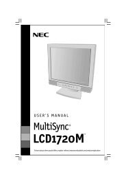
Step 3<br />
Connect up to 8 (<strong>SW8</strong>) or <strong>12</strong> (SW<strong>12</strong>) video input<br />
cables.<br />
I<br />
N<br />
P<br />
U<br />
T<br />
S<br />
Video inputs<br />
1<br />
2<br />
Step 4<br />
Connect up to 8 (<strong>SW8</strong>) or <strong>12</strong> (SW<strong>12</strong>) audio input<br />
cables.<br />
I<br />
N<br />
P<br />
U<br />
T<br />
S<br />
1<br />
2<br />
Audio inputs<br />
Step 5 (optional)<br />
a. If using one or more VSW I AAPs, connect<br />
the video and audio input devices through<br />
the VSW I AAP units to the switcher.<br />
COMPUTER<br />
3<br />
4<br />
3<br />
4<br />
AUDIO<br />
5<br />
6<br />
5<br />
6<br />
SHOW ME<br />
VSW I AAP<br />
b. Configure the switcher to operate with<br />
a VSW I AAP (see chapter 2 for more<br />
information).<br />
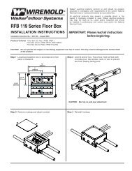
Step 6<br />
Connect one or two video output devices.<br />
O<br />
U<br />
T<br />
P<br />
U<br />
T<br />
S<br />
Quick Start — <strong>SW8</strong>/<strong>12</strong> <strong>VGA</strong> <strong>Ars</strong><br />
Video outputs<br />
1<br />
2<br />
FIXED VARIABLE<br />
L R L R<br />
7<br />
8<br />
7<br />
8<br />
Step 7<br />
Connect one or two audio devices to the<br />
switcher’s audio output ports.<br />
a. Wire the audio output connectors as<br />
shown below.<br />
Do not tin the wires!<br />
C<br />
<strong>SW8</strong>/<strong>12</strong> <strong>VGA</strong> <strong>Ars</strong> • Quick Start<br />
Connect the sleeves<br />
to ground ( ).<br />
Connecting a sleeve<br />
to a negative (-)<br />
terminal will damage<br />
the audio output<br />
circuits.<br />
b. Connect the audio output cables to the audio<br />
Fixed or Variable ports on the rear panel of<br />
the switcher.<br />
O<br />
U<br />
T<br />
P<br />
U<br />
T<br />
S<br />
1<br />
2<br />
Audio outputs<br />
FIXED VARIABLE<br />
L R L R<br />
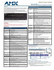
Step 8 (optional)<br />
Connect a serial cable from a control device to the<br />
RS-232 control port.<br />
Wire the cable as shown below:<br />
Pin 2 Transmit data<br />
Pin 3 Receive data<br />
Pin 5 Signal ground<br />
All other pins should have<br />
no connection.<br />
O<br />
U<br />
T<br />
P<br />
U<br />
T<br />
S<br />
Tip<br />
Ring<br />
Tip<br />
Ring<br />
Balanced<br />
Stereo Output<br />
Tip<br />
NO GROUND HERE.<br />
Sleeve(s)<br />
Tip<br />
NO GROUND HERE.<br />
Unbalanced<br />
Stereo Output<br />
1<br />
2<br />
FIXED VARIABLE<br />
L R L R<br />
5 1<br />
9 6<br />
DB9 Pin Locations<br />
Female<br />
SW<strong>12</strong> <strong>VGA</strong> <strong>Ars</strong><br />
RS-232<br />
RS-232 control port<br />
QS-1