
Create successful ePaper yourself
Turn your PDF publications into a flip-book with our unique Google optimized e-Paper software.
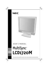
<strong>SW8</strong> <strong>VGA</strong> <strong>Ars</strong><br />
SW<strong>12</strong> <strong>VGA</strong> <strong>Ars</strong><br />
<strong>SW8</strong>/<strong>12</strong> <strong>VGA</strong> <strong>Ars</strong><br />
Computer Video and Audio Switchers<br />
68-1513-01 Rev. A<br />
05 08
Precautions<br />
Safety Instructions English<br />
This symbol is intended to alert the user of important operating and maintenance<br />
(servicing) instructions in the literature provided with the equipment.<br />
This symbol is intended to alert the user of the presence of uninsulated dangerous<br />
voltage within the product’s enclosure that may present a risk of electric shock.<br />
Caution<br />
Read Instructions Read and understand all safety and operating instructions before using the equipment.<br />
Retain Instructions The safety instructions should be kept for future reference.<br />
Follow Warnings Follow all warnings and instructions marked on the equipment or in the user<br />
information.<br />
Avoid Attachments Do not use tools or attachments that are not recommended by the equipment<br />
manufacturer because they may be hazardous.<br />
Consignes de Sécurité Français<br />
Ce symbole sert à avertir l’utilisateur que la documentation fournie avec le matériel<br />
contient des instructions importantes concernant l’exploitation et la maintenance<br />
(réparation).<br />
Ce symbole sert à avertir l’utilisateur de la présence dans le boîtier de l’appareil<br />
de tensions dangereuses non isolées posant des risques d’électrocution.<br />
Attention<br />
Lire les instructions Prendre connaissance de toutes les consignes de sécurité et d’exploitation avant<br />
d’utiliser le matériel.<br />
Conserver les instructions Ranger les consignes de sécurité afi n de pouvoir les consulter à l’avenir.<br />
Respecter les avertissements Observer tous les avertissements et consignes marqués sur le matériel ou<br />
présentés dans la documentation utilisateur.<br />
Eviter les pièces de fi xation Ne pas utiliser de pièces de fi xation ni d’outils non recommandés par le<br />
fabricant du matériel car cela risquerait de poser certains dangers.<br />
Sicherheitsanleitungen Deutsch<br />
Dieses Symbol soll dem Benutzer in der im Lieferumfang enthaltenen<br />
Dokumentation besonders wichtige Hinweise zur Bedienung und Wartung<br />
(Instandhaltung) geben.<br />
Dieses Symbol soll den Benutzer darauf aufmerksam machen, daß im Inneren des<br />
Gehäuses dieses Produktes gefährliche Spannungen, die nicht isoliert sind und<br />
die einen elektrischen Schock verursachen können, herrschen.<br />
Achtung<br />
Lesen der Anleitungen • Bevor Sie das Gerät zum ersten Mal verwenden, sollten Sie alle Sicherheits-und<br />
Bedienungsanleitungen genau durchlesen und verstehen.<br />
Aufbewahren der Anleitungen • Die Hinweise zur elektrischen Sicherheit des Produktes sollten Sie<br />
aufbewahren, damit Sie im Bedarfsfall darauf zurückgreifen können.<br />
Befolgen der Warnhinweise • Befolgen Sie alle Warnhinweise und Anleitungen auf dem Gerät oder in der<br />
Benutzerdokumentation.<br />
Keine Zusatzgeräte • Verwenden Sie keine Werkzeuge oder Zusatzgeräte, die nicht ausdrücklich vom<br />
Hersteller empfohlen wurden, da diese eine Gefahrenquelle darstellen können.<br />
Instrucciones de seguridad Español<br />
Este símbolo se utiliza para advertir al usuario sobre instrucciones importantes<br />
de operación y mantenimiento (o cambio de partes) que se desean destacar en el<br />
contenido de la documentación suministrada con los equipos.<br />
Este símbolo se utiliza para advertir al usuario sobre la presencia de elementos con<br />
voltaje peligroso sin protección aislante, que puedan encontrarse dentro de la caja<br />
o alojamiento del producto, y que puedan representar riesgo de electrocución.<br />
Precaucion<br />
Leer las instrucciones Leer y analizar todas las instrucciones de operación y seguridad, antes de usar el<br />
equipo.<br />
Conservar las instrucciones Conservar las instrucciones de seguridad para futura consulta.<br />
Obedecer las advertencias Todas las advertencias e instrucciones marcadas en el equipo o en la<br />
documentación del usuario, deben ser obedecidas.<br />
Evitar el uso de accesorios No usar herramientas o accesorios que no sean especifi camente recomendados<br />
por el fabricante, ya que podrian implicar riesgos.<br />
�����•���<br />
����������������������������<br />
�����������������������������<br />
��<br />
������• �������������������������<br />
������• �����������������<br />
�����• ������������������������<br />
�����• ����������������������������<br />
Warning<br />
Power sources This equipment should be operated only from the power source indicated on the product. This<br />
equipment is intended to be used with a main power system with a grounded (neutral) conductor. The<br />
third (grounding) pin is a safety feature, do not attempt to bypass or disable it.<br />
Power disconnection To remove power from the equipment safely, remove all power cords from the rear of<br />
the equipment, or the desktop power module (if detachable), or from the power source receptacle (wall<br />
plug).<br />
Power cord protection Power cords should be routed so that they are not likely to be stepped on or pinched by<br />
items placed upon or against them.<br />
Servicing Refer all servicing to qualifi ed service personnel. There are no user-serviceable parts inside. To<br />
prevent the risk of shock, do not attempt to service this equipment yourself because opening or removing<br />
covers may expose you to dangerous voltage or other hazards.<br />
Slots and openings If the equipment has slots or holes in the enclosure, these are provided to prevent<br />
overheating of sensitive components inside. These openings must never be blocked by other objects.<br />
Lithium battery There is a danger of explosion if battery is incorrectly replaced. Replace it only with the<br />
same or equivalent type recommended by the manufacturer. Dispose of used batteries according to the<br />
manufacturer’s instructions.<br />
Avertissement<br />
Alimentations Ne faire fonctionner ce matériel qu’avec la source d’alimentation indiquée sur l’appareil. Ce<br />
matériel doit être utilisé avec une alimentation principale comportant un fi l de terre (neutre). Le troisième<br />
contact (de mise à la terre) constitue un dispositif de sécurité : n’essayez pas de la contourner ni de la<br />
désactiver.<br />
Déconnexion de l’alimentation Pour mettre le matériel hors tension sans danger, déconnectez tous les cordons<br />
d’alimentation de l’arrière de l’appareil ou du module d’alimentation de bureau (s’il est amovible) ou<br />
encore de la prise secteur.<br />
Protection du cordon d’alimentation Acheminer les cordons d’alimentation de manière à ce que personne ne<br />
risque de marcher dessus et à ce qu’ils ne soient pas écrasés ou pincés par des objets.<br />
Réparation-maintenance Faire exécuter toutes les interventions de réparation-maintenance par un technicien<br />
qualifi é. Aucun des éléments internes ne peut être réparé par l’utilisateur. Afi n d’éviter tout danger<br />
d’électrocution, l’utilisateur ne doit pas essayer de procéder lui-même à ces opérations car l’ouverture ou le<br />
retrait des couvercles risquent de l’exposer à de hautes tensions et autres dangers.<br />
Fentes et orifi ces Si le boîtier de l’appareil comporte des fentes ou des orifi ces, ceux-ci servent à empêcher<br />
les composants internes sensibles de surchauffer. Ces ouvertures ne doivent jamais être bloquées par des<br />
objets.<br />
Lithium Batterie Il a danger d’explosion s’ll y a remplacment incorrect de la batterie. Remplacer uniquement<br />
avec une batterie du meme type ou d’un ype equivalent recommande par le constructeur. Mettre au reut les<br />
batteries usagees conformement aux instructions du fabricant.<br />
Vorsicht<br />
Stromquellen • Dieses Gerät sollte nur über die auf dem Produkt angegebene Stromquelle betrieben werden.<br />
Dieses Gerät wurde für eine Verwendung mit einer Hauptstromleitung mit einem geerdeten (neutralen)<br />
Leiter konzipiert. Der dritte Kontakt ist für einen Erdanschluß, und stellt eine Sicherheitsfunktion dar. Diese<br />
sollte nicht umgangen oder außer Betrieb gesetzt werden.<br />
Stromunterbrechung • Um das Gerät auf sichere Weise vom Netz zu trennen, sollten Sie alle Netzkabel<br />
aus der Rückseite des Gerätes, aus der externen Stomversorgung (falls dies möglich ist) oder aus der<br />
Wandsteckdose ziehen.<br />
Schutz des Netzkabels • Netzkabel sollten stets so verlegt werden, daß sie nicht im Weg liegen und niemand<br />
darauf treten kann oder Objekte darauf- oder unmittelbar dagegengestellt werden können.<br />
Wartung • Alle Wartungsmaßnahmen sollten nur von qualifi ziertem Servicepersonal durchgeführt werden.<br />
Die internen Komponenten des Gerätes sind wartungsfrei. Zur Vermeidung eines elektrischen Schocks<br />
versuchen Sie in keinem Fall, dieses Gerät selbst öffnen, da beim Entfernen der Abdeckungen die Gefahr<br />
eines elektrischen Schlags und/oder andere Gefahren bestehen.<br />
Schlitze und Öffnungen • Wenn das Gerät Schlitze oder Löcher im Gehäuse aufweist, dienen diese zur<br />
Vermeidung einer Überhitzung der empfi ndlichen Teile im Inneren. Diese Öffnungen dürfen niemals von<br />
anderen Objekten blockiert werden.<br />
Litium-Batterie • Explosionsgefahr, falls die Batterie nicht richtig ersetzt wird. Ersetzen Sie verbrauchte<br />
Batterien nur durch den gleichen oder einen vergleichbaren Batterietyp, der auch vom Hersteller<br />
empfohlen wird. Entsorgen Sie verbrauchte Batterien bitte gemäß den Herstelleranweisungen.<br />
Advertencia<br />
Alimentación eléctrica Este equipo debe conectarse únicamente a la fuente/tipo de alimentación eléctrica<br />
indicada en el mismo. La alimentación eléctrica de este equipo debe provenir de un sistema de distribución<br />
general con conductor neutro a tierra. La tercera pata (puesta a tierra) es una medida de seguridad, no<br />
puentearia ni eliminaria.<br />
Desconexión de alimentación eléctrica Para desconectar con seguridad la acometida de alimentación eléctrica<br />
al equipo, desenchufar todos los cables de alimentación en el panel trasero del equipo, o desenchufar el<br />
módulo de alimentación (si fuera independiente), o desenchufar el cable del receptáculo de la pared.<br />
Protección del cables de alimentación Los cables de alimentación eléctrica se deben instalar en lugares donde<br />
no sean pisados ni apretados por objetos que se puedan apoyar sobre ellos.<br />
Reparaciones/mantenimiento Solicitar siempre los servicios técnicos de personal califi cado. En el interior no<br />
hay partes a las que el usuario deba acceder. Para evitar riesgo de electrocución, no intentar personalmente<br />
la reparación/mantenimiento de este equipo, ya que al abrir o extraer las tapas puede quedar expuesto a<br />
voltajes peligrosos u otros riesgos.<br />
Ranuras y aberturas Si el equipo posee ranuras o orifi cios en su caja/alojamiento, es para evitar el<br />
sobrecalientamiento de componentes internos sensibles. Estas aberturas nunca se deben obstruir con otros<br />
objetos.<br />
Batería de litio Existe riesgo de explosión si esta batería se coloca en la posición incorrecta. Cambiar esta<br />
batería únicamente con el mismo tipo (o su equivalente) recomendado por el fabricante. Desachar las<br />
baterías usadas siguiendo las instrucciones del fabricante.<br />
��<br />
���• ���������������������������������������<br />
�������������������<br />
�����• ������������������������������������<br />
��������<br />
������• ������������������<br />
���•���������������������������������������<br />
�����������������������<br />
����• �������������������������������������<br />
�������<br />
����• �������������������������������������<br />
���������������
FCC Class A Notice<br />
This equipment has been tested and found to comply with the limits for a Class A digital device, pursuant to part 15 of the FCC Rules. Operation is subject to<br />
the following two conditions: (1) this device may not cause harmful interference, and (2) this device must accept any interference received, including interference<br />
that may cause undesired operation. The Class A limits are designed to provide reasonable protection against harmful interference when the equipment is<br />
operated in a commercial environment. This equipment generates, uses, and can radiate radio frequency energy and, if not installed and used in accordance with<br />
the instruction manual, may cause harmful interference to radio communications. Operation of this equipment in a residential area is likely to cause harmful<br />
interference, in which case the user will be required to correct the interference at his own expense.<br />
N This unit was tested with shielded cables on the peripheral devices. Shielded cables must be used with the unit to ensure compliance with FCC emissions limits.
Step 1<br />
Power off all devices.<br />
Step 2<br />
Mount the switcher in a rack, or place it in the<br />
desired location.<br />
Step 3<br />
Connect up to 8 (<strong>SW8</strong>) or <strong>12</strong> (SW<strong>12</strong>) video input<br />
cables.<br />
I<br />
N<br />
P<br />
U<br />
T<br />
S<br />
Video inputs<br />
1<br />
2<br />
Step 4<br />
Connect up to 8 (<strong>SW8</strong>) or <strong>12</strong> (SW<strong>12</strong>) audio input<br />
cables.<br />
I<br />
N<br />
P<br />
U<br />
T<br />
S<br />
1<br />
2<br />
Audio inputs<br />
Step 5 (optional)<br />
a. If using one or more VSW I AAPs, connect<br />
the video and audio input devices through<br />
the VSW I AAP units to the switcher.<br />
COMPUTER<br />
3<br />
4<br />
3<br />
4<br />
AUDIO<br />
5<br />
6<br />
5<br />
6<br />
SHOW ME<br />
VSW I AAP<br />
b. Configure the switcher to operate with<br />
a VSW I AAP (see chapter 2 for more<br />
information).<br />
Step 6<br />
Connect one or two video output devices.<br />
O<br />
U<br />
T<br />
P<br />
U<br />
T<br />
S<br />
Quick Start — <strong>SW8</strong>/<strong>12</strong> <strong>VGA</strong> <strong>Ars</strong><br />
Video outputs<br />
1<br />
2<br />
FIXED VARIABLE<br />
L R L R<br />
7<br />
8<br />
7<br />
8<br />
Step 7<br />
Connect one or two audio devices to the<br />
switcher’s audio output ports.<br />
a. Wire the audio output connectors as<br />
shown below.<br />
Do not tin the wires!<br />
C<br />
<strong>SW8</strong>/<strong>12</strong> <strong>VGA</strong> <strong>Ars</strong> • Quick Start<br />
Connect the sleeves<br />
to ground ( ).<br />
Connecting a sleeve<br />
to a negative (-)<br />
terminal will damage<br />
the audio output<br />
circuits.<br />
b. Connect the audio output cables to the audio<br />
Fixed or Variable ports on the rear panel of<br />
the switcher.<br />
O<br />
U<br />
T<br />
P<br />
U<br />
T<br />
S<br />
1<br />
2<br />
Audio outputs<br />
FIXED VARIABLE<br />
L R L R<br />
Step 8 (optional)<br />
Connect a serial cable from a control device to the<br />
RS-232 control port.<br />
Wire the cable as shown below:<br />
Pin 2 Transmit data<br />
Pin 3 Receive data<br />
Pin 5 Signal ground<br />
All other pins should have<br />
no connection.<br />
O<br />
U<br />
T<br />
P<br />
U<br />
T<br />
S<br />
Tip<br />
Ring<br />
Tip<br />
Ring<br />
Balanced<br />
Stereo Output<br />
Tip<br />
NO GROUND HERE.<br />
Sleeve(s)<br />
Tip<br />
NO GROUND HERE.<br />
Unbalanced<br />
Stereo Output<br />
1<br />
2<br />
FIXED VARIABLE<br />
L R L R<br />
5 1<br />
9 6<br />
DB9 Pin Locations<br />
Female<br />
SW<strong>12</strong> <strong>VGA</strong> <strong>Ars</strong><br />
RS-232<br />
RS-232 control port<br />
QS-1
QS-2<br />
Quick Start — <strong>SW8</strong>/<strong>12</strong> <strong>VGA</strong> <strong>Ars</strong>, cont’d<br />
Step 9<br />
Connect power cords and apply power in the following order:<br />
• Output devices (displays, projectors, monitors, audio devices, etc.)<br />
• <strong>SW8</strong>/<strong>12</strong> <strong>VGA</strong> <strong>Ars</strong> switcher<br />
• Input devices (computers, audio devices, etc.)<br />
Step 10<br />
Make the Normal/Auto Switch mode selection:<br />
• Normal — Hold Mode button and press Normal button. The Auto Switch LED is off. All input<br />
buttons function normally.<br />
• Auto switch — Hold Mode button and press Auto button. The Auto Switch LED is on. Front<br />
panel input buttons are locked out. The switcher outputs highest number input that has a sync signal<br />
present. If no sync signal is present, input #1 is selected by default.<br />
AUTO SWITCH<br />
ACTIVE<br />
1 2 3<br />
MODE NORMAL AUTO<br />
Step 11<br />
If Normal mode was selected above, press any input button to make an input selection. The selected<br />
button’s LED lights and the selected input’s video and audio signals are delivered to the output<br />
device(s).<br />
AUTO SWITCH<br />
ACTIVE<br />
1 2 3 4 5 6 7 8<br />
MODE NORMAL AUTO<br />
Troubleshooting<br />
If video/audio signals are not present on the output device(s):<br />
1. Power off all devices and re-apply power in the order described in Step 9 above.<br />
2. Check all power, input, and output cabling.<br />
3. If in Normal mode, select a different input device.<br />
4. If in Auto Switch mode, confirm that at least one input device is delivering a signal to the<br />
switcher.<br />
<strong>SW8</strong>/<strong>12</strong> <strong>VGA</strong> <strong>Ars</strong> • Quick Start
Table of Contents<br />
Chapter One • Introduction ......................................................................................................1-1<br />
About This Manual ....................................................................................................................1-2<br />
About the <strong>SW8</strong>/<strong>12</strong> <strong>VGA</strong> <strong>Ars</strong> Switchers ..........................................................................1-2<br />
Features ............................................................................................................................................1-3<br />
Chapter Two • Installation and Operation ...................................................................2-1<br />
Mounting the <strong>SW8</strong>/<strong>12</strong> <strong>VGA</strong> <strong>Ars</strong> Switcher ....................................................................2-2<br />
Desktop placement ...................................................................................................................2-2<br />
Rack mounting
Table of Contents, cont’d<br />
ii<br />
Appendix A • Specifications, Part Numbers, Accessories ................................ A-1<br />
Specifications .............................................................................................................................. A-2<br />
Part Numbers and Accessories .......................................................................................... A-4<br />
<strong>SW8</strong>/<strong>12</strong> <strong>VGA</strong> <strong>Ars</strong> switchers ...................................................................................................... A-4<br />
Included parts ........................................................................................................................... A-4<br />
Cables and Adapters ................................................................................................................ A-4<br />
Accessories ................................................................................................................................ A-4<br />
All trademarks mentioned in this manual are the properties of their respective owners.<br />
<strong>SW8</strong>/<strong>12</strong> <strong>VGA</strong> <strong>Ars</strong> • Table of Contents<br />
68-1513-01 A<br />
05 08
<strong>SW8</strong>/<strong>12</strong> <strong>VGA</strong> <strong>Ars</strong><br />
1<br />
Chapter One<br />
Introduction<br />
About This Manual<br />
About the <strong>SW8</strong>/<strong>12</strong> <strong>VGA</strong> <strong>Ars</strong> Switchers<br />
Features
Introduction<br />
1-2<br />
About This Manual<br />
This manual describes the function, installation, operation, and control of the<br />
<strong>SW8</strong> <strong>VGA</strong> <strong>Ars</strong> and SW<strong>12</strong> <strong>VGA</strong> <strong>Ars</strong>, 8- or <strong>12</strong>-input, 2-output computer video (<strong>VGA</strong>)<br />
and audio switchers.<br />
About the <strong>SW8</strong>/<strong>12</strong> <strong>VGA</strong> <strong>Ars</strong> Switchers<br />
The Extron <strong>SW8</strong>/<strong>12</strong> <strong>VGA</strong> <strong>Ars</strong> switchers support audio video (A/V) systems that<br />
require 8 or <strong>12</strong> high resolution <strong>VGA</strong>-QXGA video and audio inputs to be switched<br />
to 1 or 2 outputs.<br />
Video and audio outputs are buffered. Selected input signals are delivered to both<br />
video outputs and both audio outputs simultaneously.<br />
Extron<br />
SW<strong>12</strong> <strong>VGA</strong> <strong>Ars</strong><br />
<strong>VGA</strong> w/ Audio<br />
Switcher<br />
INTERFACE AAP I<br />
COMPUTER AUDIO SHOW ME<br />
100-240V 50/60Hz<br />
Extron<br />
Laptop<br />
VSW I AAP<br />
Architechtural Adapter Plate<br />
<strong>SW8</strong>/<strong>12</strong> <strong>VGA</strong> <strong>Ars</strong> • Introduction<br />
1.2A MAX<br />
I<br />
N<br />
P<br />
U<br />
T<br />
S<br />
1<br />
2<br />
3<br />
4<br />
5<br />
6<br />
7<br />
8<br />
9<br />
10<br />
Extron<br />
MPA <strong>12</strong>2<br />
Mini Power<br />
Amplifier<br />
11<br />
<strong>12</strong><br />
INTERFACE AAP I<br />
COMPUTER AUDIO SHOW ME<br />
O<br />
U<br />
T<br />
P<br />
U<br />
T<br />
S<br />
POWER<br />
SW<strong>12</strong> <strong>VGA</strong> <strong>Ars</strong><br />
L<br />
R<br />
INPUTS<br />
C US<br />
L R<br />
Local<br />
Monitor<br />
Extron<br />
Laptop<br />
VSW I AAP<br />
Architechtural Adapter Plate<br />
1<br />
2<br />
FIXED VARIABLE<br />
L R L R<br />
RS-232<br />
OUTPUTS<br />
4/8 Ohms SPEAKERS<br />
L R<br />
REMOTE<br />
Figure 1-1 — A typical SW<strong>12</strong> <strong>VGA</strong> <strong>Ars</strong> switcher application<br />
10V<br />
VOL/MUTE<br />
MPA <strong>12</strong>2<br />
System Control<br />
Projector<br />
8 ohm Ceiling<br />
Speakers<br />
in Parallel
Features <strong>SW8</strong>/<strong>12</strong> <strong>VGA</strong> <strong>Ars</strong> switcher features include:<br />
• 8 or <strong>12</strong> video inputs with 15-pin HD connectors<br />
• 8 or <strong>12</strong> 3.5 mm stereo mini jacks for audio<br />
• Two 15-pin HD output connectors for video<br />
• Two captive screw output connectors for audio<br />
• Compatible with <strong>VGA</strong>-QXGA and HDTV component video signals<br />
• 350 MHz (-3 dB) RGB video bandwidth<br />
• Automatically detects which inputs have an active signal and reports this<br />
information through the RS-232 port<br />
• Balanced / unbalanced audio outputs<br />
• Variable / fixed audio outputs<br />
• Autoswitching capabilities<br />
• Executive mode (front panel lockout)<br />
• Multiple control options — front panel, autoswitch, RS-232, IR via IR 102<br />
• VSW I AAP compatibility<br />
• Internal international power supply<br />
• Multiple mounting options — rack, under desk, through desk, tabletop<br />
<strong>SW8</strong>/<strong>12</strong> <strong>VGA</strong> <strong>Ars</strong> • Introduction<br />
1-3
Introduction, cont’d<br />
1-4<br />
<strong>SW8</strong>/<strong>12</strong> <strong>VGA</strong> <strong>Ars</strong> • Introduction
<strong>SW8</strong>/<strong>12</strong> <strong>VGA</strong> <strong>Ars</strong><br />
2<br />
Chapter Two<br />
Installation and Operation<br />
Mounting
Installation and Operation<br />
2-2<br />
Mounting the <strong>SW8</strong>/<strong>12</strong> <strong>VGA</strong> <strong>Ars</strong> Switcher<br />
The <strong>SW8</strong>/<strong>12</strong> <strong>VGA</strong> <strong>Ars</strong> can be placed on a desktop or easily mounted:<br />
• In a rack<br />
• Under a desktop<br />
• Through a desktop<br />
Desktop placement<br />
Affix the four included rubber feet to the bottom of the unit and place it in any<br />
convenient location.<br />
Rack mounting<br />
UL guidelines for rack mounting<br />
The following Underwriters Laboratories (UL) guidelines pertain to the installation<br />
of an <strong>SW8</strong>/<strong>12</strong> <strong>VGA</strong> <strong>Ars</strong> switcher unit onto a rack.<br />
1. Elevated operating ambient — If installed in a closed or multi-unit rack<br />
assembly, the operating ambient temperature of the rack environment may be<br />
greater than room ambient. Therefore, consider installing the equipment in an<br />
environment compatible with the maximum ambient temperature specified<br />
by Extron (Tma = +32 to +<strong>12</strong>2 °F [0 to +50 °C]).<br />
2. Reduced air flow — Installation of the equipment in a rack should be such<br />
that the amount of air flow required for safe operation of the equipment is not<br />
compromised.<br />
3. Mechanical loading — Mounting of the equipment in the rack should be such<br />
that a hazardous condition is not achieved due to uneven mechanical loading.<br />
4. Circuit overloading — Consideration should be given to the connection of the<br />
equipment to the supply circuit and the effect that overloading of the circuits<br />
might have on overcurrent protection and supply wiring. Appropriate<br />
consideration of equipment nameplate ratings should be used when<br />
addressing this concern.<br />
5. Reliable earthing (grounding) — Reliable earthing of rack-mounted<br />
equipment should be maintained. Particular attention should be given to<br />
supply connections other than direct connections to the branch circuit (such as<br />
the use of power strips).<br />
<strong>SW8</strong>/<strong>12</strong> <strong>VGA</strong> <strong>Ars</strong> • Installation and Operation
Mounting instructions<br />
Rack mounting requires the included MBD 149 1U, through-desk and rack<br />
mounting kit (part #70-077-03).<br />
Rack mount an <strong>SW8</strong>/<strong>12</strong> <strong>VGA</strong> <strong>Ars</strong> unit as follows:<br />
1. If present, remove the four rubber feet from the bottom of the unit.<br />
2. Use four supplied 8-32 x 5/16” long screws to secure a mounting bracket to<br />
each side of the unit (figure 2-1).<br />
3. Use four supplied 10-32 x 3/4” long screws to secure the bracket to the rail.<br />
Bracket<br />
Screws<br />
Mounting<br />
Screws<br />
Figure 2-1 — Rack mounting the switcher<br />
Rack Mount<br />
Bracket<br />
<strong>SW8</strong>/<strong>12</strong> <strong>VGA</strong> <strong>Ars</strong> • Installation and Operation<br />
Mounting<br />
Screws<br />
2-3
Installation and Operation, cont’d<br />
2-4<br />
Mounting under a desktop<br />
Under-desk mounting requires the optional MBU 149 1U, under-desk mounting kit<br />
(part #70-222-01).<br />
Mount an <strong>SW8</strong>/<strong>12</strong> <strong>VGA</strong> <strong>Ars</strong> under a desktop as follows:<br />
1. Install the mounting brackets on the unit’s sides with the eight machine<br />
screws provided in the kit.<br />
2. Hold the unit (with brackets attached) against the underside of the desk.<br />
Mark each bracket's hole location on the underside of the desk.<br />
3. Drill 1/4" (6.4 mm) deep, 3/32" (2 mm) diameter pilot holes from the<br />
underside of the desk at the marked hole locations.<br />
4. Insert the four wood screws into the pilot holes and tighten until<br />
approximately 1/4" (6.4 mm) of the screw's head is protruding.<br />
5. Install the mounting brackets, with the unit attached, over the protruding<br />
screw heads.<br />
6. Slide the unit slightly to lock it in place.<br />
7. Tighten all four screws to secure it in place.<br />
#8 Screw<br />
(4 Plcs)<br />
Each Side<br />
Optional Furniture Mounting Bracket<br />
<strong>SW8</strong>/<strong>12</strong> <strong>VGA</strong> <strong>Ars</strong> • Installation and Operation<br />
Mounting Screws<br />
(2 Plcs)<br />
Each Side<br />
Figure 2-2 — Mounting the switcher under a desktop
Mounting through a desktop<br />
Through desktop mounting requires the included MBD 149 1U, through-desk and<br />
rack mounting kit (part #70-077-03).<br />
Mount an <strong>SW8</strong>/<strong>12</strong> <strong>VGA</strong> <strong>Ars</strong> unit through a desktop as follows:<br />
1. If present, remove the four rubber feet from the bottom of the unit.<br />
2. Cut an appropriately sized hole in the desktop.<br />
3. Loosely install the mounting brackets on the unit’s sides with four machine<br />
screws provided in the kit.<br />
4. Hold the unit (with brackets attached) against the underside of the desk.<br />
Mark each bracket's hole location on the underside of the desk.<br />
5. Drill 1/4" (6.4 mm) deep, 3/32" (2 mm) diameter pilot holes from the<br />
underside of the desk at the marked hole locations.<br />
6. Hold the unit in place so the mounting bracket holes line up with the pilot<br />
holes in the desktop.<br />
7. Install the four supplied wood screws through the mounting brackets and into<br />
the pilot holes.<br />
8. Tighten the wood screws to secure the mounting brackets to the underside of<br />
the desktop.<br />
9. Slide the switcher up or down inside the mounting brackets to achieve the<br />
desired height above the desktop.<br />
10. Tighten the machine screws to secure the switcher in position.<br />
Figure 2-3 — Mounting the switcher through a desktop<br />
<strong>SW8</strong>/<strong>12</strong> <strong>VGA</strong> <strong>Ars</strong> • Installation and Operation<br />
2-5
Installation and Operation, cont’d<br />
2-6<br />
Rear Panel<br />
The <strong>SW8</strong>/<strong>12</strong> <strong>VGA</strong> <strong>Ars</strong> switcher rear panel connectors are described below.<br />
1 2 3<br />
100-240V 50/60Hz<br />
1.2A MAX<br />
I<br />
N<br />
P<br />
U<br />
T<br />
S<br />
1<br />
2<br />
Figure 2-4 — <strong>SW8</strong> <strong>VGA</strong> <strong>Ars</strong> rear panel<br />
1 2 3<br />
100-240V 50/60Hz<br />
1.2A MAX<br />
I<br />
N<br />
P<br />
U<br />
T<br />
S<br />
1<br />
2<br />
Figure 2-5 — SW<strong>12</strong> <strong>VGA</strong> <strong>Ars</strong> rear panel<br />
a<br />
b<br />
c<br />
d<br />
e<br />
f<br />
g<br />
3<br />
4<br />
3<br />
4<br />
<strong>SW8</strong>/<strong>12</strong> <strong>VGA</strong> <strong>Ars</strong> • Installation and Operation<br />
5<br />
6<br />
5<br />
6<br />
7<br />
8<br />
7<br />
8<br />
9<br />
10<br />
11<br />
<strong>12</strong><br />
O<br />
U<br />
T<br />
P<br />
U<br />
T<br />
S<br />
O<br />
U<br />
T<br />
P<br />
U<br />
T<br />
S<br />
4<br />
4<br />
1<br />
2<br />
1<br />
2<br />
5 6 7<br />
FIXED VARIABLE<br />
L R L R<br />
FIXED VARIABLE<br />
L R L R<br />
<strong>SW8</strong> <strong>VGA</strong> <strong>Ars</strong><br />
RS-232<br />
5 6 7<br />
SW<strong>12</strong> <strong>VGA</strong> <strong>Ars</strong><br />
AC power receptacle — Plug a standard IEC power cord into this receptacle<br />
to connect the switcher to a <strong>12</strong>0/240 VAC, 50/60 Hz power source.<br />
Computer video input connectors — 8 or <strong>12</strong> 15-pin HD female connectors.<br />
Connect computer video inputs (<strong>VGA</strong>, S<strong>VGA</strong>, XGA, SXGA, WXGA, SXGA+,<br />
UXGA, QXGA, or HDTV).<br />
Audio input connectors — Eight or twelve 3.5mm TRS jacks. Connect<br />
unbalanced audio inputs.<br />
Video output connectors — Two 15-pin HD female connectors deliver<br />
simultaneous buffered video output.<br />
Fixed audio output connector — One 3.5mm 5-pole captive screw connector<br />
delivers a fixed stereo balanced/unbalanced audio output.<br />
Variable audio output connector — One 3.5mm 5-pole captive screw<br />
connector delivers a variable stereo balanced/unbalanced audio output.<br />
Volume is variable via the RS-232 control port. The volume adjustment range<br />
is 0 (-84 dB) through 100 (0 db). The default volume setting is 100 (0 dB).<br />
RS-232 Control port — A 9-pin D female connector for serial connection to a<br />
PC or controller.<br />
RS-232
Cable Connections<br />
Power connection<br />
When you are ready to apply power to your <strong>SW8</strong>/<strong>12</strong> <strong>VGA</strong> <strong>Ars</strong> unit, connect the<br />
female end of the power cord to the AC outlet at the left edge of the rear panel,<br />
and connect the male end of the power cord to a <strong>12</strong>0/240 VAC power outlet.<br />
When power is applied all front panel LEDs light for one second, then go out.<br />
The LED for the previously selected input then comes on and remains lit until the<br />
current input is de-selected.<br />
100-240V 50/60Hz<br />
1.2A MAX<br />
Power connector<br />
I<br />
N<br />
P<br />
U<br />
T<br />
S<br />
Figure 2-6 — Power connector<br />
1<br />
2<br />
Computer video input connections<br />
Depending on the model (<strong>SW8</strong> or SW<strong>12</strong>) there are 8 or <strong>12</strong> video input ports on the<br />
rear panel.<br />
Each 15-pin HD female connector supports computer video signals with resolutions<br />
from <strong>VGA</strong> - QXGA and HDTV signals.<br />
10<br />
5 1<br />
15 11<br />
Female<br />
6<br />
Figure 2-7 Video input connectors<br />
<strong>SW8</strong>/<strong>12</strong> <strong>VGA</strong> <strong>Ars</strong> switchers monitor each input port for the presence of a<br />
horizontal sync pulse, which indicates the presence of a video signal. When<br />
detected, the video signal’s presence is reported on the switcher’s RS-232 control<br />
port. See chapter 3, “Operation and Control” for information on the Simple<br />
Instruction Set (SIS ) commands which can be used to communicate through the<br />
RS-232 port.<br />
The SIS command 0S requests the switcher to report the status of all inputs at once.<br />
The SIS command xS requests the status of specific port “x”.<br />
3<br />
4<br />
<strong>SW8</strong>/<strong>12</strong> <strong>VGA</strong> <strong>Ars</strong> • Installation and Operation<br />
2-7
Installation and Operation, cont’d<br />
2-8<br />
Audio input connections<br />
The switchers have 8 or <strong>12</strong> 3.5mm female audio jacks adjacent to the corresponding<br />
computer video input port.<br />
Pin Name Connection 3.5mm Stereo Connector<br />
1 Tip left channel Tip (L+) Sleeve (Gnd)<br />
2 Ring right channel<br />
3 Sleeve signal ground<br />
100-240V 50/60Hz<br />
1.2A MAX<br />
<strong>SW8</strong>/<strong>12</strong> <strong>VGA</strong> <strong>Ars</strong> • Installation and Operation<br />
I<br />
N<br />
P<br />
U<br />
T<br />
S<br />
Figure 2-8 — Audio input connectors<br />
1<br />
2<br />
3<br />
4<br />
Ring (R+)<br />
Audio input ports<br />
Tip (L+)<br />
Sleeve (Gnd)<br />
Video output connections<br />
The <strong>SW8</strong>/<strong>12</strong> <strong>VGA</strong> <strong>Ars</strong> switchers have two output ports that provide simultaneous,<br />
buffered video output of the selected video input signal.<br />
Outputs are delivered on two 15-pin HD female connectors (identical to the input<br />
connectors). The output signal type follows the input signal type.<br />
10<br />
5 1<br />
15 11<br />
Female<br />
6<br />
Figure 2-9 — Video output connectors<br />
ID bits associated with pins 4, 11, <strong>12</strong>, and 15 are routed from the selected input to<br />
output #1.<br />
The output device must be powered on prior to the input device for the ID bits to<br />
be properly routed to the output device.
Audio output connections<br />
The switcher have two 3.5mm 5-pole captive screw audio output ports.<br />
The Fixed port delivers a fixed volume, stereo balanced/unbalanced audio output.<br />
The Variable port delivers a variable volume, stereo balanced/unbalanced audio<br />
output. The volume range is 0 (-84 dB) through 100 (0 dB). The default volume<br />
setting is 100 (0 dB). Volume is controllable only via the RS-232 port.<br />
O<br />
U<br />
T<br />
P<br />
U<br />
T<br />
S<br />
1<br />
2<br />
FIXED VARIABLE<br />
L R L R<br />
Audio output ports<br />
SW<strong>12</strong> <strong>VGA</strong> <strong>Ars</strong><br />
RS-232<br />
Figure 2-10 — Audio output connectors<br />
Connect the captive screw connectors as shown below.<br />
C Connect the sleeve to ground ( ). Connecting the sleeve to a<br />
negative (-) terminal will damage the audio output circuits.<br />
Do not tin the wires!<br />
Tip<br />
NO GROUND HERE.<br />
Sleeve(s)<br />
Tip<br />
NO GROUND HERE.<br />
Unbalanced<br />
Stereo Output<br />
Figure 2-11 — Captive screw connectors<br />
Tip<br />
Ring<br />
Tip<br />
Ring<br />
Balanced<br />
Stereo Output<br />
N A balanced audio output provides a +6 dB gain. An unbalanced audio output<br />
provides a 0 dB gain.<br />
Remote control connection<br />
An RS-232 serial control port at the right edge of the rear panel is used for computer<br />
or infrared (IR) remote control of the device. The switcher’s firmware can be<br />
upgraded through the RS-232 port. See chapter 3, “Operation and Control”.<br />
The RS-232 port communications protocols are: 9600 baud, 8 data bits, 1 stop bit,<br />
no parity, and no flow control.<br />
IR remote control requires use of the IR 102 Remote Control Kit (part #70-224-01)<br />
For computer or infrared remote control, only pins 2 (transmit data), 3 (receive<br />
data), and 5 (ground) are required. Disconnect all other conductors in the<br />
attachment cable for proper operation.<br />
O<br />
U<br />
T<br />
P<br />
U<br />
T<br />
S<br />
1<br />
2<br />
FIXED VARIABLE<br />
L R L R<br />
SW<strong>12</strong> <strong>VGA</strong> <strong>Ars</strong><br />
RS-232<br />
RS-232 control port<br />
Figure 2-<strong>12</strong> — RS-232 control port<br />
5 1<br />
9 6<br />
DB9 Pin Locations<br />
Female<br />
<strong>SW8</strong>/<strong>12</strong> <strong>VGA</strong> <strong>Ars</strong> • Installation and Operation<br />
2-9
Installation and Operation, cont’d<br />
2-10<br />
VSW I AAP connection<br />
The VSW I AAP (part #70-529-11, -21, -51) is an optional Architectural Adapter Plate<br />
that provides remote input connection and selection for some Extron switchers.<br />
The VSW I AAP can be connected to the <strong>SW8</strong>/<strong>12</strong> <strong>VGA</strong> <strong>Ars</strong> input ports for input<br />
selection control.<br />
The VSW I AAP is equipped with a “Show Me” button for input selection, a female<br />
15-pin HD <strong>VGA</strong> connector, and a 3.5 mm stereo audio jack.<br />
COMPUTER<br />
AUDIO<br />
Figure 2-13 — VSW I AAP<br />
<strong>SW8</strong>/<strong>12</strong> <strong>VGA</strong> <strong>Ars</strong> • Installation and Operation<br />
SHOW ME<br />
VSW I AAP<br />
When the “Show Me” button is pressed, pin 5 on the switcher’s 15-pin HD input<br />
is momentarily shorted to ground. This overrides the switcher’s current input<br />
selection, and directs video and audio from the VSW I AAP’s connected device to<br />
the switcher’s output ports.<br />
For the VSW I AAP to operate with a switcher, the VSW I AAP PCB jumper must be<br />
set properly, and the switcher must be configured via its RS-232 control port.<br />
The VSW I AAP can be mounted into any Extron mounting frame with a single<br />
space AAP opening.<br />
The illustration on the following page shows a typical <strong>SW8</strong> <strong>VGA</strong> <strong>Ars</strong> switcher<br />
application with four VSW I AAP units connected to the switcher’s input ports.<br />
To use a VSW I AAP with a switcher:<br />
1. Confirm that jumper J5 is removed and jumper J6 is in place on the<br />
VSW I AAP’s printed circuit board.<br />
J5 J6<br />
Figure 2-14 — VSW I AAP jumpers<br />
2. Apply power to the switcher.<br />
3. Connect a host computer to the switcher’s RS-232 control port.<br />
4. Open a hyperterminal session on the host computer, and use a Simple<br />
Instruction Set (SIS ) command to configure the switcher to operate with a<br />
VSW I AAP (see chapter 3, “Operation and Control”).<br />
5. Connect a <strong>VGA</strong> cable from the VSW I AAP’s output connector to one of the<br />
switcher’s input ports.
COMPUTER<br />
Extron<br />
VSW I AAP<br />
AUDIO<br />
Extron<br />
HSA 400<br />
<strong>12</strong>5 - 50/60 Hz 5A<br />
6. Connect a <strong>VGA</strong> cable from an input device to the Computer input port on the<br />
VSW I AAP.<br />
7. Apply power to the display device, the switcher, and then the input source.<br />
8. Press the “Show Me” button on the VSW I AAP. The video input to the<br />
VSW I AAP is directed to the switcher’s output ports and should now be<br />
present on the display device.<br />
9. If desired, connect an audio input to the VSW I AAP, and use the “Show Me“<br />
button to test its output to the system’s audio output device.<br />
SHOW ME<br />
VSW I AAP<br />
COMPUTER<br />
HSA 400<br />
Extron<br />
MPA <strong>12</strong>2<br />
Conference Room<br />
<strong>12</strong>5 - 50/60 Hz 5A<br />
INPUT<br />
SELECT<br />
H. SHIFT<br />
AUDIO<br />
COMPUTER<br />
RGB 580xi SI AAP<br />
HSA 400<br />
<strong>12</strong>5 - 50/60 Hz 5A<br />
INPUT<br />
SELECT<br />
H. SHIFT<br />
AUDIO<br />
COMPUTER<br />
RGB 580xi SI AAP<br />
HSA 400<br />
POWER<br />
INPUTS<br />
<strong>12</strong>V<br />
3A MAX.<br />
L<br />
R<br />
C US<br />
L R<br />
REMOTE<br />
MPA <strong>12</strong>2<br />
OUTPUTS<br />
4/8 Ohms SPEAKERS<br />
L R<br />
10V<br />
VOL/MUTE<br />
<strong>12</strong>5 - 50/60 Hz 5A<br />
INPUT<br />
SELECT<br />
H. SHIFT<br />
AUDIO<br />
COMPUTER<br />
RGB 580xi SI AAP<br />
HSA 400<br />
Extron<br />
<strong>SW8</strong> <strong>VGA</strong> <strong>Ars</strong><br />
Figure 2-15 — A typical switcher application w/VSW I AAP units<br />
100-240V 50/60Hz<br />
1.2A MAX<br />
I<br />
N<br />
P<br />
U<br />
T<br />
S<br />
<strong>SW8</strong>/<strong>12</strong> <strong>VGA</strong> <strong>Ars</strong> • Installation and Operation<br />
1<br />
2<br />
<strong>12</strong>5 - 50/60 Hz 5A<br />
INPUT<br />
SELECT<br />
H. SHIFT<br />
AUDIO<br />
COMPUTER<br />
RGB 580xi SI AAP<br />
HSA 400<br />
3<br />
4<br />
5<br />
6<br />
7<br />
8<br />
O<br />
U<br />
T<br />
P<br />
U<br />
T<br />
S<br />
1<br />
2<br />
FIXED VARIABLE<br />
L R L R<br />
<strong>SW8</strong> <strong>VGA</strong> <strong>Ars</strong><br />
RS-232<br />
2-11
Installation and Operation, cont’d<br />
2-<strong>12</strong><br />
IR 102 remote control connection<br />
The <strong>SW8</strong>/<strong>12</strong> <strong>VGA</strong> <strong>Ars</strong> switcher can be controlled via its RS-232 port and an infrared<br />
signal. The IR 102 Remote Control Kit (part #70-224-01) is required.<br />
100-240V 50/60Hz<br />
1.2A MAX<br />
To connect an IR 102 Receiver to an <strong>SW8</strong>/<strong>12</strong> <strong>VGA</strong> <strong>Ars</strong> switcher:<br />
1. Connect a 9-pin serial cable, with only conductors 2, 3, and 5 connected, to the<br />
RS-232 output port on the IR 102 receiver.<br />
2. Connect the serial cable to the RS-232 port on the switcher’s rear panel.<br />
I<br />
N<br />
P<br />
U<br />
T<br />
S<br />
1<br />
2<br />
IR 102<br />
3<br />
4<br />
IR 102 Remote Control<br />
<strong>SW8</strong>/<strong>12</strong> <strong>VGA</strong> <strong>Ars</strong> • Installation and Operation<br />
5<br />
6<br />
+10<br />
7<br />
8<br />
SW<strong>12</strong> <strong>VGA</strong> <strong>Ars</strong> Switcher<br />
9<br />
10<br />
11<br />
<strong>12</strong><br />
O<br />
U<br />
T<br />
P<br />
U<br />
T<br />
S<br />
IR Detector<br />
1<br />
FIXED VARIABLE<br />
L R L R<br />
2<br />
6' Cable<br />
SW<strong>12</strong> <strong>VGA</strong> <strong>Ars</strong><br />
RS-232<br />
6.5' Cable<br />
IR 102 Remote<br />
Control Receiver<br />
RS-232<br />
Control<br />
Power<br />
Supply<br />
Figure 2-16 — A typical switcher application w/IR 102 remote control<br />
IR-102
1<br />
AUTO SWITCH<br />
ACTIVE<br />
1<br />
AUTO SWITCH<br />
ACTIVE<br />
Front Panel<br />
The <strong>SW8</strong>/<strong>12</strong> <strong>VGA</strong> <strong>Ars</strong> switcher front panel controls are described below.<br />
1 2 3 4 5 6 7 8<br />
MODE NORMAL AUTO<br />
3<br />
4 5<br />
2<br />
Figure 2-17 — <strong>SW8</strong> <strong>VGA</strong> <strong>Ars</strong> front panel<br />
1 2 3 4 5 6 7 8 9 10 11 <strong>12</strong><br />
MODE NORMAL AUTO<br />
3<br />
4 5<br />
2<br />
Figure 2-18 — SW<strong>12</strong> <strong>VGA</strong> <strong>Ars</strong> front panel<br />
a<br />
b<br />
c<br />
<strong>SW8</strong>/<strong>12</strong> <strong>VGA</strong> <strong>Ars</strong> • Installation and Operation<br />
<strong>SW8</strong> <strong>VGA</strong> <strong>Ars</strong><br />
SW <strong>12</strong> <strong>VGA</strong> <strong>Ars</strong><br />
Auto switch active LED — Lights when the auto switch mode is enabled.<br />
Input buttons and LEDs— Depending on the model there are eight or twelve<br />
input buttons and corresponding LEDs. To select an input, press the desired<br />
input button. The adjacent LED lights.<br />
Mode (Input 1) button — The Mode button functions in conjunction with<br />
other buttons as shown in the table below. Mode is a secondary function of<br />
the Input 1 button.<br />
Hold Press Description and Result<br />
Mode Normal Enable Normal mode — Front panel input buttons operate normally.<br />
Auto Switch Active LED is off.<br />
Mode Auto Enable Auto switch mode — Front panel input buttons are locked out.<br />
Switcher outputs highest number input that has a sync signal present. If<br />
no sync signal is present, input #1 is selected by default.<br />
Auto Switch Active LED is on.<br />
Mode Input button<br />
#4 for 3 sec.<br />
Mode - while applying<br />
power<br />
d<br />
Enable/disable Executive mode — All LEDs flash 3 times. All front panel<br />
input buttons are locked out. Attempts to select an input button causes<br />
all LEDs to flash.<br />
Input selections via RS-232 and VSW IAAP still function.<br />
Disable Executive mode — All LEDs flash three times, and the front<br />
panel input buttons return to operation.<br />
Perform factory reset — Reset unit to its factory settings.<br />
Normal (Input 2) button — Hold Mode and press Normal to have the front<br />
panel input buttons operate in manual mode - press an input button to select<br />
an input signal.<br />
2-13
Installation and Operation, cont’d<br />
2-14<br />
e<br />
Auto (Input 3) button — Hold Mode and press Auto to lock out the front<br />
panel input buttons and have the switcher select for output the highest<br />
number input with a sync signal present. If no sync signal is present, input #1<br />
is selected by default.<br />
Operating the <strong>SW8</strong>/<strong>12</strong> <strong>VGA</strong> <strong>Ars</strong> Switchers<br />
After power-on the following operations are available:<br />
Video / audio input selection — Press an input selection button to send the<br />
connected video and audio input signals to the output devices. When an input is<br />
selected, the adjacent LED lights.<br />
• The <strong>SW8</strong> <strong>VGA</strong> <strong>Ars</strong> has 8 input selection buttons.<br />
• The SW<strong>12</strong> <strong>VGA</strong> <strong>Ars</strong> has <strong>12</strong> input selection buttons.<br />
Mode selection — See the front panel descriptions on the previous page.<br />
<strong>SW8</strong>/<strong>12</strong> <strong>VGA</strong> <strong>Ars</strong> • Installation and Operation
<strong>SW8</strong>/<strong>12</strong> <strong>VGA</strong> <strong>Ars</strong><br />
3<br />
Chapter Three<br />
Control<br />
Remote control via Simple Instruction Set (SIS)<br />
Updating
Control<br />
3-2<br />
Remote Control via Simple Instruction Set (SIS )
Error responses<br />
When the switcher receives a valid command, it executes the command and sends<br />
a response to the host device. If the unit is unable to execute the command because<br />
the command contains invalid parameters, it returns an error response to the host.<br />
Error response codes are:<br />
E01 — Invalid input channel number (out of range)<br />
E06 — Invalid input channel change (auto-switch mode active)<br />
E09 — Invalid function (mode) parameter<br />
E10 — Invalid command<br />
E13 — Invalid value (out of range)<br />
Timeout<br />
A pause of 10 seconds or longer between command ASCII characters results in a<br />
timeout. The command operation is aborted with no other indication.<br />
Using the command/response table<br />
The command/response table is on the following pages. Lowercase letters are<br />
allowed in the command field only as indicated. Symbols are used throughout<br />
the table to represent variables in the command/response fields. Command and<br />
response examples are shown throughout the table. The ASCII to HEX conversion<br />
table below is for use with the command/response table.<br />
Space<br />
ASCII to HEX Conversion Table<br />
Figure 3-1 — ASCII-to-HEX conversion table<br />
Symbol definitions<br />
]= CR/LF (carriage return/line feed)<br />
}= Carriage return (no line feed)<br />
• = Space character<br />
X! = Input number <strong>SW8</strong> = 0 through 8<br />
SW<strong>12</strong> = 0 through <strong>12</strong><br />
0 = output mute<br />
X@ = Indicates signal presence 0 = signal not present<br />
1 = signal is present<br />
X# = On/off status 0 = off<br />
1 = on<br />
X$ = Volume value/range 0 - 100<br />
X% = Switch mode 1 = normal mode<br />
2 = auto switch mode<br />
<strong>SW8</strong>/<strong>12</strong> <strong>VGA</strong> <strong>Ars</strong> • Control<br />
3-3
Control, cont’d<br />
Command/Response Table for SIS commands<br />
Command ASCII (Telnet)<br />
(host to switcher)<br />
Input Selection<br />
Select video and<br />
audio<br />
3-4<br />
<strong>SW8</strong>/<strong>12</strong> <strong>VGA</strong> <strong>Ars</strong> • Control<br />
Response<br />
(switcher to host)<br />
Additional description<br />
X!! InX!All] Select input X!video and audio.<br />
Select video only X!& InX!Vid] Select input X! video only.<br />
Select audio only X!$ InX!Aud] Select input X! audio only.<br />
Auto Switch<br />
Normal switch mode 1# F1] Set switch mode to normal.<br />
Auto switch mode<br />
Input video sensing<br />
2# F2] Set switch mode to auto.<br />
Request all inputs’<br />
status<br />
0S<br />
Sig•X@•X@...X@]<br />
Each X@ response is the signal status<br />
from each input X!’s signal status.<br />
Example: (<strong>SW8</strong>) 0S<br />
Sig•1•1•1•1•0•1•1•0] The input signal is present on inputs<br />
1,2,3,4,6, and 7. No signal is present<br />
on inputs 5 and 8.<br />
Request specific<br />
input’s status<br />
Video mute<br />
X!S X@] X!’s signal status = X@.<br />
Mute video 1B/b VmtX#] Video mute on.<br />
Unmute video 0B/b VmtX#] Video mute off.<br />
Read mute status<br />
Audio mute<br />
B/b X#] Video mute status.<br />
Mute audio 1Z/z AmtX#] Audio mute on.<br />
Unmute audio 0Z/z AmtX#] Audio mute off.<br />
Read mute status Z/z X#] Audio mute status.<br />
Output Volume Control (variable audio output)<br />
Set audio volume to<br />
a specific level<br />
X$V<br />
VolX$]<br />
Example: 75V<br />
Vol75] Sets output volume to 75.<br />
Increment volume +V VolX$]<br />
Decrement volume -V VolX$]<br />
View volume V X$]<br />
VSW I AAP Compatibility Mode<br />
EX!*X#VSWE} Vswe•X#•X#•X#......•X#] X! is an input (1-8 or 1-<strong>12</strong>).<br />
Enable/disable<br />
single input<br />
Enable/disable all E0*X#VSWE} Vswe•X#•X#•X#......•X#] X# is the enabled/disabled status<br />
inputs<br />
from each input (0 = disabled,<br />
1 = enabled).<br />
View current status<br />
Front panel lockout<br />
EVSWE} Vswe•X#•X#•X#......•X#]<br />
Turn front panel<br />
lockout on<br />
1X/x ExeX#] Front panel lockout on.<br />
Turn front panel<br />
lockout off<br />
0X/x ExeX#] Front panel lockout off.<br />
View front panel<br />
lockout status<br />
X/x X#] Front panel lockout status.
Command ASCII (Telnet)<br />
(host to switcher)<br />
Response<br />
(switcher to host)<br />
Additional description<br />
View information, part number, and firmware requests<br />
Information request I/i VX!•AX!•FX%•VmtX#•AmtX#]<br />
Current video/audio selection/<br />
switch mode /mute status.<br />
Request part number N/n 60-xxx-21] x = part number<br />
Query firmware<br />
revision<br />
Upload firmware<br />
Q/q y.yy] y.yy = firmware to two decimals<br />
Upload firmware<br />
Reset<br />
EUpload} ...go ... Upl] “Upl” appears after the upload is<br />
complete.<br />
Reset switcher to<br />
factory settings<br />
EzXXX} Zpx]<br />
Reset audio output<br />
level<br />
EzV} Zpv] Reset output volume to 100.<br />
<strong>SW8</strong>/<strong>12</strong> <strong>VGA</strong> <strong>Ars</strong> • Control<br />
3-5
Control, cont’d<br />
3-6<br />
Updating Firmware<br />
Firmware updates for the <strong>SW8</strong>/<strong>12</strong> <strong>VGA</strong> <strong>Ars</strong> are available on the Extron Web site.<br />
The Firmware Loader software is also available from the Extron site.<br />
<strong>SW8</strong>/<strong>12</strong> <strong>VGA</strong> <strong>Ars</strong> • Control<br />
Use the SIS “Q” command to determine the switcher’s current firmware level.<br />
Downloading the firmware<br />
To obtain the latest version of firmware for your <strong>SW8</strong>/<strong>12</strong> <strong>VGA</strong> <strong>Ars</strong> switcher:<br />
1. Visit the Extron Web site, click the Download tab, then click the Firmware link<br />
on the left sidebar menu.<br />
Figure 3-2 — Extron Web site Download Center<br />
2. On the Download Center screen, click the <strong>SW8</strong>/<strong>12</strong> <strong>VGA</strong> Series Download link.<br />
Figure 3-3 — <strong>SW8</strong>/<strong>12</strong> <strong>VGA</strong> <strong>Ars</strong> firmware<br />
3. Complete the Personal Information form and click the Download button.<br />
Figure 3-4 — Personal information form
4. Follow the instructions on the rest of the download screens to save the<br />
executable firmware file to your computer. Note the folder to which you save<br />
the file.<br />
5. In the Windows Explorer or other file browser, locate the downloaded<br />
executable file, and double-click on it to open it.<br />
6. Follow the instructions on the Installation Wizard screens to install the new<br />
firmware on your computer. A Release Notes file, giving information on<br />
what has changed in the new firmware version, and a set of instructions for<br />
updating the firmware are also loaded.<br />
Loading the firmware to the switcher<br />
To load a new version of firmware to your <strong>SW8</strong>/<strong>12</strong> <strong>VGA</strong> <strong>Ars</strong> switcher, use the<br />
Firmware Loader software. Your computer’s serial port must be connected to the<br />
switcher’s serial port. See chapter 2, “Installation,” for more information.<br />
1. Download the Firmware Loader installer executable file to your<br />
computer, as follows:<br />
a. On the Extron Web page, click the Download tab.<br />
b. On the Download Center page, click Software on the left sidebar menu.<br />
c. Locate the “Firmware Loader” line and click the Download link at the far<br />
right.<br />
d. Follow the instructions on the download screens to save the installer file<br />
to your computer.<br />
2. In the Windows Explorer or other file browser, locate the Firmware Loader<br />
executable file in your computer’s file system and double-click to open it.<br />
3. Follow the instructions on the Installation Wizard screens to install the<br />
Firmware Loader on your computer. Unless you specify otherwise, the<br />
installer program places the Firmware Loader file, “FWLoader.exe” at<br />
c:\Program Files\Extron\FWLoader<br />
(If the Extron and FWLoader folders do not yet exist in your Program Files<br />
folder, the installer creates them.)<br />
4. Access the FWLoader.exe file via your desktop Start menu by making the<br />
following selections:<br />
Start > All Programs > Extron Electronics > Firmware Loader ><br />
Firmware Loader<br />
5. On the first screen that appears, select the RS-232 tab.<br />
N Although the screen also has a TCP/IP tab, the switcher does not have a LAN<br />
port. Do not select the TCP/IP tab.<br />
6. From the drop-down menus on the RS-232 screen, select the appropriate Com<br />
port number (obtained from your system administrator) and baud rate (the<br />
default is 9600). (The Device selection is optional.)<br />
<strong>SW8</strong>/<strong>12</strong> <strong>VGA</strong> <strong>Ars</strong> • Control<br />
3-7
Control, cont’d<br />
3-8<br />
<strong>SW8</strong>/<strong>12</strong> <strong>VGA</strong> <strong>Ars</strong> • Control<br />
Figure 3-5 — Extron firmware loader screen<br />
7. Click OK. The firmware selection screen appears.<br />
8. On the firmware selection screen, click Browse to open the Choose Firmware<br />
File window, and locate the firmware file that you downloaded. (By default,<br />
the firmware file is placed at c: Program Files\Extron\Firmware\SW when<br />
downloaded from the Extron Web site.)<br />
C The firmware file must have a .s19 extension. Uploading any other file<br />
type could cause the switcher to stop functioning.<br />
Figure 3-6 — Choose firmware file screen
9. On the Choose Firmware File window, double-click on the new firmware<br />
file to open it. The Choose Firmware File window closes, and the path to the<br />
selected firmware file is displayed in the “Select a firmware file” field on the<br />
firmware file selection screen.<br />
Figure 3-7 — Extron’s firmware loader screen<br />
10. Click the Upload button. A status bar, which shows the progress of the<br />
upload, appears in the Firmware Loader window. The firmware upload to the<br />
switcher may take several minutes. Once the status bar has progressed fully<br />
from left to right, the firmware loader utility resets the switcher.<br />
In addition, messages appear on the firmware file selection window indicating<br />
when the unit is uploading the firmware, then resetting itself.<br />
When the firmware upload process is completed, the message “Transfer<br />
Complete!” is displayed, and the new firmware version number appears in<br />
the Current Unit Information field.<br />
11. Click Exit to close the Firmware Loader.<br />
<strong>SW8</strong>/<strong>12</strong> <strong>VGA</strong> <strong>Ars</strong> • Control<br />
3-9
Control, cont’d<br />
3-10<br />
<strong>SW8</strong>/<strong>12</strong> <strong>VGA</strong> <strong>Ars</strong> • Control
<strong>SW8</strong>/<strong>12</strong> <strong>VGA</strong> <strong>Ars</strong><br />
Appendix A<br />
Specifications, Part Numbers,<br />
Accessories<br />
Specifications<br />
Part Numbers and Accessories
Specifications, Part Numbers, Accessories<br />
Specifications<br />
Video<br />
Gain ................................................. Unity<br />
Bandwidth ...................................... 350 MHz (-3 dB)<br />
Crosstalk ......................................... -68 dB @ 10 MHz<br />
Video input<br />
Number/signal type ..................... 8 or <strong>12</strong> (depending on the model) <strong>VGA</strong>-QXGA RGBHV, RGBS, RGsB,<br />
RsGsBs computer video, and HDTV component video<br />
Connectors ..................................... 8 or <strong>12</strong> (depending on the model) female 15-pin HD<br />
Nominal level ................................ 1.0 Vp-p for Y of component video<br />
0.7 Vp-p for RGB and for R-Y and B-Y of component video<br />
Minimum/maximum levels ........ Analog: 0.3 V to 1.5 Vp-p with no offset<br />
Impedance ...................................... 75 ohms<br />
Horizontal frequency .................... 15 kHz to 145 kHz<br />
Vertical frequency .......................... 30 Hz to 170 Hz<br />
Return loss ...................................... -40 dB @ 5 MHz<br />
Input coupling ............................... DC<br />
Video output<br />
Number/signal type ..................... 2 <strong>VGA</strong>-QXGA RGBHV, RGBS, RGsB, RsGsBs computer video, and<br />
HDTV component video (follows input type)<br />
Connectors ..................................... (1) female 15-pin HD<br />
Nominal level ................................ 1.0 Vp-p for Y of component video<br />
0.7 Vp-p for RGB and for R-Y and B-Y of component video<br />
Minimum/maximum levels ........ 0.3 V to 1.5 Vp-p (follows input)<br />
Impedance ...................................... 75 ohms<br />
Return loss ...................................... -43 dB @ 5 MHz<br />
DC offset ......................................... ±5 mV with input at 0 offset<br />
Sync<br />
Input type ....................................... RGBHV, RGBS, RGsB, RsGsBs, bi-level and tri-level sync<br />
Output type .................................... RGBHV, RGBS, RGsB, RsGsBs, bi-level and tri-level sync (follows input)<br />
Input level ...................................... 1.0 V to 5.0 Vp-p<br />
Output level ................................... TTL: 5.0 Vp-p, unterminated<br />
Input impedance ........................... 510 ohms<br />
Output impedance ........................ 75 ohms<br />
Max. propagation delay ............... 54 ns<br />
Max. rise/fall time ........................ 4.7 ns<br />
Polarity............................................ Positive or negative (follows input)<br />
Audio<br />
Gain ................................................. Unbalanced output: +0 dB; balanced output: +6 dB<br />
Frequency response ...................... 20 Hz to 20 kHz, ±0.05 dB<br />
THD + Noise .................................. 0.01% @ 1 kHz at nominal level<br />
S/N .................................................. >90 dB at maximum output (unweighted)<br />
Crosstalk ......................................... -45 dB @ 1 kHz, fully loaded<br />
Stereo channel separation ............ >80 dB 1 kHz<br />
A-2<br />
<strong>SW8</strong>/<strong>12</strong> <strong>VGA</strong> <strong>Ars</strong> • Specifications, Part Numbers, Accessories
Audio input<br />
Number/signal type ..................... 8 or <strong>12</strong> (depending on the model) stereo, unbalanced<br />
Connectors ..................................... 8 or <strong>12</strong> (depending on the model) 3.5 mm female stereo mini jacks; tip (L),<br />
ring (R), sleeve (Gnd)<br />
Impedance ...................................... >10k ohms unbalanced, DC coupled<br />
Nominal level ................................ -10 dBV (316 mV)<br />
Maximum level .............................. +14 dBV, (unbalanced) at 1% THD+N<br />
N 0 dBu = 0.775 Vrms, 0 dBV = 1 Vrms, 0 dBV ≈ 2 dBu<br />
Audio output<br />
Number/signal type ..................... 2 stereo, balanced/unbalanced: 1 fixed and 1 variable<br />
Connectors ..................................... (2) 3.5 mm captive screw connectors, 5 pole<br />
Impedance ...................................... 50 ohms unbalanced, 100 ohms balanced<br />
Nominal level ................................ +4 dBu (1.23 Vrms), balanced<br />
-10 dBV (316 mVrms), unbalanced<br />
Variable output’s volume range .. 0 to 100 (-84 dB to 0 dB), default = 100 = 0 dB<br />
Gain error ....................................... ±0.1 dB channel to channel<br />
Maximum level (Hi-Z) ................. +28 dBu, balanced; +20 dBV, unbalanced at 1%THD+N<br />
Maximum level (600 ohm) ........... +21 dBm, balanced; +18 dBm, unbalanced at 1%THD+N<br />
Control/remote — switcher<br />
Serial control port .......................... RS-232, 9-pin female D connector<br />
Baud rate and protocol ................. 9600 baud, 8 data bits, 1 stop bit, no parity<br />
Serial control pin configurations . 2 = TX, 3 = RX, 5 = GND<br />
“Show Me” contact closure .......... Pin 5 of each <strong>VGA</strong> input connector. The input is active (selected) when pin 5<br />
momentarily goes to ground.<br />
Program control ............................. Extron’s Universal Switcher control/configuration program for Windows ®<br />
Extron’s Simple Instruction Set (SIS )<br />
General<br />
Power .............................................. 100 VAC to 240 VAC, 50/60 Hz, 10 watts, internal<br />
Temperature/humidity ................ Storage: -40 to +158 °F (-40 to +70 °C) / 10% to 90%, noncondensing<br />
Operating: +32 to +<strong>12</strong>2 °F (0 to +50 °C) / 10% to 90%, noncondensing<br />
Cooling ........................................... Convection, no vents<br />
Mounting<br />
Rack mount ........................ Yes, with optional 1U, 9.5” deep rack shelf (RSU <strong>12</strong>9, #60-190-01;<br />
RSB <strong>12</strong>9, #60-604-01)<br />
Furniture mount ................ Yes, with optional under-desk mounting kit, part #70-077-01 (MBU <strong>12</strong>5), or<br />
through-desk mounting kit, part #70-077-02 (MBD <strong>12</strong>9)<br />
Enclosure type ............................... Metal<br />
Enclosure dimensions ................... 1.75” H x 17.5” W x 9.5” D (1U high, full rack wide)<br />
(4.4 cm H x 44.4 cm W x 24.1 cm D)<br />
(Depth excludes connectors.)<br />
Product weight .............................. 6.3 lbs (2.9 kg)<br />
Shipping weight ............................ 11 lbs (5 kg)<br />
Vibration ......................................... ISTA 1A in carton (International Safe Transit Association)<br />
Regulatory compliance<br />
Safety ................................... CE, CUL, UL, C-tick<br />
EMI/EMC .......................... CE, C-tick, FCC Class A, VCCI, ICES<br />
MTBF ............................................... 30,000 hours<br />
Warranty ......................................... 3 years parts and labor<br />
<strong>SW8</strong>/<strong>12</strong> <strong>VGA</strong> <strong>Ars</strong> • Specifications, Part Numbers, Accessories<br />
A-3
Specifications, Part Numbers, Accessories, cont’d<br />
N All nominal levels are at ±10%.<br />
N Specifications are subject to change without notice.<br />
A-4<br />
Part Numbers and Accessories<br />
<strong>SW8</strong>/<strong>12</strong> <strong>VGA</strong> <strong>Ars</strong> switchers<br />
Included parts<br />
Model Part number<br />
<strong>SW8</strong> <strong>VGA</strong> <strong>Ars</strong> 60-902-21<br />
SW<strong>12</strong> <strong>VGA</strong> <strong>Ars</strong> 60-946-21<br />
Description Part number<br />
MBD 149 rack mount and through desk mounting kit 70-077-03<br />
5-pole, 3.5mm captive screw connector w/strain relief (10) 100-457-01<br />
Rubber feet (4)<br />
IEC power cord<br />
Software CD (disk B)<br />
Audio wiring card<br />
Tweeker<br />
Cables and Adapters<br />
Accessories<br />
Description Part number<br />
<strong>VGA</strong>-A M-M cable w/audio 26-490-xx<br />
SYM BNCF 15-pin HD male to BNC female mini HR cable 26-531-xx<br />
SYM BNCM 15-pin HD male to BNC male mini HR cable 26-533-xx<br />
Description Part number<br />
VSW I AAP architectural adapter plate (black) 70-529-11<br />
VSW I AAP architectural adapter plate (white) 70-529-21<br />
VSW I AAP architectural adapter plate (RAL9010 white) 70-529-51<br />
MBU 149 1U full rack under-desk mounting ki 70-222-01<br />
IR 102 remote control kit 70-224-01<br />
<strong>SW8</strong>/<strong>12</strong> <strong>VGA</strong> <strong>Ars</strong> • Specifications, Part Numbers, Accessories
Extron’s Warranty<br />
Extron Electronics warrants this product against defects in materials and workmanship for a period<br />
of three years from the date of purchase. In the event of malfunction during the warranty period<br />
attributable directly to faulty workmanship and/or materials, Extron Electronics will, at its option,<br />
repair or replace said products or components, to whatever extent it shall deem necessary to restore<br />
said product to proper operating condition, provided that it is returned within the warranty period,<br />
with proof of purchase and description of malfunction to:<br />
USA, Canada, South America, Europe, Africa, and the Middle East:<br />
and Central America:<br />
Extron Electronics, Europe<br />
Extron Electronics Beeldschermweg 6C<br />
1001 East Ball Road 3821 AH Amersfoort<br />
Anaheim, CA 92805, USA The Netherlands<br />
Asia: Japan:<br />
Extron Electronics, Asia Extron Electronics, Japan<br />
135 Joo Seng Road, #04-01 Kyodo Building<br />
PM Industrial Bldg. 16 Ichibancho<br />
Singapore 368363 Chiyoda-ku, Tokyo 102-0082<br />
Japan<br />
This Limited Warranty does not apply if the fault has been caused by misuse, improper handling care,<br />
electrical or mechanical abuse, abnormal operating conditions or non-Extron authorized modifi cation<br />
to the product.<br />
If it has been determined that the product is defective, please call Extron and ask for an Applications<br />
Engineer at (714) 491-1500 (USA), 31.33.453.4040 (Europe), 65.383.4400 (Asia), or 81.3.3511.7655 (Japan)<br />
to receive an RA# (Return Authorization number). This will begin the repair process as quickly as<br />
possible.<br />
Units must be returned insured, with shipping charges prepaid. If not insured, you assume the risk of<br />
loss or damage during shipment. Returned units must include the serial number and a description<br />
of the problem, as well as the name of the person to contact in case there are any questions.<br />
Extron Electronics makes no further warranties either expressed or implied with respect to the<br />
product and its quality, performance, merchantability, or fi tness for any particular use. In no event<br />
will Extron Electronics be liable for direct, indirect, or consequential damages resulting from any<br />
defect in this product even if Extron Electronics has been advised of such damage.<br />
Please note that laws vary from state to state and country to country, and that some provisions of this<br />
warranty may not apply to you.
www.extron.com<br />
Extron Electronics, USA<br />
<strong>12</strong>30 South Lewis Street<br />
Anaheim, CA 92805<br />
800.633.9876 714.491.1500<br />
FAX 714.491.1517<br />
Extron Electronics, Europe<br />
Beeldschermweg 6C<br />
3821 AH Amersfoort, The Netherlands<br />
+800.3987.6673 +31.33.453.4040<br />
FAX +31.33.453.4050<br />
Extron Electronics, Asia<br />
135 Joo Seng Rd. #04-01<br />
PM Industrial Bldg., Singapore 368363<br />
+800.7339.8766 +65.6383.4400<br />
FAX +65.6383.4664<br />
© 2008 Extron Electronics. All rights reserved.<br />
Extron Electronics, Japan<br />
Kyodo Building, 16 Ichibancho<br />
Chiyoda-ku, Tokyo 102-0082<br />
Japan<br />
+81.3.3511.7655 FAX +81.3.3511.765