400 Hz Ground Power Cables 5 kV Airfield Lighting Cables - Leoni
400 Hz Ground Power Cables 5 kV Airfield Lighting Cables - Leoni
400 Hz Ground Power Cables 5 kV Airfield Lighting Cables - Leoni

Create successful ePaper yourself
Turn your PDF publications into a flip-book with our unique Google optimized e-Paper software.
Kabelsysteme zur Versorgung von Flugzeugen<br />
Technische Informationen<br />
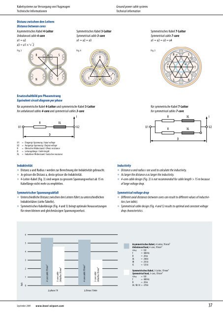
Distanz zwischen den Leitern<br />
Distance between cores<br />
Asymmetrisches Kabel 4-Leiter<br />
Unbalanced cable 4-core<br />
a1 = a2<br />
a3 = a1 × ��2<br />
Ersatzschaltbild pro Phasenstrang<br />
Equivalent circuit diagram per phase<br />
Symmetrisches Kabel 3-Leiter<br />
Symmetrical cable 3-core<br />
a1 = a2 = a3<br />
Fig. 3 Fig. 4 Fig. 5<br />
R<br />
a1 S<br />
für asymmetrische Kabel 4-Leiter und symmetrische Kabel 3-Leiter<br />
for unbalanced cables 4-core and symmetrical cables 3-core<br />
U1<br />
U1 = Eingangs-Spannung / Input voltage<br />
U2 = Ausgangs-Spannung / Output voltage<br />
R = Ohmscher Widerstand / Ohmic resistance<br />
D = Leitungslänge / Cable length<br />
XL = Induktiver Widerstand / Inductive reactance<br />
Induktivität<br />
� Distanz a und Radius r werden zur Berechnung der Induktivität gebraucht.<br />
� Je grösser die Distanz a, desto grösser die Induktivität.<br />
� 4-Leiter-Kabel (Fig. 3) sind wegen zu grossem Spannungsverlust ab 15 m<br />
Kabellänge nicht mehr zu empfehlen.<br />
Symmetrischer Spannungsabfall<br />
� Unterschiedliche Distanz zwischen den Leitern führt zu unterschiedlichen<br />
Induktivitäten (siehe Tabelle).<br />
� Symmetrisches Kabeldesign (Fig. 4 und 5) bringt optimale Voraussetzungen<br />
für einen kleinen und gleichmässigen Spannungsverlust.<br />
Volt<br />
6<br />
5<br />
4<br />
3<br />
2<br />
1<br />
0<br />
N<br />
September 2009 www.leoni-airport.com<br />
a3<br />
R XL<br />
4-core cable 70 mm²<br />
D<br />
T<br />
a2<br />
3-core cable<br />
Deltaflex 70 mm²<br />
r<br />
I<br />
U2<br />
4-core cable 70 mm²<br />
T<br />
a1<br />
3-core cable<br />
Deltaflex 70 mm²<br />
� phase / N � Umax / Umin<br />
R<br />
a3<br />
a2<br />
S<br />
r<br />
<strong>Ground</strong> power cable systems<br />
Technical information<br />
U1<br />
Symmetrisches Kabel 7-Leiter<br />
Symmetrical cable 7-core<br />
a1 = a2 = a3 = a4<br />
für symmetrische Kabel 7-Leiter<br />
for symmetrical cables 7-core<br />
R XL<br />
R XL<br />
Inductivity<br />
� Distance a and radius r are used to calculate the inductivity.<br />
� As larger the distance a as larger the inductivity.<br />
� 4-core cable design (Fig. 3) is not recommended for cable length > 15 m because<br />
of large voltage drop.<br />
Symmetrical voltage drop<br />
� Different axial distances between cores can result to different values of inductivities<br />
(see table).<br />
� Symmetrical cable design (Fig. 4 and 5) results to optimal and constant voltage<br />
drop characteristics.<br />
Asymmetrisches Kabel, 4-Leiter, 70 mm²<br />
Unbalanced load, 4-core, 70 mm²<br />
cos� = 0,8<br />
f = <strong>400</strong> <strong>Hz</strong><br />
D = 20 m<br />
IA = 240 A<br />
IB = 255 A<br />
IC = 125 A<br />
Symmetrisches Kabel, 3-Leiter, 70 mm²<br />
Symmetrical load, 3-core, 70 mm²<br />
cos� = 0,8<br />
f = <strong>400</strong> <strong>Hz</strong><br />
D = 20 m<br />
IA / IB / IC = 270 A<br />
T<br />
R<br />
S<br />
a1<br />
a2 a4<br />
D<br />
S<br />
R<br />
a3<br />
T<br />
I<br />
U2<br />
37