- Page 1 and 2:
Service and usage information for W
- Page 3 and 4:
Table of Contents 1. Introduction .
- Page 5 and 6:
3.3.2.1. Configuring IP filter ....
- Page 7 and 8:
1. Introduction The ET-7000/PET-700
- Page 9 and 10:
1.1.2. ET-7000/PET-7000 Module Nami
- Page 11 and 12:
More information about PET-7000 The
- Page 13 and 14:
� Communication Security Account
- Page 15 and 16:
1.3. Specification 1.3.1. System Sp
- Page 17 and 18:
1.3.2. I/O Specification 1.3.2.1. E
- Page 19 and 20:
1.3.2.2. ET-7044/PET-7044 ET-7000/P
- Page 21 and 22:
1.3.2.3. ET-7050 Digital Input ET-7
- Page 23 and 24:
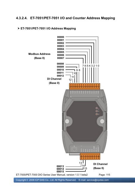
1.3.2.4. ET-7051/PET-7051 ET-7000/P
- Page 25 and 26:
1.3.2.5. ET-7052/PET-7052 ET-7000/P
- Page 27 and 28:
1.3.2.6. ET-7053 ET-7000/PET-7000 D
- Page 29 and 30:
1.3.2.7. ET-7060/PET-7060 ET-7000/P
- Page 31 and 32:
1.3.2.8. ET-7065/PET-7065 ET-7000/P
- Page 33 and 34:
1.3.2.9. ET-7066 ET-7000/PET-7000 D
- Page 35 and 36:
1.3.2.10. ET-7067/PET-7067 ET-7000/
- Page 37 and 38:
1.4. Wiring Connection 1.4.1. ET-70
- Page 39 and 40:
1.4.4. ET-7053 1.4.5. ET-7060/PET-7
- Page 41 and 42:
1.4.8. ET-7067/PET-7067 ET-7000/PET
- Page 43 and 44:
� J1 Connector Depending on the t
- Page 45 and 46:
1.5.2. Back Panel The ET-7000/PET-7
- Page 47 and 48:
1.6. Dimensions All dimensions are
- Page 49 and 50:
2. Getting Started If you are a new
- Page 51 and 52:
2.2. Configuring the Boot Mode The
- Page 53 and 54:
2.4. Installing the MiniOS7 Utility
- Page 55 and 56:
Step 2: Press “F12” or choose
- Page 57 and 58:
Step 6: Reboot the module and then
- Page 59 and 60:
You can verify that it has been ins
- Page 61 and 62:
Step 3: Fill out the User name and
- Page 63 and 64: 3.1. Overview The Overview links to
- Page 65 and 66: 3.2. Configuration All items below
- Page 67 and 68: 3.2.1.1. Configure the Network Sett
- Page 69 and 70: 3.2.1.2. Check the software informa
- Page 71 and 72: 3.2.2.1. Configure the Module Infor
- Page 73 and 74: � More Information URL: The URL o
- Page 75 and 76: 3.2.2.3. Reset All Settings to Defa
- Page 77 and 78: Module I/O Settings The default set
- Page 79 and 80: 3.2.3. Module I/O Settings The Comm
- Page 81 and 82: 3.3.1. Account Management The Basic
- Page 83 and 84: 3.3.1.2. Load the factory default u
- Page 85 and 86: 3.3.2.1. Configuring IP filter The
- Page 87 and 88: 3.4. Web HMI All items below are lo
- Page 89 and 90: 3.4.2. Web Edit The Web Editing pag
- Page 91 and 92: Below is an example of how to creat
- Page 93 and 94: Step 3: Set the page name and selec
- Page 95 and 96: Step 8: Add a DO for writing Motor1
- Page 97 and 98: 3.5. Pair Connection The Pair Conne
- Page 99 and 100: 4. Modbus Applications The ET-7000/
- Page 101 and 102: 4.2. Modbus Message Structure Modbu
- Page 103 and 104: 4.2.2. Function Codes The second by
- Page 105 and 106: � (4xxxx) AO address Begin addres
- Page 107 and 108: 4.3.2.1. ET-7042 I/O Address Mappin
- Page 109 and 110: 4.3.2.2. ET-7044/PET-7044 I/O Addre
- Page 111 and 112: 4.3.2.3. ET-7050 I/O and Counter Ad
- Page 113: Detailed Modbus Address Table for E
- Page 117 and 118: Detailed Modbus Address Table for E
- Page 119 and 120: 4.3.2.5. ET-7052/PET-7052 I/O and C
- Page 121 and 122: Detailed Modbus Address Table for E
- Page 123 and 124: 4.3.2.6. ET-7053 I/O and Counter Ad
- Page 125 and 126: Detailed Modbus Address Table for E
- Page 127 and 128: 4.3.2.7. ET-7060/PET-7060 I/O and C
- Page 129 and 130: Detailed Modbus Address Table for E
- Page 131 and 132: 4.3.2.8. ET-7065/PET-7065 I/O and C
- Page 133 and 134: Detailed Modbus Address Table for E
- Page 135 and 136: 4.3.2.9. ET-7066/PET-7066 I/O Addre
- Page 137 and 138: 4.3.2.10. ET-7067/PET-7067 I/O Addr
- Page 139 and 140: 5. MiniOS7 Utility Tool MiniOS7 Uti
- Page 141 and 142: Step 4: The connection has ready be
- Page 143 and 144: After executing the Quick Firmware
- Page 145 and 146: Step 2: Turn the switch to “Init
- Page 147 and 148: Step 6: Select the latest version o
- Page 149 and 150: 5.4. Uploading the ET-7000/PET-7000
- Page 151 and 152: Step 4: Choose “Erase Disk” fro
- Page 153 and 154: After confirming the command, you j
- Page 155 and 156: 6.2. OPC Server OPC (OLE for Proces
- Page 157 and 158: 6.3.1. InduSoft InduSoft Web Studio
- Page 159 and 160: 6.3.3. iFix The document containing
- Page 161 and 162: Appendix B. Modbus Application Note
- Page 163 and 164: B.3. Safe Value If the time of the
- Page 165 and 166:
Address 40296 to 40327 records the
- Page 167 and 168:
� Momentary Alarm The alarm statu
- Page 169 and 170:
B.5. AI High/Low Latch The address
- Page 171 and 172:
Average value of all AI channel The
- Page 173:
Appendix C. Troubleshooting A numbe