Alphatronic 2000 PCS - MAN Diesel & Turbo
Alphatronic 2000 PCS - MAN Diesel & Turbo
Alphatronic 2000 PCS - MAN Diesel & Turbo

Create successful ePaper yourself
Turn your PDF publications into a flip-book with our unique Google optimized e-Paper software.
<strong>Alphatronic</strong> <strong>2000</strong> <strong>PCS</strong><br />
Propulsion Control System
Contents<br />
Introduction .................................................................................................5<br />
Ship’s Propulsion Power – controlled by <strong>Alphatronic</strong> .....................................5<br />
Evolution of control .................................................................................5<br />
Accumulated expertise............................................................................5<br />
Control is crucial .....................................................................................6<br />
Inherent advantages ...............................................................................6<br />
The engine and propeller manufacturer’s advantage ................................6<br />
<strong>Alphatronic</strong> Propulsion Control System – General ..........................................7<br />
Plant configurations ................................................................................7<br />
Included in the system ............................................................................7<br />
Engine equipment ...................................................................................7<br />
Primary control function ..........................................................................8<br />
In case of emergency ..............................................................................8<br />
Load control ...........................................................................................8<br />
Control lever orders and commands ........................................................9<br />
Load program .........................................................................................9<br />
Charge air limit curves ............................................................................9<br />
Modes of Operation .................................................................................. 10<br />
Combined mode ................................................................................... 10<br />
Constant speed mode .......................................................................... 10<br />
Separate mode ..................................................................................... 10<br />
Bridge Main Manoeuvre Panels .................................................................. 10<br />
Bridge wing manoeuvre panels ............................................................. 11<br />
Control levers in the manoeuvring handle panels ................................... 11<br />
Electrical shaft system .......................................................................... 11<br />
Telegraph system integrated in manoeuvre panels ................................. 12<br />
Propulsion Control Panel ....................................................................... 12<br />
Interfaces to External Systems.................................................................... 13<br />
Voyage Data Recorder .......................................................................... 13<br />
Power Take Home (PTH) ....................................................................... 13<br />
Power Boost......................................................................................... 14<br />
Power Take Off ..................................................................................... 14<br />
Gear and clutches ................................................................................ 16<br />
Safety system ....................................................................................... 17<br />
Engine .................................................................................................. 18<br />
Joystick / coordinated control system ................................................... 21<br />
Main Cabinet.............................................................................................. 22<br />
Installation.................................................................................................. 22<br />
Cable Plans ............................................................................................... 26<br />
Commissioning ..................................................................................... 27<br />
Instruction Manual ...................................................................................... 27<br />
<strong>MAN</strong> <strong>Diesel</strong> & <strong>Turbo</strong>, Frederikshavn, Denmark<br />
<strong>Alphatronic</strong> <strong>2000</strong> <strong>PCS</strong> Propulsion Control System<br />
3
<strong>Alphatronic</strong> <strong>2000</strong> <strong>PCS</strong><br />
Propulsion Control System<br />
Introduction<br />
The purpose of this Product Informa-<br />
tion brochure is to act as a guideline<br />
during project planning and lay out<br />
of the <strong>Alphatronic</strong> Propulsion Con-<br />
trol Systems. The brochure gives a<br />
description of the system in general,<br />
standard control elements and options<br />
available for tailoring a remote control<br />
system for the individual vessel and its<br />
propulsion system configuration, oper-<br />
ating modes and manoeuvre stations.<br />
Our product range is constantly under<br />
review, being developed and improved<br />
according to present and future re-<br />
quirements and conditions. We there-<br />
fore reserve the right to make changes<br />
to the technical specifications and data<br />
without prior notice.<br />
<strong>Alphatronic</strong> Propulsion Control Sys-<br />
tems are usually specified together with<br />
<strong>MAN</strong> <strong>Diesel</strong> & <strong>Turbo</strong>’s Alpha Controlla-<br />
ble Pitch Propellers.<br />
The propeller programme may be stud-<br />
ied in separate literature.<br />
Ship’s Propulsion Power – controlled<br />
by <strong>Alphatronic</strong><br />
<strong>MAN</strong> <strong>Diesel</strong> & <strong>Turbo</strong>, launched the first<br />
CP propeller as part of a propulsion<br />
system in 1902. A complete package<br />
including engine, clutch, shafting and<br />
propeller. A package where all control<br />
and manoeuvre actions were carried<br />
out, in accordance with the standards<br />
of that time, locally by hands–on.<br />
Evolution of control<br />
In view of the following years of de-<br />
velopment, not only in the physical<br />
dimensions of the ships, but also in<br />
the propulsion equipment itself, – the<br />
control and manoeuvre actions shifted<br />
from local to remote by means of dif-<br />
ferent intermediates. These interme-<br />
diates developed from mechanical<br />
push/pull rod systems, flexible cable<br />
systems, pneumatic systems up till<br />
today’s electronic systems. Year by<br />
year, both the operator and the equip-<br />
ment itself required more and more<br />
sophisticated control systems for<br />
economical cruising at various operat-<br />
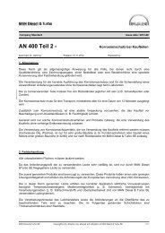
Fig. 1: Two–stoke propulsion package (8S50MC�C engine, tunnel gear, VBS1680 propeller)<br />
ing modes, engine load sharing, redun-<br />
dant propulsion using PTI/PTH etc.<br />
The latest version of the <strong>Alphatronic</strong><br />
system described in this material is type<br />
<strong>Alphatronic</strong> <strong>2000</strong> <strong>PCS</strong>. <strong>PCS</strong> is an ab-<br />
breviation of Propulsion Control System.<br />
Accumulated expertise<br />
Since 1902, more than 7.000 propel-<br />
lers and propulsion packages have<br />
gone into service – operated by various<br />
types of <strong>MAN</strong> <strong>Diesel</strong> & <strong>Turbo</strong> control<br />
systems. Today’s standard for <strong>MAN</strong><br />
<strong>Diesel</strong> & <strong>Turbo</strong>’s Alpha CP propellers<br />
and propulsion packages is the well–<br />
proven electronic remote control sys-<br />
tem, <strong>Alphatronic</strong>.<br />
Since its introduction in 1982, more<br />
than 1400 systems have been delivered<br />
for a wide range of propulsion plant<br />
combinations with two-stroke engines<br />
and propellers, four-stroke engines, re-<br />
duction gearboxes and propellers for<br />
the output range up to 30,000 kW per<br />
propeller.<br />
<strong>Alphatronic</strong> <strong>2000</strong> <strong>PCS</strong> Propulsion Control System<br />
5
Control is crucial<br />
In the process of projecting and esti-<br />
mating propulsion systems, the asso-<br />
ciated control system is a ‘soft’ item<br />
frequently handled with less attention.<br />
The propulsion control system is often<br />
regarded as a necessary auxiliary<br />
element that just follows the primary<br />
propulsion elements. Fuel consump-<br />
tion, emision levels and propulsion<br />
efficiency of the ‘hard’ engine and<br />
propeller elements are, however,<br />
undermined – without the correct<br />
matching and performing control<br />
system!<br />
Inherent advantages<br />
A tailored <strong>Alphatronic</strong> control system<br />
ensures:<br />
Safe control of the propulsion plant<br />
and reliable manoeuvring of the ship<br />
Economic operation due to optimised<br />
engine/propeller load control<br />
Quick system response and efficient<br />
CP propeller manoeuvrability<br />
6 <strong>Alphatronic</strong> <strong>2000</strong> <strong>PCS</strong> Propulsion Control System<br />
Load changes controlled in such a<br />
way that the governor always keeps<br />
the engine speed within the range re-<br />
quired, and thus prevents black-out<br />
during shaft alternator operation<br />
Good long term engine performance<br />
due to overload protection<br />
Thermal protection of the engine via<br />
controlled running–up programmes<br />
Environmental friendliness due to<br />
balanced manoeuvring dynamics<br />
during acceleration with minimal<br />
smoke emission<br />
Flexibility and individual customiza-<br />
tion due to modular system principles<br />
Project support, simple installation<br />
procedures and safe commissioning<br />
Minimal service and maintenance<br />
requirements<br />
User–friendly operator functions due<br />
to logic and ergonomic design of<br />
control panels<br />
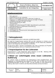
Fig. 2: Four–stroke propulsion package (6L48/60B engine, reduction gear, VBS1460 propeller)<br />
Overall system reliability and durability<br />
Type approval by all major Classifica-<br />
tion Societies<br />
The engine and propeller manufac-<br />
turer’s advantage<br />
In general, the control system acts as<br />
the central propulsion package ele-<br />
ment, being in charge of the remaining<br />
propulsion package elements, their co-<br />
herence and their interaction with one<br />
another.<br />
The experience inherent in the Al-<br />
phatronic systems, accumulated during<br />
25 years of service – is full knowledge of:<br />
All propulsion package elements<br />
Two-stroke and four-stroke engine<br />
designs<br />
CP propeller designs<br />
Overall operating economy, long<br />
term performance, load characteris-<br />
tics and system dynamics<br />
– and that makes all the difference.
<strong>Alphatronic</strong> Propulsion Control<br />
System – General<br />
With this electronic propulsion control<br />
system it is possible for the navigator<br />
to manoeuvre the ship from the bridge.<br />
The navigator may operate the control<br />
system without consideration for the<br />
engine load condition, since the system<br />
ensures automatic engine overload pro-<br />
tection.<br />
When desired, the manoeuvre responsi-<br />
bility may be transferred from the main<br />
bridge panel to the bridge wing panels<br />
or to the control room panel.<br />
Plant configurations<br />
The <strong>Alphatronic</strong> propulsion control sys-<br />
tem is designed for propulsion plants<br />
consisting of a CP propeller and a two–<br />
stoke or a four–stroke engine in several<br />
plant configurations. From the relatively<br />
simple plants shown in fig.1 and fig. 2 to<br />
many different and more complex con-<br />
figurations, e.g.:<br />
Multiple engines on one gearbox<br />
Multiple propeller plants<br />
Redundant propulsion solutions with<br />
Power Take-Home (PTH) using a com-<br />
bined shaft generator / shaft motor<br />
Interface to dynamic positioning (DP)<br />
and joystick system.<br />
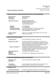
Included in the system<br />
A typical system consists of the fol-<br />
lowing main components shown in the<br />
principle diagram fig. 3:<br />
1 Manoeuvre panels for main bridge<br />
(centre and wings)<br />
2 Manoeuvre panel for engine control<br />
room<br />
3 Main cabinet including the process<br />
computer<br />
4 Propeller servo electronics (closed<br />
loop amplifier and propeller indication<br />
electronics)<br />
1. Bridge wing 1. Main Bridge<br />
2. Engine control room<br />
Fig. 3: Control system structure<br />
4. Propeller<br />
servo electronics<br />
Engine equipment<br />
The governor and the safety system<br />
are considered part of the engine and<br />
therefore not a part of the propulsion<br />
control system. Nevertheless, there is<br />
a close connection between these. For<br />
details of interfacing engine, governor<br />
and safety system, please refer to the<br />
interface descriptions on page 13.<br />
3. Main cabinet<br />
1. Bridge wing<br />
<strong>Alphatronic</strong> <strong>2000</strong> <strong>PCS</strong> Propulsion Control System<br />
7
Primary control function<br />
The manoeuvre panels are fitted with<br />
manoeuvre levers for controlling the<br />
propeller speed and pitch. The lever on<br />
the bridge centre panel and the lever on<br />
the ECR panel have individual potenti-<br />
ometers connected to the main cabinet.<br />
Depending on the chosen mode of op-<br />
eration, these lever signals will be used<br />
for setting the engine speed and the<br />
propeller pitch accordingly.<br />
An electric speed setting signal is trans-<br />
mitted from the <strong>PCS</strong> main cabinet to<br />
the engine governor. If the engine has a<br />
governor with pneumatic speed setting,<br />
the electric speed order is converted<br />
into a pressure using an E/P–converter.<br />
The propeller pitch is controlled by two<br />
solenoid valves in the hydraulic system.<br />
The electronic servo unit controls the<br />
solenoid valves for ’ahead’ and ’astern’<br />
pitch changes by comparing actual<br />
pitch and set point. Actual propeller<br />
pitch is measured by two transmitters.<br />
One transmitter is used for indication<br />
of the actual position of the propeller.<br />
The other transmitter gives the feed-<br />
back signal to the electronic servo unit.<br />
In case of emergency<br />
If the propulsion control system is out<br />
of service, the propulsion plant may still<br />
be operated from the bridge using the<br />
back-up system. The back-up system<br />
is independent of the main control sys-<br />
tem, although it is operated from the<br />
same lever on the bridge.<br />
Selection of back-up will set the gov-<br />
ernor to a fixed speed (normally corre-<br />
sponding to the nominal shaft generator<br />
speed) and set the propeller pitch corre-<br />
sponding to the present thrust. Change<br />
8 <strong>Alphatronic</strong> <strong>2000</strong> <strong>PCS</strong> Propulsion Control System<br />
Load diagram<br />
Power [%]<br />
100<br />
90<br />
80<br />
70<br />
60<br />
50<br />
40<br />
30<br />
20<br />
10<br />
0<br />
1<br />
2<br />
5<br />
60 65 70 75 80 85 90 95 100<br />
Theoretical Propeller Curve<br />
3<br />
1<br />
Combinator Curve<br />
2 100% MEP<br />
5 50% MEP<br />
3<br />
Load Limit<br />
Fig. 4: General load diagram<br />
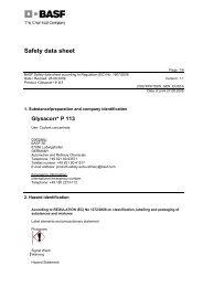
Pitch and engine speed slew rates<br />
Propeller pitch [%]<br />
100<br />
80<br />
60<br />
40<br />
20<br />
0<br />
-20<br />
-40<br />
-60<br />
-80<br />
-100<br />
4<br />
6<br />
Zero Thrust Curve<br />
-20 0 20 40 60<br />
6<br />
4<br />
time [sec.]<br />
Normal pitch rate ahead Pitch rate at crash stop<br />
Speed [%]<br />
Normal engine speed rate Engine speed rate at crash stop<br />
Normal pitch rate astern<br />
Fig. 5: Control lever slew rate for propeller pitch command<br />
between normal control and back-up<br />
control will thus not change the actual<br />
propeller thrust.<br />
Load control<br />
The control system uses the propeller<br />
pitch and engine speed as controlling
parameters. Fuel pump index, engine<br />
speed and charge air pressure are<br />
used as feedback. The engine load is<br />
kept within the limits as specified by the<br />
load limit curve of the engine. The load<br />
curve for combined mode is adjusted<br />
according to the specific engine and<br />
propulsion equipment – taking fuel oil<br />
consumption, propeller efficiency and<br />
manoeuvrability into consideration in<br />
order to obtain optimum overall propul-<br />
sion efficiency.<br />
Control lever orders and commands<br />
In order to allow the engine and the<br />
vessel to respond, the system is able<br />
to control the rate at which the en-<br />
gine speed and the propeller pitch is<br />
changed. The control lever orders are<br />
translated into engine speed and pro-<br />
peller pitch commands as shown in fig<br />
5. The slew rates will vary with the plant<br />
configurations.<br />
In addition to these slew rates, pitch will<br />
be dynamically limited by the load pro-<br />
gram and the actual charge air pressure.<br />
Load program<br />
A running-up load program is included<br />
for the engine as illustrated in the exam-<br />
ple in fig 6. In the figure, both the nor-<br />
mal load-up of the engine as well as the<br />
load-up during cancelled load restric-<br />
tions are illustrated.<br />
Charge air limit curves<br />
In order to allow the engine to take up<br />
load as fast as possible without gener-<br />
ating smoke, the control system uses<br />
a measurement of the actual charge<br />
air pressure to limit the engine fuel in-<br />
dex (by not increasing the pitch before<br />
sufficient charge air is available). See<br />
change air limit curves in fig. 7.<br />
Running up load program<br />
Engine load limit [%]<br />
120<br />
100<br />
80<br />
60<br />
40<br />
20<br />
0<br />
0 1 2 3 4 5 6 7 8 9 10 11 12<br />
Run up, load restrictions cancelled<br />
Run up, normal<br />
Fig. 6: Running up load program<br />
Charge air limit curves<br />
Fuel pump index [%]<br />
120<br />
100<br />
80<br />
60<br />
40<br />
20<br />
0<br />
Running up time [min]<br />
0 1 2 3 4<br />
Charge air limit, load restrictions cancelled<br />
Charge air limit curve, normal<br />
Fig. 7: Charge air limit curves<br />
Charge air pressure [Bar]<br />
<strong>Alphatronic</strong> <strong>2000</strong> <strong>PCS</strong> Propulsion Control System<br />
9
Modes of Operation<br />
The propulsion plant can be operated in<br />
three different modes.<br />
Combined mode<br />
In combined mode, both pitch and<br />
speed are controlled by using the lever.<br />
This is done according to the combi-<br />
nator curve as shown in fig 8, ensur-<br />
ing optimum operation and propulsion<br />
economy – considering propeller effi-<br />
ciency, manoeuvrability and minimized<br />
fuel consumption<br />
Constant speed mode<br />
When constant speed mode is select-<br />
ed, the levers in the manoeuvre pan-<br />
els will only control the propeller pitch.<br />
The speed is set to a fixed value cor-<br />
responding to the nominal speed of the<br />
shaft alternator – if any.<br />
Combinator curves<br />
100<br />
80<br />
60<br />
40<br />
20<br />
0<br />
-20<br />
-40<br />
-60<br />
-80<br />
-100<br />
-10 -8 -6 -4 -2 0 2 4 6 8 10<br />
Pitch %<br />
Engine speed %<br />
Power demand<br />
10 <strong>Alphatronic</strong> <strong>2000</strong> <strong>PCS</strong> Propulsion Control System<br />
The automatic load control is, however,<br />
still active for engine overload protec-<br />
tion. With the shaft alternator in service,<br />
the load control system can handle a<br />
crash stop order, without any risk of a<br />
black-out.<br />
Separate mode<br />
Separate mode specifies the condition<br />
where pitch and speed can be control-<br />
led individually. The pitch is adjusted<br />
using the lever and the engine speed is<br />
adjusted using the Propulsion Control<br />
Panel.<br />
Bridge Main Manoeuvre Panels<br />
As a minimum the propulsion control<br />
system will always include a main bridge<br />
panel per engine/propeller, please refer<br />
to fig. 9.<br />
Handle position<br />
Fig. 8: Combined mode – combined pitch/speed order and engine load curve for a two�stroke<br />
propulsion package<br />
The main manoeuvre panel consists of<br />
three individual panels:<br />
Propeller Instrument Panel, PIP Indi-<br />
cating propeller speed and propel-<br />
ler pitch. These two instruments are<br />
working independently of the remote<br />
control system. The light dimmer is<br />
operating on both PIP and MHP.<br />
Manoeuvring Handle Panel, MHP<br />
Incorporates the control lever and<br />
normally also an emergency stop<br />
push-button, a push-button for<br />
selection of back-up control and<br />
push-button /indicator for selection<br />
of control position.<br />
Propulsion Control Panel, PCP<br />
The primary functions of the panel<br />
are selection of control position and<br />
operating mode. In addition, certain<br />
safety functions and special machin-<br />
ery operation, including alarm lists,<br />
are available.<br />
All three panels have the standard in-<br />
strument sizes 144 mm x 288 mm for<br />
convenient installation together with<br />
other standard instruments in the bridge<br />
and ECR consoles.
Bridge wing manoeuvre panels<br />
Typically, two bridge wing panels are<br />
supplied. Wing panels are available in<br />
indoor and outdoor versions. Indoor<br />
wing panels may optionally be equipped<br />
with a Propulsion Control Panel if de-<br />
sired. Please refer to figures 10 and 11.<br />
Control levers in the manoeuvring<br />
handle panels<br />
Fig. 12 shows a typical control lever<br />
configuration. The control lever in the<br />
bridge main manoeuvre panel is con-<br />
nected to the main cabinet of the re-<br />
mote control system.<br />
As standard the engine control room<br />
(ECR) is equipped with a similar control<br />
lever. Optionally the system can be de-<br />
livered without equipment in the engine<br />
control room.<br />
The control lever in the bridge main ma-<br />
noeuvre panel and the control lever in<br />
the ECR are independent of each other.<br />
Electrical shaft system<br />
Ships with bridge wing control are<br />
equipped with an electrical shaft sys-<br />
tem interconnecting the bridge main<br />
and bridge wing control levers.<br />
The electric shaft system is a so-called<br />
synchronizing system, in which the<br />
non-active control levers are following<br />
the active control lever. I.e. when the<br />
bridge main manoeuvre panel is select-<br />
ed as “IN CONTROL”, the two bridge<br />
wing levers will automatically follow the<br />
bridge main control lever.<br />
This system design secures that the<br />
handle chosen to be “IN CONTROL”<br />
will act as a master and the other han-<br />
dles on the bridge will follow its posi-<br />
Fig. 9: Bridge manoeuvre panel – main bridge<br />
Fig. 10: Bridge manoeuvre panel – bridge wing indoor<br />
Fig. 11: Bridge manoeuvre panel – bridge wing outdoor<br />
<strong>Alphatronic</strong> <strong>2000</strong> <strong>PCS</strong> Propulsion Control System<br />
11
Bridge Wing<br />
tion. This will avoid any synchronizing of<br />
handles at the time of changing control<br />
position on the bridge.<br />
The electrical shaft standard solution<br />
can handle three panels on the bridge.<br />
However additional manoeuvring pan-<br />
els may be added, providing for typi-<br />
cally also an aft bridge. A maximum of<br />
16 panels can be controlled in one elec-<br />
trical shaft system.<br />
Telegraph system integrated in ma-<br />
noeuvre panels<br />
Main Control Station<br />
Bridge Center Bridge Wing<br />
Pitch Setpoint, Back-up Control<br />
Setpoint, Bridge<br />
Propeller Pitch<br />
Closed Loop<br />
Control Box<br />
Fig. 12: A configuration of manoeuvre handles<br />
Optionally, the levers at the main bridge<br />
and in the ECR may be equipped with a<br />
telegraph dial and one additional point-<br />
er. The additional pointer on the bridge<br />
always shows the position of the cor-<br />
responding telegraph lever, being either<br />
the lever in the ECR or in the engine<br />
room depending on the actual control<br />
position. When an active lever is moved,<br />
Setpoint, ECR<br />
Remote Control<br />
System<br />
Main Cabinet<br />
12 <strong>Alphatronic</strong> <strong>2000</strong> <strong>PCS</strong> Propulsion Control System<br />
Electric Shaft<br />
Control Box<br />
Pitch Setpoint, RCS<br />
BACK UP<br />
CONTROL<br />
ON/OFF<br />
FINISH<br />
WITH<br />
ENGINE<br />
FULL<br />
HALF<br />
SLOW<br />
DEAD<br />
SLOW<br />
STOP<br />
DEAD<br />
SLOW<br />
SLOW<br />
HALF<br />
FULL<br />
STAND<br />
BY<br />
IN<br />
CONTROL<br />
EMERGENCY<br />
STOP<br />
TAKE<br />
CONTROL<br />
normally the bridge lever, the telegraph<br />
bells will sound until the reply pointer<br />
has the same position as acknowledge-<br />
ment by the machinery crew that the<br />
requested order has been understood.<br />
Please refer to fig. 13 showing the main<br />
bridge and ECR manoeuvring panels<br />
with integrated telegraph function.<br />
The telegraph function is a means of<br />
communication between the bridge and<br />
the engine area. It is normally only used<br />
in case of problems with the remote con-<br />
trol system, and thus it is electrically in-<br />
dependent of the remote control system.<br />
In addition to the function of commu-<br />
nicating manoeuvring orders between<br />
bridge and engine area, the telegraph<br />
system will normally also have the two<br />
additional communication functions for<br />
Finished With Engine (FWE) and Stand<br />
By included. Activating the push but-<br />
FINISH<br />
WITH<br />
ENGINE<br />
FULL<br />
HALF<br />
SLOW<br />
DEAD<br />
SLOW<br />
STOP<br />
DEAD<br />
SLOW<br />
SLOW<br />
HALF<br />
FULL<br />
STAND<br />
BY<br />
TELE-<br />
GRAPH<br />
ON/OFF<br />
EMERGENCY<br />
STOP<br />
ON<br />
SERVICE<br />
Fig. 13: Main bridge and ECR manoeuvring panels with integrated telegraph function<br />
ton FWE on the bridge will start the<br />
telegraph bells until the corresponding<br />
push button is acknowledged in the<br />
machinery area. The same principle ap-<br />
plies for the Stand By function.
l<br />
k<br />
a<br />
b<br />
Propulsion Control System <strong>Alphatronic</strong> <strong>2000</strong><br />
ALARM<br />
MAINTE-<br />
NANCE<br />
ENGINE<br />
CONTROL<br />
ROOM<br />
SEPA-<br />
RATE<br />
Fig. 14: Propulsion Control Panel<br />
Propulsion Control Panel<br />
m n<br />
OVER<br />
LOAD<br />
STOP<br />
HORN<br />
BRIDGE<br />
CONST.<br />
SPEED<br />
FAULT<br />
ACCEPT<br />
LOCAL<br />
CONTROL<br />
COMBI-<br />
NATOR<br />
Fig. 14 shows the Propulsion Control<br />
Panel. The contents of the display will<br />
vary during operation. In basic mode,<br />
the display will indicate the available<br />
power, the power demand from the<br />
active control position and the ac-<br />
tual power delivered by the engine.<br />
The last line will show the oldest<br />
unacknowledged alarm, if any.<br />
The keys and indicators of the panel<br />
have the following functions:<br />
a. Control position selection and indica-<br />
tion<br />
b. Operating mode selection and indi-<br />
cation<br />
c. Shut down indication and operation<br />
(cancel and reset)<br />
SHUT<br />
DOWN<br />
CANCEL<br />
SHUT<br />
DOWN<br />
RESET<br />
SHUT<br />
DOWN<br />
j<br />
LOAD<br />
REDUC.<br />
CANCEL<br />
LOAD<br />
REDUC.<br />
RESET<br />
LOAD.<br />
REDUC<br />
S1 S2 S3 S4<br />
LOAD<br />
RESTRICT<br />
CANCEL<br />
MACHI-<br />
NERY<br />
CONTROL<br />
i<br />
ESC ENT<br />
c d e f g<br />
d. Load reduction indication and opera-<br />
tion (cancel and reset)<br />
e. Indication of active load restrictions.<br />
May be cancelled by pushing key<br />
f. Machinery control. E.g. start and<br />
stop of engine, clutching in and out.<br />
Operation via softkeys S1 through S4<br />
g. Navigation keys for moving around in<br />
lists and changing parameters<br />
h. Collective dimming of keys, indica-<br />
tors and display in panel<br />
i. Softkeys for operation. Actual func-<br />
tion will be explained in the display<br />
above the key<br />
j. Keys for stopping the horn and ac-<br />
knowledge of alarms<br />
k. Maintenance key Gives access to<br />
alarm lists and advanced features<br />
and adjustments<br />
l. Alarm lamp. Flashing when new<br />
alarms arrive<br />
m. Lamp for indication of engine overload.<br />
Used during back-up control where no<br />
load control is in function<br />
n. Lamp for indication of internal faults<br />
in the propulsion control panel itself<br />
Generally, operation of the plant will<br />
only be possible from the active control<br />
location, i.e. bridge or engine control<br />
room. However, display facilities are al-<br />
ways open at all panels.<br />
<strong>Alphatronic</strong> <strong>2000</strong> <strong>PCS</strong> Propulsion Control System<br />
h<br />
13
Interfaces to External Systems<br />
The <strong>Alphatronic</strong> remote control system<br />
can be interfaced with a variety of exter-<br />
nal systems. Included in this document,<br />
there is a description of a number of of-<br />
ten used interfaces that have proven to<br />
work. For each of the below described<br />
interfaces, there is a more comprehen-<br />
sive description available.<br />
Voyage Data Recorder<br />
The <strong>Alphatronic</strong> propulsion control sys-<br />
tem is equipped with a standard inter-<br />
face for a voyage data recorder (VDR)<br />
following the standard IEC 61996 as re-<br />
quired by the IMO. The electrical inter-<br />
face is done according to IEC 61162-1<br />
.<br />
Power Take Home (PTH)<br />
For a number of vessels, e.g. chemical<br />
tankers, it is desired to have a possibil-<br />
ity of alternative propulsion power if the<br />
main engine is not available. Such al-<br />
ternative propulsion can be established<br />
by using the shaft alternator as a shaft<br />
motor. A number of prerequisites must<br />
be considered. It must be possible to<br />
disengage the main engine before the<br />
shaft motor can be engaged, and there<br />
must be a way of bringing the shaft mo-<br />
tor from stand still to nominal speed.<br />
As a rule of thumb, there must be elec-<br />
trical power available corresponding to<br />
at least 25 - 30 % of the main engine<br />
power. Preferably, the combined PTO/<br />
PTI could be connected via a two speed<br />
gear. This will reduce the size of the re-<br />
quired PTI and the associated equip-<br />
ment for starting the PTI from stand still.<br />
Fig. 15 shows the interface for a PTH<br />
solution.<br />
14 <strong>Alphatronic</strong> <strong>2000</strong> <strong>PCS</strong> Propulsion Control System<br />
Power Boost<br />
This feature may be relevant for short<br />
term boosting of the propulsion power.<br />
It is necessary that the gear and the<br />
propeller are designed for the total<br />
power of diesel engine and shaft motor.<br />
It is necessary that the amount of power<br />
supplied by the shaft motor is controlled<br />
by the ships power management sys-<br />
tem. No electrical interface is thus nec-<br />
essary to the remote control system.<br />
Power Take Off<br />
The most common type of power take<br />
off (PTO) is a shaft generator running at<br />
a fixed frequency. However other types<br />
of shaft generators exist, which are able<br />
to work at variable engine speed.<br />
ET4816<br />
Remote Control System<br />
type AT<strong>2000</strong> <strong>PCS</strong><br />
EC4817, PTI start command<br />
Closed contact = start<br />
(2 sec. pulse)<br />
EC4818, PTI running<br />
Closed contact = running above<br />
95% of nominal speed<br />
EC4819, PTI stop command<br />
Closed contact = stop<br />
(2 sec. pulse)<br />
SE2745<br />
Fig. 15: Interface for a PTH solution<br />
f<br />
n<br />
Power Management System /<br />
Main Switch Board<br />
El-motor load<br />
4 - 20 mA<br />
Galvanically separated<br />
Gear<br />
PTI rpm pick-up<br />
- Number of pulses<br />
per revolution: 4 - 999<br />
- Type: PNP or NPN
Remote Control System<br />
type AT<strong>2000</strong> <strong>PCS</strong><br />
EC4811, PTO ready<br />
Closed contact = Engine running<br />
in Constant Speed mode and within<br />
the nominal rpm range.<br />
EC4813<br />
PTO out of service request<br />
Closed contact = request start of<br />
<strong>Diesel</strong> generator to take over load.<br />
Always required for two-stroke engines.<br />
Fig 16: Interface for a PTO solution<br />
MSB / SG (PTO)<br />
ET4810<br />
Shaft Generator breaker closed<br />
Closed contact = breaker closed<br />
ECS4824<br />
PTO in service request<br />
Closed contact (pulse) = request<br />
Will select Constant Speed mode<br />
in <strong>PCS</strong><br />
ECS4825<br />
PTO out of service request<br />
Closed contact (pulse) = request<br />
Will select Constant Speed mode<br />
in <strong>PCS</strong><br />
Optional signals. Only required if selection<br />
of constant speed has to be done from<br />
the Power Management System<br />
ECS4812A Increase RPM<br />
Closed contact (pulse) = increase<br />
ECS4812B Decrease RPM<br />
Closed contact (pulse) = decrease<br />
Optional signals. Only required if SG<br />
frequency and load control has to be done<br />
from the Power Management System<br />
Optional signal.<br />
Always required for two-stroke engines.<br />
<strong>Alphatronic</strong> <strong>2000</strong> <strong>PCS</strong> Propulsion Control System<br />
15
Remote Control System<br />
type AT<strong>2000</strong> <strong>PCS</strong><br />
Clutch engage command<br />
Closed contact = clutch-in<br />
(Pulse, active untill correct<br />
feed-back or time-out fail.<br />
Normally 10 - 20 seconds)<br />
Clutch disengage command<br />
Closed contact = clutch-out<br />
(Pulse, active untill correct<br />
feed-back or time-out fail.<br />
Normally 10 - 20 seconds)<br />
Optional. Used if available in<br />
the gear-box<br />
SE2745 Optional. Used if PTI<br />
(Power Take Home, PTH) is<br />
included in delivery<br />
PSL2231 Optional. Used if PTI<br />
(Power Take Home, PTH) is<br />
included in delivery<br />
Fig. 17: Interface for a reduction gear/clutch solution<br />
Gear and clutches<br />
When connecting a gear that is not of<br />
<strong>MAN</strong> <strong>Diesel</strong> & <strong>Turbo</strong> make, the interface<br />
shown on fig.17 applies.<br />
16 <strong>Alphatronic</strong> <strong>2000</strong> <strong>PCS</strong> Propulsion Control System<br />
+24 V<br />
0 V<br />
+24 V<br />
0 V<br />
f<br />
Clutch engaged feed-back<br />
Closed contact = clutch engaged<br />
Clutch safety disengage<br />
Closed contact = clutch out<br />
PTI rpm pick-up<br />
n<br />
P<br />
Gear<br />
Clutch(es)<br />
Solenoid data:<br />
24 V d.c. / max 24 W<br />
Diode must be mounted<br />
over coil<br />
- Number of pulses<br />
per revolution: 4 - 999<br />
- Type: PNP or NPN<br />
Gear lub. oil pressure low<br />
Closed contact = pressure low
Safety system<br />
When the engine is not of <strong>MAN</strong> or <strong>MAN</strong><br />
B&W make, neither is the safety system. Fig.<br />
18 shows the details of the necessary<br />
interface between the engine safety<br />
system and the <strong>Alphatronic</strong> propulsion<br />
control system.<br />
Remote Control System type AT<strong>2000</strong> <strong>PCS</strong><br />
ZS4735A, Shut down cancel order<br />
Contact closed at cancel<br />
ZS4736A, Shut down reset order<br />
Contact closed at reset (pulse, 2 sec.)<br />
ZS4710, Emergency stop switch<br />
Contact closed at shut down<br />
Supervision resistor: 10 kohm<br />
ZSI4710, Emergency stopped<br />
Contact closed at stopped<br />
SEH1704, Overspeed stopped<br />
Contact closed at stopped<br />
SZI4739, Non cancellable shut down<br />
Contact closed at activated sensor<br />
SZI4740, Cancellable shut down<br />
Contact closed at activated sensor<br />
SZI4737, Shut down active<br />
Contact closed at active shut down<br />
ZSI4735A, Shut down cancelled<br />
Contact closed at cancelled<br />
ZSI4748, Load reduction cancelled<br />
Contact closed at cancelled<br />
ZSI4747, Load reduction active<br />
Contact closed at active<br />
ZS4747, Automatic load reduction<br />
/ slow down request<br />
Contact closed at request<br />
Shut down system<br />
Load reduction / slow down interface Ships alarm system<br />
Fig. 18: Interface for safety system with an engine not of <strong>MAN</strong> or <strong>MAN</strong> B&W make<br />
<strong>Alphatronic</strong> <strong>2000</strong> <strong>PCS</strong> Propulsion Control System<br />
17
Engine<br />
When the engine is not of <strong>MAN</strong> or <strong>MAN</strong><br />
B&W make, the interface shown on fig.<br />
19a and 19b applies for a two-stroke<br />
engine. Fig. 20 applies for a four-stroke<br />
engine.<br />
18 <strong>Alphatronic</strong> <strong>2000</strong> <strong>PCS</strong> Propulsion Control System<br />
Remote Control System type AT<strong>2000</strong> <strong>PCS</strong><br />
ZS4714, Engine start command<br />
24 V dc, max 1A<br />
ZS4713B, Engine stop command<br />
24 V dc, max 1A<br />
ZS4716, Engine slow turn command<br />
24 V dc, max 1A<br />
ZS4701, Engine controlled locally<br />
Contact closed at local<br />
ZS4702, Engine controlled remote<br />
Contact closed at remote<br />
ZS4700A, Emergency controlled<br />
Contact closed at emergency<br />
ZS4700B, Engine governor engaged<br />
Contact closed at engaged<br />
ZS1705, Turning gear engaged<br />
Contact closed at engaged<br />
ZS1313, Main start air valve closed<br />
Contact closed at closed valve<br />
ZS1314, Start air distributor closed<br />
Contact closed at closed valve<br />
ZSI1330, Auxiliary blower running<br />
Contact closed at running<br />
PSL1321, Control air system vented<br />
Contact closed at vented<br />
PSL1322, Safety air system vented<br />
Contact closed at vented<br />
ZSH1401, Engine overload<br />
(Fuel index above 100%)<br />
Contact closed at overload<br />
PT1331B, Charge air pressure<br />
Two wire loop powered or<br />
four wire galvanically separated<br />
4 - 20 mA = 0 - 4 bar<br />
ZT1401, Fuel index<br />
Two wire loop powered or<br />
four wire galvanically separated<br />
4 - 20 mA = 0 - 110 % index<br />
SE1704A, Engine speed<br />
4 - 20 mA or 0 - 10 V = 120 % mcr<br />
Galvanically separated<br />
Fig. 19a: Interface for a two�stroke diesel engine not of <strong>MAN</strong> B&W make<br />
Two-stroke diesel engine<br />
or<br />
or
Remote Control System type AT<strong>2000</strong> <strong>PCS</strong> Engine governor<br />
SC1706A, Engine speed order<br />
4 - 20 mA = idle to 100%rpm<br />
Galvanically separated<br />
Max load resistance: 500 ohm<br />
ZS4713A, Governor stop command<br />
24 V dc, max 1A<br />
SC1708, Governor speed enable<br />
Closed contact when enabled<br />
(Only for pneumatic governor)<br />
ZI3725B, Propeller pitch<br />
feed back to governor<br />
Galvanically separated<br />
(Only for electronic governor)<br />
SC1709, Governor limits cancel<br />
Closed contact at cancel<br />
Fig. 19b: Interface for a two�stroke diesel engine not of <strong>MAN</strong> B&W make<br />
<strong>Alphatronic</strong> <strong>2000</strong> <strong>PCS</strong> Propulsion Control System<br />
19
Remote Control System type AT<strong>2000</strong> <strong>PCS</strong><br />
ZS4701, Engine controlled locally<br />
Contact closed at local<br />
ZS4702, Engine controlled remote<br />
Contact closed at remote<br />
SC4715, Engine Start Blocking<br />
Contact Open at Start Blocking<br />
Contact closed when pitch is zero<br />
and CPP servo pump is running<br />
ZSH1401, Engine overload<br />
(Fuel index above 100%)<br />
Contact closed at overload<br />
PT1331B, Charge air pressure<br />
Two wire loop powered or<br />
galvanically separated<br />
4 - 20 mA = 0 - 4 bar<br />
ZT1401, Fuel index<br />
Two wire loop powered or<br />
galvanically separated<br />
4 - 20 mA = 0 - 110 % index<br />
SE1704A, Engine speed<br />
4 - 20 mA or 0 - 10 V = 120 % mcr<br />
Galvanically separated<br />
SC1706A, Engine speed order<br />
4 - 20 mA = idle to 100%rpm<br />
Galvanically separated<br />
SC1708, Governor speed enable<br />
Closed contact when enabled<br />
(Only for pneumatic governor)<br />
ZS4714, Engine start command<br />
Contact closed at start.<br />
Pulse signal, duration 2 seconds<br />
ZS4714, Engine stop command<br />
Contact closed at stop<br />
Pulse signal, duration 2 seconds<br />
ZS4709, Engine start failure reset<br />
Contact closed at reset<br />
Pulse signal, duration 2 seconds<br />
ZS4715, Engine start blocked<br />
Contact closed at blocking<br />
20 <strong>Alphatronic</strong> <strong>2000</strong> <strong>PCS</strong> Propulsion Control System<br />
Four-stroke diesel engine<br />
or<br />
or<br />
Engine governor<br />
Max load: 500 ohm<br />
The optional signals below are used when remote start / stop via AT<strong>2000</strong>-<strong>PCS</strong> is required but<br />
start and stop sequences are carried out by the engine control system.<br />
Remote Control System type AT<strong>2000</strong> <strong>PCS</strong><br />
Fig 20: Interface for a four�stroke diesel engine not of <strong>MAN</strong> make<br />
Four-stroke diesel engine<br />
control system
Joystick / coordinated control sys-<br />
tem<br />
It is possible to transfer the control of<br />
the main propeller pitch to an external<br />
control system such as a joystick con-<br />
trol system. Control can be transferred<br />
when the manoeuvring responsibility is<br />
on the bridge, the engine is running and<br />
the propeller is engaged.<br />
During joystick control, the engine is still<br />
fully protected against overload.<br />
Fig. 21 is showing the interface be-<br />
tween an external control system and<br />
the propulsion control system.<br />
Remote Control System type AT<strong>2000</strong> <strong>PCS</strong><br />
ECS4707 Propeller ready for<br />
coordinated control<br />
Contact closed when ready<br />
ECS4708 Coordinated control<br />
system in control<br />
Contact closed when propeller is<br />
controlled by the coordinated system<br />
EC4797 Coordinated control system<br />
take-over request<br />
Pulse signal, contact closed at take-over<br />
EC4798 Coordinated control<br />
hand-over request<br />
Pulse signal, contact closed at hand-over<br />
ET4750 Propeller thrust order<br />
+/ - 10 V, galvanically separated<br />
- 10 V = 100 % thrust astern<br />
+10 V = 100 % thrust ahead<br />
Fig 21: Interface for external control system<br />
Joystick / coordinated<br />
control system<br />
<strong>Alphatronic</strong> <strong>2000</strong> <strong>PCS</strong> Propulsion Control System<br />
21
Main Cabinet<br />
The heart of the remote control sys-<br />
tem consists of a main cabinet shown<br />
in fig. 22. Inside the cabinet, a process<br />
computer and a number of input/output<br />
units are located.<br />
Installation<br />
Layout examples. To illustrate the bridge<br />
and control room layout for different Al-<br />
phatronic control system applications<br />
examples are given in fig. 23 to fig. 31.<br />
288<br />
288<br />
144 144<br />
ASTERN AHEAD<br />
PITCH<br />
PROPELLER<br />
RPM<br />
EMERGENCY<br />
STOP<br />
IN TAKE<br />
CONTROL CONTROL<br />
22 <strong>Alphatronic</strong> <strong>2000</strong> <strong>PCS</strong> Propulsion Control System<br />
Fig. 22: Control system main cabinet<br />
288<br />
144<br />
144<br />
Propulsion Control System <strong>Alphatronic</strong> <strong>2000</strong><br />
ALARM<br />
MAINTE-<br />
NANCE<br />
ENGINE<br />
CONTROL<br />
ROOM<br />
SEPA-<br />
RATE<br />
OVER<br />
LOAD<br />
STOP<br />
HORN<br />
BRIDGE<br />
CONST.<br />
SPEED<br />
PROPELLER<br />
RPM<br />
FAULT<br />
ACCEPT<br />
LOCAL<br />
CONTROL<br />
COMBI-<br />
NATOR<br />
SHUT<br />
DOWN<br />
CANCEL<br />
SHUT<br />
DOWN<br />
RESET<br />
SHUT<br />
DOWN<br />
LOAD<br />
REDUC.<br />
CANCEL<br />
LOAD<br />
REDUC.<br />
RESET<br />
LOAD<br />
REDUC.<br />
S1 S2 S3 S4<br />
Fig. 23: Bridge wing layout (indoor) for single propeller plant Fig. 24: Main bridge layout for single propeller plant<br />
LOAD<br />
RESTRICT<br />
CANCEL<br />
MACHI-<br />
NERY<br />
CONTROL<br />
432<br />
ASTERN AHEAD<br />
PITCH<br />
600 mm<br />
288 144<br />
ESC ENT<br />
EMERGENCY<br />
STOP<br />
IN<br />
CONTROL<br />
TAKE<br />
CONTROL<br />
1200 mm
288<br />
144<br />
144<br />
Propulsion Control System <strong>Alphatronic</strong> <strong>2000</strong><br />
ALARM<br />
MAINTE-<br />
NANCE<br />
ENGINE<br />
CONTROL<br />
ROOM<br />
SEPA-<br />
RATE<br />
OVER<br />
LOAD<br />
STOP<br />
HORN<br />
BRIDGE<br />
CONST.<br />
SPEED<br />
PROPELLER<br />
FAULT<br />
ACCEPT<br />
LOCAL<br />
CONTROL<br />
COMBI-<br />
NATOR<br />
SHUT<br />
DOWN<br />
CANCEL<br />
SHUT<br />
DOWN<br />
RESET<br />
SHUT<br />
DOWN<br />
LOAD<br />
REDUC.<br />
CANCEL<br />
LOAD<br />
REDUC.<br />
RESET<br />
LOAD<br />
REDUC.<br />
S1 S2 S3 S4<br />
LOAD<br />
RESTRICT<br />
CANCEL<br />
Fig. 25: Bridge wing layout including propulsion control panel<br />
288<br />
Propeller Pitch<br />
Propeller RPM<br />
RPM<br />
288<br />
IN<br />
CONTROL<br />
TAKE<br />
CONTROL<br />
Fig. 26: Bridge wing layout (outdoor) for single propeller plant<br />
E M E R G<br />
S T<br />
E<br />
N<br />
O P<br />
C<br />
Y<br />
288 144<br />
MACHI-<br />
NERY<br />
CONTROL<br />
432<br />
ASTERN AHEAD<br />
288<br />
PITCH<br />
ESC ENT<br />
144 144<br />
Propulsion Control System <strong>Alphatronic</strong> <strong>2000</strong><br />
ALARM<br />
MAINTE-<br />
NANCE<br />
ENGINE<br />
CONTROL<br />
ROOM<br />
SEPA-<br />
RATE<br />
OVER<br />
LOAD<br />
STOP<br />
HORN<br />
BRIDGE LOCAL<br />
CONTROL<br />
CONST.<br />
SPEED<br />
PROPELLER<br />
RPM<br />
FAULT<br />
ACCEPT<br />
COMBI-<br />
NATOR<br />
SHUT<br />
DOWN<br />
CANCEL<br />
SHUT<br />
DOWN<br />
RESET<br />
SHUT<br />
DOWN<br />
LOAD<br />
REDUC.<br />
CANCEL<br />
LOAD<br />
REDUC.<br />
RESET<br />
LOAD<br />
REDUC.<br />
288<br />
S1<br />
LOAD<br />
RESTRICT<br />
CANCEL<br />
S2<br />
MACHI-<br />
NERY<br />
CONTROL<br />
S3<br />
EMERGENCY<br />
STOP<br />
432<br />
ASTERN AHEAD<br />
PITCH<br />
IN<br />
CONTROL<br />
S4<br />
ESC<br />
TAKE<br />
CONTROL<br />
Fig. 27: Main bridge layout including telegraph for single propeller plant<br />
ENT<br />
FINISH<br />
WITH<br />
ENGINE<br />
144<br />
<strong>Alphatronic</strong> <strong>2000</strong> <strong>PCS</strong> Propulsion Control System<br />
STAND<br />
BY<br />
TELE-<br />
GRAPH<br />
ON/OFF<br />
EMERGENCY<br />
STOP<br />
ON<br />
SERVICE<br />
23
288<br />
144 144<br />
Propulsion Control System <strong>Alphatronic</strong> <strong>2000</strong><br />
ALARM<br />
MAINTE-<br />
NANCE<br />
ENGINE<br />
CONTROL<br />
ROOM<br />
SEPA-<br />
RATE<br />
OVER<br />
LOAD<br />
STOP<br />
HORN<br />
BRIDGE LOCAL<br />
CONTROL<br />
CONST.<br />
SPEED<br />
PROPELLER<br />
RPM<br />
FAULT<br />
ACCEPT<br />
COMBI-<br />
NATOR<br />
24 <strong>Alphatronic</strong> <strong>2000</strong> <strong>PCS</strong> Propulsion Control System<br />
SHUT<br />
DOWN<br />
CANCEL<br />
SHUT<br />
DOWN<br />
RESET<br />
SHUT<br />
DOWN<br />
LOAD<br />
REDUC.<br />
CANCEL<br />
LOAD<br />
REDUC.<br />
RESET<br />
LOAD<br />
REDUC.<br />
288<br />
S1<br />
LOAD<br />
RESTRICT<br />
CANCEL<br />
S2<br />
MACHI-<br />
NERY<br />
CONTROL<br />
S3<br />
ASTERN AHEAD<br />
PITCH<br />
Fig. 28: Engine control room layout including telegraph for single propeller plant<br />
288<br />
144 144<br />
Propulsion Control System <strong>Alphatronic</strong> <strong>2000</strong><br />
ALARM<br />
MAINTE-<br />
NANCE<br />
ENGINE<br />
CONTROL<br />
ROOM<br />
SEPA-<br />
RATE<br />
OVER<br />
LOAD<br />
STOP<br />
HORN<br />
BRIDGE LOCAL<br />
CONTROL<br />
CONST.<br />
SPEED<br />
PROPELLER<br />
RPM<br />
FAULT<br />
ACCEPT<br />
COMBI-<br />
NATOR<br />
SHUT<br />
DOWN<br />
CANCEL<br />
SHUT<br />
DOWN<br />
RESET<br />
SHUT<br />
DOWN<br />
Fig. 29: Main bridge layout for single propeller plant<br />
432<br />
S4<br />
ESC<br />
LOAD<br />
REDUC.<br />
CANCEL<br />
LOAD<br />
REDUC.<br />
RESET<br />
LOAD<br />
REDUC.<br />
ENT<br />
288<br />
S1<br />
LOAD<br />
RESTRICT<br />
CANCEL<br />
S2<br />
MACHI-<br />
NERY<br />
CONTROL<br />
FINISH<br />
WITH<br />
ENGINE<br />
S3<br />
144<br />
STAND<br />
BY<br />
TELE-<br />
GRAPH<br />
ON/OFF<br />
EMERGENCY<br />
STOP<br />
432<br />
S4<br />
ESC<br />
ON<br />
SERVICE<br />
ASTERN AHEAD<br />
PITCH<br />
ENT<br />
BACK-UP<br />
CONTROL<br />
ON/OFF<br />
144<br />
EMERGENCY<br />
STOP<br />
IN<br />
CONTROL<br />
TAKE<br />
CONTROL
288<br />
144 144<br />
Fig. 30: Main bridge layout for double propeller plant<br />
288<br />
ALARM<br />
MAINTE-<br />
NANCE<br />
ENGINE<br />
CONTROL<br />
ROOM<br />
SEPA-<br />
RATE<br />
OVER<br />
LOAD<br />
STOP<br />
HORN<br />
BRIDGE LOCAL<br />
CONTROL<br />
CONST.<br />
SPEED<br />
PROPELLER<br />
RPM<br />
Propulsion Control System <strong>Alphatronic</strong> <strong>2000</strong><br />
FAULT<br />
ACCEPT<br />
COMBI-<br />
NATOR<br />
SHUT<br />
DOWN<br />
CANCEL<br />
SHUT<br />
DOWN<br />
RESET<br />
SHUT<br />
DOWN<br />
LOAD<br />
REDUC.<br />
CANCEL<br />
LOAD<br />
REDUC.<br />
RESET<br />
LOAD<br />
REDUC.<br />
Fig. 31: Bridge wing layout for double propeller plant<br />
288<br />
S1<br />
LOAD<br />
RESTRICT<br />
CANCEL<br />
S2<br />
MACHI-<br />
NERY<br />
CONTROL<br />
ASTERN AHEAD<br />
PITCH<br />
PROPELLER<br />
RPM<br />
S3<br />
ASTERN AHEAD<br />
PITCH<br />
S4<br />
ESC<br />
ENT<br />
EMERGENCY<br />
STOP<br />
PORT<br />
IN<br />
CONTROL<br />
TAKE<br />
CONTROL<br />
EMERGENCY<br />
STOP<br />
BACK-UP<br />
CONTROL<br />
ON/OFF<br />
720<br />
144<br />
BACK-UP<br />
CONTROL<br />
ON/OFF<br />
432<br />
STB<br />
IN<br />
CONTROL<br />
TAKE<br />
CONTROL<br />
Propulsion Control System <strong>Alphatronic</strong> <strong>2000</strong><br />
ALARM<br />
MAINTE-<br />
NANCE<br />
ENGINE<br />
CONTROL<br />
ROOM<br />
SEPA-<br />
RATE<br />
OVER<br />
LOAD<br />
STOP<br />
HORN<br />
BRIDGE LOCAL<br />
CONTROL<br />
CONST.<br />
SPEED<br />
ASTERN AHEAD<br />
PITCH<br />
144 144<br />
144<br />
EMERGENCY<br />
STOP<br />
EMERGENCY<br />
STOP<br />
FAULT<br />
ACCEPT<br />
COMBI-<br />
NATOR<br />
SHUT<br />
DOWN<br />
CANCEL<br />
SHUT<br />
DOWN<br />
RESET<br />
SHUT<br />
DOWN<br />
LOAD<br />
REDUC.<br />
CANCEL<br />
LOAD<br />
REDUC.<br />
RESET<br />
LOAD<br />
REDUC.<br />
288<br />
S1<br />
LOAD<br />
RESTRICT<br />
CANCEL<br />
S2<br />
MACHI-<br />
NERY<br />
CONTROL<br />
ASTERN AHEAD<br />
PITCH<br />
PROPELLER<br />
RPM<br />
<strong>Alphatronic</strong> <strong>2000</strong> <strong>PCS</strong> Propulsion Control System<br />
S3<br />
PROPELLER<br />
RPM<br />
S4<br />
ESC<br />
ENT<br />
144<br />
144<br />
288<br />
25
Cable Plans<br />
Cable plan and connection lists show-<br />
ing each cable connection to control<br />
system terminals are supplied by <strong>MAN</strong><br />
<strong>Diesel</strong> & <strong>Turbo</strong> – after the Purchase<br />
Contract has been signed and upon<br />
receipt of all necessary shipyard infor-<br />
mation.<br />
In order to ensure the optimum func-<br />
tion, reliability and safety of the control<br />
system, without compromise – the fol-<br />
lowing installation requirements must<br />
be taken into consideration:<br />
W49 10x1.5<br />
W39 10x1.5<br />
W29 10x1.5<br />
W19 10x1.5<br />
ESC<br />
ELECTRIC SHAFT<br />
2048548-2<br />
W42 6x1.5<br />
W32 6x1.5<br />
W22 6x1.5<br />
Safety system. Fuse 10A nominel consumption 150W<br />
Remote control. Fuse 10A nominal consumption 150W<br />
SHIP ALARM SYSTEM<br />
26 <strong>Alphatronic</strong> <strong>2000</strong> <strong>PCS</strong> Propulsion Control System<br />
W24 7x1.5<br />
Power supply cables must be at least<br />
of size 2.5 mm 2<br />
If the supply cable length between<br />
the bridge and the engine room is<br />
in excess of 60 metres, the voltage<br />
drop should be considered<br />
The signal cables should have wires<br />
with cross sectional area of min 0.75<br />
and max 1.5 mm 2<br />
All cables should be shielded and the<br />
screen must be connected to earth<br />
(terminal boxes) at both ends<br />
MHP_M W13 4x0.75<br />
<strong>MAN</strong>OEUVRE HANDLE<br />
PIP_M<br />
W15 3x0.75<br />
PROPELLER INSTR.<br />
PCP_M<br />
MAIN<br />
PROPULSION CTRL. BRIDGE<br />
2052235-0<br />
2050070-7<br />
2048505-1<br />
24V DC SUPPLY<br />
Fig. 32: Example of cable plan<br />
BRIDGE AREA<br />
MHP_3<br />
W43 4x0.75<br />
<strong>MAN</strong>OEUVRE HANDLE<br />
PIP_3<br />
PROPELLER INSTR.<br />
2052231-3<br />
2050070-7<br />
MHP_2 W33 4x0.75 PIP_2<br />
<strong>MAN</strong>OEUVRE HANDLE<br />
PROPELLER INSTR.<br />
2052231-3<br />
2050070-7<br />
W44 7x1.5<br />
W34 7x1.5<br />
W8S 2x0.75<br />
FUEL OIL INSTR.<br />
Q96<br />
706974-3<br />
MHP_1<br />
W23 4x0.75<br />
<strong>MAN</strong>OEUVRE HANDLE<br />
PIP_1<br />
W25 3x0.75<br />
PROPELLER INSTR.<br />
PCP_1<br />
SLAVE 1<br />
PROPULSION CTRL.<br />
2052231-3<br />
2050070-7<br />
2048505-1<br />
W26 2x2x0.75 *<br />
W27 2x2x0.75 *<br />
SLAVE 3<br />
SLAVE 2<br />
W7S 2x0.75<br />
W28 2x1.5<br />
W18 2x1.5<br />
W17 2x2x0.75 *<br />
W16 2x2x0.75 *<br />
W14 7x1.5<br />
W12 6x1.5<br />
W10 2x0.75<br />
W5 6x1.5<br />
W1 4x1.5<br />
W101 2x2.5<br />
W102 2x2.5<br />
W103 4x0.75<br />
<strong>PCS</strong><br />
PROPULSION CONTROL<br />
SYSTEM<br />
2052390-5<br />
W66 3x2x0.75 **<br />
W65 3x0.75<br />
W64 8x1.5<br />
W63 2x1.5<br />
W62 16x1.5<br />
W61 2x1.5<br />
W296 2x0.75<br />
W295 5x0.75<br />
W294 12x1.5<br />
W293 4x1.5<br />
W107 14x0.75<br />
Signal cables are not to be located<br />
alongside any other power cables<br />
conducting high voltage (ie large<br />
motors etc) or radio communication<br />
cables. The remote control signals<br />
can be disturbed by current induced<br />
into the cables from their immediate<br />
environment. Induced current may<br />
disturb or even damage the elec-<br />
tronic control system if the cables<br />
are not installed according to our<br />
Installation Guidance.<br />
ENGINE AREA<br />
MAIN-ENGINE<br />
BOX 1<br />
2052410-0<br />
GEAR<br />
X41<br />
2018448-6<br />
PMS/SWITCH BOARD<br />
NOT <strong>MAN</strong> B&W SUPPLY<br />
WOODWARD<br />
W71 12x1.5<br />
SERVO UNIT<br />
MAX. LENGTH 10 M BOX 11<br />
W75 4x0.5 SHIP ALARM SYSTEM<br />
W73 3x2x0.5 ** SHIP ALARM SYSTEM<br />
W72 10x1.5 STAND-BY PUMP STARTER<br />
W74 4x1.5<br />
TERMINAL BOX<br />
X52.1<br />
Abbreviations are<br />
specified in<br />
2047850-6<br />
* Type 3 cable<br />
** Type 2 cable<br />
Other Type 1 cable<br />
The type is specified<br />
in the Installation<br />
Guidance.<br />
2047849-6
Commissioning<br />
As part of the on–board acceptance<br />
procedures, a final system test of the<br />
remote control system is carried out by<br />
<strong>MAN</strong> <strong>Diesel</strong> & <strong>Turbo</strong> commissioning en-<br />
gineers.<br />
A number of Classification Societies<br />
usually require the on–board test to be<br />
performed in the presence of a surveyor<br />
before the official sea trial. Prior to the<br />
functional test, and even before the<br />
power supply voltage is switched on –<br />
the cable plan and connection lists are<br />
cross–checked with all wiring and con-<br />
nections made by the shipyard.<br />
The <strong>MAN</strong> <strong>Diesel</strong> & <strong>Turbo</strong> procedure for<br />
<strong>Alphatronic</strong> Remote Control System<br />
Test is carried out in accordance with an<br />
exhaustive check list covering a number<br />
of tasks within the following categories:<br />
Power up and control room respon-<br />
sibility<br />
Control panel operations and indica-<br />
tions<br />
Manoeuvre responsibility and transfer<br />
Failure and alarm simulation<br />
Propeller pitch back–up control<br />
Shaft alternator control<br />
The commissioning engineers will ad-<br />
just all lever positions and order signals<br />
as preparation for the fine tuning of set-<br />
tings for propeller pitch, fuel index etc<br />
performed during the sea trials.<br />
Instruction Manual<br />
As part of our technical documentation,<br />
an instruction manual will be forwarded.<br />
The instruction manual is tailor–made<br />
for each individual control system and<br />
includes:<br />
Descriptions and technical data<br />
Fig. 33: Example of connection list<br />
Operation and maintenance guide<br />
lines<br />
Spare parts plates<br />
The standard manual is supplied in a<br />
printed version – and can as an option<br />
be forwarded in electronic file formats.<br />
<strong>Alphatronic</strong> <strong>2000</strong> <strong>PCS</strong> Propulsion Control System<br />
27
<strong>MAN</strong> <strong>Diesel</strong> & <strong>Turbo</strong><br />
Niels Juels Vej 15<br />
9900 Frederikshavn, Denmark<br />
Phone +45 96 20 41 00<br />
Fax +44 96 20 40 30<br />
info-frh@mandieselturbo.com<br />
www.mandieselturbo.com<br />
All data provided in this document is non-binding. This data serves informational purposes only and is especially not guaranteed in any way.<br />
Depending on the subsequent specific individual projects, the relevant data may be subject to changes and will be assessed and determined<br />
individually for each project. This will depend on the particular characteristics of each individual project, especially specific site and operational<br />
conditions · Copyright © <strong>MAN</strong> <strong>Diesel</strong> & <strong>Turbo</strong> · Subject to modification in the interest of technical progress. 5510-0096-00ppr Jun 2010<br />
Printed in Denmark