Alphatronic 2000 PCS - MAN Diesel & Turbo
Alphatronic 2000 PCS - MAN Diesel & Turbo
Alphatronic 2000 PCS - MAN Diesel & Turbo

Create successful ePaper yourself
Turn your PDF publications into a flip-book with our unique Google optimized e-Paper software.
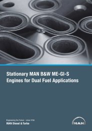
Bridge Wing<br />
tion. This will avoid any synchronizing of<br />
handles at the time of changing control<br />
position on the bridge.<br />
The electrical shaft standard solution<br />
can handle three panels on the bridge.<br />
However additional manoeuvring pan-<br />
els may be added, providing for typi-<br />
cally also an aft bridge. A maximum of<br />
16 panels can be controlled in one elec-<br />
trical shaft system.<br />
Telegraph system integrated in ma-<br />
noeuvre panels<br />
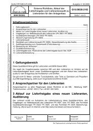
Main Control Station<br />
Bridge Center Bridge Wing<br />
Pitch Setpoint, Back-up Control<br />
Setpoint, Bridge<br />
Propeller Pitch<br />
Closed Loop<br />
Control Box<br />
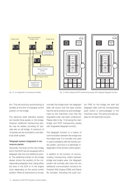
Fig. 12: A configuration of manoeuvre handles<br />
Optionally, the levers at the main bridge<br />
and in the ECR may be equipped with a<br />
telegraph dial and one additional point-<br />
er. The additional pointer on the bridge<br />
always shows the position of the cor-<br />
responding telegraph lever, being either<br />
the lever in the ECR or in the engine<br />
room depending on the actual control<br />
position. When an active lever is moved,<br />
Setpoint, ECR<br />
Remote Control<br />
System<br />
Main Cabinet<br />
12 <strong>Alphatronic</strong> <strong>2000</strong> <strong>PCS</strong> Propulsion Control System<br />
Electric Shaft<br />
Control Box<br />
Pitch Setpoint, RCS<br />
BACK UP<br />
CONTROL<br />
ON/OFF<br />
FINISH<br />
WITH<br />
ENGINE<br />
FULL<br />
HALF<br />
SLOW<br />
DEAD<br />
SLOW<br />
STOP<br />
DEAD<br />
SLOW<br />
SLOW<br />
HALF<br />
FULL<br />
STAND<br />
BY<br />
IN<br />
CONTROL<br />
EMERGENCY<br />
STOP<br />
TAKE<br />
CONTROL<br />
normally the bridge lever, the telegraph<br />
bells will sound until the reply pointer<br />
has the same position as acknowledge-<br />
ment by the machinery crew that the<br />
requested order has been understood.<br />
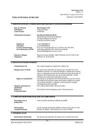
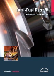
Please refer to fig. 13 showing the main<br />
bridge and ECR manoeuvring panels<br />
with integrated telegraph function.<br />
The telegraph function is a means of<br />
communication between the bridge and<br />
the engine area. It is normally only used<br />
in case of problems with the remote con-<br />
trol system, and thus it is electrically in-<br />
dependent of the remote control system.<br />
In addition to the function of commu-<br />
nicating manoeuvring orders between<br />
bridge and engine area, the telegraph<br />
system will normally also have the two<br />
additional communication functions for<br />
Finished With Engine (FWE) and Stand<br />
By included. Activating the push but-<br />
FINISH<br />
WITH<br />
ENGINE<br />
FULL<br />
HALF<br />
SLOW<br />
DEAD<br />
SLOW<br />
STOP<br />
DEAD<br />
SLOW<br />
SLOW<br />
HALF<br />
FULL<br />
STAND<br />
BY<br />
TELE-<br />
GRAPH<br />
ON/OFF<br />
EMERGENCY<br />
STOP<br />
ON<br />
SERVICE<br />
Fig. 13: Main bridge and ECR manoeuvring panels with integrated telegraph function<br />
ton FWE on the bridge will start the<br />
telegraph bells until the corresponding<br />
push button is acknowledged in the<br />
machinery area. The same principle ap-<br />
plies for the Stand By function.