Alphatronic 2000 PCS - MAN Diesel & Turbo
Alphatronic 2000 PCS - MAN Diesel & Turbo
Alphatronic 2000 PCS - MAN Diesel & Turbo

Create successful ePaper yourself
Turn your PDF publications into a flip-book with our unique Google optimized e-Paper software.
Primary control function<br />
The manoeuvre panels are fitted with<br />
manoeuvre levers for controlling the<br />
propeller speed and pitch. The lever on<br />
the bridge centre panel and the lever on<br />
the ECR panel have individual potenti-<br />
ometers connected to the main cabinet.<br />
Depending on the chosen mode of op-<br />
eration, these lever signals will be used<br />
for setting the engine speed and the<br />
propeller pitch accordingly.<br />
An electric speed setting signal is trans-<br />
mitted from the <strong>PCS</strong> main cabinet to<br />
the engine governor. If the engine has a<br />
governor with pneumatic speed setting,<br />
the electric speed order is converted<br />
into a pressure using an E/P–converter.<br />
The propeller pitch is controlled by two<br />
solenoid valves in the hydraulic system.<br />
The electronic servo unit controls the<br />
solenoid valves for ’ahead’ and ’astern’<br />
pitch changes by comparing actual<br />
pitch and set point. Actual propeller<br />
pitch is measured by two transmitters.<br />
One transmitter is used for indication<br />
of the actual position of the propeller.<br />
The other transmitter gives the feed-<br />
back signal to the electronic servo unit.<br />
In case of emergency<br />
If the propulsion control system is out<br />
of service, the propulsion plant may still<br />
be operated from the bridge using the<br />
back-up system. The back-up system<br />
is independent of the main control sys-<br />
tem, although it is operated from the<br />
same lever on the bridge.<br />
Selection of back-up will set the gov-<br />
ernor to a fixed speed (normally corre-<br />
sponding to the nominal shaft generator<br />
speed) and set the propeller pitch corre-<br />
sponding to the present thrust. Change<br />
8 <strong>Alphatronic</strong> <strong>2000</strong> <strong>PCS</strong> Propulsion Control System<br />
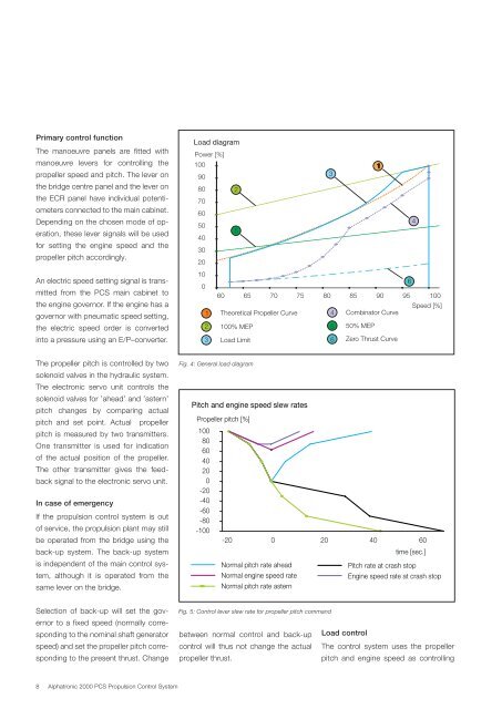
Load diagram<br />
Power [%]<br />
100<br />
90<br />
80<br />
70<br />
60<br />
50<br />
40<br />
30<br />
20<br />
10<br />
0<br />
1<br />
2<br />
5<br />
60 65 70 75 80 85 90 95 100<br />
Theoretical Propeller Curve<br />
3<br />
1<br />
Combinator Curve<br />
2 100% MEP<br />
5 50% MEP<br />
3<br />
Load Limit<br />
Fig. 4: General load diagram<br />
Pitch and engine speed slew rates<br />
Propeller pitch [%]<br />
100<br />
80<br />
60<br />
40<br />
20<br />
0<br />
-20<br />
-40<br />
-60<br />
-80<br />
-100<br />
4<br />
6<br />
Zero Thrust Curve<br />
-20 0 20 40 60<br />
6<br />
4<br />
time [sec.]<br />
Normal pitch rate ahead Pitch rate at crash stop<br />
Speed [%]<br />
Normal engine speed rate Engine speed rate at crash stop<br />
Normal pitch rate astern<br />
Fig. 5: Control lever slew rate for propeller pitch command<br />
between normal control and back-up<br />
control will thus not change the actual<br />
propeller thrust.<br />
Load control<br />
The control system uses the propeller<br />
pitch and engine speed as controlling