Alphatronic 2000 PCS - MAN Diesel & Turbo
Alphatronic 2000 PCS - MAN Diesel & Turbo
Alphatronic 2000 PCS - MAN Diesel & Turbo

You also want an ePaper? Increase the reach of your titles
YUMPU automatically turns print PDFs into web optimized ePapers that Google loves.
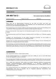
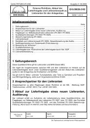
Bridge wing manoeuvre panels<br />
Typically, two bridge wing panels are<br />
supplied. Wing panels are available in<br />
indoor and outdoor versions. Indoor<br />
wing panels may optionally be equipped<br />
with a Propulsion Control Panel if de-<br />
sired. Please refer to figures 10 and 11.<br />
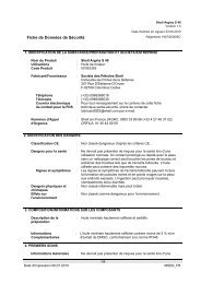
Control levers in the manoeuvring<br />
handle panels<br />
Fig. 12 shows a typical control lever<br />
configuration. The control lever in the<br />
bridge main manoeuvre panel is con-<br />
nected to the main cabinet of the re-<br />
mote control system.<br />
As standard the engine control room<br />
(ECR) is equipped with a similar control<br />
lever. Optionally the system can be de-<br />
livered without equipment in the engine<br />
control room.<br />
The control lever in the bridge main ma-<br />
noeuvre panel and the control lever in<br />
the ECR are independent of each other.<br />
Electrical shaft system<br />
Ships with bridge wing control are<br />
equipped with an electrical shaft sys-<br />
tem interconnecting the bridge main<br />
and bridge wing control levers.<br />
The electric shaft system is a so-called<br />
synchronizing system, in which the<br />
non-active control levers are following<br />
the active control lever. I.e. when the<br />
bridge main manoeuvre panel is select-<br />
ed as “IN CONTROL”, the two bridge<br />
wing levers will automatically follow the<br />
bridge main control lever.<br />
This system design secures that the<br />
handle chosen to be “IN CONTROL”<br />
will act as a master and the other han-<br />
dles on the bridge will follow its posi-<br />
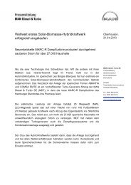
Fig. 9: Bridge manoeuvre panel – main bridge<br />
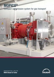
Fig. 10: Bridge manoeuvre panel – bridge wing indoor<br />
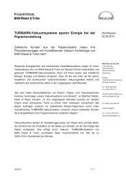
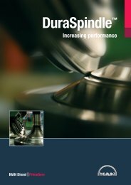
Fig. 11: Bridge manoeuvre panel – bridge wing outdoor<br />
<strong>Alphatronic</strong> <strong>2000</strong> <strong>PCS</strong> Propulsion Control System<br />
11