DS 2-8 Earthquake Protection for Water-Based Fire ... - FM Global
DS 2-8 Earthquake Protection for Water-Based Fire ... - FM Global
DS 2-8 Earthquake Protection for Water-Based Fire ... - FM Global

You also want an ePaper? Increase the reach of your titles
YUMPU automatically turns print PDFs into web optimized ePapers that Google loves.
<strong>FM</strong> <strong>Global</strong><br />
Property Loss Prevention Data Sheets 2-8<br />
May 2010<br />
Page1of65<br />
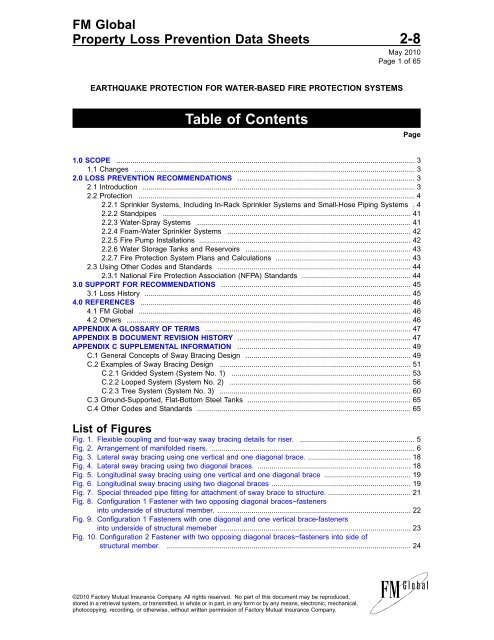
EARTHQUAKE PROTECTION FOR WATER-BASED FIRE PROTECTION SYSTEMS<br />
Table of Contents<br />
1.0 SCOPE .................................................................................................................................................... 3<br />
1.1 Changes ........................................................................................................................................... 3<br />
2.0 LOSS PREVENTION RECOMMENDATIONS ........................................................................................ 3<br />
2.1 Introduction ....................................................................................................................................... 3<br />
2.2 <strong>Protection</strong> ......................................................................................................................................... 4<br />
2.2.1 Sprinkler Systems, Including In-Rack Sprinkler Systems and Small-Hose Piping Systems . 4<br />
2.2.2 Standpipes ........................................................................................................................... 41<br />
2.2.3 <strong>Water</strong>-Spray Systems .......................................................................................................... 41<br />
2.2.4 Foam-<strong>Water</strong> Sprinkler Systems ........................................................................................... 42<br />
2.2.5 <strong>Fire</strong> Pump Installations ......................................................................................................... 42<br />
2.2.6 <strong>Water</strong> Storage Tanks and Reservoirs .................................................................................. 43<br />
2.2.7 <strong>Fire</strong> <strong>Protection</strong> System Plans and Calculations ................................................................... 43<br />
2.3 Using Other Codes and Standards ................................................................................................ 44<br />
2.3.1 National <strong>Fire</strong> <strong>Protection</strong> Association (NFPA) Standards ...................................................... 44<br />
3.0 SUPPORT FOR RECOMMENDATIONS .............................................................................................. 45<br />
3.1 Loss History .................................................................................................................................... 45<br />
4.0 REFERENCES ...................................................................................................................................... 46<br />
4.1 <strong>FM</strong> <strong>Global</strong> ....................................................................................................................................... 46<br />
4.2 Others ............................................................................................................................................. 46<br />
APPENDIX A GLOSSARY OF TERMS ...................................................................................................... 47<br />
APPENDIX B DOCUMENT REVISION HISTORY ...................................................................................... 47<br />
APPENDIX C SUPPLEMENTAL INFORMATION ...................................................................................... 49<br />
C.1 General Concepts of Sway Bracing Design .................................................................................. 49<br />
C.2 Examples of Sway Bracing Design ............................................................................................... 51<br />
C.2.1 Gridded System (System No. 1) ......................................................................................... 53<br />
C.2.2 Looped System (System No. 2) .......................................................................................... 56<br />
C.2.3 Tree System (System No. 3) ............................................................................................... 60<br />
C.3 Ground-Supported, Flat-Bottom Steel Tanks ................................................................................. 65<br />
C.4 Other Codes and Standards .......................................................................................................... 65<br />
List of Figures<br />
Fig. 1. Flexible coupling and four-way sway bracing details <strong>for</strong> riser. ......................................................... 5<br />
Fig. 2. Arrangement of manifolded risers. ..................................................................................................... 6<br />
Fig. 3. Lateral sway bracing using one vertical and one diagonal brace. ................................................... 18<br />
Fig. 4. Lateral sway bracing using two diagonal braces. ............................................................................ 18<br />
Fig. 5. Longitudinal sway bracing using one vertical and one diagonal brace ........................................... 19<br />
Fig. 6. Longitudinal sway bracing using two diagonal braces ..................................................................... 19<br />
Fig. 7. Special threaded pipe fitting <strong>for</strong> attachment of sway brace to structure. ......................................... 21<br />
Fig. 8. Configuration 1 Fastener with two opposing diagonal braces−fasteners<br />
into underside of structural member. ................................................................................................ 22<br />
Fig. 9. Configuration 1 Fasteners with one diagonal and one vertical brace-fasteners<br />
into underside of structural memeber ............................................................................................... 23<br />
Fig. 10. Configuration 2 Fastener with two opposing diagonal braces−fasteners into side of<br />
structural member. ......................................................................................................................... 24<br />
©2010 Factory Mutual Insurance Company. All rights reserved. No part of this document may be reproduced,<br />
stored in a retrieval system, or transmitted, in whole or in part, in any <strong>for</strong>m or by any means, electronic, mechanical,<br />
photocopying, recording, or otherwise, without written permission of Factory Mutual Insurance Company.<br />
Page
2-8 <strong>Earthquake</strong> <strong>Protection</strong><br />
Page 2 <strong>FM</strong> <strong>Global</strong> Property Loss Prevention Data Sheets<br />
Fig. 11. Configuration 2 Fasteners with one diagonal and one vertical brace-fasterners into side of<br />
structural member ........................................................................................................................... 24<br />
Fig. 12. Configuration 3 Fastener with two opposing diagonal braces−fasteners into face of<br />
structural member. .......................................................................................................................... 25<br />
Fig. 13. Configuration 3 Fasteners with one diagonal and one vertical brace−fasteners into face of<br />
structural member. .......................................................................................................................... 25<br />
Fig. 14. Detail of connection of sway brace to side of wood beam with through bolt. .............................. 26<br />
Fig. 15 Dimensional locations <strong>for</strong> lag screws and through bolts in wood.. ................................................. 27<br />
Fig. 16. Pilot hole sizing <strong>for</strong> lag screws−use with Table 8. ......................................................................... 27<br />
Fig. 17. Examples of bracing attachments to piping ................................................................................... 34<br />
Fig. 18. Arrangement of flexible couplings <strong>for</strong> risers passing through floors of multistory buildings .......... 35<br />
Fig. 19. Arrangement of combination risers <strong>for</strong> ceiling sprinklers and in-rack sprinklers/hose stations ..... 36<br />
Fig. 20. Arrangements <strong>for</strong> piping feeding in-rack sprinklers. ....................................................................... 37<br />
Fig. 21. Arrangements <strong>for</strong> pipe drops supplying sprinklers below ceilings, mezzanines, walkways, ets. .. 38<br />
Fig. 22. Seismic separation assembly <strong>for</strong> fire protection system piping that crosses a seismic<br />
building expansion joint above ground level .................................................................................. 39<br />
Fig. 23. Example of building with three sprinkler rises and three types of sprinkler system configurations .52<br />
Fig. 24. Layout and zones of influence <strong>for</strong> lateral and four-way riser sway bracing <strong>for</strong> System #1. .......... 52<br />
Fig. 25. Layout and zones of influence <strong>for</strong> longitudinal and four-way riser sway bracing <strong>for</strong> System #1. .53<br />
Fig. 26. Layout and zones of influence <strong>for</strong> lateral and four-way riser sway bracing <strong>for</strong> System #2. .......... 57<br />
Fig. 27. Layout and zones of influence <strong>for</strong> longitudinal and four-way riser sway bracing <strong>for</strong> System #2. .57<br />
Fig. 28. Layout and zones of influence <strong>for</strong> lateral and four-way riser sway bracing <strong>for</strong> System #3. .......... 60<br />
Fig. 29. Layout and zones of influence <strong>for</strong> longitudinal and four-way riser sway bracing <strong>for</strong> System #3. .61<br />
List of Tables<br />
Table 1. Weight of <strong>Water</strong>-Filled Pipe .............................................................................................................. 9<br />
Table 2. Maximum Horizontal Loads (lb) <strong>for</strong> Steel Sway Brace Members in Compression (l/r = 100) ...... 12<br />
Table 3. Maximum Horizontal Loads (N) <strong>for</strong> Steel Sway Brace Members in Compression (Metric)<br />
(l/r = 100) ........................................................................................................................................ 13<br />
Table 4. Maximum Horizontal Loads (lb) <strong>for</strong> Steel Sway Brace Members in Compression (l/r = 200) ...... 14<br />
Table 5. Maximum Horizontal Loads (N) <strong>for</strong> Steel Sway Brace Members in Compression (Metric)<br />
(l/r = 200) ........................................................................................................................................ 15<br />
Table 6. Maximum Horizontal Loads (lb) <strong>for</strong> Steel Sway Brace Members in Compression (l/r = 300) ...... 16<br />
Table 7. Maximum Horizontal Loads (N) <strong>for</strong> Steel Sway Brace Members in Compression (Metric)<br />
(l/r = 300) ........................................................................................................................................ 17<br />
Table 8. Hole Dimensions <strong>for</strong> Lag Screws ................................................................................................... 29<br />
Table 9. Maximum Horizontal Load <strong>for</strong> Through Bolts in Wood, lb ............................................................. 30<br />
Table 10. Maximum Horizontal Load <strong>for</strong> Through Bolts in Wood, N ........................................................... 31<br />
Table 11. Maximum Horizontal Load <strong>for</strong> Lag Screws in Wood, lb .............................................................. 31<br />
Table 12. Maximum Horizontal Load <strong>for</strong> Lag Screws in Wood, N .............................................................. 32<br />
Table 13. Maximum Horizontal Load <strong>for</strong> Post-Installed Concrete Expansion or Wedge Anchors in<br />
2500 psi Normal Weight Concrete 1 ,lb ........................................................................................ 32<br />
Table 14. Maximum Horizontal Load <strong>for</strong> Post-Installed Concrete Expansion or Wedge Anchors in<br />
17.2 MPa Normal Weight Concrete 1 ,N ...................................................................................... 33<br />
Table 15. Maximum Horizontal Load <strong>for</strong> Through Bolts in Steel (bolt perpendicular to mounting<br />
surface), lb ................................................................................................................................... 33<br />
Table 16. Maximum Horizontal Load <strong>for</strong> Through Bolts in Steel (bolt perpendicular to mounting surface), N .33<br />
Table 17. Horizontal Seismic Design Loads <strong>for</strong> System No. 1. ............................................................. 54<br />
Table 18. Horizontal Seismic Design Load Calculations <strong>for</strong> System No. 2. ........................................... 58<br />
Table 19. Horizontal Seismic Design Loads <strong>for</strong> System No. 3. ............................................................. 62<br />
©2010 Factory Mutual Insurance Company. All rights reserved.
<strong>Earthquake</strong> <strong>Protection</strong> 2-8<br />
<strong>FM</strong> <strong>Global</strong> Property Loss Prevention Data Sheets Page 3<br />
1.0 SCOPE<br />
This data sheet provides recommendations <strong>for</strong> earthquake protection of fixed water-based fire protection<br />
systems. Apply these recommendations to locations in <strong>FM</strong> <strong>Global</strong> 50-year through 500-year earthquake<br />
zones, as described in Data Sheet 1-2, <strong>Earthquake</strong>s.<br />
Loads and capacities in this data sheet are based on the Allowable Stress Design analysis method.<br />
1.1 Changes<br />
May 2010. This data sheet has been revised in its entirety to provide a consistent <strong>for</strong>mat. Editorial corrections<br />
(such as revising metric sizes) were made throughout the document. Several technical revisions were made<br />
as well, the most significant of which include the following:<br />
• Clarified that design basis is Allowable Stress Design (Section 1.0).<br />
• Changed the design coefficient “G” <strong>for</strong> <strong>FM</strong> <strong>Global</strong> 50-year, 250-year, and 500-year zones (Section<br />
2.2.1.2.2).<br />
• Modified in<strong>for</strong>mation on attachments to concrete in Section 2.2.1.3.6.<br />
• Added flexibility guidelines <strong>for</strong> unanchored suction tanks (Section 2.2.6.1.4).<br />
• Added Section 2.3 regarding the use of other codes and standards.<br />
• Added references to Section 4.0.<br />
• Added glossary terms to Appendix A.<br />
• Relocated commentary to Appendix C.<br />
• Updated Figs. 2-6, 8, 10, 12, 14-16, and 18-29.<br />
• Revised brace capacities (Tables 2-7), wood through-bolt and lag-screw capacities (Tables 9-12), and<br />
concrete anchor capacities (Tables 13 and 14).<br />
• Made minor revisions to Tables 1, 8, and 15-19.<br />
2.0 LOSS PREVENTION RECOMMENDATIONS<br />
2.1 Introduction<br />
<strong>Earthquake</strong>-related strains are imparted to a fire protection system through the building or the ground to<br />
which it is attached, or through inertial movement within the system itself. Uncontrolled differential movement<br />
can cause damage when fire protection systems are not provided in a systematic manner with the necessary<br />
features that incorporate sway bracing, flexibility, clearance, and anchorage where needed. Because an<br />
uncontrolled fire after an earthquake can result in a devastating loss, the primary concern related to<br />
deficiencies in earthquake protection is that the fire protection systems will be impaired as a result of strong<br />
ground shaking. In terms of frequency, however, the most common type of damage, based on past<br />
experience, is due to water leakage from broken overhead sprinkler piping or sprinklers, primarily due to lack<br />
of sway bracing where needed.<br />
Common sources of water damage are broken or separated overhead sprinkler piping, broken sprinklers<br />
due to impact with nearby structural members or other equipment, broken sprinklers or pipe drops due to<br />
excessive differential movement between unbraced suspended ceilings and the pipe drops, and broken<br />
in-rack sprinkler system piping or sprinklers due to excessive rack movement. In addition to damage from<br />
water leakage, fire protection systems are often impaired due to direct damage to the systems, or due to<br />
damage to public water supplies or utilities needed <strong>for</strong> fire protection. Significant impairments to fire protection<br />
systems may expose a facility to a severe fire loss following an earthquake.<br />
In evaluating the many incidents of damage, two conclusions are very apparent:<br />
1. Only by providing, in a systematic manner, the necessary features (which incorporate sway<br />
bracing, flexibility, clearance, and anchorage where needed) can a fire protection system be<br />
adequately protected from earthquake damage.<br />
©2010 Factory Mutual Insurance Company. All rights reserved.
2-8 <strong>Earthquake</strong> <strong>Protection</strong><br />
Page 4 <strong>FM</strong> <strong>Global</strong> Property Loss Prevention Data Sheets<br />
2. The omission of even a few of the critical components necessary <strong>for</strong> adequate earthquake<br />
protection may result in impairment of the system or substantial water damage. The necessary<br />
shutdown of the system to stop further water damage also creates a long-term fire protection<br />
system impairment.<br />
The recommendations in this data sheet are intended to: (1) greatly improve the likelihood that the fire<br />
protection system(s) will remain in working condition after the earthquake, and (2) minimize potential water<br />
damage from fire protection system leakage. For each type of fire protection system described in the<br />
following sections, completion of all recommendations will maximize the probability of the system per<strong>for</strong>ming<br />
as intended during an earthquake.<br />
In general, recommendations are related to the following seven goals:<br />
1. Bracing piping and equipment to minimize uncontrolled differential movement between these items<br />
and the structure(s) to which they are attached.<br />
2. Providing flexibility on piping systems and on other equipment where differential movement between<br />
portions of those piping systems or equipment is expected. Except where large differential movement<br />
occurs over a short distance, flexible couplings provide sufficient flexibility between portions of sprinkler<br />
piping systems where needed.<br />
3. Providing clearance between piping or equipment and structural members, walls, floors, or other objects<br />
so that potential damage from impact is minimized.<br />
4. Providing anchorage to minimize potential sliding and/or overturning.<br />
5. Using appropriate types of pipe hangers and sway bracing, properly located and attached to the structure<br />
to minimize the potential <strong>for</strong> pullout.<br />
6. Using appropriate types of piping and pipe-joining methods to minimize potential pipe breaks.<br />
7. Providing fire protection system plans and calculations with proper verification of design, and proper<br />
verification that the completed installation is in accordance with the design as well as good installation<br />
practices.<br />
NOTE: See Section 2.3 <strong>for</strong> guidance on using other codes and standards to provide earthquake<br />
protection of fire protection systems similar to that recommended in this data sheet.<br />
2.2 <strong>Protection</strong><br />
2.2.1 Sprinkler Systems, Including In-Rack Sprinkler Systems and Small-Hose Piping Systems<br />
2.2.1.1 Sway Bracing Locations<br />
2.2.1.1.1 Lay out sway bracing locations (a) per Sections 2.2.1.1.2 through 2.2.1.1.5, unless closer spacing<br />
is needed based on brace or attachment capacity limits, and (b) so that sway bracing locations will coincide<br />
with the structural members to which the sway braces will be attached.<br />
2.2.1.1.2 Brace all sprinkler system risers whether they are single or manifolded type, and regardless of size,<br />
in accordance with the following guidelines.<br />
A. Provide a four-way sway brace within 2 ft (0.6 m) of the top of the riser as shown in Fig. 1. For risers<br />
located on the outside of the building, either Detail A or B of Fig. 1 may be used, with the brace attached<br />
to a structural element. When possible, avoid the use of manifolded sway bracing at the top of multiple<br />
adjacent risers. If used, limit the manifolded arrangement to two risers, and design bracing to carry the<br />
total loads <strong>for</strong> both risers.<br />
B. Provide intermediate four-way sway bracing at an interval not to exceed 40 ft (12.2 m). Where flexible<br />
couplings are used, arrange this intermediate four-way sway bracing so a brace is provided within 2 ft<br />
(0.6 m) of every other flexible coupling (adding four-way braces if necessary). In multistory buildings, lay<br />
out bracing so a four-way brace is provided at each floor having a supply main; a four-way brace is<br />
considered to exist when the riser passes through a structural floor, and clearances do not exceed the<br />
minimums per Section 2.2.1.5.1.<br />
©2010 Factory Mutual Insurance Company. All rights reserved.
<strong>Earthquake</strong> <strong>Protection</strong> 2-8<br />
<strong>FM</strong> <strong>Global</strong> Property Loss Prevention Data Sheets Page 5<br />
Fig. 1. Flexible coupling and four-way sway bracing details <strong>for</strong> riser. NOTE: <strong>for</strong> risers located outside of<br />
buildings, Detail A or B may be used with the bracing attached to a structural element.<br />
C. Provide a two-way lateral sway brace within 2 ft (0.6 m) of the end of any horizontal manifold piping<br />
longer than 6 ft (1.8 m), or when there is one or more flexible coupling(s) on either the horizontal manifold<br />
piping or on the riser stub between the floor and the connection to the horizontal manifold piping. See<br />
Fig. 2.<br />
2.2.1.1.3 Brace vertical crossmain or feedmain piping, regardless of size, in accordance with the following<br />
guidelines.<br />
A. Provide four-way sway bracing at both the top and bottom of the vertical pipe run of 6 ft (1.8 m) or<br />
more. Locate each brace on the largest diameter pipe within 2 ft (0.6 m) of the respective piping turn.<br />
Provide intermediate four-way sway bracing similar to risers as recommended in Section 2.2.1.1.2(B).<br />
B. For vertical pipe runs of less than 6 ft (1.8 m) without bracing provided, flexible couplings should not<br />
be present within the vertical pipe run (including the piping turns). If flexible couplings are used or needed<br />
to satisfy flexibility recommendations (e.g., <strong>for</strong> pipe drops) at one or both turns <strong>for</strong> vertical pipe runs of<br />
less than 6 ft (1.8 m), then provide four-way bracing on the largest diameter pipe within 2 ft (0.6 m) of each<br />
turn equipped with flexible coupling(s).<br />
2.2.1.1.4 Brace horizontal crossmain or feedmain piping, regardless of size, in accordance with the following<br />
guidelines.<br />
A. Horizontal changes of direction: Provide crossmain or feedmain piping that has pipe runs of 6 ft (1.8<br />
m) or more adjacent to the change in direction with both lateral and longitudinal sway bracing within 2 ft<br />
(0.6 m) of the change of direction. If the diameter of the main reduces at the change of direction, locate<br />
©2010 Factory Mutual Insurance Company. All rights reserved.
2-8 <strong>Earthquake</strong> <strong>Protection</strong><br />
Page 6 <strong>FM</strong> <strong>Global</strong> Property Loss Prevention Data Sheets<br />
Fig. 2. Arrangement of manifolded risers.<br />
braces on the larger diameter pipe. Provide straight pipe runs after the change in direction with sway<br />
bracing per Sections 2.2.1.1.4(B) through 2.2.1.1.4(D). Note that when the pipe connection at the change<br />
in direction is made using a flexible coupling, then additional sway bracing per Section 2.2.1.1.4(C) will<br />
be necessary, regardless of the length of the pipe run adjacent to the change in direction.<br />
B. Ends of feedmains and crossmains: Provide lateral bracing within 6 ft (1.8 m) of the end, and provide<br />
longitudinal bracing within 40 ft (12.2 m) of the end. When structural member locations <strong>for</strong> lateral sway<br />
bracing attachment are such that this 6 ft (1.8 m) distance cannot be met, extend the crossmain or<br />
feedmain to allow proper location of the lateral sway bracing. Consider seismic separation assemblies in<br />
feedmains and crossmains per Section 2.2.1.4.8 as the end of the piping on both sides of the assembly.<br />
C. Unnecessary flexible couplings: When more flexible couplings than recommended in Section 2.2.1.4<br />
are installed on feedmains or crossmains, install additional lateral sway bracing as follows:<br />
1. Within 2 ft (0.6 m) of every other flexible coupling on straight pipe runs, and<br />
2. Within 2 ft (0.6 m) of every flexible coupling installed at changes in horizontal pipe direction.<br />
D. Straight pipe runs: After giving credit to any sway bracing installed per Sections 2.2.1.1.1 to 2.2.1.1.4(C),<br />
provide sway bracing on feedmains and crossmains at a maximum spacing of 40 ft (12.2 m) <strong>for</strong> lateral<br />
sway bracing and 80 ft (24.4 m) <strong>for</strong> longitudinal sway bracing using the following guidelines.<br />
1. A four-way brace on a vertical pipe (e.g., at the top of the riser) may be counted as the initial lateral<br />
and longitudinal brace <strong>for</strong> the attached horizontal pipe (i.e., feedmain or crossmain) of the same or<br />
smaller diameter when the brace is located within 2 ft (0.6 m) of the horizontal pipe. Recognize that<br />
the design load <strong>for</strong> this four-way brace should include the tributary load from both the vertical and the<br />
horizontal pipe.<br />
©2010 Factory Mutual Insurance Company. All rights reserved.
<strong>Earthquake</strong> <strong>Protection</strong> 2-8<br />
<strong>FM</strong> <strong>Global</strong> Property Loss Prevention Data Sheets Page 7<br />
2. A lateral brace within 2 ft (0.6 m) of the end of a feedmain or crossmain piping connection to another<br />
main that is perpendicular and of the same or lesser diameter may be used to also act as a longitudinal<br />
brace <strong>for</strong> the perpendicular main. Recognize that the sway brace design load includes the tributary<br />
lateral and longitudinal loads <strong>for</strong> the braced mains.<br />
3. A longitudinal brace within 2 ft (0.6 m) of the end of a feedmain or crossmain piping connection to<br />
another main that is perpendicular and of the same or lesser diameter may be used to also act as a<br />
lateral brace <strong>for</strong> the perpendicular main. Recognize that the sway brace design load includes the<br />
tributary lateral and longitudinal loads <strong>for</strong> the braced mains.<br />
4. A properly sized and attached U-bolt that fastens the pipe directly to, and holds the pipe tightly<br />
against, a structural supporting member may be used as a lateral brace.<br />
5. Do not use U-hangers, including wraparound types, as lateral sway bracing <strong>for</strong> feedmains and<br />
crossmains.<br />
6. For feedmains and crossmains, do not omit lateral sway bracing even if pipes are individually<br />
supported by short hanger rods.<br />
7. Do not consider any sway bracing on branch lines as providing lateral or longitudinal sway bracing<br />
of the crossmain.<br />
2.2.1.1.5 Sprinkler system branch lines that are less than 2- 1 ⁄ 2 in. (65 mm) in diameter do not require bracing.<br />
Brace larger sprinkler system branch lines as described below.<br />
A. Provide lateral sway bracing on all branch lines and portions of branch lines, including portions adjacent<br />
to changes in direction, that are 2- 1 ⁄ 2 in (65 mm) and larger and greater than 20 ft (6.1 m) in length in<br />
accordance with the following guidelines.<br />
1. For branch lines less than 4 in. (100 mm) in diameter, lateral sway bracing is not needed on pipes<br />
individually supported by rods that meet the following criteria:<br />
• All rods have a length less than 6 in. (150 mm) from the supporting member attachment to the<br />
top of the branch line, and<br />
•there is no more than 1 ⁄ 2 in. (13 mm) of space between the top of the branch line piping and the<br />
bottom of the support rod.<br />
2. A four-way brace on a vertical pipe (e.g., at the bottom of a drop) may be counted as the initial lateral<br />
brace <strong>for</strong> the attached horizontal branch line of the same or smaller diameter when the brace is located<br />
within 2 ft (0.6 m) of the horizontal pipe. Recognize that the design load <strong>for</strong> this four-way brace should<br />
include the tributary load from both the vertical and the horizontal pipe.<br />
3. A longitudinal brace within 2 ft (0.6 m) of the end of a branch line connection to another branch line<br />
that is perpendicular and of the same or lesser diameter may be used to also act as a lateral brace<br />
<strong>for</strong> the perpendicular branch line. Recognize that the sway brace design load includes the tributary<br />
lateral and longitudinal loads <strong>for</strong> the braced branch lines.<br />
4. A properly sized and attached U-bolt that fastens the pipe directly to, and holds the pipe tightly<br />
against, a structural supporting member may be used as a lateral brace.<br />
5. Wraparound U-hangers may be used as lateral sway bracing <strong>for</strong> branch lines if they meet the criteria<br />
per Section 2.2.1.3.4.<br />
6. When more flexible couplings than recommended in Section 2.2.1.4 are installed, provide additional<br />
lateral sway bracing:<br />
a. within 2 ft (0.6 m) of every other flexible coupling on straight pipe runs, and<br />
b. within 2 ft (0.6 m) of every flexible coupling installed at changes in horizontal pipe direction.<br />
7. Locate the first lateral sway bracing no closer than 10 ft (3.1 m) nor greater than 40 ft (12.2 m),<br />
including all vertical and horizontal branch line section lengths, from the branch line connection to the<br />
crossmain.<br />
8. For dead-end branch lines locate the last lateral brace not more than 6 ft (1.8 m) from the end.<br />
Consider seismic separation assemblies per Section 2.2.1.4.8 as the end of the piping on both sides<br />
of the assembly.<br />
©2010 Factory Mutual Insurance Company. All rights reserved.
2-8 <strong>Earthquake</strong> <strong>Protection</strong><br />
Page 8 <strong>FM</strong> <strong>Global</strong> Property Loss Prevention Data Sheets<br />
9. Locate a lateral brace not more than 6 ft (1.8 m) from horizontal changes in direction.<br />
10. After giving credit to any lateral sway bracing installed or allowed to be omitted per items 1 to 9<br />
above, provide lateral sway bracing on straight runs of pipe spaced at a maximum of 40 ft (12.2 m).<br />
B. Provide longitudinal sway bracing on all branch lines and portions of branch lines (including portions<br />
adjacent to changes in direction) that are 2- 1 ⁄ 2 in (65 mm) and larger and greater than 40 ft (12.2 m) in<br />
length in accordance with the following guidelines.<br />
1. A four-way brace on a vertical pipe (e.g., at the bottom of a drop) may be counted as the initial<br />
longitudinal brace <strong>for</strong> the attached horizontal branch line of the same or smaller diameter when the<br />
brace is located within 2 ft (0.6 m) of the horizontal pipe. Recognize that the design load <strong>for</strong> this four-way<br />
brace should include the tributary load from both the vertical and the horizontal pipe.<br />
2. A lateral brace within 2 ft (0.6 m) of the end of a branch line connection to another branch line that<br />
is perpendicular and of the same or lesser diameter may be used to also act as a longitudinal brace<br />
<strong>for</strong> the perpendicular branch line. Recognize that the sway brace design load includes the tributary<br />
lateral and longitudinal loads <strong>for</strong> the braced branch lines.<br />
3. Locate the first longitudinal sway bracing location closest to the crossmain between 20 ft and 80 ft<br />
(6.1 m and 24.4 m), including all vertical and horizontal branch line section lengths, from the branch<br />
line connection to the crossmain.<br />
4. For dead-end branch lines, locate the last longitudinal brace not more than 40 ft (12.2 m) from the<br />
end. Consider seismic separation assemblies per Section 2.2.1.4.8 as the end of the piping on both<br />
sides of the assembly.<br />
5. Locate a longitudinal brace not more than 40 ft (12.2 m) from horizontal changes in direction.<br />
6. After giving credit to any longitudinal sway bracing installed per items 1 through 5 above, provide<br />
longitudinal sway bracing on straight runs of pipe spaced at a maximum of 80 ft (24.4 m).<br />
2.2.1.2 Horizontal Seismic Loads <strong>for</strong> Sway Bracing Design<br />
2.2.1.2.1 Determine the horizontal design load (H) <strong>for</strong> each sway bracing location by multiplying the weight<br />
of the water-filled piping located within the zone of influence (W p) <strong>for</strong> that sway bracing location times the<br />
horizontal acceleration (“G” factor) expected from an earthquake. For simplicity of calculations, the same W p<br />
may be used <strong>for</strong> the design of several braces as long as it is based on the weight of water-filled pipe in the<br />
controlling zone of influence. Table 1 shows weights <strong>for</strong> water-filled pipe to be used with the appropriate<br />
“G” factor to calculate design loads.<br />
2.2.1.2.2 Use a minimum “G” factor of 0.75 in <strong>FM</strong> <strong>Global</strong> 50-year earthquake zones, 0.5 in <strong>FM</strong> <strong>Global</strong> 100-year<br />
earthquake zones, and 0.4 in <strong>FM</strong> <strong>Global</strong> 250- and 500-year earthquake zones. These “G” factors are based<br />
on the Allowable Stress Design analysis method. Use a higher “G” factor if required by local authorities per<br />
the building code <strong>for</strong> the location involved.<br />
©2010 Factory Mutual Insurance Company. All rights reserved.
<strong>Earthquake</strong> <strong>Protection</strong> 2-8<br />
<strong>FM</strong> <strong>Global</strong> Property Loss Prevention Data Sheets Page 9<br />
Pipe Nominal Diameter<br />
in. (mm)<br />
Table 1. Weight of <strong>Water</strong>-Filled Pipe<br />
Weight,<br />
lb/ft (N/m)<br />
Schedule 40<br />
1 (25) 2.1 (31)<br />
1-1 ⁄ 4 (32) 2.9 (43)<br />
1-1 ⁄ 2 (40) 3.6 (53)<br />
2 (50) 5.1 (75)<br />
2-1 ⁄ 2 (65) 7.9 (116)<br />
3 (80) 10.8 (159)<br />
3-1 ⁄ 2 (90) 13.5 (198)<br />
4 (100) 16.4 (241)<br />
5 (125) 23.5 (345)<br />
6 (150) 31.7 (465)<br />
8* (200) 47.7 (700)<br />
Schedule 10 and Lightwall<br />
1 (25) 1.8 (26)<br />
1-1 ⁄ 4 (32) 2.5 (37)<br />
1-1 ⁄ 2 (40) 3.0 (44)<br />
2 (50) 4.2 (62)<br />
2-1 ⁄ 2 (65) 5.9 (87)<br />
3 (80) 7.9 (116)<br />
3-1 ⁄ 2 (90) 9.8 (144)<br />
4 (100) 11.8 (173)<br />
5 (125) 17.3 (254)<br />
6 (150) 23.0 (338)<br />
8 (200) 40.1 (589)<br />
* Schedule 30<br />
2.2.1.2.3 Determine the weight (Wp) to be used <strong>for</strong> each sway brace design (or each controlling sway brace<br />
design) by including the water-filled weight of all piping within the zone of influence, defined below.<br />
A. Four-way sway bracing at risers, vertical feedmains and crossmains, and drops:<br />
1. Where the four-way sway brace restrains only the vertical pipe (e.g., an intermediate riser brace<br />
where there is no attached feedmain or crossmain) the zone of influence includes the length of the<br />
vertical pipe above and below the sway brace that is tributary to that sway brace. Use the resulting<br />
weight of pipe to determine the load to be applied in each orthogonal horizontal direction.<br />
2. Where the four-way sway brace <strong>for</strong> the vertical pipe also serves as a lateral and longitudinal sway<br />
brace <strong>for</strong> an attached horizontal pipe (e.g., feedmain or crossmain), the four-way sway brace zone<br />
of influence is determined as follows.<br />
a. In the lateral direction of the horizontal pipe, add the tributary length of vertical pipe above and<br />
below the sway brace, plus the tributary lengths of feedmain, crossmain, and branch line piping,<br />
as described in Section 2.2.1.2.3(B), located between the four-way sway brace and the first lateral<br />
sway brace on the horizontal pipe.<br />
b. In the longitudinal direction of the horizontal pipe, add the tributary length of vertical pipe above<br />
and below the sway brace, plus the tributary lengths of feedmain, crossmain, and branch line<br />
piping, as described in Section 2.2.1.2.3(C), located between the four-way sway brace and the<br />
first longitudinal sway brace on the horizontal pipe.<br />
3. The weight of the water-filled pipe <strong>for</strong> manifolded bracing design includes the total load <strong>for</strong> the two<br />
risers being braced.<br />
B. Lateral two-way sway bracing:<br />
1. For feedmains, the zone of influence includes the length of the feedmain to the left and right of the<br />
sway brace that is tributary to that brace.<br />
©2010 Factory Mutual Insurance Company. All rights reserved.
2-8 <strong>Earthquake</strong> <strong>Protection</strong><br />
Page 10 <strong>FM</strong> <strong>Global</strong> Property Loss Prevention Data Sheets<br />
2. For crossmains, the zone of influence includes the tributary length of crossmain being braced plus<br />
the length of all branch lines attached to that section of crossmain that are not distributed to branch<br />
line longitudinal sway bracing.<br />
3. For branch lines that require sway bracing, the zone of influence typically includes the length of<br />
the branch line to the left and right of the sway brace that is tributary to that sway brace. The tributary<br />
length of pipe between the first lateral sway bracing location and the crossmain connection may either<br />
be based on an equal distribution to the crossmain longitudinal bracing and the first lateral sway<br />
bracing location (see Section 2.2.1.2.3[C][2]), or may be totally distributed to the first lateral sway<br />
bracing location.<br />
C. Longitudinal two-way sway bracing:<br />
1. For feedmains, the zone of influence includes the length of the feedmain to the left and right of the<br />
sway brace that is tributary to that brace.<br />
2. For crossmains, the zone of influence includes the tributary length of crossmain being braced; do<br />
not include loads from branch lines, except when a portion of branch line lateral sway bracing is being<br />
included as described in Section 2.2.1.2.3(B)(3).<br />
3. For branch lines that require sway bracing, the zone of influence typically includes the length of<br />
the branch line to the left and right of the sway brace that is tributary to that sway brace. The tributary<br />
length <strong>for</strong> the piping between the crossmain and the first sway bracing location should be based on<br />
an equal distribution between that bracing location and the crossmain lateral sway bracing as described<br />
in Section 2.2.1.2.3(B)(2).<br />
D. For sway bracing at horizontal changes in direction that is located within 2 ft (0.6 m) of the end of a<br />
feedmain or crossmain connection to a perpendicular main of the same or smaller diameter, and which will<br />
be used as a lateral sway brace <strong>for</strong> one pipe and a longitudinal sway brace <strong>for</strong> the perpendicular pipe,<br />
the zone of influence includes the total tributary lateral and longitudinal weights of mains and branch lines<br />
as described above.<br />
2.2.1.3 Configuration and Design of Sway Bracing<br />
2.2.1.3.1 Provide sway bracing to resist horizontal seismic loads. Sway brace(s) at each location should be<br />
capable of resisting the horizontal design load (H) as determined per Section 2.2.1.2. In addition, provide<br />
additional members to resist any net vertical <strong>for</strong>ce component that occurs as a result of sway brace placement<br />
(see Section 2.2.1.3.5[D]).<br />
2.2.1.3.2 A properly sized and attached U-bolt that fastens the pipe directly to, and holds the pipe tightly<br />
against, a structural supporting member may be used as a lateral sway brace when located on horizontal<br />
piping, or as a four-way sway brace when located on vertical piping. Consideration of a vertical resultant <strong>for</strong>ce<br />
is unnecessary <strong>for</strong> this configuration.<br />
2.2.1.3.3 Do not use U-hangers, including wraparound types, as lateral sway bracing <strong>for</strong> feedmains and<br />
crossmains.<br />
2.2.1.3.4 Wraparound U-hangers may be used as lateral sway bracing <strong>for</strong> branch lines that need sway bracing<br />
if they meet the following criteria:<br />
• They have both legs bent out at least 30 degrees from the vertical,<br />
• They are the proper diameter and length per Tables 2 through 7 <strong>for</strong> the seismic loads involved,<br />
• They are properly attached to the building structure per Section 2.2.1.3.6, and<br />
• There is no more than 1 ⁄ 2 in. (13 mm) of space between the top of the branch line piping and the<br />
wraparound portion of the U-hanger.<br />
©2010 Factory Mutual Insurance Company. All rights reserved.
<strong>Earthquake</strong> <strong>Protection</strong> 2-8<br />
<strong>FM</strong> <strong>Global</strong> Property Loss Prevention Data Sheets Page 11<br />
NOTES FOR TABLES 2 THROUGH 7:<br />
NOTE 1: The following are tangent values <strong>for</strong> various angles:<br />
Angle Tangent Angle Tangent<br />
30 0.58 60 1.73<br />
35 0.70 65 2.14<br />
40 0.84 70 2.74<br />
45 1.00 75 3.73<br />
50 1.19 80 5.67<br />
55 1.43 85 11.43<br />
Note 2: The slenderness ratio, l/r, is defined as a brace length/least radius of gyration. The least radius of<br />
gyration, r, can be determine <strong>for</strong> various brace shapes as follows:<br />
2 Pipe: r =[√(r - r 2 ) ]/2<br />
o i<br />
where<br />
r o = radius of outside pipe wall<br />
r i = radius of inside pipe<br />
Rods: r = (radius of rod/2)<br />
Flats: r = 0.29h<br />
where h = smaller dimension of two sides.<br />
(Angles require a much more detailed calculation.)<br />
Note 3: The steel yield stress (F y) value used to generate the tables was taken as the yield stress <strong>for</strong><br />
commonly used steel.<br />
©2010 Factory Mutual Insurance Company. All rights reserved.
2-8 <strong>Earthquake</strong> <strong>Protection</strong><br />
Page 12 <strong>FM</strong> <strong>Global</strong> Property Loss Prevention Data Sheets<br />
Table 2. Maximum Horizontal Loads (lb) <strong>for</strong> Steel Sway Brace Members in Compression (l/r = 100)<br />
Shape<br />
Size, in.<br />
Least Radius of<br />
Gyration, in.<br />
Maximum Length,<br />
Maximum Horizontal Load, lb<br />
Angle of Brace from Vertical<br />
ft, in.<br />
30° — 44° 45° — 59° 60° — 90°<br />
l/r = 100 Fy =36ksi<br />
Pipe (Schedule 40 - Size is Nominal Diameter)<br />
1 0.421 3 ft 6 in. 3150 4455 5456<br />
11 ⁄ 4 0.54 4 ft 6 in. 4266 6033 7389<br />
11 ⁄ 2 0.623 5 ft 2 in. 5095 7206 8825<br />
2 0.787 6 ft 6 in. 6823 9650 11818<br />
Pipe (Schedule 10 - Size is Nominal Diameter)<br />
1 0.428 3 ft 6 in. 2634 3725 4562<br />
11 ⁄ 4 0.55 4 ft 7 in. 3386 4789 5865<br />
11 ⁄ 2 0.634 5 ft 3 in. 3909 5528 6771<br />
2 0.802 6 ft 8 in. 4949 6998 8571<br />
Angles<br />
11 ⁄ 2×11 ⁄ 2× 1 ⁄ 4 0.292 2 ft 5 in. 4387 6205 7599<br />
2×2× 1 ⁄ 4 0.391 3 ft 3 in. 5982 8459 10360<br />
21 ⁄ 2×2× 1 ⁄ 4 0.424 3 ft 6 in. 6760 9560 11708<br />
21 ⁄ 2×21 ⁄ 2× 1 ⁄ 4 0.491 4 ft 1 in. 7589 10732 13144<br />
3×21 ⁄ 2× 1 ⁄ 4 0.528 4 ft 4 in. 8354 11814 14469<br />
3×3× 1 ⁄<br />
⁄<br />
⁄<br />
⁄<br />
⁄<br />
⁄<br />
⁄<br />
⁄<br />
⁄<br />
⁄<br />
⁄<br />
4 0.592 4 ft 11 in. 9183 12987 15905<br />
Rods (Threaded Full Length)<br />
3 8 0.075 0 ft 7 in. 446 631 773<br />
1 2 0.101 0 ft 10 in. 823 1163 1425<br />
5 8 0.128 1 ft 0 in. 1320 1867 2286<br />
3 4 0.157 1 ft 3 in. 1970 2787 3413<br />
7 8 0.185 1 ft 6 in. 2736 3869 4738<br />
Rods (Threaded at Ends Only)<br />
3 8 0.094 0 ft 9 in. 701 992 1215<br />
1 2 0.125 1 ft 0 in. 1250 1768 2165<br />
5 8 0.156 1 ft 3 in. 1958 2769 3391<br />
3 4 0.188 1 ft 6 in. 2819 3986 4882<br />
7 8 0.219 1 ft 9 in. 3833 5420 6638<br />
Flats<br />
11 ⁄ 2× 1 ⁄ 4 0.0722 0 ft 7 in. 2391 3382 4142<br />
2× 1 ⁄ 4 0.0722 0 ft 7 in. 3189 4509 5523<br />
2× 3 ⁄ 8 0.1082 0 ft 10 in. 4783 6764 8284<br />
©2010 Factory Mutual Insurance Company. All rights reserved.
<strong>Earthquake</strong> <strong>Protection</strong> 2-8<br />
<strong>FM</strong> <strong>Global</strong> Property Loss Prevention Data Sheets Page 13<br />
Table 3. Maximum Horizontal Loads (N) <strong>for</strong> Steel Sway Brace Members in Compression (Metric) (l/r = 100)<br />
Shape<br />
Size, mm.<br />
Least Radius of<br />
Gyration, mm<br />
Maximum Length,<br />
m<br />
Maximum Horizontal Load, N<br />
Angle of Brace from Vertical<br />
30° —44° 45° —59° 60° —90°<br />
l/r = 100, F y = 235 MPa<br />
Pipe (Schedule 40 - Size is Nominal Diameter)<br />
25 10.69 1.07 13645 19297 23634<br />
32 13.72 1.37 18479 26133 32006<br />
40 15.82 1.58 22069 31211 38225<br />
50 19.99 2.0 29555 41797 51190<br />
Pipe (Schedule 10 - Size is Nominal Diameter)<br />
25 10.87 1.09 11408 16133 19759<br />
32 13.97 1.40 14667 20742 25404<br />
40 16.10 1.61 16932 23945 29327<br />
50 20.37 2.04 21434 30312 37125<br />
Angles<br />
30×30×3 5.81 0.58 7449 10535 12903<br />
40×40×4 7.77 0.78 13186 18648 22840<br />
50×50×5 9.73 0.97 20550 29063 35594<br />
60×60×6 11.70 1.17 29584 41838 51241<br />
70×70×7 13.60 1.36 40244 56914 69705<br />
80×80×8 15.60 1.56 52660 74473 91210<br />
Rods (Threaded Full Length)<br />
10 2.04 0.20 2239 3166 3878<br />
12 2.46 0.25 3264 4617 5654<br />
16 3.39 0.34 6170 8726 10687<br />
20 4.23 0.42 9641 13635 16699<br />
22 4.73 0.47 12053 17046 20877<br />
Rods (Threaded at Ends Only)<br />
10 2.50 0.25 3363 4755 5824<br />
12 3.00 0.30 4842 6848 8387<br />
16 4.00 0.40 8608 12174 14910<br />
20 5.00 0.50 13450 19021 23296<br />
22 5.50 0.55 16275 23016 28188<br />
Flats<br />
40×4 1.15 0.12 6850 9688 11865<br />
50×5 1.44 0.14 10703 15137 18539<br />
60×6 1.73 0.17 15413 21797 26696<br />
©2010 Factory Mutual Insurance Company. All rights reserved.
2-8 <strong>Earthquake</strong> <strong>Protection</strong><br />
Page 14 <strong>FM</strong> <strong>Global</strong> Property Loss Prevention Data Sheets<br />
Table 4. Maximum Horizontal Loads (lb) <strong>for</strong> Steel Sway Brace Members in Compression (l/r = 200)<br />
Shape<br />
Size, in.<br />
Least Radius of<br />
Gyration, in.<br />
Maximum Length,<br />
Maximum Horizontal Load, lb<br />
Angle of Brace from Vertical<br />
ft, in.<br />
30° —44° 45° —59° 60° —90°<br />
l/r = 200, Fy =36ksi<br />
Pipe (Schedule 40 - Size is Nominal Diameter)<br />
1 0.421 7 ft 0 in. 926 1310 1604<br />
11 ⁄ 4 0.54 9 ft 0 in. 1254 1774 2173<br />
11 ⁄ 2 0.623 10 ft 4 in. 1498 2119 2595<br />
2 0.787 13 ft 1 in. 2006 2837 3475<br />
Pipe (Schedule 10 - Size is Nominal Diameter)<br />
1 0.428 7 ft 1 in. 774 1095 1341<br />
11 ⁄ 4 0.55 9 ft 2 in. 996 1408 1724<br />
11 ⁄ 2 0.634 10 ft 6 in. 1149 1625 1991<br />
2 0.802 13 ft 4 in. 1455 2058 2520<br />
Angles<br />
11 ⁄ 2×11 ⁄ 2× 1 ⁄ 4 0.292 4 ft 10 in. 1290 1824 2234<br />
2×2× 1 ⁄ 4 0.391 6 ft 6 in. 1759 2487 3046<br />
21 ⁄ 2×2× 1 ⁄ 4 0.424 7 ft 0 in. 1988 2811 3442<br />
21 ⁄ 2×21 ⁄ 2× 1 ⁄ 4 0.491 8 ft 2 in. 2231 3155 3865<br />
3×21 ⁄ 2× 1 ⁄ 4 0.528 8 ft 9 in. 2456 3474 4254<br />
3×3× 1 ⁄<br />
⁄<br />
⁄<br />
⁄<br />
⁄<br />
⁄<br />
⁄<br />
⁄<br />
⁄<br />
⁄<br />
⁄<br />
4 0.592 9 ft 10 in. 2700 3818 4677<br />
Rods (Threaded Full Length)<br />
3 8 0.075 1 ft 2 in. 131 186 227<br />
1 2 0.101 1 ft 8 in. 242 342 419<br />
5 8 0.128 2 ft 1 in. 388 549 672<br />
3 4 0.157 2 ft 7 in. 579 819 1004<br />
7 8 0.185 3 ft 0 in. 804 1138 1393<br />
Rods (Threaded at Ends Only)<br />
3 8 0.094 1 ft 6 in. 206 292 357<br />
1 2 0.125 2 ft 0 in. 368 520 637<br />
5 8 0.156 2 ft 7 in. 576 814 997<br />
3 4 0.188 3 ft 1 in. 829 1172 1435<br />
7 8 0.219 3 ft 7 in. 1127 1594 1952<br />
Flats<br />
11 ⁄ 2× 1 ⁄ 4 0.0722 1 ft 2 in. 703 994 1218<br />
2× 1 ⁄ 4 0.0722 1 ft 2 in. 938 1326 1624<br />
2× 3 ⁄ 8 0.1082 1 ft 9 in. 1406 1989 2436<br />
©2010 Factory Mutual Insurance Company. All rights reserved.
<strong>Earthquake</strong> <strong>Protection</strong> 2-8<br />
<strong>FM</strong> <strong>Global</strong> Property Loss Prevention Data Sheets Page 15<br />
Table 5. Maximum Horizontal Loads (N) <strong>for</strong> Steel Sway Brace Members in Compression (Metric) (l/r = 200)<br />
Shape<br />
Size, mm.<br />
Least Radius of<br />
Gyration, mm<br />
Maximum Length,<br />
m<br />
Maximum Horizontal Load, N<br />
Angle of Brace from Vertical<br />
30° —44° 45° —59° 60° —90°<br />
l/r = 200, F y = 235 MPa<br />
Pipe (Schedule 40 - Size is Nominal Diameter)<br />
25 10.69 2.14 4120 5827 7137<br />
32 13.72 2.74 5580 7891 9665<br />
40 15.82 3.16 6664 9425 11543<br />
50 19.99 4.00 8925 12621 15458<br />
Pipe (Schedule 10 - Size is Nominal Diameter)<br />
25 10.87 2.17 3445 4872 5966<br />
32 13.97 2.79 4429 6263 7671<br />
40 16.10 3.22 5113 7231 8856<br />
50 20.37 4.07 6472 9153 11211<br />
Angles<br />
30×30×3 5.81 1.16 2250 3181 3896<br />
40×40×4 7.77 1.55 3982 5631 6897<br />
50×50×5 9.73 1.95 6206 8776 10748<br />
60×60×6 11.70 2.34 8933 12634 15473<br />
70×70×7 13.60 2.72 12152 17186 21049<br />
80×80×8 15.60 3.12 15902 22488 27543<br />
Rods (Threaded Full Length)<br />
10 2.04 0.41 676 956 1171<br />
12 2.46 0.49 986 1394 1707<br />
16 3.39 0.68 1863 2635 3227<br />
20 4.23 0.85 2911 4117 5043<br />
22 4.73 0.95 3640 5147 6304<br />
Rods (Threaded at Ends Only)<br />
10 2.50 0.50 1015 1436 1759<br />
12 3.00 0.60 1462 2068 2533<br />
16 4.00 0.80 2599 3676 4502<br />
20 5.00 1.00 4062 5744 7035<br />
22 5.50 1.10 4914 6950 8512<br />
Flats<br />
40×4 1.15 0.23 2069 2925 3583<br />
50×5 1.44 0.29 3232 4571 5598<br />
60×6 1.73 0.35 4654 6582 8061<br />
©2010 Factory Mutual Insurance Company. All rights reserved.
2-8 <strong>Earthquake</strong> <strong>Protection</strong><br />
Page 16 <strong>FM</strong> <strong>Global</strong> Property Loss Prevention Data Sheets<br />
Table 6. Maximum Horizontal Loads (lb) <strong>for</strong> Steel Sway Brace Members in Compression (l/r = 300)<br />
Shape<br />
Size, in.<br />
Least Radius of<br />
Gyration, in.<br />
Maximum Length,<br />
Maximum Horizontal Load, lb<br />
Angle of Brace from Vertical<br />
ft, in.<br />
30° —44° 45° —59° 60° —90°<br />
l/r = 300, Fy =36ksi<br />
Pipe (Schedule 40 - Size is Nominal Diameter)<br />
1 0.421 10 ft 6 in. 412 582 713<br />
11 ⁄ 4 0.54 13 ft 6 in. 558 788 966<br />
11 ⁄ 2 0.623 15 ft 6 in. 666 942 1153<br />
2 0.787 19 ft 8 in. 892 1261 1544<br />
Pipe (Schedule 10 - Size is Nominal Diameter)<br />
1 0.428 10 ft 8 in. 344 487 596<br />
11 ⁄ 4 0.55 13 ft 9 in. 443 626 766<br />
11 ⁄ 2 0.634 15 ft 10 in. 511 722 885<br />
2 0.802 20 ft 0 in. 647 915 1120<br />
Angles<br />
11 ⁄ 2×11 ⁄ 2× 1 ⁄ 4 0.292 7 ft 3 in. 573 811 993<br />
2×2× 1 ⁄ 4 0.391 9 ft 9 in. 782 1105 1354<br />
21 ⁄ 2×2× 1 ⁄ 4 0.424 10 ft 7 in. 883 1249 1530<br />
21 ⁄ 2×21 ⁄ 2× 1 ⁄ 4 0.491 12 ft 3 in. 992 1402 1718<br />
3×21 ⁄ 2× 1 ⁄ 4 0.528 13 ft 2 in. 1092 1544 1891<br />
3×3× 1 ⁄<br />
⁄<br />
⁄<br />
⁄<br />
⁄<br />
⁄<br />
⁄<br />
⁄<br />
⁄<br />
⁄<br />
⁄<br />
4 0.592 14 ft 9 in. 1200 1697 2078<br />
Rods (Threaded Full Length)<br />
3 8 0.075 1 ft 10 in. 58 82 101<br />
1 2 0.101 2 ft 6 in. 108 152 186<br />
5 8 0.128 3 ft 2 in. 173 244 299<br />
3 4 0.157 3 ft 11 in. 258 364 446<br />
7 8 0.185 4 ft 7 in. 358 506 619<br />
Rods (Threaded at Ends Only)<br />
3 8 0.094 2 ft 4 in. 92 130 159<br />
1 2 0.125 3 ft 1 in. 163 231 283<br />
5 8 0.156 3 ft 10 in. 256 362 443<br />
3 4 0.188 4 ft 8 in. 368 521 638<br />
7 8 0.219 5 ft 5 in. 501 708 867<br />
Flats<br />
11 ⁄ 2× 1 ⁄ 4 0.0722 1 ft 9 in. 313 442 541<br />
2× 1 ⁄ 4 0.0722 1 ft 9 in. 417 589 722<br />
2× 3 ⁄ 8 0.1082 2 ft 8 in. 625 884 1083<br />
©2010 Factory Mutual Insurance Company. All rights reserved.
<strong>Earthquake</strong> <strong>Protection</strong> 2-8<br />
<strong>FM</strong> <strong>Global</strong> Property Loss Prevention Data Sheets Page 17<br />
Table 7. Maximum Horizontal Loads (N) <strong>for</strong> Steel Sway Brace Members in Compression (Metric) (l/r = 300)<br />
Shape<br />
Size, mm.<br />
Least Radius of<br />
Gyration, mm<br />
Maximum Length,<br />
m<br />
Maximum Horizontal Load, N<br />
Angle of Brace from Vertical<br />
30° —44° 45° —59° 60° —90°<br />
l/r = 300, F y = 235 MPa<br />
Pipe (Schedule 40 - Size is Nominal Diameter)<br />
25 10.69 3.21 1831 2590 3172<br />
32 13.72 4.11 2480 3507 4295<br />
40 15.82 4.75 2962 4189 5130<br />
50 19.99 6.00 3966 5609 6870<br />
Pipe (Schedule 10 - Size is Nominal Diameter)<br />
25 10.87 3.26 1531 2165 2652<br />
32 13.97 4.19 1968 2784 3409<br />
40 16.10 4.83 2272 3214 3936<br />
50 20.37 6.11 2877 4068 4982<br />
Angles<br />
30×30×3 5.81 1.74 1000 1414 1732<br />
40×40×4 7.77 2.33 1770 2503 3065<br />
50×50×5 9.73 2.92 2758 3900 4777<br />
60×60×6 11.70 3.51 3970 5615 6877<br />
70×70×7 13.60 4.08 5401 7638 9355<br />
80×80×8 15.60 4.68 7067 9995 12241<br />
Rods (Threaded Full Length)<br />
10 2.04 0.61 300 425 520<br />
12 2.46 0.74 438 620 759<br />
16 3.39 1.02 828 1171 1434<br />
20 4.23 1.27 1294 1830 2241<br />
22 4.73 1.42 1618 2288 2802<br />
Rods (Threaded at Ends Only)<br />
10 2.50 0.75 451 638 782<br />
12 3.00 0.90 650 919 1126<br />
16 4.00 1.20 1155 1634 2001<br />
20 5.00 1.50 1805 2553 3127<br />
22 5.50 1.65 2184 3089 3783<br />
Flats<br />
40×4 1.15 0.35 919 1300 1592<br />
50×5 1.44 0.43 1436 2031 2488<br />
60×6 1.73 0.52 2069 2925 3583<br />
©2010 Factory Mutual Insurance Company. All rights reserved.
2-8 <strong>Earthquake</strong> <strong>Protection</strong><br />
Page 18 <strong>FM</strong> <strong>Global</strong> Property Loss Prevention Data Sheets<br />
Fig. 3. Lateral sway bracing using one vertical and one diagonal brace.<br />
Fig. 4. Lateral sway bracing using two diagonal braces.<br />
©2010 Factory Mutual Insurance Company. All rights reserved.
<strong>Earthquake</strong> <strong>Protection</strong> 2-8<br />
<strong>FM</strong> <strong>Global</strong> Property Loss Prevention Data Sheets Page 19<br />
Fig. 5. Longitudinal sway bracing using one vertical and one diagonal brace<br />
Fig. 6. Longitudinal sway bracing using two diagonal braces<br />
©2010 Factory Mutual Insurance Company. All rights reserved.
2-8 <strong>Earthquake</strong> <strong>Protection</strong><br />
Page 20 <strong>FM</strong> <strong>Global</strong> Property Loss Prevention Data Sheets<br />
2.2.1.3.5 For sway bracing that consists of individual diagonal element(s) or diagonal plus vertical elements,<br />
configure and size these elements per the following guidelines. Braces can be steel pipe, steel angle, steel<br />
rods, or steel flats. Figs. 3 and 4 show bracing options <strong>for</strong> lateral sway bracing. Figs. 5 and 6 show bracing<br />
options <strong>for</strong> longitudinal sway bracing.<br />
A. Position diagonal element(s) at an angle of at least 30 degrees from the vertical.<br />
B. For braces used to resist both tension and compression, choose the shape, size, and length of the<br />
braces so the slenderness ratio, l/r (length/least radius of gyration), does not exceed 200, in order to<br />
provide adequate resistance to buckling. Base the slenderness ratio on the actual length of the brace<br />
between attachment points to the structure and the pipe being braced.<br />
C. For braces used in tension only, choose the shape, size, and length of the braces to result in a<br />
slenderness ratio, l/r (length/least radius of gyration), that does not exceed 300. Base the slenderness<br />
ratio on the actual length of the brace between attachment points to the structure and the pipe being<br />
braced.<br />
D. Select each brace so the maximum length between attachment points to the structure and the pipe<br />
being braced does not exceed the length calculated based on the slenderness ratio, l/r, limitations in<br />
Sections 2.2.1.3.5(B) and 2.2.1.3.5(C); and so the brace can resist the percentage of the total horizontal<br />
design load, H, that is assigned to it. These values may be calculated or taken from Tables 2 through<br />
7. These tables indicate maximum allowable lengths <strong>for</strong> different brace shapes and sizes and maximum<br />
horizontal design load (either H or a fraction of H not less than H/2, depending on sway bracing<br />
configuration) <strong>for</strong> each brace <strong>for</strong> three different ranges of angles <strong>for</strong> the brace as measured from the<br />
vertical. Maximum horizontal design loads are included <strong>for</strong> l/r = 100, <strong>for</strong> l/r = 200, and <strong>for</strong> l/r = 300 (tension<br />
only). The following guidelines apply:<br />
1. For Figs. 3 or 5 using one vertical and one diagonal brace:<br />
a) The angle from the vertical <strong>for</strong> Brace A must be at least 30 degrees.<br />
b) Size and arrange Brace A to carry in both tension and compression (l/r = 200 or less) the full horizontal<br />
design load H, determined in Section 2.2.1.2.<br />
c) Calculate the net vertical uplift <strong>for</strong>ce derived from the horizontal design load H, as:<br />
V F = (H/tan Θ) - 1/2 W P<br />
Where<br />
V F = Net vertical uplift <strong>for</strong>ce.<br />
H = Horizontal design load from Section 2.2.1.2.<br />
Θ = Angle of Brace A from vertical.<br />
W P = Weight of the water-filled pipe within the zone of influence.<br />
If V F is less than or equal to 0 (zero), Brace B is not needed.<br />
d) Brace B, when needed, can either be of the same shape and size as Brace A, and connected to<br />
the pipe at the same point as Brace A, without any further calculation, or can be selected on the basis<br />
of the actual calculated net vertical uplift <strong>for</strong>ce. Although less desirable, Brace B may be a hanger that<br />
is located no more than 6 in. (150 mm) from the point of attachment on the pipe <strong>for</strong> Brace A and meets<br />
the following criteria:<br />
• The hanger has been determined to be able to resist the net vertical resultant load uplift <strong>for</strong>ce<br />
V F (this may necessitate the use of a rod stiffener or other means, but in any case the l/r should<br />
not exceed 200),<br />
• The hanger is capable of transferring vertical upward loads and is fastened to the structure<br />
by a positive means of mechanical attachment, such as through bolts, lag screws, or concrete<br />
anchors that are properly sized <strong>for</strong> the load, and<br />
• The hanger attachment to the fire protection system piping is snug and concentric, with no<br />
more than 1 ⁄ 2 in. (13 mm) between the top of the piping and the hanger so that excessive<br />
movement cannot occur.<br />
©2010 Factory Mutual Insurance Company. All rights reserved.
<strong>Earthquake</strong> <strong>Protection</strong> 2-8<br />
<strong>FM</strong> <strong>Global</strong> Property Loss Prevention Data Sheets Page 21<br />
2. For Figs. 4 or 6 using two opposing diagonal braces, each capable of resisting tension and compression<br />
(l/r = 200 or less):<br />
a) The angle from vertical <strong>for</strong> Braces A 1 and A 2 must be at least 30 degrees.<br />
b) Size and arrange both Braces A 1 and A 2 in Figures 4 or 6 to carry the larger of one-half the horizontal<br />
design load H determined in Section 2.2.1.2 or the load determined by proportional distribution of<br />
design load H to the two braces. Considering Fig. 4, if the distributed portion of the horizontal seismic<br />
load reacted by Brace A 1 is H 1 and the distributed load reacted by Brace A 2 is H 2, the load distribution<br />
can be expressed as:<br />
H 1 = (H)((tan Θ 1)/(tan Θ 1 + tan Θ 2))<br />
H 2 = (H)((tan Θ 2)/(tan Θ 1 + tan Θ 2))<br />
The distribution of loads will be similar <strong>for</strong> the arrangement shown in Fig. 6.<br />
c) These sway bracing arrangements will provide adequate resistance to vertical <strong>for</strong>ce and no additional<br />
procedures are needed in that regard.<br />
3. For tension-only sway bracing (l/r = 300 or less), which may be used when it is necessary to have longer<br />
brace members due to physical or dimensional constraints, treat as a special condition of Figs. 3 or 5<br />
by providing opposing diagonal braces (i.e., two Braces A) similar to item 1 above:<br />
a) The angle from vertical <strong>for</strong> Braces A must be at least 30 degrees.<br />
b) Size and arrange Braces A in Figs. 3 or 5 to carry, in tension, the full horizontal design load H<br />
determined in Section 2.2.1.2 since neither brace is being considered as capable of resisting<br />
compression.<br />
c) Brace B, when needed, may vary in shape and size from Braces A. Evaluate Brace B based on<br />
the net vertical uplift <strong>for</strong>ce (V F) per item 1 above.<br />
2.2.1.3.6 Select the proper method to attach the sway bracing to the structure and to the piping per the<br />
following guidelines:<br />
A. Arrange all parts and fittings in a straight line to avoid eccentric loading on any of the sway bracing<br />
components.<br />
B. Connections to the structure or the piping that are not <strong>FM</strong> Approved should provide a positive<br />
mechanical attachment. These connections should also be able to be visually verified as to correct<br />
installation (see Fig. 7).<br />
Fig. 7. Special threaded pipe fitting <strong>for</strong> attachment of sway brace to structure.<br />
C. Make attachments to the structure in accordance with the following guidelines.<br />
1. Determine the shear and tension loads on the fasteners based on the fastener and sway bracing<br />
configurations illustrated in Figures 8 to 13. When using these figures, note the following:<br />
©2010 Factory Mutual Insurance Company. All rights reserved.
2-8 <strong>Earthquake</strong> <strong>Protection</strong><br />
Page 22 <strong>FM</strong> <strong>Global</strong> Property Loss Prevention Data Sheets<br />
• The figures show sway bracing attached to the piping as lateral sway bracing, but longitudinal<br />
sway bracing and attachments will be similarly evaluated.<br />
• The same fastener configuration is shown <strong>for</strong> the two braces in each figure. This will not always<br />
be the case. When the two braces have different fastener configurations, determine load<br />
capacities <strong>for</strong> each fastener <strong>for</strong> the appropriate configuration.<br />
• Seismic load H is shown occurring in a direction to the left of the page, <strong>for</strong> the purpose of<br />
illustrating the derivation of shear and tension loading as a result of load H in that direction. In<br />
an actual earthquake, the motion could be in any direction. Shear and tension load derivations<br />
will not change, but will change direction with a change in direction of seismic load H.<br />
Fig. 8. Configuration 1 Fastener with two opposing diagonal braces−fasteners<br />
into underside of structural member.<br />
©2010 Factory Mutual Insurance Company. All rights reserved.
<strong>Earthquake</strong> <strong>Protection</strong> 2-8<br />
<strong>FM</strong> <strong>Global</strong> Property Loss Prevention Data Sheets Page 23<br />
Fig. 9. Configuration 1 Fasteners with one diagonal and one vertical brace-fasteners<br />
into underside of structural memeber<br />
2. For sway bracing configurations using two opposing tension and compression diagonal braces<br />
(Section 2.2.1.3.5[D][2]), distribute the larger of one-half the horizontal seismic load (H/2) or the<br />
load determined by proportional distribution of design load, H, to each fastener.<br />
3. For sway bracing configurations using two opposing tension-only diagonal braces (Section<br />
2.2.1.3.5[D][3]), distribute the full horizontal seismic load (H) to each fastener because neither brace<br />
is being considered as capable of resisting compression.<br />
4. When structural members do not meet minimum requirements defined elsewhere (such as when<br />
wood members are dimensionally inadequate) or whenever any doubt exists regarding their<br />
load-carrying capabilities, provide verification with the system design in<strong>for</strong>mation that the structural<br />
member and the attachment point <strong>for</strong> the sway bracing are able to carry the anticipated load. Where<br />
it is necessary to rein<strong>for</strong>ce the structural members, include a structural engineering analysis or<br />
verification with the system design in<strong>for</strong>mation.<br />
©2010 Factory Mutual Insurance Company. All rights reserved.
2-8 <strong>Earthquake</strong> <strong>Protection</strong><br />
Page 24 <strong>FM</strong> <strong>Global</strong> Property Loss Prevention Data Sheets<br />
Fig. 10. Configuration 2 Fastener with two opposing diagonal braces−fasteners into side of structural member.<br />
Fig. 11. Configuration 2 Fasteners with one diagonal and one vertical brace-fasterners into side of structural member<br />
©2010 Factory Mutual Insurance Company. All rights reserved.
<strong>Earthquake</strong> <strong>Protection</strong> 2-8<br />
<strong>FM</strong> <strong>Global</strong> Property Loss Prevention Data Sheets Page 25<br />
Fig. 12. Configuration 3 Fastener with two opposing diagonal braces−fasteners into face of structural member.<br />
Fig. 13. Configuration 3 Fasteners with one diagonal and one vertical brace−fasteners into face of structural member.<br />
©2010 Factory Mutual Insurance Company. All rights reserved.
2-8 <strong>Earthquake</strong> <strong>Protection</strong><br />
Page 26 <strong>FM</strong> <strong>Global</strong> Property Loss Prevention Data Sheets<br />
Fig. 14. Detail of connection of sway brace to side of wood beam with through bolt.<br />
5. Adhere to the following guidelines <strong>for</strong> attachments to wood members:<br />
a) Connect sway braces to wood components with through bolts whenever practicable (see Fig.<br />
14). When roof configuration or other factors make the use of through-bolts impractical, lag screws<br />
may be used.<br />
b) Use neither through-bolts nor lag screws in wood members less than 3- 1 ⁄ 2 in. (90 mm) in least<br />
dimension.<br />
c) Dimensionally locate through-bolts and lag screws with respect to structural members per Fig.<br />
15.<br />
d) Pre-drill holes <strong>for</strong> through-bolts 1/32 or 1/16 in. (0.8 or 1.6 mm) larger in diameter than the bolt<br />
diameter.<br />
e) Pre-drill lead (pilot) holes <strong>for</strong> lag screws in accordance with Table 8 and Figure 16.<br />
f) Install lag screws properly, by turning them with a wrench, not driving them with a hammer.<br />
g) Select the appropriate fastener size from Tables 9 and 11 (Tables 10 and 12 <strong>for</strong> metric) <strong>for</strong><br />
through-bolts and lag screws in wood, based on the configuration of the fastener with respect to<br />
the structural member, and the angle of the brace from the vertical. The load values given correspond<br />
to the applied horizontal seismic load (either H or a fraction of H not less than H/2, depending on<br />
sway bracing configuration) <strong>for</strong> the worst-case angle from the vertical <strong>for</strong> the range of angles given.<br />
In other words, the seismic design load on the fastener must be less than the table values <strong>for</strong> the<br />
fastener size and configuration selected.<br />
©2010 Factory Mutual Insurance Company. All rights reserved.
<strong>Earthquake</strong> <strong>Protection</strong> 2-8<br />
<strong>FM</strong> <strong>Global</strong> Property Loss Prevention Data Sheets Page 27<br />
Fig. 15 Dimensional locations <strong>for</strong> lag screws and through bolts in wood..<br />
Fig. 16. Pilot hole sizing <strong>for</strong> lag screws−use with Table 8.<br />
©2010 Factory Mutual Insurance Company. All rights reserved.
2-8 <strong>Earthquake</strong> <strong>Protection</strong><br />
Page 28 <strong>FM</strong> <strong>Global</strong> Property Loss Prevention Data Sheets<br />
6. Adhere to the following guidelines <strong>for</strong> attachments to concrete components:<br />
a) Do not use powder-driven fasteners to attach sway bracing to concrete components of the structural<br />
system.<br />
b) When the strength of concrete is unknown, the appropriate fastener size may be selected from<br />
Table 13 (Table 14 <strong>for</strong> metric) based on the configuration of the fastener with respect to the structural<br />
member and the angle of the brace from the vertical. The load values given correspond to the<br />
applied horizontal seismic load (either H or a fraction of H not less than H/2, depending on sway<br />
bracing configuration) <strong>for</strong> the worst-case angle from the vertical <strong>for</strong> the range of angles given. In<br />
other words, the seismic design load on the fastener must be less than the table values <strong>for</strong> the<br />
fastener size and configuration selected. Values in Tables 13 and 14 may be used when the<br />
following conditions are met:<br />
i. The expansion or wedge anchors are listed <strong>for</strong> use in seismic applications by the local governing<br />
jurisdiction based on testing that establishes parameters <strong>for</strong> anchor design.<br />
In the United States, an example of a local governing jurisdiction would be the International<br />
Conference of Building Officials (ICBO) evaluation services guide, and an example of an<br />
acceptable testing protocol is the American Concrete Institute (ACI) standard 355.2, Qualification<br />
of Post-Installed Mechanical Anchors in Concrete.<br />
ii. A minimum edge distance of 12 times the bolt diameter (12D b) and a minimum embedment<br />
depth of 6D b are provided, unless otherwise allowed by the manufacturer and calculations are<br />
provided to verify adequacy.<br />
iii. All details of the installation are in con<strong>for</strong>mance with the manufacturer’s instructions and any<br />
guidelines established by the local governing jurisdiction as part of their load ratings, including<br />
any inspection requirements or certification of concrete strength.<br />
iv. Verification of the capability of the structural member and the point of attachment to withstand<br />
the anticipated load is included with the system design in<strong>for</strong>mation.<br />
c) Expansion anchors may be selected from a manufacturer’s product line if they meet conditions<br />
(i) through (iv) in item b above as well as the following conditions:<br />
i. The capacity of an anchor or group of anchors is established using ACI 318 Appendix D or a<br />
similar local building code or standard.<br />
ii. The relationship between actual calculated shear and tension loads, and allowable shear and<br />
tension loads, con<strong>for</strong>ms to the following equations:<br />
(S ACT/S ALL) +(T ACT/T ALL) ≤ 1.2<br />
(S ACT/S ALL) ≤ 1.0<br />
(T ACT/T ALL) ≤ 1.0<br />
where<br />
S ACT = calculated actual shear load using Figs. 8 through 13.<br />
S ALL = local governing jurisdiction-approved shear load.<br />
T ACT = calculated actual tension load using Figs. 8 through 13.<br />
T ALL = local governing jurisdiction-approved allowable tension load.<br />
d) Cast-in-place concrete inserts may be used in place of expansion anchors if the governing<br />
jurisdiction-approved loads <strong>for</strong> the inserts are greater than or equal to the values <strong>for</strong> the specified<br />
expansion anchor.<br />
7. Adhere to the following guidelines <strong>for</strong> attachments to steel structural members:<br />
a) Make attachments to solid steel structural members using through-bolts in drilled holes, welded<br />
studs, or connection hardware that is <strong>FM</strong> Approved <strong>for</strong> use in resisting seismic loads. Do not use<br />
powder-driven fasteners or C-clamps (even those with retaining straps) to attach sway bracing<br />
to steel structural members.<br />
b) Select the appropriate fastener size from Table 15 (Table 16 <strong>for</strong> metric) <strong>for</strong> through-bolts,<br />
corresponding to the bolt configuration with respect to the structural member, and the applied<br />
horizontal seismic load (either H, or a fraction of H not less than H/2, depending on sway bracing<br />
configuration), <strong>for</strong> the worst-case angle from the vertical <strong>for</strong> the range of angles given. In other<br />
©2010 Factory Mutual Insurance Company. All rights reserved.
<strong>Earthquake</strong> <strong>Protection</strong> 2-8<br />
<strong>FM</strong> <strong>Global</strong> Property Loss Prevention Data Sheets Page 29<br />
words, the seismic design load on the fastener should not exceed the table values <strong>for</strong> the bolt<br />
size and configuration selected.<br />
c) Install welded studs in accordance with American Welding Society standard D1.1, Structural Welding<br />
Code. Stud load-carrying capabilities need to be adequate <strong>for</strong> the anticipated seismic load H.<br />
d) For attachment to other types of steel structural members, such as “C” or “Z” purlins, trusses, or<br />
joists, the adequacy of the structural member and the point of attachment to carry the anticipated<br />
load need to be determined as part of the system design and included with the system design<br />
in<strong>for</strong>mation.<br />
D. Make attachments to the sprinkler piping in accordance with the following guidelines. See Fig. 17 <strong>for</strong><br />
examples of bracing attachment to piping.<br />
1. Make connections, capable of carrying the anticipated seismic load, directly to the sprinkler piping<br />
with <strong>FM</strong> Approved connectors or with a pipe clamp, a U-bolt that is mechanically fastened to the brace<br />
using nuts and washers, or other positive mechanical means of attachment.<br />
2. Avoid methods of attachment that allow excessive movement, such as pipe rings, because they<br />
result in a loose fit.<br />
3. Provide verification of the load-carrying capacity <strong>for</strong> the attachment to the pipe with the system design<br />
in<strong>for</strong>mation.<br />
Length of lag screw<br />
under head,<br />
L, in. (mm)<br />
Table 8. Hole Dimensions <strong>for</strong> Lag Screws<br />
Length of shank,*<br />
S, in. (mm)<br />
Depth of lead hole,*<br />
in. (mm)<br />
⁄ ⁄ 2 (50) 1 2 (13) 1-3 4 (45)<br />
3 (75) 1 (25) 2-3 ⁄ 4 (70)<br />
4 (100) 1-1 ⁄ 2 (40) 3-3 ⁄ 4 (95)<br />
5 (125) 2 (50) 4-3 ⁄ 4 (120)<br />
6 (150) 2-1 ⁄ 2 (65) 5-3 ⁄ 4 (145)<br />
7 (180) 3 (75) 6-3 ⁄ 4 (175)<br />
8 (200) 3-1 ⁄ 2 (90) 7-3 ⁄ 4 (195)<br />
*Depth of hole <strong>for</strong> shank is the length of the shank minus the attachment thickness. For remainder of hole depth use lead hole boring only.<br />
©2010 Factory Mutual Insurance Company. All rights reserved.
2-8 <strong>Earthquake</strong> <strong>Protection</strong><br />
Page 30 <strong>FM</strong> <strong>Global</strong> Property Loss Prevention Data Sheets<br />
Through<br />
Bolt<br />
Diameter,<br />
in.<br />
Definition of Attachment to Structure Configurations <strong>for</strong> Tables 9-16<br />
Length<br />
of Bolt in<br />
Timber,<br />
in.<br />
Table 9. Maximum Horizontal Load <strong>for</strong> Through Bolts in Wood, lb<br />
Configuration 1 Configuration 2 Configuration 3<br />
Brace Angle (θ) Brace Angle (θ) Brace Angle (θ)<br />
A B C D E F G H I<br />
30-44° 45-59˚ 60-90˚ 30-44˚ 45-59˚ 60-90˚ 30-44˚ 45-59˚ 60-90˚<br />
1 ⁄ 2 1- 1 ⁄ 2 368 368 368 212 368 637 210 344 503<br />
2- 1 ⁄ 2 448 448 448 259 448 776 260 436 659<br />
3- 1 ⁄ 2 560 560 560 323 560 970 321 530 783<br />
5 ⁄ 8 1- 1 ⁄ 2 432 432 432 249 432 748 248 412 612<br />
2- 1 ⁄ 2 512 512 512 296 512 887 300 512 789<br />
3- 1 ⁄ 2 640 640 640 370 640 1109 377 650 1019<br />
5- 1 ⁄ 2 896 896 896 517 896 1552 506 821 1180<br />
3 ⁄ 4 1- 1 ⁄ 2 496 496 496 286 496 859 287 482 726<br />
2- 1 ⁄ 2 576 576 576 333 576 998 340 587 923<br />
3- 1 ⁄ 2 704 704 704 406 704 1219 419 732 1171<br />
5- 1 ⁄ 2 992 992 992 573 992 1718 577 977 1488<br />
7/8 1- 1 ⁄ 2 560 560 560 323 560 970 325 549 833<br />
2- 1 ⁄ 2 640 640 640 370 640 1109 380 660 1050<br />
3- 1 ⁄ 2 752 752 752 434 752 1303 452 800 1312<br />
5- 1 ⁄ 2 1056 1056 1056 610 1056 1829 631 1107 1787<br />
1 1- 1 ⁄ 2 624 624 624 360 624 1081 363 616 940<br />
2- 1 ⁄ 2 704 704 704 406 704 1219 420 735 1181<br />
3- 1 ⁄ 2 848 848 848 490 848 1469 510 905 1487<br />
5- 1 ⁄ 2 1184 1184 1184 684 1184 2051 716 1282 2139<br />
Notes:<br />
1. Attachments to members with less than 3- 1 ⁄ 2 in. least dimension are not allowed. Bolt values <strong>for</strong> thinner members are provided <strong>for</strong> reference.<br />
2. Table is generated based on American Forest and Paper Association standard ANSI / AF&PA N<strong>DS</strong>-2005 <strong>for</strong> wood with specific gravity<br />
(SG) of 0.35 and including a 1.6 Load Duration Factor.<br />
3. Use tabulated values <strong>for</strong> SG = 0.35 to 0.39. Tabulated values may be increased by the following factors <strong>for</strong> other specific gravity values:<br />
1.2 <strong>for</strong> SG = 0.40 to 0.46 (e.g., Hem Fir)<br />
1.4 <strong>for</strong> SG = 0.47 to 0.52 (e.g., Douglas Fir)<br />
1.6 <strong>for</strong> SG > 0.52 (e.g., Southern Pine)<br />
©2010 Factory Mutual Insurance Company. All rights reserved.
<strong>Earthquake</strong> <strong>Protection</strong> 2-8<br />
<strong>FM</strong> <strong>Global</strong> Property Loss Prevention Data Sheets Page 31<br />
Through<br />
Bolt<br />
Diameter,<br />
mm<br />
Length<br />
of Bolt in<br />
Timber,<br />
mm<br />
Table 10. Maximum Horizontal Load <strong>for</strong> Through Bolts in Wood, N<br />
Configuration 1 Configuration 2 Configuration 3<br />
Brace Angle (θ) Brace Angle (θ) Brace Angle (θ)<br />
A B C D E F G H I<br />
30-44° 45-59° 60-90˚ 30-44˚ 45-59˚ 60-90˚ 30-44˚ 45-59˚ 60-90˚<br />
12 40 1637 1637 1637 943 1637 2834 934 1530 2237<br />
65 1993 1993 1993 1152 1993 3452 1157 1939 2931<br />
90 2491 2491 2491 1437 2491 4315 1428 2358 3483<br />
16 40 1922 1922 1922 1108 1922 3327 1103 1833 2722<br />
65 2277 2277 2277 1317 2277 3946 1334 2277 3510<br />
90 2847 2847 2847 1646 2847 4933 1677 2891 4533<br />
140 3986 3986 3986 2300 3986 6904 2251 3652 5249<br />
20 40 2206 2206 2206 1272 2206 3821 1277 2144 3229<br />
65 2562 2562 2562 1481 2562 4439 1512 2611 4106<br />
90 3132 3132 3132 1806 3132 5422 1864 3256 5209<br />
140 4413 4413 4413 2549 4413 7642 2567 4346 6619<br />
22 40 2491 2491 2491 1437 2491 4315 1446 2442 3705<br />
65 2847 2847 2847 1646 2847 4933 1690 2936 4671<br />
90 3345 3345 3345 1931 3345 5796 2011 3559 5836<br />
140 4697 4697 4697 2713 4697 8136 2807 4924 7949<br />
25 40 2776 2776 2776 1601 2776 4809 1615 2740 4181<br />
65 3132 3132 3132 1806 3132 5422 1868 3269 5253<br />
90 3772 3772 3772 2180 3772 6534 2269 4026 6614<br />
140 5267 5267 5267 3043 5267 9123 3185 5703 9515<br />
Notes:<br />
1. Attachments to members with less than 90 mm least dimension are not allowed. Bolt values <strong>for</strong> thinner members are provided <strong>for</strong> reference.<br />
2. Table is generated based on American Forest and Paper Association standard ANSI / AF&PA N<strong>DS</strong>-2005 <strong>for</strong> wood with specific gravity<br />
(SG) of 0.35 and including a 1.6 Load Duration Factor.<br />
3. Use tabulated values <strong>for</strong> SG = 0.35 to 0.39. Tabulated values may be increased by the following factors <strong>for</strong> other specific gravity values:<br />
1.2 <strong>for</strong> SG = 0.40 to 0.46 (e.g., Hem Fir)<br />
1.4 <strong>for</strong> SG = 0.47 to 0.52 (e.g., Douglas Fir)<br />
1.6 <strong>for</strong> SG > 0.52 (e.g., Southern Pine)<br />
Lag Bolt<br />
Diameter,<br />
in.<br />
Length<br />
of Bolt<br />
Under<br />
Head, in.<br />
Table 11. Maximum Horizontal Load <strong>for</strong> Lag Screws in Wood, lb<br />
Configuration 1 Configuration 2 Configuration 3<br />
Brace Angle (θ) Brace Angle (θ) Brace Angle (θ)<br />
A B C D E F G H I<br />
30-44° 45-59° 60-90˚ 30-44˚ 45-59˚ 60-90˚ 30-44˚ 45-59˚ 60-90˚<br />
3 ⁄ 8 2 118 123 120 69 123 205 63 101 140<br />
3 179 195 194 112 195 310 105 166 232<br />
4 221 236 232 134 236 382 124 197 275<br />
1 ⁄ 2 3 224 252 257 148 252 387 141 225 317<br />
4 301 346 358 207 346 521 199 318 447<br />
5 361 410 419 242 410 625 232 370 520<br />
5 ⁄ 8 3 241 266 268 155 266 417 148 240 344<br />
4 328 371 379 219 371 568 211 342 491<br />
5 415 475 489 282 475 719 274 445 638<br />
6 488 553 565 326 553 845 316 512 735<br />
3 ⁄ 4 4 358 404 412 238 404 621 231 378 550<br />
5 457 522 536 309 522 791 302 495 719<br />
6 555 639 659 381 639 961 374 611 888<br />
Notes:<br />
1. Make attachments to members with least dimension of 3- 1 ⁄ 2 in. or more. Lag screw length under the head of 8 times the screw diameter<br />
are preferred, in no case should the length under the head be less than 4 times the screw diameter.<br />
2. Table is generated based on American Forest and Paper Association standard ANSI / AF&PA N<strong>DS</strong>-2005 <strong>for</strong> wood with specific gravity<br />
(SG) of 0.35 and including a 1.6 Load Duration Factor.<br />
3. Use tabulated values <strong>for</strong> SG = 0.35 to 0.39. Tabulated values may be increased by the following factors <strong>for</strong> other specific gravity values:<br />
1.2 <strong>for</strong> SG = 0.40 to 0.46 (e.g., Hem Fir)<br />
1.4 <strong>for</strong> SG = 0.47 to 0.52 (e.g., Douglas Fir)<br />
1.6 <strong>for</strong> SG > 0.52 (e.g., Southern Pine)<br />
©2010 Factory Mutual Insurance Company. All rights reserved.
2-8 <strong>Earthquake</strong> <strong>Protection</strong><br />
Page 32 <strong>FM</strong> <strong>Global</strong> Property Loss Prevention Data Sheets<br />
Lag Bolt<br />
Diameter,<br />
mm<br />
Length<br />
of Bolt<br />
Under<br />
Head,<br />
mm<br />
Table 12. Maximum Horizontal Load <strong>for</strong> Lag Screws in Wood, N<br />
Configuration 1 Configuration 2 Configuration 3<br />
Brace Angle (θ) Brace Angle (θ) Brace Angle (θ)<br />
A B C D E F G H I<br />
30-44° 45-59° 60-90° 30-44˚ 45-59˚ 60-90˚ 30-44˚ 45-59˚ 60-90˚<br />
10 50 525 547 534 307 547 912 280 449 623<br />
75 796 867 863 498 867 1379 467 738 1032<br />
100 983 1050 1032 596 1050 1699 552 876 1223<br />
12 75 996 1121 1143 658 1121 1721 627 1001 1410<br />
100 1339 1539 1592 921 1539 2318 885 1415 1988<br />
125 1606 1824 1864 1076 1824 2780 1032 1646 2313<br />
16 75 1072 1183 1192 689 1183 1855 658 1068 1530<br />
100 1459 1650 1686 974 1650 2527 939 1521 2184<br />
125 1846 2113 2175 1254 2113 3198 1219 1979 2838<br />
150 2171 2460 2513 1450 2460 3759 1406 2277 3269<br />
20 100 1592 1797 1833 1059 1797 2762 1028 1681 2447<br />
125 2033 2322 2384 1374 2322 3519 1343 2202 3198<br />
150 2469 2842 2931 1695 2842 4275 1664 2718 3950<br />
Notes:<br />
1. Make attachments to members with least dimension of 90 mm or more. Lag screw length under the head of 8 times the screw diameter<br />
are preferred, in no case should the length under the head be less than 4 times the screw diameter.<br />
2. Table is generated based on American Forest and Paper Association standard ANSI/AF&PA N<strong>DS</strong>-2005 <strong>for</strong> wood with specific gravity<br />
(SG) of 0.35 and including a 1.6 Load Duration Factor.<br />
3. Use tabulated values <strong>for</strong> SG = 0.35 to 0.39. Tabulated values may be increased by the following factors <strong>for</strong> other specific gravity values:<br />
1.2 <strong>for</strong> SG = 0.40 to 0.46 (e.g., Hem Fir)<br />
1.4 <strong>for</strong> SG = 0.47 to 0.52 (e.g., Douglas Fir)<br />
1.6 <strong>for</strong> SG > 0.52 (e.g., Southern Pine)<br />
Table 13. Maximum Horizontal Load <strong>for</strong> Post-Installed Concrete Expansion or Wedge Anchors in 2500 psi Normal Weight<br />
Concrete 1 ,lb<br />
Nominal<br />
Bolt<br />
Diameter,<br />
in.<br />
Minimum<br />
Embedment,<br />
in.<br />
Configuration 1 Configuration 2 Configuration 3<br />
Brace Angle (θ) Brace Angle (θ) Brace Angle (θ)<br />
A B C D E F G H I<br />
30-44° 45-59° 60-90° 30-44° 45-59° 60-90° 30-44° 45-59° 60-90°<br />
3 ⁄ 8 2- 1 ⁄ 4 356 475 590 340 475 617 366 517 633<br />
1 ⁄ 2 3 719 930 1121 647 930 1245 648 917 1123<br />
5 ⁄ 8 3- 3 ⁄ 4 953 1283 1603 926 1283 1651 1014 1434 1757<br />
3 ⁄ 4 4- 1 ⁄ 2 1322 1795 2262 1306 1795 2289 1463 2069 2534<br />
Notes:<br />
1. The table was generated assuming uncracked concrete and the expansion bolt allowable capacities given in Table 2A in Data Sheet<br />
1-2, <strong>Earthquake</strong>s. Manufacturers typically supply bolts in many lengths; choose bolts with embedment at least equal to that shown in the<br />
table (embedment values are based on 6 times the bolt diameter [6Db]).<br />
2. Values in the table assume a minimum edge distance of 12 times the bolt diameter (12Db). Configuration 1 and Configuration 2 values<br />
may be increased by 15% <strong>for</strong> 24Db edge distances and by 25% <strong>for</strong> 36Db edge distances. Configuration 3 values may be increased by<br />
40% <strong>for</strong> 24Db edge distances and by 75% <strong>for</strong> 36Db edge distances.<br />
3. Where Configuration 1 attachments are made to lightweight concrete-filled metal deck, use 60% of the table values.<br />
©2010 Factory Mutual Insurance Company. All rights reserved.
<strong>Earthquake</strong> <strong>Protection</strong> 2-8<br />
<strong>FM</strong> <strong>Global</strong> Property Loss Prevention Data Sheets Page 33<br />
Table 14. Maximum Horizontal Load <strong>for</strong> Post-Installed Concrete Expansion or Wedge Anchors in 17.2 MPa Normal Weight<br />
Concrete 1 ,N<br />
Nominal<br />
Bolt<br />
Diameter,<br />
mm<br />
Minimum<br />
Embedment,<br />
mm<br />
Configuration 1 Configuration 2 Configuration 3<br />
Brace Angle (θ) Brace Angle (θ) Brace Angle (θ)<br />
A B C D E F G H I<br />
30-44° 45-59° 60-90° 30-44° 45-59° 60-90° 30-44° 45-59° 60-90°<br />
10 60 1584 2115 2623 1514 2115 2743 1627 2301 2818<br />
12 75 3198 4139 4986 2879 4139 5539 2884 4079 4995<br />
16 100 4239 5707 7132 4118 5707 7343 4511 6380 7813<br />
20 120 5879 7983 10062 5809 7983 10182 6508 9203 11272<br />
Notes:<br />
1. The notes <strong>for</strong> Table 13 also apply to Table 14.<br />
Through<br />
Bolt<br />
Diameter,<br />
in.<br />
Table 15. Maximum Horizontal Load <strong>for</strong> Through Bolts in Steel (bolt perpendicular to mounting surface), lb<br />
Configuration 1 Configuration 2 Configuration 3<br />
Brace Angle (θ) Brace Angle (θ) Brace Angle (θ)<br />
A B C D E F G H I<br />
30-44˚ 45-59˚ 60-90˚ 30-44˚ 45-59˚ 60-90˚ 30-44˚ 45-59˚ 60-90˚<br />
1 ⁄ 4 400 500 600 300 500 650 325 458 565<br />
3 ⁄ 8 900 1200 1400 800 1200 1550 735 1035 1278<br />
1 ⁄ 2 1600 2050 2550 1450 2050 2850 1300 1830 2260<br />
5 ⁄ 8 2500 3300 3950 2250 3300 4400 2045 2880 3557<br />
Through<br />
Bolt<br />
Diameter,<br />
mm<br />
Table 16. Maximum Horizontal Load <strong>for</strong> Through Bolts in Steel (bolt perpendicular to mounting surface), N<br />
Configuration 1 Configuration 2 Configuration 3<br />
Brace Angle (θ) Brace Angle (θ) Brace Angle (θ)<br />
A B C D E F G H I<br />
30-44° 45-59° 60-90° 30-44° 45-59° 60-90° 30-44° 45-59° 60-90°<br />
6 1780 2224 2669 1334 2224 2891 1446 2037 2513<br />
10 4003 5338 6227 3558 5338 6894 3269 4604 5685<br />
12 7116 9118 11342 6450 9118 12677 5782 8140 10052<br />
16 11120 14678 17570 10008 14678 19571 9096 12810 15821<br />
2.2.1.4 Flexibility Needed to Allow Differential Movement<br />
2.2.1.4.1 Provide adequate flexibility between portions of properly braced, welded and non-welded sprinkler<br />
systems, regardless of pipe size, that are expected to move differentially with respect to each other using<br />
the following guidelines and techniques.<br />
2.2.1.4.2 If more flexible couplings are installed than recommended in this section, provide additional lateral<br />
sway bracing to prevent excessive movement of piping per Sections 2.2.1.1.4(C) and 2.2.1.1.5(A)(6).<br />
2.2.1.4.3 Provide flexibility <strong>for</strong> sprinkler risers per the following recommendations.<br />
A. Provide a flexible coupling within 2 ft (0.6 m) of the top and bottom of each individual riser that is<br />
connected directly to underground piping (see Fig. 1 <strong>for</strong> details). This applies to risers located outside<br />
and inside buildings. Where welded piping systems exist from the riser through the crossmains, the flexible<br />
coupling at the top of the riser may be omitted.<br />
B. When multiple risers are supplied by a single manifold connection to an underground main, provide<br />
each riser with a flexible coupling at the top, and a flexible coupling at the bottom where connected to the<br />
manifold. Locate the horizontal manifold piping 3 ft (0.9 m) or less above floor level and brace manifold<br />
piping when needed (see Section 2.2.1.1.2[C]). Connect the horizontal manifold to the main riser and the<br />
main riser to the riser stub at floor level with flanged or other rigid connections (see Fig. 2). Where welded<br />
piping systems exist from the riser through the crossmains, the flexible coupling at the top of the riser<br />
may be omitted.<br />
©2010 Factory Mutual Insurance Company. All rights reserved.
2-8 <strong>Earthquake</strong> <strong>Protection</strong><br />
Page 34 <strong>FM</strong> <strong>Global</strong> Property Loss Prevention Data Sheets<br />
Fig. 17. Examples of bracing attachments to piping<br />
C. For multistory building risers where clearances meet the recommendations of Section 2.2.1.5.1, an<br />
additional flexible coupling is needed at each floor level. Locate the flexible coupling within 1 ft (0.3 m)<br />
of the floor (either above or below the floor; see Fig. 18). Where clearances per Section 2.2.1.5.1 are not<br />
provided, install flexible couplings within 1 ft (0.3 m) above and below the floor. (Exception: the flexible<br />
coupling below the floor should be located below any main supplying that floor.)<br />
D. Flexible couplings are not needed beneath floors that rest directly on the ground; however, a flexible<br />
coupling is needed above the ground floor as recommended in Sections 2.2.1.4.3(A) and 2.2.1.4.3(B).<br />
E. Provide a flexible coupling within 2 ft (0.6 m) above or below any intermediate points of lateral restraint<br />
<strong>for</strong> risers. Where welded piping systems exist from the riser through the crossmains, these flexible<br />
couplings may be omitted.<br />
2.2.1.4.4 Provide flexibility on feedmains and crossmains per the following recommendations.<br />
A. Provide a flexible coupling within 2 ft (0.6 m) above or below intermediate points of lateral restraint<br />
<strong>for</strong> vertical pipe. Where welded piping systems exist from the riser through the crossmains, these flexible<br />
couplings may be omitted.<br />
B. Provide flexible couplings within 2 ft (0.6 m) of the top and bottom of vertical pipe runs that are 6 ft<br />
(1.8 m) or greater in length (in conjunction with the sway bracing recommended in Section 2.2.1.1.3[A]).<br />
Where welded piping systems exist from the riser through the crossmains, these flexible couplings may<br />
be omitted.<br />
C. Provide a seismic separation assembly per Section 2.2.1.4.8 where any piping crosses a building<br />
seismic expansion joint or spans between buildings.<br />
D. Where clearances per Section 2.2.1.5.1 are not provided, install flexible couplings within 1 ft (0.3 m)<br />
of each side of a wall. Where welded piping systems exist from the riser through the crossmains, these<br />
flexible couplings may be omitted.<br />
©2010 Factory Mutual Insurance Company. All rights reserved.
<strong>Earthquake</strong> <strong>Protection</strong> 2-8<br />
<strong>FM</strong> <strong>Global</strong> Property Loss Prevention Data Sheets Page 35<br />
Fig. 18. Arrangement of flexible couplings <strong>for</strong> risers passing through floors of multistory buildings<br />
2.2.1.4.5 Provide flexibility <strong>for</strong> in-rack sprinkler systems per the following guidelines.<br />
A. Provide flexible couplings within 2 ft (0.6 m) of the top and bottom of each in-rack sprinkler system<br />
riser, both in cases where the riser is attached directly to the ceiling sprinkler system riser (see Fig. 19),<br />
and where the in-rack sprinkler system riser is attached directly to the underground piping. Details of<br />
flexibility at the top of the riser may be the same as <strong>for</strong> sprinkler systems, as shown in Figure 1. Where<br />
welded piping systems exist from the riser through the crossmains, the flexible coupling at the top of the<br />
riser may be omitted.<br />
B. Provide a flexible coupling within 2 ft (0.6 m) above or below intermediate points of lateral restraint of<br />
the riser, or other vertical pipe. Except <strong>for</strong> pipe drops supplying in-rack sprinklers, where welded piping<br />
systems exist from the riser through the crossmains, these flexible couplings may be omitted.<br />
C. Provide a seismic separation assembly per Section 2.2.1.4.8 where any piping crosses a building<br />
seismic expansion joint.<br />
D. Provide a flexible coupling within 2 ft (0.6 m) of the connection of pipe drops to overhead piping or<br />
armovers (see Fig. 20).<br />
©2010 Factory Mutual Insurance Company. All rights reserved.
2-8 <strong>Earthquake</strong> <strong>Protection</strong><br />
Page 36 <strong>FM</strong> <strong>Global</strong> Property Loss Prevention Data Sheets<br />
E. Provide a flexible coupling within 2 ft (0.6 m) above the initial in-rack sprinkler pipe drop attachment<br />
to the rack (see Fig. 20).<br />
F. Provide flexible coupling(s) on the horizontal portion of in-rack sprinkler piping within 2 ft (0.6 m) of<br />
the connections to vertical pipe drops (see Fig. 20).<br />
G. When pipe drops supplying in-rack sprinklers are connected to overhead horizontal piping via an<br />
armover, no flexible couplings are needed on the armover. However, provide a hanger of the type that<br />
will resist vertical upward movement per Section 2.2.1.8.1(B) and Figure 20.<br />
Fig. 19. Arrangement of combination risers <strong>for</strong> ceiling sprinklers and in-rack sprinklers/hose stations<br />
2.2.1.4.6 For drops to below suspended ceilings, mezzanines, walkways, etc. that supply more than one<br />
sprinkler (see Fig. 21), provide flexibility per the following guidelines.<br />
A. Provide a flexible coupling within 2 ft (0.6 m) of the connection to overhead piping or armovers <strong>for</strong><br />
pipe drops that exceed 2 ft (0.6 m) in length.<br />
B. Provide flexible coupling(s) on the horizontal portion within 2 ft (0.6 m) of any tee or elbow connecting<br />
pipe drops to sprinkler piping beneath ceilings, mezzanines, walkways, etc.<br />
©2010 Factory Mutual Insurance Company. All rights reserved.
<strong>Earthquake</strong> <strong>Protection</strong> 2-8<br />
<strong>FM</strong> <strong>Global</strong> Property Loss Prevention Data Sheets Page 37<br />
Fig. 20. Arrangements <strong>for</strong> piping feeding in-rack sprinklers.<br />
C. Provide a flexible coupling within 2 ft (0.6 m) above and/or below any intermediate points of lateral<br />
restraint when needed to accommodate differential movement.<br />
D. When pipe drops are connected to overhead horizontal piping via an armover, no flexible couplings<br />
are needed on the armover itself. See Section 2.2.1.8.1(B) <strong>for</strong> guidance on hangers supporting armovers.<br />
©2010 Factory Mutual Insurance Company. All rights reserved.
2-8 <strong>Earthquake</strong> <strong>Protection</strong><br />
Page 38 <strong>FM</strong> <strong>Global</strong> Property Loss Prevention Data Sheets<br />
Fig. 21. Arrangements <strong>for</strong> pipe drops supplying sprinklers below ceilings, mezzanines, walkways, ets.<br />
2.2.1.4.7 Provide flexibility <strong>for</strong> hose rack/header piping per the following guidelines.<br />
A. Provide flexible couplings within 2 ft (0.6 m) of the top and bottom of each dedicated hose system<br />
riser (see Fig. 19 <strong>for</strong> details) when the riser is attached directly to a sprinkler system riser. If the riser is<br />
attached directly to the underground piping, provide flexibility the same as <strong>for</strong> a sprinkler riser (see Fig. 1).<br />
B. Provide a seismic separation assembly per Section 2.2.1.4.8 where any piping crosses a building<br />
seismic expansion joint.<br />
©2010 Factory Mutual Insurance Company. All rights reserved.
<strong>Earthquake</strong> <strong>Protection</strong> 2-8<br />
<strong>FM</strong> <strong>Global</strong> Property Loss Prevention Data Sheets Page 39<br />
Fig. 22. Seismic separation assembly <strong>for</strong> fire protection system piping that crosses a seismic building expansion joint<br />
above ground level<br />
C. Provide flexible couplings within 2 ft (0.6 m) of the connection to overhead piping or armover <strong>for</strong> pipe<br />
drops greater than 2 ft (0.6 m) in length.<br />
2.2.1.4.8 Install seismic separation assemblies on all fire protection system piping that crosses a building<br />
seismic expansion joint (including separations between two buildings) above ground level. Figure 22 illustrates<br />
an acceptable arrangement of piping, flexible couplings, and elbows <strong>for</strong> 4 in. (100 mm) piping crossing an<br />
8 in. (200 mm) separation. When other pipe sizes or separation distances are used, the sizes and dimensions<br />
of equipment may differ. Other engineered methods that provide a comparable degree of flexibility in two<br />
orthogonal horizontal directions as well as vertically are acceptable.<br />
©2010 Factory Mutual Insurance Company. All rights reserved.
2-8 <strong>Earthquake</strong> <strong>Protection</strong><br />
Page 40 <strong>FM</strong> <strong>Global</strong> Property Loss Prevention Data Sheets<br />
2.2.1.5 Clearance<br />
2.2.1.5.1 Provide clearance around piping through walls or floors per the following guidelines.<br />
A. Except as allowed in Section 2.2.1.5.1(B), where piping passes through walls, plat<strong>for</strong>ms, mezzanines,<br />
roofs, or floors, provide a hole or sleeve with a nominal diameter 2 in. (50 mm) larger than the pipe <strong>for</strong><br />
pipes 1 in. (25 mm) diameter through 3- 1 ⁄ 2 in. (90 mm), and 4 in. (100 mm) larger than the pipe <strong>for</strong> pipe<br />
sizes 4 in. (100 mm) and larger. Openings may be sealed with mastic or a weak, frangible mortar. If the<br />
pipe passes through a fire separation, the space can be filled with mineral wool held in place with a pipe<br />
collar.<br />
B. Clearance is not needed when wall material is frangible, such as gypsum board, and the wall is not<br />
required to have a fire rating.<br />
2.2.1.5.2 Provide at least 2 in. (50 mm) clearance between piping and walls/structural members in the<br />
following locations:<br />
A.Between ends of piping and walls/structural members.<br />
B. When piping passes through walls/structural members, then turns 90 degrees to run parallel to the<br />
wall, between the parallel pipe run and the wall/member.<br />
C. When piping passes through walls/structural members, between any flanges, fittings, or other devices<br />
on the piping and the wall.<br />
2.2.1.5.3 Provide clearance to sprinklers per the following guidelines.<br />
A. For sprinklers installed in suspended ceilings, provide an oversize adapter through the ceiling tile to<br />
allow <strong>for</strong> free movement of 1 in. [25 mm] in all horizontal directions, if possible. If not possible, provide at<br />
least a 1 ⁄ 2 in. (13 mm) gap around ceiling penetrations <strong>for</strong> sprinklers.<br />
B. For other sprinklers, provide vertical and horizontal clearance of at least 2 in. (50 mm) to structural<br />
or nonstructural elements. A smaller clearance is acceptable where the system is arranged so that less<br />
relative movement between the sprinkler and the object is expected (e.g., by providing hangers that limit<br />
upward vertical movement; see Section 2.2.1.8.1) or where the sprinkler is protected from impact. Provide<br />
greater horizontal clearance (4–6 in. [100–150 mm]) to sprinklers when possible.<br />
2.2.1.6 Restraint of Items That Can Impact Sprinklers<br />
2.2.1.6.1 For storage racks with in-rack sprinklers, obtain documentation to verify that rack anchorage and<br />
rack design meet the design standards <strong>for</strong> new construction in Data Sheet 1-2, <strong>Earthquake</strong>s, or equivalent<br />
seismic design code requirements <strong>for</strong> the seismic zone involved. In the absence of such verification, have<br />
a seismic analysis conducted by qualified personnel, and make any resulting recommended improvements.<br />
Bolt the racks to the floor, cross brace between racks, or employ other techniques as necessary.<br />
2.2.1.6.2 Anchor/brace suspended ceilings that have sprinklers below. One acceptable method is to provide<br />
vertical compression struts and diagonal splay wire bracing at a 45 degree angle in all four directions, on<br />
12 ft (3.7 m) centers. Other methods that provide suitable anchorage may be used, such as those described<br />
in National <strong>Earthquake</strong> Hazard Reduction Program (NEHRP) Provisions <strong>for</strong> Seismic Regulations <strong>for</strong> New<br />
Buildings, or American Society of Civil Engineers (ASCE) Standard 7, Minimum Design Loads <strong>for</strong> Buildings<br />
and Other Structures.<br />
2.2.1.6.3 Anchor/brace all other equipment that may impact the sprinkler system. Such equipment includes,<br />
but is not limited to, HVAC equipment (ductwork, diffusers, heaters, etc.), conveyors, and cable trays.<br />
2.2.1.7 Pipe Joining Methods<br />
2.2.1.7.1 Use welded or rigid pipe connections, except when flexible couplings are specifically recommended<br />
per Section 2.2.1.4. This includes all branch line and branch line riser nipple connections to crossmains,<br />
branch line connections to riser nipples, and the two connections <strong>for</strong> any take-out piping installed on gridded<br />
branch lines to facilitate flushing investigations. Unless specifically recommended in Section 2.2.1.4, use<br />
of extra flexible couplings will necessitate additional lateral sway bracing per Sections 2.2.1.1.4(C) and<br />
2.2.1.1.5(A)(6).<br />
2.2.1.7.2 Do not use plain-end couplings (two semicircular halves that fit together to connect pipe ends and<br />
having no torque indication devices to ensure proper installation) <strong>for</strong> sprinkler installations. <strong>FM</strong> Approved<br />
©2010 Factory Mutual Insurance Company. All rights reserved.
<strong>Earthquake</strong> <strong>Protection</strong> 2-8<br />
<strong>FM</strong> <strong>Global</strong> Property Loss Prevention Data Sheets Page 41<br />
plain-end fittings (one-piece devices into which pipe ends are inserted and held in place by set screws that<br />
have a torque-indicating means to ensure proper torque has been applied) are acceptable <strong>for</strong> use in areas<br />
where earthquake protection is needed.<br />
2.2.1.8 Type, Attachment, and Locations of Hangers<br />
2.2.1.8.1 Adhere to the hanger guidelines in Data Sheet 2-0, Installation Guidelines <strong>for</strong> Automatic Sprinklers,<br />
with the following exceptions:<br />
A. Do not use powder-driven fasteners to attach hangers to the building structure.<br />
B. Provide hangers of the type that resist upward vertical movement at the following locations (note that<br />
<strong>for</strong> very long armovers, hangers in addition to those recommended below will be needed when normal<br />
hanger spacing rules apply):<br />
1. On all armovers to vertical pipe drops that supply more than one sprinkler, regardless of the length<br />
of the armover, located within 2 ft (0.6 m) of the drop.<br />
2. On all armovers greater than 2 ft (0.6 m) long that supply one sprinkler, located within 2 ft (0.6 m)<br />
of the drop (see Fig. 21).<br />
C. Provide all C-clamp hangers with retaining straps to minimize the potential that the C-clamp will slip<br />
off the structural member.<br />
D. Provide hangers on branch lines arranged to prevent the pipe from bouncing upward at the following<br />
locations.<br />
1. At every other hanger on gridded branch lines.<br />
2. At the last hanger on dead-end branch lines, including outrigger lines on gridded systems.<br />
E. To minimize potential damage from impact, ensure the hanger closest to any upright sprinkler that is<br />
located within 2 in. (50 mm) both horizontally and vertically of a structural or nonstructural element is a type<br />
that resists upward vertical movement.<br />
F. Provide hangers <strong>for</strong> in-rack sprinkler piping of a type that resists upward vertical pipe movement. Provide<br />
no more than 1 ⁄ 2 in. (13 mm) of space between the top of the pipe and the hanger’s point of vertical<br />
resistance. Provide positive mechanical attachment to the rack structure that provides resistance to vertical<br />
movement and does not allow the hanger to slip sideways off the point of attachment. Provide retaining<br />
straps on all C-clamps.<br />
2.2.1.9 Pipe Material<br />
2.2.1.9.1 Do not use nonmetallic pipe in aboveground installations.<br />
2.2.2 Standpipes<br />
2.2.2.1 Seismic Considerations <strong>for</strong> Standpipes<br />
2.2.2.1.1 Treat standpipes the same as sprinkler system risers with regard to sway bracing, flexibility, and<br />
clearance.<br />
2.2.2.1.2 When hose outlets are fed from pipe that penetrates walls or floors, provide flexibility, clearance<br />
around the piping, and clearance between the piping and walls the same as <strong>for</strong> sprinkler pipe.<br />
2.2.3 <strong>Water</strong>-Spray Systems<br />
2.2.3.1 Seismic Considerations <strong>for</strong> <strong>Water</strong>-Spray Systems<br />
2.2.3.1.1 In general, treat water-spray systems the same as sprinkler systems with regard to sway bracing,<br />
flexibility, and clearance.<br />
2.2.3.1.2 Use special approaches <strong>for</strong> sway bracing design and attachment to the equipment or structure<br />
when necessary based on the nature of the particular system and the equipment being protected by the<br />
water-spray system.<br />
©2010 Factory Mutual Insurance Company. All rights reserved.
2-8 <strong>Earthquake</strong> <strong>Protection</strong><br />
Page 42 <strong>FM</strong> <strong>Global</strong> Property Loss Prevention Data Sheets<br />
2.2.4 Foam-<strong>Water</strong> Sprinkler Systems<br />
2.2.4.1 Seismic Considerations <strong>for</strong> Foam-<strong>Water</strong> Sprinkler Systems<br />
2.2.4.1.1 Treat foam-water sprinkler system piping the same as ordinary sprinkler system piping with regard<br />
to sway bracing, flexibility, and clearance.<br />
2.2.4.1.2 Provide foam-making equipment, such as tanks, pumps, etc. with appropriate flexibility, clearance,<br />
and anchorage/restraint to protect against damage that may result from differential movement between<br />
different portions of the system and/or structural and nonstructural elements.<br />
2.2.5 <strong>Fire</strong> Pump Installations<br />
2.2.5.1 Sway Bracing<br />
2.2.5.1.1 Provide four-way sway bracing the same as <strong>for</strong> sprinkler system risers <strong>for</strong> any vertical riser piping<br />
that extends from the pump to discharge through the ceiling to floors above.<br />
2.2.5.1.2 Provide horizontal overhead piping and piping on pipe stands with two-way lateral and longitudinal<br />
sway bracing. Design sway bracing on the same basis as <strong>for</strong> sprinkler system piping. Make attachments<br />
<strong>for</strong> the sway bracing at structural elements capable of carrying the seismic loads.<br />
2.2.5.2 Flexibility Needed to Allow Differential Movement<br />
2.2.5.2.1 For suction and discharge piping, apply the following guidelines.<br />
A. When the pump house rests directly on the ground and suction or discharge piping enters or exits<br />
through the floor, and no clearance around the piping is provided, flexible couplings are unnecessary<br />
because the pump house floor is not expected to move differentially from the ground.<br />
B. When the fire pump and driver, including suction and discharge piping, are located above grade in a<br />
building, provide flexibility on the suction and discharge piping the same as <strong>for</strong> sprinkler system piping.<br />
C. Flexible couplings are not needed <strong>for</strong> pipe penetrations that feed hose headers or relief valve discharge<br />
outlets on an outside wall.<br />
2.2.5.2.2 Provide flexibility on fuel line connections to both the fire pump drivers and the fuel tanks that supply<br />
fire pump drivers.<br />
2.2.5.2.3 Flexibility <strong>for</strong> other equipment is usually unnecessary if proper anchorage and/or restraint against<br />
horizontal or vertical motion exists.<br />
2.2.5.3 Clearance<br />
2.2.5.3.1 Provide clearance per Section 2.2.1.5.1 around piping penetrations through walls, plat<strong>for</strong>ms,<br />
mezzanines, roofs, and floors.<br />
2.2.5.4 Anchorage<br />
2.2.5.4.1 Anchor the base plates <strong>for</strong> the fire pump and driver to the pump house floor.<br />
2.2.5.4.2 Anchor the controller to the floor and or/wall to prevent damage to the controller itself, and to prevent<br />
breakage of piping (such as to a pressure switch) or electrical connections between the controller and other<br />
equipment due to differential movement.<br />
2.2.5.4.3 Anchor fuel tanks <strong>for</strong> internal combustion engines to support frames, if any, or directly to the<br />
supporting floor and/or wall. Brace support frames to prevent buckling of the legs and also anchor the frames.<br />
2.2.5.4.4 For internal combustion engines, restrain starter battery sets, brace battery racks to prevent<br />
buckling of the legs, and anchor the battery racks to prevent sliding and/or overturning that could damage<br />
connections between batteries or from the battery set to the engine.<br />
2.2.5.4.5 Anchor any other unrestrained equipment in the pump house if it exposes any of the fire pump<br />
equipment to damage from impact due to uncontrolled differential movement such as sliding, overturning,<br />
or swinging.<br />
©2010 Factory Mutual Insurance Company. All rights reserved.
<strong>Earthquake</strong> <strong>Protection</strong> 2-8<br />
<strong>FM</strong> <strong>Global</strong> Property Loss Prevention Data Sheets Page 43<br />
2.2.5.5 Emergency Electric Power Supply Connection<br />
2.2.5.5.1 When emergency electric power supplies are available on site, connect jockey pumps.<br />
2.2.5.5.2 If the emergency power supply is arranged to supply emergency electric power to the electric motor<br />
driving the fire pump, then provide the emergency power supply with full seismic protection. When the<br />
emergency power supply is a diesel-engine powered generator, provide seismic protection <strong>for</strong> all equipment<br />
in the same manner as described in Section 2.2.5.4 <strong>for</strong> internal combustion engines that drive fire pumps.<br />
2.2.6 <strong>Water</strong> Storage Tanks and Reservoirs<br />
2.2.6.1 Ground-Supported, Flat-Bottom Steel Tanks<br />
2.2.6.1.1 Use tanks that are <strong>FM</strong> Approved <strong>for</strong> the appropriate seismic zone (see Data Sheet 1-2), and<br />
anchored in accordance with the Approval report, <strong>for</strong> all ground-level tanks.<br />
2.2.6.1.2 Coordinate the foundation design (which is not typically part of the Approval report) with the tank<br />
design so that a foundation of sufficient size and mass to prevent rocking of the tank is provided. Have<br />
anchorage and foundation design details provided and/or reviewed by a qualified structural engineer.<br />
2.2.6.1.3 For anchored tanks, provide flexible couplings as follows:<br />
A. When the tank discharge pipe runs horizontally to a pump, provide two flexible couplings on the pipe<br />
between the tank and the pump. Locate one as close to the tank wall as possible and the other within<br />
2 ft (0.6 m) of the pump.<br />
B. When the tank discharge pipe feeds into an underground main, provide two flexible couplings between<br />
the tank and the ground entrance. Locate one as close to the tank wall as possible. Locate the other within<br />
2 ft (0.6 m) of the ground entrance.<br />
2.2.6.1.4 For tanks that are unanchored because analysis shows the tank is adequate without anchorage,<br />
provide flexibility in piping connections to accommodate 2 in. (50 mm) of horizontal displacement in any<br />
direction and 4 in. (100 mm) of upward vertical movement at the base of the tank unless different values<br />
are calculated by a qualified structural engineer.<br />
2.2.6.1.5 Provide clearance per Section 2.2.1.5.1 around piping penetrations through walls, plat<strong>for</strong>ms,<br />
mezzanines, roofs, and floors.<br />
2.2.6.2 Elevated Tanks<br />
2.2.6.2.1 Elevated tanks, having the tank body mounted on legs or a pedestal, are not addressed in this<br />
data sheet. Because of the complexity involved, have a qualified structural engineer provide the seismic<br />
analysis <strong>for</strong> this type of tank.<br />
2.2.6.3 Embankment-Supported Fabric Tanks<br />
2.2.6.3.1 Ensure embankment-supported fabric tanks, where a lined reservoir is supported by an earthen<br />
embankment, are <strong>FM</strong> Approved.<br />
2.2.6.3.2 Because seismic considerations <strong>for</strong> these types of reservoirs are complex and not addressed by<br />
the <strong>FM</strong> Approval process, have a qualified structural engineer provide the seismic analysis.<br />
2.2.7 <strong>Fire</strong> <strong>Protection</strong> System Plans and Calculations<br />
2.2.7.1 Items to be Submitted to <strong>FM</strong> <strong>Global</strong> <strong>for</strong> Review<br />
2.2.7.1.1 In addition to the plans and/or calculations normally submitted <strong>for</strong> fire protection systems, provide<br />
plans, calculations, and equipment in<strong>for</strong>mation <strong>for</strong> all earthquake protection features of the fire protection<br />
systems, including the following items:<br />
A. Sway bracing details, including:<br />
• Sway bracing locations, indicating the type of sway bracing being provided,<br />
• Sway bracing calculations showing horizontal seismic design loads, with indication of the controlling<br />
zone of influence <strong>for</strong> each bracing type,<br />
©2010 Factory Mutual Insurance Company. All rights reserved.
2-8 <strong>Earthquake</strong> <strong>Protection</strong><br />
Page 44 <strong>FM</strong> <strong>Global</strong> Property Loss Prevention Data Sheets<br />
• Schedule of sway bracing type, size, and design criteria (length, angle from vertical, and load<br />
capacities), and<br />
• Details of attachment to the structure and to the piping, including verification of structural capacity<br />
to withstand seismic load, details of sizing and load capacities of fasteners, and verification of load<br />
capabilities of anchors not covered in this data sheet.<br />
B. Location of flexible couplings and seismic separation assemblies.<br />
C. Location of clearances around piping <strong>for</strong> seismic purposes.<br />
D. Anchorage or seismic design details <strong>for</strong> storage racks that have in-rack sprinklers.<br />
E. Anchorage or seismic design details <strong>for</strong> suspended ceilings beneath which sprinklers are installed.<br />
F. For fire pump installations, all seismic design details as outlined in Section 2.2.5.<br />
G. For water storage tanks or reservoirs, all seismic design details as outlined in Section 2.2.6.<br />
2.3 Using Other Codes and Standards<br />
Other codes and standards listed below, when used with the noted limitations, exceptions, and additions,<br />
provide earthquake protection of fire protection systems similar to that recommended in this data sheet.<br />
2.3.1 National <strong>Fire</strong> <strong>Protection</strong> Association (NFPA) Standards<br />
2.3.1.1 NFPA 13, 2007 Edition<br />
NFPA 13, Standard <strong>for</strong> the Installation of Sprinkler Systems, 2007 Edition, Section 9.3, “<strong>Protection</strong> of Piping<br />
Against Damage Where Subject to <strong>Earthquake</strong>s” (and its associated appendix), is similar in most respects<br />
to this data sheet’s recommendations <strong>for</strong> the sprinkler system itself. However, NFPA 13 does not address<br />
some items (such as earthquake protection of water supplies and pumps, or anchorage of equipment) that<br />
can impact sprinkler systems.<br />
NFPA 13 (2007), Section 9.3, can be used with the changes noted below to provide earthquake protection<br />
similar to that recommended in this data sheet.<br />
2.3.1.1.1 Bracing of Piping: In addition to the NFPA 13 (2007) requirements, adhere to the recommendations<br />
from Section 2.2 of this data sheet <strong>for</strong> the following items related to bracing of piping.<br />
A. In multistory buildings, lay out intermediate 4-way bracing on risers so that bracing is provided at each<br />
floor having a supply main.<br />
B. Brace horizontal manifolds at the base of risers per Section 2.2.1.1.2(C) of this data sheet.<br />
C. Provide 4-way bracing at both the top and bottom of vertical feedmains and crossmains 6 ft (1.8 m)<br />
or longer per Section 2.2.1.1.3(A) of this data sheet.<br />
D. Do not omit lateral bracing on feedmains and crossmains (regardless of size) nor on branch lines 4<br />
in. (100 mm) and larger where the pipe is supported by short rod hangers (i.e., do not apply NFPA 13<br />
Section 9.3.5.3.8 to these pipes).<br />
E. Do not use wraparound U-hangers and U-hangers that hold the pipe tight against the underside of a<br />
structural member as lateral braces on feedmains and crossmains, regardless of size (i.e., do not apply<br />
NFPA 13 Section 9.3.5.3.9 to feedmains and crossmains). U-bolts, however, may be used as lateral<br />
braces per Section 2.2.1.3.2 of this data sheet.<br />
F. Provide lateral and longitudinal braces at changes of direction <strong>for</strong> horizontal feedmains and crossmains<br />
per Section 2.2.1.1.4(A) of this data sheet.<br />
G. Provide longitudinal bracing on branch lines 2- 1 ⁄ 2 in. (65 mm) and larger per Section 2.2.1.1.5(B) of<br />
this data sheet. Branch line longitudinal bracing should not be used to brace the crossmain.<br />
H. Limit the l/r ratio <strong>for</strong> braces used in compression to 200 or less (modification of NFPA 13 Section<br />
9.3.5.8.2). Limit the l/r ratio <strong>for</strong> braces used in tension to 300 or less. Do not use cable or wire bracing<br />
(i.e., do not apply NFPA 13 Section 9.3.5.2.2).<br />
©2010 Factory Mutual Insurance Company. All rights reserved.
<strong>Earthquake</strong> <strong>Protection</strong> 2-8<br />
<strong>FM</strong> <strong>Global</strong> Property Loss Prevention Data Sheets Page 45<br />
I. Do not use powder-driven fasteners to attach braces to the building structure (i.e., do not apply NFPA<br />
13 Section 9.3.7.8).<br />
J. Do not attach braces to wood members less than 3- 1 ⁄ 2 in. (90 mm) unless the member adequacy is<br />
confirmed by a qualified structural engineer.<br />
K. Determine the net vertical uplift <strong>for</strong>ce resulting from the horizontal load at brace locations and the method<br />
of resisting the net vertical uplift <strong>for</strong>ce using the recommendations in Section 2.2.1.3.5 of this data sheet<br />
(i.e., do not apply NFPA 13 Section 9.3.5.7).<br />
L. Regardless of whether a smaller value is calculated using NFPA 13 Sections 9.3.5.6.2 or 9.3.5.6.3,<br />
use a minimum value of Cp (the seismic coefficient used in NFPA 13) of 0.75 in <strong>FM</strong> <strong>Global</strong> 50-year<br />
earthquake zones, 0.5 in <strong>FM</strong> <strong>Global</strong> 100-year earthquake zones, and 0.4 in <strong>FM</strong> <strong>Global</strong> 250- and 500-year<br />
earthquake zones.<br />
2.3.1.1.2 Other <strong>Earthquake</strong> <strong>Protection</strong> Guidance: In addition to the NFPA 13 (2007) requirements, adhere<br />
to the recommendations in Section 2.2 of this data sheet <strong>for</strong> the following items.<br />
A. Apply the flexible coupling recommendations in Section 2.2.1.4.3 and Section 2.2.1.4.4 of this data<br />
sheet <strong>for</strong> risers and vertical mains regardless of the pipe size (i.e., do not apply the 2- 1 ⁄ 2 in. [65 mm]<br />
restriction in NFPA 13 Section 9.3.2.1).<br />
B. Do not use powder-driven fasteners to attach hangers to the building structure (i.e., do not apply NFPA<br />
13 Section 9.3.7.9).<br />
C. Do not use plain end couplings.<br />
D. Do not use nonmetallic pipe above ground.<br />
E. Provide clearance to sprinkler heads in accordance with Section 2.2.1.5.3 of this data sheet.<br />
F. For hangers, adhere to the recommendations in Section 2.2.1.8 of this data sheet.<br />
G. Provide anchorage <strong>for</strong> storage racks with in-rack sprinklers, <strong>for</strong> suspended ceilings with sprinklers<br />
beneath, and <strong>for</strong> other equipment that can impact sprinklers in accordance with the recommendations in<br />
Section 2.2.1.6 of this data sheet.<br />
H. Provide seismic protection of foam-water sprinkler systems in accordance with the recommendations<br />
in Section 2.2.4 of this data sheet.<br />
I. Provide seismic protection of fire pump installations in accordance with the recommendations in Section<br />
2.2.5 of this data sheet.<br />
J. Provide seismic protection of water storage tanks and reservoirs in accordance with Section 2.2.6 of<br />
this data sheet.<br />
3.0 SUPPORT FOR RECOMMENDATIONS<br />
3.1 Loss History<br />
Although the primary goal of the guidance in this data sheet is to minimize the probability that fire protection<br />
systems will be impaired and unavailable to control post-earthquake fires, loss history related to fire protection<br />
systems damaged by earthquakes shows that deficiencies in earthquake protection primarily result in losses<br />
from water damage. Thus, the in<strong>for</strong>mation below relates to water damage loss. Loss history with respect to<br />
fire following earthquake is presented in Data Sheet 1-11, <strong>Fire</strong> Following <strong>Earthquake</strong>. Damage to, or caused<br />
by, non-fire protection system components or equipment is not addressed here.<br />
<strong>Based</strong> on <strong>FM</strong> <strong>Global</strong> experience, and confirmed by data from outside sources (e.g., Analysis of <strong>Fire</strong> Sprinkler<br />
System Per<strong>for</strong>mance in the Northridge <strong>Earthquake</strong>, NIST-GCR-98-736, January 1998), primary causes of<br />
the majority of water damage losses are:<br />
• Broken above-ground fire protection system piping due to lack of bracing, flexibility, and clearance to other<br />
structures or equipment, or failure of weak hanger attachments (e.g., powder-driven fasteners or C-clamps<br />
without retaining straps)<br />
©2010 Factory Mutual Insurance Company. All rights reserved.
2-8 <strong>Earthquake</strong> <strong>Protection</strong><br />
Page 46 <strong>FM</strong> <strong>Global</strong> Property Loss Prevention Data Sheets<br />
• Broken sprinklers below suspended ceilings due to unbraced ceilings and/or armovers with excessive<br />
unsupported cantilever, or due to impact with roof structural members or other unrestrained nonstructural<br />
elements<br />
• Broken above-ground fire protection system piping resulting from excessive movement or overturning of<br />
storage racks having in-rack sprinkler systems<br />
<strong>Water</strong> damage related to other fire protection system components, such as pumps, tanks, and reservoirs,<br />
has been relatively small. However, when adequate earthquake protection is not present, these components<br />
frequently sustain major damage (e.g., buckling or tearing of unanchored ground-supported suction tank<br />
walls) that can create significant impairments to the overall fire protection system.<br />
The primary conclusions that can be derived from past experience are:<br />
• Providing sway bracing, flexibility, and clearance where needed <strong>for</strong> sprinkler systems, and providing<br />
adequate hanger attachments, will greatly reduce the potential <strong>for</strong> water damage from pipe breakage or<br />
separation during an earthquake, while also greatly increasing the odds that the system will remain intact<br />
and operational after an earthquake.<br />
• Bracing suspended ceilings will greatly reduce the potential <strong>for</strong> broken sprinklers or broken connections<br />
where the pipe drops connect to the overhead piping. A large number of losses have occurred in department<br />
stores and offices that had suspended ceilings in most areas.<br />
• Restraining branch lines (e.g., through the use of wraparound U-hooks as pipe hangers when U-hook-type<br />
hangers are necessary) at their free end and where they are in close proximity to structural or nonstructural<br />
elements will greatly reduce the potential <strong>for</strong> damage to sprinklers due to differential movement between<br />
the sprinkler piping and the structural or nonstructural elements.<br />
• Restraining other items to prevent water damage (e.g., storage racks with in-rack sprinklers) and/or<br />
impairment of the fire protection system (e.g., suction tanks and controllers) is important at sites where<br />
these items exist.<br />
4.0 REFERENCES<br />
4.1 <strong>FM</strong> <strong>Global</strong><br />
Data Sheet 1-2, <strong>Earthquake</strong><br />
Data Sheet 1-11, <strong>Fire</strong> Following <strong>Earthquake</strong><br />
Data Sheet 2-0, Installation Guidelines <strong>for</strong> Automatic Sprinklers<br />
<strong>FM</strong> Approval Standard Class Number 1637, Approval Standard <strong>for</strong> Flexible Sprinkler Hose with Threaded<br />
End Fittings<br />
<strong>FM</strong> Approval Standard Class Number 1950, Approval Standard <strong>for</strong> Seismic Sway Brace Components <strong>for</strong><br />
Automatic Sprinkler Systems<br />
<strong>FM</strong> Approval Standard Class Number 4020/4021, Approval Standard <strong>for</strong> Ground Supported, Flat Bottom<br />
Steel Tanks <strong>for</strong> <strong>Fire</strong> Pump Suction<br />
4.2 Others<br />
American Concrete Institute (ACI). Building Code Requirements <strong>for</strong> Structural Concrete and Commentary.<br />
Standard ACI 318.<br />
American Concrete Institute (ACI). Qualification of Post-Installed Mechanical Anchors in Concrete and<br />
Commentary. Standard ACI 355.2.<br />
American Forest and Paper Association (AFPA). National Design Specification <strong>for</strong> Wood Construction.<br />
Standard ANSI/AF&PA N<strong>DS</strong>.<br />
American <strong>Water</strong> Works Association (AWWA). Factory Coated Bolted Steel Tanks <strong>for</strong> <strong>Water</strong> Storage. Standard<br />
AWWA D103.<br />
American <strong>Water</strong> Works Association (AWWA). Welded Steel Tanks <strong>for</strong> <strong>Water</strong> Storage. Standard AWWA D100.<br />
National <strong>Fire</strong> <strong>Protection</strong> Association (NFPA). Standard <strong>for</strong> the Installation of Sprinkler Systems. NFPA 13.<br />
©2010 Factory Mutual Insurance Company. All rights reserved.
<strong>Earthquake</strong> <strong>Protection</strong> 2-8<br />
<strong>FM</strong> <strong>Global</strong> Property Loss Prevention Data Sheets Page 47<br />
National Institute of Standards and Technology (NIST), U.S. Department of Commerce. Analysis of <strong>Fire</strong><br />
Sprinkler System Per<strong>for</strong>mance in the Northridge <strong>Earthquake</strong>. NIST-GCR-98-736.<br />
Structural Engineering Institute/American Society of Civil Engineers (SEI/ASCE). Minimum Design Loads<br />
<strong>for</strong> Buildings and Other Structures. Standard SEI/ASCE 7.<br />
APPENDIX A GLOSSARY OF TERMS<br />
Allowable Stress Design (ASD): A method of designing structural members such that computed stresses<br />
produced by normal gravity design loads (e.g., the weight of the building and usual occupancy live loads)<br />
do not exceed allowable stresses that are typically below the elastic limit of the material (e.g., in steel these<br />
are typically well below the yield stress, F y). Although not common currently, in the past normal allowable<br />
stresses were often increased by a factor (often a one-third increase was used) when design included extreme<br />
environmental loads such as earthquakes. (Also called working stress design or elastic design).<br />
Elastic: A mode of structural behavior in which a structure displaced by a <strong>for</strong>ce will return to its original state<br />
upon release of the <strong>for</strong>ce.<br />
Elastic Design: See allowable stress design.<br />
<strong>FM</strong> Approved: References to ‘‘<strong>FM</strong> Approved’’ in this data sheet mean the products or services have satisfied<br />
the criteria <strong>for</strong> <strong>FM</strong> Approval. Refer to the Approval Guide, an online resource of <strong>FM</strong> Approvals, <strong>for</strong> a complete<br />
listing of products and services that are <strong>FM</strong> Approved.<br />
Four-way bracing: Sway bracing intended to resist differential movement of the piping system in all horizontal<br />
directions. Most often used on vertical pipe. When applied to horizontal piping, it is essentially a lateral and<br />
a longitudinal brace in the same location.<br />
Importance factor: A factor used in building codes to increase, <strong>for</strong> example, the usual wind or earthquake<br />
design <strong>for</strong>ces <strong>for</strong> important or essential structures or equipment, tending to make them more resistant to those<br />
phenomena.<br />
Lateral brace: A sway brace intended to resist differential movement perpendicular to the axis of the pipe.<br />
Sometimes referred to as a transverse brace.<br />
Load and Resistance Factor Design (LRFD): A method of designing structural members such that computed<br />
stresses produced by service design loads multiplied by load factors do not exceed the theoretical nominal<br />
member strength multiplied by a strength reduction (resistance) factor. (Also called strength design or<br />
ultimate strength design).<br />
Longitudinal brace: A sway brace intended to resist differential movement parallel to the axis of the pipe.<br />
Strength Design: See load and resistance factor design.<br />
Sway brace: An assembly, consisting typically of a pipe attached component (PAC), a brace member and<br />
building attached component (BAC),used to resist the seismic <strong>for</strong>ces imparted to the sprinkler system and<br />
prevent excessive differential movement of the piping system.<br />
Transverse brace: See lateral brace.<br />
Two-way bracing: Either lateral or longitudinal sway bracing intended to resist the perpendicular or the parallel<br />
two-way differential movement with respect to the axis of the pipe. Where a single sway brace acts as a<br />
two-way brace, it must resist both tension and compression <strong>for</strong>ces.<br />
Ultimate Strength Design: See load and resistance factor design.<br />
Working Stress Design: See allowable stress design.<br />
Yield point: The stress (usually designated by F y) at which there is a decided increase in the de<strong>for</strong>mation<br />
or strain without a corresponding increase in stress. The strain is inelastic resulting in permanent de<strong>for</strong>mation.<br />
APPENDIX B DOCUMENT REVISION HISTORY<br />
May 2010. This data sheet has been revised in its entirety to provide a consistent <strong>for</strong>mat. Editorial corrections<br />
(such as revising metric sizes) were made throughout the document. Several technical revisions were made<br />
as well, the most significant of which include the following:<br />
• Clarified that design basis is Allowable Stress Design (Section 1.0).<br />
©2010 Factory Mutual Insurance Company. All rights reserved.
2-8 <strong>Earthquake</strong> <strong>Protection</strong><br />
Page 48 <strong>FM</strong> <strong>Global</strong> Property Loss Prevention Data Sheets<br />
• Changed the design coefficient “G” <strong>for</strong> <strong>FM</strong> <strong>Global</strong> 50-year, 250-year, and 500-year zones (Section<br />
2.2.1.2.2).<br />
• Modified in<strong>for</strong>mation on attachments to concrete in Section 2.2.1.3.6.<br />
• Added flexibility guidelines <strong>for</strong> unanchored suction tanks (Section 2.2.6.1.4).<br />
• Added Section 2.3 regarding the use of other standards.<br />
• Added references in Section 4.0.<br />
• Added glossary terms to Appendix A.<br />
• Relocated commentary to Appendix C.<br />
• Updated Figs. 2-6, 8, 10, 12, 14-16, and 18-29.<br />
• Revised brace capacities (Tables 2-7), wood through-bolt and lag-screw capacities (Tables 9-12) and<br />
concrete anchor capacities (Tables 13 and 14).<br />
• Made minor revisions to Tables 1, 8, and 15-19.<br />
January 2001. This revision of the document has been reorganized to provide a consistent <strong>for</strong>mat.<br />
The following major changes apply to May 1999 edition:<br />
1. In certain cases, single diagonal sway bracing is now accepted without the need to address the net vertical<br />
uplift <strong>for</strong>ce component resulting from the horizontal seismic load. When the single brace angle from the<br />
vertical is such that one-half the weight of the piping within the zone of influence <strong>for</strong> that brace equals or<br />
exceeds the net vertical uplift <strong>for</strong>ce component, a single diagonal sway brace will suffice. For a “G” factor of<br />
0.5, sway brace angles of 45 degrees or more from the vertical will qualify <strong>for</strong> this approach. For higher “G”<br />
factors, correspondingly higher sway brace angles from the vertical will be needed.<br />
2. Tension-only sway bracing using brace members with an l/r = 300 or less is now accepted. In those cases<br />
two opposing diagonal braces are needed, and additionally, a vertical brace is needed to resist any net<br />
vertical uplift <strong>for</strong>ce component resulting from the horizontal seismic load.<br />
3. Revised guidelines are provided <strong>for</strong> sway bracing <strong>for</strong> branch lines 2- 1 ⁄ 2 in. (65 mm) and larger. Previously,<br />
sway bracing was recommended only <strong>for</strong> these branch lines on gridded sprinkler systems. Now, sway bracing<br />
is needed <strong>for</strong> 2- 1 ⁄ 2 in. (65 mm) and larger branch lines on all types of systems. These revised guidelines<br />
will apply to any branch lines or portion of branch lines that exceed 20 ft (6.1 m) in length <strong>for</strong> lateral sway<br />
bracing, and 25 ft (7.6 m) in length <strong>for</strong> longitudinal sway bracing.<br />
4. A reference to “C” and “Z” purlins has been added in Section 2.2.1.1.2, Step 4 to clarify that these structural<br />
members also need to be evaluated <strong>for</strong> acceptability as attachment points <strong>for</strong> sway bracing.<br />
5. Additional guidance has been provided in Sections 2.2.1.2.2 and 2.2.1.2.3 to clarify the use of flexible<br />
couplings in multistory buildings or where piping passes through walls in relation to whether proper clearances<br />
are provided.<br />
6. Section 2.2.1.4.8 has been revised to clarify that piping passing between two buildings that are not attached<br />
also needs a seismic separation assembly.<br />
7. Section 2.2.1.4.1 has been revised to delete the recommendation <strong>for</strong> anchorage of riser stubs to<br />
underground elbows.<br />
8. Section 2.2.1.6.1, item 4, has been revised to disallow the use of c-clamp hangers on purlins with upward<br />
lips.<br />
9. Section 2.2.1.7 has been revised; it recommends against the use of non-metallic pipe in aboveground<br />
installations.<br />
10. Section 5.2.2 is added to provide guidance <strong>for</strong> determining loss expectancies <strong>for</strong> water damage in<br />
multi-story buildings.<br />
11. Tables C-5.2(a) through (d) have been simplified by clearly focusing on each deficiency <strong>for</strong> determining<br />
scenarios.<br />
©2010 Factory Mutual Insurance Company. All rights reserved.
<strong>Earthquake</strong> <strong>Protection</strong> 2-8<br />
<strong>FM</strong> <strong>Global</strong> Property Loss Prevention Data Sheets Page 49<br />
December 1998. This data sheet was issued superseding in<strong>for</strong>mation contained in the <strong>FM</strong> <strong>Global</strong> Loss<br />
Prevention Handbook.<br />
September 1998. This data sheet was converted to electronic <strong>for</strong>mat.<br />
APPENDIX C SUPPLEMENTAL INFORMATION<br />
Appendix C contains additional commentary and examples related to Section 2.0, Loss Prevention<br />
Recommendations.<br />
C.1 General Concepts of Sway Bracing Design<br />
There are four steps to properly design sway bracing:<br />
• Step 1: Lay out sway bracing locations with respect to the sprinkler piping and to the structural members<br />
to which the bracing will be attached.<br />
• Step 2: Calculate the seismic design load <strong>for</strong> the sway bracing locations.<br />
• Step 3: Select the proper sway bracing shape, angle of attachment, size and maximum length based on<br />
the horizontal design load.<br />
• Step 4: Select the proper method to attach the sway bracing to the structure and to the piping.<br />
Step 1: Lay Out Sway Bracing Locations (Section 2.2.1.1)<br />
Bracing is needed on all risers, feedmains and crossmains (i.e., regardless of size), and on those branch<br />
lines that are 2- 1 ⁄ 2 in. (65 mm) and larger in diameter. For risers and overhead sprinkler piping, there are two<br />
sway bracing designs: two-way and four-way.<br />
Two-way braces are either lateral or longitudinal, depending on their orientation with the axis of the horizontal<br />
pipe (See Figs. 3 through 6). Lateral and longitudinal braces resist movement perpendicular and parallel,<br />
respectively, to the axis of horizontal pipe. When located close enough to a change in direction of the pipe,<br />
a lateral brace can also act as a longitudinal brace (and vice versa) <strong>for</strong> an attached perpendicular pipe of<br />
the same or smaller diameter.<br />
Four-way sway bracing resists movement in all horizontal directions, and is typically provided on risers and<br />
drops. When located close enough to a change in direction of the pipe, a four-way brace can also act as<br />
a longitudinal and lateral brace <strong>for</strong> an attached horizontal pipe of the same or smaller diameter. Four-way<br />
bracing on a horizontal pipe is simply a location where lateral and longitudinal sway bracing coincide. This<br />
four-way bracing may be used to satisfy lateral and longitudinal design requirements <strong>for</strong> horizontal piping at<br />
changes of direction.<br />
A key concept is that, regardless of the direction the earthquake motion, the combination of lateral and<br />
longitudinal sway bracing that is properly located will result in a sway bracing system that has the best<br />
chance to minimize potential damage to the system. For example, if the lateral sway bracing is aligned in the<br />
north-south axis, and the longitudinal sway bracing is aligned in the east-west axis, an earthquake that<br />
creates movement in the northwest-southeast axis will require proper interaction of the entire sway bracing<br />
system to minimize potential damage. Neither the lateral nor longitudinal sway bracing by itself would be<br />
expected to handle non-axial seismic loading.<br />
Sway bracing layout locations will usually need to coincide with the structural members to which the sway<br />
braces will be attached.<br />
The maximum spacing between sway braces given in Section 2.2.1.1 may need to be reduced depending<br />
upon the actual seismic design load determined <strong>for</strong> each sway bracing location in Step 2.<br />
Step 2: Calculate the Seismic Design Load <strong>for</strong> the Sway Bracing Locations (Section 2.2.1.2)<br />
The design load <strong>for</strong> each sway bracing location is calculated by multiplying the cumulative total weight of<br />
the piping within the zone of influence <strong>for</strong> that bracing location times the appropriate horizontal acceleration<br />
“G” factor. The zone of influence <strong>for</strong> a sway bracing location includes all piping to be included in the load<br />
distribution calculation <strong>for</strong> that particular bracing location, based on the layout of all the bracing on the system.<br />
It is usually helpful to prepare a brace location schedule with the calculated loads to help with Steps 3 and<br />
4. As a practical matter, braces are typically sized based on a few controlling zones of influence; a unique<br />
brace design is not used <strong>for</strong> every sway bracing location.<br />
©2010 Factory Mutual Insurance Company. All rights reserved.
2-8 <strong>Earthquake</strong> <strong>Protection</strong><br />
Page 50 <strong>FM</strong> <strong>Global</strong> Property Loss Prevention Data Sheets<br />
For example, assume Longitudinal Brace “B” on a 6 in. (150 mm) Schedule 10 feedmain between adjacent<br />
Longitudinal Braces “A” 80 ft (24.4 m) away on one side and “C” 60 ft (18.3 m) away on the other side. The<br />
tributary length <strong>for</strong> Longitudinal Brace “B” would be 1 ⁄ 2 x 80 ft (24.4 m) plus 1 ⁄ 2 x 60 ft (18.3 m) or 70 ft<br />
(21.3 m) total. 70 ft (21.3 m) of pipe has a total weight of 70 ft (21.3 m) x 23.0 lb/ft (338 N/m) = 1610 lb (7200<br />
N). For a “G” factor of 0.75, 1610 lb (7200 N) x 0.75 = 1208 lb (5400 N), which is the horizontal design load<br />
<strong>for</strong> that sway bracing location.<br />
Section 2.2.1.2.3 provides guidance on the piping that should be included in the zone of influence <strong>for</strong> various<br />
brace configurations. Note that when a brace is used to restrain both the pipe upon which the brace is located<br />
as well as a perpendicular pipe (e.g., a riser and its connected main), the zone of influence includes tributary<br />
weights from both.<br />
Step 3: Select the Proper Sway Bracing Shape, Size and Maximum Length (Section 2.2.1.3)<br />
Actual design of sway bracing is based on the horizontal seismic load determined in Step 2. Acceptable sway<br />
bracing type, orientation, and attachment methods (to both the sprinkler pipe and the structure) need to<br />
simultaneously provide adequate resistance to both the horizontal seismic load and the net vertical uplift <strong>for</strong>ce<br />
component resulting from the horizontal seismic load minus any effective offset to that vertical <strong>for</strong>ce<br />
component due to sprinkler piping dead weight.<br />
For sway bracing configurations using one diagonal compression brace, that brace and its fastener(s) must<br />
resist the full horizontal seismic load (H). Likewise, <strong>for</strong> two opposing tension only diagonal braces, the full<br />
horizontal seismic load (H) is distributed to each brace and its fastener(s) because neither brace is being<br />
considered as capable of resisting compression. For sway bracing configurations using two opposing tension<br />
and compression diagonal braces, the percent of load H based on proportional distribution, but not less than<br />
a minimum of one-half the horizontal seismic load (H/2), is distributed to each brace and its fastener(s). Using<br />
less than half of the horizontal seismic load H is undesirable because of the indeterminacy of the load at any<br />
given time and the criticality of successful brace and fastener per<strong>for</strong>mance to successful system per<strong>for</strong>mance.<br />
Tables 2 through 7 provide maximum lengths and allowable horizontal design loads <strong>for</strong> some common brace<br />
types. Other brace shapes can be used, but the maximum lengths and allowable horizontal design loads <strong>for</strong><br />
these would need to be calculated.<br />
Step 4: Select the Proper Method to Attach the Sway Bracing to the Structure and to the Piping (Section<br />
2.2.1.3)<br />
Proper attachment of sway bracing to the structure and to the piping is a critical per<strong>for</strong>mance point <strong>for</strong> the<br />
sway bracing system.<br />
The two primary recommendations to ensure proper attachment to the structure are: 1) verify that the<br />
structural member to which the sway bracing is attached and the actual location of the attachment to that<br />
member have been determined by qualified personnel to be capable of withstanding the anticipated seismic<br />
load, and 2) verify that the fasteners used are capable of withstanding the anticipated seismic load and are<br />
properly installed.<br />
The type of fastener used will depend on whether the sway bracing will be attached to wood, concrete or<br />
steel structural members, and to a certain extent on what type of brace is being used. Regardless of the type<br />
of structural member used as an attachment point, there are three possible fastener attachment<br />
configurations, all of which create different shear and tension loadings on the fastener. These configurations<br />
are: Configuration 1-Fastener attached to underside or side of structural member with the horizontal load<br />
(H) applied parallel to the member, eccentricity causes shear and tension in anchors; Configuration 2-Fastener<br />
attached to side of structural member with the horizontal load (H) applied perpendicular to the member,<br />
eccentricity causes shear and tension in anchors; Configuration 3-Fastener attached to face of structural<br />
member with the horizontal load (H) applied parallel to the member, eccentricity causes only shear in anchors.<br />
These three fastener configurations, coupled with the two possible sway bracing configurations (two opposing<br />
diagonal braces or one diagonal and one vertical brace) create six possible combinations of fastener and<br />
sway bracing configurations. The six configurations are illustrated in Figs. 8 through 13. The figures also<br />
include the derivation of shear and tension loading, which are dependent on the calculated horizontal seismic<br />
load H determined from Step 2, the brace angle from the vertical, and the fastener configuration. In Figs.<br />
8 through 13, seismic load H is shown occurring in a direction to the left of the page, <strong>for</strong> the purpose of<br />
illustrating the derivation of shear and tension loading as a result of load H in that direction. In an actual<br />
©2010 Factory Mutual Insurance Company. All rights reserved.
<strong>Earthquake</strong> <strong>Protection</strong> 2-8<br />
<strong>FM</strong> <strong>Global</strong> Property Loss Prevention Data Sheets Page 51<br />
earthquake, the motion could be in any direction. Shear and tension load derivations will not change, but<br />
will change direction with a change in direction of seismic load H.<br />
For different brace shapes, attachment methods may vary. Steel pipe can either have a flattened end with<br />
holes to accommodate the fasteners, or if threaded can be used with a special fitting as shown in Fig. 7. Steel<br />
angle and wraparound U-hooks <strong>for</strong> use as lateral sway bracing on branch lines will generally have holes<br />
to accommodate the fastener. Rods and flats are not common <strong>for</strong> use due to length restrictions, but if used<br />
need an appropriate means to allow proper fastening to the structure.<br />
Attachment to Wood Members. It is recommended that sway braces be connected to wood components<br />
with through bolts whenever practicable because they provide a positive means of attachment, take<br />
advantage of the full strength of the wood member and can be visually verified in the field as to correct<br />
installation. When roof configuration or other factors make the use of through bolts impractical, lag screws<br />
may be used but careful attention to correct installation practices is necessary to ensure proper per<strong>for</strong>mance.<br />
It should be noted that all values in Tables 9 through 12 are derived from the National Design Specification<br />
<strong>for</strong> Wood Construction, American Forest and Paper Association, 2005 edition.<br />
Attachment to Concrete Components. Several different types of post-installed concrete anchors are available,<br />
including expansion or wedge, sleeve, shell or drop-in, undercut and adhesive. Not all post-installed concrete<br />
anchors are appropriate <strong>for</strong> use in resisting seismic <strong>for</strong>ces. In particular, powder-driven fasteners have not<br />
proven to be reliable due to their inability to remain in place during the dynamic loading that occurs during an<br />
earthquake.<br />
Probably the most common type of post-installed concrete anchor is the expansion or wedge anchor.<br />
Capacities <strong>for</strong> these anchors typically are determined <strong>for</strong> a service load (i.e., Allowable Stress Design [ASD])<br />
condition. Currently, calculation of acceptable shear and tension loads is based on a very complex<br />
methodology (e.g., such as that found in ACI 318, Building Code Requirements <strong>for</strong> Structural Concrete,<br />
Appendix D) and depends on multiple variables (concrete strength, depth of embedment, edge distance, bolt<br />
spacing, placement of steel rein<strong>for</strong>cement, etc.). It is there<strong>for</strong>e difficult to provide generic capacities <strong>for</strong><br />
post-installed anchors. <strong>FM</strong> Approved expansion anchors are rated on the basis of their capacity <strong>for</strong> use with<br />
sprinkler hangers of the same size, and may or may not be capable of resisting sway brace seismic loads.<br />
Table 13 (Table 14 <strong>for</strong> metric) provides maximum horizontal design loads <strong>for</strong> expansion or wedge anchors<br />
in 2500 psi (17.2 MPa) normal weight concrete, determined based on average anchor capacities across<br />
several manufacturers (see Data Sheet 1-2, Table 2A) <strong>for</strong> various configurations of the fastener with respect<br />
to the structural member and the angle of the brace from the vertical.<br />
C.2 Examples of Sway Bracing Design<br />
Figure 23 shows a plan view of a building that has three separate occupancies and three types of sprinkler<br />
systems, which will all be used as examples to illustrate the concept of sway bracing design <strong>for</strong> sprinkler<br />
systems described in Section 2.2.1.1 through Section 2.2.1.3. All three risers are located in the same area,<br />
which would be typical when a single underground lead-in would be used to supply all the risers. Because<br />
of this arrangement, sway bracing considerations will have to address changes in directions and long<br />
feedmains <strong>for</strong> System Nos. 1 and 2. Note that the layout in the examples incorporates maximum allowable<br />
spacings between braces in some instances, and lesser spacings in others, with symmetrical zones of<br />
influence where possible. In reality, sway bracing locations will be determined equally by both the sway bracing<br />
location criteria in Section 2.2.1.1, and the locations of structural members that serve as the points of<br />
attachment <strong>for</strong> the sway bracing. Non-uni<strong>for</strong>m spacings will commonly occur because of either of these<br />
considerations.<br />
©2010 Factory Mutual Insurance Company. All rights reserved.
2-8 <strong>Earthquake</strong> <strong>Protection</strong><br />
Page 52 <strong>FM</strong> <strong>Global</strong> Property Loss Prevention Data Sheets<br />
Fig. 23. Example of building with three sprinkler rises and three types of sprinkler system configurations<br />
Fig. 24. Layout and zones of influence <strong>for</strong> lateral and four-way riser sway bracing <strong>for</strong> System #1.<br />
©2010 Factory Mutual Insurance Company. All rights reserved.
<strong>Earthquake</strong> <strong>Protection</strong> 2-8<br />
<strong>FM</strong> <strong>Global</strong> Property Loss Prevention Data Sheets Page 53<br />
Fig. 25. Layout and zones of influence <strong>for</strong> longitudinal and four-way riser sway bracing <strong>for</strong> System #1.<br />
C.2.1 Gridded System (System No. 1)<br />
Step 1. Layout and orientation of braces. Fig. 24 shows the layout of the two-way lateral braces, and a<br />
four-way brace at the riser. Fig. 25 shows the layout of the two-way longitudinal braces. In both figures, the<br />
dashed lines indicate the zone of influence <strong>for</strong> piping to be used to calculate horizontal seismic design load<br />
<strong>for</strong> each bracing location. In this example, the location of lateral and longitudinal sway bracing on the actual<br />
piping grid is fairly straight<strong>for</strong>ward. However, because of the long feedmain, and the changes in direction,<br />
lateral bracing is strategically located within 2 ft (0.6 m) of the changes of direction, and will be used both<br />
as lateral bracing on the pipe to which it is attached, and as longitudinal bracing <strong>for</strong> the run of piping after the<br />
change in direction. This will be illustrated in Step 2.<br />
Step 2. Calculate design loads. In this example, a horizontal acceleration of 0.5 G will be used <strong>for</strong> calculation<br />
purposes. Assume sprinkler piping is Schedule 10. Using weights per length of water-filled pipe from Table<br />
1, horizontal seismic design loads <strong>for</strong> each sway bracing location can be determined as shown in Table 17.<br />
Step 3. Select the proper brace type, size, and maximum length. <strong>Based</strong> on the configuration of the brace<br />
connection to the structure, the angle of the brace from the vertical, and the calculated horizontal design<br />
load, the brace type, size, and maximum length can be selected from Tables 2 to 7.<br />
Step 4. Using the Step 2 design loads, and the brace angle from the vertical, select the appropriate type<br />
and size of fastener <strong>for</strong> attachment to the building structure.<br />
©2010 Factory Mutual Insurance Company. All rights reserved.
2-8 <strong>Earthquake</strong> <strong>Protection</strong><br />
Page 54 <strong>FM</strong> <strong>Global</strong> Property Loss Prevention Data Sheets<br />
Table 17. Horizontal Seismic Design Loads <strong>for</strong> System No. 1.<br />
Brace Location Nominal Diameter,<br />
in. (mm)<br />
1. Riser Bracing (RB)<br />
Lateral<br />
Longitudinal<br />
6<br />
(150)<br />
6<br />
(150)<br />
6<br />
(150)<br />
6<br />
(150)<br />
Number x Length, ft (m) x<br />
Weight/Length, lb/ft (N/m) xG=<br />
1x15x23.0x0.5 =<br />
(1 x 4.6 x 338 x 0.5) =<br />
1x20x23.0x0.5 =<br />
1 x 6.1 x 338 x 0.5 =<br />
=<br />
=<br />
1x15x23.0x0.5 =<br />
(1 x 4.6 x 338 x 0.5) =<br />
1x40x23.0x0.5 =<br />
(1 x 12.2 x 338 x 0.5) =<br />
=<br />
=<br />
Force, lb (N)<br />
175 lb<br />
(780 N)<br />
230<br />
(1030)<br />
405 lb<br />
(1810 N)<br />
175 lb<br />
(780 N)<br />
460<br />
(2060)<br />
635 lb<br />
(2840 N)<br />
(The riser bracing will need to be designed to withstand simultaneously a 405 lb [1810 N] lateral and 635 lb [2840 N]<br />
longitudinal horizontal seismic load.)<br />
2. Feedmain Bracing<br />
A-lateral 6<br />
(150)<br />
B-lateral<br />
(on leg 1)<br />
longitudinal<br />
(on leg 2)<br />
6<br />
(150)<br />
6<br />
(150)<br />
1x40x23.0x0.5 =<br />
(1 x 12.2 x 338 x 0.5) =<br />
1x20x23.0x0.5 =<br />
(1 x 6.1 x 338 x 0.5) =<br />
1x40x23.0x0.5 =<br />
(1 x 12.2 x 338 x 0.5) =<br />
=<br />
=<br />
460 lb<br />
(2060 N)<br />
230 lb<br />
(1030 N)<br />
460<br />
(2060)<br />
690 lb<br />
(3090 N)<br />
(Brace B is a lateral brace on leg 1, but is also acting as longitudinal brace <strong>for</strong> 40 ft [12.2 m] of leg 2 [assuming brace<br />
is located within 24 in. (0.6 m) of change in direction]. Thus, design should be <strong>for</strong> total of 690 lb. [3090 N].)<br />
C-lateral<br />
(on leg 2)<br />
longitudinal<br />
(on leg 1)<br />
6<br />
(150)<br />
6<br />
(150)<br />
1x20x23.0x0.5 =<br />
(1 x 6.1 x 338 x 0.5) =<br />
1x40x23.0x0.5 =<br />
(1 x 12.2 x 338 x 0.5) =<br />
=<br />
=<br />
230 lb<br />
(1030 N)<br />
460<br />
(2060)<br />
690 lb<br />
(3090 N)<br />
(Brace C is a lateral brace on leg 2, but is also acting as a longitudinal brace <strong>for</strong> leg 1 [assuming brace is located<br />
within 24 in. (0.6 m) of change in direction]. This design should be <strong>for</strong> total of 690 lb. [3090 N]).<br />
D-lateral 6<br />
(150)<br />
E-lateral<br />
(on leg 2)<br />
-longitudinal<br />
(on near crossmain)<br />
6<br />
(150)<br />
6<br />
(150)<br />
1x40x23.0x0.5 =<br />
(1 x 12.2 x 338 x 0.5) =<br />
1x20x23.0x0.5 =<br />
(1 x 12.2 x 338 x 0.5) =<br />
1x40x23.0x0.5 =<br />
(1 x 12.2 x 338 x 0.5) =<br />
=<br />
=<br />
460 lb<br />
(2060 N)<br />
230 lb<br />
(1030 N)<br />
460<br />
(2060)<br />
690 lb<br />
(3090 N)<br />
(Brace E is a lateral brace on leg 2, and also acts as a longitudinal brace <strong>for</strong> 40 ft [12.2 m] of the near crossmain.<br />
Thus, design should be <strong>for</strong> total of 690 lb. [3090 N]).<br />
©2010 Factory Mutual Insurance Company. All rights reserved.
<strong>Earthquake</strong> <strong>Protection</strong> 2-8<br />
<strong>FM</strong> <strong>Global</strong> Property Loss Prevention Data Sheets Page 55<br />
F-longitudinal<br />
(on leg 2)<br />
-lateral<br />
(on near crossmain)<br />
6<br />
(150)<br />
6<br />
(150)<br />
2<br />
(50)<br />
1x40x23.0x0.5 =<br />
(1 x 12.2 x 338 x 0.5) =<br />
1 x 17.5 x 23.0 x 0.5 =<br />
(1 x 5.3 x 338 x 0.5) =<br />
2 x 100 x 4.2 x 0.5 =<br />
(2 x 31 x 62 x 0.5) =<br />
=<br />
=<br />
460 lb<br />
(2060 N)<br />
200 lb<br />
(895 N)<br />
420<br />
(1922)<br />
1080 lb<br />
(4877 N)<br />
(Brace F is a longitudinal brace <strong>for</strong> leg 2, and also a lateral brace <strong>for</strong> 17.5 ft [5.3 m] of crossmain and two branchline<br />
on the near crossmain. Design is <strong>for</strong> total of 1080 lb [4877 N]).<br />
3. Crossmain Bracing<br />
K-lateral 6<br />
(150)<br />
2<br />
(50)<br />
Q-lateral 4<br />
(100)<br />
2<br />
(50)<br />
1x25x23.0x0.5 =<br />
(1 x 7.6 x 338 x 0.5) =<br />
3 x 100 x 4.2 x 0.5 =<br />
(3 x 31 x 62 x 0.5) =<br />
=<br />
=<br />
1x25x11.8x0.5 =<br />
(1 x 7.6 x 173 x 0.5) =<br />
3 x 100 x 4.2 x 0.5 =<br />
(3 x 31 x 62 x 0.5) =<br />
=<br />
=<br />
288 lb<br />
(1284 N)<br />
630<br />
(2883)<br />
918 lb<br />
(4167 N)<br />
148 lb<br />
(657 N)<br />
630<br />
(2883)<br />
778 lb<br />
(3450 N)<br />
(Braces K and Q are provided at ends of crossmain to laterally brace crossmain and branchlines in zone of influence,<br />
with design loads as indicated.)<br />
L-lateral 4<br />
(100)<br />
2<br />
(50)<br />
1x15x11.8x0.5 =<br />
(1 x 4.6 x 173 x 0.5) =<br />
2 x 100 x 4.2 x 0.5 =<br />
(2 x 31 x 62 x 0.5) =<br />
=<br />
=<br />
89 lb<br />
(398 N)<br />
420<br />
(1922)<br />
509 lb<br />
(2320 N)<br />
(Brace L is also an end-of-crossmain brace, with a combined crossmain/branchline design of 509 lb [2320 N].)<br />
G-lateral<br />
M-lateral<br />
6<br />
(150)<br />
2<br />
(50)<br />
4<br />
(100)<br />
2<br />
(50)<br />
1 x 37.5 x 23.0 x 0.5 =<br />
(1 x 11.4 x 338 x 0.5) =<br />
3 x 100 x 4.2 x 0.5 =<br />
(3 x 31 x 62 x 0.5) =<br />
=<br />
=<br />
1x30x11.8x0.5 =<br />
(1 x 9.1 x 173 x 0.5) =<br />
3 x 100 x 4.2 x 0.5 =<br />
(3 x 31 x 62 x 0.5) =<br />
=<br />
=<br />
430 lb<br />
(1927 N)<br />
630<br />
(2883)<br />
1060 lb<br />
(4810 N)<br />
177 lb<br />
(787 N)<br />
630<br />
(2883)<br />
807 lb<br />
(3670 N)<br />
(Braces G and M are lateral braces which could be spaced up to 40 ft [12.2 m] apart, but because of sway bracing<br />
location layout, are bracing less than 40 ft [12.2 m] of crossmain and three branchline portions, with design loads as<br />
indicated)<br />
©2010 Factory Mutual Insurance Company. All rights reserved.
2-8 <strong>Earthquake</strong> <strong>Protection</strong><br />
Page 56 <strong>FM</strong> <strong>Global</strong> Property Loss Prevention Data Sheets<br />
H,I,J-lateral 6<br />
(150)<br />
2<br />
(50)<br />
N,O,P-lateral 4<br />
(100)<br />
2<br />
(50)<br />
1x40x23.0x0.5 =<br />
(1 x 12.2 x 338 x 0.5) =<br />
4 x 100 x 4.2 x 0.5 =<br />
(4 x 31 x 62 x 0.5) =<br />
=<br />
=<br />
1x40x11.8x0.5 =<br />
(1 x 12.2 x 173 x 0.5) =<br />
4 x 100 x 4.2 x 0.5 =<br />
(4 x 31 x 62 x 0.5) =<br />
=<br />
=<br />
460 lb<br />
(2062 N)<br />
840<br />
(3844)<br />
1300 lb<br />
(5906 N)<br />
236 lb<br />
(1055 N)<br />
840<br />
(3844)<br />
1076 lb<br />
(4899 N)<br />
(Braces H, I, J, N, O and P are lateral braces at maximum 40 ft [12.2 m] spacing, with crossmain/branchline portions<br />
and design loads as indicated.)<br />
R,S-longitudinal<br />
T,V-longitudinal<br />
U, longitudinal<br />
6<br />
(150)<br />
4<br />
(100)<br />
4<br />
(100)<br />
1x80x23.0x0.5 =<br />
(1 x 24.4 x 338 x 0.5) =<br />
1 x 67.5 x 11.8 x 0.5 =<br />
(1 x 20.6 x 173 x 0.5) =<br />
1x55x11.8x0.5 =<br />
(1 x 16.8 x 173 x 0.5) =<br />
920 lb<br />
(4124 N)<br />
398 lb<br />
(1782 N)<br />
325 lb<br />
(1453 N)<br />
(Braces R, S, T, U, and V are longitudinal braces <strong>for</strong> crossmain portions, with the design loads indicated. Spacing<br />
between brace locations is nonuni<strong>for</strong>m <strong>for</strong> the near and far crossmains because of the use of Brace E <strong>for</strong> a part of the<br />
longitudinal bracing <strong>for</strong> the near crossmain.)<br />
C.2.2 Looped System (System No. 2)<br />
Step 1. Layout and orientation of braces. Fig. 26 shows the layout of the two-way lateral braces, and a<br />
four-way brace at the riser. Fig. 27 shows the layout of the two-way longitudinal braces. Dashed lines indicate<br />
the portion of the piping system (zones of influence) to be calculated <strong>for</strong> each bracing location.<br />
©2010 Factory Mutual Insurance Company. All rights reserved.
<strong>Earthquake</strong> <strong>Protection</strong> 2-8<br />
<strong>FM</strong> <strong>Global</strong> Property Loss Prevention Data Sheets Page 57<br />
Fig. 26. Layout and zones of influence <strong>for</strong> lateral and four-way riser sway bracing <strong>for</strong> System #2.<br />
Fig. 27. Layout and zones of influence <strong>for</strong> longitudinal and four-way riser sway bracing <strong>for</strong> System #2.<br />
©2010 Factory Mutual Insurance Company. All rights reserved.
2-8 <strong>Earthquake</strong> <strong>Protection</strong><br />
Page 58 <strong>FM</strong> <strong>Global</strong> Property Loss Prevention Data Sheets<br />
Step 2. Calculate design loads. For the purpose of this example, assume a horizontal acceleration of 0.5<br />
G to be applied to the weight of pipe within the zone of influence <strong>for</strong> each brace. Assume that sprinkler piping<br />
is Schedule 40. Using weights of water-filled pipe from Table 1, horizontal seismic design loads <strong>for</strong> each<br />
sway bracing location can be determined as shown in Table 18.<br />
Step 3. Select the proper brace type, size, and maximum length. <strong>Based</strong> on the configuration of the brace<br />
connection to the structure, the angle of the brace from the vertical, and the calculated horizontal design load,<br />
the brace type, size, and maximum length can be selected from Tables 2 to 7.<br />
Step 4. Using the Step 2 design loads, and the brace angle from the vertical, select the appropriate type<br />
and size of fastener <strong>for</strong> attachment to the building structure.<br />
Table 18. Horizontal Seismic Design Load Calculations <strong>for</strong> System No. 2.<br />
Brace Location Nominal Diameter,<br />
in. (mm)<br />
1. Riser Bracing (RB)<br />
Lateral<br />
Longitudinal<br />
6<br />
(150)<br />
6<br />
(150)<br />
6<br />
(150)<br />
6<br />
(150)<br />
Number x Length, ft (m) x<br />
Weight/Length, lb/ft (N/m) x G=<br />
1x15x31.7x0.5 =<br />
(1 x 4.6 x 465 x 0.5) =<br />
1x20x31.7x0.5 =<br />
(1 x 6.1 x 465 x 0.5) =<br />
=<br />
=<br />
1x15x31.7x0.5 =<br />
(1 x 4.6 x 465 x 0.5) =<br />
1x31x31.7x0.5 =<br />
(1 x 9.5 x 465 x 0.5) =<br />
=<br />
=<br />
Force, lb (N)<br />
238 lb<br />
(1070 N)<br />
317<br />
(1418)<br />
555 lb<br />
(2488 N)<br />
238 lb<br />
(1070 N)<br />
491<br />
(2209)<br />
729 lb<br />
(3279 N)<br />
(The riser bracing will need to be designed to withstand simultaneously a 555 lb [2488 N] lateral and 729 lb [3279 N]<br />
longitudinal horizontal seismic design load.)<br />
2. Feedmain Bracing<br />
A,B,C,D- lateral 6<br />
(150)<br />
E-lateral 6<br />
(150)<br />
F-lateral 6<br />
(150)<br />
G-lateral<br />
(on feedmain)<br />
-longitudinal<br />
(on crossmain)<br />
6<br />
(150)<br />
4<br />
(100)<br />
1x40x31.7x0.5 =<br />
(1 x 12.2 x 465 x 0.5) =<br />
1 x 32.5 x 31.7 x 0.5 =<br />
(1 x 9.9 x 465 x 0.5) =<br />
1x25x31.7x0.5 =<br />
(1 x 7.6 x 465 x 0.5) =<br />
1 x 12.5 x 31.7 x 0.5 =<br />
(1 x 3.8 x 465 x 0.5) =<br />
1x60x16.4x0.5 =<br />
(1 x 18.3 x 241 x 0.5) =<br />
=<br />
=<br />
634 lb<br />
(2837 N)<br />
515 lb<br />
(2302 N)<br />
396 lb<br />
(1767 N)<br />
198 lb<br />
(884 N)<br />
492<br />
(2205)<br />
690 lb<br />
(3089 N)<br />
(Brace G is a lateral brace <strong>for</strong> 12.5 ft [3.8 m] of feedmain, and [assuming it is located within 24 in. [0.6 m] of feedmain<br />
connection to looped crossmain], also a longitudinal brace <strong>for</strong> 60 ft [18.3 m] of crossmain. Thus, design should be as<br />
a lateral brace <strong>for</strong> a total load of 690 lb [3089 N].)<br />
DD,EE,FF<br />
- longitudinal<br />
6<br />
(150)<br />
1x62x31.7x0.5 =<br />
(1 x 18.9 x 465 x 0.5) =<br />
©2010 Factory Mutual Insurance Company. All rights reserved.<br />
983 lb<br />
(4394 N)
<strong>Earthquake</strong> <strong>Protection</strong> 2-8<br />
<strong>FM</strong> <strong>Global</strong> Property Loss Prevention Data Sheets Page 59<br />
3. Crossmain Bracing<br />
H,N,O,U<br />
-lateral<br />
-longitudinal<br />
4<br />
(100)<br />
1 1 ⁄ 2<br />
(40)<br />
2<br />
(50)<br />
4<br />
(100)<br />
1x20x16.4x0.5 =<br />
(1 x 6.1 x 241 x 0.5) =<br />
8x10x3.6x0.5 =<br />
(8 x 3.1 x 53 x 0.5) =<br />
10x10x5.1x0.5 =<br />
(10 x 3.1 x 75 x 0.5) =<br />
=<br />
=<br />
1x25x16.4x0.5 =<br />
(1 x 7.6 x 241 x 0.5) =<br />
Total =<br />
=<br />
164 lb<br />
(735 N)<br />
144<br />
(657)<br />
255<br />
(1163)<br />
563 lb<br />
(2555 N)<br />
205 lb<br />
(916 N)<br />
768 lb<br />
(3471 N)<br />
(Braces H, N, O, and U are end-of-crossmain lateral braces, located within 24 in. [0.6 m] of end of crossmain, and<br />
also act as longitudinal braces <strong>for</strong> 25 ft [7.6 m] of the crossmain loop piping. Design should be as lateral braces with<br />
total crossmain and branchline load of 768 lb [3471 N].)<br />
I,J,L,M,<br />
P,Q,R,S,T<br />
-lateral<br />
4<br />
(100)<br />
1 1 ⁄ 2<br />
(40)<br />
2<br />
(50)<br />
4x10x16.4x0.5 =<br />
(4 x 3.1 x 241 x 0.5) =<br />
16x10x3.6x0.5 =<br />
(16 x 3.1 x 53 x 0.5) =<br />
20x10x5.1x0.5 =<br />
(20 x 3.1 x 75 x 0.5) =<br />
=<br />
=<br />
328 lb<br />
(1494 N)<br />
288<br />
(1314)<br />
510<br />
(2325)<br />
1126 lb<br />
(5133 N)<br />
(These are all lateral braces with crossmain/branchline portions <strong>for</strong> total design load of 1126 lb [5133 N].)<br />
K<br />
-lateral<br />
-longitudinal<br />
4<br />
(100)<br />
1 1 ⁄ 2<br />
(40)<br />
2<br />
(50)<br />
6<br />
(150)<br />
4x10x16.4x0.5 =<br />
(4 x 3.1 x 241 x 0.5) =<br />
16x10x3.6x0.5 =<br />
(16 x 3.1 x 53 x 0.5) =<br />
20x10x5.1x0.5 =<br />
(20 x 3.1 x 75 x 0.5) =<br />
=<br />
=<br />
1x31x31.7x.5 =<br />
(1 x 9.5 x 465 x 0.5) =<br />
Total =<br />
=<br />
328 lb<br />
(1494 N)<br />
288<br />
(1314)<br />
510<br />
(2325)<br />
1126 lb<br />
(5133 N)<br />
491 lb<br />
(2209 N)<br />
1617 lb<br />
(7342 N)<br />
(Brace K is a lateral brace <strong>for</strong> the crossmain as well as a longitudinal brace <strong>for</strong> 31 ft [9.5 m] of the feedmain, and<br />
should be designed as a lateral brace with a total load of 1617 lb [7842 N].)<br />
V,Y,Z,CC<br />
-lateral<br />
-longitudinal<br />
4<br />
(100)<br />
4<br />
(100)<br />
1 x 16.5 x 16.4 x 0.5 =<br />
(1 x 5.0 x 241 x 0.5) =<br />
1x40x16.4x0.5 =<br />
(1 x 12.2 x 241 x 0.5 =<br />
Total =<br />
=<br />
©2010 Factory Mutual Insurance Company. All rights reserved.<br />
135 lb<br />
(603 N)<br />
328 lb<br />
(1740 N)<br />
463 lb<br />
(2073 N)
2-8 <strong>Earthquake</strong> <strong>Protection</strong><br />
Page 60 <strong>FM</strong> <strong>Global</strong> Property Loss Prevention Data Sheets<br />
(Braces V, Y, Z and CC are end-of-crossmain lateral braces, located within 24 in. [0.6 m] of end of crossmain, and<br />
also act as longitudinal braces <strong>for</strong> 40 ft [12.2 m] of the crossmain loop piping. Design should be as lateral braces with<br />
total load of 463 lb [2073 N].)<br />
W,X,AA,BB<br />
-lateral<br />
GG,HH<br />
-longitudinal<br />
II,JJ<br />
-longitudinal<br />
KK,LL<br />
-longitudinal<br />
C.2.3 Tree System (System No. 3)<br />
4<br />
(100)<br />
4<br />
(100)<br />
4<br />
(100)<br />
4<br />
(100)<br />
1x33x16.4x0.5 =<br />
(1 x 10.1 x 241 x 0.5) =<br />
1x60x16.4x0.5 =<br />
(1 x 18.3 x 241 x 0.5) =<br />
1x50x16.4x0.5 =<br />
(1 x 15.3 x 241 x 0.5) =<br />
1x80x16.4x0.5 =<br />
(1 x 24.4 x 241 x 0.5) =<br />
271 lb<br />
(1217 N)<br />
492 lb<br />
(2205 N)<br />
410 lb<br />
(1844 N)<br />
656 lb<br />
(2940 N)<br />
Step 1. Layout and orientation of braces. Fig. 28 shows the layout <strong>for</strong> the two-way lateral braces, and a<br />
four-way brace at the riser. Fig. 29 show the layout of the two-way longitudinal braces. Dashed lines indicate<br />
the portions of the piping system (zone of influence) to be calculated <strong>for</strong> each brace.<br />
Fig. 28. Layout and zones of influence <strong>for</strong> lateral and four-way riser sway bracing <strong>for</strong> System #3.<br />
©2010 Factory Mutual Insurance Company. All rights reserved.
<strong>Earthquake</strong> <strong>Protection</strong> 2-8<br />
<strong>FM</strong> <strong>Global</strong> Property Loss Prevention Data Sheets Page 61<br />
Fig. 29. Layout and zones of influence <strong>for</strong> longitudinal and four-way riser sway bracing <strong>for</strong> System #3.<br />
Step 2. Calculate design loads. Using a 0.5 G factor and Schedule 40 pipe, horizontal seismic design loads<br />
on each brace will be as shown in Table 19.<br />
Step 3. Select the proper brace type, size, and maximum length. <strong>Based</strong> on the configuration of the brace<br />
connection to the structure, the angle of the brace from the vertical, and the calculated horizontal design load,<br />
the brace type, size, and maximum length can be selected from Tables 2 to 7.<br />
Step 4. Using the Step 2 design loads and the brace angle from the vertical, select the appropriate type<br />
and size of fastener <strong>for</strong> attachment to the building structure.<br />
©2010 Factory Mutual Insurance Company. All rights reserved.
2-8 <strong>Earthquake</strong> <strong>Protection</strong><br />
Page 62 <strong>FM</strong> <strong>Global</strong> Property Loss Prevention Data Sheets<br />
Table 19. Horizontal Seismic Design Loads <strong>for</strong> System No. 3.<br />
Brace Location Nominal Diameter,<br />
in. (mm)<br />
1. Riser Bracing (RB)<br />
Lateral<br />
Longitudinal<br />
8<br />
(200)<br />
8<br />
(200)<br />
8<br />
(200)<br />
8<br />
(200)<br />
Number x Length, ft (m) x<br />
Weight/Length, lb/ft (N/m) xG=<br />
1 x 150 x 47.7 x 0.5 =<br />
(1 x 4.6 x 700 x 0.5) =<br />
1 x 12.5 x 47.7 x 0.5 =<br />
(1 x 3.8 x 700 x 0.5) =<br />
=<br />
=<br />
1x15x47.7x0.5 =<br />
(1 x 4.6 x 700 x 9.5) =<br />
1x25x47.7x0.5 =<br />
(1 x 7.6 x 700 x 0.5) =<br />
=<br />
=<br />
Force, lb (N)<br />
358 lb<br />
(1610 N)<br />
298<br />
(1330)<br />
656 lb<br />
(2940 N)<br />
358 lb<br />
(1610 N)<br />
596<br />
(2660)<br />
954 lb<br />
(4270 N)<br />
(The riser bracing will need to be designed to withstand simultaneously a 656 lb (2940 N) lateral and 954 lb [4270 N]<br />
longitudinal horizontal seismic load.)<br />
2. Feedmain Bracing<br />
M,N,<br />
-lateral<br />
6<br />
(150)<br />
1x33x31.7x0.5 =<br />
(1 x 10 x 465 x 0.5) =<br />
523 lb<br />
(2325 N)<br />
(Braces M and N pick up the lateral load <strong>for</strong> 33 ft [10 m] of feedmain piping. Four-way braces T and Q will pick up the<br />
16.5 ft (5 m) of piping north of Brace M and south of Brace N, respectively.)<br />
O<br />
-lateral<br />
V<br />
-longitudinal<br />
8<br />
(200)<br />
6<br />
(150)<br />
3. Four-way Feedmain/Crossmain Bracing<br />
Q<br />
East-to-West Portion<br />
lateral<br />
longitudinal<br />
8<br />
(200)<br />
6<br />
(150)<br />
6<br />
(150)<br />
4<br />
(100)<br />
1x25x47.7x0.5 =<br />
(1 x 7.6 x 700 x 0.5) =<br />
1x50x31.7x0.5 =<br />
(1 x 15 x 465 x 0.5) =<br />
1 x 12.5 x 47.7 x 0.5 =<br />
(1 x 3.8 x 700 x 0.5) =<br />
1 x 16.5 x 31.7 x 0.5 =<br />
(1 x 5.0 x 465 x 0.5) =<br />
3x10x31.7x0.5 =<br />
(3 x 3.1 x 465 x 0.5) =<br />
4x10x16.4x0.5 =<br />
(4 x 3.1 x 241 x 0.5) =<br />
East-to-West Total Load =<br />
=<br />
©2010 Factory Mutual Insurance Company. All rights reserved.<br />
596 lb<br />
(2660 N)<br />
793 lb<br />
(3488 N)<br />
298 lb<br />
(1330 N)<br />
262<br />
(1163)<br />
476<br />
(2162)<br />
328<br />
(1494)<br />
1364 lb<br />
(6149 N)
<strong>Earthquake</strong> <strong>Protection</strong> 2-8<br />
<strong>FM</strong> <strong>Global</strong> Property Loss Prevention Data Sheets Page 63<br />
North-to-South Portion<br />
lateral<br />
1 1 ⁄ 2<br />
(40)<br />
2<br />
(50)<br />
6<br />
(150)<br />
8<br />
(200)<br />
6<br />
(150)<br />
8x10x3.6x0.5 =<br />
(8 x 3.1 x 53 x 0.5) =<br />
10x10x5.1x0.5 =<br />
(10 x 3.1 x 75 x 0.5) =<br />
3x10x31.7x0.5 =<br />
(3 x 3.1 x 465 x 0.5) =<br />
1x25x47.7x0.5 =<br />
(1 x 7.6 x 700 x 0.5) =<br />
1x25x31.7x0.5 =<br />
(1 x 7.6 x 465 x 0.5) =<br />
North-to-South Total Load =<br />
=<br />
144 lb<br />
(657 N)<br />
255<br />
(1163)<br />
476<br />
(2162)<br />
596<br />
(2660)<br />
396<br />
(1767)<br />
1867 lb<br />
(8409 N)<br />
(Brace Q needs a design to withstand simultaneously a 1364 lb [6149 N] load in the east-west direction and 1867 lb<br />
[8409 N] load in the north-south direction. Alternatively, two separate sway braces may be used, and should be<br />
located within 24 in. [0.6 m] of the tee.)<br />
T-<br />
East-to-West Portion<br />
lateral<br />
longitudinal<br />
North-to-South Portion<br />
lateral<br />
6<br />
(150)<br />
6<br />
(150)<br />
4<br />
(100)<br />
1 1 ⁄ 2<br />
(40)<br />
2<br />
(50)<br />
6<br />
(150)<br />
6<br />
(150)<br />
1 x 16.5 x 31.7 x 0.5 =<br />
(1 x 5.0 x 465 x 0.5) =<br />
3x10x31.7x0.5 =<br />
(3 x 3.1 x 465 x 0.5) =<br />
4x10x16.4x0.5 =<br />
(4 x 3.1 x 241 x 0.5) =<br />
East-to-West Total Load =<br />
=<br />
8x10x3.6x0.5 =<br />
(8 x 3.1 x 53 x 0.5) =<br />
10x10x5.1x0.5 =<br />
(10 x 3.1 x 75 x 0.5) =<br />
3x10x31.7x0.5 =<br />
(3 x 3.1 x 465 x 0.5) =<br />
1x25x31.7x0.5 =<br />
(1 x 7.6 x 465 x 0.5) =<br />
North-to-South Total Load =<br />
=<br />
262 lb<br />
(1163 N)<br />
476<br />
(2162 N)<br />
328<br />
(1494)<br />
1066 lb<br />
(4819 N)<br />
144 lb<br />
(384 N)<br />
255<br />
(1163)<br />
476<br />
(2162)<br />
396<br />
(1767)<br />
1271 lb<br />
(5749 N)<br />
(Brace T needs to be designed to withstand simultaneously a 1066 lb [4819 N] load in the east-west direction and a<br />
1271 lb [5749 N] load in the north-south direction. Alternatively, two separate sway braces may be used and should be<br />
located within 24 in. [0.6 m] of the tee.)<br />
©2010 Factory Mutual Insurance Company. All rights reserved.
2-8 <strong>Earthquake</strong> <strong>Protection</strong><br />
Page 64 <strong>FM</strong> <strong>Global</strong> Property Loss Prevention Data Sheets<br />
4. Crossmain Bracing<br />
A,F,G,L<br />
-lateral<br />
1 1 ⁄ 2<br />
(40)<br />
2<br />
(50)<br />
2<br />
(50)<br />
2½<br />
(65)<br />
3<br />
(80)<br />
12x10x3.6x0.5 =<br />
(12 x 3.1 x 53 x 0.5) =<br />
15x10x5.1x0.5 =<br />
(15 x 3.1 x 75 x 0.5) =<br />
1x10x5.1x0.5 =<br />
(1 x 3.1 x 75 x 0.5) =<br />
1x10x7.9x0.5 =<br />
(1 x 3.1 x 116 x 0.5) =<br />
1x5x10.8 x 0.5 =<br />
(1 x 1.5 x 159 x 0.5) =<br />
=<br />
=<br />
216 lb<br />
(986 N)<br />
383<br />
(1744)<br />
26<br />
(116)<br />
40<br />
(180)<br />
27<br />
(120)<br />
692 lb<br />
(3146 N)<br />
(Braces A, F, G, and L are end-of-crossmain braces located within 6 ft [1.8 m] of end of crossmain, with crossmain/<br />
branchline portions <strong>for</strong> a total design load of 692 lb [3146 N].)<br />
B,E,H,Klateral<br />
C,D,I,J<br />
-lateral<br />
1 1 ⁄ 2<br />
(40)<br />
2<br />
(50)<br />
3<br />
(80)<br />
4<br />
(100)<br />
1 1 ⁄ 2<br />
(40)<br />
2<br />
(50)<br />
4<br />
(100)<br />
6<br />
(150)<br />
16x10x3.6x0.5 =<br />
(16 x 3.1 x 53 x 0.5) =<br />
20x10x5.1x0.5 =<br />
(20 x 3.1 x 75 x 0.5) =<br />
1x15x10.8x0.5 =<br />
(1 x 4.5 x 159 x 0.5) =<br />
2.5 x 10 x 16.4 x 0.5 =<br />
(2.5 x 3.1 x 241 x 0.5) =<br />
=<br />
=<br />
16x10x3.6x0.5 =<br />
(16 x 3.1 x 53 x 0.5) =<br />
20x10x5.1x0.5 =<br />
(20 x 3.1 x 75 x 0.5) =<br />
3.5 x 10 x 16.4 x 0.5 =<br />
(3.5 x 3.1 x 241 x 0.5 =<br />
0.5 x 10 x 31.7 x 0.5 =<br />
(0.5 x 3.1 x 465 x 0.5) =<br />
=<br />
=<br />
©2010 Factory Mutual Insurance Company. All rights reserved.<br />
288 lb<br />
(1314 N)<br />
510<br />
(2325)<br />
81<br />
(358)<br />
205<br />
(934)<br />
1084 lb<br />
(4931 N)<br />
288 lb<br />
(1314 N)<br />
510<br />
(2325)<br />
287<br />
(1307)<br />
80<br />
(360)<br />
1165 lb<br />
(5306 N)
<strong>Earthquake</strong> <strong>Protection</strong> 2-8<br />
<strong>FM</strong> <strong>Global</strong> Property Loss Prevention Data Sheets Page 65<br />
P,R,S,U<br />
- longitudinal<br />
2<br />
(50)<br />
2½<br />
(65)<br />
3<br />
(80)<br />
4<br />
(100)<br />
C.3 Ground-Supported, Flat-Bottom Steel Tanks<br />
1x10x5.1x0.5 =<br />
(1 x 3.1 x 75 x 0.5) =<br />
1x10x7.9x0.5 =<br />
(1 x 3.1 x 116 x 0.5) =<br />
2x10x10.8x0.5 =<br />
(2 x 3.1 x 159 x 0.5) =<br />
4x10x16.4x0.5 =<br />
(4 x 3.1 x 241 x 0.5) =<br />
=<br />
=<br />
26 lb<br />
(116 N)<br />
40<br />
(180)<br />
108<br />
(493)<br />
328<br />
(1494)<br />
502 lb<br />
(2283 N)<br />
The most common type of tank used in areas where seismic protection is required is the ground-supported,<br />
flat-bottom steel tank. The tank can either provide a suction supply <strong>for</strong> an adjacent fire pump, or act as a<br />
gravity tank to provide sufficient water pressure <strong>for</strong> the fire protection system. Only tanks that are <strong>FM</strong> Approved<br />
<strong>for</strong> the appropriate earthquake zone (see Data Sheet 1-2) should be installed. Note that <strong>FM</strong> Approval typically<br />
covers the tank and not the foundation. Foundation design is usually done separately from the tank design.<br />
For ground-level tanks, there are four main seismic considerations. These include:<br />
1. Flexibility of pipe connections to the tank,<br />
2. Anchorage of the tank and foundation to prevent horizontal and vertical displacement,<br />
3. Clearance around pipe penetrations through pump house or other structural walls, and<br />
4. Proper steel thickness near the base of the tank to avoid “elephant-footing” (using an <strong>FM</strong> Approved<br />
tank <strong>for</strong> the appropriate seismic zone will accomplish this).<br />
In strong ground shaking areas, unanchored tanks may have significant vertical and horizontal displacements.<br />
Depending on the diameter of the tank and the height-to-diameter ratio, these expected displacements may<br />
vary. However, the main point is that unanchored tanks can create displacements that may not only damage<br />
the tank, but also rupture the attached piping.<br />
C.4 Other Codes and Standards<br />
NFPA 13, Standard <strong>for</strong> the Installation of Sprinkler Systems, includes guidelines <strong>for</strong> protecting sprinkler<br />
systems from damage in areas subject to earthquake. The guidelines contained in this data sheet <strong>for</strong> the<br />
sprinkler system itself are similar in most respects to the NFPA standard. However, NFPA 13 does not address<br />
earthquake protection of some items such as water supplies, pump systems and equipment that can impact<br />
sprinkler systems.<br />
Section 2.3.1 provides guidance on limitations, exceptions, changes, and additions necessary to bring<br />
systems designed in accordance with NFPA 13 substantially into compliance with this data sheet.<br />
Other NFPA standards that address the fire protection systems discussed in this data sheet are:<br />
• NFPA 14, Installation of Standpipe and Hose Systems<br />
• NFPA 15, <strong>Water</strong> Spray Fixed Systems <strong>for</strong> <strong>Fire</strong> <strong>Protection</strong><br />
• NFPA 16, Installation of Foam-<strong>Water</strong> Sprinkler and Foam-<strong>Water</strong> Spray Systems<br />
• NFPA 20, Installation of Stationary Pumps <strong>for</strong> <strong>Fire</strong> <strong>Protection</strong><br />
• NFPA 22, <strong>Water</strong> Tanks <strong>for</strong> Private <strong>Fire</strong> <strong>Protection</strong><br />
©2010 Factory Mutual Insurance Company. All rights reserved.