DS 2-8 Earthquake Protection for Water-Based Fire ... - FM Global
DS 2-8 Earthquake Protection for Water-Based Fire ... - FM Global
DS 2-8 Earthquake Protection for Water-Based Fire ... - FM Global

Create successful ePaper yourself
Turn your PDF publications into a flip-book with our unique Google optimized e-Paper software.
2-8 <strong>Earthquake</strong> <strong>Protection</strong><br />
Page 26 <strong>FM</strong> <strong>Global</strong> Property Loss Prevention Data Sheets<br />
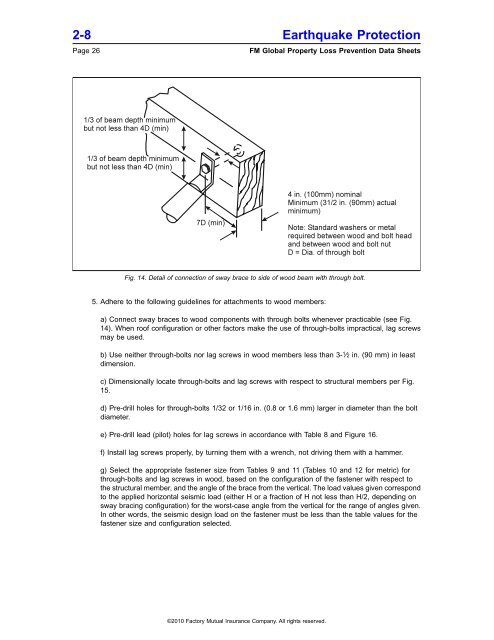
Fig. 14. Detail of connection of sway brace to side of wood beam with through bolt.<br />
5. Adhere to the following guidelines <strong>for</strong> attachments to wood members:<br />
a) Connect sway braces to wood components with through bolts whenever practicable (see Fig.<br />
14). When roof configuration or other factors make the use of through-bolts impractical, lag screws<br />
may be used.<br />
b) Use neither through-bolts nor lag screws in wood members less than 3- 1 ⁄ 2 in. (90 mm) in least<br />
dimension.<br />
c) Dimensionally locate through-bolts and lag screws with respect to structural members per Fig.<br />
15.<br />
d) Pre-drill holes <strong>for</strong> through-bolts 1/32 or 1/16 in. (0.8 or 1.6 mm) larger in diameter than the bolt<br />
diameter.<br />
e) Pre-drill lead (pilot) holes <strong>for</strong> lag screws in accordance with Table 8 and Figure 16.<br />
f) Install lag screws properly, by turning them with a wrench, not driving them with a hammer.<br />
g) Select the appropriate fastener size from Tables 9 and 11 (Tables 10 and 12 <strong>for</strong> metric) <strong>for</strong><br />
through-bolts and lag screws in wood, based on the configuration of the fastener with respect to<br />
the structural member, and the angle of the brace from the vertical. The load values given correspond<br />
to the applied horizontal seismic load (either H or a fraction of H not less than H/2, depending on<br />
sway bracing configuration) <strong>for</strong> the worst-case angle from the vertical <strong>for</strong> the range of angles given.<br />
In other words, the seismic design load on the fastener must be less than the table values <strong>for</strong> the<br />
fastener size and configuration selected.<br />
©2010 Factory Mutual Insurance Company. All rights reserved.