DS 2-8 Earthquake Protection for Water-Based Fire ... - FM Global
DS 2-8 Earthquake Protection for Water-Based Fire ... - FM Global
DS 2-8 Earthquake Protection for Water-Based Fire ... - FM Global

Create successful ePaper yourself
Turn your PDF publications into a flip-book with our unique Google optimized e-Paper software.
<strong>Earthquake</strong> <strong>Protection</strong> 2-8<br />
<strong>FM</strong> <strong>Global</strong> Property Loss Prevention Data Sheets Page 21<br />
2. For Figs. 4 or 6 using two opposing diagonal braces, each capable of resisting tension and compression<br />
(l/r = 200 or less):<br />
a) The angle from vertical <strong>for</strong> Braces A 1 and A 2 must be at least 30 degrees.<br />
b) Size and arrange both Braces A 1 and A 2 in Figures 4 or 6 to carry the larger of one-half the horizontal<br />
design load H determined in Section 2.2.1.2 or the load determined by proportional distribution of<br />
design load H to the two braces. Considering Fig. 4, if the distributed portion of the horizontal seismic<br />
load reacted by Brace A 1 is H 1 and the distributed load reacted by Brace A 2 is H 2, the load distribution<br />
can be expressed as:<br />
H 1 = (H)((tan Θ 1)/(tan Θ 1 + tan Θ 2))<br />
H 2 = (H)((tan Θ 2)/(tan Θ 1 + tan Θ 2))<br />
The distribution of loads will be similar <strong>for</strong> the arrangement shown in Fig. 6.<br />
c) These sway bracing arrangements will provide adequate resistance to vertical <strong>for</strong>ce and no additional<br />
procedures are needed in that regard.<br />
3. For tension-only sway bracing (l/r = 300 or less), which may be used when it is necessary to have longer<br />
brace members due to physical or dimensional constraints, treat as a special condition of Figs. 3 or 5<br />
by providing opposing diagonal braces (i.e., two Braces A) similar to item 1 above:<br />
a) The angle from vertical <strong>for</strong> Braces A must be at least 30 degrees.<br />
b) Size and arrange Braces A in Figs. 3 or 5 to carry, in tension, the full horizontal design load H<br />
determined in Section 2.2.1.2 since neither brace is being considered as capable of resisting<br />
compression.<br />
c) Brace B, when needed, may vary in shape and size from Braces A. Evaluate Brace B based on<br />
the net vertical uplift <strong>for</strong>ce (V F) per item 1 above.<br />
2.2.1.3.6 Select the proper method to attach the sway bracing to the structure and to the piping per the<br />
following guidelines:<br />
A. Arrange all parts and fittings in a straight line to avoid eccentric loading on any of the sway bracing<br />
components.<br />
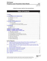
B. Connections to the structure or the piping that are not <strong>FM</strong> Approved should provide a positive<br />
mechanical attachment. These connections should also be able to be visually verified as to correct<br />
installation (see Fig. 7).<br />
Fig. 7. Special threaded pipe fitting <strong>for</strong> attachment of sway brace to structure.<br />
C. Make attachments to the structure in accordance with the following guidelines.<br />
1. Determine the shear and tension loads on the fasteners based on the fastener and sway bracing<br />
configurations illustrated in Figures 8 to 13. When using these figures, note the following:<br />
©2010 Factory Mutual Insurance Company. All rights reserved.