DS 2-8 Earthquake Protection for Water-Based Fire ... - FM Global
DS 2-8 Earthquake Protection for Water-Based Fire ... - FM Global
DS 2-8 Earthquake Protection for Water-Based Fire ... - FM Global

Create successful ePaper yourself
Turn your PDF publications into a flip-book with our unique Google optimized e-Paper software.
<strong>Earthquake</strong> <strong>Protection</strong> 2-8<br />
<strong>FM</strong> <strong>Global</strong> Property Loss Prevention Data Sheets Page 9<br />
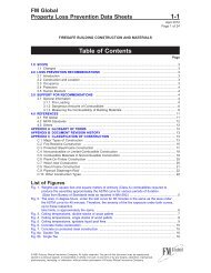
Pipe Nominal Diameter<br />
in. (mm)<br />
Table 1. Weight of <strong>Water</strong>-Filled Pipe<br />
Weight,<br />
lb/ft (N/m)<br />
Schedule 40<br />
1 (25) 2.1 (31)<br />
1-1 ⁄ 4 (32) 2.9 (43)<br />
1-1 ⁄ 2 (40) 3.6 (53)<br />
2 (50) 5.1 (75)<br />
2-1 ⁄ 2 (65) 7.9 (116)<br />
3 (80) 10.8 (159)<br />
3-1 ⁄ 2 (90) 13.5 (198)<br />
4 (100) 16.4 (241)<br />
5 (125) 23.5 (345)<br />
6 (150) 31.7 (465)<br />
8* (200) 47.7 (700)<br />
Schedule 10 and Lightwall<br />
1 (25) 1.8 (26)<br />
1-1 ⁄ 4 (32) 2.5 (37)<br />
1-1 ⁄ 2 (40) 3.0 (44)<br />
2 (50) 4.2 (62)<br />
2-1 ⁄ 2 (65) 5.9 (87)<br />
3 (80) 7.9 (116)<br />
3-1 ⁄ 2 (90) 9.8 (144)<br />
4 (100) 11.8 (173)<br />
5 (125) 17.3 (254)<br />
6 (150) 23.0 (338)<br />
8 (200) 40.1 (589)<br />
* Schedule 30<br />
2.2.1.2.3 Determine the weight (Wp) to be used <strong>for</strong> each sway brace design (or each controlling sway brace<br />
design) by including the water-filled weight of all piping within the zone of influence, defined below.<br />
A. Four-way sway bracing at risers, vertical feedmains and crossmains, and drops:<br />
1. Where the four-way sway brace restrains only the vertical pipe (e.g., an intermediate riser brace<br />
where there is no attached feedmain or crossmain) the zone of influence includes the length of the<br />
vertical pipe above and below the sway brace that is tributary to that sway brace. Use the resulting<br />
weight of pipe to determine the load to be applied in each orthogonal horizontal direction.<br />
2. Where the four-way sway brace <strong>for</strong> the vertical pipe also serves as a lateral and longitudinal sway<br />
brace <strong>for</strong> an attached horizontal pipe (e.g., feedmain or crossmain), the four-way sway brace zone<br />
of influence is determined as follows.<br />
a. In the lateral direction of the horizontal pipe, add the tributary length of vertical pipe above and<br />
below the sway brace, plus the tributary lengths of feedmain, crossmain, and branch line piping,<br />
as described in Section 2.2.1.2.3(B), located between the four-way sway brace and the first lateral<br />
sway brace on the horizontal pipe.<br />
b. In the longitudinal direction of the horizontal pipe, add the tributary length of vertical pipe above<br />
and below the sway brace, plus the tributary lengths of feedmain, crossmain, and branch line<br />
piping, as described in Section 2.2.1.2.3(C), located between the four-way sway brace and the<br />
first longitudinal sway brace on the horizontal pipe.<br />
3. The weight of the water-filled pipe <strong>for</strong> manifolded bracing design includes the total load <strong>for</strong> the two<br />
risers being braced.<br />
B. Lateral two-way sway bracing:<br />
1. For feedmains, the zone of influence includes the length of the feedmain to the left and right of the<br />
sway brace that is tributary to that brace.<br />
©2010 Factory Mutual Insurance Company. All rights reserved.