
Create successful ePaper yourself
Turn your PDF publications into a flip-book with our unique Google optimized e-Paper software.
worldmags<br />
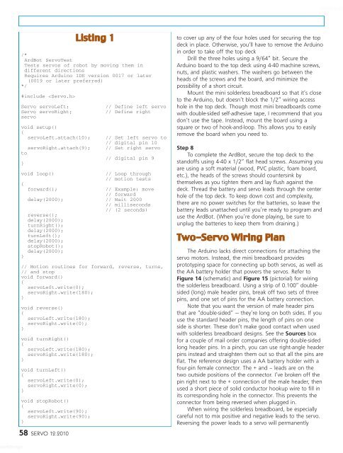
Listing 1<br />
/*<br />
ArdBot ServoTest<br />
Tests servos of robot by moving them in<br />
different directions<br />
Requires Arduino IDE version 0017 or later<br />
(0019 or later preferred)<br />
*/<br />
#include <br />
Servo servoLeft; // Define left servo<br />
Servo servoRight; // Define right<br />
servo<br />
void setup()<br />
{<br />
servoLeft.attach(10); // Set left servo to<br />
// digital pin 10<br />
servoRight.attach(9); // Set right servo<br />
to<br />
// digital pin 9<br />
}<br />
void loop() // Loop through<br />
// motion tests<br />
{<br />
forward(); // Example: move<br />
// forward<br />
delay(2000); // Wait 2000<br />
// milliseconds<br />
// (2 seconds)<br />
reverse();<br />
delay(2000);<br />
turnRight();<br />
delay(2000);<br />
turnLeft();<br />
delay(2000);<br />
stopRobot();<br />
delay(2000);<br />
}<br />
// Motion routines for forward, reverse, turns,<br />
// <strong>and</strong> stop<br />
void forward()<br />
{<br />
servoLeft.write(0);<br />
servoRight.write(180);<br />
}<br />
void reverse()<br />
{<br />
servoLeft.write(180);<br />
servoRight.write(0);<br />
}<br />
void turnRight()<br />
{<br />
servoLeft.write(180);<br />
servoRight.write(180);<br />
}<br />
void turnLeft()<br />
{<br />
servoLeft.write(0);<br />
servoRight.write(0);<br />
}<br />
void stopRobot()<br />
{<br />
servoLeft.write(90);<br />
servoRight.write(90);<br />
}<br />
58 SERVO 12.2010<br />
to cover up any of the four holes used for securing the top<br />
deck in place. Otherwise, you’ll have to remove the Arduino<br />
in order to take off the top deck<br />
Drill the three holes using a 9/64” bit. Secure the<br />
Arduino board to the top deck using 4-40 machine screws,<br />
nuts, <strong>and</strong> plastic washers. The washers go between the<br />
heads of the screws <strong>and</strong> the board, <strong>and</strong> minimize the<br />
possibility of a short circuit.<br />
Mount the mini solderless breadboard so that it’s close<br />
to the Arduino, but doesn’t block the 1/2” wiring access<br />
hole in the top deck. Though most mini breadboards come<br />
with double-sided self-adhesive tape, I recommend that you<br />
don’t use the tape. Instead, mount the board using a<br />
square or two of hook-<strong>and</strong>-loop. This allows you to easily<br />
remove the board when you need to.<br />
Step 8<br />
To complete the ArdBot, secure the top deck to the<br />
st<strong>and</strong>offs using 4-40 x 1/2” flat head screws. Assuming you<br />
are using a soft material (wood, PVC plastic, foam board,<br />
etc.), the heads of the screws should countersink by<br />
themselves as you tighten them <strong>and</strong> lay flush against the<br />
deck. Thread the battery <strong>and</strong> servo leads through the center<br />
hole of the top deck. To keep down cost <strong>and</strong> complexity,<br />
there are no power switches for the batteries, so leave the<br />
battery leads unattached until you’re ready to program <strong>and</strong><br />
use the ArdBot. (When you’re done playing, be sure to<br />
unplug the batteries to keep them from draining.)<br />
Two-Servo Wiring Plan<br />
The Arduino lacks direct connections for attaching the<br />
servo motors. Instead, the mini breadboard provides<br />
prototyping space for connecting up both servos, as well as<br />
the AA battery holder that powers the servos. Refer to<br />
Figure 14 (schematic) <strong>and</strong> Figure 15 (pictorial) for wiring<br />
the solderless breadboard. Using a strip of 0.100” doublesided<br />
(long) male header pins, break off two sets of three<br />
pins, <strong>and</strong> one set of pins for the AA battery connection.<br />
Note that you want the version of male header pins<br />
that are “double-sided” — they’re long on both sides. If you<br />
use the st<strong>and</strong>ard header pins, the length of pins on one<br />
side is shorter. These don’t make good contact when used<br />
with solderless breadboard designs. See the Sources box<br />
for a couple of mail order companies offering double-sided<br />
long header pins. In a pinch, you can use right-angle header<br />
pins instead <strong>and</strong> straighten them out so that all the pins are<br />
flat. The reference design uses a AA battery holder with a<br />
four-pin female connector. The + <strong>and</strong> – leads are on the<br />
two outside positions of the connector. I’ve broken off the<br />
pin right next to the + connection of the male header, then<br />
used a short piece of solid conductor hookup wire to fill in<br />
its corresponding hole in the connector. This prevents the<br />
connector from being reversed when plugged in.<br />
When wiring the solderless breadboard, be especially<br />
careful not to mix positive <strong>and</strong> negative leads to the servo.<br />
Reversing the power leads to a servo will permanently<br />
worldmags