
Create successful ePaper yourself
Turn your PDF publications into a flip-book with our unique Google optimized e-Paper software.
worldmags<br />
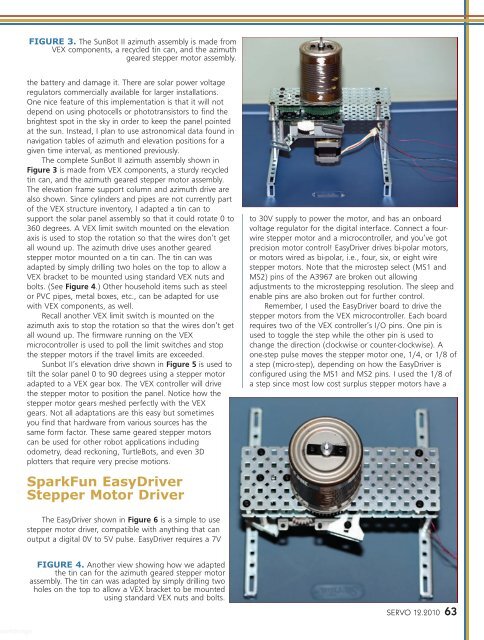
FIGURE 3. The SunBot II azimuth assembly is made from<br />
VEX components, a recycled tin can, <strong>and</strong> the azimuth<br />
geared stepper motor assembly.<br />
the battery <strong>and</strong> damage it. There are solar power voltage<br />
regulators commercially available for larger installations.<br />
One nice feature of this implementation is that it will not<br />
depend on using photocells or phototransistors to find the<br />
brightest spot in the sky in order to keep the panel pointed<br />
at the sun. Instead, I plan to use astronomical data found in<br />
navigation tables of azimuth <strong>and</strong> elevation positions for a<br />
given time interval, as mentioned previously.<br />
The complete SunBot II azimuth assembly shown in<br />
Figure 3 is made from VEX components, a sturdy recycled<br />
tin can, <strong>and</strong> the azimuth geared stepper motor assembly.<br />
The elevation frame support column <strong>and</strong> azimuth drive are<br />
also shown. Since cylinders <strong>and</strong> pipes are not currently part<br />
of the VEX structure inventory, I adapted a tin can to<br />
support the solar panel assembly so that it could rotate 0 to<br />
360 degrees. A VEX limit switch mounted on the elevation<br />
axis is used to stop the rotation so that the wires don’t get<br />
all wound up. The azimuth drive uses another geared<br />
stepper motor mounted on a tin can. The tin can was<br />
adapted by simply drilling two holes on the top to allow a<br />
VEX bracket to be mounted using st<strong>and</strong>ard VEX nuts <strong>and</strong><br />
bolts. (See Figure 4.) Other household items such as steel<br />
or PVC pipes, metal boxes, etc., can be adapted for use<br />
with VEX components, as well.<br />
Recall another VEX limit switch is mounted on the<br />
azimuth axis to stop the rotation so that the wires don’t get<br />
all wound up. The firmware running on the VEX<br />
microcontroller is used to poll the limit switches <strong>and</strong> stop<br />
the stepper motors if the travel limits are exceeded.<br />
Sunbot II’s elevation drive shown in Figure 5 is used to<br />
tilt the solar panel 0 to 90 degrees using a stepper motor<br />
adapted to a VEX gear box. The VEX controller will drive<br />
the stepper motor to position the panel. Notice how the<br />
stepper motor gears meshed perfectly with the VEX<br />
gears. Not all adaptations are this easy but sometimes<br />
you find that hardware from various sources has the<br />
same form factor. These same geared stepper motors<br />
can be used for other robot applications including<br />
odometry, dead reckoning, TurtleBots, <strong>and</strong> even 3D<br />
plotters that require very precise motions.<br />
SparkFun EasyDriver<br />
Stepper Motor Driver<br />
The EasyDriver shown in Figure 6 is a simple to use<br />
stepper motor driver, compatible with anything that can<br />
output a digital 0V to 5V pulse. EasyDriver requires a 7V<br />
FIGURE 4. Another view showing how we adapted<br />
the tin can for the azimuth geared stepper motor<br />
assembly. The tin can was adapted by simply drilling two<br />
holes on the top to allow a VEX bracket to be mounted<br />
using st<strong>and</strong>ard VEX nuts <strong>and</strong> bolts.<br />
to 30V supply to power the motor, <strong>and</strong> has an onboard<br />
voltage regulator for the digital interface. Connect a fourwire<br />
stepper motor <strong>and</strong> a microcontroller, <strong>and</strong> you’ve got<br />
precision motor control! EasyDriver drives bi-polar motors,<br />
or motors wired as bi-polar, i.e., four, six, or eight wire<br />
stepper motors. Note that the microstep select (MS1 <strong>and</strong><br />
MS2) pins of the A3967 are broken out allowing<br />
adjustments to the microstepping resolution. The sleep <strong>and</strong><br />
enable pins are also broken out for further control.<br />
Remember, I used the EasyDriver board to drive the<br />
stepper motors from the VEX microcontroller. Each board<br />
requires two of the VEX controller’s I/O pins. One pin is<br />
used to toggle the step while the other pin is used to<br />
change the direction (clockwise or counter-clockwise). A<br />
one-step pulse moves the stepper motor one, 1/4, or 1/8 of<br />
a step (micro-step), depending on how the EasyDriver is<br />
configured using the MS1 <strong>and</strong> MS2 pins. I used the 1/8 of<br />
a step since most low cost surplus stepper motors have a<br />
SERVO 12.2010 63<br />
worldmags