TRILUX Luminaires - Proljus AB
TRILUX Luminaires - Proljus AB
TRILUX Luminaires - Proljus AB

You also want an ePaper? Increase the reach of your titles
YUMPU automatically turns print PDFs into web optimized ePapers that Google loves.
Suppression choke<br />
For remote switching of outdoor lighting<br />
systems, ripple control signals are used<br />
occasionally which are superimposed on the<br />
mains voltage as high-frequency signals with<br />
frequencies ranging between 110 Hz and<br />
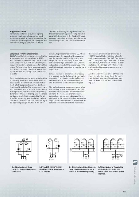
Dangerous switching resonances<br />
2000 W metal halide lamps, e.g. in spotlights,<br />
are operated on a mains voltage of 400 V.<br />
Fig. 3.4 shows a corresponding connection of<br />
three lamp circuits, which are uniformly distributed<br />
to the three phase conductors of the<br />
mains. As long as neither a phase conductor<br />
fails due to a mains incident nor a defective<br />
fuse interrupts the supply cable, this circuit<br />
is stable.<br />
As a result of unequal temperature elevation<br />
of the lamp electrodes, rectifier effects can<br />
occur during the switch-on process that almost<br />
totally suppress the current-limiting<br />
function of the choke. The consequences are<br />
short-time currents of up to 50 times the operating<br />
current, thereby causing improperly<br />
dimensioned fuses to trip (fig. 3.5). If a phase<br />
conductor, e.g. L2, is interrupted by the failure<br />
of its protecting fuse, the lamps La1 and<br />
La2 are in series and the lamp with the highest<br />
operating voltage will fail. In the other<br />
La3 D3<br />
La1 La2<br />
C3<br />
D1 D2<br />
K1 K2<br />
L1 L2 L3<br />
3.4 Distribution of three<br />
lamp circuits to three phase<br />
conductors.<br />
1600 Hz. To avoid signal degradation due to<br />
the compensation capacitor being installed<br />
parallel to the mains in the floodlight, a suppression<br />
choke has to be connected in series<br />
with the capacitor. This can be requested on<br />
site.<br />
circuits, high resonance currents I res, which<br />
depending on the capacity of the capacitor<br />
and the inductance of the choke, e.g. four<br />
lamps per circuit, can be up to 80 A and<br />
can destroy lamps and control gear, will be<br />
induced as a result of the resonances of the<br />
oscillation circuit consisting of inductors and<br />
capacitors.<br />
Similar resonance phenomena may occur,<br />
if in a circuit similar to figure 3.5, the neutral<br />
conductor N (mid-point conductor) is connected<br />
instead of the phase conductor L2<br />
and this neutral conductor is interrupted.<br />
The highest resonance currents occur when<br />
there are up to four lamps per circuit. With<br />
the centralised compensation of five lamps<br />
or more, the resonance phenomena will<br />
generally no longer occur, because the capacitance<br />
of the implemented compensation<br />
capacitors is too high to form an effective resonance<br />
circuit with the choke inductances.<br />
La1 La2<br />
Ires<br />
D1<br />
K1<br />
OFF<br />
L1 L2 L3<br />
defective<br />
D2<br />
K2<br />
3.5 Two HIT 2000 W (400 V)<br />
floodlights, where the fuse in<br />
L2 is tripped.<br />
L1<br />
L2<br />
L3<br />
D1<br />
La1<br />
K1<br />
Si Si<br />
La2<br />
D2<br />
K2<br />
Si Si<br />
L1 L2 L3<br />
La3<br />
D3<br />
K3<br />
Si Si<br />
3.6 Distribution of floodlights to<br />
three phase conductors, each<br />
feeder is protected separately.<br />
Resonances are effectively prevented in<br />
<strong>TRILUX</strong> floodlights by installing a fuse for<br />
each phase conductor (fig. 3.6). This protects<br />
the circuit against high resonance currents.<br />
If a fuse trips, the circuit it protects is interrupted<br />
and the linkage with other circuits<br />
and thus the high resonance currents are<br />
safely avoided.<br />
Another safety mechanism is a three-pole<br />
phase monitor that shuts down the entire<br />
installation if only one of the phases has<br />
failed as a result of the described causes<br />
(fig. 3.7).<br />
L1<br />
L2<br />
L3<br />
D1<br />
La1<br />
K1<br />
Si Si<br />
D2<br />
La2<br />
K2<br />
Si Si<br />
L1 L2 L3<br />
D3<br />
La3<br />
K3<br />
Si Si<br />
Ph<br />
3.7 Distribution of floodlights<br />
to three phase conductors,<br />
mains cable with 3-pole phase<br />
monitor.<br />
355<br />
Technical information