november 2010 volume 1 number 2 - Advances in Electronics and ...
november 2010 volume 1 number 2 - Advances in Electronics and ...
november 2010 volume 1 number 2 - Advances in Electronics and ...

You also want an ePaper? Increase the reach of your titles
YUMPU automatically turns print PDFs into web optimized ePapers that Google loves.
32 ADVANCES IN ELECTRONICS AND TELECOMMUNICATIONS, VOL. 1, NO. 2, NOVEMBER <strong>2010</strong><br />
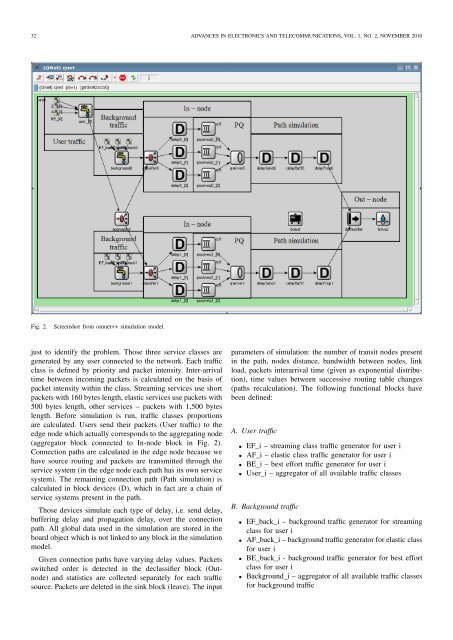
Fig. 2. Screenshot from omnet++ simulation model.<br />
just to identify the problem. Those three service classes are<br />
generated by any user connected to the network. Each traffic<br />
class is def<strong>in</strong>ed by priority <strong>and</strong> packet <strong>in</strong>tensity. Inter-arrival<br />
time between <strong>in</strong>com<strong>in</strong>g packets is calculated on the basis of<br />
packet <strong>in</strong>tensity with<strong>in</strong> the class. Stream<strong>in</strong>g services use short<br />
packetswith160byteslength,elastic servicesusepacketswith<br />
500 bytes length, other services – packets with 1,500 bytes<br />
length. Before simulation is run, traffic classes proportions<br />
are calculated. Users send their packets (User traffic) to the<br />
edge node which actually correspondsto the aggregat<strong>in</strong>gnode<br />
(aggregator block connected to In-node block <strong>in</strong> Fig. 2).<br />
Connection paths are calculated <strong>in</strong> the edge node because we<br />
have source rout<strong>in</strong>g <strong>and</strong> packets are transmitted through the<br />
service system (<strong>in</strong> the edge node each path has its own service<br />
system). The rema<strong>in</strong><strong>in</strong>g connection path (Path simulation) is<br />
calculated <strong>in</strong> block devices (D), which <strong>in</strong> fact are a cha<strong>in</strong> of<br />
service systems present <strong>in</strong> the path.<br />
Those devices simulate each type of delay, i.e. send delay,<br />
buffer<strong>in</strong>g delay <strong>and</strong> propagation delay, over the connection<br />
path. All global data used <strong>in</strong> the simulation are stored <strong>in</strong> the<br />
board object which is not l<strong>in</strong>ked to any block<strong>in</strong> the simulation<br />
model.<br />
Given connection paths have vary<strong>in</strong>g delay values. Packets<br />
switched order is detected <strong>in</strong> the declassifier block (Outnode)<br />
<strong>and</strong> statistics are collected separately for each traffic<br />
source. Packets are deleted <strong>in</strong> the s<strong>in</strong>k block (leave). The <strong>in</strong>put<br />
parameters of simulation: the <strong>number</strong> of transit nodes present<br />
<strong>in</strong> the path, nodes distance, b<strong>and</strong>width between nodes, l<strong>in</strong>k<br />
load, packets <strong>in</strong>terarrival time (given as exponential distribution),<br />
time values between successive rout<strong>in</strong>g table changes<br />
(paths recalculation). The follow<strong>in</strong>g functional blocks have<br />
been def<strong>in</strong>ed:<br />
A. User traffic<br />
• EF_i – stream<strong>in</strong>g class traffic generator for user i<br />
• AF_i – elastic class traffic generator for user i<br />
• BE_i – best effort traffic generator for user i<br />
• User_i – aggregator of all available traffic classes<br />
B. Background traffic<br />
• EF_back_i – background traffic generator for stream<strong>in</strong>g<br />
class for user i<br />
• AF_back_i–backgroundtrafficgeneratorforelastic class<br />
for user i<br />
• BE_back_i - background traffic generator for best effort<br />
class for user i<br />
• Background_i – aggregator of all available traffic classes<br />
for background traffic