november 2010 volume 1 number 2 - Advances in Electronics and ...
november 2010 volume 1 number 2 - Advances in Electronics and ...
november 2010 volume 1 number 2 - Advances in Electronics and ...

You also want an ePaper? Increase the reach of your titles
YUMPU automatically turns print PDFs into web optimized ePapers that Google loves.
PRZEMYSŁAW KREHLIK: ARE CARRIER TRANSPORT EFFECTS IMPORTANT FOR CHIRP MODELING OF QUANTUM-WELL LASERS? 65<br />
Fig. 3. Comparison of FM efficiency obta<strong>in</strong>ed from full QW model <strong>and</strong><br />
from (6).<br />
κ was trimmed to obta<strong>in</strong> a desired value of the low frequency<br />
chirp for each value of the taken capture time. It should be<br />
also po<strong>in</strong>ted out that the IM response δP (ωm)/δI(ωm) was<br />
modified each time by tak<strong>in</strong>g the actual one obta<strong>in</strong>ed from<br />
full QW rate equationsmodel.As may be noticed,averygood<br />
agreement between the chirp obta<strong>in</strong>ed from the full model <strong>and</strong><br />
from 6) was obta<strong>in</strong>ed, even for frequencies far above the laser<br />
relaxation frequency.<br />
Conclud<strong>in</strong>g, the QW laser small-signal chirp may be accuratelydeterm<strong>in</strong>edbythesimpleformulagiven<strong>in</strong>(6).However,<br />
the accurate IM response (known from any k<strong>in</strong>d of model or<br />
measured data) is crucial for good accuracy.<br />
IV. LARGE-SIGNAL CONSIDERATIONS<br />
The small-signal FM response is a basic laser property <strong>in</strong><br />
any transmission system based on frequency/phase modulation,<br />
as some coherent or dispersion-supported systems. But<br />
also <strong>in</strong> case of systems based on direct <strong>in</strong>tensity modulation,<br />
the laser chirp may be important when it <strong>in</strong>teracts with the<br />
transmission channel chromatic dispersion. This time, however,<br />
rather large signal chirp properties should be analyzed.<br />
Natural extension of the above presented small-signal considerations<br />
would be that also large-signal relation between<br />
bulklaserFM<strong>and</strong>IMmaybeadoptedtoQWlasers.Follow<strong>in</strong>g<br />
the previous strategy, the large-signal laser chirp was determ<strong>in</strong>ed<br />
by simulat<strong>in</strong>g the full QW rate equations model, <strong>and</strong><br />
nextcomparedwiththechirpobta<strong>in</strong>edfrom(5).Aspreviously,<br />
the adiabatic chirp coefficient was trimmed to obta<strong>in</strong> the best<br />
agreement with the full model. The results are illustrated <strong>in</strong><br />
Fig. 4 for various capture time values. The laser model was<br />
driven by the 200 ps long, nearly-rectangular current pulse.<br />
One may notice that the chirp obta<strong>in</strong>ed from (5) is extremely<br />
close to that result<strong>in</strong>g from the full model. Only for very large<br />
capture time, as 50 ps, some quite small delay (about 8 ps)<br />
may be observed <strong>in</strong> the chirp obta<strong>in</strong>ed from (5).<br />
AverygoodagreementoftheQWlaserchirpcharacteristics<br />
obta<strong>in</strong>ed from the full model with that determ<strong>in</strong>ed from (5)<br />
<strong>and</strong> (6) is somewhat surpris<strong>in</strong>g when we have <strong>in</strong> m<strong>in</strong>d that<br />
they are derived from the bulk laser model. However, some<br />
<strong>in</strong>tuitive explanation may be proposed. First, it should be<br />
noticed that us<strong>in</strong>g the “bulk” equations (5) <strong>and</strong> (6), the chirp<br />
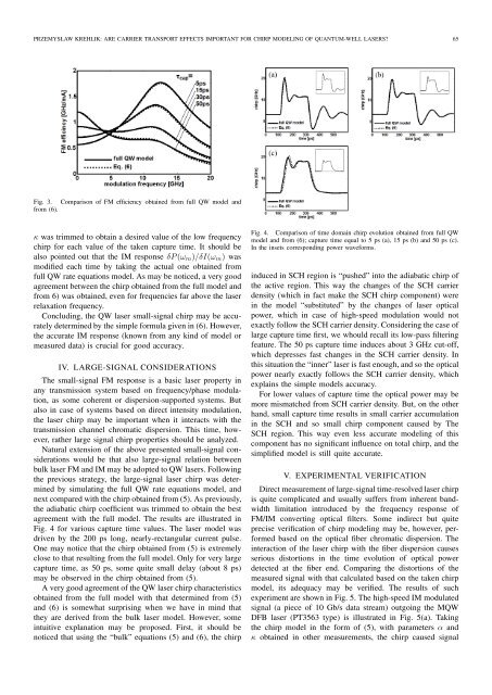
Fig. 4. Comparison of time doma<strong>in</strong> chirp evolution obta<strong>in</strong>ed from full QW<br />
model <strong>and</strong> from (6); capture time equal to 5 ps (a), 15 ps (b) <strong>and</strong> 50 ps (c).<br />
In the <strong>in</strong>sets correspond<strong>in</strong>g power waveforms.<br />
<strong>in</strong>duced <strong>in</strong> SCH region is “pushed” <strong>in</strong>to the adiabatic chirp of<br />
the active region. This way the changes of the SCH carrier<br />
density (which <strong>in</strong> fact make the SCH chirp component) were<br />
<strong>in</strong> the model “substituted” by the changes of laser optical<br />
power, which <strong>in</strong> case of high-speed modulation would not<br />
exactlyfollowtheSCH carrierdensity.Consider<strong>in</strong>gthecaseof<br />
large capture time first, we whould recall its low-pass filter<strong>in</strong>g<br />
feature. The 50 ps capture time <strong>in</strong>duces about 3 GHz cut-off,<br />
which depresses fast changes <strong>in</strong> the SCH carrier density. In<br />
thissituationthe“<strong>in</strong>ner”laserisfastenough,<strong>and</strong>so theoptical<br />
power nearly exactly follows the SCH carrier density, which<br />
expla<strong>in</strong>s the simple models accuracy.<br />
For lower values of capture time the optical power may be<br />
more mismatched from SCH carrier density. But, on the other<br />
h<strong>and</strong>, small capture time results <strong>in</strong> small carrier accumulation<br />
<strong>in</strong> the SCH <strong>and</strong> so small chirp component caused by The<br />
SCH region. This way even less accurate model<strong>in</strong>g of this<br />
component has no significant <strong>in</strong>fluence on total chirp, <strong>and</strong> the<br />
simplified model is still quite accurate.<br />
V. EXPERIMENTAL VERIFICATION<br />
Directmeasurementoflarge-signaltime-resolvedlaserchirp<br />
is quite complicated <strong>and</strong> usually suffers from <strong>in</strong>herent b<strong>and</strong>width<br />
limitation <strong>in</strong>troduced by the frequency response of<br />
FM/IM convert<strong>in</strong>g optical filters. Some <strong>in</strong>direct but quite<br />
precise verification of chirp model<strong>in</strong>g may be, however, performed<br />
based on the optical fiber chromatic dispersion. The<br />
<strong>in</strong>teraction of the laser chirp with the fiber dispersion causes<br />
serious distortions <strong>in</strong> the time evolution of optical power<br />
detected at the fiber end. Compar<strong>in</strong>g the distortions of the<br />
measured signal with that calculated based on the taken chirp<br />
model, its adequacy may be verified. The results of such<br />
experimentare shown <strong>in</strong> Fig. 5. The high-speedIM modulated<br />
signal (a piece of 10 Gb/s data stream) outgo<strong>in</strong>g the MQW<br />
DFB laser (PT3563 type) is illustrated <strong>in</strong> Fig. 5(a). Tak<strong>in</strong>g<br />
the chirp model <strong>in</strong> the form of (5), with parameters α <strong>and</strong><br />
κ obta<strong>in</strong>ed <strong>in</strong> other measurements, the chirp caused signal