Rural water supply and water demand ... - Up To - SOPAC
Rural water supply and water demand ... - Up To - SOPAC
Rural water supply and water demand ... - Up To - SOPAC

You also want an ePaper? Increase the reach of your titles
YUMPU automatically turns print PDFs into web optimized ePapers that Google loves.
<strong>SOPAC</strong> Water Resources Unit<br />
Water Dem<strong>and</strong> Management Project<br />
<strong>Rural</strong> Water Supply <strong>and</strong> Water Dem<strong>and</strong> Management<br />
REPORT OF VISIT TO VANUATU<br />
29 August - 4 September 1999<br />
By Harald Schölzel<br />
September 1999 <strong>SOPAC</strong> Miscellaneous Report 351<br />
The Water Dem<strong>and</strong> Management Project is funded by NZAID through a cash grant to<br />
the South Pacific Applied Geoscience Commission.
[3]<br />
Table of Contents<br />
SUMMARY............................................................................................................................................................................... 4<br />
INTRODUCTION................................................................................................................................................................... 6<br />
ACKNOWLEDGMENT........................................................................................................................................................ 8<br />
WATER DEMAND MANAGEMENT AND RURAL WATER SUPPLY.............................................................. 9<br />
1.1 GENERAL.......................................................................................................................................................................9<br />
1.2 WDM AND RURAL WATER SUPPLY SECTION IN VANUATU...............................................................................10<br />
THE MELE/MELE-MAAT SYSTEM............................................................................................................................13<br />
REFERENCES ......................................................................................................................................................................20<br />
APPENDIX 1: TRAVEL ITINERARY...........................................................................................................................21<br />
APPENDIX 2: MELE-MAAT SYSTEM INVENTORY............................................................................................22<br />
APPENDIX 3: DATA ACQUISITION, MANAGEMENT AND EQUIPMENT................................................27<br />
A. EQUIPMENT FOR LEAK DETECTION AND LOCATION..........................................................................33<br />
Table of Figures<br />
FIGURE 1: THE ISLAND OF EFATE AND THE LOCATION OF MELE ......................................................................................13<br />
FIGURE 2: SCHEMATIC OF THE MELE/ MELE-MAAT WATER SUPPLY SCHEME (ELEVATIONS IN M.A.S.L.)..................13<br />
FIGURE 3: PRINCIPLE OF PARTLY NON-PRESSURISED FLOW IN 150 MM PIPE (ASSUMPTION).........................................14<br />
FIGURE 4: FLOW MEASUREMENTS AT 150 MM TRUNK MAIN, MELE MAAT, VANUATU, 31 AUGUST 1999................16<br />
FIGURE 5: UNSCALED NUMERICAL MODEL OF THE MELE-MAAT SYSTEM (BASED ON PLANS FROM 1985 MADE<br />
AVAILABLE BY RWSS) SHOWING PIP SIZES AND ELEVATIONS.................................................................................17<br />
FIGURE 6: IMPOSED DEMAND ACCORDING TO AN ESTIMATED POPULATION OF 2600 APPLYING ORIGINAL DESIGN<br />
CRITERIA(13.5 L/S AVERAGE FLOW ).............................................................................................................................18<br />
FIGURE 7: STEADY STATE RESULTS SHOWING FLOW THROUGH PIPES AND AVAILABLE PRESSURE IN M .....................19<br />
Tables<br />
TABLE 1: IDENTIFIED WDM TOPICS (ROY MATARIKI, HEAD OF RURAL WATER SUPPLY DEPARTMENT , JUNE<br />
1999) .................................................................................................................................................................................12<br />
TABLE 2: DESIGN PARAMETERS FOR HYDRAULIC ANALYSIS.............................................................................................15<br />
[MR351 - Schölzel]
[4]<br />
Summary<br />
This report summarises the results <strong>and</strong> recommendations of the first field trip from 29 August<br />
to 4 September 1999, to Vanuatu, in the context of the NZODA-funded Water Dem<strong>and</strong><br />
Management Project. Its main purpose was to initiate the co-operation <strong>and</strong> determine the<br />
objectives <strong>and</strong> activities to achieve them.<br />
Prior to the trip <strong>Rural</strong> Water Supply Section (RWSS) suggested that work should focus on<br />
general WDM measures as an introduction to RWSS staff to the area. The trip coincided with<br />
the mission of a consultant funded by NZODA to assess training needs in RWSS. Therefore<br />
it was decided to wait until the release of this report before more concrete WDM actions<br />
would be planned. However, in coordination with the consultant it was decided that <strong>SOPAC</strong><br />
should start with providing training in hydraulics. It was opted that the best way attachment<br />
way to provide that would be bringing RWSS staff to the <strong>SOPAC</strong> Secretariat. It was<br />
anticipated that the attachment would be carried out from 14 October to 11 December 1999.<br />
As to the introduction to WDM different options have been discussed concentrating on data<br />
acquisition <strong>and</strong> access to designed <strong>and</strong> implemented projects as well as equipment needs,<br />
institutional arrangements <strong>and</strong> building st<strong>and</strong>ards. The following areas need to be<br />
addressed:<br />
• Though RWSS has an extraordinary well-established (hardcopy) filing system it is<br />
deemed necessary that access to all relevant information should be provided<br />
electronically preferably through a customised Geographical Information System (GIS).<br />
• Even though rural <strong>water</strong> <strong>supply</strong> schemes are small, hydraulic analysis should be carried<br />
out. Using modern analysis software would also be a first step to adequate data storage.<br />
• RWSS needs to set up a Community Participation Unit or seek assistance from other<br />
agencies (eg L<strong>and</strong> Use Department) to better involve the community in the planning,<br />
design <strong>and</strong> implementation process. That seems particularly important against the<br />
background that the community is expected to assume full ownership of the implemented<br />
project with little support from RWSS expected.<br />
• Communities should be given an active part over the entire project cycle <strong>and</strong> they should<br />
be given a choice regarding the design (eg low pressure versus high pressure, quality (eg<br />
basic treatment <strong>and</strong> service (st<strong>and</strong>pipes versus individual connections). The buzz word is<br />
Dem<strong>and</strong> Responsive Approach.<br />
• Each implemented project should be h<strong>and</strong>ed over to a <strong>water</strong> committee the community<br />
has formed during the planning, design <strong>and</strong> implementation process. (Rule: No <strong>water</strong><br />
committee -no <strong>water</strong> project)<br />
[MR351 - Schölzel]
[5]<br />
• Though community ownership seems to be the only viable solution some thoughts should<br />
be given whether regular maintenance <strong>and</strong> minor spare parts (eg washers) should be<br />
provided. This could be supported by a <strong>water</strong> committee that collects a very modest<br />
connection fee.<br />
• RWSS should purchase essential <strong>water</strong> <strong>supply</strong> system monitoring equipment, ie a<br />
portable flowmeter, pressure reader connectable to hydrants <strong>and</strong> taps, a pressure<br />
transducer to read <strong>and</strong> log <strong>water</strong> levels in tanks <strong>and</strong> reservoirs <strong>and</strong> basic leak detection<br />
tools, eg listening sticks. (see also Appendix 3 for more details.)<br />
• RWSS need to stiffen building st<strong>and</strong>ards <strong>and</strong> measure system performance right after<br />
project completion.<br />
• RWSS should develop a leakage policy that applies to all systems or at least to all<br />
system implemented from a certain size on (eg population connected). Compliance<br />
should be monitored by rotating equipment between field staff <strong>and</strong> non-compliance<br />
should trigger remedy actions in coordination with the <strong>water</strong> committee.<br />
• Though outside the scope of this trip RWSS should re-think current practice of providing<br />
<strong>water</strong> without looking (or providing) adequate sanitation.<br />
Prior to the trip, RWSS identified the <strong>water</strong> <strong>supply</strong> systems villages of Mele/Mele-Maat as a<br />
pilot area. During the trip some WDM measurements could be carried out in the respective<br />
area indicating that the Minimum Night Time Flow was around 6 l/s. Assuming a constant<br />
inflow into the tank of about 8.7 l/s (derived from measurements <strong>and</strong> calculations) <strong>water</strong><br />
losses would amount to about 68 % of the production. Even though it was not possible to<br />
confirm this result with more <strong>and</strong> longer-lasting measurements (bad weather <strong>and</strong> equipment<br />
failure due to the bad weather) current 'operation procedures' confirm (artificial) <strong>water</strong><br />
shortages (no 24 hour <strong>water</strong> <strong>supply</strong>.) These shortages are attributable not only to leakage<br />
but also to massive over-sizing of the system. (Admittedly a problem rather uncommon in the<br />
Pacific.)<br />
• The problem could be solved by installing a flow control valve at the end of 150 mm GI<br />
trunk main.<br />
[MR351 - Schölzel]
[6]<br />
Introduction<br />
In the past, development projects in the <strong>water</strong> <strong>supply</strong> sector have mainly concentrated on the<br />
upgrading or extension of existing <strong>water</strong> <strong>supply</strong> hardware. This <strong>supply</strong>-driven approach has<br />
proved to be very costly for both the donor <strong>and</strong> the receiving country <strong>and</strong> has not lead to a<br />
safe <strong>water</strong> <strong>supply</strong> even for the bigger urban centres in most of the Pacific Isl<strong>and</strong>s Countries<br />
(PIC). Most <strong>water</strong> <strong>supply</strong> systems operate at the edge of collapse not because that there is<br />
not enough <strong>water</strong> available at the source of abstraction, but because <strong>water</strong> <strong>supply</strong> systems in<br />
PIC lose more <strong>water</strong> through leakage <strong>and</strong> wastage than they actually deliver to customers.<br />
The patchy design of these distribution systems render not only the technical design of many<br />
aid projects technically questionable but also makes the management <strong>and</strong> operation by the<br />
local <strong>water</strong> authority very difficult. With more pressure on very limited resources, many PIC<br />
have realised that the key towards sustainability lies, not necessarily, in costly infrastructure<br />
extension but more in the sound management of the <strong>water</strong> <strong>supply</strong> system. This trend has<br />
been enforced with the appearance of institutional strengthening projects in the <strong>water</strong> sector,<br />
mainly funded by AusAID, that concentrate on building national capacity rather than giving<br />
away hardware.<br />
Generally speaking, <strong>water</strong> leakage <strong>and</strong> wastage are the main reasons for <strong>water</strong> problems in<br />
Pacific Isl<strong>and</strong> Countries <strong>and</strong> previous initiatives to resolve this problem have been limited to<br />
unsystematic <strong>and</strong> isolated projects. This often resulted in the only temporary set-up of leak<br />
detection units, instructed <strong>and</strong> trained over a very limited period by consultants. From time to<br />
time, multi-international donors fund some isolated activity to reduce leakage with little or no<br />
follow-up. Though a good part of the project is aimed at this particular problem of <strong>water</strong><br />
conservation <strong>water</strong> dem<strong>and</strong> management (WDM) st<strong>and</strong>s for much more than that. It is a<br />
holistic approach towards controlling the <strong>water</strong> <strong>supply</strong> system <strong>and</strong> making fully-informed<br />
decisions. It includes preventative maintenance as well as setting up performance-monitoring<br />
devices or the zonation of the system by districts <strong>and</strong> pressure sub-zones. Economic <strong>and</strong><br />
environmental issues influence the degree to which leakage detection program will be carried<br />
out <strong>and</strong> are part of WDM. After all, <strong>water</strong> pricing is an important tool for influencing consumer<br />
dem<strong>and</strong> together with Public Awareness Campaigns. In short:<br />
'Water Dem<strong>and</strong> Management involves the adoption of policies or investment by a <strong>water</strong> utility<br />
to achieve efficient <strong>water</strong> use by all members of the community. (White, 1998) 1 '<br />
In the past, <strong>SOPAC</strong> managed <strong>and</strong> implemented a <strong>water</strong> dem<strong>and</strong> management (WDM)<br />
project in the Pacific funded by the Republic of China. The current WDM project is funded by<br />
the New Zeal<strong>and</strong> Overseas Development Assistance (NZODA). The current project aims to<br />
implement the recommendations <strong>and</strong> conclusions of a regional meeting with 25 participants<br />
from 13 countries on Water Dem<strong>and</strong> Management held in Nadi from the 21 st to the 26 th of<br />
June 1999. It comprises Technical Assistance with the assessment of <strong>water</strong> losses,<br />
generation of 'as-built' electronic maps (inventories), generation of hydraulic network models,<br />
1 White, S., (1998), Wise Water management: A dem<strong>and</strong> Management Manaual for Water Utilities, Institute for<br />
Sustainable Future, Universitty of Technology, Sydney, Research Report No. 86.<br />
[MR351 - Schölzel]
[7]<br />
leak detection, management problems <strong>and</strong> on-the-job-training as well as training<br />
attachments at the <strong>SOPAC</strong> Secretariat in Suva, Fiji - a genuine approach to transfer<br />
knowledge.<br />
The WDM project should be seen as supplementing ongoing country initiatives.<br />
[MR351 - Schölzel]
[8]<br />
Acknowledgment<br />
The <strong>SOPAC</strong> Secretariat thanks NZODA for their financial support to its Water Dem<strong>and</strong><br />
Management initiative.<br />
The author wishes to thank all staff of Vanuatu <strong>Rural</strong> Water Supply for their support during<br />
the field mission, especially Mr. Roy Matariki, Head of the Department.<br />
[MR351 - Schölzel]
1.1 General<br />
[9]<br />
Water Dem<strong>and</strong> Management <strong>and</strong> <strong>Rural</strong> Water Supply<br />
Traditionally WDM projects focus on urban <strong>water</strong> <strong>supply</strong> systems apparently for very obvious<br />
reasons:<br />
• Urban <strong>water</strong> supplies are run by a more or less professionally-organised agency/ utility<br />
hence there is a defined recipient <strong>and</strong> partner for any project.<br />
• The size of most urban <strong>water</strong> <strong>supply</strong> systems generate significant distribution costs <strong>and</strong><br />
in some cases also significant revenues. That allows for relatively straightforward costbenefit-analysis<br />
of WDM measures.<br />
• Urban <strong>water</strong> <strong>supply</strong> systems usually, <strong>and</strong> rather unfortunately, also 'generates' significant<br />
leakage levels making it easier to achieve success.<br />
• Water <strong>supply</strong> problems in urban areas rapidly affect a large number of people making it<br />
more pressing to the <strong>water</strong> utility/ Government to overcome or anticipate such problems.<br />
• Influential people, locals or foreigners, usually reside in urban areas <strong>and</strong> push for<br />
providing an efficient <strong>and</strong> safe <strong>water</strong> <strong>supply</strong> (<strong>and</strong> sanitation).<br />
• Urban areas usually offer a more receptive audience for public awareness campaigns<br />
since they can be considered pure cash-economies.<br />
<strong>Rural</strong> <strong>water</strong> <strong>supply</strong> systems, in contrast, present entirely different problems:<br />
• They are small often with a design flow lower than 1 l/s.<br />
• Design st<strong>and</strong>ards are rudimentary <strong>and</strong> systems are often fragmented since there is little<br />
control over who's connecting <strong>and</strong> how the connection is being done.<br />
• They are owned by the community <strong>and</strong> managed by a <strong>water</strong> committee (if at all<br />
implemented) which rarely has the expertise, skills <strong>and</strong> financial resources to do so.<br />
• Running costs are mostly insignificant hence rarely seem to justify complex WDM<br />
measures/ projects.<br />
• <strong>Rural</strong> <strong>water</strong> <strong>supply</strong> means that there are many <strong>water</strong> <strong>supply</strong> systems often difficult to<br />
reach.<br />
All these points seem to impede WDM measures <strong>and</strong> ideas which are more consequently<br />
applied to urban <strong>water</strong> <strong>supply</strong> schemes. However, there are important considerations that<br />
WDM should play a bigger role in rural <strong>water</strong> <strong>supply</strong>.<br />
[MR351 - Schölzel]
[10]<br />
In general, economies of scale apply to <strong>water</strong> <strong>supply</strong> schemes. That basically means that<br />
costs to provide one unit of <strong>water</strong> to consumers decrease 2 with the amount of units<br />
produced. Hence, it is relatively more expensive to provide <strong>water</strong> to a person that lives in a<br />
small community than to a city dweller. However, very basic (<strong>and</strong> often insufficient) design<br />
st<strong>and</strong>ards (low design flow, very basic development of <strong>water</strong> intakes, small pipe sizes, few<br />
control devices, low building st<strong>and</strong>ards) provide means to reduce costs for rural <strong>water</strong> <strong>supply</strong><br />
systems. On the other h<strong>and</strong> this leads in some cases to problems with the <strong>water</strong> <strong>supply</strong> from<br />
the very beginning; after all losing e.g 0.5 l/s in the form of leakage out of a system that was<br />
designed 3 to provide 1 l/s average flow means that 50% would be lost. That would certainly<br />
create problems for most village schemes.<br />
Even more important seems to be the fact that in many cases villagers substantially<br />
contribute to their <strong>water</strong> <strong>supply</strong> schemes either financially (two-third-one-third principle) or in<br />
the form of (unskilled) labour or both. These investments into safe <strong>water</strong> deserve the same<br />
protection as that given to urban schemes, if not more. Additionally the perceived lack of<br />
<strong>water</strong> in village <strong>supply</strong> schemes leads regularly to applications to extend the systems either<br />
with Government or other donor support. Very little attention is usually given to simply look<br />
into the system <strong>and</strong> analyse its performance <strong>and</strong> the reason for any possible underperformance<br />
although many such problems could be avoided through WDM.<br />
Finally, WDM in rural areas finds its justification with the apparent increase of droughts not<br />
as an emergency tool but as a relatively simple preventative means to provide safe <strong>water</strong> to<br />
the community.<br />
1.2 WDM <strong>and</strong> <strong>Rural</strong> Water Supply Section in Vanuatu<br />
The need to further improve the <strong>Rural</strong> Water Supply Section in Vanuatu has been recognised<br />
widely. There are several studies 4 <strong>and</strong> projects that detail the problems, re-organisation <strong>and</strong><br />
training needs as well as recommend solutions <strong>and</strong> strategies to overcome them. However,<br />
implementation lags far behind.<br />
2 This principal applies not 'forever' since it usually becomes increasingly expensive to abstract <strong>water</strong> but this<br />
point may be ignored in the present case.<br />
3 And probably does not yield much more at all because the easiest to access source has been captured for cost<br />
<strong>and</strong> convenience considerations<br />
4 Eg Montgomery & Watson, 1997 <strong>and</strong> Mills, 1999 (not yet published). The reader is referred to these reports.<br />
[MR351 - Schölzel]
[11]<br />
During the afore-mentioned WDM workshop, some time was spent on developing an<br />
immediate/medium-term Action Plan. Table 1 lists the topics the <strong>Rural</strong> Water Supply Section<br />
has identified as their main concern (<strong>SOPAC</strong>, 1999). This list was used to offer a choice of<br />
activities <strong>SOPAC</strong> could provide assistance with. After some discussion it was agreed that<br />
work during this mission should concentrate on the Mele/Mele-Maat <strong>water</strong> <strong>supply</strong> system as<br />
a pilot project to demonstrate WDM principles <strong>and</strong> methods regarding data acquisition,<br />
storage <strong>and</strong> hydraulic analysis.<br />
[MR351 - Schölzel]
[12]<br />
Table 1: Identified WDM topics (Roy Matariki, Head of <strong>Rural</strong> Water Supply Department, June 1999)<br />
<strong>To</strong>pic Description of Activity Time frame Responsibility Identified Training<br />
Capital Cost Include in budget to cover for metering on pilot<br />
projects only<br />
Hydraulic Analysis Review current designing <strong>and</strong> design to<br />
accommodate basic metering<br />
Feb-00 Dept of Water Resources<br />
Next financial year (July 99 - July 2000) Current <strong>and</strong> probable assistance,<br />
UNELCO, Aid Agencies<br />
[MR351 - Schölzel]<br />
Needs<br />
From <strong>SOPAC</strong> - for<br />
direction<br />
Data Organising Start collecting data into include budget ASAP Dept of Water Resources Mines Dept with <strong>SOPAC</strong><br />
Leakage Control Create community awareness ASAP after approval of budget Dept of Water Resources Maintenance <strong>and</strong> cultural<br />
awareness unit<br />
Reservoir test Measure flow test Monthly Dept of Water Resources, PWD As above<br />
Pipe locating Through project files Next financial year (July 99 - July 2000) Dept of Water Resources, PWD As above<br />
Pipe locating On-site locating of pipes Next financial year (July 99 - July 2000) Dept of Water Resources, PWD As above<br />
District Metering Identify two pilot projects January 2000 As above Basics<br />
District Metering Locate areas needed to be metered i.e. zoning January 2001 As above Basics<br />
Leakage Policy in<br />
Corporate Plan<br />
Include this into our program for major rural<br />
systems i.e. gravity <strong>and</strong> pumps<br />
Next financial year (July 99 - July 2000) <strong>To</strong> persuade Management to provide<br />
Re-engineering Provide policy to cater for the changes Next financial year (July 99 - July 2000) Engineering <strong>and</strong> formulation unit to<br />
funding<br />
include into design<br />
Seek aid funding for the<br />
specific training<br />
Engineer needs to train<br />
other personnel
[13]<br />
The Mele/Mele-Maat System<br />
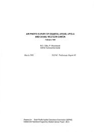
The villages Mele <strong>and</strong> Mele-Maat are situated Northwest of Port Vila on the Isl<strong>and</strong> of Efate. The<br />
villages are of semi-urban in nature with a current population of about 2,600. Figure 1 shows their<br />
location as "Mele".<br />
Figure 1: The isl<strong>and</strong> of Efate <strong>and</strong> the location of Mele<br />
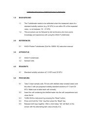
The existing Mele/Mele-Maat <strong>water</strong> <strong>supply</strong> system (Figure 2)consists of a surface-<strong>water</strong> intake, a 80<br />
mm PE main from the source to the tank (960 m), two interconnected 120 m 3 tanks, a 80 mm GI<br />
main to Mele-Maat (250 m) <strong>and</strong> a 150 mm GI/PVC main to Mele (2000 m).<br />
Source:<br />
Elevation: 125 m<br />
Main:<br />
Length: 960 m<br />
Type: 80 mm, PE<br />
Flow Rate: 8.7 l/s<br />
Main:<br />
Length: 2100 m<br />
Type: 150 mm, PE,GI<br />
Tanks:<br />
Storage: 2 x 120 m 3<br />
Elevation: 125 m<br />
Main:<br />
Length: 500 m<br />
Type: 80 mm,PVC, GI<br />
Mele System:<br />
Population: 2000<br />
Elevation: ~ 5 m<br />
[MR351 - Schölzel]<br />
Mele-Maat System:<br />
Population: 600<br />
Elevation:~ 10 m<br />
Figure 2: Schematic of the Mele/Mele-Maat <strong>water</strong> <strong>supply</strong> scheme (Elevations in m.a.s.l.)
[14]<br />
The design population for Mele was 2,000 <strong>and</strong> Mele-Maat 600. Design dem<strong>and</strong> was assumed to be<br />
200 l/c/d. Both systems can be operated independently with no interconnection between them<br />
except the common tank they rely on. Inflow into tank has been measured <strong>and</strong> calculated <strong>and</strong> is in<br />
the range of about 8.7 l/s <strong>and</strong> can assumed to be constant over time.<br />
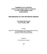
Currently the system experiences problems with providing <strong>water</strong> over 24 hours. Flow measurements<br />
(Figure 4) at the 150 mm main pipe to Mele indicate that the Minimum Night Time Flow (MNTF) is<br />
about 6 l/s. That suggests that leakage amounts to about 68 % of the daily production in the Mele<br />
system alone. Further flow measurements were not possible because of equipment breakdown due<br />
to bad weather.<br />
The current <strong>water</strong> <strong>supply</strong> problems are attributable to the high level of leakage as well to a gross<br />
over-design(!!!) of the entire system. The Mele system has been designed for a maximum flow of<br />
30 l/s, the Mele-Maat system for 9 l/s 5 . That resulted in pipe diameters far to big to allow for a<br />
pressurised pipe flow <strong>and</strong> a rapid drain-out of the tank. The pipe slope over the first, say, 150 m after<br />
the tank is about 70 degrees accelerating the <strong>water</strong> that leaves the tank to an extent that creates an<br />
open channel flow within the pipe. That on the other h<strong>and</strong> avoids that the full head between the tank<br />
<strong>and</strong> the Mele system (65 m - 5 m = 60 m) becomes effective. Figure 3 describes the problem.<br />
Pressurised flow<br />
Water surface, no pressurised flow<br />
[MR351 - Schölzel]<br />
Effective Head = ?? m<br />
Theoretical Head = 65 m<br />
Figure 3: Principle of partly non-pressurised flow in 150 mm pipe (assumption)<br />
This assumption was indirectly confirmed by flow measurements 6 . This problem can be resolved by<br />
installing a flow control valve in the flat part of the 150 mm main right after the slope 7 .<br />
5 It is a mystery where these design criteria have been derived from.<br />
6 The portable flowmeter could not detect valid condition to take measurements. This usually means, after excluding other<br />
error sources, that the flow not pressurised or too turbulent - in this particular case probably both.<br />
7 Currently the flow is regulated by a gate valve at the outlet of the tank effectively limiting the outflow of the tank but<br />
aggravating the described pressure problem.
[15]<br />
A full hydraulic analysis based on the original system design <strong>and</strong> the measurements have been<br />
carried out. Table 2 summarises the applied design criteria. These more modest criteria follow<br />
st<strong>and</strong>ard procedures <strong>and</strong> are much more in line with the actual production of the source: 8.7 l/s as<br />
production versus 6.02 l/s average flow, 7.82 l/s max. average daily flow 8 .<br />
Table 2: Design parameters for hydraulic analysis<br />
Village Mele Mele Maat <strong>To</strong>tal<br />
Population No. 2000 600 2600<br />
Dem<strong>and</strong> Daily [l/capita/day] 200 200 400<br />
<strong>To</strong>tal Dem<strong>and</strong> [l/day] 400000 120000 520000<br />
m3/day 400 120 520<br />
Average Flow [l/s] 4.63 1.39 6.02<br />
[m3/hour] 16.67 5.00 21.67<br />
Daily Peak Factor [-] 1.30 1.30<br />
Max Aver. Daily Flow [l/s] 6.02 1.81 7.82<br />
Hourly Peak Factor [-] 2.40 2.40<br />
Max.Hourly Flow [l/s] 14.44 4.33 18.78<br />
Even the max. hourly Flow of 18.78 l/s does not come anywhere near the 37.8 l/s flow applied in the<br />
original design.<br />
The results of the hydraulic analysis have been summarised in Figure 5 to Figure 7 <strong>and</strong> Appendix 2.<br />
They show that, assuming fully pressurised flow, pressure would be at all times in the range of 55 m<br />
posing a hazard to a rather usually fragile house connection. On the other h<strong>and</strong> high pressure during<br />
static or semi-static conditions (pipes fill fully during the night) yields a good explanation for the high<br />
leakage levels in the system. However, since it is unlikely that the 150 mm pipe to Mele ever fills fully<br />
the hydraulic analysis provides only limited information unless more is known about the real pressure<br />
levels in the system. It is anticipated that this information can be gathered within the next two<br />
months.<br />
8 This base flow would be used to design the tank applying specific local dem<strong>and</strong> pattern the flow.<br />
[MR351 - Schölzel]
Flow [l/s]<br />
12<br />
10<br />
8<br />
6<br />
4<br />
2<br />
0<br />
[16]<br />
Flow Rate Mele Maat <strong>water</strong> Supply System, Efate, Vanuatu<br />
Estimated Minimum Night Time Flow: 5.64 l/s<br />
15:30:16 99-08-31<br />
15:46:16 99-08-31<br />
16:02:16 99-08-31<br />
16:18:16 99-08-31<br />
16:34:16 99-08-31<br />
16:50:16 99-08-31<br />
17:06:16 99-08-31<br />
17:22:16 99-08-31<br />
17:38:16 99-08-31<br />
17:54:16 99-08-31<br />
18:10:16 99-08-31<br />
18:26:16 99-08-31<br />
18:42:16 99-08-31<br />
18:58:16 99-08-31<br />
19:14:16 99-08-31<br />
19:30:16 99-08-31<br />
19:46:16 99-08-31<br />
20:02:16 99-08-31<br />
20:18:16 99-08-31<br />
20:34:16 99-08-31<br />
20:50:16 99-08-31<br />
21:06:16 99-08-31<br />
21:22:16 99-08-31<br />
21:38:16 99-08-31<br />
21:54:16 99-08-31<br />
22:10:16 99-08-31<br />
22:26:16 99-08-31<br />
22:42:16 99-08-31<br />
22:58:16 99-08-31<br />
23:14:16 99-08-31<br />
23:30:16 99-08-31<br />
23:46:16 99-08-31<br />
0:02:16 99-09-01<br />
Figure 4: Flow measurements at 150 mm trunk main, Mele Maat, Vanuatu, 31 August 1999<br />
Time<br />
[MR351 - Schölzel]
[17]<br />
Figure 5: Unscaled numerical model of the Mele-Maat System (based on plans from 1985 made available by RWSS) showing pip sizes <strong>and</strong><br />
elevations.<br />
[MR351 - Schölzel]
Figure 6: Imposed dem<strong>and</strong> according to an estimated population of 2600 applying original design criteria(13.5 l/s average flow)<br />
[18]<br />
[MR351 - Schölzel]
Figure 7: Steady state results showing flow through pipes <strong>and</strong> available pressure in m<br />
[19]<br />
[MR351 - Schölzel]
[20]<br />
References<br />
Montgomery & Watson (1997), Master Plan Studies for Vanuatu & New Zeal<strong>and</strong><br />
Mills, G. (1997), Training needs of the Department of Geology, Mines & Water Resources,<br />
New Zeal<strong>and</strong><br />
[MR351 - Schölzel]
Sunday, 29 August - Suva - Nadi - Port Vila<br />
[21]<br />
Appendix 1: Travel Itinerary<br />
Saturday, 4 September - Port Vila - Nadi - Suva<br />
[MR351 - Schölzel]
[22]<br />
Appendix 2: Mele-Maat System Inventory<br />
[MR351 - Schölzel]
[23]<br />
[MR351 - Schölzel]
[24]<br />
[MR351 - Schölzel]
[25]<br />
[MR351 - Schölzel]
[26]<br />
[MR351 - Schölzel]
[27]<br />
Appendix 3: Data Acquisition, Management <strong>and</strong> Equipment<br />
This section has been provided by Malcolm Farley, WHO Consultant <strong>and</strong> Specialist in<br />
Water Dem<strong>and</strong> Management.<br />
[MR351 - Schölzel]
A. General<br />
Operational Data Management (DM) involves<br />
• - the acquisition of data<br />
[28]<br />
• - the transmission of data from local sites to operations<br />
• - the archiving <strong>and</strong> presentation of data <strong>and</strong> reports<br />
Such a system requires;<br />
• - a sensor, for data gathering at source<br />
• - data logging equipment, for local site storage<br />
• - a communication system, for transferring data to the operator<br />
• - software, for archiving <strong>and</strong> presenting data<br />
Sensors<br />
A typical monitoring system will include sensor capacity <strong>and</strong> interface leads for a range of DMA<br />
meters <strong>and</strong> pressure monitors;<br />
• - digital <strong>and</strong> analogue (e.g. 4-20mA, 0-1V) output<br />
• - specific pulse heads for helix meters (e.g Kent PD100 pulse disk bidirectional sensor)<br />
• - other proprietary sensors (HRP, LRP, reed switch, BPG20)<br />
• - optical sensors<br />
• - magnetic sensors<br />
• - pressure <strong>and</strong> depth transducers<br />
Data Capture<br />
Data capture requires the use of pulse generators, pulse counters <strong>and</strong> data loggers (portable or<br />
with telemetry) to capture data from the DMA meter.<br />
[MR351 - Schölzel]
Pulse generators.<br />
[29]<br />
These are units attached to the register of a mechanical meter to provide a pulse output, in<br />
effect creating an electromechanical meter. Kent Meters <strong>supply</strong> the LRP (10 pulses/rev) <strong>and</strong><br />
HRP (100 pulses/rev) units which are attached to the range of their helix meters. They are solid<br />
state units which have replaced the Kent PU10 <strong>and</strong> PU100. Wessex Electronics also <strong>supply</strong> a<br />
solid state unit, the "Metermate", which will interface with any of the Kent helix meter range <strong>and</strong><br />
any data logger.<br />
Pulse counters/low cost data loggers<br />
These units are usually low cost single or dual channel data loggers used to record pulse<br />
output signals. Their main use is as a temporary installation data logger to record night flows<br />
over several nights as an indicator of leakage prior to a full data logging exercise. They are also<br />
suitable for household <strong>and</strong> non-household dem<strong>and</strong> logging. Some loggers can be mounted<br />
directly onto helix meters, eliminating the need for a pulse generator.<br />
An outline specification for this type of logger is as follows;<br />
• logging interval from 6 seconds to 60 minutes<br />
• 120 days memory at 15 minute intervals<br />
• submersible to IP68<br />
• temperature -10 deg C to + 60 deg C<br />
• digital input to support;<br />
• pressure input facility to support;<br />
• RS232 interface<br />
range of mechanical helix meters<br />
electromechanical insertion probes<br />
EM insertion probes<br />
contact closure pulse units<br />
electronic pulse units used with a range of mechanical<br />
meters<br />
0-25 bar for distribution monitoring sensors<br />
0-350 millibar for reservoir depth sensors<br />
range of electrical inputs<br />
[MR351 - Schölzel]
Data loggers<br />
[30]<br />
Data loggers are used by all <strong>water</strong> companies to regularly monitor DMA flows on a 24-hour<br />
basis. They are dual or multi-channel, designed for permanent installation if required.<br />
An outline specification for this type of logger is as follows;<br />
• - logging interval from 1 second to 24 hours<br />
• - 380 days memory at 15 minute intervals<br />
• submersible to IP68<br />
• shock proof from1.0m drop<br />
• temperature -10 deg C to + 60 deg C<br />
• digital input to support;<br />
• pressure input facility to support;<br />
• communications;<br />
• battery life 10 years (lithium chloride)<br />
• alarm capacity<br />
range of mechanical helix meters<br />
electromechanical insertion probes<br />
EM insertion probes<br />
contact closure pulse units<br />
electronic pulse units used with a range of mechanical<br />
meters<br />
0-25 bar for distribution monitoring sensors<br />
0-350 millibar for reservoir depth sensors<br />
range of electrical inputs<br />
software selectable,<br />
local via RS232 interface, telemetry options<br />
It should be noted that some manufacturers <strong>supply</strong> data loggers with a sufficiently high<br />
specification to serve as both pulse counters <strong>and</strong> permanent data loggers. It is recommended<br />
that practitioners use the specifications above as a guide for selecting from a manufacturer the<br />
data logger suitable for the purpose.<br />
All logger types should be compatible with the range of European <strong>and</strong> North American<br />
flowmeters which are now being used by the UK <strong>water</strong> industry for DMA monitoring. They<br />
should able to receive digital <strong>and</strong> analogue signals so that they can also be used for pressure<br />
monitoring <strong>and</strong> level sensing, <strong>and</strong> with temporary insertion/clamp-on meter installations.<br />
[MR351 - Schölzel]
Communications<br />
Data is communicated from site by;<br />
[31]<br />
• site interrogation via a laptop or palmtop (e.g. Psion) computer<br />
• return of the data logger to the office for PC interrogation<br />
• telemetry, either via PSTN, GSM or Paknet<br />
Telemetry data logger<br />
Telemetry loggers should be capable of linking to a range of communication systems. In<br />
addition to the data capture specifications listed in 3.3.2, they should have the option of;<br />
• internal PSTN modem<br />
• GSM (Cellnet or Vodaphone) module<br />
• Paknet radio-pad<br />
An initiative by one <strong>water</strong> company (reported in "Water Bulletin" - January 1998), involves<br />
connection via Vodaphone's wireless data network, using 1200 "Paknet Radio-Pad"<br />
connections (modem equivalent). It is claimed that purchase <strong>and</strong> installation of the radio<br />
network will cost 10% of a fixed line system, which can cost up to £3000.00 for a single<br />
connection. Line rental is also less (50% of a st<strong>and</strong>ard telecom line). The monitoring system<br />
uses ABB Kent-Taylor meters <strong>and</strong> a mix of Radcom <strong>and</strong> ABB data loggers. The antennae are<br />
housed in polyethylene pillars.<br />
Individual manufacturers can provide more detailed specifications for their monitoring<br />
equipment. Leading manufacturers are listed in Appendix 1.<br />
Monitoring software <strong>and</strong> information systems<br />
Software is required to arrange logged data into a form where it can be used for analysing <strong>and</strong><br />
interpreting total night flow losses in each DMA.<br />
Software for calculating <strong>and</strong> displaying total night flow losses is usually provided by logger<br />
manufacturers. Companies either use manufacturers' software, commission consultants, or use<br />
their own in-house facilities for writing software for leakage reports <strong>and</strong> for DMA management.<br />
Typical information required for these reports are;<br />
• DMA details<br />
• DMA night flow data <strong>and</strong> aggregated flows<br />
• total night flow losses in each DMA<br />
[MR351 - Schölzel]
• estimated leakage <strong>and</strong> priority DMAs<br />
• company leakage figure<br />
• historic burst records<br />
• repair times <strong>and</strong> cost<br />
[32]<br />
DMA data identifies unreported bursts, from sudden changes in volume, <strong>and</strong> cumulative<br />
leakage, from a combination of small bursts <strong>and</strong> weeping joints <strong>and</strong> fittings.<br />
In a telemetered DMA system night flow data can be received <strong>and</strong> analysed regularly. This<br />
enables changes in the night flow of each DMA to be quickly identified, reducing awareness<br />
time. When compared with previous readings <strong>and</strong> with other DMAs, it enables the leakage<br />
control team to prioritise inspection. The logger software typically contains an "error table"<br />
which identifies those DMAs where night flows have increased above a pre-set alarm level.<br />
The leakage control team is able to scan the error table daily to identify unreported bursts, or in<br />
response to poor pressure complaints to confirm a reported burst.<br />
Software should be Windows-based, <strong>and</strong> should provide facilities for graphing <strong>and</strong> report<br />
generation to prioritise work.<br />
[MR351 - Schölzel]
[33]<br />
A. EQUIPMENT FOR LEAK DETECTION AND LOCATION<br />
A Review of the Equipment<br />
Equipment Comments / Application Limitations<br />
‘Basic’ Listening<br />
Stick<br />
‘Electronic’<br />
Listening Stick<br />
Electronic ground<br />
microphone<br />
Electronic ground<br />
microphone with<br />
sound frequency<br />
filters<br />
Rudimentary sounding of SVs,<br />
FHs, MSTs etc.<br />
General sounding of SVs, FHs,<br />
MSTs etc. Better than ‘Basic’<br />
Stick due to sound<br />
amplification. Is sometimes<br />
used to confirm ‘best leak<br />
sound’ position after<br />
correlation.<br />
More sensitive than the<br />
electronic stick, generally used<br />
to confirm ‘best leak sound’<br />
after correlation, powerful<br />
enough to listen to leak sounds<br />
through ‘made roadways’. Can<br />
be used for general sounding<br />
with a probe screwed into<br />
microphone.<br />
As sensitive as the ground<br />
microphone with the added<br />
advantage of the inspector<br />
being able to adjust filters <strong>and</strong><br />
remove some unwanted<br />
sounds. Generally used to<br />
confirm ‘best leak sound’ after<br />
correlation. Powerful enough<br />
to listen to leak sounds through<br />
‘made roadways’. Can be used<br />
for general sounding with a<br />
probe screwed into<br />
microphone.<br />
[MR351 - Schölzel]<br />
Some smaller leak sounds<br />
may go undetected (good<br />
ear required by inspector).<br />
Few limitations, generally<br />
useful part of the<br />
inspectors ‘tool kit’.<br />
Better than ‘Basic’ Stick,<br />
not as good as ground<br />
microphone (see below).<br />
More ‘cumbersome’ to<br />
use than listening stick.<br />
Some inspectors do not<br />
like to use microphones,<br />
they prefer the electronic<br />
stick.<br />
More ‘cumbersome’ to<br />
use than listening stick.<br />
Some inspectors do not<br />
like to use microphones,<br />
they prefer the electronic<br />
stick
[34]<br />
Equipment Comments / Application Limitations<br />
Acoustic<br />
Detection Loggers<br />
‘Stores’ sounds within the<br />
distribution system usually<br />
between 02:00 <strong>and</strong> 04:00.<br />
Loggers are set up <strong>and</strong><br />
downloaded using a PC. Leak<br />
sounds are identified by the<br />
‘range’ of sounds recorded by<br />
the logger. Useful for areas<br />
where normal leak location<br />
activities cannot be used.<br />
Step Test Unit Mobile Advanced Step Tester<br />
(MAST) system. Used for<br />
remote monitoring of flows<br />
whilst carrying out step tests<br />
within distribution networks.<br />
Allows almost instant results<br />
of valve closure leading to<br />
minimum disruption to<br />
customers. Leak location<br />
activity can be carried out<br />
quickly rather than waiting for<br />
‘office based’ analysis of step<br />
tests using data loggers.<br />
Leak Noise<br />
Correlators -<br />
various<br />
Can also be used for remote<br />
monitoring of pressure during<br />
valve closure (critical node<br />
monitoring whilst setting up<br />
PMAs or DMAs).<br />
Used for general ‘surveying’ of<br />
lengths of main for leak sounds<br />
followed by more accurate leak<br />
location. Various ‘models’<br />
available from easy to use<br />
menu driven machines to PC<br />
controlled FFT machines for<br />
more ‘difficult’ jobs. Sensitive<br />
enough for quiet leak sounds,<br />
can survey long lengths of<br />
main rather than manual<br />
sounding of individual valves.<br />
PC based correlator can be<br />
used for other applications<br />
[MR351 - Schölzel]<br />
Does not locate actual<br />
leak position, can give<br />
identification that leak is<br />
taking place.<br />
Valve closure required,<br />
may cause discoloration /<br />
<strong>water</strong> quality problems.<br />
Difficult to use during day<br />
as some disruption to<br />
supplies will take place<br />
(unless areas are ‘back<br />
fed’ when valve closure<br />
takes place). Step tests<br />
need to be planned to gain<br />
best results.<br />
Very accurate when all<br />
data inputs can be<br />
guaranteed. Limited to<br />
the fact that main<br />
material, length,<br />
velocities can cause errors<br />
in calculations if not<br />
accurately entered. A<br />
reasonable level of<br />
inspector training, skill<br />
<strong>and</strong> experience is required<br />
for use. The better the<br />
information the better the<br />
result.
[35]<br />
Equipment Comments / Application Limitations<br />
Hydrogen gas<br />
detection method<br />
loggers. PC’s can be loaded<br />
with ‘mobile’ graphical<br />
information systems providing<br />
inspectors with distribution<br />
system drawings.<br />
Identifies leak position by<br />
detecting the location of<br />
hydrogen gas which has been<br />
introduced into the <strong>water</strong><br />
<strong>supply</strong>. The hydrogen gas<br />
(carried in 95% nitrogen) rises<br />
to the surface above the leak<br />
position. Due to the small size<br />
of hydrogen molecules the gas<br />
can permeate concrete, asphalt<br />
etc. Provides accurate leak<br />
location as the gas rises above<br />
the break in the pipe.<br />
‘Flexi Trace’ Enables non-metallic pipework<br />
to be located by the insertion<br />
of a flexible ‘wire’. Once<br />
inserted in the pipe a signal is<br />
induced either at the leading<br />
point of the trace wire or<br />
throughout its length. This<br />
signal can then be traced using<br />
a cable avoidance tool.<br />
Pipe & cable<br />
locating /<br />
avoiding tools<br />
Other pipe tracing<br />
equipment<br />
Used for locating cables <strong>and</strong><br />
pipework.<br />
A ‘vibrating’ sound can be<br />
induced in the pipe to be traced<br />
via equipment attached to a<br />
[MR351 - Schölzel]<br />
Best suited to locating<br />
leaks on smaller pipes<br />
(ideal for difficult <strong>supply</strong><br />
pipe leak locations).<br />
Pipework is de-<strong>water</strong>ed<br />
by the introduction of the<br />
gas. Gas needs to be<br />
introduced by using either<br />
a boundary meter box <strong>and</strong><br />
forcing the gas toward the<br />
property or closing the<br />
boundary connection <strong>and</strong><br />
introducing the gas<br />
through the customers<br />
internal stop tap. Can<br />
take some time to set up<br />
<strong>and</strong> for gas to rise to<br />
surface for detection.<br />
The trace wire has to be<br />
inserted into the bore of<br />
the pipe, leading to a<br />
possible contamination<br />
risk. Hygiene care needs<br />
to be taken when using<br />
the trace. Trace will not<br />
pass sharp bends or Tee’s.<br />
When obstructions are<br />
met the pipe has to be<br />
excavated, the pipe cut<br />
<strong>and</strong> trace re-inserted.<br />
Not suitable for plastic<br />
pipes unless ‘flexi’ trace<br />
is used.<br />
Can get complaints about<br />
noise in pipes when in<br />
use. Some argument
Leak detection equipment costs<br />
[36]<br />
Approx. Costs<br />
£ F$<br />
Step test units<br />
Bi<strong>water</strong> Spectrascan Aqualink 4600 13800<br />
Palmer Mobile Advanced Step Test unit (MAST) 6000 18000<br />
Wessex Electronics Tele-link/Tele-log<br />
Leak localisers<br />
4500 5500 13500 16500<br />
Bi<strong>water</strong> Spectrascan Spectralisten 6000 18000<br />
Palmer Aqualog 40/"Aqualog50" 7000 21000<br />
Sewerin (PCL) SePem<br />
Leak location equipment<br />
Simple sounding stick<br />
4500 13500<br />
Palmer ST 20 Commercial Industrial Gauges (wooden)<br />
Electronic sounding stick<br />
80 240<br />
Bi<strong>water</strong> Spectrascan Stethaphone 280 840<br />
Fuji Tecom FSD-7D 280 840<br />
Palmer LS 5 400 1200<br />
Sewerin (PCL) Stethophon<br />
Ground microphone<br />
195 225 585 675<br />
Bi<strong>water</strong> Spectrascan (for use with Aquacorr) 750 2250<br />
Fuji Tecom HG-10 1200 3600<br />
Palmer MK5 1700 5100<br />
Sewerin (PCL) Aquaphon Memotech<br />
Leak noise correlator<br />
2000 6000<br />
Bi<strong>water</strong> Spectrascan Aquacorr 6350 19050<br />
Palmer MicroCorr 6 12000 14000 36000 42000<br />
Palmer MicroCall (Portable PC based correlator) 13500 16000 40500 48000<br />
Palmer Corralog Leak Manager<br />
(incorporates flow/pressure loggers <strong>and</strong> step test unit <strong>and</strong> ground microphone)<br />
6000 18000<br />
Primayer Eureka 5000 15000<br />
Sewerin (PCL) SeCorr 3 6000 6500 18000 19500<br />
Sewerin (PCL) SeCorr 4 (portable PC based) 9000 11000 27000 33000<br />
[MR351 - Schölzel]