EurOCEAN 2000 - Vlaams Instituut voor de Zee
EurOCEAN 2000 - Vlaams Instituut voor de Zee
EurOCEAN 2000 - Vlaams Instituut voor de Zee

You also want an ePaper? Increase the reach of your titles
YUMPU automatically turns print PDFs into web optimized ePapers that Google loves.
OFFICE FOR OFFICIAL PUBLICATIONS<br />
OF THE EUROPEAN COMMUNITIES<br />
L-2985 Luxembourg<br />
15 KI-NB-19359-EN-C<br />
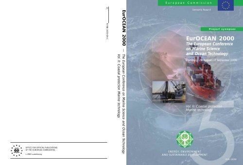
<strong>EurOCEAN</strong> <strong>2000</strong> — The European Conference on Marine Science and Ocean Technology<br />
Vol. II: Coastal protection Marine technology<br />
European Commission<br />
Community Research<br />
Vol. II: Coastal protection<br />
Marine technology<br />
ENERGY, ENVIRONMENT<br />
AND SUSTAINABLE DEVELOPMENT<br />
Project synopses<br />
<strong>EurOCEAN</strong> <strong>2000</strong><br />
The European Conference<br />
on Marine Science<br />
and Ocean Technology<br />
Hamburg, 29 August - 2 September <strong>2000</strong><br />
EUR 19359
Interested in European research?<br />
RTD info is our quarterly magazine keeping you in touch with main <strong>de</strong>velopments (results, programmes,<br />
events, etc). It is available in English, French and German. A free sample copy or free subscription<br />
can be obtained from:<br />
Directorate-General for Research, Communication Unit<br />
European Commission<br />
Rue <strong>de</strong> la Loi/Wetstraat 200, B-1049 Brussels<br />
Fax : (32-2) 29-58220<br />
E-Mail: research@cec.eu.int<br />
Internet: http://europa.eu.int/comm/research/<br />
EUROPEAN COMMISSION<br />
Research Directorate-General/D.I.3 - Energy, environment and sustainable <strong>de</strong>velopment<br />
Contact: Mr. Klaus - Günther BARTHEL - rue <strong>de</strong> la Loi, 200 (SDME 7/83), B-1049 Brussels<br />
Tel: (32-02 295 12 42) - Fax (32-02 296 30 24) E-mail: klaus-guenther.barthel@cec.eu.int
<strong>EurOCEAN</strong> <strong>2000</strong><br />
The European Conference<br />
on Marine Science<br />
and Ocean Technology<br />
Hamburg, 29 August - 2 September <strong>2000</strong><br />
Project Synopses<br />
Vol. II: Coastal protection - Marine technology
LEGAL NOTICE: Neither the European Commission nor any person acting on behalf of the Commission is responsible<br />
for the use which might be ma<strong>de</strong> of the following information.<br />
A great <strong>de</strong>al of additional information on the European Union is available on the Internet.<br />
It can be accessed through the Europa server (http://europa.eu.int).<br />
Cataloguing data can be found at the end of this publication.<br />
Luxembourg: Office for Official Publications of the European Communities, <strong>2000</strong><br />
ISBN 92-828-9714-1<br />
© European Communities, <strong>2000</strong><br />
Reproduction is authorised provi<strong>de</strong>d the source is acknowledged.<br />
Printed in Italy<br />
PRINTED ON WHITE CHLORINE-FREE PAPER
TABLE OF CONTENTS (Volumes I - II)<br />
Volume 1: Marine Processes, Ecosystems and Interactions..................................................1<br />
I.1 Marine systems research........................................................................................3<br />
I.1.1 Ciculation and exchange of water masses ............................................................3<br />
Variability of exchanges in the Northern seas (VEINS) ..............................................................5<br />
Tracing the water masses of the North Atlantic and<br />
the Mediterranean (TRACMASS) .............................................................................................10<br />
North Sea mo<strong>de</strong>l advection dispersion study 2: assessments<br />
of mo<strong>de</strong>l variability (NOMADS-II) ...........................................................................................16<br />
Comparative analysis and rationalisation of second moment<br />
turbulence mo<strong>de</strong>ls (CARTUM)..................................................................................................23<br />
I.1.2 Integrated ecosystem studies ...............................................................................29<br />
Cycling of Phosphorus in the Mediterranean (CYCLOPS) .......................................................31<br />
Role of microbial mats in bioremediation of hydrocarbon<br />
polluted coastal zones (MATBIOPOL)......................................................................................36<br />
The influence of UVR and climate conditions on fish stocks :<br />
A case study of the Northeast Artic cod (UVAC).....................................................................39<br />
Estimation of Primary Production for Fisheries Management<br />
(PROOF)...................................................................................................................................43<br />
Ocean margin exchange II - Phase II (OMEX II -PHASE II)....................................................49<br />
Ocean colour for the <strong>de</strong>termination of water column biological<br />
processes (BIOCOLOR) ............................................................................................................70<br />
Effect of nutrient ratios on harmful phytoplankton and<br />
their toxin production (NUTOX) ...............................................................................................76<br />
Molecular ecology of the Photosynthetic Procaryote Prochlorococcus,<br />
a key organism of oceanic ecosystems (PROMOLEC) .............................................................82<br />
Ecological effects of protection in Mediterranean marine reserves<br />
(ECOMARE) .............................................................................................................................91<br />
Processes of vertical exchange in shelf seas (PROVESS) .......................................................100<br />
The impact of appendicularia in European marine ecosystems (EURAPP).............................109<br />
III
Microbial assays for risk assessment (MARA)........................................................................112<br />
I.1.3 Marine biodiversity ............................................................................................119<br />
Monitoring Biodiversity of Pico-Phytoplankton in Marine Waters<br />
(PICODIV)...............................................................................................................................121<br />
Development and field validation of biosensor methods for the assessment<br />
of the effects of pollution and solar UV radiation on marine invertebrates.<br />
(UVTOX).................................................................................................................................128<br />
Biological control of harmful algal blooms in european coastal waters: role<br />
of eutrophication. (BIOHAB) ..................................................................................................135<br />
Microbial diversity in aquatic systems (MIDAS) ....................................................................139<br />
I.1.4 Marine biotechnology.........................................................................................145<br />
Lead potential of marine microorganisms from coastal, shelf and <strong>de</strong>ep sea<br />
sediments, a comparative assessment for optimized search strategies<br />
(MICROMAR).........................................................................................................................147<br />
Marine bacterial genes and isolates as sources for novel biotechnological<br />
Products (MARGENES) ..........................................................................................................153<br />
Biology of sponge natural products (SYMBIOSPONGE).......................................................159<br />
Marine cyanobacteria as a source for bioactive (apoptosis modifying)<br />
compounds with potential as cell biology reagents and drugs<br />
(Drugs from marine cyanobacteria) .........................................................................................164<br />
Methods to improve the supply of marine organisms for pharmaceutical<br />
related natural products chemistry (FAIRE) ............................................................................170<br />
I.1.5 Structure and dynamics of shelf ecosystems ....................................................173<br />
Influence of rising sea level on ecosystem dynamics of salt marshes (ISLED).......................175<br />
Atmospheric Nitrogen Inputs into the Coastal Ecosystem (ANICE) .......................................183<br />
Effects of climate induced temprerature change on marine coastal fishes<br />
(CLICOFI) ..............................................................................................................................190<br />
Submarine groundwater-fluxes and transport-processes from methane<br />
rich coastal sedimentary environments (SUB-GATE).............................................................197<br />
IV
Integrated nitrogen mo<strong>de</strong>l for european catchments (INCA)...................................................202<br />
Bridging effect assessment of mixtures to ecosystem situations and<br />
regulation (BEAM) ..................................................................................................................207<br />
Biogeochemical interactions between the Danube river and the<br />
Northwestern Black sea (EROS-21) ........................................................................................213<br />
Oceanographic application to eutrophication in regions of restricted exchange<br />
(OAERRE)...............................................................................................................................222<br />
Marine Effects of Atmospheric Deposition (MEAD) ..............................................................229<br />
Feed-backs of estuarine circulation and transport of sediments on phytobenthos<br />
(F-ECTS)..................................................................................................................................235<br />
Key coastal processes in the mesotrophic Skagerrak and the oligotrophic Northern<br />
Aegean: a comparative study (KEYCOP)................................................................................242<br />
Importance of organic matter from terrestrial sources for the production, community<br />
structure and toxicity of phytoplankton; role of micropredatos for transmission of<br />
toxins to commercial shellfish and fish larvae (DOMTOX) ....................................................251<br />
Effects of Eutrophicated seawater on rocky shore ecosystems studied in large littoral<br />
Mesocosms (EULIT)................................................................................................................258<br />
Long-term changes in Baltic Algal species and ecosystems (BIOBASE) ...............................267<br />
Statigraphical Development of the Glaciated European Margin (STRATAGEM)..................273<br />
I.1.6 Sedimentary processes .......................................................................................279<br />
Environmental Controls on Mound Formation along the European Margin<br />
(ECOMOUND)........................................................................................................................281<br />
The Mound Factory - Internal Controls (GEOMOUND).........................................................286<br />
Silicon cycling in the world ocean: the controls for opal preservation in the sediment<br />
as <strong>de</strong>rived from observations and mo<strong>de</strong>lling (SINOPS) ..........................................................293<br />
European marine sediment information network (EUMARSIN).............................................299<br />
I.2 Extreme ecosystems............................................................................................305<br />
Deep-sea Hydrothermal Vents: a Natural Pollution Laboratory (VENTOX) ..........................307<br />
Atlantic Coral Ecosystem Study (ACES).................................................................................310<br />
V
Sapropels and Palaeoceanography: palaeoceanographic, palaeoclimatic,<br />
palaeoenvironmental and diagenitic aspects of sapropel formation in the Eastern<br />
Mediterranean (SAP) ...............................................................................................................318<br />
Baltic Air-Sea-Ice study, a field experiment of Baltex (BALTEX-BASIS) ............................325<br />
I.3 Supporting initiatives.........................................................................................331<br />
European network for oceanographic data and information management<br />
(EURONODIM).......................................................................................................................333<br />
Mediterranean data archaeology and rescue of temperature, salinity and<br />
bio-chemical parameters (MEDAR) ........................................................................................341<br />
A searchable internet database of seabed samples from the ocean basins<br />
held at European institutions (EUROCORE)...........................................................................350<br />
Planning for a North West European Shelf Seas Ocean Data Assimilation<br />
and Forecast Experiment (ESODAE-Phase 1).........................................................................357<br />
Mediterranean mo<strong>de</strong>l networking and archiving program (MEDNET)...................................363<br />
National fleets of research vessels in Europe. Assessment of characteristics<br />
in comparison with future requirements (NATFLEET)...........................................................369<br />
Bergen Marine Food Chain research ingrastructure.................................................................372<br />
Volume 2 : Coastal Protection .............................................................................................379<br />
II.1.1 Coastal processes and morphodynamics ..............................................................381<br />
Surf and swash zone mechanics (SASME) ..............................................................................383<br />
Prediction of cohesive sediment transport and bed dynamics in estuaries<br />
and coastal zones with integrated numerical simulation mo<strong>de</strong>ls (COSINUS) .........................392<br />
Coastal study of 3-dimensional sand transport processes and morphodynamics<br />
(COAST3D).............................................................................................................................400<br />
Inlet dynamics initiative: Algarve (INDIA) .............................................................................407<br />
Sediment transport mo<strong>de</strong>lling in marine coastal environments (SEDMOC)...............................413<br />
VI
II.1.2 Mehtods for monitoring, forecasting and management of shelf seas<br />
and coastal zones ................................................................................................421<br />
Coastal region long-term measurements for colour remote sensing <strong>de</strong>velopment<br />
and validation (COLORS)........................................................................................................423<br />
Operational mo<strong>de</strong>lling for coastal zone management (OPCOM) ............................................430<br />
A European-wi<strong>de</strong> offshore/nearshore statistical toolbox for timely wave climate<br />
assessment (EUROWAVES) ...................................................................................................436<br />
European radar ocean sensing (EuroROSE) ............................................................................443<br />
Preparation and integration of analysis tools towards operational forecast of<br />
nutrients in estuaries of European rivers (PIONEER)..............................................................449<br />
Mediterranean forecasting system pilot project (MFSPP) ..........................................................457<br />
Assessment of antifouling agents in coastal environments (ACE)...........................................466<br />
Scour around coastal structures (SCARCOST)........................................................................474<br />
Validation of low level ice forces on coastal structures (LOLEIF)..........................................480<br />
The optimisation of crest level <strong>de</strong>sign of sloping coastal structures through<br />
prototype monitoring and mo<strong>de</strong>lling (OPTICREST)...............................................................487<br />
European shore platform erosion dynamics (ESPED) .............................................................495<br />
Volume 2 : Marine Technology.............................................................................................505<br />
III.1.1 Non-disturbing techniques.................................................................................507<br />
Automated i<strong>de</strong>ntification and characterization of marine microbial populations<br />
(AIMS).....................................................................................................................................509<br />
Sediment i<strong>de</strong>ntification for geotechnics by marine acoustics (SIGMA)..................................516<br />
Transmission of electromagnetic waves through sea water for imaging parameter<br />
measuring and communications (DEBYE) ..............................................................................524<br />
Improved microstructure measurement technologies for marine near surface flux<br />
studies (MITEC) ......................................................................................................................530<br />
Application of 3-dimensional electromagnetic induction by sources in the ocean<br />
(ISO-3D) ..................................................................................................................................540<br />
Automatic diatom i<strong>de</strong>ntification and classification (ADIAC)..................................................545<br />
VII
Subsea tools application research (STAR)...............................................................................552<br />
Dinoflagellate Categorisation by Artificial Neural Network (DiCANN).................................558<br />
III.1.2. Un<strong>de</strong>rwater communication and orientation...................................................565<br />
Longe range telemetry in ultra-shallow channels (LOTUS) ....................................................567<br />
Making seismic reflection profiles available to the wi<strong>de</strong>r scientific community<br />
(SEISCAN) ..............................................................................................................................575<br />
Shallow water acoustic communication network (SWAN)......................................................583<br />
Long range shallow water robust acoustic communication links (ROBLINKS) .....................588<br />
Un<strong>de</strong>rwater diving interpersonal communication and orientation system<br />
(UDICOS)...............................................................................................................................594<br />
Electroacoustic prototype for controlling the behaviour of marine mammals .........................600<br />
III.1.3 Un<strong>de</strong>rwater viewing ...........................................................................................605<br />
High resolution in-situ holographic recording and analysis of marine<br />
organisms and particles (HOLOMAR) ....................................................................................606<br />
III.1.4 Submarine geotechnics.......................................................................................615<br />
Grouted offshore piles for alternating loadings (GOPAL).......................................................617<br />
Very high resolution marine 3D seismic method for <strong>de</strong>tailed site<br />
investigation (VHR3D) ............................................................................................................624<br />
Advanced ROV package for automatic mobile inspection of sediments<br />
(ARAMIS) ...............................................................................................................................630<br />
A universersal docking-downloading-recharging system for AUVs<br />
(EURODOCKER)....................................................................................................................638<br />
Lightweight composite pressure housings for mid-water and Benthic applications<br />
(Composite Pressure Housings) ...............................................................................................645<br />
Advanced system integration for managing the coordinated operation<br />
of robotic ocean vehicles (ASIMOV) ......................................................................................649<br />
Geophysical and oceanographic station for abyssal research, 2nd phase:<br />
<strong>de</strong>ep sea scientific mission (GEOSTAR-2)..............................................................................658<br />
VIII
III.2.2 Oceanographic measurement and sampling equipment .................................667<br />
Hydrate autoclave coring equipment system (HYACE) ..........................................................669<br />
An autonomous system for monitoring air-sea fluxes using the inertial<br />
dissipation method and ship mounted instrumentation (AUTOFLUX) ...................................674<br />
Trace metals monitoring in surface marine waters and estuaries<br />
(Cd, Zn, Pb, Hg, Cu, Fe, Mn and Co) (MEMOSEA)...............................................................680<br />
Ocean tomography operational and utilization support (OCTOPUS)......................................687<br />
Spectroscopy using optical fibers in the marine environment (Sofie)......................................695<br />
Development and test of an innovative ion selective electro<strong>de</strong>s monitoring<br />
and control system for total nitrogen in marine waters .............................................................70<br />
IX
Volume II<br />
Coastal protection<br />
379
380
II.1.1. Coastal processes and morphodynamics<br />
381
382
TITLE: SURF AND SWASH ZONE MECHANICS :<br />
SASME<br />
CONTRACT NO: MAST3-CT97-0081<br />
COORDINATOR: Jørgen Fredsøe<br />
DHI Water and Environment<br />
Agern Allé 11<br />
DK-2970 Hørsholm, Denmark<br />
Tel: +45 45169200, Fax +45 45169292<br />
e-mail: jf@dhi.dk<br />
PARTNERS AND CONTACT PERSONS:<br />
Julio Zyserman<br />
DHI Water and Environment<br />
Agern Allé 11<br />
DK-2970 Hørsholm, Denmark<br />
Tel: +45 45169200, Fax +45 45169292<br />
jaz@dhi.dk<br />
Dano Roelvink<br />
Delft Hydraulics (DH)<br />
P.O. Box 177<br />
2600 MH Delft<br />
The Netherlands<br />
Tel: +31 15 285 8585, Fax: +31 15-285 8582<br />
Dano.Roelvink@wl<strong>de</strong>lft.nl<br />
Hans Dette<br />
Leichtweiss Institut für Wasserbau (LWI)<br />
Institut für Hydromechanik und<br />
Küsteningenieurwesen<br />
P.O.B. 3329<br />
Beethovenstrasse 51A<br />
D-38106 Braunschweig<br />
Germany<br />
Tel: +49 531-391-3930, Fax: +49 531-391-821<br />
H.Dette@tu-bs.<strong>de</strong><br />
Jesper Damgaard<br />
HR Wallingfor (HR)<br />
Coastal Group<br />
Howbery Park<br />
Wallingford, OXON OX10 8BA, UK<br />
Tel: +44 1491-835381,<br />
Fax: +44 1491-832233<br />
jsd@hrwallingford.co.uk<br />
Denis Aelbrecht<br />
Laboratoire National d´Hydraulique (LNH)<br />
EDF-LNH<br />
6. Quai Watier B.P. 49<br />
78401 Chatou Ce<strong>de</strong>x<br />
France<br />
Tel: +33 130-877412, Fax: +33 130-878086<br />
Denis.Aelbrecht@edfgdf.fr<br />
Rolf Deigaard<br />
Technical University of Denmark (DTU)<br />
Department of Hydrodynamics and Water<br />
Resources (ISVA), Building 115<br />
DK-2800 Lyngby, Denmark<br />
Tel: +45 45251422, Fax: +45 45936328<br />
rd@isva.dtu.dk<br />
383
Jan van <strong>de</strong> Graaff<br />
Delft University of Technology (DUT)<br />
Dept. of Civil Engineering<br />
Hydraulic and Offshore Engrg. Division<br />
P.O. Box 5048<br />
Stevinweg 1<br />
2628 CN Delft<br />
The Netherlands<br />
Tel: +31 15-278 4846, Fax: +31 15-278 5124<br />
J.van<strong>de</strong>Graaff@ct.tu<strong>de</strong>lft.nl<br />
D. Howell Peregrine<br />
University of Bristol (BrU)<br />
School of Mathematics<br />
University Walk<br />
Bristol BS8 1TW, England<br />
Tel: +44 117-928 7971, Fax: +44 117-928 7999<br />
D.H.Peregrine@bristol.ac.uk<br />
Paul A.D. Bird<br />
University of Plymouth (UPl)<br />
Faculty of Technology<br />
School of Civil and Structural Engineering<br />
Palace Court, Palace Street<br />
Plymouth<br />
Devon PL1 2DE, UK<br />
Tel: +44 1752-232534, Fax: +44 1752 232627<br />
pbird@plymouth.ac.uk<br />
Inigo J. Losada<br />
Universidad <strong>de</strong> Cantabria (UCa)<br />
Ocean & Coastal Research Group<br />
E.T.S.I. <strong>de</strong> Caminos, Canales y Puertos<br />
Av. <strong>de</strong> los Castros s/n<br />
39005 Santan<strong>de</strong>r, Spain<br />
Tel: +34 942-201810, Fax: +34 942-201860<br />
inigo@puer.unican.es<br />
384<br />
Albert Falques<br />
Universitat Politecnica <strong>de</strong> Catalunya<br />
(UPC)Dept. Fisica Aplicada<br />
Modul B5, Campus Nord UPCE-08034<br />
Barcelona, Spain<br />
Tel: +34 93 401 1831, Fax: +34 93 401 6090<br />
falques@fa.upc.es<br />
Marco Petti<br />
University of Udine (UUD)<br />
Dipartimento di Georisorse e TerritorioVia<br />
<strong>de</strong>l Contonificio, 114 33100 Udine, Italy<br />
Tel: +39 0432 558712,<br />
Fax: +39 0432 558700<br />
marco.petti@uniud.it<br />
Clive Greated<br />
The University of Edinburgh (UEDIN)<br />
Fluid Dynamics Unit<br />
Dept. of Physics and Astronomy<br />
Kings Building, Mayfield Road<br />
Edinburgh EH9 3JZ, UK<br />
Tel: +44 131-650-5232,<br />
Fax: +44 131-650-5220<br />
C.A.Greated@ed.ac.uk
SURF AND SWASH ZONE MECHANICS (SASME)<br />
J. FREDSØE<br />
DHI Water and Environment<br />
Agern Allé 11<br />
DK-2970 Hørsholm, Denmark<br />
B. MUTLU SUMER<br />
Technical University of<br />
Denmark (DTU)<br />
Department of Hydrodynamics<br />
and Water Resources (ISVA),<br />
Building 115<br />
DK-2800 Lyngby, Denmark<br />
JESPER DAMGAARD<br />
HR Wallingfor<br />
Coastal Group<br />
Howbery Park<br />
Wallingford, OXON OX10<br />
8BA, UK<br />
ROLF DEIGAARD<br />
Technical University of<br />
Denmark (DTU)<br />
Department of Hydrodynamics<br />
and Water Resources (ISVA),<br />
Building 115<br />
DK-2800 Lyngby, Denmark<br />
SUMMARY<br />
This MAST project started on 1 October 1997, and runs for 3 years. The<br />
total costs is estimated to be 2.895.000 ECU of which the EU contribution<br />
will be 1.810.000 ECU. The main aims of the project are <strong>de</strong>scribed, and<br />
the work plan is summarized. No results are yet available from the project.<br />
1. INTRODUCTION<br />
DANO ROELVINK<br />
Delft Hydraulics<br />
P.O. Box 177<br />
2600 MH Delft<br />
The Netherlands<br />
The objective of the present project is to investigate the physical processes which take place in<br />
the surf zone on a coast with and without coastal structures.<br />
The project shall lead to a significantly improved <strong>de</strong>scription of the cross-shore and longshore<br />
sediment transport, which mainly occurs within the surf zone.<br />
The SASME project is divi<strong>de</strong>d into two interlinked parts:<br />
I. Surf and swash zone hydrodynamics and sediment transport, and<br />
II. Surf and swash zone morphology.<br />
The surf and swash zone hydrodynamics and sediment transport will concentrate on the<br />
behaviour of breaking and broken waves, their generation of small and large scale turbulence,<br />
and the resulting sediment transport.<br />
The morphological study focus on the bed behaviour in the surf/swash zone which inclu<strong>de</strong>s<br />
bed-instabilities; formation of bars and their behaviour (like erosion and accretion in 2<br />
horizontal dimensions; non-uniformities in the alongshore direction due to rip currents).<br />
The far field impact of coastal structures is investigated: the effect of the modifications of<br />
wave, current and sediment transport fields by the structures. The project thus address<br />
important aspects of the function of the coastal structures. The project does not treat the three-<br />
385
dimensional near-field hydrodynamics and sediment transport around structures that are<br />
associated with local scour phenomena.<br />
In terms of practical outcome, the project is expected to produce significant improvements in<br />
“medium” term mo<strong>de</strong>lling, which is necessary for the <strong>de</strong>velopment of longer term prediction<br />
methods. In addition, improvements at a fundamental level will yield a basis for <strong>de</strong>velop-ments<br />
of transport and mixing mo<strong>de</strong>ls for quantities other than sediments in the surf and swash zones,<br />
plus some results of wi<strong>de</strong>r significance, for example in relation to breaking waves in <strong>de</strong>ep<br />
water and their significance for air-sea exchange and mixing.<br />
2. DESCRIPTION OF THE INDIVIDUAL PROJECTS<br />
SASME is divi<strong>de</strong>d into the following four main projects which each has a project lea<strong>de</strong>r and an<br />
assistant project lea<strong>de</strong>r. The 4 projects are:<br />
• Project 1. Breaking/broken waves in surf/swash zone. Project lea<strong>de</strong>r: Rolf Deigaard, DTU.<br />
• Project 2. Vertical structure of motion and associated sediment transport plus<br />
morphological mo<strong>de</strong>lling of coastal profiles. Project lea<strong>de</strong>r: B. Mutlu Sumer, DTU.<br />
• Project 3. Horizontal structure of wave- and breaker-induced motion and area-mo<strong>de</strong>lling.<br />
Project lea<strong>de</strong>r: Jesper Damgaard, HR.<br />
• Project 4. Structure-seabed interaction. Project lea<strong>de</strong>r: Dano Roelvink, DH.<br />
Project 1: Breaking and broken waves in the surf and swash zone<br />
Participants In the project: UPl, BrU, HR, DH, UUd, LWI, UCa, DHI, DTU.<br />
This project <strong>de</strong>al with waves just before they break, the processes of wave breaking and the<br />
further propagation as broken waves to the limits of the run-up in the swash zone. The study<br />
treats plane as well as barred coasts and aspects of hydrodynamics and sediment transport. The<br />
research has inclu<strong>de</strong>d analysis of field data, analysis of physical processes, mathematical<br />
mo<strong>de</strong>lling and laboratory experiments.<br />
Breaking and broken waves have been analysed from field data that have been ma<strong>de</strong> available<br />
for the project. The data are from locations in Germany: at the Baltic coast and at the North Sea<br />
coast (Sylt). The measurements have been specifically aimed at improving the physical<br />
un<strong>de</strong>rstanding of breaking processes, energy dissipation and the transformation of wave energy<br />
across the coastal profile. Field work has been carried out in Spain to study infra gravity waves<br />
especially in pocket beaches.<br />
The laboratory experiments inclu<strong>de</strong> a study of accelerated flow in porous media at high<br />
Reynolds numbers. Flume experiments have been carried out on breaking waves over<br />
permeable and impermeable beds. Extensive experiments have been carried out on swash zone<br />
conditions for different breaker types and beach slopes. The measurements inclu<strong>de</strong> among<br />
others surface elevations, run-up, the mean motion, turbulence intensity and the structure of the<br />
turbulence (length scales). The role of long waves for the dynamics of a surf zone has been<br />
investigated including the generation of long waves by a moving breakpoint. The interaction<br />
between breakpoint-generated and bound long waves has been investigated. Data has been<br />
386
available for plane and barred beaches. A theoretical study has been ma<strong>de</strong> on the generation of<br />
long waves from wave groups and the non-linear effect of long waves on short waves.<br />
The effects of wave reflection on surf zone dynamics have been studied by experimental and<br />
theoretical investigations.<br />
Boussinesq wave mo<strong>de</strong>ls for surf zone conditions have been verified against published data,<br />
including wave generated currents. Efficient 2DH mo<strong>de</strong>ls <strong>de</strong>scribing the vorticity generated by<br />
bores have been <strong>de</strong>veloped.<br />
Sediment transport in surf beat and long waves has been studied by numerical mo<strong>de</strong>ls verified<br />
against published data, and by analysis of hydrodynamic data from flume experiments to<br />
<strong>de</strong>termine zones of convergence and divergence. The theoretical study inclu<strong>de</strong>s the effect of<br />
bound long waves outsi<strong>de</strong> the breaker zone, surf zone wave mo<strong>de</strong>ls that resolve the low<br />
frequency motion but averages out the short waves, and by phase resolving wave mo<strong>de</strong>ls.<br />
The propagation of edge waves has been mo<strong>de</strong>lled for a plane beach with a shelf and a seawall<br />
to explain the formation of rhythmic morphology at a location in Spain. Work has continued<br />
with mo<strong>de</strong>lling of edge waves along a permeable barrier and resonance of a harbour un<strong>de</strong>r<br />
edge wave forcing.<br />
Project 2: Vertical structure of motion and associated sediment transport,<br />
and morphological mo<strong>de</strong>lling of coastal profiles<br />
The goal of the project is to study 3-D structures of wave-generated motions in the surf zone<br />
with focus on the large-scale vortices generated by plunging breakers, the turbulence<br />
generated by breaking and broken waves and the velocity distribution in wave-driven currents,<br />
and also to investigate morphological mo<strong>de</strong>lling of coastal profiles. Project 2 consists of two<br />
topics: (1) Vertical structure of wave- and breaker-induced motion and the associated sediment<br />
transport (Topics 1.2a - d); and (2) morphological mo<strong>de</strong>lling of the surf zone without structures<br />
(Topic 2.1a).<br />
Topic 1.2a. Description of a plunging breaker. The work has been concentrated on two<br />
aspects: (1) DHI/ISVA has been <strong>de</strong>veloping a mo<strong>de</strong>l for plunging breakers and to study the<br />
turbulent flow structures initiated by plunging breakers. (2) UEDIN in cooperation with ISVA<br />
has been doing PIV experiments of plunging breakers. The Volume of Fluid (VOF) method has<br />
been implemented in the general non-orthogonal Navier-Stokes solver in the DHI/ISVA work.<br />
Mo<strong>de</strong>l results have been compared to PIV measurements performed by UEDIN un<strong>de</strong>r waves<br />
breaking on a 1:13.5 slope. The k- mo<strong>de</strong>l has been used to mo<strong>de</strong>l the turbulence, and applied<br />
to simulate periodic breaking waves. All PIV experiments have been completed at two<br />
laboratories, at UEDIN and at ISVA. Different dynamics of selected breaker types have been<br />
found. The comparison of the mo<strong>de</strong>l results to measurements will be completed by the end of<br />
the project period.<br />
Topic 1.2b. Wave- boundary-layer investigation un<strong>de</strong>r breaking waves. An experimental<br />
study (ISVA) is being un<strong>de</strong>rtaken to study the interaction between turbulence generated by<br />
wave breaking, and the turbulence generated in an oscillatory boundary layer. The experiments<br />
are carried out in an oscillating water tunnel, and the wave-breaking generated turbulence is<br />
simulated by placing a grid in the upper part of the tunnel. The externally generated turbulence<br />
affects the transition to turbulence in the bed boundary layer, the phase difference between the<br />
free stream velocity and the bed shear stress and the wave friction factor. In another study at<br />
387
ISVA, turbulence un<strong>de</strong>r spilling breakers and broken waves has been investigated by wave<br />
flume experiments.<br />
Topic 1.2c. Influence of breaking waves on sediment transport. The work un<strong>de</strong>rtaken by<br />
DHI/ISVA un<strong>de</strong>r Topic 1.2a (see above), constitutes a key element for this research. The<br />
sediment transport has been inclu<strong>de</strong>d in an advanced Navier-Stokes solver in two-dimensions.<br />
DHI/ISVA will continue the <strong>de</strong>velopment of the free-surface method for breaking and broken<br />
waves. Also, comparison of the sediment transport rates to experimental results, and<br />
sensitivity analysis of for instance the fall velocity, will be ma<strong>de</strong>.<br />
Topic 1.2d. Wave-induced currents. The objective is to <strong>de</strong>velop a 3-D wave-driven current<br />
mo<strong>de</strong>l. A start has been ma<strong>de</strong> in testing the 3D implementation against 2D (laboratory) cases.<br />
Furthermore the present implementation has been combined with a research version which has<br />
on-line sediment transport module inclu<strong>de</strong>d. The wave effects are implemented in a co<strong>de</strong> that<br />
will also be used for morphological mo<strong>de</strong>lling of complex bathymetries. Testing of 3D<br />
implementation against 3D cases will be sought. The first comparisons have shown that<br />
especially the streaming effects are not yet inclu<strong>de</strong>d correctly. Research will focus on this<br />
aspect for the rest of the project period.<br />
Topic 2.1a. Morphological mo<strong>de</strong>lling of the surf zone without structures. Two research<br />
groups have been working on this topic, namely DHI and DH. The work DHI un<strong>de</strong>rtakes<br />
basically <strong>de</strong>als with vertical structure of motion and associated sediment transport plus<br />
morphological mo<strong>de</strong>lling of coastal profiles. A mathematical mo<strong>de</strong>l has been <strong>de</strong>veloped that<br />
<strong>de</strong>scribes the 3D distribution of the mean shear<br />
stress, the time varying eddy viscosity, velocity profiles, suspen<strong>de</strong>d sediment concentrations<br />
and sediment transport. The sediment transport mo<strong>de</strong>l has been exten<strong>de</strong>d to inclu<strong>de</strong> irregular<br />
wave trains. A phase resolving mo<strong>de</strong>l has been <strong>de</strong>veloped to simulate the morphological<br />
evolution of a cross-shore beach profile. The <strong>de</strong>pth averaged-hydrodynamics are calculated<br />
from a wave mo<strong>de</strong>l based on the Boussinesq equations. The Quasi 3D sediment transport<br />
mo<strong>de</strong>l has been incorporated into a phase averaged morphological mo<strong>de</strong>l for cross-shore<br />
profile evolution. The morphological mo<strong>de</strong>l has been used to investigate the morphological<br />
<strong>de</strong>velopment of beach profiles un<strong>de</strong>r the attack of obliquely inci<strong>de</strong>nt waves. Regarding the DH<br />
study un<strong>de</strong>r this topic, the objective is to mo<strong>de</strong>l the erosion/accretion of dry beaches in a<br />
morphodynamic area mo<strong>de</strong>l.The principle i<strong>de</strong>a is to extrapolate sediment transport from the<br />
last wet point to the highest dry point of a grid row or column, where transport is assumed to be<br />
a linear function of the height; in this way, profiles can uniformly shift in horizontal direction.<br />
A 1-D version of this approach has been successfully tested. Subsequently, a 2-D<br />
implementation has been carried out which has been tested successfully on the Keta Lagoon<br />
case.<br />
Project 3. Horizontal structure of wave- and breaker-induced motion and<br />
area mo<strong>de</strong>lling.<br />
Goal of the project: to investigate the hydrodynamics, sediment transport and morphodynamics<br />
in the surf and swash zone, with focus on the 2DH (two dimensions in the horizontal) view<br />
point. Most important results until now are as follows<br />
• for a realistic longshore current, in presence of eddy viscosity, resonant triads, which can<br />
involve unstable and/or stable mo<strong>de</strong>s, can exist and a resonant triad, comprising 3 linearly<br />
stable mo<strong>de</strong>s <strong>de</strong>rived from a linear stability analysis, can exhibit explosive instabilities.<br />
388
• the nearshore circulation mo<strong>de</strong>l SHORECIRC has been applied to study the infragravity<br />
wave response to the bathymetry and shortwave forcing. Specific attention has been paid<br />
to the generation of accurate boundary conditions for the bound incoming long wave.<br />
• a linear mo<strong>de</strong>l has been <strong>de</strong>veloped for the generation of long waves by obliquely inci<strong>de</strong>nt<br />
grouped short waves on an along-shore uniform beach. Effects of set-up and longshore<br />
currents on the long wave response are taken into account.<br />
• the <strong>de</strong>velopment of rip channels has been simulated with a 2DH numerical coastal area<br />
mo<strong>de</strong>l. The results for normal inci<strong>de</strong>nce exhibit significant scatter but compare relatively<br />
well with analytical results.<br />
• experiments have been carried out on the circulation current over a longshore bar with a<br />
rip channel. The relation bewtween the water level, the wave conditions and the maximum<br />
velocity in the rip current has been investigated.<br />
• the horizontal exchange of momentum in wave-driven currents and its importance for the<br />
velocity distribution has been invstigated. It is found that wave-current interaction can<br />
play an important role.<br />
• survey data from the test site Rantum, Sylt, North Sea has been finalised, behavioural<br />
trends of morphologic changes, rip currents and current systems have been <strong>de</strong>ducted.<br />
• a simplified linear mo<strong>de</strong>l for examining bar stability has now been <strong>de</strong>veloped. Results<br />
clearly indicate that a barred beach is less stable and will tend to exhibit instability.<br />
• a stability analysis and the investigation into the initial formation of rip channels on a<br />
long, straight and uniform longshore bar has been performed with a numerical mo<strong>de</strong>lling<br />
system.<br />
• the Coast3D test site of Egmond has been mo<strong>de</strong>lled using a 3D numerical mo<strong>de</strong>lling<br />
system.<br />
• a systematic exploration of the linear instability with simple <strong>de</strong>scriptions of sediment<br />
transport in case of oblique inci<strong>de</strong>nce has been achieved. Two behaviors are obtained<br />
<strong>de</strong>pending of the<br />
Project 4. Structure-seabed interaction<br />
Goal of this project: This project aims at un<strong>de</strong>rstanding, mo<strong>de</strong>lling and <strong>de</strong>scribing the effects of<br />
various coastal structures on the nearshore morphology. The project is divi<strong>de</strong>d into two topics:<br />
• mo<strong>de</strong>lling of the far field morphological evolution around structures, and<br />
• review of the experience on implementation of coastal structures.<br />
The mo<strong>de</strong>lling applied to the role of structures will profit by <strong>de</strong>velopments and improvements<br />
carried out in other parts of SASME. The capabilities and limitations of the different mo<strong>de</strong>lling<br />
principles for different types of structures are analysed. The mo<strong>de</strong>l results are used to analyse<br />
the flow, transport pattern and morphological <strong>de</strong>velopment around the structures, to obtain a<br />
better un<strong>de</strong>rstanding of the effect of the structures and of how a series of structures interacts.<br />
The aim of the review study is to provi<strong>de</strong> clear gui<strong>de</strong>lines on the use of coastal structure in<br />
coastline protection programmes. These gui<strong>de</strong>lines will be based on a review of existing<br />
experience with structures, and on the results of the <strong>de</strong>tailed mo<strong>de</strong>lling of the effects of<br />
structures during the SASME project. The gui<strong>de</strong>lines are recognised as one of the most<br />
important end products of SASME and will be published both in a <strong>de</strong>tailed report and as a<br />
review paper.<br />
389
Most important results until now:<br />
WL | <strong>de</strong>lft hydraulics (DH) has focused on the <strong>de</strong>scription of turbulence effects and 3D<br />
structure of<br />
transport and resulting morphological changes around harbours and long breakwaters (lit [1]).<br />
It is also investigating the effect of beach nourishments. It will also do some <strong>de</strong>pth-averaged<br />
runs for situations with groins for comparison with LNH's 3D approach<br />
Danish Hydraulic Institute (DHI) looks at the morphological evolution around emerged and<br />
submerged offshore breakwaters with 2DH and quasi3D approaches (lit [2]), and investigates<br />
the effects of diffraction and directional spreading.<br />
Laboratoire Nationale d' Hydraulique (LNH) investigates the effects of groins using a 3D<br />
approach (lit [3]).<br />
Delft University of Technology (DUT) has looked into the effects of submerged breakwaters<br />
and is now investigating the equilibrium shape of natural bays and bays formed between<br />
offshore breakwaters, using a 2DH approach (lit [4]).<br />
390
Together the partners span most types of structures. In a collaboration between all partners, the<br />
processes around these structures and the state of the art (including present improvements) of<br />
mo<strong>de</strong>lling these processes will be <strong>de</strong>scribed in a review paper. A review paper on the practical<br />
use of structures and morphological <strong>de</strong>sign consi<strong>de</strong>rations is being prepared.<br />
_____________<br />
SASME homepage with a lot of additional information: www.wl<strong>de</strong>lft.nl/sasme/sasme.htm<br />
391
TITLE : PREDICTION OF COHESIVE SEDIMENT<br />
TRANSPORT AND BED DYNAMICS IN<br />
ESTUARIES AND COASTAL ZONES WITH<br />
INTEGRATED NUMERICAL SIMULATION<br />
MODELS: COSINUS<br />
CONTRACT N° : MAS3 CT97-0082<br />
COORDINATOR : Prof. Jean E. Berlamont<br />
Hydraulics Laboratory, Katholieke Universiteit Leuven,<br />
<strong>de</strong> Croylaan 2, B 3001 Leuven, Belgium.<br />
Tel: +32 16 321660<br />
Fax: +32 16 321989<br />
E-mail: jean.berlamont@bwk.kuleuven.ac.be<br />
PARTNERS :<br />
Dr Ole Petersen Dr Damien Violeau<br />
Danish Hydraulic Institute Electricité <strong>de</strong> France<br />
DHI Water and Environment Laboratoire National d’Hydraulique et <strong>de</strong><br />
L’Environnement (LNHE)<br />
Agern Allé 11 Quai Wattier 6<br />
DK-2970 Horsholm, Denmark F – 78401 Chatou, France<br />
Tel. : +45-45-169200 Tel. : +33-1-30-877255<br />
Fax : +45-45-169292 Fax : +33-1-30-878086<br />
E-mail : Osp@dhi.dk E-mail : damien.violeau@edf.fr<br />
Prof. Mark Markofsky Dr Johan C. Winterwerp<br />
Universität Hannover (UHA) Technische Universiteit Delft (TUD)<br />
Institut für Strömungsmechanik Dept. of civil engineering<br />
Appelstrasse 9a Stevinweg 1<br />
D-30169 Hannover, Deutschland NL-2628 CN Delft, Ne<strong>de</strong>rland<br />
Tel. : +49-511-762.3776 Tel. : +31-15-2781971<br />
Fax : +49-511-762.3777 Fax : +31-15-2785975<br />
E-mail : mark@hydromech.uni-hannover.<strong>de</strong> E-mail : h.winterwerp@ct.tu<strong>de</strong>lft.nl<br />
Prof. Keith Dyer Dr Hervé Michallet<br />
University of Plymouth (UPL) Université Joseph Fourrier, Grenoble (UJF)<br />
Institute of Marine Studies Laboratoire <strong>de</strong>s Ecoulements Geophysiques &<br />
Drake Circus Industriels (LEGI)<br />
Plymouth PL4 8AA, UK BP 53<br />
F-38041 Grenoble Cé<strong>de</strong>x 9, France<br />
Tel. : +44-1752-232420 Tel.: +33-476825060<br />
Fax : +44-1752-232406 Fax : +33-476825001<br />
E-mail : K.Dyer@plymouth.ac.uk E-mail: michalle@hmg.inpg.fr<br />
392
Dr Johan C. Winterwerp Dr Gilliane Sills<br />
Delft Hydraulics (DH) University of Oxford (UOX)<br />
P.O. Box 177 Department of Engineering Science<br />
Nl-2600 MH Delft, Ne<strong>de</strong>rland Parks Road<br />
Tel. : +31-15-2858813 Oxford OX1 3PJ, UK<br />
Fax : +31-15-2858710 Tel. : +44-1865-273164<br />
E-mail : han.winterwerp@wl<strong>de</strong>lft.nl Fax : +44-1865-273907<br />
E-mail : Gilliane.Sills@eng.ox.ac.uk<br />
.<br />
Dr Bill Roberts<br />
H.R. Wallingford,<br />
Howbery Park<br />
Wallingford 0X10 8BA, U.K.<br />
Tel.: +44-1491-835381<br />
Fax: +44-1491-832233<br />
Email: wr@hrwallingford.co.uk<br />
393
394<br />
PREDICTION OF COHESIVE SEDIMENT TRANSPORT AND BED<br />
DYNAMICS IN ESTUARIES AND COASTAL ZONES WITH<br />
INTEGRATED NUMERICAL SIMULATION MODELS<br />
Jean Berlamont 1 , Erik Toorman 1 , Keith Dyer 2 , Han Winterwerp 3 , Bill Roberts 4 , Damien<br />
Violeau 5 ,<br />
Mark Markofsky 6<br />
1 Katholieke Universiteit Leuven, Belgium; 2 University of Plymouth, U.K.;<br />
3 Delft Hydraulics and TUDelft, the Netherlands; 4 HR. Wallingford, U.K; 5 Electricité <strong>de</strong><br />
France, LNHE, France; 6 Universität Hannover, Germany<br />
INTRODUCTION<br />
The management of coastal zones and estuaries requires accurate and <strong>de</strong>tailed knowledge to<br />
cope with their problems such as wetland protection and restoration, maintenance of navigation<br />
channels, dredging and dredged material relocation, effects of construction works on siltation<br />
and turbidity levels, pollutant transport, etc. Development and application of this knowledge<br />
requires <strong>de</strong>tailed mathematical mo<strong>de</strong>ls, amongst which full three-dimensional co<strong>de</strong>s. This is<br />
becoming practically feasible in view of the current <strong>de</strong>velopments in soft- and hardware. The<br />
physical un<strong>de</strong>rstanding and mathematical <strong>de</strong>scription or “mo<strong>de</strong>lling” of the processes however<br />
is still lagging behind, especially with respect to the presence of concentrated benthic (nearbed)<br />
suspension layers (CBS).<br />
PROJECT METHODOLOGY<br />
The state of the art knowledge on cohesive sediment transport shows that there is still a lack of<br />
experimental data on the role of flocculation and turbulence in the formation and erosion of<br />
mud beds and on the formation of CBS (concentrated benthic suspensions, or “fluid mud”).<br />
Therefore, an experimental programme has been set up to obtain these data. It consisted of<br />
field measurements in the Tamar estuary on floc formation and laboratory experiments on<br />
formation and erosion of mud beds and CBS, and the influence of floc structure and turbulence<br />
on these processes.<br />
The data of the experimental programme, together with other relevant data from literature have<br />
been stored in a database, which at the end of the project will be accessible to the public.<br />
Process modules have been <strong>de</strong>veloped and implemented into <strong>de</strong>tailed 1D and 2D vertical<br />
mo<strong>de</strong>ls which solve the full hydrodynamic, turbulent energy and sediment mass conservation<br />
equations. Two different bed mo<strong>de</strong>ls, to be coupled to these hydrodynamic mo<strong>de</strong>ls have been<br />
<strong>de</strong>veloped as well (1DV point mo<strong>de</strong>l). The data from the database have been used to calibrate<br />
and validate the process modules.<br />
The process modules have been parameterised to obtain relatively simple formulations, which<br />
can be implemented into currently used 3D and 2DH engineering system mo<strong>de</strong>ls.<br />
The performance of the improved system mo<strong>de</strong>ls has been tested by application of the mo<strong>de</strong>ls<br />
to a schematic estuary, for which a 2DV solution with the <strong>de</strong>tailed research mo<strong>de</strong>l is used as a<br />
reference. Various scenarios have been simulated. The mo<strong>de</strong>ls have also been applied to three
eal estuaries ( Tamar, Loire and Weser). Data to set-up and calibrate the mo<strong>de</strong>l applications<br />
are stored in the database. From the experience with the large-scale applications feed back has<br />
been produced towards the process module <strong>de</strong>velopment and their parameterisations.<br />
RESULTS<br />
Sediment - turbulence interaction<br />
For the numerical mo<strong>de</strong>lling of sediment - turbulence interaction, the most commonly used<br />
engineering turbulence mo<strong>de</strong>ls have been used, i.e. the Prandtl mixing length (PML) and the kε<br />
mo<strong>de</strong>l.<br />
Suspen<strong>de</strong>d sediment particles cause damping of turbulent energy in the flow. Traditionally, this<br />
effect is parameterised by the use of semi-empirical damping functions, which are applied to<br />
correct the turbulent eddy viscosity (in the PML mo<strong>de</strong>l) and the sediment mixing coefficient<br />
(or eddy diffusivity) for neutral conditions. The k-ε mo<strong>de</strong>l inclu<strong>de</strong>s the buoyancy effect<br />
explicitly but still needs the damping functions in the bed boundary conditions and the<br />
buoyancy term. Data on turbulence damping in stratified flows from the literature have been<br />
reanalysed, together with numerical data generated with the k-ε mo<strong>de</strong>l. Based on these results<br />
and on theoretical consi<strong>de</strong>rations, new damping functions have been proposed and tested.<br />
High <strong>de</strong>nsity gradients at the bed result in an apparent reduction of the bottom roughness with<br />
consequently higher transport and erosion rates than expected when the mo<strong>de</strong>l would not<br />
account for these buoyancy effects in the bed boundary conditions. A new bottom boundary<br />
treatment method has been proposed, which yields the correct bed shear stress.<br />
When a flowing suspension <strong>de</strong>celerates during a tidal cycle, hin<strong>de</strong>red settling may lead to the<br />
formation of a two-layer stratified flow with a distinct <strong>de</strong>nsity interface, the lutocline.<br />
Turbulence can be completely suppressed at this interface, as a result of which no sediment can<br />
be suspen<strong>de</strong>d in the upper layer, increasing the amount of sediment in the lower layer further.<br />
Hence a snow-ball effect occurs resulting in a collapse of the turbulence field and the vertical<br />
concentration profile. Un<strong>de</strong>r certain conditions this interface becomes unstable, resulting in<br />
internal waves which generate new turbulence and mixing across the lutocline. It has been<br />
proposed to mo<strong>de</strong>l this turbulence generation in a parameterised form as an additional eddy<br />
viscosity. An experimental and theoretical study was carried out to establish the effects of nonlocally<br />
produced turbulence on the mixing<br />
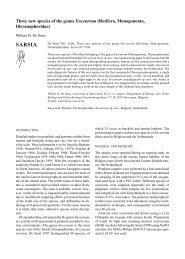
Ratio of the mixing to the momentum damping function (or normalised inverse<br />
Schmidt number) as a function of the gradient Richardson number (symbols =<br />
various data from the literature, fine line = Munk & An<strong>de</strong>rson (1948), dashed<br />
line = Ellison (1956), dotted line = Kranenburg (1999), thick line = new<br />
proposal)<br />
Fs/Fm<br />
1<br />
0.8<br />
0.6<br />
0.4<br />
0.2<br />
0<br />
0.001 0.01 0.1 1 10 100<br />
Ri<br />
395
processes of CBS. This is particularly relevant in case of spatially confined occurrences of<br />
CBS/fluid mud, as often encountered in nature.<br />
Flocculation<br />
Because, as far as cohesive suspensions are concerned, laboratory experiments cannot scale the<br />
turbulent properties of natural flows a<strong>de</strong>quately, field measurements were obtained of floc<br />
characteristics. The measurements were taken in September 1998 in the upper reaches of the<br />
Tamar Estuary, and covered the neap and spring ti<strong>de</strong> conditions. In that location the turbidity<br />
maximum is well <strong>de</strong>veloped and suspension concentrations of or<strong>de</strong>r g/l are present. The aim of<br />
the experiment was to measure floc size and settling velocity and their <strong>de</strong>pen<strong>de</strong>nce on salinity,<br />
concentration and turbulent shear.<br />
Two stations about 1km apart in the centre of the channel were <strong>de</strong>ployed simultaneously. At<br />
both stations frequent profiles of velocity, salinity, temperature, and suspen<strong>de</strong>d sediment<br />
concentration were obtained, and Owen tube measurements of settling velocity were taken. At<br />
the lower station profiles of floc size were taken with a Lasentec P-100 system (Law et al.,<br />
1997), and near bed measurements of floc size, settling velocity, and effective <strong>de</strong>nsity obtained<br />
with the INSSEV instrument (Fennessy et al., 1994). Also turbulence parameters were<br />
measured with miniature electromagnetic flowmeters above and below the INSSEV. At the<br />
upper station a LISST laser diffraction particle sizer was <strong>de</strong>ployed, vi<strong>de</strong>o measurement of floc<br />
size and settling velocities were observed within Owen tube samples. Additionally, samples<br />
were taken for laboratory analysis of the carbohydrate and chlorophyll a contents and CHN<br />
ratios.<br />
Suspen<strong>de</strong>d near bed sediment concentrations ranged from 16 mg/l on a neap ti<strong>de</strong> to 7 g/l on a<br />
spring ti<strong>de</strong>. Maximum velocities were 0.5 and 1.5 m/s, respectively. Typical spring ti<strong>de</strong> shear<br />
stresses were 0.68 N/m 2 at the level of the INSSEV. The number of flocs per INSSEV sample<br />
varied between 14 and 1150. Floc sizes up to 600 microns were observed. Examination of the<br />
settling velocity spectra of the flocs has indicated that the settling velocity Ws can be<br />
represented in simple linear correlation by: Ws = 5.784 (Shear) 0.606 and Ws = 0.524 (SPM) 0.249 ,<br />
where Ws is in mm/s, shear is in N/m 2 and SPM in mg/l. Also the ratio of macroflocs to<br />
396<br />
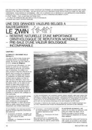
Settling velocity (Ws) mm/sec<br />
10<br />
1<br />
0.1<br />
Selected spring & neap ti<strong>de</strong> INSSEV mean macrofloc (greater than 160 microns)<br />
settling velocities plotted against both shear stress and SPM (0.5 m above the seabed)<br />
Ws = 5.7841SHEAR 0.6063<br />
R 2 = 0.7331<br />
Shear stress SPM<br />
Ws = 0.5242 SPM 0.2489<br />
R 2 = 0.7757<br />
0.01 0.1 1 10 100 1000 10000<br />
Shear stress (N/m^2) Suspen<strong>de</strong>d Particulate Matter (SPM) mg/l
microflocs separated at a size of 160 microns was observed to increase with both increasing<br />
concentration and shear stress. This suggests that the influence of concentration on aggregation<br />
is greater than that of shear on floc break-up. The biochemical results suggest that high<br />
carbohydrate levels acts as an adhesive assisting the production of the larger faster settling<br />
macroflocs formed during low concentrations at neap ti<strong>de</strong>s. It also appears that the faster<br />
settling macroflocs can selectively scavenge the very small microflocs at a rate faster than that<br />
for the medium sized flocs. Lower organic and chlorophyll-a content sediment is ero<strong>de</strong>d from<br />
the bed at spring ti<strong>de</strong>s, reducing the contents observed at neap ti<strong>de</strong>s.<br />
A 3D flocculation mo<strong>de</strong>l in an Eulerian frame, <strong>de</strong>scribing turbulence induced aggregation and<br />
floc break-up, has been <strong>de</strong>veloped. The flocs are <strong>de</strong>scribed as self-similar fractal entities. The<br />
mo<strong>de</strong>l is calibrated against experimental data reported in the literature and <strong>de</strong>ployed to <strong>de</strong>scribe<br />
the processes in the turbidity maximum on the Ems estuary (The Netherlands). Observed<br />
variations in vertical concentration distributions could be predicted only when both<br />
flocculation and sediment-induced buoyancy effects are taken into account.<br />
CBS dynamics<br />
In 2D mo<strong>de</strong>ls, the mo<strong>de</strong>lling of entrainment is important. From flume experiments is has been<br />
found that<br />
- due to generation of turbulence in the lower, <strong>de</strong>nse CBS layer, material from the upper,<br />
less <strong>de</strong>nse and less turbulent layer is entrained into the lower layer, which thickened<br />
accordingly.<br />
- the entrainment velocity appears to be constant in time, which is consistent with theory.<br />
- a freshly <strong>de</strong>posited CBS behaves as a viscous fluid<br />
- A relationship of the form E a 1/Ri* was found, in which E is the dimensionless<br />
entrainment rate and Ri* the overall Richardson number.<br />
From grid tank experiments the formation of CBS layers reaching an equilibrium thickness was<br />
observed for different concentration conditions. The time averaged sediment concentration<br />
appears to be uniform in the CBS layer for all concentrations. The turbulent kinetic energy<br />
<strong>de</strong>creases with increasing distance from the grid. No <strong>de</strong>cay of turbulent kinetic energy was<br />
found for sediment concentrations up to 200 g/l. The flux Richardson number below the<br />
lutocline varies by more than two or<strong>de</strong>rs of magnitu<strong>de</strong> when the variations of the settling<br />
velocity versus the concentration was taken into account.<br />
Bed dynamics<br />
Extensive settling column experiments have been used to <strong>de</strong>velop and verify numerical mo<strong>de</strong>ls<br />
of the consolidation process. The relationship between the properties of the settling flocs, the<br />
<strong>de</strong>position rates and the properties of the <strong>de</strong>posited bed (in particular the consolidating <strong>de</strong>nsity<br />
profile and strength <strong>de</strong>velopment) have been investigated. Using in situ measurements the<br />
critical shear stress for erosion has been related to other properties.<br />
A 1DV sedimentation-consolidation mo<strong>de</strong>l, solving the classical Gibson equation in an<br />
Eulerian frame, has been <strong>de</strong>ployed to simulate the hin<strong>de</strong>red settling and consolidation process<br />
in an annular flume. Material functions and strength evolution are <strong>de</strong>scribed using fractal<br />
theory. The mo<strong>de</strong>l has been exten<strong>de</strong>d to inclu<strong>de</strong> the effects of sand-mud mixtures in the case of<br />
small sand fractions.<br />
A 2DV bed dynamics mo<strong>de</strong>l based on the generalised Biot theory, exten<strong>de</strong>d to <strong>de</strong>al with<br />
extremely large <strong>de</strong>formations and corresponding <strong>de</strong>nsity changes, has been <strong>de</strong>veloped to study<br />
the strength <strong>de</strong>velopment in cohesive sediment beds during consolidation, fluidisation and<br />
397
liquefaction (e.g. induced by wave action). The mo<strong>de</strong>l allows the implementation of more<br />
realistic constitutive rheological equations (i.e. stress – strain relationships).<br />
With regard to <strong>de</strong>position/ erosion the use of a new empirical stress – <strong>de</strong>nsity relationship has<br />
been proposed which accounts for the fact that no strength is <strong>de</strong>veloped below the gelling point<br />
of the mud. The erosion rate parameter is proposed to be a function of the bed surface <strong>de</strong>nsity.<br />
For <strong>de</strong>position the total settling flux is consi<strong>de</strong>red, i.e. no critical stress for <strong>de</strong>position. In or<strong>de</strong>r<br />
to distinguish between the settling sediment, which attaches to the bed and the <strong>de</strong>posited<br />
sediment which remains mobile and can readily be entrained, the erosion law has been<br />
generalised.<br />
Applied mo<strong>de</strong>lling<br />
The goal of the “Applied Mo<strong>de</strong>lling” was to provi<strong>de</strong> results using numerical mo<strong>de</strong>ls, including<br />
the knowledge resulting from the theoretical aspects of the project. For this purpose, various<br />
test cases have been <strong>de</strong>fined, in or<strong>de</strong>r to test and validate the new formulations, and to compare<br />
the different numerical mo<strong>de</strong>ls. The final goal is to apply the mo<strong>de</strong>ls to the cases of real<br />
estuaries, to show their capability to reproduce actual cohesive sediment phenomena.<br />
The first test case is a one-dimensional vertical case, <strong>de</strong>signed to compare the mo<strong>de</strong>ls regarding<br />
vertical processes, and particularly the mo<strong>de</strong>lling of turbulence damping by suspen<strong>de</strong>d<br />
sediment. Several sets of conditions for hydrodynamics and sediment have been tested. The<br />
computed results show that stratification and saturation effects are very sensitive to the choice<br />
of damping functions. It appears, looking at the viscosity and diffusivity profiles, that the<br />
influence of the shear velocity at the bottom is an important parameter to make correct<br />
sediment transport predictions. However, theoretical work has shown that the shear velocity is<br />
not correctly estimated by traditional methods when sediment is involved. Therefore a new<br />
formulation has been proposed.<br />
Experimental and theoretical studies of flocculation processes have produced new information,<br />
which has been used to <strong>de</strong>velop parameterisations of the sediment settling velocity. Several<br />
approaches exist, which have been implemented in the one-dimensional mo<strong>de</strong>l. Comparisons<br />
and sensitivity tests have been carried out. On the other hand, the effects of entrainment of bed<br />
materials, resulting from the instability of the lutocline, have also been examined. A<br />
parameterisation has been established, which has been tested in the numerical mo<strong>de</strong>ls.<br />
Similarly, the results of <strong>de</strong>tailed studies of bed properties have been used to consi<strong>de</strong>r<br />
parameterised representations of the bed. There are two main aspects to this: consolidation of<br />
bed <strong>de</strong>posits and erosion. The mo<strong>de</strong>l <strong>de</strong>veloped for consolidation is a variant of the Gibson<br />
equation based on a fractal representation of the floc structure (Winterwerp, 1999). It has been<br />
tested in the one-dimensional mo<strong>de</strong>l. Resistance of the bed to erosion is a crucial parameter in<br />
the mo<strong>de</strong>lling of cohesive sediment transport, but less well un<strong>de</strong>rstood. Based on experimental<br />
results and theory new formulations have been proposed and incorporated in the mo<strong>de</strong>l<br />
parameterisation.<br />
Simulations have been carried out with a second test case, a schematic estuary, consi<strong>de</strong>red as a<br />
two-dimensional vertical mo<strong>de</strong>l. The results will prove the ability of the parameterisation<br />
<strong>de</strong>veloped to represent correctly the cohesive sediment processes when including advection<br />
and realistic estuarine processes, such as unsteady tidal hydrodynamic forcing, river<br />
discharges, and stratification due to salinity.<br />
Finally, simulations have been carried out in the cases of three different real estuaries: the<br />
Weser, the Tamar, and the Loire estuaries. To validate the mo<strong>de</strong>l results, these are compared<br />
with extensive experimental data from the three estuaries, partly collected during the project.<br />
The comparison between the mo<strong>de</strong>ls results and these experimental data show that it is now<br />
possible to predict cohesive sediment processes correctly in real estuaries.<br />
All data have been stored in a data base, which is accessible to the public.<br />
398
CONCLUSIONS<br />
The objective of the research programme was to establish well validated physical and<br />
mathematical <strong>de</strong>scriptions of the behaviour and fate of concentrated near-bed suspensions<br />
(CBS or «fluid mud») and their interaction with the water and the sediment bed.<br />
An experimental programme has been set up to obtain missing data on floc formation, the<br />
formation of mud beds and CBS and the influence of floc structure and turbulence on these<br />
processes.<br />
Different processes have been studied in <strong>de</strong>tail: turbulence damping in sediment la<strong>de</strong>n flow;<br />
turbulence production due to internal waves in concentrated suspensions; flocculation;<br />
generation, properties and entrainment of CBS; bed strength <strong>de</strong>velopment and erosion of mud<br />
beds.<br />
The <strong>de</strong>tailed process mo<strong>de</strong>ls have been parameterised to obtain relatively simple formulations<br />
which can be plugged in into currently used 3D and 2DH engineering system mo<strong>de</strong>ls.<br />
The performance of the improved system mo<strong>de</strong>ls has been tested by application of the mo<strong>de</strong>ls<br />
to a schematic estuary for which 2DV solutions with the <strong>de</strong>tailed research mo<strong>de</strong>ls were used as<br />
a reference.<br />
The mo<strong>de</strong>ls have been applied and tested in three real estuaries (Tamar in U.K., Loire in<br />
France and Weser in Germany).<br />
All data have been stored in a data base, which is accessible to the public.<br />
It is felt that great progress has been ma<strong>de</strong> in the physically based <strong>de</strong>scription of cohesive<br />
sediment dynamics with respect a.o. to the formulation of turbulence damping functions; the<br />
mo<strong>de</strong>lling of the rheology of CBS, incl. consolidation; the mo<strong>de</strong>lling of flocculation and the<br />
mo<strong>de</strong>lling of erosion and entrainment of CBS.<br />
Engineering software tools have been improved to enable better predictions of mud dynamics<br />
for the benefit of estuarine an coastal managers.<br />
REFERENCES<br />
Several papers will be presented at the INTERCOH <strong>2000</strong> conference, Delft September 4 – 8,<br />
<strong>2000</strong>. The conference will coinci<strong>de</strong> with the closure of the COSINUS project. Besi<strong>de</strong>s<br />
individual papers, joint papers <strong>de</strong>scribing the achievements within the different tasks will be<br />
presented. Most of the scientific progress achieved within COSINUS will thus be published in<br />
the proceedings of INTERCOH <strong>2000</strong>.<br />
More <strong>de</strong>tailed information can also be found on the COSINUS internet site:<br />
http://sun-hydr-01.bwk.kuleuven.ac.be/COSINUS/cosinus.html<br />
Fennessy, M.J., K.R. Dyer & D.A. Huntley (1994). “INSSEV: an instrument to measure the<br />
size and settling velocity of flocs in situ”. Marine Geology 177:107-117.<br />
Law, D.J., A.J. Bale & S.E. Jones (1997). “Adaptation of focused beam reflectance<br />
measurement to in-situ particle sizing in estuaries and coastal waters”. Marine Geology<br />
140:47–59.<br />
Winterwerp J. (1999). “On the dynamics of high-concentrated mud suspensions”. PhD thesis,<br />
T.U.Delft.<br />
399
TITLE : COASTAL STUDY OF THREE-DIMENSIONAL<br />
SAND TRANSPORT PROCESSES AND<br />
MORPHODYNAMICS : COAST-3D<br />
CONTRACT N° : MAS3-CT97-0086<br />
COORDINATOR : Mr Richard Soulsby<br />
Marine Sediments Group<br />
HR Wallingford Ltd, Howbery Park<br />
Wallingford, Oxfordshire<br />
OX10 8BA,UK<br />
Tel : +44 1491 822233<br />
Fax : +44 1491 825743<br />
Email : rls@hrwallingford.co.uk<br />
PARTNERS :<br />
Dr Piet Hoekstra<br />
Department of Physical Geography<br />
Institute for Marine and Atmospheric<br />
Research<br />
University of Utrecht<br />
Postbus 80.115<br />
Hei<strong>de</strong>lberglaan 2<br />
NL - 3508 TC Utrecht<br />
Ne<strong>de</strong>rland<br />
Tel: +31 30 2532753<br />
Fax: +31 30 2540604<br />
Email: p.hoekstra@frw.ruu.nl<br />
Dr Jan Mul<strong>de</strong>r<br />
Ministerie van Verkeer en Waterstaat<br />
Rijksinstituut <strong>voor</strong> Kust en <strong>Zee</strong><br />
Kortenaerka<strong>de</strong> 1<br />
Postbus 20907<br />
Den Haag<br />
NL-2500 EX<br />
Ne<strong>de</strong>rland<br />
Tel: +31 70 3114234<br />
Fax: +31 70 3114321<br />
Email:J.P.M.Mul<strong>de</strong>r@rikz.rws.minvenw.nl<br />
400<br />
Professor Dr Leo van Rijn<br />
Delft Hydraulics<br />
Marine and Coastal Management<br />
PO Box 177<br />
NL-2600 MH Delft<br />
The Netherlands<br />
Tel: +31 15 2858898<br />
Fax: +31 15 2858710<br />
Email: Leo.vanRijn@wl<strong>de</strong>lft.nl<br />
Professor David Huntley<br />
Institute of Marine Studies<br />
University of Plymouth<br />
Drake Circus<br />
Plymouth<br />
Devon<br />
GB - PL4 8AA<br />
Tel: +44 1752 232431<br />
Fax: +44 1752 232406<br />
Email: D.Huntley@plymouth.ac.uk
Professor Brian O’Connor<br />
The University of Liverpool<br />
Department of Civil Engineering<br />
Brownlow Hill<br />
Liverpool<br />
GB-L69 3BX<br />
Tel: +44 151 794 5232<br />
Fax: +44 151 794 5218<br />
Email: price@liverpool.ac.uk<br />
Dr Peter D Thorne<br />
Proudman Oceanographic Laboratory<br />
Bidston Observatory<br />
Birkenhead<br />
Merseysi<strong>de</strong><br />
GB-L43 7RA<br />
Tel: +44 151 653 8633<br />
Fax: +44 151 653 6269<br />
Email: pdt@pol.ac.uk<br />
Dr Franck Levoy<br />
Universite <strong>de</strong> Caen<br />
Laboratoir <strong>de</strong> Geologie Marine - Centre<br />
Regional D’Etu<strong>de</strong>s Cotieres<br />
BP 49<br />
54 Rue Du Dr Charcot<br />
F-14530<br />
LUC-SUR-MER<br />
Tel: +33 2 31 36 22 22<br />
Fax: 33 2 31 36 22 20<br />
Email: levoy@neptune.msh.unicaen.fr<br />
Professor Dr Agustin Sanchez-Arcilla<br />
Laboratori D’Enginyeria Maritima<br />
Universistat Politecnica De Catalunya<br />
C/ Gran Capita S/N<br />
Campus Nord UPC, Mod. D1<br />
ES-08034<br />
Barcelona<br />
Spain<br />
Tel: +34 93 401 6468<br />
Fax: +34 93 401 6019<br />
Email: arcilla@etseccpb.upc.es<br />
Dr Jean Lanckneus<br />
MAGELAS BVBA<br />
Violierstraat 24<br />
B-9820 Merelbeke<br />
Belgium<br />
Tel: +32 9 2325704<br />
Fax: +32 9 2325704<br />
Email: jean.lankneus@skynet.be<br />
Miss Jane Rawson<br />
The Environment Agency<br />
Kingfisher House<br />
Goldhay Way<br />
Orton Goldhay<br />
Peterborough<br />
GB - PE2 5ZR<br />
Tel: +44 1733 464411<br />
Fax: +44 1733 464372<br />
Email : jane.rawson@environmentagency.gov.uk<br />
Mr Michael Owen<br />
Llanfair Caereinion<br />
Welshpool<br />
Lletymilwyr<br />
Powys<br />
GB-SY21 0DS<br />
Tel/Fax: + 44 1938 810271<br />
Email : mwowen@globalnet.co.uk<br />
401
COASTAL STUDY OF THREE-DIMENSIONAL SAND TRANSPORT<br />
PROCESSES AND MORPHODYNAMICS (PROJECT COAST3D)<br />
402<br />
RICHARD SOULSBY 1<br />
1 HR WALLINGFORD LTD., HOWBERY PARK, WALLINGFORD, OXON,<br />
OX10 8BA, UK<br />
SUMMARY<br />
The COAST3D project has ma<strong>de</strong> measurements of waves, currents, sediment transport and<br />
seabed/beach evolution at sites at Egmond in the Netherlands in 1998, and at Teignmouth,<br />
south Devon, UK, in 1999. The resulting data are being used to <strong>de</strong>rive new un<strong>de</strong>rstanding of<br />
coastal hydrodynamic and sediment dynamic processes, to test computational mo<strong>de</strong>ls of<br />
morphological evolution, and will lead to tools for coastal zone management.<br />
INTRODUCTION<br />
A great <strong>de</strong>al of research has been <strong>de</strong>voted in recent years to mo<strong>de</strong>lling and measurements of<br />
waves, sediment transport and morphodynamic evolution on coastlines that are notionally<br />
straight and uniform, and these are now reasonably well un<strong>de</strong>rstood. However, many of the<br />
coastlines that are of importance in practical applications do not conform to this i<strong>de</strong>al, but<br />
either have imposed non-uniformities such as headlands, river mouths, and manma<strong>de</strong><br />
structures, or they spontaneously <strong>de</strong>part from two-dimensionality due to morphological nonuniformities<br />
such as rip-channels leading to dissected breaker bars.<br />
These types of coastline are being addressed by the COAST3D project, a collaborative project<br />
co-fun<strong>de</strong>d by the European Commission’s MAST-III programme and national sources, running<br />
from October 1997 to March 2001. A consortium of 11 partners from five EU states (UK,<br />
Netherlands, France, Spain and Belgium) is un<strong>de</strong>rtaking the project, which has the following<br />
objectives:<br />
• to improve un<strong>de</strong>rstanding of the physics of coastal sand transport and morphodynamics<br />
• to remedy the present lack of validation data of sand transport and morphology suitable for<br />
testing numerical mo<strong>de</strong>ls of coastal processes at two contrasting sites<br />
• to test a representative sample of numerical mo<strong>de</strong>ls for predicting coastal sand transport<br />
and morphodynamics against this data<br />
• to <strong>de</strong>liver validated mo<strong>de</strong>lling tools, and methodologies for their use, in a form suitable for<br />
coastal zone management<br />
FURTHER DETAILS OF THE AIMS AND METHODOLOGY OF THE PROJECT<br />
WERE GIVEN BY SOULSBY (1998A,B).
METHODOLOGY<br />
This is being achieved by making field measurements purpose-<strong>de</strong>signed for numerical mo<strong>de</strong>l<br />
evaluation, with a<strong>de</strong>quate boundary conditions and a <strong>de</strong>nse horizontal array of measurement<br />
points, in conditions typical of the European coastline. Previous coastal experiments in Europe<br />
and elsewhere have placed their main emphasis on hydrodynamics; an innovative feature of the<br />
present project is that the emphasis throughout is on sand transport and morphodynamics.<br />
Another distinctive feature is that the focus is on non-uniform (3D) coasts, rather than on the<br />
relatively well un<strong>de</strong>rstood (but possibly unrealistic) uniform 2D case.<br />
Four field experiments have been successfully performed, resulting in large amounts of high<br />
quality data on water-levels, currents, waves, sediment transport and bathymetric changes. The<br />
first two experiments took place at Egmond-aan-<strong>Zee</strong> on a quasi-2D sandy stretch of the Dutch<br />
coast, with a pilot and main experiments in spring and autumn 1998 respectively (Ruessink,<br />
1999a,b). Although the coastline and bathymetric contours appear on charts to be nearly<br />
straight, on direct inspection it is seen that there is a natural three-dimensionality produced by<br />
rip-channels intersecting a bar system that has a major effect on the hydrodynamics and<br />
sediment dynamics of the coast. The site is regar<strong>de</strong>d as “2.5–dimensional” as a result of these<br />
sedimentary non-uniformities, and the <strong>de</strong>partures from 2-dimensionality are an important<br />
aspect of this experiment.<br />
The second two experiments took place at Teignmouth on the south coast of England in spring<br />
and autumn 1999, where a rocky headland and a river mouth provi<strong>de</strong> a strong threedimensionality<br />
to the coastline and bathymetry, which in turn result in complex patterns of<br />
flow and waves. A complicated re-curving spit adjacent to the river mouth, and a series of<br />
offshore sandbanks, are very active morphodynamically. This site, which additionally has a<br />
wi<strong>de</strong> range of grain-sizes, stretches the capabilities of present day coastal morphodynamic<br />
numerical mo<strong>de</strong>ls to their limits, and provi<strong>de</strong>s a very exacting test of these and future mo<strong>de</strong>ls.<br />
The data from these experiments will provi<strong>de</strong> new un<strong>de</strong>rstanding of coastal physical processes,<br />
which are valuable for coastal management both directly, and through the improvement of<br />
hydrodynamic and morphodynamic numerical mo<strong>de</strong>ls. Numerical mo<strong>de</strong>llers are working<br />
interactively with the experimenters, at the planning, experiment, and evaluation phases. Very<br />
successful “Mo<strong>de</strong>llers’ Weeks” were held at both sites during the experiments, when the<br />
project’s mo<strong>de</strong>llers, supplemented by others from outsi<strong>de</strong> the project, ran their mo<strong>de</strong>ls together<br />
at the site they were mo<strong>de</strong>lling.<br />
RESULTS<br />
The data from the experiments is currently (May <strong>2000</strong>) being analysed. A number of<br />
interesting results are already apparent. At the notionally uniform site at Egmond, analysis of<br />
the bathymetric changes during the autumn experiment revealed that the bed changes<br />
associated with the along-shore non-uniformity were actually greater than those associated<br />
with along-shore uniform behaviour, so that an assumption of 2D behaviour would not be<br />
appropriate. A si<strong>de</strong>-scan sonar survey revealed a surprisingly complex distribution of rippled<br />
areas, smooth areas, and more irregular bed features (Lankneus et al, 1999). The wave and<br />
current driving forces at the site were analysed by Pullen (1999).<br />
Coastal Profile mo<strong>de</strong>ls have so far only been run for a pre-existing data-set with significant<br />
morphology changes, and the pilot experiment at Egmond, when there was very little<br />
403
morphological change. Their predictions of wave-heights, set-up and long-shore currents<br />
showed large differences between mo<strong>de</strong>ls. Results of the mo<strong>de</strong>lling for the Egmond site were<br />
<strong>de</strong>scribed by Elias (1999), Elsayed (1999), O’Connor and Nicholson (1999), Sierra et al (1998,<br />
1999), Tomé et al (1998), Walstra et al (1999), and Weerakoon (1998). Next they will be run<br />
with the main experiment data, when large changes in morphology occurred. As well as<br />
making runs with single transects, tests will be ma<strong>de</strong> to investigate whether such mo<strong>de</strong>ls give<br />
better results if they are run in a long-shore averaged fashion. Coastal Area mo<strong>de</strong>ls run for the<br />
Egmond site predicted circulation cells and rip systems.<br />
At the complex Teignmouth site the current-meter data show large pulses as vortices are<br />
produced at the edge of the jet emerging from the estuary mouth. Some of the Coastal Area<br />
mo<strong>de</strong>ls are also able to predict such vortices, with at least qualitatively the right features.<br />
Detailed measurements in the swash-zone show that this is a very active area, advecting up and<br />
down the beach with the tidal rise and fall. Ripple profiles taken acoustically in the strong<br />
estuarine outflow and inflow show a rapid migration and reversal of asymmetry. Si<strong>de</strong>scan<br />
surveys at both sites show a remarkably complex pattern of bedforms, not all of which are<br />
easily explained. The autumn experiments at both sites encountered storms that produced large<br />
changes in the bathymetry which the morphological mo<strong>de</strong>ls will en<strong>de</strong>avour to simulate.<br />
CZM TOOLS<br />
An important aspect of the consortium is that national regulatory authorities from UK<br />
(Environment Agency, in conjunction with MAFF) and NL (RIKZ/Rijkswaterstaat) are<br />
partners, to ensure that the project is focused on practical tools for Coastal Zone Management<br />
(CZM). The means by which results from the project can be ma<strong>de</strong> use of in CZM applications<br />
were addressed from the outset of the project. It has been found to be by no means<br />
straightforward: there is a gap between the problem-driven requirements of CZ Managers and<br />
the science-driven goals of the researchers. All partners are keen to find methods of bridging<br />
this gap. To aid this, a questionnaire has been prepared by the CZM Tools Group and<br />
distributed to all the consortium partners, requesting them to answer a number of questions that<br />
relate to CZM in terms of the results that their data analysis and/or mo<strong>de</strong>lling will provi<strong>de</strong>.<br />
Their responses are currently being analysed.<br />
The COAST3D project will provi<strong>de</strong> the following products, some freely available and some<br />
available commercially:<br />
• Data-sets: (CD-ROM), from the two contrasting coastal sites, available publicly in October<br />
2001<br />
• Reports and papers: on coastal processes, morphological mo<strong>de</strong>ls, and innovative<br />
instrumentation<br />
• CZM tools and gui<strong>de</strong>lines: a report <strong>de</strong>scribing WHEN to use WHAT tools and HOW to<br />
use these tools, illustrated by case studies at Egmond and Teignmouth<br />
• Mo<strong>de</strong>ls: improved, validated, morphodynamic numerical mo<strong>de</strong>ls<br />
• Instruments: innovative instrumentation and systems for measuring bathymetry, waves<br />
and sediment transport<br />
DISCUSSION<br />
The COAST3D project has achieved a great <strong>de</strong>al in its first two and a half years. Four major<br />
field campaigns have been successfully completed, two on the coast of the Netherlands and<br />
404
two on the south English coast. These have resulted in a very large amount of high quality<br />
data, some of which have already been incorporated into a data-bank following stringent<br />
quality and consistency checks (Vermetten, 1999), and the rest will follow imminently.<br />
Numerical mo<strong>de</strong>llers have gathered at both the sites to participate in “Mo<strong>de</strong>llers’ Weeks”,<br />
boosted by mo<strong>de</strong>llers external to the project. The work done in these events, together with a<br />
much larger effort when back at base, has ma<strong>de</strong> good use of the data to test, intercompare and<br />
improve the mo<strong>de</strong>ls’ capabilities for predicting the distributions and evolution of waves, waterlevels,<br />
currents, sediment transport and bed morphology at the two sites. The data is also being<br />
used by the experimenters to <strong>de</strong>rive a better un<strong>de</strong>rstanding of the processes involved, which<br />
can subsequently be used to <strong>de</strong>velop the numerical mo<strong>de</strong>ls further, as well as providing<br />
important information in its own right. The results from the data and the mo<strong>de</strong>lling, together<br />
with an assessment of the new monitoring techniques used, are being pulled together into a<br />
form that is of direct use for coastal zone management.<br />
The project is now past the “high-risk” stage of the field campaigns. We are now, in its final<br />
year, into the most interesting part of the project, when the analysis and interpretation of the<br />
data, the main mo<strong>de</strong>l testing, the publication of the results, and their digestion into CZM Tools<br />
take place. All these activities are being un<strong>de</strong>rtaken interactively between the partners,<br />
facilitated by meetings and email correspon<strong>de</strong>nce.<br />
ACKNOWLEDGEMENTS<br />
The work <strong>de</strong>scribed in this paper was un<strong>de</strong>rtaken within the COAST3D project fun<strong>de</strong>d partly<br />
by the European Commission’s research programme MAST-III un<strong>de</strong>r Contract Number<br />
MAS3-CT97-0086 and partly through national funding from the UK Ministry of Agriculture,<br />
Fisheries and Food un<strong>de</strong>r research project FD0803, the UK Environment Agency’s Research<br />
and Development programme, the UK Natural Environment Research Council, and the<br />
Netherlands Rijkswaterstaat/RIKZ . Logistical support and background data for the Egmond<br />
site were provi<strong>de</strong>d by the Netherlands Rijkswaterstaat/RIKZ as part of the KUST*<strong>2000</strong><br />
research programme. Logistical support at the Teignmouth site was co-sponsored by the<br />
UK Ministry of Agriculture, Fisheries and Food un<strong>de</strong>r research project FD 0803, and the UK<br />
Environment Agency’s Research and Development programme.<br />
REFERENCES<br />
Elias E.P.L. (1999). The Egmond mo<strong>de</strong>l: calibration, validation and evaluation of Delft3D-<br />
MOR with field measurements. MSc Thesis, Delft University of Technology. Delft Hydraulics<br />
report Z2394.20/Z2396.20. 2 volumes.<br />
Elsayed M.A.K. (1999). Evaluation of Unibest-TC for Egmond site and Duck site based on<br />
field data. Thesis for the Degree of Master of Science in Hydraulic Engineering at the<br />
International Institute for Infrastructure, Hydraulic and Environmental Engineering (IHE)<br />
Delft, the Netherlands.<br />
Lankneus J., van Lancker V., Martens C., and Moerkerke G. (1999). Small-scale morphology<br />
and sedimentological response of the nearshore area of Egmond aan <strong>Zee</strong> (NL).<br />
Magelas/University of Gent report.<br />
405
O’Connor B.A., and Nicholson J. (1999). Mo<strong>de</strong>lling short-term beach profile changes. Proc.<br />
Fifth Int. Conf. on Coastal and Port Engrg. in Developing Countries, Cape Town, RSA. Pp<br />
277-287.<br />
Pullen J. (1999). An assessment of the relative importance of the driving forces for nearshore<br />
currents. MSc Thesis, University of Plymouth.<br />
Ruessink B.G. (1999a). COAST3D data report 2.5D experiment, Egmond aan <strong>Zee</strong>. IMAU<br />
report, Utrecht University.<br />
Ruessink B.G. (1999b). COAST3D main experiment: data summary of offshore wave and<br />
waterlevel conditions, subtidal morphology and UU maxi-tripods. IMAU report R99-09,<br />
Utrecht University, 37 pp.<br />
Sierra J.P., Sánchez-Arcilla A., Mösso C., Mestres M., Martinez R., and J. Borrás. (1999).<br />
CIIRC-LIM runs for Egmond pilot experiment (COAST3D project). Research report RR-<br />
CIIRC/AHC-99-1.<br />
Sierra J.P., Tomé M., Sánchez-Arcilla A., and Rivero F. (1998). “CIIRC-LIM Preliminary<br />
Runs for Egmond Pilot Experiment”. Research Report RR-CIIRC/AHC-98-1, 92 p.<br />
Soulsby R.L. (1998a). Coastal sediment transport: the COAST3D project. Proc. 26 th Int. Conf.<br />
on Coastal Engrg. Copenhagen, June 1998, ASCE, pp. 2548-2558.<br />
406<br />
SOULSBY R.L. (1998B). COASTAL STUDY OF THREE-DIMENSIONAL SAND<br />
TRANSPORT PROCESSES AND MORPHODYNAMICS (PROJECT COAST3D).<br />
SYMPOSIUM VOLUME II, THIRD EUROPEAN MARINE SCIENCE AND<br />
TECHNOLOGY CONFERENCE, LISBON, MAY 1998, PP 591-600.<br />
Tomé M., Sierra J.P., and Sánchez-Arcilla A. (1998). “Numerical mo<strong>de</strong>lling of bathymetric<br />
changes in a beach”. Proc. 4 th Int. Conf. Litoral’98, Barcelona (Spain),Ed. EUROCOAST, pp. 501-<br />
508.<br />
Vermetten A.W.M. (1999). COAST3D Pilot Egmond database. CD-ROM including Mo<strong>de</strong>l<br />
Verification database (Excel), Parameter database (Access), Time series database (Access),<br />
Bathymetry database (Excel) and COAST3D Egmond Pilot Database User Manual (Word).<br />
Delft Hydraulics, August, 1999.<br />
Walstra D.J.R., van Rijn L.C, and Roelvink J.A. (1999). Coast3D pilot experiment at<br />
Egmond: cross-shore mo<strong>de</strong>lling with Unibest-TC. Delft Hydraulics report Z2394.<br />
Weerakoon W.M.S. (1998). Influence of mass flux, lag effects and breaker <strong>de</strong>cay on crossshore<br />
sediment transport and morphology. Thesis for the Degree of Master of Science in<br />
Hydraulic Engineering at the International Institute for Infrastructure, Hydraulic and<br />
Environmental Engineering (IHE) Delft, the Netherlands.
TITLE: INLET DYNAMICS INITIATIVE: ALGARVE :<br />
INDIA<br />
CONTRACT NO: MAS3-CT97-0106<br />
COORDINATOR: Professor B A O’Connor<br />
Department of Civil Engineering, University of<br />
Liverpool, Brownlow Street, Liverpool L69 3GQ, UK.<br />
Tel.no. (Fax): +44 151 794 5232(5218)<br />
E-mail: price@liv.ac.uk.<br />
PARTNERS:<br />
Drs J J Williams/M T Jones Ing A Silva<br />
Proudman Oceanographic Laboratory Hidromod, Taguspark<br />
Bidston Observatory (CCMS-POL/BODC) Nucleo Central 349<br />
Birkenhead, L43 7RA Oeiras 2780, Portugal<br />
Tel.no. (Fax) +44 151 653 8633(6269) Tel.no.(Fax): +35 11 421 1272<br />
jjw@wpo.nerc.ac.uk asilva.hidromod@taguspark.pt<br />
mtj@ccms.ac.uk<br />
Professor A J Sarmento Professor J M A Dias<br />
Instituto Superior Tecnico (IST) Universida<strong>de</strong> do Algarve (UALG)<br />
Av Rovisco Pais 1 Campus <strong>de</strong> Gambelas<br />
Lisbon, Portugal 8000 Faro, Algarve, Portugal<br />
Tel.no.(Fax) +351 1841 7405(7398) Tel.no. +35 1 89 800900<br />
Sarmento@hidro1.ist.utl.pt Fax.no. +35 189 818353<br />
jdias@ualg.ptt<br />
Dr H Howa Professor M Collins<br />
Universite Bor<strong>de</strong>aux (UB) The University of Southampton (SOES)<br />
Department <strong>de</strong> Geologie/Oceanographie Department of Oceanography and Earth Sciences<br />
Avenue <strong>de</strong>s Facultes Highfield<br />
33404 Talence, Ce<strong>de</strong>x Southampton, SO17 1BJ<br />
Aquitaine, France Tel.no. +44 1703 592 786<br />
Tel.no.(Fax): +33 05 5684 8849(0848) Fax.no. +44 1703 593059<br />
Howa@geocean.u-bor<strong>de</strong>aux.fr mbc@soc.soton.ac.uk<br />
Dr A R Bizarro Dr S M Arens<br />
Instituto Hidrografico (IH) University of Amsterdam (LERG)<br />
Rua das Trinas 49 Institute for Biodiversity & Ecosystem Dynamics<br />
Lisbon, Portugal Physical Geography<br />
Tel.no. +35 11 39 55 119 Nieuwe Achtergracht 166<br />
Fax.no.+35 11 39 60 515 1018 WV Amsterdam<br />
Oceanografia@hidrografico.pt The Netherlands<br />
Tel.no.(Fax) +31 20 525 7421(7431)<br />
s.m.arens@frw.uva.nl<br />
407
Professor F Seabra-Santos<br />
Universida<strong>de</strong> <strong>de</strong> Coimbra (IMAR)<br />
Instituto do Mar, Largo D Diniz<br />
Coimbra, Portugal<br />
Tel.no.(Fax): + 351 39 410 678<br />
fseabra@gemini.ci.uc.pt<br />
Dr F Sancho<br />
Laboratorio Nacional <strong>de</strong> Engenharia<br />
Civil, Department of Hydraulics<br />
(LNEC)<br />
Av. do Brasil, 101<br />
1799 Lisbon Co<strong>de</strong>x<br />
Portugal<br />
Tel: 351 1 848 2131<br />
Fax: 351 1 848 8148<br />
fsancho@lnec.pt<br />
ASSOCIATE PARTNERS<br />
Dr H Kim<br />
Kookmin University (KU)<br />
Department of Civil & Environmental<br />
Engineering<br />
861-1 Chungnung-Dong<br />
Sungbook-Goo<br />
Seoul 136-702<br />
Korea<br />
Tel: 822 910 4698<br />
Fax: 822 910 4655<br />
hkim@kmu.kookmin.ac.kr<br />
Dr L Kaczmarek<br />
Institute of Hydroengineering<br />
Polish Aca<strong>de</strong>my of Sciences<br />
Koscierska 7 (IHE)<br />
Gdansk 80-953<br />
Poland<br />
Tel: 00 48 58 52 20 11<br />
Fax: 00 48 58 52 42 11<br />
rafal@hapcio.ibwpan.gda.pl<br />
Dr G Howell<br />
Coastal & Hydraulics Laboratory<br />
Waterways & Experimental Station<br />
PO Box WESCD (CERC)<br />
3909 Halls Ferry Road<br />
Vicksburg, 39180<br />
Mississippi, USA<br />
Tel: 01 601 634 2006<br />
Howell@cerc.wes.army.mil<br />
408<br />
Professor D Huntley<br />
The University of Plymouth (UP)<br />
Drake Circus, Plymouth<br />
Devon, PL4 8AA<br />
Tel.no. (Fax) + 44 1752 232 431 (406)<br />
dhuntley@plymouth.ac.uk<br />
Professor J Lucas (UL)<br />
Electrical Engineering & Electronics<br />
University of Liverpool<br />
Liverpool<br />
L69 3GQ<br />
Tel: 44 151 794 4533<br />
j.lucas@Liverpool.ac.uk<br />
Dr D Aubrey<br />
Woods Hole Oceanographic Institute<br />
(WHOI)<br />
Department of Geology & Geophysics<br />
360 Woods Hole Road MS 39<br />
Massachusetts<br />
USA<br />
Tel: 1 508 289 2852<br />
Fax::1 508 457 2187<br />
daubrey@whgrp.com<br />
Professor M Heron<br />
James Cook Universiety of North<br />
Queensland (JCU)<br />
Department of Physics<br />
Townsville 4810<br />
Queensland, Australia<br />
Tel: (07) 4781 4117<br />
Fax: 61 7 4781 5880<br />
Mal.Heron@jcu.edu.au<br />
Mr Charles Quartley<br />
Valeport Ltd<br />
Townstal Industrial Estate<br />
Dartmouth TQ6 9LX<br />
Tel: 01803 834031<br />
Fax: 01803 834320<br />
cquartley@valeport.co.uk
ALGARVE INLET PROJECT: (INDIA)<br />
B.A. O’CONNOR 1 , J.J. WILLIAMS 2 , J.M.A. DIAS 3 , M. COLLINS 4 , M.A. DAVIDSON 5 ,<br />
S.M. ARENS 6 , H. HOWA 7 , A. SARMENTO 8 , M. HERON 9 , D. AUBREY 10 , G.<br />
VOULGARIS 11 , H KIM 12 , L. KACZMAREK 13 , F. SEABRA-SANTOS 14 ; A. SILVA 15<br />
M.T. JONES 2<br />
Liverpool University, Dept. Civil Engineering, Liverpool L69 3GQ, UK 1 ; CCMS-Proudman<br />
Oceanographic Laboratory, Bidston, Birkenhead, L43 7RA, UK 2 ; Universida<strong>de</strong> do<br />
Algarve,Campus <strong>de</strong> Gambelas, 8000 Faro, Algarve, Portugal 3 ; University of Southampton,<br />
Dept. of Oceanography and Earth Sciences, Southampton, SO17 1BJ 4 ; University of Plymouth,<br />
Inst. of Marine Studies, Plymouth, Devon, PL4 8AA 5 ; University of Amsterdam, Institute for<br />
Biodiversity and Ecosystem Dynamics, Physical Geography, Nieuwe Achtergracht 166, 1018<br />
WV Amsterdam, The Netherlands 6 ; Universite Bor<strong>de</strong>aux, Department <strong>de</strong> Geologie et<br />
Oceanographie, Avenue <strong>de</strong>s Facultes, 33405 Talence, Ce<strong>de</strong>x, Aquitaine, France 7 ; MARETEC,<br />
Instituto Superior Tecnico, Av Rovisco Pais 1, Lisbon, Portugal 8 ; James Cook University of<br />
North Queensland, Dept.of Physics, Townsville 4810, Queensland, Australia 9 ; Woods Hole<br />
Oceanographic Institute, Dept.of Geology & Geophysics, 360 Woods Hole Road MS 39,<br />
Massachusetts, USA 10 ; University of South Carolina, Dept. of Geological Sciences, Columbia,<br />
SC 79208, USA 11 ; Kookmin University, Dept. of Civil & Environmental Engineering, 861-1<br />
Chungnung-Dong, Sungbook-Goo, Seoul 136-702, Korea 12 ; Institute of Hydroengineering,<br />
Polish Aca<strong>de</strong>my of Sciences, Koscierska 7, Gdansk 80-953, Poland 13 ; Universida<strong>de</strong> <strong>de</strong><br />
Coimbra, Instituto do Mar, Department of Civil Engineering, Largo D Diniz, Coimbra,<br />
Portugal 14 ; Hidromod, Taguspark, Nucleo Central 349, Oeiras 2780-920, Portugal 15 .<br />
SUMMARY<br />
The INDIA Project is a multi-disciplinary research study of interacting coastal processes in the<br />
Barra Nova Inlet within the Ria Formosa National Park in the Algarve Region of Portugal.<br />
Some twenty international research teams have combined to study the newly (1997) created<br />
Barra Nova Inlet using state-of-the-art field equipment and a range of aerodynamic,<br />
hydrodynamic and morphodynamic computer results. Measurements taken by the field teams<br />
during an intensive campaign between January - March 1999 are presently being analysed.<br />
Particular results as of May <strong>2000</strong> are presented.<br />
1. INTRODUCTION<br />
Cliff/land erosion in areas of rapidly changing coastline orientation or adjacent to low-lying<br />
coastal areas often leads to the formation of quiet lagoon areas separated from the sea by lowheight<br />
spits/peninsulas and islands. The tidal inlets between the islands are dynamic and move<br />
in the direction of dominant longshore sediment movement unless prevented by engineering<br />
works. Navigation through natural inlets is often difficult due to the presence of complex<br />
patterns of flood and ebb bars as well as the interaction of tidal flows with coastal waves.<br />
Interactions can also occur between inlets as the back-lagoon drainage paths over-lengthen and<br />
new inlets are produced and old inlets are blocked by wave action. Lagoon circulations also<br />
change as a consequence of inlet change and affect lagoon use.<br />
409
The INDIA Project brings together multi-disciplinary research teams from some 20 research<br />
institutes in Europe and around the world to study interactive coastal processes in a natural<br />
dynamic tidal inlet located in the Ria Formosa National Park in the Algarve region of Portugal.<br />
Research advice has been provi<strong>de</strong>d by SME's, Bullen & Partners (UK) and Halcrows (UK).<br />
The Project started on the 1 st November 1997 and lasts for three years. Final Project results<br />
will be presented for scientists/engineers and end-users at a special three-day INDIA workshop<br />
to be held between 25-27 th September <strong>2000</strong> at the University of the Algarve (UALG), Faro,<br />
Portugal as part of the 3 rd Symposium on the Atlantic Iberian Margin (see also<br />
www.ualg.pt/ciacomar/Simp). Further Project <strong>de</strong>tails are given below as well as on the<br />
Project's Web site (http://www.pol.ac.uk/india/INDIA.html).<br />
2. OBJECTIVES<br />
A threefold approach is used in the Project to obtain increased un<strong>de</strong>rstanding of complex<br />
processes. Direct field observations have been ma<strong>de</strong> in the vicinity of the Barra Nova Inlet, a<br />
newly-dredged (June 1997) inlet through the Ancão peninsula at Faro in the Algarve, Portugal.<br />
Use has been ma<strong>de</strong> of a large range of remote sensing equipment, including acoustic, radar and<br />
vi<strong>de</strong>o systems, with much of the equipment being <strong>de</strong>ployed during an intensive field campaign<br />
between January - March 1999: vi<strong>de</strong>o records have continued from a tower up to January <strong>2000</strong>,<br />
when observations were stopped due to erosion of the tower supports. In addition, a range of<br />
one-, two-, and three-dimensional computer mo<strong>de</strong>ls of flow, water level and seabed changes<br />
have been used to extend the spatial and temporal distribution of coastal parameters. Data<br />
from other international studies, particularly in Holland and America is being studied to<br />
integrate the field site into a wi<strong>de</strong>r context. Details of Project organisation, work plan,<br />
equipment and mo<strong>de</strong>ls have been given in earlier publications, see Section 6.<br />
3. RESULTS<br />
Partners are currently analysing the large quantity of field data that was successfully collected<br />
during the 1999 field campaign and which is currently being assembled into a Project Database<br />
by BODC. In addition, data is being used to check and calibrate mo<strong>de</strong>ls.<br />
• Analysis of satellite photographs by UALG and lagoon mo<strong>de</strong>lling by HIDROMOD show<br />
that the <strong>de</strong>terioration of the original Ancão Inlet, which was some 5km to the east of the<br />
Barra Nova, is at the expense of the rapid wi<strong>de</strong>ning of the Barra Nova Inlet.<br />
• The geometry of the Barra Nova Inlet has been shown by LU to have <strong>de</strong>veloped in width<br />
at an exponential rate to reach equilibrium values after some 18 months. GPS and<br />
bathymetric observation by UALG show that individual storms have had a much greater<br />
impact on changes in width than in inlet <strong>de</strong>pth. Vi<strong>de</strong>o tower analysis by UP confirms that<br />
up to 60m of vegetated dunes were lost downcoast from Isle <strong>de</strong> Barreta in a single storm<br />
event. There has also been 90m of erosion over the seven-month period from December<br />
1998 to July 1999. The corresponding movement of the Inlet channel was 55m towards<br />
Barreta.<br />
• Examination of historic bathymetric charts and satellite photographs by UALG suggests a<br />
twenty year cycle for the new Inlet, based on evi<strong>de</strong>nce of the earlier Ancão Inlet, with a<br />
yearly alongshore movement of some 100m while mo<strong>de</strong>lling longshore sediment<br />
movement by LU using computer hindcasts of wave information by IST suggests that<br />
some 80% of such movement occurs during the winter months of November to April with<br />
south easterly movements of nearly 30m/month.<br />
410
• Historic bathymetric chart analysis by WHOI and SOES for a 300 year period suggests<br />
that the number of inlets in the Ria Formosa system may be increasing over time while<br />
computer mo<strong>de</strong>lling of the lagoon system by WHOI shows that the lagoon can be divi<strong>de</strong>d<br />
into three largely separate hydrodynamic cells. Lagoon mo<strong>de</strong>lling by HIDROMOD and<br />
LU shows that the Barra Nova Inlet is ebb dominant, which will assist longshore easterly<br />
movement by wave action, and that more tidal water is drawn to the Inlet from the western<br />
part of the lagoon than from channels to the east.<br />
• Analysis of recent hydrographic charts by UALG and computer mo<strong>de</strong>lling by<br />
HIDROMOD and LU shows that the erosion that has occurred on the insi<strong>de</strong> of the<br />
Peninsula <strong>de</strong> Ancão near the Barra Nova Inlet is a consequence of the re-direction of tidal<br />
flow in the lagoon by the opening of the new Inlet.<br />
• Use of mo<strong>de</strong>ls of aeolian sand transport by LERG has shown that significant sand<br />
movement from the beach dunes to the lagoon only occurs during high storm events (1-2<br />
per year) and that transport is very sensitive to the state of the dune vegetation.<br />
• Use of bathymetric surveys of the Ancão beaches combined with fluorescent tracer<br />
studies by UB and UALG has shown that the easterly moving longshore sand transport is<br />
trapped by the Barra Nova's ebb shoal, which has also received material from the ero<strong>de</strong>d<br />
area on the lagoon si<strong>de</strong> of the Peninsula <strong>de</strong> Ancão. Sediment transport calculations by UB<br />
using engineering formulae show realistic comparison with sediment movement on the<br />
ebb shoal system as <strong>de</strong>termined by tracer studies.<br />
• Computer mo<strong>de</strong>lling of sediment movements in the Barra Nova vicinity by KU and LU<br />
show a complex pattern of <strong>de</strong>position on ebb and flood shoals and rapid erosion of beachsize<br />
sand from the Inlet channel. The nett ebb loss of sand through the inlet is confirmed<br />
by LU computations of bedload sediment movements, which represents the dominant<br />
mo<strong>de</strong> of transport until major cliff erosion of medium-sized sand on the downcoast Ile <strong>de</strong><br />
Barreta occurs, which computer mo<strong>de</strong>lling suggests disperses rapidly to the ebb and flood<br />
shoal areas. The effect of wave action in the inlet cross-section has been shown by LU to<br />
reduce the nett ebb loss of sand.<br />
• Computer mo<strong>de</strong>lling of flow patterns through the Barra Nova Inlet by KU, LNEC and LU<br />
show the presence of ti<strong>de</strong> and wave-induced gyre-circulations in the Inlet flow crosssection<br />
on both flood (Ancão si<strong>de</strong>) and ebb (Barreta si<strong>de</strong>) phases of the ti<strong>de</strong>.<br />
• Computer mo<strong>de</strong>lling of wave transformations from offshore to the Inlet by LU, KU,<br />
LNEC, IMAR show major reduction in wave heights (60-70%) due to <strong>de</strong>pth limitations<br />
and refraction in the Inlet.<br />
• Computer mo<strong>de</strong>lling of tidal currents by KU and LU together with CCMS-POL barge<br />
observations show maximum ebb tidal currents of between 2.5-3.5 m/s through the Inlet<br />
with lower values (some 60-75%) on flood ti<strong>de</strong>s. The mo<strong>de</strong>ls also show good agreement<br />
with surface currents measured by JCU's COSRAD radar system.<br />
• Direct calculations of sediment transport by CCMS-POL based on measurement of ripple<br />
migrations in the Inlet from a jack-up barge using sonar shows good comparisons with<br />
engineering transport equations, while prediction of bed form sizes by LU's engineering<br />
bedform mo<strong>de</strong>l shows similar values to CCMS-POL's measurements: features not<br />
predicated by existing engineering equations used for <strong>de</strong>sign purposes.<br />
• Much of the Project's remote sensing equipment has been found to produce reliable results<br />
during storm conditions: BLISS (UP), STABLE (CCMS-POL) bed tripods offshore; S4<br />
current meters (UB) inshore; automatic tracer vehicles in the inter-tidal zone (UB, UALG);<br />
the use (CCMS-POL) of a jack-up barge (SEACORE Ltd) in the Inlet itself; X-Band radar<br />
(CCMS-POL) on the barge for waves as well as ECM's , SONTEK ADVs and ADCPs<br />
411
412<br />
(CCMS-POL, USC) and bed sonar elevation monitors (SSS, CCMS-POL); and both<br />
OSCR and COSRAD (JCU) radar systems for surface currents.<br />
4. DISCUSSIONS AND CONCLUSIONS<br />
The <strong>de</strong>velopment and working of the Barra Nova Inlet and the lagoon system is now partially<br />
un<strong>de</strong>rstood. New and unique data has been obtained from the field site. Computer mo<strong>de</strong>lling<br />
confirms the accuracy of the data collected and also records new features of the coastal<br />
processes, which could not have been obtained totally from field studies. Project data will be<br />
valuable in the study of other inlet systems.<br />
5. ACKNOWLEDGEMENTS<br />
The authors are grateful for assistance with the INDIA project to researchers; Zoe Hughes;<br />
Jonathan Evans; Roy Lowry; Pauline Weatherall, Steve Shayler, Henrique O. Pires, Stephanie<br />
Abadie, David Huntley, Chris Fleming, Charles Quartley, Peter Hardcastle; Ana Vila Concejo;<br />
Oscar Ferreira; Miguel Castro; Aurora Rodrigues Bizarro; Jose Jacob; Helena Dupuis; Jon Van<br />
Boxel; Antonio do Carmo; David Huntley; Gary Howell; Brad Morris; Paulo Salles; Arnstein<br />
Prytz; Yann Balouin; Dennis Michel, Rafal Ostrowski, Rosmarin Haring; Philip Bonneton;<br />
Shunqi Pan; Ian Hale; Chris Rose; Jeremy Smith and Jim Lucas as well as Armando Moura<br />
and Silvério Lopes of the Ria Formosa National Park and others associated with the Faro port<br />
and airport. Jeanette Price helped particularly with the typing of the paper.<br />
6. REFERENCES<br />
O’Connor, B. A., Williams, J. J., Arens, B., Davidson, M. A., Dias, J. M. A., Howa, H.,<br />
Sarmento, A. & Voulgaris, G., (1998), “The INDIA Project”, Third Marine Science and<br />
Technology Conference eds. K-G Barthel, H. Barth, M. Bohle-Carbonell, C. Fragakis, E.<br />
Lipiatou, P. Martin, G. Ollier, M. Wey<strong>de</strong>rt (European Com., Brussels 1998), 601-609.<br />
Williams J. J., Bell P., & Thorne P. D. (1999) Flow and sediment transport in a tidal inlet.<br />
Exten<strong>de</strong>d abstract to International Workshop on Marine Sandwave Dynamics, 23-25 March,<br />
<strong>2000</strong>, Lille, France, 8pp.<br />
O'Connor, B.A., Williams, J. J., Dias, J.M.A., Collins, M., Davidson, M.A., Arens, S.M.,<br />
Howa, H., Sarmento, A.A.J., Seabra-Santos, F., Aubrey, D., Salles P., Smith, J.S. Heron, M.,<br />
Pires, H.O., Silva, A., Bell, P., and Pan, S., (1999), ‘Tidal Inlet Monitoring/Mo<strong>de</strong>lling Project<br />
(INDIA)’. In ‘Oceanology Int. 99 Pacific Rim’. Singapore, 27-29 April 1999, 325-335.<br />
Williams, J. J., Arens, S.M., Aubrey, D., Bell, P., Bizzaro, A., Collins, M., Davidson, M. A.,<br />
Dias, J. M. A., Ferreira, O., Heron, M., Howa, H., Hughes, Z., Huntley, D., Jones, M.T.,<br />
O'Connor, B. A., Pan, S., Sarmento, A., Seabra-Santos, F., Shayler S., Smith, J.S. and<br />
Voulgaris, G. (1988), ‘Inlet Dynamics Initiative: Algarve’. Proceedings Coastal<br />
Sediments’99, (eds.) N.C. Kraus and W.G. McDougal (ASCE, New York, 1999), 612-627.
TITLE : SEDIMENT TRANSPORT MODELLING IN<br />
MARINE COASTAL ENVIRONMENTS<br />
(SEDMOC)<br />
CONTRACT N° : MAS3-CT97-0115<br />
COORDINATOR : Prof. Dr. Leo C. van Rijn (DH)<br />
Marine and Coastal Management<br />
Delft Hydraulics<br />
P.O. Box 177, 2600 MH, DELFT<br />
The Netherlands<br />
Tel: +31 15 285 85 85<br />
Fax: +31 15 285 85 82<br />
E-mail: leo.vanrijn@wl<strong>de</strong>lft.nl<br />
PARTNERS :<br />
WESTERN EUROPE :<br />
Dr J. Zyserman (DHI)<br />
Danish Hydraulic Institute<br />
Agern Alle 5<br />
2970 Hoersholm<br />
Denmark<br />
Tel : +45 45 169 176<br />
Fax : +45 45 169 292<br />
Email : jaz@dhi.dk<br />
Mr J. S. Damgaard (HR)<br />
HR Wallingford LTD<br />
Howbery Park<br />
OX10 8BA<br />
Oxfordshire, UK<br />
Tel. : +44 1491 82 24 65<br />
Fax : +44 1491 82 57 43<br />
E-mail : jsd@hrwallingford.co.uk<br />
Prof. J. Fredsoe (DTU)<br />
Technival Univ. of Denmark<br />
Department of Civil Engineering<br />
Dep. of Hydrodyn. and Water Res.<br />
Building 115, Lyngby, DK-2800<br />
Denmark<br />
Tel : +45 45 251 407<br />
Fax : +45 45 93 28 60<br />
E-mail : fredsoe@isva.dtu.dk<br />
Dr J. van <strong>de</strong> Graaff (DUT)<br />
Delft University of Technology<br />
Fac. of Civil Engineering<br />
P.O.Box 5048, Stevinweg 1<br />
2628 CN Delft<br />
The Netherlands<br />
Tel. : +31 15 278 48 46<br />
Fax : +31 15 278 51 24<br />
E-mail : j.van<strong>de</strong>graaff@ct.tu<strong>de</strong>lft.nl<br />
Prof. F. Seabra-Santos (IMAR)<br />
Inst. do Mar, Univ. <strong>de</strong> Coimbra<br />
Largo D. Diniz<br />
3049 Coimbra<br />
Coimbra, Centro<br />
Portugal<br />
Tel. : +351 39 859820<br />
Fax : +351 39 41 06 78<br />
E-mail : fseabra@<strong>de</strong>c.uc.pt<br />
Mrs. C. Villaret (EDF)<br />
Electricite <strong>de</strong> France-LNH<br />
B.P. 9<br />
Quai Watier 6, Chatou, 78401<br />
Ile <strong>de</strong> France<br />
France<br />
Tel. : +33 1 30 87 83 28<br />
Fax : +33 1 30 87 80 86<br />
E-mail : catherine.villaret@edf.fr<br />
413
Prof. D. Myrhaug (NTNU)<br />
Norwegian Univ. of Science and<br />
Technology<br />
Marine Technology Centre<br />
Otto Nielsen vei 10<br />
Trondheim<br />
N-7043, Norway<br />
Tel. : +47 73 59 55 27<br />
Fax : +47 73 59 55 28<br />
E-mail : dagmyr@marin.ntnu.no<br />
Dr A. Davies (UCNW)<br />
Univ. College of North Wales Marine<br />
Science Laboratories<br />
Menai Bridge, LL59 5EY<br />
Anglesey<br />
UK<br />
Tel. : +44 1248 38 28 84<br />
Fax : +44 1248 38 28 84<br />
E-mail : Oss062@sos.bangor.ac.uk<br />
Dr G. Vittori (UGe)<br />
Inst. di Idraulica<br />
Via Montallegro 1<br />
Genova 16145, Liguria<br />
Italy<br />
Tel. : +39 10 35 32 473<br />
Fax : +39 10 35 32 546<br />
E-mail : vittori@diam.unige.it<br />
414<br />
Prof. K.J. Eidsvik (SINTEF)<br />
Foundation for Scien. and Indust. Res.<br />
Civil Eng., Dep. Coast. and Ocean Eng.<br />
Klaebuveien 153<br />
Trondheim, N-7034<br />
Norway<br />
Tel. : +47 73 55 10 27<br />
Fax : +47 73 59 29 71<br />
E-mail : karl.j.eidsvik@math.sintef.no<br />
Dr C. Greated (UEDIN)<br />
Univ. of Edinburgh<br />
Dep. of Physics and Astronomy<br />
King’s Building, Mayfield Road<br />
Edinburgh, EH9 3JZ, Lothian<br />
UK<br />
Tel. : +44 131 650 52 32<br />
Fax : +44 131 650 52 12<br />
E-mail : c.a.greated@ed.ac.uk<br />
Dr J. Ribberink (UT)<br />
Univ. of Twente<br />
Fac. of Technology and Management<br />
Drienerlolaan 5, Ensche<strong>de</strong> 7500EE<br />
The Netherlands<br />
Tel: +31 53 489 27 67<br />
Fax: +31 53 486 4040<br />
E-mail : j.s.ribberink@sms.utwente.nl
SEDIMENT TRANSPORT MODELLING IN MARINE COASTASL<br />
CONDITIONS<br />
INTRODUCTION<br />
Leo C. van Rijn 1<br />
1 Delft Hydraulics, P.O. Box 177, 2600 MH, Delft, The Netherlands<br />
The state of the marine environment is a matter of concern for several countries within the<br />
European Union. An important aspect of this is the future evolution of the coastline, where<br />
uncertainty arises both from the morphological impacts of human interference (e.g. beach<br />
nourishment and coastal protection schemes), and also the expected future rise in sea-level and<br />
associated climatic variations. These changes may gradually alter patterns of waves and currents<br />
and, hence, the sediment transport pathways in coastal areas. In the medium- and long-term, such<br />
changes may profoundly influence the stability of the shoreline itself, with all that this entails for<br />
the security and livelihoods of the large proportion of the population living near the coast.<br />
The practical solution of real-life, coastal engineering problems in the short- and medium-term<br />
necessarily involves site-specific studies, often including the acquisition of field data. However,<br />
great expense is involved in carrying out field studies and, in recent years, increasing emphasis<br />
has been placed on the <strong>de</strong>velopment of computer-based, coastal sediment transport and<br />
morphological mo<strong>de</strong>lling systems. Such mo<strong>de</strong>ls are generally capable of representing the surface<br />
waves and currents in a coastal area with consi<strong>de</strong>rable accuracy. However, the same claim cannot<br />
be ma<strong>de</strong> for their prediction of net sediment transport rates, due largely to our presently<br />
incomplete un<strong>de</strong>rstanding of <strong>de</strong>tailed transport processes.<br />
OBJECTIVES<br />
The general objective of the present project sedmoc (sedmoc = sediment transport mo<strong>de</strong>lling in<br />
marine coastal environments) is to fill gaps in our existing knowledge of transport processes of<br />
non-cohesive sediments in the marine coastal environment.<br />
The objectives of the project are summarized, as:<br />
• To increase knowledge of the physical processes involved in transport of non-cohesive<br />
sediment (sand) un<strong>de</strong>r the influence of waves and currents;<br />
• To <strong>de</strong>velop improved predictive mathematical mo<strong>de</strong>ls for the quantitative <strong>de</strong>scription of<br />
sediment transport processes, which achieve accuracy within a factor of ±2 throughout the<br />
physical parameter ranges of importance in coastal engineering practice and<br />
• To <strong>de</strong>liver simplified sand transport mo<strong>de</strong>ls for use in coastal morphological mo<strong>de</strong>ls and in<br />
coastal engineering practice.<br />
To this end, <strong>de</strong>tailed physical process mo<strong>de</strong>ls of differing complexity are being improved,<br />
intercompared and validated in relation to experimental data from the laboratory and the field;<br />
new laboratory experiments are being performed to investigate physical parameter ranges in<br />
which uncertainty presently exists; and existing field data are being analysed to ensure that the<br />
415
project is focussed on relevant practical problems. The <strong>de</strong>tailed process studies will provi<strong>de</strong> great<br />
scope for innovative work, and will help to reduce the present high <strong>de</strong>gree of empiricism in the<br />
field of sediment transport. The core work of the project involves simplification of the theoretical<br />
and experimental results in or<strong>de</strong>r to produce engineering sediment transport predictors, based on<br />
sound physical arguments. Emphasis is being placed on strategies for the practical application of<br />
the results in conditions which may inclu<strong>de</strong>, for example, a spectrum of irregular waves<br />
combined with a current profile over an irregularly undulating bed comprising a mixture of<br />
sediments, and practical approaches are being <strong>de</strong>veloped to predict sediment transport in the<br />
long-term for given 'wave climate' statistics.<br />
Thus, the project (April 1998 to April 2001) has a general character, not focussing on a particular<br />
set of physical conditions or on a pre-<strong>de</strong>fined geographical site, and the <strong>de</strong>liverables will be<br />
applicable in a variety of coastal environments, including wave- or current-dominated, offshore<br />
or nearshore areas.<br />
RESEARCH TOPICS<br />
The research has been focussed on local sand transport mo<strong>de</strong>lling in the coastal zone and may<br />
be summarized in terms of the following topics:<br />
• Flat bed sediment transport processes and mo<strong>de</strong>lling<br />
Bed load transport in the sheet flow regimes for steady and unsteady flow (due to waves);<br />
formulation of bottom boundary conditions and sediment mixing coefficient in wave<br />
boundary layers; effects of sediment size gradation and sediment-induced stratification,<br />
turbulence damping, hin<strong>de</strong>red settling, etc.;<br />
• Rippled bed sediment transport processes and mo<strong>de</strong>lling<br />
Sediment transport above rippled beds for steady and unsteady flow (due to waves);<br />
formulation of bottom boundary conditions and sediment mixing coefficient for suspension<br />
layer (including convective entrainment, vortex shedding), effects of sediment size<br />
gradation; effect of sloping beds; prediction of sand ripple formation and effective<br />
hydraulic roughness of rippled beds;<br />
• Engineering sand transport mo<strong>de</strong>lling<br />
Application of sophisticated research mo<strong>de</strong>ls in practical situations, <strong>de</strong>velopment of<br />
practical integrated sand transport mo<strong>de</strong>ls (via simplification of research mo<strong>de</strong>l results),<br />
intercomparison and validation of practical transport mo<strong>de</strong>ls.<br />
METHODOLOGY<br />
A balance has been established between 'basic research of physical processes', including<br />
experimental research and mathematical mo<strong>de</strong>lling, and the '<strong>de</strong>velopment of practical engineering<br />
formulations' through the composition of the research team which inclu<strong>de</strong>s leading European<br />
experts in (i) experimental sediment transport research (laboratory/field), (ii) theoretical -<br />
fluid/sediment mechanics, and (iii) engineering field applications.<br />
For the achievement of the overall objectives the research and <strong>de</strong>velopment programme has<br />
been organized into three task groups, which will act as cross-topic working units, namely:<br />
416
• Process Research: experimental research (Task 1)<br />
Increasing knowledge of the physical processes involved in the transport of non-cohesive<br />
sediment (sand) un<strong>de</strong>r the influence of waves and currents;<br />
— analysis of sediment transport mechanisms using existing laboratory and field<br />
datasets;<br />
— new experimental research in laboratory facilities;<br />
— updating an existing database (MAST-I/II) with validated laboratory and field data;<br />
• Product Development: mathematical mo<strong>de</strong>lling (Task 2)<br />
Developing improved, soundly-based, predictive mathematical mo<strong>de</strong>ls for the quantitative<br />
<strong>de</strong>scription of sediment transport processes;<br />
— improvement of existing mathematical mo<strong>de</strong>ls of local sediment transport;<br />
— validation of mathematical mo<strong>de</strong>lling systems using pre-selected datasets;<br />
• Practical Application: engineering formulations (Task 3)<br />
Delivering simplified engineering sand transport mo<strong>de</strong>ls, and new sediment transport<br />
formulae, for implementation in coastal morphological mo<strong>de</strong>lling systems;<br />
— <strong>de</strong>velopment of engineering sand transport formulations for use in real-sea<br />
conditions, based on the new theoretical and experimental work;<br />
— intercomparison and validation of sand transport formulations over parameter<br />
ranges of engineering importance.<br />
RESULTS<br />
An important result of the project is the production of new datasets for calibration and<br />
validation of the mathematical mo<strong>de</strong>ls used in the SEDMOC project. New datasets are<br />
presented below.<br />
Flat bed regime:<br />
oscillatory sheet flow / suspension<br />
three uniform grain-sizes by Univ. of Twente and Delft Hydraulics, The Netherlands<br />
iregular waves sheet flow by NTNU, Norway<br />
gra<strong>de</strong>d sediments<br />
Oscillatory sheet flow by University of Twente and Delft Hydraulics, The<br />
Netherlands<br />
bed slope influence on sediment transport<br />
Oscillatory flows in SCRIPPS wave tunnel by University of Twente, The Netherlands<br />
Rippled bed regime:<br />
wave-induced sediment transport above rippled beds<br />
Deltaflume experiments with regular / irregular waves and two sand sizes by<br />
Delft Hydraulics, The Netherlands and Proudman Oceanographic Laboratory,<br />
England<br />
gra<strong>de</strong>d sediments<br />
Waves over rippled beds by Delft University of Technology, The Netherlands<br />
bed slope influence on sediment transport<br />
Steady flow / duct experiments by HR Wallingford, England<br />
ripple migration<br />
Wave flume data by University of Genova and Catania, Italy<br />
417
Mo<strong>de</strong>lling results for the flat bed regime<br />
One of the main tasks in the SEDMOC project is the <strong>de</strong>velopment of local (i.e. point) sediment<br />
transport mo<strong>de</strong>ls un<strong>de</strong>r waves and currents in the high energy regime of flat bed (sheet flow)<br />
conditions. The presently existing mo<strong>de</strong>ls generally rely on the assumption that the transport is<br />
dominated by the horizontal oscillatory boundary layer flow near the sea bed. The mo<strong>de</strong>ls vary<br />
in complexity from analytical (similarity theory) and numerical mixing length mo<strong>de</strong>ls, to direct<br />
3D-simulations and two-phase flow mo<strong>de</strong>ls.<br />
The experimental data nee<strong>de</strong>d for further mo<strong>de</strong>l improvements have been mainly selected from<br />
existing datasets from experiments in the oscillating water tunnel of WL/Delft Hydraulics.<br />
Recent experimental work on oscillatory sheet flows shows that especially the processes insi<strong>de</strong><br />
the sheet flow layer generally dominate the transport process in oscillatory sheet / suspension<br />
flows.<br />
However, most of the present boundary layer mo<strong>de</strong>ls are based on the assumption of a fixedbed,<br />
neglecting most of the mobile bed effects, such as the vertical oscillatory motion of the<br />
bed, high-concentration effects in the sheet flow layer and vertical advection mechanisms in<br />
the sheet flow and suspension layer. An important part of the SEDMOC project is therefore<br />
aimed at the <strong>de</strong>velopment of improved sheet flow process <strong>de</strong>scriptions. Despite these<br />
shortcomings on a process level, it appears that, as long as the sediment size is not too fine (0.2<br />
mm or coarser), the measured net transport rates can be predicted with a reasonable accuracy<br />
with the present 1DV mo<strong>de</strong>lling approaches. Recent experiments with finer sand (0.13 mm,<br />
waves and waves + currents) revealed strong time-lag effects during the wave cycle of a<br />
<strong>de</strong>viating nature, which in some asymmetric wave cases (2 nd -or<strong>de</strong>r Stokes) even led to negative<br />
net transport rates (against the wave ‘propagation’). In this phase of the SEDMOC project it is<br />
still unclear how well the present 1DV mo<strong>de</strong>ls perform in these conditions. Some indications<br />
exist that the time-lag effects are greatly un<strong>de</strong>restimated and net transport rates do not become<br />
negative.<br />
During the first year of SEDMOC a number of 1DV mo<strong>de</strong>l improvements have been proposed<br />
and implemented which are related to i) a better representation of the sheet flow layer<br />
processes, including the transition to suspension (IMAR, UCNW, DUT/UT), ii) the<br />
representation of advective sediment entrainment (UCNW, DHI) iii) gra<strong>de</strong>d sediment sizes<br />
(IMAR, UCNW). DUT and UT have <strong>de</strong>monstrated the consistent behaviour of calibrated<br />
parameters of a 1DV mixing-length mo<strong>de</strong>l (bed roughness height, turbulent mixing) related to<br />
the thickness of the layer with high concentrations near the bed. The newly implemented mo<strong>de</strong>l<br />
improvements shows encouraging improvements, however, further mo<strong>de</strong>l <strong>de</strong>velopment and<br />
validation is still clearly required.<br />
Fundamental mo<strong>de</strong>lling studies have been carried out by the University of Genova and EDF.<br />
Using 3D direct numerical flow simulation, the University of Genova has revealed the<br />
influence of the height of roughness elements on the transition from laminar to turbulent<br />
oscillatory flows (objective: improved turbulent closure schemes). EDF has exten<strong>de</strong>d its twophase<br />
(steady)flow mo<strong>de</strong>l to permeable bed conditions. Consi<strong>de</strong>rable improvements have been<br />
obatined in simulating Lyn’s (steady) flow experiments (mean concentration and velocity<br />
profiles).<br />
Delft Hydraulics has started the <strong>de</strong>velopment of a general 1DV mo<strong>de</strong>l framework for the<br />
representation of wave+current induced transport processes, including vertical orbital<br />
velocities, un<strong>de</strong>rtow and boundary layer streaming. A first mo<strong>de</strong>l validation with Klopman’s<br />
flume experiments has shown promising results.<br />
418
Mo<strong>de</strong>lling results for rippled bed regime<br />
Innovative research mo<strong>de</strong>lling work on rippled beds has been started in Year 1. Research<br />
mo<strong>de</strong>ls of differing complexity have been un<strong>de</strong>r <strong>de</strong>velopment in Task Group 2. Research<br />
mo<strong>de</strong>ls have been <strong>de</strong>veloped by four institutes (DTU, SINTEF, UGe and UCNW). In addition,<br />
IMAR’s mo<strong>de</strong>l can be used for rippled as well as plane beds, and DHI’s STP mo<strong>de</strong>l can also be<br />
used for ripples (though it was <strong>de</strong>veloped primarily for plane beds). In Year 1, DTU has<br />
completed mo<strong>de</strong>lling work on roughness and friction above vortex ripples using a k-ω<br />
turbulence mo<strong>de</strong>l, and has ma<strong>de</strong> systematic comparisons of the (mean) drag coefficient for<br />
wave+current flows and for currents alone. This mo<strong>de</strong>l has been used also to make<br />
morphological calculations to predict the profiles of fully <strong>de</strong>veloped vortex ripples. At<br />
SINTEF a mo<strong>de</strong>l has been <strong>de</strong>veloped of (mainly) steady flow above undulating beds, based on<br />
the Reynolds equations and standard closures for the turbulence and sediments. This mo<strong>de</strong>l<br />
also performs morphological calculations. A feature of importance suggested by the solution is<br />
the possible role of suspen<strong>de</strong>d sediments in suppressing flow separation above the lee slopes of<br />
bedforms. At UGe in Year 1, computer co<strong>de</strong> to perform a 3D direct numerical simulation of<br />
the oscillatory flow over fixed ripples has been <strong>de</strong>veloped and validated. This mo<strong>de</strong>l will be<br />
used to study sediment dynamics using a Lagrangian approach. Also at UGe a study of the<br />
ripple formation process has been completed using a linear stability analysis, with emphasis on<br />
the role of near-bed drift currents, and the resulting migration of ripples. These latter results<br />
have been compared successfully with preliminary experimental data from the University of<br />
Catania. Finally, at UCNW, a new mo<strong>de</strong>l for wave+current flows above rippled beds has been<br />
<strong>de</strong>veloped. Unlike the mo<strong>de</strong>ls above, this is a simplified 1DV mo<strong>de</strong>l in which vortex shedding<br />
is represented in the near-bed layer by an analytical eddy viscosity formulation. The near-bed<br />
solution is coupled with a standard turbulence mo<strong>de</strong>l in the outer layer. This mo<strong>de</strong>l will be<br />
further validated in Year 2.<br />
As in the case of the flat-bed research mo<strong>de</strong>ls, it is still un<strong>de</strong>r discussion how best to use the<br />
rippled-bed mo<strong>de</strong>ls in practical applications, and how the results should be systematised for<br />
this purpose.<br />
Engineering mo<strong>de</strong>l results<br />
As a good starting point, an intercomparison exercise with field data proposed by HR has been<br />
carried out in or<strong>de</strong>r to assess the reliability of existing engineering mo<strong>de</strong>ls and methods. The<br />
results showed an unexpectedly large discrepancy between the different mo<strong>de</strong>l predictions and<br />
the data applied. The intercomparison exercise was joined by DUT, DH, IMAR, UCNW and<br />
LNH.<br />
Existing mo<strong>de</strong>ls and methods need to be improved in or<strong>de</strong>r to achieve the overall objective of<br />
the project which is to make sediment transport rate predictions within a factor 2. This has been<br />
started for example by DH, which has exten<strong>de</strong>d its engineering mo<strong>de</strong>l (TRANSPOR) based on<br />
existing field data sets and large scale experiments, in or<strong>de</strong>r to inclu<strong>de</strong> the effect of the waverelated<br />
suspen<strong>de</strong>d transport. The work by IMAR can also be mentioned, which has exten<strong>de</strong>d<br />
the Dibajnia and Watanabe formula, in or<strong>de</strong>r to improve sediment transport rate predictions for<br />
finer sand.<br />
A framework for a new engineering formula has been proposed jointly by HR and UCNW<br />
based on the parameterization of their own mo<strong>de</strong>l results. It was <strong>de</strong>ci<strong>de</strong>d at the first stage to run<br />
improved mo<strong>de</strong>ls for a given set of input parameters and to produce graphs which could be<br />
used later on to fit the different coefficients of the proposed framework.<br />
An exploitation plan for the results of the project has been completed by EDF. A web page and<br />
leaflets has been prepared by DUT. A questionnaire has been sent out by DHI to target/user<br />
groups: national and regional coastal and sea authorities, harbour/port authorities, consulting<br />
419
engineering firms (coastal engineers), European hydraulic laboratories, universities: faculties of<br />
civil engineering (hydraulic engineering), physical geography, oceanography, geology,<br />
consultants within dredging firms, offshore oil industry, contractors. Responses showed that a<br />
new sediment transport formula would be very useful to morphological mo<strong>de</strong>llers.<br />
420
II.1.2. Methods for monitoring, forecasting<br />
and management of shelf seas and coastal zones<br />
421
422
TITLE: COASTAL REGION LONG-TERM MEASUREMENTS FOR<br />
COLOUR REMOTE SENSING DEVELOPMENT &<br />
VALIDATION: COLORS<br />
CONTRACT N o : MAS3-CT97-0154<br />
COORDINATOR: Giuseppe Zibordi<br />
Joint Research Centre (CEC-JRC)<br />
21020 Ispra, Italy<br />
Tel. +39 332 785902<br />
Fax. +39 332 789034<br />
E-mail giuseppe.zibordi@jrc.it<br />
PARTNERS<br />
423
Luigi Alberotanza<br />
Inst. for the Study of Large Masses<br />
(CNR-ISDGM), San Polo 1364<br />
30125 Venice, Italy<br />
Tel. +39 41 5216842<br />
Fax. +39 41 2602340<br />
E-mail albero@neuro.isdgm.ve.cnr.it<br />
Roland Doerffer<br />
GKSS-Forschungszentrum (GKSS)<br />
Max Plank Strasse<br />
21494 Geesthacht, Germany<br />
Tel. +49-4152-872480<br />
Fax. +49-4152-871888<br />
E-mail doerffer@gkss.<strong>de</strong><br />
Jim Aiken<br />
Plymouth Marine Laboratory (PML)<br />
Prospect Place<br />
Plymouth PL1 3DH, UK<br />
Tel. +44 1752 633100<br />
Fax. +44 1752 633101<br />
E-mail j.aiken@pml.ac.uk<br />
Marcel Wernand<br />
Netherlands Institute for Sea<br />
Research,<br />
1790 AB Den Burg, Texel, NL<br />
Tel. +31 2223 69417<br />
Fax. +31 2223 19674<br />
E-mail wernand@nioz.nl<br />
Simon Boxall<br />
University of Southampton (SOC)<br />
Southampton SO14 3ZH, UK<br />
Tel. +44 1703 592744<br />
Fax. +44 1703 593161<br />
E-m. simon.r.boxall@soc.soton.ac.uk<br />
Richard Santer<br />
Universite du Littoral (UL-PAMOC)<br />
28 avenue Foch<br />
62930 Wimereux, France<br />
Tel. +33-3-21992931<br />
Fax. +33-3-21992901<br />
E-mail santer@loalit.univ-littoral.fr<br />
Orla Ni Cheileachair<br />
Irish Marine Data Centre (ISMARE)<br />
424<br />
80 Harcourt Street<br />
Dublin 2, Ireland<br />
Tel. +353-1-4757100<br />
Fax. +353-1-4757104<br />
E-mail orla@marine.ie
COASTAL REGION LONG-TERM MEASUREMENTS FOR COLOUR<br />
REMOTE SENSING DEVELOPMENT AND VALIDATION<br />
(COLORS): PROJECT STATUS<br />
ABSTRACT<br />
G. Zibordi 1 , L. Alberotanza 2 , R. Doerffer 3 , J. Aiken 4 ,<br />
M.Wernand 5 , S. Boxall 6 , R. Santer 7 and O. Ni Cheileachair 8<br />
1 CEC-JRC, Ispra, Italy; 2 CNR-ISDGM, Venice, Italy;<br />
3 GKSS, Geesthacht, Germany; 4 NERC-PML, Plymouth, England;<br />
5 NIOZ, Texel, The Netherlands; 6 USOU-DO, Southampton, England;<br />
7 UL-PAMOC, Wimereux, France; 8 ISMARE, Dublin, Ireland.<br />
COLORS is the first attempt to create a long-term European network program for the<br />
<strong>de</strong>velopment and validation of water colour remote sensing in coastal zones and shelf seas.<br />
COLORS, by the end of year <strong>2000</strong>, is aimed to complete the following activities:<br />
i. Extensive long-term measurements over three selected sites, located in different coastal/shelf<br />
areas (Adriatic Sea, English Channel, North Sea) representative of the main European water<br />
types.<br />
ii. Analysis, interpretation and processing of the data acquired, aimed at <strong>de</strong>riving bio-geophysical<br />
marine and atmospheric parameters. These are then used to <strong>de</strong>velop robust marine and<br />
atmospheric algorithms accounting for site and season specific influences.<br />
iii. Application of the ensuing algorithms and techniques on available satellite data. The<br />
resulting data products are validated in or<strong>de</strong>r to assess the full potential of operational optical<br />
remote sensing in European coastal waters.<br />
1. INTRODUCTION<br />
Observations of marine optical properties from satellites, offer a unique means to obtain<br />
synoptic information on the constituents in the marine environment. Advanced satellite ocean<br />
colour sensors (i.e. the already launched MOS, SeaWiFS and MODIS and the forthcoming<br />
MERIS) have been <strong>de</strong>signed to support climate and environmental studies on global scales.<br />
However the exploitation of ocean colours data in the European coastal zones, requires<br />
extensive <strong>de</strong>velopment of methodologies based on comprehensive atmospheric and marine<br />
data. COLORS is aimed at ensuring a major data collection and exploitation program for the<br />
assessment of algorithms and methods for the operational use of satellite colour data in the<br />
European coastal/shelf water.<br />
2. OBJECTIVES AND METHODOLOGY<br />
The main objective of COLORS is to establish a European network of three differing sites, at<br />
which a systematic program of long-term measurements in water and in the atmosphere is<br />
carried out. The sites, which provi<strong>de</strong> a cross section of the European coastal waters, are:<br />
Adriatic Sea, English Channel, North Sea.<br />
425
All three sites are equipped with i<strong>de</strong>ntical instrumental packages and special attention is given<br />
to sensor intercalibrations to ensure comparability of the data collected at the different<br />
locations.<br />
By the end of <strong>2000</strong> COLORS is expected to provi<strong>de</strong>:<br />
• series of optical and bio-geo-chemical measurements of the major types of European<br />
coastal atmospheres and waters;<br />
• bio-optical and atmospheric mo<strong>de</strong>ls and algorithms for coastal and shelf sea areas,<br />
<strong>de</strong>veloped and assessed using the measurements collected;<br />
• assessment of methods for the interpretation of satellite remotely sensed data of European<br />
seas, based upon the new bio-optical and atmospheric mo<strong>de</strong>ls and algorithms.<br />
The flow schematic diagram of COLORS activities is given in figure 1.<br />
426<br />
A D R IA T IC S E A<br />
data<br />
Instrum ents<br />
C A LIB R A TIO N / IN TE R C A L IB R A TIO N<br />
ATMOSPHERIC<br />
m o<strong>de</strong>lling<br />
ENGLISH CHANNEL<br />
data<br />
Central<br />
DATA BASE<br />
SATELLITE / AIRCRAFT<br />
products validation<br />
BIO-OPTICAL<br />
m o<strong>de</strong>lling<br />
Figure 1. Flow of the COLORS activities<br />
NORTH SEA<br />
data<br />
2.1 Optical and bio-geo-chemical measurements<br />
The three measurement sites have been chosen to ensure that the main water types dominating<br />
European coastal/shelf waters, are consi<strong>de</strong>red.<br />
• A site off Venice in the Northern Adriatic Sea (Lat. 45 o 18‘50”N, Lon. 12 o 30’30”E). The site<br />
is representative of the marine features of the entire Adriatic Sea and is located in a<br />
transition region which is characterized by oceanic or coastal aerosols and Case-1 or Case-2<br />
waters, <strong>de</strong>pending on prevailing winds and currents. Both marine and atmospheric<br />
measurements are taken from an oceanographic tower.<br />
• The area around the island of Helgoland (Lat. 54 o N, Lon. 09 o E) in the North Sea. The site<br />
is characterized by maritime and coastal aerosol and Case-2 water with very high<br />
concentration of suspen<strong>de</strong>d matter and yellow substances from the Elbe river. The marine<br />
measurements are performed from a research vessel. The atmospheric measurements are<br />
taken from the island of Helgoland.<br />
• A long term mooring site off Plymouth (Lat. 50 o 13’N, Lon. 04 o 05’W) in the English<br />
Channel. The site is mostly characterized by maritime aerosol and oceanic waters. However<br />
according to changes in direction of prevailing winds and currents, the site can be
characterized by coastal aerosol and Case-2 water. A ship ensures the collection of marine<br />
measurements. The atmospheric measurements are taken from Rame Head .<br />
An important objective of the project is the production of a large quantity of statistically<br />
representative, high quality oceanic and atmospheric data. To satisfy this requirement<br />
significant efforts are put in:<br />
• the calibration and intercalibration of instruments, to ensure the highest possible accuracy<br />
in the conversion of measurements to geo-physical units and to make data sets from<br />
different sites fully comparable;<br />
• the <strong>de</strong>velopment of processing methods for data quality assurance to avoid archival of<br />
measurements affected by errors.<br />
Collected data are stored at local archives at each measurement site and successively processed<br />
and archived at a central data base.<br />
To satisfy the requirements of the COLORS objectives, the integrated program comprises a<br />
combination of field and laboratory measurements carried out at frequencies ensuring seasonal<br />
characterization of sites.<br />
The field measurements are:<br />
(d-i) Subsurface upwelling radiance and downwelling irradiance<br />
(d-ii) Above water downward irradiance<br />
(d-iii) Direct sun irradiance<br />
(d-iv) Sky radiance<br />
(d-v) Water attenuation and absorption<br />
(d-vi) Water temperature and salinity<br />
(d-vii) Atmospheric pressure, humidity and temperature<br />
(d-iii) Wind speed and direction<br />
The laboratory measurements, providing site-specific data complementary to the field<br />
measurements, inclu<strong>de</strong>:<br />
(i-i) High Pressure Liquid Chromatography (HPLC) for phytoplankton-pigments<br />
(i-ii) In-vivo absorption spectra for pigments<br />
(i-iii) Absorption spectra of filtered water for dissolved material<br />
(i-iv) Gravimetric filter analysis for total suspen<strong>de</strong>d matter and<br />
organic/inorganic fractions.<br />
All the measurement sites use almost i<strong>de</strong>ntical instruments and measurement methodologies.<br />
This ensures the compatibility and mutual comparability of the data-sets from the different<br />
sites.<br />
2.2 Bio-optical and atmospheric mo<strong>de</strong>ls and algorithms for coastal/shelf areas<br />
The accuracy of water parameters obtained from the remote sensing of ocean colour is, to a<br />
great extent, <strong>de</strong>termined by:<br />
- the accuracy of the data used in the atmospheric correction process (i.e. the removal of<br />
atmospheric contribution from the remotely sensed radiance);<br />
- the accuracy of relationships between water reflectance and, particulate and dissolved matter.<br />
Although a basic parameterisation is available, simultaneous exten<strong>de</strong>d in-situ marine and<br />
atmospheric optical and bio-geo-chemical measurements have been available only rare in<br />
European coastal areas. Using the data collected at the three sites, the project is un<strong>de</strong>rtaking<br />
the <strong>de</strong>velopment and validation of atmospheric algorithms for the parameterisation of<br />
atmospheric optical thickness and phase function, and the <strong>de</strong>velopment and validation of biooptical<br />
algorithms for water particulate and dissolved matter. The ultimate goal is to <strong>de</strong>velop<br />
atmospheric and marine algorithms applicable in European waters.<br />
427
2.3 Assessment of methods for the interpretation of remotely sensed data<br />
Inversion of remote sensing data (i.e. the retrieval of atmospheric and marine geophysical<br />
products) relies on mo<strong>de</strong>lling the radiative transfer processes in the atmosphere-surface-water<br />
system. The project is assessing some of the radiative transfer mo<strong>de</strong>ls commonly used for<br />
marine colour applications using the in-situ data collected at the various measurement sites.<br />
Methods for <strong>de</strong>riving quantitative information from remote sensing data taken over coastal<br />
regions are also addressed. The mapping capabilities of colour sensors for pigments, total<br />
suspen<strong>de</strong>d matter and aerosol are currently validated with sample SeaWiFS imagery.<br />
3. PRELIMINARY RESULTS<br />
In the period December 1 – April 30, COLORS has ensured the:<br />
1. <strong>de</strong>velopment of common measurement protocols;<br />
2. <strong>de</strong>velopment of common data formats;<br />
3. execution of almost 50 (total) measurement campaigns at the three measurement sites;<br />
4. execution of 6 (total) intercomparison exercises for in-water and atmospheric<br />
instruments;<br />
5. <strong>de</strong>velopment of a central data base for data and results;<br />
6. submission to the central data base of ∼50% of the collected data in the common data<br />
format;<br />
7. <strong>de</strong>velopment of co<strong>de</strong>s for quality assurance and processing of atmospheric and marine<br />
data;<br />
8. processing of all the submitted data;<br />
9. intercomparison of different marine/atmospheric algorithms and radiative transfer<br />
co<strong>de</strong>s;<br />
10. <strong>de</strong>velopment of new atmospheric/marine algorithms for remote sensing data<br />
exploitation.<br />
Detailed <strong>de</strong>scription of project achievements is given in the Second COLORS annual report<br />
(SAI-JRC, December 1999) and in specific papers and presentations at conferences (see §4).<br />
4. BIBLIOGRAPHY<br />
L.Alberotanza, G.Ferro Milone, G.Profeti and C.Ramasco. Optical data collection and biooptical<br />
mo<strong>de</strong>ling in the North Driatic Sea. Proceedings of the EOS/SPIE Symposium on<br />
Remote Sensing, Florence 29-24 September 1999.<br />
J.F.Berthon, J.P.Doyle, S.Grossi, D.van <strong>de</strong>r Lin<strong>de</strong>, C.Targa, G.Zibordi. Bio-optical mo<strong>de</strong>lling.<br />
EUR 1951X EN, <strong>2000</strong>.<br />
J.F.Berthon, G.Zibordi, G.Grossi, D. van <strong>de</strong>r Lin<strong>de</strong>, and C.Targa, The CoASTS time series of<br />
bio-optical measurements in the North Adriatic: analysis in view of the use of satellite colour<br />
data in coastal areas. Proceedings of the Ocean Optics XIV meeting, Hawaii, November 10-13,<br />
1998.<br />
J.F.Berthon, G.Zibordi, J.P.Doyle, S.Grossi, D. van <strong>de</strong>r Lin<strong>de</strong>, C.Targa. A comprehensive data<br />
set for ocean color mo<strong>de</strong>ling in the North Adriatic Sea coastal water. Journal of Geophysical<br />
Research (submitted), <strong>2000</strong>.<br />
428
B.Bulgarelli and G.Zibordi. Remote sensing of ocean color:assesment of an apprximate<br />
atmospheric correction method for midlatitu<strong>de</strong> European Regions. International Journal of<br />
Remote Sensing (in preparation), <strong>2000</strong>.<br />
J.P.Doyle and G.Zibordi, Correction of oceanographic tower-shading effects on in water<br />
optical measurements. Proceedings of Ocean Optics XII, Hawaii, November 10-13, 1998.<br />
S.Hooker, S.Maritorena, J.F.Berthon, D.D’Alimonte and G.Zibordi. DARR-<strong>2000</strong>. SeaWiFS<br />
Report Series NASA/TM-1999-206892, (in preparation), <strong>2000</strong>.<br />
S.B.Hooker, G.Zibordi, S.McClean and G.Lazin, The SeaBOARR-98 Field Campaign.<br />
SeaWiFS post lunch Technical Report Series Volume 3. NASA/GSFC, 1999.<br />
S.Hooker, G.Zibordi and J.F.Berthon. The SeaWiFS Photometer Revision for Inci<strong>de</strong>nt Surface<br />
Measuremnts (SeaPRISM) field test. SeaWiFS Report Series NASA/TM-1999-206892, v.11,<br />
<strong>2000</strong>.<br />
G.Lazin, S.Hooker, G.Zibordi, S.McClean and M.Lewis, In-water and above-water<br />
measurements of ocean color. Proceedings of the Ocean Optics XIV meeting, Hawaii,<br />
November 10-13, 1998.<br />
Martiny N., Roger J.C., Santer R. and G. Zibordi, 1999, Specificity of the atmospheric<br />
corrections over the European coastal waters processing, in the "European Geophysical Society<br />
99", The Hague, April 19-23.<br />
B.Sturm and G.Zibordi, Atmospheric correction of SeaWiFS data by an approximate mo<strong>de</strong>l<br />
and vicarious calibration. International Journal of Remote Sensing (submitted), <strong>2000</strong>.<br />
G.Zibordi, L.Alberotanza, R.Doerffer, J.Aiken, M.Wernand, S.Boxall, R.Santer and O. Ni<br />
Cheileachair, Coastal region long-term measurements for colour remote sensing <strong>de</strong>velopment<br />
and validation. Proceedings of the 3 rd European Marine Science and Technology Conference,<br />
Lisbon, May 23-27, 1998.<br />
G.Zibordi and J.F.Berthon, In situ relationships between the Q-factor and seawater optical<br />
properties in coastal regions. Limnology and Oceanography (submitted), <strong>2000</strong>.<br />
G.Zibordi J.F.Berthon, J.P.Doyle, S.Grossi, D. van <strong>de</strong>r Lin<strong>de</strong>, C.Targa, L.Alberotanza and<br />
P.Cova. Coastal Atmosphere and Sea Time Series (CoASTS): a long-term field project for<br />
satellite color data validation in the North Adriatic Sea. Journal of Geophysics Research<br />
(submitted), <strong>2000</strong>.<br />
G.Zibordi, S.Hooker, J.F.Berthon, D.D’Alimonte. Autonomous above water radiance<br />
measurements from stable platforms. Journal of Atmospheric and Oceanic Technology, (in<br />
preparation), <strong>2000</strong>.<br />
429
TITLE : OPERATIONAL MODELLING FOR<br />
COASTAL ZONE MANAGEMENT : OPCOM<br />
CONTRACT N° : MAS3-CT97-0089<br />
COORDINATOR : Kurt Duwe<br />
HYDROMOD Scientific Consulting,<br />
D - 22880 We<strong>de</strong>l, Germany<br />
Tel: +49 4103 912230<br />
Fax: +49 4103 9122323<br />
E-mail : duwe@hydromod.<strong>de</strong><br />
PARTNERS :<br />
Catherine Freissinet<br />
SOGREAH<br />
6, rue <strong>de</strong> Lorraine<br />
F-38130 Echirolles / France<br />
Tel. : +33 4 76 33 42 99<br />
Fax : +33 4 76 33 43 33<br />
E-mail: catherine.freissinet@sogreah.fr<br />
Adélio Silva<br />
Hidromod Lda.<br />
Taguspark, Núcleo Central, n° 349<br />
P-2780 Oeiras / Portugal<br />
Tel. : +351 1 421 13 73<br />
Fax : +351 1 421 12 72<br />
E-mail: asilva.hidromod@taguspark.pt<br />
Cedric Bacher<br />
CREMA l’Houmeau<br />
Place du Séminaire<br />
BP 5<br />
F-17137 L’Houmeau / France<br />
Tel. : +33 5 45 50 46 39<br />
Fax : +33 5 46 50 06 00<br />
E-mail: cbacher@ifremer.fr<br />
430<br />
Markku Virtanen<br />
Environmental Impact Assessment Centre<br />
of Finland Ltd. (EIA)<br />
Tekniikantie 21 B<br />
FIN-02150 Espoo / Finland<br />
Tel. : +358 9 7001 8680<br />
Fax: +358 9 7001 8682<br />
E-mail: Virtanen@EIA.fi<br />
Riitta Niemelä<br />
ARGES Environmental (ARGES)<br />
Saaristokatu 2<br />
FIN-65170 Vaasa / Finland<br />
Tel. : +358 6 31 70 254<br />
Fax : +358 6 31 24 441<br />
E-mail: riitta.niemela@arges.fi<br />
Ramiro Neves<br />
Instituto Superior Técnico (IST)<br />
Av. Rovisco Pais<br />
P-1096 Lisboa / Portugal<br />
Telephone: +351-1 / 84 17 397<br />
Telefax: +351-1 / 84 17 398<br />
E-mail: rneves@ist.utl.pt
INFORMATION SOURCES AND DECISION SUPPORT TOOLS FOR<br />
COASTAL ZONE MANAGEMENT : FUTURE PROSPECTS AND<br />
CURRENT LIMITATIONS FOR CONSULTING LOCAL<br />
OPERATIONAL MODELS<br />
Kurt Duwe 1 , Catherine Freissinet 2 , Markku Virtanen 3 , Cedric Bacher 4 , Riitta Niemelä 5 ,<br />
Ingeborg Nöhren 1 ,Ramiro Neves 6 , A<strong>de</strong>lio Silva 7<br />
1 HYDROMOD Scientific Consulting, We<strong>de</strong>l, Germany; 2 SOGREAH, Echirolles, France;<br />
3 Environmental Impact Assessment Centre of Finland Ltd., Espoo, Finland; 4 CREMA<br />
l’Houmeau, L’Houmeau, France; 5 ARGES Environmental, Vaasa, Finland; 6 Instituto Superior<br />
Técnico, Lisboa, Portugal; 5 Hidromod Lda., Oeiras, Portugal<br />
INTRODUCTION<br />
European coasts are unique in a very real economic sense as sites for port and harbour facilities<br />
but they are also rich and diverse ecosystems. The combination of freshwater and salt water in<br />
coastal estuaries creates some of the most productive and richest habitats on earth. Furthermore<br />
the coasts are highly valued and greatly attractive as sites for resorts and as vacation<br />
<strong>de</strong>stinations.<br />
The existing different interests comprising sustainable protection and the economic use of the<br />
coastal and shelf environments require the long-term predictive capability of coastal zone<br />
evolution. An important prerequisite are general improvements of forecast ability of<br />
operational systems.<br />
In the framework of the OPCOM project methods and techniques for continuous monitoring<br />
and operational forecasting for coastal waters were applied based upon existing operational<br />
mo<strong>de</strong>l systems. These mo<strong>de</strong>ls could provi<strong>de</strong> important improvements to the current state of<br />
affairs in continuous monitoring, operational forecasting, and integrated coastal management<br />
(including risk assessment), in short: helping to protect our precious coastal environment.<br />
PROJECT METHODOLOGY AND TASKS<br />
The primary objective of the OPCOM project (Operational Mo<strong>de</strong>lling for Coastal Zone<br />
Management) is to improve methods and techniques for continuous monitoring and operational<br />
forecasting in coastal waters by using already existing operational mo<strong>de</strong>l and monitoring<br />
infrastructure to address needs and quality standards of interested first users. The individual<br />
technical and scientific tasks of the project may be outlined as:<br />
‰ A. Site-specific investigations on coastal management aspects to <strong>de</strong>fine user requirements:<br />
Improvement of coastal management and monitoring practice by analysing operational<br />
data and mo<strong>de</strong>l results and <strong>de</strong>fining user requirements on mo<strong>de</strong>l and monitoring systems in<br />
four OPCOM key pilot studies for different hydrographic regimes and coastal management<br />
objectives.<br />
431
‰ B. Mo<strong>de</strong>l investigations on operational aspects and forecast ability: Improvement of<br />
operational and pre-operational coastal zone mo<strong>de</strong>ls regarding forecast-ability, field data<br />
assimilation, and long-term stability and reliability in continuous operation.<br />
‰ C. Integration of mo<strong>de</strong>lling, coastal monitoring, and user specifications: Goal is a<br />
<strong>de</strong>dicated database structure as basic operational forecast segment of coastal zone<br />
management information systems also suitable for GOOS (Global Ocean Observation<br />
System) purposes.<br />
There are many different hydrographic situations and coastal management problems relevant in<br />
European waters. OPCOM intends to address a wi<strong>de</strong> range of this spectrum. Thereby it is<br />
convenient to pay special attention to suitable areas where a profound infrastructure of in-situ<br />
data acquisition and validated mo<strong>de</strong>l systems of coastal circulation and transport already exist<br />
(e.g. Nöhren and Duwe [6]). Especially the problems of pollutant transport (or the<br />
environmental impact assessment based on transport forecasts in general) are of great<br />
importance and need a thorough mo<strong>de</strong>lling technique (Post [7], Duwe and Pfeiffer [1]). Within<br />
OPCOM the following geographical areas were investigated:<br />
- Bay of Marennes-Oléron (French Atlantic Coast)<br />
- Elbe estuary (German North Sea Coast)<br />
- Tagus estuary (Portuguese Atlantic Coast)<br />
- Archipelago Sea and Luodonjärvi Lake (Bothnian Sea)<br />
Starting with the MAST-project OPCOM in late 1997 the main goals were already <strong>de</strong>fined.<br />
Especially these goals and the planned approach to reach them were reasons enough for the EU<br />
to fund this project. The highlights were:<br />
- Four highly interesting target areas with first users eager to test the new OPCOM-products<br />
to find solutions for their problems.<br />
- A number of different mo<strong>de</strong>l approaches were proposed for the application on a wi<strong>de</strong><br />
range of hydrodynamic mo<strong>de</strong>lling and forecasting tasks.<br />
- Optimisation of mo<strong>de</strong>l co<strong>de</strong>s and algorithms to make mo<strong>de</strong>ls faster and more reliable.<br />
Specific local experiences from the OPCOM project are <strong>de</strong>scribed in Freissinet et al. (<strong>2000</strong>),<br />
Lauri et al. (<strong>2000</strong>), and Neves et al. (<strong>2000</strong>). These activities were also directed towards<br />
- User <strong>de</strong>fined requirements for operational mo<strong>de</strong>ls for the coastal management.<br />
- New approaches to improve the reliability of coastal operational mo<strong>de</strong>ls.<br />
- How to reproduce the coastal variability to improve operational mo<strong>de</strong>l approaches.<br />
Main objective in these local applications was how to help to protect the coastal environment<br />
by means of e.g. expert systems for traffic guidance, sewage outlet control, environmental<br />
monitoring of salinity variations on oyster banks, and nutrient transport between islands in a<br />
non-tidal sea.<br />
432
Fig. 1: Screen-shot of a combination of hydrodynamic mo<strong>de</strong>l and navigational support<br />
information on an electronic sea chart of the outer Elbe estuary near Cuxhaven: A local<br />
operational mo<strong>de</strong>l as <strong>de</strong>cision support tool for CZM.<br />
Fig. 2: Coliform concentration ≈3 hours after low water (Outfall flow 7.5 m 3 /s; Coliform 10000<br />
/ 100 ml = 10000000/ m 3 ). Units in coliforms/100 ml: A local operational mo<strong>de</strong>l as information<br />
source for CZM.<br />
GENERAL RECOMMENDATIONS<br />
OPCOM project experiences showed that existing local monitoring practice in connection with<br />
coastal zone management can be assisted and consi<strong>de</strong>rably optimised (even in an economic<br />
sense) by consulting small-scale operational mo<strong>de</strong>ls. Here special attention has to be paid on<br />
433
mo<strong>de</strong>lling strategies and sampling <strong>de</strong>sign. Some very important remarks can be given by<br />
drawing experiences both from within the OPCOM project and from the already functioning<br />
operational networks.<br />
‰ By matching relevant information 'from both si<strong>de</strong>s of the shoreline' only a comprehensive<br />
account of changes and impacts in coastal zones can be achieved. Here a local<br />
hydrographic mo<strong>de</strong>l can be an efficient tool, which could even be exten<strong>de</strong>d in future by<br />
ecological modules or the connection with a river basin mo<strong>de</strong>l of the corresponding<br />
catchment area.<br />
‰ Readily available mo<strong>de</strong>l information can be used very intelligently to optimise location or<br />
sampling rates of field stations that are costly to be operated and maintained. Moreover<br />
<strong>de</strong>dicated interpretations of mo<strong>de</strong>l results can be very informative to improve future<br />
strategies of measurement and monitoring activities.<br />
‰ The continuous check of field measurement registrations, with the corresponding mo<strong>de</strong>l<br />
results, could be used very efficiently to look at data quality and, accordingly, lead to swift<br />
reactions in case of quality <strong>de</strong>terioration or malfunctions.<br />
The <strong>de</strong>scribed avenues of progress through operating smaller-scale local mo<strong>de</strong>ls will have to be<br />
<strong>de</strong>fined more clearly and tailored to specific individual <strong>de</strong>mands in a case-by-case manner.<br />
Here the requirements and resources of the local users become overwhelmingly important.<br />
As example might be presented an operational mo<strong>de</strong>l system as <strong>de</strong>cision support tool applied to<br />
the tidal estuary of the Elbe river and the dynamically complex port region of the City of<br />
Hamburg. The numerical mo<strong>de</strong>l can be used for navigational support by integrating the results<br />
in a pilots positioning system. It is <strong>de</strong>signed to become an integral part of the complex port<br />
logistics. Within a vessel traffic information system the integrated operational hydrodynamic<br />
module provi<strong>de</strong>s now- and forecasts of the dynamical situation with high accuracy and in high<br />
spatial and temporal resolution. These comprise e.g. current speed and direction and waterlevels<br />
which can be target-related incorporated into the electronic sea chart display (ECDIS,<br />
established by 7Cs, Hamburg, see fig. 1) both on board and ashore. Generally this application<br />
of a local numerical mo<strong>de</strong>l system has mainly two different kinds of users: the navigational<br />
authorities which are mostly interested in the spatial distribution of parameters and pilots who<br />
are keen to know the temporal <strong>de</strong>velopment of parameters on a <strong>de</strong>fined route.<br />
A further example of a local operational mo<strong>de</strong>l acting as information basis for CZM is a<br />
combined hydrodynamic-ecological mo<strong>de</strong>l of the Tagus estuary which is used for the<br />
prediction of coliform concentrations in the vicinity of a major submarine outflow. In figure 2 a<br />
characteristic information is shown which is being used to monitor the situation providing<br />
essential additional insights complementing the expensive field data acquisition activities.<br />
CONCLUSION<br />
Generally there are quite a number of different objectives of CZM (coastal zone management)<br />
where local operational mo<strong>de</strong>ls could be used to its advantage. These inclu<strong>de</strong><br />
434
‰ Long-term routine monitoring and assessment activities in coastal waters to complement<br />
existing field measurements and observations. High-resolving mo<strong>de</strong>l information can<br />
provi<strong>de</strong> a far more consistent picture than single point time series or acci<strong>de</strong>ntal<br />
observations. This is also true for mo<strong>de</strong>ls in connection with the vast amount of data from<br />
ferry box operations.<br />
‰ Future planning activities and necessary assistance in <strong>de</strong>cision support by providing<br />
impact assessment information. The very existence of an operational system could help to<br />
avoid consi<strong>de</strong>rable efforts and costs for the set-up and qualification of another version of<br />
consulting tool (preventing the everlasting reinvention of the wheel).<br />
‰ Needs of short-term information provision like nowadays weather forecasts. Such<br />
applications could inclu<strong>de</strong> early warning systems (pollution control or hazardous surge<br />
predictions) and on-line nowcast information on current and wave conditions. However,<br />
especially the necessary on-line data flow from field stations and larger-scale hydrographic<br />
and meteorological mo<strong>de</strong>ls prove to be essential and (in most cases) very expensive.<br />
There are however strong handicaps in exploiting fully the advantages of routinely running<br />
operational mo<strong>de</strong>ls. These are essentially a lack of long-term technical and financial support<br />
from the local administrative network engaged in CZM and the diffuse <strong>de</strong>finition of a ‘coastal<br />
manager’.<br />
REFERENCES<br />
Duwe, K. and Pfeiffer, K.D. (1988). Three-dimensional Mo<strong>de</strong>lling of<br />
Transport Processes and its Implications for Water Quality Management.<br />
Computer Mo<strong>de</strong>lling in Ocean Engineering, eds. B.A. Schrefler & O.C.<br />
Zienkiewicz, A.A. Balkema, Rotterdam/Brookfield, pp. 319–425.<br />
Freissinet, C., Sauvaget, P. and Bacher, C. (<strong>2000</strong>). Environmental Impact Assessment on the<br />
Marennes-Oleron Bay: Operational Mathematical Mo<strong>de</strong>lling and GIS. Proc. of the Int. Conf.<br />
COASTAL ENVIRONMENT <strong>2000</strong>, WIT Press: Southampton.<br />
Lauri, H., Ylinen, H., Koponen, J., Helminen, H. and Laihonen, P. (<strong>2000</strong>). Combating nutrient<br />
spillage in the Archipelago Sea – a mo<strong>de</strong>l system for coastal management support. Proc. of the<br />
Int. Conf. COASTAL ENVIRONMENT <strong>2000</strong>, WIT Press: Southampton.<br />
Neves, R., Delfino, J., Silva, A., Leitão, P., Leitão, J., Pina, P., Braunschweig, F. & Miranda,<br />
R. (<strong>2000</strong>). Coastal Management Supported by Mo<strong>de</strong>lling. Optimising the Level of Treatment<br />
of Urban Discharges into Coastal Waters. Proc. of the Int. Conf. COASTAL ENVIRONMENT<br />
<strong>2000</strong>, WIT Press: Southampton, <strong>2000</strong>.<br />
Nöhren, I. and Duwe, K. (1992). An Operational Mo<strong>de</strong>lling System for Shortterm Forecasting<br />
of Transport Processes in Regional Seas and Coastal Waters. Proc. of the 1 st Int. Conf. On<br />
Interaction of Computational Methods and Measurements in Hydraulics and Hydrology<br />
(HYDROCOMP’92). eds. J. Gayer, Ö. Starosolszky & C. Marksimovic, Vituki, Budapest,<br />
Hungary.<br />
435
TITLE: A USER-FRIENDLY TOOL FOR THE<br />
EVALUATION OF WAVE CONDITIONS AT<br />
ANY EUROPEAN COASTAL LOCATION :<br />
EUROWAVES<br />
CONTRACT NO: MAS3-CT97-0109<br />
COORDINATOR: Dr. Stephen F. Barstow<br />
OCEANOR - Oceanographic Company of Norway ASA<br />
Pir-Senteret<br />
N-7005 Trondheim, Norway<br />
Tel: +47 73 54 52 00, fax: +47 73 54 52 01<br />
E-mail: sbarstow@oceanor.no<br />
WWW : http://www.oceanor.no<br />
PARTNERS:<br />
Prof. G.A. Athanassoulis<br />
Dept. of Naval Architecture & Marine Eng.<br />
National Technical University of Athens<br />
P.O. Box 64070, Zografos 157 10<br />
Athens, Greece<br />
Tel: +30 1 772 1136<br />
Fax: +30 1 772 1032<br />
E-mail: mathan@central.ntua.gr<br />
436<br />
Dr. Luigi Cavaleri<br />
ISDGM<br />
S. Polo, 1364<br />
I-20125 Venezia, Italy<br />
Tel: +39 041 521 6811<br />
Fax: +39 041 260 2340<br />
E-mail: L.Cavaleri@isdgm.ve.cnr.it
EUROWAVES - A USER FRIENDLY TOOL FOR THE EVALUATION<br />
OF WAVE CONDITIONS AT ANY EUROPEAN COASTAL<br />
LOCATION<br />
STEVE BARSTOW (1) , MAKIS ATHANASSOULIS (2) and LUIGI CAVALERI (3)<br />
(1) - OCEANOR, Trondheim, Norway<br />
(2) National Technical University of Athens, Athens, Greece<br />
(3) Istituto Studio Dinamica Grandi Masse, Venice, Italy<br />
INTRODUCTION<br />
In the absence of long term wave data collected at a coastal site of interest, the calculation of<br />
wave statistics at a coastal site requires various data sets to be assembled, including temporally<br />
and spatially long term representative directional wave data offshore of the site, as well as<br />
bathymetric and coastline data. Further, a suitable wave mo<strong>de</strong>l is required, which is capable of<br />
mo<strong>de</strong>lling the transfer of the offshore conditions to the site, incorporating the relevant shallow<br />
water wave phenomena. EUROWAVES simplifies the mo<strong>de</strong>lling of wave conditions in coastal<br />
waters by integrating the following un<strong>de</strong>r a single software package for all European waters:<br />
• High quality long term wave data offshore of all European coasts <strong>de</strong>rived from the<br />
integration of wave mo<strong>de</strong>l data from operational and hindcast runs of the WAM mo<strong>de</strong>l at<br />
the European Centre for Medium-Range Weather Forecasts (ECMWF), together with high<br />
precision satellite altimeter data and buoy data from 13 European countries.<br />
• European-wi<strong>de</strong> bathymetric data from US Navy’s Digital Bathymetric Data Base (DBDB-<br />
V)<br />
• European-wi<strong>de</strong> coastline data from the GMT High Resolution Coastline Database (GMT-<br />
HRCD).<br />
• Two shallow water wave mo<strong>de</strong>ls: SWAN (Simulating Waves Nearshore), a state-of-the-art<br />
third generation wave mo<strong>de</strong>l and VENICE, a traditional backward ray-tracing mo<strong>de</strong>l.<br />
• Sophisticated offshore and nearshore wave statistics toolboxes.<br />
• A geographic module allowing the user to easily zoom in to the area of interest on<br />
geographic maps, displaying bathymetry and coastline, together with tools to assist the<br />
user in setting up the wave mo<strong>de</strong>l grid.<br />
In addition, in recognition that the user may have access to more accurate wave and/or<br />
bathymetric data, EUROWAVES also provi<strong>de</strong>s facilities for user input.<br />
The EUROWAVES project runs to November <strong>2000</strong>. In this paper we primarily aim to give an<br />
overview of the capabilities of the EUROWAVES software package (a full PC <strong>de</strong>monstration<br />
will be given at the EUROWAVES stand). Fuller <strong>de</strong>tails of EUROWAVES <strong>de</strong>velopment may<br />
be found, for example, in Barstow et al. (<strong>2000</strong>). More information about the project, including<br />
an on-line <strong>de</strong>mo, is available from the project Web Site (http://www.oceanor.no/eurowaves)<br />
437
EUROWAVES OVERVIEW<br />
A quick illustrated gui<strong>de</strong> to the EUROWAVES toolbox, which runs un<strong>de</strong>r Matlab on a PC, is<br />
given in this section.<br />
Zoom to target area and wave data selection<br />
The user of the EUROWAVES software package has all the information he or she needs to<br />
evaluate the wave conditions anywhere along the coasts of Europe and surrounding areas; i.e.,<br />
the Atlantic coastlines, the North Sea, the Barents Sea, the Atlantic islands (Azores, Canaries,<br />
Iceland, Faeroes etc.), the entire Baltic, Mediterranean and Black Seas. Given a target area or<br />
location at which the user requires wave information, the EUROWAVES geographic zooming<br />
tool (Figure 1) allows the user quickly to select the area of interest using click and drag on the<br />
red rectangle (bottom screen on Figure 1). The offshore data points at which wave data are<br />
available are indicated by the red dots. Nominally, the data comprise 6 hourly time series, for<br />
1992 to 1999, of significant wave height, period and direction for wind sea and swell<br />
separately. It is easy for the user to import his own data (say, in the case where in-situ<br />
measurements are available) and use these instead of the data provi<strong>de</strong>d. On the maps tools are<br />
available showing the lat/lon coordinates of the position of the mouse, and other geographic<br />
tools are available, such as the calculation of the great circle distance between two points<br />
selected by the mouse.<br />
Wave statistics<br />
At this stage, the user may wish to inspect the supplied offshore statistics. There are many<br />
different statistics available, including<br />
• Univariate probability <strong>de</strong>nsity functions for Hs, Tm, Tp, θ (histograms, tables and analytic<br />
mo<strong>de</strong>ls)<br />
• Mean monthly values for Hs, Tm, Tp, θ (plots or tables)<br />
• Bivariate probability <strong>de</strong>nsity functions for Hs, Tm, Tp, θ (histograms, tables and analytic<br />
mo<strong>de</strong>ls)<br />
(available for wind sea, swell and overall parameters). A few examples are given for a grid<br />
point off north west Crete in Figure 2.<br />
Offshore to Nearshore (OtN) transformation<br />
EUROWAVES is equipped with two shallow water wave mo<strong>de</strong>ls for carrying out the OtN<br />
transformation. VENICE is a backward ray tracing mo<strong>de</strong>l, which can relatively quickly<br />
transform a many year offshore time series to a coastal location. However, being a simple<br />
mo<strong>de</strong>l, it does not incorporate all the important shallow water effects (refraction and bottom<br />
friction are inclu<strong>de</strong>d). Nevertheless, at <strong>de</strong>eper water target points or in or<strong>de</strong>r to give a quick<br />
first estimate of wave conditions, this may be a perfectly acceptable approach. In SWAN, on<br />
the other hand, the wave evolution is performed on a grid, and most relevant processes are<br />
inclu<strong>de</strong>d as sources and sinks in the basic governing equations.<br />
438
EUROWAVES incorporates an easy to use gridding routine. An initial computational area is<br />
selected by the user and a <strong>de</strong>fault grid is set up automatically (a nested grid is used by SWAN).<br />
However, the user may easily make changes to the grid. The user next selects the target point<br />
of interest. Default formulations of the bottom friction may be overri<strong>de</strong>n by the user if better<br />
local information is available. It is also possible to impose an increase in the water <strong>de</strong>pth,<br />
associated, for example, with a storm surge. Having chosen the grid, the target point and the<br />
offshore boundary points (Figure 3), one can choose either to run a time series (as provi<strong>de</strong>d in<br />
the EUROWAVES data base or input by the user) or to make a single run, in which case the<br />
user is asked to specify the wind and wave conditions at the selected boundary points. In the<br />
latter case, having performed the run, the output can be inspected as a contour plot over the<br />
whole area (Figure 4; also for Venice, which is run for all grid points to construct a wave field)<br />
or as a directional wave spectrum at the target location (Figure 5). In the case of a time series<br />
run, the long term wave data at the target point can be analysed by the nearshore statistics<br />
module (the presentations are similar to the offshore ones, Figure 2)<br />
REFERENCES<br />
Barstow S.F., Athanassoulis M.A. and Cavaleri L. (<strong>2000</strong>). EUROWAVES: Integration of data<br />
from many sources in a user-friendly software package for calculation of wave statistics in<br />
European coastal waters. Proc. Oceanology International <strong>2000</strong> Conference, Brighton, UK,<br />
March <strong>2000</strong>, pp. 269-277. (CD-ROM)<br />
439
Figure 1 An example of the EUROWAVES progressive zooming facility. In this case, the<br />
target area was the north western corner of Crete. At each level, the bathymetry is shown. The<br />
red dots indicate all the data points at which wave data are available. The red rectangle<br />
illustrates how the zooming is carried out (using the mouse, click and drag).<br />
440
Figure 2 Examples of presentations of wave statistics for a grid point (circled) off north west<br />
Crete. Both univariate, bivariate and directional polar plots are shown.<br />
Figure 3 Example of screen after the selection of grids for a run of the SWAN mo<strong>de</strong>l. On the<br />
right hand si<strong>de</strong> is the menu enabling the grid size and the bottom friction to be altered.<br />
441
Figure 4 Example output field for significant wave height un<strong>de</strong>r wave growth conditions on<br />
the north west coast of Crete. Clicking on any point of the plot provi<strong>de</strong>s the user with<br />
information on the local wave height and direction as can be seen.<br />
Figure 5 Output directional wave spectrum at the target point in addition to overall wave<br />
parameters.<br />
442
TITLE : EUROPEAN RADAR OCEAN SENSING<br />
EuroROSE<br />
CONTRACT N° : MAS3CT980168<br />
COORDINATOR : Dr Heinz Günther<br />
GKSS Research Centre Geesthacht<br />
Max Planck Strasse<br />
D-21502 Geesthacht, Germany.<br />
Tel.: +49 4152 87 1504<br />
Fax: +49 4152 87 1565<br />
E-mail: guenther@gkss.<strong>de</strong><br />
PARTNERS:<br />
Dr.Klaus-Werner Gurgel<br />
Universität Hamburg<br />
Institut für Meereskun<strong>de</strong><br />
Troplowitzstr. 7<br />
D-22529 Hamburg, Germany.<br />
Tel.: +49 40 42838 5742<br />
Fax: +49 40 42838 5713<br />
E-mail: gurgel@ifm.uni-hamburg.<strong>de</strong><br />
Prof. Geir Evensen<br />
Nansen Environment and Remote Sensing<br />
Center<br />
Marine mo<strong>de</strong>lling and data assimilation<br />
Edvard Griegsvei 3A<br />
N-5037 Solheimsviken Bergen, Norway<br />
Tel.: +47 55 297288<br />
Fax: +47 55 <strong>2000</strong>50<br />
E-mail: Geir.Evensen@nrsc.no<br />
Prof. Lucy R. Wyatt<br />
University of Sheffield<br />
Sheffield Centre for Earth Observation<br />
Science<br />
School of Mathematics & Statistics<br />
Hicks Building<br />
Hounsfield Road<br />
GB-Sheffield S30 7RH, England<br />
Tel.: +44 114 222 3794<br />
Fax: +44 114 222 3809<br />
E-mail: L.Wyatt@sheffield.ac.uk<br />
Mr. Johannes Guddal<br />
Det Norske Meteorologiske Institutt<br />
Marine Forecasting Services<br />
DNMI Region West<br />
Allegaten 70<br />
N-5007 Bergen, Norway<br />
Tel.: +47 55 236 626<br />
Fax: +47 55 236 703<br />
E-mail: j.guddal@dnmi.no<br />
Dr. Jose Carlos Nieto Borge<br />
Puertos <strong>de</strong>l Estado, Clima Maritimo<br />
C/ Antonio Lopez 81<br />
ES-28026 Madrid, Spain.<br />
Tel.: +34 91 335 7710<br />
Fax: +34 91 335 7705<br />
E-mail: joscar@puertos.es<br />
443
444<br />
EUROPEAN RADAR OCEAN SENSING<br />
Heinz Günther 1 , Geir Evensen 2 , Johannes Guddal 3 , Klaus-Werner Gurgel 4 ,<br />
Jose Carlos Nieto Borge 5 , Lucy R. Wyatt 6<br />
1 GKSS Research Center Geesthacht, Geesthacht, Germany;<br />
2 Nansen Environment and Remote Sensing Center, Bergen, Norway;<br />
3 Det Norske Meteorologiske Institutt, Bergen, Norway;<br />
4 Universität Hamburg Institut für Meereskun<strong>de</strong>, Hamburg, Germany;<br />
5 Puertos <strong>de</strong>l Estado, Clima Maritimo, Madrid, Spain;<br />
6 University of Sheffield, Sheffield Centre for Earth Observation Science, Sheffield, England<br />
INTRODUCTION<br />
Human activities and their environmental consequences to the coastal zones of the world<br />
require new and enhanced un<strong>de</strong>rstanding of the physical processes in the coastal waters as well<br />
as in the atmosphere. Wind, wave and current systems are known to be highly complex and<br />
transient in many coastal areas, and even course resolution information on these phenomena is<br />
difficult and expensive to obtain.<br />
An important goal of the Global Ocean Observing System (GOOS) is the <strong>de</strong>velopment of<br />
operational tools for those actors which are in charge of safety and regulation for coastal<br />
marine operations and constructions, as well as for the protection of the marine environment.<br />
Among such actors are Vessel Traffic Services (VTS) operators, harbour managers, coastal and<br />
waterways managers and marine environmental protection organisations. These actors are in a<br />
rapid <strong>de</strong>velopment process due to general increase in traffic <strong>de</strong>nsity and the new loads of<br />
environmental protection duties. In the following VTS is used as an example. VTS<br />
management tools are an integrated concept embracing vessel and cargo data, seafloor, safety,<br />
and rescue un<strong>de</strong>rtakings. In the context of this project, the governing met-ocean conditions<br />
(winds, waves, water levels and currents) are consi<strong>de</strong>red because they affect the safety,<br />
manoeuvrability, and operational performances of ships. Furthermore, the requirements for<br />
such information are not limited to the actual location, but are nee<strong>de</strong>d for a fairly extensive<br />
area surrounding the focus point. This is due to the existence of strong spatial variability within<br />
the area, as well as to the propagating nature of ocean phenomena (such as eddies).<br />
Nowadays, different in-situ sensors (e.g. buoys) providing point measurements are used to<br />
monitor the sea. In addition mo<strong>de</strong>l forecast information is normally provi<strong>de</strong>d on coarse grids<br />
(about 5 km) and updated every 3h or 6h. A finer temporal and spatial resolution is <strong>de</strong>man<strong>de</strong>d<br />
for harbours with a shallow or narrow approach channel. For example, a cru<strong>de</strong> oil tanker that<br />
cannot stop or change course within the last hours before reaching a harbour needs the<br />
environmental parameters on space and time scales of a few hundred meters and one to two<br />
hours, respectively.<br />
From the 1960’s, ground-based radar sensors and fine-mesh numerical mo<strong>de</strong>ls have been<br />
<strong>de</strong>veloped and tested in parts of the world. They provi<strong>de</strong> the spatial coverage in a coastal area<br />
and resolve the variability of environmental parameters in necessary space and time scales<br />
(Guddal, 1995; Graber et al. 1998). Therefore the European Radar Ocean Sensing (EuroROSE)
project has the objective to <strong>de</strong>monstrate the benefit of a combination of ground-based radar and<br />
numerical mo<strong>de</strong>ls, in an operational service to Vessel Traffic Services.<br />
The three years project has been started in September 1998. Further <strong>de</strong>tails of the project are<br />
available via its homepage: http://ifmaxp1.ifm.uni-hamburg.<strong>de</strong>/EuroROSE/in<strong>de</strong>x.html<br />
PROJECT METHODOLOGY<br />
The EuroROSE tool consists of four basic elements:<br />
1. The high frequency radar system (WERA) (Gurgel, and Antonischki, 1997), which<br />
provi<strong>de</strong>s grid<strong>de</strong>d coverage of wave spectra (Wyatt, 1997 and 1999) and currents (Essen et<br />
al, 1999) over a range from 2 - 40 km off shore and a resolution between 0.5 - 2 km.<br />
2. Navigational X-band radar system (WaMoS) (Reichert et al, 1998; Nieto Borge, et al,<br />
1999), which provi<strong>de</strong> near field wave spectra and surface current averages for significant<br />
sub-areas (about 1 km) within a range from 0.5 - 10 km.<br />
3. High-resolution numerical mo<strong>de</strong>ls (about 500 m) simulating and predicting waves,<br />
currents and water levels (Roed, 1996) in an area of about 40x40 km 2 . These mo<strong>de</strong>ls are<br />
combined with assimilation systems (Evensen, 1994) for the spatial radar sensed data to<br />
improve their initial fields for the prediction of the following hours.<br />
4. An interface, which presents the nowcast and forecast sea state information to the<br />
operators in a user friendly way within real time.<br />
The project is organised in 4 phases:<br />
1. Set-up and preparation of the four basic EuroROSE elements.<br />
2. Installation of real time data transfer utilities between the elements<br />
3. Application of the full system in operational mo<strong>de</strong> co-ordinated with the Vessel Traffic<br />
Services in field experiments in Norway and Spain.<br />
4. Validation of the data obtained during the field experiments and assessment of the ad<strong>de</strong>d<br />
value in terms of forecast skill obtained by combining the different data sources.<br />
RESULTS FROM THE FEDJE EXPERIMENT<br />
Phase 1 and 2 of the project have been finished and the first of the field experiments was<br />
successfully carried out from February 15 th to March 31 st <strong>2000</strong>. The target site was the VTS<br />
Centre at the Fedje Island on the western coast of Norway, serving supertanker navigation to<br />
and from two nearby cru<strong>de</strong> oil terminals. Initial discussions with the VTS operators led to the<br />
conclusion to focus mainly on current patterns and their variations at the ship entrance south of<br />
the VTS station.<br />
Fig. 1 shows a surface current field measured by the WERA HF-radar. Circles north and south<br />
of the shipping channel between the islands of Fedje and Lyngoy mark the dual antenna sites.<br />
The typical northward directed coastal currents as well as the outflow between the islands are<br />
clearly visible. Fig. 2 gives an example of a wave map obtained from the same radar.<br />
445
Figure1: WERA current field.<br />
Figure 2 :Significant wave height and wave<br />
direction from the WERA HF radar<br />
446<br />
Two WaMoS X-band radar were installed<br />
for closer monitoring of the current and<br />
wave conditions in the narrowest and most<br />
critical part of the entrance channel. Fig.3<br />
presents a very good comparison of the<br />
significant wave heights measured by the<br />
WaMoS radar and a buoy located outsi<strong>de</strong><br />
of the entrance channel.<br />
Measurements were taken every 20<br />
minutes and processed in real time. The<br />
data were transferred to Norwegian<br />
Meteorological Office to become<br />
assimilated into the appropriate numerical<br />
mo<strong>de</strong>l fields. Consequently, at the VTS<br />
operations central measurements were<br />
presented with a <strong>de</strong>lay less than 15<br />
minutes. Updated mo<strong>de</strong>l fields with a<br />
forecasting range of 6 hours were<br />
presented each new hour with a <strong>de</strong>lay of<br />
20 minutes. Fig. 4 shows a mo<strong>de</strong>l current<br />
field as it was presented on the interface to<br />
the VTS operators. These currents are<br />
characteristic for the 10 m surface layer<br />
which is the most dangerous current for<br />
the passing ships. The corresponding wave<br />
heights and directions are presented in Fig<br />
5, which indicates the shoaling of waves<br />
in front of the Fedje Island.<br />
To achieve the real time data flow a<br />
communication system was generated.<br />
The complexity of this system is presented<br />
in Fig. 6, showing the various locations<br />
and computers involved.<br />
Fig.3 Significant wave height measured by WaMoS and Wave buoy
Figure 4: Mo<strong>de</strong>l currents field as displayed Figure 5: Same as Fig.4, but wave<br />
in the VTS control centre.<br />
height and direction field.<br />
A special field campaign was organised to collect data for subsequent validation of the<br />
EuroROSE products. For a period of 10 days the research vessel Hakon Mosby operated in the<br />
area and in-situ data were gathered. For the duration of the experiment an Acoustic Doppler<br />
Current Profiler (ADCP) and a directional wave ri<strong>de</strong>r buoy (see Fig. 3) was <strong>de</strong>ployed in front<br />
of the entrance channel. The data return rate was very close to 100%.<br />
Except for minor interruptions due to breaks in public electrical power supply the Fedje field<br />
experiment was operationally successful from its first day. The VTS officers and ship pilots<br />
enthusiastically received the measurement data and mo<strong>de</strong>l products. It was particularly<br />
encouraging that long life experienced pilots confirmed the major features of the coastal<br />
currents: a prevailing jet-shaped current going northwards about 10 km offshore from the<br />
island, sometimes with significant changes in its position and strength. Temporarily, the<br />
current was interrupted by propagating eddies which changed the direction up to 180 <strong>de</strong>grees.<br />
CONCLUSION<br />
Figure 6: Communication network of the EuroROSE<br />
Fedje field experiment<br />
The Fedje field experiment has<br />
proven that the EuroROSE<br />
concept is feasible, even if a<br />
<strong>de</strong>tailed analysis has not been<br />
carried out, yet.<br />
HF and X-band radar have<br />
<strong>de</strong>monstrated their potential in<br />
operational coastal<br />
oceanographic monitoring. The<br />
combination with numerical<br />
mo<strong>de</strong>ls generates <strong>de</strong>tailed<br />
information about the sea-state,<br />
which never can be achieved by<br />
a conventional oceanographic<br />
data collection system.<br />
Displaying the sea-state<br />
447
information in maps has proven to be very helpful to the VTS operators and the ship pilots to<br />
ensure save passage to the narrow entrance channel supervised by the Fedje VTS.<br />
The choice of the shown sea – state parameter and the layout of the display were discussed in<br />
<strong>de</strong>tail with the VTS operators before and during the experiment. This guaranteed that they<br />
accepted the operational products from the first day on.<br />
REFERENCES<br />
L.R. Wyatt, 1997, The ocean wave directional spectrum, special issue on ‘High Frequency<br />
Radars for Coastal Oceanography’, Oceanography 10(2), 85 – 89.<br />
L.R. Wyatt, 1999, HF radar measurements of the <strong>de</strong>velopment of the directional wave<br />
spectrum, The Wind-Driven Air-Sea Interface, ed M.L. Banner, pub School of<br />
Mathematics, University of New South Wales, Australia, 433 – 440.<br />
Graber, H.C., J. Guddal, T. Kruuse, W. Rosenthal, L.R.Wyatt, C. Grant, P. Broche, K.-W.<br />
Gurgel, J.C. Nieto-Borge, 1998: Sea State Monitoring as a VTS Module. In Proceedings of<br />
the IALA conference, Hamburg, Germany, June 1998<br />
Guddal, J., 1995: Potential Met-Ocean Services to Major Harbours and Densely Operated Sea<br />
Areas', Proceedings of the WMO/IOC Workshop on Operational Ocean Monitoring using<br />
Surface Based Radars. Marine Meteorology and related Oceanographic Activities, report<br />
no. 32, WMO/TD-No.694.<br />
Gurgel, K.-W., G. Antonischki, 1997: Measurement of Surface Current Fields with High<br />
Spatial Resolution by the HF Radar WERA. IGARSS'97 Conference, Proceedings, pp.<br />
1820-1822.<br />
Reichert, K, Nieto Borge, J.C., Dittmer J., 1998: WaMoS II: An operational Wave Monitoring<br />
System, OI 98 Brighton, Conference Proceedings, Vol. 3, pp 455-462.<br />
J.C. Nieto Borge, K. Hessner, K. Reichert, 1999: Estimation of the Significant Wave Height<br />
with X-Band Nautical Radars’. In Proceedings of OMAE '99 St. John's, Newfoundland. 11<br />
– 16 July 1999.<br />
H.-H. Essen, K.-W. Gurgel, and Th. Schlick, 1999: On the accuracy of current measurements<br />
by means of HF radar. Submitted to IEEE Journal of Oceanic Engineering.<br />
Evensen, G., 1994: Sequential data assimilation with a non-linear quasi-geostrophic mo<strong>de</strong>l<br />
using Monte Carlo methods to forecast error statistics. J. Geophys. Res., 99(C5),<br />
10,143--10,162.<br />
Roed, L. P., 1996: Mo<strong>de</strong>ling mesoscale features in the ocean. In: Waves and Nonlinear<br />
Processes in Hydrodynamics. Eds. J. Grue, B. Gjevik and J. E. Weber, Kluwer Aca<strong>de</strong>mic<br />
Publishers, 383-396.<br />
448
TITLE : PREPARATION AND INTEGRATION OF<br />
ANALYSIS TOOLS TOWARDS<br />
OPERATIONAL FORECAST OF NUTRIENTS<br />
IN ESTUARIES OF EUROPEAN RIVERS :<br />
PIONEER<br />
CONTRACT N° : MAS3CT980170 + IC20CT980110<br />
COORDINATOR : Hans v. Storch<br />
GKSS Forschungszentrum Geesthacht<br />
Institut für Gewässerphysik,<br />
Max-Planck-Straße,<br />
D-21502 Geesthacht, Germany<br />
Tel : +49 4152 87 1831<br />
Fax: +49 4152 87 1565<br />
email: storch@gkss.<strong>de</strong><br />
PARTNERS :<br />
ARMINES<br />
Hans Wackernagel<br />
Centre <strong>de</strong> Géostatistique<br />
35, rue Saint Honoré,<br />
F - 77305 Fontainebleau, France<br />
Tel : +33 164 69 47 60<br />
Fax: +33 164 69 47 05<br />
email: wackernagel@cg.ensmp.fr<br />
Institute of Geography<br />
Morten Pejrup<br />
University of Copenhagen<br />
Oester Voldga<strong>de</strong> 10,<br />
DK-1350 Copenhagen K, Denmark<br />
Tel : +45 3532 2505<br />
Fax: +45 3532 2501<br />
email: mp@geogr.ku.dk<br />
Maritime Research Institute<br />
Ryszard Ewertowski<br />
Szczecin Branch, ul. Monte Cassino 18a,<br />
PL-70-467 Szczecin, Poland<br />
Tel : +48 91 422 38 43<br />
Tel: +48 61 827 31 35<br />
Fax: +48 91 422 38 43<br />
email: rewert@main.amu.edu.pl<br />
Danish Hydraulic Institute<br />
Pierre Regnier<br />
Ecological Mo<strong>de</strong>lling Centre (EMC),<br />
Agern Allé 5,<br />
DK-2970 Hørsholm, Denmark<br />
Tel : +45 45 17 91 48<br />
Fax: +45 45 76 25 67<br />
email:per@dhi.dk<br />
Nansen Environmental and Remote Sensing Center<br />
Geir Evensen<br />
Edvard Griegsvei 3a,<br />
N-5037 Solheimsviken, Norway<br />
Tel : +47 55 29 72 88<br />
Fax: +47 55 20 00 50<br />
email: geir.evensen@nrsc.no<br />
Ne<strong>de</strong>rlands Inst.<strong>voor</strong> On<strong>de</strong>rzoek <strong>de</strong>r <strong>Zee</strong><br />
Piet Ruardij<br />
Department: Biological Oceanography,<br />
P.O. Box 59,<br />
1790 AB Den Burg, NL-Texel,<br />
Netherland<br />
Tel : +31 222 369473<br />
Fax: +31 222 319674<br />
email: rua@nioz.nl<br />
449
Universidad Politecnica <strong>de</strong> Catalunya<br />
Laboratori d'Enginyeria Maritima<br />
Joan Pau Sierra<br />
Universitat Politecnica <strong>de</strong> Catalunya,<br />
Gran Capitá s/n, Módul D-1,<br />
Es-08034 Barcelona, Spain<br />
Tel : +34 9340 16468<br />
Fax: +34 9340 17357<br />
email: sierra@etseccpb.upc.es<br />
VKI<br />
Ecological Mo<strong>de</strong>lling Center (EMC)<br />
Erik Koch Rasmussen<br />
Agern Allé 5,<br />
DK- 2970 Hørsholm, Denmark<br />
Tel : +45 4576 9555<br />
Fax: +45 4576 2567<br />
email: ekr@vki.dk<br />
450<br />
Technical University<br />
Wladyslaw Buchholz<br />
Architecture and Civil Engineering Faculty,<br />
Water Environment Engineering Department,<br />
Piastow 50,<br />
PL-70-310 Szczecin, Poland<br />
Tel: +48 91 22 38 43<br />
Fax: +48 91 22 38 43<br />
email: wlad@marea.im.man.szczecin.pl<br />
Universidad Politecnica <strong>de</strong> Valencia<br />
Julio González <strong>de</strong>l Río Rams<br />
Departamento <strong>de</strong> Ingeniería Hidráulica y Medio<br />
Ambiente,<br />
Camino <strong>de</strong> Vvera s/n,<br />
ES-46080 Valencia, Spain<br />
Tel : +34 9638 77616<br />
Fax: +34 9638 77618<br />
email: jgonzrio@hma.upv.es
THE PIONEER PROJECT AS AN EXAMPLE OF OPERATIONAL<br />
ANALYSIS<br />
Hans v. Storch, GKSS Forschungszentrum, Institut für Gewässerphysik, Max-Planck-Straße,<br />
D-21502 Geesthacht; Hans Wackernagel ARMINES,Centre <strong>de</strong> Géostatistique 35, rue Saint<br />
Honoré, F 77305 Fontainebleau ; Pierre Regnier Danish Hydraulic Institute, Ecological<br />
Mo<strong>de</strong>lling Centre (EMC),Agern Allé 5,DK-2970 Hørsholm; Morten Pejrup Institute of<br />
Geography, University of Copenhagen,Oester Voldga<strong>de</strong> 10, DK-1350 Copenhagen; Ryszard<br />
Ewertowski Maritime Research Institute, Szczecin Branch, ul. Monte Cassino 18a, PL-70-467<br />
Szczecin; Geir Evensen, Nansen Environmental and Remote Sensing Center, Edvard Griegsvei<br />
3a, N-5037 Solheimsviken; Piet Ruardij Ne<strong>de</strong>rlands Institut <strong>voor</strong> On<strong>de</strong>rzoek <strong>de</strong>r <strong>Zee</strong>,<br />
Department: Biological Oceanography, P.O. Box 59, 1790 AB Den Burg, NL-Texel;<br />
Wladyslaw Buchholz ,Technical University Water Environment Engineering Department,<br />
Piastow 50, PL-70-310 Szczecin; Joan Pau Sierra, Universidad Politecnica <strong>de</strong> Catalunya,<br />
Laboratori d'Enginyeria Maritima, Gran Capitá s/n, Módul D-1, Es-08034 Barcelona; Julio<br />
González <strong>de</strong>l Río Rams, Universidad Politecnica <strong>de</strong> Valencia, Dep. <strong>de</strong> Ingeniería Hidráulica y<br />
Medio Ambiente, Camino <strong>de</strong> Vvera s/n, ES-46080 Valencia; Erik Koch Rasmussen VKI<br />
Ecological Mo<strong>de</strong>lling Center (EMC),Agern Allé 5, DK- 2970 Hørsholm<br />
INTRODUCTION<br />
After <strong>de</strong>ca<strong>de</strong>s of successful research into the un<strong>de</strong>rstanding of processes the coastal<br />
environment and the <strong>de</strong>velopment of quasi-realistic dynamical mo<strong>de</strong>ls, the overall scope of<br />
coastal research is beginning to focus on applications. Systems analysis helps to comprehend<br />
the coast as one environment, and allows the reconstruction of past <strong>de</strong>velopments as well as the<br />
construction of plausible scenarios of possible future <strong>de</strong>velopments. Operational analysis<br />
provi<strong>de</strong>s governmental and commercial users with low-cost, real time information about the<br />
<strong>de</strong>tailed state and near-future evolution of the coastal seas. Finally, un<strong>de</strong>rstanding of the social<br />
dynamics responsible for the political <strong>de</strong>cision process is mandatory for facilitating the<br />
rational use of natural science knowledge in managing the coast. The European project<br />
“Preparation and Integration of Analysis Tools towards Operational Forecast of Nutrients in<br />
Estuaries of European Rivers” (PIONEER) is an attempt to implement operational analysis in<br />
coastal zone management. In the project a prototypical marine integrated monitoring system is<br />
built which merges low-cost specific observational measures with routine general monitoring<br />
data and quasi-realistic mo<strong>de</strong>ls. This system will <strong>de</strong>liver low-cost, real-time spatially<br />
disaggregated distributions of nutrients in coastal waters. The system will be set up for the test<br />
cases Lower Odra, Odra Lagoon and Ebro Delta. PIONEER is fun<strong>de</strong>d within the 4 th EC<br />
framework programme MAST III (Projekt) and coordinated by GKSS research center<br />
Geesthacht. The general concept of the PIONEER project is outlined in this article.<br />
THE PIONEER APPROACH<br />
The main tasks of coastal environmental research are the generation of knowledge about the<br />
state of the environmental system and its change, and about the dynamical functioning of this<br />
systems and its sensitivity against anthropogenic modifications. To the former we refer as<br />
operational analysis, and to the latter as systems analysis.<br />
Operational Analysis<br />
Information about the physical, chemical and biological state of the coastal zone is nee<strong>de</strong>d for<br />
averting and managing dangerous situations such as storm surges optimizing the use of<br />
451
esources, such as in ship routing. To meet these needs, information must be obtained robustly,<br />
routinely and economically, subjected to quality control measures, collected from various<br />
sources, merged with information from other platforms (like remotely sensed data, weather<br />
forecasting), analyzed with the help of dynamical or empirical mo<strong>de</strong>ls (“objective analysis”,<br />
“data assimilation”) and conveyed to end users in a suitable format.<br />
Systems Analysis<br />
The dynamical <strong>de</strong>scription of the coastal “system”, comprising the sea, the rivers and its<br />
hinterland, the coastal land, the regional atmosphere, the morphology, fluxes of matter, and<br />
human action, is nee<strong>de</strong>d for<br />
1. the planning of the use and modification of the coastal environment, like dredging<br />
rivers, use of lead in gasoline and the like.<br />
2. the assessment of long-term changes of the coastal seas, like the accumulation of<br />
heavy metals of changing statistics of extremes.<br />
To meet these needs, quasi-realistic mo<strong>de</strong>ls of the physics, chemistry and biology of the<br />
components have to be coupled together, and exposed to past and plausible future human<br />
pressure. Past states and changes need to be reconstructed, and scenarios for possible future<br />
<strong>de</strong>velopments must be constructed with such holistic mo<strong>de</strong>ls.<br />
The Test Areas<br />
As test areas have been chosen the Lower Odra, the Odra Lagoon and the Ebro Delta (see<br />
maps).The Odra Lagoon straddles the German-Polish bor<strong>de</strong>r. Its surface covers about 600<br />
km 2 , its average <strong>de</strong>pth is 5 m so that its volume is about 3∗10 9 m3 .<br />
Fresh water enters the Lagoon from several rivers, with<br />
the Odra being the most important. Intermittently salt<br />
water intru<strong>de</strong>s in small amounts through the three narrow<br />
452<br />
Berlin<br />
GERMANY<br />
Odra Estuary<br />
POLAND<br />
Odra River<br />
Widuchowa<br />
entries to the Baltic Sea. Such intrusions are caused by<br />
water levels differences between the Baltic Sea and the<br />
Lagoon. Plankton and cyanobacteria blooms take place in<br />
summer. In the past years a ten<strong>de</strong>ncy towards lower<br />
concentrations of phosphate was observed, whereas<br />
nitrate concentrations are not <strong>de</strong>clining. The nutrient and<br />
oxygen conditions are <strong>de</strong>termined by processes in the<br />
Lagoon and its sediment as well as by imports and exports<br />
from the Baltic Sea and the rivers. Important processes in<br />
the nutrient cycle are resuspension and sedimentation of<br />
nutrient carrying particulate matter, which responds<br />
sensitively to short term weather fluctuations.<br />
The Ebro river is the most important river in Spain. It is 928 km long and drains 85,550 km 2 .<br />
The small tidal range favours the formation of a salt wedge in the estuary.
Fangar<br />
Split<br />
Q
Data Analysis<br />
The basic i<strong>de</strong>a of advanced data analysis scheme is to consi<strong>de</strong>r two equations; the state space<br />
equation <strong>de</strong>scribes the temporal evolution of the unobservable, spatially distributed state<br />
variable; the other equation is the observation equation, which relates the low-dimensional<br />
vector of observables to the continuous state space variable. In general, both equations feature<br />
noise terms, mimicking the uncertainty related to observation errors, errors in transfer functions<br />
and the neglect of specified processes. In the PIONEER application the state variable is a<br />
(vector of) nutrient concentration(s) <strong>de</strong>termined locally with automated <strong>de</strong>vices.The<br />
<strong>de</strong>termination of the spatial distribution at a given time (“synoptic”) can not be done<br />
instrumentally. Additionally other variables such as the discharge of the rivers, satellite<br />
imagery, or the wind responsible for the rate of resuspension may be observed locally, and<br />
form the vector of observables.<br />
Formally, the state space equation may be written as<br />
(1) Θ t+1 = D(Θt) + ε t<br />
with the state variable Θ t, the dynamics D and a stochastic term ε t representing a variety of<br />
neglected processes. The observation equation is given as<br />
(2) θ t = O(Θt) + δ t<br />
with the observational uncertainty δ t and a mapping O of the state variable Θt on the (vector<br />
of) observable(s) θ t. In general, the mapping O is not invertible, as a continuum of state<br />
variables Θ t will often be consistent with a specific observation θ t. Note that both equations<br />
0,0 are stochastic equations.<br />
The state variable Θt is never completely known as it is unobservable. Only estimates are<br />
available and some knowledge about the range of uncertainty. Therefore, the <strong>de</strong>termination of<br />
a future state Θt+1 by integrating the state space equation 0 forward in time may return<br />
estimates which are in conflict with the actual observational evi<strong>de</strong>nce θ t. Thus, the problem of<br />
specifying Θ t is to solve the systems of equations 0-0 consecutively. At any given time, it is<br />
assumed that an estimate of Θ t as well as a vector of observations θ t is available. An estimate<br />
of the state variable Θt+1 at time t+1 is obtained by optimally exploiting the dynamical<br />
knowledge enco<strong>de</strong>d in the state space equation and in the empirical knowledge available<br />
through the observation equation. Formally:<br />
(3) Θt+1 = αD(Θt) + (1-α)K(θ t)<br />
with an operator K which in general accounts for the observation process O, the previous state<br />
Θ t and the range of uncertainties δ t and ε t. The most general formalism for implementing 0 is that of the<br />
Kalman filter (Jones, 1985, Honerkamp, 1994).<br />
In PIONEER a number of different approaches with different levels of sophistication to solve<br />
0-0 are pursued.<br />
The simplest approach is based on straight forward spatial interpolation. In that case the<br />
observables θ t are point observations of the continuous state variable Θt.. No forward integration,. i.e.<br />
prediction, is attempted. Thus no equation 0 is utilized, and only the observation equation 0 is inverted.<br />
A more sophisticated version operates with the observable θ t = local wind and a table relating the local wind to a spatial wind distribution<br />
calculated with the regional atmospheric mo<strong>de</strong>l GESIMA (Kapitza and Eppel, 1992; Eppel et al., 1997). This wind distribution is part of the state<br />
variable Θ t, an other part is the spatial distribution of wave statistics. The dynamics D is a wave mo<strong>de</strong>l<br />
(Schneggenburger et al., 1997), simulating the response of the wave field to the wind forcing.<br />
The success of this exercise is displayed in the following diagram (from Wolf et al., in prep.).<br />
It shows as triangles the observations of wind speed and wind direction as recor<strong>de</strong>d for about<br />
two weeks by one of the piles shown above. Additionally, significant wave height is available<br />
from a wave ri<strong>de</strong>r buoy in the Lagoon. In case of the wind direction and velocity, the dashed<br />
454
line is the 6-hourly operational analysis provi<strong>de</strong>d by the German Weather Service, whereas the<br />
solid line is the one-hourly best guess taken from a GESIMA simulation selected according to<br />
the observed wind at an other pile some 15 km away. The dashed and solid lines in the diagram<br />
with the significant wave height represent the response of the wave mo<strong>de</strong>l to the two types of<br />
wind fields, the 6-hourly German Weather Service analyses and the 1-hourly GESIMA<br />
estimates. Seemingly, the German Weather Service analyses tend to overestimate the wind<br />
velocity and it fails to exhibit temporal <strong>de</strong>tail. This wind and wave analysis scheme will play<br />
an important role in the system to be set up for the Odra Lagoon as wind and wave mixing are<br />
first or<strong>de</strong>r processes in the <strong>de</strong>termination of the nutrient state of the Lagoon.<br />
Significant wave height in April 1995<br />
recor<strong>de</strong>d by a wave ri<strong>de</strong>r buoy in the Odra<br />
Lagoon. Triangles: in-situ observations;<br />
dashed: wave mo<strong>de</strong>l results forced with the<br />
smoothed 6-hourly analyses of the German<br />
Weather Service; solid: the same, but with<br />
the use of the best guesses <strong>de</strong>rived from<br />
GESIMA simulations, conditioned upon wind<br />
observations (T.-Wolff, et al. In press).<br />
Wind velocities and directions in April 1995 at a pile in the Odra Lagoon. Triangles: in-situ<br />
observations; dashed: smoothed 6-hourly analyses of the German Weather Service; solid: best<br />
guesses <strong>de</strong>rived from GESIMA simulations, conditioned upon wind observations at another<br />
pile some 15 km away. From T.-Wolf, pers. comm.<br />
5. CONCLUSION<br />
Presently, coastal research is un<strong>de</strong>rgoing a paradigmatic change; while in then past emphasis<br />
was placed on the study of processes, now the insight gained in the past is asked to be<br />
455
implemented in system analyses and schemes for synoptic analyses of the environmental state.<br />
After many years of fundamental research, applications are coming to the forefront. Such<br />
applications are related to the management of the coast, be it in terms of political <strong>de</strong>cisions<br />
about to the utilization of the coast, or in terms of routine <strong>de</strong>cisions in shipping, offshore<br />
operations and the like. Since these applications have immediate implications of the public<br />
arena, the transfer of natural science knowledge is competing with alternative socially and<br />
culturally constructed views of the coast. Thus, the rationale use of such knowledge needs the<br />
guidance from social and cultural sciences.<br />
PIONEER is an attempt to set up such low-cost routine analysis and forecast system, aimed at<br />
the monitoring of water quality in coastal seas. The basic i<strong>de</strong>a is to combine routinely available<br />
information, for instance from ti<strong>de</strong> gauges, weather forecasts, satellite imagery, with specific,<br />
low costs instruments, which are processes in data-driven mo<strong>de</strong>l simulations of advanced<br />
geostatistical schemes. The challenges of a project like PIONEER are to bring together<br />
different sources of information (in situ, satellites; problem or site specific information versus<br />
general monitoring data) and to convey the results to users.<br />
6. REFERENCES<br />
Eppel, D. P., H. Kapitza, M. Claussen, D. Jacob, W. Koch, L. Levkov, H.-T. Mengelkamp and<br />
N. Werrmann, 1995: The non-hydrostatic mesoscale mo<strong>de</strong>l GESIMA. Part II:<br />
Parameterizations and applications. Contrib. Phys. Atmos. 68, 15-41<br />
Evensen, G., 1997: Advanced data assimilation for strongly nonlinear dynamics. Mon. Weather<br />
Rev., 125, 1342-1354<br />
Jones, R.H., 1985: Time series analysis - time domain. In: A.H. Murphy and R. W. Katz (Eds.):<br />
Probability, Statistics, and Decision Making in the Atmospheric Sciences. Westview Press,<br />
Boul<strong>de</strong>r and London, ISBN 0-86531-152-8, 223-260<br />
Honerkamp, J., 1994: Stochastic dynamical systems: concepts, numerical methods, data. VCH<br />
Publishers, ISBN 3-527-89563-9, 535 pp.<br />
Kapitza, H. and D. Eppel, 1992: The non-hydrostatic mesoscale mo<strong>de</strong>l GESIMA. Part I:<br />
Dynamical qquations and tests. Contrib. Phys. Atmos. 65, 129-146<br />
Robinson, A.R., P.F.J. Lermusiaux and N. Q. Sloan III, 1998: Data assimilation. In: K.H.<br />
Brink, A.R. Robinson (eds): The Global Coastal Ocean. Processes and Methods. The Sea 10.<br />
John Wiley & Sons Inc, New York, 541-593<br />
Schneggenburger, C., H. Günther and W. Rosenthal, 1997: Shallow water wave mo<strong>de</strong>lling with<br />
nonlinear dissipation. Dtsche. Hydrogr. Z. 49, 431-444<br />
Wackernagel, H., 1995: Multivariate Geostatistics, Springer Verlag, 270 pp ISBN 3-540-<br />
60127-9<br />
Wolff, T. and W. Rosenthal, <strong>2000</strong>: Mesoscale wind and wave mo<strong>de</strong>ling in the area of the Odra<br />
Lagoon. J. Atm. Oc. Tech. submitted.<br />
456
TITLE : MEDITERRANEAN FORECASTING SYSTEM<br />
PILOT PROJECT<br />
CONTRACT N° : MAS3 CT98-0171<br />
COORDINATOR : Dr Nadia Pinardi<br />
Istituto di Scienze <strong>de</strong>ll’Atmosfera e <strong>de</strong>ll’Oceano-CNR, I-<br />
40129 Bologna, Italy.<br />
Tel: +39 051 639 8015<br />
Fax: +39 051 639 8132<br />
E-mail: n.pinardi@isao.bo.cnr.it<br />
PARTNERS :<br />
Dr. Giuseppe M.R. Manzella<br />
ENEA<br />
Marine Environment Research Centre<br />
Forte S. Teresa - Loc Pozzuolo<br />
P.O. Box 316<br />
I-19036 S. Terenzo (Sp), Italy<br />
Tel 39 0187 978215 Fax 39 0187 978273<br />
E-Mail: manzella@estosf.santateresa.enea.it<br />
Dr. Pierre-Yves Le Traon<br />
CLS<br />
Space Oceanography division<br />
Parc Technologique du Canal<br />
8-10, rue Hermès<br />
31526 Ramonville Saint Agne,France<br />
Tel. +33 5 61394758<br />
Fax +33 5 61751014<br />
E-Mail: letraon@cls.cnes.fr<br />
Prof. Alexan<strong>de</strong>r Lascaratos<br />
University of Athens<br />
Dept. of Applied Physics<br />
University Campus- build. PHYS-5<br />
Zografou<br />
15784 Athens, Greece<br />
Tel. +30 1 7284839<br />
Fax +30 1 7295281<br />
E-Mail: alasc@oc.phys.uoa.gr<br />
Dr. Catherine Maillard<br />
IFREMER<br />
SISMER<br />
B.P.70<br />
29280 Plouzane, France<br />
Tel. +33 2 98224279/98224541<br />
Fax +33 2 98224644<br />
E-Mail: Catherine.Maillard@ifremer.fr<br />
Dr. Christos Tziavos<br />
NCMR - Inst. of Oceanography<br />
Dept. Marine Geology and Geophysics<br />
Aghios Kosmas<br />
Hellenikon<br />
166 04 Athens, Greece<br />
Tel. +30 1 9888444<br />
Fax +30 1 9833095<br />
E-Mail: c.tziav@ncmr.gr<br />
Dr. Pierre De Mey<br />
CNRS/CNES/UPS 5566<br />
LEGOS<br />
18 avenue Edouard Belin<br />
31401 Toulouse, France<br />
Tel. +33 5 61332902<br />
Fax +33-5-61253205<br />
E-Mail: Pierre.De-Mey@cnes.fr<br />
Mr. Julian Icarus Allen<br />
N.E.R.C.<br />
Plymouth Marine Laboratory<br />
Prospect Place<br />
West hoe<br />
PL1 3DH Plymouth, Great Britain<br />
Tel. +44 1752 633468<br />
Fax +44 1752 633101<br />
E-Mail: jia@pml.ac.uk<br />
Dr. Olivier Raillard<br />
SAFEGE CETIIS<br />
Aix Métropole Bat. D<br />
30 avenue Malacrida<br />
13100 Aix en Provence, France<br />
Tel. +33 4 42936510<br />
Fax +33 4 42265219<br />
E-Mail:raillard@cetiis.fr<br />
457
Dr. Clau<strong>de</strong> Millot<br />
CNRS<br />
LOB/COM<br />
B.P. 330<br />
83507 La Seyne sur Mer, France<br />
Tel. +33 4 94304884<br />
Fax +33 4 94879347<br />
E-Mail: cmillot@ifremer.fr<br />
Dr. Antonio Cruzado<br />
CSIC<br />
CEAB<br />
Cami <strong>de</strong> Santa barbara S/N<br />
17300 Blanes, Spain<br />
Tel. +34 972 336101<br />
Fax +34 972 337806<br />
E-Mail: cruzado@ceab.esis.sp<br />
Dr. Miroslav Gacic<br />
OGS<br />
Dip. Oceanologia e geofisica ambientale<br />
Borgo grotta gigante 42/C<br />
Sgonico<br />
34016 Trieste, Italy<br />
Tel. +39 040 2140210<br />
Fax +39 040 2140319<br />
E-Mail: miro@oce715a.ogs.trieste.it<br />
Dr. Georgios Triantafyllou<br />
Inst. of Marine Biology of Crete<br />
p.o. Box 2214<br />
Heraklion<br />
71003 Crete, Greece<br />
Tel. +30 81 242022<br />
Fax +30 81 241882<br />
E-Mail: gt@imbc.gr<br />
Dr. Marcel Babin<br />
ACRI S.A.<br />
260, Rue du Pin Montard<br />
06904 Sophia-Antipolis, France<br />
Fax +33 4 9395 8098<br />
Phone +33 4 9296 7500<br />
E-Mail: marcel@ccrv.obs-vlfr.fr<br />
458<br />
Dr. Gian Pietro Gasparini<br />
CNR<br />
Stazione Oceanografica ISDGM<br />
p.o. Box 316<br />
19100 La Spezia, Italy<br />
Tel. +39 187 536301<br />
Fax +39 187 970585<br />
Mail:gasparini@estofs.santateresa.enea.<br />
Dr. George Zodiatis<br />
MANRE<br />
Dept. of Fisheries<br />
Lab. of Physical Oceanography<br />
Aeolou 13<br />
1416 Nicosia, Cyprus<br />
Tel. +357 2 807814<br />
Fax +357 2 775955<br />
E-Mail: gzodiac@spi<strong>de</strong>rnet.com.cy<br />
Dr. Philip Christopher Reid<br />
SAHFOS<br />
The laboratory<br />
Cita<strong>de</strong>l hill<br />
PL1 2PB Plymouth, Great Britain<br />
Tel. +44 1752 221112<br />
Fax +44 1752 221135<br />
E-Mail: pcre@wpo.nerc.ac.uk<br />
Dr. Philippe Dandin<br />
Meteo-France<br />
Marine Weather Forecast<br />
42, av. G. Coriolis<br />
31057 Toulouse Ce<strong>de</strong>x, France<br />
Tel. +33 5 61078290<br />
Fax +33 5 61078538<br />
E-Mail: philippe.dandin@meteo.fr<br />
Dr. David Antoine<br />
CNES<br />
LPCM (URA 2076)<br />
B.P. 8<br />
06238 Villefranche-sur-Mer, France<br />
Tel. +33 4 93763723<br />
Fax +33 4 93763739<br />
E-Mail: david@obs-vilfr.fr
Prof. Dr. Geir Evensen<br />
Nansen Enviromental Remote Sensing<br />
Center<br />
Edvard Griegsvei 3A<br />
N-5037 Solheimsviken Bergen, Norway<br />
Tel. +47 55 297288<br />
Fax +47 55 <strong>2000</strong>50<br />
E-Mail: Geir.Evensen@nrsc.no<br />
Mr. Sanzio Bassini<br />
CINECA<br />
V. Magnanelli 6/3<br />
40033 Casalecchio di Reno (Bologna), Italy<br />
Tel. +39 51 6171411<br />
Fax +39 51 6132198<br />
E-Mail: bassini@cineca.it<br />
Dr. Roberto Sorgente<br />
IMC<br />
Località Sa Mardini<br />
Torregran<strong>de</strong><br />
09072 Oristano, Italy<br />
Tel. +39 783 22027<br />
Fax +39 783 22002<br />
E-Mail: sorgente@barolo.icb.ge.cnr.it<br />
Dr. Steve Brenner<br />
IOLR<br />
National Institute of Oceanography<br />
Dept. of Physical Oceanography<br />
PO Box 8030<br />
Tel Shikmona<br />
31080 Haifa, Isreal<br />
Tel. +972 4 8515202<br />
Fax +972 4 8511911<br />
E-Mail: sbrenner@ashur.cc.biu.ac.il<br />
Prof. Waleed Hamza<br />
Dept. of Environmental Sciences<br />
Faculty of Science<br />
Alexandria Unversity<br />
21511 Moharram Bey<br />
Alexandria, Egypt<br />
Tel. +20 3 5435956<br />
Fax +20 3 5435956<br />
E-Mail: hamza@alex.eun.eg<br />
Dr. Fabio Raichich<br />
CNR<br />
Ist. sperimentale Talassografico<br />
Viale Romolo Gessi, 22<br />
34123 Trieste, Italy<br />
Tel. +39 40 305617<br />
Fax +39 40 308941<br />
E-Mail: raichic@ts.cnr.it<br />
Dr. Michel Crepon<br />
LODYC<br />
Place Jussieu, 4<br />
75252 Paris Ce<strong>de</strong>x 5, France<br />
Tel. +33 1 44277274<br />
Fax +33 1 44277159<br />
E-Mail: mc@lodyc.jussieu.fr<br />
Dr. Marc A. Garcia Lopez<br />
Universitat Politecnica <strong>de</strong> Catalunia<br />
Lab. d'Engin. Maritima<br />
C/Jordi Girona, 1-3<br />
Modul D-1<br />
08034 Barcelona, Spain<br />
Tel. +34 3 4016471<br />
Fax +34 3 4017357<br />
E-Mail: garcial@etseccpb.upc.es<br />
Mr. Aldo Francis Drago<br />
Physical Oceanography Unit<br />
IOI-Malta Operational Centre<br />
University of Malta<br />
MSIDA- MALTA<br />
Tel. +356 241176 ext. 204<br />
Fax +356 241177<br />
E-Mail: genmcst@keyworld.net<br />
Dr. Ing. Ioannis Thanos<br />
MARTEDEC S.A.<br />
Achilleos 96<br />
17563 P. Faliro – Athens, Greece<br />
Tel. +30 1 9850506<br />
Fax +30 1 9851516<br />
E-Mail: eant@ath.forthnet.gr<br />
459
MEDITERRANEAN FORECASTING SYSTEM PILOT PROJECT<br />
FIRST RESULTS<br />
Nadia Pinardi (*), Entcho Demirov (*) and the MFSPP partners (**)<br />
(*) ISAO-CNR, AREA DELLA RICERCA, VIA GOBETTI 101, BOLOGNA, ITALY<br />
(**)J. I. ALLEN, PLYMOUTH MARINE LABORATORY, PLYMOUTH, UK, D. ANTOINE,<br />
LPCM, VILLEFRANCHE-SUR-MER, FR, M. BABIN, ACRI, SOPHIA-ANTIPOLIS, FR, S.<br />
BASSINI, CINECA, BOLOGNA, IT, S. BRENNER, IOLR, HAIFA, ISRAEL, M. CREPON,<br />
LODYC, PARIS, FR, A. CRUZADO, CSIC – CEAB, BLANES, ES, P. DANDIN, METEO-<br />
FRANCE, TOULOUSE, FR, P. DE MEY, CNRS-LEGOS, TOULOUSE, FR, A. F. DRAGO,<br />
UNIVERSITY OF MALTA, VALLETTA, MALTA, G. EVENSEN, NERSC, BERGEN –<br />
NORWAY, M. GACIC, OGS, TRIESTE – IT, G. P. GASPARINI, CNR-IOF, LA SPEZIA, IT<br />
, W. HAMZA, DEPT. OF ENVIRONMENTAL SCIENCES, ALEXANDRIA UNIVERSITY,<br />
ALEXANDRIA, EGYPT, A. LASCARATOS, DEPT. OF APPLIED PHYSICS, UNIVERSITY<br />
OF ATHENS, ATHENS, GR, P.-Y. LE TRAON, CLS, RAMONVILLE, FR, M. A. GARCIA<br />
LOPEZ, LAB. D'ENGIN. MARITIMA, UNIVERSITAT POLITECNICA DE CATALUNIA,<br />
BARCELONA, ES, C. MAILLARD, IFREMER, SISMER, PLOUZANE, FR, G. M.R.<br />
MANZELLA, ENEA, LA SPEZIA, IT, C. MILLOT, CNRS, LOB/COM, LA SEYNE SUR<br />
MER, FR, F. RAICICH, CNR - IST. SPERIMENTALE TALASSOGRAFICO, TRIESTE,<br />
IT, O. RAILLARD, SAFEGE CETIIS, AIX EN PROVENCE, FR, P. C. REID, SAHFOS,<br />
PLYMOUTH, UK, R. SORGENTE, IMC, ORISTANO, IT, I. THANOS, MARTEDEC S.A.,<br />
ATHENS, GR, G. TRIANTAFYLLOU, INST. OF MARINE BIOLOGY OF CRETE, CRETE,<br />
GR, C. TZIAVOS, NCMR, ATHENS, GR, G. ZODIATIS, LAB. OF PHYSICAL<br />
OCEANOGRAPHY, DEPT. OF FISHERIES, NICOSIA, CYPRUS<br />
ABSTRACT<br />
The first two years of the Mediterranean Forecasting System Pilot Project (1998-2001) are<br />
being completed and every week a ten days forecast is released on the Web<br />
(http://www.cineca.it/mfspp). This is realized with a networking of Near Real Time observing<br />
and mo<strong>de</strong>ling centers started within the project and working operationally from January <strong>2000</strong>.<br />
The network consists of:<br />
1) three data centers that provi<strong>de</strong> in situ and satellite data for initialization of mo<strong>de</strong>l forecasts.<br />
The observations are released with a time <strong>de</strong>lay of maximum a day through the internet<br />
and GTS;<br />
2) a central mo<strong>de</strong>ling and data assimilation center which executes the forecasts;<br />
3) a coastal mo<strong>de</strong>ling facility center which coordinates the nesting of regional and shelf scale<br />
mo<strong>de</strong>ls into the basin wi<strong>de</strong> forecasts;<br />
4) an ecosystem mo<strong>de</strong>ling facility center which coordinates the implementation of ecosystem<br />
mo<strong>de</strong>ling test sites in shelf areas.<br />
INTRODUCTION<br />
In the past five years, EuroGOOS (Woods et al., 1996) has promoted the formation of a<br />
Mediterranean Test Case Task Team (MTCTT). This is composed of representatives of all<br />
European and non-European countries bor<strong>de</strong>ring the Mediterranean Sea, together with several<br />
other European and non-EU countries. The MTCTT involves directly a large number of<br />
Mediterranean scientists with an exchange of expertise in or<strong>de</strong>r to: 1) build a cost-effective<br />
460
asin wi<strong>de</strong> multi-platform, multi-use monitoring system; 2) build capacity in local centers to<br />
mo<strong>de</strong>l the shelf areas with state of the art hydrodynamic and ecosystem mo<strong>de</strong>ling; 3) create a<br />
network between all the nations bor<strong>de</strong>ring the Mediterranean Sea and other European countries<br />
which will freely share observational data and mo<strong>de</strong>l results in or<strong>de</strong>r to build a ocean<br />
forecasting local user community.<br />
The MTCTT has elaborated a Mediterranean Forecasting System Science and Strategic Plan<br />
(Pinardi and Flemming, 1998) that <strong>de</strong>scribes the rationale and the strategy of implementation<br />
of marine environmental predictions in the Mediterranean Sea.<br />
The overall Mediterranean ocean Forecasting System goal can be synthesized as follows:<br />
Scientific<br />
To explore, mo<strong>de</strong>l and quantify the potential predictability of the ecosystem fluctuations at the<br />
level of primary producers from the overall basin scale to the coastal/shelf areas and for the<br />
time scales of weeks to months through the <strong>de</strong>velopment and implementation of an automatic<br />
monitoring and a nowcasting/forecasting mo<strong>de</strong>ling system, the latter called the Mediterranean<br />
Forecasting System as a whole.<br />
Pre-operational<br />
To <strong>de</strong>monstrate the feasibility of a Mediterranean basin operational system for predictions of<br />
currents and biochemical parameters in the overall basin and coastal/shelf areas and to <strong>de</strong>velop<br />
interfaces to user communities for dissemination of forecast results.<br />
The first phase of implementation of the MFS is contained in the Mediterranean Forecasting<br />
System Pilot Project (MFSPP). In the following we will discuss the results and products of the<br />
first 18 months of the Project.<br />
THE MULTIPLATFORM MONITORING SYSTEM<br />
The elements of the monitoring system <strong>de</strong>veloped and implemented in MFSPP are a Voluntary<br />
Observing Ship (VOS) network, a multi-purpose moored buoy and satellite data analysis in<br />
near real time.<br />
The VOS network is composed of seven tracks (see Fig. 1) repeated approximately every<br />
fifteen days with XBT data collection at 12 nm resolution. These sampling parameters were<br />
<strong>de</strong>ci<strong>de</strong>d based upon a compromise between resources available and the knowledge of the<br />
internal Rossby radius of <strong>de</strong>formation and the large-scale structure of the basin gyres. These<br />
sampling requirements are typical of semi-enclosed seas and they are not really met by the<br />
conventional open ocean VOS system technology. Thus the system is semi-automatic, with onboard<br />
research personnel but satellite data communication for release of data in real time. The<br />
actual seven tracks implemented in the Mediterranean are working with a GTS (Global<br />
Telecommunication System using the ARGOS satellite communication channels) data<br />
telemetry system which transmit <strong>de</strong>cimated profiles in the first 700 meters of the water column.<br />
Due to the steep gradients in the shallow thermocline, 15 points instead of the traditional 12<br />
were selected as <strong>de</strong>cimation points. A land based data collection center<br />
(http://estaxp.santateresa.enea.it/www/ec/new/mfs2.htm) re-collects the data from the GTS and<br />
makes them available in near real time through the Internet to the forecasting center and to the<br />
global users. Decimated profiles will be available every two days while the full 1-meter<br />
resolution profiles are updated every two weeks.<br />
A buoy system, called Mediterranean Multisensor Moored Array (M3A), was<br />
<strong>de</strong>ployed in the Cretan Sea (see Fig. 1). This mooring system has a large surface buoy<br />
which allows the measurement of air-sea interaction parameters and surface waves.<br />
The subsurface is sampled by a set of three moorings, one connected to the surface<br />
buoy, with fixed position sensors in the first 500 meters. The second and third<br />
mooring are subsurface. Lines two and three are located at a distance of about 1 km<br />
away from the central mooring: line two mooring site consists of an upward looking<br />
461
ADCP and line three mooring consists of fixed position sensors located in the first 100<br />
meters (the euphotic zone). The fixed position sensors are CTDs irregularly spaced in<br />
vertical, oxygen and turbidity sensors with the addition of chlorophyll (fluorescence),<br />
PAR and nitrate sensors in certain positions. The air-sea interaction parameters and the<br />
subsurface measurements are subsampled every hour and sent through GSM link to<br />
the receiving land station, which releases the data in near real time and quality control<br />
them. Data are put on the web within a day <strong>de</strong>lay. These data will be initially used for<br />
validation of the Ocean General Circulation Mo<strong>de</strong>l (OGCM) and calibration of the one<br />
dimensional ecosystem mo<strong>de</strong>l for this near shelf area.<br />
Fig. 1: The seven tracks of the VOS XBT system in the Mediterranean Sea. The star indicates<br />
the position of the M3A buoy<br />
The near real time analysis of satellite sea surface height anomalies and sea surface<br />
temperatures is ensured on the internet for the entire Mediterranean Sea with a two days time<br />
<strong>de</strong>lay. The sea level anomalies are given both along satellite tracks (satellites are Topex<br />
Poseidon and ERS-2) and mapped on the mo<strong>de</strong>l regular grid. The sea surface temperature is<br />
given as a weekly mean of night passes over the Mediterranean with values interpolated into<br />
the mo<strong>de</strong>l grid.<br />
The data management system organizes multiple levels of quality control procedures and<br />
provi<strong>de</strong>s the near real time dissemination to the research community via WWW and ftp<br />
communication systems. The initial quality control system consists only of the <strong>de</strong>tection of<br />
extreme outliers with respect to climatology for all the near real time data sets. In fact it is<br />
believed that the final quality control is ma<strong>de</strong> by the assimilation system which will feedback<br />
possible reasons of data rejection to the observing data collection centers. For climate studies,<br />
the full resolution VOS-XBT profiles, the M3A and satellite data are archived in conventional<br />
historical data banks. The Web system used in the project has been found to be working<br />
a<strong>de</strong>quately making it possible to release a ten days forecast with a maximum <strong>de</strong>lay of two days<br />
with respect to the actual start day of the forecast (nowcast). Furthermore, it is the system that<br />
462
allows the research community to fast communicate with the data acquisition systems and it<br />
can generate easily multiple users of the data itself as recommen<strong>de</strong>d by Molinari (1999).<br />
OCEAN MODELLING FOR FORECASTING AT THE BASIN SCALE<br />
AND IN THE SHELF AREAS<br />
The past ten years the Mediterranean research community has <strong>de</strong>veloped a suite of OGCM and<br />
regional mo<strong>de</strong>ls capable of simulating the seasonal and interannual variability of the basin<br />
currents with good accuracy (Korres et al., <strong>2000</strong>). The forecasting OGCM is at 1/8 X 1/8<strong>de</strong>gree<br />
resolution and 31 vertical levels and the assimilation/forecasting system is composed of<br />
four parts:<br />
1. The first consists of an assimilation engine partially <strong>de</strong>veloped in the project (DeMey and<br />
Benkiran, <strong>2000</strong>) which uses a reduced or<strong>de</strong>r Optimal Interpolation scheme with empirical<br />
orthogonal functions used to project in an assimilation subspace. The assimilation engine is<br />
used for both sea level anomalies and XBT with multivariate empirical functions. In<br />
practice, sea level anomaly is assimilated to give the first guess for the successive<br />
multivariate assimilation of temperature profiles from XBT. Thus the two data sets are<br />
assimilated sequentially. Both sea level anomaly and temperature profiles assimilation is<br />
multivariate but the sequential assimilation allows the usage of different empirical<br />
orthogonal functions that are optimized for the two different data sets.<br />
2. The second is a software interface between the atmospheric forcing parameters and the<br />
OGCM. This interface allows to drive the ocean mo<strong>de</strong>l every week from the previous week<br />
forecasting day (J0-7) to the present week starting forecast day (J0) with atmospheric<br />
analyses (hindcast mo<strong>de</strong>). Then the same interface couples the OGCM with ten days<br />
<strong>de</strong>terministic forecast surface parameters from the ECMWF (European Center for Medium<br />
range Weather Forecast, forecast mo<strong>de</strong>). The sea surface temperature data from satellite are<br />
used in the hindcast run to correct the surface heat fluxes by means of a flux correction term<br />
3. The third part is a software interface between the observed data and the assimilation engine,<br />
to feed the observations in the appropriate format to the mo<strong>de</strong>l.<br />
4. The fourth part is a post processing interface that translates the mo<strong>de</strong>l forecast to image<br />
products for Web publication and dissemination of information.<br />
The whole system is represented schematically in Fig.2<br />
The OGCM simulations are also used to initialize regional and shelf mo<strong>de</strong>ls that receive<br />
boundary fields at different time frequencies. The downscaling brings the OGCM 12.5 km<br />
resolution fields down to 1-2 km resolution in the shelf areas. This is at the base of the coastal<br />
forecasting system of the next phase, where the initialization of the regional and shelf mo<strong>de</strong>ls<br />
will crucially <strong>de</strong>pend upon the OGCM dynamical fields. The Mediterranean Sea shelf area is<br />
narrow and the general circulation can <strong>de</strong>termine a large portion of the coastal hydrodynamics<br />
variability. Thus two and three fold nesting is necessary to <strong>de</strong>velop the future experiments of<br />
near real time forecasting in the coastal areas.<br />
Finally, ecosystem mo<strong>de</strong>ls are also implemented and validated during MFSPP at several<br />
coastal test sites. The aim is to calibrate the ecosystem mo<strong>de</strong>l parameters in a one dimensional<br />
set up since it has been found that this is useful to un<strong>de</strong>rstand non generic mo<strong>de</strong>l parameters. In<br />
the next phase, it is hoped to start the simulations of the ecosystem variability with a fully<br />
coupled 3-D ecosystem mo<strong>de</strong>l based upon the shelf mo<strong>de</strong>ls <strong>de</strong>veloped in MFSPP.<br />
463
464<br />
MeteoFrance<br />
ftp site<br />
Ocean forcing/<br />
SSH, SST, VOS<br />
XBT<br />
NRT data<br />
centers<br />
ftp sites<br />
Hindcastnowcast<br />
10 days forecast on<br />
the Web<br />
Fig. 2: The schematic of the Forecasting system interfaces and network
REFERENCES<br />
De Mey, P., and M. Benkiran (<strong>2000</strong>). “A multivariate reduced-or<strong>de</strong>r optimal<br />
interpolation method and its application to the Mediterranean basin-scale circulation”<br />
Submitted.<br />
Korres, G., N.Pinardi and A.Lascaratos (<strong>2000</strong>). “ The ocean response to low frequency<br />
interannual atmospheric variability in the Mediterranean Sea. Part I: sensitivity experiments<br />
and energy analysis“, Jour. Climate, Vol. 13, No. 4, 705-731.<br />
Molinari R.L., (1999). “Lessons learned from Operating Global Ocean Observing Networks”<br />
Bull. Am. Met. Soc., Vol. 80, No. 7, pp. 1413-1420.<br />
Pinardi, N. and N.Flemming (1998). “ The Mediterranean Forecasting System Science Plan”<br />
EuroGOOS Publication No. 11, Southampton Oceanography Center, Southampton, 1998.<br />
Woods, J.D., H.Dahlin, L.Droppert, M.Glass, S.Vallerga and N.C. Flemming (1996). “ The<br />
Strategy for EuroGOOS” EuroGOOS Publication No. 1, Southampton Oceanography Center,<br />
Southampton.<br />
465
TITLE: ASSESSMENT OF ANTIFOULING AGENTS<br />
IN COASTAL ENVIRONMENTS : ACE<br />
CONTRACT NO: MAS3-CT98-0178<br />
COORDINATOR: Prof. James Readman<br />
Centre for Coastal and Marine Sciences<br />
Plymouth Marine Laboratory<br />
Prospect Place, The Hoe, Plymouth, PL1 3DH, UK<br />
Tel: +44 (0) 1752 633460<br />
Fax: +44 (0) 1752 633101<br />
E-mail: jwre@ccms.ac.uk<br />
PARTNERS:<br />
Dr. Bert van Hattum<br />
Institute for Environmental Studies<br />
Vrije Univeristy<br />
De Boelelaan 1115<br />
NL 1081 HV Amsterdam<br />
Netherlands<br />
Phone: 31-20-4449555<br />
Fax: 31-20-4449553<br />
E-mail: bvanhattum@ivm.vu.nl<br />
Dr. Damia Barcelo<br />
CID-CSIC<br />
Department of Environmental Chemistry<br />
Jordi Girona 18-26,08034 Barcelona,<br />
Spain<br />
Phone: 34-93-4006118<br />
Fax: 34-93-204-59-04<br />
E-mail: dbcqam@cid.csic.es<br />
Prof. T. A. Albanis<br />
University of Ioannina<br />
Laboratory of Industrial Chemistry<br />
Ioannina 45110, Greece<br />
Phone: 30-651-98348<br />
Fax: 30-651-44836<br />
E-mail: talbanis@cc.uoi.gr<br />
Dr. Bo Riemann<br />
National Environmental Research Institute<br />
P.O.Box 358 DK-4000 Roskil<strong>de</strong>, Denmark<br />
Tel: +45-46301200<br />
Fax: +45-46301114<br />
E-mail: bri@dmu.dk<br />
466<br />
Prof. Hans Blanck<br />
Botanical Institute<br />
Göteborg University<br />
Box 461<br />
SE405 30 Göteborg, Swe<strong>de</strong>n<br />
Phone: 46-31-773 26 09<br />
Fax:46-31-773 26 26<br />
E-mail: hans.blanck@fysbot.gu.se<br />
Kim Gustavson<br />
DHI- Institute of Water and Environment<br />
Agern Allé 11<br />
2970 H¢rsholm, Denmark<br />
Tel: 45-45169200<br />
Fax: 45-45169292<br />
E-mail: kig@vki.dk<br />
Dr. J. Tronczynski<br />
Institut Français <strong>de</strong> Recherche pour<br />
l’Exploitation <strong>de</strong> la Mer (IFREMER)<br />
Centre <strong>de</strong> Nantes, Laboratoire <strong>de</strong> Chimie<br />
<strong>de</strong>s Contaminants et <strong>de</strong> Modélisation<br />
Rue <strong>de</strong> l’Ile d’Yeu<br />
B.P. 21105, 44311 Nantes Ce<strong>de</strong>x 3, France<br />
Phone: 33-2-40-37-41-36<br />
Fax: 33-2-40-37-40-75<br />
E-mail: jtronczy@ifremer.fr<br />
INDUSTRIAL PARTNER:<br />
Rohm & Haas
ASSESSMENT OF ANTIFOULING AGENTS<br />
IN COASTAL ENVIRONMENTS (ACE)<br />
MAS3-CT98-0178 (February 1999 – February 2002)<br />
James W. Readman<br />
Centre for Coastal and Marine Sciences – Plymouth Marine Laboratory, Plymouth, U.K.<br />
SUMMARY<br />
In 1989 the European Community introduced a directive to restrict the use of TBT-based<br />
antifouling paints on boats un<strong>de</strong>r 25m. This, in combination with other National and<br />
International legislation, has provoked paint manufacturers and chemical companies to <strong>de</strong>velop<br />
and vend a range of agents for new antifouling paints for the “small boat” market and as an<br />
addition to TBT-based formulations to enhance efficacy for larger vessels.<br />
Examples of the types of compounds being used or promoted inclu<strong>de</strong>: 2,3,5,6-tetrachloro-4-<br />
(methyl sulphonyl) pyridine; 2-methylthio-4-tertiary-butylamino-6-cyclopropylamino-striazine<br />
(IRGAROL 1051); cuprous thio cyanate; 2,4,5,6-tetrachloro iso phthalo nitrile; 4,5dichloro-2-n-octyl-4-isothiazolin-3-one<br />
(SeaNine 211); dichlorophenyl dimethylurea (Diuron);<br />
2-(thiocyanomethyl thio)benzthiazole; zinc pyrithione; 4-chloro-meta-cresol; arsenic<br />
trioxi<strong>de</strong>; cis 1-(3-chloroallyl)-3,5,7-triaza-1-azonia adamantane chlori<strong>de</strong>; zineb; dichlofluanid;<br />
folpet; thiram; oxy tetracycline hydrochlori<strong>de</strong>; ziram and maneb. This list inclu<strong>de</strong>s compounds<br />
which are known to be highly toxic (e.g. cyani<strong>de</strong>s, arsenicals) or to act as endocrine disrupters<br />
(e.g. zineb, maneb, ziram)(Colborn et al., 1993) but negligible data concerning contamination,<br />
(potential) effects and risks of these compounds in the coastal and marine environment are<br />
available.<br />
This project has the objective to provi<strong>de</strong> information and tools which enable environmental<br />
managers at national and international levels to address the issue of antifouling agents in a<br />
systematic and effective manner. The following activities are un<strong>de</strong>rway:<br />
• a survey of antifouling agents and products being used and marketed;<br />
• an assessment of geographical patterns of usage;<br />
• a database is being established with environmental and toxicological properties of these<br />
compounds using information from literature and data generated in the project;<br />
• suitably sensitive analytical techniques to measure environmental levels are being<br />
<strong>de</strong>veloped;<br />
• extent of contamination of European coastlines is being assessed;<br />
• fates and effects in (semi-) field conditions are being investigated;<br />
• mo<strong>de</strong>ls to predict future concentrations levels and effects in selected European coastal<br />
zones will be <strong>de</strong>veloped using the data obtained;<br />
• products will be compared regarding environmental properties (fates, toxicity etc.) and<br />
effects using different scenario’s for usage.<br />
Partners involved inclu<strong>de</strong> experts in analytical/environmental chemistry, ecotoxicology,<br />
mo<strong>de</strong>lling and risk assessment with consi<strong>de</strong>rable experience in marine science. They represent<br />
several EU States which cover a large proportion and diverse EU coastal areas. An industrial<br />
perspective is inclu<strong>de</strong>d through the participation of an antifouling bioci<strong>de</strong> manufacturer.<br />
467
INTRODUCTION<br />
Antifouling paints are a necessity for shipping operators and are consi<strong>de</strong>red to be indispensable<br />
by owners of small boats. Consequently, the market for antifouling paints is large and is<br />
important from a commercial point of view. Successful products are used in large quantities<br />
and, as a result, concentrations of antifouling agents may be high, in particular at hot spots such<br />
as marinas, harbours and near shipping lanes with high traffic <strong>de</strong>nsities. Without a wellfoun<strong>de</strong>d<br />
management strategy, however, large environmental problems may lay await and<br />
environmental managers urgently need information and tools which allow them to assess<br />
environmental impacts of such new products.<br />
Attention was initially drawn to one of these alternative antifouling products: 2-methylthio-4tertiary-butylamino-6-cyclopropylamino-s-triazine<br />
(tra<strong>de</strong> name IRGAROL 1051). This is a<br />
triazine herbici<strong>de</strong> (in the same family as atrazine and simazine) which has proven to effectively<br />
inhibit the primary colonisation of hulls by algae. Following <strong>de</strong>velopment of suitably sensitive<br />
analytical techniques, concentrations of up to 1.7 µg/L were found in marinas with wi<strong>de</strong>spread<br />
contamination throughout the Côte d'Azur coastline (Readman et al., 1993). Subsequent<br />
surveys (Tolosa et al., 1996) indicate that levels have remained comparatively stable. Since<br />
this initial work, other scientists have also reported comparable levels of contamination from<br />
IRGAROL 1051 (Gough et al., 1994; Toth et al., 1996; Zhou et al., 1996; Ferrer et al., 1997;<br />
Scarlett et al., 1997 & 1999; Ferrer & Barcelo, 1999; Biselli et al, <strong>2000</strong>; and Thomas et al.,<br />
<strong>2000</strong>). Pearce (1995) appraised the situation with regard to the contamination from IRGAROL<br />
1051 reporting further unpublished discoveries. He also <strong>de</strong>scribed assessments by the<br />
pestici<strong>de</strong>s division of the Swedish inspectorate who conclu<strong>de</strong>d that the compound tends to<br />
accumulate in fish, <strong>de</strong>gra<strong>de</strong>s "very slowly" in aquatic environments and is likely to accumulate<br />
in waters and sediments. In<strong>de</strong>ed, the question of potential environmental effects has generated<br />
consi<strong>de</strong>rable speculation. The manufacturers (Ciba Geigy) have published some toxicological<br />
data relating to "acute" toxicity (1988, IRGAROL 1051 in antifouling paints, Technical<br />
Bulletin 03/88-31). The minimal inhibition concentrations (MIC) for the alga Enteromorpha<br />
intestinalis and various diatoms (including species of Navicula, Nitzschia, Amphora, and<br />
Achnanthes) were reported to be 10 µg/L. No information was, however, available for sublethal<br />
effects. Dahl & Blanck (1996) <strong>de</strong>scribed experiments which <strong>de</strong>monstrate that<br />
IRGAROL 1051 can significantly inhibit periphyton photosynthetic activity at levels as low as<br />
about 20 ng/L (Dahl & Blanck 1996). Also macroalgal reproduction-related processes are<br />
affected at low concentrations (120 ng/L for significant inhibition of growth of Enteromorpha<br />
intestinalis spores, Scarlett et al., 1997). Even vascular plants in the marine environment<br />
(Zostera marina) have been shown to be affected by 200 ng/L (Scarlett et al., 1999). These<br />
toxic levels are within the concentration ranges reported for environmental samples. This<br />
raises the question as to whether or not coastal ecosystems are at risk (Pearce, 1995; Readman,<br />
1996; Evans et al., <strong>2000</strong>; and Thomas et al., <strong>2000</strong>). Results indicate that perturbations in<br />
phytoplankton communities will occur with the current levels of contamination.<br />
Thus, for just this one of the alternative/additive antifouling agents the potential for<br />
environmental damage has already been <strong>de</strong>monstrated. Negligible information is available<br />
concerning the others. The final product of this project will be to provi<strong>de</strong> an assessment of the<br />
potential impact from the various antifouling agents and to recommend preventative measures<br />
and/or remedial/advisory actions where necessary.<br />
468
RESULTS<br />
Significant progress has been achieved during the first year of the ACE programme. All tasks<br />
are on-track.<br />
USAGE OF BOOSTER BIOCIDES<br />
All partners have un<strong>de</strong>rtaken their national surveys. Results are summarised in Table 1<br />
Table 1. Ingredients permitted for use on yachts < 25 m. (as of <strong>2000</strong>)<br />
UK Fr Gr Sp Sw Dk Nl<br />
Copper (1) oxi<strong>de</strong> + + + + + a +<br />
Copper thiocyanate + + + +<br />
Cu pow<strong>de</strong>r + + a<br />
Zinc oxi<strong>de</strong> + +<br />
Chromium trioxi<strong>de</strong> +<br />
Diuron + + + + ? +<br />
Irgarol 1051 + + + + + ? +<br />
Zinc pyrithione + + + +<br />
Dichlofluanid + + + + +<br />
TCMBT +<br />
Chlorothalonil + + +<br />
TCMS pyridine +<br />
SeaNine 211 + + +<br />
Ziram + +<br />
Zineb + +<br />
Folpet +<br />
Number of organic boosters 9 5 7 4 1 2 5<br />
Notes: DK: voluntary agreements; “a”– to be phased out in 6 years (leaching rate regulated)<br />
There are notable differences in usage patterns of booster bioci<strong>de</strong>s on pleasure boats<br />
throughout the European region. The most commonly used bioci<strong>de</strong>s are: copper-oxi<strong>de</strong>, Irgarol,<br />
diuron, dichlofluanid, and zinc pyrithione. In some countries, recent regulations and voluntary<br />
agreements have caused a shift in the usage patterns, especially from diuron and Irgarol to zinc<br />
pyrithione and SeaNine. For copper oxi<strong>de</strong>, there are regulations on leaching rates and even a<br />
ban has been proposed. A survey on the antifouling bioci<strong>de</strong>s admitted in U.K showed that<br />
copper(1) oxi<strong>de</strong>, diuron, Irgarol 1051 and zinc pyrithion are the most used compounds. The<br />
survey in the Netherlands showed that 5 organic compounds are currently registered for use as<br />
antifouling agents, i.e. diuron, Irgarol 1051, dichlofluanid, ziram and zineb. Copper-oxi<strong>de</strong> will<br />
possibly be banned totally in the Netherlands. Residues of antifouling compounds have been<br />
<strong>de</strong>tected in marine environments throughout Europe, sometimes where they are not permitted<br />
469
e.g. diuron was <strong>de</strong>tected in Swedish sea water where the usage of this compound is not<br />
permitted. In Denmark, a new regulation was implemented on January 1, <strong>2000</strong>, which inclu<strong>de</strong>s<br />
a ban on Irgarol and diuron for boats < 25 m. In Denmark, from 2003 no booster bioci<strong>de</strong>s will<br />
be allowed unless they comply with a stringent safety and health risk assessment (R 53 - Risk<br />
of long term effects on the aquatic environment).<br />
Areas most susceptible to contamination along the coasts of U.K., France, the Netherlands,<br />
Spain, Greece, Swe<strong>de</strong>n and Denmark have been i<strong>de</strong>ntified. Geographical differences in the use<br />
of antifouling paints were assessed indirectly from data for pleasure craft, fishing boats, ferry<br />
boats, tankers etc. (from different National services) concerning the following:<br />
• number of registered boats and the number of new registrations for a given year;<br />
• the number of port facilities and installations for pleasure craft;<br />
• boating intensities on the National continental shelves;<br />
• counting of ship and boat traffic through sea ports and sea-going sluices and<br />
• locations of marina and yacht havens in the coastal areas (a distinction was ma<strong>de</strong> between<br />
shipping traffic which is pleasure-craft related and shipping traffic which is related to<br />
commercial activities).<br />
This data is being used to direct the <strong>de</strong>sign of the coastal surveys to investigate the extent of<br />
contamination of European coastlines.<br />
SURVEY AND CRITICAL ASSESSMENT OF ENVIRONMENTAL AND<br />
TOXICOLOGICAL PROPERTIES<br />
A literature survey on potential compounds to be studied within ACE has been un<strong>de</strong>rtaken.<br />
Focus was on ecotoxicological effects in the marine environment and on biochemical mo<strong>de</strong>s of<br />
action. In the open literature, however, ecotoxicological information is scarce for most<br />
compounds. Data on environmental/ physico-chemical properties of the booster bioci<strong>de</strong>s has<br />
been completed up to the present time and is being inputted into the database. This combined<br />
information will serve as a basis for selection of compounds for ACE to focus experimental<br />
work on. Information will be updated throughout the duration of the project.<br />
ANALYSES OF ENVIRONMENTAL SAMPLES<br />
Literature on analytical techniques has been screened and is summarised in three publications<br />
(Ferrer & Barceló, 1999; Castillo & Barceló, 1999; Martinez, Ferrer & Barceló, in press).<br />
Preliminary method <strong>de</strong>velopment work has been un<strong>de</strong>rtaken by most partners. The studies<br />
have aimed at finding the most sensitive and suitable analytical techniques. Extractions<br />
inclu<strong>de</strong> the use of SPE-disks and SPME-fibres, XAD-2 resin and liquid-liquid extraction.<br />
Quantification procedures tested inclu<strong>de</strong> capillary gas chromatography (GC)-NPD/ECD/FPD<br />
and MS, GC-ion-trap tan<strong>de</strong>m mass spectrometry and high performance liquid chromatography<br />
(HPLC) coupled to electrospray tan<strong>de</strong>m mass spectrometry and HPLC-APCI-MS. An<br />
analytical method for the <strong>de</strong>termination of mancozeb, maneb thiram, zineb was also <strong>de</strong>veloped<br />
using UV-Vis spectroscopy.<br />
470
• FOCUSSING THE RESEARCH<br />
Following extensive discussions at the first Annual Workshop (February <strong>2000</strong>), booster<br />
bioci<strong>de</strong>s were selected for study in the countries involved. Topics consi<strong>de</strong>red inclu<strong>de</strong>d usage,<br />
transport, reactivity, toxicity, and the availability of analytical facilities.<br />
The core group of compounds to be monitored within the ACE Programme was selected as:<br />
Irgarol 1051; Dichlofluanid; Chlorothalonil; SeaNine; Diuron.<br />
Zinc pyrithione was also consi<strong>de</strong>red to be important even though the compound is difficult to<br />
analyse. It was consi<strong>de</strong>red most feasible that sample analyses for this compound should be<br />
un<strong>de</strong>rtaken by those partners best suited in terms of analytical facilities.<br />
Toxicity tests will focus on Irgarol 1051 and SeaNine (it was consi<strong>de</strong>red that a<strong>de</strong>quate data is<br />
already available for diuron). Further long term and field toxicity tests will then focus on zinc<br />
pyrithione (assuming appropriate analytical support is available).<br />
Endocrine disruption experiments will focus on the core compounds and additionally on zinc<br />
pyrithione.<br />
• RESULTS TO DATE<br />
•<br />
• Environmental Analyses:<br />
•<br />
• Field validations of the selected analytical techniques have been un<strong>de</strong>rtaken and coastal<br />
surveys have commenced. Areas i<strong>de</strong>ntified as being potentially subject to most<br />
contamination are being targeted for assessment. ‘Good geographical coverage’ is also,<br />
however, being incorporated as a prerequisite in survey <strong>de</strong>sign. A critical feature relating<br />
to the potential for pollution by antifouling agents is the dissipation of the compounds<br />
from marinas and harbours. It is accepted that toxic concentrations are likely to exist in<br />
direct proximity to vessels, and the primary concern is that coastal environments adjacent<br />
to port facilities will be impacted (as was the case for TBT). As part of the surveys<br />
un<strong>de</strong>rtaken, intensive investigations will be performed at the most contaminated locations<br />
to investigate dissipation. Samples will be exchanged between partners in or<strong>de</strong>r to ensure<br />
that a full data set is generated for each area. The survey data produced by individual<br />
partners will be compiled to provi<strong>de</strong> a Europe-wi<strong>de</strong> assessment of coastal contamination<br />
with the antifouling agents in question and maps <strong>de</strong>picting the extent of contamination of<br />
European coastlines by the selected booster bioci<strong>de</strong>s will be generated.<br />
Toxicity Studies:<br />
Microcosm studies on the effects of SeaNine 211 on marine periphyton and natural<br />
phytoplankton communities were conducted during summer 1999. Preliminary analyses of the<br />
471
esults suggest effects in the low nanomolar range. In another microcosm experiment, bacterial<br />
<strong>de</strong>gradation of SeaNine was investigated. Results indicated slow <strong>de</strong>gradation of SeaNine, with<br />
toxicity persisting for 28 days.<br />
A field study on the effects of Irgarol 1051 on periphyton community tolerance was performed<br />
in the Fiskebäckskil area on the Swedish west-coast during summer 1999. The observed<br />
community tolerance was stronger than observed in a previous study (Blanck & Dahl, 1994,<br />
unpublished) and the reason for this is now being investigated.<br />
Novel toxicological techniques have also been <strong>de</strong>veloped using flow cytometry and pigment<br />
analyses to assess the effect of Irgarol 1051 on natural phytoplankton populations.<br />
DISSEMINATION OF RESULTS<br />
An ACE web site has been set up at www.pml.ac.uk/ace.<br />
A concise relational database, built in Microsoft Access 97, has been constructed and will be<br />
ma<strong>de</strong> available through the web.<br />
ACKNOWLEDGEMENTS<br />
This text is a compilation of information contributed by all the participants within the ACE<br />
project. The research un<strong>de</strong>rtaken in the framework of ACE (Assessment of Antifouling Agents<br />
in Coastal Environments) is part of the EC IMPACTS cluster (Anthropogenic impacts on the<br />
marine environment). We acknowledge the support from the European Commission’s<br />
Environment and Sustainable Development programme un<strong>de</strong>r contract MAS3-CT98-0178).<br />
REFERENCES<br />
Castillo, M. & Barceló, D., (1999). I<strong>de</strong>ntification of polar toxicants in industrial waste-waters<br />
using Toxicity based fractionation with liquid chromatography/mass spectrometry.<br />
Analytical Chemistry, Vol. 71, Number 17 3769-3776<br />
Ciba Geigy (1988). Irgarol 1051 in antifouling paints. Technical Bulletin 03/88-31.<br />
Colborn, T., Vom Saal, F. S. & Soto, A.M. (1993). Developmental Effects of Endocrine-<br />
Disrupting Chemicals in Wildlife and Humans. Environmental Health Perspectives.<br />
101 (5), 378-384.<br />
Communaute Europeenne (1989). Directive du Conseil. Journal Officiel <strong>de</strong>s Communautes<br />
Europeennes, No. L398/19, 19-23.<br />
Bisselli, S., Bester, K., Huhnerfuss, H. and Fent, K. (<strong>2000</strong>). Concentrations of the antifouling<br />
Compound Irgarol 1051 and of organotins in water and sediments of German North<br />
and Baltic Sea marinas. . Marine Pollution Bulletin, 40, 233-243.<br />
Dahl, B. & Blanck H., (1996). Toxic effects of the antifouling agent Irgarol 1051 on periphyton<br />
communities in coastal water microcosms. Marine Pollution Bulletin, 32, 342-350.<br />
Evans, S.M., Birchenough, A.C. and Brancato, M.S. (<strong>2000</strong>). The TBT Ban: Out of the Frying<br />
Pan Into the Fire? . Marine Pollution Bulletin, 40, 204-211.<br />
472
Ferrer, I., Ballesteros, B., Marco, M.P., and Barceló, D. (1997). Pilot survey for <strong>de</strong>termination<br />
of the antifouling agent Irgarol 1051 in enclosed seawater samples by a direct<br />
enzyme-linked immunosorbent assay and solid-phase extraction followed by liquid<br />
chromatography-dio<strong>de</strong> array <strong>de</strong>tection. Environ. Sci. Technol., 31 (12) 3530-3535.<br />
Ferrer, I. & Barceló, D., (1999). Simultaneous <strong>de</strong>termination of antifouling herbici<strong>de</strong>s in<br />
marina water by on-line sold-phase extraction followed by liquid chromatographymass<br />
spectrometry. Journal of Chromatography A, 854 197-206<br />
Gough, M. A., Fothergill, J. & Hendrie, J.D. (1994). A survey of southern England coastal<br />
waters for the s-triazine antifouling compound Irgarol 1051. Marine Pollution<br />
Bulletin 28, 613-620.<br />
Martinez, K., Ferrer, I. & Barceló, D., Part-per-trillion level <strong>de</strong>termination of antifouling<br />
pestici<strong>de</strong>s and their by-products in seawater samples by off-line sold Phase Extraction<br />
followed by HPLC-APCI-MS. Submitted.<br />
Pearce, F. (1995). Alternative antifouling wi<strong>de</strong>spread in Europe. New Scientist, 14th January,<br />
1995, p.7.<br />
Readman, J.W., Liong Wee Kwong, L., Grondin, D., Bartocci, J., Villeneuve J.-P. and Mee,<br />
L.D. (1993). Coastal Water Contamination from a Triazine Herbici<strong>de</strong> Used in<br />
Antifouling Paints. Environmental Science and Technology, 27(9), 1940-1942.<br />
Readman, J.W. (1996). Antifouling Herbici<strong>de</strong>s - a Threat to the Marine Environment? Marine<br />
Pollution Bulletin, 32, 320-321.<br />
Scarlett, A., Donkin, M.E., Fileman T.W. and P.Donkin (1997). Occurrence of the marine<br />
antifouling agent Irgarol 1051 within the Plymouth Sound locality: implications for<br />
the green macroalga Enteromorpha intestinalis. Marine Pollution Bulletin. 34, p.<br />
645-651.<br />
Scarlett, A., Donkin, P., Fileman T.W., Evans, S.V. and Donkin, M.E., (1999).Risk posed by<br />
the antifouling agent Irgarol 1051 to the seagrass, Zostera marina. Aquatic<br />
Toxicology. 45, 159-170.<br />
Scarlett, A., Donkin, P., Fileman T.W. and Morris, R.J. (1999). Occurrence of the antifouling<br />
Herbici<strong>de</strong>, Irgarol 1051, within coastal-water seagrasses from Queensland, Australia.<br />
Marine Pollution Bulletin, 38, 687-691.<br />
Thomas, K.V., Fileman, T.W., Readman J.W. and Waldock M.J.(<strong>2000</strong>) Antifouling paint<br />
booster bioci<strong>de</strong>s in the UK coastal environment and potential risks of biological<br />
effects. Environmental Science and Technology, in press.<br />
Tolosa, I., Readman, J.W., Blaevoet, A., Ghilini, S., Bartocci, J. and Horvat, M.<br />
(1996).Contamination of Mediterranean (Cote d’Azur) Coastal Waters by Organotins<br />
and IRGAROL 1051 Used in Antifouling Paints. Marine Pollution Bulletin, 32, 335-<br />
341.<br />
Tóth, S., Becker-van Slooten, K., Spack, L., <strong>de</strong> Alencastro, L.F. and Tarra<strong>de</strong>llas, J. (1996)<br />
Irgarol 1051, an antifouling compound in freshwater, sediment and biota of lake<br />
Geneva. Bulletin of Environmental Contamination and Toxicology, 57, 426-433.<br />
Zhou, J.L., Fileman, T.W., Evans, S., Donkin, P., Mantoura, R.F.C. and Rowland, S.J. (1996)<br />
Seasonal distribution of dissolved pestici<strong>de</strong>s and polynuclear aromatic hydrocarbons<br />
in the Humber Estuary and Humber coastal zone. Marine Pollution Bulletin, 32, 599-<br />
608.<br />
473
TITLE: SCOUR AROUND COASTAL STRUCTURES<br />
(SCARCOST)<br />
CONTRACT NO: MAST3-CT97-0097<br />
COORDINATOR: B. Mutlu Sumer<br />
Technical University of Denmark,<br />
Department of Hydrodynamics and Water Resources<br />
(ISVA), Building 115, DK-2800, Lyngby, Denmark<br />
Tel: +45 45 25 14 23, Fax:+45 45 93 63 28<br />
sumer@isva.dtu.dk<br />
PARTNERS AND CONTACT PERSONS:<br />
Richard Whitehouse<br />
HR Wallingford (HR), Howbery Park<br />
Wallingford, Oxon OX10 8BA UK<br />
Tel (direct): + 44 1491 822434 (switchboard)<br />
835381, Fax (local): + 44 1491 825743<br />
rjsw@hrwallingford.co.uk<br />
Alf Tørum<br />
SINTEF Civil and Environmental Engrg.,<br />
Department of Coastal and Ocean Engrg. (SINTEF)<br />
N-7034 Trondheim, Norway<br />
Tel: +47 73 59 23 68, Fax : +47 73 59 23 76<br />
Alf.Torum@civil.sintef.no<br />
Phillipe Larrou<strong>de</strong><br />
Laboratoire <strong>de</strong>s Ecoulements Geophysiques et<br />
Industriels (LEGI)<br />
BP 53, 38041 Grenoble Cé<strong>de</strong>x 9, France<br />
Tel: +33 4 76 82 50 60, Fax: +33 4 76 82 50 01<br />
larrou<strong>de</strong>@hmg.inpg.fr<br />
Brian A. O’Connor<br />
Department of Civil Engineering<br />
University of Liverpool (UL)<br />
PO Box 147<br />
Liverpool L69 3BX, UK<br />
Tel: +44 151 794 5242, Fax: +44 151 794 5218<br />
e-mail: price@liverpool.ac.uk<br />
474<br />
F. Jorge Seabra-Santos<br />
IMAR, Department of Civil Engineering<br />
University of Coimbra, (IMAR)<br />
3049 Coimbra Co<strong>de</strong>x, Portugal<br />
Tel: +351 39 410678, Fax: + 351 39<br />
22833 and +351 39 410678 (local)<br />
fseabra@ci.uc.pt<br />
Agustin Sanchez-Arcilla<br />
Laboratori d'Enginyeria Maritima<br />
Universitat Politecnica <strong>de</strong> Catalunya<br />
(CIIRC-UPC)<br />
Gran Capita, s/n (modul D-1)<br />
08034 Barcelona, Spain<br />
Tel : + 34 93 280 64 00, Fax :+34 93<br />
401 73 57, arcilla@etseccpb.upc.es<br />
Gilliane Sills<br />
Department of Engineering Science<br />
University of Oxford (UOX) , Parks<br />
Road, Oxford OX1 3PJ, UK<br />
Tel: + 44-1865-273164,<br />
Fax: + 44-1865-273907<br />
Gilliane.Sills@eng.ox.ac.uk<br />
Øivind Arntsen<br />
NTNU, Coastal and Ocean Engrg.<br />
(NTNU)<br />
Rich., Birkelands vei 1a<br />
7034 Trondheim, Norway<br />
Tel: + 47 73 59 47 00, Fax: + 47 73 59<br />
45 35<br />
e-mail: Oivind.Arntsen@bygg.ntnu.no
SCOUR AROUND COASTAL STRUCTURES (SCARCOST)<br />
B. M. Sumer 1 , R. Whitehouse 2 , A. Tørum 3<br />
1 Technical University of Denmark, Department of Hydrodynamics and Water Resources<br />
(ISVA), DK-2800, Lyngby, Denmark; 2 HR Wallingford Howbery Park Wallingford, Oxon<br />
OX10 8BA UK; 3 SINTEF Civil and Environmental Engrg., Department of Coastal and Ocean<br />
Engrg. N-7034 Trondheim, Norway<br />
INTRODUCTION<br />
When a structure is placed in the coastal environment, it will change the flow pattern in several<br />
ways, some examples of which are given below:<br />
Reflection of waves, leading to increased wave action in front of the structure.<br />
Diffraction of waves around the structure.<br />
Formation of horseshoe vortices at the heads and vortex shedding behind the<br />
structure.<br />
Contraction of currents (like a tidal current in front of a breakwater).<br />
Breaking of waves at the sloping walls of the structure.<br />
These changes usually lead to the scouring of sediment from around the structures. The<br />
scouring of sediment poses a threat to the stability of the structure.<br />
The objectives of the present project, SCARCOST, are<br />
To study the potential risk for scour in the vicinity of coastal structures; and<br />
To prepare and disseminate practical gui<strong>de</strong>lines, to be <strong>de</strong>veloped from the research<br />
programme and also taking into account all “state-of-the-art” knowledge.<br />
To achieve these objectives, the study has concentrated on obtaining a profound un<strong>de</strong>rstanding<br />
of the physical processes involved. This will inclu<strong>de</strong> 1) the flow processes in the overlying<br />
water, and 2) the behaviour of the sediment bed. Laboratory measurements of flow, sediment<br />
and scour processes have been carried out on a wi<strong>de</strong> variety of coastal structures such as<br />
<strong>de</strong>tached breakwaters, submerged breakwaters, individual piles, vertical large cylin<strong>de</strong>rs (such<br />
as platform legs and bridge piers) and pile groups. The objectives of these experiments have<br />
been to unveil the mechanisms responsible for scour. These experiments have been<br />
complemented by field experiments, and limited mathematical mo<strong>de</strong>lling efforts on issues<br />
related to scour and also wave-induced excess pore pressure in the soil in conjunction with the<br />
processes of scour and sinking of armour blocks.<br />
The structures specifically covered in this project are: Detached breakwaters; Detached<br />
submerged breakwaters; Vertical piles; Large vertical cylin<strong>de</strong>rs; Pile groups; Breakwater<br />
elements; Scour protection; Filters and armour blocks, etc.<br />
The project started on 1. September 1997, and runs for three years. The main results have been<br />
disclosed in ICCE 1998 Copenhagen Conference, and Coastal Structures‘99 Santan<strong>de</strong>r<br />
475
Conference among others, and will be discussed in the coming ICCE <strong>2000</strong> Sydney Conference,<br />
and in an end-users conference “Presentation of Research Results in Coastal Engineering,<br />
Scour Around Marine Structures, and Morphodynamics Around Coastal Structures” in Paris 3-<br />
4. October, <strong>2000</strong> (e-mail to hildur@isva.dtu.dk for information on this latter conference).<br />
The project is organized in two main tasks: Task 1. Flow and scour processes, and Task 2.<br />
Sediment behaviour close to the structure and scour.<br />
FLOW AND SCOUR PROCESSES (TASK 1)<br />
The work in Task 1, led by HR, concentrates on the interaction between the water flow and the<br />
sediment at the toe of the structure. The work is sub-divi<strong>de</strong>d into four topics:<br />
TOPIC 1.1. FLOW AND SCOUR PROCESSES AROUND VERTICAL CYLINDERS.<br />
The data on scour around vertical cylin<strong>de</strong>rs - slen<strong>de</strong>r piles, pile groups and large diameter<br />
cylin<strong>de</strong>rs - has been obtained in wave flumes and wave basins. Test conditions have covered<br />
the cases for waves alone, including non-linear shallow water waves and breaking waves, as<br />
well as waves and currents. The work on scour around pile groups has been published Sumer<br />
and Fredsøe (1998) and Mory et al (1999). Additional test results were obtained for the scour<br />
and settlement of a single pile into the sand bed. A 3D numerical mo<strong>de</strong>l for bed scour around a<br />
slen<strong>de</strong>r pile has been <strong>de</strong>vised (Roulund et al, 1998).<br />
TOPIC 1.2. SCOUR AT RUBBLE MOUND BREAKWATER. Experimental results for<br />
the scour <strong>de</strong>velopment at the toe of a rubble mound breakwater (RMB) have been published<br />
(Sumer et al, <strong>2000</strong>). This work investigated the scour <strong>de</strong>velopment at the trunk section of a<br />
breakwater and the efficiency of scour protection measures. The results have been exten<strong>de</strong>d to<br />
the 3D case through test data for scour <strong>de</strong>velopment around a shore-parallel RMB. The data<br />
was collected in a large 3D wave basin. A total of 5 tests investigated the time <strong>de</strong>velopment of<br />
scour and the equilibrium morphology around the breakwater for normal and oblique inci<strong>de</strong>nce<br />
waves and with a tidal current. Scour protection measures were tested and the influence of<br />
storm (breaking) waves was simulated. The first results have been published (Sutherland et al,<br />
1999a) and a data report written (Sutherland et al, 1999b). Measurements of the pore pressure<br />
field in the bed at a number of locations during the 3D tests will enhance the link with Task 2<br />
of the project.<br />
TOPIC 1.3. SCOUR AROUND SUBMERGED BREAKWATERS. The large-scale 2D<br />
wave flume experiments on scour <strong>de</strong>velopment at the toe of submerged breakwaters is<br />
un<strong>de</strong>rway. The tests show the extent of scour <strong>de</strong>velopment un<strong>de</strong>r different wave conditions<br />
and varying levels of freeboard. Scour protection measures will be tested. In parallel,<br />
mathematical mo<strong>de</strong>lling of the wave hydrodynamics and morphodynamics around the<br />
submerged breakwater has been completed. These results are used in conjunction with some<br />
earlier test results to <strong>de</strong>termine both the hydraulic performance of the structure and the seabed<br />
scour. Early results have already been published (Gironella and Sanchez-Arcilla, 1999).<br />
TOPIC 1.4. THE EFFECT OF TURBULENCE ON SEDIMENT TRANSPORT. The<br />
turbulence levels in the vicinity of coastal structures can be high and the flow field non-steady<br />
and non-uniform. The influence of an external (grid) turbulence field on the bed shear stress<br />
and sediment transport has been measured in steady flow flume experiments. The sediment<br />
476
transport rate has been measured for normal and enhanced turbulence levels over flat and<br />
rippled sand beds. Two further practical aspects have been consi<strong>de</strong>red; (1) given the magnitu<strong>de</strong><br />
of the extra turbulence, can the sediment transport rate be calculated?, and (2) can the<br />
magnitu<strong>de</strong> of the extra turbulence be predicted without recourse to in-<strong>de</strong>pth investigations? To<br />
address these issues a baseline study of the <strong>de</strong>tailed processes of suspen<strong>de</strong>d sediment transport<br />
in a turbulent tidal flow has been completed. To extend these data, the results from numerical<br />
simulations have been applied to quantify the effect of enhanced turbulence levels on<br />
suspen<strong>de</strong>d sediment transport (1DV mo<strong>de</strong>l), and bedload (CFD co<strong>de</strong>). The effects of breaking<br />
waves, turbulence and vortex shedding on bed stability and scour have also been assessed<br />
(Simons, 1999), and an analytical approach for predicting sediment transport proposes. The<br />
data from the above studies will be input to the project database, and the key results will<br />
provi<strong>de</strong> input to the <strong>de</strong>sign gui<strong>de</strong>lines. The new findings will be collated with existing<br />
available information when formulating the gui<strong>de</strong>lines (e.g. Whitehouse, 1998).<br />
SEDIMENT BEHAVIOUR CLOSE TO THE STRUCTURE AND<br />
SCOUR (TASK 2)<br />
The work in this part of the project (Task 2, led by SINTEF ) concentrates on the processes<br />
associated with the sediment, which is closely related to the wave-generated pore pressure in<br />
the sediment bed. This task is sub-divi<strong>de</strong>d into six topics:<br />
TOPIC 2.1. WAVE-GENERATED PORE PRESSURE AND SCOUR AROUND<br />
BREAKWATER ELEMENTS. UOX has carried out field measurements on wave generated<br />
pore pressures in a sand seabed. A typical element of a breakwater (a rubble mound stone) is<br />
simulated with a truncated cylin<strong>de</strong>r placed on the seabed with the axis vertical. Wave-induced<br />
pressures are measured on the cylin<strong>de</strong>r as well as in the seabed. There is also an altimeter and<br />
an inclinometer to monitor the scour at the cylin<strong>de</strong>r as well as the tilt of the cylin<strong>de</strong>r. UOX has<br />
actually achieved four field <strong>de</strong>ployments of an instrumented cylin<strong>de</strong>r. Due to experimental<br />
problems, the two first were unsuccessful, but the two following ones successfully produced<br />
data. Consi<strong>de</strong>rable erosion and consequent tilting of the mo<strong>de</strong>l breakwater element have been<br />
observed in all the <strong>de</strong>ployments. The data is being analysed.<br />
TOPIC 2.2. NON-LINEAR MODELLING OF WAVE INDUCED PORE PRESSURES.<br />
SINTEF has mo<strong>de</strong>lled pore pressure and effective stresses using non-linear material mo<strong>de</strong>ls.<br />
The non-linear material is a swelling soil mo<strong>de</strong>l.<br />
Based on numerical results, the following conclusions have drawn: (1) Elasto-plastic soil<br />
behaviour reduces gradients out of the seabed when critical gradients are reached. (2) Critical<br />
gradients out of bed can be reached with a small content of gas in the pore fluid. (3) Shallow<br />
water non-linear breaking waves gives lower gradients out of bed than "linear non-breaking"<br />
waves of similar height and period in the same water <strong>de</strong>pth. See also Ilstad et al. (<strong>2000</strong>).<br />
TOPIC 2.3. WAVE BOTTOM PRESSURES AND WAVE KINEMATICS IN THE SURF<br />
ZONE. NTNU and SINTEF have obtained spatial and temporal variations of the dynamic<br />
bottom pressures and the wave kinematics in the vicinity of the wave breaking point in shallow<br />
water. Different numerical schemes have been tested to calculate the surface elevation, wave<br />
kinematics and bottom pressures FIRAM (Finite Element Reynolds Average Mo<strong>de</strong>l), VOF<br />
(Volume Of Fluid) and COBRAS (Cornell Breaking - Wave And Structures). The latter mo<strong>de</strong>l<br />
seems so far to give reasonable agreement with measurements. See also: Arntsen et al. (<strong>2000</strong>).<br />
477
TOPIC 2.4. SEDIMENT TRANSPORT/SCOUR BY ACCOUNTING FOR THE<br />
EFFECT OF MOMENTARY LIQUEFACTION. This work inclu<strong>de</strong>s the set up of two pore<br />
pressure mo<strong>de</strong>ls. They have been tested against each other, and against some laboratory data on<br />
wave induced pore pressures. Laboratory experiments have been conducted to examine the<br />
effect of seepage on the near bed hydrodynamics and bedload transport. Mean horizontal<br />
velocity profiles have been obtained near the bed. Comparison of direct Reynolds stress<br />
measurements with other shear stress estimates obtained close to the bed indicates that the<br />
turbulent kinetic energy and the inertial dissipation methods are inaccurate when significant<br />
seepage occurs. Preliminary results of some exploratory laboratory experiments indicate that<br />
seepage into the flow may result in enhanced bed load sediment transport, although further<br />
tests are required to substantiate this.<br />
TOPIC 2.5. PENETRATION OF BLOCKS INTO THE BED IN THE ABSENCE OF<br />
FILTERS. ISVA has un<strong>de</strong>rtaken an extensive series of experiments on the penetration of<br />
blocks into the bed in the absence of filters. The bed is exposed to progressive waves. Two<br />
kinds of experiments have been ma<strong>de</strong>: The undisturbed-flow experiments, and the experiments<br />
with the structure mo<strong>de</strong>l (a pipe, a sphere, and a cube). In the former experiments, the<br />
pore-water pressure has been measured across the soil <strong>de</strong>pth. The pore-water pressure builds<br />
up, as the waves progress. The soil is liquefied for wave heights larger than a critical value.<br />
Regarding the experiments with the structure mo<strong>de</strong>l, the displacement of the structure (sinking<br />
or floatation) has been measured simultaneously with the pore-water pressure. The influence of<br />
various parameters (such as the initial position of the object, the specific gravity, the soil layer<br />
thickness, and the wave height) has been investigated. It was found that while the pipe sank in<br />
the soil to a <strong>de</strong>pth of 2-3 times the pipe diameter, the sphere sank to even larger <strong>de</strong>pths. The<br />
pipe with a relatively small specific gravity, initially buried, floats to the surface of the soil.<br />
The results have been published in Sumer et al. (1999). In another study in this topic, a random<br />
walk mo<strong>de</strong>l has been <strong>de</strong>veloped to predict the buildup of pore pressures in soil with and<br />
without the presence of a structure, Sumer and Cheng (1999).<br />
TOPIC 2.6. CYCLIC STIFFNESS OF LOOSE SAND. NTNU has carried out an extensive<br />
experimental program to measure the geotechnical properties regarding the cyclic stiffness of<br />
loose sand from a sand quarry at Hokksund, Norway, and on the soil used by ISVA in their<br />
wave flume experiments. The results of the investigation have been published in two internal<br />
reports.<br />
REFERENCES<br />
Arntsen, O. A., Kuhnen, F., Menze, A., Lilleås, T. and Torum, A. (<strong>2000</strong>): Wave kinematics<br />
and wave bottom pressures in the surf zone. Abstract-in-<strong>de</strong>pth. Submitted for presentation at<br />
the ICCE’ <strong>2000</strong>, Sydney, Australia.<br />
Gironella X. and Sánchez-Arcilla A. (1999). Hydrodynamic behaviour of submerged<br />
breakwaters. Some remarks based on experimental results. Coastal Structures '99, Santan<strong>de</strong>r,<br />
Spain, 7-9 June, 1999, ASCE.<br />
478
Ilstad, T., Svano; G., Torum, A., Arntsen, O. (<strong>2000</strong>). "Wave-induced pore pressure in<br />
non-linear soils", Abstract-in- <strong>de</strong>pth submitted for presentation at the ICCE' <strong>2000</strong>, Sydney,<br />
Australia.<br />
Mory, M., Larroudé, Ph., Carreiras, J., Seabra Santos, F.J. (1999). “Scour<br />
around pile groups”, Paper for Proceedings of Coastal Structures ’99,<br />
Santan<strong>de</strong>r, Spain, 7-9 June, 1999, ASCE.<br />
Roulund, A., Sumer, B.M., Fredsøe, J. and Michelsen, J. (1998). “3D mathematical mo<strong>de</strong>lling<br />
of scour around a circular pile in steady current”. Proceedings of the Seventh International<br />
Symposium on River Sedimentation, Hong Kong, China, 16-18 December, 1998 (eds. A.W.<br />
Jayawar<strong>de</strong>na, J.H.W. Lee and Z.Y. Wang), Publisher: A.A. Balkema, Rotterdam, 1999,<br />
pp.131-137.<br />
Simons, R R. (1999). Assessment of the Stability of Bed Material Adjacent to Marine<br />
Structures. The effects of breaking waves, turbulence, and vortex shedding. HR Wallingford<br />
Report TR99.<br />
Sumer, B.M. and Fredsøe, J. (1998). “Wave scour around group of vertical piles”. ASCE J.<br />
Waterway, Port, Coastal and O cean Engineering, vol. 124, No. 5, 248-256.<br />
Sumer, B.M. and Cheng, N.-S. (1999): “A random-walk mo<strong>de</strong>l for pore pressure<br />
accumulation in marine soils”. Proceedings of the 9 th International Offshore and Polar<br />
Engineering Conference, ISOPE-99, Brest, France, 30. May-4. June, 1999.<br />
Sumer, B.M. and Fredsøe, J. (<strong>2000</strong>). “Experimental study of two-dimensional scour and its<br />
protection at a rubble-mound breakwater”. Coastal Engineering. Vol. 40, Issue 1, pp. 59-87.<br />
Sumer, B.M. and Fredsøe, J., Christensen, S. and Lind, M.T .(1999). “Sinking/Floatation of<br />
pipelines and other objects in liquefied soil un<strong>de</strong>r waves”. Coastal Engineering, vol. 38/2,<br />
October 1999, 53-90.<br />
Sutherland, J., Whitehouse, R. J. S. and Chapman, B. (1999 a). Scour and <strong>de</strong>position around a<br />
<strong>de</strong>tached rubble mound breakwater. In: Proceedings of Coastal Structures ’99,<br />
Santan<strong>de</strong>r, Spain, 7-9 June, ASCE.<br />
Sutherland, J S, Chapman, B and Whitehouse, R J S. (1999 b). SCARCOST Experiments in<br />
the UK Coastal Research Facility. Data on scour around a <strong>de</strong>tached rubble-mound breakwater.<br />
HR Wallingford Report TR98.<br />
Whitehouse, R. J. S. (1998). Scour at Marine Structures. Thomas Telford, 216 p.<br />
INTERNET ADDRESS OF THE PROJECT<br />
http://www.isva.dtu.dk/scarcost/scarcost.html<br />
479
TITEL: VALIDATION OF LOW LEVEL ICE FORCES ON<br />
COASTAL STRUCTURES: LOLEIF<br />
CONTRACT N o : MAS3-CT-97-0098<br />
COORDINATOR: Dr. Joachim Schwarz<br />
Hamburgische Schiffbau-Versuchsanstalt GmbH<br />
Bramfel<strong>de</strong>r Straße 164<br />
D-22305 Hamburg<br />
Tel.: +49-40-69203-428<br />
Fax: +49-40-69203-345<br />
E-mail: schwarz@hsva.<strong>de</strong><br />
PARTNERS:<br />
Dr.-Tech. T Kärnä<br />
Technical Research Center of Finland<br />
Kemistintie 3<br />
SF-02044 Espoo<br />
FINLAND<br />
Tel. +358-9-4566945<br />
Fax +358-9-4567003<br />
tuomo.karna@vtt.fi<br />
Prof. M. Määttänen<br />
Helsinki University of Technology<br />
Otakaari 1 M<br />
SF-02150 Espoo<br />
FINLAND<br />
Tel. +358-9-4513440<br />
Fax +358-9-4513443<br />
mauri.maattanen@hut.fi<br />
Prof. S. Løset<br />
University of Trondheim<br />
The Norwegian Institute of Technology<br />
Høgsk<strong>de</strong>ringen 1<br />
N-7034 Trondheim<br />
NORWAY<br />
Tel. +47-7-3394-700<br />
Fax +47-7-3594-535<br />
sveinung.loset@ktek.unit.no<br />
480<br />
Prof. A.C. Palmer<br />
Cambridge University Engineering Department<br />
Trumpington Street<br />
GB-Cambridge CB2 1PZ<br />
GREAT BRITAIN<br />
Tel. +44-1223-332718<br />
Fax +44-1223-332662<br />
acp24@eng.cam.ac.uk<br />
Prof. L. Fransson<br />
Luleå University of Technology<br />
S-97187 Luleå<br />
SWEDEN<br />
Tel. +46-9-2091102<br />
Fax +46-9-2091913<br />
frans@ce.luth.se<br />
Dr. P. Duval<br />
Laboratoire <strong>de</strong> Glaciologie<br />
et Geophysique <strong>de</strong> l'Environment<br />
BP 96<br />
F-38402 Saint-Martin-d'`Hères-Ce<strong>de</strong>x<br />
FRANCE<br />
Tel. +33-476-824200<br />
Fax +33-476-824201<br />
jacques@alaska.grenet.fr
INTRODUCTION<br />
VALIDATION OF LOW LEVEL ICE FORCES ON<br />
COASTAL STRUCTURES<br />
Joachim Schwarz<br />
Coastal structures in northern and central European waters as well as offshore structures for<br />
exploration and production of hydrocarbons from the European Arctic have to be <strong>de</strong>signed to<br />
withstand the forces applied by moving ice. Ice forces govern the <strong>de</strong>sign in most cases where<br />
ice is present. The largest ice forces are caused by pressure ridges and by level and rafted ice<br />
on vertical structures.<br />
About these ice forces there exist an extraordinary uncertainty between the prediction by<br />
scientists around the world; the predictions scatter by a factor of 10 to 15.<br />
This situation as well as indications that the forces are in<strong>de</strong>ed smaller than predicted by most of<br />
the scientists have stipulated a group of seven research organizations from six countries in<br />
Europe to propose a R+D-project to the European Commission for funding within the MAST<br />
III Programme. The proposal was accepted and the project started in August 1997.<br />
The project consists to two main research areas:<br />
- Field test on ice forces against a lighthouse in the northern Gulf of Bothnia and the<br />
<strong>de</strong>termination of ice thicknesses and the mechanical properties of the respective ice<br />
(level ice and ridges).<br />
- Development of numerical methods to predict these ice forces.<br />
PROJECT METHODOLOGY<br />
FIELD MEASUREMENTS AND NUMERICAL MODELLING<br />
The ice force measurements in full scale were carried out in two winters (98/99 and 99/00) at<br />
the lighthouse Norströmsgrund which is located in the Gulf of Bothnia close to Lulea/Swe<strong>de</strong>n.<br />
This lighthouse was chosen because the vertical concrete shaft (7 m diameter) had earlier been<br />
equipped with a multigonal steel belt at which ice force measuring panels could easily be<br />
mounted. Nine ice force measuring panels (1.65 m x 1.25 m) were specially <strong>de</strong>signed,<br />
manufactured and mounted to the lighthouse in 1998. One of those panels consisted of eight<br />
small triaxial load cell panels (0.4 m x 0.5 m each) in or<strong>de</strong>r to <strong>de</strong>termine the effect of the<br />
surface area interacting with the drifting ice. The panels were mounted half way around the<br />
lighthouse directed to ENE. The ice thicknesses were measured by a sonar <strong>de</strong>vice which was<br />
located at the bottom of the lighthouse foundation in 7 m water <strong>de</strong>pth several meters infront of<br />
the vertical shaft. As redundancy for the sonar ice thickness measuring system an EM-log plus<br />
laser distance meter was installed in 1999 hanging 2.0 m above the ice infront of the<br />
lighthouse.<br />
481
Ice compressive strength tests were carried out in the field as well as in the ice mechanics<br />
laboratory of HSVA in Hamburg together with tensile strength and fracture toughness tests.<br />
The ridge mechanical properties were <strong>de</strong>termined by a specially <strong>de</strong>signed shear apparatus,<br />
consisting of a steel frame and a hydraulic punch piston, by which the unconsolidated ridge<br />
material was pushed downward un<strong>de</strong>r water. These tests were carried out in ice ridges<br />
embed<strong>de</strong>d in landfast ice offshore Oulu.<br />
Four different numerical mo<strong>de</strong>lling approaches have been established to predict the forces of<br />
drifting ice against vertical structures:<br />
- Dynamic ice-structure interaction mo<strong>de</strong>l<br />
RESULTS<br />
482<br />
- Fracture dynamics mo<strong>de</strong>l<br />
- Ridge load mo<strong>de</strong>l<br />
- Probability approach<br />
1. Evaluation of existing ice force prediction methods<br />
Published ice force data and the corresponding ice property data have been evaluated [Loeset,<br />
S. et al., 1999]. Especially the ice force measurements at the Molikpaq structure in the Beaufort<br />
Sea have been ma<strong>de</strong> available [Wright, B., 1999] and are part of the LOLEIF-reports. There<br />
are several reasons for the wi<strong>de</strong> scatter of ice force predictions i<strong>de</strong>ntified. In some cases mo<strong>de</strong>l<br />
test data have been used to <strong>de</strong>rive a prediction formula, in which case incorrect transfer<br />
functions have been used to predict the forces in full scale from small scale tests. In other<br />
cases, the forces have just been predicted by numerical mo<strong>de</strong>lling using assumptions on the<br />
failure processes and criteria, which have proven to be not realistic (plastic limit analysis).<br />
2. Field Tests<br />
• Mechanical Properties of the Ice<br />
The punch tests in ridges, where the consolidated upper surface was manually cutted, provi<strong>de</strong>d<br />
information on internal shear angle and cohesion of fragmented ice [Heinonen, J., et al., <strong>2000</strong>]<br />
to be used in the numerical force predictions. The compressive and tensile strengths of the ice<br />
gathered in the vacinity of the lighthouse Norströmsgrund are relatively high compared to<br />
data published in literature. The reason for this result may be that the ice specimen were loa<strong>de</strong>d<br />
parallel to the long axis of the crystal columns. More data on ice mechanics, especially on the<br />
fracture toughness are being analyzed in or<strong>de</strong>r to be used in numerical calculations of ice<br />
forces.
• Ice Forces<br />
Ice forces have been measured at the<br />
lighthouse in two winters. In 1999 approx.<br />
500 MB raw data were recor<strong>de</strong>d during 60<br />
ice force events (ice-structure interactions)<br />
(Table 1). Unfortunately in mid March ’99<br />
some of the electronic cables of the ice load<br />
panels were ruptured by ice (cable<br />
protection channel was <strong>de</strong>stroyed). After in<br />
summer 1999 the measuring equipment was<br />
repaired, in winter <strong>2000</strong> approx. 3GB data<br />
were recor<strong>de</strong>d with all eight large and eight<br />
small panels working well. Time records of several ice force panels are shown in Fig. 1. The<br />
ice-structure interaction was covered by time lap vi<strong>de</strong>o cameras over 600 hours. Ice thicknesses<br />
were recor<strong>de</strong>d by sonar and by EM-log (Fig. 2).<br />
Even though the raw data are still being processed and analyzed the following results and<br />
conclusions can be drawn:<br />
(1) The largest level ice forces did occur when the ice cover had a large extent creating the<br />
confined state of stress within the ice. In this case the ice failed in crushing starting with<br />
horizontal splitting (cleavage) in the middle of the thickness. This was observed earlier by<br />
Hirayama et al. [1974 ] in laboratory tests and will be consi<strong>de</strong>red by the relevant numerical<br />
mo<strong>de</strong>l.<br />
(2) A further criterion for maximum ice forces is the simultaneous failure of the ice over a<br />
large area. This happened after the ice cover had been stopped and a static load could<br />
create a close contact between structure and ice (nearly 100%) due to plastic <strong>de</strong>formation.<br />
When in this case the static load increased until the ice cover failed at the lighthouse,<br />
maximum total ice forces were measured due to simultaneous ice failure at several panels.<br />
A <strong>de</strong>pen<strong>de</strong>ncy of effective ice pressure on the area/width of the structure has been<br />
obtained.<br />
(4) The effect of the strain rate (ice velocity) on the ice load has been i<strong>de</strong>ntified (lower ice<br />
loads at higher velocity).<br />
(5) Unconsolidated pressure ridges did cause only a slight increase in the ice load.<br />
Numerical Mo<strong>de</strong>lling<br />
• Ice Structure Contact Mo<strong>de</strong>l<br />
VTT in cooperation with the State University of St. Petersburg have <strong>de</strong>veloped a 2-D mo<strong>de</strong>l to<br />
simulate the splitting process at the ice edge including horizontal cleavage cracks and<br />
483
subsequent inclined shear failure. The mo<strong>de</strong>l shows that the resistance of the ice increases,<br />
when the contact between the ice edge and the structure changes from a line-like contact into<br />
an areal contact. [Shkhinek, K. et al., 1999].<br />
• Fracture Mo<strong>de</strong>l<br />
Ice force measurements in northern Japan (the author visited the test site in 1999) showed by<br />
pressure sensor film covering the in<strong>de</strong>ntor face that the stresses at the ice edge are concentrated<br />
close to the mid-way through the ice thickness (line-like contact).<br />
These observation were used by the Cambridge team to the <strong>de</strong>velopment of a fracture<br />
mechanics mo<strong>de</strong>l of ‘hot spots’ where most of the contact force concentrates [Dempsey, J.P. et<br />
al., 1999]. The mo<strong>de</strong>l is based on simple i<strong>de</strong>alisations with spherical and cylindrical symmetry,<br />
and predicts behaviour in semi-quantitative terms. These mo<strong>de</strong>ls are currently being <strong>de</strong>veloped<br />
further.<br />
• Ridge Load Mo<strong>de</strong>l<br />
Helsinki University of Technology has completed a LOLEIF-Report [Heinonen, J. et al., <strong>2000</strong>]<br />
which inclu<strong>de</strong>s measurement data, analysis results and the <strong>de</strong>scription of the theoretical mo<strong>de</strong>l.<br />
The further <strong>de</strong>velopment of the theoretical mo<strong>de</strong>l for the mechanical behaviour of the rubble<br />
in the ridge keel is advancing. Mohr-Coulomb parameters have been <strong>de</strong>termined to give the<br />
best fit for the test data. A method to pinpoint the most likely rubble data point for friction and<br />
cohesion has been <strong>de</strong>monstrated. Both analytical and Finite Element mo<strong>de</strong>ls have been used to<br />
analyze the test data. The USERMAT material mo<strong>de</strong>l routine has been implemented in<br />
ABAQUS Finite Element co<strong>de</strong> to observe the time <strong>de</strong>pen<strong>de</strong>nt progress of failure surface in the<br />
rubble.<br />
• Probability Approach<br />
The Norwegian Institute of Technology has <strong>de</strong>veloped a program on the basis of MATLAB.<br />
This enables access to a standard user interface as well as mathematical functions. Seven<br />
different ice load algorithms are implemented as well as the findings from previous work<br />
(Report in preparation).<br />
REFERENCES<br />
Loeset, S.; Shkhinek, K. and Uvarova, E. (1999): An Overview of the Influence of Structure<br />
Width and Ice Thickness on the Global Ice Load. The 15 th International Conference on<br />
Port and Ocean Engeneering un<strong>de</strong>r Arctic Conditions (POAC), Helsinki, Vol. 1, pp. 425-<br />
434.<br />
Wright, B. (1999): Insights from Molikpaq Ice Loading Data. LOLEIF-Report.<br />
484
Heinonen, J.; Määttänen, M.; Hoyland, K.V. and Kjestveit G. (<strong>2000</strong>): Ridge Loading<br />
Experiments. LOLEIF-Report.<br />
Hirayama, K.; Schwarz, J. and Wu, H.C. (1974): An Investigation of Ice Forces on Vertical<br />
Structures. IIHR-Report 158, Iowa City, U.S.A.<br />
Shkhinek, K; Kapustianksy, S.; Jilenkov,A. & Kärnä, T. (1999). Numerical simulation of the<br />
ice failure process. Proc. 15 th International Conference on Port and Ocean Engineering<br />
un<strong>de</strong>r Arctic Conditions (POAC-99). Helsinki, Finland, August 23-27. Vol 2, pp. 877-<br />
886.<br />
Dempsey, J.P.; Palmer, A.C. and Sodhi, D.S. (1999): High pressure zone formation during<br />
compressive ice failure. Proceedings, Eighteenth Annual Conference on Offshore<br />
Mechanics and Arctic Engineering, ASME, St. John’s, Newfoundland, paper 99-1155.<br />
485
486<br />
Fig. 1<br />
Fig. 2
TITLE : THE OPTIMISATION OF CREST LEVEL<br />
DESIGN OF SLOPING COASTAL<br />
STRUCTURES THROUGH PROTOTYPE<br />
MONITORING AND MODELLING :<br />
OPTICREST<br />
CONTRACT N° : MAS3-CT97-0116<br />
COORDINATOR : prof. dr. ir. Julien De Rouck<br />
Ghent University<br />
Dept. of Civil Engineering<br />
Technologiepark 9<br />
B-9052 Zwijnaar<strong>de</strong>, Belgium<br />
Tel. n° : +32 9 264 54 89<br />
Fax n° : +32 9 264 58 37<br />
E-mail : julien.<strong>de</strong>rouck@rug.ac.be<br />
PARTNERS :<br />
ir. L. Van Damme/ir. J. Bal<br />
FC/CD – Ministry of the Flemish<br />
Community<br />
Coastal Division<br />
Vrijhavenstraat 3<br />
B-8400 Oosten<strong>de</strong>, Belgium<br />
Tel. n° : +32 59 55 42 11<br />
Fax n° : +32 59 50 70 37<br />
E-mail :<br />
luc.vandamme@lin.vlaan<strong>de</strong>ren.be,<br />
jan.bal@lin.vlaan<strong>de</strong>ren.be<br />
prof. H.F. Burcharth/ass. prof. P.<br />
Frigaard<br />
AAU – AALBORG UNIVERSITY<br />
Dept. of Civil Engineering<br />
Sohngaardsholmsvej 57<br />
DK-9000 Aalborg, Denmark<br />
Tel. n° : +45 96 35 84 82<br />
Fax n° : +45 98 14 25 55<br />
E-mail : burcharth@civil.auc.dk,<br />
peter.frigaard@civil.auc.dk<br />
dr. A. Lewis/dr. J. Murphy<br />
UCC – UNIVERSITY COLLEGE CORK<br />
Hydraulics and Maritime Research<br />
Laboratory<br />
IE-Cork, Ireland<br />
Tel. n° : +353 21 90 21 65<br />
Fax. n° : +353 21 34 35 80<br />
E-mail : hmrc@ucc.ie,<br />
stce8038@ucc.ie<br />
ir. J. G. <strong>de</strong> Ron<strong>de</strong>/ir. J. H. Andorka Gal<br />
RIKZ – RIJKSWATERSTAAT<br />
Kortenaerka<strong>de</strong> 1 – PO Box 20907<br />
NL-2500 EX The Hague, the Netherlands<br />
Tel. n° : +31 70 3114 208/205<br />
Fax n° : +31 70 3114 321<br />
E-mail : <strong>de</strong>ron<strong>de</strong>@rikz.rws.minvenw.nl,<br />
j.h.andorka@rikz.rws.minvenw.nl<br />
DR. C. MIGUEL LEMOS<br />
IH – INSTITUTO HIDROGRAFICO<br />
Rua das Trinas 49<br />
P-1296 Lisboa-Co<strong>de</strong>x, Portugal<br />
Tel. n° : +351 1 395 51 19<br />
Fax n° : +351 1 396 05 15<br />
E-mail : mailmaster@hidrografico.pt<br />
487
ir. M. Willems<br />
FC/FH – Flan<strong>de</strong>rs Hydraulics<br />
Berchemlei 115<br />
B-2140 Borgerhout, Belgium<br />
Tel. n° : +32 3 236 18 50<br />
Fax. n° : +32 3 235 95 23<br />
E-mail : flan<strong>de</strong>rs.hydraulics@watlab.be,<br />
marcl.willems@lin.vlaan<strong>de</strong>ren.be<br />
prof. H. Oumeraci/dipl.-ing. H.<br />
Schüttrumpf<br />
LWI – LEICHTWEISS INSTITUT FÜR<br />
WASSERBAU<br />
Dept. of Hydromechanics and Coastal<br />
Engineering<br />
Beethovenstrasse 51A<br />
D-38106 Braunschweig, Germany<br />
Tel. n° : +49 531 391 39 85<br />
Fax n° : +49 531 391 82 17<br />
E-mail : h.oumeraci@tu-bs.<strong>de</strong>,<br />
h.schuettrumpf@tu-bs.<strong>de</strong><br />
488<br />
dr. M. R. A. van Gent<br />
DH – DELFT HYDRAULICS<br />
Marine and Coastal Infrastructure<br />
PO Box 177<br />
NL-2600 MH Delft, the Netherlands<br />
Tel. n° : +31 15 285 88 46<br />
Fax n° : +31 15 285 85 82<br />
E-mail : marcel.vangent@wl<strong>de</strong>lft.nl<br />
dr. J. R. Medina/J. A. González Escrivá<br />
UPV – UNIVERSIDAD POLITECNICA<br />
DE VALENCIA<br />
Departamento Transportes / ETSI Caminos<br />
Camino <strong>de</strong> Vera s/n<br />
E-46022 Valencia, Spain<br />
Tel. n° : +34 96 387 73 75<br />
Fax n° : +34 96 387 73 79<br />
E-mail : jrmedina@tra.upv.es,<br />
jgonzale@upvnet.upv.es
THE OPTIMISATION OF CREST LEVEL DESIGN OF SLOPING<br />
COASTAL STRUCTURES THROUGH PROTOTYPE MONITORING<br />
AND MODELLING<br />
OPTICREST<br />
DE ROUCK Julien 1 , TROCH Peter 1 , VAN DE WALLE Björn 1 , VAN DAMME Luc 2 , BAL<br />
Jan 2<br />
1 Ghent University, Ghent, Belgium; 2 Ministry of the Flemish Community, Coastal Division,<br />
Ostend, Belgium<br />
INTRODUCTION<br />
Sloping coastal structures such as seawalls, breakwaters, sea dikes,… are essential in coastal<br />
protection and harbour sheltering. Although many research has already been carried out, some<br />
aspects of their <strong>de</strong>sign still remain unsolved. Actually, crest level <strong>de</strong>sign is based on laboratory<br />
scale mo<strong>de</strong>ls solely. In the MAST II-project ‘Full scale dynamic load monitoring of rubble<br />
mound breakwaters’ (MAS2-CT92-0023) it was stated that wave run-up is un<strong>de</strong>restimated by<br />
small scale experiments. Prototype measurements carried out in this project confirm this<br />
conclusion. As overtopping and spray are closely related to run-up, it is expected that prototype<br />
data analysis results from overtopping and spray measurements may <strong>de</strong>viate from laboratory<br />
experiment results.<br />
The main objectives of the OPTICREST-project are<br />
• to provi<strong>de</strong> end users with improved <strong>de</strong>sign rules for the crest level of sloping coastal<br />
structures, based on full scale data and supported by mo<strong>de</strong>l tests<br />
• to verify and to calibrate scale mo<strong>de</strong>ls and to obtain better scale mo<strong>de</strong>lling techniques<br />
• to calibrate numerical mo<strong>de</strong>ls with full scale data in or<strong>de</strong>r to improve the numerical schemes<br />
for the simulation of wave interaction with sloping coastal structures<br />
• to upgra<strong>de</strong>, improve and optimise existing run-up monitoring <strong>de</strong>vices and software<br />
Major emphasis is put on the collection of prototype data on run-up, overtopping and spray.<br />
PROTOTYPE MEASUREMENTS<br />
Prototype measurements are carried out at two different sites. At the northern part of the west<br />
outer harbour of <strong>Zee</strong>brugge (Belgium) a rubble mound breakwater (armour layer consisting of<br />
25 ton grooved cubes) is fully instrumented. In Petten (the Netherlands) run-up data is<br />
collected on an impermeable smooth sea dike.<br />
In <strong>Zee</strong>brugge a measurement jetty has been constructed. Fig. 1 shows a cross section of the<br />
<strong>Zee</strong>brugge breakwater. The wave climate in front of the structure is recor<strong>de</strong>d by two wave ri<strong>de</strong>r<br />
buoys which are located at a distance of 150 m and 215 m from the breakwater slope.<br />
Wave run-up is <strong>de</strong>tected simultaneously by a spi<strong>de</strong>rweb system and by run-up gauges. The<br />
spi<strong>de</strong>rweb system consists of a set of vertically placed stepgauges between the measurement<br />
489
jetty and the armour layer. Out of the spi<strong>de</strong>rweb measurements, the run-up level can be<br />
calculated as the intersection point of the theoretical line representing the slope of the<br />
breakwater and the line <strong>de</strong>fined by the instantaneous water level <strong>de</strong>tected by the two most<br />
landward spi<strong>de</strong>rwebs which are (partly) submerged.<br />
The run-up gauges are mounted along the slope of the breakwater on top of the armour units.<br />
With these gauges run-up levels are <strong>de</strong>tected straight forward.<br />
The run-up gauges measure the run-up in a direct way and the spi<strong>de</strong>rweb system in an indirect<br />
way through an algorithm. Nonetheless, both different run-up measurement techniques give<br />
comparable results.<br />
A vi<strong>de</strong>o camera, placed un<strong>de</strong>r the jetty and directed towards the breakwater, provi<strong>de</strong>s visual<br />
information on the run-up on the breakwater.<br />
490<br />
����� ��������<br />
����� ������<br />
��� ��� ����� ��������<br />
������ ��������<br />
�����<br />
�����<br />
������<br />
������� ������<br />
0HDVXUHPHQW -HWW\<br />
� ���� �<br />
� ����<br />
�����������<br />
������� ����� ���<br />
� � �� � �� � �� �<br />
�����<br />
�<br />
�����<br />
����������<br />
����<br />
������ ����<br />
���� �������<br />
���� ����� ����<br />
�� �����<br />
����<br />
����������<br />
������<br />
����<br />
���<br />
���������<br />
����� ��<br />
������<br />
������� ����<br />
������� ����<br />
����� �����<br />
Fig. 1: Cross-section of the <strong>Zee</strong>brugge breakwater and instrumented measurement jetty<br />
(situation April <strong>2000</strong>)<br />
The wave overtopping is measured by an overtopping tank constructed just behind the access<br />
road on the crest of the breakwater. This tank catches the overtopping water and a compound<br />
weir controls the outflow of the water. The overtopping discharges are calculated by making<br />
use of the calibration formula of the weir and by measuring the water height insi<strong>de</strong> the tank,<br />
<strong>de</strong>termined by two pressure sensors. Wave <strong>de</strong>tectors placed on the crest allow to <strong>de</strong>tect the<br />
number, the location and the extent of the overtopping waves.<br />
When waves strike sea walls, the turbulent water produces large amounts of spray (i.e. little<br />
saltish water drops) which are transported inland by the strong coastal winds. Spray data is<br />
collected by means of six traditional rain gauges which are placed on a line parallel to the jetty<br />
in the extension of the overtopping tank. As wind is regar<strong>de</strong>d to have an influence on the runup,<br />
the effect of wind speed and wind direction is also studied through anemometer data.<br />
The sea-dike in Petten is a smooth and impermeable slope, protected with basalt blocks and<br />
asphalt. Fig. 2 and fig. 3 show the cross section of the dike with the locations of the different<br />
measurement <strong>de</strong>vices. Several wave ri<strong>de</strong>r buoys, pressure sensors and various types of gauges<br />
are installed to measure the wave climate in front and near the dike. Wind vanes and<br />
���������
anemometers supply the wind data. Attention is paid to the morphology of the field site. The<br />
foreshore is characterised by a bar and a trough which have a big influence on the wave<br />
climate, partly due to the quick changes of the bottom profile. A run-up gauge mounted along<br />
the slope <strong>de</strong>tects the run-up levels which can be checked by vi<strong>de</strong>o recordings.<br />
Level [m]<br />
Level [m]<br />
15<br />
10<br />
5<br />
0<br />
-5<br />
-10<br />
-15<br />
-20<br />
0 100 200 300 400 500 600 700<br />
Distance [m]<br />
Fig. 2: Position of measuring locations in the surf zone. The wave buoys MP1 and MP2 are<br />
located at a distance of 8300 and 3500 m from the crest of the dike (x = 0)<br />
13<br />
11<br />
9<br />
7<br />
5<br />
3<br />
1<br />
-1<br />
MP13 MP14, 19, 21<br />
MP20<br />
MP9-12 MP8 MP7<br />
-3<br />
-80 -60 -40 -20 0 20 40 60 80 100<br />
Distance [m]<br />
Fig. 3: Position of measuring locations in the run-up zone<br />
LABORATORY MEASUREMENTS<br />
In or<strong>de</strong>r to optimise the measurement equipment for run-up, several preliminary laboratory<br />
tests have been carried out on both rough and smooth slopes. Finally, a new digital step gauge<br />
has been <strong>de</strong>veloped (fig. 4). The end of each needle of the comb can be adjusted to the profile<br />
of the slope so the distance between the armour units and the gauge is less than 2 mm. In case<br />
of a traditional (analogue) run-up gauge the distance between the armour units and the gauge<br />
can mount to much higher values. First results show that higher run-up levels are <strong>de</strong>tected with<br />
this digital step gauge than with a traditional run-up gauge.<br />
491
Both the <strong>Zee</strong>brugge and the Petten sites are<br />
accurately mo<strong>de</strong>lled and tested in 5 different<br />
laboratories. Mo<strong>de</strong>l tests are carried out in 2D<br />
wave flumes (Flan<strong>de</strong>rs Hydraulics, Delft<br />
Hydraulics and Universidad Politecnica <strong>de</strong><br />
Valencia) and in 3D wave tanks (Aalborg<br />
University and University College Cork) to cover<br />
a whole range of parametric tests and the<br />
reproduction of measured storms. The scale of<br />
the mo<strong>de</strong>ls varies between 1:30 and 1:40. In<br />
or<strong>de</strong>r to mo<strong>de</strong>l the flow in the core of the<br />
breakwater properly a special scaling method has<br />
been chosen for scaling the core material<br />
(Burcharth et al. (1999)), resulting into coarser<br />
Fig. 4: UG-step gauge<br />
core material than the overall scale. The <strong>Zee</strong>brugge mo<strong>de</strong>l is also tested in a combined wave<br />
flume and wind tunnel to study the influence of wind on run-up, overtopping and spray.<br />
Failure of a seawall is often initiated by damage to the crest. When waves overtop the structure,<br />
the downrushing water may damage the landward slope of a dike. This can lead to the total<br />
failure of the structure.<br />
Therefore the crest stability is studied in a wave flume. A series of mo<strong>de</strong>l tests on wave<br />
overtopping and wave run-up is carried out to investigate wave overtopping rates, overtopping<br />
velocities and water layer thicknesses for different seaward (1:6, 1:4 and 1:3) and landward<br />
slopes. Tests are performed for regular and irregular waves, for different freeboards and water<br />
<strong>de</strong>pths,… in or<strong>de</strong>r to test a wi<strong>de</strong> range of parameters. The results of this investigation will help<br />
in a better assessment of the crest stability of overtopped structures.<br />
•<br />
• DISCUSSION OF RESULTS<br />
Analysis of the available <strong>Zee</strong>brugge data<br />
reveals many points of interest. The<br />
Ru 2%<br />
dimensionless run-up value seems<br />
H mo<br />
to be <strong>de</strong>pen<strong>de</strong>nt on the water level:<br />
Ru 2%<br />
values increase when water <strong>de</strong>pth<br />
H mo<br />
<strong>de</strong>creases. Ru is <strong>de</strong>fined as the difference<br />
between wave run-up level and mean water<br />
level. The run-up which is excee<strong>de</strong>d by 2 %<br />
of the run-up events is called Ru2%. Hmo is<br />
the significant wave height, based on<br />
spectral analysis. When time series of<br />
492<br />
Ru 2%/H mo [-]<br />
3<br />
2<br />
1<br />
0<br />
-1<br />
-2<br />
0 1 2 3 4 5<br />
Rd 2%/H mo [-]<br />
ξ m [-]<br />
<strong>Zee</strong>brugge small scale results (Murphy et al. (1996))<br />
<strong>Zee</strong>brugge prototype results<br />
Fig. 5: Comparison between prototype<br />
and scale mo<strong>de</strong>l wave run-up results
approximately 2 hours at high water are analysed, a mean dimensionless run-up value of 1.80<br />
is obtained. This value is higher than the values obtained in the small scale mo<strong>de</strong>l tests up till<br />
now. Actually (May <strong>2000</strong>) further more <strong>de</strong>tailed analysis of both prototype and scale mo<strong>de</strong>l<br />
Ru 2%<br />
measurements is carried out. At mean ti<strong>de</strong> increases to 2.25. This phenomenon has to<br />
H<br />
mo<br />
Rd 2%<br />
be checked in more <strong>de</strong>tail as well. A run-down value ≅ 0.90 is <strong>de</strong>duced from the<br />
H mo<br />
prototype data. Fig. 5 shows the prototype results for 13 storms (during the period 1995 to<br />
<strong>2000</strong> with Hmo varying between 2.40 m and 3.10 m and T0,1 varying between 5.8 s and 6.6 s)<br />
together with earlier small scale test results (Murphy et al. (1996) and Troch et al. (1996)). At<br />
present (May <strong>2000</strong>), laboratory tests are still going on.<br />
For the Pettemer sea dike a reasonably good agreement between the prototype data analysis<br />
results and the results from the laboratory experiments is found. A non-dimensional run-up of<br />
about 2 is obtained (fig. 6).<br />
Ru2%/Hmo - prototype<br />
3,0<br />
2,5<br />
2,0<br />
1,5<br />
1,0<br />
1,0 1,5 2,0 2,5 3,0<br />
Ru2%/Hmo – mo<strong>de</strong>l tests<br />
Fig. 6: Comparison between wave run-up measured in prototype<br />
and in mo<strong>de</strong>l tests (van Gent (1999))<br />
NUMERICAL MODELLING<br />
Numerical mo<strong>de</strong>ls play a very important role in research and <strong>de</strong>sign of coastal structures.<br />
Therefore it is of paramount importance that these mo<strong>de</strong>ls are as accurate as possible. The onedimensional<br />
(e.g. ODIFLOCS, FLOx) numerical mo<strong>de</strong>ls are used as practical tools, whereas<br />
the two-dimensional mo<strong>de</strong>ls (e.g. 2D-HYDROTUR, NASA-VOF2D, SKYLLA, VOFbreak²)<br />
are regar<strong>de</strong>d as research tools that require improvements in or<strong>de</strong>r to enhance their practical<br />
value. In a first stage, an existing co<strong>de</strong> is refined to treat arbitrary free surfaces and internal<br />
obstacles by improving the numerical methods. Secondly new modules with a more thoroughly<br />
calculation of particular physical phenomena are implemented.<br />
Up till now, numerical mo<strong>de</strong>ls have only been calibrated against scale mo<strong>de</strong>l test results. In<br />
this project, these are calibrated with the results of the prototype measurements. The numerical<br />
mo<strong>de</strong>ls are also consi<strong>de</strong>red as a complement to the laboratory and field measurements obtained<br />
in the OPTICREST-project, to provi<strong>de</strong> clues for interpreting eventual discrepancies, as well as<br />
493
alternative methods for the evaluation of critical quantities as wave run-up, overtopping<br />
velocities and volumes,…<br />
ACKNOWLEDGEMENT<br />
This research is carried out within the MAST 3-project ‘OPTICREST’ (MAS3-CT97-0116).<br />
The financial support of EC is greatly ackowledged.<br />
REFERENCES<br />
Burcharth H. F., Liu Z., Troch P.<br />
Scaling of core material in rubble mound breakwater mo<strong>de</strong>l tests<br />
Proceedings of the 5th International Conference on Coastal and Port Engineering in<br />
Developing Countries (COPEDEC V), Cape Town, South African, April 1999<br />
Murphy J., Kingston K.<br />
Full scale dynamic load monitoring of rubble mound breakwaters (MAS2-CT92-0023) –<br />
Thematic report B. Wave run-up/run-down.<br />
University College, Cork, Ireland, p. B3-B11, 1996<br />
Losada, M. A., Giménez-Curto, L. A.<br />
Flow characteristics on rough, permeable slopes un<strong>de</strong>r wave action<br />
Coastal Engineering, 4, p. 187-206, 1981<br />
Troch P., De Rouck J.<br />
Full scale dynamic load monitoring of rubble mound breakwaters (MAS2-CT92-0023) –<br />
Detailed scientific report.<br />
Ghent University, Belgium, MAS02/1-893/PTH, 1996<br />
van Gent, M. R. A.<br />
Physical mo<strong>de</strong>l investigations on coastal structures with shallow foreshores – 2D mo<strong>de</strong>l tests<br />
on the Petten Sea-Defence<br />
MAS3-CT97-0116, Report H3129, p. 3-4, 1999<br />
494
TITLE : EUROPEAN SHORE PLATFORM EROSION<br />
DYNAMICS : ESPED<br />
CONTRACT N° : MAS3-CT98-0173<br />
COORDINATOR : Dr Ren<strong>de</strong>l Williams<br />
Centre for Environmental Research,<br />
School of Chemistry, Physics and Environmental Science,.<br />
University of Sussex,<br />
Falmer, Brighton, Sussex, UK. BN1 9QJ<br />
Tel: +44 1273 877190<br />
Fax: +44 1273 677196<br />
E-mail: R.B.G.Williams@sussex.ac.uk<br />
PARTNERS :<br />
FRANCE<br />
Prof. Alain Miossec<br />
Institut <strong>de</strong> Geographie<br />
Université <strong>de</strong> Nantes<br />
BP81227<br />
44312 NANTES Ce<strong>de</strong>x 3,<br />
Tel : +33 40 59 40 30<br />
Fax : +33 2 40 14 10 05<br />
E-mail:alain.miossec@humana.univnantes.fr<br />
Dr. Stéphane Costa<br />
Université <strong>de</strong> Caen-Normandie Departement<br />
<strong>de</strong> Geographie<br />
Esplana<strong>de</strong> <strong>de</strong> la Paix<br />
BP 5185, 14032 CAEN, Ce<strong>de</strong>x,<br />
Tel : +33 2 31 56 63 84,<br />
Fax : +33 2 31 56 53 72<br />
E-mail:geophen@geo.unicaen.fr<br />
or stephane.costa4@libertysurf.fr (home)<br />
Emmanuelle Plessis<br />
Institut <strong>de</strong> Geographie<br />
Université <strong>de</strong> Nantes<br />
BP81227<br />
44312 NANTES Ce<strong>de</strong>x 3<br />
E-mail:eplessis@hotmail.com<br />
Prof. Yannick Lageat<br />
Institut Universitaire Européen <strong>de</strong> la Mer<br />
(IUEM-Brest)<br />
Université <strong>de</strong> Bretagne Occi<strong>de</strong>ntale<br />
Technopôle Brest-Iroise<br />
F-29280-PLOUZANÉ,<br />
Tel : +33 2 98 49 86 16<br />
Fax : +33 2 98 49 87 03<br />
E-mail:yannick.lageat@univ-brest.fr<br />
Dr. Alain Henaff<br />
Institut Universitaire Européen <strong>de</strong> la Mer<br />
(IUEM-Brest)<br />
Université <strong>de</strong> Bretagne Occi<strong>de</strong>ntale<br />
Technopôle Brest-Iroise<br />
F-29280-PLOUZANÉ,<br />
E-mail:alain.henaff@univ-brest.fr<br />
495
PORTUGAL<br />
Dr. César Andra<strong>de</strong><br />
Centro <strong>de</strong> Geologia -FCUL<br />
Bloco C2 - 5 Piso Campo Gran<strong>de</strong><br />
1700 LISBOA<br />
Tel : +351 21 7500077<br />
Fax : +351 21 7500064<br />
E-mail : candra<strong>de</strong>@fc.ul.pt<br />
Dr. Fernando Silva Marques<br />
Centro <strong>de</strong> Geologia - FCUL<br />
Bloco C2 - 5 Piso Campo Gran<strong>de</strong><br />
1700 LISBOA<br />
Tel : +351 21 7500077<br />
Fax : +351 21 7500064<br />
E-mail : fmsfm@fc.ul.pt<br />
Abel Sousa Dias<br />
Instituto <strong>de</strong> Oceanografia<br />
Faculda<strong>de</strong> <strong>de</strong> Ciências<br />
Universida<strong>de</strong> <strong>de</strong> Lisboa<br />
Campo Gran<strong>de</strong><br />
1749-016 LISBOA<br />
Tel : +351 21 7500000 ext. 22305<br />
Fax : +351 21 7500009<br />
E-mail : abelsd@fc.ul.pt<br />
Renato Cardoso<br />
R. Roseiral do Monte - Viv. Sta Helena, V.<br />
Pinheiro<br />
2665 V. do Pinheiro<br />
Tel (mobile) : 0933 625 4965<br />
SPAIN<br />
Dr. Joan Fornós<br />
Dept. <strong>de</strong> Ciències <strong>de</strong> la Terra<br />
Universitat <strong>de</strong> les Illes Balears<br />
E-07071 PALMA DE MALLORCA<br />
Tel : +34 971 173161<br />
Fax : +34 971 173184<br />
E-mail : joan.fornos@uib.es<br />
496<br />
Dr. Conceição Freitas<br />
Centro <strong>de</strong> Geologia - FCUL<br />
Bloco C2 - 5 Piso Campo Gran<strong>de</strong><br />
1700 LISBOA<br />
Tel : +351 21 7500077<br />
Fax: +35 1 21 7500064<br />
E-mail : cfreitas@cc.fc.ul.pt<br />
Dr. Ricardo Melo<br />
Instituto <strong>de</strong> Oceanografia<br />
Faculda<strong>de</strong> <strong>de</strong> Ciências<br />
Universida<strong>de</strong> <strong>de</strong> Lisboa<br />
Campo Gran<strong>de</strong><br />
1749-016 LISBOA<br />
Tel : +351 21 7500104<br />
Fax : +351 21 7500009<br />
or +351 21 7500048<br />
E-mail : ricardo.melo@fc.ul.pt<br />
Irina Matos<br />
R. Roseiral do Monte - Viv. Sta Helena, V.<br />
Pinheiro<br />
2665 V. do Pinheiro<br />
Tel (mobile) : 0933 845 5719<br />
Dr. Guillem Pons<br />
Dept. <strong>de</strong> Ciències <strong>de</strong> la Terra<br />
Universitat <strong>de</strong> les Illes Balears<br />
E-07071 PALMA DE MALLORCA<br />
Tel : +34 971 173447<br />
Fax : +34 971 173184<br />
E-mail : ieagpb@clust.uib.es
Gemma Villanueva i Bohigas<br />
Dept. <strong>de</strong> Ciències <strong>de</strong> la Terra<br />
Universitat <strong>de</strong> les Illes Balears<br />
E-07071 PALMA DE MALLORCA<br />
Tel : +34 971 173447<br />
Fax : +34 971 173184<br />
E-mail : vdctgvb4@ps.uib.es<br />
Pau Balaguer<br />
Dept. <strong>de</strong> Ciències <strong>de</strong> la Terra<br />
Universitat <strong>de</strong> les Illes Balears<br />
E-07071 PALMA DE MALLORCA<br />
Tel: +34 971 173447<br />
Fax: +34 971 173184<br />
E-mail: paupetardo@yahoo.com<br />
SWEDEN<br />
Dr. Jan Swantesson<br />
Institutionen for Natur & Miljo<br />
Geovetenskap & Geografi<br />
Karlstads Universitet<br />
S-65188 KARLSTAD<br />
Tel : +46 5 47 00 12 92<br />
E-mail Jan.Swantesson@kau.se<br />
Eva Cruslock<br />
Institutionen for Natur & Miljo<br />
Karlstads Universitet<br />
S-65188 KARLSTAD<br />
Tel: +64 5 47 00 20 51<br />
E-mail: Eva.Cruslock@kau.se<br />
UK<br />
Dr. David Robinson<br />
Centre for Environmental Research<br />
School of Chemistry, Physics and<br />
Environmental Science<br />
University of Sussex<br />
Falmer, BRIGHTON, BN1 9QJ<br />
Tel : +44 1273 877087<br />
Fax : +44 1273 677196<br />
E-mail : D.A.Robinson@sussex.ac.uk<br />
Lluís Gomez<br />
Dept. <strong>de</strong> Ciències <strong>de</strong> la Terra<br />
Universitat <strong>de</strong> les Illes Balears<br />
E-07071 PALMA DE MALLORCA<br />
Tel: +34 971 173447<br />
Fax: +34 971 173184<br />
E-mail : vdctlgp4@clust.uib.es<br />
Dr. Gunnar Berg<br />
Institutionen Reglerteknik<br />
Dept. of Control Engineering<br />
CTH 41296 GOTHENBURG<br />
Tel : +46 3 17 72 37 30<br />
Fax : +46 3 17 72 37 30<br />
E-mail : gb@s2.chalmers.se<br />
Karin Elmered-Vogt<br />
Institutionen for Natur & Miljo<br />
Geovetenskap & Geografi<br />
Karlstads Universitet<br />
S-65188 KARLSTAD<br />
E-mail: elmered.vogt.karin@telia.com<br />
Dr. Cherith Moses<br />
Centre for Environmental Research<br />
School of Chemistry, Physics and<br />
Environmental Science<br />
University of Sussex<br />
Falmer, BRIGHTON, BN1 9QJ<br />
Tel : +44 1273 877037<br />
Fax : +44 1273 677196<br />
E-mail : C.Moses@sussex.ac.uk<br />
497
Dr. Yolanda Foote<br />
Centre for Environmental Research<br />
School of Chemistry, Physics and<br />
Environmental Science<br />
University of Sussex<br />
Falmer, BRIGHTON, BN1 9QJ<br />
Tel: +44 1273 678126<br />
Fax: +44 1273 677196<br />
E-mail: Y.L.M.Foote@sussex.ac.uk<br />
498<br />
Paul Saddleton<br />
Centre for Environmental Research<br />
School of Chemistry, Physics and<br />
Environmental Science<br />
University of Sussex<br />
Falmer, BRIGHTON, BN1 9QJ<br />
Tel : +44 1273 678126<br />
Fax : +44 1273 677196<br />
E-mail : P.R.Saddleton@sussex.ac.uk
EUROPEAN SHORE PLATFORM DYNAMICS (ESPED):<br />
MONITORING THE DOWNWEARING OF SHORE PLATFORMS<br />
IN THE CONTEXT OF THE MANAGEMENT AND PROTECTION OF<br />
ROCKY COASTS<br />
Ren<strong>de</strong>l Williams 1 , César Andra<strong>de</strong> 2 , Yolanda Foote 1 , Joan Fornos 3 ,<br />
Yannick Lageat 4 , Alain Miossec 5 , Cherith Moses 1 , David Robinson 1 and Jan Swantesson 6<br />
1 Centre for Environmental Research, CPES, University of Sussex, England;<br />
2 Departamento <strong>de</strong> Geologia, Universida<strong>de</strong> <strong>de</strong> Lisboa, Portugal;<br />
3 Departament <strong>de</strong> Ciències <strong>de</strong> la Terra, Universitat <strong>de</strong> les Illes Balears, Spain;<br />
4 Institut Universitaire Européen <strong>de</strong> la Mer, Université <strong>de</strong> Bretagne Occi<strong>de</strong>ntale, France;<br />
5 IGARUN, Université <strong>de</strong> Nantes, France;<br />
6 Institutionen for Natur & Miljo, Geovetenskap & Geografi, Karlstads Universitet, Swe<strong>de</strong>n.<br />
SUMMARY<br />
The ESPED project has three main objectives:<br />
1) to monitor the evolution of shore platforms in the EU by<br />
• establishing rates of downwearing of the platforms in a wi<strong>de</strong> range of coastal<br />
environments<br />
• studying changes in the surface morphology of the platforms<br />
• measuring the rate of sea cliff recession in or<strong>de</strong>r to relate it to the rate of platform lowering<br />
2) to enhance un<strong>de</strong>rstanding of the physical, chemical and biological processes that control<br />
platform evolution<br />
3) to mo<strong>de</strong>l the evolution of shore platforms over time in or<strong>de</strong>r to predict the effects of<br />
proposed engineering structures and possible changes in sea level.<br />
INTRODUCTION<br />
Inter-tidal shore platforms are a common feature of many European rocky shores. They are<br />
especially well <strong>de</strong>veloped in areas of cliffed coastline. The platforms help to protect the cliffs<br />
and also sea walls and other engineering structures by absorbing and reducing wave energy.<br />
Paradoxically, <strong>de</strong>spite their importance in coastal <strong>de</strong>fence and coastal management, shore<br />
platforms remain poorly studied and little is known about the erosive processes that both shape<br />
and <strong>de</strong>stroy them. It is generally assumed that wi<strong>de</strong> platforms are much more protective than<br />
narrow platforms, but platform gradient is probably also important. Mo<strong>de</strong>ls exist regarding the<br />
evolution of platforms over time but there has been little empirical research to test the validity<br />
of the mo<strong>de</strong>ls. Much research to date has been concerned not with the platforms but with<br />
<strong>de</strong>termining the rates of cliff retreat and on the <strong>de</strong>sign of engineering structures to protect the<br />
base of rapidly eroding cliffs along the increasingly urbanised shorelines of Europe. However,<br />
499
cliff erosion and the life span of engineering structures are closely controlled by the evolution<br />
of the shore platforms. Coastal protection agencies and engineering contractors have<br />
historically often assumed that the platforms are relatively stable and unchanging, but this is<br />
frequently not the case.<br />
The ESPED project, which started in 1998 and is due to end in 2001, brings together a<br />
multidisciplinary team from five EU nations to further un<strong>de</strong>rstanding of the processes and rates<br />
of change on shore platforms around the coasts of Europe (see Foote et al., <strong>2000</strong>). These<br />
platforms exist in very different climate, ti<strong>de</strong> and wave environments, and have a varied history<br />
with respect to the rise and fall of land and sea levels both in the past and at the present day.<br />
The erosion dynamics comprise three fairly distinct components broadly <strong>de</strong>fined as the<br />
physical loss of rock mass through wave action and mechanical weathering, the chemical<br />
losses due to solution and other processes and biological losses associated with the action of<br />
the invertebrates that live and graze on the platforms. Together they lower the platform surface<br />
and a major objective of the ESPED project is to i<strong>de</strong>ntify the relative importance of these<br />
different components and how their contributions to downwearing of the platform may vary<br />
un<strong>de</strong>r differing environmental conditions. The project is also concerned to measure and<br />
compare current rates of platform downwearing in different parts of Europe.<br />
CHOICE OF MONITORING SITES<br />
ESPED has established a series of monitoring sites representative of the contrasting coastal<br />
environments of Europe. These sites are located on (i) the high wave energy, meso-tidal<br />
Channel and Atlantic coasts of southern Britain, northern and western France and Portugal with<br />
their warm to cool seas of average salinity, (ii) the low energy, micro-tidal Baltic coast of<br />
Swe<strong>de</strong>n with its cool to cold sea of low salinity and (iii) the low energy micro-tidal<br />
Mediterranean coast of mainland Spain and the Balearic Islands with their warm sea of above<br />
average salinity. At all sites two representative transects have been established along which<br />
sampling is concentrated.<br />
In the Mediterranean, nine monitoring sites have been established on Mallorca on limestones<br />
and dolomites in the Serra <strong>de</strong> Tramuntana, Serres <strong>de</strong> Llevant and the Marina areas. A further<br />
site has been set up on the granite coast of Catalana. On the Portuguese coast three sites have<br />
been located: Ribeira d'Ilhas (40km northwest of Lisboa), Praia <strong>de</strong>s Avencas (20km west of<br />
Lisboa), and Praia <strong>de</strong> Monte Clérigo (about 250km south of Lisboa). The har<strong>de</strong>st lithologies at<br />
these field sites correspond to wackes and marly limestones, whilst softer lithologies inclu<strong>de</strong><br />
soft marls, shales, and slates. Four field sites have been selected in France: Gran<strong>de</strong>s Dalles and<br />
Eletot (Pays <strong>de</strong> Caux, Normandie) on chalk platforms, Plage <strong>de</strong> Sable Menu, (Presqu'ile du<br />
Croisic, Loire-Atlantique), and Port-Lin (Baie <strong>de</strong> la Nicouse, Presqu'ile du Croisic, Loire-<br />
Atlantique) on leucogranite platforms. The UK has four monitoring sites: three on the Sussex<br />
chalk coast at Peacehaven (an unprotected site and also a site protected by sea <strong>de</strong>fences),<br />
Cuckmere Haven, and Birling Gap, and a fourth at St. Donat's (Glamorgan, South Wales) on<br />
Lias limestone (see Foote et al., <strong>2000</strong>). In Swe<strong>de</strong>n four monitoring sites have been established<br />
at Ramsvikslan<strong>de</strong>t and Hovs Hallar on the west coast, and Fårö and Höga Kusten to the east.<br />
The Swedish field sites are comprised of a different rock types including granite, gneiss,<br />
limestone, and dolerite. Furthermore, the different sites experience a range of rates of isostatic<br />
uplift following the last glaciation.<br />
500
GEOTECHNICAL INVESTIGATIONS<br />
The project is concerned to measure rock geotechnical properties that are likely to exercise<br />
some control on platform <strong>de</strong>velopment at the field sites. Schmidt hammer testing is being used<br />
in the field, together with surveys of joint spacing and direction. Laboratory tests inclu<strong>de</strong><br />
porosity and permeability <strong>de</strong>terminations, point load and compressive tests. Due examination is<br />
also being given to the physical and chemical weathering processes active on the platforms,<br />
how they interact and combine, and are influenced by the geotechnical properties of the rocks<br />
at the different sites. In addition, a study is being ma<strong>de</strong> of the erosive processes active on the<br />
platforms, particularly abrasion, their relationship to the geotechnical properties of the rocks,<br />
and their effects on rates and types of sediment production and platform <strong>de</strong>velopment.<br />
Abrasion mills are being used to simulate the action of the sea. In addition, small rock samples<br />
(tablets) are being attached to the platforms so that their weight loss can be monitored (Moses,<br />
<strong>2000</strong>).<br />
PLATFORM MORPHOLOGY<br />
Another objective of ESPED is to investigate the varying morphology of the shore platforms at<br />
the study sites and relate it to the geotechnical properties of the rocks and sea conditions (fetch,<br />
tidal range etc.). Tacheometric surveys are being ma<strong>de</strong> of the platform surfaces and profiles.<br />
The intention is to construct a generalised morphometric map of each site showing the macro<br />
surface relief as well as to prepare <strong>de</strong>tailed maps of selected individual micro-relief features,<br />
such as runnels and rock pools. The survey data will also be used to <strong>de</strong>termine the width and<br />
gradient of the platforms, and to i<strong>de</strong>ntify breaks of slope. The structure of the runnel systems<br />
will be analysed using network analysis. Calculations will be ma<strong>de</strong> of drainage <strong>de</strong>nsities,<br />
stream frequencies and other morphometric variables.<br />
CLIFF RETREAT MEASUREMENTS<br />
A further objective of ESPED is to investigate the rates and manner of retreat of the sea cliffs<br />
on the landward si<strong>de</strong> of the shore platforms at the monitoring sites. By combining historic and<br />
contemporary data it will be possible to reach broad conclusions concerning the relationship<br />
between rates of cliff retreat and the rates of downwearing of the platforms. Existing maps and<br />
aerial photographs have been analysed, also historic photographs and other archival material.<br />
Different dates and scales of mapping in different EU countries has ma<strong>de</strong> cross-comparisons of<br />
historical rates of retreat somewhat difficult, nevertheless the ESPED team has already<br />
achieved a useful <strong>de</strong>gree of transnational data harmonisation. At sites where the cliff faces are<br />
retreating at the most only very slowly, time sequence photography is being used to <strong>de</strong>termine<br />
what changes, if any, are occurring. Standardised information is being collected on cliff<br />
profiles, cliff erosion processes, and the contribution of cliff retreat to sediment inputs to the<br />
marine environment.<br />
501
BIOLOGICAL PROCESSES<br />
ESPED recognises that bioerosion is an important element in platform evolution. The project<br />
aims to investigate the role of plants and animals in shore platform downwearing through a<br />
combination of field observations and laboratory experimentation. A preliminary study has<br />
been completed of the range and character of bioerosion mechanisms active on the shore<br />
platforms at each site. Seasonal changes in seaweed cover are being monitored to <strong>de</strong>termine<br />
their role in shore platform <strong>de</strong>velopment and sediment accumulation. Also being studied are<br />
seasonal changes in the populations of animals that contribute to rock <strong>de</strong>struction by boring<br />
and/or grazing. The ultimate objective is to assess the mass loss of platform material by<br />
biological organisms and to investigate how the rates of loss relate to the geotechnical<br />
properties of the rocks, and the rates of physical and chemical weathering. Special attention is<br />
being given to the analysis of faecal pellets of limpets and other organisms in or<strong>de</strong>r to estimate<br />
their contribution to platform downwearing.<br />
MEASURING PLATFORM DOWNWEARING<br />
ESPED is making innovative use of a new laser scanner which was originally <strong>de</strong>veloped at the<br />
University of Karlstad for field monitoring of the <strong>de</strong>cay of rock art exposed to the weather<br />
(Swantesson, 1994; Williams, Swantesson and Robinson, <strong>2000</strong>). This equipment has been<br />
specially adapted for use on the shore platforms, particular attention being paid to portability<br />
and speed of data acquisition. Computer software for the scanner has been further <strong>de</strong>veloped.<br />
Field trials of the new scanner have been successfully completed and it is now being used<br />
(together with two suitably modified and updated earlier versions of the scanner) to make<br />
<strong>de</strong>tailed maps of small areas of the platform surface, enabling variations in microrelief (surface<br />
roughness and micromorphology) to be measured. By overlaying maps taken at regular<br />
intervals rates of change over time can be mapped. Information obtained by scanning is being<br />
combined with measurements taken with mechanical micro-erosion meters and <strong>de</strong>tailed<br />
topographic surveying to <strong>de</strong>termine current rates of platform downwearing. Tests will be<br />
carried out to compare the performance of the laser scanner with other available methods of<br />
measuring downwearing, including the micro-erosion meters and photogrammetry.<br />
PROGRESS TO DATE<br />
The ESPED project has run for only 18 months, and the data so far collected have been mostly<br />
of a baseline nature. However, much useful information has been gathered on geotechnical<br />
matters, platform morphology, cliff retreat and biological processes. Moreover, the successful<br />
<strong>de</strong>ployment of the new scanner means that work can now progress rapidly on measuring<br />
platform downwearing. Micro-erosion meter measurements were ma<strong>de</strong> at all monitoring sites<br />
in 1999 and are due to be repeated this year (<strong>2000</strong>). Laser scans were completed at all sites in<br />
1999, except those in France, which will be scanned for the first time this year.<br />
Oil spilt from the Malta-registered tanker, Erika, which sank on 12 December 1999, washed<br />
ashore along the Brittany coast, <strong>de</strong>stroying most of the littoral flora and fauna at the Le Croisic<br />
monitoring sites. Biological inventories were completed before the spillage, and will be<br />
repeated at intervals over the lifetime of the ESPED project (when it is safe to return to the site)<br />
to monitor rates of recolonisation by seaweeds and invertebrates.<br />
502
The preliminary data suggest that there are wi<strong>de</strong> variations in Europe in rates of platform<br />
downwearing. The French ESPED team has measured up to 2 mm of erosion in 6 months on<br />
the chalk shore platforms in Normandy, whilst on the other si<strong>de</strong> of the Channel (La Manche)<br />
the UK team has measured up to 50 mm of erosion in 6 months within a boul<strong>de</strong>r zone at the top<br />
of a chalk shore platform at Peacehaven. By contrast, at some measuring stations, no erosion<br />
has as yet been <strong>de</strong>tected.<br />
Construction of seawalls at the head of shore platforms can apparently greatly increase rates of<br />
erosion leading to the potential <strong>de</strong>-stabilisation of the seawalls. At Peacehaven a site on a chalk<br />
platform directly in front of a sea wall has recor<strong>de</strong>d 33 mm of downwearing in 6 months.<br />
REFERENCES<br />
Foote, Y., Moses, C., Robinson, D., Saddleton, P., and Williams, R. (<strong>2000</strong>) European Shore<br />
Platform Erosion Dynamics (ESPED). Proceedings of the Oceanology International <strong>2000</strong><br />
Conference, Brighton, 563-573.<br />
Moses, C.A. (<strong>2000</strong>). Field block exposure trials. Zeitschrift fur Geomorphologie, Suppl-Bd<br />
120:33-50.<br />
Swantesson, J.O.H. (1994). Micro-mapping as a tool for the study of weathered rock surfaces.<br />
In : Robinson, D.A. and Williams, R.B.G. (eds.). Rock weathering and landform evolution,<br />
pp.209-222. Wiley, Chichester.<br />
Williams, R.B.G., Swantesson, J.O.H. and Robinson, D.A. (<strong>2000</strong>). Measuring rates of surface<br />
downwearing and mapping microtopography: the use of micro-erosion meters and laser<br />
scanners in rock weathering studies. Zeitschrift fur Geomorphologie, Suppl-Bd 120:51-66.<br />
503
504
Volume 2<br />
Marine Technology<br />
505
506
III.1.1.Non-disturbing techniques<br />
507
508
TITLE : AUTOMATED IDENTIFICATION AND<br />
CHARACTERISATION OF MARINE<br />
MICROBIAL POPULATIONS.<br />
CONTRACT N° : MAS3-CT97-0080<br />
COORDINATOR : Prof. Richard J Gei<strong>de</strong>r<br />
University of Essex, Colchester CO4 3SQ, United Kingdom<br />
and Marine Biological Association of the United Kingdom,<br />
PL1 2PB, Plymouth, United Kingdom<br />
Tel: +44 1206 873312<br />
Fax: +44 1206 873416<br />
E-mail: gei<strong>de</strong>r@essex.ac.uk<br />
PARTNERS :<br />
Professor Peter Burkill<br />
Plymouth Marine Laboratory<br />
Prospects Place, West Hoe, Plymouth, Devon<br />
PL1 3DH, UK<br />
Tel. no.: +44 1752 633422<br />
Fax no.: +44 1752 633101<br />
E-mail: p.burkill@pml.ac.uk<br />
Professor Lynne Boddy<br />
School of Pure and Applied Biology<br />
University of Wales, Cardiff,<br />
PO Box 915, Main Building, Park Place, Cardiff<br />
CF1 3TL, Wales<br />
Tel. no.: +44 1222 874000<br />
Fax no.: +44 1222 874305<br />
E-mail: boddyl@cardiff.ac.uk<br />
Drs. Richard Jonker<br />
AquaSense Lab, Kruislaan 411, PO Box 95125,<br />
1090 HC Amsterdam, The Netherlands<br />
Tel. no.: +31 20 5922244<br />
Fax no.: +31 20 5922249<br />
E-mail: rjonker@aquasense.com<br />
Mr. Colin Morris<br />
Department of Computer Studies<br />
University of Glamorgan<br />
Pontypridd CF37 1DL Wales<br />
Tel. no.: +44 1443 480480<br />
Fax no.: +44 1443 482715<br />
E-mail: cwmorris@glam.ac.uk<br />
Dr. Bruce Osborne<br />
Botany Department<br />
University College Dublin, Belfield, Dublin 4,<br />
Ireland<br />
Tel. no.: +35 317 062249<br />
Fax no.: +35 317 061153<br />
E-mail: bosborne@macollamh.ucd.ie<br />
Professor Jaime Rodriguez<br />
Dpto. <strong>de</strong> Ecologia<br />
Fac. <strong>de</strong> Ciencias<br />
Universidad <strong>de</strong> Malaga<br />
Campus <strong>de</strong> Teatinos, 2907 Malaga, Spain<br />
Tel. no.: +34 5 2131850<br />
Fax no.: +34 5 213<strong>2000</strong><br />
E-mail: jaime@uma.es<br />
Dr. Linda Medlin<br />
Alfred Wegener Institute for Polar and Marine<br />
Research, Am Han<strong>de</strong>lshafen 12<br />
27570 Bremerhaven, Germany<br />
Tel. no.: +49 471 48311443<br />
Fax no.: +49 471 48311425<br />
E-mail: lmedlin@awi-bremerhaven.<strong>de</strong><br />
509
510<br />
AUTOMATIC IDENTIFICATION AND CHARACTERISATION OF<br />
MICROBIAL POPULATIONS (AIMS)<br />
Richard J Gei<strong>de</strong>r 1 , Richard Jonker 2<br />
1 Department of Biological Sciences, University of Essex, Colchester CO4 3SQ,<br />
2 AquaSense Lab, Kruislaan 411, PO Box 95125, 1090 HC Amsterdam, The Netherlands<br />
INTRODUCTION<br />
The population dynamics of microplanktonic communities is important to many aspects of<br />
marine science including the yield of fisheries, the impact of pollution on coastal waters and<br />
the role of the ocean in climate change. Marine microbial communities are taxonomically and<br />
functionally diverse, comprising phyto-, bacterio- and zooplankton. Moreover, the taxonomic<br />
composition and abundance of marine plankton is extremely variable over a wi<strong>de</strong> range of<br />
space and time scales. Increasing our un<strong>de</strong>rstanding of the interactions between different<br />
biological and physical processes in the marine plankton requires that we <strong>de</strong>velop the ability to<br />
sample and analyse the physical, chemical and biological properties of marine waters on<br />
appropriate time and space scales.<br />
The AIMS (Automatic I<strong>de</strong>ntification and characterisation of Microbial populationS) project is<br />
<strong>de</strong>veloping and integrating technology for i<strong>de</strong>ntification of microbial cell populations and the<br />
<strong>de</strong>termination of their cellular characteristics using analytical flow cytometry. This involves<br />
applying neural network approaches and molecular probes to the i<strong>de</strong>ntification of cell<br />
populations, and <strong>de</strong>riving and verifying algorithms for assessing the chemical, optical and<br />
morphometric properties of these populations. The products of AIMS will be calibrated data,<br />
protocols, algorithms and software <strong>de</strong>signed to turn flow cytometric observations into a data<br />
matrix of the abundance and cellular characteristics of i<strong>de</strong>ntifiable populations. The main<br />
objectives of the AIMS project are to (i) provi<strong>de</strong> software to automate i<strong>de</strong>ntification and<br />
characterisation, including artificial neural nets, (ii) provi<strong>de</strong> new data on the inherent physical<br />
and chemical properties of marine microbes and <strong>de</strong>velop algorithms to compute inherent<br />
optical properties of individual cells and (iii) <strong>de</strong>velop molecular markers for i<strong>de</strong>ntification and<br />
characterisation of marine plankton. This paper <strong>de</strong>scribes the general approach and<br />
preliminary results of the AIMS project.<br />
APPROACH<br />
Analytical flow cytometry (AFC) permits the precise, rapid, repetitive <strong>de</strong>scription of the<br />
population structure of phytoplankton, bacterioplankton and microzooplankton. AFC obviates<br />
many of the problems associated with microscopy and other analytical methods, offering<br />
consi<strong>de</strong>rable potential for the rapid, accurate and precise analysis of phytoplankton and<br />
bacterial populations (Jonker et al., 1995). However, exploiting flow cytometry for examining<br />
marine microbial processes is still limited by data analysis techniques.<br />
Most of the currently available AFC software provi<strong>de</strong>s single parameter histogram<br />
distributions and dual parameter scatter plots. However, the optical data can contain 5-11<br />
measurements that could be used for discrimination. The vast quantities of multivariate data<br />
generated by flow cytometers provi<strong>de</strong> a consi<strong>de</strong>rable challenge for data analysis. Utilising the
multi-parameter data requires multi-variate data analysis techniques. Whereas multivariate<br />
statistical approaches can be very successful if the appropriate technique can be found (Carr et<br />
al. 1996), this is often not simple, and invalid assumptions about distributions can cause major<br />
problems. Artificial neural networks (ANNs) on the other hand, do not require a-priori<br />
knowledge of un<strong>de</strong>rlying distributions. Once trained they can make i<strong>de</strong>ntifications in near realtime<br />
and have been shown to have consi<strong>de</strong>rable potential for i<strong>de</strong>ntifying phytoplankton from<br />
AFC data (Boddy et al., 1994; Wilkins et al. 1996).<br />
Species i<strong>de</strong>ntification is not always possible based on light scatter and fluorescence<br />
characteristics, due either to similarities in the optical characteristics amongst species or to<br />
certain species having a wi<strong>de</strong> range of optical characteristics, such as with clumped cells or<br />
chains. One possible solution to these problems is to <strong>de</strong>velop species-specific oligonucleoti<strong>de</strong><br />
probes that hybridise only to their target species regardless of their morphology or life cycle<br />
stage. Flow cytometry or epifluorescence microscopy can <strong>de</strong>tect a fluorescent label attached to<br />
these probes and the probe-conferred fluorescence i<strong>de</strong>ntifies the target, thus verifying species<br />
i<strong>de</strong>ntification. Fluorescent rRNA probes can discriminate amongst components of the plankton<br />
which do not contain autofluorescent pigments including bacteria (Amann et al., 1995) and<br />
protozoa (Rice et al. 1997). Developing probes for species or wi<strong>de</strong>r taxonomic groups is of<br />
fundamental importance in providing comprehensive <strong>de</strong>scriptions of microbial communities<br />
and for assessing biodiversity at various taxonomic levels.<br />
The measurements of light scatter and fluorescence taken by the flow cytometer characterise<br />
the cells and can therefore be used to calculate optical and chemical properties. The time of<br />
flight of a particle/cell through the measurement beam is related to a length scale of the<br />
particle, and the amounts of forward and si<strong>de</strong> scattering of light by individual cells is related to<br />
shape of the cell in suspension. The red chlorophyll fluorescence is related to cell chlorophyll<br />
content (Jonker et al., 1995).<br />
ARTIFICIAL NEURAL NETWORKS (ANNS)<br />
I<strong>de</strong>ntification of microbial populations from flow cytometric observables is done using Radial<br />
Basis Function (RBF) ANNs. RBF ANNs can be trained relatively rapidly, and can<br />
discriminate unknown taxa from those taxa upon which a network has been trained. Detailed<br />
<strong>de</strong>scription of RBF ANNs is provi<strong>de</strong>d by Haykin (1994). The i<strong>de</strong>ntification success of RFB<br />
ANNs is at least as good as other ANN paradigms and non-neural classifiers (Wilkins et al.<br />
1996). Briefly, RBF networks have three layers of no<strong>de</strong>s. Flow cytometric data are input<br />
initially to the first layer, which serves merely to distribute these data to the hid<strong>de</strong>n layer no<strong>de</strong>s<br />
(HLNs). The HLNs each represent a non-linear Gaussian basis function or kernel, the output<br />
value of which <strong>de</strong>pends on the distance between the input data pattern and its centre. Several<br />
HLNs represent the data distributions for each species, and it is essential that there are<br />
sufficient HLNs to a<strong>de</strong>quately fill the data input space. The outputs from the HLNs are passed<br />
to the output layer, which contains one no<strong>de</strong> for each phytoplankton species. The output no<strong>de</strong><br />
with the highest value indicates the predicted i<strong>de</strong>ntity of the input data.<br />
ANNs learn from examples. To train an ANN, many patterns of flow cytometric characteristics<br />
are drawn at random from the data files for each of the target species and presented to the<br />
network together with the i<strong>de</strong>ntity. The success of network training <strong>de</strong>pends on the number of<br />
HLNs and a variety of other network parameters. These must be optimised by experimentally<br />
altering each of these factors in turn. The duration of training can be anything from a few<br />
minutes to half an hour or more, <strong>de</strong>pen<strong>de</strong>nt on computer hardware, the number of species and<br />
511
complexity of the data. Once trained, the network must be tested using an in<strong>de</strong>pen<strong>de</strong>nt data set<br />
drawn from the data files, and the i<strong>de</strong>ntification performance evaluated by comparing the<br />
predicted i<strong>de</strong>ntity of test patterns with their known i<strong>de</strong>ntity. Misi<strong>de</strong>ntification results from<br />
overlap of character distributions, and can only be resolved by obtaining more and/or different<br />
characters. Within AIMS, data analysis approaches have been initially <strong>de</strong>veloped to recognise<br />
target organisms using data of known origin, mono-specific phytoplankton cultures.<br />
Verifying the results of the networks is an area currently un<strong>de</strong>r <strong>de</strong>velopment. One way to verify<br />
the i<strong>de</strong>ntity of species predicted by an ANN is to transform the results into co-ordinates that<br />
can be used to produce sort <strong>de</strong>cision boundaries on the flow cytometer. Cells can then be sorted<br />
from the sample by the flow cytometer and viewed by microscopy. This approach was tested as<br />
part of an experimental workshop of the AIMS project. Simple mixtures containing five<br />
species of cultured phytoplankton were analysed on the Becton DickinsonTM FACSortTM flow<br />
cytometer and i<strong>de</strong>ntified by a trained RBF network. The clusters i<strong>de</strong>ntified by the network as<br />
were highlighted in scatter plots within the CytoWave flow cytometry acquisition and analysis<br />
software package and gates were drawn round the highlighted regions. These co-ordinates were<br />
then transferred to the FACSortTM and were used as sort <strong>de</strong>cision boundaries, one for each<br />
species. The sorted material was examined using microscopy and was i<strong>de</strong>ntified as the target<br />
species, thus showing that sorting can be performed in conjunction with artificial neural nets.<br />
There are several difficulties in extending the ANN methodology from laboratory monospecific<br />
cultures to heterogeneous populations in the sea. Firstly, the number of classes in any<br />
natural seawater sample is unknown (i.e., the problem is unboun<strong>de</strong>d). In addition, there may be<br />
taxa in the sample that have not been encountered by the network before. It is, therefore,<br />
essential to recognize these new taxa upon and to label them as unknowns. Encountering<br />
unknowns is common to biology but not to other areas of technology, and has not been<br />
extensively investigated. RBF ANNs can <strong>de</strong>al with unknowns by applying constraints to<br />
outputs of HLNs or to output layer no<strong>de</strong>s (Morris and Boddy, 1996). To validate and <strong>de</strong>termine<br />
the such applications within the AIMS project, mixed cultures and natural samples will be<br />
used. Unknowns that have been found in a sample need to be i<strong>de</strong>ntified. This can be done by<br />
microscopic or molecular analysis of sorted samples. Once i<strong>de</strong>ntified, the new taxa need to be<br />
ad<strong>de</strong>d to the network. To add new species to a network usually requires retraining of the<br />
network from scratch, which is time consuming and prone to error for those not specialised in<br />
the use of ANNs. A possible solution is to provi<strong>de</strong> a library of networks, each of which<br />
discriminates a single taxon from all others (Morris and Boddy, 1998). Numerous individual<br />
networks will be implemented during the project and the facility to train a net for a new taxon<br />
will be ma<strong>de</strong> available. Appropriate single species networks can then be combined to provi<strong>de</strong><br />
i<strong>de</strong>ntifications. I<strong>de</strong>ntification of taxa may, however, be less important than i<strong>de</strong>ntification and<br />
quantification of functional groups of organisms, and this may be achieved by combining<br />
together appropriate groups of species.<br />
Finally, obtaining truly representative training data is a major problem. Such data must cover<br />
the complete spectrum of biological variability within a species encountered in a natural<br />
environment. Data obtained from laboratory cultures do not accurately reflect characters of the<br />
same species in the field, because environmental conditions may dramatically affect cell<br />
characteristics measured by AFC. I<strong>de</strong>ally ANNs should be trained on data obtained from<br />
appropriate field samples. This will be achieved by i<strong>de</strong>ntifying clusters of similar cells from<br />
AFC data (using unsupervised ANNs or statistical clustering methods), sorting these (as<br />
<strong>de</strong>scribed above) and i<strong>de</strong>ntifying the cells microscopically.<br />
512
MOLECULAR PROBES OF TAXONOMIC AFFILIATION<br />
Ribosomal RNA (rRNA) genes are i<strong>de</strong>al for the <strong>de</strong>velopment of taxon-specific molecular<br />
probes. They contain regions of sequence diversity (variable regions) and regions of sequence<br />
similarity (evolutionarily conserved regions). The conserved regions can be used to <strong>de</strong>sign<br />
primers for amplification of rRNA sequences using the polymerase chain reaction (PCR).<br />
Other regions, with different <strong>de</strong>grees of conservation, can be used to construct family-, genusand<br />
species-specific oligonucleoti<strong>de</strong> probes. The high number of rRNA molecules per cell (up<br />
to 10 5 ) provi<strong>de</strong>s a large target that enables single cell analysis to be consistently achieved.<br />
Ribosomal RNA genes (18S rRNA in eukaryotes, 16S rRNA in prokaryotes) are used in the<br />
reconstruction of evolutionary relationships among species. As a consequence, a large number<br />
of sequences are available in public databases that can be used to <strong>de</strong>velop taxon-specific<br />
probes.<br />
Within the AIMS project, probes for the verification of phytoplankton taxa are being <strong>de</strong>veloped<br />
according to the following criteria: (a) relevance for European waters, (b) availability in culture<br />
collections for probe testing, (c) distribution of species over taxonomic groups and (d) different<br />
sizes and shapes of cells. These criteria make it possible not only to <strong>de</strong>velop probes and general<br />
methodology required for the purpose of AIMS, but also to compare their usefulness over a<br />
broad taxonomic base, with an emphasis on phytoplankton species that are important for<br />
European waters. The probes range from higher group level down to the species level. The<br />
approach to probe <strong>de</strong>sign and evaluation is <strong>de</strong>scribed in Jonker et al. (<strong>2000</strong>). Approximately<br />
one third of all probes used in the AIMS project have been successfully tested with in situ<br />
hybridisation and flow cytometry (e.g., Simon et al., <strong>2000</strong>). These are mainly the ones that are<br />
specific for classes and higher groups of phytoplankton.<br />
The <strong>de</strong>velopment and application of specific rRNA probes offers great potential for the<br />
analysis of phytoplankton. As with all new methods, a number of questions remain, such as<br />
how these probes will perform in field tests. These questions will be addressed within the<br />
AIMS project, using experiments in mesocosms and research cruises. Also, new species must<br />
be tested with existing probes to confirm that probe specificity is maintained. The use of rRNA<br />
probes is a valuable tool for the i<strong>de</strong>ntification and characterisation of phytoplankton<br />
populations either in combination with flow cytometry or with fluorescence microscopy. With<br />
this tool it is, for example, possible to monitor harmful algal blooms and to characterise species<br />
that cannot be cultured.<br />
CHEMICAL, OPTICAL AND MORPHOMETRIC PROPERTIES<br />
The light scattering and absorption properties of a microbe are directly related to the size,<br />
shape and refractive in<strong>de</strong>x of the cell (Morel, 1991). The refractive in<strong>de</strong>x of the cell is<br />
<strong>de</strong>termined by its chemical composition (Barer and Joseph, 1954). There are two components<br />
of the refractive in<strong>de</strong>x of a cell; the real part and the imaginary parts. The real part of the<br />
refractive in<strong>de</strong>x, which is important to cellular light scattering, is related to the intracellular<br />
organic carbon concentration. In phytoplankton, the imaginary part of the refractive in<strong>de</strong>x,<br />
which is important to light absorption, is related to the intracellular pigment concentration.<br />
Simultaneous measurements of biomass, pigment content, light absorption, light scattering and<br />
cell size have been compiled from measurements on laboratory cultures in conjunction with<br />
<strong>de</strong>termination of flow cytometric properties. This database is being used to estimate the real<br />
and imaginary parts of the refractive in<strong>de</strong>x of phytoplankton cells (following Stramski 1988)<br />
and to <strong>de</strong>velop algorithms for estimating pigment and carbon contents of microbial cells from<br />
flow cytometric measurements.<br />
513
INTEGRATING IDENTIFICATION AND CHARACTERISATION OF<br />
CELLS: THE AIMS SOFTWARE AND DATABASE<br />
The main end product of the AIMS project will be an integrated package combining flow<br />
cytometry acquisition and visualisation software (CytoWave), artificial neural network software<br />
(AIMSNet), and algorithms to convert raw flow cytometric data into inherent properties of<br />
cells, such as, cell size, volume, pigment content and refractive in<strong>de</strong>x (CellStat). Supporting<br />
these products will be a database (AIMSBase) of biomass, pigment content, light absorption,<br />
light scattering and cell size compiled from laboratory cultures, a mesocosm experiment and a<br />
sea-going research cruise. Infomation on these products can be contained from the project<br />
website (www.flowcytometry.org).<br />
A number of different analytical flow cytometers are being used within this project because<br />
differences in optical geometry can lead to wi<strong>de</strong> variations in scattering signals and because the<br />
final software will be <strong>de</strong>signed for use with multiple flow cytometer configurations.<br />
Measurements have been ma<strong>de</strong> using general purpose (Becton Dickinson TM FACScan TM and<br />
FACSort TM , Coulter XL TM ) and specialised (CytoBuoy TM , Dubelaar et al, 1999) flow<br />
cytometers.<br />
The data acquisition and visualisation software inclu<strong>de</strong>s integrated artificial neural networks<br />
for data analysis. This integration should permit near real-time ANN analysis of flow<br />
cytometric data. The results of an ANN analysis can be displayed graphically by means of<br />
standard representations of the data such as dot plots and histograms, as well as in tabular form,<br />
listing taxa present with an estimate of their abundance. The software allows trained ANNs to<br />
be generated for different combinations of species or subpopulations. The use of combinations<br />
of networks is also foreseen, allowing the rapid construction of networks to accommodate<br />
novel combinations of species by combining ANNs drawn from a library of existing pretrained<br />
networks, each specialised to a particular group of species or set of environmental<br />
conditions.<br />
In conclusion, progress in the application of ANNs, combined with the discrimination power of<br />
rRNA probes and the estimation of inherent properties of cells will greatly improve the<br />
application of flow cytometry for the automated analysis of phytoplankton in field samples and<br />
the use of flow cytometry for monitoring purposes.<br />
514
REFERENCES<br />
Amann, R., Ludwig, W. & Schleifer, K.-H. (1995) Phylogenetic i<strong>de</strong>ntification and in situ<br />
<strong>de</strong>tection of individual microbial cells without cultivation. Microbiological Review, 59:<br />
143-169.<br />
Barer, R. & Joseph, S. (1954) Refractometry of living cells. Part 1. Basic principles. Q. J.<br />
Microscopical Sci., 95: 399-423.<br />
Boddy, L., C.W. Morris, M.F. Wilkins, G.A. Tarran & P.H. Burkill (1994) Neural network<br />
analysis of flow cytometric data for 40 marine phytoplankton species. Cytometry, 15: 283-<br />
293.<br />
Carr, M.R., G.A. Tarran & P.H. Burkill (1996) Discrimination of marine phytoplankton species<br />
through the statistical analysis of their flow cytometric signatures. J. Plankton Res., 18:<br />
1225-1238.<br />
Dubelaar, G.B.J., P.L. Gerritzen, A.E.R Beeker, R.R. Jonker, K. Tangen (1999) Design and<br />
first results of CytoBuoy: A wireless flow cytometer for in situ analysis of marine and fresh<br />
waters. Cytometry, 37: 247-254.<br />
Haykin, S. (1994) Neural Networks: a comprehensive foundation. Maxwell MacMillan<br />
International, New York.<br />
Jonker, R.R., J.T. Meulemans, G.B.J. Dubelaar, M.F. Wilkins & J. Ringelberg (1995) Flow<br />
cytometry: a powerful tool in analysis of biomass distributions of phytoplankton. In: L.R.<br />
Mur et al. (eds.): IAWQ SIL Conference on Selection Mechanisms controlling biomass<br />
distributions, 32, pp. 177-182.<br />
Richard Jonker, René Groben, Glen Tarran, Linda Medlin, Malcolm Wilkins, Laura Garcia,<br />
Laura Zabala & Lynne Boddy (<strong>2000</strong>) Automated i<strong>de</strong>ntification and characterisation of<br />
microbial populations using flow mcytometry: the AIMS project. Scientia Marina (in<br />
press).<br />
Morel, A. (1991) Optics of marine particles and marine optics. In: S. Demers (ed.): Particle<br />
analysis in Oceanography NATO ASI Series, G 27, pp 141-188. Springer Verlag, Berlin,<br />
New York.<br />
Morris, C.W. & L. Boddy (1996) Classification as unknown by RBF networks: discriminating<br />
phytoplankton taxa from flow cytometry data. In: C.H. Dagli et al. (eds.): Intelligent<br />
Engineering Systems through Artificial Neural Networks, 6. ASME Press.<br />
Morris, C.W. & L. Boddy (1998) Partitional RBF networks for i<strong>de</strong>ntification of biological<br />
taxa: discrimination of phytoplankton from flow cytometry data. In: C.H. Dagli et al. (eds.):<br />
Intelligent Engineering Systems through Artificial Neural Networks, 8. ASME Press.<br />
Rice, J., M.A. Sleigh, P.H. Burkill, G.A. Tarran, C.D. O’Connor & M.V. Zubkov (1997) Flow<br />
cytometric analysis of characteristics of hybridization of species-specific fluorescent<br />
oligonucleoti<strong>de</strong> probes to rRNA of marine nanoflagellates. Appl. Environ. Microbiol. 63:<br />
938-944.<br />
Simon, N., L. Campbell, E. Ornolfsdottir, R. Groben, L. Guillou, M. Lange & L.K. Medlin -<br />
(<strong>2000</strong>) Oligonucleoti<strong>de</strong> probes for the i<strong>de</strong>ntification of three algal groups by dot blot and<br />
fluorescent whole-cell hybridization. J. Euk. Microbiol., 47: 76-84.<br />
Stramski, D., Morel, A. & Bricaud, A. (1988) Mo<strong>de</strong>ling the light attenuation and scattering by<br />
spherical phytoplankton cells: retrieval of the bulk refractive in<strong>de</strong>x. Applied Optics, 27:<br />
3954-3956<br />
Wilkins, M.F., L. Boddy, C.W. Morris & R. Jonker (1996) A comparison of some neural and<br />
non-neural methods for i<strong>de</strong>ntification of phytoplankton from flow cytometry data.<br />
CABIOS, 12: 9-18.<br />
515
TITLE: SEDIMENT IDENTIFICATION FOR<br />
GEOTECHNICS BY MARINE ACOUSTICS<br />
CONTRACT Nº: MAS3-CT97-0100<br />
CO-ORDINATOR: Prof. Dr. ir. Leo Van Biesen<br />
Vrije Universiteit Brussel/Department ELEC<br />
Pleinlaan, 2<br />
B-1050 Brussel, Belgium<br />
Tel : +32 02 629 29 43<br />
Fax: +32 02 629 28 50<br />
E-mail: lvbiesen@vub.ac.be<br />
PARTNERS:<br />
Prof. Dr. Ir. Bryan Woodward<br />
Loughborough University of Technology,<br />
Dept. of Electronic and Electrical<br />
Engineering,<br />
Loughborough GB-LE11 3TU, U.K.<br />
Tel.: + 44 1 509 22 28 13<br />
Fax: + 44 1 509 22 28 54<br />
E-mail: b.woodwardl@lut.ac.uk<br />
Prof. Dr. Ir. Manell E. Zakharia<br />
CPE-Lyon<br />
Laboratoire d’Acoustique Systèmes,<br />
Signaux et Sonar,<br />
43 Boulevard du 11 novembre 1918,<br />
Batiment 308, BP 2077.<br />
69616 Villeurbanne ce<strong>de</strong>x - France.<br />
Tel.: +33 4 72 43 10 06<br />
Fax: +33 4 72 44 80 74<br />
E-mail: zakharia@cpe.fr<br />
Dr. Ir. Jean-Pierre Sessarego<br />
CNRS/LMA - Labo US 31, Chemin<br />
Joseph Aiguier, BP 71, 13402 Marseille<br />
Ce<strong>de</strong>x 20, France.<br />
Tel : +33 4 91 16 41 89<br />
Fax: +33 4 91 22 82 48<br />
E-mail: sessarego@lma.cnrs-mrs.fr<br />
516<br />
Prof. Dr. Ir. Leif Bjørnø<br />
Technical University of Denmark<br />
Dept. of Industrial Acoustics Building 425,<br />
DK 2800 Lyngby, Denmark.<br />
Tel : + 45 45 25 47 66<br />
Fax: +45 45 93 01 90<br />
E-mail: pedro@ibm2.pi.dtu.dk<br />
Prof. Dr. Ir. Michael Taroudakis<br />
Foundation for Research and Technology<br />
Hellas Institute of Applied and<br />
Computational Mathematics,<br />
P.O.Box 1527, GR-71110 Heraklion Crete;<br />
Greece.<br />
Tel : +30 81 39 18 02<br />
Fax: +30 81 39 18 01<br />
E-mail: taroud@iacm.forth.gr<br />
Jérôme Adamy<br />
SAGE GEODIA S.A.<br />
Avenue <strong>de</strong> l'Europe - Clapiers<br />
34940 Montpellier Ce<strong>de</strong>x 9 - France<br />
tel.: +33 (0) 4 67 59 30 37<br />
fax: +33 (0) 4 67 59 30 53<br />
E-mail: adamy@sage-geodia.com
Jacques Meunier<br />
IFREMER Centre <strong>de</strong> Brest<br />
DITI/GO/MSG<br />
BP 70, 29280 Plouzane, France.<br />
Tel. : +33 2 98 22 41 46<br />
Fax: + 33 2 98 22 46 50<br />
E-mail: Jacques.Meunier@ifremer.fr<br />
Ir. Frank Luage<br />
AIP<br />
KMO Klein Boom 5<br />
B-2580 Putte, Belgium<br />
Tel.: +32 015 75.42.39<br />
Fax: +32 015 75 34 42<br />
E-mail: flouage@glo.be<br />
Ir. Klaus Kremer<br />
Ingenieurbüro für hydroakustik (ibh)<br />
Küstriner Straβe8 – D 29699 Bomlitz –<br />
Germany<br />
Tel. : +33 2 98 22 41 46<br />
Fax: + 33 2 98 22 46 50<br />
E-mail: ibh.kremer@t-online.<strong>de</strong><br />
517
518<br />
SEDIMENT IDENTIFICATION FOR GEOTECHNICS BY MARINE<br />
ACOUSTICS<br />
L. Van Biesen 1 , P. Yamba 1 , S. Van<strong>de</strong>nplas 1 , A. Bey Temsamani 1 , Z. Zobeida 1 , T.<br />
Ghebreegziabeber 1<br />
1<br />
ELEC – Department, Vrije Universiteit Brussel, 2 Pleinlaan, - B1050 Brussels, Belgium.<br />
INTRODUCTION<br />
The main goal of the SIGMA project is to investigate the relations between the acoustical<br />
parameters of marine sediments (reflection factor, sound velocity, attenuation, dispersion etc.)<br />
and their geophysical and geotechnical properties (sediment type, grain size distribution,<br />
cohesion, gas content, etc.).<br />
The acoustic parameters of the sediments will be estimated from wi<strong>de</strong> frequency band<br />
measurements, which yield from the use of a steerable parametric array combined to a towed<br />
array of receivers. Such a source will allow to generate narrow spot measurements on the<br />
sediments and to estimate with high accuracy their acoustical properties.<br />
The aim will be achieved by means of a multidisciplinary approach:<br />
• acoustic mo<strong>de</strong>lling<br />
• <strong>de</strong>velopment of inverse procedures<br />
• calibration<br />
• generation of optimal test signals<br />
• system i<strong>de</strong>ntification<br />
• validation by tank experiments<br />
• <strong>de</strong>velopment of specific instruments<br />
• sea trials<br />
• sea data processing and archiving.<br />
DESCRIPTION OF THE OBJECTIVES<br />
The overall objective of the SIGMA project is to enable the <strong>de</strong>termination of the characteristics<br />
(i.e. fine scale structure and sediment properties) of the sea bed using remote sensing<br />
technologies based on the reflection of acoustic pulses. The objectives to achieve this goal are:<br />
1. To treat the marine environment as a complex system to be i<strong>de</strong>ntified. A MIMO (Multiple<br />
Input Multiple Output) SI (System I<strong>de</strong>ntification) scheme will be proposed to <strong>de</strong>termine<br />
the sea bed characteristics.<br />
2. To stimulate the marine system active acoustic sources will be used. High power acoustic<br />
signals (Multiple Inputs) will be generated using a steerable parametric array and a vertical<br />
parametric array, mounted in a tow fish. This will enable to transmit relatively high power<br />
acoustic signals into a spot on the sea bed, un<strong>de</strong>r a <strong>de</strong>fined angle.<br />
3. To observe the response of the marine system the scattered and reflected acoustic signals<br />
from the sea bed and from sub-bottom layers will be <strong>de</strong>tected by means of a towed
hydrophone array (Multiple Outputs). To compensate for the motion of the tow fish<br />
(acoustic transmitter) a real time electronically stabilised system will be <strong>de</strong>veloped, while<br />
for the compensation of the movement of the towed array a special purpose acoustic<br />
<strong>de</strong>vice will be <strong>de</strong>veloped as well.<br />
4. Theoretical and numerical accurate acoustic wave propagation mo<strong>de</strong>ls as well as inverse<br />
procedures will be investigated. The mo<strong>de</strong>ls and procedures will be generalised to inclu<strong>de</strong><br />
realistic cases like oblique interfaces, hybrid velocity profiles (continuously layered and<br />
stepped variations), inhomogeneities and inclusions. Direct inversion computational<br />
methods and parameter estimators, such as an MLE (Maximum Likelihood Estimator),<br />
will be <strong>de</strong>veloped and analysed taking into account instrumental factors, such as noise and<br />
the transmitter and receiver characteristics, which will be obtained by extensive calibration<br />
measurement procedures.<br />
5. The theoretical mo<strong>de</strong>ls and inverse procedures will be validated based on the <strong>de</strong>sign of<br />
measurement procedures adapted to the wave propagation mo<strong>de</strong>ls. The validation will first<br />
be performed based on tank experiments (laboratory scale), before being applied to data<br />
from sea experiments (real-life). Ground truth will be obtained using conventional<br />
equipment and improved geophysical and geotechnical instruments like high resolution<br />
seismics and a geotechnical module.<br />
6. Data analysis will be performed in or<strong>de</strong>r to investigate, in <strong>de</strong>tail, the functional relations<br />
between the estimated acoustical parameters and sedimentological parameters obtained by<br />
ground truth in the sea experiments or from tank experiments, where the simulated sea bed<br />
can be ma<strong>de</strong> composed of calibrated sediments.<br />
The data obtained, during the sea experiments, will be compiled in a GIS (Geographical<br />
Information System). The surveys, conducted in selected representative test areas, will,<br />
therefore, lead to the constitution of a well controlled data base on bottom characteristics. This<br />
data base will be available on a CD-ROM and the small test areas may be used as benchmark<br />
for future instrument calibration.<br />
PROJECT METHODOLOGY<br />
In this project, the estimation problem is formulated in the framework of system i<strong>de</strong>ntification.<br />
The noise on input as well as output data will be taken into account, since, besi<strong>de</strong> direct<br />
inversion schemes, a Maximum Likelihood approach will be used. This approach allows also<br />
the incorporation of the calibration procedure, which is a necessary step, but which has been<br />
omitted in various previous studies, as well as the mo<strong>de</strong>l validation, since mo<strong>de</strong>l errors can be<br />
<strong>de</strong>tected and corrected easily as well.<br />
A key issue of this project requires the use of a parametric array. Although the principles of<br />
operation of this type of sonar have been known for many years, the implementation of a<br />
system for sea surveys during rough surface conditions, for example sea-state 5-6. In particular,<br />
automatic beam stabilisation remains an important problem that will be addressed in <strong>de</strong>tail in<br />
this project, so that the array can be programmed to transmit vertically downwards, through a<br />
repeated range of angles or at some preferential angle irrespective of the towed fish pitch.<br />
In this project, it is aimed to <strong>de</strong>monstrate that the i<strong>de</strong>ntification of sediment parameters can be<br />
performed using un<strong>de</strong>rwater acoustics, because the i<strong>de</strong>ntification of sediment parameters fits<br />
into a global system i<strong>de</strong>ntification approach. First acoustic parameters are estimated using<br />
robust estimators and then, using tank experiments and extensive ground truthing, functional<br />
relations between sedimentological and acoustic are inferred.<br />
519
The way to sense the marine environment acoustically in the project, has advantages over the<br />
classical echo sounding procedures, where the angle of inci<strong>de</strong>nce during sea trials remains<br />
difficult to control. Therefore, two arrays are foreseen. A vertical down looking one<br />
(monostatic) and a second one (bistatic), which allows enhanced control of the zone to be<br />
insonified during the trials. It is envisaged that the second one will act like a looking glass,<br />
which can be moved over the sea bed, whereas the first one is used to <strong>de</strong>liver raw data<br />
representing the sea bed condition, such as the bathymetry and estimates of the sedimentation<br />
layers (rough measurements of the number of layers, thickness, etc.). This is used as a priori<br />
information in the system i<strong>de</strong>ntification tasks to ensure fast convergence and minimisation of<br />
the mo<strong>de</strong>lling errors.<br />
RESULTS OBTAINED<br />
At this stage of project, some obvious results are already obtained from the partners involved in<br />
the SIGMA project, e.g.:<br />
1. Equipment <strong>de</strong>velopment:<br />
• Development of a steerable parametric array (Loughborough University group): A<br />
system has been <strong>de</strong>signed and manufactured to inclu<strong>de</strong> a facility allowing longer<br />
pulses of any reasonable type to be projected into the water. New software has been<br />
<strong>de</strong>veloped to allow dynamic stability of the beam and to allow received backscatter<br />
data to be captured and to be fully integrated into the GIS system. The system,<br />
together with the new software, was available for the first sea trials and improved for<br />
the second and third sea trials. Further <strong>de</strong>velopment has continued on a new<br />
commercially viable replacement for the present transmission array to allow full twoaxis<br />
steering of the beam. The system has been tested with dynamic stability and the<br />
preliminary analyses of the effects of this system have shown positive results.<br />
• Development of a vertical parametric array (Technical university of Denmark): The<br />
vertically-looking parametric acoustic array has been <strong>de</strong>signed and <strong>de</strong>veloped, and an<br />
estimation of its operational capabilities has been worked out. It comprises four<br />
elements (Channel Industries PZT type 5800), each having a transmitting surface area<br />
of 15 x 15 cm2 and operating at a fundamental primary frequency of nearly 60 kHz,<br />
thus permitting a difference frequency in the region of 3-6 kHz.<br />
• Development of a hydrophone streamer and positioning (CPE - Lyon: Laboratoire<br />
d’Acoustique Systèmes, Signaux et Sonar): A hydrophone streamer and the positining<br />
system have been <strong>de</strong>signed and manufactured at the beginning of the project in or<strong>de</strong>r<br />
to collect sea bottom echoes from the steerable parametric array (SPA).<br />
• Improvement of a high resolution seismic system (GEODIA): A high resolution<br />
seismic spread has been operated during the second sea trial. P-wave acquisition with<br />
a penetration of 5 meters below seabed along lines where sampling has been<br />
performed during the second sea trial. Results will be the <strong>de</strong>finition of the P-wave<br />
velocity profile over the top 5 meters of the seabed, which matches the estimated<br />
penetration of the acoustic methods operated in the frame of SIGMA by LU and TUD.<br />
2. Mo<strong>de</strong>lling and tank experiments:<br />
• Oblique and rough interfaces (FORTH: Foundation for Research and Technology): An<br />
algorithm for the calculation of the reflection coefficient in cases of oblique interfaces<br />
520
etween fluid, fluid-elastic, and elastic material has been <strong>de</strong>veloped in collaboration<br />
between TUD and FORTH. Also, formulae for the effective reflection coefficient for<br />
rough interfaces have been <strong>de</strong>veloped by TUD and FORTH for both fluid/fluid and<br />
fluid/elastic interfaces. Finally, mo<strong>de</strong>ls for saturated sediments, which take into account<br />
losses due to absorption and dispersion along the sediment, were applied and validated by<br />
VUB on reflection measurements in a container filled with sediment in normal and oblique<br />
inci<strong>de</strong>nce.<br />
• Continuous and hybrid gradient (CPE-Lyon): The algorithms <strong>de</strong>veloped for treating the<br />
problem of studying the reflection from bottoms characterised by continuous and hybrid<br />
gradients have been successfully tested by tank experiments.<br />
• Inhomogeneous Layers (CNRS/LMA): Several scaled mo<strong>de</strong>ls were <strong>de</strong>signed to simulate<br />
homogeneous as well as inhomogeneous sea bottoms.<br />
• Inversion schemes <strong>de</strong>velopment (FORTH): An inversion technique based on system<br />
i<strong>de</strong>ntification was also <strong>de</strong>veloped in the VUB. The Single Input, Single Output scheme<br />
MLE is exten<strong>de</strong>d to a Multiple Input, Multiple Output i<strong>de</strong>ntification scheme. Furthermore,<br />
The <strong>de</strong>velopment of the inversion co<strong>de</strong>s for all possible cases to be encountered in the<br />
actual sea trials has been terminated. The co<strong>de</strong>s correspond to the following cases :<br />
1. Single layer homogeneous fluid bottom<br />
2. Single layer homogeneous elastic bottom<br />
3. Bottoms consisting of two elastic or purely fluid layers with constant compressional<br />
and shear velocities.<br />
4. Bottoms consisting of two elastic or purely fluid layers. The layer in contact with the<br />
water column is characterised by linearly varying compressional and shear velocities.<br />
5. Bottoms consisting of two elastic or purely fluid layers. Compressional and shear<br />
velocities are consi<strong>de</strong>red constant in each layer. The interface between the first<br />
sediment layer is plane but not parallel to the water-bottom interface.<br />
The ones to be applied with the data of the sea experiment will be chosen on the basis of<br />
the actual geometrical characteristics of the environment, incorporating existing<br />
information on the bottom structure.<br />
• Tank experiments and algorithms validation (FORTH): Experimental data obtained at<br />
CPE-LASSO, LMA and VUB have been used for the validation of the inversion<br />
algorithms. Problems encountered and <strong>de</strong>aling with the quality of the data have been<br />
solved.<br />
3. First Sea trial (VUB, GEODIA): During the month of November 98, three main tests were<br />
performed in the site of Samdi, near Cherbourg (France). These experiments inclu<strong>de</strong>d:<br />
seismic, passive with streamers and active tests. Information from these sea trial tests was<br />
processed and ma<strong>de</strong> available on the SIGMA GIS data base.<br />
4. Second Sea trial (VUB, GEODIA): A second extensive sea-trial has taken place in June<br />
99, in which besi<strong>de</strong> acoustics and seismics, also samples were taken from the seafloor for<br />
sedimentological studies. Information from these sea trial tests was processed and ma<strong>de</strong><br />
available on the SIGMA GIS data base.<br />
5. Third Sea trial (VUB, GEODIA): A third sea trial has taken place in April <strong>2000</strong>.<br />
Information from these sea trial tests is un<strong>de</strong>r processing and will be ma<strong>de</strong> available on the<br />
SIGMA GIS data base.<br />
521
6. Data processing and inversion (LU, GEODIA):<br />
• A new PC-based transmission card is being manufactured to allow longer pulse<br />
lengths and pulse compression to be implemented and more pre-set signals for the<br />
dynamic stability system.<br />
• A first set of algorithms aimed at estimating the arrival time of the signals has<br />
been gathered in a routine called FIBAK. Five mo<strong>de</strong>s for computation are<br />
available, each of them having several parameters to be adjusted to the data. It<br />
has been tested until may 98 on different sets of data available by RACAL<br />
GEODIA.<br />
7. Functional relationships between the acoustic and sediment (VUB): The results of analyse<br />
of the Kullenberg gravitational corer and the Reineck box corer are now available. We<br />
will be able to investigate the functional relations between the acoustical and physical<br />
parameters, when the acoustical parameters will be retrieved. This will allow us to<br />
validate the theoretical assumptions. Reflection and transmission tank experiments on<br />
prepared sediment samples with different characteristics were done by the VUB. Different<br />
wave propagation mo<strong>de</strong>ls (e.g. CQ visco-elastic, rational form mo<strong>de</strong>l, Biot-mo<strong>de</strong>l,<br />
Gassman mo<strong>de</strong>l) were validated. Measurement of permeability, porosity and tortuosity<br />
were done by CNRS-LMA Marseille. Theoretical assumptions are validated.<br />
8. Designing and <strong>de</strong>velopment of a G.I.S.(VUB): A structured SIGMA GIS has been<br />
<strong>de</strong>signed and <strong>de</strong>veloped to store pertinent information related to sediment i<strong>de</strong>ntification for<br />
geotechnics by marine acoustics. Presently, it contains navigational data, backscatter and<br />
sedimentological data from the three SIGMA cruises, also bathymetric maps and some<br />
historical data of the selected sites for the project.<br />
The following figures show some examples of SIGMA GIS map layers:<br />
Fig.1: SIGMA project (EC-MAS3-CT97-0100): First measurement day: Vessel Track (‘Belgica<br />
st9826a) (bold point), November 98: the data was loa<strong>de</strong>d automatically in the SIGMA GIS<br />
database using the Intergraph MGE ASCII Loa<strong>de</strong>r tools.<br />
522
Fig.2: SIGMA project (EC-MAS3-CT97-0100): a 3D map showing isometric view of the<br />
seafloor (Samdi zone) (Sigma 1 st sea trial st9826a) generated using TIN mo<strong>de</strong>l.<br />
Fig.3: SIGMA project (EC-MAS3-CT97-0100): 4 th measurement day: Vessel Track (‘Belgica<br />
st9914a) (bold point), June 99: the data was loa<strong>de</strong>d automatically in the SIGMA GIS database<br />
using the Intergraph MGE ASCII Loa<strong>de</strong>r tools.<br />
523
TITLE: TRANSMISSION OF ELECTROMAGNETIC WAVES<br />
THROUGH SEA WATER FOR IMAGING,<br />
PARAMETER MEASURING AND<br />
COMMUNICATIONS: DEBYE<br />
CONTRACT N o : MAS 3 – CT97 – 0105<br />
COORDINATOR: Professor James Lucas<br />
Department of Electrical Engineering and Electronics<br />
The University of Liverpool<br />
Brownlow Hill<br />
Liverpool, L69 3GJ<br />
UK<br />
PARTNERS :<br />
Professor J. Lucas<br />
Dept. of Electrical Engineering<br />
and Electronics<br />
The University of Liverpool<br />
Brownlow Hill<br />
Liverpool L69 3GJ<br />
UK<br />
T: 44 151 794 4533<br />
F: 44 151 794 4540<br />
E: j.lucas@liv.ac.uk<br />
Professor D. De Zutter<br />
IMEC - INTEC<br />
Department of Information<br />
Technology<br />
St. Pietersnieuwstraat 41<br />
Gent 9000<br />
Belgium<br />
T: 32 9 264 33 27<br />
F: 32 9 264 35 93<br />
E: <strong>de</strong>zutter@intec.rug.ac.be<br />
524<br />
Professor J.C. Maire<br />
Cybernetics<br />
Rue Albert Einstein<br />
B.P. 94<br />
Marseille 1338<br />
CEDEX 13<br />
France<br />
T: 33 4 91 21 77 00<br />
F: 33 4 91 21 77 01<br />
E: jc.maire.cybernetix@dial.oleane.com<br />
Mr A. Williamson<br />
Director of Research<br />
Stenmar Ltd<br />
Offshore House<br />
Claymore Drive<br />
Aber<strong>de</strong>en AB23 8GD<br />
UK<br />
T: 44 1224 827288<br />
F: 44 1224 827289<br />
E: 101350.2422@COMPUSERVE.COM
OBJECTIVES<br />
Overview<br />
The nature of the ocean environment and its vast size has necessitated the <strong>de</strong>velopment of<br />
sophisticated equipment and techniques. To facilitate scientific exploration a wi<strong>de</strong> variety of<br />
systems and vehicles have been <strong>de</strong>veloped to operate either within the shallow continental shelf<br />
region or in <strong>de</strong>ep oceans. For successful operation knowledge is required of the<br />
electromagnetic transmission properties of water over all distances both short and long. This<br />
information is required for such activities as:-<br />
• Sensor Systems • Obstacle Detection<br />
• Imaging • Guidance<br />
• Position Fixing • Communication of Data/Voice<br />
• Measurement of Speed • Remote Control<br />
Where optical systems fail because of suspen<strong>de</strong>d matter, and acoustic systems because of high<br />
ambient noise levels, methods using electric and magnetic fields may offer an effective<br />
alternative for use over short distances.<br />
Maxwell’s equations predict the propagation of electromagnetic waves travelling in sea water.<br />
A linearly polarised plane electromagnetic wave travelling in the z direction may be <strong>de</strong>scribed<br />
in terms of the electric field strength Ex and the magnetic field strength Hy with,<br />
Ex = Eo exp. (jwt - γz), Hy = Ho exp. (jwt - γz)<br />
The propagation constant (γ) is expressed in terms of the permittivity (ε), permeability (μ) and<br />
conductivity (σ) by<br />
σμ<br />
γ = jw εμ − j = α + jβ<br />
w<br />
where α is the attenuation factor, β is the phase factor and w = 2πf is the angular frequency.<br />
The term εμ arises from the displacement current and the term σμ/w from conduction current.<br />
It is convenient to consi<strong>de</strong>r the solutions for the conduction band (σ/w > ε). and the dielectric<br />
band (ε> σ/w). For sea water the condition ε = σ/w occurs for f = 1 GHz.<br />
If we inclu<strong>de</strong> the dielectric loss term then ε = ε 1 - jε 11 , where ε 1 is now the dielectric constant<br />
and ε 11 is the dielectric loss factor, so that<br />
⎛ σ ⎞<br />
γ = jw ε<br />
1<br />
μ − jμ⎜ε<br />
11<br />
+ ⎟<br />
⎝ w ⎠<br />
Investigations of the parameters σ and ε(=ε 1 -jε 11 ) over the full EM frequency spectrum have<br />
been obtained in electrolytic solutions by using a wi<strong>de</strong> variety of experimental techniques. The<br />
more popular techniques involve the use of coaxial transmission lines and wavegui<strong>de</strong> cavities.<br />
If the sea water is in direct contact with the walls of the line or cavity then the conduction band<br />
losses apply. For example, a coaxial transmission line filled with sea water gave an attenuation<br />
coefficient α = 300dB/m for f = 67MHz, which is in good agreement with the conduction band<br />
solution as shown in figure 1. This result, shown by the symbol O, has been obtained by Scott<br />
and Smith, 1973.<br />
525
526<br />
Attenuation<br />
dB/m<br />
10 4<br />
10 3<br />
10 2<br />
10<br />
1<br />
10 -1<br />
1 10 3<br />
Conduction<br />
10 6<br />
x<br />
x<br />
10 9<br />
Frequency Hz<br />
Dielectric<br />
10 12<br />
10 15<br />
Visible<br />
Figure 1 The EM Wave Propagation in Sea Water<br />
A literature survey of EM wave propagation has shown that such measurements are scarce, but<br />
limited investigations have shown that short range propagation between a transmitter and a<br />
receiver is possible. (These have been shown by the symbol x in figure 1). Propagation in sea<br />
water at 7MHz (Bogie, 1972) has produced a transmission distance of 460m at a <strong>de</strong>pth of 76m<br />
with the attenuation coefficient (α) of 0.23dB/m. Previous measurements by Liverpool have<br />
shown propagation down a wavegui<strong>de</strong> (WG9A) immersed in sea water for a frequency of<br />
500MHz. The propagation of this frequency, which is much higher than the wavegui<strong>de</strong> cut-off<br />
frequency, is possible with an attenuation of 8dB/m with the propagation having a Gaussian<br />
type mo<strong>de</strong>. Experiments by Vickers (Bogie, 1972) in the pure water of Loch Lommond have<br />
obtained a propagation distance of 30m for a frequency of 150MHz by using a simple whip<br />
antennae. These results have shown that when EM waves are propagated through sea water,<br />
the attenuation is reasonable and as expected from the dielectric theory. However, the<br />
launching of the wave into the water using conventional metal aerials occurs within the<br />
conduction band theory and may result in a loss as high as -50dB for a 14MHz frequency<br />
(Siegel and King, 1973).<br />
By using a combination of experimental techniques it is possible to simultaneously evaluate a<br />
range of parameters for sea water such as σ, ε 1 and ε 11 and the wave velocities vσ and vε. Such<br />
an investigation will allow a <strong>de</strong>tailed documentation of the properties of coastal sea water<br />
(clear, murky and polluted) to be investigated for a wi<strong>de</strong> range of temperatures, <strong>de</strong>pths and<br />
frequencies. Because of the longer wavelength of the EM waves, to be used in this study, it is<br />
anticipated that the effect of murky water or pollutants will be less severe than for the optical<br />
systems.<br />
One important aspect of this <strong>de</strong>tailed study would be an assessment of the possibility of short<br />
range propagation of EM waves through sea water for imaging, positioning and<br />
communications activities. The ability to communicate over a distance of 50m by using EM<br />
waves would have major scientific and commercial benefits for subsea activities. It is likely<br />
that wave transmission can be obtained over a distance of 50m at a frequency of about 1MHz<br />
provi<strong>de</strong>d sufficient transmitter power is available to compensate for both water attenuation and<br />
aerial losses. Mo<strong>de</strong>rn communication systems can operate with a total system loss of -200dB.<br />
Thus allowing for total loss of -40dB by both the transmitter and the receiver and a -3dB/m<br />
loss in the sea water, a range up to 50m may be realised.
METHODOLOGY<br />
The main activity of the research was to measure the propagation of EM waves through sea<br />
water over the frequency range 1MHz to 30GHz with special preference being given to the<br />
frequency range 1MHz to 3GHz because of the scarcity of experimental information. The<br />
parameters to be measured was the EM wave velocity (ν m/s) and the EM wave attenuation<br />
coefficient (α dB/m). A laboratory EM cavity, has been initially used for un<strong>de</strong>rtaking this<br />
investigation. Measurements were firstly un<strong>de</strong>rtaken using a rectangular cavity and filled with<br />
simulated sea water. This investigation was followed by further measurements using antennae<br />
within a laboratory test tank. These experimental results have been rigorously compared with<br />
EM wave theory for both the conduction zone and for the dielectric zone in or<strong>de</strong>r to un<strong>de</strong>rstand<br />
the transition between the zones and to provi<strong>de</strong> satisfactory mo<strong>de</strong>ls for EM wave propagation.<br />
A second series of experiments have been un<strong>de</strong>rtaken using transmitting and receiving aerials<br />
within both a swimming pool and a dock complex.<br />
Based upon the results, two application activities will be un<strong>de</strong>rtaken in the immediate future<br />
namely:-<br />
• A selection of the best operational frequency for short range transmission between 30m and<br />
50m of the EM wave for use with imaging, communication, positioning and object tracking<br />
systems. A <strong>de</strong>monstrator system will be produced.<br />
• The best operational frequency range for using the EM cavity to measure such parameters<br />
as σ, ε I , ε II , vσ and vε and thereby investigate the effect of pollutants and turbidity around an<br />
outfall from sewerage and industrial waste water. A <strong>de</strong>monstrator system will be produced.<br />
RESULTS<br />
The test cavity was ma<strong>de</strong> from rectangular copper wavegui<strong>de</strong> WG9A having a perspex lining<br />
6mm thick. The internal dimensions of the cavity were 74mm x 31mm x 288mm. The perspex<br />
had a dielectric constant of 3.18 with a ratio ε 11 /ε 1 of 0.0004 to 0.00080. The cavity used loop<br />
antennae, one at each end wall to act as the transmitter and receiver.<br />
The results over the frequency range 1 to 1000MHz are given in figures 2 and have shown that<br />
propagation is possible in the presence of sea water at all frequencies over the entire range.<br />
The signal strength in distilled water is of the or<strong>de</strong>r of 226mV whilst in sea water it drops to<br />
23mV when σ varies between 1 S/m and 4 S/m but increases to 40mV when σ = 10 S/m.<br />
Laboratory Tank Result<br />
The laboratory tank has dimensions 2m(w) x 1.5m(h) x 2.5m(l) and was constructed from PVC<br />
sheet within a wel<strong>de</strong>d metal frame. The tank was filled with either tap water or artificial sea<br />
water having conductivity whose magnitu<strong>de</strong> varies from 0 to 4S/m. Both loop and dipole<br />
antennae were investigated with each transmitter and receiver being built upon a stand-alone<br />
box. Each PVC box was electrically screened and the transmitter (Tx) box contained battery<br />
operated electronics. Each antennae was fully immersed in the sea water in or<strong>de</strong>r to ensure that<br />
the transmission path was entirely through the water.<br />
527
Figure 2 Spectral response for wavegui<strong>de</strong> filled with 4 S/m conductivity<br />
528<br />
0<br />
-10<br />
-20<br />
-30<br />
dBm<br />
-40<br />
-50<br />
-60<br />
-70<br />
TapWater<br />
SaltWater (1S/m)<br />
0 0.1 0.2 0.3 0.4 0.5 0.6 0.7 0.8 0.9 1<br />
Distance in m<br />
Figure 3 Dipole antenna (0.85m length), with Tx frequency at 5MHz<br />
10<br />
0<br />
-10<br />
-20<br />
dBm<br />
-30<br />
-40<br />
-50<br />
-60<br />
-70<br />
0 0.2 0.4 0.6 0.8 1 1.2<br />
Distance in m<br />
TapW ater<br />
SaltWater (1S/m)<br />
Figure 4 Loop antenna (0.35m diam), with Tx frequency at 5MHz<br />
The result for 0.85m dipole antennae is given in figure 3 for a frequency of 5MHz and having a<br />
sea water conductivity of 1S/m at 20°C. The results have been compared with measurements<br />
taken in tap water. The results in both cases clearly show a near and far field having similar<br />
rates of attenuation. The strength of the EM wave electric field is about –15dB lower than in<br />
tap water and this effect was also observed in the results of the cavity experiments.<br />
The results for the loop antennae are given in figure 4 are also for a frequency of 5MHz. The<br />
loop diameter is 0.35m. For this configuration in which the loop antennae are parallel there is<br />
less evi<strong>de</strong>nce of the existence of a long range field and hence these conditions can only be used<br />
for shorter propagation distances, unless the frequency is reduced.<br />
CONCLUSION<br />
The results obtained so far clearly indicate that it is possible to transmit EM waves through sea<br />
water. It is unlikely that transmission at high frequencies (∼10’sMHz) can be obtained over<br />
long distances but short range transmission should be possible at a frequency of about 1MHz.<br />
The band width at this frequency should be sufficient for the transmission of digital pictures<br />
using image compression and slow update rate.<br />
As regards the monitoring of pollution the high dielectric constant of sea water (∼72) enable<br />
pollutants to be observed when contained in a cavity structure because they generally have a<br />
much lower dielectric constant such as oil (ε = 2.3).
Range finding can be attained by operation of either the dipole or loop antennae since both are<br />
capable of operating in the near field over a distance of 50m and longer if the frequency is<br />
reduced to below 1MHz. Propagation over shorter distances can be obtained by using higher<br />
frequencies. These operating conditions are suitable for object recognition. The <strong>de</strong>tection of<br />
solid matter such as fish will also be observable either by interrupting the beam or by operating<br />
in a radar manner with back-scatter from objects being <strong>de</strong>tected.<br />
REFERENCES<br />
• S. Bogie, “Conduction and Magnetic Signalling in the Sea”, The Radio and Electronic<br />
Engineer, 1972, 42, 447-452.<br />
• D. Scott and G. S. Smith., “Measurement Techniques for Antennas in Dissipative Media”,<br />
IEEE Trans. on Antennas and Propagation, 1973, 4, 499-506.<br />
• M. Siegel and R. W. P. King, “Electromagnetic Propagation Between Antennas<br />
Submerged in the Ocean”, IEEE Trans. on Antennas and Propagation, 1973, 4, 507-513.<br />
529
TITLE: IMPROVED MICROSTRUCTURE<br />
MEASUREMENT TECHNOLOGIES FOR<br />
MARINE NEAR SURFACE FLUX STUDIES<br />
(MITEC)<br />
CONTRACT NO: MAS3-CT97-0114<br />
COORDINATOR: Adolf Stips<br />
CEC Joint Research Centre<br />
Space Applications Institute<br />
Marine Environment, TP272<br />
I-21020 Ispra, Italy<br />
PARTNERS:<br />
Alfred Wüest<br />
Swiss Fe<strong>de</strong>ral Institute of Environmental<br />
Sciences and Technology<br />
Ueberlandstrasse 133<br />
CH-8600 Duebendorf, Switzerland<br />
Kurt Holtsch<br />
Sea & Sun Technology GmbH<br />
Erfurter Str. 2<br />
D-24610 Trappenkamp, Germany<br />
David Larkin<br />
D.J.L Software Consultancy Ltd.<br />
11 Highgate Gar<strong>de</strong>ns, Tyne & Wear<br />
NE32 4LR, United Kingdom<br />
Michel Belorgey<br />
Universite du Havre<br />
25 rue Philippe Lebon, B.P. 1123<br />
F-76063 Le Havre Ce<strong>de</strong>x, France<br />
Eberhard Hagen<br />
Baltic Sea Research Institute<br />
Seestrasse 15<br />
D-18119 Warnemuen<strong>de</strong>, Germany<br />
Kaisa Kononen<br />
Finnish Institute of Marine Research<br />
Asiakkaanatu 3<br />
P.O.Box 33,<br />
FIN-00931 Helsinki, Finland<br />
Bjarke Rasmussen<br />
530<br />
National Environmental Research Institute<br />
Fre<strong>de</strong>riksborgvej 399<br />
P.O Box 358<br />
DK-4000 Roskil<strong>de</strong>, Denmark<br />
Flemming Moehlenberg<br />
Water Quality Institute<br />
Agern Alle 11<br />
DK-2970 Hoersholm, Denmark<br />
Ann-Sofi Smedman<br />
Uppsala University<br />
Department of Earth Sciences<br />
Villavaegen 16<br />
S-75236 Uppsala, Swe<strong>de</strong>n<br />
Patrick Gentien<br />
Institut Francais <strong>de</strong> Recherche pour<br />
l’exploitation <strong>de</strong> la mer<br />
IFREMER/DEL/EC/PP, B.P. 70<br />
F 29280 PLOUZANE, FRANCE<br />
Madis Lilover<br />
Estonian Marine Institute<br />
Viljandi Rd. 18B<br />
11216 Tallinn, Estonia
MAJOR SUBCONTRACTORS:<br />
Hartmut Prandke<br />
ISW In Situ Wassermesstechnik<br />
Lenzer Str. 5<br />
D-17213 Petersdorf, Germany<br />
John Wallace<br />
Informatic Management International<br />
64 Harcourt Street<br />
Dublin 2, Ireland<br />
531
IMPROVED MICROSTRUCTURE MEASUREMENT<br />
TECHNOLOGIES FOR MARINE NEAR SURFACE FLUX STUDIES<br />
(MITEC)<br />
532<br />
Adolf Stips<br />
CEC Joint Research Centre<br />
Space Applications Institute<br />
Marine Environment, TP272, I-21020 Ispra, Italy<br />
SUMMARY<br />
The project MITEC was focussed on the <strong>de</strong>velopment of an<br />
advanced system for measuring, processing, and evaluating<br />
oceanographic parameters - stratification, mixing,<br />
fluorescence, near surface microstructure and others -, that<br />
are essential to <strong>de</strong>termine near surface fluxes which are<br />
required for a correct <strong>de</strong>scription of physical and biological<br />
processes in the surface boundary layer of natural waters.<br />
Following objectives we could meet:<br />
• Development of a free rising microstructure profiler measuring the near surface<br />
microstructure of temperature and current shear (turbulence) with the highest possible<br />
resolution. Other sensors providing information on bio-optical and standard oceanographic<br />
parameters can be integrated.<br />
• Development, adaptation and qualification of algorithms prescribing, how to carry out<br />
the measurements and evaluate the measured data.<br />
• Development, testing and qualification of software for data acquisition, calculation of<br />
basic turbulence parameters and data visualisation, <strong>de</strong>signed specially for near surface<br />
uprising measurements. This software shall work routinely un<strong>de</strong>r field conditions.<br />
• Laboratory and field measurements with the prototype to evaluate performance and to<br />
<strong>de</strong>fine the final product. Application studies that <strong>de</strong>monstrate the potential of the <strong>de</strong>veloped<br />
measuring system and data evaluation, for investigating near-surface flux processes in the<br />
water and the influence of small-scale physical processes on the dynamics of marine<br />
ecosystems.<br />
The final <strong>de</strong>liverable should be a complete end-to-end system for the assessment of important<br />
physical and biological parameters, for gathering the data to evaluate the surface boundary<br />
layer processes. This final <strong>de</strong>liverable could only partially achieved, because the project was<br />
terminated after 17 months total duration. But the goal of the shared cost action programme<br />
MITEC, to <strong>de</strong>velop and construct a highly advanced, integrated system for the measurement,<br />
processing, evaluation, and dissemination of oceanographic and limnic near-surface data was<br />
reached. The <strong>de</strong>veloped system is now on the market and it has the characteristics to become<br />
the world best commercial available profiler. Most of the work concerning the dissemination of<br />
results is ongoing and will be completed only within a time frame of about two years.
1. INTRODUCTION<br />
The upper layer of the ocean, the so-called Surface Boundary Layer (SBL), is characterised by<br />
a highly dynamic behaviour with cycling between stable and unstable <strong>de</strong>nsity stratification,<br />
<strong>de</strong>pending on the relation between the turbulent momentum fluxes at the sea-atmosphere<br />
interface on the one hand and the corresponding buoyancy fluxes on the other. Vertical<br />
transport of momentum, heat and matter, and as a consequence all physical, chemical and<br />
biological processes in the SBL, are <strong>de</strong>termined by this dynamic behaviour, which as a result<br />
affects climate and environment. Consi<strong>de</strong>ring for instance the pelagic ecosystem, vertical<br />
transport causes nutrient pulses into the euphotic layer and sustains 'new' production of pelagic<br />
primary producers. In addition, small-scale turbulence has a pronounced effect on nutrient<br />
uptake, growth, strophic couplings and allelopathy of the smallest plankton organisms (see<br />
reviews e.g. by Thomas and Gibson 1990, Kiørboe 1993).<br />
There are many unresolved problems in the experimental coverage as well as in the theoretical<br />
<strong>de</strong>scription and parameterisation of turbulent microstructures (Stips et. al. 1998). The same is<br />
therefore true for the related transport processes. There is no generally accepted<br />
parameterisation of the turbulent energy dissipation in terms of wind stress or heat flux in the<br />
near surface layer (Anis and Moum, 1995, Caldwell and Moum, 1995). Progress in this matter<br />
is necessary for investigations of any marine problem requiring knowledge of near surface<br />
fluxes at global, regional or local scale.<br />
2. OBJECTIVES FOR MITEC<br />
Exchange processes at the marine surface boundary are of a complex nature, comprising<br />
turbulent structures at different spatial and temporal scales. To improve our un<strong>de</strong>rstanding of<br />
these processes to the point where they can be mo<strong>de</strong>lled or parameterised, it is essential to<br />
<strong>de</strong>vise the means to acquire reliable data on the structures and interactions within the near<br />
surface layer. Small-scale turbulence in the surface boundary layer is relevant to many<br />
important physical and bio-geochemical processes in the aquatic environment, governed by<br />
mass, momentum and energy fluxes through the water-atmosphere interface. Consequently,<br />
these small scale processes are of important ecological relevance for aquatic systems in general<br />
and the marine surface boundary layer in particular. In addition, near surface transport<br />
processes represent a transfer function between the processes in the bulk of the water and their<br />
fingerprint at the sea surface - and this knowledge is essential for the correct interpretation of a<br />
satellite sensor's record of surface conditions.<br />
Consequently the following two overall objectives were chosen for MITEC:<br />
1. to <strong>de</strong>sign, <strong>de</strong>velop and construct an advanced integrated system for measuring,<br />
processing and evaluating oceanographic parameters - stratification, mixing,<br />
fluorescence, near surface microstructure and others -, that are essential to<br />
<strong>de</strong>termine near surface fluxes which are required for a correct <strong>de</strong>scription of<br />
physical and biological processes in the surface boundary layer.<br />
2. to perform application studies in or<strong>de</strong>r to <strong>de</strong>monstrate the potential of the<br />
<strong>de</strong>veloped system. This inclu<strong>de</strong>s specifically the <strong>de</strong>velopment of a methodology to<br />
investigate the influence of small-scale physical processes on the dynamics of<br />
marine ecosystems.<br />
After the beginning of MITEC, the project partner responsible for the hardware <strong>de</strong>velopment,<br />
the company ME Meerestechnik-Elektronik GmbH, became bankruptcy. The MITEC steering<br />
533
committee proposed the new established company Sea & Sun Technology GmbH, (SST)<br />
which was foun<strong>de</strong>d by earlier leading engineers of ME-GmbH, as the new partner responsible<br />
for the MITEC hardware <strong>de</strong>velopment. ISW Wassermesstechnik Dr. Hartmut Prandke, (ISW)<br />
which has most know how and experience in microstructure measuring technology, should<br />
act as a subcontractor to support SST in the microstructure technology <strong>de</strong>velopment (the<br />
same construction with ME-GmbH and ISW had already been accepted by the European<br />
Commission).<br />
Expecting the respective contracts with the European Commission, SST and ISW began with<br />
the hard- and software <strong>de</strong>velopment for the MITEC project. Much of the <strong>de</strong>velopment work<br />
foreseen in MITEC was carried out by SST and ISW on own resources until July 1999.<br />
However, the European Commission did not recognise the successful hard- and software<br />
<strong>de</strong>velopment carried out by SST and ISW. The MITEC project was terminated by the<br />
Commission. Without expecting any additional funding, SST and ISW could not continue the<br />
<strong>de</strong>velopment of new microstructure technology.<br />
The output of the hard- and software <strong>de</strong>velopment carried out by SST and ISW until July 1999,<br />
is the MSS microstructure measuring system. Not all system components could be realised as<br />
foreseen in the MITEC project proposal. However, the MSS microstructure measuring system<br />
is a high quality measuring system for marine and limnic microstructure/turbulence studies.<br />
With its outstanding properties, it is actually without competition at the word market.<br />
3. Summary of achieved hardware <strong>de</strong>velopments<br />
Until the termination of the MITEC project on August 30 1999, the following hardware<br />
<strong>de</strong>velopment was realised by SST and ISW in collaboration with JRC:<br />
1. The concept for all hardware and software <strong>de</strong>velopment had been worked out. Necessary<br />
calculations for pressure resistance (housings), stability, buoyancy, and sinking/rising<br />
properties (profiler <strong>de</strong>sign, <strong>de</strong>ployment technology) have been carried out. Materials and<br />
system components <strong>de</strong>livered by other companies (e.g., thruster, motors, electronic<br />
components, computers, syntactic foam) have been selected, <strong>de</strong>tailed specifications (for<br />
cables) have been worked out.<br />
2. The MSS profiler, qualified for sinking and rising measurements, has been <strong>de</strong>veloped and<br />
tested during several cruises in the North Sea and Baltic Sea.<br />
3. The following sensor have been <strong>de</strong>veloped and tested:<br />
• Improved shear sensor PNS98<br />
• Improved temperature microstructure sensor<br />
• Acceleration sensor ACC98<br />
• Surface <strong>de</strong>tection sensor<br />
534<br />
The T/C microstructure sensor, fluorescence sensor, and the light scattering sensor for the<br />
MSS profiler could not be finished until the termination of MITEC<br />
4. The shear sensor test <strong>de</strong>vice TSS1 has been <strong>de</strong>veloped and tested during several cruises<br />
5. The <strong>de</strong>ployment technology for the sinking profiler and the rising profiler in shallow water<br />
has been <strong>de</strong>veloped (ship winch for microstructure profiler SWM98, buoyancy body with
pressure sensor, gui<strong>de</strong> pulley, swimming cable). While the ship winch could be tested<br />
during several cruises, the complete arrangement for the rising MSS profiler could be<br />
tested during 2 cruises in July 1999 and November 1999 in the Baltic Sea.<br />
The <strong>de</strong>ployment system for <strong>de</strong>ep water could not be realised until the termination of MITEC.<br />
4. PRESENTATION OF SELECTED HARDWARE COMPONENTS.<br />
The complete microstructure system, prepared for rising measured is shown in Fig.1. The foto<br />
shows the ship winch for microstructure profiler SWM98 in the upper left part. The MSS<br />
profiler in the middle of<br />
the foto is balanced for<br />
rising measurements with<br />
red buoyancy rings. The<br />
ring of brushes ensures a<br />
rather constant profiling<br />
speed. In the lower right<br />
the gui<strong>de</strong> pulley and the<br />
buoyancy body (red<br />
rectangular body) can be<br />
seen.<br />
The realised system<br />
allows undisturbed<br />
measurements of<br />
microscale stratifi-cation<br />
and velocity shear<br />
between about 0.5 m and<br />
3 mm. The small size and<br />
weight of the profiler<br />
enables easy handling<br />
during <strong>de</strong>ployment and<br />
recovery operations.<br />
(down right) and the buoyancy body (red rectangular body).<br />
Figure 1:<br />
MSS profiler balanced for<br />
rising measurements (with<br />
red buoyancy rings and<br />
ring of brushes) together<br />
with the gui<strong>de</strong> pulley<br />
The sensor arrangement of the MSS profiler can be seen in Fig. 2. We would point out<br />
especially the position of the acceleration sensor, which is near to the shear sensors. The<br />
<strong>de</strong>tection limit of the dissipation rate is the lowest level of dissipation which can be measured<br />
by a microstructure profiler. The <strong>de</strong>tection limit is <strong>de</strong>termined by internal vibrations of the<br />
profiler, caused by bending mo<strong>de</strong>s of the profiler housing, oscillations of profiler components<br />
(e.g., probe guard), and turbulence generated by the profiler itself. To estimate the dissipation<br />
rate <strong>de</strong>tection level, the horizontal acceleration of the profiler at the position of the shear<br />
sensors has to be measured.<br />
The acceleration sensor ACC98 is specially <strong>de</strong>signed for this measurement. The ACC98 sensor<br />
has the shape of a slim cylin<strong>de</strong>r. It is mounted together with the other sensors at the front end<br />
535
of the profiler. Thus, the ACC98 sensor measures the vibration of the profiler in the position of<br />
the shear sensors (see figure 2)<br />
Figure 2:<br />
Front end of the MSS profiler with 2 shear sensors PNS98 (centre left, with red and white tip,<br />
respectively) and an ACC98 acceleration sensor (centre down, cylindrical sensor). Between<br />
ACC and PNS (red tip) sensor is microstructure temperature sensor. Behind the microstructure<br />
sensors at the long shafts, the CTD sensors are placed at shorter shafts.<br />
536
5. EXAMPLE OF RISING MEASUREMENTS<br />
Rising measurements with the MSS profiler and the accessories as <strong>de</strong>scribed in the previous<br />
chapter have been carried out the first time during the MITEC-Cyano 99 cruise in the Baltic<br />
Sea in July 1999. The gui<strong>de</strong> pulley has been <strong>de</strong>ployed approx. 150 m away from the ship (rv<br />
Aranda) in a water <strong>de</strong>pth of 50 m. The ship was kept at position by dynamical positioning. A<br />
Figure 3a: Measurements of temperature with the rising MSS profiler of the Space<br />
Applications Institute , JRC, during the MITEC-Cyano 99 cruise in the Baltic Sea in July 1999.<br />
series of 102 rising profiles from 35 m <strong>de</strong>pth up to the surface were taken in 5 min intervals.<br />
The rising speed of the MSS profiler war adjusted to approx. 0.65 m/s. Principally, the<br />
complete system worked properly. Figure 3 shows the near surface temperature and dissipation<br />
rate time series as measured during this campaign.<br />
Summarising the experiences with the rising microstructure measuring system for shallow<br />
water, it can be stated, that the combination of gui<strong>de</strong> pulley, buoyancy body, and swimming<br />
cable is a proper arrangement for rising measurements in shallow water. This is especially<br />
valid for measurements from a stable platform or from the shore of a lake. At water velocities<br />
up to 0.30 m/s, rising measurements in 30 m <strong>de</strong>pth intervals are possible.<br />
If the measurements are done from a ship, a critical factor is to avoid movements of the ship.<br />
The positioning of the ship should be stable within distances of less than 20 m.<br />
537
Figure 3b: Measurements of and dissipation rate of turbulent kinetic energy with the rising<br />
MSS profiler of the Space Applications Institute , JRC, during the MITEC-Cyano 99 cruise in<br />
the Baltic Sea in July 1999.<br />
6. EXPLOITATION PLANS AND OUTLOOK<br />
MITEC provi<strong>de</strong>s a unique and fundamental contribution to environment and climate change<br />
research, in the form of an improved un<strong>de</strong>rstanding of near-surface physical and biological<br />
processes. This is relevant to such problems as gas exchange at the air-sea interface and the<br />
downmixing of greenhouse gases by turbulent mixing.<br />
The <strong>de</strong>velopment of the MITEC system creates new capabilities for observing and monitoring<br />
the marine environment and makes the European industry more competitive in the world wi<strong>de</strong><br />
market.<br />
Furthermore MITEC allows the testing and verification of vertical turbulence mo<strong>de</strong>ls with<br />
respect to the conditions near to the sea surface. It will also allow comprehensive studies of<br />
physical-biological interactions concerning the appearance of noxious plankton blooms, and<br />
phytoplankton light adaptation to be ma<strong>de</strong> in the near future. In recent years a world-wi<strong>de</strong><br />
increase in the number of noxious plankton blooms has been observed, which had a particular<br />
impact on recreation, shell fisheries and fish farming. MITEC will contribute to the future<br />
investigation of physical-biological processes that affect such bloom formations. The scientific<br />
538
publications to be produced will introduce a new strategy to study physical-biological<br />
couplings and thus create markets for the MITEC profiler.<br />
The links between industry (SME’s) and aca<strong>de</strong>mic research are strengthened in or<strong>de</strong>r to<br />
improve technology transfer and ensure effective and continuing industrial exploitation of the<br />
results of MAST fun<strong>de</strong>d research. The <strong>de</strong>velopment of such technologies will promote<br />
ecosystem research. It will also contribute to the un<strong>de</strong>rstanding of bio-geochemical fluxes, the<br />
influence of small-scale physical processes on the dynamics of marine ecosystems, the impact<br />
of climatic change on atmosphere-sea exchange processes and the study of the dynamic<br />
properties of coastal systems.<br />
After the partial successful completion of the project there is a precompetitive prototype<br />
available, which will form the base for a forthcoming project, to qualify the system for<br />
industrial production (possibly within EUREKA/EUROMAR).<br />
MITEC provi<strong>de</strong>s a new and advanced tool for observations and flux studies in the near surface<br />
layer. This tool will help to improve the un<strong>de</strong>rstanding of the processes in the near surface<br />
layer. This will benefit both marine science itself as well as the application of Remote Sensing<br />
in the marine environment, by improving the quality of the Remote Sensing <strong>de</strong>rived data<br />
products of the marine environment. The European value-ad<strong>de</strong>d industry will make use of the<br />
results to enhance its products and services to governments, marine research institutions and<br />
the marine-related industry.<br />
MITEC is expected to support and stimulate research activities in aquatic systems including<br />
international marine programmes such as WOCE, JGOFS, GOOS, ELOISE and international<br />
lacustrine programmes such as EROS (Black Sea), ALPE (European Program on Alpine lakes),<br />
IDEAL (East African Lakes) and BICER (Baikal International Center for Ecological<br />
Research).<br />
ACKNOWLEDGEMENT:<br />
The present project <strong>de</strong>scription results from contributions and the collaboration of all scientists<br />
of the MAST-III project MITEC, but especially valuable were the contributions of Dr. Hartmut<br />
Prandke and Dr. Kurt Holtsch.<br />
REFERENCES:<br />
Anis, A. and Moum, J. N. 1992, The superadiabatic surface layer of the ocean during<br />
convection. J. Phys. Oceanogr. 22, 1221-1227.<br />
Anis, A. and Moum, J. N. 1995, Surface wave-turbulence interactions: Scaling ε(z) near the sea<br />
surface. J. Phys. Oceanogr. 25, 2025-2045.<br />
Caldwell, D. R. and J. N. Moum (1995). Turbulence and mixing in the ocean, Reviews of<br />
Geophysics, Supplement, Pages 1385-1394, July 1995, U.S. national Report to<br />
International Union of Geo<strong>de</strong>sy and Geophysics 1991-1994.<br />
Kiorboe, T. 1993. Turbulence, phytoplankton cell size and the structure of pelagic food webs.<br />
Adv. Mar. Biol. 29: 1-72.<br />
Stips, A. H. Prandke, T. Neumann, 1998. The structure and<br />
dynamics of the Bottom Boundary Layer in shallow sea areas<br />
without tidal influence: an experimental approach. Progress in<br />
Oceanography, 41, 383-453.<br />
Thomas, W.H. and Gibson, C.H. 1990. Effects of small-scale turbulence on microalgae. J.<br />
Appl. Phycol 2: 71-77.<br />
Thomas, W.H. and Gibson, C.H. 1990. Quantified small-scale turbulence inhibits a red ti<strong>de</strong><br />
dinoflagellate, Gonyaulax polyedra Stein, Deep-Sea Res. 37: 1583-1593.<br />
539
TITLE: APPLICATIONS OF 3-DIMENSIONAL<br />
ELECTROMAGNETIC INDUCTION BY<br />
SOURCES IN THE OCEAN : ISO-3D<br />
CONTRACT NO: MAS3-CT97-0120<br />
COORDINATOR: Professor Martin C. Sinha<br />
Southampton Oceanography Centre<br />
University of Southampton,<br />
School of Ocean and Earth Science<br />
European Way<br />
Southampton SO14 3ZH<br />
United Kingdom<br />
Tel +44 23 8059 3040<br />
Fax +44 23 8059 3059<br />
Email Martin.Sinha@soc.soton.ac.uk<br />
PARTNERS: Dr Agusta Hjordis Flosadottir<br />
Laboratory of Oceanic and Atmospheric Sciences<br />
Halo Ltd.<br />
Austurstraeti 16<br />
P.O. Box 638<br />
IS-121 Reykjavik<br />
Iceland<br />
Tel +354 525 4951<br />
Fax +354 525 4079<br />
Email agusta@halo.is<br />
540<br />
Prof. Dr. Andreas Junge<br />
Institut für Meteorologie und Geophysik<br />
Johann Wolfgang Goethe-Universität Frankfurt am Main,<br />
Germany.<br />
Feldbergstr. 47<br />
D-60323 Frankfurt am Main<br />
Germany<br />
Tel +49 69 798 24899<br />
Fax +49 69 798 23280<br />
Email junge@geophysik.uni-frankfurt.<strong>de</strong><br />
Dr J. Miguel A. MirandaCentro <strong>de</strong> Geofisica<br />
Instituto <strong>de</strong> Ciencias da Terra e do Espaço<br />
Universida<strong>de</strong> <strong>de</strong> Lisboa<br />
Rua da Escola Politecnica, 58<br />
1250 LISBOA<br />
Portugal<br />
Tel +351 1 396 1521<br />
Fax +351 1 395 3327<br />
Email jmiranda@fc.ul.pt
Applications of 3-Dimensional Electromagnetic Induction<br />
by Sources in the Ocean<br />
7. ISO-3D<br />
MARTIN C. SINHA 1 , AGUSTA H. FLOSADOTTIR 2 ,<br />
ANDREAS JUNGE 3 , J. MIGUEL A. MIRANDA 4<br />
1 Southampton Oceanography Centre, University of Southampton, United Kingdom; 2<br />
Laboratory of Oceanic and Atmospheric Sciences, Halo Ltd., Reykjavik, Iceland; 3 Institut für<br />
Meteorologie und Geophysik, Johann Wolfgang Goethe-Universität Frankfurt am Main,<br />
Germany; 4 Centro <strong>de</strong> Geofisica, Instituto <strong>de</strong> Ciencias da Terra e do Espaço, Universida<strong>de</strong> <strong>de</strong><br />
Lisboa, Portugal<br />
1. INTRODUCTION<br />
In the field of marine geoelectromagnetism, two important emerging technologies are leading<br />
to new opportunities for studying the properties of, and processes occurring within, both the<br />
ocean itself and the solid earth beneath it. Both of these technologies involve the measurement,<br />
for either geophysical or oceanographic purposes, of electric or magnetic fields induced in the<br />
ocean and the un<strong>de</strong>rlying earth by electromagnetic sources within the water column. The<br />
sources may be either natural or artificial. The two relevant technologies are controlled source<br />
electromagnetic sounding, and techniques for measuring naturally induced electromagnetic<br />
fields on the seafloor using ocean bottom instruments and telecommunications cables. ISO-3D<br />
is aimed at improving the exploitation of both of these techniques, and <strong>de</strong>veloping theoretical and<br />
experimental methods for making more effective use of observations of electric and magnetic<br />
fields in the oceans induced by both artificial and natural sources. The project is focused in<br />
particular on the extension of existing methodologies to take account of fully 3-dimensional<br />
induction geometries.<br />
At the core of the ISO-3D project is the <strong>de</strong>velopment of a computer mo<strong>de</strong>lling co<strong>de</strong> able to predict<br />
the induced electric and magnetic fields from an arbitrary electromagnetic source, embed<strong>de</strong>d in a<br />
structure in which the electrical properties of the ocean and the solid earth are allowed to vary in<br />
three dimensions. The project has <strong>de</strong>veloped this co<strong>de</strong>, and is now exploiting it firstly in a series<br />
of numerical mo<strong>de</strong>lling studies; and secondly in a <strong>de</strong>monstration 3-D controlled source<br />
electromagnetic (CSEM) sounding experiment on the ocean floor. The target of the CSEM survey<br />
is the Lucky Strike segment of the Mid-Atlantic Ridge (SW of the Azores), where the upper<br />
oceanic crust is penetrated by a vigourous, high-temperature hydrothermal circulation system, and<br />
where constraints from the CSEM experiment on the porosity and temperature structure of the<br />
crust are leading to improved un<strong>de</strong>rstanding of the physical processes associated with high<br />
temperature hydrothermal fluxes between the lithosphere and hydrosphere.<br />
541
2. OBJECTIVES<br />
The first objective of ISO-3D has been the <strong>de</strong>velopment of the computer mo<strong>de</strong>lling co<strong>de</strong>. Such<br />
a co<strong>de</strong> did not previously exist, so it will have very wi<strong>de</strong> applications in both physical<br />
oceanography and geophysics. Mo<strong>de</strong>lling studies for natural sources are investigating (i) the<br />
effects of induction on electromagnetic observations of basin-scale movements of water masses, at<br />
time scales up to and including long-term observations of climate-related oceanographic processes;<br />
and (ii) tidally generated electromagnetic signals observed both within the oceans and on land, and<br />
their applications in both physical oceanography and geophysics. The CSEM <strong>de</strong>monstration<br />
survey at the Mid-Atlantic Ridge is for the first time providing 3-Dimensional constraints on<br />
crustal electrical resistivity structure to a <strong>de</strong>pth of at least 2 km beneath the seafloor.<br />
The specific objectives of ISO-3D are:<br />
1. To <strong>de</strong>velop a numerical computer co<strong>de</strong> for mo<strong>de</strong>lling the propagation of electromagnetic<br />
fields through a 3-Dimensional earth and ocean structure, with excitation by an arbitrary 3-<br />
Dimensional source in the ocean.<br />
2. To apply the co<strong>de</strong> to mo<strong>de</strong>l studies of the use of basin-scale submarine cables for monitoring<br />
climate-related transport of water masses.<br />
3. To apply the co<strong>de</strong> to mo<strong>de</strong>l studies of controlled source electromagnetic sounding (CSEM)<br />
experiments for investigating environmentally and/or economically significant structures and<br />
processes at and beneath the ocean floor.<br />
4. To apply the co<strong>de</strong> to mo<strong>de</strong>l studies of the use of tidally generated electromagnetic (EM) field<br />
measurements for :<br />
(i) assessment of the possibility of using seafloor EM measurements for the improvement of tidal<br />
corrections in satellite altimetry,<br />
(ii) <strong>de</strong>ep induction studies of the earth, using seafloor electric field or submarine cable voltage<br />
measurements,<br />
(iii) structural studies of the continental margin, using fields measured on land,<br />
(iv) possible monitoring of oceanic velocity fields by electromagnetic observing stations on land.<br />
5. To carry out a <strong>de</strong>monstration CSEM experiment at sea to establish the viability of the technique<br />
for imaging 3-Dimensional sub-sea-bottom targets associated with structures at the Mid-<br />
Atlantic Ridge south of the Azores, within European waters.<br />
6. To analyse and interpret the results of the <strong>de</strong>monstration experiment and hence to provi<strong>de</strong><br />
(i) confirmation that the CSEM method can provi<strong>de</strong> constraints on structure in complex 3-D<br />
environments,<br />
(ii) an improved un<strong>de</strong>rstanding of the physical environment of the upper oceanic crust within<br />
which hydrothermal circulation takes place at zero age on the Mid-Atlantic Ridge.<br />
3. NUMERICAL CODE DEVELOPMENT AND TESTING.<br />
The numerical mo<strong>de</strong>l we have <strong>de</strong>veloped was motivated by the lack of a general-purpose<br />
numerical mo<strong>de</strong>l co<strong>de</strong> capable of predicting the electromagnetic field generated by arbitrary<br />
induction sources within the ocean in mo<strong>de</strong>ls of the Earth where the electrical resistivity varies<br />
in all directions. In particular, our aim has been to provi<strong>de</strong> a controlled-source co<strong>de</strong> capable of<br />
handling a three-dimensional Earth, and a motional-induction co<strong>de</strong> capable of simulating the<br />
542
electromagnetic fields generated by large scale, relatively high frequency seawater motions<br />
such as the open-ocean ti<strong>de</strong>, where self- and mutual induction must be consi<strong>de</strong>red in realistic<br />
mo<strong>de</strong>ls of the oceans and solid Earth on ocean basin or global scales.<br />
Our approach to this problem has been to adapt a wi<strong>de</strong>ly used and well tested numerical co<strong>de</strong><br />
for the related magnetotelluric (MT) problem to compute the electric and magnetic fields<br />
induced in the ocean and the un<strong>de</strong>rlying earth by general electromagnetic sources within the<br />
water column. Our new mo<strong>de</strong>lling co<strong>de</strong> has therefore been based on the Mackie and Mad<strong>de</strong>n 3-<br />
D magnetotelluric co<strong>de</strong>. The co<strong>de</strong> uses conjugate gradients with incomplete Cholesky<br />
<strong>de</strong>composition to solve for the electromagnetic field on staggered finite-difference grids. It first<br />
solves for the magnetic field, then computes electric field values as required. Including<br />
Mackie's incorporation of the correction first introduced by Smith for the divergence of the<br />
magnetic field, a number of the recent modifications by Booker and Mackie, and the addition<br />
of more general geometries based on earlier work of Flosadottir et al. with the Smith co<strong>de</strong>, the<br />
new co<strong>de</strong> can still be used to mo<strong>de</strong>l the original MT field, but the parts of the co<strong>de</strong> that set up<br />
the equation to be solved and afterwards calculate the electric field from the circulation of the<br />
magnetic field and the electric source currents have been extensively rewritten. The<br />
modifications have been <strong>de</strong>signed so that the mo<strong>de</strong>l equations are based strictly on the integral<br />
forms of the Maxwell equations. The co<strong>de</strong> can now be used to mo<strong>de</strong>l oceanic or man-ma<strong>de</strong><br />
sources in Cartesian, spherical-Earth, or terrain-following coordinates for spatial scales ranging<br />
from crustal-scale controlled source sounding to basin-scale mo<strong>de</strong>ls of induction by the ocean<br />
general circulation and ti<strong>de</strong>s.<br />
The most important ad<strong>de</strong>d capability of the new co<strong>de</strong> is the possibility of turning off the MT<br />
forcing and boundary conditions, instead specifying a prescribed electric current at one or more<br />
of the points where electric fields are <strong>de</strong>fined on the mo<strong>de</strong>l grids. Point sources, such as a<br />
controlled-source horizontal electric dipole, may be specified by input of a non-zero source<br />
current at one or a few grid points, while oceanic sources are mo<strong>de</strong>lled by source currents<br />
specified at all points within the mo<strong>de</strong>l ocean.<br />
Another new capability is ma<strong>de</strong> possible by the inclusion of metric factors that can be invoked<br />
to scale distances between points on the mo<strong>de</strong>l grid so as to simulate geometric effects such as<br />
convergence of the meridians (and the shrinking of horizontal distances with <strong>de</strong>pth) on a<br />
spherical Earth. In addition to large-scale mo<strong>de</strong>ls in which the Earth's curvature needs to be<br />
taken into account, this will also be used for terrain-following co-ordinates based on i<strong>de</strong>alized<br />
topography or bathymetric data.<br />
4. DEMONSTRATION 3-D CSEM SURVEY: THE ‘MADRIGALS’<br />
CRUISE, CD120<br />
RRS Charles Darwin Cruise 120 – <strong>de</strong>signated ‘Madrigals’ (Mid-Atlantic Deep-towed<br />
Resistivity and Induction Geophysics), investigated the ‘Lucky Strike’ segment of the Mid-<br />
Atlantic Ridge - an area which lies to the SW of the Azores archipelago, and within the EEZ of<br />
Portugal. During the cruise we carried out a 3-D controlled-source electromagnetic (CSEM)<br />
sounding study of the upper and middle crust beneath the central volcano of the segment, in<br />
or<strong>de</strong>r to <strong>de</strong>termine crustal electrical resistivity structure and hence to constrain the physical<br />
properties of the crust beneath a region of very active recent volcanism and current high- and<br />
low-temperature hydrothermal venting. The technological and methodological objective was<br />
543
to <strong>de</strong>monstrate a capability for collecting and analysing CSEM survey data from a highly 3dimensional<br />
area of the ocean floor. The cruise was a collaboration between the University of<br />
Cambridge, UK; the Universities of Lisbon and Algarve, Portugal; and HALO Ltd, Reykjavik,<br />
Iceland.<br />
The vessel sailed from Southampton on Tuesday 21/09/99. Additional scientists were embarked<br />
by boat transfer at Ponta Delgada on 27/09/99, and - after a brief test <strong>de</strong>ployment of the DASI<br />
<strong>de</strong>ep tow system on the Princesa Alice Bank - the vessel arrived at the primary work area during<br />
the evening of 28/09/99. Following completion of some wire tests and a sound velocity profile, 10<br />
LEMUR instruments were <strong>de</strong>ployed on the sea floor together with 6 acoustic navigation beacons<br />
and 4 near-bottom current meter moorings. Over the following 9 days, the DASI <strong>de</strong>eptow system<br />
was used to carry out 95 hours of CSEM transmissions at 0.25, 1 and 4 Hz along 212 km of tow<br />
track - a greater quantity of CSEM transmission time and line-km than had been achieved by any<br />
previous study. Only relatively minor <strong>de</strong>lays were experienced during this period of the cruise. On<br />
completion of the DASI tows, six of the LEMURs and all acoustic navigation beacons and current<br />
meters were safely recovered. The vessel left the work area at the end of 12/10/99; disembarked<br />
part of the scientific party in Ponta Delgada by boat transfer on 14/10/99; and returned to<br />
Southampton, arriving on 19/10/99. Despite the serious loss of equipment, a large quantity of data<br />
was collected by the other LEMURs. All of these data are of excellent quality. The success of the<br />
DASI system in providing many hours and line km of transmissions also partly offsets the loss of<br />
receivers, and so <strong>de</strong>spite the instrument losses we shall be able to produce a good <strong>de</strong>termination of<br />
crustal resistivity structure and physical properties.<br />
5. OTHER EXPERIMENTAL DATA<br />
As part of the ISO-3D project, the Lisbon group have successfully established measurement<br />
and data logging equipment on the island of Ma<strong>de</strong>ira for monitoring the induced voltages in an<br />
abandoned trans-ocean telephone cable. The cable runs from Ma<strong>de</strong>ira to Sesimbre on the<br />
Portuguese mainland, and cable voltages have now been logged continuously since early 1999.<br />
The intention is that this will become a long time series measurement programme, allowing<br />
observations of motionally induced voltages – and hence <strong>de</strong>terminations of integrated water<br />
mass movement – across the length of the cable on an interannual to <strong>de</strong>cadal time scale.<br />
In association with this work, the Frankfurt and Lisbon groups jointly established long period<br />
magneto-telluric sounding sites in Ma<strong>de</strong>ira during 1999. These data will allow transfer<br />
functions between the cable voltage and geomagnetic variations to be established, ultimately<br />
enabling the geophysical and oceanographic contributions to the observed volatges to be<br />
separated.<br />
6. THE ISO3D WEB SITE.<br />
Further <strong>de</strong>tails of the ISO-3D project, including fulltexts and diagrams from Annual and Cruise<br />
Reports and information on publications, can be found at the ISO-3D Web Site:<br />
http://www.soc.soton.ac.uk/SOES/RES/groups/EM/iso3d/<br />
544
TITLE : AUTOMATIC DIATOM IDENTIFICATION<br />
AND CLASSIFICATION (ADIAC)<br />
CONTRACT N° : MAST-CT97-0122<br />
COORDINATOR : Prof.dr.ir. J.M.H. du Buf<br />
Dept. of Electronics and Computer Science -<br />
UCEH,<br />
University of Algarve,<br />
Campus <strong>de</strong> Gambelas, 8000-810 Faro, Portugal<br />
Tel: +351 289 800900 ext. 7761<br />
Fax: +351 289 818560<br />
E-mail: dubuf@ualg.pt<br />
PARTNERS :<br />
Prof. dr. Horst Bunke<br />
Universitaet Bern<br />
Institut fuer Informatik und<br />
Angewandte Mathematik<br />
Neubrueckstr. 10, CH-3012<br />
Bern, Switzerland<br />
Tel: +41 31 6314451<br />
Fax: +41 31 6313965<br />
Email: bunke@iam.unibe.ch<br />
Prof. dr. David Mann<br />
Royal Botanic Gar<strong>de</strong>n Edinburgh<br />
Diatom Laboratory<br />
20A Inverleith Row,<br />
Edinburgh EH3 5LR, UK<br />
Tel: +44 131 248 2910<br />
Fax: +44 131 248 2901<br />
Email: D.Mann@rbge.org.uk<br />
Prof. dr. Jos Roerdink<br />
University of Groningen<br />
Inst. Mathematics and Computing<br />
Science, Blauwborgje 3<br />
P.O.Box 800, 9700 AV<br />
Groningen, The Netherlands<br />
Tel: +31 50 3633931<br />
Fax: +31 50 3633800<br />
Email: roe@cs.rug.nl<br />
Dr. Stephen Juggins<br />
University of Newcastle upon Tyne<br />
Dept. of Geography<br />
Daysh Building, Claremont Road,<br />
Newcastle upon Tyne<br />
Tyne and Wear, NE1 7RU, UK<br />
Tel: +44 191 2228799<br />
Fax: +44 191 2225421<br />
Email: Stephen.Juggins@ncl.ac.uk<br />
Dr. Gabriel Cristobal<br />
Instituto <strong>de</strong> Optica (CSIC)<br />
Imaging and Vision Department<br />
Serrano 121, 28006 Madrid, Spain<br />
Tel: +34 1 5616800 ext. 2319<br />
Fax: +34 1 5645557<br />
Email: gabriel@optica.csic.es<br />
Prof. dr. Bertrand Lu<strong>de</strong>s<br />
University Louis Pasteur<br />
Inst. for Legal Medicine - IML<br />
11, rue Humann, F-67085<br />
Strasbourg Ce<strong>de</strong>x, France<br />
Tel: +33 3 88249120<br />
Fax: +33 3 88356758<br />
Email: Bertrand.Lu<strong>de</strong>s@iml-ulp.u-strasbg.fr<br />
545
546<br />
ADIAC: DIATOMS GO DIGITAL<br />
M. Bayer 2 , J. du Buf 3 , H. Bunke 4 , A. Ciobanu 3 , G. Cristobal 1<br />
S. Fischer 4 , R. Head 7 , S. Juggins 7 , B. Lu<strong>de</strong>s 6 , D. Mann 2<br />
J. Pech-Pacheco 1 , J. Roerdink 5 , L. Santos 3 , M. Wilkinson 5<br />
1 Instituto <strong>de</strong> Optica (CSIC), Madrid, Spain; 2 Royal Botanic Gar<strong>de</strong>n Edinburg, UK<br />
3 University of Algarve, Faro, Portugal; 4 University of Bern, Switzerland<br />
5 University of Groningen, The Netherlands; 6 University Louis Pasteur, Strasbourg, France<br />
7 University of Newcastle upon Tyne, UK<br />
ABSTRACT. ADIAC is the first MAST project to study the automatic i<strong>de</strong>ntification of<br />
diatom images by computer. Now, two years after the project's start, it is taking shape in all<br />
planned tasks and as a whole. Very large image databases with taxonomic and ecological<br />
information have been created. These are already online accessible to diatomists as a new and<br />
electronic version of the classical atlasses. First software packages have been created for<br />
feature extraction and classification (i<strong>de</strong>ntification) of diatom contours, and work concerning<br />
the extraction of features of the ornamentation is about to start. Also, first results on the<br />
automatic scanning of strewn sli<strong>de</strong>s are available, and strategic research with end-users on<br />
specific applications in or<strong>de</strong>r to <strong>de</strong>velop exploitable products has started.<br />
INTRODUCTION<br />
ADIAC started two years ago, on May 1st 1998. It is a first pilot project to investigate the<br />
possibility of i<strong>de</strong>ntifying diatoms on the basis of image information, taking into account both<br />
the contour and the ornamentation of valves. Most information is online available at<br />
http://www.ualg.pt/adiac/ and mirrored at http://www.rbge.org.uk/ADIAC/ and this<br />
information will be regularly updated until, or even after, the end of the project which is<br />
foreseen in October 2001. Because a first pilot project cannot <strong>de</strong>liver a high-quality end<br />
product that is applicable in all phycological areas, an integral part of the project is concerned<br />
with the establishment of contacts with end users in or<strong>de</strong>r to <strong>de</strong>fine a follow-up project in<br />
which real applications must be challenged. Such applications are routine tasks in e.g.<br />
monitoring water quality, all relevant areas in geology or drowning cases in forensic research.<br />
Possible end users can contact the Coordinator or other partners in or<strong>de</strong>r to see how their input<br />
can optimise ADIAC's impact on their specific applications and requirements.<br />
All ADIAC tasks have a direct link with automating the i<strong>de</strong>ntification process: (1) scanning<br />
strewn sli<strong>de</strong>s at low magnification on a microscope fitted with a motorised stage to <strong>de</strong>tect<br />
diatom positions prior to image capture at a high magnification, (2) to extract contours and<br />
morphological features from these, (3) the same for the ornamentation, and (4) to i<strong>de</strong>ntify<br />
diatoms using information stored in image and taxonomic databases. The following Sections,<br />
contributed by the different partners, provi<strong>de</strong> a snapshot of all current activities.<br />
DATABASES<br />
The contribution of the Royal Botanic Gar<strong>de</strong>n Edinburgh consists primarily of providing<br />
diatom images and taxonomic data, as well as taxonomic advice to the non-biology partners in<br />
the project. They are assisted by UNEW and ULP. RBGE has been building large image<br />
databases of several thousands of diatoms acquired directly from specimens on light
microscopes. These images form the backbone of the automatic i<strong>de</strong>ntification software to be<br />
<strong>de</strong>veloped, in that they serve as reference standards against which unknown specimens can be<br />
compared. They also serve as a ground for testing the i<strong>de</strong>ntification rates of prototype<br />
applications, and several <strong>de</strong>dicated test sets are being compiled which allow problem areas to<br />
be addressed (e.g. how will the sys-tem cope with fossil material which generally tends to be<br />
contaminated with inorganic <strong>de</strong>bris).<br />
The <strong>de</strong>velopment of these image databases also involves a rigorous examination of the<br />
taxonomic status of specimens inclu<strong>de</strong>d, and the provision of a full taxonomic information<br />
system which inclu<strong>de</strong>s taxon names, taxonomic authorities, reference publications and lists of<br />
possible synonyms. These data are being stored in the Pandora taxonomic database system<br />
which has been <strong>de</strong>veloped in part at RBGE and is supported from there.<br />
Data can be ma<strong>de</strong> available to web browsers by means of a data export module<br />
(HTMLExport), which allows data dumps that retain the relational structure of the database.<br />
The taxonomic data, along with the diatom images and ecological information about habitat<br />
etc, have now been ma<strong>de</strong> available to the public on the WWW<br />
(http://www.rbge.org.uk/ADIAC/<br />
db/adiacdb.htm). All diatom images are also available in batches for public downloading, and<br />
their use by other pattern recognition workers and diatomists is actively encouraged.<br />
The University of Newcastle (UNEW) provi<strong>de</strong>s specimens and working images to RBGE<br />
for final, high quality scans. To date, UNEW has selected, i<strong>de</strong>ntified, and verified the<br />
taxonomy of approximately half of the images in the ADIAC database. Much of this work has<br />
focused on diatoms from lowland river and lake environments in an attempt to expand on the<br />
marine taxa collected in the first year, with the aim to broa<strong>de</strong>n the taxonomic and<br />
morphological coverage of the databases.<br />
Diatoms are sensitive ecological indicators of aquatic water quality, and environmental<br />
change. Within Europe they are routinely used to monitor the eutrophication and acidification<br />
of freshwaters, and current research is <strong>de</strong>veloping practical methods for biomonitoring of the<br />
coastal zone for a range of pollutants. The image database and automated i<strong>de</strong>ntification<br />
procedures <strong>de</strong>veloped within ADIAC will thus be directly applicable to monitoring the quality<br />
of a wi<strong>de</strong> range of European waters. Correct i<strong>de</strong>ntification and a consistently applied taxonomy<br />
is a primary requirement for any practical biomonitoring tool. However, the use of diatoms or<br />
any other organism as a bioindicator of environmental conditions also requires that we have a<br />
knowledge of the ecological response to the pollutant, or chemical parameter or parameters<br />
being monitored. Thus an important part of any biomonitoring system is the linking of<br />
taxonomic information <strong>de</strong>rived from species i<strong>de</strong>ntifications with ecological information<br />
<strong>de</strong>scribing the environmental conditions represented by a particular diatom assemblage. To this<br />
end we have continued to <strong>de</strong>velop a database of ecological information for each taxon imaged<br />
in the ADIAC databases. We have also <strong>de</strong>veloped a web interface to the database that allows<br />
dynamic retrievals of ecological information, and for this data to be embed<strong>de</strong>d in the web<br />
pages<br />
of the main image database hosted by the RBGE. This provi<strong>de</strong>s a seamless integration of the<br />
taxonomic, ecological and image databases via a common web interface.<br />
In situations where the automated i<strong>de</strong>ntification procedures <strong>de</strong>veloped in ADIAC fail, or<br />
return ambiguous results in the form of multiple candidate taxa, the system will then require<br />
human intervention to make a <strong>de</strong>cision as to the correct i<strong>de</strong>ntification. In this case the diatomist<br />
will use a combination of his/her own expert knowledge and published morphological<br />
<strong>de</strong>scriptions to differentiate between the candidate taxa. UNEW has therefore <strong>de</strong>veloped a pilot<br />
system to show how traditional published morphological information can be co<strong>de</strong>d in a<br />
relational database, and how these data may be linked into the Integrated Database and used to<br />
gui<strong>de</strong> human intervention for resolving the types of i<strong>de</strong>ntification problems <strong>de</strong>scribed above.<br />
547
SLIDE SCANNING FOR DIATOM LOCALIZATION<br />
Partner CSIC is working on this challenging problem by combining analyses at<br />
different magnifications. One problem is that sli<strong>de</strong>s may contain <strong>de</strong>bris and<br />
broken or overlapping diatoms. Cairns et al. (1972) have proposed<br />
i<strong>de</strong>ntification methods based on coherent optics and holography, but they did<br />
not consi<strong>de</strong>r the problem of the automation at low resolutions. Culverhouse et<br />
al. (1996) <strong>de</strong>veloped methods for phytoplankton i<strong>de</strong>ntification using neural<br />
networks, but again they did not consi<strong>de</strong>r a fully automatic method. To the best<br />
of our knowledge, ADIAC inclu<strong>de</strong>s the first approach to automate the image<br />
acquisition process. The algorithm consists of three steps:<br />
1) Image analysis at a low magnification (e.g. 5x). At this resolution it is impossible to<br />
discriminate between diatoms and other objects, but this step only serves to extract<br />
possible candidate positions to be analysed at a higher magnification. The background is<br />
suppressed by a top-hat filter that also enhances amplitu<strong>de</strong>s at edges, dots or lines. Then<br />
the image is binarised by histogram thresholding.<br />
2) Stage micro-positioning. The positions of centroids provi<strong>de</strong> the information to move the<br />
stage. Each particle is found using an automatic outlining technique. The (x,y) coordinates<br />
are given by the centroid of the best-fitting parallellogram, measured from the upper-left<br />
corner of the image. The particles are sorted according to their size. Once sorted, the<br />
coordinates are sent to the serial port of the stage controller after increasing the<br />
magnification.<br />
3) Autofocusing. Here the requirements are speed, sharpness and robustness to noise. The<br />
Tenengrad method is consi<strong>de</strong>red to be one of the best. Recently other focus measures<br />
based on a modified Laplacian method have been published. CSIC has <strong>de</strong>veloped two<br />
improved methods by modifying the Tenengrad and Laplacian ones. Measurements show<br />
that they outperform the existing methods (Pech-Pacheco et al., <strong>2000</strong>).<br />
RECOGNITION AND CLASSIFICATION<br />
The University of Algarve (UALG) is <strong>de</strong>veloping two strategies for a contour-based<br />
i<strong>de</strong>ntification. In the first one, an ellipse is dynamically fitted to the contour until it covers the<br />
elliptical (central) part. Then a characteristic signal is extracted on the basis of the contour<br />
points and their distances to the ellipse foci. This signal is zero where the ellipse covers the<br />
contour, and unequal zero elsewhere, for example at the two valve endings in the case of<br />
pennate diatoms. These <strong>de</strong>viations from zero allow to characterise the shape in terms of<br />
symmetry type and end type, and provi<strong>de</strong> a syntactical <strong>de</strong>scription that is interpretable by<br />
diatomists. First results showed that a correct hit rate beyond 90% can already be achieved,<br />
although the method has room for refinements. The method for the dynamic ellipse fitting will<br />
be published soon (Ciobanu et al., <strong>2000</strong>a) and a full paper with i<strong>de</strong>ntification tests is in<br />
preparation (Ciobanu et al., <strong>2000</strong>b).<br />
A second and new UALG method is based on a multiscale line/edge representation of the<br />
characteristic contour signal in the complex Gabor scale space in which (1) the signal is filtered<br />
with 360 complex Gabor kernels, (2) lines and edges are <strong>de</strong>tected at all scales, (3) a stability<br />
analysis over neighbouring scales is applied and (4) features in terms of initial and final scales<br />
and amplitu<strong>de</strong>s of the lines and edges are extracted. This method also allows for a syntactical<br />
analysis by diatomists in terms of shape features and species-membership confi<strong>de</strong>nce. First<br />
548
esults on a group of Navicula diatoms based on an unsupervised fuzzy clustering showed that<br />
this might be one of the best approaches, although the method still needs finetuning.<br />
The University of Groningen is studying the application of morphological curvature scale<br />
spaces. In both human and computer vision systems curvature extrema of the contour of an<br />
object are thought to contain important information about the shape (Leyton, 1987; Pavlidis,<br />
1980). Since the curvature of the contour <strong>de</strong>fines a shape completely, it should be possible to<br />
classify diatom outline shapes using the curvature. Methods based on mathematical<br />
morphology (Leymarie and Levine, 1988) have the advantage that the resulting features are<br />
localised on the contour, rather than <strong>de</strong>localized such as Fourier <strong>de</strong>scriptors. Therefore it was<br />
<strong>de</strong>ci<strong>de</strong>d to extract the curvature information by multi-scale mathematical morphology. The<br />
ultimate aim is to obtain a small set of rotation, translation and scale invariant shape<br />
parameters, which contain as much information about the shapes of interest as possible. The<br />
method is based on an algorithm of Leymarie and Levine (1988). Their method uses sequences<br />
of morphological top-hat or bottom-hat filters with increasing size of the structuring element.<br />
After building this morphological contour curvature scale space, the most prominent features<br />
are extracted by an unsupervised cluster analysis. The number of extracted features matches<br />
well with those found visually in 92% of the 350 diatom images examined (Wilkinson et al.,<br />
<strong>2000</strong>). In most cases the mismatches were caused by spurious noise peaks. Hence, it is<br />
expected that some adaptive smoothing along the contour may improve the resolving power of<br />
the method.<br />
The University of Berne is <strong>de</strong>veloping a feature-based retrieval scheme using symmetry<br />
measures, geometric properties, moment invariants, Fourier <strong>de</strong>scriptors and simple texture<br />
features. Based on these features the image database is divi<strong>de</strong>d into classes using a <strong>de</strong>cision<br />
tree based classification approach, which is inspired by the hierarchical classification procedure<br />
found in diatom keys (Barber and Haworth, 1981). Moreover, because of the huge number of<br />
classes involved, a one-level <strong>de</strong>cision procedure as performed by a neural network or a<br />
statistical classifier does not seem feasible. An additional problem is the lack of enough<br />
training data. A <strong>de</strong>cision tree based classification is a supervised learning technique that builds<br />
a <strong>de</strong>cision tree from a set of training samples. The result of the learning procedure is a tree in<br />
which each leaf carries a class name, and each interior no<strong>de</strong> represents a particular feature.<br />
Such a kind of a tree provi<strong>de</strong>s a set of rules which are very important for taxonomic<br />
i<strong>de</strong>ntification tasks because it allows a human expert to change or extend the tree obtained<br />
from the <strong>de</strong>cision tree induction procedure.<br />
The <strong>de</strong>cision tree was tested using a database of 468 gray level diatom images (Fischer et<br />
al., <strong>2000</strong>). Using the features mentioned above it was studied how well the induced tree is able<br />
to classify unknown samples from a test set that were not used in the construction of the<br />
<strong>de</strong>cision tree by the leave-one-out method. This leads to a recognition rate of about 69% if only<br />
classes with at least 10 samples are consi<strong>de</strong>red (presently there are not more than 10 examples<br />
per class available). In the near future the databases will be significantly enlarged. Hence, a<br />
further increase in the recognition performance can be expected as more samples per class<br />
become available.<br />
FINAL SOFTWARE PRODUCTS<br />
It was <strong>de</strong>scribed above that ADIAC is a first pilot project and, as every pilot project, serves to<br />
<strong>de</strong>tect the real problems and therefore to prepare a follow-up in which real-world applications<br />
must be tackled and final products must be <strong>de</strong>veloped together with end users. To give an i<strong>de</strong>a<br />
of how such products might look, we will <strong>de</strong>scribe three scenarios that could all be <strong>de</strong>veloped.<br />
An integral part of all is a user-friendly interface for displaying image and other information,<br />
entering queries, and having access to very large databases. In view of the increasing<br />
549
performance of normal PCs and the availability of huge disks (now 50 Gbytes), the use of<br />
normal PCs is really a serious option, although users less familiar with computers might want<br />
to use some remote server with a proper soft- and hardware maintenance. The three scenarios<br />
are:<br />
1) The use of image databases with taxonomic and ecological information that can be<br />
consulted if necessary, without an automatic i<strong>de</strong>ntification of diatoms. This is the simplest<br />
option that can be realised on normal PCs in which the databases are used as an electronic<br />
atlas that can grow and eventually replace the normal (paper) atlasses.<br />
2) An integrated system that combines the functionality of (1) with an automatic<br />
i<strong>de</strong>ntification such that the system is given an image of an unknown diatom and it outputs<br />
a sorted list with the best matches from the database. This system can also be <strong>de</strong>veloped on<br />
normal PCs and guarantees a 100% availability for the users.<br />
3) Users who don't need a 100% availability but only occasionally need to confirm their<br />
i<strong>de</strong>ntification or need ecological factors can have access to a server connected to the<br />
Internet as well as a powerful computer or even a supercomputer. The server only is a<br />
front-end to the (super)computer which is required because many users, world-wi<strong>de</strong>, can<br />
submit images and queries. Here there are two options: (a) sending an email with<br />
keywords (I<strong>de</strong>ntify Diatom) with an image in a certain format attached, upon which the<br />
server will respond by email, or (b) an interactive web-page with pre<strong>de</strong>fined queries and<br />
fields for entering file names and a link GO. Both options can be completely automatic,<br />
i.e. with no operator intervention.<br />
The <strong>de</strong>velopment of such products and services involves a lot of work, but their success<br />
critically <strong>de</strong>pends on two factors: (a) an i<strong>de</strong>ntification with a correct hit-rate beyond 95% and<br />
(b) the inclusion of all representative species from the real-world applications in the databases.<br />
In other words: ADIAC has still a long way to go!<br />
REFERENCES<br />
Barber, H.G. and Haworth, E.Y. (1981) A gui<strong>de</strong> to the morphology of the diatom frustule.<br />
Scient. publ. No. 44, The Freshwater Biological Association, The Ferry House, Far<br />
Sawrey, Amblesi<strong>de</strong>, Cumbria, UK.<br />
Cairns, J. et al. (1979) Determining the accuracy of coherent optical i<strong>de</strong>ntification of diatoms.<br />
Water Resour. Bull. 15(6), 1770-1775.<br />
Ciobanu, A., Shahbazkia, H. and du Buf, J.M.H. (<strong>2000</strong>a) Contour profiling by dynamic ellipse<br />
fitting. Proc. Int. Conf. on Pattern Recognition, Barcelona, 3-8 Sept., in press.<br />
Ciobanu, A., du Buf, J.M.H. and Bayer M. (<strong>2000</strong>b) Diatom contour i<strong>de</strong>ntification using<br />
syntactical features. In Prep.<br />
Culverhouse, P.F. et al. (1996) Automatic classification of field-collected dinoflagellates by<br />
artificial neural network. Marine Ecol. Prog. Ser. 138, 281-287.<br />
Fischer, S., Binkert, M. and Bunke, H. (<strong>2000</strong>) Feature based retrieval of diatoms in an image<br />
database using <strong>de</strong>cision trees. Accepted for the ACIVS, August.<br />
Leymarie, F. and Levine, M.D. (1988) Curvature morphology. Technical Report TR-CIM-88-<br />
26, Computer Vision and Robotics Laboratory, McGill University, Montreal, Quebec,<br />
Canada.<br />
Leyton, M. (1987) Symmetry-curvature duality. Comp. Vis. Graph. Image Proc. 38, 327-341.<br />
Pavlidis, T. (1980) Algorithms for shape analysis of contours and waveforms. IEEE Trans.<br />
Pattern Anal. Mach. Intell. 2, 301-312.<br />
550
Pech-Pacheco, J., Cristobal, G., Chamorro-Martinez, J., and F<strong>de</strong>z-Valdivia, J. (<strong>2000</strong>) Diatom<br />
autofocusing in light microscopy: a comparative study. Proc. Int. Conf. on Pattern<br />
Recognition, Barcelona, 3-8 Sept., in press.<br />
Wilkinson, M.H.F., Roerdink, J.B.T.M., Droop, S. and Bayer, M. (<strong>2000</strong>) Diatom contour<br />
analysis using morphological curvature scale spaces. Proc. Int. Conf. on Pattern<br />
Recognition, Barcelona, 3-8 Sept., in press.<br />
551
TITLE : SUBSEA TOOLS APPLICATION RESEARCH:<br />
STAR<br />
CONTRACT N° : MAS3-CT98-0180<br />
DG 12-VOMA<br />
COORDINATOR : Mr George McDonald<br />
Eurofocus, 84 cal<strong>de</strong>r Avenue, Whitehaven, Cumbria,<br />
CA28 8AX, UK.<br />
Tel: +44 1946 599 700<br />
Fax: +44 7079 011 844<br />
E-mail: eurofocus@btconnect.com<br />
PARTNERS :<br />
SME :<br />
Mr Rodney Smith Dr Gordon San<strong>de</strong>rs<br />
Smith Engineering Alecto Information Systems Ltd<br />
Solway Industrial Estate 14 Newsham Drive<br />
Maryport Newsham park<br />
CA15 8NFCumbria, UK L6 7UJ Liverpool, UK<br />
Tel. : +44 1900 815 831 Tel. : +44 151 263 9749<br />
Fax : +44 1900 815 553 Fax : +44 1947 820 488<br />
E-mail.: rs@smithengineering.freeserve.co.uk E-mail.:<br />
MMLmail@csi.com<br />
Mr Brian McLaren Mr Vidar Saue<br />
Scotia Instrumentation Ltd Argus Remote Systems A/S<br />
Campus 1 38 Sandsli<br />
Aber<strong>de</strong>en Science and Technology park Stomneset 150<br />
Balgownie Road 5861 Bergen<br />
Bridge of Don 5251 Soreidgrend<br />
AB22 8GT Aber<strong>de</strong>en, UK Norway<br />
Tel. : +44 1224 222 888 Tel. : +47 5598 2950<br />
Fax : +44 1224 826 299 Fax : +47 5598 2960<br />
E-mail.:<br />
brian.mclaren@scotia-instrumentation.com<br />
552<br />
E-mail.:<br />
vidar@argus-rs.no<br />
Mr Nils Landro Mr Bill Neal<br />
Mundal Batbyggeri A/S Chelsea Instruments Ltd<br />
Storsandvik 5123 55 central Avenue<br />
Saebovagen West Molesey<br />
Norway KT8 2QZ Surrey, UK<br />
Tel. : +47 5637 1550 Tel. : +44 181 941 0044<br />
Fax : +47 5637 1555 Fax : +44 181 941 9319<br />
E-mail.: mundal@online.no E-mail.: cisales@compuserve.com
RTD :<br />
Prof Jim Lucas Jon Seim<br />
The University of Liverpool Norwegian Un<strong>de</strong>rwater Intervention (Nui)<br />
Department of Electrical Engineering PO Box 23<br />
And Electronics Gravdalsveien 245<br />
Brownlow Hill N-5034 Ytre laksevag<br />
L69 3GJ Liverpool, UK Bergen, Norway<br />
Tel. : +44 151 794 4514 Tel. : +47 5594 2853<br />
Fax : +44 151 794 4540 Fax.: +47 5594 2804<br />
E-mail .: j.lucas@liverpool.ac.uk E-mail.: jbs@nui.no<br />
553
554<br />
SUBSEA TOOLS: A CRAFT PROJECT TO RESEARCH AND<br />
DEVELOP A GENERIC TOOL FOR DIVERLESS APPLICATIONS<br />
INTRODUCTION<br />
Mr Rodney Smith<br />
Smith Engineering<br />
The project consists of a consortium of companies and research organisations from the UK and<br />
from Norway working together to reduce the hazards of operations subsea, through ensuring<br />
that the subsea industry has the special tools that are nee<strong>de</strong>d for diverless operation. The tools<br />
are for attachment on ROV’s and AUV’s.<br />
As offshore activity moves to operation at greater <strong>de</strong>pths diving becomes progressively more<br />
dangerous and costly, or too hazardous to be accepted. This danger can be reduced and the<br />
costs minimised through ensuring that research technology is applied to the future use of<br />
remote controlled subsea tools.<br />
This project will advance marine technology in subsea diverless operation and will provi<strong>de</strong> EU<br />
SME’s with a wi<strong>de</strong>r range of world class products for a world market. It will also benefit the<br />
wi<strong>de</strong>r EU marine industry through improving safety, reducing potential for environmental<br />
disasters and in increasing efficiency and effectiveness in managing the marine environment.<br />
The research fits into Technology Stimulation Measures for SME’s un<strong>de</strong>r the area: MAST-III.<br />
C.2.1.
PROJECT METHODOLOGY :<br />
RELEVANCE TO INDUSTRY AND SME REQUIREMENT,<br />
OBJECTIVES AND DEVELOPMENT PROCESS<br />
The offshore industry is moving rapidly towards diverless operation for sub-sea activities. This<br />
is driven by an increasing <strong>de</strong>mand for safety and a move to <strong>de</strong>ep sea operation where the risk to<br />
divers is significantly increased. This inclu<strong>de</strong>s exploitation of resources beyond 200m and for<br />
research activity at <strong>2000</strong>m and below. This activity is in extreme marine environments and in<br />
regional seas and where the use of remote operated vehicles (ROV’s) and Autonomous<br />
Un<strong>de</strong>rwater Vehicles (AUV’s) to replace diver operation is constrained by the flexibility of the<br />
general purpose robot arms used for un<strong>de</strong>rwater handling. Typically, the <strong>de</strong>ep sea floor of the<br />
North Atlantic and Mediterranean, Baltic, Arctic and Sub-Arctic regions.<br />
Improved un<strong>de</strong>rstanding of seabed, and subsea environment (bethnic and meso-pelagic zone) is<br />
required by the offshore oil and gas industry, as it seeks improved efficiencies and operates in<br />
<strong>de</strong>eper waters and environmentally sensitive areas. Greater knowledge is also sought for<br />
oceanographic purposes, environmental monitoring, mineral extraction and marine cable<br />
installation. This un<strong>de</strong>rstanding of the seabed is constrained by current methods/technologies.<br />
The SME proposers manufacture component parts of products that address the issues and<br />
would benefit from improved product <strong>de</strong>sign. New approaches and technologies are required<br />
which will reduce the costs of collecting data, increase functionality and enhance mission<br />
robustness, enabling more data to be collected and more remote operation performed. The goal<br />
of the SME's therefore is to have available a tool or set of tools targeted at the tasks envisaged<br />
for <strong>de</strong>ep sea operation.<br />
The prime industrial/economic objectives are to reduce costs to industry of subsea activity and<br />
to increase the resources available for exploitation through enabling operation at greater <strong>de</strong>pth<br />
and with advanced tools and tool systems.<br />
Through reducing hazardous diver intervention in <strong>de</strong>epsea activity safety will be improved.<br />
Ensuring first time right fitting which will avoid waste and adverse environmental impact as<br />
acci<strong>de</strong>nts are reduced.<br />
555
RESULTS<br />
The <strong>de</strong>liverable is a multi-functional tool with a core framework or 'engine' which contains the<br />
principal power, control and data recording systems and which provi<strong>de</strong>s a common interface to<br />
specific mission oriented attachments.<br />
The attachments have two specific market applications bolted connections and seabed<br />
sampling, but the two market applications share a common generic tool system <strong>de</strong>sign:-<br />
• A tooling system whereby the tools and application specific items such as bolts and nuts<br />
are <strong>de</strong>ployed by commonly used robotic manipulators used by light and heavy work class<br />
ROVs. This tooling system will be capable of: making up a subsea bolted connection and<br />
unmaking a subsea bolted connection. Bolt sizes up to 50mm AF are required up to 1500<br />
ft lbf in tension and up to 2,000 ft lbf in release and 15 <strong>de</strong>grees of rotational freedom<br />
required for accurate alignment.<br />
• The tooling system will use <strong>de</strong>signs and approaches for power supply and system<br />
control, individual tool selection and tool transportation and storage which enable the<br />
use of other tools and <strong>de</strong>vices to achieve other applications, with limited reconfiguration.<br />
• The tooling system will use the standard elements i<strong>de</strong>ntified above and be capable of<br />
obtaining seabed samples, including a range of seabed materials and of placing these<br />
samples in secure containers for transport to the surface by the ROV.<br />
• Additional tools will augment the bolt connection system to allow other related tasks to be<br />
performed, such as flange alignment and flowline pull-in. These tools would be <strong>de</strong>ployed<br />
by means other than robotic manipulators, by a Tool Deployment Unit (TDU) or skid<br />
attached to the ROV. This TDU would utilise similar control systems and power systems<br />
as the more simple, solely manipulator based system.<br />
• A <strong>de</strong>ployment unit or skid will be utilised for additional sensors and instruments to obtain<br />
oceanograhic data, to complement the manipulator based seabed sampling system. As<br />
above, this system should make maximum use of common elements, including additional<br />
common elements such as data loggers.<br />
CONCLUSION<br />
The current status of the project is prototype <strong>de</strong>velopment and test. At this point the primary<br />
R&D is complete and the initial prototype is un<strong>de</strong>rgoing integration testing. It is scheduled to<br />
conduct wet test in September <strong>2000</strong>, followed by subsea trials with a submersible. The results<br />
thus far provi<strong>de</strong> confi<strong>de</strong>nce that the ambitious research objective will be achieved by the<br />
scheduled project completion date of 30 November <strong>2000</strong>.<br />
556
REFERENCES<br />
1. Economic Impact Assessment. Produced by Eurofocus, August 1997<br />
2. Research feasibility Study. Produced as part of the exploratory stage by a consortium<br />
lead by Euroseas. October 1997.<br />
3. Berthold, J.W., 1997, “Overview for Fibre Optic Sensor Technology and Potential for<br />
Future Subsea Applications”. Un<strong>de</strong>rwater Technology International Conference<br />
Proceedings. The<br />
Society for Un<strong>de</strong>rwater Technology, London.<br />
4. Dee, R.W., 1997, “Shell International Deepwater Developments”, Un<strong>de</strong>rwater<br />
Technology International Conference Proceedings. The Society for Un<strong>de</strong>rwater<br />
Technology, London.<br />
5 Griffiths, G., et al., 1997, “The End of Research Ships? Autosub - An Autonomous<br />
Un<strong>de</strong>rwater Vehicle for Ocean Science”. Un<strong>de</strong>rwater Technology International<br />
Conference Proceedings.<br />
The Society for Un<strong>de</strong>rwater Technology, London.<br />
6 Pascoal, A.M., 1997, “Control Architectures for Robotic Ocean Vehicles”.<br />
Unmanned Un<strong>de</strong>rwater Vehicle Showcase Catalogue and Conference Abstracts.<br />
Spearhead, New Mal<strong>de</strong>n.<br />
7. Pywell, C., and Green, B., 1996, “ROV’s and Subsea Production Systems”. ROV<br />
Technologies Conference Proceedings. IBC UK Conferences, London.<br />
8 Stroad, D., 1997, “Deepwater ROV’s - Beyond <strong>2000</strong> metres”. Un<strong>de</strong>rwater<br />
Technology International Conference Proceedings. The Society for Un<strong>de</strong>rwater<br />
Technology, London.<br />
9 Taylor, T., 1996, “ROV Experience - Foinaven Project”. ROV Technologies<br />
Conference Proceedings. IBC UK Conferences, London.<br />
10 Woodworth, G., 1997, “Oceanographic Sensors for AUV’s - Now and into the next<br />
millenium”. Unmanned Un<strong>de</strong>rwater Vehicle Showcase Catalogue and Conference<br />
Abstracts. Spearhead, New Mal<strong>de</strong>n<br />
12. PAT5642965, Brasil. Interface system for operation of remote control vehicle.<br />
557
TITLE: DINOFLAGELLATE CATEGORISATION BY<br />
ARTIFICIAL NEURAL NETWORK : DICANN<br />
CONTRACT N o : MAST MAS3-CT98-0188<br />
CO-ORDINATOR: Dr Phil Culverhouse<br />
Centre for Intelligent Systems<br />
Department of Communication and Electronic Engineering<br />
University of Plymouth<br />
Drake Circus, Plymouth PL4 8AA<br />
Devon. Great Britain<br />
Tel: +44 (0)1752 233517<br />
Fax: +44 (0)1752 233517<br />
e-mail: P.Culverhouse@plymouth.ac.uk<br />
PARTNERS:<br />
Dr Beatriz Reguera<br />
Instituto Español <strong>de</strong> Oceanografía<br />
Centro Oceanográfico <strong>de</strong> Vigo<br />
Cabo Estay. Canido.<br />
36280 Vigo<br />
Spain<br />
Tel: +34 986 492111<br />
Fax: +34 986 492351<br />
e-mail: beatriz.reguera@vi.ieo.es<br />
Pref. Serena Fonda Umani<br />
Consorzio per la Gestione <strong>de</strong>l Laboratorio di<br />
Marine Biology<br />
Via Piccard, 54<br />
Trieste 34010<br />
Italy<br />
Tel: +39 040 224400<br />
Fax: +39 040 224437<br />
e-mail: Labbioma@UNIV.TRIESTE.IT<br />
558<br />
Prof Thomas Parisini<br />
DIST-Università di Genova<br />
Via Opera Pia 13<br />
Tel: +39 010 3532799<br />
Fax: +39 010 3532154<br />
e-mail: thomas@dist.unige.it
DINOFLAGELLATE CATEGORISATION BY ARTIFICIAL NEURAL<br />
NETWORK (DICANN)<br />
PF Culverhouse 1 , V Herry 1 , B Reguera 2 , S Gonzalez-Gil 2 ,<br />
R Williams 3 , S Fonda 4 , M Cabrini 4 , T Parisini 5 , R Ellis 1<br />
1 University of Plymouth. UK.,<br />
2 Centro Oceanografico <strong>de</strong> Vigo, ES.,<br />
3 Plymouth Marine Laboratory, Plymouth, UK.,<br />
4 Laboratorio di Biologia Marina, Trieste, IT.<br />
5 Dipartimento Informatico Systemistica Telematico, Universita di Genova, IT<br />
ABSTRACT<br />
DiCANN is an advanced pattern recognition laboratory system that is being <strong>de</strong>veloped to<br />
automatically categorise marine HAB Dinoflagellate specimens. A prototype of the system<br />
<strong>de</strong>monstrated accurate categorisation of 23 species of Dinoflagellate from microscope images.<br />
The project partners are also <strong>de</strong>veloping calibration techniques and standards for this new class<br />
of marine observation method. DiCANN uses artificial neural networks, an Internet distributed<br />
database and advanced image analysis techniques to perform natural object categorisation.<br />
INTRODUCTION<br />
Taxonomic categorisation of marine dinoflagellates is a normally a time consuming task for<br />
expert ecologists. Yet both marine ecology and monitoring of fisheries health and safety<br />
<strong>de</strong>pend on the manual taxonomic i<strong>de</strong>ntification of specimens from marine water samples.<br />
Routine analysis of large volumes of seawater is therefore not possible, ensuring that sampling<br />
regimes are always sparse and have a high cost associated with them. This coupled with a<br />
reduction in marine taxonomists emphasises the need for automatic analysis machines to assist<br />
ecologists. These instruments should provi<strong>de</strong> automatic categorisation of species to genera,<br />
family or species level and they need to operate without supervision. They are not replacing the<br />
taxonomist, merely taking the more repetitive taxonomic tasks away from the human and so do<br />
not need to have a comprehensive range of categories within which they operate.<br />
Automation of categorisation is not a new goal. Historically feature-based methods have<br />
prevailed, using digital image processing methods to measure various morphological<br />
parameters of specimens (cf. Ch. 8 Gonzales & Woods, 1993). For example Lassus et al.<br />
(1998) successfully used discriminant analysis of morphometric criteria extracted with a digital<br />
pattern-recognition system to differentiate species of Dinoflagellate (Dinophysis fortii and D.<br />
acuta). However, the selection of salient features is species specific and is also a time<br />
consuming process to <strong>de</strong>velop. Digital image analysis performance is also reduced by the<br />
presence of noise, <strong>de</strong>tritus and clutter, which is typical of pictures taken direct off-microscope.<br />
For an automatic categoriser to become a laboratory instrument it needs to be robust and easy<br />
to configure as well as being accurate in its specimen labelling. Recent <strong>de</strong>velopment of<br />
trainable artificial neural network pattern categorisers (Culverhouse et al. 1996, Tang et al.<br />
559
1998) has simplified the <strong>de</strong>velopment of such a tool for operation with field collected<br />
specimens, showing both intra- and inter-specific morphological variability.<br />
This paper outlines the <strong>de</strong>velopment of a new laboratory based machine <strong>de</strong>signed for this<br />
purpose, called DiCANN.<br />
DICANN OVERVIEW<br />
DiCANN applies the coarse co<strong>de</strong>d channel method for image analysis (Ellis et al., 1997; Toth<br />
& Culverhouse, 1999) see Fig. 1. Specimen images are processed at low resolution through<br />
several complimentary channels. The resulting 142 bit <strong>de</strong>scriptor is fed into an automatic<br />
categoriser for training and testing.<br />
560<br />
Preprocessing<br />
Input image<br />
Wavelet transform<br />
Local<br />
maxima<br />
<strong>de</strong>tection<br />
Region<br />
growing<br />
Fig. 1: Diagram of DiCANN system<br />
Scale-space<br />
representation<br />
Junction<br />
information<br />
FFT power<br />
spectrums<br />
Texture<br />
<strong>de</strong>nsity<br />
Coarse data channels<br />
Theta<br />
histograms<br />
Scale-space channel<br />
Self-organising<br />
map<br />
Junction channel<br />
Self-organising<br />
map<br />
Spatial frequency channel<br />
Self-organising<br />
map<br />
Texture <strong>de</strong>nsity channel<br />
Categoriser<br />
Object<br />
An early prototype has been trained on 100 specimens drawn from an image database of over<br />
5,000 field-collected dinoflagellates. Fig. 2 shows the prototype's best mean performance on<br />
test data drawn from the same database.<br />
From Fig.2, human performance on a subset of the test data drops steadily as the task difficulty<br />
increases only attaining 86% accuracy on 23 species. This result was obtained from a panel of<br />
competent taxonomists. The increase in automatic categorisation performance when changing<br />
from 9 species to 14 species task reflects the introduction of additional coarse data channels<br />
into the analysis regime.<br />
label
PROJECT METHODOLOGY<br />
The project is split into three major sections, software <strong>de</strong>velopment, specimen treatment and<br />
image database. Each is <strong>de</strong>scribed in overview below.<br />
SOFTWARE DEVELOPMENT<br />
The DiCANN system is essentially software running on a personal computer. The <strong>de</strong>velopment<br />
of DiCANN will follow standard soft-systems practices, which inclu<strong>de</strong> rapid prototyping.<br />
DiCANN is being written in C++. It is expected that a series of software releases will take<br />
place during the life of the project. Each will be installed at marine laboratories within the<br />
consortium and users trained in DiCANN operations. Marine Ecologists will therefore be<br />
controlling the training and testing phases of DiCANN. How DiCANN is used and how it<br />
performs will be continuously monitored by the software <strong>de</strong>velopment team. Releases of<br />
DiCANN will incorporate bug fixes and performance enhancements.<br />
%<br />
performance<br />
100<br />
No. species<br />
Fig. 2 Best mean performance of classifiers<br />
Legend:<br />
BPN = back-propagation of error feed forward Perceptron,<br />
kNN = k-nearest neighbour statistic,<br />
RBF = radial basis function network,<br />
QDA = quadratic discriminant analysis statistic<br />
90<br />
80<br />
70<br />
60<br />
50<br />
4 5 9 14 23<br />
86%<br />
83%<br />
65%<br />
60%<br />
56%<br />
Key:<br />
(classifier type)<br />
BPN<br />
kNN<br />
RBF<br />
QDA<br />
Human<br />
SPECIMEN TREATMENT<br />
Specimen images are taken using calibrated microscopes and 1:1 aspect ratio vi<strong>de</strong>o cameras.<br />
The preferred fixative methods and specimen handling regimes are being evaluated by this<br />
consortium, to maximise the quality of computer photomicrographs taken of the specimens for<br />
the DiCANN system. Images are stored in an Internet database for access by all project<br />
partners. DiCANN will be trained on many hundreds of examples drawn from this database. Its<br />
performance as an intelligent cell counter of dinoflagellate specimens will be monitored during<br />
exten<strong>de</strong>d laboratory trials. Two main types of trial will be run, i) on specimens of Dinophysis<br />
cell cycle and ii) on routine HAB sampling from the Gulf of Trieste.<br />
561
Fig. 3: Example specimen images<br />
562<br />
(a)D. acuminata, (b) D. caudata, (c) D. fortii, (d) D. caudata, (e) D. sacculus
Sources of the example specimen images shown in Fig. 3.<br />
A) D. acuminata: 630x, Ría <strong>de</strong> Vigo (Galicia, NW Spain),<br />
B) D. caudata: 400x, Ría <strong>de</strong> Vigo (Galicia, NW Spain),<br />
C) D. fortii: 320x, Gulf of Trieste (Italy),<br />
D) D. caudata: 320x, Gulf of Trieste (Italy),<br />
E) D. sacculus: 320x, Gulf of Trieste (Italy)<br />
DISTRIBUTED IMAGE DATABASE<br />
A Distributed Image Database (DIB) on the Internet is a key part of DiCANN system<br />
(http://www.dist.unige.it/DICANN). The DIB provi<strong>de</strong>s the DiCANN members facilities and a<br />
query language on the Internet network to insert, modify and retrieve information about the<br />
specimens’ images. These facilities can be accessed through a web interface available at the<br />
server site. The Internet User can query the DIB and directly retrieve the images and the related<br />
information from the web pages generated by the DIB.<br />
CONCLUSIONS<br />
Although DiCANN is still being <strong>de</strong>veloped it is clear from the extensive trials carried out prior<br />
to this project that DiCANN will be able to categorise marine dinoflagellates from microscope<br />
images to better than 80% accuracy. One question that was unanswered prior to the project<br />
start was "Can DiCANN operate fast enough?" At the time the concept mo<strong>de</strong>l took 10 minutes<br />
to process each image. Thanks to increases in computer speed the first release of DiCANN will<br />
take just 6 seconds to process an image. This is well within the <strong>de</strong>sign requirement of one<br />
specimen per minute.<br />
The task of <strong>de</strong>veloping DiCANN to laboratory prototype, although straightforward, is complex<br />
and time consuming. The project team hope that the <strong>de</strong>velopment path adopted will ensure that<br />
DiCANN laboratory trials will be completed before the end of 2001 and that commercial<br />
exploitation can begin.<br />
563
REFERENCES<br />
Culverhouse PF, Ellis RE, Simpson RG, Williams R, Pierce RW and Turner TW (1994)<br />
“Categorisation of 5 species of Cymatocylis (Tintinnidae) by artificial neural network”, Marine<br />
Ecology Progress Series, vol. 107, no. 3 April 1994, pp. 273–280.<br />
Culverhouse PF, Williams R, Reguera B, Ellis RE and Parisini T (1996), “Automatic<br />
categorisation of 23 species of Dinoflagellate by artificial neural network”, Mar. Ecol. Prog.<br />
Ser. vol 139, pp. 281–287.<br />
Ellis RE, Simpson RG, Culverhouse PF and Parisini T (1997) “Committees, collectives and<br />
individuals: expert visual classification by neural network”, Neural Computing and<br />
Applications, vol 5, pp. 99–105.<br />
Gonzales RC and Woods RE (1993), Digital Image Processing, Addison Wesley, isbn 0-201-<br />
50803-6<br />
Simpson RG, Williams R, Ellis RE and Culverhouse PF (1992) , “Biological pattern<br />
Recognition by Neural Networks”, Marine Ecology Progress Series, vol. 79: pp. 303–308.<br />
Tang XO, Stewart WK, Vincent L, Huang H, Marra M, Gallagher SM, Davis CS (1998)<br />
Automatic plankton image recognition, ARTIFICIAL INTELLIGENCE REVIEW, Vol.12,<br />
No.1-3, pp.177-199<br />
Toth L and Culverhouse PF (1999) “Three dimensional object categorisation from static 2D<br />
views using multiple coarse channels”, Image and Vision and Computing, 17 pp.845-858.<br />
We gratefully acknowledge the funding by the European Union grant: MAS3-ct98-0188<br />
564
III.1.2 Un<strong>de</strong>rwater communication and orientation<br />
565
566
TITLE: LONG RANGE TELEMETRY IN ULTRA-<br />
SHALLOW CHANNEL : LOTUS<br />
CONTRACT N os. : MAS3-CT97-0099<br />
COORDINATORS:<br />
PARTNERS:<br />
SUB CONTRACTOR:<br />
Department of Electrical and Electronic<br />
Engineering<br />
University of Newcastle upon Tyne<br />
United Kingdom<br />
E-mail: oliver.hinton @ncl.ac.uk<br />
ORCA Instruments<br />
Pierre Rivoalon, 5<br />
Z.I. du Vernis<br />
29200 Brest<br />
France<br />
E-mail info@orca-inst.com<br />
Reson A/S<br />
Fabriksvangen 13<br />
3550 Slangerup<br />
Denmark<br />
E-mail pf@reson.dk<br />
Technical University of Denmark<br />
Building 425<br />
DK-2800 Lyngby<br />
Denmark<br />
E-mail ib@ipt.dtu.dk<br />
IBH Ingenieurburo Fur Hydroakustik<br />
Kustriner Strase 8<br />
D-29699 Bomlitz<br />
Germany<br />
E-mail ibh.kremer@t-online.<strong>de</strong><br />
567
INTRODUCTION<br />
568<br />
LOTUS<br />
Long Range Telemetry in Ultra-Shallow Channel<br />
L. Scargall, A. Adams, O. Hinton and B. Sharif<br />
Department of Electrical and Electronic Engineering<br />
University of Newcastle upon Tyne, Newcastle, NE1 7RU, England<br />
E-mail: Alan.Adams@ncl.ac.uk<br />
Tel: +44 191 222 7273, Fax: +44 191 222 8180<br />
The main objective of the LOTUS project is to <strong>de</strong>velop a method of communicating with a<br />
number of transmitter/receivers <strong>de</strong>ployed in a wi<strong>de</strong> area of sea or ocean without the need for<br />
cables. It is envisaged that, in a final commercial system, the units could be either stationary<br />
on the seabed, or drifting, or mounted on autonomous un<strong>de</strong>rwater vehicles (AUV’s). In the<br />
experiments to be carried out during the LOTUS project, three receive/transmit no<strong>de</strong>s are<br />
employed with varying <strong>de</strong>grees of autonomy. Some will operate in<strong>de</strong>pen<strong>de</strong>ntly, while others<br />
may be controlled from adjacent vessels. In a commercial network the required distances over<br />
which communications take place are likely to be far larger than the water <strong>de</strong>pth, and the<br />
region of sea could be either in a coastal zone, or in the open sea and this is reflected in the<br />
experimental scenario.<br />
Two sets of sea trials occur in LOTUS [1]. One of these trials was carried out in the<br />
summer of 1999 and the activities relating to that exercise are inclu<strong>de</strong>d in this report. The<br />
second sea trials are planned for the summer of <strong>2000</strong>. The first sea trials themselves were very<br />
successful and were carried out in the North Sea, a few kilometers (5-10) off the UK coastline.<br />
Data was recor<strong>de</strong>d from fifteen locations over the 5 day recording period, in the latitu<strong>de</strong> range
55 o 07’ to 55 o 11’ and the longitu<strong>de</strong> range 01 o 19’ to 01 o 28’. Very calm weather throughout the<br />
test period consi<strong>de</strong>rably eased any handling problems, and enabled over 55 GBytes of useful<br />
data to be recor<strong>de</strong>d.<br />
SEA TRIALS OVERVIEW<br />
Throughout the sea trials measurements were ma<strong>de</strong> of the environmental conditions. These<br />
were conducted from one of the support vessels, the University’s RV “Bernicia”, and are most<br />
directly related to the transmit end of the channel. Ambient noise conditions were monitored<br />
using a beamformer structure to enable the vertical directionality of noise sources to be<br />
<strong>de</strong>termined.<br />
A particular problem with noise measurement resulted from the very calm conditions<br />
on most experimental days. This led to very low levels of wave noise, this, together with the<br />
relatively large levels of ship generated noise - as a consequence of the necessity to keep the<br />
ship’s engines running at all times for safety reasons, resulted in difficulty in <strong>de</strong>tecting ambient<br />
noise other than ship noise. It is also proposed, in future, to inclu<strong>de</strong> an audio output from the<br />
noise measurement system in or<strong>de</strong>r to enable more rapid response to the monitoring of<br />
particular noise sources (at least those in the audio range) that appear during experiments.<br />
A second monitoring system was also used to measure pressure, salinity and<br />
temperature. From these measurements it was possible to <strong>de</strong>termine the sound speed profile in<br />
the region of the transmitter.<br />
569
DESIGN OF EXPERIMENTAL EQUIPMENT<br />
The first sea experiment required the <strong>de</strong>ployment of two transmitter units and one, somewhat<br />
more structurally complex, receive unit. Once <strong>de</strong>ployed both transmit units operated<br />
autonomously. The receiver structure was in continual contact, via cables, to a second support<br />
vessel. This vessel contained equipment for the recording and on-line analysis of received<br />
data. Both transmit units were powered by internal battery sources. These required daily<br />
replacement, thus it was necessary to recover each transmitter at the end of each day’s<br />
experimentation and replace them on the seabed at the start of the next day’s activities. The<br />
receiver system was left on the seabed for the whole of the experimental period (7 days), with<br />
cable recovery from a buoy at the start of each day. The carrier frequency of the transmitter<br />
was set to 9.5 kHz with a bandwidth of 2 or 4 kHz. The 4 kHz bandwidth was used for close<br />
range experiments while the 2 kHz bandwidth was used for the long range experiments.<br />
570<br />
As <strong>de</strong>scribed, the first sea trials were used to acquire and store data from the array of<br />
hydrophones. Input data was sourced from two sea bed mounted no<strong>de</strong>s transmitting data<br />
simultaneously. In the second sea experiment, it is envisaged that two basic network protocol<br />
structures will be tested by upgrading the seabed no<strong>de</strong> to have both transmit and receive<br />
capabilities. The first network will involve three no<strong>de</strong>s in a straight line, to form a basic<br />
repeater network. The second network will see the three no<strong>de</strong>s placed in a triangular network.<br />
TRANSMIT SCENARIO<br />
Off-line signal processing and analysis has been performed in or<strong>de</strong>r to <strong>de</strong>termine both the<br />
quality of the data acquired during the first sea experiment and to assess the efficacy of the<br />
DS/CDMA multi-access algorithm [2]. Due to the constraints of space, we report the findings
for only one transmit scenario. The transmit scenario was chosen from the the 1 st day of the<br />
experiment. Figure 1 illustrates the scenario employed and the weather conditions on that day<br />
and it also summarises the system specifications. A 15-chip spreading co<strong>de</strong> was employed for<br />
both users.<br />
Number of Users: 2<br />
Bandwidth: 2kHz<br />
Data Rate: 133Hz<br />
Carrier Frequency: 9.6kHz<br />
Modulation Scheme: 15-Chip DS-QPSK<br />
BPSK PN Sequences:<br />
1021 8 : g 1 (x)= 1 + x 5 + x 9<br />
1131 8 : g 2 (x)= 1 + x 3 + x 5 + x 6 + x 9<br />
Figure 1 Transmit scenario<br />
RESULTS<br />
0.9 km<br />
Transmitter<br />
User 1: 1021 8<br />
Receiver<br />
1 km<br />
1 km<br />
Weather Condition(beaufort): 1-2<br />
High Ti<strong>de</strong>s: 8.16<br />
Height at Shields Bar: 4.59m<br />
Day/Time: 05-07-99/14:02<br />
Transmitter<br />
User 2: 1131 8<br />
Figure 2 illustrates the complex-baseband channel impulse responses corresponding to the<br />
transmission of User 1 and User 2, respectively.. It can be seen that strong multipath signal<br />
components arrive even after 30 transmitted chips, which corresponds to a channel <strong>de</strong>lay<br />
spread of approximately 1 ms. The hydrophones themselves form a vertical array (1 lowest, 8<br />
highest) with a horizontal sub-array (elements 3, 4, 5 6) in the centre of the water column.<br />
571
Figure 2: Complex base-band impulse responses corresponding to the transmission of<br />
User 1 and User 2<br />
Figure 3 illustrate the I-Q signal constellation at the output of the DS/CDMA<br />
<strong>de</strong>tector for User 1 and User 2, respectively. Figure 4 <strong>de</strong>picts the resulting<br />
MSE performance of the LMS algorithm. For User 1, it can be seen that after<br />
the initial training period the MSE fluctuates around a minimum of<br />
approximately –14dB with a variance of ±1dB. It should be emphasised that<br />
the results were obtained by processing the signals from all of the array<br />
sensors. Finally, no bit errors could be <strong>de</strong>tected in the transmissions of user 1.<br />
Figure 3: I-Q signal constellation diagrams for User1 and User 2 employing processing of<br />
array elements 1-8<br />
572<br />
User 1 User 2<br />
User 1 User 2
The I-Q constellation diagram and the MSE learning curve for User 2 also show that<br />
after the initial training period the MSE fluctuates around a minimum of approximately<br />
–14dB with a variance of ±1dB. No bit errors could be <strong>de</strong>tected in the transmissions of<br />
user 2.<br />
Figure 4: MSE error convergence for User1 and User 2 employing processing of array<br />
elements 1-8<br />
CONCLUSIONS<br />
The results of this work <strong>de</strong>monstrate the feasibility of DS/CDMA for multi-<br />
access un<strong>de</strong>rwater acoustic data transmission. Additionally, the successful<br />
<strong>de</strong>modulation of recor<strong>de</strong>d signal sets provi<strong>de</strong>s excellent inspection of the<br />
acquired-data quality.<br />
User 1 User 2<br />
573
ACKNOWLEDGEMENTS<br />
This work is fun<strong>de</strong>d by the EC through the MAST-III initiative and their<br />
support is gratefully acknowledged. The work <strong>de</strong>scribed here results from the<br />
combined efforts of all the LOTUS partners and sub-contractor and their<br />
contributions are gratefully acknowledged.<br />
REFERENCES<br />
574<br />
[1] Long Range Telemetry in Ultra-Shallow Channels (LOTUS),<br />
MAST-III, Technical Annex, June 1997.<br />
[2] Long Range Telemetry in Ultra-Shallow Channels (LOTUS),<br />
Second year technical report, October 1998-September 1999.
TITLE : MAKING SEISMIC REFLECTION PROFILES<br />
AVAILABLE TO THE WIDER SCIENTIFIC<br />
COMMUNITY : SEISCAN<br />
CONTRACT N° : MAS3-CT97-0101<br />
COORDINATOR : Mr Peter R. Miles<br />
Southampton Oceanography Centre,<br />
European Way, Southampton SO14 3ZH, UK.<br />
Tel: +44 (0)23 80596560<br />
Fax: +44 (0)23 80596554<br />
E-mail: P.Miles@soc.soton.ac.uk<br />
PARTNERS :<br />
WESTERN EUROPE :<br />
Dr Marc Schaming Prof. Albert Casas<br />
EOST, ULP-CNRS Dept. GPPG<br />
5, rue René Descartes Facultad <strong>de</strong> Geología<br />
F-67084 Strasbourg Ce<strong>de</strong>x Universidad <strong>de</strong> Barcelona<br />
France C/. Martí I Franqués s/n<br />
Tel. : +33 3 884 16491 08071 Barcelona, Spain<br />
Fax : +33 3 88616747 Tel. : +34 3 4021418<br />
E-mail : mschaming@eost.u-strasbg.fr Fax : +34 3 4021340<br />
E-mail : albertc@natura.geo.ub.es<br />
Dr Maria Sachpazi<br />
Geodynamic Institute Dr Alessandro Marchetti<br />
National Observatory of Athens Instituto Nazionale di Oceanografia<br />
Lofos Nymfon e di Geofisica Sperimentale OGS<br />
Athens 11810, Greece Borgo Grotta Gigante 42/c<br />
Tel. : +30 1 3490166 I-34010 Sgonico (TS) Italy<br />
Fax : +30 1 3490180 Tel. : +39 040 2140230<br />
E-mail : msachp@egelados.gein.noa.gr Fax : +39 040 327521<br />
E-mail : amarchetti@ogs.treste.it<br />
575
576<br />
THE SEISCAN INITIATIVE:<br />
SEISMIC RECORD CAPTURE, IMAGE ARCHIVE, WEB ACCESS<br />
AND DIGITAL RECONSTRUCTION TO SEG-Y.<br />
Peter Miles 1 , Marc Schaming 2 , Albert Casas 3 , Maria Sachpazi 4 , Alessandro Marchetti 5<br />
1 Southampton Oceanography Centre, United Kingdom; 2 EOST-ULP Strasbourg, France;<br />
3 Facultad <strong>de</strong> Geología, Universidad <strong>de</strong> Barcelona, Spain; 4 Geodynamic Institute, National<br />
Observatory of Athens, Greece; 5 Istituto Nazionale di Oceanografia e di Geofisica<br />
Sperimentale, Trieste, Italy.<br />
INTRODUCTION<br />
Several hundred thousand kilometres of marine seismic reflection records collected up to 30<br />
years ago remain only as paper records; and this applies to European Exclusive Economic Zone<br />
(EEZ) surveys alone. These data records were collected during scientific programmes by<br />
aca<strong>de</strong>mic institutions since the 1960s. Owing to <strong>de</strong>teriorating recording media (magnetic tape)<br />
and the absence of appropriate instrumentation these data cannot be re-played. Often the<br />
records remain boxed and un-referenced while gradually <strong>de</strong>teriorating; those of greater interest<br />
having suffered more by handling. SEISCAN is a project to rescue these early seismic<br />
records which, with few exceptions, have not been archived in any photographic or<br />
FIGURE 1. 300 dpi image of EPC seismic reflection record with 30 minute<br />
navigation time annotation. Image ID shows country co<strong>de</strong>, survey roll &<br />
frame number with day/time of start and end.<br />
other reproducible form. This 3-year MAST-III Supporting Initiative project involves 5<br />
European partner institutions working with 2 commercial associated contractors. The 5
partners have overseen the initial phase compiling seismic record metadata prior to digital<br />
scanning and image processing. The image database created has not involved any cost to the<br />
contributing organisations (Miles et al., 1997,1998).<br />
The data in question are the electro sensitive monochrome linescan (EPC) analogue line-scan<br />
records (Figure 1) that, if they were recor<strong>de</strong>d on magnetic tape at all are no longer re-playable.<br />
As the data held in these records will have mostly been worked-up, possibly published, there<br />
are few Intellectual Property Rights issues that prevent their digital archival for future use.<br />
Much of these data lay un-referenced and inaccessible to many marine science workers for new<br />
regional analyses. These records are generally stored as rolls 50 cm wi<strong>de</strong> and up to 20 metres<br />
long, readily handled by mo<strong>de</strong>rn large continuous feed scanners. The SEISCAN data capture<br />
area is nominally limited to the European EEZ and beyond the 200 m shelf edge. These are<br />
areas critical to the monitoring of the marine environment and relevant to the environmental<br />
impact of mass wasting and slope stability. The data can also be used in preparation of<br />
submissions to the UN Law of the Sea according to the provisions of Article 76. Access to the<br />
information in these seismic records as digital images could also avoid unnecessary duplication<br />
of seismic acquisition. Data re-playable from magnetic tape is exclu<strong>de</strong>d in this initiative but<br />
digital reconstruction to wiggly trace and SEG-Y file format is part of the Technology<br />
Implementation Plan.<br />
Image ARCHIVE<br />
A fundamental factor in the set-up of this project has been a co-ordinated hardware and<br />
software strategy. Common Unix platforms operate CALDERA Cameleo imaging software<br />
that drives i<strong>de</strong>ntical A0 format scanners at stations in Barcelona and Strasbourg. Processing<br />
centres in Southampton and Strasbourg also operate i<strong>de</strong>ntical configurations. The partners in<br />
Athens and Trieste manage contact databases and advise on scanning issues. Therefore there<br />
is a <strong>de</strong>gree of hardware redundancy in the event of maintenance. The Scanning centres have<br />
suitably enhanced storage facilities for data backup.<br />
Each of the partners is responsible for liaising with marine research centres in their own<br />
countries and for agreed European regions. Information in the form of metadata, conforming<br />
to the FGDC (1994) standard, i<strong>de</strong>ntifies qualifying seismic records and associated<br />
navigational information to enable the scanning phases to be organised. These metadata have<br />
577
een fed through to the scanning centres in Barcelona and Strasbourg to co-ordinate database<br />
management of the seismic records, their navigation and scanned images.<br />
Southampton and Strasbourg share the database management and data processing<br />
responsibilities of the seismic images. This inclu<strong>de</strong>s the compilation of necessary navigational<br />
data to accompany the images. Processing as been carried out to specific quality control<br />
criteria laid down in a project QA handbook. The processing first inserts the unique image<br />
reference co<strong>de</strong> based on country, survey, seismic roll and frame number. This enables crossreferencing<br />
of original, image and navigation from metadata to CD. Image enhancement<br />
clarifies and checks the images, compensating for background variations from fading, and<br />
electronic <strong>de</strong>skew and <strong>de</strong>speckle. Images created by the project are first backed-up to disk for<br />
processing and written to CD as a working archive. Processed images are returned to the data<br />
contributor for retention together with the original paper records. The processed images are<br />
then entered onto the project databases - A (Southampton) and B (Strasbourg).<br />
RESULTS<br />
DATABASES<br />
The two databases are i<strong>de</strong>ntical in hardware, software and structure; they complement each<br />
other to share the work-load. Rather than create a hybrid database, an image managent system<br />
‘Collection’ - a module in the Cal<strong>de</strong>ra Graphics Cameleo suite - was selected by the project.<br />
The advantages of this were to use an established image database supported within the unix OS<br />
and to continue our <strong>de</strong>velopment with the SEISCAN sub-contractors Cal<strong>de</strong>ra.<br />
‘Collection’ enables a user <strong>de</strong>fined structure linked to each image consisting of fields. Each<br />
field <strong>de</strong>fines either an image thumbnail (or mid-resolution image) or metadata to be assigned to<br />
that image. This way each thumbnail of a SEISCAN image is associated with a Form showing<br />
<strong>de</strong>tails of ‘survey name’, ‘Latitu<strong>de</strong>-longitu<strong>de</strong>’ and ‘contributing organization’ etc. This Form<br />
information can be interrogated via a Search box that enables selective metadata criteria to be<br />
used in locating specific images.<br />
578
FIGURE 2. Collection database window showing thumbnail images with<br />
metadata assigned to selected image.<br />
The real value of ‘Collection’ to SEISCAN is that it organizes the images onto offline CD<br />
storage suitable for long term archival while retaining the thumbnail and metadata for<br />
reference. In addition the thumbnail and mid-resolution images plus the form metadata of the<br />
database are copied to a Web Viewer for internet access by the wi<strong>de</strong>r scientific community<br />
while protecting the IPR of the full images. It is the intention of the project that the Web<br />
Viewer access will publicise the existence of data hitherto unknown that may have some new<br />
value. Responsibility for data access is <strong>de</strong>ferred to data owners.<br />
ON-LINE INFORMATION<br />
Both data centres provi<strong>de</strong> information on project progress and access to the Web Viewer at :<br />
http://www.soc.soton.ac.uk/CHD/Research/SEISCAN (in English)<br />
http://cats.u-strasbg.fr/seiscan.html (in French)<br />
579
Data scanned<br />
At the time of writing – 2.5 years into the project – the two data bases have archived 6153<br />
scanned images. This represents 886,000 line kilometers of seismic survey that at current<br />
survey rates would cost some 15,000,000 Euros to re-acquire. Naturally not all these data<br />
would necessarily be <strong>de</strong>sireable for acquisition had they not been surveyed previously but<br />
much is relevant to contemporary comercial and environmental research topics.<br />
On completion of the project the images, their navigational information and metadata will be<br />
stored on CD and lodged in a European marine repository for long term security. Access to<br />
these data in the archive will be <strong>de</strong>ferred to the contributing institution and not distributed by<br />
the SEISCAN project or the repository. In the event of acci<strong>de</strong>ntal loss the repository would be<br />
able to replace images<br />
DIGITAL TRANSLATION<br />
Re-use of these archived data images beyond visual reference requires conversion to a<br />
recognised digital format – SEG-Y. A UK company - SeiScan GeoData - contacted SEISCAN<br />
following an early publication and collaborated in a trial image registration and sampling to<br />
create wiggly trace record sections from analogue lines-scan images. The preliminary results<br />
are being prepared for publication. The data have been <strong>de</strong>convolved with an assumed<br />
commercial source signature; reprocessing with a more appropriate ‘aca<strong>de</strong>mic’ source<br />
signature (i.e. a single channel airgun) is required to improve resolution.<br />
The significant point of this result is that these data were never recor<strong>de</strong>d in digital form or even<br />
plotted as wiggly trace. It is old analogue information taken from a electro sensitive print that<br />
can now be loa<strong>de</strong>d into contemporary seismic packages for re-processing, re-interpretation and<br />
merging into regional analysis. This can avoid some new seismic acquisition costs in new<br />
prospect areas where there is a paucity of spec surveys.<br />
As this commercial translation process is expensive SEISCAN has initiated a collaboration<br />
with CALDERA Graphics to <strong>de</strong>velop a Cameleo module that will enable aca<strong>de</strong>mic institutions<br />
to translate images to SEG-Y at a manageable cost and in mo<strong>de</strong>st amounts not viable<br />
commercially. This will enable the seismic images to be transcribed to SEG-Y format, loa<strong>de</strong>d<br />
into seismic packages such as ProMAX, and used in research projects and in un<strong>de</strong>rgraduate<br />
and postgraduate training.<br />
580
FIGURE 3. Seismic rolls arrive in cartons at one of the scanning centres.<br />
CONCLUSION<br />
This project has addressed a major task of locating and securing the seismic data that has been<br />
acquired during the past 4 <strong>de</strong>ca<strong>de</strong>s; data that European funding institutions have already<br />
invested in. In the initial days of the SEISCAN proposal the project was quizzed as to how<br />
much data was in need of rescue and archive, and partly criticised for not knowing the answer.<br />
Well, we still don’t know exactly. But one thing we are sure of is that there is actually more<br />
than we anticipated.<br />
The work required for the scanning, management and archiving of the images has been<br />
substantial and project resources have been stretched. Our success has also been assisted by<br />
additional support from our home institutes in recognition of the importance of the initiative.<br />
There has also been consi<strong>de</strong>rable effort by all project members in creating dialogue with<br />
institutions who have kindly taken the project on its integrity and loaned data for scanning. We<br />
are sure they are satisfied with the results, particularly as they can now show that long term<br />
archiving has been achieved.<br />
581
The digital transcription forms an important part of our Technology Implementation Plan. We<br />
believe it will have wi<strong>de</strong> applications in both the commercial sector and the aca<strong>de</strong>mic<br />
community.<br />
SEISCAN is still aware at the scale of the outstanding task and as a result strives to obtain<br />
further funding to meet the archival needs of data sets in other <strong>de</strong>ep-sea areas.<br />
REFERENCES<br />
FGDC (1994) Contents standards for digital spatial metadata. Fe<strong>de</strong>ral Geographic Data<br />
Committee, Washington DC.<br />
Miles, P.R., Schaming, M., Casas, A., Sachpazi, M. and Marchetti, A. 1997 Capturing a<br />
European Legacy. Eos, Trans. Am. Geophys. Union, 78(50):2.<br />
Miles, P.R., Schaming, M., Casas, A., Sachpazi, M. and Marchetti, A. 1998 The SEISCAN<br />
image archive: An exercise in environmental geophysics. In: ‘Proceedings IV Meeting<br />
EEGS’, Barcelona, September 14-17 1998. A.Casas editor, Instituto Geográco Nacional,<br />
pp 253-256.<br />
582
TITLE : SHALLOW WATER ACOUSTIC NETWORK :<br />
SWAN<br />
CONTRACT N° : MAS3-CT97-0107<br />
COORDINATOR : Dr Marco Valerio Arbolino<br />
Dune s.r.l., I-00183 Roma, Italy.<br />
Tel: +39 06 77203350<br />
Fax: +39 06 77078687<br />
E-mail: dune@mclink.it<br />
PARTNERS :<br />
Ing. Otello Gasparini Dr. Alain Plaisant<br />
Dune s.r.l. Thomson Marconi SAS<br />
Via Tracia 4 Medium Mo<strong>de</strong>lling Lab.<br />
00183 Roma, Italy B.P. 157 – Valbonne<br />
Tel. +39 06 70451252 06903 Sophia Antipolis Ce<strong>de</strong>x, France<br />
Fax +39 06 77200919 Tel. +33 4 92964775<br />
E-mail gasparini.dune@mclink.it Fax. +33 4 92963977<br />
E-mail alain.plaisant@tms.thomsoncsf.com<br />
IR. MACHTELD G. M. DE KROON Dr. Stefan Fischer<br />
TNO-TPD Rijkswaterstaat<br />
Inspection technology <strong>de</strong>partment Meetkundige Dienst<br />
P.O. Box 155 P.O. Box 5023<br />
2600 AD Delft, Ne<strong>de</strong>rland 2600 GA Delft, Ne<strong>de</strong>rland<br />
Tel. +31 15 2692147 Tel. +31 15 2512585<br />
Fax +31 15 2692111 Fax. +31 15 2626675<br />
E-mail <strong>de</strong>kroon@tpd.tno.nl E-mail s.fischer@mdi.rws.minvenw.nl<br />
Prof. Oliver Hinton<br />
University Newcastle upon-Tyne<br />
Dept. Electrical & Electronic Eng.<br />
Merz Court<br />
NE1 7RU Newcastle upon-Tyne UK<br />
Tel. +44 191 2227336<br />
Fax. +44 191 2228180<br />
E-mail oliver.hinton@ncl.ac.uk<br />
583
584<br />
SUMMARY OF SWAN PROJECT OBJECTIVES AND<br />
ACHIEVEMENTS<br />
INTRODUCTION<br />
Marco Valerio Arbolino 1<br />
1 Dune s.r.l. Rome Italy<br />
The SWAN project concerns the investigation of innovative solutions for a basic building<br />
block of an acoustic un<strong>de</strong>rwater communication network, that is a receiver equipped with an<br />
array antenna. The objective is to advance shallow-water coherent communication techniques,<br />
and in particular to achieve high reliability, fast self-start capability and self-recovery either in<br />
the presence or in the absence of training sequences.<br />
Acoustical communication networking in shallow water gains an increasing interest, due<br />
mainly to the needs of environmental monitoring. today’s communication techniques<br />
concerning the physical layer do not have the reliability nee<strong>de</strong>d for long-term unatten<strong>de</strong>d<br />
operations.<br />
The project broad objective is to advance the shallow-water coherent communication<br />
techniques at the physical layer level of the communication hierarchy; this will constitute an<br />
important step for the synthesis of reliable networks.<br />
The project specific objective is the investigation of innovative solutions, at the physical layer<br />
level, for a basic building block of the communication network, that is the Multi-Element<br />
Multi-User (MEMU) array receiver operating either in the presence or in the absence of<br />
training sequences.<br />
The project partial objectives are:<br />
characterising the acoustic propagation in shallow water;<br />
synthesising innovative array processing algorithms in a multi-element multi-user<br />
receiver no<strong>de</strong>;<br />
implementing a channel and no<strong>de</strong> simulator, for performance evaluation on synthetic<br />
data;<br />
acquiring data in sea trials in the North Sea for off-line testing and performance<br />
evaluation of the processing and the mo<strong>de</strong>lling;<br />
implementing a data management structure according to the co<strong>de</strong> on Data<br />
Management in MAST-III projects;<br />
disseminating the collected data for beneficial of the Community RTD;<br />
exploiting the project results.<br />
The methodologies to achieve the objectives are the following.<br />
Analysis and mo<strong>de</strong>lling of the shallow water acoustic propagation channel.<br />
Analysis and upgra<strong>de</strong> of the <strong>de</strong>cision-directed array processing algorithms in a<br />
receiving network no<strong>de</strong>, combining jointly synchronisation and fractionally-spaced<br />
<strong>de</strong>cision feedback equalisation.<br />
Analysis of blind techniques for channel estimation and symbol <strong>de</strong>tection.<br />
Performance evaluation obtained first on synthetic data generated by a channel and no<strong>de</strong><br />
simulator, then on data gathered at sea
PROJECT ACHIEVEMENTS<br />
SHALLOW WATER ACOUSTIC CHANNEL MODELING<br />
As acoustic vectors for communication systems, shallow seas are particularly complex<br />
channels, because of unavoidable multiple interactions with rough boundaries: the corrugated<br />
sea-bed, and the moving rough water-to-air surface; the resulting signals are corrupted by the<br />
phenomenon classically called ″fading″, in a way that seems unfortunately more complex than<br />
in classical fading channels (like Hertzian waves in the lower atmosphere) : the random fading<br />
part of the response is quite generally combined, particularly for short propagation ranges (less<br />
than a few km’s), with more stable contributions, that travel directly from source to receiver,<br />
with no surface interaction, and that may fluctuate, at their own different rate (generally<br />
slower), due to other phenomena (movements of the source and receiver, tidal oscillations and<br />
internal waves in the water column, etc.). Such channels can not be un<strong>de</strong>rstood and analysed<br />
within the classical frame of ″Rayleigh channels″; a minimal mo<strong>de</strong>lling has to be the far less<br />
common ″Rician″ channel. Our “ambitious” objective is to <strong>de</strong>rive an operational mo<strong>de</strong>l for<br />
such complex fading channels.<br />
A version of the channel stochastic simulator was <strong>de</strong>veloped, finalised and distributed to the<br />
partners for evaluation. This latest version inclu<strong>de</strong> the mo<strong>de</strong>lling of spatial correlation between<br />
different receivers at different locations, and gives the user the opportunity to generate the<br />
signals that may be simultaneously collected on several transducers, i.e. to simulate arrays with<br />
correct inter-correlation. The user is also given the opportunity to evaluate synthetic scales,<br />
more grossly, but with a direct interest for quantifying the capabilities of channel, or for<br />
comparing different configurations (correlation lengths or times, channel spreading, energetic<br />
balance between random and <strong>de</strong>terministic parts of signals, etc.). The mo<strong>de</strong>l was played in the<br />
SWAN experimental configuration planned in May <strong>2000</strong> in or<strong>de</strong>r to produce some<br />
recommendations for the sea trial concerning the receiving array geometry and the<br />
environmental measurements to be carried out in or<strong>de</strong>r to bring a<strong>de</strong>quate elements for mo<strong>de</strong>l<br />
validation.<br />
Investigations of the ROBLINKS data collected during the common SWAN-ROBLINKS<br />
experimental campaign of May 1999 displayed interesting fluctuations, which could be<br />
interpreted as arising from an unexpected "direct" effects of the swell: in very shallow waters<br />
(about 20.m), the variations of water height associated with swell or wind-waves produce<br />
fluctuations in static pressure and horizontal water velocity, that generate fast horizontal<br />
fluctuations of the sound-speed profile. A mo<strong>de</strong>l was <strong>de</strong>veloped for evaluating the or<strong>de</strong>rs of<br />
magnitu<strong>de</strong> and observability of this unexpected phenomenon, negligible in most<br />
configurations, but important in very shallow waters like those involved in the experiment and<br />
in most coastal areas; a salient property of this effect is its very high sensibility on the angle<br />
between the source-to-receiver axis and the propagation direction of swell.<br />
BLIND AND TRAINED SIGNAL PROCESSING<br />
1. Decision directed equalization<br />
Multiple access communication has been an area of active research for Un<strong>de</strong>rwater Acoustics<br />
(UWA) channels over the recent years. However, an UWA channel is characterised as a<br />
multipath channel due to signal reflections from the surface and the bottom of the sea and also<br />
volume scattering. Because of sea-wave motion, the signal multipath components un<strong>de</strong>rgo<br />
time-varying propagation <strong>de</strong>lays that result in signal fading. In addition, there is frequency<br />
<strong>de</strong>pen<strong>de</strong>nt attenuation, which is approximately proportional to the square of the signal<br />
frequency. These result in the effect of inter symbol interference (ISI) in the received stream.<br />
585
Apart from suffering from ISI, a multi-user network also suffers interference from other<br />
acoustic mo<strong>de</strong>ms, or commonly known as Multiple Access Interference (MAI). Several types<br />
of MAI cancellation schemes have been <strong>de</strong>vised over the years, this report reviews a number of<br />
the MAI cancellation schemes.<br />
The multi-element single-user (MESU) <strong>de</strong>cision-feedback (DFE) receiver has been shown to<br />
effectively combat multipath fading and ISI problems. In a network scenario, apart from ISI,<br />
the receiver suffers also from Multiple-Access Interference (MAI) from other users.<br />
Conventional communication network (as in the case for CDMA) employs a bank of matched<br />
filters to act as an optimum multi-user <strong>de</strong>tector, that <strong>de</strong>co<strong>de</strong>s each user’s signal. More recently,<br />
several types of MAI cancellation schemes were introduced. The Multi-Element Multi-User<br />
(MEMU) DFE uses the “crossover” feedback filters to cancel out user’s interference. Another<br />
type of MAI cancellation proposed for radio communication, employs a multistage <strong>de</strong>coding.<br />
The <strong>de</strong>cision directed equalization algorithms generally gave a bit <strong>de</strong>tection error of (Pe
A fundamental limit of this kind of modulation is the selective frequency fading. If the channel<br />
frequency response has a very low amplitu<strong>de</strong> at a given frequency, the corresponding carriers<br />
are highly affected by noise and the data carried is unrecoverable. For this reason, OFDM<br />
modulation requires also error correction coding of data.<br />
Working with this kind of modulation the BER achieved ranges from 0.2% to 3%, with a data<br />
rate of 2048 bit per second (not accounting the overhead due to error correction coding).<br />
SEA TRIALS<br />
The location of both sea trails has been chosen to be the permanent Measuring Platform<br />
‘Noordwijk’ (MPN) in the (Dutch) North-Sea.<br />
In the first sea trial (May 1999) two installations were used:<br />
A fixed installation for the receiver (RX), to be moored on the Meetpost Noordwijk<br />
platform: six receiving transducers are immersed, moored, powered and electrically<br />
connected to the data acquisition hardware; the signals acquired from the transducers<br />
are pre-processed and stored on the platform.<br />
A mobile installation, onboard a support ship, where a transmitter (TX1) and its<br />
driving equipment is installed, <strong>de</strong>ployed un<strong>de</strong>rwater at each ship stop for each single<br />
measurement, and recovered after measurement completion.<br />
The receiving array consists of 6 hydrophones, that will be mounted to the MPN. The<br />
hydrophones are used in 3 rows with 2 hydrophones per row. Horizontal spacing is 15 cm, and<br />
vertical spacing equals 4 m. The lowest element is 3 m from the sea bottom. Data have been<br />
gathered at 8 TX locations corresponding to the ranges from 50 to 5000 m.<br />
One Sea Campaign consists of:<br />
One session for ‘ship noise characterisation’: i.e. one data gathering session when<br />
ship is moving from closest ship stop (50 m from MPN) to next ship stop (500 m from<br />
MPN).<br />
Data gathering sessions performed at each ship stop, including different kind of<br />
signals for: Instrumentation check, system calibration, ambient noise characterisation,<br />
and transmissions of useful signals.<br />
Several environmental parameters have also been measured.<br />
The signals transmitted at each ship stop inclu<strong>de</strong> PSK modulated signals with several different<br />
bit rates and OFDM signals. The frequency bandwidth used ranges from nearly 8 kHz to nearly<br />
12 kHz.<br />
For the second sea trial (planned for May <strong>2000</strong>) in addition to the two installations <strong>de</strong>scribed<br />
above a third installation will be used:<br />
A second mobile installation, onboard of a second support ship, where a second<br />
transmitter (TX2) is installed. The transmitter will be equipped with a projector in the<br />
same band as the TX1 one. This transducer will transmit messages different from<br />
those transmitted at the same time from TX1, but with same modulation and signal<br />
characteristics.<br />
This will allow the direct test of multiple user access to the network (the multiple access has<br />
been simulated with first sea trial data by summing together data gathered in different<br />
sessions).<br />
Moreover the experience of the first sea trial have suggested a change in the receiver array<br />
configuration, which will be ma<strong>de</strong> by three receivers on a row, with half wavelength spacing,<br />
plus an additional receiver on the same row at nearly one m distance and two more receiver<br />
above and below these at three m of distance.<br />
587
TITLE : LONG-RANGE SHALLOW-WATER ROBUST<br />
ACOUSTIC COMMUNICATION LINKS :<br />
ROBLINKS<br />
CONTRACT N° : MAS3-CT 97-0110<br />
COORDINATOR : Daniel Cano<br />
Thomson Marconi Sonar SAS<br />
525 Route <strong>de</strong>s Dolines<br />
Parc <strong>de</strong> Sophia Antipolis BP 157<br />
06903 Sophia Antipolis Ce<strong>de</strong>x<br />
France<br />
Tel.: (+33) 4 92963269<br />
Fax: (+33) 4 92963977<br />
E-mail: daniel.cano@tms.thomson-csf.com<br />
PARTNERS :<br />
588<br />
Martin van Gijzen<br />
TNO Physics and Electronics Laboratory<br />
PO. Box 96864<br />
2509 JG The Hague<br />
The Netherlands<br />
Tel (+31) 70 3740713<br />
Fax (+31) 70 3740654<br />
E-mail: vanGijzen@fel.tno.nl<br />
Andreas Waldhorst<br />
Signal Theory Group<br />
Dept. of Electrical Engineering and Information Sciences<br />
Ruhr University Bochum<br />
44780 Bochum<br />
Germany.<br />
Tel (+49) 234 3227684<br />
Fax (+49) 234 3214261<br />
E-mail: wal@sth.ruhr-uni-bochum.<strong>de</strong>
ADVANCES IN THE ROBLINKS PROJECT ON LONG-RANGE<br />
SHALLOW-WATER ROBUST ACOUSTIC COMMUNICATION<br />
LINKS<br />
Martin van Gijzen, Paul van Walree 1 ,<br />
Daniel Cano, Jean-Michel Passerieux 2 ,<br />
Andreas Waldhorst, Rolf Weber 3<br />
1 TNO Physics and Electronics Laboratory, P.O. Box 96864, 2509 JG The Hague,<br />
The Netherlands<br />
2 Thomson Marconi Sonar SAS, BP 157 06903 Sophia-Antipolis Ce<strong>de</strong>x, France<br />
3 Ruhr Universität Bochum, Lehrstuhl für Signaltheorie, Bochum, Germany.<br />
4. Abstract<br />
Within the ROBLINKS project waveforms and algorithms have been <strong>de</strong>veloped to<br />
establish robust un<strong>de</strong>rwater acoustic communication links with high data rates in<br />
shallow water. To evaluate the signalling schemes, a wi<strong>de</strong> range of experiments has<br />
been performed during a sea trial that has been held in May 1999, in the North Sea,<br />
off the Dutch coast. The analysis of the resulting data set shows that the original<br />
aims of ROBLINKS with regard to data rate and transmission range are achieved<br />
and in some respects even surpassed.<br />
INTRODUCTION<br />
The importance of un<strong>de</strong>rwater acoustic communication is steadily increasing. This<br />
communication is of importance for un<strong>de</strong>rwater activities ranging from data transfer between<br />
un<strong>de</strong>rwater and surface platforms, remote control applications such as un<strong>de</strong>rwater vehicles and<br />
robots, communication with divers, etc. With regard to un<strong>de</strong>rwater acoustic communication,<br />
the main difficulty associated with a large range/<strong>de</strong>pth ratio is time spreading due to<br />
pronounced multipath propagation. This occurs in addition to high temporal (phase) and spatial<br />
variability.<br />
The scientific innovation of the ROBLINKS project is that it focusses on continuous parallel<br />
i<strong>de</strong>ntification of the channel response, to provi<strong>de</strong> self-adaptive algorithms insensitive to channel<br />
fluctuations. Two competing strategies are investigated: i<strong>de</strong>ntification with parallel monitoring<br />
and blind i<strong>de</strong>ntification. I<strong>de</strong>ntification with parallel monitoring is established by transmitting a<br />
superposition of a known reference signal and a communication signal that is taken from an<br />
alphabet of signals orthogonal to the reference signal. By monitoring the reference signal one<br />
can estimate the response of the channel and correct for its <strong>de</strong>trimental effects. This approach<br />
has the disadvantage that only part of the energy is <strong>de</strong>voted to the communication signal. The<br />
blind approach does not utilize a reference signal. To correct for adverse channel conditions a<br />
self-trained, <strong>de</strong>cision-directed equalization algorithm is used. The two approaches are<br />
evaluated on basis of data collected during a sea trial in a coastal part of the North Sea, which<br />
took place from April 30 to May 7, 1999. Further information on the project can be found in<br />
[1] and on the project homepage http://www.tno.nl/instit/fel/roblinks/.<br />
589
OBJECTIVES<br />
Present communication systems have good performances but they either have poor<br />
bandwidth efficiency (noncoherent methods), are limited by a time spread that is less than the<br />
symbol duration (differentially coherent), or require operator assistance to adjust the receiver<br />
parameters to the channel. The specific objectives of ROBLINKS are:<br />
1. To <strong>de</strong>velop new signal concepts and algorithms for optimal coherent signal processing in<br />
the time domain to achieve reliable long-range un<strong>de</strong>rwater acoustic communication in<br />
shallow waters at a large range/<strong>de</strong>pth ratio (≥ 100). The aim is to achieve this at reasonable<br />
data rates (≥ 1 kbit/sec), and within the frequency band 1-15 kHz. The proposed algorithms<br />
should be self-adaptive with regard to environmental variations. The word "robust" in the<br />
project title is used in this particular sense.<br />
2. To evaluate experimentally the performance of these waveforms and processing<br />
algorithms with data acquired during a shallow-water sea trial. Selected waveforms and<br />
processing algorithms are implemented in a real-time system and the real-time<br />
performance is evaluated with data recor<strong>de</strong>d during the sea trial.<br />
THE SEA TRIAL<br />
Experimental set-up<br />
A trial has been executed in the North Sea, approximately 10 km off the Dutch coast near<br />
the coastal resort Noordwijk. A data set was collected to evaluate the communication<br />
waveforms and processing algorithms and to assess the propagation conditions. The water<br />
<strong>de</strong>pth at the location of the trial is approximately 18 m. The bottom is relatively flat with sand<br />
rims reaching heights of up to one meter. Two platforms were involved in the trial, HNLMS<br />
Ty<strong>de</strong>man and Meetpost Noordwijk.<br />
HNLMS Ty<strong>de</strong>man, an oceanographic research vessel of the Royal Netherlands Navy, acted<br />
as the transmitter platform. The acoustic source used to emit the signals had a source level<br />
between 185 dB (re 1 μPa @ 1m) and 195 dB over the frequency band from 1-15 kHz. The<br />
source was <strong>de</strong>ployed at a <strong>de</strong>pth of 9 m.<br />
Meetpost Noordwijk, a fixed research and monitoring platform owned by the Dutch<br />
Directorate-General for Public Works and Water Management, was the receiver station. A<br />
vertical array of 20 hydrophones, 60 cm apart and thus covering the greater part of the water<br />
column, was vertically fixed between a beam connected to the platform and a weight on the<br />
bottom of the sea.<br />
Fig. 1 displays the set-up of the acoustic experiments. It also indicates the main problem<br />
encountered in shallow-water acoustic communications, namely multipath propagation. Sound<br />
scattering off the sea bottom and water surface is also indicated. This gives rise to<br />
reverberation. Further, reflections off moving surfaces, such as waves, contribute to the<br />
Doppler spread of the signals.<br />
590
Fig. 1. Set-up of the experiment<br />
Measurements<br />
Communication signals were transmitted along two different tracks: a primary track from<br />
west to east, and a secondary track along the coast (more or less south → north). The first part<br />
of the experiments took place in a fixed point to fixed point configuration with moorings of<br />
HNLMS Ty<strong>de</strong>man at 1 km, 2 km, 5km and 10 km distance from Meetpost Noordwijk on the<br />
primary track and at 2 km distance on the secondary track. A moving point to fixed point<br />
configuration was used in the second part of the experiments in which the HNLMS Ty<strong>de</strong>man<br />
was sailing along the primary and the secondary track.<br />
To assess the propagation conditions, each communication signal (with a typical length of<br />
about 13 minutes) was prece<strong>de</strong>d by<br />
• 60 seconds of noise recording to <strong>de</strong>termine ambient noise levels;<br />
• A CW (10 s) at the passband centre frequency, to <strong>de</strong>termine the Doppler spread;<br />
• Two linear FM sweeps (10 s over the frequency band 1-14 kHz and 0.2 s over the signal<br />
passband) to <strong>de</strong>termine multipath propagation.<br />
All project partners <strong>de</strong>fined a set of communication signals. TMS created sequences<br />
containing a reference signal, RUB concentrated on blind equalization algorithms and TNO<br />
confined itself to more conventional modulations like BPSK to enable a comparative<br />
evaluation with the newly <strong>de</strong>veloped waveforms.<br />
The acoustic experiments were complemented by a range of environmental measurements,<br />
such as CTD probes to <strong>de</strong>termine sound velocity profiles and XBT casts to record temperature<br />
profiles, and echo soundings to <strong>de</strong>termine the bathymetry of the tracks.<br />
The trial has resulted in a vast, high-quality data set. The most illustrative and interesting<br />
part of the data set will be ma<strong>de</strong> available to the EU research community via the<br />
IFREMER/SISMER data banking centre. Information about this selected data set can be found<br />
in [2] and at the ROBLINKS archive http://www.ifremer.fr/sismer/program/roblinks/.<br />
591
RESULTS OF THE DATA ANALYSIS<br />
Analysis of the channel response<br />
The 10-s FM and the CW signals have been analysed to estimate the time spread and<br />
Doppler spread, respectively. This is reported in <strong>de</strong>tail in [3]. Typical values for the time<br />
spread are between 14 ms at shorter ranges (1 and 2 km) and 8 ms at the longer ranges (5 and<br />
10 km). The structure of the different arrivals is rather stable at lower frequencies, whereas at<br />
higher frequencies (above 6 kHz) the temporal and spatial variability is significant. A typical<br />
−4<br />
value for the relative Doppler spread is Δ f / f = 2 × 10 .<br />
Performance of high data-rate BPSK-signals<br />
For the comparative evaluation of the newly <strong>de</strong>veloped waveforms with conventional<br />
modulations, a number of BPSK signals were broadcasted. These signals consist of standard<br />
Nyquist raised cosine pulses, supplemented with a pseudo random learning signal and two<br />
displaced carriers. The learning signal serves to estimate the channel response, and the<br />
displaced carriers are useful for timing recovery. Processing at the receiver inclu<strong>de</strong>s linear<br />
least-squares equalization, adaptive beamforming and <strong>de</strong>cision-directed equalization. After<br />
some fine-tuning quite good results can be obtained. For example, a signal of 4 kbit/s<br />
transmitted in a moving point to fixed point configuration is successfully <strong>de</strong>modulated to yield<br />
a zero bit error rate. The <strong>de</strong>tails are reported in [4].<br />
Transmission using parallel monitoring<br />
Results of the analysis of the communication signalling schemes with a reference signal at<br />
ranges of 2 and 5 km are presented in [5]. The transmitted signal is based upon Gold or<br />
Oppermann sets of sequences and consists of a superposition of one fixed reference sequence<br />
for the purpose of channel i<strong>de</strong>ntification and up to 16 sequences with arbitrary indices and<br />
phases to carry the useful information. First analyses, using long signals (2 minutes) from a<br />
single hydrophone channel and robust and simple reception algorithms (without fine operator<br />
tuning and/or <strong>de</strong>lay for channel i<strong>de</strong>ntification), have already shown that transmission with very<br />
low bit error rate (BER ~ 10 -4 ) is possible for data rates up to 800 bit/s.<br />
Transmission using blind i<strong>de</strong>ntification<br />
To investigate the feasibility of a completely self-recovering equalization and<br />
synchronization method, a system which uses offset-quadriphase-shift keying (OQPSK) signals<br />
was <strong>de</strong>signed first. The number of message bits in each of these signals was approximately 10 5 .<br />
By exploiting the special OQPSK modulation structure and by jointly processing the outputs of<br />
3-7 hydrophones, a relatively simple symbol-spaced linear adaptive multichannel-equalizer<br />
could be applied with great success to the entire medium-range (2-5 km) experimental data. It<br />
could be <strong>de</strong>monstrated that bit error rates of approximately 10 -4 were attainable without<br />
channel coding and with data rates ranging from 500-4000 bit/s. The results also show that<br />
virtually the entire number of bit errors per signal occur during the initial acquisition phase of<br />
the equalizer which lasts for a few thousand symbols at most. Additional <strong>de</strong>tails are presented<br />
in [6].<br />
592
CONCLUDING REMARKS<br />
ROBLINKS continues until the end of November <strong>2000</strong>, and the receiver algorithms will<br />
continue to be improved until that day. Yet, the results more than half a year before the project<br />
end already eclipse the original objectives in several respects, viz.,<br />
• The reported bitrate of 4 kbit/s surpasses the 1 kbit/s minimum objective;<br />
• The transmission range of 5 km exceeds the 2-km distance that corresponds to a<br />
range/<strong>de</strong>pth ratio of 100:1;<br />
• Successful mobile un<strong>de</strong>rwater acoustic communication at high data rate has been<br />
<strong>de</strong>monstrated.<br />
During the remaining project duration, further algorithm improvements will focus on the aspect<br />
of robustness. Furthermore, a real time implementation of the ‘best’ algorithms is being ma<strong>de</strong>.<br />
Acknowledgements: The technical and logistical support of Joost Kromjongh and Adri Gerk<br />
(both TNO) was essential for the trial success. Guus Goosens (RWS) and Edmond Flayosc<br />
(TMS-SAS) are acknowledged for their assistance on board Meetpost Noordwijk. The<br />
colleagues of the SWAN project are thanked for the essential back-up arrangements during the<br />
trial. The comman<strong>de</strong>r and crew of HNLMS Ty<strong>de</strong>man are acknowledged for their enthusiastic<br />
collaboration.<br />
The European Commission is thanked for supporting the ROBLINKS project through the<br />
MAST program. TNO is sponsored by the Royal Netherlands Navy.<br />
REFERENCES<br />
[1] D. Cano, M. B. van Gijzen, A. Waldhorst, Long Range Shallow Water Robust Acoustic<br />
Communication Links ROBLINKS, In Third European Marine Science and Technology<br />
Conference, Lisbon, Volume III, pp. 1133-1136, 1998.<br />
[2] M.B. van Gijzen, P.A. van Walree, D. Cano, J.M. Passerieux, A. Waldhorst, C.<br />
Maillard. The ROBLINKS un<strong>de</strong>rwater acoustic communication experiments, To appear<br />
in The proceedings of the fifth European Conference on Un<strong>de</strong>rwater Acoustics, <strong>2000</strong>,<br />
Lyon, <strong>2000</strong><br />
[3] P.A. van Walree, M.B. van Gijzen, D.G. Simons, Analysis of a shallow-water acoustic<br />
communication channel, To appear in The proceedings of the fifth European Conference<br />
on Un<strong>de</strong>rwater Acoustics, <strong>2000</strong>, Lyon, <strong>2000</strong><br />
[4] M.B. van Gijzen and P.A. van Walree, Shallow-water acoustic communication with<br />
high bit rate BPSK signals, To appear in The proceedings of the Oceans <strong>2000</strong> Conference,<br />
Provi<strong>de</strong>nce (USA), <strong>2000</strong>.<br />
[5] J.M. Passerieux and D. Cano, Robust shallow water acoustic communications based<br />
upon orthogonal sequences and real-time channel i<strong>de</strong>ntification, To appear in The<br />
proceedings of the UDT Europe Conference, 27-29 June <strong>2000</strong>, London (UK), <strong>2000</strong><br />
[6] A. Waldhorst, R. Weber and J.F. Böhme, A Blind Receiver For Digital<br />
Communications in Shallow Water, To appear in The proceedings of the Oceans <strong>2000</strong><br />
Conference, Provi<strong>de</strong>nce (USA), <strong>2000</strong>.<br />
593
TITLE : UNDERWATER DIVING INTERPERSONAL<br />
COMMUNICATION AND ORIENTATION<br />
SYSTEM FOR MARINE SCIENCE AND<br />
DIVING APPLICATION : UDICOS<br />
CONTRACT N° : MAS3-CT98-0165<br />
COORDINATOR : Mr Christian Gronoff<br />
Audinova SA,<br />
ZI Canal<br />
31450 Montgiscard , France<br />
Tel: +33 562 24 4169<br />
Fax: +33 562 24 0071<br />
E-mail: semiosphere@wanadoo.fr<br />
PARTNERS :<br />
Prof. Mario Rossi Ing. Jean Marcel Begon<br />
Ecole Polytechnique Fédérale <strong>de</strong> Lausanne Techniques et Fabrications Electroniques,<br />
Laboratoire d’électromagnétisme et ZI du Canal,<br />
d’Acoustique (EPFL-DE-LEMA) 31450 Montgiscard, France<br />
CH-1015 Lausanne, Switzerland. Tel. : +33-561.27.01.71<br />
Tel. : +41-21-693.26.74 Fax : +33-561.81.66.09<br />
Fax : +41-21-693.26.73 E-mail : jm.begon@wanadoo.fr<br />
E-mail : mario.rossi@epfl.ch<br />
Dr.Vincent Chritin Ing. Louis Pouyat<br />
IAV Engineering IAV Engineering<br />
PSE / B - EPFL PSE / B<br />
CH-1015 Lausanne, Switzerland. CH-1015 Lausanne, Switzerland.<br />
Tel. : +41-21-693.46.26 Tel. : +41-21-693.46.26<br />
Fax : +41-21-693.83.93 Fax : +41-21-693.83.93<br />
E-mail : chritin@iav.epfl.ch E-mail : louis.pouyat@iav.epfl.ch<br />
Mr A. Bauer Ing. Bruno Pierot<br />
PI Ceramics GmbH Techniques et Fabrications Electroniques,<br />
Li<strong>de</strong>nstraβe ZI du Canal,<br />
07589 Le<strong>de</strong>rhose, Thüringen, Deutschland 31450 Montgiscard, France<br />
Tel : +33 36604 88213 Tel. : +33-561.27.01.71<br />
Fax : +33 36604 88225 Fax : +33-561.81.66.09<br />
E-mail : a.bauer@piceramic.<strong>de</strong> Email : aquasound@aquasound.com<br />
Eric Van Lancker Dr. Jacques Josserand<br />
EPFL-DE-LEMA EPFL-DE-LEMA<br />
CH-1015 Lausanne, Switzerland. CH-1015 Lausanne, Switzerland.<br />
Tel. : +41-21-693.46.27 Tel. : +41-21-693.26.31<br />
Fax : +41-21-693.26.73 Fax : +41-21-693.26.73<br />
Eric.VanLancker@epfl.ch Jacques.Josserand@epfl.ch<br />
594
CONTRIBUTION TO UNDERWATER DIVING<br />
COMMUNICATION AND ORIENTATION<br />
Jacques Josserand 1 , Eric Van Lancker 1 , Mario Rossi 1 , Bruno Pierot 3 , Vincent Chritin 2<br />
1 Ecole Polytechnique Fédérale <strong>de</strong> Lausanne; Laboratoire d’Electromagnétisme et<br />
d’Acoustique, Switzerland<br />
2 IAV Engineering, PSE B, 1015 Lausanne, Switzerland<br />
3 TFE, Techniques et Fabrications Electroniques, ZI Canal, 31450 Montgiscard, France<br />
ABSTRACT<br />
The aim of this project is to perform European diver-borne communication and orientation<br />
systems reaching high intelligibility level for the first and real time <strong>de</strong>tection for the second.<br />
Feasibility of both systems has been <strong>de</strong>monstrated. For the communication application, using<br />
electrical transmission, the electro<strong>de</strong>s geometry has been studied in terms of power ranging<br />
effects and electrical safety.<br />
INTRODUCTION<br />
European union has 90 000 km of sea coasts and 47% of its population lives at less than 50 km<br />
from the sea. Many of the regular diving practitioners express the need for both an<br />
interpersonal diver-borne communication system and a real time orientation system. The<br />
UDICOS (Un<strong>de</strong>rwater Diving Interpersonal Communication and Orientation System ) project<br />
is born from this need. For the intercommunication part, the final aim is to <strong>de</strong>velop a system<br />
using bone conduction audio transmission via the standard scuba mouthpiece, in or<strong>de</strong>r to reach<br />
high phonation and audition intelligibility. For the orientation part, the final objective is to<br />
perform a real time localisation of the diver’s ship with user friendly display.<br />
PROJECT METHODOLOGY :<br />
Intercommunication<br />
Most of the un<strong>de</strong>rwater communication studies <strong>de</strong>als with ultrasonic acoustic propagation. But<br />
this way of propagation encounters numeral difficulties in terms of propagation quality (ground<br />
and surface reflection, echo, <strong>de</strong>viations due to thermoclines,...). That’s the reason why the<br />
electrical transmission has been chosen, to match the high intelligibility level given by the<br />
using of bone conduction. Experiments realised without modulation have shown the feasibility<br />
of the concept. The electrical solution had already been studied by [1-5]. The present study has<br />
followed three main objectives:<br />
♦ To analyse electrical losses in sea-water<br />
♦ To <strong>de</strong>fine optimum frequencies<br />
♦ To optimise electro<strong>de</strong> <strong>de</strong>sign & materials<br />
595
Orientation<br />
The electrical field approach can’t be used for orientation application, due to the large non<br />
uniformity of the generated field. This system uses an acoustic field generated from the ship.<br />
The feasibility of this application has been established, and the <strong>de</strong>velopments are now focused<br />
on the portability and real time aspects of the system.<br />
RESULTS<br />
The intercommunication main results are summarised in the following table. The simulations<br />
are realised with the finite element software FLUX-EXPERT ® , distributed by the company<br />
SIMULOG [8]. The experiments have been realised on Mediterranean sea and Leman lake.<br />
PARAMETER STUDY TYPE MAIN RESULT<br />
Frequency EXPERIMENTS 50% losses at 50 kHz<br />
Electrical water<br />
conductivity<br />
596<br />
SIMULATION - Water resistivity enables to generate strong electrical<br />
potential difference with low power consumption<br />
Shallow water SIMULATION - Strong ranging attenuation<br />
EMITTING<br />
ELECTRODE<br />
S<br />
Surface SIMULATION<br />
EXPERIMENTS<br />
- Enhancement of ranging/power ratio<br />
- Establishment of minimum surface<br />
Radius SIMULATION - Enhancement of ranging/power ratio<br />
Spacing SIMULATION<br />
Geometry<br />
(confi<strong>de</strong>ntial)<br />
EXPERIMENTS<br />
EXPERIMENTS<br />
SIMULATION<br />
- Enhancement of ranging/power ratio<br />
- Enhancement of ranging/power ratio<br />
Axis orientation SIMULATION ≈ same or<strong>de</strong>r field in both radial & axial directions<br />
RECEIVING<br />
ELECTRODE<br />
S<br />
Choice of vertical position for practical reasons<br />
Axis orientation SIMULATION 30 dB saving with reception // to emission
The electrochemical effects on the electrical consumption (for a given ranging) have been<br />
studied. These losses can be minimised by finding a compromise between the electro<strong>de</strong> surface<br />
and the current <strong>de</strong>nsity. Ranging versus power charts have been established for different types<br />
of emission electro<strong>de</strong>s, in or<strong>de</strong>r to quantify the respective influence of the electro<strong>de</strong>s diameter<br />
and surface.<br />
The electrical safety criteria [9-15] have been studied <strong>de</strong>pending of the diver clothes (short,<br />
diving suit, gloves). The human body admissible current criteria for a contact longer than 10s is<br />
10 mA (IEC 479 safe curve for a.c. current). For the case of 30m range communication<br />
between divers wearing only shorts (worst case, 1m 2 of electrical contact with water), the<br />
electrical safety is achieved with reasonable size electro<strong>de</strong>s. The electromagnetic effects are<br />
un<strong>de</strong>r study but their environmental impact is more difficult to establish.<br />
CONCLUSIONS<br />
The <strong>de</strong>velopment realised on the scuba mouthpiece insuring communication through bone<br />
audio conduction is now finalised on a first serial product using plug to plug conduction<br />
(SCAPHONE ® , distributed by TFE company). To achieve the final step of diver born product,<br />
the water transmission will be more <strong>de</strong>eply studied (signal modulation, simulation of induced<br />
magnetic field and frequency skin effect on the power ranging).<br />
ACKNOWLEDGEMENTS<br />
The partners wish to acknowledge the European Commission and the Office Fédéral <strong>de</strong><br />
l’Education et <strong>de</strong> la Science (OFES) for their financial support.<br />
REFERENCES<br />
[1] MacLeod NC (1977) : « Electric diver communication : Non acoustic system can operate<br />
in noisy environments », Sea technology<br />
[2] Williscroft RG, MacLeod NC : « A non-acoustic long distance un<strong>de</strong>rwater communication<br />
system »<br />
[3] E.C.Brainard, Gen Time Corp (1972) : «Un<strong>de</strong>rwater communication system » , US Patent<br />
N° 3 668 617, June<br />
[4] A.Prichodjko (1973): «Procédé <strong>de</strong> transmission radioélectrique <strong>de</strong>s signaux et<br />
dispositions nécessaires à sa réalisation», Deutsch patent No.23 48 72<br />
[5] N.C.MacLeod, Technology Development Corp (1980) : «Un<strong>de</strong>rwater communications<br />
system»., US Patent N° 4 207 568 June<br />
597
[6] Virr LE (1987) « Role of electricity in subsea intervention », IEE proceedings, Vol.134,<br />
No.6<br />
[7] B.Mersky, V.P.Thompson, (1995) “Method and apparatus for un<strong>de</strong>rwater<br />
communication”, US Patent N° 5 455 842<br />
[8] SIMULOG, 1 rue James Joule, 78 286 Guyancourt Ce<strong>de</strong>x, France, +33 1 30 12 27 00<br />
[9] Virr LE (1990) « Increased electric shock risk un<strong>de</strong>rwater due to electro<strong>de</strong> configuration<br />
and insulating boudaries », IEE proceedings, Vol.137, No.5<br />
[10] Commission Electrotechnique Internationale (1994) « Effets du courant sur l’homme et les<br />
animaux domestiques », CEI 479-1<br />
[11] Association of Offshore Diving Contractors (1985) « Co<strong>de</strong> of Practice for the Safe Use of<br />
Electricity Un<strong>de</strong>rwater », AODC 035<br />
[12] Kurn P (1982) « Testing the waters avoids diving shocks », Electrical review Vol.211,<br />
No.17<br />
[13] Mole G. (1979) « Un<strong>de</strong>rwater electrical safety – some guidance on protection against<br />
shock », CIRIA/UEG Report UR14<br />
[14] G.Mole, H.W.Turner (1978) : « Un<strong>de</strong>rwater Electrical Safety - Shock Risk from DC arc<br />
Welding Sets- the Effect of AC Components in the Electro<strong>de</strong> Voltage», ERA report 78-7<br />
[15] M.Bradford, G.Mole, G.Roe (1978) : « Un<strong>de</strong>rwater Electrical Safety Feasibility study of<br />
an Electro<strong>de</strong> Protection System for Divers», , ERA report 78-15<br />
[16] Biegelmeier-G and Rotter-K (1971) : «Electrical resistances and currents in the human<br />
body» English translation, ERA Report Trans.2911<br />
[17] ERA (1977): “Protection of divers of electric shock - physiological criteria of safety”,<br />
ERA Report 77-1063<br />
[18] Hall Alan (1997) « Water, electricity and health », Hawthorn press, Gloucestershire<br />
[19] Kaune WT, Forsythe WC (1985) « Current <strong>de</strong>nsities measured in human mo<strong>de</strong>ls exposed<br />
to 60-Hz electric fields », Bioelectromagnetics, Vol.6, pp.13-32<br />
[20] Korpinen L, Partanen J (1994) « Influence of 50Hz electric and magnetic fields on the<br />
pulse rate of the human heart », Bioelectromagnetics, Vol.15, pp.503-512<br />
598
[21] Marino AA, Berger TJ, Austin BP, Becker RO (1976) « Evaluation of electrochemical<br />
information transfer. I Effect of electric fields on living organisms », Journal of<br />
Electrochemical Society, Vol.123, pp.1199-1200<br />
[22] An<strong>de</strong>rson LE, Phillips RD (1985) « Biological effects of electric fields : An overview », In<br />
Gandolfo M, Michaelson SM, Rindi A (eds) « Biological effects and dosimetry of static<br />
and ELF electromagnetic fields », New York :Plenum Press, pp 345-378<br />
[23] Marino AA, Becker RO (1977) « Biological effects of extremly low frequency electric and<br />
magnetic fields : A review », Physiological Chemistry and Physics, Vol.9, pp.131-147<br />
[24] Polk C ed. (1996) « Handbook of biological effects of electromagnetic fields », Boca<br />
Raton, CRC Press cop. 618p<br />
[25] Becker RO, Marino AA (1982) « Electromagnetism and life », Albany - N.Y. State<br />
University of New York Press<br />
599
TITLE : ELECTROACOUSTIC PROTOTYPE FOR<br />
CONTROLLING THE BEHAVIOUR OF<br />
MARINE MAMMALS<br />
CONTRACT N° : MAS3-CT98-0184<br />
COORDINATOR : Dr Salvatore Mazzola<br />
Istituto di ricerche sulle Risorse Marine e l’Ambiente -<br />
Consiglio Nazionale <strong>de</strong>lle Ricerche<br />
I-91026 Mazara <strong>de</strong>l Vallo (Trapani), Italy.<br />
Tel: +39 0923 948 966<br />
Fax: +39 0923 906 634<br />
E-mail: mazzola@irma.pa.cnr.it<br />
PARTNERS :<br />
R&D PERFORMERS :<br />
Dr. Daniel Priour<br />
Institut francais <strong>de</strong> recherche pour l’exploitation<br />
<strong>de</strong> la mer (IFREMER)<br />
Centre <strong>de</strong> Brest technopole <strong>de</strong> Brest-Iroise, BP 70<br />
29280 Plouzane Ce<strong>de</strong>x, France<br />
Tel. : +33 (0) 2 98224181<br />
Fax : +33 (0) 2 98224135<br />
E-mail : Daniel.Priour@ifremer.fr<br />
SMES :<br />
Giacomo Pappalardo<br />
San Vito Pesca<br />
Via Abruzzi, 69<br />
91010 S. Vito Lo Capo (TP), Italy<br />
Tel. : +39 0923 974083<br />
Fax : +39 0923 972839<br />
E-mail : visalf@mbox.vol.it<br />
Ammirata Giovanni<br />
VIS<br />
Consulenze e Servizi d’Ingegneria S.r.l.<br />
Via Brigata Verona, 19<br />
90144 Palermo, Italy<br />
Tel. : +39 091 525740<br />
Fax : +39 091 6781135<br />
E-mail : vissrl@inwind.it<br />
Dr. Claire Noel<br />
Semantic TS<br />
Chemin <strong>de</strong> la Buge, 39<br />
83110 Sanary, France<br />
Tel.: +33 4 94882458<br />
Fax: +33 4 94885855<br />
noel.semantic@vanadoo.fr<br />
600<br />
Dr. Antonio Mazzola<br />
Consorzio nazionale interuniversitario per le<br />
scienze <strong>de</strong>l mare (CoNISMa)<br />
Corso Rainusso, 14<br />
16038 S. Margherita Ligure, Italy<br />
Tel. : +39 091 6167497<br />
Fax : +39 091 6172009<br />
E-mail : Mazzola@mbox.unipa.it<br />
Dr. Aldo Luca Tommasoli<br />
STM Products S.r.l.<br />
Via Morgagni, 14<br />
37135 Verona, Italy<br />
Tel. : +39 45 585700<br />
Fax : +39 45 585730<br />
E-mail : stm_products@iol.it<br />
Dr. Enrique Pèrez Vàzquez<br />
Estudios Feologicos Marinos (ESGEMAR)<br />
Ramonet, 14 BAJO E<br />
28033 Madrid, Espana<br />
Tel. : +91 383 12 60<br />
Fax : +91 383 16 82<br />
E-mail : esgemar@futurnet.es
ACOUSTIC BASED METHOD TO PREVENT THE MORTALITY OF<br />
SMALL ODONTOCETES IN FISHING GEARS<br />
Salvatore Mazzola 1 , Angelo Bonanno 1 , Giuseppa Buscaino 1 , Bernardo Patti 1 , Angela<br />
Cuttitta 1 , Gualtiero Basilone 1 , Antonio Mazzola 2 , Caterina Maria Fortuna 2<br />
1 Istituto di ricerche sulle Risorse Marine e l'Ambiente-C.N.R., via L. Vaccara 61, 91026<br />
Mazara <strong>de</strong>l Vallo (TP) Italy; 2 Consorzio Nazionale Interuniversitario per le Scienze <strong>de</strong>l Mare<br />
(CoNISMa), Corso Rainusso 14, 16038 S. Margherita Ligure, Italy<br />
INTRODUCTION<br />
A wi<strong>de</strong> variety of human activities threaten coastal cetacean populations world-wi<strong>de</strong> in a<br />
number of different ways. Although artisanal fisheries tend to be of lower environmental<br />
impact when compared to industrial fishing there is still an effect.<br />
Increasing attention has been paid in the last <strong>de</strong>ca<strong>de</strong>s to the ways in which fisheries may affect<br />
marine mammal populations and to the ways in which marine mammals might compete with,<br />
or cause damage to, fisheries. In 1994 the International Whaling Commission stated that<br />
marine mammal by-catches due to fishing operations are the main cause of mortality for<br />
various marine mammal populations. On the other hand, fishermen argue that cetaceans<br />
compromise their catch and cause serious damages to their nets. In particular, in Sicilian seas<br />
the interaction between dolphins and the activities of small fisheries is intense because they are<br />
mainly competing for the same resources (Mazzola et al. 1996). In this interaction both si<strong>de</strong>s<br />
lose something. Dolphins become entangled and woun<strong>de</strong>d in fishing nets and often loose their<br />
life; while fishermen suffer both damage to their nets and losses in their catches.<br />
In or<strong>de</strong>r to reduce by-catches of cetaceans, in the recent past several experiments were<br />
conducted to address this problem following two different approaches: 1) modifications to the<br />
fishing gears, by using passive acoustic <strong>de</strong>vices (Lien et al. 1990, Goodson 1993, IWC 1994,<br />
Koschinski and Culik 1997); 2) installation on fishing gears of acoustic alarm <strong>de</strong>vices (ADD)<br />
and/or acoustic harassment <strong>de</strong>vices (AHD) (Lien et al. 1990, IWC 1994, Gearin et al. 1996,<br />
Dawson et al. 1997, Koschinski and Culik 1997, Kraus et al. 1997, Stone et al. 1997, Laake et<br />
al. 1998, Johnston and Woodley 1998). The control of behaviour using acoustic <strong>de</strong>vices seems<br />
to be one of the best solutions to minimise the negative effects of such an interaction, also<br />
contributing to the dolphins conservation. Looking at the results of these studies, it is clear that<br />
the problem of repelling dolphins from fishing gear or preventing entanglement has not yet<br />
been completely solved.<br />
PROJECT FRAMEWORK<br />
In 1994, in or<strong>de</strong>r to investigate the reactions of bottlenose dolphins (Tursiops truncatus) to<br />
different acoustic stimula (Mazzola et al. 1996, MED/93/011) a set of experiments was<br />
conducted in the «Severtsov' Institute of Evolutionary Morphology and Animal Ecology»<br />
dolphinarium (Russian Aca<strong>de</strong>my of Sciences, Moscow). The experiments allowed us to select<br />
two repelling signals: one emitted by a killer whale (Orcinus orca), the other one by a<br />
601
specimen of bottlenose dolphin captured in the Black Sea. The prototype <strong>de</strong>signed during those<br />
tests was subsequently used to the open sea trials (S. Vito Lo Capo, Sicily, Italy, Fig.1). That<br />
study outlined that psychological repelling signals lose their effectiveness with time, probably<br />
as a consequence of habituation to the emitted signals. That project also inclu<strong>de</strong>d a census of<br />
dolphin by-catches which occurred during small fishery operations in Sicily. Data were<br />
acquired through fishermen log-books and interviews.<br />
In or<strong>de</strong>r to <strong>de</strong>sign a new acoustic prototype, according to our previous results, a new research<br />
project was submitted to the frame of Technology Stimulation Measures for SMEs of the<br />
Marine Science and Technology (MAST) programme, thanks to the financial aid of an<br />
Exploratory Award (contract n. MAS3-CT97-0133). The project, entitled "Electroacoustic<br />
prototype for controlling the behaviour of Marine Mammals (EMMA, contract n. MAS3-<br />
CT98-0184), was approved and then started in August 1999.<br />
The scientific and technical objectives of EMMA concern the implementation of an acoustic<br />
<strong>de</strong>vice for controlling the behaviour of dolphins, in their natural environment to prevent the<br />
interactions with the coastal small fisheries. The new prototype will be based on physiological<br />
and not psychological dolphins response. Since the project started recently, in this paper we<br />
present the consortium, the project plan and the activities to date.<br />
EMMA is structured in ten tasks and six sub-tasks (Fig. 2). Its framework follows these steps:<br />
1. creation of bibliographic database;<br />
2. theoretical studies of dolphin Sonar;<br />
3. i<strong>de</strong>ntification of the most important organs of dolphin Sonar;<br />
4. creation of morphometric database (original morphological data of Odontocetes auditory<br />
system);<br />
5. mathematical evaluation of the Natural Frequencies of Resonance (NFR) of main<br />
components of the Sonar;<br />
6. tank experiments to measure the actual natural oscillations of the different components of<br />
dolphin Sonar;<br />
7. <strong>de</strong>finition of acoustic <strong>de</strong>terrent signals through a mathematical mo<strong>de</strong>l and the results of<br />
tank experiments; in this task the effects of dolphins habituation to the repulsive signals<br />
will be consi<strong>de</strong>red;<br />
8. <strong>de</strong>sign and realisation of the new prototype to be tested during the subsequent steps;<br />
9. floating cage experiments to evaluate the efficiency of the selected signals;<br />
10. possible re-<strong>de</strong>signing of emitted signals structure;<br />
11. assessment of the efficiency of selected signals in open sea experiments;<br />
12. <strong>de</strong>sign and realisation of a set of prototypes and their testing during real fishing actions in<br />
a wi<strong>de</strong> sea area close to S. Vito Lo Capo (Fig.1).<br />
At the present we gathered over 400 papers on dolphin sonar, cetacean acoustic capabilities,<br />
auditory system, dolphin-fishery interaction. We also completed the study of the functioning of<br />
dolphin's hearing and sound transmitting system. The melon, the air sac system (tubular,<br />
vestibular and premaxillary sacs), the lower jaw and the timpano-periotic bulla were selected as<br />
main organs for evaluating the NFR. The collection of biological samples from stran<strong>de</strong>d<br />
dolphins is in progress.<br />
After the first EMMA plenary meeting, held in Trapani (22-23 February <strong>2000</strong>), we began to<br />
<strong>de</strong>sign the Emma project Web Site. The user-friendly structure foresees public pages, and<br />
others only for the project partners. In or<strong>de</strong>r to monitor the ongoing of EMMA and to get the<br />
feedback from all partners involved, the achievement of each task and further steps of the<br />
602
project will be accessible on the site. The extensive bibliography gathered until now will be<br />
usable by the public.<br />
�������<br />
��������� ���������������������� �����<br />
��������� ��� ������� ���� ����� ��� ������������<br />
���������������������<br />
�<br />
�<br />
�<br />
������<br />
�� ����<br />
�<br />
�<br />
��� ��������<br />
Fig. 1. Study area and position of stations of the at sea experiment<br />
Dolphin<br />
Sonar<br />
Selection and<br />
<strong>de</strong>finition of the<br />
most important<br />
Definition of<br />
acoustic <strong>de</strong>terrent<br />
Floating cages<br />
experiments<br />
Fig. 2. EMMA framework<br />
First EMMA<br />
M ti<br />
Bibliographic<br />
Database<br />
�<br />
�<br />
�<br />
Morphometri<br />
c<br />
Mathematical<br />
mo<strong>de</strong>lling<br />
Natural Frequencies<br />
Tank experiments<br />
Preliminary<br />
experimental<br />
Open sea<br />
Definition of final<br />
acoustic Open sea testing of<br />
prototypes<br />
Deliverable<br />
WEB Site<br />
��� ��������<br />
������<br />
��� �<br />
��� �<br />
��� �<br />
��������� �����������<br />
603
REFERENCES<br />
Cameron, G. 1999. Report on the effect of acoustic warning <strong>de</strong>vices (pingers) on cetacean and<br />
pinniped bycatch in the California drift gillnet fishery. NMFS-SWFSC, La Jolla, CA. 71<br />
pp.<br />
Cox, T.M., Read, A.J., Solow, A., Tregenza, N. 1999. Porpoises habituate to pingers: will<br />
acoustic alarms solve entanglement problems? 13th Biennal Conference on the Biology of<br />
Marine Mammals, Wailea, Hawaii, November 28 - December 3, 1999. P. 39.<br />
Dawson, S.M., Read, A., Slooten, E. 1997. Pingers, porpoises and power: can we use acoustics<br />
to reduce entaglement? European Research on Cetacean 11:11-15.<br />
Gearin, P.J., Gosho, M.E., Cooke, L., DeLong, R.L., Laake, J., Greene, D. 1996. Acoustic<br />
alarm experiment in the 1995 northern Washington marine setnet fishery: methods to<br />
reduce by-cath of harbor porpoise. Paper SC/48/SM10 submitted to IWC.<br />
Goodson A.D., Newborough D., Woodward B.1997. Set gillnet acoustic <strong>de</strong>terrents for harbour<br />
porpoises, Phocoena phocoena: improving the technology. ICES Meeting, Baltimora,<br />
September 1997.<br />
Goodson, A.D.1993. Deterring dolphins from fishing nets: taking passive acoustic reflectors to<br />
sea. European Research on Cetaceans 7:224-227.<br />
Hatakeyama Y. 1986a. Experiments to <strong>de</strong>velop technology that would prevent the inci<strong>de</strong>ntal<br />
catch of Dall's porpoise. (Document submitted to the International North Pacific Fisheries<br />
Commission). INFC Doc. 2989, pp. 20.<br />
International Whaling Commission. 1994. Gillnets and Cetaceans. W.F. Perrin, G.P. Donovan,<br />
J. Barlow (eds.), Report of the International Whaling Commission (Special Issue 15), 629<br />
pp.<br />
Johnston, D., Woodley, T.H. 1998. A survey of acoustic harassment <strong>de</strong>vices (AHD) use in the<br />
Bay of Fundy. Aquatic Mammals 24(1):51-61.<br />
Koschinski, S., Culik, B. 1997. Deterring harbour porpoises (Phocoena phocoena) from<br />
gillnets: observed reactions to passive reflectors and pingers. Rep. Int. Whal. Commn.<br />
47:659-668.<br />
Kraus, S.D., Read, A., Solow, A., Baldwin, K., Spradlin, T., An<strong>de</strong>rson, E., Williamson, J.<br />
1997. Acoustic alarms reduce porpoise mortality. Nature 388:525.<br />
Laake, J., Rough, D., Baraff., L. 1998. Observations of harbor porpoise in the vicinity of<br />
acoustic alarms on a set gill net. NOAA-TM-NMFS-AFSC-84<br />
Lien, J., Todd, S., Guigne, J. 1990. Inferences about perception in large cetaceans, especially<br />
humpback whales, from inci<strong>de</strong>ntal catches in fixed fishing gear, enhancement of nets by<br />
'alarm' <strong>de</strong>vices and the acoustics of fishing gear. pp 347-62. In:J.A. Thomas and R.<br />
Kastelein (eds.) Sensory Abilities of Cetaceans : Laboratory and Field Evi<strong>de</strong>nce. Plenum<br />
Press,New York and London. xiiii+710p.<br />
Mazzola, S., Bonanno, A., Patti, B., Tesler, W., Tolstoganova, L., Cuttitta, A., Basilione, G.<br />
1996. Quantification and mapping of dolphins by-catches and dolphin-small pelagic fishery<br />
interaction. Final Report of the EEC Project MED/93/011,<br />
Northridge, S.P. 1991. An updated world review of interaction between marine mammals and<br />
fisheries. FAO Fisheries Technical Paper.No.251, Suppl.1Rome, FAO, pp.58.<br />
Ped<strong>de</strong>rmors, V.M., Cockroft, V.G. Wilson, R.B. 1991. Inci<strong>de</strong>ntal dolphin mortality in the Natal<br />
shark nets : a preliminary report on prevention measures. UNEP Mar. Mammal Tech. Rep.<br />
3:129-37.<br />
Stone, G., Kraus, S., Hutt, A., Martin, S., Yoshinaga, A., Joy, L. 1997. Reducing by-catch: can<br />
acoustic pingers keep Hector’s dolphins out of fishing nets? Mar. Technol. Soc. J. 31(2):3-<br />
7.<br />
604
III.1.3.Un<strong>de</strong>rwater viewing<br />
605
606
TITLE: HIGH RESOLUTION IN SITU<br />
HOLOGRAPHIC RECORDING AND<br />
ANALYSIS OF MARINE ORGANISMS AND<br />
PARTICLES : HOLOMAR<br />
CONTRACT NUMBER: MAS3-CT97-0079<br />
COORDINATOR: Dr John Watson<br />
Univ of Aber<strong>de</strong>en<br />
Dept of Engineering,<br />
Fraser Noble Building,<br />
Aber<strong>de</strong>en AB24 3UE, Scotland, UK<br />
Tel: +44 1224 272804<br />
Fax: +44 1224 272497<br />
e-mail: j.watson@eng.abdn.ac.uk<br />
HOLOMAR PARTNERS:<br />
Dr Peter Hobson<br />
Brunel University<br />
Dept of Electronics and Computer Engineering<br />
Uxbridge UB8 3PH, England, UK<br />
Tel: +44 1895 203203<br />
Fax: +44 1895 272391<br />
e-mail: peter.hobson@brunel.ac.uk<br />
Dr Alain Diard<br />
Quantel<br />
17 Avenue <strong>de</strong> l'Atlantique<br />
BP23, 91941<br />
Les Ulis, ce<strong>de</strong>x, France<br />
Tel: +33 1 69 291700<br />
Fax: +33 1 69 291729<br />
Alain-diard@quantel.fr<br />
Keith Tipping<br />
Southampton Oceanography Centre<br />
Empress Dock<br />
Southampton SO14 3ZH, England, UK<br />
Tel: +44 2380 596123<br />
Fax: +44 2380 596124<br />
e-mail: k.tipping@soc.soton.ac.uk<br />
Dr Jan Tore Malmo<br />
Nemko<br />
Sem Saelands v.5<br />
N-7034 Trondheim, Norway<br />
Tel: +47 73 591370<br />
Fax: +47 73 592886<br />
e-mail: malmoj@phys.unit.no<br />
Jean P Chambard<br />
Holo 3<br />
7 rue du General Cassagnou<br />
Saint-Louis 68300, France<br />
Tel: +33 3 89 698208<br />
Fax: +33 3 89 677406<br />
e-mail: holo3@nucleus.fr<br />
Prof Sebastiano Serpico<br />
Univ of Genova<br />
Dept of Biophysical & Electronic Eng. (DIBE)<br />
via All'Opera Pia 11A<br />
Genova I-16145 GE, Italy<br />
Tel: +39 10 353 2752<br />
Fax: +39 10 353 2134<br />
e-mail: vulcano@dibe.unige.it<br />
Prof Goffreddo Pieroni<br />
Univ of Udine<br />
Dept of Mathematical & Information (DIMI)<br />
via Del Scienze 206<br />
Udine 33100, Italy<br />
Tel: +39 432 558452<br />
Fax: +39 432 558499<br />
e-mail: pieroni@dimi.uniud.it<br />
607
608<br />
HIGH RESOLUTION IN SITU HOLOGRAPHIC RECORDING AND ANALYSIS OF<br />
MARINE ORGANISMS AND PARTICLES (HOLOMAR)<br />
J Watson a<br />
S Alexan<strong>de</strong>r a , S An<strong>de</strong>rson a , V Chalvidan b , JP Chambard b , G Craig a , A Diard c , GL Foresti d ,<br />
S Gentili d , DC Hendry a , PR Hobson f , RS Lampitt g , B Lucas-Leclin c , JT Malmo e , H Nareid a ,<br />
JJ Nebrensky f , G Pieroni d , MA Player a , K Saw g , S Serpico h , K Tipping g , A Trucco h<br />
a<br />
Department of Engineering, Aber<strong>de</strong>en University, Aber<strong>de</strong>en AB24 3UE, Scotland<br />
b<br />
Holo 3, 7 rue <strong>de</strong> General Cassagnou, Saint-Louis 68300, France<br />
c<br />
Quantel, 17 Ave <strong>de</strong> l'Atlantique, 91941 Les Ulis, France<br />
d<br />
DIMI, University of Udine, via <strong>de</strong>l Scienze, Udine 33100, Italy<br />
e<br />
Nemko, Sem Saelands v.5, N-7034 Trondheim, Norway<br />
f<br />
Dept of Electronics and Computer Engineering, Brunel University, Uxbridge, UB8 3PH,<br />
England<br />
g<br />
Southampton Oceanography Centre, Empress Dock, Southampton SO14 3ZH, England<br />
h<br />
DIBE, University of Genova, via All'Opera Pia 11A, Genova I-16145, Italy<br />
HOLOMAR OBJECTIVES<br />
The objective of HOLOMAR is to <strong>de</strong>velop, construct and evaluate a fully-functioning,<br />
prototype, un<strong>de</strong>rwater holographic camera and associated replay system for large-volume<br />
holographic recording and analysis of marine organisms (marine plankton and seston) within<br />
the upper water column. The camera allows holograms of partially overlapping volumes to be<br />
simultaneously recor<strong>de</strong>d with either an in-line (object in transmission) or an off-axis (object in<br />
reflection) holographic geometry. A <strong>de</strong>dicated, hologram replay facility containing fullyautomated<br />
image analysis and data extraction facilities will allow species i<strong>de</strong>ntification and<br />
measurement of local concentration of a variety of marine organisms. The holo-camera will be<br />
capable of either ship <strong>de</strong>ployment or attachment to a fixed buoy and will be appropriately<br />
automated and controllable from the ship. The use of the entire system will be <strong>de</strong>monstrated<br />
and evaluated in a series of laboratory, tank, docksi<strong>de</strong> and sea trials.<br />
METHODOLOGY OF HOLOGRAPHIC RECORDING AND REPLAY<br />
Holographic imaging offers marine scientists an alternative to conventional imaging for the<br />
visual recording and measurement of marine systems. It permits non-intrusive and non<strong>de</strong>structive<br />
analysis of the organisms and particles in their natural environment, while still<br />
preserving their relative spatial distribution. High resolution, 3-d images of an un<strong>de</strong>rwater<br />
scene are recreated in the laboratory and located in the real-image space in front of the<br />
observer. Images are directly interrogated by measuring microscopy or vi<strong>de</strong>o to extract<br />
information at any point in an individual plane of the image to give the dimensions, shape,<br />
i<strong>de</strong>ntity and relative position of the particles. This ability to "optically section" the image is<br />
what sets holography apart from standard photography or stereo photogrammetry. Since a<br />
pulsed laser with a short pulse duration is used for the recording, the object scene is effectively<br />
frozen at the recording instant allowing even fast moving particles to be recor<strong>de</strong>d. The spatial<br />
distribution and relative location of the particles can be analysed as well as the individual<br />
particles. Detail of around 10 μm can be resolved in volumes up to 10 5 cm 3 . Since the<br />
holograms are recor<strong>de</strong>d on photographic emulsion a permanent archive is obtained.<br />
Holograms of aquatic systems will be recor<strong>de</strong>d in-situ using a pulsed laser. The "HoloCamera"<br />
allows holograms to be recor<strong>de</strong>d, simultaneously, with either an in-line (object in transmission)
or an off-axis (object in reflection) holographic geometry. Although the recording of the<br />
holograms take place in water, replay of the image is carried out in air, in the laboratory, to<br />
provi<strong>de</strong> i<strong>de</strong>ntification and measurement of the organisms and particles.<br />
• In-line holographic recording: A single laser beam is directed through the sample volume<br />
towards the holographic plate and records the optical interference between light diffracted by<br />
the object and the undiffracted portion of the illuminating beam. The replayed hologram<br />
simultaneously forms two images located on the optic axis; which for a collimated beam are at<br />
equal distances on either si<strong>de</strong> of the holographic plate. The organisms are illuminated in<br />
transmission and the scene should have an overall transparency of about 95% so that speckle<br />
noise does not seriously <strong>de</strong>gra<strong>de</strong> the image quality. This criterion sets an upper limit on the<br />
recordable particle concentration at around 40 particles cm -3 (for 20 μm diameter particles and<br />
a recor<strong>de</strong>d <strong>de</strong>pth of 1 m). There is also a need to balance the size of the particles with the<br />
object-to-hologram distance. The upper limit for good size measurement is about 1 mm for a<br />
recording distance of 1 m; however, particles down to around 5 μm dimensions can be<br />
i<strong>de</strong>ntified and measured with ease.<br />
• Off-axis Holographic Recording: A two-beam geometry is utilised. One beam illuminates<br />
the scene and the other directly illuminates the holographic film at a known inci<strong>de</strong>nce angle.<br />
Interference occurs between diffuse light reflected from the scene and the spatially separate<br />
reference beam. On replay, the real and virtual images are spatially separated which makes<br />
their interrogation easier. Off-axis holography is usually applied to, primarily, opaque subjects<br />
of large volume, making it better suited to recording of more <strong>de</strong>nse aggregates of marine<br />
particles. The scene can be front, si<strong>de</strong> or back illuminated (or some combination of all three).<br />
Although there is no real upper limit to the size of particles that can be recor<strong>de</strong>d (this is<br />
<strong>de</strong>termined by available energy and coherence of the laser) the practical lower limit to the<br />
resolution that can be acheived is about 100 μm.<br />
• Replay and Data Extraction: After chemical processing to preserve the interference<br />
pattern, the holograms are replayed in air, in the laboratory, using the real image mo<strong>de</strong> of<br />
reconstruction. The illuminating beam is the phase conjugate of the original reference beam<br />
used in recording. Holograms are replayed in either in-line or off-axis mo<strong>de</strong>s <strong>de</strong>pending on<br />
how they were recor<strong>de</strong>d. A vi<strong>de</strong>o camera (with or without lens, as appropriate) is mounted on<br />
computer-controlled x-y-z stepper stages. The camera is translated through the image to extract<br />
information regarding shape, i<strong>de</strong>ntity, dimensions and relative position. Image analysis and<br />
data extraction facilities allows species i<strong>de</strong>ntification and measurement of local concentration<br />
of a variety of marine organisms.<br />
SYSTEM CONFIGURATION AND SPECIFICATION<br />
The complete HOLOMAR system consists of two parts: the holo-camera for recording of the<br />
holograms and the reconstruction facility for the replay, analysis and data extraction.<br />
5. THE RECORDING SYSTEM (HOLOCAM)<br />
Figure 1 shows the holo-camera layout and configuration (not all beam paths are in the same<br />
plane).<br />
• Laser: The laser is a Q-switched, frequency-doubled Nd-YAG (Quantel) with pulse<br />
duration of less than 10 ns and output energy of 700 mJ. Output wavelength is 532 nm (green -<br />
chosen to coinci<strong>de</strong> with the optimum transmission window of seawater), in a single<br />
longitudinal mo<strong>de</strong> with a coherence length in excess of 2 m. The laser and optical baseplates<br />
are manufactured from the same aluminium alloy to eliminate any problems that may occur<br />
609
due to thermal expansion. The power supplies and cooling system are located beneath the main<br />
optical baseplate on a secondary base.<br />
• Optical Configuration: The laser produces two output beams: one of 100 mJ and the other<br />
of 600 mJ energy. The output from the laser is linearly polarised, in a horizontal plane but<br />
transport through the beam steering mirrors effectively rotates this, so that holographic<br />
recording occurs with vertically polarised light. The 100 mJ beam is split into two roughly<br />
50:50 beams at the beam splitter (BS). The straight through path forms the illuminating beam<br />
for the in-line mo<strong>de</strong> and the reflected path forms the reference beam for the off-axis mo<strong>de</strong>.<br />
Both beams are expan<strong>de</strong>d and collimated using a Galilean-type beam expansion optics to a<br />
diameter of 100 mm (λ/8 wavefront flatness over the whole aperture). The in-line beam passes<br />
into the starboard arm before being directed through a window into the water, through another<br />
window and onto the hologram plate located in the opposite arm. All windows are high quality<br />
optical flats (λ/10). The off-axis beam passes through beam steering and path-length<br />
compensation assemblies, before collimation to form the reference beam. The off-axis beam is<br />
then fol<strong>de</strong>d at a mirror and is inci<strong>de</strong>nt on the plate at 60° to the normal.<br />
610<br />
Fig 1: The Layout of the HoloCamera showing both in-line and off-axis paths<br />
• Subject Illumination: The arrangement of in-line and off-axis holographic geometries<br />
allows simultaneous recording of partially overlapping volumes of water, to provi<strong>de</strong> an<br />
element of cross-correlation between holograms. The in-line path records a water column of<br />
500 mm by 100 mm diameter at 400 mm from the front face of the housing, whereas the offaxis<br />
hologram records almost the entire volume <strong>de</strong>lineated by the front window to the end of<br />
the arms. For illumination of the off-axis volume, si<strong>de</strong> illumination provi<strong>de</strong>s the best images<br />
when recording plankton. A novel "lightrod" has been <strong>de</strong>vised to provi<strong>de</strong> roughly even si<strong>de</strong><br />
illumination to the off-axis volume. This encompasses a hollow perspex pipe with 10 glass<br />
plates distributed equally along the length, positioned at 45° to the main axis. Each surface acts<br />
as a partial reflector, <strong>de</strong>flecting about 4% of the beam si<strong>de</strong>ways into the object volume. The<br />
last plate is a totally reflector, which <strong>de</strong>flects the remain<strong>de</strong>r of the light into the water. Three<br />
lightrods are mounted on the outsi<strong>de</strong> of the camera (two starboard, one port), with the 600 mJ<br />
laser output being split evenly between them.<br />
• Plate hol<strong>de</strong>rs: Two motor-driven plate hol<strong>de</strong>rs and transport mechanisms were <strong>de</strong>veloped.<br />
For space reasons the off-axis hol<strong>de</strong>r will hold 25 plates and the in-line will hold 20. The glass<br />
plates are located in plastic frames and stacked in a <strong>de</strong>tachable cassette. The plastic frames
protect the glass plates and provi<strong>de</strong> a mechanical interface for the plate extraction and<br />
movement mechanisms. The cassettes ensure no exposure to stray light and allows the plates to<br />
be easily transported to and from the darkroom processing facility. The control sequencing is<br />
through software, running on the micro-controller system <strong>de</strong>scribed below. One plate can be<br />
exposed every 10 seconds.<br />
• Electronic Control: The Topsi<strong>de</strong> Control Console (PC) runs the main control program (a<br />
Windows based Visual C++ program) providing a user interface as well as displaying system<br />
information and storing data for each recording. A network of 3 micro-controller boards<br />
(Siemens C167CR) provi<strong>de</strong>s the backbone of the in-camera control system. Communication<br />
between topsi<strong>de</strong> and the camera modules is via a main umbilical using the CAN bus protocol.<br />
The first micro-controller board controls the laser (via a RS232 link) as well as thermally<br />
regulating the internal volume. The thermal control comprises a network of resistive heaters<br />
and temperature sensors to maintain the camera baseplate temperature at 20 °C (±1 °C). The<br />
second board relays data from the CTD sensors to the topsi<strong>de</strong> console and controls the motors<br />
for the in-line plate movement. The final controller operates the off-axis plate movement and<br />
monitors the humidity and tilt sensors.<br />
Figure 2 : Camera rear (insi<strong>de</strong>) Figure 3: Camera housing<br />
• Housing: The entire camera is enclosed in a water-tight stainless steel housing and the<br />
overall dimensions are 1000 mm diameter by 2200 mm. The initial prototype system is capable<br />
of either ship <strong>de</strong>ployment or attachment to a fixed buoy and will allow recording down to a<br />
<strong>de</strong>pth of 100m. A CTD (salinity-temperature-<strong>de</strong>pth) profiler is mounted on the frame together<br />
with a conventional vi<strong>de</strong>o system to allow observation of the scene prior to hologram<br />
recording.<br />
6. The Replay and Data Extraction System (HoloScan)<br />
Precision replay of the holograms is accomplished in a <strong>de</strong>dicated reconstruction facility<br />
comprising laser, reconstruction optics and image acquisition and analysis instrumentation.<br />
611
612<br />
200 mm<br />
stages with<br />
optics and<br />
CCD camera<br />
1.9 m<br />
1000 mm stage<br />
45°<br />
1.8 m<br />
Platehol<strong>de</strong>r<br />
180mm<br />
140x100x25<br />
mirror<br />
Laser / collimator<br />
assembly<br />
Figure 4: ‘HoloScan’ hologram replay machine (off-axis configuration)<br />
• Physical Layout: Figure 4 shows a schematic of the replay system for in-line and off-axis<br />
mo<strong>de</strong>s. The replay laser (Kimmon 180mW 442nm HeCd) is mounted above the collimating<br />
optics (a reversed Galilean telescope producing a 100mm diameter beam flat to λ/5) along one<br />
arm. A set of computer controlled stepper-stages (Ealing DPS system, 1000 mm stage with 10<br />
µm steps and two 200 mm stages with 5 µm steps) carrying a vi<strong>de</strong>ocamera (JAI CV-M300<br />
CCD) is mounted along the other arm. The platehol<strong>de</strong>r is near the vertex end of the stage arm<br />
and it is possible to rapidly change the replay angle between the in-line (normal to plate) and<br />
off-axis angles. The vi<strong>de</strong>o output is captured by a ITI PC-Vision frame-grabber and then<br />
processed to clean up the image and i<strong>de</strong>ntify the true focal plane of each object within the 3dimensional<br />
sample volume.<br />
• Scanning and Data Extraction Procedure: The extraction of species distribution data is<br />
separated into three steps. Firstly, the vi<strong>de</strong>ocamera is scanned through the <strong>de</strong>pth of the sample<br />
volume (z) in a series of 0.1 mm steps. When the end is reached the camera is panned si<strong>de</strong>ways<br />
before returning to eventually scan the entire volume. For each step, the embed<strong>de</strong>d image<br />
processor receives the holographic images and processes them to clean up the noise, find<br />
plankton micro-organism and locate the true focal plane of each object within the volume. The<br />
system combines low (noise cleaning and image enhancement), middle (image segmentation,<br />
object localisation and tracking) and high level (3-d information extraction) processing<br />
modules that interact with a final high level module based on a neural net which allows species<br />
classification.<br />
System Trials and Performance<br />
The camera is in the final stages of construction. A large water tank is currently being<br />
fabricated which will encompass the front of the camera and allow completion of final<br />
laboratory testing before docksi<strong>de</strong> trials take place in August/September <strong>2000</strong>.<br />
A series of photographs of reconstructed holographic images of preserved marine plankton<br />
may be seen in Figure 5. These were recor<strong>de</strong>d in the laboratory in a Perspex tank using the<br />
camera’s laser and optical assembly. The top row of "raw" images are taken from in-line<br />
holograms (each image is 430 μm wi<strong>de</strong>). The second row of "raw" images are taken from off-
axis holograms (the organisms are of millimetre dimensions). The third row of images shows<br />
some processed images: the first is a noise filtered in-line image and the one on the right is<br />
post-segmentation in-line image.<br />
613
III.1.4 Submarine geotechnics<br />
615
616
TITLE : GROUTED OFFSHORE PILES FOR<br />
ALTERNATING LOADING: GOPAL<br />
CONTRACT N° : PL961178<br />
COORDINATOR : Eric J. Parker<br />
D'Appolonia S.p.A.<br />
Via San Nazaro 19,<br />
16145 Genova, IT<br />
Tel: +39 010 3628148<br />
Fax: +39 010 3621078<br />
E-mail: eric.parker@dappolonia.it<br />
PARTNERS :<br />
Dr Richard Jardine<br />
Imperial College of Science, Technology<br />
and Medicine<br />
University of London<br />
Imperial College Road<br />
London SW7 2BU, GB<br />
Tel. : +44 171 594 6083<br />
Fax : +44 171 225 2716<br />
E-mail : r.jardine@ic.ac.uk<br />
Xavier Jullian<br />
Soletanche-Bachy<br />
6, rue <strong>de</strong> Watford<br />
9<strong>2000</strong> Nanterre, FR<br />
Tel. : +33 1 47 76 4262<br />
Fax : +33 1 49 06 9734<br />
E-mail: xavier.jullian@soletanchebachy.com<br />
617
618<br />
IMPROVING CAPACITY OF OFFSHORE FOUNDATION PILES,<br />
THE GOPAL PROJECT<br />
ABSTRACT<br />
Eric J. Parker 1<br />
1 D'Appolonia S.p.A., Genoa, Italy<br />
The paper <strong>de</strong>scribes the GOPAL (Grouted Offshore Piles for Alternating Loading) conducted<br />
un<strong>de</strong>r the EC Mast Program. Innovative technology is being used to increase pile end bearing<br />
capacity substantially. Essentially, jet grout bulbs are installed beneath the tips of open tubular<br />
steel piles after driving. Field tests were performed at Dunkirk, France on 457 mm (18 inch)<br />
diameter piles in North Sea sands to prove the effectiveness of the technique. In parallel with<br />
this research, tension tests are being carried out on six plain driven piles to measure variations<br />
in shaft resistance with time, and also to examine cyclic loading effects.<br />
INTRODUCTION<br />
The GOPAL project is investigating a new technology to increase pile capacity in sands. Jet<br />
grout bulbs are created below the toe of conventional driven steel piles. The jet grouted "soilcement"<br />
would classify as a sandstone of mo<strong>de</strong>rate strength and provi<strong>de</strong>s a substantial increase<br />
in pile end bearing. In parallel research, the project is also studying effects of pile ageing and<br />
cyclic loading in <strong>de</strong>nse sands.<br />
Motivation<br />
Despite the industry thrust to ever <strong>de</strong>eper water and more extreme conditions, a large number<br />
of conventional platforms are still installed in shallow water. Many of these structures are<br />
standard steel jackets foun<strong>de</strong>d on driven pipe piles. In <strong>de</strong>sign, gravity and environmental forces<br />
act on the foundation pile giving both compression and tension loading. For typical <strong>de</strong>signs<br />
compression loads are usually significantly greater than tension loads.<br />
Piles resist applied loads by a combination of shaft friction and end bearing. Both components<br />
contribute to compression capacity while only shaft friction is <strong>de</strong>veloped in tension. As a result<br />
compression capacity is larger than tension capacity. To minimise pile length a balanced<br />
<strong>de</strong>sign would resist tension loads by shaft resistance and make up the difference between<br />
compression and tension loads through end bearing. Unfortunately, in most cases end bearing<br />
is not sufficient to meet this difference. Thus a significant portion of compression load must be<br />
taken by shaft resistance, requiring longer piles.
Solution<br />
One solution to this problem would be to have stronger soils below the pile tip. Onshore, jet<br />
grouting is a proven soil improvement technique that is used to mitigate difficult foundation<br />
conditions. The main objective of this project is to investigate the potential of using this<br />
process to create a strong durable bulb of soil-cement below the pile tip, increasing end bearing<br />
and allowing a reduction in pile length.<br />
The first step to <strong>de</strong>velop this technology is to prove that it is possible to create a soil-cement<br />
bulb below the pile tip and importantly, to measure the increase in pile capacity. Grouting trials<br />
and load tests are being carried out on 457 mm (18 inch) diameter steel piles at a site in<br />
northern France. This paper discusses the jet grouting technique and field testing, and gives<br />
preliminary indications of five capacity increase.<br />
Test Site<br />
The field test site is located at Dunkirk on the northern coast of France on land ma<strong>de</strong> available<br />
thanks to the PORT AUTONOME DU DUNKERQUE authority. The area has been used for<br />
other pile load research in the past by the CLAROM group (Brucy et al., 1991) and previous<br />
tests by Imperial College (Chow, 1997).<br />
JET GROUTING<br />
Jet Grouting Method<br />
Jet grouting is a ground improvement technique used to create an in-situ mass of grouted soil.<br />
The drillstring is advanced to the bottom of the grouting zone by rotary drilling. When the<br />
target <strong>de</strong>pth is reached, a high pressure jet of cement grout is ejected horizontally from the<br />
drillstring. The jet cuts through the in-situ material, leaving behind a mixture of grout and soil.<br />
The drillstring is rotated and slowly lifted to form a soil-cement column. As the grout sets up,<br />
the material cures into a solid mass.<br />
Double-fluid (grout and air) jet grouting was used. This system uses a concentric double tube<br />
drillstring carrying separate streams of high pressure grout and compressed air to the grouting<br />
head. At the ejection nozzle the horizontal grout jet is protected by a compressed air shroud to<br />
increase cutting energy, providing large column diameters.<br />
619
Application of Jet Grouting Offshore<br />
Jet grouting can be applied to piles<br />
offshore. In the particular case of<br />
platforms, a modified grouting rig can<br />
work from the jacket bracing or pile top.<br />
This rig will create the grout bulb by<br />
drilling through the open pile after driving<br />
but before the placement of topsi<strong>de</strong>s. A jetgrouted<br />
plug will be created insi<strong>de</strong> the pile<br />
to ensure effective load transfer from the<br />
base to the pile steel. Initial estimates show<br />
that this work can be done without<br />
significant impact on construction times.<br />
Figure 1: Jet grout bulb<br />
Marine and near-shore construction also offer attractive applications for this<br />
620
technology. Harbour works, wharves, piers and bridges all could benefit from capacity<br />
increases with reduced pile lengths. In these cases the large number of piles required and<br />
longer time between driving and completion of the structure could provi<strong>de</strong> even greater<br />
economic benefit.<br />
Field Test<br />
Field grouting trials were ma<strong>de</strong> at the Dunkirk site. The goals were a) to create shallow grout<br />
bulbs to <strong>de</strong>termine feasible diameters and properties of soil-cement and b) to create a soilcement<br />
bulb beneath a test pile. Six shallow bulbs were formed to evaluate the effects of<br />
grouting parameters on the size and strength of the bulbs. A soil-cement bulb was ma<strong>de</strong> below<br />
the test pile by drilling through the insi<strong>de</strong> of the pile. After the base bulb was constructed, jet<br />
grouting was continued insi<strong>de</strong> the pile, extending up to near the ground surface. This interior<br />
plug served to create an effectively closed-end pile bearing on the soil-cement base.<br />
During execution all drilling and jetting parameters were continuously recor<strong>de</strong>d. The jet spoil<br />
was collected for treatment, and was re-used for jetting on one of the bulbs. The cement<br />
content in the spoil was <strong>de</strong>termined by means of a laser granulometer.<br />
Fig.1 shows one of the shallow bulbs after excavation. Diameters of 2.8 m were obtained and<br />
the soil-cement was compact and high quality. As can be seen, the si<strong>de</strong>s of the columns have<br />
distinct ridges left from the passage of the grouting jets. This irregularity would contribute to<br />
interlocking between the grout bulb and surrounding soil.<br />
Laboratory Testing<br />
After about 30 days of in-situ curing, samples were cored from the grout bulbs. The cores were<br />
subjected to an extensive testing programme at Imperial College, including high pressure (100<br />
MPa) triaxial stress-path testing, chemical and fabric analysis, unconfined strength as well as<br />
typical in<strong>de</strong>x testing (moisture content, specific gravity, unit weight, etc.). Data from the cores<br />
were complemented by a parallel testing programme on laboratory prepared specimens<br />
examining effects of cement/water and cement/sand ratios on strength and soil-cement-steel<br />
interface friction and bond capacity.<br />
As one example, Fig.2 shows the variation in unconfined strength with <strong>de</strong>pth and radial<br />
distance from the centre of a grout bulb. While there is scatter of about ±30% about the mean<br />
in the strength data the soil-cement is very strong. In fact, the jet grouted sands would qualify<br />
as a sandstone of mo<strong>de</strong>rate strength.<br />
Representative stress-strain curves from unconfined compression tests are given in Fig.3. This<br />
series shows samples from various <strong>de</strong>pths in one shallow grout bulb. Note that the soil-cement<br />
fails in a brittle mo<strong>de</strong>. The failure strain is of the or<strong>de</strong>r of 0.5% and there is a consi<strong>de</strong>rable<br />
strength loss between 0.5 and 1.0% strain. This feature must be accounted for in <strong>de</strong>sign.<br />
621
Figure 2: Radial variation of unconfined Figure 3: Unconfined compression<br />
tests<br />
strength in jet grout bulb on soil-cement cores<br />
Pile Load Tests<br />
Load tests were carried out on 457 mm diameter (18 inch) driven steel pipe piles at the<br />
Dunkirk site. The tests were load controlled with 15 to 20 increments applied with pause<br />
periods of at least 30 minutes between increments. The increment sizes were reduced and<br />
pause phases exten<strong>de</strong>d towards the end of the tests. Following this procedure, each load test<br />
took up to 24 hours to perform. Three main test series were performed.<br />
Capacity Increase from Jet Grouting<br />
Compression tests were carried out on two 10 m long piles. One pile had a nominally 3 m<br />
diameter 5 m high soil-cement bulb formed at the tip and the other was an untreated control<br />
pile. The piles were loa<strong>de</strong>d to failure in compression. The compressive pile capacity was<br />
doubled by the GOPAL treatment.<br />
Evolution of Shaft Resistance with Time<br />
There is consi<strong>de</strong>rable evi<strong>de</strong>nce that pile shaft capacity in sands increases with time (Chow et<br />
al., 1998). To continue this research, tension tests were performed on the GOPAL reaction<br />
piles. Tension tests were ma<strong>de</strong> on previously untested piles at 9 and 80 days and 7 months after<br />
installation. Combining this with previous data from the CLAROM study gives a total of 5<br />
tension tests on previously unfailed piles and 5 tension tests on piles which had been<br />
previously tested to failure.<br />
CONCLUSIONS<br />
The following conclusions can be drawn from the GOPAL field programme:<br />
• The feasibility of forming an artificial sandstone soil-cement bulb of up to 3 m diameter at<br />
the base of a driven steel pipe pile has been <strong>de</strong>monstrated.<br />
• Pile load tests have been performed on a 457 mm (18 inch) pile with a jet grout formed<br />
base and an i<strong>de</strong>ntical control pile.<br />
622
• A major characterisation programme has been carried out on laboratory prepared and field<br />
cored jet grouting samples. Illustrative results have been presented in this paper.<br />
• The field research into jet grouted pile behaviour has been integrated with a study of pile<br />
ageing in sand and cyclic loading effects.<br />
• The study of ageing effects on driven piles gave results which are broadly compatible with<br />
previous research2,3. The cyclic loading experiments confirm the potential for substantial<br />
cyclic <strong>de</strong>gradation of capacity i<strong>de</strong>ntified in earlier studies by Imperial College at Dunkirk<br />
and other sites2,3.<br />
• The GOPAL treatment approximately doubled compression capacity of the test pile. The<br />
method appears to have strong potential applications both offshore and onshore.<br />
ACKNOWLEDGEMENTS<br />
The GOPAL programme has been carried out with funding from the European Commission<br />
Marine Science and Technology (MAST) programme un<strong>de</strong>r contract number MAS3-CT97-<br />
0119. Additional funding for cyclic loading testing was provi<strong>de</strong>d by the UK government<br />
Health and Safety Executive. The test site was graciously ma<strong>de</strong> available by the Port<br />
Autonome du Dunkerque. High capacity pile load testing was professionally conducted by<br />
Precision Monitoring and Control of Thirsk, North Yorkshire, UK.<br />
REFERENCES<br />
Brucy, F., Meunier, J. and Nauroy, J.F., “Behaviour of a pile plug in sandy soils during and<br />
after driving”, Proc., 23rd Offshore Technol. Conf., OTC 6514, Houston, Tex., (1991), 145-<br />
154.<br />
Chow, F.C., “Investigation into displacement pile behaviour for offshore foundations”, PhD<br />
thesis, Univ. of London (Imperial College) (1997).<br />
Chow, F. C., R. J. Jardine, F. Brucy and J. F. Nauroy, ”Effects of Time on Capacity of Pipe<br />
Piles in Dense Marine Sand”, Journal of Geotechnical and Geoenvironmental Engineering,<br />
ASCE, (March 1998) 124, No. 3, 254.<br />
623
TITLE : VERY HIGH RESOLUTION MARINE 3D<br />
SEISMIC METHOD FOR DETAILED SITE<br />
INVESTIGATION : VHR3D<br />
CONTRACT N° : MAS3-CT97-0121<br />
COORDINATOR : Dr Bruno Marsset<br />
IFREMER, Centre <strong>de</strong> Brest<br />
TMSI/AS<br />
BP 70<br />
F-29280 Plouzané FRANCE<br />
Tel: +33 (0)2 98 22 41 28<br />
Fax: +33 (0)2 98 22 46 50<br />
E-mail: bmarsset@ifremer.fr<br />
PARTNERS :<br />
Prof Dr Jean-Pierre HENRIET<br />
Renard Centre Of Marine Geology<br />
Vakgroep Geologie-Bo<strong>de</strong>mkun<strong>de</strong> U.G.<br />
Krijgslaan 281 S8<br />
9000 Gent, BELGIUM<br />
Phone : +32-9-2644585,<br />
Fax : +32-9-2644967<br />
E-mail : jeanpierre.henriet@rug.ac.be<br />
Dr Mark NOBLE<br />
Ecole <strong>de</strong>s Mines <strong>de</strong> Paris,<br />
Centre <strong>de</strong> Recherche en Geophysique<br />
35 Rue Saint-Honoré<br />
77305 Fontainebleau, FRANCE<br />
Phone : +33-(0)1-64694933,<br />
Fax : +33-(0)1-64694935<br />
E-mail : noble@geophy.ensmp.fr<br />
Dr Nigel WARDELL<br />
Osservatorio Geofisico Sperimentale<br />
Dept. of Geophysics of the Lithosphere<br />
P.O. Box 2011<br />
34016 Trieste, ITALY<br />
Phone : +39-40-2140228 ,<br />
Fax : +39-40-327307<br />
E-mail : nwar<strong>de</strong>ll@ogs.trieste.it<br />
624<br />
Dr Angela DAVIS<br />
University Of Wales, Bangor<br />
School of Ocean Sciences<br />
Menai Bridge<br />
LL59 5EY Gwynedd, GREAT BRITAIN<br />
Phone : +44-1248-382845,<br />
Fax : +44-1248-716367<br />
E-mail : oss080@sos.bangor.ac.uk<br />
Peter ANDRESEN<br />
HYDROSEARCH ASSOCIATES LTD<br />
Chandler House<br />
Anchor Hill, Woking<br />
GU21 2NL Surrey, GREAT BRITAIN<br />
Phone : +44-483-488511,<br />
Fax : +44-483-486048<br />
E-mail : pandresen@hydrosearch.co.uk
VERY HIGH RESOLUTION MARINE 3D SEISMIC METHOD FOR<br />
DETAILED SITE INVESTIGATION<br />
Bruno Marsset 1 , Jean-Pierre Henriet 2 , Mark Noble 3 ,<br />
Nigel War<strong>de</strong>ll 4 , Angela Davis 5 , Peter Andresen 6<br />
1 IFREMER, Brest, France; 2 RCMG, Gent, Belgium; 3 ARMINES, Fontainebleau, France;<br />
4 OGS, Trieste, Italy; 5 UWB, Gwynned, Great Britain; 6 HAL, Surrey, Great Britain<br />
INTRODUCTION<br />
The project is aimed at a cost-effective <strong>de</strong>tailed 3D reconnaissance of seabed<br />
sediment properties for geotechnical and geological site investigation purposes. It involves two<br />
main objectives. The first objective is the <strong>de</strong>velopment of a very high resolution 3D seismic<br />
method to be used for small-scale (100 m x 100 m) as well as intermediate-scale (1 km x 1 km)<br />
sites. The second objective is the extraction of geotechnical information from the 3D seismic<br />
data and the creation of a 3D physical mo<strong>de</strong>l to the subsurface.<br />
Given the variation in scale of the target sites, the acquisition task (Task 1) was<br />
involved in two different approaches. (1) Redimensioning and marinisation of an existing rigid<br />
3D-field system for small-scale site surveys involving shallow water (up to 30 m). (2)<br />
Development of a flexible 3D-field system for intermediate-scale site surveys involving <strong>de</strong>eper<br />
water (up to 100 m).<br />
Several attempts to achieve 3D Very High Resolution seismic surveys were carried<br />
out during the first two years of the project. Whereas seven selected european sites have still to<br />
be surveyed, three 3D VHR seismic data sets were successfully acquired in the framework of<br />
Task 2 (Rhone Delta, Strait of Dover and St-Austell Bay).<br />
Paying attention to the frequency content of the seismic data, specific 3D<br />
processing techniques have to be <strong>de</strong>veloped in or<strong>de</strong>r to correctly position the seismic events<br />
and to prepare the data for the extraction of geotechnical information (Task 3). In or<strong>de</strong>r to<br />
obtain optimal 3D imaging, pre-stack migration was applied on the data sets previously<br />
acquired. The final 3D image of the subsurface un<strong>de</strong>rlines the validity of the proposed<br />
acquisition and processing scheme.<br />
A subset of the acquired seismic data will be treated for seismic attribute<br />
extraction (Task 4). Velocity analysis will be performed on additional « long offset (100 m) »<br />
2D multichannel data. Determining the attenuation (Q-factor) will be carried out using the<br />
spectra ratio method. The recovery of acoustic impedance will require the use of seismic<br />
inversion techniques. Additional laboratory measurements will provi<strong>de</strong> supplementary<br />
information to help assess the validity of the inversion (Task 5). Based on the information<br />
from the seismic attributes, and on the inter-relationships between geotechnical and acoustic<br />
625
properties, a 3D mo<strong>de</strong>l of the physical and geotechnical properties of the study site will<br />
tentatively be proposed.<br />
The project offers large technical potentiality and cost benefits to the offshore site investigation<br />
industry, including rig-site surveys, dam-site surveys, dredging operations, etc. Preliminary<br />
industrial market study performed within Task 6 un<strong>de</strong>rlines its interest in the <strong>de</strong>velopment of<br />
this new technology.<br />
SEISMIC AND POSITIONING STRATEGY<br />
Development of a 3D compact acquisition system<br />
A new compact VHR 3D seismic acquisition system has been <strong>de</strong>veloped by RCMG for smallscale<br />
shallow studies. The system consists of a total of 8 dual-channel streamers (2 m channel<br />
spacing) attached to 6 modular floating “frames” joined by a central rubber boat. The seismic<br />
source, the Seistec, a wi<strong>de</strong> band electrodynamic boomer is towed from the zodiac.<br />
Development of a 3D compact acquisition system<br />
The 3D flexible acquisition system (IFREMER) inclu<strong>de</strong>s 4 streamers (6 traces each, 2 m<br />
spacing between traces). Concurrently to further theoretical studies addressing the <strong>de</strong>sign of<br />
divergent panels in the framework of seismic VHR surveys, Ifremer has <strong>de</strong>veloped “swinging<br />
booms” in or<strong>de</strong>r to handle its 3D seismic array. Whereas divergent panels are well adapted to<br />
handle large streamer spacing, their use becomes questionable for small-scale studies.<br />
Positioning strategy<br />
The success of any water-borne VHR 3D seismic method <strong>de</strong>pends on highly accurate<br />
positioning of both source and receivers. One of the shortcomings of laser auto-tracking<br />
systems, is its restricted distance to the shore (between 100 and 500 m). Recent improvements<br />
of differential Global Positioning systems (GPS) allow much greater while offering the same<br />
accuracy (dm accuracy for the antenna). Addressing 3D VHR seismic measurements using a<br />
flexible system, real time positioning can be carried out using standard D-GPS technology. In<br />
the meantime, raw GPS data are collected both onboard the vessel and on land based station.<br />
Dedicated software allows the post-processing of the former data and therefore to obtain the<br />
<strong>de</strong>sired accuracy.<br />
Several sea-trials as well as site surveys have allowed to successfully qualify the proposed<br />
approach.<br />
DATA ACQUISITION AT SEA<br />
A wi<strong>de</strong> scope of sites have been surveyed during the project, each site having a specific<br />
characteristic to illustrate the different possible applications of 3D VHR seismic technology:<br />
geotechnical, environmental and geological applications.<br />
Paar<strong>de</strong>nmarkt (<strong>Zee</strong>brugge harbour, Belgium)<br />
Toxic waste dumping site, marked by a strong lateral variation in facies and reflectors.<br />
Schel<strong>de</strong> river (Antwerpen, Belgium)<br />
A small clay diapir un<strong>de</strong>r the river Schel<strong>de</strong> in Antwerpen, water <strong>de</strong>pth less than 10 m.<br />
Rhone Delta (Gulf of Lions –Western Mediterranean Sea, France)<br />
Highstand / lowstand sequences (late Quaternary, Holocene) marked by strong impedance<br />
contrasts.<br />
626
Monaco harbour (France)<br />
A very complex 3D structure marked by a strong sloping morphology, dipping bathymetry and<br />
highly variable geology.<br />
Boulogne (Dover strait, France)<br />
Failures zones in late Jurassic formations.<br />
Liverpool bay (United Kingdom)<br />
A complex Quaternary stratigraphy, marked by laterally and vertically highly variable glacial<br />
and post glacial <strong>de</strong>posits including buried channels and infill sequences.<br />
Saint Austell bay (Cornwall, United Kingdom)<br />
Buried channels and bedrock outcrops, 20 m water<strong>de</strong>pth<br />
3D DATA PROCESSING<br />
Given the very high frequency content of the seismic data, the positioning of shot and<br />
receivers points has to be addressed accurately prior to any 3D seismic processing. The<br />
acquisition geometry is handled using floating “frames”, divergent panels or swinging booms.<br />
Variations of vessel’s speed and currents result in highly variable acquisition geometry with<br />
respect to the required accuracy (one meter in x, y position). Thus, this relative geometry is<br />
estimated at each shot using the direct source-receivers travel times. The vertical position of<br />
the acquisition system has also to be corrected from the ti<strong>de</strong> (a tidal gauge is moored near the<br />
survey area) and from the swell.<br />
The pre-processing of the seismic data consists in amplitu<strong>de</strong> normalisation, mute of<br />
the water column, frequency filter and multiple attenuation. Then the major seismic processing<br />
step is the imaging performed by a 3D pre-stack <strong>de</strong>pth migration using a Kirchhoff like<br />
algorithm. This method has proven its efficiency to take into account the real positions of<br />
sources and receivers, and to overcome the irregular spatial distribution of the recor<strong>de</strong>d data.<br />
The final result is a 3D <strong>de</strong>pth seismic cube regularly sampled with a typical bin size (x , y , z)<br />
of (2 , 2 , 0.25) metres.<br />
EXTRACTION OF SEISMO-ACOUSTICAL PARAMETERS<br />
Additional 2D VHR multichannel data (offset up to 100 meters) helps to constrain the<br />
velocity mo<strong>de</strong>l. Tomographic inversion of the 3D seismic data allows to access the main<br />
characteristics (velocity and geometry) of the shallowest layers. However, the short offsets of<br />
the 3D system make the inversion unstable for <strong>de</strong>eper horizons.<br />
The Q factor of the sediments will be <strong>de</strong>riving from the estimation of the amplitu<strong>de</strong><br />
attenuation using the spectra ratio method. For this purpose, an accurate travel times algorithm<br />
based on ray-tracing has been <strong>de</strong>veloped to perform true-amplitu<strong>de</strong> migration.<br />
This true amplitu<strong>de</strong> recovery and wavelet processing are mandatory pre-processing to<br />
estimate acoustic impedance values from seismic data. This estimation will be performed by<br />
seismic inversion techniques which will be constrained by additional laboratory measurements<br />
on cores samples.<br />
627
GEOTECHNICAL / PHYSICAL MODELING<br />
Laboratory measurements provi<strong>de</strong> additionnal information to help assess the validity of the<br />
inversion.<br />
Laboratory analysis of the Monaco samples has concentrated on measurements of contained<br />
cores in or<strong>de</strong>r to provi<strong>de</strong> supplementary data prior to extrusion from the barrels. Combining the<br />
compressional waves and apparent <strong>de</strong>nsity data has allowed the generation of acoustic<br />
impedance profiles for all the collected cores.<br />
The gravity cores taken in Liverpool bay were initially logged for acoustic velocity by<br />
transmission of an ultrasonic pulse across the contained cores. The cores were then tested for a<br />
number of geotechnical parameters including moisture content, pore water salinity, particle<br />
size distribution, bulk <strong>de</strong>nsity, shear strength, Atterberg limits, content of organic matter and<br />
calcium carbonate, and grain specific gravity.<br />
Based on the information from the seismic attributes, and on the inter-relationships between<br />
geotechnical and acoustic properties, a 3D mo<strong>de</strong>l of the physical and geotechnical properties of<br />
the study site will tentatively be proposed.<br />
EXPLOITATION OF RESULTS AND MARKET POTENTIAL<br />
The objectives of market analysis was to <strong>de</strong>velop a marketing plan that will ensure the<br />
maximum market exploitation for the VHR3D methods including the i<strong>de</strong>ntification of which<br />
organisations to approach, a pricing policy and the particular types of services to offer.<br />
The chosen method of market analysis was based on a three stage approach and the<br />
organisations were divi<strong>de</strong>d into two types: contractors and end-users. The “contractors” were<br />
<strong>de</strong>fined as being those companies who would be likely to buy the system : methodology and to<br />
provi<strong>de</strong> the service, and the “end-users” would be those organisations who would buy in the<br />
services of the contractors.<br />
The first stage of the analysis involved i<strong>de</strong>ntifying and producing potential client contact lists,<br />
for both contractors and end-users (this list also inclu<strong>de</strong>d aca<strong>de</strong>mic and research institutions).<br />
The second stage was to approach all the contact and to investigate their reactions and opinions<br />
on VHR3D.<br />
The third stage of the market analysis which followed receipt and collation of the questionnaire<br />
results was to make follow up telephone calls to a cross section of the respon<strong>de</strong>nts which<br />
provi<strong>de</strong>d industry sector and world wi<strong>de</strong> coverage.<br />
The common feeling of the contractors was that the system sound interesting but has<br />
limited/targeted applications or niches. However the method could be applied in numerous<br />
sectors. This type of technology/methodology probably has a long way to go to be accepted<br />
and regularly used as current technology. It is a common feeling that technology needs to be<br />
constantly moving forwards. However, there are certain problems for which this type of system<br />
would be useful. Theses problem inclu<strong>de</strong>s high lateral variability, with reference to pipe route<br />
survey, boul<strong>de</strong>rs and their accurate positioning, offshore bank systems, e.g. offshore Ireland,<br />
offshore wind generator pylons, glacial sediments and rough seabed, unstable sediments<br />
(slope).<br />
628
End-users highlighted the current, relatively ineffective, pipe route survey practice where<br />
areas are swamped with geotechnical sampling. This could potentially reduced by more<br />
reliance on geophysical data and particularly where features can be accurately positioned and<br />
there is reliable sediment classification. However, the general consensus was that the VHR3D<br />
would have to be cost-effective and proven.<br />
Most interest in the system came from the aca<strong>de</strong>mic/research based institutes who have lots of<br />
i<strong>de</strong>as for potential applications.<br />
Where the 3D project is of interest also is the geophyscal/geotechnical integration and<br />
extraction of geotechnical properties.<br />
REFERENCES<br />
Carcione J.M., Padoan G., and Cavallini F. Synthetic seismograms of the sea-bottom un<strong>de</strong>r<br />
different streamer conditions. Submitted to Bollettino di Geofisica Teorica ed Applicata,<br />
November 1998.<br />
Diviacco P., Sinceri R., War<strong>de</strong>ll N., Techniche di pre-processing per dati sismici marini 3D ad<br />
alta risoluzione. GNGTS, Roma, Novembre 1999<br />
Gazdag J. Traveltime Computation for True-Amplitu<strong>de</strong> Migration of Constant-Offset Seismic<br />
Data. Accepted for presentation at the 61 st EAGE Conference, Helsinki, 1999.<br />
Gazdag J. The effects of Regularization on 3D Pre-stack Migration. Accepted for presentation<br />
at the 62 nd EAGE Conference, Glasgow, <strong>2000</strong>.<br />
Marsset, B., Meunier ,J. and Nouzé, H. Sismique Réflexion Marine 3D Très Haute Résolution :<br />
Premiers Résultats : 4 ème Journées d’Etu<strong>de</strong>s Acoustique Sous-Marine, Brest, 17-18 Novembre<br />
1998<br />
Marsset, B. and Marsset, T. First Results of a 3D Very High Resolution Seismic Survey Near<br />
The Present Rhone Delta : Accepted for presentation at the 9 th ISOPE Conference, Brest 1999<br />
Marsset, B., .Marsset, T., Meunier, J and Bellec, V.. Sismique 3D Très Haute Résolution<br />
Accepted for presentation at the Rassemblement <strong>de</strong>s Sciences <strong>de</strong> la Terre (Société Géologique<br />
<strong>de</strong> France), Paris, 17 th – 21 th April <strong>2000</strong><br />
Marsset, B., Meunier, J., Marsset, T. and Noble, M. Detailed Site Survey using VHR3D seismic<br />
(OTC12017) Accepted for presentation at the <strong>2000</strong> Offshore Technology Conference,<br />
Houston, 1 st – 4 th May <strong>2000</strong><br />
War<strong>de</strong>ll N., Diviacco P., Sinceri R., and Rossi G. Determination of Static Corrections on Very<br />
High Resolution Marine Data. Accepted for presentation at the 61 st EAGE Conference,<br />
Helsinki, 1999.<br />
War<strong>de</strong>ll N., Diviacco P., Sinceri R., Preprocessing Corrections on Very High Resolution 3D<br />
Marine Seismic Data. Accepted for presentation at the 62 nd EAGE Conference, Glasgow,<br />
<strong>2000</strong>.<br />
629
TITLE : ADVANCED ROV PACKAGE FOR<br />
AUTOMATIC INSPECTION OF SEDIMENTS :<br />
ARAMIS<br />
CONTRACT N° : MAS3-CT97-0083<br />
COORDINATOR : Walter Prendin<br />
Tecnomare SpA, S. Marco 3584, I-30124 Venezia, Italy<br />
Tel: +39 332 789 601<br />
Fax: +39 332 789 222<br />
E-mail: prendin.w@tecnomare.it<br />
PARTNERS :<br />
David Lane<br />
HERIOT-WATT UNIVERSITY<br />
Riccarton Street<br />
EH14 4AS Edinburgh – Scotland<br />
UK<br />
tel. 0044 131 451 3350<br />
fax 0044 131 451 3327<br />
E-mail: dml@cee.hw.ac.uk<br />
V. Rigaud<br />
IFREMER<br />
Centre <strong>de</strong> Toulon - Zone Portuaire <strong>de</strong><br />
Brégaillon<br />
B.P. 330<br />
83507 La Seyne-sur Mer Ce<strong>de</strong>x<br />
France<br />
tel. 0033 94 304987<br />
fax 0033 49 4878307<br />
E-mail : Vincent:Rigaud@ifremer.fr<br />
G. Veruggio<br />
CNR-IAN<br />
Via De Marini, 6<br />
16149 Genova<br />
Italy<br />
tel. 010 6475616<br />
fax 010 6475600<br />
E-mail : gian@ian.ge.cnr.it<br />
630<br />
B. Papalia<br />
ENEA<br />
Via Anguillarese, 301<br />
00060 Santa Maria di Galeria<br />
Roma<br />
Italy<br />
tel. 06 30486156<br />
fax 06 30486038<br />
E-mail : papalia_b@infos1casaccia.enea.it<br />
W. Simpson<br />
CHALLENGER OCEANIC SYSTEMS<br />
AND SERVICES<br />
6, Meadow Vale<br />
GU27 1DH Haslemere – Surrey<br />
UK<br />
tel. 0044 1428 682955<br />
fax 0044 1428 684827<br />
E-mail : Chall0c@cs.com<br />
Ph. D. M. Canals<br />
Universitat <strong>de</strong> Barcelona<br />
Department of Geologia Dinàmica,<br />
Geofisica y Paleontologìa<br />
Martì y Franques, s/n<br />
0820 Barcelona<br />
Spain<br />
tel. 0034 93 4021360<br />
fax 0034 3 4021340<br />
E-mail : miquel@geo.ub.es
C. Smith<br />
Institute of Marine Biology of Crete<br />
P.O. Box 2214<br />
71003 Iraklion<br />
Greece<br />
tel. 0030 81 242022<br />
fax 0030 81 241882<br />
E-mail : csmith@imbc.gr<br />
A. Grehan<br />
National University of Ireland, Galway<br />
Zoology Department<br />
Galway<br />
Ireland<br />
tel. 00353 91 750351<br />
fax 00353 91 525005<br />
E-mail : Anthony:Grehan@nuigalway.ie<br />
631
ARAMIS,<br />
A NEW SYSTEM FOR ROBOTIC INSPECTION OF SEDIMENTS,<br />
HAS SUCCESSFULLY COMPLETED THE FIRST TEST CAMPAIGN<br />
632<br />
A. Terribile 1 , D. Lane 2 , G. Veruggio 3 , V. Rigaud 4 , B. Papalia 5 ,<br />
W. Simpson 6 , M. Canals 7 , C. Smith 8 , A. Grehan 9<br />
1 Tecnomare SpA, Italy; 2 Heriot-Watt University, UK; 3 IFREMER, France; 4 CNR-IAN, Italy;<br />
5 ENEA, Italy; 6 Challenger Oceanic, UK; 7 Universitat <strong>de</strong> Barcelona, Spain; 8 Institute of<br />
Marine Biology of Crete, Greece; 9 National University of Ireland, Galway, Ireland<br />
SUMMARY<br />
There is an increasing <strong>de</strong>mand by the scientific community for a mobile scientific platform<br />
capable of automatically obtaining samples of, for example, water and sediment, and of<br />
carrying out accurate quantitative photo and vi<strong>de</strong>o transects. To address both the needs of state<br />
of the art scientific investigations and to improve the efficiency and economy of data<br />
collection, an innovative system, ARAMIS (Advanced ROV package for Automatic Mobile<br />
Investigation of Sediments), has been <strong>de</strong>veloped with the support of EC MAST III program.<br />
ARAMIS is a scientific and technological package, to be integrated with typical mid class<br />
existing ROV’s. The ARAMIS+ROV system is aimed at providing a highly automated<br />
scientific tool for carrying carry out multidisciplinary missions. Such capabilities have been<br />
<strong>de</strong>monstrated by a first test campaign of the system, carried out in protected waters.<br />
INTRODUCTION<br />
There is an increasing <strong>de</strong>mand by the scientific community for a mobile scientific platform<br />
capable of automatically obtaining samples of, for example, water and sediment, and of<br />
carrying out accurate quantitative photo and vi<strong>de</strong>o transects. In particular, the possibility of<br />
actually inferring accurate and real-time dimensional information from TV pictures with the<br />
capability for absolute size measurements is <strong>de</strong>emed extremely valuable.<br />
Up to the present day the majority of marine measurements (chemical, biological and physical)<br />
is taken by remote sampling techniques, i.e. by <strong>de</strong>ploying the sampling <strong>de</strong>vices directly from<br />
the surface. These techniques have inherent problems, such as: they are inefficient, sampling<br />
cannot be precision related to an un<strong>de</strong>rwater feature, is not repeatable, and can have a high<br />
<strong>de</strong>gree of impact on the environment.<br />
The employment of Remotely Operated Vehicles (ROV's) potentially alleviates such<br />
drawbacks. In<strong>de</strong>ed, the scientific community has been using ROV's for the past 20 years, but<br />
these have been mostly with ‘off-the-shelf’ mo<strong>de</strong>ls and very few have been adapted for<br />
specialized sampling.<br />
To both address the needs of state of the art scientific investigations and to improve the<br />
efficiency and economy of data collection, an innovative system, ARAMIS (Advanced ROV
package for Automatic Mobile Investigation of Sediments), has been <strong>de</strong>veloped with the<br />
support of EC MAST III program.<br />
This paper provi<strong>de</strong>s a synthetic <strong>de</strong>scription of the ARAMIS system and of its subsystems and<br />
of the first <strong>de</strong>monstration trials carried out.<br />
THE ARAMIS SYSTEM<br />
ARAMIS is inten<strong>de</strong>d to be easily integrated with typical mid class existing ROV’s, providing a<br />
highly automated scientific tool for carrying carry out multidisciplinary missions. Capabilities<br />
inclu<strong>de</strong> samples from the water column and sediments, multidirectional instrument profiling<br />
and quantifiable imaging.<br />
The ARAMIS system consists of two parts:<br />
• a suitable skid to be installed un<strong>de</strong>r the ROV<br />
• a control console to be interfaced with the vehicle surface controller.<br />
The skid itself inclu<strong>de</strong>s:<br />
• a core skid for missions with ROV’s in the medium size class<br />
• a large skid, including the core skid and additional equipment, for mission with ROV’s in<br />
the large size class.<br />
The ARAMIS skid has been <strong>de</strong>signed to be modular allowing for different instrument<br />
configurations or even new suites of sensors in the future.<br />
The core skid features, at the moment, two configurations:<br />
• pelagic - for missions in the water column<br />
• benthic - for missions near the bottom.<br />
Fig. 1 provi<strong>de</strong>s a conceptual view of the un<strong>de</strong>rwater equipment in the large skid, which is<br />
equipped for both configurations. The large skid is partly <strong>de</strong>rived from the experience gained<br />
in previous scientific research activities ([1]).<br />
The resulting system (ARAMIS+ROV) allows the pilot/scientist to command easily in real<br />
time both the ROV and the scientific instruments/tools and thus to carry out the scientific<br />
mission in an efficient, reliable and repeatable way. In more <strong>de</strong>tail, the system capabilities<br />
inclu<strong>de</strong>:<br />
• scientific capabilities in terms of data acquisition:<br />
• automatic water physical and chemical profiles (CTD, Dissolved Oxygen,<br />
Transmissiometer, Fluorometer)<br />
• automatic sea water sampling<br />
• automatic sediment sampling<br />
• physical and chemical sediment profiles (temperature, pH, H2S, oxygen)<br />
• micro-bathymetric mapping for geological and morphological analysis of bottom<br />
• quantitative and dimensional vi<strong>de</strong>o transects via processing of stereo TV images<br />
• visual analysis of sea floor features through automatic image processing techniques.<br />
• technological capabilities, in terms of navigation functions:<br />
• automatic swim to a position<br />
• automatic station keeping<br />
• automatic navigation along a transect at a given bottom distance<br />
• automatic landing on the sea bottom to take samples<br />
• automatic obstacle <strong>de</strong>tection and avoidance.<br />
633
634<br />
Obstacle Avoidance<br />
Sonar<br />
Medium Size<br />
Sampler Basket<br />
Doppler<br />
Log<br />
Sediment<br />
Probes<br />
Object Recognition<br />
Camera<br />
Stereovision<br />
sensor<br />
Bathymetric<br />
sonar<br />
Fig. 1 Conceptual view of the ARAMIS large skid<br />
Large Skid Data Acquisition<br />
System<br />
Multi-Sampler<br />
(sediments and water)<br />
Altitu<strong>de</strong><br />
Echo-Soun<strong>de</strong>r<br />
Water sensors<br />
Core Skid Data<br />
Acquisition System<br />
The most outstanding features of the system can be i<strong>de</strong>ntified as:<br />
• availability of a quantitative imaging system, adapted from an existing a stereovision<br />
sensor [2], in place of more common, indirect, image scaling techniques based on laser<br />
spots: the on-line processing of stereo images allows for interactive measurement of<br />
bottom features (e.g. sizing of megafauna, <strong>de</strong>nsity measurements of some species)<br />
• capability to land on the sea bottom to take sediment cores and to perform physical and<br />
chemical sediment profiles<br />
• capability to take physical and chemical profiles and replicate water samples at specified<br />
positions in the water column<br />
• capability to automatically <strong>de</strong>tect “interesting features” of the bottom by processing TV<br />
images<br />
• capability to perform bathymetric survey of the bottom<br />
• user friendly MMI (Man-Machine Interface) to program a mission as a sequence of<br />
operations of the ROV and of the instruments<br />
• computer controlled ROV navigation (see e.g. [3]), based on various localization means<br />
(Long Baseline, relative position measurements, <strong>de</strong>ad reckoning), with automatic<br />
avoidance of obstacles on the path (for a <strong>de</strong>scription see [4]); the relative position<br />
measurements are provi<strong>de</strong>d by the stereovision sensor mentioned above for the<br />
quantitative imaging, through its visual tracking capabilities.
The operation of ARAMIS<br />
The typical Mission Profile of ARAMIS inclu<strong>de</strong>s:<br />
• <strong>de</strong>ployment from vessel<br />
• mission execution<br />
• recovery to support vessel<br />
All these operations can be automatic (by autopilot) or manually controlled by the ROV pilot.<br />
A set of reference missions has been <strong>de</strong>fined. Such a set is summarized by the table below,<br />
showing the scientific equipment involved in each mission.<br />
The benthic missions have been further classified into:<br />
• Survey 1: off bottom high survey mission (5-200 m above bottom)<br />
• Survey 2: off bottom low survey mission (1 m above bottom)<br />
• Survey 3: on bottom survey mission (0-1 m above bottom)<br />
• Sample: sediment sampling mission.<br />
Pelagic<br />
Benthic<br />
Mission<br />
Mission<br />
Large<br />
Skid<br />
Core Skid Large Skid Core Skid<br />
Subsystem Survey 1 Survey 2 Survey 3 Sample<br />
Water<br />
Sensors<br />
X X 0<br />
Water<br />
Sampler<br />
X X<br />
Bathymetric<br />
Sonar<br />
0 X<br />
Quantitative<br />
T.V.<br />
0 X X X X<br />
Obs.<br />
Cam.<br />
Rec. 0 X X X<br />
Sediment<br />
Probes<br />
0 X X X X<br />
Small<br />
Sampler<br />
Sed.<br />
X X<br />
Med.<br />
Sampler<br />
Sed. 0 X<br />
0 <strong>de</strong>notes "optional"<br />
The system <strong>de</strong>velopment and test campaigns<br />
The ARAMIS system has completed the <strong>de</strong>velopment phase. The <strong>de</strong>monstration test<br />
campaigns of the systems are to be completed in the course of the year <strong>2000</strong>.<br />
The first tests (large skid) were carried out in the Toulon Harbour (fig. 2), in May-June <strong>2000</strong>.<br />
The ARAMIS large skid was integrated with VICTOR, the large size ROV provi<strong>de</strong>d by the<br />
partner IFREMER. This first phase of tests has allowed for in <strong>de</strong>pth technical testing prior to<br />
scientific mission testing.<br />
635
The second set of tests highlighting scientific practicality will take place in Crete in the Aegean<br />
Sea based on the IMBC research vessel Philia. In this case the ARAMIS core skid will be fitted<br />
un<strong>de</strong>r ROMEO, the medium size ROV provi<strong>de</strong>d by the partner CNR-IAN.<br />
Several mission scenarios have been planned, although the programme is not fixed to allow for<br />
flexibility with respect to the weather. The primary objective is the mission scenarios is the<br />
active hydrothermal vent and seep areas near the island of Milos.<br />
Fig. 2 The ARAMIS tests in Toulon, in May-June <strong>2000</strong>. The ARAMIS large skid is fitted<br />
un<strong>de</strong>r the VICTOR ROV ma<strong>de</strong> available by IFREMER<br />
RESULTS OF THE TEST CAMPAIGN<br />
The test campaign in the Toulon harbour has just been completed. A huge database has been<br />
collected for accurate analysis in the next few months.<br />
As a general remark, it can be anticipated that the conducted test campaign has <strong>de</strong>monstrated<br />
the technical feasibility of an integrated and multidisciplinary mission by a robotized ROV.<br />
Some of the operations successfully performed during a single ROV dive inclu<strong>de</strong>:<br />
• automatic execution by the ROV of a complex transect, preliminarly programmed through<br />
the system MMI<br />
• <strong>de</strong>tection of obstacles along the ROV path and automatic avoidance<br />
• collection of water samples<br />
636
• ROV landing on the sea bottom to collect small and medium size cores of sediments and<br />
to perform sediment profiling with sensor probes.<br />
• quantitative imaging of objects lying on the sea bottom<br />
• bathymetric survey of the bottom<br />
• collection and recording of CTD sensor data during ROV navigation.<br />
The gathered data have been stored in an organized database correlating the ROV navigational<br />
data to the scientific data.<br />
CONCLUSION<br />
The main features of ARAMIS, a highly automated scientific tool for carrying carry out<br />
multidisciplinary missions have been presented.<br />
It is <strong>de</strong>emed that, thanks to its powerful combination of scientific and technological<br />
capabilities, ARAMIS is going to represent a breakthrough in the European oceanology<br />
research field.<br />
The first test results confirm such expectations.<br />
REFERENCES<br />
[1] M. Nokin "VICTOR 6000: A Deep Teleoperated System for Scientific Research",<br />
OCEANS '97, Halifax, October 1997<br />
[2] D. Maddalena, W. Prendin and M. Zampato, "Innovations on Un<strong>de</strong>rwater Stereoscopy: the<br />
New Developments of the TV-Trackmeter", Proc. Oceans 94 OSATES, September 1994,<br />
Brest France.<br />
[3] Caccia M., Bruzzone G., and Veruggio G. “Hovering and altitu<strong>de</strong> control for open-frame<br />
UUVs”, presented at the IEEE International Conference on Robotics and Automation in<br />
Detroit<br />
[4] Y. Petillot, I. Tena Ruiz and D.M. Lane “AUV navigation using a forward looking sonar”,<br />
OI<strong>2000</strong> Conference.<br />
637
TITLE : A UNIVERSAL DOCKING –<br />
DOWNLOADING - RECHARGING SYSTEM<br />
FOR AUVS : EURODOCKER<br />
CONTRACT N° : MAS3-CT97-0084<br />
COORDINATOR : Dr. Goswin Schreck, Stefan Knepper<br />
Unterwassertechnikum Hannover<br />
<strong>de</strong>s Instituts für Werkstoffkun<strong>de</strong>, Universität Hannover<br />
Lise-Meitner-Str. 1, D-30823 Garbsen, Germany<br />
Tel: +49 511 762 9811<br />
Fax: +49 511 762 9899<br />
E-mail: schreck@uwth.uni-hannover.<strong>de</strong><br />
PARTNERS :<br />
Dr. An<strong>de</strong>rs Bjerrum<br />
MARIDAN A/S<br />
Agern Alle 3<br />
DK-2970 Hørsholm, Denmark<br />
Tel: +45 4576 4050<br />
Fax: +45 4576 4051<br />
E-mail: abj@maridan.dk<br />
Jean-Michel Cou<strong>de</strong>ville<br />
ORCA Instrumentation<br />
5, rue Pierre Rivoalon<br />
ZI du Vernis<br />
F- 29200 Brest, France<br />
Tel.: +33-2-9805 2905<br />
Fax: +33-2-9805 5241<br />
E-mail: info@orca-inst.com<br />
638<br />
Attilio Brighenti<br />
Studio 3 Ingegneria s.r.l.<br />
Viale N. Bixio 95<br />
I-31100 Treviso, Italy<br />
Tel.: +33 422 545753<br />
Fax: +33 422 579263<br />
E-mail: attilio.brighenti@sate-italy.com<br />
Prof. Nils A. An<strong>de</strong>rsen<br />
Institute of Automation<br />
Technical University of Denmark<br />
Building 326-327<br />
DK-2800 Lyngby, Denmark<br />
Tel.: +45 4525 3583<br />
Fax: +45 4588 1295<br />
E-mail: naa@iau.dtu.dk
EURODOCKER – A UNIVERSAL DOCKING – DOWNLOADING -<br />
RECHARGING SYSTEM FOR AUVS<br />
Stefan Knepper 1 , Goswin Schreck 1 , An<strong>de</strong>rs Bjerrum 2, Attilio Brighenti 3 , Robin Galletti 3 ,<br />
Jean-Michel Cou<strong>de</strong>ville 4 , Nils A. An<strong>de</strong>rsen 5<br />
1 Unterwassertechnikum Hannover <strong>de</strong>s Instituts für Werkstoffkun<strong>de</strong>, Universität Hannover,<br />
Germany; 2 MARIDAN A/S, Denmark; 3 SATE, Italy; 4 ORCA, France; 5 Institute of<br />
Automation, Technical University of Denmark, Denmark<br />
SUMMARY<br />
The EURODOCKER project has the objective of <strong>de</strong>veloping an unmanned support system for<br />
autonomous un<strong>de</strong>rwater vehicles (AUVs), to permit docking, data downloading and battery<br />
recharging activities to be carried out un<strong>de</strong>rwater. This system shall overcome two of the<br />
principal current restrictions to the use of AUVs, tied to their limited in<strong>de</strong>pen<strong>de</strong>nce from<br />
expensive surface support, and the risks of loss or damage inherent to continuous surface<br />
launch and recovery operations.<br />
The solution <strong>de</strong>veloped entails a submerged docking station for AUVs, that may be <strong>de</strong>ployed<br />
either as part of an unmanned un<strong>de</strong>rwater platform on the seabed or lowered from a support<br />
ship from the surface. The system <strong>de</strong>veloped shall be suited to various AUVs that are now<br />
un<strong>de</strong>r successful <strong>de</strong>velopment and aims at becoming a standard subsystem of any AUV support<br />
spread.<br />
This project, supported by the EC MAST programme, is a joint RTD venture by five Partners:<br />
Maridan AS (DK); The Institute of Automation IAU at the Technical University of Denmark<br />
(DK); Studio Tre Ingegneria (IT); Orca Instrumentation (FR); and the Un<strong>de</strong>rwater Technology<br />
Centre of IW at Hannover University (DE) which is also the Co-ordinator. The project started<br />
in December 1997, and is due to end in November <strong>2000</strong>.<br />
Following an extensive market analysis to <strong>de</strong>termine both the state of the art and specific AUV<br />
docking requirements, the solution selection and <strong>de</strong>sign activities have been completed. These<br />
covered the docking garage concept, launch and recovery, the homing procedure in term of<br />
both localisation and guidance, dynamics and control, and connector aligning and latching.<br />
Construction is now well advanced and the main components have already illustrated their<br />
efficiency in dry and wet tests at the IW laboratories.<br />
INTRODUCTION<br />
The EURODOCKER concept provi<strong>de</strong>s a universal autonomous Docking - Downloading -<br />
Recharging System for Autonomous Un<strong>de</strong>rwater Vehicles (AUVs).<br />
This system overcomes the current restrictions of AUV’s, namely operative range due to<br />
limited energy storage capacity, and the repeated launch and recovery operations necessary to<br />
get the vehicle onboard the support ship. A submerged docking station for AUVs, either as part<br />
of an unmanned un<strong>de</strong>rwater platform on the seabed or lowered from a support ship from the<br />
surface, is a suitable means to solve these two problems.<br />
639
OPERATIVE SCENARIOS<br />
The following operative scenarios have been i<strong>de</strong>ntified in which the EURODOCKER is<br />
envisaged to be used.<br />
Operative Scenario 1 - Ship support at any water <strong>de</strong>pth<br />
The first Operative Scenario is based on the manner in which AUV's are currently operated,<br />
and therefore foresees the use of the EURODOCKER as a support to AUV's that are <strong>de</strong>ployed<br />
and recovered from <strong>de</strong>dicated or chartered ships. It shall have the advantage of not requiring a<br />
launch and recovery operation for each mission, and thus the AUV may perform repeat<br />
missions without the requirement to be recovered on board the ship.<br />
Operative Scenario 2 - Open water missions from Coastal waters<br />
In the second scenario i<strong>de</strong>ntified the EURODOCKER shall be placed on the ocean floor and<br />
not be <strong>de</strong>ployed from a ship. The AUV shall treat the EURODOCKER as a subsea home base<br />
from whence it shall emerge to perform its mission, and to which it shall redock at the end of<br />
the mission for data downloading and recharging. This scenario shall permit the AUV's to<br />
perform repeat missions over a significant period of time without the necessity to recuperate to<br />
the surface or to have a costly vessel in support.<br />
Operative Scenario 3 - Ice infested waters<br />
The <strong>de</strong>velopment of AUV's and their docking systems are consi<strong>de</strong>red essential 'technological<br />
packages' for the exploration and exploitation of Arctic and Antarctic waters. Within this<br />
scenario therefore the EURODOCKER would be placed on the seabed much as in scenario 2,<br />
however in this case in an area with periodic or permanent ice pack above it. The main<br />
advantages shall clearly be obtained from the cost saving tied to the use of expensive<br />
icebreaker vessels, and the vastly lengthened time that the AUV's can operate.<br />
640<br />
Fig. 1: Operative Scenario 1 – ship supported version
RESULTS: EURODOCKER SYSTEM DESCRIPTION<br />
Homing System:<br />
The long distance tracking of the AUV's, as assistance to or in back up to the on board<br />
navigation and positioning system, is performed utilising four GPS-LBL (Global Positioning<br />
System - Long Base Line) buoys for first circle re-entry. For scenarios in which the homing<br />
shall be performed un<strong>de</strong>r the ice, the buoys shall not be available and therefore a LBL (Long<br />
Base Line) system with a set of repeater stations shall be placed on the sea floor in the area of<br />
the EURODOCKER system.<br />
Once the AUV is within 50 metres from the EURODOCKER an acoustics system for close<br />
range tracking is utilised to assist in guiding the AUV into the EURODOCKER. The acoustics<br />
solution consists of an USBL (Ultra Short Base Line) system, which is suitable for the close<br />
range approach. This narrows the position accuracy typically to * 20 cm, at a rate of 2-4 fixes<br />
per second. The USBL may be that of the AUV if it is already part of its equipment or may be<br />
on board the EURODOCKER. In this latter case the AUV shall carry only the transpon<strong>de</strong>r part<br />
of the system. The navigation of the AUV into the EURODOCKER is based on a passive role<br />
for the EURODOCKER system. This means that the AUV shall maintain navigation control<br />
but shall receive information on its position relative to the docking component from the<br />
EURODOCKER system.<br />
AUV Mating and Release system:<br />
The mating and release system is characterised by the following operative functions:<br />
• fine guidance during docking;<br />
• the manner in which the AUV is protected during docking and launch and recovery;<br />
• the system for connecting the electrical connector to the AUV;<br />
• and the manner in which the AUV is released for its next mission.<br />
These aspects have led to the selection for a garage system as <strong>de</strong>scribed below.<br />
Garaging system:<br />
The release and expulsion of the vehicle from the garage is performed by permitting the garage<br />
structure to open up or down (respectively when sea bottom or ship supported) so that the AUV<br />
can swim away un<strong>de</strong>r its own power.<br />
The Launch and Recovery system<br />
The Launch and recovery system is characterised by the use of gui<strong>de</strong> wires and a <strong>de</strong>ad weight,<br />
in or<strong>de</strong>r to reduce the horizontal motions of the EURODOCKER while crossing the splash<br />
zone. In this way the L & R system is compatible with sea state 4 without active systems.<br />
The launch and recovery system satisfies the following operative requirements:<br />
• Deployment of the garage to sea level on the lift wire, following which the garage is<br />
stopped via a variable buoyancy system and the lift wire ma<strong>de</strong> slack.<br />
• The garage then continues its <strong>de</strong>cent autonomously (in a negative configuration<br />
controlled by the variable buoyancy) down to the established <strong>de</strong>pth.<br />
• The lift wire shall be shackled to one of the gui<strong>de</strong>lines every 10 meters to ensure it<br />
does not tangle.<br />
• In or<strong>de</strong>r to return to the surface lift tanks are inflated from <strong>de</strong>dicated air bottles<br />
located on the garage.<br />
• Once the garage is at its operative <strong>de</strong>pth it can rest on suitable landing bumpers placed<br />
on the <strong>de</strong>ad weight.<br />
• When the AUV commences its homing procedure the garage can be brought up to a<br />
suitable distance above the <strong>de</strong>ad weight, say 10 m, utilising the variable buoyancy<br />
system.<br />
A more complete <strong>de</strong>scription of the EURODOCKER garage system is given below.<br />
641
The Support Structure is characterised by the following:<br />
• It is an open lattice structure.<br />
• It is constructed in tubular members that are sealed to limit weight in water.<br />
• Material for the structure is robust to ensure damage does not occur.<br />
• A suitable corrosion protection system must be foreseen.<br />
The Bumper system is characterised by the following:<br />
• It is shaped so as to provi<strong>de</strong> a conical entry point into the garage.<br />
• It is lined with low friction material at the contact points.<br />
• It is connected to the structure with elastomeric elements.<br />
• It performs braking of the AUV within the garage.<br />
The Permanent buoyancy system:<br />
The actual weight/net buoyancy of the garage in water is the minimum necessary to guarantee<br />
that the garage shall <strong>de</strong>scend down the gui<strong>de</strong>lines un<strong>de</strong>r the force of gravity at a mo<strong>de</strong>rate<br />
velocity of * 0,2 m/s.<br />
The EURODOCKER garage is composed of steel beam members that are sealed and therefore<br />
have a limited weight in water. The <strong>de</strong>sired weight is achieved by use of suitably distributed<br />
permanent buoyancy elements and lead weights if necessary.<br />
The variable buoyancy system (required only for the ship-supported version) shall:<br />
• ensure that the garage shall float during the first phase of the launch operations down<br />
to the level of the water.<br />
• permit the garage to <strong>de</strong>scend un<strong>de</strong>r its own weight to the <strong>de</strong>ad weight.<br />
• raise the garage to a height of about 10 m above the <strong>de</strong>ad weight.<br />
• maintain a neutral position during the docking phase.<br />
• return the garage to the surface for the recovery operations.<br />
The Mechanical block, that:<br />
• ensures that the AUV cannot acci<strong>de</strong>ntally be dislodged from the garage once it is<br />
docked.<br />
• provi<strong>de</strong>s the positive reference position that shall permit the Power and Signal<br />
connector to be actuated.<br />
• is an automatic system that is activated when the AUV enters the garage.<br />
• permits the AUV to be released easily by the release system utilised.<br />
The solution selected is a pin and groove system, due to its simplicity and ease of construction.<br />
The pin is provi<strong>de</strong>d by a <strong>de</strong>dicated fin that is placed on the AUV.<br />
The Power & Signal Connector is suitable for relocation along <strong>de</strong>dicated rails within the<br />
EURODOCKER structure. The connector mating system is able to bring the plug of the<br />
connector into contact with the receptacle placed on the AUV within the tolerances that the<br />
connector system itself can cope with.<br />
The Umbilical system has been specified as a typical, integrated, dynamic umbilical. It shall<br />
contain all the power and signal lines that are required between the garage and the surface.<br />
These is contained within two polyurethane sheaths, interspersed by a two contra-helically<br />
wound armour wires.<br />
BOTTOM SUPPORTED SYSTEM<br />
For the bottom supported system the solution that has been i<strong>de</strong>ntified is for the use of the same<br />
garage <strong>de</strong>scribed for the ship supported version, turned upsi<strong>de</strong> down and anchored to the sea<br />
bed via an anchor line. The anchor line is attached to a structure placed on the seabed.<br />
642
THE PROTOTYPE<br />
The Construction of the EURODOCKER prototype is well advanced and the main components<br />
have already illustrated their efficiency in dry and wet tests at the IW laboratories in Hanover,<br />
Germany. The system will finally be <strong>de</strong>monstrated un<strong>de</strong>r real environmental conditions in<br />
Denmark.<br />
CONCLUSIONS<br />
Fig. 2: EURODOCKER prototype with AUV “Martin”<br />
The EURODOCKER project aims at the <strong>de</strong>sign, manufacture and testing of an un<strong>de</strong>rwater<br />
docking system for AUV’s. Its successful <strong>de</strong>velopment will permit the exploitation of the<br />
enormous possibilities offered by AUV technology, ultimately resulting in cost effective<br />
un<strong>de</strong>rwater research, surveying and monitoring.<br />
The EURODOCKER project is not tailored to a specific AUV, but shall be suited to the wi<strong>de</strong><br />
set of vehicles now un<strong>de</strong>r successful <strong>de</strong>velopment, although Maridan’s Martin AUV has been<br />
taken as reference and shall be utilised for the tests. The end result of a viable Data Down<br />
Loading and Recharging system shall be obtained through the <strong>de</strong>velopment of all the necessary<br />
technologies to permit the connection of the AUV un<strong>de</strong>rwater, including: homing, garaging,<br />
mating and launch and recovery.<br />
ACKNOWLEDGEMENTS<br />
The authors, on behalf of the whole EURODOCKER partnership, wish to express their<br />
gratitu<strong>de</strong> to the Directorate General XII of the European Commission for the appreciation and<br />
final support of this project un<strong>de</strong>r the MAST III programme.<br />
643
REFERENCES<br />
Bellingham, J. G., ”New Oceanographic Uses of Autonomous Un<strong>de</strong>rwater Vehicles”, MTS<br />
Journal, Vol. 31 (1997), No. 3, pp. 34 – 46<br />
Blidberg, D. R., R. M. Turner and S. G. Chappel, ”Autonomous Un<strong>de</strong>rwater Vehicles: Current<br />
Activities and Research Opportunities”, Robotics and Autonomous Systems 7, 1991, S. 139-<br />
150<br />
Bryan, D., B. Gillcrist and R. Reich, ”The Un<strong>de</strong>rwater Docking and Transfer of High<br />
Bandwidth Data Between an Unmanned Submersible and a Remote Un<strong>de</strong>rwater Platform”,<br />
OCEANS‘91, Vol. 3<br />
Cowen, S., ”Flying Plug: A Small UUV Designed for Submarine Data Connectivity”,<br />
SUBTECH, Baltimore, MD, 1997<br />
Marsland, G. E. and K. Wiemer, ”DAVID - A Versatile Submersible Support System”, Marine<br />
Technology, Vol. 16 (1985) No. 3, pp. 101-104<br />
Pinto, C., ”Theoretische und experimentelle Untersuchung zur Sensorik und Regelung von<br />
Unterwasserfahrzeugen” Fortschritt-Berichte VDI, Reihe 12, Nr. 292, VDI-Verlag GmbH,<br />
Düsseldorf 1996<br />
Rossignol, G., ”Ship and Unmanned Vehicle Dynamics Program”, MTS Journal, Vol. 27<br />
(1993), No. 1, pp. 55-61<br />
644
TITLE : LIGHTWEIGHT COMPOSITE PRESSURE<br />
HOUSINGS FOR MID-WATER AND<br />
BENTHIC APPLICATIONS : COMPOSITE<br />
PRESSURE HOUSINGS<br />
CONTRACT N° : MAS3-CT97-0091<br />
COORDINATOR : Mr. Iain Kilpatrick<br />
Defence Evaluation and Research Agency<br />
DERA Rosyth - South Arm<br />
Rosyth Royal Dockyard, Dunfermline<br />
UK - FIFE KY11 2XR<br />
PARTNERS :<br />
Mr Russell Med<strong>de</strong>s<br />
Defence Evaluation & Research Agency, DERA<br />
Fort Halstead<br />
Sevenoaks<br />
UK - KENT TN 14 7BP<br />
Mr Pierre Chauchot<br />
Institut Français <strong>de</strong> Recherche pour l'Exploitation <strong>de</strong> la Mer<br />
Centre <strong>de</strong> Brest<br />
B.P. 70<br />
F - 29280 PLOUZANE<br />
Dr. Jan Olijslager<br />
F&A - TNO/CJZ<br />
P.O. Box 6080<br />
NL - 2600 JA DELFT<br />
Dr. J. Williams<br />
Marinetech South Limited<br />
Southampton Oceanography Centre<br />
Empress Dock<br />
UK - SOUTHAMPTON SO 14 3ZH<br />
Mr Peter Stevenson<br />
Southampton Oceanographic Centre (SOC)<br />
Univ. of Southampton<br />
Water Front Campus<br />
European Way<br />
UK - Southamton SO14 3ZH<br />
645
Prof. Vassilios Papasoglou<br />
National Technical University of Athens, Shipbuilding Technology Laboratory<br />
9, Heroon Polytechniou Avenue<br />
GR - 157 73 ZOGRAFOS<br />
M. Gérard Jennequin<br />
Constructions Industrielles <strong>de</strong> la Méditerranée, division Défense - systèmes<br />
B.P. 208 - Z.I. <strong>de</strong> Brégaillon<br />
F - 83507 LA SEYNE SUR MER<br />
646
OBJECTIVES:<br />
The aim of the project is to advance European capability in the <strong>de</strong>sign and manufacture of<br />
pressure resistant structures using fibre reinforced plastics (FRP), for applications in the oceans<br />
which inclu<strong>de</strong> unmanned platforms, autonomous un<strong>de</strong>rwater vehicles, benthic lan<strong>de</strong>rs, drifting<br />
floats and instrument housings.<br />
The first objective is to advance capability is <strong>de</strong>sign procedures and tools for thick section FRP<br />
materials, to enable the manufacture of reproducible and reliable structures. The second<br />
objective is to <strong>de</strong>monstrate this capability by manufacturing an all FRP pressure resistant<br />
housing having a 2,000 metre operational <strong>de</strong>pth capability. The chosen focus being a pressure<br />
housing for an autonomous un<strong>de</strong>rwater vehicle (AUV). The third objective is to establish the<br />
long-term integrity of FRP structures in the working environment, which is vitally important in<br />
a wi<strong>de</strong> variety of applications. Within the project consi<strong>de</strong>ration will be given to extending the<br />
<strong>de</strong>sign tools and technology to <strong>de</strong>pths up to 6,000 metres.<br />
Success in meeting these objectives will strongly promote the use of weight- and cost- efficient<br />
FRP structures in future industrial and research applications in the <strong>de</strong>ep oceans.<br />
The project seeks to build on present knowledge and draws on the expertise gained by the<br />
participants in both national and EC fun<strong>de</strong>d programmes involving research on FRP materials<br />
in the following areas:<br />
- structural <strong>de</strong>sign<br />
- fabrication techniques and quality assurance<br />
- testing and test procedures<br />
- system failure mo<strong>de</strong>s<br />
- theoretical mo<strong>de</strong>lling and analysis<br />
- operational requirements<br />
Methodology:<br />
As stated the focus of the project is a FRP pressure housing for an AUV, comprising of a<br />
central cylindrical section with dome end closures. Obviously there are a number of promising<br />
fibre reinforced composite materials and some recent <strong>de</strong>velopments, such as hollow fibres –<br />
thermoplastic matrices, which may be suitable for high performance AUV hulls and <strong>de</strong>ep<br />
ocean structures. However, the commercial availability, costs and fabrication risks rule out the<br />
use of these materials at the present time. It was therefore <strong>de</strong>ci<strong>de</strong>d early on to utilise carbon<br />
fibre reinforced epoxy and a monocoque hull <strong>de</strong>sign. The central cylindrical section being<br />
fabricated by the filament winding process with the end-domes fabricated by resin trasnfer<br />
moulding or filament winding. While frame stiffened hulls or sandwich structures may be more<br />
efficient in the longer term, the lack of experimental data, limited <strong>de</strong>sign tools and risks<br />
associated with the fabrication processes along with the budgetary and timescale constrains<br />
rule out the use of these construction techniques in this project.<br />
The project involves the <strong>de</strong>sign, fabrication and inspection, mo<strong>de</strong>lling, testing and analysis of a<br />
number of small-scale (175mm internal diameter) and large-scale (450mm internal diameter)<br />
cylin<strong>de</strong>rs and end-domes.<br />
The <strong>de</strong>sign of the small-scale cylin<strong>de</strong>rs and their end-closures, as well as the <strong>de</strong>sign of the<br />
large-scale cylin<strong>de</strong>rs will be performed using both analytical and numerical mo<strong>de</strong>lling tools.<br />
The numerical tools will allow mo<strong>de</strong>lling of the actual material lay-up of both the cylin<strong>de</strong>rs<br />
and the domes, not only before buckling, but also in the post-buckling path. Buckling loads,<br />
buckling mo<strong>de</strong>s and ultimate failure pressures will be calculated. Strains calculated by these<br />
647
tools will be directly compared to the respective data measured in the experimental tests of the<br />
small and large cylin<strong>de</strong>rs/domes. In addition, a novel mo<strong>de</strong>lling technique will be used to<br />
optimise the filament winding angles and stacking sequences for each thickness of cylin<strong>de</strong>r to<br />
be fabricated.<br />
Fabrication of the cylin<strong>de</strong>rs will be carried out by two of the participating organisations to<br />
establish the best practice and to i<strong>de</strong>ntify/solve practical manufacturing problems. Each<br />
cylin<strong>de</strong>r will be dimensionally and non-<strong>de</strong>structively (ultrasonic) inspected to establish quality<br />
and <strong>de</strong>tect any internal flaws (<strong>de</strong>lamination). Experience gained in the fabrication of the small<br />
cylin<strong>de</strong>rs will be fed directly into the manufacture of the final large-scale <strong>de</strong>monstrator<br />
cylin<strong>de</strong>r and the <strong>de</strong>sign and fabrication gui<strong>de</strong>lines. The large-scale domes will be manufactured<br />
by the resin transfer moulding (RTM) process, while the small-scale domes will be fabricated<br />
by filament winding.<br />
Axial compression tests will be carried out on a number of the small-scale cylin<strong>de</strong>rs. These will<br />
then be subjected to a hydrostatic pressure test up to failure with either metallic flat end plates<br />
or small composite end-domes. A number of the small composite end-domes will be tested<br />
individually prior to the fabrication of a matched dome/cylin<strong>de</strong>r combination. A set of the large<br />
RTM domes will be tested, back-to-back, to establish their performance before a set is installed<br />
on the <strong>de</strong>monstrator cylin<strong>de</strong>r.<br />
In addition, a number of small-scale cylin<strong>de</strong>rs with flat end plates along with a large-scale<br />
cylin<strong>de</strong>r and a set of large RTM domes will be <strong>de</strong>ployed at sea at a <strong>de</strong>pth of 2,000 metres for a<br />
period of twelve months. Each cylin<strong>de</strong>r will be internally instrumented with battery powered<br />
data loggers which will collect and store strains for a period not less than 450 days. This will<br />
provi<strong>de</strong> basic information on the creep properties of the composite material, the long-term<br />
stability of the construction (interface rings, seals etc), the interaction of different materials and<br />
water absorption.<br />
The final test will be of an all composite <strong>de</strong>monstrator AUV <strong>de</strong>signed to a working <strong>de</strong>pth of<br />
2,000 metres with a nominal factor of safety of 1.5. Failure pressure should therefore be in<br />
excess of 3,000 metres (300 bar).<br />
In addition to the theoretical mo<strong>de</strong>lling and experimental tests the project will:<br />
- draw up a statement on the functional requirements,<br />
- i<strong>de</strong>ntify potential applications/markets for the technology,<br />
- promote the commercial exploitation of the technology.<br />
The emergent <strong>de</strong>sign methodology arising from the work as a whole will provi<strong>de</strong> vital<br />
information that may be used by engineers to help clarify and meet customers’ requirements<br />
for pressure resistant structures in mid-water and benthic applications.<br />
648
TITLE : ADVANCED SYSTEM INTEGRATION FOR<br />
MANAGING THE COORDINATED OPERATION<br />
OF ROBOTIC OCEAN VEHICLES - ASIMOV<br />
CONTRACT N° : MAS3-CT97-0092<br />
COORDINATOR : Prof. António M. Pascoal<br />
Institute for Systems and Robotics (ISR) – Torre Norte<br />
Instituto Superior Técnico<br />
Av. Rovisco Pais<br />
1049-001 Lisboa, Portugal<br />
Tel: (+351) 21 841 8051<br />
Fax: (+351) 21 841 8291<br />
E-mail: antonio@isr.ist.utl.pt<br />
PARTNERS :<br />
Mr. Gerard Ayela Dr. Ricardo Santos<br />
ORCA Instrumentation IMAR-Instituto do Mar<br />
5, Rue Pierre Rivoallon Departamento <strong>de</strong> Oceanografia e Pescas<br />
ZI du Vernis Universida<strong>de</strong> dos Açores<br />
29200 Brest, France Cais <strong>de</strong> Santa Cruz<br />
Tel. : (+33) 298 05 2905 9900 Horta, Açores, Portugal<br />
Fax : (+33) 298 05 5241 Tel. : (+351) 292 22988<br />
E-mail : info@orca-inst.com Fax : (+351) 292 22659<br />
E-mail : ricardo@horta.uac.pt<br />
Mr. Marcus Car<strong>de</strong>w Dr. Marc Brussieux<br />
System Technologies Groupes d’Étu<strong>de</strong>s Sous Marines<br />
Lightburn Trading Estate <strong>de</strong> l’Atlantique<br />
Ulverston, LA12 7NE BP 42, 29240 Brest Naval,<br />
United Kingdom France<br />
Tel. : (+44) 12 2958 6672 Tel. : (+33) 298 22 6543<br />
Fax : (+44) 12 2958 6696 Fax : (+33) 298 22 7213<br />
E-mail : MarcusCar<strong>de</strong>w@<br />
SystemTechnologies.com<br />
E-mail : mbr@gesma.gesma.fr<br />
Prof. Nicolas Seube<br />
École Nationale Supérieur <strong>de</strong>s Ingénieurs<br />
<strong>de</strong>s Étu<strong>de</strong>s et Techniques d’Armement<br />
2, Rue Vérny<br />
29806 Brest Ce<strong>de</strong>x 9, France<br />
Tel. : (+33) 298 34 8888<br />
Tel. : (+33) 298 34 8750<br />
E-mail : Nicolas.Seube@ensieta.fr<br />
649
650<br />
ADVANCED SYSTEM INTEGRATION FOR MANAGING THE COORDINATED<br />
OPERATION OF ROBOTIC OCEAN VEHICLES (ASIMOV)<br />
António Pascoal 1 , Paulo Oliveira 1 , Carlos Silvestre 1 , Luis Sebastião 1 , Manuel Rufino 1 , Victor<br />
Barroso 1 , João Gomes 1 , Gerard Ayela 2 , Pascal Coince 2 , Marcus Car<strong>de</strong>w 3 , Anne Ryan 3 , Hugh<br />
Braithwaite 3 , Nicholas Car<strong>de</strong>w 3 , Jonathan Trepte 3 , Nicolas Seube 4 , J. Champeau 4 , P. Dhaussy 4 ,<br />
V. Sauce 4 , R. Moitié 4 , Ricardo Santos 5 , Fre<strong>de</strong>rico Cardigos 5 , Marc Brussieux 6 , Paul Dando 7<br />
1 Institute for Systems and Robotics (ISR) / Instituto Superior Técnico (IST), Lisbon, Portugal;<br />
2 3<br />
ORCA Instrumentation, Brest, France ; System Technologies, Ulverston, United Kingdom ;<br />
4 ENSIETA - Ecole Nationale Supérieur <strong>de</strong>s Ingénieurs <strong>de</strong>s Étu<strong>de</strong>s et Techniques d’Armement, Brest,<br />
France ; 5 IMAR / DOP - Instituto do Mar / Departamento <strong>de</strong> Oceanografia e Pescas, University of<br />
Azores, Horta, Portugal ; 6 GESMA - Groupe d’Étu<strong>de</strong>s Sous-Marines <strong>de</strong> L’Atlantique, Brest, France; 7<br />
School of Ocean Sciences, University of Wales Bangor, Anglesey, United Kingdom.<br />
SUMMARY<br />
The main thrust of the ASIMOV project is the <strong>de</strong>velopment and integration of advanced<br />
technological systems to achieve coordinated operation of an Autonomous Surface Craft (ASC)<br />
and an Autonomous Un<strong>de</strong>rwater Vehicle (AUV) while ensuring a fast communication link<br />
between the two vehicles. The ASC / AUV ensemble is being used to study the extent of<br />
shallow water hydrothermalism and to <strong>de</strong>termine the patterns of community diversity at the<br />
vents in the D. João <strong>de</strong> Castro bank in the Azores.<br />
1. PROJECT DESCRIPTION<br />
This project puts forward the key concept of coordinated operation between an Autonomous<br />
Surface Craft (ASC) and Autonomous Un<strong>de</strong>rwater Vehicle (AUV) for marine data acquisition<br />
and transmission. By properly maneuvering the ASC to always remain in the vicinity of a vertical line<br />
directed along the AUV, a fast communication link can be established to transmit navigational data from<br />
the ASC to the AUV, as well as acoustic / vision data from the AUV to the ASC, and subsequently to an<br />
end-user located on board a support ship or on shore. Fast and reliable communications, as well as precise<br />
navigation, can thus be achieved by resorting to conventional systems. Figure 1 <strong>de</strong>picts the main systems<br />
required for vehicle navigation and control, as well as for acoustic communications between the two<br />
robotic vehicles. To give the work greater focus, the research and <strong>de</strong>velopment efforts were aimed at<br />
performing realistic missions at sea, near the Azores islands, to <strong>de</strong>termine the extent of shallow water<br />
hydrothermalism and the patterns of community diversity at the vents in the D. João <strong>de</strong> Castro Bank; see<br />
Figures 2.a and 2.b. In the missions of interest, the AUV is required to maneuver close to the<br />
seabed to <strong>de</strong>tect the occurrence of bubble emissions from the vents, and to trigger the<br />
acquisition and transmission of time / position stamped sonar and vi<strong>de</strong>o images to the support<br />
unit through the vertical acoustic channel, via the ASC.<br />
Obstacle avoidance and bubble <strong>de</strong>tection rely heavily on the <strong>de</strong>velopment of a space-stabilized sonar head<br />
with vertical and horizontal transducer elements and the associated signal processing algorithms.<br />
Programming, executing, and modifying on-line mission plans for joint ASC/AUV operation were ma<strong>de</strong><br />
possible through the <strong>de</strong>velopment of <strong>de</strong>dicated systems for joint mission and vehicle control, as well as<br />
appropriate human-machine interfaces.
651<br />
Differential GPS<br />
- Reference Station -<br />
Shore Station<br />
Unit (SSTU)<br />
Radio Link<br />
Radio Link<br />
Support Ship<br />
Unit (SSHU)<br />
low baud rate acoustic<br />
communication link<br />
(emergency commands)<br />
Radio Link<br />
high baud rate acoustic<br />
communication link<br />
(data)<br />
low baud rate acoustic<br />
communication link<br />
(commands/data)<br />
Doppler<br />
log<br />
Differential GPS<br />
- Mobile Station -<br />
Autonomous Surface<br />
Craft (ASC)<br />
Fig.1. Coordinated Operation of the DELFIM ASC and the INFANTE AUV for scientific missions in the Azores.<br />
Radio Link<br />
GIB System<br />
(buoy 1 of 4)<br />
Autonomous Un<strong>de</strong>rwater<br />
Vehicle (AUV)<br />
Scanning<br />
sonar
652<br />
Figure 2.a The D. João <strong>de</strong> Castro Bank Figure 2.b Hydrothermal activity.<br />
Special emphasis is being placed on <strong>de</strong>monstrating all the steps that are necessary to acquire, process,<br />
manage, and disseminate data on hydrothermal activity to a wi<strong>de</strong> audience of scientists, over the Internet.<br />
The rea<strong>de</strong>r is referred to [1]-[2] for a brief <strong>de</strong>scription of the technological challenges posed in the course<br />
of the project and for complete <strong>de</strong>tails on system <strong>de</strong>sign, <strong>de</strong>velopment and testing at sea.<br />
2. KEY TECHNOLOGICAL DEVELOPMENTS<br />
2.1 Vehicle and Mission Control. Sonar Data Processing.<br />
Two robotic ocean vehicles are being used in the ASIMOV project (see Figure 3): the DELFIM ASC and<br />
the INFANTE AUV, <strong>de</strong>signed and built by the Institute for Systems and Robotics of the IST with the<br />
collaboration of the Portuguese companies RINAVE (Naval Engineering), Corinox (Mechanical<br />
Workshop), and Decatlo (Fiber Glass work).<br />
The DELFIM craft was <strong>de</strong>signed for automatic marine data acquisition and to serve as an acoustic relay<br />
between submerged craft and a support vessel. This will enable the transmission of sonar and vi<strong>de</strong>o<br />
images through a specially <strong>de</strong>veloped acoustic communication channel that is optimized to transmit in the<br />
vertical. The DELFIM ASC can also be used as a stand-alone unit, capable of maneuvering autonomously<br />
and performing precise path following (see [4]) while carrying out automatic marine data (including<br />
bathymetric data) acquisition and transmission to an operating center installed on board a support vessel<br />
or on shore. This is in line with the current trend to <strong>de</strong>velop systems to lower the costs and improve the<br />
efficiency of operation of oceanographic vessels at sea.<br />
The DELFIM is a small Catamaran 3.5 m long and 2.0 m wi<strong>de</strong>, with a mass of 320 Kg. The propulsion<br />
system consists of two propellers driven by electrical motors. The vehicle is equipped with on-board<br />
resi<strong>de</strong>nt systems for navigation, guidance and control, as well as for mission control. Navigation is done<br />
by integrating motion sensor data obtained from an attitu<strong>de</strong> reference unit, a Doppler log, and a DGPS<br />
(Differential Global Positioning System) [9]. Transmissions between the vehicle, its support vessel, the<br />
fixed GPS station and the control center installed on-shore are achieved with a radio link with a range of<br />
80 Km. The vehicle has a wing shaped, central structure that is lowered during operations at sea. At the<br />
bottom of this structure a hydrodynamically shaped body is installed that carries all acoustic transducers,<br />
including those used to communicate with un<strong>de</strong>rwater craft. See [1] for <strong>de</strong>tails.
Figure 3.a The DELFIM ASC Figure 3.b The INFANTE AUV<br />
The INFANTE is an Autonomous Un<strong>de</strong>rwater Vehicle with a maximum operating <strong>de</strong>pth of 500 meters.<br />
The vehicle is a major re-<strong>de</strong>sign of the MARIUS AUV, <strong>de</strong>veloped un<strong>de</strong>r the MAST-I and MAST-II<br />
Programmes of the EU in the scope of two projects coordinated by IST [8]. The INFANTE is equipped<br />
with advanced systems for navigation, guidance and control, as well as mission control. Navigation is<br />
done by integrating motion sensor data obtained from an attitu<strong>de</strong> reference unit, a Doppler log, and a<br />
system for un<strong>de</strong>rwater positioning that relies on a set of four drifting buoys equipped with GPS receivers<br />
and hydrophones to capture the acoustic signals emitted by a pinger installed on the AUV (GIB system).<br />
Position updates from the GIB system are sent to the AUV via the acoustic downlink of Figure 1.<br />
Obstacle <strong>de</strong>tection and avoidance, as well as terrain following, build on the acoustic sonar system<br />
<strong>de</strong>signed by System Technologies and on sophisticated algorithms for sonar based maneuvering studied<br />
by ENSIETA [3 ]-[7].<br />
Un<strong>de</strong>rlying the concerted operation of the two vehicles is a Mission Management Center (MMC),<br />
installed on-board a support ship (and possibly on shore), that is vital for managing all the phases of<br />
coordinated vehicle operation. The MMC hosts the computers in charge of implementing a Mission<br />
Management System (MMS) that plays a key role during the Mission Preparation phase. During this<br />
phase, an operator without <strong>de</strong>tailed knowledge of the technical aspects of robotic ocean vehicles is<br />
capable of programming a <strong>de</strong>sired mission in a high level language, have it checked for consistency, and<br />
translated into a mission program that can be compiled, downloa<strong>de</strong>d to, and run in real time in the<br />
computers installed on-board the ASC and the AUV. During Mission Execution, the MMS enables the<br />
operator to play a very active role in assessing the state of progress of the mission and modify the mission<br />
objectives, if required, based on mission-related and field data received from the AUV through the uplink<br />
communications channel.<br />
Each vehicle hosts a kernel of a Joint ASC / AUV Mission Control System that is in charge of accepting<br />
the joint mission program provi<strong>de</strong>d by the Mission Management System, and scheduling and coordinating<br />
the concerted action of the two vehicles, while enabling on-line intervention from the end-user.<br />
Furthermore, each vehicle hosts a local Mission Control System that is responsible for guaranteeing the<br />
integrity of the vehicle, controlling its dynamic motion and the acquisition and transmission of scientific<br />
data, as well as interfacing with the respective Joint ASC / AUV Mission Control System kernel.<br />
Central to the implementation of the above systems is the concept of viewing all the modules insi<strong>de</strong> each<br />
one of the vehicles as no<strong>de</strong>s in a local area network. The un<strong>de</strong>rlying distributed control architecture is<br />
supported on the industry standard real-time network CAN-bus and on Ethernet. Some of the no<strong>de</strong>s are<br />
<strong>de</strong>voted to relatively simple sensors and actuators, while others host powerful processors for more<br />
<strong>de</strong>manding computational tasks. At the same time the two vehicles, the support ship, and the store station<br />
are also viewed as local area networks no<strong>de</strong>s in a wi<strong>de</strong> area network that is suported on efficient air and<br />
un<strong>de</strong>rwater communications. See [2] for complete <strong>de</strong>tails. The <strong>de</strong>velopment of the local a nd wi<strong>de</strong> area<br />
653
networks is now completed, and will afford engineers and scientists the means to interface their systems<br />
effortlessly and have easy access to vehicle / sensor data during operations at sea.<br />
2.2 Sonar System.<br />
The ASIMOV Sonar System (<strong>de</strong>veloped by System Technologies) has been <strong>de</strong>signed to provi<strong>de</strong> a variety<br />
of sonar services suitable for Autonomous vehicles. The Architecture of the Sonar system is based upon<br />
the use of single or multiple sonar heads that can be interfaced to the INFANTE AUV computer network.<br />
Access to any of the Sonar services is ma<strong>de</strong> by logging onto a Sonar Server. The server is responsible for<br />
managing and sharing sonar resources, and ensuring that vehicle safety critical functions, such as<br />
Obstacle Detection, will always take priority over any other less critical function, such as gathering<br />
environmental data.<br />
For the INFANTE AUV installation, several sonar functions may be required during a mission, for<br />
example: i) Midwater Obstacle Detection, ii) Terrain Obstacle Detection, iii) Obstacle Location, iv)<br />
Obstacle Tracking, v) Obstacle Feature I<strong>de</strong>ntification, vi) Point Echo Sounding, vii) Swathe Echo<br />
Sounding, viii) Si<strong>de</strong>scan Survey, ix) Sub-bottom surveys, and x) Detection of Anomalies in the Water<br />
column. This list is by no means exhaustive, but illustrates the requirement for a general purpose Sonar<br />
system <strong>de</strong>sign that can accommodate more that one mission function. The alternative would be to have a<br />
specialized sonar for each job. By consi<strong>de</strong>ring the minimum amounts of data required for each function, it<br />
was <strong>de</strong>ci<strong>de</strong>d that general-purpose sonar head's resources may be 'time shared' between more than one<br />
user. So long as the highest priority mission critical users get sufficient data at the right time, the sonar<br />
head can then be used during 'idle time' to perform lower priority activities.<br />
A major requirement for the ASIMOV sonar was that the data should be as 'user friendly' as possible. In<br />
practice, this means that beam shapes are as accurate and as 'clean' as possible to reduce echo ambiguities.<br />
It was also consi<strong>de</strong>red that the sonar should be stabilized in attitu<strong>de</strong> to improve data quality and<br />
usefulness to the end user.<br />
The ASIMOV Sonar Head incorporates a stabilized transducer drive mechanism that allows the<br />
transducer to be trained over a 270 <strong>de</strong>gree super-hemisphere. The drive mechanism has fast servoing<br />
capability to give good stabilization response and allow rapid changes of scan direction. The stabilization<br />
of the sonar requires that vehicle attitu<strong>de</strong> information is ma<strong>de</strong> available to the sonar over its data link, or<br />
via an auxiliary communications port. The transducer has several elements that are capable of generating<br />
a variety of beams, over a range of frequencies and beam widths. The choice of which transducer<br />
element, and what data the sonar will gather at any particular time are all selectable by the users.<br />
Communications with the sonar head are conducted over a networked data link, which allows several<br />
sonar heads to be used simultaneously. This feature allows mission specific sonars to easily be integrated,<br />
and gives flexibility to an AUV supervisor to re-allocate sonar resources if redundant sensors are<br />
installed. The Sonar system has several 'potted' functions available to allow simple high level control, but<br />
is equally capable of being controlled directly by a user’s own special software. The <strong>de</strong>velopment of the<br />
ASIMOV sonar system has progressed to the point where a system has been in-water tested, and<br />
integration with higher level AUV supervisor functions is un<strong>de</strong>rway.<br />
2.3 Acoustic Communication System.<br />
One of the main purposes of project ASIMOV is to <strong>de</strong>monstrate the potential applications of un<strong>de</strong>rwater<br />
autonomous vehicles (AUVs) for <strong>de</strong>manding scientific missions. Several factors that have hin<strong>de</strong>red the<br />
wi<strong>de</strong>spread use of AUVs in practical applications can be traced back to the limited amount of data that<br />
can be exchanged in (almost) real-time between the vehicle and a mission control centre using acoustic<br />
mo<strong>de</strong>ms. Most notably, such lack of interactivity prevents end-users from assessing the unfolding of<br />
missions, and re-directing the vehicle when appropriate.<br />
Although acoustic mo<strong>de</strong>ms use sophisticated processing techniques to compensate for severe distortions<br />
that affect the transmitted waveforms as they propagate through dispersive un<strong>de</strong>rwater channels,<br />
fundamental limits restrict the data rates that can be reliably achieved. Acoustic transmission always takes<br />
654
place vertically in the framework of project ASIMOV, thus providing a comparatively benign<br />
communication channel where high data rates are attainable. An Autonomous Surface Craft (ASC)<br />
moving in tan<strong>de</strong>m with the AUV is the key technical component that enables vertical transmission<br />
without restricting the AUVs manoeuvrability. Besi<strong>de</strong>s relaying mission data to the base station through a<br />
high-speed radio link, the ASC also provi<strong>de</strong>s navigational data to the AUV.<br />
Reference [5] discusses the specifications and implementation of the INFANTE AUV/ DELFIM ASC<br />
acoustic links, and illustrates their performance un<strong>de</strong>r real conditions. The operating scenario<br />
contemplated in the project is a shallow water volcanic plateau near the Azores islands, where<br />
hydrothermal sources are to be automatically i<strong>de</strong>ntified and studied. Preliminary surveys have revealed<br />
high ambient noise levels across all the candidate mo<strong>de</strong>m operating frequencies.<br />
Two acoustic data links are used between the AUV and ASC. A bi-directional low-speed link (up to 300<br />
bps) using robust non-coherent modulation transmits critical data between the two vehicles. A high-speed<br />
(30000 bps) unidirectional link using M-PSK modulation is used mainly for transmission of compressed<br />
still images from the AUV to the ASC. Important <strong>de</strong>sign consi<strong>de</strong>rations involve the acoustic compatibility<br />
between the two systems, as it should be possible to transmit emergency commands to the AUV through<br />
the low-speed link even when the high-speed link is active in the reverse direction. This requirement<br />
significantly restricts the placement of transducers to avoid pre-amplifier cross-saturation while retaining<br />
a compact mechanical assembly. Transducer directivity also needs to be carefully consi<strong>de</strong>red, as there is a<br />
<strong>de</strong>licate balance between the accuracy of the positioning systems that ensure an a<strong>de</strong>quate AUV/ASC<br />
configuration and the optimal directivity that minimizes the intersymbol interference in the<br />
communication channel.<br />
Apart from transducer customizations, the low-rate link is based on one of ORCA'S commercially<br />
available solutions. The high-rate link, however, was specifically <strong>de</strong>signed for this project. The rea<strong>de</strong>r<br />
will find in [5] interesting discussions on the choice of a suitable DSP platform, as well as on several<br />
topics related to packet formatting and synchronization, Doppler compensation, timing/carrier recovery<br />
and channel equalization. Given the high operating noise levels, special attention was given to signalspace<br />
coding strategies (Trellis-Co<strong>de</strong>d Modulation) that provi<strong>de</strong> some gain while retaining robust<br />
performance un<strong>de</strong>r carrier phase instabilities. See [5] for a presentation of experimental results obtained<br />
during the ASIMOV'99 Summer mission.<br />
3. TESTS AT SEA AND SCIENTIFIC RESULTS. FUTURE WORK.<br />
During the period from July 1998 to December 1999, several tests were carried out at sea to evaluate the<br />
performance of the systems <strong>de</strong>veloped. The reports [2] <strong>de</strong>tail results of tests with: i) the Acoustic<br />
Communication System (in Brest and the Azores), ii) the Sonar System (in the United Kingdom and the<br />
Azores), iii) the Sonar Data Processing System (in Brest), and iii) the Vehicle and Mission Control<br />
Systems (in the Azores and near Lisbon). During the Summer of 1999, extensive tests were performed at<br />
Praia da Vitória Harbour (island of Terceira, Azores) and in D. João <strong>de</strong> Castro Bank to test the navigation<br />
and control systems of the DELFIM ASC, as well as the communication and sonar systems in the actual,<br />
acoustically noisy environment of the bank. Furthermore, si<strong>de</strong>scan sonar and sonar data were obtained<br />
and further processed by ENSIETA to locate vents and to obtain a digital terrain map of the area for<br />
future use. Figure 4.a shows the DELFIM ASC starting the execution of an autonomous mission at the D.<br />
João <strong>de</strong> Castro bank, while acquiring bathymetric data. Figure 4.b is a bathymetric map of the area, that<br />
shows the remains of an old crater. See [2] for a <strong>de</strong>scription of the methodologies adopted by ENSIETA<br />
and the IST for map building based on a mechanically scanned pencil beam sonar and an echousoun<strong>de</strong>r,<br />
respectively.<br />
During the missions in the Azores, the IMAR/DOP-UAzores provi<strong>de</strong>d extensive logistic support,<br />
including the Águas Vivas and Arquipélago vessels for vehicle and equipment transportation, as well as<br />
mission support. During the missions, scientists from the IMAR/DOP-UAzores and the University of.<br />
Wales, Bangore carried out scientific data collection aimed at building the embryo of an habitat map of<br />
the D. João <strong>de</strong> Castro bank. One hundred eighteen species were documented at the bank. It was noticed<br />
that the species do not differ significantly from those in other shallow water offshore banks. However,<br />
species diversity seems to be lower close to venting sites, probably due to an increase in toxicity. Benthic<br />
655
communities are dominated by the algae Sargassum sp. Fish communities are dominated by herbivorous<br />
Kyphosus spp. and Balistes carolinensis. Preliminary i<strong>de</strong>ntification of bacteria present near the vents<br />
seems to indicate<br />
Figure 4.a The DELFIM ASC Figure 4.b Bathymetric map of the DJC bank<br />
that they belong to Baggiota group. This group is also present in the <strong>de</strong>ep-sea hydrothermal vents off the<br />
Azores. With the objective of investigating differences in organism settling in venting and non-venting<br />
areas, several settlement traps were <strong>de</strong>ployed at the end of the 1999 Summer mission. The traps will be<br />
recovered and examined in the Summer of <strong>2000</strong>. Water samples were collected around the bank to <strong>de</strong>tect<br />
methane plumes and other biochemical parameters. Their analysis seems to indicate the presence of<br />
venting activity at <strong>de</strong>pths of 200 meters. Further work will aim at superimposing on a same map the<br />
bathymetry of the bank, together with scientific data related to the presence / intensity of venting, as well<br />
as other biological and geological data.<br />
The project has reached the end of the first phase of basic system <strong>de</strong>velopment and testing. The second<br />
phase will witness the complete integration of all systems <strong>de</strong>veloped by the different partners on the<br />
DELFIM ASC and the INFANTE AUV, and the execution of scientific missions in the Azores using the<br />
two vehicles working in cooperation.<br />
4. REFERENCES<br />
[1] J. Alves, P. Oliveira, A. Pascoal, M. Rufino, L. Sebastião, C. Silvestre (<strong>2000</strong>). DELFIM - An Autonomous Surface<br />
Craft for Ocean Operations. To appear in Proceedings OCEANS <strong>2000</strong> MTS/IEEE, Provi<strong>de</strong>nce, RI, USA.<br />
[2] ASIMOV Technical Reports No. 1 (1998) and No. 2 (1999), ISR-IST, Lisbon, Portugal.<br />
[3] M. Car<strong>de</strong>w, J. Champeau, J. Cognet, R. Dhaussy, R. Moitié, N. Seube (1999). An Integrated Approach for AUV<br />
Sonar/Based Obstacle Avoidance System Design. Proceedings of the UUST Symposium, Durham , NH, USA.<br />
[4] P. Encarnação, A. Pascoal. M. Arcak (<strong>2000</strong>). Path Following for Autonomous Marine Craft. To appear in<br />
Proceedings 5 th IFAC Conference on Maneuvering and Control of Marine Craft, Aalborg, Denmark.<br />
[5] J. Gomes, V. Barroso, G. Ayela, P. Coince (<strong>2000</strong>). An Overview of the ASIMOV Acoustic<br />
Communication System. To appear in Proceedings OCEANS <strong>2000</strong> MTS/IEEE, Provi<strong>de</strong>nce, RI, USA.<br />
[6] I. Kaminer, A. Pascoal, E. Hallberg, C. Silvestre (1998). Trajectory Tracking for Autonomous Vehicles: an<br />
Integrated Approach to Guidance and Control. Journal of Guidance, Control, and Dynamics, Vol. 21, No.1,<br />
pp.29-38.<br />
[7] R. Moitié, N. Seube (1999). A Differential Game Approach for AUV Trajectory Planning in Uncertain<br />
Environments. Proc. International UUV Symposium, Newport, RI, USA.<br />
656
[8] A. Pascoal, . P. Oliveira, C. Silvestre, A. Bjerrum, A. Ishoy, J-P. Pignon, G. Ayela, and C. Petzelt (1997).<br />
MARIUS: an autonomous un<strong>de</strong>rwater vehicle for coastal oceanography. IEEE Robotics and Automation<br />
Magazine, December, pp. 46-59.<br />
[9] A. Pascoal, I. Kaminer, P. Oliveira (<strong>2000</strong>). Navigation System Design using Time-Varying<br />
Complementary Filters. To appear in IEEE Trans. Aerospace and Electronics Systems.<br />
657
TITLE : GEOPHYSICAL AND OCEANOGRAPHIC<br />
STATION FOR ABYSSAL RESEARCH:<br />
GEOSTAR 2 – ENHANCEMENTS OF THE<br />
SYSTEM FOR THE DEEP SEA SCIENTIFIC<br />
MISSION<br />
CONTRACT N° : MAST3-CT98-0183<br />
COORDINATORS : Dr. Paolo Favali<br />
Dr. Giuseppe Smriglio<br />
Istituto Nazionale di Geofisica<br />
Via di Vigna Murata, 605 00143 Roma Italy.<br />
Tel: +39 06 51860341<br />
Fax: +39 0651860338<br />
E-mail: geostar@ingrm.it<br />
PARTNERS :<br />
WESTERN EUROPE :<br />
Eng. F.Gasparoni<br />
Tecnomare SpA<br />
San Marco 3584<br />
30124 Venezia<br />
Italy<br />
Tel. +3941796714<br />
Fax. +3941796800<br />
E-mail: gasparoni.f@tecnomare.it<br />
Dr. C. Millot<br />
Laboratoire d’Océanographie et <strong>de</strong><br />
Biogeochimie<br />
Centre d'Océanologie <strong>de</strong> Marseille<br />
Antenne <strong>de</strong> Toulon<br />
F - La Seyne sur Mer<br />
France<br />
Tel. +33494304884<br />
Fax. +33494879347<br />
E-mail: cmillot@ifremer.fr<br />
Prof Jean-Paul Montagner<br />
Institut <strong>de</strong> Physique du Globe <strong>de</strong> Paris<br />
Laboratoire <strong>de</strong> Sismologie<br />
4, Place Jussieu - Tour 24 Boite 29<br />
75252 Paris Ce<strong>de</strong>x 05<br />
France<br />
Tel. :0033607735123<br />
Fax : +322.650.59.93<br />
E-mail : lancelot@ulb.ac.be<br />
658<br />
Prof. H. Gerber,<br />
Technische Fachhochschule Berlin<br />
Muller-Breslau Str. (Schleuseninsel)<br />
10623 Berlin<br />
Germany<br />
Tel. +493045042279<br />
Fax. +493045042016<br />
E-mail: hwgerber@tfh-berlin.<strong>de</strong><br />
Prof. Guenther Clauss<br />
Technische Universität SG17<br />
Salzufer 1 17-19<br />
10587 Berlin<br />
Germany<br />
Tel. +493031422885<br />
Fax +493031423105<br />
E-mail: clauss@ism.tu-berlin.<strong>de</strong><br />
Eng. J. Marvaldi<br />
IFREMER<br />
Departement Ingnenierie et Technologie<br />
Sous-Marine, B.P. 70<br />
Plouzane Bretagne 29280<br />
France<br />
Tel. +332982241221<br />
Fax. +33298224135<br />
E-mail: jean.marvaldi@ifremer
Eng. J.-M.Cou<strong>de</strong>ville<br />
ORCA Instrumentation<br />
rue Pierre Rivoalon, 5<br />
29200 Brest<br />
France<br />
Tel. +33298052905<br />
Fax. +33298055241<br />
E-mail: info@orca-inst.com<br />
659
GEOPHYSICAL AND OCEANOGRAPHIC STATION FOR ABYSSAL<br />
RESEARCH: GEOSTAR 2 – ENHANCEMENTS OF THE SYSTEM<br />
FOR THE DEEP SEA SCIENTIFIC MISSION<br />
INTRODUCTION<br />
660<br />
Paolo Favali 1 , Giuseppe Smriglio 1 , Caterina Montuori 1<br />
1 Istituto Nazionale di Geofisica, Roma<br />
GEOSTAR 2 (GEophysical and Oceanographic STation for Abyssal Research) is a scientific<br />
and technological project fun<strong>de</strong>d by the European Commission in the framework of Marine<br />
Science and Technology Programme (MAST-III CT98-0183). The ongoing 2 nd phase continues<br />
the first GEOSTAR phase (CT95-0007) en<strong>de</strong>d in the 1998. The main objectives of both<br />
GEOSTAR projects are to realise and test an autonomous benthic observatory able to collect<br />
geophysical, geochemical and oceanographic data for long-term (up to1 year) in <strong>de</strong>ep-sea<br />
(4000 m). GEOSTAR realised also a <strong>de</strong>dicated <strong>de</strong>ployment/recovery system, based on a<br />
mobile docker concept, linked with the ship by an electromechanical cable (Beranzoli et al.,<br />
1998). The <strong>de</strong>ployment/recovery procedure has been <strong>de</strong>rived from the so called “two-module”<br />
concept successfully applied by NASA in many space missions (Apollo, Space Shuttles) where<br />
the Mobile Docker is both the carrier and a 2 way communication Surface-Bottom Station<br />
during all phases (e.g. for instruments check). The station is conceived to have a broad range of<br />
sensors. The simultaneous acquisition of a set of various measurements with a unique time<br />
reference can make GEOSTAR to be the first element of a future multiparametric ocean<br />
network. The presence of such a network is important consi<strong>de</strong>ring, for example, that the<br />
present distribution of land-based geophysical observatories is ina<strong>de</strong>quate for addressing<br />
important scientific issues related to many features of our planet both at global and regional<br />
scale.<br />
The first phase (1995-1998), named GEOSTAR 1, was aimed at <strong>de</strong>signing and realising the<br />
system and at verifying its performances and reliability (Favali et al., 1998, Jourdain, 1999).<br />
GEOSTAR 1 was <strong>de</strong>ployed in Adriatic Sea from August 13 th to September 2 nd , 1998 at about<br />
40 km East of Ravenna and at a <strong>de</strong>pth of 42 m. During the 3 weeks mission the acquisition<br />
system recor<strong>de</strong>d continuously for 440 hours (97.8% of the total time). A magnetic observatory<br />
and three broad band seismic stations were installed on land to integrate the geophysical<br />
measurements. The mission <strong>de</strong>monstrated reliability of the <strong>de</strong>ployment/recovery vehicle, of the<br />
sensors and efficiency of the communication system Bottom Station-surface.<br />
The second phase - started in 1999 - has the purpose to perform the first long-term scientific<br />
mission at abyssal <strong>de</strong>pth for a period of at least 6-8 months. After geological and geotechnical<br />
surveys, done during the first phase, the <strong>de</strong>ployment site was located in the Southern<br />
Tyrrhenian Sea at 25-30 km NNE of USTICA Island, at a <strong>de</strong>pth of 3400 m. From the<br />
geological and environmental point of view this site represents an optimal observation point in<br />
or<strong>de</strong>r to obtain relevant information about geodynamics and oceanography of the whole<br />
Mediterranean basin. GEOSTAR 2 will carry new equipment for geophysical and chemicalphysical<br />
analyses not available in the first phase.
THE GEOSTAR PROTOTYPE<br />
GEOSTAR prototype is composed of two main systems: the <strong>de</strong>ployment/recovery vehicle<br />
called Mobile Docker (MD), and the Bottom Station (BS) which host both all scientific<br />
instruments and communication systems.<br />
The MD is mountable on and manoeuvrable from a research vessel of medium size, equipped<br />
with an electromechanical cable and a winch suitable for the <strong>de</strong>pth mission (Gerber and<br />
Schulze, 1998). The MD is able to <strong>de</strong>ploy and recover in <strong>de</strong>ep-water loads up to 10 tons<br />
supplied with the interface for the MD-BS coupling (latch/release <strong>de</strong>vice). The horizontal<br />
mobility is realised by thrusters controlled via cable by the surface operator on the ship.<br />
Acoustic and visual systems are mounted on the MD helping to settle the BS in the selected<br />
area and to locate it. The MD once coupled with the BS constitutes the primary two-way<br />
communication link between surface operator and BS. When the BS, connected with the MD<br />
has reached the seafloor and the successful start of the different <strong>de</strong>vices and of the is verified,<br />
the MD disconnects from the BS and returns to the surface. At the end of scientific mission, the<br />
MD is <strong>de</strong>ployed again and drive to find and latch BS. Finally all system (MD+BS) is recovered<br />
on board. For the first long-term mission of GEOSTAR 2 the MD configuration has been<br />
improved; i.e. additional thrusters (2 for horizontal and 2 for vertical movements) have been<br />
installed in or<strong>de</strong>r to increase the mobility performances.<br />
The BS is a stand-alone autonomous unit based on a four-pad aluminium alloy frame equipped<br />
with the sensor packages, the Data Acquisition and Control System, the power batteries and the<br />
communication systems (Gasparoni et al., 1998). On the BS there is also a set of sensors for the<br />
monitoring the status of <strong>de</strong>vices (e.g., pressure, temperature, humidity, water intrusion in the<br />
titanium vessel, battery level). Table shows the packages sensors of first and second mission.<br />
GEOSTAR 1 GEOSTAR 2 Objectives<br />
Three axis broad-band Three axis broad-band Earthquake <strong>de</strong>tection;<br />
seismometer<br />
seismometer<br />
Seismic noise studies<br />
Scalar (proton)<br />
magnetometer<br />
Scalar (proton)<br />
magnetometer<br />
Geomagnetic total field intensity<br />
Fluxgate (x-y)<br />
Fluxgate (x-y-z)<br />
Geomagnetic field X-Y<br />
magnetometer<br />
magnetometer<br />
components intensity<br />
300 kHz ADCP 300 kHz ADCP Current profiling<br />
CTD CTD<br />
Conductivity, temperature,<br />
pressure<br />
Transmissometer Transmissometer Gravity field studies earth ti<strong>de</strong>s<br />
Gravitymeter Gravity field studies earth ti<strong>de</strong>s<br />
Space seismometer (three Earthquake <strong>de</strong>tection;<br />
axis very broad-band) Seismic noise studies<br />
Single point current meter<br />
(3D)<br />
Current profiling<br />
Analysis of pH and H2S with<br />
Chemical Package solid state electro<strong>de</strong>s (analysis of<br />
(H2S, pH)<br />
NH3 and Fe with colorimetry<br />
un<strong>de</strong>r <strong>de</strong>velopment).<br />
Water sampler<br />
Collection and storage of discrete<br />
water samples<br />
661
The Data Acquisition and Control System (DACS) switch on/off each <strong>de</strong>vice, manages the<br />
power regulation and distribution, check the status of the <strong>de</strong>vices, requests data packages from<br />
the scientific equipment, performs a first level of quality check on the acquired data, and<br />
generates data files both for storage on the BS hard disks, retrieved after the recovery, and for<br />
transmission via the GEOSTAR Communication System.<br />
The Communication Systems are based on different <strong>de</strong>vices. The first one consists of a set of<br />
releasable capsules, called Messengers, located in the BS and able to transmit their data,<br />
collected according to sequences <strong>de</strong>fined in the DACS, to a shore station over a satellite link.<br />
These floating capsules move toward the sea surface where they transmit their position and<br />
data recor<strong>de</strong>d by all the instruments via satellite telemetry and can be recovered by a surface<br />
ship. The second <strong>de</strong>vice is an Acoustic Telemetry System originally <strong>de</strong>veloped for this<br />
application. This communication system can be used both as safety system to perform the same<br />
operations executable through the MD and as data back-up unit.<br />
During the Ustica scientific mission, GEOSTAR will be equipped with a new near-real-time<br />
communication system: the basic element of this system will be a bi-directional link using both<br />
acoustic transmission (between the BS and a surface buoy) and a satellite telemetry (between<br />
the buoy and a shore station). In this way the operator will be able to retrieve data, check the<br />
system status and, if necessary, modify the mission configuration. GEOSTAR is in fact<br />
conceived as a tool open to many types of applications, including possibility of being<br />
reconfigured for different missions and different sites (both near the coast and in open seas).<br />
THE SCIENTIFIC RESULTS OF THE FIRST MISSION IN ADRIATIC<br />
SEA<br />
The recor<strong>de</strong>d data during the first mission in Adriatic Sea gave the opportunity to verify the<br />
quality of the installation procedures selected in the <strong>de</strong>sign phase for specific sensors<br />
(Beranzoli et al., <strong>2000</strong>).<br />
The good quality of the magnetometers recordings is revealed by the comparison with the time<br />
series of Castello Tesino observatory (300 km far from GEOSTAR), and of the temporary<br />
station of Bosco Mesola (Ferrara, about 57 km far from GEOSTAR). It was also possible to<br />
roughly estimate the magnetic influence of the GEOSTAR frame and of the other equipment to<br />
the magnetometers. The results in terms of the geomagnetic <strong>de</strong>ep sounding technique applied<br />
to the time variations of the horizontal and vertical components of the magnetic field provi<strong>de</strong>d<br />
interesting results in the framework of the regional tectonics (De Santis et al, 1999).<br />
The performances of the seismological package with respect to the <strong>de</strong>tection of regional and<br />
teleseismic events, <strong>de</strong>monstrated that the seismometer <strong>de</strong>ployment procedure and the coupling<br />
of the sensor with the sea bottom were fulfilled. The spectral analysis of the seismic<br />
background noise showed that the effect of the thick sediment layer below the GEOSTAR<br />
mission site resulted to reduce consi<strong>de</strong>rably the <strong>de</strong>tection capabilities of local earthquakes. This<br />
was confirmed by the comparison with the seismic background noise of Cesena, the on land<br />
temporary station closest to GEOSTAR, sited on a ground with almost similar geo-technical<br />
characteristics.<br />
During GEOSTAR 1 the oceanographic sensors (ADCP and CTD) recor<strong>de</strong>d correctly. The<br />
CTD sensor <strong>de</strong>monstrated that the acquisition of temperature and pressure data worked<br />
properly, but conductivity and transmissometer data suffered for fouling due to sedimentation.<br />
Therefore for GEOSTAR 2 mission it was <strong>de</strong>ci<strong>de</strong>d to set the cell in a vertical position, less<br />
favourable to sedimentation, and to install a standard SBE5T pump able to flush the particles<br />
tending to sediment within the cell.<br />
662
CONCLUSIONS<br />
GEOSTAR 2 is a project aimed at <strong>de</strong>monstrating through a long term (6-8<br />
months) scientific mission in <strong>de</strong>ep sea conditions, the complete functionality of<br />
the benthic multidisciplinary observatory <strong>de</strong>veloped and tested during<br />
GEOSTAR Project. The <strong>de</strong>ployment of GEOSTAR observatory for its longterm<br />
scientific mission in Southern Tyrrhenian Sea (3,400 m w.d.), in front of<br />
Ustica Island, is foreseen in September <strong>2000</strong> and it will en<strong>de</strong>d in Spring-<br />
Summer 2001 with station recovery. For this purpose, the existing observatory has been<br />
appropriately enhanced to meet scientific mission requirements. The scientific target of mission<br />
in the Tyrrhenian Sea is to give a contribution to the better un<strong>de</strong>rstanding of the geodynamics<br />
and the seismotectonics and oceanography of the Tyrrhenian Basin.<br />
During the <strong>de</strong>ep sea Ustica mission GEOSTAR will perform:<br />
• continuous, long-term acquisition of three-component seismic data with associated<br />
observation of environmental parameters (current, temperature, pressure) and BS<br />
altitu<strong>de</strong> (tilt, heading);<br />
• observation of temporal variability of geophysical parameters (earth magnetic field,<br />
earth gravity field);<br />
• observation of temporal variability of oceanographic parameters (currents in the water<br />
column, ti<strong>de</strong>);<br />
• observation of temporal variability of geochemical parameters (water temperature,<br />
conductivity, salinity, turbidity, pH, H2S);<br />
• water sampling at programmed times (samples will be then available for on-shore<br />
laboratory analyses ;<br />
• acquisition of seismic data with an innovative sensor originally <strong>de</strong>veloped for<br />
missions on planet Mars.<br />
Moreover, from December <strong>2000</strong> to September 2001, in the frame of the TYDE (TYrrhenian<br />
Deep-sea Experiment) project, a temporary network of the broad band Ocean Bottom<br />
Seismometers will be installed for the first time in the area of the Aeolian Islands. An on-land<br />
network of broadband seismic instruments covering southern part of Italy will be also present.<br />
The scientific objective is to perform analysis on data collected by GEOSTAR and OBS sensor<br />
joint to data recor<strong>de</strong>d from the local, regional and national land-based seismic networks. The<br />
use of a more homogeneous stations coverage in this sector of the Southern Tyrrhenian Sea<br />
will be useful to obtain new tomographic mo<strong>de</strong>ls to better <strong>de</strong>fine the shape and the extends of<br />
the Ionian subducting lithosphere.<br />
663
REFERENCES<br />
Beranzoli L., De Santis A., Etiope G., Favali P., Frugoni F., Smriglio G., Gasparoni F., Marigo<br />
A. (1998). GEOSTAR: a Geophysical and Oceanographic Station for Abyssal Research. Phys.<br />
Earth. Planet. Int., 108: 175-183.<br />
Beranzoli L., Braun T., Calcara M., Calore D., Campaci R., Cou<strong>de</strong>ville J.-M., De Santis A.,<br />
Etiope G., Favali P., Frugoni F., Fuda J.L., Gamberi F., Gasparoni F., Gerber H., Marani M.,<br />
Marvaldi J., Millot C., Montuori C., Palangio P., Romeo G., Smriglio G. (<strong>2000</strong>). European<br />
Seafloor Observatory offers new possibilities for <strong>de</strong>ep-sea study. EOS, 81 (5): 45-49.<br />
De Santis A., Di Mauro D., Favali P., Palangio P., Romeo G., Smriglio G. (1999). GEOSTAR<br />
Project: The performed seafloor mission in the Adriatic Sea, Proceeding 2 nd International<br />
Conference on Marine Electromagnetics. Brest. July 5-7, 219-230.<br />
Favali P., Smriglio G., Beranzoli L., Braun T., Calcara M., Etiope G., Frugoni F., Millot C.,<br />
Fuda J.L., Marani M., Gamberi F., Dobson J.V., Marshall N. (1998). GEOSTAR - Scientific<br />
664
goals of the project and results of the first test phase. Proceedings (on CD-ROM) of the IEEE<br />
Conference and exhibition «OCEANS 98», Nice, France. September 28- October 1.<br />
Gasparoni F., Calore D., Campaci R., Marigo A. (1998). GEOSTAR - Development and test<br />
of an innovative benthic station for long-term observations at abyssal <strong>de</strong>pths. Proceedings<br />
(on CD ROM) of the IEEE Conference and exhibition «OCEANS 98», Nice, France.<br />
September 28 - October1.<br />
Gerber H. e Schulze D. (1998). GEOSTAR - Development and test of a <strong>de</strong>ployment and<br />
recovery system for <strong>de</strong>ep-sea benthic observatories. Proceedings (on CD - ROM) of the<br />
IEEE Conference and exhibition «OCEANS 98», (28 September - 1 October, Nice, France).<br />
Jourdain J.Y. ( 1999). First trial of GEOSTAR, the geophysical and oceanographic European<br />
station for abyssal research. European Commission Project information booklet<br />
EUR18885,31 pp., edited by Gilles Ollier.<br />
665
666
III.2.2. Oceanographic measurement and sampling equipment<br />
667
668
TITLE : GAS HYDRATE AUTOCLAVE CORING<br />
EQUIPMENT SYSTEMS : HYACE<br />
CONTRACT N° : MAS3-CT97-0102<br />
COORDINATORS : Prof. Dr. Hans Amann<br />
Technische Universität Berlin, TUB<br />
Fachgebiet Maritime Technik, MAT<br />
Müller Breslau Str., Schleuseninsel<br />
D-10623 Berlin<br />
Tel./ Fax : ++49 30 311 84 220/ ++49 30 311 84 200<br />
Email : amann@vws.tu-berlin.<strong>de</strong><br />
PARTNERS<br />
Alistair C. Skinner<br />
British Geological Survey, BGS<br />
Marine Geology Group<br />
Murchison House<br />
West Mains Road<br />
Edinburgh EH9 3 LA<br />
Scotland, UK<br />
Tel. : ++44 131 6671000<br />
Fax : ++44 131 6684140<br />
Email : A.Skinner@bgs.ac.uk<br />
Herman Zuidberg<br />
FUGRO Engineers BV<br />
Veurse Achterweg 10<br />
P.O. Box 250<br />
2260 AG Leidschendam<br />
The Netherlands<br />
Tel. : ++31 70 3111444<br />
Fax : ++31 70 3203640<br />
Email : h.zuidberg@fugro.nl<br />
Pierre Valdy<br />
IFREMER Toulon<br />
Zone Portuaire <strong>de</strong> Bregaillon, BP 330<br />
F-83507 La Seyne sur Mer, CEDEX<br />
Tel. : ++33 4 94 304918<br />
Fax : ++33 4 94 878307<br />
Email : Pierre.Valdy@ifremer.fr<br />
Prof. Dr.-Ing Claus Marx<br />
Prof. Dr.mont. G. Pusch<br />
Institut für Erdöl- und Erdgastechnik, ITE<br />
Technische Universität Clausthal<br />
Agricola Str. 10<br />
D-38678 Clausthal - Zellerfeld<br />
Tel. : ++49 5323 722240<br />
Fax : ++49 5323 723146<br />
Email : marx@ite.tu-clausthal.<strong>de</strong><br />
Dr. Jesus Baraza<br />
Instituto <strong>de</strong> Ciencias <strong>de</strong>l Mar, ICM,<br />
Consejo Superior <strong>de</strong> Investigaciones<br />
Cientificas,CSIC<br />
Plaza <strong>de</strong>l Mar, S/N,<br />
ES 08039 Barcelona,<br />
Spain<br />
Tel. : ++34 93 2216416<br />
Fax : ++34 93 2217340<br />
Email : baraza@icm.csic.es<br />
Dr. John Roberts<br />
Geotek Ltd.<br />
Nene House, Drayton Fields<br />
Daventry, Northants.<br />
NN11 5EA<br />
UK<br />
Tel. : ++44 1327 311666<br />
Fax : ++44 1327 311555<br />
Email : roberts@geotek.co.uk<br />
Dr. Constantine Perissoratis<br />
Institute of Geology and Mineral Exploitation of<br />
Greece, IGME<br />
70, Messoghion Str.<br />
11527 Athens, Greece<br />
Tel. : ++30 1 7798412<br />
Fax : ++30 1 7752211<br />
Email : prs@igme.gr;<br />
cprs@mail.ariadne-t.gr<br />
669
670<br />
HYACE, AUTOCLAVE CORING TOOLS FOR SYSTEMATIC<br />
OFFSHORE GAS HYDRATE SAMPLING, MEASUREMENTS AND<br />
GROUND TRUTHING<br />
H. Amann (a), J. Baraza (b), C. Marx (c), C. Perissoratis (d), J. Roberts (e), A. Skinner (f), P.<br />
Valdy (g), H. Zuidberg (h)<br />
(a) Technische Universität Berlin, MAT, FG Maritime Technik, Müller Breslau Str.,<br />
(Schleuseninsel), D-10623 Berlin, Germany<br />
(b) ICM, Instituto <strong>de</strong> Ciencias <strong>de</strong>l Mar, CSIC, Plaza Del Mar, S/N, ES-08039 Barcelona<br />
(c) Technische Universität Clausthal, ITE, Institut für Tiefbohrtechnik, Erdöl- und<br />
Erdgasgewinnung, Agricolastr. 10, D-38578 Clausthal-Zellerfeld<br />
(d) IGME, Institute of Geology and Mineral Exploration of Greece, Marine Geology<br />
Department, 70 Messoghion Str., 11527 Athens, Greece<br />
(e) GEOTEK Ltd., Nene House, Drayton Fields, Daventry, Northants, NN11 5EA, United<br />
Kingdom<br />
(f) Natural Environment Research Council, BGS, British Geological Survey, Marine Geology<br />
Group, Murchinson House, West Mains Road, Edinburgh, EH9 3LA, United Kingdom<br />
(g) IFREMER, Institut Francais <strong>de</strong> Recherche pour l'Exploitation <strong>de</strong> la Mer, Direction <strong>de</strong><br />
l'ingenierie, <strong>de</strong> la Technologie et <strong>de</strong> l'Informatique, Department Ingenierie et Technologie<br />
Sous-Marine, Zone Portuaire <strong>de</strong> Bregaillon, BP 330, 83507 La Seyne Sur Mer, Ce<strong>de</strong>x,<br />
France<br />
(h) FUGRO Engineers B.V., Veurse Achterweg 10, P.O.Box 250, 2260 AG Leidschendam,<br />
The Netherlands<br />
1. Abstract : HYACE, an EU MAST III Project (EU MAS3 CT97 0102)<br />
HYACE is the acronym for gas hydrate autoclave coring equipment system. The project started<br />
in December of 1997 and it shall last until December <strong>2000</strong>. Eight partners from six European<br />
countries constitute the HYACE Consortium. It is coordinated by Technische Universität<br />
Berlin, Fachgebiet Maritime Technik.<br />
Development and prototype testing of innovative, downhole actuated and downhole controlled<br />
autoclave coring systems constitute the central activities of the project. They were <strong>de</strong>veloped,<br />
<strong>de</strong>signed and tested to sample a wi<strong>de</strong> range of marine sediments at downhole conditions and<br />
bring the cores onboard while maintaining as many downhole parameters as possible.<br />
Particular targets are sediments on the <strong>de</strong>epwater covered continental slopes containing gas<br />
hydrates. Sampling tools inclu<strong>de</strong> push, percussion and rotary corers. The corers are downhole<br />
driven by the drilling fluid and downhole motors instead of top drives onboard the scientific<br />
drillship.<br />
The main scientific goal of the project is to contribute to systematic ground truthing of a<br />
necessarily ephemeral phenomenon of growing global significance: assessing quantitatively<br />
volatile gas hydrates in their natural <strong>de</strong>epsea environment. This must be achieved by obtaining<br />
validated parameters of the in-situ and downhole conditions to the largest possible extent.<br />
Complementary measurements while coring are furthermore important. Temperature and<br />
pressure monitoring had been selected upon request by the geoscientific community as the
initially most important parameters. A new method and tool to better use and analyse the<br />
autoclave core after retrieval onboard the research vessel by its pressurized transfer into a<br />
laboratory autoclave was <strong>de</strong>veloped. Technical outlines and a pilot instrument for pressurized<br />
core logging onboard and in the lab were established.<br />
2. Technical scope and achievements of HYACE<br />
On initiative of Fachgebiet Maritime Technik of Technische Universität Berlin, who took part<br />
in the gas hydrate ODP Leg 164, a consortium of European research institutes and public and<br />
private companies was formed in 1997. The goal of the group is to improve available but<br />
insufficient ground truthing technology in the general framework of international marine gas<br />
hydrate research with the financial aid of the EU Commission, which is acknowledged by all<br />
partners with gratitu<strong>de</strong>.<br />
The scope of work was based on the following main tasks:<br />
• Define in more technical <strong>de</strong>tail geological and performance requirements for the set of<br />
tools and methods to sample, measure in-situ and evaluate marine gas hydrates, the<br />
emphasis being on the sampling and sample evaluation processes,<br />
• A rotary autoclave corer with downhole drive and control, fitting into standard bottom<br />
hole assemblies and wireline handling tools was <strong>de</strong>veloped for indurated sediments,<br />
• Friable, hard and coarse grain size sediments associated with gas hydrates and/or free gas<br />
from the hydrates - the most difficult area of coring - need a percussion autoclave sampler,<br />
which was <strong>de</strong>signed and offshore tested,<br />
• Make available a push-in corer for soft sediments, including the essential autoclave<br />
function to fit into standard bottom hole assemblies and wireline handling tools to be more<br />
easily used worldwi<strong>de</strong> and in Europe in particular,<br />
• Transfer of autoclave cores un<strong>de</strong>r pressure, onboard ship, from the downhole to a<br />
laboratory pressure vessel,<br />
• An autoclave core logging unit was conceived to analyze hydrate samples un<strong>de</strong>r pressure,<br />
in such a way that downhole conditions are preserved,<br />
• Downhole measurements of those parameters which are nee<strong>de</strong>d for the systematic and<br />
technically controlled research of gas hydrates, such as temperature and pressure, readout<br />
onboard,<br />
• Further studies are required to see whether existing techniques of downhole or in-situ<br />
measurements (below the borehole) are a<strong>de</strong>quate to map those ambient conditions which<br />
cannot be inferred from the core,<br />
• Establish the measurements to be ma<strong>de</strong> on the recovered samples and the method of such<br />
monitoring un<strong>de</strong>r pressure to arrive at input data for computer mo<strong>de</strong>lling to predict what<br />
happens with a change of pressure and/or temperature and what hydrate dissociation<br />
processes could be expected.<br />
With those tasks and achievements, particularly on the hardware si<strong>de</strong>, the partners of Project<br />
HYACE are accomplishing much more than what had been originally inten<strong>de</strong>d and<br />
contractually agreed with the EU Commission. The challenging European marine science topic<br />
"gas hydrates" is an incentive to do so. The partners hope that the EU Commission uses and<br />
supports this volunteering scientific and innovative thrust to promote European contributions to<br />
international geoscientific research and drilling in future years.<br />
671
3. Status of the project in the second quarter of <strong>2000</strong>-04-27<br />
3.1 The second quarter of <strong>2000</strong>, the last year of the project which was exten<strong>de</strong>d to Dec. 31,<br />
<strong>2000</strong>, is characterized by<br />
• full scale onshore tests of the HYACE tools, the autoclave downhole rotary corer (HRC),<br />
the autoclave percussion corer (HPC), to be also used in softer sediment as a downhole<br />
actuated push corer, and pressurised core transfer mechanism, including a laboratory test<br />
chamber, LTC,<br />
• by preparation of the <strong>de</strong>epsea technical feasibility test with ODP´s RV "Joi<strong>de</strong>s Resolution"<br />
on Leg 191, July-September <strong>2000</strong> in the Northwest Pacific,<br />
• by finalization of <strong>de</strong>layed ancillary tasks and subwork packages, preparation of the project<br />
termination, documentation, further uses and further project <strong>de</strong>velopment.<br />
3.2 The full scale onshore tests in ITE´s facilities at TU Clausthal, Germany, had started with<br />
tests of subsystems and with an additional vertical motion simulator <strong>de</strong>veloped and<br />
provi<strong>de</strong>d by IFREMER in late February. At he same time, the core transfer mechanism<br />
and the laboratory storage chamber were built and tested.<br />
672<br />
The downhole rotary corer was further assembled in March. Since April both systems, the<br />
downhole rotary corer and the downhole percussion corer are being tested. The test series<br />
inclu<strong>de</strong>:<br />
• functional tests of all systems and subsystems, including the core transfer mechanism,<br />
• tests and parameter <strong>de</strong>termination of both tools in simulating sediment, frozen fine<br />
sand, stiff clay; parameters being rpm, thrust, torque, pump pressure and flow<br />
variations; cuttings removal, core recovery (quantity and quality),<br />
• performance optimization, documentation,<br />
• establish assembly, operation, handling and maintenance <strong>de</strong>tails for the operation<br />
handbook,<br />
• final safety checks and verification (TÜV),<br />
• performance <strong>de</strong>monstration to partners, ODP, the EU and other interested parties.<br />
3.3 Preparation for <strong>de</strong>epsea technical feasibility testing of the downhole systems and the core<br />
transfer mechanism aims at ODP´s Leg 191, and technical feasibility testing on the<br />
Shatsky Rise in the NW Pacific in particular. This Leg is scheduled for Yokohama /Japan,<br />
July 14, to Guam, September 15. Test drilling will take place in (indurated) carbonate<br />
sediments in <strong>2000</strong>-3000m of water<strong>de</strong>epth. Altogether 72 h of testing are being planned.<br />
Goals will be:<br />
• technical/ functional performance in the ODP standard scientific drilling system,<br />
• pumping down of tools, landing, coring, drilling, core retrieval, autoclaving, tool<br />
retrieval on board, core transfer to laboratory pressure vessels,<br />
• performance parameters, <strong>de</strong>pending on geochemical properties,<br />
• operational, handling and performance optimisation,<br />
• completion of the draft operational manual,<br />
• preparation of gas hydrate applications (ODP Leg 199, fourth quarter of 2001, Gas<br />
hydrate Ridge/ Oregon and further gas hydrate applications).<br />
Alternatively , technical feasibility tests on ODP Leg 194, Marion Plateau, east of<br />
Australia, are consi<strong>de</strong>red for the beginning of 2001.
3.4 Finalization of <strong>de</strong>layed tasks inclu<strong>de</strong> compilation and documentation of a <strong>de</strong>sign and test<br />
basis, application studies and interface <strong>de</strong>finition of the HYACE systems for European<br />
(geotechnical) drilling systems and ships, <strong>de</strong>tailed engineering of autoclave core logging.<br />
3.5 Outlook<br />
The most important immediate outlook for HYACE is the European contribution to<br />
International Scientific Drilling in ODP, particularly for gas hydrate projects in 2001 –<br />
2003/04 and beyond, in IODP. ODP and JOI, the Joint Oceanographic Institutions in the<br />
United States, are interested to take up the HYACE <strong>de</strong>velopments and integrate them into<br />
ODP and, eventually, into IODP, the International Ocean Drilling Programm. A sequel<br />
project for HYACE, HYACE Demo, was submitted in February <strong>2000</strong> with the EU<br />
Commission to hopefully be able to take up those chances offered to European science<br />
and technology.<br />
4. Selected references<br />
• Amann, H.: Technology for Ground Truthing Seafloor Processes, Meeting of the Society<br />
for Un<strong>de</strong>rwater Technology on "Man-Ma<strong>de</strong> Objects on the Seafloor", London May 2/3,<br />
<strong>2000</strong>, Conference Proceedings<br />
• Amann, H.: Ground Truthing In-situ Methane Hydrates, Innovative Methods for<br />
Sampling, Monitoring and Validated Mo<strong>de</strong>lling, in: JNOC-TRC, Proceedings of the<br />
International Symposium on Methane Hydrates, Resources in the Near Future?, Chiba,<br />
Japan, Oct. 20-22, 1998<br />
• Ivanow, M.K. and J.M. Woodsi<strong>de</strong>, Shallow gases and gas hydrates on the Crimean<br />
continental margin, Black sea and shallow gas and gas hydrates in the Anaxinan<strong>de</strong>r<br />
Mountains Region, Eastern Mediterranean Sea, in Mienert and Henriet, 1996<br />
• Kvenvol<strong>de</strong>n, K.A., 1993: Gas Hydrates - Geological Perspectives and Global Change,<br />
Reviews of Geophysics, 31, p.173, 1993<br />
• Mienert, J. and J.P. Henriet, Gas Hydrates, Relevance to World Margin Stability and<br />
Climatic Change, workshop Sept. 18-20, 1996, Gent, Belgium, 1996<br />
• ODP Leg 164 Shipboard Scientific Party, Explanatory Notes, Proceedings of the Ocean<br />
Drilling Program, Initial Reports, Vol. 164, pp. 13-41, 1996<br />
• Paull, C.K., W.S. Borowski and N.R. Black, Marine Gas Hydrate Inventory: Preliminary<br />
Results of ODP Leg 164 and Implications for Gas Venting and Slumping Associated with<br />
the Blake Ridge Gas Hydrate Field, in Mienert and Henriet, 1996<br />
• Sloan, E.D., Clathrate Hydrates of Natural Gases, sec. ed. Marcel Dekker, New York,<br />
1997<br />
• Zuidberg, H.M., B. Baardman, I. Kobayashi and M Tsuzuki: Geotechnical Techniques for<br />
Deepwater Coring and Testing Gas Hydrates, in JNOC-TRC, Proceedings of the<br />
International Symposium on Methane Hydrates, Resources in the Near Future?, Chiba,<br />
Japan, Oct. 20-22, 1998<br />
• HYACE Homepage: http://www.tu-berlin.<strong>de</strong>/fb10/MAT/hyace.html<br />
673
TITLE : AUTOMOUS SYSTEM FOR MEASURING<br />
AIR-SEA FLUXES FROM VOLUNTARY<br />
OBSERVATION SHIPS AND BUYOS :<br />
AUTOFLUX.<br />
CONTRACT N° : MAS3-CT97 -0108<br />
COORDINATOR : Dr Søren E. Larsen<br />
Risoe National Laboratory<br />
DK-4000 Roskil<strong>de</strong><br />
Denmark.<br />
Tel: +4546775012<br />
Fax: +454677 5970<br />
E-mail: soeren.larsen@risoe.dk<br />
PARTNERS :<br />
Dr. Lise Lotte Soerensen<br />
Risoe National Laboratory<br />
Dept. of Wind Energy and Atmospheric<br />
Physics Building VEA-125 P.O. Box 49<br />
DK-4000 Roskil<strong>de</strong>, Denmark<br />
Tel +45 4677 5015, Fax +45 4677 5970<br />
e-mail lotte.geernaert@risoe.dk<br />
Dr. Morten Nielsen<br />
Risoe National Laboratory<br />
Dept. of Wind Energy and Atmospheric<br />
Physics, Building VEA-125 ,P.O. Box 49<br />
DK-4000 Roskil<strong>de</strong>, Denmark<br />
Tel +45 4677 5022, Fax +45 4677 5970<br />
e-mail n.m.nielsen@risoe.dk<br />
Professor Ann-Sofi Smedmann<br />
Uppsala University<br />
Department of Earth Sciences,<br />
Meteorology, Villavaegen 16<br />
S-75236 Uppsala, Swe<strong>de</strong>n<br />
Tel +46 1847 17189, Fax +46 1855 1124<br />
e-mail annsofi@big.met.uu.se<br />
Professor Ulf Hoegstrom<br />
Uppsala University<br />
Department of Earth Sciences,<br />
Meteorology ; Villavaegen 16<br />
S-75236 Uppsala, Swe<strong>de</strong>n<br />
Tel +46 1847 1794, Fax +46 1855 1124<br />
e-mail ulf@big.met.uu.se<br />
674<br />
Uppsala University<br />
Department of Earth Sciences,<br />
Meteorology, Villavaegen 16<br />
S-75236 Uppsala, Swe<strong>de</strong>n<br />
Tel + 46184710000 Fax +46 1855 1124<br />
e-mail anna.sjoblom@met.uu.se<br />
Mr. Mikael Magnusson<br />
Uppsala University<br />
Department of Earth Sciences,<br />
Meteorology, Villavaegen 16<br />
S-75236 Uppsala, Swe<strong>de</strong>n<br />
Tel + 4618471 71 87, Fax +46 1855 1124<br />
e-mail mikael.magnusson@met.uu.se<br />
Mr. Bengt Norén,<br />
In Situ, Engineering Consult.<br />
Herrgaardsvägen 2, S-816 31 Ockelbo<br />
Swe<strong>de</strong>n<br />
Tel. + 46 297 40277, Fax +46 297 42577<br />
Dr. Peter K. Taylor<br />
Southampton Oceanography Centre<br />
James Rennell Division<br />
European Way<br />
Southampton SO14 3 ZH,<br />
United Kingdom<br />
Tel +44 1703 596408,<br />
Fax +44 1703 596400<br />
e-mail peter.k.taylor@soc.soton.ac.uk
Dr. Margaret Yelland<br />
Southampton Oceanography Centre<br />
James Rennell Division<br />
European Way<br />
Southampton SO14 3 ZH<br />
United Kingdom<br />
Tel +44 1703 596406,<br />
Fax +44 1703 596400<br />
e-mail margaret.j.yelland@soc.soton.ac.uk<br />
Mr. Robin Pascal<br />
Southampton Oceanography Centre<br />
James Rennell Division<br />
European Way<br />
Southampton SO14 3 ZH<br />
United Kingdom<br />
Tel +44 1703 596406,<br />
Fax +44 1703 596400<br />
e-mail rwp@soc.soton.ac.uk<br />
Mr.Charles Clayson<br />
Southampton Oceanography Centre<br />
James Rennell Division<br />
European Way<br />
Southampton SO14 3 ZH<br />
United Kingdom<br />
Tel +44 1703 596406,<br />
Fax +44 1703 596400<br />
e-mail chc@soc.suton.ac.uk<br />
Dr. Alain Weill<br />
Centre d'Etu<strong>de</strong> <strong>de</strong>s Environnements<br />
Terrestres et Planetaires<br />
10-12 Avenue <strong>de</strong> l'Europe<br />
F-78140 Velizy, France<br />
Tel +33 1 3925 4900, Fax +33 1 3925<br />
4922<br />
e-mail weill@cetp.ipsl.fr<br />
Dr. Helene Depuis<br />
D.G.O. Universite Bor<strong>de</strong>aux 1<br />
Avenue <strong>de</strong>s Facultes<br />
F-33405 Talence, France<br />
Tel +33 5 5684 8875,<br />
Fax +33 5 5684 0848<br />
e-mail dupuis@geocean.u-bor<strong>de</strong>aux.fra<br />
Mr. Geoff Westgarth<br />
Gill Instruments Ltd.<br />
Saltmarsh Park<br />
67 Gosport Street<br />
Lymington, Hampshire<br />
SO41 9EG<br />
Great Britain<br />
Tel +44 1590 671754,<br />
Fax +44 1590 688154<br />
e-mail gill@gill.co.uk<br />
Mr. Dave Kitchener<br />
Gill Instruments Ltd.<br />
Saltmarsh Park; 67 Gosport Street<br />
Lymington, Hampshire, SO41 9EG<br />
Great Britain<br />
Tel +44 1590 671754,<br />
Fax +44 1590 688154<br />
e-mail gill@gill.co.uk<br />
Mr. R.W.Verheul<br />
Mierij Meteo bv<br />
Weltwre<strong>de</strong>n 4c<br />
PO Box 97<br />
3730 AB De Bilt<br />
The Netherlands<br />
Tel. + 31 30 22 00064<br />
Fax + 31 30 2204264<br />
675
676<br />
DEVELOPPING AUTONOMEOUS FLUXPACKETS FOR<br />
MEASURING THE AIR-SEA FLUX OF MOMENTUM SENSIBLE<br />
HEAT, WATER VAPOUR AND CO2 FROM VOLUNTARY<br />
OBSERVATION SHIPS OR BUOYES<br />
Soeren E.Larsen, Morten Nielsen, Lise Lotte Soerensen 1<br />
Ann-Sofi Smedmann, Ulf Hoegstroem, Anna Sjoeblom, Michael Magnusson 2<br />
Peter K. Taylor, Magaret Yelland, Robin Pascal, Charles Clayson 3<br />
Alain Weill, Helene Depuis 4 Geoff Westgarth, Dave Kitchener 5<br />
Wim Kohsiek, Wiebe Oost 6<br />
1: Risoe National Laboratory, Roskil<strong>de</strong> Denmark; 2: Uppsala University, Uppsala, Swe<strong>de</strong>n;<br />
3: Southampton Oceanography Centre, Southampton, UK; 4: Centre d’Etu<strong>de</strong> <strong>de</strong>s Environments<br />
Terrestre et Planetaire, Velizy, France; 5: Gill Instruments Ltd. Lymington, Hampshire, UK;<br />
6: KNMI, De Bilt, The Netherlands.<br />
INTRODUCTION<br />
The objective of the AutoFlux project is to <strong>de</strong>velop an instrumentation system "AutoFlux" for<br />
routine unatten<strong>de</strong>d use on Voluntary Observing Ships (VOS) and unmanned buoys, but also on<br />
other measuring sites in the near surface atmosphere, where flow distortion and platform motion<br />
may be a problem. AutoFlux will automatically produce air-sea flux estimates for the wind<br />
stress, buoyancy, heat, water-vapour and CO2, using high frequency turbulence measurements.<br />
Improved fast response sensors are being <strong>de</strong>veloped and utilised, including a sonic<br />
anemometer/thermometer and a <strong>de</strong>dicated sonic thermometer. State of the art fast response<br />
instrument for routine micrometeorological estimation of water vapour and CO2 fluxes is<br />
constructed and implemented into the system.<br />
Based on already existing software the data handling systems is optimised and perfected for<br />
reliable extraction of flux estimates from the instrument data, as well as for keeping track of the<br />
system position and orientation.<br />
The system concept is that the fluxes are <strong>de</strong>rived from the turbulence spectra (mainly the socalled<br />
Dissipation method). This method minimises the effects of flow distortion and platform<br />
motion. The system is centred around an improved sonic anemometer/thermometer and employs<br />
as well a specific sonic thermometer and a <strong>de</strong>dicated humidiometer and CO2 instrument,<br />
employing infra red absorption technique. The system software manages the data conversion and<br />
storage/transmission as well as the position and orientation of the sensors.
RESULTS FROM THE FIRST PROJECT PERIOD (1998-<strong>2000</strong>):<br />
The planned new instrument <strong>de</strong>velopments have been performed succesfully. A sonic<br />
anemometer/thermometer with improved ruggedness and an improved temperature channel has<br />
been produced, as has also a special <strong>de</strong>dicated sonic temperature unit. Both units have been<br />
through their first field test. The infra- red humidity and CO2 sensors have been constructed and<br />
have gone through laboratory tests. Primary logging soft-ware has been <strong>de</strong>veloped and has been<br />
field tested during field cruises in the Arctic. Basic algorithms, relating the measured dissipations<br />
to the relevant fluxes, have been formulated and are awaiting further tests. Extensive field tests<br />
will take place in the remaining project period. Supplementary instruments for the field tests have<br />
been evaluated and response characteristics have been <strong>de</strong>rived and discussed.<br />
All partners in the project generally co-operate and discuss the final products. In the initial phase,<br />
most of the instrument <strong>de</strong>velopment and construction is performed by partner Gill Instruments<br />
Ltd, that was responsible for the <strong>de</strong>velopment and construction of the sound based instruments,<br />
and partner KNMI, that is responsible for the Infra Red absorption instruments, providing water<br />
– vapour and CO2 concentrations. Similarly the sound based instruments are used for measuring<br />
wind velocity and temperature.<br />
The main responsible partners for <strong>de</strong>velopment of the logging soft–ware and algorithm<br />
<strong>de</strong>velopment are Southampton Oceanography Centre and Centre d’Etu<strong>de</strong> Environments<br />
Terrestres et Planetaire. The algorithms within the project are integrated into a software packet<br />
that convert the directly measured turbulence parameters to the fluxes of momentum, heat, water<br />
vapour and CO2 that are is the final output of the AutoFlux system, together with time and space<br />
coordinates and some estimates on reliability. As such the algorithms will inclu<strong>de</strong> the current<br />
scientific consensus about the relations between different aspects of the turbulence fields in the<br />
marine atmospheric surface boundary layer.<br />
Risoe and Uppsala University are responsible for the initial field tests, that primarily take place<br />
off the coast of the Swedish island, Gotland. Also field test from scientific ship cruises have<br />
taken place and will continue for the rest of the project period , mostly conducted by<br />
Southampton Oceanography Centre. The Risø group has simultaneously been working perfecting<br />
the measuring systems and methods in or<strong>de</strong>r to be able to measure the CO2 fluxes<br />
simultaneously with an in<strong>de</strong>pen<strong>de</strong>nt method involving both eddycorrelation and equilibrator<br />
measurements. A problem with testing CO2 measurements is that at present there is no generally<br />
accepted method for obtaining the ‘ true’ flux.<br />
677
CURRENT STATUS OF THE AUTOFLUX PROJECT.<br />
At present the integrated AutoFlux packet is going through a number of field test off the coast of<br />
Gotland This phase will last into the fall of <strong>2000</strong>, where the cruise tests will be resumed for the<br />
integrated packet. Simultaneously, the overall performance and field worthiness of the packet<br />
continues tol be evaluated, and results are published and otherwise <strong>de</strong>scribed for the relevant<br />
scientific and technical communities.<br />
REFERENCES<br />
Dupuis,H., P. K. Taylor, A. Weill and K. Katsaros (1997) Inertial dissipation method applied<br />
to <strong>de</strong>rive turbulent fluxes over the ocean during the Surface of the Ocean, Fluxes and<br />
Interactions with the Atmosphere/Atlantic Stratocumulus Transition Experiment<br />
(SOFIA/ASTEX) and Structure <strong>de</strong>s Echanges Mer-Atmosphere, Proprietes <strong>de</strong>s Heterogeneites<br />
Oceaniques: Reserche Experimentale (SEMAPHORE) xperiments with low to mo<strong>de</strong>rate wind<br />
speeds. J. Geophys. Res., 102(C9), 21115-21129.<br />
Henjes, K.,P. K. Taylor and M. J. Yelland (1999) Effect of pulse averaging on sonic<br />
anemometer spectra. J. Atmos. Ocean. Tech., 16 (1), 181-184<br />
Kohsiek,W. (1999) Water vapor cross-sensitivity of open path H20/ CO2 sensors. Accepted<br />
for publication in J. Atmos. Ocean. Technol.<br />
Larsen,S.E.,F.Aa.Hansen, J.F.Kjeld, G.J.Kunz and G.<strong>de</strong>Leeuw (1999) Measuring and<br />
mo<strong>de</strong>lling fluxes of especially Carbon dioxi<strong>de</strong> in the marine atmospheric surface layer during<br />
ASGAMAGE. In "ASGAMAGE: the ASGASEX - MAGE Experiments, Final Report (Ed.<br />
W.A.Oost), KNMI - Scientific Reports: 99-04. KNMI, De Bilt, The Netherlands, 62-74.<br />
Nielsen. M. (<strong>2000</strong>) First Field Tests of the AUTOFLUX temperature Sensor. Risø-I-<br />
1587(EN). Riso National Laboratory, Roskil<strong>de</strong>, Denmark,15p<br />
Larsen,S.and M.Nielsen, Eds. (1999) First Meeting on AUTOFLUX, Risø-I-1421(EN) Risø<br />
National Laboratory, Roskil<strong>de</strong>, Denmark, 67pp.<br />
Larsen, S.E. and M. Nielsen (1999) AutoFlux- First Annual Report. Riso-I-1520 (EN). Riso<br />
National Laboratory, Roskil<strong>de</strong>, Denmark, 124p<br />
Oost,W A (1999) ASGAMAGE: the ASGASEX MAGE Experiment, final Report. Scientific<br />
Report 99-04, KNMI, De Bilt, The Netherlands, p 176.<br />
Smedman,A., U. Högström, A. Rutgersson, K.K. Kahma and H. Pettersson, 1999: A case study<br />
of air-sea interaction during swell conditions. J. Geophys. Res., in press.<br />
Taylor,P. K., 1998: Notes on the errors in data from Solent sonic anemometers during the<br />
SWS-2 experiment. Southampton Oceanography Centre unpublished manuscript<br />
Taylor,P. K., E. F. Bradley, C. W. Fairall, L. Legler, J. Schulz, R. A. Weller and G. H. White,<br />
1999a: Surface Fluxes and Surface Reference Sites. The Ocean Observing System for Climate<br />
- Oceanobs 99, St Raphael, 25 - 27 October, 1999.<br />
Taylor,P. K. and E. C. Kent, 1999: The Accuracy Of Meteorological Observations From<br />
Voluntary Observing Ships - Present Status And Future Requirements. First Session of the<br />
CMM Subgroup on Voluntary Observing Ships, Athens, 8 - 12 March, 1999., (to be published<br />
by WMO), 12.<br />
Taylor,P. K., E. C. Kent, M. J. Yelland and B. I. Moat, 1999b: The Accuracy Of Marine<br />
Surface Winds From Ships And Buoys. CLIMAR 99, WMO Workshop on Advances in<br />
Marine Climatology, Vancouver, 8 - 15 Sept. 1999.<br />
Taylor,P. K. and M. J. Yelland, 1999b: A note on the apparent "imbalance" term in the<br />
Turbulent Kinetic Energy Budget. J. Atmos. & Oceanic Tech., (accepted).<br />
678
Taylor,P. K. and M. J. Yelland, 1999c: The <strong>de</strong>pen<strong>de</strong>nce of the surface roughness on the height<br />
and steepness of the waves. J. Phys. Ocean. (submitted).<br />
Yelland,M.J., B.I.Moat, P.K.Taylor, R.W.Pascal, J.Hutchings and V.C.Cornell (1998) Wind<br />
stress measurements from the Open Ocean Corrected for Airflow Distortion by the Ship. J.<br />
Phys. Ocean., vol. 28, 1511 - 1526.<br />
679
TITLE : TRACE METAL MONOTORING IN<br />
SURFACE MARINE WATERS AND<br />
ESTUARIES: MEMOSEA.<br />
CONTRACT N° : MAS3-CT97-0143<br />
COORDINATOR : Prof. E. Van<strong>de</strong>r Donckt<br />
Université Libre <strong>de</strong> Bruxelles<br />
Service Chimie Organique Physique CP 160/08<br />
50, Av. F.D. Roosevelt<br />
B1050 Bruxelles, Belgique<br />
Tel: +32.(0)2 650.30.18<br />
Fax: +32.(0)2 650.46.46<br />
E-mail: vddonckt@ulb.ac.be<br />
PARTNERS :<br />
Dr P. Wollast<br />
Université Libre <strong>de</strong> Bruxelles<br />
Laboratoire <strong>de</strong> Traitement <strong>de</strong>s Eaux et<br />
Pollution, CP208<br />
50, Av. F.D. Roosevelt<br />
B1050 Bruxelles, Belgique<br />
Tel. : +32.(0)2.650.52.14<br />
Fax : +32.(0)2.646.34.92<br />
E-mail : pwollast@ulb.ac.be<br />
Prof. P.J. Worsfold<br />
University of Plymouth<br />
Departement of Environmental Sciences<br />
Plymouth Environmental Research Centre<br />
Devon PL4 8AA<br />
Plymouth, UK<br />
Tel. : +44. (0)1752-233006<br />
Fax : +44. (0)1752-233009<br />
E-mail : pworsfold@plym.ac.uk<br />
Dr E.P. Achterberg<br />
University of Plymouth<br />
Departement of Environmental Sciences<br />
Plymouth Environmental Research Centre<br />
Devon PL4 8AA, Plymouth, UK<br />
Tel. : +44. (0)1752-233036<br />
Fax : +44. (0)1752-233035<br />
E-mail : eachterberg@plym.ac.uk<br />
680<br />
Prof. A. Sanz-Me<strong>de</strong>l<br />
Universidad <strong>de</strong> Oviedo<br />
Departemento <strong>de</strong> Quimica Fisica y Analitica<br />
Julian Claveria, 8<br />
33006 Oviedo<br />
Spain<br />
Tel. : +34.985103474<br />
Fax : +34.985103474<br />
E-mail:asm@sauron.quimica.uniovi.es<br />
Dr R. Pereiro<br />
Universidad <strong>de</strong> Oviedo<br />
Departemento <strong>de</strong> Quimica Fisica y Analitica<br />
Julian Claveria, 8<br />
33006 Oviedo<br />
Spain<br />
Tel. : +34. 985103474<br />
Fax : +34. 985103125<br />
E-mail:optic@sauron.quimica.uniovi.es
TRACE METAL MONOTORING IN SURFACE MARINE WATERS<br />
AND ESTUARIES<br />
MEMOSEA<br />
INTRODUCTION<br />
E. Van<strong>de</strong>r Donckt<br />
The need for monitoring of heavy-metals in marine environments is well established. The<br />
requirements for this have been specified by the Oslo-Paris convention. Analytical techniques<br />
with the necessary sensitivity and accuracy are available, but often they are time consuming<br />
off-line methods.<br />
The major drawback of present analytical tools is that they are often fragile and their<br />
application in stand-alone systems is difficult. This is due to their size and weight (ICP-<br />
MS/GFAAS), operational difficulties and their sensitivity to matrix components present in sea<br />
water. In addition, the manual sample handling procedures involved in metal <strong>de</strong>termination<br />
using present tools do not always preserve sample integrity.<br />
Optical techniques based on molecular spectroscopy offer distinct advantages for reason of<br />
simplicity and absence of physical contact between the <strong>de</strong>tection system and the analytes. In<br />
particular, luminescence methods (fluorescence, phosphorescence, chemiluminescence) offer<br />
potential advantages in ion <strong>de</strong>termination: high sensitivity, ease of automation and<br />
straightforward application of fibre optics based remote sensing.<br />
The project is aiming at the <strong>de</strong>velopment of a marine water optical sensor for metals <strong>de</strong>tection<br />
and at the <strong>de</strong>velopment of <strong>de</strong>dicated analytical procedures.<br />
Three of the partners were selected for their complementary experience in analytical and<br />
luminescence techniques. Each of them establishes an analytical method pertinent to the metals<br />
to be <strong>de</strong>termined. Cu, Fe, Mn and Co are to be addressed by chemiluminescence methods; Hg<br />
and Pb by steady and time <strong>de</strong>pen<strong>de</strong>nt phosphorescence (ms time-range); Cd and Zn by steady<br />
and time-<strong>de</strong>pen<strong>de</strong>nt fluorescence (ns time-range).<br />
One of the partners has to <strong>de</strong>sign a steady and time-<strong>de</strong>pen<strong>de</strong>nt luminometer based on<br />
commercially available excitation, <strong>de</strong>tection and optical parts. This generic equipment is to be<br />
adapted to the requirements of all the partners in the project. It is thus a further step towards a<br />
multi-element, multi-technique monitor.<br />
A heavy metals preconcentration system is to be <strong>de</strong>signed and constructed by the fourth<br />
partner. This preconcentration equipment becomes an integral part of the shared luminescence<br />
<strong>de</strong>tector at the end of the project.<br />
RESULTS<br />
This project synopsis reports the state of the work, two years after its beginning.<br />
681
LUMINESCENCE EQUIPMENT<br />
The equipment constructed by Edinburgh Instruments Ltd has been tested for steady and time<br />
<strong>de</strong>pen<strong>de</strong>nt fluorescence, for steady and time <strong>de</strong>pen<strong>de</strong>nt phosphorescence ; it remains to be<br />
tested for chemiluminesecence applications.<br />
PRECONCENTRATION<br />
The aim is to use immobilized quinolin-8ol for the preconcentration of seawater heavy metals.<br />
Various immobilization supports, usable in a fluidised bed reactor were consi<strong>de</strong>red. Among<br />
those, controlled pore glass (CPG) is found to be the most appropriate support material.<br />
CPG supported oxine has been synthesized. The material displays quantitative removal from<br />
the solution of most of the metals and shows suitable fluidisation behaviour.<br />
A fluidised bed reactor using the selected material has been <strong>de</strong>signed and tested. For all<br />
examined metals the yield of preconcentration is around 50% and does not vary significantly<br />
with flow rate<br />
A first improvement consists in the addition of a vibrator mixer. The effect of this modification<br />
is to increase the yield of trapping from ca. 50% to near 100%. The time required to obtain a<br />
given preconcentration ratio has been reduced. A one hundred folds preconcentration ratio in<br />
one hour is now possible. This results from the choice of a two-stage preconcentrator that<br />
inclu<strong>de</strong>s, in a first step, the removal of the solid and dissolved matrix by means of a fluidised<br />
bed. In a second step, the heavy metals are concentrated by means of a classical packed column.<br />
CADMIUM AND ZINC<br />
The monitoring of the two metals is based on the enhanced fluorescence intensities and<br />
modifications of the emission spectrum of aromatic-azamacrocycles systems induced by<br />
cations (A.W.Czarnik, 1992). As an example, the structure of an anthrylazamacrocycle is given<br />
in figure 1.<br />
Fig. 1<br />
Figure 1. Molecular structure of an anthrylazamacrocycle ; {1} is the molecule with five<br />
nitrogens<br />
In alkaline conditions, the fluorescence yield of {1} is very weak; when chelated to Zn or Cd<br />
large but <strong>de</strong>pending on the metal, dimension of the macrocycle and pH, chelation-enhanced<br />
fluorescence is observed.<br />
682<br />
NH<br />
NH NH<br />
N<br />
NH
THE FLUORESCENCE SIGNAL OBTAINED WHEN DIFFERENT SPECIES ARE<br />
PRESENT IN A SAMPLE CONTAINING AN EXCESS OF CHEMOSENSOR CAN BE<br />
EXPRESSED IN THE FOLLOWING WAY:<br />
IT(λ) = x × IZn(λ) + y × ICd(λ) + z × ICh(λ) (1)<br />
In these equations x, y, and z represent the relative molar fractions of the three species present<br />
in the sample. They are respectively: the chemosensor, the chemosensor chelated to zinc and<br />
the chemosensor chelated to cadmium.<br />
IT(λ) represents the signal emitted by the sample; IZn(λ), ICd(λ) and ICh(λ) represent the<br />
emission intensity of the chemosensor saturated by zinc, by cadmium, and the free<br />
chemosensor respectively. The molar fractions can be <strong>de</strong>termined by resolving the equation<br />
system at two different wavelengths. Actually, since the fluorescence spectra are measured at a<br />
large number of wavelengths, this system is over<strong>de</strong>termined. The over<strong>de</strong>termined equation<br />
system can be resolved by using a so-called QR <strong>de</strong>composition. The key step of the QR<br />
<strong>de</strong>composition is the orthogonal factorisation of the matrix equation A = Q × R where Q is an<br />
orthogonal matrix and R an upper triangular matrix.<br />
Table I reports some experimental data obtained on samples containing cadmium, zinc and an<br />
excess of {1}.( multiwavelength approach).<br />
Table1<br />
Analytical concentration (nM)<br />
in the mixture<br />
Measured concentration (nM)<br />
Zinc Cadmium Zinc Cadmium<br />
125 125 120(4) 130(4)<br />
95 30 100(5) 30(0)<br />
45 15 50(11) 15(0)<br />
30 95 30(0) 85(11)<br />
15 45 15(0) 40(11)<br />
1.1.1.1 Elimination of interferences<br />
A large number of heavy metals present in variable amounts in seawater interferes with the<br />
fluorescence of the chelated chemosensor with Zn or Cd<br />
Therefore, a separation technique was to be <strong>de</strong>veloped in or<strong>de</strong>r to prevent fluorescence<br />
quenching by interferents as copper, chromium, mercury, lead and cobalt (Kraus and Moore,<br />
1953).<br />
Using a 1X2 400 Dowex resin in the experimental conditions <strong>de</strong>scribed by Kraus and Moore,<br />
cadmium and zinc can be successfully separated from a mixture of heavy metals. Furthermore,<br />
a preconcentration factor of 6-10 is observed.<br />
The accuracy of the preconcentration-fluorescence <strong>de</strong>tection technique was examined by the<br />
<strong>de</strong>termination of cadmium concentration in water certified reference material obtained from the<br />
National Research Council of Canada, Marine Analytical Chemistry Standards Programme.<br />
Using our method, we found a cadmium concentration of 169 ± 13 pM in estuarine water<br />
SLEW-2. This result displays good agreement with certified values (170 ± 20 pM).<br />
683
The procedures <strong>de</strong>scribed with Cd can also been applied to Zn since all the reagents are the<br />
same, except for the buffer solution. It appears that the <strong>de</strong>tection limit of Zn is 0.8 nM and that,<br />
at a concentration of 10nM, the relative standard <strong>de</strong>viation is 8%.<br />
LEAD AND MERCURY<br />
Three reagents forming Room Temperature Phosphorescent chelates with lead (namely: 8hydroxy-5-quinoline<br />
sulphonic acid, 8-hydroxy-7-quinoline sulphonic acid and 8-hydroxy-7iodo-5-quinoline<br />
sulphonic acid (ferron)) have been tested in a flow injection system. The<br />
flowing system of figure 2, where fixed volumes of reagents are merged on-line with fixed<br />
volumes of lead standards (“merging zones technique”), was <strong>de</strong>veloped and used throughout.<br />
684<br />
carrier<br />
peristaltic<br />
pump<br />
sample reaction<br />
coil<br />
reagent<br />
HCl 6M<br />
phosphorimeter<br />
resin<br />
beads<br />
flow-cell<br />
Figure 2.- Flow injection system for lead sensing.<br />
As illustrated in figure 2, after on-line reaction, the formed anionic lead RTP chelate goes<br />
through the <strong>de</strong>tection flow cell (placed insi<strong>de</strong> the phosphorimeter), where it is retained on the<br />
ion exchange resin Dowex 1X2-200. Its RTP signal is then measured.<br />
The effect of the following experimental variables upon the RTP analytical signal were<br />
evaluated : influence of the pH, concentration of the chelating reagents, methods to eliminate<br />
oxygen, salinity, carrier flow-rate, gating time of the photomultiplier. The interference effect of<br />
various species as Cd, Mg, Al, Hg, Zn, Cu, Co, Mn and Ca was studied, using 7-sulphonic<br />
hydroxyquinoline as chelating reagent in the presence of of 100 ng.mL -1 of lead. This last<br />
reagent was selected as it provi<strong>de</strong>d the best overall analytical performance for lead<br />
<strong>de</strong>termination.<br />
THE DETECTION LIMIT WAS 0.1 NG ML -1 OF PB(II). THE PRECISION (RSD)<br />
ESTIMATED ON A SAMPLE CONTAINING 100 NG ML -1 OF PB(II), WAS + 3 %<br />
FOR THE THREE REAGENTS. THE RESPONSE TIME FOR FULL SIGNAL<br />
CHANGE WAS 5 MIN AND NO HYSTERESIS EFFECTS WERE OBSERVED.<br />
So far mercury is concerned, the evaluation of six different reagents, which could form RTP<br />
chelates with mercury, namely: 8-hydroxy-7-sulphonic acid, 8-hydroxy-5-sulphonic acid, 8hydroxy-7-iodo-5-sulphonic<br />
acid, thiamine and 6-mercaptopurine was carried out, as for<br />
lead. Using those reagents no RTP signal for mercury chelates was observed. However, good<br />
fluorescence signals were obtained for Hg 2+ after reaction with thiamine and 6mercaptopurine.<br />
Therefore, these reagents were selected for further mercury <strong>de</strong>tection<br />
waste
The reaction of 6-mercaptopurine, leading to the fluorescent (6-mercaptopurine)2 is still in<br />
the stage of a badge process and we will concentrate here on the reaction of mercury with<br />
thiamine.<br />
A modified flow injection system was used for the <strong>de</strong>termination of mercury with thiamine. In<br />
the system, the highly fluorescent thiochrome was formed as a result of the redox interaction<br />
of Hg with thiamine.<br />
Thiochrome is retained on a solid support and its fluorescence is measured. Various resins have<br />
been tested and the highest fluorescence intensities were obtained when using Amberlite<br />
XAD-4. Moreover, different particle sizes of the packed resins were also investigated and<br />
particle diameters between 0.080-0.160 mm were selected for further experiments.<br />
Presently, the <strong>de</strong>tection limit for Pb is 3.6 ng mL -1 ; the repeatability is +/- 3% and the response<br />
time is 5 minutes.<br />
IRON, COBALT, MANGANESE AND COPPER<br />
The construction of the FI-CL system is outlined on the basis of the manifold for the<br />
<strong>de</strong>termination of dissolved Fe in seawater. For this purpose a FI-CL manifold based on the<br />
Fe(II) catalysed oxidation of luminol has been <strong>de</strong>veloped (Bowie et al.). In the manifold, three<br />
peristaltic pumps are used to <strong>de</strong>liver reagents, sample / buffer and wash solutions to the<br />
injection valve, preconcentration column and CL <strong>de</strong>tector. A six-port injection valve is used to<br />
transport the sample to the <strong>de</strong>tector. Three 3-way solenoid switching valves enable sample,<br />
sample plus standard addition(s) and wash solutions to pass sequentially through the manifold.<br />
In a first step, automation of the FI-CL system for the <strong>de</strong>termination of Fe was provi<strong>de</strong>d via a<br />
D/A <strong>de</strong>vice control interface card housed in a <strong>de</strong>sktop PC, previously used successfully inhouse<br />
for FI-CL systems. The <strong>de</strong>tection system currently consists of a quartz glass spiral flow<br />
cell mounted in front of an end-window photomultiplier tube, powered using a high voltage<br />
supply. CL signals are recor<strong>de</strong>d using a flat-bed chart recor<strong>de</strong>r or an integrator.<br />
FI-CL technologies for other trace elements (Co, Mn, Cu) are based on the above manifold<br />
with minor modifications to suit the specific CL reaction system. Instrumentation is generic to<br />
all systems.<br />
The automation of the FI-CL system for the <strong>de</strong>termination of Fe is achieved through a Labview<br />
(National Instruments) environment run on a laptop PC. A digital i/o, 24 line TTL PCMCIA<br />
card (DIO-24) enables full control of FI components (switching valve, injection valve, pumps,<br />
autosampler), using a transformer box to modify 5 V signals generated by the card. A<br />
multifunctional 16 analog input card is used for acquisition of CL signals generated from the<br />
miniature photon counting head of the PMT <strong>de</strong>tector. Signal output is modified through an inhouse<br />
interface board into a frequency that could be acquired by the DAQ-700 card. The<br />
chemiluminescence chemistries for the <strong>de</strong>termination of Fe, Co, Mn and Cu are summarized in<br />
table 2.<br />
685
686<br />
Table 2<br />
/GVCN 1ZKFCVKQP 2TKPEKRNG %. 1VJGT<br />
1ZKFCPV<br />
UVCVG TGCIGPV<br />
TGCIGPVU<br />
+TQP (G ++ .WOKPQN 0C1* &KUUQNXGF 1�<br />
%QDCNV %Q ++ )CNNKE CEKF /GVJCPQN 0C1* *�1�<br />
/CPICPGUG /P ++ .WOKPQN 6'6# *�1�<br />
%QRRGT %W ++<br />
RJGPCPVJTQNKPG<br />
%'&#$ 6'2# *�1�<br />
Typical results obtained for Co (II) are given in table 3<br />
Table 3<br />
Sample FI-CL Certified value CSV<br />
NASS-4 (nM) 0.16 ± 0.01 0.15 ± 0.02 -<br />
CASS-3 (nM) 0.60 ± 0.09 0.68 ± 0.11 -<br />
SLEW-2 (nM) 0.93 ± 0.13 0.87 ± 0.21 -<br />
Irish Seawater (nM) 0.35 ± 0.02 - 0.34 ± 0.01<br />
In or<strong>de</strong>r to assess the practicality of shipboard operation of the FI-CL analyser and to validate<br />
the analytical method for samples containing relatively high trace metal concentrations, three<br />
trials were performed locally in the Tamar Estuary.<br />
These surveys were <strong>de</strong>signed to field test the instrumentation and investigate changes in<br />
dissolved trace metal concentrations in the estuary.<br />
The FI-CL monitor was operated successfully during all three expeditions. No major<br />
instrumentation problems were experienced <strong>de</strong>spite harsh weather conditions and the only<br />
difficulties encountered were <strong>de</strong>-frosting of the reagents and filtration of estuarine samples<br />
containing a high particulate load.<br />
CONCLUSION<br />
The Memosea project is progressing nicely along the schedule that was proposed initially in the<br />
Project Technical Annex.<br />
Luminescence based techniques for the <strong>de</strong>termination of Cd, Zn, Hg, Pb, Cu, Fe, Mn and Co<br />
have been <strong>de</strong>veloped for application to sea water after its preconcentration. With the exception<br />
of the chemiluminescence <strong>de</strong>tection system which is to be completed, the instrumentation is<br />
ready for the collaborative laboratory and field trials that will take place during the period July-<br />
August <strong>2000</strong>.<br />
REFERENCES<br />
Bowie,A.R., Achterberg,E.P., Mantoura, R.F.C., and Worsfold, P.J., Anal. Chim. , Acta, 1998,<br />
361,189<br />
A.W. Czarnik in Fluorescence Chemosensors for Ion and Molecuke recognition, Ed. A. W.<br />
Czarnik, ACS Syposium Series S38 (1992)<br />
Kraus and Moore, J.Am.Chem.Soc., 75,1460-1462 (1953)
TITLE : OCEAN TOMOGRAPHY OPERATIONAL<br />
PACKAGE AND UTILIZATION SUPPORT :<br />
OCTOPUS<br />
CONTRACT N o : MAS3-CT97-0147<br />
COORDINATOR : Prof. Dr. Uwe Send<br />
Institut für Meereskun<strong>de</strong><br />
Universität Kiel<br />
Düsternbrooker Weg 20<br />
24105 Kiel, Germany<br />
Tel: +49-431-5973890<br />
Fax: +49-431-5973891<br />
email: usend@ifm.uni-kiel.<strong>de</strong><br />
PARTNERS<br />
Dr. Emmanuel Skarsoulis<br />
Institute of Applied and<br />
Computational Mathematics<br />
Foundation for Research and<br />
Technology Hellas (FORTH)<br />
Vassilika Vouton<br />
P.O. Box 1527<br />
GR-71110 Heraklion, Greece<br />
Tel: +30-81-39176<br />
Fax: +30-81-391801<br />
email: eskars@iacm.forth.gr<br />
Dr. Didier Mauuary<br />
Laboratoire Image et Sonar<br />
Institute National Polytechnique<br />
<strong>de</strong> Grenoble (INPG)<br />
46 Avenue Felix Viallet<br />
38031 Grenoble Ce<strong>de</strong>x 1, France<br />
Tel: +33 476-826252<br />
Fax: +33 476-826384<br />
email: Didier.Mauuary@lis.inpg.fr<br />
Dr. Fabienne Gaillard<br />
Laboratoire <strong>de</strong> Physique <strong>de</strong>s Océans<br />
Institut Francais <strong>de</strong> Recherche pour<br />
l’exploitation <strong>de</strong> la Mer (IFREMER)<br />
BP 70<br />
29280 Plouzané, France<br />
Tel: +33 298-224288<br />
Fax: +33 298-224496<br />
email: fabienne.gaillard@ifremer.fr<br />
Jean-Michel Cou<strong>de</strong>ville<br />
ORCA instrumentation<br />
5, rue Pierre Rivoalon - Z.I. du vernis<br />
29200 Brest, France<br />
Tel : +33 298-052 905<br />
Fax: +33 298-055 241<br />
email: info@orca-inst.com<br />
687
688<br />
OCEAN ACOUSTIC TOMOGRAPHY OPERATIONAL<br />
PACKAGE AND UTILIZATION SUPPORT (OCTOPUS)<br />
Uwe Send 1 , Emmanuel Skarsoulis 2 , Didier Mauuary 3 ,<br />
Fabienne Gaillard 4 , Jean-Michel Cou<strong>de</strong>ville 5<br />
1 Institut für Meereskun<strong>de</strong>, Kiel, Germany; 2 FORTH/IACM, Heraklion, Greece;<br />
3 LIS, Grenoble, France; 4 IFREMER, Brest, France; 5 ORCA, Brest, France.<br />
INTRODUCTION<br />
Ocean acoustic tomography, introduced by Munk and Wunsch (1979), has evolved over the<br />
past two <strong>de</strong>ca<strong>de</strong>s to become a recognized tool in oceanographic research. This is largely a<br />
consequence of the implementation and successful completion of several experiments, which<br />
used tomography techniques to address scientific issues of interest (Munk et al. 1995).<br />
Since acoustic tomography yields time series of horizontally integrated quantities, it is a useful<br />
complement to other physical observing techniques which usually obtain data at single<br />
locations in the ocean (hydrography, moorings) or which can only sense the sea surface<br />
(satellite remote sensing). In a sense, tomography is the only remote sensing method for the<br />
ocean interior, and therefore it is expected to play an increasingly important role both in future<br />
oceanographic research and monitoring/forecasting applications (e.g. GOOS).<br />
The assessment of different observation techniques with respect to the future 'ocean observing<br />
system for climate' was the objective of the Oceanobs99 conference (held in St. Raphael,<br />
France, in November 1999), where the world observational oceanography community was<br />
represented. According to the conference statement, tomography can and should contribute to<br />
the future ocean observing system, at least in specific places; initial focus was suggested to be<br />
the Arctic Ocean (un<strong>de</strong>r the ice), the Strait of Gibraltar, and exploratory observations in the<br />
Atlantic Ocean (http://www.BoM.gov.au/OceanObs99/Papers/Statement.pdf).<br />
To promote the operational use of acoustic tomography the OCTOPUS project is aimed at<br />
<strong>de</strong>veloping an integrated and easy-to-use tomography capability for the community of ocean<br />
scientists, service provi<strong>de</strong>rs, and commercial enterprises, consisting of three main branches:<br />
ƒ A user-friendly software package (called TOMOLAB) for the <strong>de</strong>sign, processing and<br />
analysis of tomography experiments.<br />
ƒ A standard format to facilitate the exchange of tomography data (raw or processed) and a<br />
European tomography data bank.<br />
ƒ An SME-based capability for servicing tomography instruments and for tomographic<br />
processing (through TOMOLAB), as well as technical <strong>de</strong>velopments for operational usage.
The OCTOPUS project has been running since early 1998, fun<strong>de</strong>d by the EU/MAST-3<br />
programme, and is planned to be completed in early 2001. In the following the various<br />
components of the project are presented in more <strong>de</strong>tail.<br />
689
THE TOMOLAB SOFTWARE PACKAGE<br />
TOMOLAB is an integrated software environment, <strong>de</strong>veloped in MATLAB, providing easy-to<br />
use capability for the <strong>de</strong>sign, processing and analysis of ocean acoustic tomography<br />
experiments. It contains toolboxes for experiment and instrument <strong>de</strong>scription, ocean data<br />
analysis, forward and inversion-related acoustic calculations, tomography data pre-processing,<br />
travel-time estimation, peak i<strong>de</strong>ntification and slice inversion (see Fig. 1). The scope of the<br />
various toolboxes is briefly <strong>de</strong>scribed below.<br />
ƒ The experiment and instrument setup toolboxes are used to <strong>de</strong>fine/<strong>de</strong>scribe the<br />
geographical and geometrical parameters and data of tomography experiments as well as<br />
the parameters and data referring to the moored instruments and their components<br />
(controllers, clocks, transducers, receiving arrays, navigators).<br />
ƒ The ocean data toolbox handles historical and experiment-specific oceanographic<br />
information (data bases) and provi<strong>de</strong>s sound-speed and bathymetry sections, mean<br />
parameters for temperature and salinity, sound-speed EOF mo<strong>de</strong>s and their variances, as<br />
well as sound-speed to temperature conversion relations to be used for tomographic<br />
inversions.<br />
ƒ The acoustic toolbox is used to perform forward and inversion-related acoustic calculations<br />
for a particular experiment and using ocean data <strong>de</strong>fined/provi<strong>de</strong>d by the previous<br />
toolboxes. The forward calculations refer to arrival patterns, arrival times and related<br />
quantities using ray-trace and normal-mo<strong>de</strong> co<strong>de</strong>s. The inversion-related calculations refer<br />
in addition to the <strong>de</strong>rivatives of arrival times with respect to sound-speed mo<strong>de</strong>s<br />
(influence/observation matrices) for a set of background states.<br />
690<br />
EXPERIMENT<br />
SETUP<br />
INSTRUMENT<br />
SETUP<br />
TOOLBOX<br />
INSTRUMENT<br />
DATABASE<br />
RAW<br />
TOMOGRAPHY<br />
DATA<br />
DATA<br />
PRE-PROCESSING<br />
TOOLBOX<br />
ESTIMATION–<br />
IDENTIFICATION<br />
TOOLBOX<br />
INVERSION<br />
TOOLBOX<br />
INVERSION<br />
RESULTS<br />
OCEAN<br />
DATABASE<br />
OCEAN DATA<br />
TOOLBOX<br />
ACOUSTIC<br />
TOOLBOX<br />
FIG. 1. A SCHEMATIC DIAGRAM OF THE TOMOLAB STRUCTURE
Fig. 2: Typical TOMOLAB input: Tomographic arrival patterns (left) along a 600-km section<br />
(W3-H) of the Thetis-2 experiment (right) over a period of 9 months.<br />
ƒ The pre-processing toolbox contains tools to perform correlation processing and Doppler<br />
analysis of the raw tomography data. It can be further used for normalization, windowing<br />
and oversampling, as well as for navigation (mooring-motion) and clock-drift correction of<br />
the acoustic data.<br />
ƒ The estimation - i<strong>de</strong>ntification toolbox addresses the problems of arrival-time estimation,<br />
peak tracking and i<strong>de</strong>ntification in the pre-processed acoustic data, using manual and<br />
statistical methods. This toolbox is used to convert the pre-processed acoustic data into<br />
travel-time data and i<strong>de</strong>ntified peak tracks.<br />
ƒ Finally, the inversion toolbox is used to perform slice inversions and estimate averaged<br />
temperature distributions along particular sections. It covers a broad range of inversion<br />
methods, from traditional inversions of the i<strong>de</strong>ntified peak tracks to simultaneous<br />
i<strong>de</strong>ntification-inversion of the estimated arrival times (Skarsoulis and Send <strong>2000</strong>) and<br />
matched-peak inversions (Skarsoulis <strong>2000</strong>).<br />
The above toolboxes have been <strong>de</strong>veloped in compliance with particular interface and<br />
integration specifications by 4 different groups (IfM, IACM, LIS and IFREMER), exploiting<br />
the available expertise of each group in the different fields. The interaction of the user with the<br />
toolboxes takes place through a graphical user interface un<strong>de</strong>r MATLAB. This interface<br />
contains among others an interactive geographical map, giving an overview of the experiment<br />
geometry on a geographical background and facilitating the <strong>de</strong>finition, selection, and control of<br />
moorings and sections to be processed.<br />
( o C)<br />
(s)<br />
Yearday<br />
Yearday<br />
Yearday Yearday<br />
Fig. 3: Typical TOMOLAB output: The evolution of <strong>de</strong>pth-averaged potential temperatures<br />
along the above Thetis-2 section, compared with historical, CTD and XBT data.<br />
N<br />
42<br />
40<br />
38<br />
36<br />
W1<br />
MARSEI<br />
H W5<br />
S<br />
W4<br />
W2 W3<br />
Algiers<br />
2 4 6 8<br />
Tunis<br />
691
DATA FORMATS AND ARCHIVING<br />
A standard data format has been established for experiment, instrument and tomography data as<br />
well as for intermediate processing results, upstream compatible with the software package and<br />
downstream compatible with the end user (exploitation) requirements. For the tomography data<br />
in particular, a set of standard levels of processing has been <strong>de</strong>fined starting with raw data and<br />
ending with inversion results:<br />
Level-0 data: Raw acoustic data as read from the instrument storage medium without any<br />
compression or processing.<br />
Level-1 data: Complex correlated acoustic data (using a replica of the emitted signal) and,<br />
additionally, data with optional processing such as normalization, windowing and oversampling,<br />
as well as navigation and clock-drift correction (output from pre-processing toolbox).<br />
Level-2 data: Estimated arrival times from the acoustic data and, optionally, i<strong>de</strong>ntified or uni<strong>de</strong>ntified<br />
tracks of arrival times through the experiment (output from estimation/i<strong>de</strong>ntification<br />
toolbox).<br />
Level-3 data: Slice-inversion results in the form of sound-speed mo<strong>de</strong> amplitu<strong>de</strong>s and soundspeed<br />
/ temperature distributions obtained from the previous-level acoustic data (output from<br />
inversion toolbox).<br />
The tomography data as well as all intermediate and final results are stored in NetCDF<br />
(Network Common Data Form) format (http://www.unidata.ucar.edu/packages/netcdf/), which<br />
is a self-<strong>de</strong>scriptive, machine-in<strong>de</strong>pen<strong>de</strong>nt format for representing and sharing array-oriented<br />
scientific data; NetCDF files can be accessed through the NetCDF library and interface. The<br />
flow of information between the various toolboxes of TOMOLAB takes place through NetCDF<br />
files referring to<br />
692<br />
ƒ Experiment data<br />
ƒ Instrument data<br />
ƒ Ocean data<br />
ƒ Forward acoustic results<br />
ƒ Inversion-related acoustic results<br />
ƒ Level-0 data<br />
ƒ Level-1 data<br />
ƒ Level-2 data<br />
ƒ Level-3 data
The establishment of a data bank for tomography data is an important measure for<br />
dissemination and also to make tomography more accepted and wi<strong>de</strong>ly used as "standard" data<br />
for research and for future monitoring/forecasting applications such as GOOS. Within<br />
OCTOPUS a data bank for European tomography data is established consisting of four<br />
modules.<br />
ƒ File server where acoustic tomography and environmental data sets are archived. These<br />
sets are handled using NetCDF and ASCII protocols.<br />
ƒ Oracle data base which records catalogues and metadata such as cruise summary,<br />
experiment and mooring <strong>de</strong>scriptions.<br />
ƒ Web server which provi<strong>de</strong>s access to the catalogue and data sets. This server is<br />
dynamically linked to the Oracle data base and to the file server.<br />
ƒ FTP server which stores project results such as project documentation, file format<br />
<strong>de</strong>scription, software and data examples.<br />
INSTRUMENT SERVICE AND DEVELOPMENTS<br />
In the framework of OCTOPUS, an SME-based service capability for tomography instruments<br />
has been established by ORCA in Brest/France. Furthermore, technical <strong>de</strong>velopments, such as<br />
the establishment of testing, servicing, calibration procedures and protocols, have been carried<br />
out that will make the instruments more operationally useable. On the basis of these protocols a<br />
number of tomography instruments have been already serviced by ORCA.<br />
A further <strong>de</strong>velopment concerns the creation of a graphical man-machine interface un<strong>de</strong>r<br />
MATLAB for the tomography instruments used by the participants, to facilitate the procedures<br />
for preparation, <strong>de</strong>ployment and recovery of the instruments. The interface is used to<br />
ƒ test the individual instrument modules as well as the integrated system,<br />
ƒ measure the instrument <strong>de</strong>lays, gains and clock/emitter/navigation frequencies,<br />
ƒ calibrate the pressure/temperature sensors and the instrument clock,<br />
ƒ perform operational tests before <strong>de</strong>ployment and after recovery of instruments, and finally,<br />
ƒ create a disk image of a recovered instrument, to be used for the generation of Level-0<br />
files<br />
In addition to the initial plan of OCTOPUS, <strong>de</strong>velopments have been un<strong>de</strong>rtaken to facilitate<br />
the operational and multi-purpose use of tomography instruments, in response to<br />
recommendations ma<strong>de</strong> at the Oceanobs99 conference. A first step is to use tomography<br />
sources to also provi<strong>de</strong> sound signals for tracking RAFOS floats. Two transmitter modules of<br />
existing sources have been already modified to allow transmission of RAFOS signals and are<br />
currently tested in the framework of a nationally-fun<strong>de</strong>d tomography experiment in the<br />
Labrador Sea.<br />
Secondly, steps have been taken in the direction of the future requirement of real-time data<br />
transmission. Tests have been initiated for surface-satellite data transmissions from a mooring,<br />
and for relaying data from simple subsurface instruments inductively along the mooring wire to<br />
the surface element. Once this approach is mastered, in theory any instrument with un<strong>de</strong>rwater<br />
connectors for accessing the data can be equipped with an inductive mo<strong>de</strong>m for extraction of<br />
data and transmission to the satellite float. Future projects should address this particular issue<br />
for tomography instruments.<br />
693
REFERENCES<br />
Munk, W.H. and Wunsch, C. (1979), Ocean acoustic tomography: A scheme for large scale<br />
monitoring, Deep-Sea Research, 26A:123-161.<br />
Munk, W.H., Worcester, P.F. and Wunsch, C. (1995),Ocean acoustic tomography, Cambridge<br />
University Press, New York.<br />
Skarsoulis, E.K. and Send, U. (<strong>2000</strong>), One-step analysis of non-linear traveltime data in ocean<br />
acoustic tomography, Journal of Atmosperic and Oceanic Technology, 17:240-254.<br />
Skarsoulis, E.K. (<strong>2000</strong>), A matched-peak inversion approach for ocean acoustic travel-time<br />
tomography, Journal of the Acoustical Society of America, 107:1324-1332.<br />
694
TITLE: SPECTROSCOPY USING OPTICAL FIBRES IN<br />
THE MARINE ENVIRONMENT : SOFIE<br />
CONTRACT N°: MAS3-CT97-0157<br />
COORDINATOR: Dr. Heinz-Detlef Kronfeldt<br />
Technische Universität Berlin, Optisches Institut, Sekr. PN 0-1<br />
Har<strong>de</strong>nbergstr. 36, D-10623 Berlin, DE<br />
Tel.: +49 30 314 24 807/ 8<br />
Fax.: +49 30 314 22 742<br />
E-mail: kf@physik.tu-berlin.<strong>de</strong><br />
PARTNERS:<br />
Dr. Hans Amann Dr. Brian Mac Craith<br />
Technische Universität Berlin, BEST-Centre, Dublin City University<br />
Maritime Technik Dublin 9, IE<br />
Müller-Breslau-Str. D-10623 Berlin, DE Tel.: +35 31 70 45 299<br />
Tel.: +49 30 311 84 220 Fax.: +35 31 70 45 384<br />
Fax.: +49 30 311 84 200 E-mail: bdm@dcu.ie<br />
E-mail: amann@vws.tu-berlin.<strong>de</strong><br />
Michel Le Haitre Dr. Michel Leclercq<br />
TMSI/TSI/ME Jobin Yvon S.A.<br />
IFREMER Centre <strong>de</strong> Brest 231, rue <strong>de</strong> Lille<br />
BP 70 29280 Plouzané, FR 59650 Villeneuve d’Ascq, FR<br />
Tel.: +33 298 22 41 01 Tel.: +33 32 059 18 00<br />
Fax.: +33 298 22 41 35 Fax.: +33 32 059 18 08<br />
E-mail: lehaitre@ifremer.fr E-mail: michel_leclercq@isajy.com<br />
Dr. Eusebio Bernabeu Dr. Boris Mizaikoff<br />
Departamento <strong>de</strong> Optica, Ciencias Fisicas Institut für Analytische Chemie<br />
Universidad Complutense <strong>de</strong> Madrid Technische Universität Wien<br />
Ciudad Universitaria Getrei<strong>de</strong>markt 9/151<br />
28040 Madrid, ES A-1060 Wien, AT<br />
Tel.: +34 1 394 4555 Tel.: +43 1 58 801 5160<br />
Fax.: +34 1 394 4674 Fax.:+43 1 58 6813<br />
E-mail: ebernabeu@fis.ucm.es E-mail: bmizaiko@fbch.tuwien.ac.at<br />
Dave Grant<br />
Hydrovision Ltd.<br />
Howe Moss Ave., Kirkhill Industrial Estate<br />
Dyce Aber<strong>de</strong>en, Scotland AB2 0GB, GB<br />
Tel.: +44 1 224 77 21 50<br />
Fax.: +44 1 224 77 21 66<br />
E-mail: dgrant@hydrovision.co.uk<br />
695
696<br />
SPECTROSCOPY USING OPTICAL FIBRES IN THE MARINE<br />
ENVIRONMENT (SOFIE)<br />
Heinz-Detlef Kronfeldt 1 , Heinar Schmidt 1 , Hans Amann 2 , Brian Mac Craith 3 , Michel<br />
Lehaitre 4 , Michel Leclercq 5 , Eusebio Bernabeu 6 , Boris Mizaikoff 7 , Dave Grant 8<br />
1 Optisches Institut, Technische Universität Berlin, Germany; 2 Maritime Technik,<br />
Technische Universität Berlin, Germany; 3 BEST-Centre, Dublin City University,<br />
Ireland;<br />
4 IFREMER, Centre <strong>de</strong> Brest, France; 5 Jobin Yvon S.A., Villeneuve d’Ascq, France;<br />
6 Departamento <strong>de</strong> Optica, Universidad Complutense <strong>de</strong> Madrid, Spain; 7 Institut für<br />
Analytische Chemie, Technische Universität Wien, Austria; 8 HYDROVISION Ltd.,<br />
Aber<strong>de</strong>en, Great Britain.<br />
SUMMARY<br />
The SOFIE project is a feasibility study whose aim is to <strong>de</strong>sign, construct and test a prototype<br />
instrument for the in-situ <strong>de</strong>tection of selected pollutants and salinity in sea-water. A key issue<br />
is to combine four different spectroscopic methods in one overall instrument to have a versatile<br />
instrument which may be adapted later to other specific needs. To this end four sensors were<br />
<strong>de</strong>veloped for specific parameters and adapted to the requirements of the harsh marine<br />
environment. These sensors are being linked to two core instruments which were <strong>de</strong>signed and<br />
built in this project. The final aim is to test the instrument un<strong>de</strong>r controlled conditions in flume<br />
tanks and finally in field trials with the instrument settled on an open frame ROV.<br />
INTRODUCTION<br />
Real-time and in-situ sensors offer new possibilities for monitoring and survey of the coastal<br />
zone which are complementary to existing measuring methods traditionally employing<br />
sampling. As some essential parameters to monitor water quality are based on optical methods,<br />
e.g. turbidity, colour, fluorescence of organic pollutants and pigments etc., the i<strong>de</strong>a was to<br />
extend on one hand the possibilities of using optical methods by increasing spectral range and<br />
resolution accessible with one instrument and on the other hand by <strong>de</strong>veloping new sensors to<br />
be attached to this spectroscopic core instrument. The key to achieving of this aim is the use of<br />
optical fibres i and an especially <strong>de</strong>signed imaging spectrograph ii . The basic lay-out of such an<br />
system is shown in Fig. 1.<br />
The term “opto<strong>de</strong>”, often also referred to<br />
as “optro<strong>de</strong>” is <strong>de</strong>rived from optical and<br />
electro<strong>de</strong>. The opto<strong>de</strong> may be a sensor<br />
using the fibres only for transmission of<br />
the radiation or a section of the fibre<br />
itself may form the sensing area (i.e. a<br />
fibre optic chemical sensor, FOCS).<br />
Fig.1 System of core instrument and opto<strong>de</strong><br />
If the input fibres of several opto<strong>de</strong>s are arranged at the entrance slit of an imaging<br />
spectrograph the spectra transported by each fibre can be registered simultaneously by a CCD<br />
array <strong>de</strong>tector. This <strong>de</strong>sign inherently offers the ability for multiple-parameter <strong>de</strong>tection. In this<br />
context, the issue was to find out what are the specific requirements for each method, how to<br />
combine them and where are the limitations. Another advantage of this opto<strong>de</strong> system is the<br />
flexibility to exchange and add opto<strong>de</strong>s.
The overall objective of the SOFIE project was to <strong>de</strong>sign, construct and test a prototype<br />
instrument for the in-situ <strong>de</strong>tection of selected pollutants and salinity in sea-water. Key<br />
objectives were to find a compromise combining four different spectroscopic methods in one<br />
instrument, to <strong>de</strong>velop the sensors and to adapt them to the requirements of the harsh marine<br />
environment. In parallel, the un<strong>de</strong>rwater core instruments had to be built including light<br />
sources, spectrograph and <strong>de</strong>tectors and control unit compatible with the four sensors. Again,<br />
emphasis was put on rugged <strong>de</strong>sign and marinisation of instrumentation. After the laboratory<br />
test of the instrument, the instrument is being examined un<strong>de</strong>r controlled conditions in flume<br />
tanks and the final test will be a set of field trials.<br />
RESULTS<br />
General Design and Opto<strong>de</strong>s<br />
The four opto<strong>de</strong>s chosen are listed in Table 1 with spectral range, target analytes and the<br />
spectrometer used. Details of the laboratory results from the sensors are published elsewhere.<br />
Opto<strong>de</strong> Spectral Range Analytes Spectrometer<br />
Raman/SERS 800-910 nm Aromatic Hydrocarbons, PAH axial, dispersive<br />
Fluorescence 420-600 nm Heavy Metals, Diss. Oxygen axial, dispersive<br />
Refractometry 800-850 nm Salinity axial, dispersive<br />
IR Absorption 2-20 µm Chlorinated Hydrocarbons FT-IR<br />
Table 1 Overview of spectroscopic methods used in the SOFIE project<br />
Briefly, the surface-enhanced Raman scattering (SERS) sensor utilises the fingerprinting<br />
capabilities of Raman spectroscopy for substance i<strong>de</strong>ntification. To this end SERS active<br />
substrates were <strong>de</strong>veloped suitable for operation in sea-water and to providing the sensitivity to<br />
measure analyte concentrations down to the ppb level. Analytes so far <strong>de</strong>tectable are mono- or<br />
disubstituted benzenes and PAHs such as naphthalene, biphenyl etc. iii,iv,v The opto<strong>de</strong> uses a<br />
backscatter configuration and exchangeable sensing layers. Practically the same collection<br />
geometry applies to the fluorescence sensor which targets dissolved oxygen for the<br />
<strong>de</strong>monstration phase utilising quenching of fluorescence. vi A suitable heavy metal sensing<br />
membrane may be introduced in this opto<strong>de</strong> when it will be available. vii<br />
The refractometric sensor measures salinity via the refractive in<strong>de</strong>x of the sea-water using a<br />
coated si<strong>de</strong>-polished fibre. viii The salinity is nee<strong>de</strong>d because the SOFIE system is also inten<strong>de</strong>d<br />
for measuring in estuaries. The IR sensor uses evanescent wave absorption of the analyte<br />
which diffused into the polymer coating of a silver hali<strong>de</strong> fibre. This method allows for<br />
substance i<strong>de</strong>ntification and multicomponent analysis as does the Raman sensor, but the palette<br />
of analytes accessible is different: chlorinated hydrocarbons such as tri- and<br />
tetrachloroethylene are <strong>de</strong>tectable as well as aromatic hydrocarbons BTX. ix,x,xi<br />
The overall SOFIE system consists of an un<strong>de</strong>rwater instrument with two spectrometer<br />
modules to which the opto<strong>de</strong>s are linked. One module for the VIS/NIR xii and the other for the<br />
MIR xiii because both spectral ranges are not compatible with one instrument The un<strong>de</strong>rwater<br />
equipment is linked to the surface control via cable which is also used for power supply. The<br />
system may be settled on a frame which will be lowered or an open frame ROV to move the<br />
sensors un<strong>de</strong>r water.<br />
Core Instrumentation<br />
Following is the <strong>de</strong>scription of the CI: Central part is a small-size axial spectrometer with a<br />
highly sensitive thermoelectrically cooled CCD camera. The spectrometer was <strong>de</strong>signed and<br />
constructed to facilitate integration into the pressure housing ensuring a rugged <strong>de</strong>sign, and to<br />
cover a large spectral range with a good resolution. Therefore, an in-line configuration was<br />
chosen using a GRISM (grating and prism) as a dispersive element covering simultaneously<br />
697
two spectral ranges by exploiting the first and second or<strong>de</strong>r of diffraction. Thus, the 800 nm -<br />
940 nm range is available for SERS and salinity opto<strong>de</strong>s with an average resolution of 3.4 cm -1<br />
per pixel and at the same time the 420 nm - 680 nm range for luminescence and absorption<br />
spectroscopy with a pixel resolution of 4.6 cm -1 . The 50 fibers of 50 µm core diameter at the<br />
entrance slit are currently split up into 4 different bundles suitable for four measuring channels.<br />
In addition to the spectrometer, the CI contains small and robust dio<strong>de</strong> lasers with drivers and<br />
temperature controllers, electronics for the CCD control and data communication. All parts of<br />
the core instrument are integrated into a cylindrical housing of 1 m length and 250 mm outer<br />
diameter. The prototype CI having passed the pressure test is shown in Fig.2.<br />
698<br />
Fig.2 VIS/NIR core instrument after pressure testing<br />
The FT-IR instrument contains a commercially available FT spectrometer whose optical and<br />
electrical components had to be completely rearranged to fit into the housing. The <strong>de</strong>sign is<br />
shown in Fig. 3. The fabrication of the instrument is currently being finished. The fibre-optic<br />
sensor is directly attached to the front plate to use a short fibre length.<br />
Fig.3 Un<strong>de</strong>rwater FT-IR instrument<br />
Tests un<strong>de</strong>r Simulated Field Conditions<br />
The construction of prototype equipment is accompanied by a series of tests which inclu<strong>de</strong>d as<br />
a first step the basic laboratory characterization of the sensors. A second test phase was
<strong>de</strong>voted to investigate the behaviour of the sensor system un<strong>de</strong>r flow conditions to simulate the<br />
situation when the frame is moved or towed in the water. Here, hydrodynamic tests were<br />
performed and compared with mo<strong>de</strong>l calculations using computational fluid dynamics. Further<br />
to these investigations, the marinised opto<strong>de</strong>s are being subjected to chemical tests un<strong>de</strong>r flow<br />
condition. Fig. 4 shows the SERS opto<strong>de</strong> in such an experiment.<br />
Fig.4 SERS opto<strong>de</strong> in a flume tank experiment<br />
The objective of this task is to characterize the sensor’s response un<strong>de</strong>r controlled large scale<br />
conditions. This is the final test of function of the assembled instrument necessary before<br />
moving the SOFIE system to the stage of field trials. Initial results with the SERS opto<strong>de</strong><br />
showed encouraging response in the frequency and time domain <strong>de</strong>tecting pollution with a<br />
naphthalene cloud in the flume tank.<br />
CONCLUSION AND OUTLOOK<br />
The construction of SOFIE<br />
prototype instrument is finished<br />
with CI and SERS opto<strong>de</strong>. The other<br />
opto<strong>de</strong>s and the FT-IR instrument<br />
are nearly finished. The equipment<br />
is currently engaged in the testing<br />
phase un<strong>de</strong>r controlled large scale<br />
conditions.<br />
Fig. 5 shows as an outlook, the<br />
SOFIE system mounted to the open<br />
frame ROV which is un<strong>de</strong>r<br />
construction.<br />
Fig.5 SOFIE system integrated into an<br />
open frame ROV<br />
In conclusions we may state that the<br />
opto<strong>de</strong>-based instrument has promising potential for qualitative and quantitative <strong>de</strong>tection of<br />
pollutants and chemical parameters in sea-water. The sensitivity is high enough to reach the<br />
low ppb level with selected analytes and with response times in the range of few minutes. The<br />
palette of analytes and their limits of <strong>de</strong>tection are certainly subject to further improvement.<br />
699
The concept of opto<strong>de</strong>s linked to a core spectrometer offers great flexibility to fit for different<br />
<strong>de</strong>ployment scenarios and future applications. It is a new analytical tool opening interesting<br />
perspectives for in-situ measurements - not only to the ocean scientist.<br />
ACKNOWLEDGEMENTS<br />
The SOFIE project is fun<strong>de</strong>d by the European Community within the MAST III Programme<br />
un<strong>de</strong>r the contract no. MAS3-CT97-0157.<br />
REFERENCES<br />
1<br />
Heinz-Detlef Kronfeldt, Heinar Schmidt, Hans Amann, Brian Mac Craith, Michel Lehaitre,<br />
Michel Leclercq, Eusebio Bernabeu, Boris Mizaikoff, Dave Grant: Technical Elements and<br />
Potential Application of Spectroscopy for Ocean Monitoring, Proc. OCEANS ´98<br />
Conference, Nice/France, 1998<br />
1<br />
M. Lehaitre, M. Leclercq, D. Lepère: Technical improvement for in-situ spectroscopy applied<br />
to coastal water monitoring, Proc. OCEANS 98, Vol 3 (1998) 1397-1400.<br />
1<br />
T. Murphy, H. Schmidt, H.-D. Kronfeldt: Use of sol-gel Techniques in the <strong>de</strong>velopment of<br />
surface-enhanced Raman scattering (SERS) substrates suitable for in-situ <strong>de</strong>tection of<br />
chemicals in sea-water, Appl. Phys. B, 69, pp 147-150 (1999)<br />
1<br />
H. Schmidt, T. Murphy, S. Lucht, and H.-D. Kronfeldt; Development of a SERS opto<strong>de</strong> for<br />
the in-situ <strong>de</strong>tection of chemicals in sea-water Proc. SPIE Vol. 3853, 356-363 (1999), Environmental<br />
Monitoring and Remediation Technologies II, T. Vo-Dinh, R. L. Spellicy, Eds.<br />
1<br />
T. Murphy, S. Lucht, H. Schmidt, H.-D. Kronfeldt: Surface-enhanced Raman scattering<br />
(SERS) system for continuos measurements of chemicals in sea-water, J. Raman Spectrosc.<br />
(<strong>2000</strong>) in print<br />
1<br />
C. McDonagh, B.D. MacCraith, and A.K. McEvoy, Anal. Chem., 70 (1998) 45-50.<br />
1<br />
C. Malins, S. Fanni, H. Glever, J. Vos, and B. MacCraith, Anal. Commun., 36 (1999) 3-4.<br />
1<br />
Ó. Esteban, Maria Cruz-Navarete, A. González-Cano, and E. Bernabeu: Measurement of the<br />
<strong>de</strong>gree of salinity of water with a fiber-optic sensor, Appl. Opt., 38, 5267-5271 (1999)<br />
1<br />
B. Mizaikoff: Mid-Infrared Fiberoptic Evanescent Wave Sensors – A Novel Approach for<br />
Subsea Monitoring, Meas. Sci. Technol., 10, 1185-1194 (1999)<br />
1<br />
M. Kraft, B. Mizaikoff: A Mid-Infrared Sensor for Monitoring of Chlorinated Hydrocarbons<br />
in the Marine Environment, in press, Int. J. Envir. Anal. Chem., Nov. (1999)<br />
1<br />
M. Kraft, M. Jakusch, B. Mizaikoff, A. Katzir: Optimized configuration for mid-infrared fibre<br />
optic sensors in the marine environment, Proc. SPIE Vol. 3849, p. 28-36, (1999) Infrared<br />
Optical Fibers and Their Applications, M. Saad; J. A. Harrington; Eds.<br />
1<br />
H. Schmidt and H.-D. Kronfeldt: Fiber-Optic Sensor System for Coastal Monitoring, Sea<br />
Technology, Nov. 1999, pp 51-55<br />
1<br />
B. Mizaikoff, M. Jakusch and M. Kraft: Infrared Fiber-Optic Sensors - Versatile Tool for<br />
Water Monitoring, Sea Technology, Feb. 1999, pp 25-34<br />
700
TITLE : DEVELOPMENT AND TEST OF AN<br />
INNOVATIVE ION SELECTIVE ELECTRODE<br />
MONITORING AND CONTROL SYSTEM<br />
FOR TOTAL NITROGEN IN MARINE<br />
WATERS.<br />
CONTRACT N° : MAS3-CT98-0177<br />
COORDINATOR : John Barron<br />
Reagecon, Shannon free zone, Shannon, Ireland.<br />
Tel: +353 61 472622<br />
Fax: +353 61 472642<br />
E-mail: John.Barron@reagecon.ie<br />
PARTNERS :<br />
WESTERN EUROPE :<br />
Dr. Kim Gibbs Prof. Dr.-Ing. Klaus Schmidt<br />
M Squared technology Ltd Institut fur Unwelttechnologie und Umweltanalytik e.V<br />
5 Noss House Bliersheimer Straße 60<br />
Bridge House 47229 Duisburg<br />
Bridge Road D.E.<br />
Kingswear<br />
Devon TQ6 0EB, U.K.<br />
Tel. : +44 1803 867988 Tel. : +49 2065 418207<br />
Fax : +44 1803 867876 Fax : +49 2065 418211<br />
E-mail : N/A E-mail : iuta.schmidt@uni-duisburg.<strong>de</strong><br />
Dr. Rainer Beinholzl Mr. Mike Riding<br />
PAT prozess und analysentecknik Environics Cerebus Limited<br />
Eschenauer Str. 61 Cerebus House<br />
D-91207 Lauf a.d. Pegn Castle Industrial estate<br />
D.E. Beresford street<br />
Manchester<br />
Greater Manchester M35 0HD<br />
Tel. : +49 9123 99675 Tel. : +44 161 682 <strong>2000</strong><br />
Fax : +49 9123 99676 Fax : +44 161 682 6000<br />
E-mail : pat.lauf@t-online.<strong>de</strong> E-mail : environics_cerebus@compuserve.com<br />
701
DEVELOPMENT AND TEST OF AN INNOVATIVE ION SELECTIVE<br />
ELECTRODE MONITORING AND CONTROL SYSTEM FOR TOTAL<br />
NITROGEN IN MARINE WATERS<br />
702<br />
John Barron 1 , Klaus Schmidt 2<br />
1 Reagecon, Shannon free zone, Shannon, Co. Clare, Ireland; 2 Institut fur Unwelttechnologie<br />
und Umweltanalytik e.V, Bliersheimer Straße 60, 47229 Duisburg, D.E.<br />
1.1.1.1.1.1 INTRODUCTION<br />
Coastal Zone pollution and Eutrophication of marine waters have been i<strong>de</strong>ntified as key<br />
environmental issues and problems affecting the seas around Europe (1) . The major<br />
contributing element to these problems is Inorganic Nitrogen, the levels of which are rising at<br />
an alarming rate.<br />
Current farming practice in many countries, including excessive use of<br />
Nitrogen containing artificial fertilisers, seepage of animal waste into water<br />
ways, ina<strong>de</strong>quate treatment of human sewage and several industrial processes<br />
are major contributing factors. This excess of inorganic Nitrogen usually<br />
occurs as Nitrate which is a nutrient leading to Eutrophication (1) .<br />
Eutrophication can lead to algae blooms, proliferation of seaweed and many other adverse<br />
effects on marine life <strong>de</strong>pending on levels of pH, dissolved oxygen, salinity and temperature.<br />
Nitrate may convert to other toxic forms of Nitrogen including Ammonia, Ammonium, or<br />
Nitrite. These substances may also be produced by uneaten food in farmed fish, excreta,<br />
chemicals/therapeutics and <strong>de</strong>ad fish. All of these Nitrogen species combine to exhibit<br />
varying <strong>de</strong>grees of toxicity on farmed fish including poor reproduction, stress, and chronic<br />
illness (Ammonia), acute toxicity (Nitrite) and greater competition for oxygen and Nutrition<br />
(Nitrate). The main economic niches to suffer adversely from excessive Nitrogen levels are<br />
persons engaged in mariculture, commercial fishing, hobbiest fisherman or persons engaged in<br />
scientific studies. These sectors are the main focus of this project but people engaged in<br />
tourism and provision of amenities may also be effected.<br />
These problems are occurring at a time when classical agriculture is being put un<strong>de</strong>r increasing<br />
pressure. Growth of world population and hence food requirements, the non-sustainability of<br />
classical agriculture, pollution produced by agriculture, and the emphasis being put on fish<br />
consumption promotion by the FAO all indicate that aquaculture is an excellent alternative as a<br />
source of food.<br />
At present there is no in-situ or on-line testing capability available to measure total Nitrogen in<br />
marine waters. An opportunity has been recognised by the consortium partners, all of whom<br />
are currently involved in environmental sensing, signal trasmission and pollution control to<br />
produce a low cost sensor array to measure all of the above mentioned analytes simultaneously
in-situ (Nitrate, Nitrite, Ammonia, Ammonium, pH, salinity, temperature and dissolved<br />
oxygen). The <strong>de</strong>vice will take the form of an array of individual sensors which will be<br />
configured into a son<strong>de</strong> and placed at the site or various sites in areas of marine waters where<br />
fish farming is being engaged in.<br />
Signals from the various sensors will be sent by telemetry to shore. The various levels of<br />
analyte will be recor<strong>de</strong>d and computed into total Nitrogen. The signal transmitted to shore will<br />
be recor<strong>de</strong>d and used to measure various levels of Nitrogen, forecast pollution trends, toxicity,<br />
etc., and a signal may then be sent back to the measuring site to initiate the <strong>de</strong>nitification<br />
control or other remedial action where appropriate.<br />
The first real time monitoring <strong>de</strong>vice of total nitrogen in-situ in marine waters with consequent<br />
dramatic ability to predict high levels of Pollution/Eutrophication, safety of water, suitability<br />
for bathing, risk to health of farmed fish and of fish in the wild state.<br />
• 90% cost reduction compared to laboratory testing.<br />
• Detailed provision of nitrogen levels for marine science studies.<br />
• Infinitely improved capability to farm a wi<strong>de</strong> range of mature fish species and new<br />
species<br />
• Major business opportunity for more start up SME’s in fish farming.<br />
• Better utilisation of food/energy conversion<br />
• Better knowledge of growth requirements of larva, new species and shell fish.<br />
SOCIAL OBJECTIVES:<br />
Due to the reduced requirement for sampling, substantial improvement of safety in the work<br />
place for persons involved in fish farming or other marine occupations. Access to and ease of<br />
handling of technology for a non scientific segment of the community.<br />
• Substantial ease of mind for mariculturalist where they can check the levels of nitrogen<br />
on their PC at a glance rather than having to worry about <strong>de</strong>trimental toxicity <strong>de</strong>fects to<br />
fish stocks.<br />
• Ability to forecast pollution levels for amenity professionals, bathers and professional or<br />
hobbyiest fishermen.<br />
• Substantial increase in employment for the SME’s involved in the consortium (a forecast<br />
of at least 100 extra jobs) with consequent increase in turnover and profitability and<br />
market penetration.<br />
PROJECT METHOLOGY:<br />
Ion selective electro<strong>de</strong>s (ISE’s) of optimal performance based upon published construction<br />
principles and composition for measurements of Nitrate, Nitrite Ammonia and ammonium<br />
have either been assembled or bought from commercially available sources where these are<br />
representative of the current state of the art and have been tested for a required function in<br />
marine matrices.<br />
THE MEASURING PROGRAM FOR THE NITRATE ION SELECTIVE<br />
ELECTRODES (ISE) IS AS FOLLOWS:<br />
Nitrate Ion selective electro<strong>de</strong>s from Metrohm, Orion and Mettler as well as those<br />
manufactured by Reagecon, were inclu<strong>de</strong>d in the overall testing. Measurements were carried<br />
out on the Nitrate Ion selective electro<strong>de</strong>s in Nitrate solutions where the concentration was<br />
varied from 0.0001 M/L up to 0.1M/L at two constant temperatures (10 & 20 o C) and constant<br />
pH (pH 8.4 for ocean water). The temperatures of 10 and 20 o C were chosen because they<br />
bracket the average temperature of sea water.<br />
703
In or<strong>de</strong>r to keep the pH constant a small amount of Sodium Hydrogen carbonate (NaHCO3) (~<br />
0.2 gr/L) was ad<strong>de</strong>d to each solution. Initially tests were carried out in ultrapure water and in<br />
solution containing 0.2 g/l Sodium Hydrogen carbonate solutions to measure the combined<br />
influence of pH and carbonate. The resulting pH (of approximately 8.1 to 8.6) and carbonate<br />
concentration corresponds to the conditions expected in marine waters. Different Nitrate salts<br />
{such as Potassium Nitrate (KNO3) and Sodium Nitrate (NaNO3)} were ad<strong>de</strong>d to <strong>de</strong>termine the<br />
influence of the cation (the Potassium and Sodium ions). Furthermore the interference of<br />
chlori<strong>de</strong>, bromi<strong>de</strong>, sulphate and nitrite ions were tested in the Sodium Hydrogen carbonate<br />
(NaHCO3) solution. Concentration ranges similar to those expected in seawater were chosen.<br />
The influence of chlori<strong>de</strong> was examined at two different molalities (0.25 M and 0.5 M, the<br />
latter to be expected in seawater) in or<strong>de</strong>r to <strong>de</strong>monstrate the growing impact of interference.<br />
The interference of pH, bicarbonate, chlori<strong>de</strong>, nitrite, bromi<strong>de</strong>, fluori<strong>de</strong> and sulphate ions in<br />
nitrate/bicarbonate/ water mixtures at constant temperatures was assesed in or<strong>de</strong>r to <strong>de</strong>termine<br />
the selectivity coefficients as a function of the concentrations for the various sensors. All<br />
measurements were carried out at constant Nitrate concentrations (up to 0.1 M). With the<br />
exception of the pH interference the pH of solution is fixed by the carbonate buffer system to<br />
approximately 8.4.<br />
To measure the pH interference at a constant, i.e. zero bicarbonate concentration the pH was<br />
varied by adding Nitric Acid (HNO3) or Sodium Hydroxi<strong>de</strong> (NaOH) to bicarbonate/ free water/<br />
Nitrate solutions. To prevent the absorption of Carbon Dioxi<strong>de</strong> (CO2) from the air the<br />
solutions were sparged with Nitrogen. When the bicarbonate concentration was varied by<br />
adding Sodium Hydrogen Carbonate (NaHCO3) the pH was fixed by adding Nitric acid<br />
(HNO3). At pH 8.2 to 8.4 the fraction of dissolved Carbon Dioxi<strong>de</strong> (CO2) is negligible and the<br />
fraction of carbonate (CO3 - ) only about 2 percent of the total carbon so that the bicarbonate<br />
concentration is equivalent to the amount of Sodium Hydrogen Carbonate (NaHCO3).<br />
Measurements of Nitrate were then carried out in an artificial seawater matrix, varying<br />
systematically the Nitrate level and the concentrations of all interfering ions found.<br />
THE MEASURING PROGRAM FOR THE NITRITE ION SELECTIVE<br />
ELECTRODES (ISE) IS AS FOLLOWS:<br />
Measurements have been performed on Nitrite electro<strong>de</strong>s from REAGECON and Orion. In all<br />
experiments the Nitrite (NaNO2) concentration was varied from 0.0001 M up to 0.01 M at<br />
temperatures of 20 o C and 10 o C. The interference of chlori<strong>de</strong>, bromi<strong>de</strong>, sulphate and nitrate<br />
ions were tested. For these ions concentration ranges that may be expected in seawater have<br />
chosen. Since a pH range of 4.0 – 5.0 is recommen<strong>de</strong>d for the Orion electro<strong>de</strong>, most of the<br />
measurements have been carried out in dilute aqueous HCl solutions at pH 4.5. According to<br />
the technical information supplied by Orion long term exposure to pH greater than 8.0 may<br />
damage the nitrite electro<strong>de</strong> membrane. That being the case the Orion ISE is not suitable for<br />
Marine applications.<br />
THE MEASURING PROGRAM FOR THE AMMONIUM ION<br />
SELECTIVE ELECTRODES (ISE) IS AS FOLLOWS:<br />
Testing was carried out on Ammonium sensors obtained from Orion and Mettler as well as<br />
those manufactured by Reagecon. In all experiments the Ammonium (NH4Cl) concentration<br />
was varied from 0.00005 M up to 0.1 M and measurements performed at temperatures of 20 o C<br />
and 10 o C. From an evaluation of the toxological data compiled by the consortium it has been<br />
established that an expected maximum concentration of approximately 0.0003 mol NH4/l in<br />
seawater.<br />
704
Apart from the measurements ma<strong>de</strong> in ultrapure water the interference of Sodium (Na + ),<br />
Calcium (Ca 2+ ) and Potassium (K + ) ions was also <strong>de</strong>termined. Concentrations were chosen that<br />
may be expected in seawater. The influence of Sodium ions was examined at 0.5 M while the<br />
influence of Calcium and Potassium was measured at 0.01 M.<br />
The solution pH was not adjusted by Sodium Hydrogen carbonate (NaHCO3). We chose the<br />
pH arising un<strong>de</strong>r atmospherical conditions instead (pH 5,3-7,0) to avoid the reaction of NH4 + to<br />
NH3 as to be expected in a basic solution.<br />
RESULTS<br />
Results for testing the Nitrate Ion Selective electro<strong>de</strong>s:<br />
At 20 o C the combined pH/carbonate influence is negligible in the case of the Reagecon and<br />
Mettler-electro<strong>de</strong>, but significant for low nitrate concentrations in case of the Metrohm and<br />
Orion electro<strong>de</strong>s. At 10 o C the combined pH/carbonate influence is somewhat higher. The<br />
interference of chlori<strong>de</strong> is substantial at Nitrate concentrations less than 0.001 M. At higher<br />
concentrations the slope became nearly in<strong>de</strong>pen<strong>de</strong>nt from the chlori<strong>de</strong> concentration and the<br />
lines showed only a shift which increased with rising Chlori<strong>de</strong> concentration.<br />
For concentrations to be expected in seawater the interference of Bromi<strong>de</strong> (Br - ) and Nitrite<br />
(NO2 - ) is smaller than that of the chlori<strong>de</strong> (Cl - ) ions. The influence of Sulphate (SO4 2- ) was<br />
negligible. ( Cl - > Br - > NO2 - > SO4 2- ).<br />
To summarise the testing at 10 o C it may be stated that the interference of all ions is slightly<br />
smaller than at 20 o C.<br />
At 20 o C in ultrapure water and 0.2 g/l NaHCO3-solution slope and linearity of the Reageconand<br />
the Mettler-electro<strong>de</strong> are very good, while the Metrohm- and Orion-electro<strong>de</strong> showed<br />
somewhat higher <strong>de</strong>viations from the Nernstian behavior. At 10 o C the slope of the Mettler -<br />
electro<strong>de</strong> differs somewhat more from the Nernst value, while the slope of the Reagecon -<br />
electro<strong>de</strong> agreed very well.<br />
RESULTS FOR TESTING THE AMMONIUM ION SELECTIVE<br />
ELECTRODES:<br />
All electro<strong>de</strong>s showed a similar pattern of behaviour when being tested. The interference of<br />
potassium and sodium ions was substantial at ammonium concentrations less than 0.002 M,<br />
while the influence of calcium was negligible. At higher concentrations the slope become<br />
nearly in<strong>de</strong>pen<strong>de</strong>nt from the concentration of the interfering ions. The interfering ions behaved<br />
similarily at 10 <strong>de</strong>grees Celsius and at 20 <strong>de</strong>grees Celsius.<br />
At 10 and 20 o C in ultrapure water the slope and linearity of the Reagecon- and the Orionelectro<strong>de</strong>s<br />
are very good, while the Mettler electro<strong>de</strong> shows somewhat higher <strong>de</strong>viations from<br />
the Nernstian behavior (See table below).<br />
The differences between the both Reagecon electro<strong>de</strong>s are negligible.<br />
Electro<strong>de</strong> t ( o C) Slope * (mV/M) Nernst (mV/M)<br />
REAGECON 03 57<br />
REAGECON 04 20<br />
57<br />
58.17<br />
Orion 57<br />
Mettler<br />
52<br />
REAGECON 03 56<br />
REAGECON 04 10<br />
55<br />
56.18<br />
Orion 54<br />
Mettler<br />
51<br />
Table 2: Slope of different electro<strong>de</strong>s in ultrapure water<br />
705
All electro<strong>de</strong>s had very short adjustment times in 0,0001 M NH4 + even after 5 days of dry<br />
storage. Contrary to former measurements with Nitrate selective electro<strong>de</strong>s very little<br />
adjustment problems were found for all Ammonium (NH4 + ) selective electro<strong>de</strong>s even in the<br />
presence of interfering ions like Sodium (Na + ) or Potassium (K + ) at concentrations similar to<br />
those to be expected in seawater.<br />
RESULTS FOR TESTING THE NITRITE ION SELECTIVE<br />
ELECTRODES:<br />
The drifting behaviour observed during the adjustment time measurements also influences the<br />
measurements of the concentration series.<br />
Period of dry storage pH Electro<strong>de</strong> Adjustment time/ minutes<br />
706<br />
1 day 6.2<br />
4 days 6.0<br />
REAGECON 09 12<br />
REAGECON 10 12<br />
ORION 55<br />
REAGECON 09 14<br />
REAGECON 10 15<br />
ORION 50<br />
The interference of the chlori<strong>de</strong> ion is significant in the whole concentration range but much<br />
smaller than in the case of the nitrate and ammonium electro<strong>de</strong>s. The chlori<strong>de</strong> interference of<br />
the Reagecon electro<strong>de</strong>s is smaller than the influence on the Orion electro<strong>de</strong>.<br />
In the concentration range to be expected in seawater the interference of Bromi<strong>de</strong> (Br - ) and<br />
Nitrate (NO3 - ) is negligible at both temperatures. At 20 o C the interference of Sulphate (SO4 2- )<br />
is mo<strong>de</strong>rate, at 10 o C the influence of Sulphate (SO4 2- ) is small.<br />
At 10 o C interfering ions had less of an impact than at 20 o C.<br />
At pH 4.5 the slope of the Reagecon and the Orion electro<strong>de</strong> are satisfactory. The slopes of the<br />
REAGECON electro<strong>de</strong>s are somewhat closer to the theoretical value (Nernst value). At pH 8.5<br />
the curves differ significantly from the values measured at pH 4.5. Slope and linearity of the<br />
Orion electro<strong>de</strong> were very poor in the whole concentration range. In the range −<br />
NO2<br />
m < 0.001<br />
mol/kg the slope of the REAGECON electro<strong>de</strong>s differs significantly from the theoretical value<br />
(Nernst value).<br />
RESULTS FOR TESTING THE REFERENCE ELECTRODES<br />
CONSTRUCTION AND COMOPSITION:<br />
Reference electro<strong>de</strong>s of a large variety of construction and composition reflecting the current<br />
state of the art and proprietary knowledge have been prepared and challenged for speedy<br />
response, reproducibility and particularly long term stability in marine matrices and capable of<br />
withstanding bio-fouling. Depending on the outcome of subsequent specialised biological and<br />
physical testing there are 2 prototype reference electro<strong>de</strong> <strong>de</strong>signs which can be proceed with.
MANUFACTURE OF CALIBRATION SOLUTION:<br />
The nature of marine and ocean water composition has been researched and an array of<br />
calibration solutions have been formulated and tested in terms of primary ion concentration.<br />
These solutions and analytical test methods are appropriate to them have been validated using<br />
certified reference so that an unbroken chain of traceability with regard to chemical<br />
measurement is conferred on the multi-sensoric array in terms the chemical calibrants to which<br />
they will be subject in use.<br />
DESIGN AND MANUFACTURE OF A PROTOTYPE CIRCUIT<br />
BOARD:<br />
A prototype circuit board capable of taking sensor signals, performing A/D conversion,<br />
including an EEPROM, analogue and digital inputs and outputs has now been <strong>de</strong>signed. This<br />
will be the heart of the signal processing and control function within the son<strong>de</strong> and in<br />
conjunction with a transpon<strong>de</strong>r unit will enable communication to shore and interface with a<br />
personal computer for monitoring and control purposes.<br />
DEVELOPMENT OF SOFTWARE :<br />
Software has been <strong>de</strong>veloped for the expression of raw signal data (in<br />
millivolts) as ion concentration (pX). There is an interface between raw data<br />
signal transmissions and control command and integrational date with<br />
graphical user interface has been achieved using commercially available front<br />
end software (Intellution TM Fix 32 which is automation software). The<br />
software allows for trends to be graphed, levels to be analysed, and computed<br />
<strong>de</strong>cisions to activate control hardware and to enable report functions.<br />
CONCLUSION<br />
Of the 10 major project milestones given, at this mid term stage of the project, 5 of these<br />
milestones have been reached and this is as planned for the project. The most significant<br />
technical innovation and highest element of technical risk - the <strong>de</strong>velopment of ion selective<br />
electro<strong>de</strong>s which go beyond the state of the art and are capable of direct measurement of<br />
nitrogen components in marine waters has been <strong>de</strong>livered. Reference electro<strong>de</strong>s suitable for<br />
use with these ion selective electro<strong>de</strong>s, <strong>de</strong>signed specifically for long term stability in the<br />
presence of marine matrices have been <strong>de</strong>livered with the required technical characteristics. In<br />
or<strong>de</strong>r to ensure the quality of the analytical measurements <strong>de</strong>rived from these sensors,<br />
appropriate chemical calibration materials of know ion content have been <strong>de</strong>livered which<br />
additionally feature the necessary validation and traceability to international units of measure<br />
for the appropriate analyte concentrations.<br />
The electronic hardware and the associated control, reporting, measurement and display<br />
software have been <strong>de</strong>livered. The telemetry link between the remote son<strong>de</strong> and the host PC<br />
has substantially been <strong>de</strong>signed but in the light of current <strong>de</strong>velopments in GSM technology<br />
this is still being <strong>de</strong>veloped and is not fully <strong>de</strong>livered. The stage has therefore been set for the<br />
remaining parts of the project which should now flow as anticipated and these would inclu<strong>de</strong><br />
the <strong>de</strong>velopment of the software to inclu<strong>de</strong> predictive/expert element, mechanical engineering<br />
of the son<strong>de</strong> housing an associated hydraulics, integration of electronics and of the multi<br />
sensoric array as well as the extensive plan of required function testing and field trials.<br />
707
REFERENCES<br />
1 Izzo. G., Annual Summary Report, European Topic Centre on Marine and Costal<br />
Environment, 1996.<br />
708
einz-Detlef Kronfeldt, Heinar Schmidt, Hans Amann, Brian Mac Craith, Michel Lehaitre,<br />
Michel Leclercq, Eusebio Bernabeu, Boris Mizaikoff, Dave Grant: Technical Elements and<br />
Potential Application of Spectroscopy for Ocean Monitoring, Proc. OCEANS ´98<br />
Conference, Nice/France, 1998<br />
ii<br />
M. Lehaitre, M. Leclercq, D. Lepère: Technical improvement for in-situ spectroscopy applied<br />
to coastal water monitoring, Proc. OCEANS 98, Vol 3 (1998) 1397-1400.<br />
iii<br />
T. Murphy, H. Schmidt, H.-D. Kronfeldt: Use of sol-gel Techniques in the <strong>de</strong>velopment of<br />
surface-enhanced Raman scattering (SERS) substrates suitable for in-situ <strong>de</strong>tection of<br />
chemicals in sea-water, Appl. Phys. B, 69, pp 147-150 (1999)<br />
iv<br />
H. Schmidt, T. Murphy, S. Lucht, and H.-D. Kronfeldt; Development of a SERS opto<strong>de</strong> for<br />
the in-situ <strong>de</strong>tection of chemicals in sea-water Proc. SPIE Vol. 3853, 356-363 (1999), Environmental<br />
Monitoring and Remediation Technologies II, T. Vo-Dinh, R. L. Spellicy, Eds.<br />
v<br />
T. Murphy, S. Lucht, H. Schmidt, H.-D. Kronfeldt: Surface-enhanced Raman scattering<br />
(SERS) system for continuos measurements of chemicals in sea-water, J. Raman Spectrosc.<br />
(<strong>2000</strong>) in print<br />
vi<br />
C. McDonagh, B.D. MacCraith, and A.K. McEvoy, Anal. Chem., 70 (1998) 45-50.<br />
vii<br />
C. Malins, S. Fanni, H. Glever, J. Vos, and B. MacCraith, Anal. Commun., 36 (1999) 3-4.<br />
viii<br />
Ó. Esteban, Maria Cruz-Navarete, A. González-Cano, and E. Bernabeu: Measurement of the<br />
<strong>de</strong>gree of salinity of water with a fiber-optic sensor, Appl. Opt., 38, 5267-5271 (1999)<br />
ix<br />
B. Mizaikoff: Mid-Infrared Fiberoptic Evanescent Wave Sensors – A Novel Approach for<br />
Subsea Monitoring, Meas. Sci. Technol., 10, 1185-1194 (1999)<br />
x<br />
M. Kraft, B. Mizaikoff: A Mid-Infrared Sensor for Monitoring of Chlorinated Hydrocarbons<br />
in the Marine Environment, in press, Int. J. Envir. Anal. Chem., Nov. (1999)<br />
xi<br />
M. Kraft, M. Jakusch, B. Mizaikoff, A. Katzir: Optimized configuration for mid-infrared<br />
fibre optic sensors in the marine environment, Proc. SPIE Vol. 3849, p. 28-36, (1999)<br />
Infrared Optical Fibers and Their Applications, M. Saad; J. A. Harrington; Eds.<br />
xii<br />
H. Schmidt and H.-D. Kronfeldt: Fiber-Optic Sensor System for Coastal Monitoring, Sea<br />
Technology, Nov. 1999, pp 51-55<br />
xiii<br />
B. Mizaikoff, M. Jakusch and M. Kraft: Infrared Fiber-Optic Sensors - Versatile Tool for<br />
Water Monitoring, Sea Technology, Feb. 1999, pp25-34<br />
709
European Commission<br />
EUR 19359 — <strong>EurOCEAN</strong> <strong>2000</strong><br />
The European Conference on Marine Science and Ocean Technology<br />
Project synopses - Vol. II: Coastal protection - Marine technology<br />
Luxembourg: Office for Official Publications of the European Communities<br />
<strong>2000</strong> — 354 pp. — 17.6 x 25 cm<br />
ISBN 92-828-9714-1