EurOCEAN 2000 - Vlaams Instituut voor de Zee
EurOCEAN 2000 - Vlaams Instituut voor de Zee
EurOCEAN 2000 - Vlaams Instituut voor de Zee

Create successful ePaper yourself
Turn your PDF publications into a flip-book with our unique Google optimized e-Paper software.
OFFICE FOR OFFICIAL PUBLICATIONS<br />
OF THE EUROPEAN COMMUNITIES<br />
L-2985 Luxembourg<br />
15 KI-NB-19359-EN-C<br />
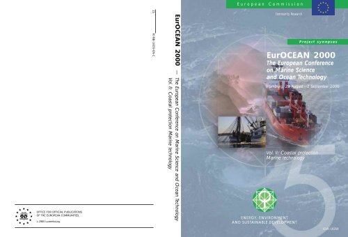
<strong>EurOCEAN</strong> <strong>2000</strong> — The European Conference on Marine Science and Ocean Technology<br />
Vol. II: Coastal protection Marine technology<br />
European Commission<br />
Community Research<br />
Vol. II: Coastal protection<br />
Marine technology<br />
ENERGY, ENVIRONMENT<br />
AND SUSTAINABLE DEVELOPMENT<br />
Project synopses<br />
<strong>EurOCEAN</strong> <strong>2000</strong><br />
The European Conference<br />
on Marine Science<br />
and Ocean Technology<br />
Hamburg, 29 August - 2 September <strong>2000</strong><br />
EUR 19359
Interested in European research?<br />
RTD info is our quarterly magazine keeping you in touch with main <strong>de</strong>velopments (results, programmes,<br />
events, etc). It is available in English, French and German. A free sample copy or free subscription<br />
can be obtained from:<br />
Directorate-General for Research, Communication Unit<br />
European Commission<br />
Rue <strong>de</strong> la Loi/Wetstraat 200, B-1049 Brussels<br />
Fax : (32-2) 29-58220<br />
E-Mail: research@cec.eu.int<br />
Internet: http://europa.eu.int/comm/research/<br />
EUROPEAN COMMISSION<br />
Research Directorate-General/D.I.3 - Energy, environment and sustainable <strong>de</strong>velopment<br />
Contact: Mr. Klaus - Günther BARTHEL - rue <strong>de</strong> la Loi, 200 (SDME 7/83), B-1049 Brussels<br />
Tel: (32-02 295 12 42) - Fax (32-02 296 30 24) E-mail: klaus-guenther.barthel@cec.eu.int
<strong>EurOCEAN</strong> <strong>2000</strong><br />
The European Conference<br />
on Marine Science<br />
and Ocean Technology<br />
Hamburg, 29 August - 2 September <strong>2000</strong><br />
Project Synopses<br />
Vol. II: Coastal protection - Marine technology
LEGAL NOTICE: Neither the European Commission nor any person acting on behalf of the Commission is responsible<br />
for the use which might be ma<strong>de</strong> of the following information.<br />
A great <strong>de</strong>al of additional information on the European Union is available on the Internet.<br />
It can be accessed through the Europa server (http://europa.eu.int).<br />
Cataloguing data can be found at the end of this publication.<br />
Luxembourg: Office for Official Publications of the European Communities, <strong>2000</strong><br />
ISBN 92-828-9714-1<br />
© European Communities, <strong>2000</strong><br />
Reproduction is authorised provi<strong>de</strong>d the source is acknowledged.<br />
Printed in Italy<br />
PRINTED ON WHITE CHLORINE-FREE PAPER
TABLE OF CONTENTS (Volumes I - II)<br />
Volume 1: Marine Processes, Ecosystems and Interactions..................................................1<br />
I.1 Marine systems research........................................................................................3<br />
I.1.1 Ciculation and exchange of water masses ............................................................3<br />
Variability of exchanges in the Northern seas (VEINS) ..............................................................5<br />
Tracing the water masses of the North Atlantic and<br />
the Mediterranean (TRACMASS) .............................................................................................10<br />
North Sea mo<strong>de</strong>l advection dispersion study 2: assessments<br />
of mo<strong>de</strong>l variability (NOMADS-II) ...........................................................................................16<br />
Comparative analysis and rationalisation of second moment<br />
turbulence mo<strong>de</strong>ls (CARTUM)..................................................................................................23<br />
I.1.2 Integrated ecosystem studies ...............................................................................29<br />
Cycling of Phosphorus in the Mediterranean (CYCLOPS) .......................................................31<br />
Role of microbial mats in bioremediation of hydrocarbon<br />
polluted coastal zones (MATBIOPOL)......................................................................................36<br />
The influence of UVR and climate conditions on fish stocks :<br />
A case study of the Northeast Artic cod (UVAC).....................................................................39<br />
Estimation of Primary Production for Fisheries Management<br />
(PROOF)...................................................................................................................................43<br />
Ocean margin exchange II - Phase II (OMEX II -PHASE II)....................................................49<br />
Ocean colour for the <strong>de</strong>termination of water column biological<br />
processes (BIOCOLOR) ............................................................................................................70<br />
Effect of nutrient ratios on harmful phytoplankton and<br />
their toxin production (NUTOX) ...............................................................................................76<br />
Molecular ecology of the Photosynthetic Procaryote Prochlorococcus,<br />
a key organism of oceanic ecosystems (PROMOLEC) .............................................................82<br />
Ecological effects of protection in Mediterranean marine reserves<br />
(ECOMARE) .............................................................................................................................91<br />
Processes of vertical exchange in shelf seas (PROVESS) .......................................................100<br />
The impact of appendicularia in European marine ecosystems (EURAPP).............................109<br />
III
Microbial assays for risk assessment (MARA)........................................................................112<br />
I.1.3 Marine biodiversity ............................................................................................119<br />
Monitoring Biodiversity of Pico-Phytoplankton in Marine Waters<br />
(PICODIV)...............................................................................................................................121<br />
Development and field validation of biosensor methods for the assessment<br />
of the effects of pollution and solar UV radiation on marine invertebrates.<br />
(UVTOX).................................................................................................................................128<br />
Biological control of harmful algal blooms in european coastal waters: role<br />
of eutrophication. (BIOHAB) ..................................................................................................135<br />
Microbial diversity in aquatic systems (MIDAS) ....................................................................139<br />
I.1.4 Marine biotechnology.........................................................................................145<br />
Lead potential of marine microorganisms from coastal, shelf and <strong>de</strong>ep sea<br />
sediments, a comparative assessment for optimized search strategies<br />
(MICROMAR).........................................................................................................................147<br />
Marine bacterial genes and isolates as sources for novel biotechnological<br />
Products (MARGENES) ..........................................................................................................153<br />
Biology of sponge natural products (SYMBIOSPONGE).......................................................159<br />
Marine cyanobacteria as a source for bioactive (apoptosis modifying)<br />
compounds with potential as cell biology reagents and drugs<br />
(Drugs from marine cyanobacteria) .........................................................................................164<br />
Methods to improve the supply of marine organisms for pharmaceutical<br />
related natural products chemistry (FAIRE) ............................................................................170<br />
I.1.5 Structure and dynamics of shelf ecosystems ....................................................173<br />
Influence of rising sea level on ecosystem dynamics of salt marshes (ISLED).......................175<br />
Atmospheric Nitrogen Inputs into the Coastal Ecosystem (ANICE) .......................................183<br />
Effects of climate induced temprerature change on marine coastal fishes<br />
(CLICOFI) ..............................................................................................................................190<br />
Submarine groundwater-fluxes and transport-processes from methane<br />
rich coastal sedimentary environments (SUB-GATE).............................................................197<br />
IV
Integrated nitrogen mo<strong>de</strong>l for european catchments (INCA)...................................................202<br />
Bridging effect assessment of mixtures to ecosystem situations and<br />
regulation (BEAM) ..................................................................................................................207<br />
Biogeochemical interactions between the Danube river and the<br />
Northwestern Black sea (EROS-21) ........................................................................................213<br />
Oceanographic application to eutrophication in regions of restricted exchange<br />
(OAERRE)...............................................................................................................................222<br />
Marine Effects of Atmospheric Deposition (MEAD) ..............................................................229<br />
Feed-backs of estuarine circulation and transport of sediments on phytobenthos<br />
(F-ECTS)..................................................................................................................................235<br />
Key coastal processes in the mesotrophic Skagerrak and the oligotrophic Northern<br />
Aegean: a comparative study (KEYCOP)................................................................................242<br />
Importance of organic matter from terrestrial sources for the production, community<br />
structure and toxicity of phytoplankton; role of micropredatos for transmission of<br />
toxins to commercial shellfish and fish larvae (DOMTOX) ....................................................251<br />
Effects of Eutrophicated seawater on rocky shore ecosystems studied in large littoral<br />
Mesocosms (EULIT)................................................................................................................258<br />
Long-term changes in Baltic Algal species and ecosystems (BIOBASE) ...............................267<br />
Statigraphical Development of the Glaciated European Margin (STRATAGEM)..................273<br />
I.1.6 Sedimentary processes .......................................................................................279<br />
Environmental Controls on Mound Formation along the European Margin<br />
(ECOMOUND)........................................................................................................................281<br />
The Mound Factory - Internal Controls (GEOMOUND).........................................................286<br />
Silicon cycling in the world ocean: the controls for opal preservation in the sediment<br />
as <strong>de</strong>rived from observations and mo<strong>de</strong>lling (SINOPS) ..........................................................293<br />
European marine sediment information network (EUMARSIN).............................................299<br />
I.2 Extreme ecosystems............................................................................................305<br />
Deep-sea Hydrothermal Vents: a Natural Pollution Laboratory (VENTOX) ..........................307<br />
Atlantic Coral Ecosystem Study (ACES).................................................................................310<br />
V
Sapropels and Palaeoceanography: palaeoceanographic, palaeoclimatic,<br />
palaeoenvironmental and diagenitic aspects of sapropel formation in the Eastern<br />
Mediterranean (SAP) ...............................................................................................................318<br />
Baltic Air-Sea-Ice study, a field experiment of Baltex (BALTEX-BASIS) ............................325<br />
I.3 Supporting initiatives.........................................................................................331<br />
European network for oceanographic data and information management<br />
(EURONODIM).......................................................................................................................333<br />
Mediterranean data archaeology and rescue of temperature, salinity and<br />
bio-chemical parameters (MEDAR) ........................................................................................341<br />
A searchable internet database of seabed samples from the ocean basins<br />
held at European institutions (EUROCORE)...........................................................................350<br />
Planning for a North West European Shelf Seas Ocean Data Assimilation<br />
and Forecast Experiment (ESODAE-Phase 1).........................................................................357<br />
Mediterranean mo<strong>de</strong>l networking and archiving program (MEDNET)...................................363<br />
National fleets of research vessels in Europe. Assessment of characteristics<br />
in comparison with future requirements (NATFLEET)...........................................................369<br />
Bergen Marine Food Chain research ingrastructure.................................................................372<br />
Volume 2 : Coastal Protection .............................................................................................379<br />
II.1.1 Coastal processes and morphodynamics ..............................................................381<br />
Surf and swash zone mechanics (SASME) ..............................................................................383<br />
Prediction of cohesive sediment transport and bed dynamics in estuaries<br />
and coastal zones with integrated numerical simulation mo<strong>de</strong>ls (COSINUS) .........................392<br />
Coastal study of 3-dimensional sand transport processes and morphodynamics<br />
(COAST3D).............................................................................................................................400<br />
Inlet dynamics initiative: Algarve (INDIA) .............................................................................407<br />
Sediment transport mo<strong>de</strong>lling in marine coastal environments (SEDMOC)...............................413<br />
VI
II.1.2 Mehtods for monitoring, forecasting and management of shelf seas<br />
and coastal zones ................................................................................................421<br />
Coastal region long-term measurements for colour remote sensing <strong>de</strong>velopment<br />
and validation (COLORS)........................................................................................................423<br />
Operational mo<strong>de</strong>lling for coastal zone management (OPCOM) ............................................430<br />
A European-wi<strong>de</strong> offshore/nearshore statistical toolbox for timely wave climate<br />
assessment (EUROWAVES) ...................................................................................................436<br />
European radar ocean sensing (EuroROSE) ............................................................................443<br />
Preparation and integration of analysis tools towards operational forecast of<br />
nutrients in estuaries of European rivers (PIONEER)..............................................................449<br />
Mediterranean forecasting system pilot project (MFSPP) ..........................................................457<br />
Assessment of antifouling agents in coastal environments (ACE)...........................................466<br />
Scour around coastal structures (SCARCOST)........................................................................474<br />
Validation of low level ice forces on coastal structures (LOLEIF)..........................................480<br />
The optimisation of crest level <strong>de</strong>sign of sloping coastal structures through<br />
prototype monitoring and mo<strong>de</strong>lling (OPTICREST)...............................................................487<br />
European shore platform erosion dynamics (ESPED) .............................................................495<br />
Volume 2 : Marine Technology.............................................................................................505<br />
III.1.1 Non-disturbing techniques.................................................................................507<br />
Automated i<strong>de</strong>ntification and characterization of marine microbial populations<br />
(AIMS).....................................................................................................................................509<br />
Sediment i<strong>de</strong>ntification for geotechnics by marine acoustics (SIGMA)..................................516<br />
Transmission of electromagnetic waves through sea water for imaging parameter<br />
measuring and communications (DEBYE) ..............................................................................524<br />
Improved microstructure measurement technologies for marine near surface flux<br />
studies (MITEC) ......................................................................................................................530<br />
Application of 3-dimensional electromagnetic induction by sources in the ocean<br />
(ISO-3D) ..................................................................................................................................540<br />
Automatic diatom i<strong>de</strong>ntification and classification (ADIAC)..................................................545<br />
VII
Subsea tools application research (STAR)...............................................................................552<br />
Dinoflagellate Categorisation by Artificial Neural Network (DiCANN).................................558<br />
III.1.2. Un<strong>de</strong>rwater communication and orientation...................................................565<br />
Longe range telemetry in ultra-shallow channels (LOTUS) ....................................................567<br />
Making seismic reflection profiles available to the wi<strong>de</strong>r scientific community<br />
(SEISCAN) ..............................................................................................................................575<br />
Shallow water acoustic communication network (SWAN)......................................................583<br />
Long range shallow water robust acoustic communication links (ROBLINKS) .....................588<br />
Un<strong>de</strong>rwater diving interpersonal communication and orientation system<br />
(UDICOS)...............................................................................................................................594<br />
Electroacoustic prototype for controlling the behaviour of marine mammals .........................600<br />
III.1.3 Un<strong>de</strong>rwater viewing ...........................................................................................605<br />
High resolution in-situ holographic recording and analysis of marine<br />
organisms and particles (HOLOMAR) ....................................................................................606<br />
III.1.4 Submarine geotechnics.......................................................................................615<br />
Grouted offshore piles for alternating loadings (GOPAL).......................................................617<br />
Very high resolution marine 3D seismic method for <strong>de</strong>tailed site<br />
investigation (VHR3D) ............................................................................................................624<br />
Advanced ROV package for automatic mobile inspection of sediments<br />
(ARAMIS) ...............................................................................................................................630<br />
A universersal docking-downloading-recharging system for AUVs<br />
(EURODOCKER)....................................................................................................................638<br />
Lightweight composite pressure housings for mid-water and Benthic applications<br />
(Composite Pressure Housings) ...............................................................................................645<br />
Advanced system integration for managing the coordinated operation<br />
of robotic ocean vehicles (ASIMOV) ......................................................................................649<br />
Geophysical and oceanographic station for abyssal research, 2nd phase:<br />
<strong>de</strong>ep sea scientific mission (GEOSTAR-2)..............................................................................658<br />
VIII
III.2.2 Oceanographic measurement and sampling equipment .................................667<br />
Hydrate autoclave coring equipment system (HYACE) ..........................................................669<br />
An autonomous system for monitoring air-sea fluxes using the inertial<br />
dissipation method and ship mounted instrumentation (AUTOFLUX) ...................................674<br />
Trace metals monitoring in surface marine waters and estuaries<br />
(Cd, Zn, Pb, Hg, Cu, Fe, Mn and Co) (MEMOSEA)...............................................................680<br />
Ocean tomography operational and utilization support (OCTOPUS)......................................687<br />
Spectroscopy using optical fibers in the marine environment (Sofie)......................................695<br />
Development and test of an innovative ion selective electro<strong>de</strong>s monitoring<br />
and control system for total nitrogen in marine waters .............................................................70<br />
IX
Volume II<br />
Coastal protection<br />
379
380
II.1.1. Coastal processes and morphodynamics<br />
381
382
TITLE: SURF AND SWASH ZONE MECHANICS :<br />
SASME<br />
CONTRACT NO: MAST3-CT97-0081<br />
COORDINATOR: Jørgen Fredsøe<br />
DHI Water and Environment<br />
Agern Allé 11<br />
DK-2970 Hørsholm, Denmark<br />
Tel: +45 45169200, Fax +45 45169292<br />
e-mail: jf@dhi.dk<br />
PARTNERS AND CONTACT PERSONS:<br />
Julio Zyserman<br />
DHI Water and Environment<br />
Agern Allé 11<br />
DK-2970 Hørsholm, Denmark<br />
Tel: +45 45169200, Fax +45 45169292<br />
jaz@dhi.dk<br />
Dano Roelvink<br />
Delft Hydraulics (DH)<br />
P.O. Box 177<br />
2600 MH Delft<br />
The Netherlands<br />
Tel: +31 15 285 8585, Fax: +31 15-285 8582<br />
Dano.Roelvink@wl<strong>de</strong>lft.nl<br />
Hans Dette<br />
Leichtweiss Institut für Wasserbau (LWI)<br />
Institut für Hydromechanik und<br />
Küsteningenieurwesen<br />
P.O.B. 3329<br />
Beethovenstrasse 51A<br />
D-38106 Braunschweig<br />
Germany<br />
Tel: +49 531-391-3930, Fax: +49 531-391-821<br />
H.Dette@tu-bs.<strong>de</strong><br />
Jesper Damgaard<br />
HR Wallingfor (HR)<br />
Coastal Group<br />
Howbery Park<br />
Wallingford, OXON OX10 8BA, UK<br />
Tel: +44 1491-835381,<br />
Fax: +44 1491-832233<br />
jsd@hrwallingford.co.uk<br />
Denis Aelbrecht<br />
Laboratoire National d´Hydraulique (LNH)<br />
EDF-LNH<br />
6. Quai Watier B.P. 49<br />
78401 Chatou Ce<strong>de</strong>x<br />
France<br />
Tel: +33 130-877412, Fax: +33 130-878086<br />
Denis.Aelbrecht@edfgdf.fr<br />
Rolf Deigaard<br />
Technical University of Denmark (DTU)<br />
Department of Hydrodynamics and Water<br />
Resources (ISVA), Building 115<br />
DK-2800 Lyngby, Denmark<br />
Tel: +45 45251422, Fax: +45 45936328<br />
rd@isva.dtu.dk<br />
383
Jan van <strong>de</strong> Graaff<br />
Delft University of Technology (DUT)<br />
Dept. of Civil Engineering<br />
Hydraulic and Offshore Engrg. Division<br />
P.O. Box 5048<br />
Stevinweg 1<br />
2628 CN Delft<br />
The Netherlands<br />
Tel: +31 15-278 4846, Fax: +31 15-278 5124<br />
J.van<strong>de</strong>Graaff@ct.tu<strong>de</strong>lft.nl<br />
D. Howell Peregrine<br />
University of Bristol (BrU)<br />
School of Mathematics<br />
University Walk<br />
Bristol BS8 1TW, England<br />
Tel: +44 117-928 7971, Fax: +44 117-928 7999<br />
D.H.Peregrine@bristol.ac.uk<br />
Paul A.D. Bird<br />
University of Plymouth (UPl)<br />
Faculty of Technology<br />
School of Civil and Structural Engineering<br />
Palace Court, Palace Street<br />
Plymouth<br />
Devon PL1 2DE, UK<br />
Tel: +44 1752-232534, Fax: +44 1752 232627<br />
pbird@plymouth.ac.uk<br />
Inigo J. Losada<br />
Universidad <strong>de</strong> Cantabria (UCa)<br />
Ocean & Coastal Research Group<br />
E.T.S.I. <strong>de</strong> Caminos, Canales y Puertos<br />
Av. <strong>de</strong> los Castros s/n<br />
39005 Santan<strong>de</strong>r, Spain<br />
Tel: +34 942-201810, Fax: +34 942-201860<br />
inigo@puer.unican.es<br />
384<br />
Albert Falques<br />
Universitat Politecnica <strong>de</strong> Catalunya<br />
(UPC)Dept. Fisica Aplicada<br />
Modul B5, Campus Nord UPCE-08034<br />
Barcelona, Spain<br />
Tel: +34 93 401 1831, Fax: +34 93 401 6090<br />
falques@fa.upc.es<br />
Marco Petti<br />
University of Udine (UUD)<br />
Dipartimento di Georisorse e TerritorioVia<br />
<strong>de</strong>l Contonificio, 114 33100 Udine, Italy<br />
Tel: +39 0432 558712,<br />
Fax: +39 0432 558700<br />
marco.petti@uniud.it<br />
Clive Greated<br />
The University of Edinburgh (UEDIN)<br />
Fluid Dynamics Unit<br />
Dept. of Physics and Astronomy<br />
Kings Building, Mayfield Road<br />
Edinburgh EH9 3JZ, UK<br />
Tel: +44 131-650-5232,<br />
Fax: +44 131-650-5220<br />
C.A.Greated@ed.ac.uk
SURF AND SWASH ZONE MECHANICS (SASME)<br />
J. FREDSØE<br />
DHI Water and Environment<br />
Agern Allé 11<br />
DK-2970 Hørsholm, Denmark<br />
B. MUTLU SUMER<br />
Technical University of<br />
Denmark (DTU)<br />
Department of Hydrodynamics<br />
and Water Resources (ISVA),<br />
Building 115<br />
DK-2800 Lyngby, Denmark<br />
JESPER DAMGAARD<br />
HR Wallingfor<br />
Coastal Group<br />
Howbery Park<br />
Wallingford, OXON OX10<br />
8BA, UK<br />
ROLF DEIGAARD<br />
Technical University of<br />
Denmark (DTU)<br />
Department of Hydrodynamics<br />
and Water Resources (ISVA),<br />
Building 115<br />
DK-2800 Lyngby, Denmark<br />
SUMMARY<br />
This MAST project started on 1 October 1997, and runs for 3 years. The<br />
total costs is estimated to be 2.895.000 ECU of which the EU contribution<br />
will be 1.810.000 ECU. The main aims of the project are <strong>de</strong>scribed, and<br />
the work plan is summarized. No results are yet available from the project.<br />
1. INTRODUCTION<br />
DANO ROELVINK<br />
Delft Hydraulics<br />
P.O. Box 177<br />
2600 MH Delft<br />
The Netherlands<br />
The objective of the present project is to investigate the physical processes which take place in<br />
the surf zone on a coast with and without coastal structures.<br />
The project shall lead to a significantly improved <strong>de</strong>scription of the cross-shore and longshore<br />
sediment transport, which mainly occurs within the surf zone.<br />
The SASME project is divi<strong>de</strong>d into two interlinked parts:<br />
I. Surf and swash zone hydrodynamics and sediment transport, and<br />
II. Surf and swash zone morphology.<br />
The surf and swash zone hydrodynamics and sediment transport will concentrate on the<br />
behaviour of breaking and broken waves, their generation of small and large scale turbulence,<br />
and the resulting sediment transport.<br />
The morphological study focus on the bed behaviour in the surf/swash zone which inclu<strong>de</strong>s<br />
bed-instabilities; formation of bars and their behaviour (like erosion and accretion in 2<br />
horizontal dimensions; non-uniformities in the alongshore direction due to rip currents).<br />
The far field impact of coastal structures is investigated: the effect of the modifications of<br />
wave, current and sediment transport fields by the structures. The project thus address<br />
important aspects of the function of the coastal structures. The project does not treat the three-<br />
385
dimensional near-field hydrodynamics and sediment transport around structures that are<br />
associated with local scour phenomena.<br />
In terms of practical outcome, the project is expected to produce significant improvements in<br />
“medium” term mo<strong>de</strong>lling, which is necessary for the <strong>de</strong>velopment of longer term prediction<br />
methods. In addition, improvements at a fundamental level will yield a basis for <strong>de</strong>velop-ments<br />
of transport and mixing mo<strong>de</strong>ls for quantities other than sediments in the surf and swash zones,<br />
plus some results of wi<strong>de</strong>r significance, for example in relation to breaking waves in <strong>de</strong>ep<br />
water and their significance for air-sea exchange and mixing.<br />
2. DESCRIPTION OF THE INDIVIDUAL PROJECTS<br />
SASME is divi<strong>de</strong>d into the following four main projects which each has a project lea<strong>de</strong>r and an<br />
assistant project lea<strong>de</strong>r. The 4 projects are:<br />
• Project 1. Breaking/broken waves in surf/swash zone. Project lea<strong>de</strong>r: Rolf Deigaard, DTU.<br />
• Project 2. Vertical structure of motion and associated sediment transport plus<br />
morphological mo<strong>de</strong>lling of coastal profiles. Project lea<strong>de</strong>r: B. Mutlu Sumer, DTU.<br />
• Project 3. Horizontal structure of wave- and breaker-induced motion and area-mo<strong>de</strong>lling.<br />
Project lea<strong>de</strong>r: Jesper Damgaard, HR.<br />
• Project 4. Structure-seabed interaction. Project lea<strong>de</strong>r: Dano Roelvink, DH.<br />
Project 1: Breaking and broken waves in the surf and swash zone<br />
Participants In the project: UPl, BrU, HR, DH, UUd, LWI, UCa, DHI, DTU.<br />
This project <strong>de</strong>al with waves just before they break, the processes of wave breaking and the<br />
further propagation as broken waves to the limits of the run-up in the swash zone. The study<br />
treats plane as well as barred coasts and aspects of hydrodynamics and sediment transport. The<br />
research has inclu<strong>de</strong>d analysis of field data, analysis of physical processes, mathematical<br />
mo<strong>de</strong>lling and laboratory experiments.<br />
Breaking and broken waves have been analysed from field data that have been ma<strong>de</strong> available<br />
for the project. The data are from locations in Germany: at the Baltic coast and at the North Sea<br />
coast (Sylt). The measurements have been specifically aimed at improving the physical<br />
un<strong>de</strong>rstanding of breaking processes, energy dissipation and the transformation of wave energy<br />
across the coastal profile. Field work has been carried out in Spain to study infra gravity waves<br />
especially in pocket beaches.<br />
The laboratory experiments inclu<strong>de</strong> a study of accelerated flow in porous media at high<br />
Reynolds numbers. Flume experiments have been carried out on breaking waves over<br />
permeable and impermeable beds. Extensive experiments have been carried out on swash zone<br />
conditions for different breaker types and beach slopes. The measurements inclu<strong>de</strong> among<br />
others surface elevations, run-up, the mean motion, turbulence intensity and the structure of the<br />
turbulence (length scales). The role of long waves for the dynamics of a surf zone has been<br />
investigated including the generation of long waves by a moving breakpoint. The interaction<br />
between breakpoint-generated and bound long waves has been investigated. Data has been<br />
386
available for plane and barred beaches. A theoretical study has been ma<strong>de</strong> on the generation of<br />
long waves from wave groups and the non-linear effect of long waves on short waves.<br />
The effects of wave reflection on surf zone dynamics have been studied by experimental and<br />
theoretical investigations.<br />
Boussinesq wave mo<strong>de</strong>ls for surf zone conditions have been verified against published data,<br />
including wave generated currents. Efficient 2DH mo<strong>de</strong>ls <strong>de</strong>scribing the vorticity generated by<br />
bores have been <strong>de</strong>veloped.<br />
Sediment transport in surf beat and long waves has been studied by numerical mo<strong>de</strong>ls verified<br />
against published data, and by analysis of hydrodynamic data from flume experiments to<br />
<strong>de</strong>termine zones of convergence and divergence. The theoretical study inclu<strong>de</strong>s the effect of<br />
bound long waves outsi<strong>de</strong> the breaker zone, surf zone wave mo<strong>de</strong>ls that resolve the low<br />
frequency motion but averages out the short waves, and by phase resolving wave mo<strong>de</strong>ls.<br />
The propagation of edge waves has been mo<strong>de</strong>lled for a plane beach with a shelf and a seawall<br />
to explain the formation of rhythmic morphology at a location in Spain. Work has continued<br />
with mo<strong>de</strong>lling of edge waves along a permeable barrier and resonance of a harbour un<strong>de</strong>r<br />
edge wave forcing.<br />
Project 2: Vertical structure of motion and associated sediment transport,<br />
and morphological mo<strong>de</strong>lling of coastal profiles<br />
The goal of the project is to study 3-D structures of wave-generated motions in the surf zone<br />
with focus on the large-scale vortices generated by plunging breakers, the turbulence<br />
generated by breaking and broken waves and the velocity distribution in wave-driven currents,<br />
and also to investigate morphological mo<strong>de</strong>lling of coastal profiles. Project 2 consists of two<br />
topics: (1) Vertical structure of wave- and breaker-induced motion and the associated sediment<br />
transport (Topics 1.2a - d); and (2) morphological mo<strong>de</strong>lling of the surf zone without structures<br />
(Topic 2.1a).<br />
Topic 1.2a. Description of a plunging breaker. The work has been concentrated on two<br />
aspects: (1) DHI/ISVA has been <strong>de</strong>veloping a mo<strong>de</strong>l for plunging breakers and to study the<br />
turbulent flow structures initiated by plunging breakers. (2) UEDIN in cooperation with ISVA<br />
has been doing PIV experiments of plunging breakers. The Volume of Fluid (VOF) method has<br />
been implemented in the general non-orthogonal Navier-Stokes solver in the DHI/ISVA work.<br />
Mo<strong>de</strong>l results have been compared to PIV measurements performed by UEDIN un<strong>de</strong>r waves<br />
breaking on a 1:13.5 slope. The k- mo<strong>de</strong>l has been used to mo<strong>de</strong>l the turbulence, and applied<br />
to simulate periodic breaking waves. All PIV experiments have been completed at two<br />
laboratories, at UEDIN and at ISVA. Different dynamics of selected breaker types have been<br />
found. The comparison of the mo<strong>de</strong>l results to measurements will be completed by the end of<br />
the project period.<br />
Topic 1.2b. Wave- boundary-layer investigation un<strong>de</strong>r breaking waves. An experimental<br />
study (ISVA) is being un<strong>de</strong>rtaken to study the interaction between turbulence generated by<br />
wave breaking, and the turbulence generated in an oscillatory boundary layer. The experiments<br />
are carried out in an oscillating water tunnel, and the wave-breaking generated turbulence is<br />
simulated by placing a grid in the upper part of the tunnel. The externally generated turbulence<br />
affects the transition to turbulence in the bed boundary layer, the phase difference between the<br />
free stream velocity and the bed shear stress and the wave friction factor. In another study at<br />
387
ISVA, turbulence un<strong>de</strong>r spilling breakers and broken waves has been investigated by wave<br />
flume experiments.<br />
Topic 1.2c. Influence of breaking waves on sediment transport. The work un<strong>de</strong>rtaken by<br />
DHI/ISVA un<strong>de</strong>r Topic 1.2a (see above), constitutes a key element for this research. The<br />
sediment transport has been inclu<strong>de</strong>d in an advanced Navier-Stokes solver in two-dimensions.<br />
DHI/ISVA will continue the <strong>de</strong>velopment of the free-surface method for breaking and broken<br />
waves. Also, comparison of the sediment transport rates to experimental results, and<br />
sensitivity analysis of for instance the fall velocity, will be ma<strong>de</strong>.<br />
Topic 1.2d. Wave-induced currents. The objective is to <strong>de</strong>velop a 3-D wave-driven current<br />
mo<strong>de</strong>l. A start has been ma<strong>de</strong> in testing the 3D implementation against 2D (laboratory) cases.<br />
Furthermore the present implementation has been combined with a research version which has<br />
on-line sediment transport module inclu<strong>de</strong>d. The wave effects are implemented in a co<strong>de</strong> that<br />
will also be used for morphological mo<strong>de</strong>lling of complex bathymetries. Testing of 3D<br />
implementation against 3D cases will be sought. The first comparisons have shown that<br />
especially the streaming effects are not yet inclu<strong>de</strong>d correctly. Research will focus on this<br />
aspect for the rest of the project period.<br />
Topic 2.1a. Morphological mo<strong>de</strong>lling of the surf zone without structures. Two research<br />
groups have been working on this topic, namely DHI and DH. The work DHI un<strong>de</strong>rtakes<br />
basically <strong>de</strong>als with vertical structure of motion and associated sediment transport plus<br />
morphological mo<strong>de</strong>lling of coastal profiles. A mathematical mo<strong>de</strong>l has been <strong>de</strong>veloped that<br />
<strong>de</strong>scribes the 3D distribution of the mean shear<br />
stress, the time varying eddy viscosity, velocity profiles, suspen<strong>de</strong>d sediment concentrations<br />
and sediment transport. The sediment transport mo<strong>de</strong>l has been exten<strong>de</strong>d to inclu<strong>de</strong> irregular<br />
wave trains. A phase resolving mo<strong>de</strong>l has been <strong>de</strong>veloped to simulate the morphological<br />
evolution of a cross-shore beach profile. The <strong>de</strong>pth averaged-hydrodynamics are calculated<br />
from a wave mo<strong>de</strong>l based on the Boussinesq equations. The Quasi 3D sediment transport<br />
mo<strong>de</strong>l has been incorporated into a phase averaged morphological mo<strong>de</strong>l for cross-shore<br />
profile evolution. The morphological mo<strong>de</strong>l has been used to investigate the morphological<br />
<strong>de</strong>velopment of beach profiles un<strong>de</strong>r the attack of obliquely inci<strong>de</strong>nt waves. Regarding the DH<br />
study un<strong>de</strong>r this topic, the objective is to mo<strong>de</strong>l the erosion/accretion of dry beaches in a<br />
morphodynamic area mo<strong>de</strong>l.The principle i<strong>de</strong>a is to extrapolate sediment transport from the<br />
last wet point to the highest dry point of a grid row or column, where transport is assumed to be<br />
a linear function of the height; in this way, profiles can uniformly shift in horizontal direction.<br />
A 1-D version of this approach has been successfully tested. Subsequently, a 2-D<br />
implementation has been carried out which has been tested successfully on the Keta Lagoon<br />
case.<br />
Project 3. Horizontal structure of wave- and breaker-induced motion and<br />
area mo<strong>de</strong>lling.<br />
Goal of the project: to investigate the hydrodynamics, sediment transport and morphodynamics<br />
in the surf and swash zone, with focus on the 2DH (two dimensions in the horizontal) view<br />
point. Most important results until now are as follows<br />
• for a realistic longshore current, in presence of eddy viscosity, resonant triads, which can<br />
involve unstable and/or stable mo<strong>de</strong>s, can exist and a resonant triad, comprising 3 linearly<br />
stable mo<strong>de</strong>s <strong>de</strong>rived from a linear stability analysis, can exhibit explosive instabilities.<br />
388
• the nearshore circulation mo<strong>de</strong>l SHORECIRC has been applied to study the infragravity<br />
wave response to the bathymetry and shortwave forcing. Specific attention has been paid<br />
to the generation of accurate boundary conditions for the bound incoming long wave.<br />
• a linear mo<strong>de</strong>l has been <strong>de</strong>veloped for the generation of long waves by obliquely inci<strong>de</strong>nt<br />
grouped short waves on an along-shore uniform beach. Effects of set-up and longshore<br />
currents on the long wave response are taken into account.<br />
• the <strong>de</strong>velopment of rip channels has been simulated with a 2DH numerical coastal area<br />
mo<strong>de</strong>l. The results for normal inci<strong>de</strong>nce exhibit significant scatter but compare relatively<br />
well with analytical results.<br />
• experiments have been carried out on the circulation current over a longshore bar with a<br />
rip channel. The relation bewtween the water level, the wave conditions and the maximum<br />
velocity in the rip current has been investigated.<br />
• the horizontal exchange of momentum in wave-driven currents and its importance for the<br />
velocity distribution has been invstigated. It is found that wave-current interaction can<br />
play an important role.<br />
• survey data from the test site Rantum, Sylt, North Sea has been finalised, behavioural<br />
trends of morphologic changes, rip currents and current systems have been <strong>de</strong>ducted.<br />
• a simplified linear mo<strong>de</strong>l for examining bar stability has now been <strong>de</strong>veloped. Results<br />
clearly indicate that a barred beach is less stable and will tend to exhibit instability.<br />
• a stability analysis and the investigation into the initial formation of rip channels on a<br />
long, straight and uniform longshore bar has been performed with a numerical mo<strong>de</strong>lling<br />
system.<br />
• the Coast3D test site of Egmond has been mo<strong>de</strong>lled using a 3D numerical mo<strong>de</strong>lling<br />
system.<br />
• a systematic exploration of the linear instability with simple <strong>de</strong>scriptions of sediment<br />
transport in case of oblique inci<strong>de</strong>nce has been achieved. Two behaviors are obtained<br />
<strong>de</strong>pending of the<br />
Project 4. Structure-seabed interaction<br />
Goal of this project: This project aims at un<strong>de</strong>rstanding, mo<strong>de</strong>lling and <strong>de</strong>scribing the effects of<br />
various coastal structures on the nearshore morphology. The project is divi<strong>de</strong>d into two topics:<br />
• mo<strong>de</strong>lling of the far field morphological evolution around structures, and<br />
• review of the experience on implementation of coastal structures.<br />
The mo<strong>de</strong>lling applied to the role of structures will profit by <strong>de</strong>velopments and improvements<br />
carried out in other parts of SASME. The capabilities and limitations of the different mo<strong>de</strong>lling<br />
principles for different types of structures are analysed. The mo<strong>de</strong>l results are used to analyse<br />
the flow, transport pattern and morphological <strong>de</strong>velopment around the structures, to obtain a<br />
better un<strong>de</strong>rstanding of the effect of the structures and of how a series of structures interacts.<br />
The aim of the review study is to provi<strong>de</strong> clear gui<strong>de</strong>lines on the use of coastal structure in<br />
coastline protection programmes. These gui<strong>de</strong>lines will be based on a review of existing<br />
experience with structures, and on the results of the <strong>de</strong>tailed mo<strong>de</strong>lling of the effects of<br />
structures during the SASME project. The gui<strong>de</strong>lines are recognised as one of the most<br />
important end products of SASME and will be published both in a <strong>de</strong>tailed report and as a<br />
review paper.<br />
389
Most important results until now:<br />
WL | <strong>de</strong>lft hydraulics (DH) has focused on the <strong>de</strong>scription of turbulence effects and 3D<br />
structure of<br />
transport and resulting morphological changes around harbours and long breakwaters (lit [1]).<br />
It is also investigating the effect of beach nourishments. It will also do some <strong>de</strong>pth-averaged<br />
runs for situations with groins for comparison with LNH's 3D approach<br />
Danish Hydraulic Institute (DHI) looks at the morphological evolution around emerged and<br />
submerged offshore breakwaters with 2DH and quasi3D approaches (lit [2]), and investigates<br />
the effects of diffraction and directional spreading.<br />
Laboratoire Nationale d' Hydraulique (LNH) investigates the effects of groins using a 3D<br />
approach (lit [3]).<br />
Delft University of Technology (DUT) has looked into the effects of submerged breakwaters<br />
and is now investigating the equilibrium shape of natural bays and bays formed between<br />
offshore breakwaters, using a 2DH approach (lit [4]).<br />
390
Together the partners span most types of structures. In a collaboration between all partners, the<br />
processes around these structures and the state of the art (including present improvements) of<br />
mo<strong>de</strong>lling these processes will be <strong>de</strong>scribed in a review paper. A review paper on the practical<br />
use of structures and morphological <strong>de</strong>sign consi<strong>de</strong>rations is being prepared.<br />
_____________<br />
SASME homepage with a lot of additional information: www.wl<strong>de</strong>lft.nl/sasme/sasme.htm<br />
391
TITLE : PREDICTION OF COHESIVE SEDIMENT<br />
TRANSPORT AND BED DYNAMICS IN<br />
ESTUARIES AND COASTAL ZONES WITH<br />
INTEGRATED NUMERICAL SIMULATION<br />
MODELS: COSINUS<br />
CONTRACT N° : MAS3 CT97-0082<br />
COORDINATOR : Prof. Jean E. Berlamont<br />
Hydraulics Laboratory, Katholieke Universiteit Leuven,<br />
<strong>de</strong> Croylaan 2, B 3001 Leuven, Belgium.<br />
Tel: +32 16 321660<br />
Fax: +32 16 321989<br />
E-mail: jean.berlamont@bwk.kuleuven.ac.be<br />
PARTNERS :<br />
Dr Ole Petersen Dr Damien Violeau<br />
Danish Hydraulic Institute Electricité <strong>de</strong> France<br />
DHI Water and Environment Laboratoire National d’Hydraulique et <strong>de</strong><br />
L’Environnement (LNHE)<br />
Agern Allé 11 Quai Wattier 6<br />
DK-2970 Horsholm, Denmark F – 78401 Chatou, France<br />
Tel. : +45-45-169200 Tel. : +33-1-30-877255<br />
Fax : +45-45-169292 Fax : +33-1-30-878086<br />
E-mail : Osp@dhi.dk E-mail : damien.violeau@edf.fr<br />
Prof. Mark Markofsky Dr Johan C. Winterwerp<br />
Universität Hannover (UHA) Technische Universiteit Delft (TUD)<br />
Institut für Strömungsmechanik Dept. of civil engineering<br />
Appelstrasse 9a Stevinweg 1<br />
D-30169 Hannover, Deutschland NL-2628 CN Delft, Ne<strong>de</strong>rland<br />
Tel. : +49-511-762.3776 Tel. : +31-15-2781971<br />
Fax : +49-511-762.3777 Fax : +31-15-2785975<br />
E-mail : mark@hydromech.uni-hannover.<strong>de</strong> E-mail : h.winterwerp@ct.tu<strong>de</strong>lft.nl<br />
Prof. Keith Dyer Dr Hervé Michallet<br />
University of Plymouth (UPL) Université Joseph Fourrier, Grenoble (UJF)<br />
Institute of Marine Studies Laboratoire <strong>de</strong>s Ecoulements Geophysiques &<br />
Drake Circus Industriels (LEGI)<br />
Plymouth PL4 8AA, UK BP 53<br />
F-38041 Grenoble Cé<strong>de</strong>x 9, France<br />
Tel. : +44-1752-232420 Tel.: +33-476825060<br />
Fax : +44-1752-232406 Fax : +33-476825001<br />
E-mail : K.Dyer@plymouth.ac.uk E-mail: michalle@hmg.inpg.fr<br />
392
Dr Johan C. Winterwerp Dr Gilliane Sills<br />
Delft Hydraulics (DH) University of Oxford (UOX)<br />
P.O. Box 177 Department of Engineering Science<br />
Nl-2600 MH Delft, Ne<strong>de</strong>rland Parks Road<br />
Tel. : +31-15-2858813 Oxford OX1 3PJ, UK<br />
Fax : +31-15-2858710 Tel. : +44-1865-273164<br />
E-mail : han.winterwerp@wl<strong>de</strong>lft.nl Fax : +44-1865-273907<br />
E-mail : Gilliane.Sills@eng.ox.ac.uk<br />
.<br />
Dr Bill Roberts<br />
H.R. Wallingford,<br />
Howbery Park<br />
Wallingford 0X10 8BA, U.K.<br />
Tel.: +44-1491-835381<br />
Fax: +44-1491-832233<br />
Email: wr@hrwallingford.co.uk<br />
393
394<br />
PREDICTION OF COHESIVE SEDIMENT TRANSPORT AND BED<br />
DYNAMICS IN ESTUARIES AND COASTAL ZONES WITH<br />
INTEGRATED NUMERICAL SIMULATION MODELS<br />
Jean Berlamont 1 , Erik Toorman 1 , Keith Dyer 2 , Han Winterwerp 3 , Bill Roberts 4 , Damien<br />
Violeau 5 ,<br />
Mark Markofsky 6<br />
1 Katholieke Universiteit Leuven, Belgium; 2 University of Plymouth, U.K.;<br />
3 Delft Hydraulics and TUDelft, the Netherlands; 4 HR. Wallingford, U.K; 5 Electricité <strong>de</strong><br />
France, LNHE, France; 6 Universität Hannover, Germany<br />
INTRODUCTION<br />
The management of coastal zones and estuaries requires accurate and <strong>de</strong>tailed knowledge to<br />
cope with their problems such as wetland protection and restoration, maintenance of navigation<br />
channels, dredging and dredged material relocation, effects of construction works on siltation<br />
and turbidity levels, pollutant transport, etc. Development and application of this knowledge<br />
requires <strong>de</strong>tailed mathematical mo<strong>de</strong>ls, amongst which full three-dimensional co<strong>de</strong>s. This is<br />
becoming practically feasible in view of the current <strong>de</strong>velopments in soft- and hardware. The<br />
physical un<strong>de</strong>rstanding and mathematical <strong>de</strong>scription or “mo<strong>de</strong>lling” of the processes however<br />
is still lagging behind, especially with respect to the presence of concentrated benthic (nearbed)<br />
suspension layers (CBS).<br />
PROJECT METHODOLOGY<br />
The state of the art knowledge on cohesive sediment transport shows that there is still a lack of<br />
experimental data on the role of flocculation and turbulence in the formation and erosion of<br />
mud beds and on the formation of CBS (concentrated benthic suspensions, or “fluid mud”).<br />
Therefore, an experimental programme has been set up to obtain these data. It consisted of<br />
field measurements in the Tamar estuary on floc formation and laboratory experiments on<br />
formation and erosion of mud beds and CBS, and the influence of floc structure and turbulence<br />
on these processes.<br />
The data of the experimental programme, together with other relevant data from literature have<br />
been stored in a database, which at the end of the project will be accessible to the public.<br />
Process modules have been <strong>de</strong>veloped and implemented into <strong>de</strong>tailed 1D and 2D vertical<br />
mo<strong>de</strong>ls which solve the full hydrodynamic, turbulent energy and sediment mass conservation<br />
equations. Two different bed mo<strong>de</strong>ls, to be coupled to these hydrodynamic mo<strong>de</strong>ls have been<br />
<strong>de</strong>veloped as well (1DV point mo<strong>de</strong>l). The data from the database have been used to calibrate<br />
and validate the process modules.<br />
The process modules have been parameterised to obtain relatively simple formulations, which<br />
can be implemented into currently used 3D and 2DH engineering system mo<strong>de</strong>ls.<br />
The performance of the improved system mo<strong>de</strong>ls has been tested by application of the mo<strong>de</strong>ls<br />
to a schematic estuary, for which a 2DV solution with the <strong>de</strong>tailed research mo<strong>de</strong>l is used as a<br />
reference. Various scenarios have been simulated. The mo<strong>de</strong>ls have also been applied to three
eal estuaries ( Tamar, Loire and Weser). Data to set-up and calibrate the mo<strong>de</strong>l applications<br />
are stored in the database. From the experience with the large-scale applications feed back has<br />
been produced towards the process module <strong>de</strong>velopment and their parameterisations.<br />
RESULTS<br />
Sediment - turbulence interaction<br />
For the numerical mo<strong>de</strong>lling of sediment - turbulence interaction, the most commonly used<br />
engineering turbulence mo<strong>de</strong>ls have been used, i.e. the Prandtl mixing length (PML) and the kε<br />
mo<strong>de</strong>l.<br />
Suspen<strong>de</strong>d sediment particles cause damping of turbulent energy in the flow. Traditionally, this<br />
effect is parameterised by the use of semi-empirical damping functions, which are applied to<br />
correct the turbulent eddy viscosity (in the PML mo<strong>de</strong>l) and the sediment mixing coefficient<br />
(or eddy diffusivity) for neutral conditions. The k-ε mo<strong>de</strong>l inclu<strong>de</strong>s the buoyancy effect<br />
explicitly but still needs the damping functions in the bed boundary conditions and the<br />
buoyancy term. Data on turbulence damping in stratified flows from the literature have been<br />
reanalysed, together with numerical data generated with the k-ε mo<strong>de</strong>l. Based on these results<br />
and on theoretical consi<strong>de</strong>rations, new damping functions have been proposed and tested.<br />
High <strong>de</strong>nsity gradients at the bed result in an apparent reduction of the bottom roughness with<br />
consequently higher transport and erosion rates than expected when the mo<strong>de</strong>l would not<br />
account for these buoyancy effects in the bed boundary conditions. A new bottom boundary<br />
treatment method has been proposed, which yields the correct bed shear stress.<br />
When a flowing suspension <strong>de</strong>celerates during a tidal cycle, hin<strong>de</strong>red settling may lead to the<br />
formation of a two-layer stratified flow with a distinct <strong>de</strong>nsity interface, the lutocline.<br />
Turbulence can be completely suppressed at this interface, as a result of which no sediment can<br />
be suspen<strong>de</strong>d in the upper layer, increasing the amount of sediment in the lower layer further.<br />
Hence a snow-ball effect occurs resulting in a collapse of the turbulence field and the vertical<br />
concentration profile. Un<strong>de</strong>r certain conditions this interface becomes unstable, resulting in<br />
internal waves which generate new turbulence and mixing across the lutocline. It has been<br />
proposed to mo<strong>de</strong>l this turbulence generation in a parameterised form as an additional eddy<br />
viscosity. An experimental and theoretical study was carried out to establish the effects of nonlocally<br />
produced turbulence on the mixing<br />
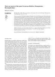
Ratio of the mixing to the momentum damping function (or normalised inverse<br />
Schmidt number) as a function of the gradient Richardson number (symbols =<br />
various data from the literature, fine line = Munk & An<strong>de</strong>rson (1948), dashed<br />
line = Ellison (1956), dotted line = Kranenburg (1999), thick line = new<br />
proposal)<br />
Fs/Fm<br />
1<br />
0.8<br />
0.6<br />
0.4<br />
0.2<br />
0<br />
0.001 0.01 0.1 1 10 100<br />
Ri<br />
395
processes of CBS. This is particularly relevant in case of spatially confined occurrences of<br />
CBS/fluid mud, as often encountered in nature.<br />
Flocculation<br />
Because, as far as cohesive suspensions are concerned, laboratory experiments cannot scale the<br />
turbulent properties of natural flows a<strong>de</strong>quately, field measurements were obtained of floc<br />
characteristics. The measurements were taken in September 1998 in the upper reaches of the<br />
Tamar Estuary, and covered the neap and spring ti<strong>de</strong> conditions. In that location the turbidity<br />
maximum is well <strong>de</strong>veloped and suspension concentrations of or<strong>de</strong>r g/l are present. The aim of<br />
the experiment was to measure floc size and settling velocity and their <strong>de</strong>pen<strong>de</strong>nce on salinity,<br />
concentration and turbulent shear.<br />
Two stations about 1km apart in the centre of the channel were <strong>de</strong>ployed simultaneously. At<br />
both stations frequent profiles of velocity, salinity, temperature, and suspen<strong>de</strong>d sediment<br />
concentration were obtained, and Owen tube measurements of settling velocity were taken. At<br />
the lower station profiles of floc size were taken with a Lasentec P-100 system (Law et al.,<br />
1997), and near bed measurements of floc size, settling velocity, and effective <strong>de</strong>nsity obtained<br />
with the INSSEV instrument (Fennessy et al., 1994). Also turbulence parameters were<br />
measured with miniature electromagnetic flowmeters above and below the INSSEV. At the<br />
upper station a LISST laser diffraction particle sizer was <strong>de</strong>ployed, vi<strong>de</strong>o measurement of floc<br />
size and settling velocities were observed within Owen tube samples. Additionally, samples<br />
were taken for laboratory analysis of the carbohydrate and chlorophyll a contents and CHN<br />
ratios.<br />
Suspen<strong>de</strong>d near bed sediment concentrations ranged from 16 mg/l on a neap ti<strong>de</strong> to 7 g/l on a<br />
spring ti<strong>de</strong>. Maximum velocities were 0.5 and 1.5 m/s, respectively. Typical spring ti<strong>de</strong> shear<br />
stresses were 0.68 N/m 2 at the level of the INSSEV. The number of flocs per INSSEV sample<br />
varied between 14 and 1150. Floc sizes up to 600 microns were observed. Examination of the<br />
settling velocity spectra of the flocs has indicated that the settling velocity Ws can be<br />
represented in simple linear correlation by: Ws = 5.784 (Shear) 0.606 and Ws = 0.524 (SPM) 0.249 ,<br />
where Ws is in mm/s, shear is in N/m 2 and SPM in mg/l. Also the ratio of macroflocs to<br />
396<br />
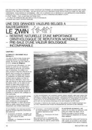
Settling velocity (Ws) mm/sec<br />
10<br />
1<br />
0.1<br />
Selected spring & neap ti<strong>de</strong> INSSEV mean macrofloc (greater than 160 microns)<br />
settling velocities plotted against both shear stress and SPM (0.5 m above the seabed)<br />
Ws = 5.7841SHEAR 0.6063<br />
R 2 = 0.7331<br />
Shear stress SPM<br />
Ws = 0.5242 SPM 0.2489<br />
R 2 = 0.7757<br />
0.01 0.1 1 10 100 1000 10000<br />
Shear stress (N/m^2) Suspen<strong>de</strong>d Particulate Matter (SPM) mg/l
microflocs separated at a size of 160 microns was observed to increase with both increasing<br />
concentration and shear stress. This suggests that the influence of concentration on aggregation<br />
is greater than that of shear on floc break-up. The biochemical results suggest that high<br />
carbohydrate levels acts as an adhesive assisting the production of the larger faster settling<br />
macroflocs formed during low concentrations at neap ti<strong>de</strong>s. It also appears that the faster<br />
settling macroflocs can selectively scavenge the very small microflocs at a rate faster than that<br />
for the medium sized flocs. Lower organic and chlorophyll-a content sediment is ero<strong>de</strong>d from<br />
the bed at spring ti<strong>de</strong>s, reducing the contents observed at neap ti<strong>de</strong>s.<br />
A 3D flocculation mo<strong>de</strong>l in an Eulerian frame, <strong>de</strong>scribing turbulence induced aggregation and<br />
floc break-up, has been <strong>de</strong>veloped. The flocs are <strong>de</strong>scribed as self-similar fractal entities. The<br />
mo<strong>de</strong>l is calibrated against experimental data reported in the literature and <strong>de</strong>ployed to <strong>de</strong>scribe<br />
the processes in the turbidity maximum on the Ems estuary (The Netherlands). Observed<br />
variations in vertical concentration distributions could be predicted only when both<br />
flocculation and sediment-induced buoyancy effects are taken into account.<br />
CBS dynamics<br />
In 2D mo<strong>de</strong>ls, the mo<strong>de</strong>lling of entrainment is important. From flume experiments is has been<br />
found that<br />
- due to generation of turbulence in the lower, <strong>de</strong>nse CBS layer, material from the upper,<br />
less <strong>de</strong>nse and less turbulent layer is entrained into the lower layer, which thickened<br />
accordingly.<br />
- the entrainment velocity appears to be constant in time, which is consistent with theory.<br />
- a freshly <strong>de</strong>posited CBS behaves as a viscous fluid<br />
- A relationship of the form E a 1/Ri* was found, in which E is the dimensionless<br />
entrainment rate and Ri* the overall Richardson number.<br />
From grid tank experiments the formation of CBS layers reaching an equilibrium thickness was<br />
observed for different concentration conditions. The time averaged sediment concentration<br />
appears to be uniform in the CBS layer for all concentrations. The turbulent kinetic energy<br />
<strong>de</strong>creases with increasing distance from the grid. No <strong>de</strong>cay of turbulent kinetic energy was<br />
found for sediment concentrations up to 200 g/l. The flux Richardson number below the<br />
lutocline varies by more than two or<strong>de</strong>rs of magnitu<strong>de</strong> when the variations of the settling<br />
velocity versus the concentration was taken into account.<br />
Bed dynamics<br />
Extensive settling column experiments have been used to <strong>de</strong>velop and verify numerical mo<strong>de</strong>ls<br />
of the consolidation process. The relationship between the properties of the settling flocs, the<br />
<strong>de</strong>position rates and the properties of the <strong>de</strong>posited bed (in particular the consolidating <strong>de</strong>nsity<br />
profile and strength <strong>de</strong>velopment) have been investigated. Using in situ measurements the<br />
critical shear stress for erosion has been related to other properties.<br />
A 1DV sedimentation-consolidation mo<strong>de</strong>l, solving the classical Gibson equation in an<br />
Eulerian frame, has been <strong>de</strong>ployed to simulate the hin<strong>de</strong>red settling and consolidation process<br />
in an annular flume. Material functions and strength evolution are <strong>de</strong>scribed using fractal<br />
theory. The mo<strong>de</strong>l has been exten<strong>de</strong>d to inclu<strong>de</strong> the effects of sand-mud mixtures in the case of<br />
small sand fractions.<br />
A 2DV bed dynamics mo<strong>de</strong>l based on the generalised Biot theory, exten<strong>de</strong>d to <strong>de</strong>al with<br />
extremely large <strong>de</strong>formations and corresponding <strong>de</strong>nsity changes, has been <strong>de</strong>veloped to study<br />
the strength <strong>de</strong>velopment in cohesive sediment beds during consolidation, fluidisation and<br />
397
liquefaction (e.g. induced by wave action). The mo<strong>de</strong>l allows the implementation of more<br />
realistic constitutive rheological equations (i.e. stress – strain relationships).<br />
With regard to <strong>de</strong>position/ erosion the use of a new empirical stress – <strong>de</strong>nsity relationship has<br />
been proposed which accounts for the fact that no strength is <strong>de</strong>veloped below the gelling point<br />
of the mud. The erosion rate parameter is proposed to be a function of the bed surface <strong>de</strong>nsity.<br />
For <strong>de</strong>position the total settling flux is consi<strong>de</strong>red, i.e. no critical stress for <strong>de</strong>position. In or<strong>de</strong>r<br />
to distinguish between the settling sediment, which attaches to the bed and the <strong>de</strong>posited<br />
sediment which remains mobile and can readily be entrained, the erosion law has been<br />
generalised.<br />
Applied mo<strong>de</strong>lling<br />
The goal of the “Applied Mo<strong>de</strong>lling” was to provi<strong>de</strong> results using numerical mo<strong>de</strong>ls, including<br />
the knowledge resulting from the theoretical aspects of the project. For this purpose, various<br />
test cases have been <strong>de</strong>fined, in or<strong>de</strong>r to test and validate the new formulations, and to compare<br />
the different numerical mo<strong>de</strong>ls. The final goal is to apply the mo<strong>de</strong>ls to the cases of real<br />
estuaries, to show their capability to reproduce actual cohesive sediment phenomena.<br />
The first test case is a one-dimensional vertical case, <strong>de</strong>signed to compare the mo<strong>de</strong>ls regarding<br />
vertical processes, and particularly the mo<strong>de</strong>lling of turbulence damping by suspen<strong>de</strong>d<br />
sediment. Several sets of conditions for hydrodynamics and sediment have been tested. The<br />
computed results show that stratification and saturation effects are very sensitive to the choice<br />
of damping functions. It appears, looking at the viscosity and diffusivity profiles, that the<br />
influence of the shear velocity at the bottom is an important parameter to make correct<br />
sediment transport predictions. However, theoretical work has shown that the shear velocity is<br />
not correctly estimated by traditional methods when sediment is involved. Therefore a new<br />
formulation has been proposed.<br />
Experimental and theoretical studies of flocculation processes have produced new information,<br />
which has been used to <strong>de</strong>velop parameterisations of the sediment settling velocity. Several<br />
approaches exist, which have been implemented in the one-dimensional mo<strong>de</strong>l. Comparisons<br />
and sensitivity tests have been carried out. On the other hand, the effects of entrainment of bed<br />
materials, resulting from the instability of the lutocline, have also been examined. A<br />
parameterisation has been established, which has been tested in the numerical mo<strong>de</strong>ls.<br />
Similarly, the results of <strong>de</strong>tailed studies of bed properties have been used to consi<strong>de</strong>r<br />
parameterised representations of the bed. There are two main aspects to this: consolidation of<br />
bed <strong>de</strong>posits and erosion. The mo<strong>de</strong>l <strong>de</strong>veloped for consolidation is a variant of the Gibson<br />
equation based on a fractal representation of the floc structure (Winterwerp, 1999). It has been<br />
tested in the one-dimensional mo<strong>de</strong>l. Resistance of the bed to erosion is a crucial parameter in<br />
the mo<strong>de</strong>lling of cohesive sediment transport, but less well un<strong>de</strong>rstood. Based on experimental<br />
results and theory new formulations have been proposed and incorporated in the mo<strong>de</strong>l<br />
parameterisation.<br />
Simulations have been carried out with a second test case, a schematic estuary, consi<strong>de</strong>red as a<br />
two-dimensional vertical mo<strong>de</strong>l. The results will prove the ability of the parameterisation<br />
<strong>de</strong>veloped to represent correctly the cohesive sediment processes when including advection<br />
and realistic estuarine processes, such as unsteady tidal hydrodynamic forcing, river<br />
discharges, and stratification due to salinity.<br />
Finally, simulations have been carried out in the cases of three different real estuaries: the<br />
Weser, the Tamar, and the Loire estuaries. To validate the mo<strong>de</strong>l results, these are compared<br />
with extensive experimental data from the three estuaries, partly collected during the project.<br />
The comparison between the mo<strong>de</strong>ls results and these experimental data show that it is now<br />
possible to predict cohesive sediment processes correctly in real estuaries.<br />
All data have been stored in a data base, which is accessible to the public.<br />
398
CONCLUSIONS<br />
The objective of the research programme was to establish well validated physical and<br />
mathematical <strong>de</strong>scriptions of the behaviour and fate of concentrated near-bed suspensions<br />
(CBS or «fluid mud») and their interaction with the water and the sediment bed.<br />
An experimental programme has been set up to obtain missing data on floc formation, the<br />
formation of mud beds and CBS and the influence of floc structure and turbulence on these<br />
processes.<br />
Different processes have been studied in <strong>de</strong>tail: turbulence damping in sediment la<strong>de</strong>n flow;<br />
turbulence production due to internal waves in concentrated suspensions; flocculation;<br />
generation, properties and entrainment of CBS; bed strength <strong>de</strong>velopment and erosion of mud<br />
beds.<br />
The <strong>de</strong>tailed process mo<strong>de</strong>ls have been parameterised to obtain relatively simple formulations<br />
which can be plugged in into currently used 3D and 2DH engineering system mo<strong>de</strong>ls.<br />
The performance of the improved system mo<strong>de</strong>ls has been tested by application of the mo<strong>de</strong>ls<br />
to a schematic estuary for which 2DV solutions with the <strong>de</strong>tailed research mo<strong>de</strong>ls were used as<br />
a reference.<br />
The mo<strong>de</strong>ls have been applied and tested in three real estuaries (Tamar in U.K., Loire in<br />
France and Weser in Germany).<br />
All data have been stored in a data base, which is accessible to the public.<br />
It is felt that great progress has been ma<strong>de</strong> in the physically based <strong>de</strong>scription of cohesive<br />
sediment dynamics with respect a.o. to the formulation of turbulence damping functions; the<br />
mo<strong>de</strong>lling of the rheology of CBS, incl. consolidation; the mo<strong>de</strong>lling of flocculation and the<br />
mo<strong>de</strong>lling of erosion and entrainment of CBS.<br />
Engineering software tools have been improved to enable better predictions of mud dynamics<br />
for the benefit of estuarine an coastal managers.<br />
REFERENCES<br />
Several papers will be presented at the INTERCOH <strong>2000</strong> conference, Delft September 4 – 8,<br />
<strong>2000</strong>. The conference will coinci<strong>de</strong> with the closure of the COSINUS project. Besi<strong>de</strong>s<br />
individual papers, joint papers <strong>de</strong>scribing the achievements within the different tasks will be<br />
presented. Most of the scientific progress achieved within COSINUS will thus be published in<br />
the proceedings of INTERCOH <strong>2000</strong>.<br />
More <strong>de</strong>tailed information can also be found on the COSINUS internet site:<br />
http://sun-hydr-01.bwk.kuleuven.ac.be/COSINUS/cosinus.html<br />
Fennessy, M.J., K.R. Dyer & D.A. Huntley (1994). “INSSEV: an instrument to measure the<br />
size and settling velocity of flocs in situ”. Marine Geology 177:107-117.<br />
Law, D.J., A.J. Bale & S.E. Jones (1997). “Adaptation of focused beam reflectance<br />
measurement to in-situ particle sizing in estuaries and coastal waters”. Marine Geology<br />
140:47–59.<br />
Winterwerp J. (1999). “On the dynamics of high-concentrated mud suspensions”. PhD thesis,<br />
T.U.Delft.<br />
399
TITLE : COASTAL STUDY OF THREE-DIMENSIONAL<br />
SAND TRANSPORT PROCESSES AND<br />
MORPHODYNAMICS : COAST-3D<br />
CONTRACT N° : MAS3-CT97-0086<br />
COORDINATOR : Mr Richard Soulsby<br />
Marine Sediments Group<br />
HR Wallingford Ltd, Howbery Park<br />
Wallingford, Oxfordshire<br />
OX10 8BA,UK<br />
Tel : +44 1491 822233<br />
Fax : +44 1491 825743<br />
Email : rls@hrwallingford.co.uk<br />
PARTNERS :<br />
Dr Piet Hoekstra<br />
Department of Physical Geography<br />
Institute for Marine and Atmospheric<br />
Research<br />
University of Utrecht<br />
Postbus 80.115<br />
Hei<strong>de</strong>lberglaan 2<br />
NL - 3508 TC Utrecht<br />
Ne<strong>de</strong>rland<br />
Tel: +31 30 2532753<br />
Fax: +31 30 2540604<br />
Email: p.hoekstra@frw.ruu.nl<br />
Dr Jan Mul<strong>de</strong>r<br />
Ministerie van Verkeer en Waterstaat<br />
Rijksinstituut <strong>voor</strong> Kust en <strong>Zee</strong><br />
Kortenaerka<strong>de</strong> 1<br />
Postbus 20907<br />
Den Haag<br />
NL-2500 EX<br />
Ne<strong>de</strong>rland<br />
Tel: +31 70 3114234<br />
Fax: +31 70 3114321<br />
Email:J.P.M.Mul<strong>de</strong>r@rikz.rws.minvenw.nl<br />
400<br />
Professor Dr Leo van Rijn<br />
Delft Hydraulics<br />
Marine and Coastal Management<br />
PO Box 177<br />
NL-2600 MH Delft<br />
The Netherlands<br />
Tel: +31 15 2858898<br />
Fax: +31 15 2858710<br />
Email: Leo.vanRijn@wl<strong>de</strong>lft.nl<br />
Professor David Huntley<br />
Institute of Marine Studies<br />
University of Plymouth<br />
Drake Circus<br />
Plymouth<br />
Devon<br />
GB - PL4 8AA<br />
Tel: +44 1752 232431<br />
Fax: +44 1752 232406<br />
Email: D.Huntley@plymouth.ac.uk
Professor Brian O’Connor<br />
The University of Liverpool<br />
Department of Civil Engineering<br />
Brownlow Hill<br />
Liverpool<br />
GB-L69 3BX<br />
Tel: +44 151 794 5232<br />
Fax: +44 151 794 5218<br />
Email: price@liverpool.ac.uk<br />
Dr Peter D Thorne<br />
Proudman Oceanographic Laboratory<br />
Bidston Observatory<br />
Birkenhead<br />
Merseysi<strong>de</strong><br />
GB-L43 7RA<br />
Tel: +44 151 653 8633<br />
Fax: +44 151 653 6269<br />
Email: pdt@pol.ac.uk<br />
Dr Franck Levoy<br />
Universite <strong>de</strong> Caen<br />
Laboratoir <strong>de</strong> Geologie Marine - Centre<br />
Regional D’Etu<strong>de</strong>s Cotieres<br />
BP 49<br />
54 Rue Du Dr Charcot<br />
F-14530<br />
LUC-SUR-MER<br />
Tel: +33 2 31 36 22 22<br />
Fax: 33 2 31 36 22 20<br />
Email: levoy@neptune.msh.unicaen.fr<br />
Professor Dr Agustin Sanchez-Arcilla<br />
Laboratori D’Enginyeria Maritima<br />
Universistat Politecnica De Catalunya<br />
C/ Gran Capita S/N<br />
Campus Nord UPC, Mod. D1<br />
ES-08034<br />
Barcelona<br />
Spain<br />
Tel: +34 93 401 6468<br />
Fax: +34 93 401 6019<br />
Email: arcilla@etseccpb.upc.es<br />
Dr Jean Lanckneus<br />
MAGELAS BVBA<br />
Violierstraat 24<br />
B-9820 Merelbeke<br />
Belgium<br />
Tel: +32 9 2325704<br />
Fax: +32 9 2325704<br />
Email: jean.lankneus@skynet.be<br />
Miss Jane Rawson<br />
The Environment Agency<br />
Kingfisher House<br />
Goldhay Way<br />
Orton Goldhay<br />
Peterborough<br />
GB - PE2 5ZR<br />
Tel: +44 1733 464411<br />
Fax: +44 1733 464372<br />
Email : jane.rawson@environmentagency.gov.uk<br />
Mr Michael Owen<br />
Llanfair Caereinion<br />
Welshpool<br />
Lletymilwyr<br />
Powys<br />
GB-SY21 0DS<br />
Tel/Fax: + 44 1938 810271<br />
Email : mwowen@globalnet.co.uk<br />
401
COASTAL STUDY OF THREE-DIMENSIONAL SAND TRANSPORT<br />
PROCESSES AND MORPHODYNAMICS (PROJECT COAST3D)<br />
402<br />
RICHARD SOULSBY 1<br />
1 HR WALLINGFORD LTD., HOWBERY PARK, WALLINGFORD, OXON,<br />
OX10 8BA, UK<br />
SUMMARY<br />
The COAST3D project has ma<strong>de</strong> measurements of waves, currents, sediment transport and<br />
seabed/beach evolution at sites at Egmond in the Netherlands in 1998, and at Teignmouth,<br />
south Devon, UK, in 1999. The resulting data are being used to <strong>de</strong>rive new un<strong>de</strong>rstanding of<br />
coastal hydrodynamic and sediment dynamic processes, to test computational mo<strong>de</strong>ls of<br />
morphological evolution, and will lead to tools for coastal zone management.<br />
INTRODUCTION<br />
A great <strong>de</strong>al of research has been <strong>de</strong>voted in recent years to mo<strong>de</strong>lling and measurements of<br />
waves, sediment transport and morphodynamic evolution on coastlines that are notionally<br />
straight and uniform, and these are now reasonably well un<strong>de</strong>rstood. However, many of the<br />
coastlines that are of importance in practical applications do not conform to this i<strong>de</strong>al, but<br />
either have imposed non-uniformities such as headlands, river mouths, and manma<strong>de</strong><br />
structures, or they spontaneously <strong>de</strong>part from two-dimensionality due to morphological nonuniformities<br />
such as rip-channels leading to dissected breaker bars.<br />
These types of coastline are being addressed by the COAST3D project, a collaborative project<br />
co-fun<strong>de</strong>d by the European Commission’s MAST-III programme and national sources, running<br />
from October 1997 to March 2001. A consortium of 11 partners from five EU states (UK,<br />
Netherlands, France, Spain and Belgium) is un<strong>de</strong>rtaking the project, which has the following<br />
objectives:<br />
• to improve un<strong>de</strong>rstanding of the physics of coastal sand transport and morphodynamics<br />
• to remedy the present lack of validation data of sand transport and morphology suitable for<br />
testing numerical mo<strong>de</strong>ls of coastal processes at two contrasting sites<br />
• to test a representative sample of numerical mo<strong>de</strong>ls for predicting coastal sand transport<br />
and morphodynamics against this data<br />
• to <strong>de</strong>liver validated mo<strong>de</strong>lling tools, and methodologies for their use, in a form suitable for<br />
coastal zone management<br />
FURTHER DETAILS OF THE AIMS AND METHODOLOGY OF THE PROJECT<br />
WERE GIVEN BY SOULSBY (1998A,B).
METHODOLOGY<br />
This is being achieved by making field measurements purpose-<strong>de</strong>signed for numerical mo<strong>de</strong>l<br />
evaluation, with a<strong>de</strong>quate boundary conditions and a <strong>de</strong>nse horizontal array of measurement<br />
points, in conditions typical of the European coastline. Previous coastal experiments in Europe<br />
and elsewhere have placed their main emphasis on hydrodynamics; an innovative feature of the<br />
present project is that the emphasis throughout is on sand transport and morphodynamics.<br />
Another distinctive feature is that the focus is on non-uniform (3D) coasts, rather than on the<br />
relatively well un<strong>de</strong>rstood (but possibly unrealistic) uniform 2D case.<br />
Four field experiments have been successfully performed, resulting in large amounts of high<br />
quality data on water-levels, currents, waves, sediment transport and bathymetric changes. The<br />
first two experiments took place at Egmond-aan-<strong>Zee</strong> on a quasi-2D sandy stretch of the Dutch<br />
coast, with a pilot and main experiments in spring and autumn 1998 respectively (Ruessink,<br />
1999a,b). Although the coastline and bathymetric contours appear on charts to be nearly<br />
straight, on direct inspection it is seen that there is a natural three-dimensionality produced by<br />
rip-channels intersecting a bar system that has a major effect on the hydrodynamics and<br />
sediment dynamics of the coast. The site is regar<strong>de</strong>d as “2.5–dimensional” as a result of these<br />
sedimentary non-uniformities, and the <strong>de</strong>partures from 2-dimensionality are an important<br />
aspect of this experiment.<br />
The second two experiments took place at Teignmouth on the south coast of England in spring<br />
and autumn 1999, where a rocky headland and a river mouth provi<strong>de</strong> a strong threedimensionality<br />
to the coastline and bathymetry, which in turn result in complex patterns of<br />
flow and waves. A complicated re-curving spit adjacent to the river mouth, and a series of<br />
offshore sandbanks, are very active morphodynamically. This site, which additionally has a<br />
wi<strong>de</strong> range of grain-sizes, stretches the capabilities of present day coastal morphodynamic<br />
numerical mo<strong>de</strong>ls to their limits, and provi<strong>de</strong>s a very exacting test of these and future mo<strong>de</strong>ls.<br />
The data from these experiments will provi<strong>de</strong> new un<strong>de</strong>rstanding of coastal physical processes,<br />
which are valuable for coastal management both directly, and through the improvement of<br />
hydrodynamic and morphodynamic numerical mo<strong>de</strong>ls. Numerical mo<strong>de</strong>llers are working<br />
interactively with the experimenters, at the planning, experiment, and evaluation phases. Very<br />
successful “Mo<strong>de</strong>llers’ Weeks” were held at both sites during the experiments, when the<br />
project’s mo<strong>de</strong>llers, supplemented by others from outsi<strong>de</strong> the project, ran their mo<strong>de</strong>ls together<br />
at the site they were mo<strong>de</strong>lling.<br />
RESULTS<br />
The data from the experiments is currently (May <strong>2000</strong>) being analysed. A number of<br />
interesting results are already apparent. At the notionally uniform site at Egmond, analysis of<br />
the bathymetric changes during the autumn experiment revealed that the bed changes<br />
associated with the along-shore non-uniformity were actually greater than those associated<br />
with along-shore uniform behaviour, so that an assumption of 2D behaviour would not be<br />
appropriate. A si<strong>de</strong>-scan sonar survey revealed a surprisingly complex distribution of rippled<br />
areas, smooth areas, and more irregular bed features (Lankneus et al, 1999). The wave and<br />
current driving forces at the site were analysed by Pullen (1999).<br />
Coastal Profile mo<strong>de</strong>ls have so far only been run for a pre-existing data-set with significant<br />
morphology changes, and the pilot experiment at Egmond, when there was very little<br />
403
morphological change. Their predictions of wave-heights, set-up and long-shore currents<br />
showed large differences between mo<strong>de</strong>ls. Results of the mo<strong>de</strong>lling for the Egmond site were<br />
<strong>de</strong>scribed by Elias (1999), Elsayed (1999), O’Connor and Nicholson (1999), Sierra et al (1998,<br />
1999), Tomé et al (1998), Walstra et al (1999), and Weerakoon (1998). Next they will be run<br />
with the main experiment data, when large changes in morphology occurred. As well as<br />
making runs with single transects, tests will be ma<strong>de</strong> to investigate whether such mo<strong>de</strong>ls give<br />
better results if they are run in a long-shore averaged fashion. Coastal Area mo<strong>de</strong>ls run for the<br />
Egmond site predicted circulation cells and rip systems.<br />
At the complex Teignmouth site the current-meter data show large pulses as vortices are<br />
produced at the edge of the jet emerging from the estuary mouth. Some of the Coastal Area<br />
mo<strong>de</strong>ls are also able to predict such vortices, with at least qualitatively the right features.<br />
Detailed measurements in the swash-zone show that this is a very active area, advecting up and<br />
down the beach with the tidal rise and fall. Ripple profiles taken acoustically in the strong<br />
estuarine outflow and inflow show a rapid migration and reversal of asymmetry. Si<strong>de</strong>scan<br />
surveys at both sites show a remarkably complex pattern of bedforms, not all of which are<br />
easily explained. The autumn experiments at both sites encountered storms that produced large<br />
changes in the bathymetry which the morphological mo<strong>de</strong>ls will en<strong>de</strong>avour to simulate.<br />
CZM TOOLS<br />
An important aspect of the consortium is that national regulatory authorities from UK<br />
(Environment Agency, in conjunction with MAFF) and NL (RIKZ/Rijkswaterstaat) are<br />
partners, to ensure that the project is focused on practical tools for Coastal Zone Management<br />
(CZM). The means by which results from the project can be ma<strong>de</strong> use of in CZM applications<br />
were addressed from the outset of the project. It has been found to be by no means<br />
straightforward: there is a gap between the problem-driven requirements of CZ Managers and<br />
the science-driven goals of the researchers. All partners are keen to find methods of bridging<br />
this gap. To aid this, a questionnaire has been prepared by the CZM Tools Group and<br />
distributed to all the consortium partners, requesting them to answer a number of questions that<br />
relate to CZM in terms of the results that their data analysis and/or mo<strong>de</strong>lling will provi<strong>de</strong>.<br />
Their responses are currently being analysed.<br />
The COAST3D project will provi<strong>de</strong> the following products, some freely available and some<br />
available commercially:<br />
• Data-sets: (CD-ROM), from the two contrasting coastal sites, available publicly in October<br />
2001<br />
• Reports and papers: on coastal processes, morphological mo<strong>de</strong>ls, and innovative<br />
instrumentation<br />
• CZM tools and gui<strong>de</strong>lines: a report <strong>de</strong>scribing WHEN to use WHAT tools and HOW to<br />
use these tools, illustrated by case studies at Egmond and Teignmouth<br />
• Mo<strong>de</strong>ls: improved, validated, morphodynamic numerical mo<strong>de</strong>ls<br />
• Instruments: innovative instrumentation and systems for measuring bathymetry, waves<br />
and sediment transport<br />
DISCUSSION<br />
The COAST3D project has achieved a great <strong>de</strong>al in its first two and a half years. Four major<br />
field campaigns have been successfully completed, two on the coast of the Netherlands and<br />
404
two on the south English coast. These have resulted in a very large amount of high quality<br />
data, some of which have already been incorporated into a data-bank following stringent<br />
quality and consistency checks (Vermetten, 1999), and the rest will follow imminently.<br />
Numerical mo<strong>de</strong>llers have gathered at both the sites to participate in “Mo<strong>de</strong>llers’ Weeks”,<br />
boosted by mo<strong>de</strong>llers external to the project. The work done in these events, together with a<br />
much larger effort when back at base, has ma<strong>de</strong> good use of the data to test, intercompare and<br />
improve the mo<strong>de</strong>ls’ capabilities for predicting the distributions and evolution of waves, waterlevels,<br />
currents, sediment transport and bed morphology at the two sites. The data is also being<br />
used by the experimenters to <strong>de</strong>rive a better un<strong>de</strong>rstanding of the processes involved, which<br />
can subsequently be used to <strong>de</strong>velop the numerical mo<strong>de</strong>ls further, as well as providing<br />
important information in its own right. The results from the data and the mo<strong>de</strong>lling, together<br />
with an assessment of the new monitoring techniques used, are being pulled together into a<br />
form that is of direct use for coastal zone management.<br />
The project is now past the “high-risk” stage of the field campaigns. We are now, in its final<br />
year, into the most interesting part of the project, when the analysis and interpretation of the<br />
data, the main mo<strong>de</strong>l testing, the publication of the results, and their digestion into CZM Tools<br />
take place. All these activities are being un<strong>de</strong>rtaken interactively between the partners,<br />
facilitated by meetings and email correspon<strong>de</strong>nce.<br />
ACKNOWLEDGEMENTS<br />
The work <strong>de</strong>scribed in this paper was un<strong>de</strong>rtaken within the COAST3D project fun<strong>de</strong>d partly<br />
by the European Commission’s research programme MAST-III un<strong>de</strong>r Contract Number<br />
MAS3-CT97-0086 and partly through national funding from the UK Ministry of Agriculture,<br />
Fisheries and Food un<strong>de</strong>r research project FD0803, the UK Environment Agency’s Research<br />
and Development programme, the UK Natural Environment Research Council, and the<br />
Netherlands Rijkswaterstaat/RIKZ . Logistical support and background data for the Egmond<br />
site were provi<strong>de</strong>d by the Netherlands Rijkswaterstaat/RIKZ as part of the KUST*<strong>2000</strong><br />
research programme. Logistical support at the Teignmouth site was co-sponsored by the<br />
UK Ministry of Agriculture, Fisheries and Food un<strong>de</strong>r research project FD 0803, and the UK<br />
Environment Agency’s Research and Development programme.<br />
REFERENCES<br />
Elias E.P.L. (1999). The Egmond mo<strong>de</strong>l: calibration, validation and evaluation of Delft3D-<br />
MOR with field measurements. MSc Thesis, Delft University of Technology. Delft Hydraulics<br />
report Z2394.20/Z2396.20. 2 volumes.<br />
Elsayed M.A.K. (1999). Evaluation of Unibest-TC for Egmond site and Duck site based on<br />
field data. Thesis for the Degree of Master of Science in Hydraulic Engineering at the<br />
International Institute for Infrastructure, Hydraulic and Environmental Engineering (IHE)<br />
Delft, the Netherlands.<br />
Lankneus J., van Lancker V., Martens C., and Moerkerke G. (1999). Small-scale morphology<br />
and sedimentological response of the nearshore area of Egmond aan <strong>Zee</strong> (NL).<br />
Magelas/University of Gent report.<br />
405
O’Connor B.A., and Nicholson J. (1999). Mo<strong>de</strong>lling short-term beach profile changes. Proc.<br />
Fifth Int. Conf. on Coastal and Port Engrg. in Developing Countries, Cape Town, RSA. Pp<br />
277-287.<br />
Pullen J. (1999). An assessment of the relative importance of the driving forces for nearshore<br />
currents. MSc Thesis, University of Plymouth.<br />
Ruessink B.G. (1999a). COAST3D data report 2.5D experiment, Egmond aan <strong>Zee</strong>. IMAU<br />
report, Utrecht University.<br />
Ruessink B.G. (1999b). COAST3D main experiment: data summary of offshore wave and<br />
waterlevel conditions, subtidal morphology and UU maxi-tripods. IMAU report R99-09,<br />
Utrecht University, 37 pp.<br />
Sierra J.P., Sánchez-Arcilla A., Mösso C., Mestres M., Martinez R., and J. Borrás. (1999).<br />
CIIRC-LIM runs for Egmond pilot experiment (COAST3D project). Research report RR-<br />
CIIRC/AHC-99-1.<br />
Sierra J.P., Tomé M., Sánchez-Arcilla A., and Rivero F. (1998). “CIIRC-LIM Preliminary<br />
Runs for Egmond Pilot Experiment”. Research Report RR-CIIRC/AHC-98-1, 92 p.<br />
Soulsby R.L. (1998a). Coastal sediment transport: the COAST3D project. Proc. 26 th Int. Conf.<br />
on Coastal Engrg. Copenhagen, June 1998, ASCE, pp. 2548-2558.<br />
406<br />
SOULSBY R.L. (1998B). COASTAL STUDY OF THREE-DIMENSIONAL SAND<br />
TRANSPORT PROCESSES AND MORPHODYNAMICS (PROJECT COAST3D).<br />
SYMPOSIUM VOLUME II, THIRD EUROPEAN MARINE SCIENCE AND<br />
TECHNOLOGY CONFERENCE, LISBON, MAY 1998, PP 591-600.<br />
Tomé M., Sierra J.P., and Sánchez-Arcilla A. (1998). “Numerical mo<strong>de</strong>lling of bathymetric<br />
changes in a beach”. Proc. 4 th Int. Conf. Litoral’98, Barcelona (Spain),Ed. EUROCOAST, pp. 501-<br />
508.<br />
Vermetten A.W.M. (1999). COAST3D Pilot Egmond database. CD-ROM including Mo<strong>de</strong>l<br />
Verification database (Excel), Parameter database (Access), Time series database (Access),<br />
Bathymetry database (Excel) and COAST3D Egmond Pilot Database User Manual (Word).<br />
Delft Hydraulics, August, 1999.<br />
Walstra D.J.R., van Rijn L.C, and Roelvink J.A. (1999). Coast3D pilot experiment at<br />
Egmond: cross-shore mo<strong>de</strong>lling with Unibest-TC. Delft Hydraulics report Z2394.<br />
Weerakoon W.M.S. (1998). Influence of mass flux, lag effects and breaker <strong>de</strong>cay on crossshore<br />
sediment transport and morphology. Thesis for the Degree of Master of Science in<br />
Hydraulic Engineering at the International Institute for Infrastructure, Hydraulic and<br />
Environmental Engineering (IHE) Delft, the Netherlands.
TITLE: INLET DYNAMICS INITIATIVE: ALGARVE :<br />
INDIA<br />
CONTRACT NO: MAS3-CT97-0106<br />
COORDINATOR: Professor B A O’Connor<br />
Department of Civil Engineering, University of<br />
Liverpool, Brownlow Street, Liverpool L69 3GQ, UK.<br />
Tel.no. (Fax): +44 151 794 5232(5218)<br />
E-mail: price@liv.ac.uk.<br />
PARTNERS:<br />
Drs J J Williams/M T Jones Ing A Silva<br />
Proudman Oceanographic Laboratory Hidromod, Taguspark<br />
Bidston Observatory (CCMS-POL/BODC) Nucleo Central 349<br />
Birkenhead, L43 7RA Oeiras 2780, Portugal<br />
Tel.no. (Fax) +44 151 653 8633(6269) Tel.no.(Fax): +35 11 421 1272<br />
jjw@wpo.nerc.ac.uk asilva.hidromod@taguspark.pt<br />
mtj@ccms.ac.uk<br />
Professor A J Sarmento Professor J M A Dias<br />
Instituto Superior Tecnico (IST) Universida<strong>de</strong> do Algarve (UALG)<br />
Av Rovisco Pais 1 Campus <strong>de</strong> Gambelas<br />
Lisbon, Portugal 8000 Faro, Algarve, Portugal<br />
Tel.no.(Fax) +351 1841 7405(7398) Tel.no. +35 1 89 800900<br />
Sarmento@hidro1.ist.utl.pt Fax.no. +35 189 818353<br />
jdias@ualg.ptt<br />
Dr H Howa Professor M Collins<br />
Universite Bor<strong>de</strong>aux (UB) The University of Southampton (SOES)<br />
Department <strong>de</strong> Geologie/Oceanographie Department of Oceanography and Earth Sciences<br />
Avenue <strong>de</strong>s Facultes Highfield<br />
33404 Talence, Ce<strong>de</strong>x Southampton, SO17 1BJ<br />
Aquitaine, France Tel.no. +44 1703 592 786<br />
Tel.no.(Fax): +33 05 5684 8849(0848) Fax.no. +44 1703 593059<br />
Howa@geocean.u-bor<strong>de</strong>aux.fr mbc@soc.soton.ac.uk<br />
Dr A R Bizarro Dr S M Arens<br />
Instituto Hidrografico (IH) University of Amsterdam (LERG)<br />
Rua das Trinas 49 Institute for Biodiversity & Ecosystem Dynamics<br />
Lisbon, Portugal Physical Geography<br />
Tel.no. +35 11 39 55 119 Nieuwe Achtergracht 166<br />
Fax.no.+35 11 39 60 515 1018 WV Amsterdam<br />
Oceanografia@hidrografico.pt The Netherlands<br />
Tel.no.(Fax) +31 20 525 7421(7431)<br />
s.m.arens@frw.uva.nl<br />
407
Professor F Seabra-Santos<br />
Universida<strong>de</strong> <strong>de</strong> Coimbra (IMAR)<br />
Instituto do Mar, Largo D Diniz<br />
Coimbra, Portugal<br />
Tel.no.(Fax): + 351 39 410 678<br />
fseabra@gemini.ci.uc.pt<br />
Dr F Sancho<br />
Laboratorio Nacional <strong>de</strong> Engenharia<br />
Civil, Department of Hydraulics<br />
(LNEC)<br />
Av. do Brasil, 101<br />
1799 Lisbon Co<strong>de</strong>x<br />
Portugal<br />
Tel: 351 1 848 2131<br />
Fax: 351 1 848 8148<br />
fsancho@lnec.pt<br />
ASSOCIATE PARTNERS<br />
Dr H Kim<br />
Kookmin University (KU)<br />
Department of Civil & Environmental<br />
Engineering<br />
861-1 Chungnung-Dong<br />
Sungbook-Goo<br />
Seoul 136-702<br />
Korea<br />
Tel: 822 910 4698<br />
Fax: 822 910 4655<br />
hkim@kmu.kookmin.ac.kr<br />
Dr L Kaczmarek<br />
Institute of Hydroengineering<br />
Polish Aca<strong>de</strong>my of Sciences<br />
Koscierska 7 (IHE)<br />
Gdansk 80-953<br />
Poland<br />
Tel: 00 48 58 52 20 11<br />
Fax: 00 48 58 52 42 11<br />
rafal@hapcio.ibwpan.gda.pl<br />
Dr G Howell<br />
Coastal & Hydraulics Laboratory<br />
Waterways & Experimental Station<br />
PO Box WESCD (CERC)<br />
3909 Halls Ferry Road<br />
Vicksburg, 39180<br />
Mississippi, USA<br />
Tel: 01 601 634 2006<br />
Howell@cerc.wes.army.mil<br />
408<br />
Professor D Huntley<br />
The University of Plymouth (UP)<br />
Drake Circus, Plymouth<br />
Devon, PL4 8AA<br />
Tel.no. (Fax) + 44 1752 232 431 (406)<br />
dhuntley@plymouth.ac.uk<br />
Professor J Lucas (UL)<br />
Electrical Engineering & Electronics<br />
University of Liverpool<br />
Liverpool<br />
L69 3GQ<br />
Tel: 44 151 794 4533<br />
j.lucas@Liverpool.ac.uk<br />
Dr D Aubrey<br />
Woods Hole Oceanographic Institute<br />
(WHOI)<br />
Department of Geology & Geophysics<br />
360 Woods Hole Road MS 39<br />
Massachusetts<br />
USA<br />
Tel: 1 508 289 2852<br />
Fax::1 508 457 2187<br />
daubrey@whgrp.com<br />
Professor M Heron<br />
James Cook Universiety of North<br />
Queensland (JCU)<br />
Department of Physics<br />
Townsville 4810<br />
Queensland, Australia<br />
Tel: (07) 4781 4117<br />
Fax: 61 7 4781 5880<br />
Mal.Heron@jcu.edu.au<br />
Mr Charles Quartley<br />
Valeport Ltd<br />
Townstal Industrial Estate<br />
Dartmouth TQ6 9LX<br />
Tel: 01803 834031<br />
Fax: 01803 834320<br />
cquartley@valeport.co.uk
ALGARVE INLET PROJECT: (INDIA)<br />
B.A. O’CONNOR 1 , J.J. WILLIAMS 2 , J.M.A. DIAS 3 , M. COLLINS 4 , M.A. DAVIDSON 5 ,<br />
S.M. ARENS 6 , H. HOWA 7 , A. SARMENTO 8 , M. HERON 9 , D. AUBREY 10 , G.<br />
VOULGARIS 11 , H KIM 12 , L. KACZMAREK 13 , F. SEABRA-SANTOS 14 ; A. SILVA 15<br />
M.T. JONES 2<br />
Liverpool University, Dept. Civil Engineering, Liverpool L69 3GQ, UK 1 ; CCMS-Proudman<br />
Oceanographic Laboratory, Bidston, Birkenhead, L43 7RA, UK 2 ; Universida<strong>de</strong> do<br />
Algarve,Campus <strong>de</strong> Gambelas, 8000 Faro, Algarve, Portugal 3 ; University of Southampton,<br />
Dept. of Oceanography and Earth Sciences, Southampton, SO17 1BJ 4 ; University of Plymouth,<br />
Inst. of Marine Studies, Plymouth, Devon, PL4 8AA 5 ; University of Amsterdam, Institute for<br />
Biodiversity and Ecosystem Dynamics, Physical Geography, Nieuwe Achtergracht 166, 1018<br />
WV Amsterdam, The Netherlands 6 ; Universite Bor<strong>de</strong>aux, Department <strong>de</strong> Geologie et<br />
Oceanographie, Avenue <strong>de</strong>s Facultes, 33405 Talence, Ce<strong>de</strong>x, Aquitaine, France 7 ; MARETEC,<br />
Instituto Superior Tecnico, Av Rovisco Pais 1, Lisbon, Portugal 8 ; James Cook University of<br />
North Queensland, Dept.of Physics, Townsville 4810, Queensland, Australia 9 ; Woods Hole<br />
Oceanographic Institute, Dept.of Geology & Geophysics, 360 Woods Hole Road MS 39,<br />
Massachusetts, USA 10 ; University of South Carolina, Dept. of Geological Sciences, Columbia,<br />
SC 79208, USA 11 ; Kookmin University, Dept. of Civil & Environmental Engineering, 861-1<br />
Chungnung-Dong, Sungbook-Goo, Seoul 136-702, Korea 12 ; Institute of Hydroengineering,<br />
Polish Aca<strong>de</strong>my of Sciences, Koscierska 7, Gdansk 80-953, Poland 13 ; Universida<strong>de</strong> <strong>de</strong><br />
Coimbra, Instituto do Mar, Department of Civil Engineering, Largo D Diniz, Coimbra,<br />
Portugal 14 ; Hidromod, Taguspark, Nucleo Central 349, Oeiras 2780-920, Portugal 15 .<br />
SUMMARY<br />
The INDIA Project is a multi-disciplinary research study of interacting coastal processes in the<br />
Barra Nova Inlet within the Ria Formosa National Park in the Algarve Region of Portugal.<br />
Some twenty international research teams have combined to study the newly (1997) created<br />
Barra Nova Inlet using state-of-the-art field equipment and a range of aerodynamic,<br />
hydrodynamic and morphodynamic computer results. Measurements taken by the field teams<br />
during an intensive campaign between January - March 1999 are presently being analysed.<br />
Particular results as of May <strong>2000</strong> are presented.<br />
1. INTRODUCTION<br />
Cliff/land erosion in areas of rapidly changing coastline orientation or adjacent to low-lying<br />
coastal areas often leads to the formation of quiet lagoon areas separated from the sea by lowheight<br />
spits/peninsulas and islands. The tidal inlets between the islands are dynamic and move<br />
in the direction of dominant longshore sediment movement unless prevented by engineering<br />
works. Navigation through natural inlets is often difficult due to the presence of complex<br />
patterns of flood and ebb bars as well as the interaction of tidal flows with coastal waves.<br />
Interactions can also occur between inlets as the back-lagoon drainage paths over-lengthen and<br />
new inlets are produced and old inlets are blocked by wave action. Lagoon circulations also<br />
change as a consequence of inlet change and affect lagoon use.<br />
409
The INDIA Project brings together multi-disciplinary research teams from some 20 research<br />
institutes in Europe and around the world to study interactive coastal processes in a natural<br />
dynamic tidal inlet located in the Ria Formosa National Park in the Algarve region of Portugal.<br />
Research advice has been provi<strong>de</strong>d by SME's, Bullen & Partners (UK) and Halcrows (UK).<br />
The Project started on the 1 st November 1997 and lasts for three years. Final Project results<br />
will be presented for scientists/engineers and end-users at a special three-day INDIA workshop<br />
to be held between 25-27 th September <strong>2000</strong> at the University of the Algarve (UALG), Faro,<br />
Portugal as part of the 3 rd Symposium on the Atlantic Iberian Margin (see also<br />
www.ualg.pt/ciacomar/Simp). Further Project <strong>de</strong>tails are given below as well as on the<br />
Project's Web site (http://www.pol.ac.uk/india/INDIA.html).<br />
2. OBJECTIVES<br />
A threefold approach is used in the Project to obtain increased un<strong>de</strong>rstanding of complex<br />
processes. Direct field observations have been ma<strong>de</strong> in the vicinity of the Barra Nova Inlet, a<br />
newly-dredged (June 1997) inlet through the Ancão peninsula at Faro in the Algarve, Portugal.<br />
Use has been ma<strong>de</strong> of a large range of remote sensing equipment, including acoustic, radar and<br />
vi<strong>de</strong>o systems, with much of the equipment being <strong>de</strong>ployed during an intensive field campaign<br />
between January - March 1999: vi<strong>de</strong>o records have continued from a tower up to January <strong>2000</strong>,<br />
when observations were stopped due to erosion of the tower supports. In addition, a range of<br />
one-, two-, and three-dimensional computer mo<strong>de</strong>ls of flow, water level and seabed changes<br />
have been used to extend the spatial and temporal distribution of coastal parameters. Data<br />
from other international studies, particularly in Holland and America is being studied to<br />
integrate the field site into a wi<strong>de</strong>r context. Details of Project organisation, work plan,<br />
equipment and mo<strong>de</strong>ls have been given in earlier publications, see Section 6.<br />
3. RESULTS<br />
Partners are currently analysing the large quantity of field data that was successfully collected<br />
during the 1999 field campaign and which is currently being assembled into a Project Database<br />
by BODC. In addition, data is being used to check and calibrate mo<strong>de</strong>ls.<br />
• Analysis of satellite photographs by UALG and lagoon mo<strong>de</strong>lling by HIDROMOD show<br />
that the <strong>de</strong>terioration of the original Ancão Inlet, which was some 5km to the east of the<br />
Barra Nova, is at the expense of the rapid wi<strong>de</strong>ning of the Barra Nova Inlet.<br />
• The geometry of the Barra Nova Inlet has been shown by LU to have <strong>de</strong>veloped in width<br />
at an exponential rate to reach equilibrium values after some 18 months. GPS and<br />
bathymetric observation by UALG show that individual storms have had a much greater<br />
impact on changes in width than in inlet <strong>de</strong>pth. Vi<strong>de</strong>o tower analysis by UP confirms that<br />
up to 60m of vegetated dunes were lost downcoast from Isle <strong>de</strong> Barreta in a single storm<br />
event. There has also been 90m of erosion over the seven-month period from December<br />
1998 to July 1999. The corresponding movement of the Inlet channel was 55m towards<br />
Barreta.<br />
• Examination of historic bathymetric charts and satellite photographs by UALG suggests a<br />
twenty year cycle for the new Inlet, based on evi<strong>de</strong>nce of the earlier Ancão Inlet, with a<br />
yearly alongshore movement of some 100m while mo<strong>de</strong>lling longshore sediment<br />
movement by LU using computer hindcasts of wave information by IST suggests that<br />
some 80% of such movement occurs during the winter months of November to April with<br />
south easterly movements of nearly 30m/month.<br />
410
• Historic bathymetric chart analysis by WHOI and SOES for a 300 year period suggests<br />
that the number of inlets in the Ria Formosa system may be increasing over time while<br />
computer mo<strong>de</strong>lling of the lagoon system by WHOI shows that the lagoon can be divi<strong>de</strong>d<br />
into three largely separate hydrodynamic cells. Lagoon mo<strong>de</strong>lling by HIDROMOD and<br />
LU shows that the Barra Nova Inlet is ebb dominant, which will assist longshore easterly<br />
movement by wave action, and that more tidal water is drawn to the Inlet from the western<br />
part of the lagoon than from channels to the east.<br />
• Analysis of recent hydrographic charts by UALG and computer mo<strong>de</strong>lling by<br />
HIDROMOD and LU shows that the erosion that has occurred on the insi<strong>de</strong> of the<br />
Peninsula <strong>de</strong> Ancão near the Barra Nova Inlet is a consequence of the re-direction of tidal<br />
flow in the lagoon by the opening of the new Inlet.<br />
• Use of mo<strong>de</strong>ls of aeolian sand transport by LERG has shown that significant sand<br />
movement from the beach dunes to the lagoon only occurs during high storm events (1-2<br />
per year) and that transport is very sensitive to the state of the dune vegetation.<br />
• Use of bathymetric surveys of the Ancão beaches combined with fluorescent tracer<br />
studies by UB and UALG has shown that the easterly moving longshore sand transport is<br />
trapped by the Barra Nova's ebb shoal, which has also received material from the ero<strong>de</strong>d<br />
area on the lagoon si<strong>de</strong> of the Peninsula <strong>de</strong> Ancão. Sediment transport calculations by UB<br />
using engineering formulae show realistic comparison with sediment movement on the<br />
ebb shoal system as <strong>de</strong>termined by tracer studies.<br />
• Computer mo<strong>de</strong>lling of sediment movements in the Barra Nova vicinity by KU and LU<br />
show a complex pattern of <strong>de</strong>position on ebb and flood shoals and rapid erosion of beachsize<br />
sand from the Inlet channel. The nett ebb loss of sand through the inlet is confirmed<br />
by LU computations of bedload sediment movements, which represents the dominant<br />
mo<strong>de</strong> of transport until major cliff erosion of medium-sized sand on the downcoast Ile <strong>de</strong><br />
Barreta occurs, which computer mo<strong>de</strong>lling suggests disperses rapidly to the ebb and flood<br />
shoal areas. The effect of wave action in the inlet cross-section has been shown by LU to<br />
reduce the nett ebb loss of sand.<br />
• Computer mo<strong>de</strong>lling of flow patterns through the Barra Nova Inlet by KU, LNEC and LU<br />
show the presence of ti<strong>de</strong> and wave-induced gyre-circulations in the Inlet flow crosssection<br />
on both flood (Ancão si<strong>de</strong>) and ebb (Barreta si<strong>de</strong>) phases of the ti<strong>de</strong>.<br />
• Computer mo<strong>de</strong>lling of wave transformations from offshore to the Inlet by LU, KU,<br />
LNEC, IMAR show major reduction in wave heights (60-70%) due to <strong>de</strong>pth limitations<br />
and refraction in the Inlet.<br />
• Computer mo<strong>de</strong>lling of tidal currents by KU and LU together with CCMS-POL barge<br />
observations show maximum ebb tidal currents of between 2.5-3.5 m/s through the Inlet<br />
with lower values (some 60-75%) on flood ti<strong>de</strong>s. The mo<strong>de</strong>ls also show good agreement<br />
with surface currents measured by JCU's COSRAD radar system.<br />
• Direct calculations of sediment transport by CCMS-POL based on measurement of ripple<br />
migrations in the Inlet from a jack-up barge using sonar shows good comparisons with<br />
engineering transport equations, while prediction of bed form sizes by LU's engineering<br />
bedform mo<strong>de</strong>l shows similar values to CCMS-POL's measurements: features not<br />
predicated by existing engineering equations used for <strong>de</strong>sign purposes.<br />
• Much of the Project's remote sensing equipment has been found to produce reliable results<br />
during storm conditions: BLISS (UP), STABLE (CCMS-POL) bed tripods offshore; S4<br />
current meters (UB) inshore; automatic tracer vehicles in the inter-tidal zone (UB, UALG);<br />
the use (CCMS-POL) of a jack-up barge (SEACORE Ltd) in the Inlet itself; X-Band radar<br />
(CCMS-POL) on the barge for waves as well as ECM's , SONTEK ADVs and ADCPs<br />
411
412<br />
(CCMS-POL, USC) and bed sonar elevation monitors (SSS, CCMS-POL); and both<br />
OSCR and COSRAD (JCU) radar systems for surface currents.<br />
4. DISCUSSIONS AND CONCLUSIONS<br />
The <strong>de</strong>velopment and working of the Barra Nova Inlet and the lagoon system is now partially<br />
un<strong>de</strong>rstood. New and unique data has been obtained from the field site. Computer mo<strong>de</strong>lling<br />
confirms the accuracy of the data collected and also records new features of the coastal<br />
processes, which could not have been obtained totally from field studies. Project data will be<br />
valuable in the study of other inlet systems.<br />
5. ACKNOWLEDGEMENTS<br />
The authors are grateful for assistance with the INDIA project to researchers; Zoe Hughes;<br />
Jonathan Evans; Roy Lowry; Pauline Weatherall, Steve Shayler, Henrique O. Pires, Stephanie<br />
Abadie, David Huntley, Chris Fleming, Charles Quartley, Peter Hardcastle; Ana Vila Concejo;<br />
Oscar Ferreira; Miguel Castro; Aurora Rodrigues Bizarro; Jose Jacob; Helena Dupuis; Jon Van<br />
Boxel; Antonio do Carmo; David Huntley; Gary Howell; Brad Morris; Paulo Salles; Arnstein<br />
Prytz; Yann Balouin; Dennis Michel, Rafal Ostrowski, Rosmarin Haring; Philip Bonneton;<br />
Shunqi Pan; Ian Hale; Chris Rose; Jeremy Smith and Jim Lucas as well as Armando Moura<br />
and Silvério Lopes of the Ria Formosa National Park and others associated with the Faro port<br />
and airport. Jeanette Price helped particularly with the typing of the paper.<br />
6. REFERENCES<br />
O’Connor, B. A., Williams, J. J., Arens, B., Davidson, M. A., Dias, J. M. A., Howa, H.,<br />
Sarmento, A. & Voulgaris, G., (1998), “The INDIA Project”, Third Marine Science and<br />
Technology Conference eds. K-G Barthel, H. Barth, M. Bohle-Carbonell, C. Fragakis, E.<br />
Lipiatou, P. Martin, G. Ollier, M. Wey<strong>de</strong>rt (European Com., Brussels 1998), 601-609.<br />
Williams J. J., Bell P., & Thorne P. D. (1999) Flow and sediment transport in a tidal inlet.<br />
Exten<strong>de</strong>d abstract to International Workshop on Marine Sandwave Dynamics, 23-25 March,<br />
<strong>2000</strong>, Lille, France, 8pp.<br />
O'Connor, B.A., Williams, J. J., Dias, J.M.A., Collins, M., Davidson, M.A., Arens, S.M.,<br />
Howa, H., Sarmento, A.A.J., Seabra-Santos, F., Aubrey, D., Salles P., Smith, J.S. Heron, M.,<br />
Pires, H.O., Silva, A., Bell, P., and Pan, S., (1999), ‘Tidal Inlet Monitoring/Mo<strong>de</strong>lling Project<br />
(INDIA)’. In ‘Oceanology Int. 99 Pacific Rim’. Singapore, 27-29 April 1999, 325-335.<br />
Williams, J. J., Arens, S.M., Aubrey, D., Bell, P., Bizzaro, A., Collins, M., Davidson, M. A.,<br />
Dias, J. M. A., Ferreira, O., Heron, M., Howa, H., Hughes, Z., Huntley, D., Jones, M.T.,<br />
O'Connor, B. A., Pan, S., Sarmento, A., Seabra-Santos, F., Shayler S., Smith, J.S. and<br />
Voulgaris, G. (1988), ‘Inlet Dynamics Initiative: Algarve’. Proceedings Coastal<br />
Sediments’99, (eds.) N.C. Kraus and W.G. McDougal (ASCE, New York, 1999), 612-627.
TITLE : SEDIMENT TRANSPORT MODELLING IN<br />
MARINE COASTAL ENVIRONMENTS<br />
(SEDMOC)<br />
CONTRACT N° : MAS3-CT97-0115<br />
COORDINATOR : Prof. Dr. Leo C. van Rijn (DH)<br />
Marine and Coastal Management<br />
Delft Hydraulics<br />
P.O. Box 177, 2600 MH, DELFT<br />
The Netherlands<br />
Tel: +31 15 285 85 85<br />
Fax: +31 15 285 85 82<br />
E-mail: leo.vanrijn@wl<strong>de</strong>lft.nl<br />
PARTNERS :<br />
WESTERN EUROPE :<br />
Dr J. Zyserman (DHI)<br />
Danish Hydraulic Institute<br />
Agern Alle 5<br />
2970 Hoersholm<br />
Denmark<br />
Tel : +45 45 169 176<br />
Fax : +45 45 169 292<br />
Email : jaz@dhi.dk<br />
Mr J. S. Damgaard (HR)<br />
HR Wallingford LTD<br />
Howbery Park<br />
OX10 8BA<br />
Oxfordshire, UK<br />
Tel. : +44 1491 82 24 65<br />
Fax : +44 1491 82 57 43<br />
E-mail : jsd@hrwallingford.co.uk<br />
Prof. J. Fredsoe (DTU)<br />
Technival Univ. of Denmark<br />
Department of Civil Engineering<br />
Dep. of Hydrodyn. and Water Res.<br />
Building 115, Lyngby, DK-2800<br />
Denmark<br />
Tel : +45 45 251 407<br />
Fax : +45 45 93 28 60<br />
E-mail : fredsoe@isva.dtu.dk<br />
Dr J. van <strong>de</strong> Graaff (DUT)<br />
Delft University of Technology<br />
Fac. of Civil Engineering<br />
P.O.Box 5048, Stevinweg 1<br />
2628 CN Delft<br />
The Netherlands<br />
Tel. : +31 15 278 48 46<br />
Fax : +31 15 278 51 24<br />
E-mail : j.van<strong>de</strong>graaff@ct.tu<strong>de</strong>lft.nl<br />
Prof. F. Seabra-Santos (IMAR)<br />
Inst. do Mar, Univ. <strong>de</strong> Coimbra<br />
Largo D. Diniz<br />
3049 Coimbra<br />
Coimbra, Centro<br />
Portugal<br />
Tel. : +351 39 859820<br />
Fax : +351 39 41 06 78<br />
E-mail : fseabra@<strong>de</strong>c.uc.pt<br />
Mrs. C. Villaret (EDF)<br />
Electricite <strong>de</strong> France-LNH<br />
B.P. 9<br />
Quai Watier 6, Chatou, 78401<br />
Ile <strong>de</strong> France<br />
France<br />
Tel. : +33 1 30 87 83 28<br />
Fax : +33 1 30 87 80 86<br />
E-mail : catherine.villaret@edf.fr<br />
413
Prof. D. Myrhaug (NTNU)<br />
Norwegian Univ. of Science and<br />
Technology<br />
Marine Technology Centre<br />
Otto Nielsen vei 10<br />
Trondheim<br />
N-7043, Norway<br />
Tel. : +47 73 59 55 27<br />
Fax : +47 73 59 55 28<br />
E-mail : dagmyr@marin.ntnu.no<br />
Dr A. Davies (UCNW)<br />
Univ. College of North Wales Marine<br />
Science Laboratories<br />
Menai Bridge, LL59 5EY<br />
Anglesey<br />
UK<br />
Tel. : +44 1248 38 28 84<br />
Fax : +44 1248 38 28 84<br />
E-mail : Oss062@sos.bangor.ac.uk<br />
Dr G. Vittori (UGe)<br />
Inst. di Idraulica<br />
Via Montallegro 1<br />
Genova 16145, Liguria<br />
Italy<br />
Tel. : +39 10 35 32 473<br />
Fax : +39 10 35 32 546<br />
E-mail : vittori@diam.unige.it<br />
414<br />
Prof. K.J. Eidsvik (SINTEF)<br />
Foundation for Scien. and Indust. Res.<br />
Civil Eng., Dep. Coast. and Ocean Eng.<br />
Klaebuveien 153<br />
Trondheim, N-7034<br />
Norway<br />
Tel. : +47 73 55 10 27<br />
Fax : +47 73 59 29 71<br />
E-mail : karl.j.eidsvik@math.sintef.no<br />
Dr C. Greated (UEDIN)<br />
Univ. of Edinburgh<br />
Dep. of Physics and Astronomy<br />
King’s Building, Mayfield Road<br />
Edinburgh, EH9 3JZ, Lothian<br />
UK<br />
Tel. : +44 131 650 52 32<br />
Fax : +44 131 650 52 12<br />
E-mail : c.a.greated@ed.ac.uk<br />
Dr J. Ribberink (UT)<br />
Univ. of Twente<br />
Fac. of Technology and Management<br />
Drienerlolaan 5, Ensche<strong>de</strong> 7500EE<br />
The Netherlands<br />
Tel: +31 53 489 27 67<br />
Fax: +31 53 486 4040<br />
E-mail : j.s.ribberink@sms.utwente.nl
SEDIMENT TRANSPORT MODELLING IN MARINE COASTASL<br />
CONDITIONS<br />
INTRODUCTION<br />
Leo C. van Rijn 1<br />
1 Delft Hydraulics, P.O. Box 177, 2600 MH, Delft, The Netherlands<br />
The state of the marine environment is a matter of concern for several countries within the<br />
European Union. An important aspect of this is the future evolution of the coastline, where<br />
uncertainty arises both from the morphological impacts of human interference (e.g. beach<br />
nourishment and coastal protection schemes), and also the expected future rise in sea-level and<br />
associated climatic variations. These changes may gradually alter patterns of waves and currents<br />
and, hence, the sediment transport pathways in coastal areas. In the medium- and long-term, such<br />
changes may profoundly influence the stability of the shoreline itself, with all that this entails for<br />
the security and livelihoods of the large proportion of the population living near the coast.<br />
The practical solution of real-life, coastal engineering problems in the short- and medium-term<br />
necessarily involves site-specific studies, often including the acquisition of field data. However,<br />
great expense is involved in carrying out field studies and, in recent years, increasing emphasis<br />
has been placed on the <strong>de</strong>velopment of computer-based, coastal sediment transport and<br />
morphological mo<strong>de</strong>lling systems. Such mo<strong>de</strong>ls are generally capable of representing the surface<br />
waves and currents in a coastal area with consi<strong>de</strong>rable accuracy. However, the same claim cannot<br />
be ma<strong>de</strong> for their prediction of net sediment transport rates, due largely to our presently<br />
incomplete un<strong>de</strong>rstanding of <strong>de</strong>tailed transport processes.<br />
OBJECTIVES<br />
The general objective of the present project sedmoc (sedmoc = sediment transport mo<strong>de</strong>lling in<br />
marine coastal environments) is to fill gaps in our existing knowledge of transport processes of<br />
non-cohesive sediments in the marine coastal environment.<br />
The objectives of the project are summarized, as:<br />
• To increase knowledge of the physical processes involved in transport of non-cohesive<br />
sediment (sand) un<strong>de</strong>r the influence of waves and currents;<br />
• To <strong>de</strong>velop improved predictive mathematical mo<strong>de</strong>ls for the quantitative <strong>de</strong>scription of<br />
sediment transport processes, which achieve accuracy within a factor of ±2 throughout the<br />
physical parameter ranges of importance in coastal engineering practice and<br />
• To <strong>de</strong>liver simplified sand transport mo<strong>de</strong>ls for use in coastal morphological mo<strong>de</strong>ls and in<br />
coastal engineering practice.<br />
To this end, <strong>de</strong>tailed physical process mo<strong>de</strong>ls of differing complexity are being improved,<br />
intercompared and validated in relation to experimental data from the laboratory and the field;<br />
new laboratory experiments are being performed to investigate physical parameter ranges in<br />
which uncertainty presently exists; and existing field data are being analysed to ensure that the<br />
415
project is focussed on relevant practical problems. The <strong>de</strong>tailed process studies will provi<strong>de</strong> great<br />
scope for innovative work, and will help to reduce the present high <strong>de</strong>gree of empiricism in the<br />
field of sediment transport. The core work of the project involves simplification of the theoretical<br />
and experimental results in or<strong>de</strong>r to produce engineering sediment transport predictors, based on<br />
sound physical arguments. Emphasis is being placed on strategies for the practical application of<br />
the results in conditions which may inclu<strong>de</strong>, for example, a spectrum of irregular waves<br />
combined with a current profile over an irregularly undulating bed comprising a mixture of<br />
sediments, and practical approaches are being <strong>de</strong>veloped to predict sediment transport in the<br />
long-term for given 'wave climate' statistics.<br />
Thus, the project (April 1998 to April 2001) has a general character, not focussing on a particular<br />
set of physical conditions or on a pre-<strong>de</strong>fined geographical site, and the <strong>de</strong>liverables will be<br />
applicable in a variety of coastal environments, including wave- or current-dominated, offshore<br />
or nearshore areas.<br />
RESEARCH TOPICS<br />
The research has been focussed on local sand transport mo<strong>de</strong>lling in the coastal zone and may<br />
be summarized in terms of the following topics:<br />
• Flat bed sediment transport processes and mo<strong>de</strong>lling<br />
Bed load transport in the sheet flow regimes for steady and unsteady flow (due to waves);<br />
formulation of bottom boundary conditions and sediment mixing coefficient in wave<br />
boundary layers; effects of sediment size gradation and sediment-induced stratification,<br />
turbulence damping, hin<strong>de</strong>red settling, etc.;<br />
• Rippled bed sediment transport processes and mo<strong>de</strong>lling<br />
Sediment transport above rippled beds for steady and unsteady flow (due to waves);<br />
formulation of bottom boundary conditions and sediment mixing coefficient for suspension<br />
layer (including convective entrainment, vortex shedding), effects of sediment size<br />
gradation; effect of sloping beds; prediction of sand ripple formation and effective<br />
hydraulic roughness of rippled beds;<br />
• Engineering sand transport mo<strong>de</strong>lling<br />
Application of sophisticated research mo<strong>de</strong>ls in practical situations, <strong>de</strong>velopment of<br />
practical integrated sand transport mo<strong>de</strong>ls (via simplification of research mo<strong>de</strong>l results),<br />
intercomparison and validation of practical transport mo<strong>de</strong>ls.<br />
METHODOLOGY<br />
A balance has been established between 'basic research of physical processes', including<br />
experimental research and mathematical mo<strong>de</strong>lling, and the '<strong>de</strong>velopment of practical engineering<br />
formulations' through the composition of the research team which inclu<strong>de</strong>s leading European<br />
experts in (i) experimental sediment transport research (laboratory/field), (ii) theoretical -<br />
fluid/sediment mechanics, and (iii) engineering field applications.<br />
For the achievement of the overall objectives the research and <strong>de</strong>velopment programme has<br />
been organized into three task groups, which will act as cross-topic working units, namely:<br />
416
• Process Research: experimental research (Task 1)<br />
Increasing knowledge of the physical processes involved in the transport of non-cohesive<br />
sediment (sand) un<strong>de</strong>r the influence of waves and currents;<br />
— analysis of sediment transport mechanisms using existing laboratory and field<br />
datasets;<br />
— new experimental research in laboratory facilities;<br />
— updating an existing database (MAST-I/II) with validated laboratory and field data;<br />
• Product Development: mathematical mo<strong>de</strong>lling (Task 2)<br />
Developing improved, soundly-based, predictive mathematical mo<strong>de</strong>ls for the quantitative<br />
<strong>de</strong>scription of sediment transport processes;<br />
— improvement of existing mathematical mo<strong>de</strong>ls of local sediment transport;<br />
— validation of mathematical mo<strong>de</strong>lling systems using pre-selected datasets;<br />
• Practical Application: engineering formulations (Task 3)<br />
Delivering simplified engineering sand transport mo<strong>de</strong>ls, and new sediment transport<br />
formulae, for implementation in coastal morphological mo<strong>de</strong>lling systems;<br />
— <strong>de</strong>velopment of engineering sand transport formulations for use in real-sea<br />
conditions, based on the new theoretical and experimental work;<br />
— intercomparison and validation of sand transport formulations over parameter<br />
ranges of engineering importance.<br />
RESULTS<br />
An important result of the project is the production of new datasets for calibration and<br />
validation of the mathematical mo<strong>de</strong>ls used in the SEDMOC project. New datasets are<br />
presented below.<br />
Flat bed regime:<br />
oscillatory sheet flow / suspension<br />
three uniform grain-sizes by Univ. of Twente and Delft Hydraulics, The Netherlands<br />
iregular waves sheet flow by NTNU, Norway<br />
gra<strong>de</strong>d sediments<br />
Oscillatory sheet flow by University of Twente and Delft Hydraulics, The<br />
Netherlands<br />
bed slope influence on sediment transport<br />
Oscillatory flows in SCRIPPS wave tunnel by University of Twente, The Netherlands<br />
Rippled bed regime:<br />
wave-induced sediment transport above rippled beds<br />
Deltaflume experiments with regular / irregular waves and two sand sizes by<br />
Delft Hydraulics, The Netherlands and Proudman Oceanographic Laboratory,<br />
England<br />
gra<strong>de</strong>d sediments<br />
Waves over rippled beds by Delft University of Technology, The Netherlands<br />
bed slope influence on sediment transport<br />
Steady flow / duct experiments by HR Wallingford, England<br />
ripple migration<br />
Wave flume data by University of Genova and Catania, Italy<br />
417
Mo<strong>de</strong>lling results for the flat bed regime<br />
One of the main tasks in the SEDMOC project is the <strong>de</strong>velopment of local (i.e. point) sediment<br />
transport mo<strong>de</strong>ls un<strong>de</strong>r waves and currents in the high energy regime of flat bed (sheet flow)<br />
conditions. The presently existing mo<strong>de</strong>ls generally rely on the assumption that the transport is<br />
dominated by the horizontal oscillatory boundary layer flow near the sea bed. The mo<strong>de</strong>ls vary<br />
in complexity from analytical (similarity theory) and numerical mixing length mo<strong>de</strong>ls, to direct<br />
3D-simulations and two-phase flow mo<strong>de</strong>ls.<br />
The experimental data nee<strong>de</strong>d for further mo<strong>de</strong>l improvements have been mainly selected from<br />
existing datasets from experiments in the oscillating water tunnel of WL/Delft Hydraulics.<br />
Recent experimental work on oscillatory sheet flows shows that especially the processes insi<strong>de</strong><br />
the sheet flow layer generally dominate the transport process in oscillatory sheet / suspension<br />
flows.<br />
However, most of the present boundary layer mo<strong>de</strong>ls are based on the assumption of a fixedbed,<br />
neglecting most of the mobile bed effects, such as the vertical oscillatory motion of the<br />
bed, high-concentration effects in the sheet flow layer and vertical advection mechanisms in<br />
the sheet flow and suspension layer. An important part of the SEDMOC project is therefore<br />
aimed at the <strong>de</strong>velopment of improved sheet flow process <strong>de</strong>scriptions. Despite these<br />
shortcomings on a process level, it appears that, as long as the sediment size is not too fine (0.2<br />
mm or coarser), the measured net transport rates can be predicted with a reasonable accuracy<br />
with the present 1DV mo<strong>de</strong>lling approaches. Recent experiments with finer sand (0.13 mm,<br />
waves and waves + currents) revealed strong time-lag effects during the wave cycle of a<br />
<strong>de</strong>viating nature, which in some asymmetric wave cases (2 nd -or<strong>de</strong>r Stokes) even led to negative<br />
net transport rates (against the wave ‘propagation’). In this phase of the SEDMOC project it is<br />
still unclear how well the present 1DV mo<strong>de</strong>ls perform in these conditions. Some indications<br />
exist that the time-lag effects are greatly un<strong>de</strong>restimated and net transport rates do not become<br />
negative.<br />
During the first year of SEDMOC a number of 1DV mo<strong>de</strong>l improvements have been proposed<br />
and implemented which are related to i) a better representation of the sheet flow layer<br />
processes, including the transition to suspension (IMAR, UCNW, DUT/UT), ii) the<br />
representation of advective sediment entrainment (UCNW, DHI) iii) gra<strong>de</strong>d sediment sizes<br />
(IMAR, UCNW). DUT and UT have <strong>de</strong>monstrated the consistent behaviour of calibrated<br />
parameters of a 1DV mixing-length mo<strong>de</strong>l (bed roughness height, turbulent mixing) related to<br />
the thickness of the layer with high concentrations near the bed. The newly implemented mo<strong>de</strong>l<br />
improvements shows encouraging improvements, however, further mo<strong>de</strong>l <strong>de</strong>velopment and<br />
validation is still clearly required.<br />
Fundamental mo<strong>de</strong>lling studies have been carried out by the University of Genova and EDF.<br />
Using 3D direct numerical flow simulation, the University of Genova has revealed the<br />
influence of the height of roughness elements on the transition from laminar to turbulent<br />
oscillatory flows (objective: improved turbulent closure schemes). EDF has exten<strong>de</strong>d its twophase<br />
(steady)flow mo<strong>de</strong>l to permeable bed conditions. Consi<strong>de</strong>rable improvements have been<br />
obatined in simulating Lyn’s (steady) flow experiments (mean concentration and velocity<br />
profiles).<br />
Delft Hydraulics has started the <strong>de</strong>velopment of a general 1DV mo<strong>de</strong>l framework for the<br />
representation of wave+current induced transport processes, including vertical orbital<br />
velocities, un<strong>de</strong>rtow and boundary layer streaming. A first mo<strong>de</strong>l validation with Klopman’s<br />
flume experiments has shown promising results.<br />
418
Mo<strong>de</strong>lling results for rippled bed regime<br />
Innovative research mo<strong>de</strong>lling work on rippled beds has been started in Year 1. Research<br />
mo<strong>de</strong>ls of differing complexity have been un<strong>de</strong>r <strong>de</strong>velopment in Task Group 2. Research<br />
mo<strong>de</strong>ls have been <strong>de</strong>veloped by four institutes (DTU, SINTEF, UGe and UCNW). In addition,<br />
IMAR’s mo<strong>de</strong>l can be used for rippled as well as plane beds, and DHI’s STP mo<strong>de</strong>l can also be<br />
used for ripples (though it was <strong>de</strong>veloped primarily for plane beds). In Year 1, DTU has<br />
completed mo<strong>de</strong>lling work on roughness and friction above vortex ripples using a k-ω<br />
turbulence mo<strong>de</strong>l, and has ma<strong>de</strong> systematic comparisons of the (mean) drag coefficient for<br />
wave+current flows and for currents alone. This mo<strong>de</strong>l has been used also to make<br />
morphological calculations to predict the profiles of fully <strong>de</strong>veloped vortex ripples. At<br />
SINTEF a mo<strong>de</strong>l has been <strong>de</strong>veloped of (mainly) steady flow above undulating beds, based on<br />
the Reynolds equations and standard closures for the turbulence and sediments. This mo<strong>de</strong>l<br />
also performs morphological calculations. A feature of importance suggested by the solution is<br />
the possible role of suspen<strong>de</strong>d sediments in suppressing flow separation above the lee slopes of<br />
bedforms. At UGe in Year 1, computer co<strong>de</strong> to perform a 3D direct numerical simulation of<br />
the oscillatory flow over fixed ripples has been <strong>de</strong>veloped and validated. This mo<strong>de</strong>l will be<br />
used to study sediment dynamics using a Lagrangian approach. Also at UGe a study of the<br />
ripple formation process has been completed using a linear stability analysis, with emphasis on<br />
the role of near-bed drift currents, and the resulting migration of ripples. These latter results<br />
have been compared successfully with preliminary experimental data from the University of<br />
Catania. Finally, at UCNW, a new mo<strong>de</strong>l for wave+current flows above rippled beds has been<br />
<strong>de</strong>veloped. Unlike the mo<strong>de</strong>ls above, this is a simplified 1DV mo<strong>de</strong>l in which vortex shedding<br />
is represented in the near-bed layer by an analytical eddy viscosity formulation. The near-bed<br />
solution is coupled with a standard turbulence mo<strong>de</strong>l in the outer layer. This mo<strong>de</strong>l will be<br />
further validated in Year 2.<br />
As in the case of the flat-bed research mo<strong>de</strong>ls, it is still un<strong>de</strong>r discussion how best to use the<br />
rippled-bed mo<strong>de</strong>ls in practical applications, and how the results should be systematised for<br />
this purpose.<br />
Engineering mo<strong>de</strong>l results<br />
As a good starting point, an intercomparison exercise with field data proposed by HR has been<br />
carried out in or<strong>de</strong>r to assess the reliability of existing engineering mo<strong>de</strong>ls and methods. The<br />
results showed an unexpectedly large discrepancy between the different mo<strong>de</strong>l predictions and<br />
the data applied. The intercomparison exercise was joined by DUT, DH, IMAR, UCNW and<br />
LNH.<br />
Existing mo<strong>de</strong>ls and methods need to be improved in or<strong>de</strong>r to achieve the overall objective of<br />
the project which is to make sediment transport rate predictions within a factor 2. This has been<br />
started for example by DH, which has exten<strong>de</strong>d its engineering mo<strong>de</strong>l (TRANSPOR) based on<br />
existing field data sets and large scale experiments, in or<strong>de</strong>r to inclu<strong>de</strong> the effect of the waverelated<br />
suspen<strong>de</strong>d transport. The work by IMAR can also be mentioned, which has exten<strong>de</strong>d<br />
the Dibajnia and Watanabe formula, in or<strong>de</strong>r to improve sediment transport rate predictions for<br />
finer sand.<br />
A framework for a new engineering formula has been proposed jointly by HR and UCNW<br />
based on the parameterization of their own mo<strong>de</strong>l results. It was <strong>de</strong>ci<strong>de</strong>d at the first stage to run<br />
improved mo<strong>de</strong>ls for a given set of input parameters and to produce graphs which could be<br />
used later on to fit the different coefficients of the proposed framework.<br />
An exploitation plan for the results of the project has been completed by EDF. A web page and<br />
leaflets has been prepared by DUT. A questionnaire has been sent out by DHI to target/user<br />
groups: national and regional coastal and sea authorities, harbour/port authorities, consulting<br />
419
engineering firms (coastal engineers), European hydraulic laboratories, universities: faculties of<br />
civil engineering (hydraulic engineering), physical geography, oceanography, geology,<br />
consultants within dredging firms, offshore oil industry, contractors. Responses showed that a<br />
new sediment transport formula would be very useful to morphological mo<strong>de</strong>llers.<br />
420
II.1.2. Methods for monitoring, forecasting<br />
and management of shelf seas and coastal zones<br />
421
422
TITLE: COASTAL REGION LONG-TERM MEASUREMENTS FOR<br />
COLOUR REMOTE SENSING DEVELOPMENT &<br />
VALIDATION: COLORS<br />
CONTRACT N o : MAS3-CT97-0154<br />
COORDINATOR: Giuseppe Zibordi<br />
Joint Research Centre (CEC-JRC)<br />
21020 Ispra, Italy<br />
Tel. +39 332 785902<br />
Fax. +39 332 789034<br />
E-mail giuseppe.zibordi@jrc.it<br />
PARTNERS<br />
423
Luigi Alberotanza<br />
Inst. for the Study of Large Masses<br />
(CNR-ISDGM), San Polo 1364<br />
30125 Venice, Italy<br />
Tel. +39 41 5216842<br />
Fax. +39 41 2602340<br />
E-mail albero@neuro.isdgm.ve.cnr.it<br />
Roland Doerffer<br />
GKSS-Forschungszentrum (GKSS)<br />
Max Plank Strasse<br />
21494 Geesthacht, Germany<br />
Tel. +49-4152-872480<br />
Fax. +49-4152-871888<br />
E-mail doerffer@gkss.<strong>de</strong><br />
Jim Aiken<br />
Plymouth Marine Laboratory (PML)<br />
Prospect Place<br />
Plymouth PL1 3DH, UK<br />
Tel. +44 1752 633100<br />
Fax. +44 1752 633101<br />
E-mail j.aiken@pml.ac.uk<br />
Marcel Wernand<br />
Netherlands Institute for Sea<br />
Research,<br />
1790 AB Den Burg, Texel, NL<br />
Tel. +31 2223 69417<br />
Fax. +31 2223 19674<br />
E-mail wernand@nioz.nl<br />
Simon Boxall<br />
University of Southampton (SOC)<br />
Southampton SO14 3ZH, UK<br />
Tel. +44 1703 592744<br />
Fax. +44 1703 593161<br />
E-m. simon.r.boxall@soc.soton.ac.uk<br />
Richard Santer<br />
Universite du Littoral (UL-PAMOC)<br />
28 avenue Foch<br />
62930 Wimereux, France<br />
Tel. +33-3-21992931<br />
Fax. +33-3-21992901<br />
E-mail santer@loalit.univ-littoral.fr<br />
Orla Ni Cheileachair<br />
Irish Marine Data Centre (ISMARE)<br />
424<br />
80 Harcourt Street<br />
Dublin 2, Ireland<br />
Tel. +353-1-4757100<br />
Fax. +353-1-4757104<br />
E-mail orla@marine.ie
COASTAL REGION LONG-TERM MEASUREMENTS FOR COLOUR<br />
REMOTE SENSING DEVELOPMENT AND VALIDATION<br />
(COLORS): PROJECT STATUS<br />
ABSTRACT<br />
G. Zibordi 1 , L. Alberotanza 2 , R. Doerffer 3 , J. Aiken 4 ,<br />
M.Wernand 5 , S. Boxall 6 , R. Santer 7 and O. Ni Cheileachair 8<br />
1 CEC-JRC, Ispra, Italy; 2 CNR-ISDGM, Venice, Italy;<br />
3 GKSS, Geesthacht, Germany; 4 NERC-PML, Plymouth, England;<br />
5 NIOZ, Texel, The Netherlands; 6 USOU-DO, Southampton, England;<br />
7 UL-PAMOC, Wimereux, France; 8 ISMARE, Dublin, Ireland.<br />
COLORS is the first attempt to create a long-term European network program for the<br />
<strong>de</strong>velopment and validation of water colour remote sensing in coastal zones and shelf seas.<br />
COLORS, by the end of year <strong>2000</strong>, is aimed to complete the following activities:<br />
i. Extensive long-term measurements over three selected sites, located in different coastal/shelf<br />
areas (Adriatic Sea, English Channel, North Sea) representative of the main European water<br />
types.<br />
ii. Analysis, interpretation and processing of the data acquired, aimed at <strong>de</strong>riving bio-geophysical<br />
marine and atmospheric parameters. These are then used to <strong>de</strong>velop robust marine and<br />
atmospheric algorithms accounting for site and season specific influences.<br />
iii. Application of the ensuing algorithms and techniques on available satellite data. The<br />
resulting data products are validated in or<strong>de</strong>r to assess the full potential of operational optical<br />
remote sensing in European coastal waters.<br />
1. INTRODUCTION<br />
Observations of marine optical properties from satellites, offer a unique means to obtain<br />
synoptic information on the constituents in the marine environment. Advanced satellite ocean<br />
colour sensors (i.e. the already launched MOS, SeaWiFS and MODIS and the forthcoming<br />
MERIS) have been <strong>de</strong>signed to support climate and environmental studies on global scales.<br />
However the exploitation of ocean colours data in the European coastal zones, requires<br />
extensive <strong>de</strong>velopment of methodologies based on comprehensive atmospheric and marine<br />
data. COLORS is aimed at ensuring a major data collection and exploitation program for the<br />
assessment of algorithms and methods for the operational use of satellite colour data in the<br />
European coastal/shelf water.<br />
2. OBJECTIVES AND METHODOLOGY<br />
The main objective of COLORS is to establish a European network of three differing sites, at<br />
which a systematic program of long-term measurements in water and in the atmosphere is<br />
carried out. The sites, which provi<strong>de</strong> a cross section of the European coastal waters, are:<br />
Adriatic Sea, English Channel, North Sea.<br />
425
All three sites are equipped with i<strong>de</strong>ntical instrumental packages and special attention is given<br />
to sensor intercalibrations to ensure comparability of the data collected at the different<br />
locations.<br />
By the end of <strong>2000</strong> COLORS is expected to provi<strong>de</strong>:<br />
• series of optical and bio-geo-chemical measurements of the major types of European<br />
coastal atmospheres and waters;<br />
• bio-optical and atmospheric mo<strong>de</strong>ls and algorithms for coastal and shelf sea areas,<br />
<strong>de</strong>veloped and assessed using the measurements collected;<br />
• assessment of methods for the interpretation of satellite remotely sensed data of European<br />
seas, based upon the new bio-optical and atmospheric mo<strong>de</strong>ls and algorithms.<br />
The flow schematic diagram of COLORS activities is given in figure 1.<br />
426<br />
A D R IA T IC S E A<br />
data<br />
Instrum ents<br />
C A LIB R A TIO N / IN TE R C A L IB R A TIO N<br />
ATMOSPHERIC<br />
m o<strong>de</strong>lling<br />
ENGLISH CHANNEL<br />
data<br />
Central<br />
DATA BASE<br />
SATELLITE / AIRCRAFT<br />
products validation<br />
BIO-OPTICAL<br />
m o<strong>de</strong>lling<br />
Figure 1. Flow of the COLORS activities<br />
NORTH SEA<br />
data<br />
2.1 Optical and bio-geo-chemical measurements<br />
The three measurement sites have been chosen to ensure that the main water types dominating<br />
European coastal/shelf waters, are consi<strong>de</strong>red.<br />
• A site off Venice in the Northern Adriatic Sea (Lat. 45 o 18‘50”N, Lon. 12 o 30’30”E). The site<br />
is representative of the marine features of the entire Adriatic Sea and is located in a<br />
transition region which is characterized by oceanic or coastal aerosols and Case-1 or Case-2<br />
waters, <strong>de</strong>pending on prevailing winds and currents. Both marine and atmospheric<br />
measurements are taken from an oceanographic tower.<br />
• The area around the island of Helgoland (Lat. 54 o N, Lon. 09 o E) in the North Sea. The site<br />
is characterized by maritime and coastal aerosol and Case-2 water with very high<br />
concentration of suspen<strong>de</strong>d matter and yellow substances from the Elbe river. The marine<br />
measurements are performed from a research vessel. The atmospheric measurements are<br />
taken from the island of Helgoland.<br />
• A long term mooring site off Plymouth (Lat. 50 o 13’N, Lon. 04 o 05’W) in the English<br />
Channel. The site is mostly characterized by maritime aerosol and oceanic waters. However<br />
according to changes in direction of prevailing winds and currents, the site can be
characterized by coastal aerosol and Case-2 water. A ship ensures the collection of marine<br />
measurements. The atmospheric measurements are taken from Rame Head .<br />
An important objective of the project is the production of a large quantity of statistically<br />
representative, high quality oceanic and atmospheric data. To satisfy this requirement<br />
significant efforts are put in:<br />
• the calibration and intercalibration of instruments, to ensure the highest possible accuracy<br />
in the conversion of measurements to geo-physical units and to make data sets from<br />
different sites fully comparable;<br />
• the <strong>de</strong>velopment of processing methods for data quality assurance to avoid archival of<br />
measurements affected by errors.<br />
Collected data are stored at local archives at each measurement site and successively processed<br />
and archived at a central data base.<br />
To satisfy the requirements of the COLORS objectives, the integrated program comprises a<br />
combination of field and laboratory measurements carried out at frequencies ensuring seasonal<br />
characterization of sites.<br />
The field measurements are:<br />
(d-i) Subsurface upwelling radiance and downwelling irradiance<br />
(d-ii) Above water downward irradiance<br />
(d-iii) Direct sun irradiance<br />
(d-iv) Sky radiance<br />
(d-v) Water attenuation and absorption<br />
(d-vi) Water temperature and salinity<br />
(d-vii) Atmospheric pressure, humidity and temperature<br />
(d-iii) Wind speed and direction<br />
The laboratory measurements, providing site-specific data complementary to the field<br />
measurements, inclu<strong>de</strong>:<br />
(i-i) High Pressure Liquid Chromatography (HPLC) for phytoplankton-pigments<br />
(i-ii) In-vivo absorption spectra for pigments<br />
(i-iii) Absorption spectra of filtered water for dissolved material<br />
(i-iv) Gravimetric filter analysis for total suspen<strong>de</strong>d matter and<br />
organic/inorganic fractions.<br />
All the measurement sites use almost i<strong>de</strong>ntical instruments and measurement methodologies.<br />
This ensures the compatibility and mutual comparability of the data-sets from the different<br />
sites.<br />
2.2 Bio-optical and atmospheric mo<strong>de</strong>ls and algorithms for coastal/shelf areas<br />
The accuracy of water parameters obtained from the remote sensing of ocean colour is, to a<br />
great extent, <strong>de</strong>termined by:<br />
- the accuracy of the data used in the atmospheric correction process (i.e. the removal of<br />
atmospheric contribution from the remotely sensed radiance);<br />
- the accuracy of relationships between water reflectance and, particulate and dissolved matter.<br />
Although a basic parameterisation is available, simultaneous exten<strong>de</strong>d in-situ marine and<br />
atmospheric optical and bio-geo-chemical measurements have been available only rare in<br />
European coastal areas. Using the data collected at the three sites, the project is un<strong>de</strong>rtaking<br />
the <strong>de</strong>velopment and validation of atmospheric algorithms for the parameterisation of<br />
atmospheric optical thickness and phase function, and the <strong>de</strong>velopment and validation of biooptical<br />
algorithms for water particulate and dissolved matter. The ultimate goal is to <strong>de</strong>velop<br />
atmospheric and marine algorithms applicable in European waters.<br />
427
2.3 Assessment of methods for the interpretation of remotely sensed data<br />
Inversion of remote sensing data (i.e. the retrieval of atmospheric and marine geophysical<br />
products) relies on mo<strong>de</strong>lling the radiative transfer processes in the atmosphere-surface-water<br />
system. The project is assessing some of the radiative transfer mo<strong>de</strong>ls commonly used for<br />
marine colour applications using the in-situ data collected at the various measurement sites.<br />
Methods for <strong>de</strong>riving quantitative information from remote sensing data taken over coastal<br />
regions are also addressed. The mapping capabilities of colour sensors for pigments, total<br />
suspen<strong>de</strong>d matter and aerosol are currently validated with sample SeaWiFS imagery.<br />
3. PRELIMINARY RESULTS<br />
In the period December 1 – April 30, COLORS has ensured the:<br />
1. <strong>de</strong>velopment of common measurement protocols;<br />
2. <strong>de</strong>velopment of common data formats;<br />
3. execution of almost 50 (total) measurement campaigns at the three measurement sites;<br />
4. execution of 6 (total) intercomparison exercises for in-water and atmospheric<br />
instruments;<br />
5. <strong>de</strong>velopment of a central data base for data and results;<br />
6. submission to the central data base of ∼50% of the collected data in the common data<br />
format;<br />
7. <strong>de</strong>velopment of co<strong>de</strong>s for quality assurance and processing of atmospheric and marine<br />
data;<br />
8. processing of all the submitted data;<br />
9. intercomparison of different marine/atmospheric algorithms and radiative transfer<br />
co<strong>de</strong>s;<br />
10. <strong>de</strong>velopment of new atmospheric/marine algorithms for remote sensing data<br />
exploitation.<br />
Detailed <strong>de</strong>scription of project achievements is given in the Second COLORS annual report<br />
(SAI-JRC, December 1999) and in specific papers and presentations at conferences (see §4).<br />
4. BIBLIOGRAPHY<br />
L.Alberotanza, G.Ferro Milone, G.Profeti and C.Ramasco. Optical data collection and biooptical<br />
mo<strong>de</strong>ling in the North Driatic Sea. Proceedings of the EOS/SPIE Symposium on<br />
Remote Sensing, Florence 29-24 September 1999.<br />
J.F.Berthon, J.P.Doyle, S.Grossi, D.van <strong>de</strong>r Lin<strong>de</strong>, C.Targa, G.Zibordi. Bio-optical mo<strong>de</strong>lling.<br />
EUR 1951X EN, <strong>2000</strong>.<br />
J.F.Berthon, G.Zibordi, G.Grossi, D. van <strong>de</strong>r Lin<strong>de</strong>, and C.Targa, The CoASTS time series of<br />
bio-optical measurements in the North Adriatic: analysis in view of the use of satellite colour<br />
data in coastal areas. Proceedings of the Ocean Optics XIV meeting, Hawaii, November 10-13,<br />
1998.<br />
J.F.Berthon, G.Zibordi, J.P.Doyle, S.Grossi, D. van <strong>de</strong>r Lin<strong>de</strong>, C.Targa. A comprehensive data<br />
set for ocean color mo<strong>de</strong>ling in the North Adriatic Sea coastal water. Journal of Geophysical<br />
Research (submitted), <strong>2000</strong>.<br />
428
B.Bulgarelli and G.Zibordi. Remote sensing of ocean color:assesment of an apprximate<br />
atmospheric correction method for midlatitu<strong>de</strong> European Regions. International Journal of<br />
Remote Sensing (in preparation), <strong>2000</strong>.<br />
J.P.Doyle and G.Zibordi, Correction of oceanographic tower-shading effects on in water<br />
optical measurements. Proceedings of Ocean Optics XII, Hawaii, November 10-13, 1998.<br />
S.Hooker, S.Maritorena, J.F.Berthon, D.D’Alimonte and G.Zibordi. DARR-<strong>2000</strong>. SeaWiFS<br />
Report Series NASA/TM-1999-206892, (in preparation), <strong>2000</strong>.<br />
S.B.Hooker, G.Zibordi, S.McClean and G.Lazin, The SeaBOARR-98 Field Campaign.<br />
SeaWiFS post lunch Technical Report Series Volume 3. NASA/GSFC, 1999.<br />
S.Hooker, G.Zibordi and J.F.Berthon. The SeaWiFS Photometer Revision for Inci<strong>de</strong>nt Surface<br />
Measuremnts (SeaPRISM) field test. SeaWiFS Report Series NASA/TM-1999-206892, v.11,<br />
<strong>2000</strong>.<br />
G.Lazin, S.Hooker, G.Zibordi, S.McClean and M.Lewis, In-water and above-water<br />
measurements of ocean color. Proceedings of the Ocean Optics XIV meeting, Hawaii,<br />
November 10-13, 1998.<br />
Martiny N., Roger J.C., Santer R. and G. Zibordi, 1999, Specificity of the atmospheric<br />
corrections over the European coastal waters processing, in the "European Geophysical Society<br />
99", The Hague, April 19-23.<br />
B.Sturm and G.Zibordi, Atmospheric correction of SeaWiFS data by an approximate mo<strong>de</strong>l<br />
and vicarious calibration. International Journal of Remote Sensing (submitted), <strong>2000</strong>.<br />
G.Zibordi, L.Alberotanza, R.Doerffer, J.Aiken, M.Wernand, S.Boxall, R.Santer and O. Ni<br />
Cheileachair, Coastal region long-term measurements for colour remote sensing <strong>de</strong>velopment<br />
and validation. Proceedings of the 3 rd European Marine Science and Technology Conference,<br />
Lisbon, May 23-27, 1998.<br />
G.Zibordi and J.F.Berthon, In situ relationships between the Q-factor and seawater optical<br />
properties in coastal regions. Limnology and Oceanography (submitted), <strong>2000</strong>.<br />
G.Zibordi J.F.Berthon, J.P.Doyle, S.Grossi, D. van <strong>de</strong>r Lin<strong>de</strong>, C.Targa, L.Alberotanza and<br />
P.Cova. Coastal Atmosphere and Sea Time Series (CoASTS): a long-term field project for<br />
satellite color data validation in the North Adriatic Sea. Journal of Geophysics Research<br />
(submitted), <strong>2000</strong>.<br />
G.Zibordi, S.Hooker, J.F.Berthon, D.D’Alimonte. Autonomous above water radiance<br />
measurements from stable platforms. Journal of Atmospheric and Oceanic Technology, (in<br />
preparation), <strong>2000</strong>.<br />
429
TITLE : OPERATIONAL MODELLING FOR<br />
COASTAL ZONE MANAGEMENT : OPCOM<br />
CONTRACT N° : MAS3-CT97-0089<br />
COORDINATOR : Kurt Duwe<br />
HYDROMOD Scientific Consulting,<br />
D - 22880 We<strong>de</strong>l, Germany<br />
Tel: +49 4103 912230<br />
Fax: +49 4103 9122323<br />
E-mail : duwe@hydromod.<strong>de</strong><br />
PARTNERS :<br />
Catherine Freissinet<br />
SOGREAH<br />
6, rue <strong>de</strong> Lorraine<br />
F-38130 Echirolles / France<br />
Tel. : +33 4 76 33 42 99<br />
Fax : +33 4 76 33 43 33<br />
E-mail: catherine.freissinet@sogreah.fr<br />
Adélio Silva<br />
Hidromod Lda.<br />
Taguspark, Núcleo Central, n° 349<br />
P-2780 Oeiras / Portugal<br />
Tel. : +351 1 421 13 73<br />
Fax : +351 1 421 12 72<br />
E-mail: asilva.hidromod@taguspark.pt<br />
Cedric Bacher<br />
CREMA l’Houmeau<br />
Place du Séminaire<br />
BP 5<br />
F-17137 L’Houmeau / France<br />
Tel. : +33 5 45 50 46 39<br />
Fax : +33 5 46 50 06 00<br />
E-mail: cbacher@ifremer.fr<br />
430<br />
Markku Virtanen<br />
Environmental Impact Assessment Centre<br />
of Finland Ltd. (EIA)<br />
Tekniikantie 21 B<br />
FIN-02150 Espoo / Finland<br />
Tel. : +358 9 7001 8680<br />
Fax: +358 9 7001 8682<br />
E-mail: Virtanen@EIA.fi<br />
Riitta Niemelä<br />
ARGES Environmental (ARGES)<br />
Saaristokatu 2<br />
FIN-65170 Vaasa / Finland<br />
Tel. : +358 6 31 70 254<br />
Fax : +358 6 31 24 441<br />
E-mail: riitta.niemela@arges.fi<br />
Ramiro Neves<br />
Instituto Superior Técnico (IST)<br />
Av. Rovisco Pais<br />
P-1096 Lisboa / Portugal<br />
Telephone: +351-1 / 84 17 397<br />
Telefax: +351-1 / 84 17 398<br />
E-mail: rneves@ist.utl.pt
INFORMATION SOURCES AND DECISION SUPPORT TOOLS FOR<br />
COASTAL ZONE MANAGEMENT : FUTURE PROSPECTS AND<br />
CURRENT LIMITATIONS FOR CONSULTING LOCAL<br />
OPERATIONAL MODELS<br />
Kurt Duwe 1 , Catherine Freissinet 2 , Markku Virtanen 3 , Cedric Bacher 4 , Riitta Niemelä 5 ,<br />
Ingeborg Nöhren 1 ,Ramiro Neves 6 , A<strong>de</strong>lio Silva 7<br />
1 HYDROMOD Scientific Consulting, We<strong>de</strong>l, Germany; 2 SOGREAH, Echirolles, France;<br />
3 Environmental Impact Assessment Centre of Finland Ltd., Espoo, Finland; 4 CREMA<br />
l’Houmeau, L’Houmeau, France; 5 ARGES Environmental, Vaasa, Finland; 6 Instituto Superior<br />
Técnico, Lisboa, Portugal; 5 Hidromod Lda., Oeiras, Portugal<br />
INTRODUCTION<br />
European coasts are unique in a very real economic sense as sites for port and harbour facilities<br />
but they are also rich and diverse ecosystems. The combination of freshwater and salt water in<br />
coastal estuaries creates some of the most productive and richest habitats on earth. Furthermore<br />
the coasts are highly valued and greatly attractive as sites for resorts and as vacation<br />
<strong>de</strong>stinations.<br />
The existing different interests comprising sustainable protection and the economic use of the<br />
coastal and shelf environments require the long-term predictive capability of coastal zone<br />
evolution. An important prerequisite are general improvements of forecast ability of<br />
operational systems.<br />
In the framework of the OPCOM project methods and techniques for continuous monitoring<br />
and operational forecasting for coastal waters were applied based upon existing operational<br />
mo<strong>de</strong>l systems. These mo<strong>de</strong>ls could provi<strong>de</strong> important improvements to the current state of<br />
affairs in continuous monitoring, operational forecasting, and integrated coastal management<br />
(including risk assessment), in short: helping to protect our precious coastal environment.<br />
PROJECT METHODOLOGY AND TASKS<br />
The primary objective of the OPCOM project (Operational Mo<strong>de</strong>lling for Coastal Zone<br />
Management) is to improve methods and techniques for continuous monitoring and operational<br />
forecasting in coastal waters by using already existing operational mo<strong>de</strong>l and monitoring<br />
infrastructure to address needs and quality standards of interested first users. The individual<br />
technical and scientific tasks of the project may be outlined as:<br />
‰ A. Site-specific investigations on coastal management aspects to <strong>de</strong>fine user requirements:<br />
Improvement of coastal management and monitoring practice by analysing operational<br />
data and mo<strong>de</strong>l results and <strong>de</strong>fining user requirements on mo<strong>de</strong>l and monitoring systems in<br />
four OPCOM key pilot studies for different hydrographic regimes and coastal management<br />
objectives.<br />
431
‰ B. Mo<strong>de</strong>l investigations on operational aspects and forecast ability: Improvement of<br />
operational and pre-operational coastal zone mo<strong>de</strong>ls regarding forecast-ability, field data<br />
assimilation, and long-term stability and reliability in continuous operation.<br />
‰ C. Integration of mo<strong>de</strong>lling, coastal monitoring, and user specifications: Goal is a<br />
<strong>de</strong>dicated database structure as basic operational forecast segment of coastal zone<br />
management information systems also suitable for GOOS (Global Ocean Observation<br />
System) purposes.<br />
There are many different hydrographic situations and coastal management problems relevant in<br />
European waters. OPCOM intends to address a wi<strong>de</strong> range of this spectrum. Thereby it is<br />
convenient to pay special attention to suitable areas where a profound infrastructure of in-situ<br />
data acquisition and validated mo<strong>de</strong>l systems of coastal circulation and transport already exist<br />
(e.g. Nöhren and Duwe [6]). Especially the problems of pollutant transport (or the<br />
environmental impact assessment based on transport forecasts in general) are of great<br />
importance and need a thorough mo<strong>de</strong>lling technique (Post [7], Duwe and Pfeiffer [1]). Within<br />
OPCOM the following geographical areas were investigated:<br />
- Bay of Marennes-Oléron (French Atlantic Coast)<br />
- Elbe estuary (German North Sea Coast)<br />
- Tagus estuary (Portuguese Atlantic Coast)<br />
- Archipelago Sea and Luodonjärvi Lake (Bothnian Sea)<br />
Starting with the MAST-project OPCOM in late 1997 the main goals were already <strong>de</strong>fined.<br />
Especially these goals and the planned approach to reach them were reasons enough for the EU<br />
to fund this project. The highlights were:<br />
- Four highly interesting target areas with first users eager to test the new OPCOM-products<br />
to find solutions for their problems.<br />
- A number of different mo<strong>de</strong>l approaches were proposed for the application on a wi<strong>de</strong><br />
range of hydrodynamic mo<strong>de</strong>lling and forecasting tasks.<br />
- Optimisation of mo<strong>de</strong>l co<strong>de</strong>s and algorithms to make mo<strong>de</strong>ls faster and more reliable.<br />
Specific local experiences from the OPCOM project are <strong>de</strong>scribed in Freissinet et al. (<strong>2000</strong>),<br />
Lauri et al. (<strong>2000</strong>), and Neves et al. (<strong>2000</strong>). These activities were also directed towards<br />
- User <strong>de</strong>fined requirements for operational mo<strong>de</strong>ls for the coastal management.<br />
- New approaches to improve the reliability of coastal operational mo<strong>de</strong>ls.<br />
- How to reproduce the coastal variability to improve operational mo<strong>de</strong>l approaches.<br />
Main objective in these local applications was how to help to protect the coastal environment<br />
by means of e.g. expert systems for traffic guidance, sewage outlet control, environmental<br />
monitoring of salinity variations on oyster banks, and nutrient transport between islands in a<br />
non-tidal sea.<br />
432
Fig. 1: Screen-shot of a combination of hydrodynamic mo<strong>de</strong>l and navigational support<br />
information on an electronic sea chart of the outer Elbe estuary near Cuxhaven: A local<br />
operational mo<strong>de</strong>l as <strong>de</strong>cision support tool for CZM.<br />
Fig. 2: Coliform concentration ≈3 hours after low water (Outfall flow 7.5 m 3 /s; Coliform 10000<br />
/ 100 ml = 10000000/ m 3 ). Units in coliforms/100 ml: A local operational mo<strong>de</strong>l as information<br />
source for CZM.<br />
GENERAL RECOMMENDATIONS<br />
OPCOM project experiences showed that existing local monitoring practice in connection with<br />
coastal zone management can be assisted and consi<strong>de</strong>rably optimised (even in an economic<br />
sense) by consulting small-scale operational mo<strong>de</strong>ls. Here special attention has to be paid on<br />
433
mo<strong>de</strong>lling strategies and sampling <strong>de</strong>sign. Some very important remarks can be given by<br />
drawing experiences both from within the OPCOM project and from the already functioning<br />
operational networks.<br />
‰ By matching relevant information 'from both si<strong>de</strong>s of the shoreline' only a comprehensive<br />
account of changes and impacts in coastal zones can be achieved. Here a local<br />
hydrographic mo<strong>de</strong>l can be an efficient tool, which could even be exten<strong>de</strong>d in future by<br />
ecological modules or the connection with a river basin mo<strong>de</strong>l of the corresponding<br />
catchment area.<br />
‰ Readily available mo<strong>de</strong>l information can be used very intelligently to optimise location or<br />
sampling rates of field stations that are costly to be operated and maintained. Moreover<br />
<strong>de</strong>dicated interpretations of mo<strong>de</strong>l results can be very informative to improve future<br />
strategies of measurement and monitoring activities.<br />
‰ The continuous check of field measurement registrations, with the corresponding mo<strong>de</strong>l<br />
results, could be used very efficiently to look at data quality and, accordingly, lead to swift<br />
reactions in case of quality <strong>de</strong>terioration or malfunctions.<br />
The <strong>de</strong>scribed avenues of progress through operating smaller-scale local mo<strong>de</strong>ls will have to be<br />
<strong>de</strong>fined more clearly and tailored to specific individual <strong>de</strong>mands in a case-by-case manner.<br />
Here the requirements and resources of the local users become overwhelmingly important.<br />
As example might be presented an operational mo<strong>de</strong>l system as <strong>de</strong>cision support tool applied to<br />
the tidal estuary of the Elbe river and the dynamically complex port region of the City of<br />
Hamburg. The numerical mo<strong>de</strong>l can be used for navigational support by integrating the results<br />
in a pilots positioning system. It is <strong>de</strong>signed to become an integral part of the complex port<br />
logistics. Within a vessel traffic information system the integrated operational hydrodynamic<br />
module provi<strong>de</strong>s now- and forecasts of the dynamical situation with high accuracy and in high<br />
spatial and temporal resolution. These comprise e.g. current speed and direction and waterlevels<br />
which can be target-related incorporated into the electronic sea chart display (ECDIS,<br />
established by 7Cs, Hamburg, see fig. 1) both on board and ashore. Generally this application<br />
of a local numerical mo<strong>de</strong>l system has mainly two different kinds of users: the navigational<br />
authorities which are mostly interested in the spatial distribution of parameters and pilots who<br />
are keen to know the temporal <strong>de</strong>velopment of parameters on a <strong>de</strong>fined route.<br />
A further example of a local operational mo<strong>de</strong>l acting as information basis for CZM is a<br />
combined hydrodynamic-ecological mo<strong>de</strong>l of the Tagus estuary which is used for the<br />
prediction of coliform concentrations in the vicinity of a major submarine outflow. In figure 2 a<br />
characteristic information is shown which is being used to monitor the situation providing<br />
essential additional insights complementing the expensive field data acquisition activities.<br />
CONCLUSION<br />
Generally there are quite a number of different objectives of CZM (coastal zone management)<br />
where local operational mo<strong>de</strong>ls could be used to its advantage. These inclu<strong>de</strong><br />
434
‰ Long-term routine monitoring and assessment activities in coastal waters to complement<br />
existing field measurements and observations. High-resolving mo<strong>de</strong>l information can<br />
provi<strong>de</strong> a far more consistent picture than single point time series or acci<strong>de</strong>ntal<br />
observations. This is also true for mo<strong>de</strong>ls in connection with the vast amount of data from<br />
ferry box operations.<br />
‰ Future planning activities and necessary assistance in <strong>de</strong>cision support by providing<br />
impact assessment information. The very existence of an operational system could help to<br />
avoid consi<strong>de</strong>rable efforts and costs for the set-up and qualification of another version of<br />
consulting tool (preventing the everlasting reinvention of the wheel).<br />
‰ Needs of short-term information provision like nowadays weather forecasts. Such<br />
applications could inclu<strong>de</strong> early warning systems (pollution control or hazardous surge<br />
predictions) and on-line nowcast information on current and wave conditions. However,<br />
especially the necessary on-line data flow from field stations and larger-scale hydrographic<br />
and meteorological mo<strong>de</strong>ls prove to be essential and (in most cases) very expensive.<br />
There are however strong handicaps in exploiting fully the advantages of routinely running<br />
operational mo<strong>de</strong>ls. These are essentially a lack of long-term technical and financial support<br />
from the local administrative network engaged in CZM and the diffuse <strong>de</strong>finition of a ‘coastal<br />
manager’.<br />
REFERENCES<br />
Duwe, K. and Pfeiffer, K.D. (1988). Three-dimensional Mo<strong>de</strong>lling of<br />
Transport Processes and its Implications for Water Quality Management.<br />
Computer Mo<strong>de</strong>lling in Ocean Engineering, eds. B.A. Schrefler & O.C.<br />
Zienkiewicz, A.A. Balkema, Rotterdam/Brookfield, pp. 319–425.<br />
Freissinet, C., Sauvaget, P. and Bacher, C. (<strong>2000</strong>). Environmental Impact Assessment on the<br />
Marennes-Oleron Bay: Operational Mathematical Mo<strong>de</strong>lling and GIS. Proc. of the Int. Conf.<br />
COASTAL ENVIRONMENT <strong>2000</strong>, WIT Press: Southampton.<br />
Lauri, H., Ylinen, H., Koponen, J., Helminen, H. and Laihonen, P. (<strong>2000</strong>). Combating nutrient<br />
spillage in the Archipelago Sea – a mo<strong>de</strong>l system for coastal management support. Proc. of the<br />
Int. Conf. COASTAL ENVIRONMENT <strong>2000</strong>, WIT Press: Southampton.<br />
Neves, R., Delfino, J., Silva, A., Leitão, P., Leitão, J., Pina, P., Braunschweig, F. & Miranda,<br />
R. (<strong>2000</strong>). Coastal Management Supported by Mo<strong>de</strong>lling. Optimising the Level of Treatment<br />
of Urban Discharges into Coastal Waters. Proc. of the Int. Conf. COASTAL ENVIRONMENT<br />
<strong>2000</strong>, WIT Press: Southampton, <strong>2000</strong>.<br />
Nöhren, I. and Duwe, K. (1992). An Operational Mo<strong>de</strong>lling System for Shortterm Forecasting<br />
of Transport Processes in Regional Seas and Coastal Waters. Proc. of the 1 st Int. Conf. On<br />
Interaction of Computational Methods and Measurements in Hydraulics and Hydrology<br />
(HYDROCOMP’92). eds. J. Gayer, Ö. Starosolszky & C. Marksimovic, Vituki, Budapest,<br />
Hungary.<br />
435
TITLE: A USER-FRIENDLY TOOL FOR THE<br />
EVALUATION OF WAVE CONDITIONS AT<br />
ANY EUROPEAN COASTAL LOCATION :<br />
EUROWAVES<br />
CONTRACT NO: MAS3-CT97-0109<br />
COORDINATOR: Dr. Stephen F. Barstow<br />
OCEANOR - Oceanographic Company of Norway ASA<br />
Pir-Senteret<br />
N-7005 Trondheim, Norway<br />
Tel: +47 73 54 52 00, fax: +47 73 54 52 01<br />
E-mail: sbarstow@oceanor.no<br />
WWW : http://www.oceanor.no<br />
PARTNERS:<br />
Prof. G.A. Athanassoulis<br />
Dept. of Naval Architecture & Marine Eng.<br />
National Technical University of Athens<br />
P.O. Box 64070, Zografos 157 10<br />
Athens, Greece<br />
Tel: +30 1 772 1136<br />
Fax: +30 1 772 1032<br />
E-mail: mathan@central.ntua.gr<br />
436<br />
Dr. Luigi Cavaleri<br />
ISDGM<br />
S. Polo, 1364<br />
I-20125 Venezia, Italy<br />
Tel: +39 041 521 6811<br />
Fax: +39 041 260 2340<br />
E-mail: L.Cavaleri@isdgm.ve.cnr.it
EUROWAVES - A USER FRIENDLY TOOL FOR THE EVALUATION<br />
OF WAVE CONDITIONS AT ANY EUROPEAN COASTAL<br />
LOCATION<br />
STEVE BARSTOW (1) , MAKIS ATHANASSOULIS (2) and LUIGI CAVALERI (3)<br />
(1) - OCEANOR, Trondheim, Norway<br />
(2) National Technical University of Athens, Athens, Greece<br />
(3) Istituto Studio Dinamica Grandi Masse, Venice, Italy<br />
INTRODUCTION<br />
In the absence of long term wave data collected at a coastal site of interest, the calculation of<br />
wave statistics at a coastal site requires various data sets to be assembled, including temporally<br />
and spatially long term representative directional wave data offshore of the site, as well as<br />
bathymetric and coastline data. Further, a suitable wave mo<strong>de</strong>l is required, which is capable of<br />
mo<strong>de</strong>lling the transfer of the offshore conditions to the site, incorporating the relevant shallow<br />
water wave phenomena. EUROWAVES simplifies the mo<strong>de</strong>lling of wave conditions in coastal<br />
waters by integrating the following un<strong>de</strong>r a single software package for all European waters:<br />
• High quality long term wave data offshore of all European coasts <strong>de</strong>rived from the<br />
integration of wave mo<strong>de</strong>l data from operational and hindcast runs of the WAM mo<strong>de</strong>l at<br />
the European Centre for Medium-Range Weather Forecasts (ECMWF), together with high<br />
precision satellite altimeter data and buoy data from 13 European countries.<br />
• European-wi<strong>de</strong> bathymetric data from US Navy’s Digital Bathymetric Data Base (DBDB-<br />
V)<br />
• European-wi<strong>de</strong> coastline data from the GMT High Resolution Coastline Database (GMT-<br />
HRCD).<br />
• Two shallow water wave mo<strong>de</strong>ls: SWAN (Simulating Waves Nearshore), a state-of-the-art<br />
third generation wave mo<strong>de</strong>l and VENICE, a traditional backward ray-tracing mo<strong>de</strong>l.<br />
• Sophisticated offshore and nearshore wave statistics toolboxes.<br />
• A geographic module allowing the user to easily zoom in to the area of interest on<br />
geographic maps, displaying bathymetry and coastline, together with tools to assist the<br />
user in setting up the wave mo<strong>de</strong>l grid.<br />
In addition, in recognition that the user may have access to more accurate wave and/or<br />
bathymetric data, EUROWAVES also provi<strong>de</strong>s facilities for user input.<br />
The EUROWAVES project runs to November <strong>2000</strong>. In this paper we primarily aim to give an<br />
overview of the capabilities of the EUROWAVES software package (a full PC <strong>de</strong>monstration<br />
will be given at the EUROWAVES stand). Fuller <strong>de</strong>tails of EUROWAVES <strong>de</strong>velopment may<br />
be found, for example, in Barstow et al. (<strong>2000</strong>). More information about the project, including<br />
an on-line <strong>de</strong>mo, is available from the project Web Site (http://www.oceanor.no/eurowaves)<br />
437
EUROWAVES OVERVIEW<br />
A quick illustrated gui<strong>de</strong> to the EUROWAVES toolbox, which runs un<strong>de</strong>r Matlab on a PC, is<br />
given in this section.<br />
Zoom to target area and wave data selection<br />
The user of the EUROWAVES software package has all the information he or she needs to<br />
evaluate the wave conditions anywhere along the coasts of Europe and surrounding areas; i.e.,<br />
the Atlantic coastlines, the North Sea, the Barents Sea, the Atlantic islands (Azores, Canaries,<br />
Iceland, Faeroes etc.), the entire Baltic, Mediterranean and Black Seas. Given a target area or<br />
location at which the user requires wave information, the EUROWAVES geographic zooming<br />
tool (Figure 1) allows the user quickly to select the area of interest using click and drag on the<br />
red rectangle (bottom screen on Figure 1). The offshore data points at which wave data are<br />
available are indicated by the red dots. Nominally, the data comprise 6 hourly time series, for<br />
1992 to 1999, of significant wave height, period and direction for wind sea and swell<br />
separately. It is easy for the user to import his own data (say, in the case where in-situ<br />
measurements are available) and use these instead of the data provi<strong>de</strong>d. On the maps tools are<br />
available showing the lat/lon coordinates of the position of the mouse, and other geographic<br />
tools are available, such as the calculation of the great circle distance between two points<br />
selected by the mouse.<br />
Wave statistics<br />
At this stage, the user may wish to inspect the supplied offshore statistics. There are many<br />
different statistics available, including<br />
• Univariate probability <strong>de</strong>nsity functions for Hs, Tm, Tp, θ (histograms, tables and analytic<br />
mo<strong>de</strong>ls)<br />
• Mean monthly values for Hs, Tm, Tp, θ (plots or tables)<br />
• Bivariate probability <strong>de</strong>nsity functions for Hs, Tm, Tp, θ (histograms, tables and analytic<br />
mo<strong>de</strong>ls)<br />
(available for wind sea, swell and overall parameters). A few examples are given for a grid<br />
point off north west Crete in Figure 2.<br />
Offshore to Nearshore (OtN) transformation<br />
EUROWAVES is equipped with two shallow water wave mo<strong>de</strong>ls for carrying out the OtN<br />
transformation. VENICE is a backward ray tracing mo<strong>de</strong>l, which can relatively quickly<br />
transform a many year offshore time series to a coastal location. However, being a simple<br />
mo<strong>de</strong>l, it does not incorporate all the important shallow water effects (refraction and bottom<br />
friction are inclu<strong>de</strong>d). Nevertheless, at <strong>de</strong>eper water target points or in or<strong>de</strong>r to give a quick<br />
first estimate of wave conditions, this may be a perfectly acceptable approach. In SWAN, on<br />
the other hand, the wave evolution is performed on a grid, and most relevant processes are<br />
inclu<strong>de</strong>d as sources and sinks in the basic governing equations.<br />
438
EUROWAVES incorporates an easy to use gridding routine. An initial computational area is<br />
selected by the user and a <strong>de</strong>fault grid is set up automatically (a nested grid is used by SWAN).<br />
However, the user may easily make changes to the grid. The user next selects the target point<br />
of interest. Default formulations of the bottom friction may be overri<strong>de</strong>n by the user if better<br />
local information is available. It is also possible to impose an increase in the water <strong>de</strong>pth,<br />
associated, for example, with a storm surge. Having chosen the grid, the target point and the<br />
offshore boundary points (Figure 3), one can choose either to run a time series (as provi<strong>de</strong>d in<br />
the EUROWAVES data base or input by the user) or to make a single run, in which case the<br />
user is asked to specify the wind and wave conditions at the selected boundary points. In the<br />
latter case, having performed the run, the output can be inspected as a contour plot over the<br />
whole area (Figure 4; also for Venice, which is run for all grid points to construct a wave field)<br />
or as a directional wave spectrum at the target location (Figure 5). In the case of a time series<br />
run, the long term wave data at the target point can be analysed by the nearshore statistics<br />
module (the presentations are similar to the offshore ones, Figure 2)<br />
REFERENCES<br />
Barstow S.F., Athanassoulis M.A. and Cavaleri L. (<strong>2000</strong>). EUROWAVES: Integration of data<br />
from many sources in a user-friendly software package for calculation of wave statistics in<br />
European coastal waters. Proc. Oceanology International <strong>2000</strong> Conference, Brighton, UK,<br />
March <strong>2000</strong>, pp. 269-277. (CD-ROM)<br />
439
Figure 1 An example of the EUROWAVES progressive zooming facility. In this case, the<br />
target area was the north western corner of Crete. At each level, the bathymetry is shown. The<br />
red dots indicate all the data points at which wave data are available. The red rectangle<br />
illustrates how the zooming is carried out (using the mouse, click and drag).<br />
440
Figure 2 Examples of presentations of wave statistics for a grid point (circled) off north west<br />
Crete. Both univariate, bivariate and directional polar plots are shown.<br />
Figure 3 Example of screen after the selection of grids for a run of the SWAN mo<strong>de</strong>l. On the<br />
right hand si<strong>de</strong> is the menu enabling the grid size and the bottom friction to be altered.<br />
441
Figure 4 Example output field for significant wave height un<strong>de</strong>r wave growth conditions on<br />
the north west coast of Crete. Clicking on any point of the plot provi<strong>de</strong>s the user with<br />
information on the local wave height and direction as can be seen.<br />
Figure 5 Output directional wave spectrum at the target point in addition to overall wave<br />
parameters.<br />
442
TITLE : EUROPEAN RADAR OCEAN SENSING<br />
EuroROSE<br />
CONTRACT N° : MAS3CT980168<br />
COORDINATOR : Dr Heinz Günther<br />
GKSS Research Centre Geesthacht<br />
Max Planck Strasse<br />
D-21502 Geesthacht, Germany.<br />
Tel.: +49 4152 87 1504<br />
Fax: +49 4152 87 1565<br />
E-mail: guenther@gkss.<strong>de</strong><br />
PARTNERS:<br />
Dr.Klaus-Werner Gurgel<br />
Universität Hamburg<br />
Institut für Meereskun<strong>de</strong><br />
Troplowitzstr. 7<br />
D-22529 Hamburg, Germany.<br />
Tel.: +49 40 42838 5742<br />
Fax: +49 40 42838 5713<br />
E-mail: gurgel@ifm.uni-hamburg.<strong>de</strong><br />
Prof. Geir Evensen<br />
Nansen Environment and Remote Sensing<br />
Center<br />
Marine mo<strong>de</strong>lling and data assimilation<br />
Edvard Griegsvei 3A<br />
N-5037 Solheimsviken Bergen, Norway<br />
Tel.: +47 55 297288<br />
Fax: +47 55 <strong>2000</strong>50<br />
E-mail: Geir.Evensen@nrsc.no<br />
Prof. Lucy R. Wyatt<br />
University of Sheffield<br />
Sheffield Centre for Earth Observation<br />
Science<br />
School of Mathematics & Statistics<br />
Hicks Building<br />
Hounsfield Road<br />
GB-Sheffield S30 7RH, England<br />
Tel.: +44 114 222 3794<br />
Fax: +44 114 222 3809<br />
E-mail: L.Wyatt@sheffield.ac.uk<br />
Mr. Johannes Guddal<br />
Det Norske Meteorologiske Institutt<br />
Marine Forecasting Services<br />
DNMI Region West<br />
Allegaten 70<br />
N-5007 Bergen, Norway<br />
Tel.: +47 55 236 626<br />
Fax: +47 55 236 703<br />
E-mail: j.guddal@dnmi.no<br />
Dr. Jose Carlos Nieto Borge<br />
Puertos <strong>de</strong>l Estado, Clima Maritimo<br />
C/ Antonio Lopez 81<br />
ES-28026 Madrid, Spain.<br />
Tel.: +34 91 335 7710<br />
Fax: +34 91 335 7705<br />
E-mail: joscar@puertos.es<br />
443
444<br />
EUROPEAN RADAR OCEAN SENSING<br />
Heinz Günther 1 , Geir Evensen 2 , Johannes Guddal 3 , Klaus-Werner Gurgel 4 ,<br />
Jose Carlos Nieto Borge 5 , Lucy R. Wyatt 6<br />
1 GKSS Research Center Geesthacht, Geesthacht, Germany;<br />
2 Nansen Environment and Remote Sensing Center, Bergen, Norway;<br />
3 Det Norske Meteorologiske Institutt, Bergen, Norway;<br />
4 Universität Hamburg Institut für Meereskun<strong>de</strong>, Hamburg, Germany;<br />
5 Puertos <strong>de</strong>l Estado, Clima Maritimo, Madrid, Spain;<br />
6 University of Sheffield, Sheffield Centre for Earth Observation Science, Sheffield, England<br />
INTRODUCTION<br />
Human activities and their environmental consequences to the coastal zones of the world<br />
require new and enhanced un<strong>de</strong>rstanding of the physical processes in the coastal waters as well<br />
as in the atmosphere. Wind, wave and current systems are known to be highly complex and<br />
transient in many coastal areas, and even course resolution information on these phenomena is<br />
difficult and expensive to obtain.<br />
An important goal of the Global Ocean Observing System (GOOS) is the <strong>de</strong>velopment of<br />
operational tools for those actors which are in charge of safety and regulation for coastal<br />
marine operations and constructions, as well as for the protection of the marine environment.<br />
Among such actors are Vessel Traffic Services (VTS) operators, harbour managers, coastal and<br />
waterways managers and marine environmental protection organisations. These actors are in a<br />
rapid <strong>de</strong>velopment process due to general increase in traffic <strong>de</strong>nsity and the new loads of<br />
environmental protection duties. In the following VTS is used as an example. VTS<br />
management tools are an integrated concept embracing vessel and cargo data, seafloor, safety,<br />
and rescue un<strong>de</strong>rtakings. In the context of this project, the governing met-ocean conditions<br />
(winds, waves, water levels and currents) are consi<strong>de</strong>red because they affect the safety,<br />
manoeuvrability, and operational performances of ships. Furthermore, the requirements for<br />
such information are not limited to the actual location, but are nee<strong>de</strong>d for a fairly extensive<br />
area surrounding the focus point. This is due to the existence of strong spatial variability within<br />
the area, as well as to the propagating nature of ocean phenomena (such as eddies).<br />
Nowadays, different in-situ sensors (e.g. buoys) providing point measurements are used to<br />
monitor the sea. In addition mo<strong>de</strong>l forecast information is normally provi<strong>de</strong>d on coarse grids<br />
(about 5 km) and updated every 3h or 6h. A finer temporal and spatial resolution is <strong>de</strong>man<strong>de</strong>d<br />
for harbours with a shallow or narrow approach channel. For example, a cru<strong>de</strong> oil tanker that<br />
cannot stop or change course within the last hours before reaching a harbour needs the<br />
environmental parameters on space and time scales of a few hundred meters and one to two<br />
hours, respectively.<br />
From the 1960’s, ground-based radar sensors and fine-mesh numerical mo<strong>de</strong>ls have been<br />
<strong>de</strong>veloped and tested in parts of the world. They provi<strong>de</strong> the spatial coverage in a coastal area<br />
and resolve the variability of environmental parameters in necessary space and time scales<br />
(Guddal, 1995; Graber et al. 1998). Therefore the European Radar Ocean Sensing (EuroROSE)
project has the objective to <strong>de</strong>monstrate the benefit of a combination of ground-based radar and<br />
numerical mo<strong>de</strong>ls, in an operational service to Vessel Traffic Services.<br />
The three years project has been started in September 1998. Further <strong>de</strong>tails of the project are<br />
available via its homepage: http://ifmaxp1.ifm.uni-hamburg.<strong>de</strong>/EuroROSE/in<strong>de</strong>x.html<br />
PROJECT METHODOLOGY<br />
The EuroROSE tool consists of four basic elements:<br />
1. The high frequency radar system (WERA) (Gurgel, and Antonischki, 1997), which<br />
provi<strong>de</strong>s grid<strong>de</strong>d coverage of wave spectra (Wyatt, 1997 and 1999) and currents (Essen et<br />
al, 1999) over a range from 2 - 40 km off shore and a resolution between 0.5 - 2 km.<br />
2. Navigational X-band radar system (WaMoS) (Reichert et al, 1998; Nieto Borge, et al,<br />
1999), which provi<strong>de</strong> near field wave spectra and surface current averages for significant<br />
sub-areas (about 1 km) within a range from 0.5 - 10 km.<br />
3. High-resolution numerical mo<strong>de</strong>ls (about 500 m) simulating and predicting waves,<br />
currents and water levels (Roed, 1996) in an area of about 40x40 km 2 . These mo<strong>de</strong>ls are<br />
combined with assimilation systems (Evensen, 1994) for the spatial radar sensed data to<br />
improve their initial fields for the prediction of the following hours.<br />
4. An interface, which presents the nowcast and forecast sea state information to the<br />
operators in a user friendly way within real time.<br />
The project is organised in 4 phases:<br />
1. Set-up and preparation of the four basic EuroROSE elements.<br />
2. Installation of real time data transfer utilities between the elements<br />
3. Application of the full system in operational mo<strong>de</strong> co-ordinated with the Vessel Traffic<br />
Services in field experiments in Norway and Spain.<br />
4. Validation of the data obtained during the field experiments and assessment of the ad<strong>de</strong>d<br />
value in terms of forecast skill obtained by combining the different data sources.<br />
RESULTS FROM THE FEDJE EXPERIMENT<br />
Phase 1 and 2 of the project have been finished and the first of the field experiments was<br />
successfully carried out from February 15 th to March 31 st <strong>2000</strong>. The target site was the VTS<br />
Centre at the Fedje Island on the western coast of Norway, serving supertanker navigation to<br />
and from two nearby cru<strong>de</strong> oil terminals. Initial discussions with the VTS operators led to the<br />
conclusion to focus mainly on current patterns and their variations at the ship entrance south of<br />
the VTS station.<br />
Fig. 1 shows a surface current field measured by the WERA HF-radar. Circles north and south<br />
of the shipping channel between the islands of Fedje and Lyngoy mark the dual antenna sites.<br />
The typical northward directed coastal currents as well as the outflow between the islands are<br />
clearly visible. Fig. 2 gives an example of a wave map obtained from the same radar.<br />
445
Figure1: WERA current field.<br />
Figure 2 :Significant wave height and wave<br />
direction from the WERA HF radar<br />
446<br />
Two WaMoS X-band radar were installed<br />
for closer monitoring of the current and<br />
wave conditions in the narrowest and most<br />
critical part of the entrance channel. Fig.3<br />
presents a very good comparison of the<br />
significant wave heights measured by the<br />
WaMoS radar and a buoy located outsi<strong>de</strong><br />
of the entrance channel.<br />
Measurements were taken every 20<br />
minutes and processed in real time. The<br />
data were transferred to Norwegian<br />
Meteorological Office to become<br />
assimilated into the appropriate numerical<br />
mo<strong>de</strong>l fields. Consequently, at the VTS<br />
operations central measurements were<br />
presented with a <strong>de</strong>lay less than 15<br />
minutes. Updated mo<strong>de</strong>l fields with a<br />
forecasting range of 6 hours were<br />
presented each new hour with a <strong>de</strong>lay of<br />
20 minutes. Fig. 4 shows a mo<strong>de</strong>l current<br />
field as it was presented on the interface to<br />
the VTS operators. These currents are<br />
characteristic for the 10 m surface layer<br />
which is the most dangerous current for<br />
the passing ships. The corresponding wave<br />
heights and directions are presented in Fig<br />
5, which indicates the shoaling of waves<br />
in front of the Fedje Island.<br />
To achieve the real time data flow a<br />
communication system was generated.<br />
The complexity of this system is presented<br />
in Fig. 6, showing the various locations<br />
and computers involved.<br />
Fig.3 Significant wave height measured by WaMoS and Wave buoy
Figure 4: Mo<strong>de</strong>l currents field as displayed Figure 5: Same as Fig.4, but wave<br />
in the VTS control centre.<br />
height and direction field.<br />
A special field campaign was organised to collect data for subsequent validation of the<br />
EuroROSE products. For a period of 10 days the research vessel Hakon Mosby operated in the<br />
area and in-situ data were gathered. For the duration of the experiment an Acoustic Doppler<br />
Current Profiler (ADCP) and a directional wave ri<strong>de</strong>r buoy (see Fig. 3) was <strong>de</strong>ployed in front<br />
of the entrance channel. The data return rate was very close to 100%.<br />
Except for minor interruptions due to breaks in public electrical power supply the Fedje field<br />
experiment was operationally successful from its first day. The VTS officers and ship pilots<br />
enthusiastically received the measurement data and mo<strong>de</strong>l products. It was particularly<br />
encouraging that long life experienced pilots confirmed the major features of the coastal<br />
currents: a prevailing jet-shaped current going northwards about 10 km offshore from the<br />
island, sometimes with significant changes in its position and strength. Temporarily, the<br />
current was interrupted by propagating eddies which changed the direction up to 180 <strong>de</strong>grees.<br />
CONCLUSION<br />
Figure 6: Communication network of the EuroROSE<br />
Fedje field experiment<br />
The Fedje field experiment has<br />
proven that the EuroROSE<br />
concept is feasible, even if a<br />
<strong>de</strong>tailed analysis has not been<br />
carried out, yet.<br />
HF and X-band radar have<br />
<strong>de</strong>monstrated their potential in<br />
operational coastal<br />
oceanographic monitoring. The<br />
combination with numerical<br />
mo<strong>de</strong>ls generates <strong>de</strong>tailed<br />
information about the sea-state,<br />
which never can be achieved by<br />
a conventional oceanographic<br />
data collection system.<br />
Displaying the sea-state<br />
447
information in maps has proven to be very helpful to the VTS operators and the ship pilots to<br />
ensure save passage to the narrow entrance channel supervised by the Fedje VTS.<br />
The choice of the shown sea – state parameter and the layout of the display were discussed in<br />
<strong>de</strong>tail with the VTS operators before and during the experiment. This guaranteed that they<br />
accepted the operational products from the first day on.<br />
REFERENCES<br />
L.R. Wyatt, 1997, The ocean wave directional spectrum, special issue on ‘High Frequency<br />
Radars for Coastal Oceanography’, Oceanography 10(2), 85 – 89.<br />
L.R. Wyatt, 1999, HF radar measurements of the <strong>de</strong>velopment of the directional wave<br />
spectrum, The Wind-Driven Air-Sea Interface, ed M.L. Banner, pub School of<br />
Mathematics, University of New South Wales, Australia, 433 – 440.<br />
Graber, H.C., J. Guddal, T. Kruuse, W. Rosenthal, L.R.Wyatt, C. Grant, P. Broche, K.-W.<br />
Gurgel, J.C. Nieto-Borge, 1998: Sea State Monitoring as a VTS Module. In Proceedings of<br />
the IALA conference, Hamburg, Germany, June 1998<br />
Guddal, J., 1995: Potential Met-Ocean Services to Major Harbours and Densely Operated Sea<br />
Areas', Proceedings of the WMO/IOC Workshop on Operational Ocean Monitoring using<br />
Surface Based Radars. Marine Meteorology and related Oceanographic Activities, report<br />
no. 32, WMO/TD-No.694.<br />
Gurgel, K.-W., G. Antonischki, 1997: Measurement of Surface Current Fields with High<br />
Spatial Resolution by the HF Radar WERA. IGARSS'97 Conference, Proceedings, pp.<br />
1820-1822.<br />
Reichert, K, Nieto Borge, J.C., Dittmer J., 1998: WaMoS II: An operational Wave Monitoring<br />
System, OI 98 Brighton, Conference Proceedings, Vol. 3, pp 455-462.<br />
J.C. Nieto Borge, K. Hessner, K. Reichert, 1999: Estimation of the Significant Wave Height<br />
with X-Band Nautical Radars’. In Proceedings of OMAE '99 St. John's, Newfoundland. 11<br />
– 16 July 1999.<br />
H.-H. Essen, K.-W. Gurgel, and Th. Schlick, 1999: On the accuracy of current measurements<br />
by means of HF radar. Submitted to IEEE Journal of Oceanic Engineering.<br />
Evensen, G., 1994: Sequential data assimilation with a non-linear quasi-geostrophic mo<strong>de</strong>l<br />
using Monte Carlo methods to forecast error statistics. J. Geophys. Res., 99(C5),<br />
10,143--10,162.<br />
Roed, L. P., 1996: Mo<strong>de</strong>ling mesoscale features in the ocean. In: Waves and Nonlinear<br />
Processes in Hydrodynamics. Eds. J. Grue, B. Gjevik and J. E. Weber, Kluwer Aca<strong>de</strong>mic<br />
Publishers, 383-396.<br />
448
TITLE : PREPARATION AND INTEGRATION OF<br />
ANALYSIS TOOLS TOWARDS<br />
OPERATIONAL FORECAST OF NUTRIENTS<br />
IN ESTUARIES OF EUROPEAN RIVERS :<br />
PIONEER<br />
CONTRACT N° : MAS3CT980170 + IC20CT980110<br />
COORDINATOR : Hans v. Storch<br />
GKSS Forschungszentrum Geesthacht<br />
Institut für Gewässerphysik,<br />
Max-Planck-Straße,<br />
D-21502 Geesthacht, Germany<br />
Tel : +49 4152 87 1831<br />
Fax: +49 4152 87 1565<br />
email: storch@gkss.<strong>de</strong><br />
PARTNERS :<br />
ARMINES<br />
Hans Wackernagel<br />
Centre <strong>de</strong> Géostatistique<br />
35, rue Saint Honoré,<br />
F - 77305 Fontainebleau, France<br />
Tel : +33 164 69 47 60<br />
Fax: +33 164 69 47 05<br />
email: wackernagel@cg.ensmp.fr<br />
Institute of Geography<br />
Morten Pejrup<br />
University of Copenhagen<br />
Oester Voldga<strong>de</strong> 10,<br />
DK-1350 Copenhagen K, Denmark<br />
Tel : +45 3532 2505<br />
Fax: +45 3532 2501<br />
email: mp@geogr.ku.dk<br />
Maritime Research Institute<br />
Ryszard Ewertowski<br />
Szczecin Branch, ul. Monte Cassino 18a,<br />
PL-70-467 Szczecin, Poland<br />
Tel : +48 91 422 38 43<br />
Tel: +48 61 827 31 35<br />
Fax: +48 91 422 38 43<br />
email: rewert@main.amu.edu.pl<br />
Danish Hydraulic Institute<br />
Pierre Regnier<br />
Ecological Mo<strong>de</strong>lling Centre (EMC),<br />
Agern Allé 5,<br />
DK-2970 Hørsholm, Denmark<br />
Tel : +45 45 17 91 48<br />
Fax: +45 45 76 25 67<br />
email:per@dhi.dk<br />
Nansen Environmental and Remote Sensing Center<br />
Geir Evensen<br />
Edvard Griegsvei 3a,<br />
N-5037 Solheimsviken, Norway<br />
Tel : +47 55 29 72 88<br />
Fax: +47 55 20 00 50<br />
email: geir.evensen@nrsc.no<br />
Ne<strong>de</strong>rlands Inst.<strong>voor</strong> On<strong>de</strong>rzoek <strong>de</strong>r <strong>Zee</strong><br />
Piet Ruardij<br />
Department: Biological Oceanography,<br />
P.O. Box 59,<br />
1790 AB Den Burg, NL-Texel,<br />
Netherland<br />
Tel : +31 222 369473<br />
Fax: +31 222 319674<br />
email: rua@nioz.nl<br />
449
Universidad Politecnica <strong>de</strong> Catalunya<br />
Laboratori d'Enginyeria Maritima<br />
Joan Pau Sierra<br />
Universitat Politecnica <strong>de</strong> Catalunya,<br />
Gran Capitá s/n, Módul D-1,<br />
Es-08034 Barcelona, Spain<br />
Tel : +34 9340 16468<br />
Fax: +34 9340 17357<br />
email: sierra@etseccpb.upc.es<br />
VKI<br />
Ecological Mo<strong>de</strong>lling Center (EMC)<br />
Erik Koch Rasmussen<br />
Agern Allé 5,<br />
DK- 2970 Hørsholm, Denmark<br />
Tel : +45 4576 9555<br />
Fax: +45 4576 2567<br />
email: ekr@vki.dk<br />
450<br />
Technical University<br />
Wladyslaw Buchholz<br />
Architecture and Civil Engineering Faculty,<br />
Water Environment Engineering Department,<br />
Piastow 50,<br />
PL-70-310 Szczecin, Poland<br />
Tel: +48 91 22 38 43<br />
Fax: +48 91 22 38 43<br />
email: wlad@marea.im.man.szczecin.pl<br />
Universidad Politecnica <strong>de</strong> Valencia<br />
Julio González <strong>de</strong>l Río Rams<br />
Departamento <strong>de</strong> Ingeniería Hidráulica y Medio<br />
Ambiente,<br />
Camino <strong>de</strong> Vvera s/n,<br />
ES-46080 Valencia, Spain<br />
Tel : +34 9638 77616<br />
Fax: +34 9638 77618<br />
email: jgonzrio@hma.upv.es
THE PIONEER PROJECT AS AN EXAMPLE OF OPERATIONAL<br />
ANALYSIS<br />
Hans v. Storch, GKSS Forschungszentrum, Institut für Gewässerphysik, Max-Planck-Straße,<br />
D-21502 Geesthacht; Hans Wackernagel ARMINES,Centre <strong>de</strong> Géostatistique 35, rue Saint<br />
Honoré, F 77305 Fontainebleau ; Pierre Regnier Danish Hydraulic Institute, Ecological<br />
Mo<strong>de</strong>lling Centre (EMC),Agern Allé 5,DK-2970 Hørsholm; Morten Pejrup Institute of<br />
Geography, University of Copenhagen,Oester Voldga<strong>de</strong> 10, DK-1350 Copenhagen; Ryszard<br />
Ewertowski Maritime Research Institute, Szczecin Branch, ul. Monte Cassino 18a, PL-70-467<br />
Szczecin; Geir Evensen, Nansen Environmental and Remote Sensing Center, Edvard Griegsvei<br />
3a, N-5037 Solheimsviken; Piet Ruardij Ne<strong>de</strong>rlands Institut <strong>voor</strong> On<strong>de</strong>rzoek <strong>de</strong>r <strong>Zee</strong>,<br />
Department: Biological Oceanography, P.O. Box 59, 1790 AB Den Burg, NL-Texel;<br />
Wladyslaw Buchholz ,Technical University Water Environment Engineering Department,<br />
Piastow 50, PL-70-310 Szczecin; Joan Pau Sierra, Universidad Politecnica <strong>de</strong> Catalunya,<br />
Laboratori d'Enginyeria Maritima, Gran Capitá s/n, Módul D-1, Es-08034 Barcelona; Julio<br />
González <strong>de</strong>l Río Rams, Universidad Politecnica <strong>de</strong> Valencia, Dep. <strong>de</strong> Ingeniería Hidráulica y<br />
Medio Ambiente, Camino <strong>de</strong> Vvera s/n, ES-46080 Valencia; Erik Koch Rasmussen VKI<br />
Ecological Mo<strong>de</strong>lling Center (EMC),Agern Allé 5, DK- 2970 Hørsholm<br />
INTRODUCTION<br />
After <strong>de</strong>ca<strong>de</strong>s of successful research into the un<strong>de</strong>rstanding of processes the coastal<br />
environment and the <strong>de</strong>velopment of quasi-realistic dynamical mo<strong>de</strong>ls, the overall scope of<br />
coastal research is beginning to focus on applications. Systems analysis helps to comprehend<br />
the coast as one environment, and allows the reconstruction of past <strong>de</strong>velopments as well as the<br />
construction of plausible scenarios of possible future <strong>de</strong>velopments. Operational analysis<br />
provi<strong>de</strong>s governmental and commercial users with low-cost, real time information about the<br />
<strong>de</strong>tailed state and near-future evolution of the coastal seas. Finally, un<strong>de</strong>rstanding of the social<br />
dynamics responsible for the political <strong>de</strong>cision process is mandatory for facilitating the<br />
rational use of natural science knowledge in managing the coast. The European project<br />
“Preparation and Integration of Analysis Tools towards Operational Forecast of Nutrients in<br />
Estuaries of European Rivers” (PIONEER) is an attempt to implement operational analysis in<br />
coastal zone management. In the project a prototypical marine integrated monitoring system is<br />
built which merges low-cost specific observational measures with routine general monitoring<br />
data and quasi-realistic mo<strong>de</strong>ls. This system will <strong>de</strong>liver low-cost, real-time spatially<br />
disaggregated distributions of nutrients in coastal waters. The system will be set up for the test<br />
cases Lower Odra, Odra Lagoon and Ebro Delta. PIONEER is fun<strong>de</strong>d within the 4 th EC<br />
framework programme MAST III (Projekt) and coordinated by GKSS research center<br />
Geesthacht. The general concept of the PIONEER project is outlined in this article.<br />
THE PIONEER APPROACH<br />
The main tasks of coastal environmental research are the generation of knowledge about the<br />
state of the environmental system and its change, and about the dynamical functioning of this<br />
systems and its sensitivity against anthropogenic modifications. To the former we refer as<br />
operational analysis, and to the latter as systems analysis.<br />
Operational Analysis<br />
Information about the physical, chemical and biological state of the coastal zone is nee<strong>de</strong>d for<br />
averting and managing dangerous situations such as storm surges optimizing the use of<br />
451
esources, such as in ship routing. To meet these needs, information must be obtained robustly,<br />
routinely and economically, subjected to quality control measures, collected from various<br />
sources, merged with information from other platforms (like remotely sensed data, weather<br />
forecasting), analyzed with the help of dynamical or empirical mo<strong>de</strong>ls (“objective analysis”,<br />
“data assimilation”) and conveyed to end users in a suitable format.<br />
Systems Analysis<br />
The dynamical <strong>de</strong>scription of the coastal “system”, comprising the sea, the rivers and its<br />
hinterland, the coastal land, the regional atmosphere, the morphology, fluxes of matter, and<br />
human action, is nee<strong>de</strong>d for<br />
1. the planning of the use and modification of the coastal environment, like dredging<br />
rivers, use of lead in gasoline and the like.<br />
2. the assessment of long-term changes of the coastal seas, like the accumulation of<br />
heavy metals of changing statistics of extremes.<br />
To meet these needs, quasi-realistic mo<strong>de</strong>ls of the physics, chemistry and biology of the<br />
components have to be coupled together, and exposed to past and plausible future human<br />
pressure. Past states and changes need to be reconstructed, and scenarios for possible future<br />
<strong>de</strong>velopments must be constructed with such holistic mo<strong>de</strong>ls.<br />
The Test Areas<br />
As test areas have been chosen the Lower Odra, the Odra Lagoon and the Ebro Delta (see<br />
maps).The Odra Lagoon straddles the German-Polish bor<strong>de</strong>r. Its surface covers about 600<br />
km 2 , its average <strong>de</strong>pth is 5 m so that its volume is about 3∗10 9 m3 .<br />
Fresh water enters the Lagoon from several rivers, with<br />
the Odra being the most important. Intermittently salt<br />
water intru<strong>de</strong>s in small amounts through the three narrow<br />
452<br />
Berlin<br />
GERMANY<br />
Odra Estuary<br />
POLAND<br />
Odra River<br />
Widuchowa<br />
entries to the Baltic Sea. Such intrusions are caused by<br />
water levels differences between the Baltic Sea and the<br />
Lagoon. Plankton and cyanobacteria blooms take place in<br />
summer. In the past years a ten<strong>de</strong>ncy towards lower<br />
concentrations of phosphate was observed, whereas<br />
nitrate concentrations are not <strong>de</strong>clining. The nutrient and<br />
oxygen conditions are <strong>de</strong>termined by processes in the<br />
Lagoon and its sediment as well as by imports and exports<br />
from the Baltic Sea and the rivers. Important processes in<br />
the nutrient cycle are resuspension and sedimentation of<br />
nutrient carrying particulate matter, which responds<br />
sensitively to short term weather fluctuations.<br />
The Ebro river is the most important river in Spain. It is 928 km long and drains 85,550 km 2 .<br />
The small tidal range favours the formation of a salt wedge in the estuary.
Fangar<br />
Split<br />
Q
Data Analysis<br />
The basic i<strong>de</strong>a of advanced data analysis scheme is to consi<strong>de</strong>r two equations; the state space<br />
equation <strong>de</strong>scribes the temporal evolution of the unobservable, spatially distributed state<br />
variable; the other equation is the observation equation, which relates the low-dimensional<br />
vector of observables to the continuous state space variable. In general, both equations feature<br />
noise terms, mimicking the uncertainty related to observation errors, errors in transfer functions<br />
and the neglect of specified processes. In the PIONEER application the state variable is a<br />
(vector of) nutrient concentration(s) <strong>de</strong>termined locally with automated <strong>de</strong>vices.The<br />
<strong>de</strong>termination of the spatial distribution at a given time (“synoptic”) can not be done<br />
instrumentally. Additionally other variables such as the discharge of the rivers, satellite<br />
imagery, or the wind responsible for the rate of resuspension may be observed locally, and<br />
form the vector of observables.<br />
Formally, the state space equation may be written as<br />
(1) Θ t+1 = D(Θt) + ε t<br />
with the state variable Θ t, the dynamics D and a stochastic term ε t representing a variety of<br />
neglected processes. The observation equation is given as<br />
(2) θ t = O(Θt) + δ t<br />
with the observational uncertainty δ t and a mapping O of the state variable Θt on the (vector<br />
of) observable(s) θ t. In general, the mapping O is not invertible, as a continuum of state<br />
variables Θ t will often be consistent with a specific observation θ t. Note that both equations<br />
0,0 are stochastic equations.<br />
The state variable Θt is never completely known as it is unobservable. Only estimates are<br />
available and some knowledge about the range of uncertainty. Therefore, the <strong>de</strong>termination of<br />
a future state Θt+1 by integrating the state space equation 0 forward in time may return<br />
estimates which are in conflict with the actual observational evi<strong>de</strong>nce θ t. Thus, the problem of<br />
specifying Θ t is to solve the systems of equations 0-0 consecutively. At any given time, it is<br />
assumed that an estimate of Θ t as well as a vector of observations θ t is available. An estimate<br />
of the state variable Θt+1 at time t+1 is obtained by optimally exploiting the dynamical<br />
knowledge enco<strong>de</strong>d in the state space equation and in the empirical knowledge available<br />
through the observation equation. Formally:<br />
(3) Θt+1 = αD(Θt) + (1-α)K(θ t)<br />
with an operator K which in general accounts for the observation process O, the previous state<br />
Θ t and the range of uncertainties δ t and ε t. The most general formalism for implementing 0 is that of the<br />
Kalman filter (Jones, 1985, Honerkamp, 1994).<br />
In PIONEER a number of different approaches with different levels of sophistication to solve<br />
0-0 are pursued.<br />
The simplest approach is based on straight forward spatial interpolation. In that case the<br />
observables θ t are point observations of the continuous state variable Θt.. No forward integration,. i.e.<br />
prediction, is attempted. Thus no equation 0 is utilized, and only the observation equation 0 is inverted.<br />
A more sophisticated version operates with the observable θ t = local wind and a table relating the local wind to a spatial wind distribution<br />
calculated with the regional atmospheric mo<strong>de</strong>l GESIMA (Kapitza and Eppel, 1992; Eppel et al., 1997). This wind distribution is part of the state<br />
variable Θ t, an other part is the spatial distribution of wave statistics. The dynamics D is a wave mo<strong>de</strong>l<br />
(Schneggenburger et al., 1997), simulating the response of the wave field to the wind forcing.<br />
The success of this exercise is displayed in the following diagram (from Wolf et al., in prep.).<br />
It shows as triangles the observations of wind speed and wind direction as recor<strong>de</strong>d for about<br />
two weeks by one of the piles shown above. Additionally, significant wave height is available<br />
from a wave ri<strong>de</strong>r buoy in the Lagoon. In case of the wind direction and velocity, the dashed<br />
454
line is the 6-hourly operational analysis provi<strong>de</strong>d by the German Weather Service, whereas the<br />
solid line is the one-hourly best guess taken from a GESIMA simulation selected according to<br />
the observed wind at an other pile some 15 km away. The dashed and solid lines in the diagram<br />
with the significant wave height represent the response of the wave mo<strong>de</strong>l to the two types of<br />
wind fields, the 6-hourly German Weather Service analyses and the 1-hourly GESIMA<br />
estimates. Seemingly, the German Weather Service analyses tend to overestimate the wind<br />
velocity and it fails to exhibit temporal <strong>de</strong>tail. This wind and wave analysis scheme will play<br />
an important role in the system to be set up for the Odra Lagoon as wind and wave mixing are<br />
first or<strong>de</strong>r processes in the <strong>de</strong>termination of the nutrient state of the Lagoon.<br />
Significant wave height in April 1995<br />
recor<strong>de</strong>d by a wave ri<strong>de</strong>r buoy in the Odra<br />
Lagoon. Triangles: in-situ observations;<br />
dashed: wave mo<strong>de</strong>l results forced with the<br />
smoothed 6-hourly analyses of the German<br />
Weather Service; solid: the same, but with<br />
the use of the best guesses <strong>de</strong>rived from<br />
GESIMA simulations, conditioned upon wind<br />
observations (T.-Wolff, et al. In press).<br />
Wind velocities and directions in April 1995 at a pile in the Odra Lagoon. Triangles: in-situ<br />
observations; dashed: smoothed 6-hourly analyses of the German Weather Service; solid: best<br />
guesses <strong>de</strong>rived from GESIMA simulations, conditioned upon wind observations at another<br />
pile some 15 km away. From T.-Wolf, pers. comm.<br />
5. CONCLUSION<br />
Presently, coastal research is un<strong>de</strong>rgoing a paradigmatic change; while in then past emphasis<br />
was placed on the study of processes, now the insight gained in the past is asked to be<br />
455
implemented in system analyses and schemes for synoptic analyses of the environmental state.<br />
After many years of fundamental research, applications are coming to the forefront. Such<br />
applications are related to the management of the coast, be it in terms of political <strong>de</strong>cisions<br />
about to the utilization of the coast, or in terms of routine <strong>de</strong>cisions in shipping, offshore<br />
operations and the like. Since these applications have immediate implications of the public<br />
arena, the transfer of natural science knowledge is competing with alternative socially and<br />
culturally constructed views of the coast. Thus, the rationale use of such knowledge needs the<br />
guidance from social and cultural sciences.<br />
PIONEER is an attempt to set up such low-cost routine analysis and forecast system, aimed at<br />
the monitoring of water quality in coastal seas. The basic i<strong>de</strong>a is to combine routinely available<br />
information, for instance from ti<strong>de</strong> gauges, weather forecasts, satellite imagery, with specific,<br />
low costs instruments, which are processes in data-driven mo<strong>de</strong>l simulations of advanced<br />
geostatistical schemes. The challenges of a project like PIONEER are to bring together<br />
different sources of information (in situ, satellites; problem or site specific information versus<br />
general monitoring data) and to convey the results to users.<br />
6. REFERENCES<br />
Eppel, D. P., H. Kapitza, M. Claussen, D. Jacob, W. Koch, L. Levkov, H.-T. Mengelkamp and<br />
N. Werrmann, 1995: The non-hydrostatic mesoscale mo<strong>de</strong>l GESIMA. Part II:<br />
Parameterizations and applications. Contrib. Phys. Atmos. 68, 15-41<br />
Evensen, G., 1997: Advanced data assimilation for strongly nonlinear dynamics. Mon. Weather<br />
Rev., 125, 1342-1354<br />
Jones, R.H., 1985: Time series analysis - time domain. In: A.H. Murphy and R. W. Katz (Eds.):<br />
Probability, Statistics, and Decision Making in the Atmospheric Sciences. Westview Press,<br />
Boul<strong>de</strong>r and London, ISBN 0-86531-152-8, 223-260<br />
Honerkamp, J., 1994: Stochastic dynamical systems: concepts, numerical methods, data. VCH<br />
Publishers, ISBN 3-527-89563-9, 535 pp.<br />
Kapitza, H. and D. Eppel, 1992: The non-hydrostatic mesoscale mo<strong>de</strong>l GESIMA. Part I:<br />
Dynamical qquations and tests. Contrib. Phys. Atmos. 65, 129-146<br />
Robinson, A.R., P.F.J. Lermusiaux and N. Q. Sloan III, 1998: Data assimilation. In: K.H.<br />
Brink, A.R. Robinson (eds): The Global Coastal Ocean. Processes and Methods. The Sea 10.<br />
John Wiley & Sons Inc, New York, 541-593<br />
Schneggenburger, C., H. Günther and W. Rosenthal, 1997: Shallow water wave mo<strong>de</strong>lling with<br />
nonlinear dissipation. Dtsche. Hydrogr. Z. 49, 431-444<br />
Wackernagel, H., 1995: Multivariate Geostatistics, Springer Verlag, 270 pp ISBN 3-540-<br />
60127-9<br />
Wolff, T. and W. Rosenthal, <strong>2000</strong>: Mesoscale wind and wave mo<strong>de</strong>ling in the area of the Odra<br />
Lagoon. J. Atm. Oc. Tech. submitted.<br />
456
TITLE : MEDITERRANEAN FORECASTING SYSTEM<br />
PILOT PROJECT<br />
CONTRACT N° : MAS3 CT98-0171<br />
COORDINATOR : Dr Nadia Pinardi<br />
Istituto di Scienze <strong>de</strong>ll’Atmosfera e <strong>de</strong>ll’Oceano-CNR, I-<br />
40129 Bologna, Italy.<br />
Tel: +39 051 639 8015<br />
Fax: +39 051 639 8132<br />
E-mail: n.pinardi@isao.bo.cnr.it<br />
PARTNERS :<br />
Dr. Giuseppe M.R. Manzella<br />
ENEA<br />
Marine Environment Research Centre<br />
Forte S. Teresa - Loc Pozzuolo<br />
P.O. Box 316<br />
I-19036 S. Terenzo (Sp), Italy<br />
Tel 39 0187 978215 Fax 39 0187 978273<br />
E-Mail: manzella@estosf.santateresa.enea.it<br />
Dr. Pierre-Yves Le Traon<br />
CLS<br />
Space Oceanography division<br />
Parc Technologique du Canal<br />
8-10, rue Hermès<br />
31526 Ramonville Saint Agne,France<br />
Tel. +33 5 61394758<br />
Fax +33 5 61751014<br />
E-Mail: letraon@cls.cnes.fr<br />
Prof. Alexan<strong>de</strong>r Lascaratos<br />
University of Athens<br />
Dept. of Applied Physics<br />
University Campus- build. PHYS-5<br />
Zografou<br />
15784 Athens, Greece<br />
Tel. +30 1 7284839<br />
Fax +30 1 7295281<br />
E-Mail: alasc@oc.phys.uoa.gr<br />
Dr. Catherine Maillard<br />
IFREMER<br />
SISMER<br />
B.P.70<br />
29280 Plouzane, France<br />
Tel. +33 2 98224279/98224541<br />
Fax +33 2 98224644<br />
E-Mail: Catherine.Maillard@ifremer.fr<br />
Dr. Christos Tziavos<br />
NCMR - Inst. of Oceanography<br />
Dept. Marine Geology and Geophysics<br />
Aghios Kosmas<br />
Hellenikon<br />
166 04 Athens, Greece<br />
Tel. +30 1 9888444<br />
Fax +30 1 9833095<br />
E-Mail: c.tziav@ncmr.gr<br />
Dr. Pierre De Mey<br />
CNRS/CNES/UPS 5566<br />
LEGOS<br />
18 avenue Edouard Belin<br />
31401 Toulouse, France<br />
Tel. +33 5 61332902<br />
Fax +33-5-61253205<br />
E-Mail: Pierre.De-Mey@cnes.fr<br />
Mr. Julian Icarus Allen<br />
N.E.R.C.<br />
Plymouth Marine Laboratory<br />
Prospect Place<br />
West hoe<br />
PL1 3DH Plymouth, Great Britain<br />
Tel. +44 1752 633468<br />
Fax +44 1752 633101<br />
E-Mail: jia@pml.ac.uk<br />
Dr. Olivier Raillard<br />
SAFEGE CETIIS<br />
Aix Métropole Bat. D<br />
30 avenue Malacrida<br />
13100 Aix en Provence, France<br />
Tel. +33 4 42936510<br />
Fax +33 4 42265219<br />
E-Mail:raillard@cetiis.fr<br />
457
Dr. Clau<strong>de</strong> Millot<br />
CNRS<br />
LOB/COM<br />
B.P. 330<br />
83507 La Seyne sur Mer, France<br />
Tel. +33 4 94304884<br />
Fax +33 4 94879347<br />
E-Mail: cmillot@ifremer.fr<br />
Dr. Antonio Cruzado<br />
CSIC<br />
CEAB<br />
Cami <strong>de</strong> Santa barbara S/N<br />
17300 Blanes, Spain<br />
Tel. +34 972 336101<br />
Fax +34 972 337806<br />
E-Mail: cruzado@ceab.esis.sp<br />
Dr. Miroslav Gacic<br />
OGS<br />
Dip. Oceanologia e geofisica ambientale<br />
Borgo grotta gigante 42/C<br />
Sgonico<br />
34016 Trieste, Italy<br />
Tel. +39 040 2140210<br />
Fax +39 040 2140319<br />
E-Mail: miro@oce715a.ogs.trieste.it<br />
Dr. Georgios Triantafyllou<br />
Inst. of Marine Biology of Crete<br />
p.o. Box 2214<br />
Heraklion<br />
71003 Crete, Greece<br />
Tel. +30 81 242022<br />
Fax +30 81 241882<br />
E-Mail: gt@imbc.gr<br />
Dr. Marcel Babin<br />
ACRI S.A.<br />
260, Rue du Pin Montard<br />
06904 Sophia-Antipolis, France<br />
Fax +33 4 9395 8098<br />
Phone +33 4 9296 7500<br />
E-Mail: marcel@ccrv.obs-vlfr.fr<br />
458<br />
Dr. Gian Pietro Gasparini<br />
CNR<br />
Stazione Oceanografica ISDGM<br />
p.o. Box 316<br />
19100 La Spezia, Italy<br />
Tel. +39 187 536301<br />
Fax +39 187 970585<br />
Mail:gasparini@estofs.santateresa.enea.<br />
Dr. George Zodiatis<br />
MANRE<br />
Dept. of Fisheries<br />
Lab. of Physical Oceanography<br />
Aeolou 13<br />
1416 Nicosia, Cyprus<br />
Tel. +357 2 807814<br />
Fax +357 2 775955<br />
E-Mail: gzodiac@spi<strong>de</strong>rnet.com.cy<br />
Dr. Philip Christopher Reid<br />
SAHFOS<br />
The laboratory<br />
Cita<strong>de</strong>l hill<br />
PL1 2PB Plymouth, Great Britain<br />
Tel. +44 1752 221112<br />
Fax +44 1752 221135<br />
E-Mail: pcre@wpo.nerc.ac.uk<br />
Dr. Philippe Dandin<br />
Meteo-France<br />
Marine Weather Forecast<br />
42, av. G. Coriolis<br />
31057 Toulouse Ce<strong>de</strong>x, France<br />
Tel. +33 5 61078290<br />
Fax +33 5 61078538<br />
E-Mail: philippe.dandin@meteo.fr<br />
Dr. David Antoine<br />
CNES<br />
LPCM (URA 2076)<br />
B.P. 8<br />
06238 Villefranche-sur-Mer, France<br />
Tel. +33 4 93763723<br />
Fax +33 4 93763739<br />
E-Mail: david@obs-vilfr.fr
Prof. Dr. Geir Evensen<br />
Nansen Enviromental Remote Sensing<br />
Center<br />
Edvard Griegsvei 3A<br />
N-5037 Solheimsviken Bergen, Norway<br />
Tel. +47 55 297288<br />
Fax +47 55 <strong>2000</strong>50<br />
E-Mail: Geir.Evensen@nrsc.no<br />
Mr. Sanzio Bassini<br />
CINECA<br />
V. Magnanelli 6/3<br />
40033 Casalecchio di Reno (Bologna), Italy<br />
Tel. +39 51 6171411<br />
Fax +39 51 6132198<br />
E-Mail: bassini@cineca.it<br />
Dr. Roberto Sorgente<br />
IMC<br />
Località Sa Mardini<br />
Torregran<strong>de</strong><br />
09072 Oristano, Italy<br />
Tel. +39 783 22027<br />
Fax +39 783 22002<br />
E-Mail: sorgente@barolo.icb.ge.cnr.it<br />
Dr. Steve Brenner<br />
IOLR<br />
National Institute of Oceanography<br />
Dept. of Physical Oceanography<br />
PO Box 8030<br />
Tel Shikmona<br />
31080 Haifa, Isreal<br />
Tel. +972 4 8515202<br />
Fax +972 4 8511911<br />
E-Mail: sbrenner@ashur.cc.biu.ac.il<br />
Prof. Waleed Hamza<br />
Dept. of Environmental Sciences<br />
Faculty of Science<br />
Alexandria Unversity<br />
21511 Moharram Bey<br />
Alexandria, Egypt<br />
Tel. +20 3 5435956<br />
Fax +20 3 5435956<br />
E-Mail: hamza@alex.eun.eg<br />
Dr. Fabio Raichich<br />
CNR<br />
Ist. sperimentale Talassografico<br />
Viale Romolo Gessi, 22<br />
34123 Trieste, Italy<br />
Tel. +39 40 305617<br />
Fax +39 40 308941<br />
E-Mail: raichic@ts.cnr.it<br />
Dr. Michel Crepon<br />
LODYC<br />
Place Jussieu, 4<br />
75252 Paris Ce<strong>de</strong>x 5, France<br />
Tel. +33 1 44277274<br />
Fax +33 1 44277159<br />
E-Mail: mc@lodyc.jussieu.fr<br />
Dr. Marc A. Garcia Lopez<br />
Universitat Politecnica <strong>de</strong> Catalunia<br />
Lab. d'Engin. Maritima<br />
C/Jordi Girona, 1-3<br />
Modul D-1<br />
08034 Barcelona, Spain<br />
Tel. +34 3 4016471<br />
Fax +34 3 4017357<br />
E-Mail: garcial@etseccpb.upc.es<br />
Mr. Aldo Francis Drago<br />
Physical Oceanography Unit<br />
IOI-Malta Operational Centre<br />
University of Malta<br />
MSIDA- MALTA<br />
Tel. +356 241176 ext. 204<br />
Fax +356 241177<br />
E-Mail: genmcst@keyworld.net<br />
Dr. Ing. Ioannis Thanos<br />
MARTEDEC S.A.<br />
Achilleos 96<br />
17563 P. Faliro – Athens, Greece<br />
Tel. +30 1 9850506<br />
Fax +30 1 9851516<br />
E-Mail: eant@ath.forthnet.gr<br />
459
MEDITERRANEAN FORECASTING SYSTEM PILOT PROJECT<br />
FIRST RESULTS<br />
Nadia Pinardi (*), Entcho Demirov (*) and the MFSPP partners (**)<br />
(*) ISAO-CNR, AREA DELLA RICERCA, VIA GOBETTI 101, BOLOGNA, ITALY<br />
(**)J. I. ALLEN, PLYMOUTH MARINE LABORATORY, PLYMOUTH, UK, D. ANTOINE,<br />
LPCM, VILLEFRANCHE-SUR-MER, FR, M. BABIN, ACRI, SOPHIA-ANTIPOLIS, FR, S.<br />
BASSINI, CINECA, BOLOGNA, IT, S. BRENNER, IOLR, HAIFA, ISRAEL, M. CREPON,<br />
LODYC, PARIS, FR, A. CRUZADO, CSIC – CEAB, BLANES, ES, P. DANDIN, METEO-<br />
FRANCE, TOULOUSE, FR, P. DE MEY, CNRS-LEGOS, TOULOUSE, FR, A. F. DRAGO,<br />
UNIVERSITY OF MALTA, VALLETTA, MALTA, G. EVENSEN, NERSC, BERGEN –<br />
NORWAY, M. GACIC, OGS, TRIESTE – IT, G. P. GASPARINI, CNR-IOF, LA SPEZIA, IT<br />
, W. HAMZA, DEPT. OF ENVIRONMENTAL SCIENCES, ALEXANDRIA UNIVERSITY,<br />
ALEXANDRIA, EGYPT, A. LASCARATOS, DEPT. OF APPLIED PHYSICS, UNIVERSITY<br />
OF ATHENS, ATHENS, GR, P.-Y. LE TRAON, CLS, RAMONVILLE, FR, M. A. GARCIA<br />
LOPEZ, LAB. D'ENGIN. MARITIMA, UNIVERSITAT POLITECNICA DE CATALUNIA,<br />
BARCELONA, ES, C. MAILLARD, IFREMER, SISMER, PLOUZANE, FR, G. M.R.<br />
MANZELLA, ENEA, LA SPEZIA, IT, C. MILLOT, CNRS, LOB/COM, LA SEYNE SUR<br />
MER, FR, F. RAICICH, CNR - IST. SPERIMENTALE TALASSOGRAFICO, TRIESTE,<br />
IT, O. RAILLARD, SAFEGE CETIIS, AIX EN PROVENCE, FR, P. C. REID, SAHFOS,<br />
PLYMOUTH, UK, R. SORGENTE, IMC, ORISTANO, IT, I. THANOS, MARTEDEC S.A.,<br />
ATHENS, GR, G. TRIANTAFYLLOU, INST. OF MARINE BIOLOGY OF CRETE, CRETE,<br />
GR, C. TZIAVOS, NCMR, ATHENS, GR, G. ZODIATIS, LAB. OF PHYSICAL<br />
OCEANOGRAPHY, DEPT. OF FISHERIES, NICOSIA, CYPRUS<br />
ABSTRACT<br />
The first two years of the Mediterranean Forecasting System Pilot Project (1998-2001) are<br />
being completed and every week a ten days forecast is released on the Web<br />
(http://www.cineca.it/mfspp). This is realized with a networking of Near Real Time observing<br />
and mo<strong>de</strong>ling centers started within the project and working operationally from January <strong>2000</strong>.<br />
The network consists of:<br />
1) three data centers that provi<strong>de</strong> in situ and satellite data for initialization of mo<strong>de</strong>l forecasts.<br />
The observations are released with a time <strong>de</strong>lay of maximum a day through the internet<br />
and GTS;<br />
2) a central mo<strong>de</strong>ling and data assimilation center which executes the forecasts;<br />
3) a coastal mo<strong>de</strong>ling facility center which coordinates the nesting of regional and shelf scale<br />
mo<strong>de</strong>ls into the basin wi<strong>de</strong> forecasts;<br />
4) an ecosystem mo<strong>de</strong>ling facility center which coordinates the implementation of ecosystem<br />
mo<strong>de</strong>ling test sites in shelf areas.<br />
INTRODUCTION<br />
In the past five years, EuroGOOS (Woods et al., 1996) has promoted the formation of a<br />
Mediterranean Test Case Task Team (MTCTT). This is composed of representatives of all<br />
European and non-European countries bor<strong>de</strong>ring the Mediterranean Sea, together with several<br />
other European and non-EU countries. The MTCTT involves directly a large number of<br />
Mediterranean scientists with an exchange of expertise in or<strong>de</strong>r to: 1) build a cost-effective<br />
460
asin wi<strong>de</strong> multi-platform, multi-use monitoring system; 2) build capacity in local centers to<br />
mo<strong>de</strong>l the shelf areas with state of the art hydrodynamic and ecosystem mo<strong>de</strong>ling; 3) create a<br />
network between all the nations bor<strong>de</strong>ring the Mediterranean Sea and other European countries<br />
which will freely share observational data and mo<strong>de</strong>l results in or<strong>de</strong>r to build a ocean<br />
forecasting local user community.<br />
The MTCTT has elaborated a Mediterranean Forecasting System Science and Strategic Plan<br />
(Pinardi and Flemming, 1998) that <strong>de</strong>scribes the rationale and the strategy of implementation<br />
of marine environmental predictions in the Mediterranean Sea.<br />
The overall Mediterranean ocean Forecasting System goal can be synthesized as follows:<br />
Scientific<br />
To explore, mo<strong>de</strong>l and quantify the potential predictability of the ecosystem fluctuations at the<br />
level of primary producers from the overall basin scale to the coastal/shelf areas and for the<br />
time scales of weeks to months through the <strong>de</strong>velopment and implementation of an automatic<br />
monitoring and a nowcasting/forecasting mo<strong>de</strong>ling system, the latter called the Mediterranean<br />
Forecasting System as a whole.<br />
Pre-operational<br />
To <strong>de</strong>monstrate the feasibility of a Mediterranean basin operational system for predictions of<br />
currents and biochemical parameters in the overall basin and coastal/shelf areas and to <strong>de</strong>velop<br />
interfaces to user communities for dissemination of forecast results.<br />
The first phase of implementation of the MFS is contained in the Mediterranean Forecasting<br />
System Pilot Project (MFSPP). In the following we will discuss the results and products of the<br />
first 18 months of the Project.<br />
THE MULTIPLATFORM MONITORING SYSTEM<br />
The elements of the monitoring system <strong>de</strong>veloped and implemented in MFSPP are a Voluntary<br />
Observing Ship (VOS) network, a multi-purpose moored buoy and satellite data analysis in<br />
near real time.<br />
The VOS network is composed of seven tracks (see Fig. 1) repeated approximately every<br />
fifteen days with XBT data collection at 12 nm resolution. These sampling parameters were<br />
<strong>de</strong>ci<strong>de</strong>d based upon a compromise between resources available and the knowledge of the<br />
internal Rossby radius of <strong>de</strong>formation and the large-scale structure of the basin gyres. These<br />
sampling requirements are typical of semi-enclosed seas and they are not really met by the<br />
conventional open ocean VOS system technology. Thus the system is semi-automatic, with onboard<br />
research personnel but satellite data communication for release of data in real time. The<br />
actual seven tracks implemented in the Mediterranean are working with a GTS (Global<br />
Telecommunication System using the ARGOS satellite communication channels) data<br />
telemetry system which transmit <strong>de</strong>cimated profiles in the first 700 meters of the water column.<br />
Due to the steep gradients in the shallow thermocline, 15 points instead of the traditional 12<br />
were selected as <strong>de</strong>cimation points. A land based data collection center<br />
(http://estaxp.santateresa.enea.it/www/ec/new/mfs2.htm) re-collects the data from the GTS and<br />
makes them available in near real time through the Internet to the forecasting center and to the<br />
global users. Decimated profiles will be available every two days while the full 1-meter<br />
resolution profiles are updated every two weeks.<br />
A buoy system, called Mediterranean Multisensor Moored Array (M3A), was<br />
<strong>de</strong>ployed in the Cretan Sea (see Fig. 1). This mooring system has a large surface buoy<br />
which allows the measurement of air-sea interaction parameters and surface waves.<br />
The subsurface is sampled by a set of three moorings, one connected to the surface<br />
buoy, with fixed position sensors in the first 500 meters. The second and third<br />
mooring are subsurface. Lines two and three are located at a distance of about 1 km<br />
away from the central mooring: line two mooring site consists of an upward looking<br />
461
ADCP and line three mooring consists of fixed position sensors located in the first 100<br />
meters (the euphotic zone). The fixed position sensors are CTDs irregularly spaced in<br />
vertical, oxygen and turbidity sensors with the addition of chlorophyll (fluorescence),<br />
PAR and nitrate sensors in certain positions. The air-sea interaction parameters and the<br />
subsurface measurements are subsampled every hour and sent through GSM link to<br />
the receiving land station, which releases the data in near real time and quality control<br />
them. Data are put on the web within a day <strong>de</strong>lay. These data will be initially used for<br />
validation of the Ocean General Circulation Mo<strong>de</strong>l (OGCM) and calibration of the one<br />
dimensional ecosystem mo<strong>de</strong>l for this near shelf area.<br />
Fig. 1: The seven tracks of the VOS XBT system in the Mediterranean Sea. The star indicates<br />
the position of the M3A buoy<br />
The near real time analysis of satellite sea surface height anomalies and sea surface<br />
temperatures is ensured on the internet for the entire Mediterranean Sea with a two days time<br />
<strong>de</strong>lay. The sea level anomalies are given both along satellite tracks (satellites are Topex<br />
Poseidon and ERS-2) and mapped on the mo<strong>de</strong>l regular grid. The sea surface temperature is<br />
given as a weekly mean of night passes over the Mediterranean with values interpolated into<br />
the mo<strong>de</strong>l grid.<br />
The data management system organizes multiple levels of quality control procedures and<br />
provi<strong>de</strong>s the near real time dissemination to the research community via WWW and ftp<br />
communication systems. The initial quality control system consists only of the <strong>de</strong>tection of<br />
extreme outliers with respect to climatology for all the near real time data sets. In fact it is<br />
believed that the final quality control is ma<strong>de</strong> by the assimilation system which will feedback<br />
possible reasons of data rejection to the observing data collection centers. For climate studies,<br />
the full resolution VOS-XBT profiles, the M3A and satellite data are archived in conventional<br />
historical data banks. The Web system used in the project has been found to be working<br />
a<strong>de</strong>quately making it possible to release a ten days forecast with a maximum <strong>de</strong>lay of two days<br />
with respect to the actual start day of the forecast (nowcast). Furthermore, it is the system that<br />
462
allows the research community to fast communicate with the data acquisition systems and it<br />
can generate easily multiple users of the data itself as recommen<strong>de</strong>d by Molinari (1999).<br />
OCEAN MODELLING FOR FORECASTING AT THE BASIN SCALE<br />
AND IN THE SHELF AREAS<br />
The past ten years the Mediterranean research community has <strong>de</strong>veloped a suite of OGCM and<br />
regional mo<strong>de</strong>ls capable of simulating the seasonal and interannual variability of the basin<br />
currents with good accuracy (Korres et al., <strong>2000</strong>). The forecasting OGCM is at 1/8 X 1/8<strong>de</strong>gree<br />
resolution and 31 vertical levels and the assimilation/forecasting system is composed of<br />
four parts:<br />
1. The first consists of an assimilation engine partially <strong>de</strong>veloped in the project (DeMey and<br />
Benkiran, <strong>2000</strong>) which uses a reduced or<strong>de</strong>r Optimal Interpolation scheme with empirical<br />
orthogonal functions used to project in an assimilation subspace. The assimilation engine is<br />
used for both sea level anomalies and XBT with multivariate empirical functions. In<br />
practice, sea level anomaly is assimilated to give the first guess for the successive<br />
multivariate assimilation of temperature profiles from XBT. Thus the two data sets are<br />
assimilated sequentially. Both sea level anomaly and temperature profiles assimilation is<br />
multivariate but the sequential assimilation allows the usage of different empirical<br />
orthogonal functions that are optimized for the two different data sets.<br />
2. The second is a software interface between the atmospheric forcing parameters and the<br />
OGCM. This interface allows to drive the ocean mo<strong>de</strong>l every week from the previous week<br />
forecasting day (J0-7) to the present week starting forecast day (J0) with atmospheric<br />
analyses (hindcast mo<strong>de</strong>). Then the same interface couples the OGCM with ten days<br />
<strong>de</strong>terministic forecast surface parameters from the ECMWF (European Center for Medium<br />
range Weather Forecast, forecast mo<strong>de</strong>). The sea surface temperature data from satellite are<br />
used in the hindcast run to correct the surface heat fluxes by means of a flux correction term<br />
3. The third part is a software interface between the observed data and the assimilation engine,<br />
to feed the observations in the appropriate format to the mo<strong>de</strong>l.<br />
4. The fourth part is a post processing interface that translates the mo<strong>de</strong>l forecast to image<br />
products for Web publication and dissemination of information.<br />
The whole system is represented schematically in Fig.2<br />
The OGCM simulations are also used to initialize regional and shelf mo<strong>de</strong>ls that receive<br />
boundary fields at different time frequencies. The downscaling brings the OGCM 12.5 km<br />
resolution fields down to 1-2 km resolution in the shelf areas. This is at the base of the coastal<br />
forecasting system of the next phase, where the initialization of the regional and shelf mo<strong>de</strong>ls<br />
will crucially <strong>de</strong>pend upon the OGCM dynamical fields. The Mediterranean Sea shelf area is<br />
narrow and the general circulation can <strong>de</strong>termine a large portion of the coastal hydrodynamics<br />
variability. Thus two and three fold nesting is necessary to <strong>de</strong>velop the future experiments of<br />
near real time forecasting in the coastal areas.<br />
Finally, ecosystem mo<strong>de</strong>ls are also implemented and validated during MFSPP at several<br />
coastal test sites. The aim is to calibrate the ecosystem mo<strong>de</strong>l parameters in a one dimensional<br />
set up since it has been found that this is useful to un<strong>de</strong>rstand non generic mo<strong>de</strong>l parameters. In<br />
the next phase, it is hoped to start the simulations of the ecosystem variability with a fully<br />
coupled 3-D ecosystem mo<strong>de</strong>l based upon the shelf mo<strong>de</strong>ls <strong>de</strong>veloped in MFSPP.<br />
463
464<br />
MeteoFrance<br />
ftp site<br />
Ocean forcing/<br />
SSH, SST, VOS<br />
XBT<br />
NRT data<br />
centers<br />
ftp sites<br />
Hindcastnowcast<br />
10 days forecast on<br />
the Web<br />
Fig. 2: The schematic of the Forecasting system interfaces and network
REFERENCES<br />
De Mey, P., and M. Benkiran (<strong>2000</strong>). “A multivariate reduced-or<strong>de</strong>r optimal<br />
interpolation method and its application to the Mediterranean basin-scale circulation”<br />
Submitted.<br />
Korres, G., N.Pinardi and A.Lascaratos (<strong>2000</strong>). “ The ocean response to low frequency<br />
interannual atmospheric variability in the Mediterranean Sea. Part I: sensitivity experiments<br />
and energy analysis“, Jour. Climate, Vol. 13, No. 4, 705-731.<br />
Molinari R.L., (1999). “Lessons learned from Operating Global Ocean Observing Networks”<br />
Bull. Am. Met. Soc., Vol. 80, No. 7, pp. 1413-1420.<br />
Pinardi, N. and N.Flemming (1998). “ The Mediterranean Forecasting System Science Plan”<br />
EuroGOOS Publication No. 11, Southampton Oceanography Center, Southampton, 1998.<br />
Woods, J.D., H.Dahlin, L.Droppert, M.Glass, S.Vallerga and N.C. Flemming (1996). “ The<br />
Strategy for EuroGOOS” EuroGOOS Publication No. 1, Southampton Oceanography Center,<br />
Southampton.<br />
465
TITLE: ASSESSMENT OF ANTIFOULING AGENTS<br />
IN COASTAL ENVIRONMENTS : ACE<br />
CONTRACT NO: MAS3-CT98-0178<br />
COORDINATOR: Prof. James Readman<br />
Centre for Coastal and Marine Sciences<br />
Plymouth Marine Laboratory<br />
Prospect Place, The Hoe, Plymouth, PL1 3DH, UK<br />
Tel: +44 (0) 1752 633460<br />
Fax: +44 (0) 1752 633101<br />
E-mail: jwre@ccms.ac.uk<br />
PARTNERS:<br />
Dr. Bert van Hattum<br />
Institute for Environmental Studies<br />
Vrije Univeristy<br />
De Boelelaan 1115<br />
NL 1081 HV Amsterdam<br />
Netherlands<br />
Phone: 31-20-4449555<br />
Fax: 31-20-4449553<br />
E-mail: bvanhattum@ivm.vu.nl<br />
Dr. Damia Barcelo<br />
CID-CSIC<br />
Department of Environmental Chemistry<br />
Jordi Girona 18-26,08034 Barcelona,<br />
Spain<br />
Phone: 34-93-4006118<br />
Fax: 34-93-204-59-04<br />
E-mail: dbcqam@cid.csic.es<br />
Prof. T. A. Albanis<br />
University of Ioannina<br />
Laboratory of Industrial Chemistry<br />
Ioannina 45110, Greece<br />
Phone: 30-651-98348<br />
Fax: 30-651-44836<br />
E-mail: talbanis@cc.uoi.gr<br />
Dr. Bo Riemann<br />
National Environmental Research Institute<br />
P.O.Box 358 DK-4000 Roskil<strong>de</strong>, Denmark<br />
Tel: +45-46301200<br />
Fax: +45-46301114<br />
E-mail: bri@dmu.dk<br />
466<br />
Prof. Hans Blanck<br />
Botanical Institute<br />
Göteborg University<br />
Box 461<br />
SE405 30 Göteborg, Swe<strong>de</strong>n<br />
Phone: 46-31-773 26 09<br />
Fax:46-31-773 26 26<br />
E-mail: hans.blanck@fysbot.gu.se<br />
Kim Gustavson<br />
DHI- Institute of Water and Environment<br />
Agern Allé 11<br />
2970 H¢rsholm, Denmark<br />
Tel: 45-45169200<br />
Fax: 45-45169292<br />
E-mail: kig@vki.dk<br />
Dr. J. Tronczynski<br />
Institut Français <strong>de</strong> Recherche pour<br />
l’Exploitation <strong>de</strong> la Mer (IFREMER)<br />
Centre <strong>de</strong> Nantes, Laboratoire <strong>de</strong> Chimie<br />
<strong>de</strong>s Contaminants et <strong>de</strong> Modélisation<br />
Rue <strong>de</strong> l’Ile d’Yeu<br />
B.P. 21105, 44311 Nantes Ce<strong>de</strong>x 3, France<br />
Phone: 33-2-40-37-41-36<br />
Fax: 33-2-40-37-40-75<br />
E-mail: jtronczy@ifremer.fr<br />
INDUSTRIAL PARTNER:<br />
Rohm & Haas
ASSESSMENT OF ANTIFOULING AGENTS<br />
IN COASTAL ENVIRONMENTS (ACE)<br />
MAS3-CT98-0178 (February 1999 – February 2002)<br />
James W. Readman<br />
Centre for Coastal and Marine Sciences – Plymouth Marine Laboratory, Plymouth, U.K.<br />
SUMMARY<br />
In 1989 the European Community introduced a directive to restrict the use of TBT-based<br />
antifouling paints on boats un<strong>de</strong>r 25m. This, in combination with other National and<br />
International legislation, has provoked paint manufacturers and chemical companies to <strong>de</strong>velop<br />
and vend a range of agents for new antifouling paints for the “small boat” market and as an<br />
addition to TBT-based formulations to enhance efficacy for larger vessels.<br />
Examples of the types of compounds being used or promoted inclu<strong>de</strong>: 2,3,5,6-tetrachloro-4-<br />
(methyl sulphonyl) pyridine; 2-methylthio-4-tertiary-butylamino-6-cyclopropylamino-striazine<br />
(IRGAROL 1051); cuprous thio cyanate; 2,4,5,6-tetrachloro iso phthalo nitrile; 4,5dichloro-2-n-octyl-4-isothiazolin-3-one<br />
(SeaNine 211); dichlorophenyl dimethylurea (Diuron);<br />
2-(thiocyanomethyl thio)benzthiazole; zinc pyrithione; 4-chloro-meta-cresol; arsenic<br />
trioxi<strong>de</strong>; cis 1-(3-chloroallyl)-3,5,7-triaza-1-azonia adamantane chlori<strong>de</strong>; zineb; dichlofluanid;<br />
folpet; thiram; oxy tetracycline hydrochlori<strong>de</strong>; ziram and maneb. This list inclu<strong>de</strong>s compounds<br />
which are known to be highly toxic (e.g. cyani<strong>de</strong>s, arsenicals) or to act as endocrine disrupters<br />
(e.g. zineb, maneb, ziram)(Colborn et al., 1993) but negligible data concerning contamination,<br />
(potential) effects and risks of these compounds in the coastal and marine environment are<br />
available.<br />
This project has the objective to provi<strong>de</strong> information and tools which enable environmental<br />
managers at national and international levels to address the issue of antifouling agents in a<br />
systematic and effective manner. The following activities are un<strong>de</strong>rway:<br />
• a survey of antifouling agents and products being used and marketed;<br />
• an assessment of geographical patterns of usage;<br />
• a database is being established with environmental and toxicological properties of these<br />
compounds using information from literature and data generated in the project;<br />
• suitably sensitive analytical techniques to measure environmental levels are being<br />
<strong>de</strong>veloped;<br />
• extent of contamination of European coastlines is being assessed;<br />
• fates and effects in (semi-) field conditions are being investigated;<br />
• mo<strong>de</strong>ls to predict future concentrations levels and effects in selected European coastal<br />
zones will be <strong>de</strong>veloped using the data obtained;<br />
• products will be compared regarding environmental properties (fates, toxicity etc.) and<br />
effects using different scenario’s for usage.<br />
Partners involved inclu<strong>de</strong> experts in analytical/environmental chemistry, ecotoxicology,<br />
mo<strong>de</strong>lling and risk assessment with consi<strong>de</strong>rable experience in marine science. They represent<br />
several EU States which cover a large proportion and diverse EU coastal areas. An industrial<br />
perspective is inclu<strong>de</strong>d through the participation of an antifouling bioci<strong>de</strong> manufacturer.<br />
467
INTRODUCTION<br />
Antifouling paints are a necessity for shipping operators and are consi<strong>de</strong>red to be indispensable<br />
by owners of small boats. Consequently, the market for antifouling paints is large and is<br />
important from a commercial point of view. Successful products are used in large quantities<br />
and, as a result, concentrations of antifouling agents may be high, in particular at hot spots such<br />
as marinas, harbours and near shipping lanes with high traffic <strong>de</strong>nsities. Without a wellfoun<strong>de</strong>d<br />
management strategy, however, large environmental problems may lay await and<br />
environmental managers urgently need information and tools which allow them to assess<br />
environmental impacts of such new products.<br />
Attention was initially drawn to one of these alternative antifouling products: 2-methylthio-4tertiary-butylamino-6-cyclopropylamino-s-triazine<br />
(tra<strong>de</strong> name IRGAROL 1051). This is a<br />
triazine herbici<strong>de</strong> (in the same family as atrazine and simazine) which has proven to effectively<br />
inhibit the primary colonisation of hulls by algae. Following <strong>de</strong>velopment of suitably sensitive<br />
analytical techniques, concentrations of up to 1.7 µg/L were found in marinas with wi<strong>de</strong>spread<br />
contamination throughout the Côte d'Azur coastline (Readman et al., 1993). Subsequent<br />
surveys (Tolosa et al., 1996) indicate that levels have remained comparatively stable. Since<br />
this initial work, other scientists have also reported comparable levels of contamination from<br />
IRGAROL 1051 (Gough et al., 1994; Toth et al., 1996; Zhou et al., 1996; Ferrer et al., 1997;<br />
Scarlett et al., 1997 & 1999; Ferrer & Barcelo, 1999; Biselli et al, <strong>2000</strong>; and Thomas et al.,<br />
<strong>2000</strong>). Pearce (1995) appraised the situation with regard to the contamination from IRGAROL<br />
1051 reporting further unpublished discoveries. He also <strong>de</strong>scribed assessments by the<br />
pestici<strong>de</strong>s division of the Swedish inspectorate who conclu<strong>de</strong>d that the compound tends to<br />
accumulate in fish, <strong>de</strong>gra<strong>de</strong>s "very slowly" in aquatic environments and is likely to accumulate<br />
in waters and sediments. In<strong>de</strong>ed, the question of potential environmental effects has generated<br />
consi<strong>de</strong>rable speculation. The manufacturers (Ciba Geigy) have published some toxicological<br />
data relating to "acute" toxicity (1988, IRGAROL 1051 in antifouling paints, Technical<br />
Bulletin 03/88-31). The minimal inhibition concentrations (MIC) for the alga Enteromorpha<br />
intestinalis and various diatoms (including species of Navicula, Nitzschia, Amphora, and<br />
Achnanthes) were reported to be 10 µg/L. No information was, however, available for sublethal<br />
effects. Dahl & Blanck (1996) <strong>de</strong>scribed experiments which <strong>de</strong>monstrate that<br />
IRGAROL 1051 can significantly inhibit periphyton photosynthetic activity at levels as low as<br />
about 20 ng/L (Dahl & Blanck 1996). Also macroalgal reproduction-related processes are<br />
affected at low concentrations (120 ng/L for significant inhibition of growth of Enteromorpha<br />
intestinalis spores, Scarlett et al., 1997). Even vascular plants in the marine environment<br />
(Zostera marina) have been shown to be affected by 200 ng/L (Scarlett et al., 1999). These<br />
toxic levels are within the concentration ranges reported for environmental samples. This<br />
raises the question as to whether or not coastal ecosystems are at risk (Pearce, 1995; Readman,<br />
1996; Evans et al., <strong>2000</strong>; and Thomas et al., <strong>2000</strong>). Results indicate that perturbations in<br />
phytoplankton communities will occur with the current levels of contamination.<br />
Thus, for just this one of the alternative/additive antifouling agents the potential for<br />
environmental damage has already been <strong>de</strong>monstrated. Negligible information is available<br />
concerning the others. The final product of this project will be to provi<strong>de</strong> an assessment of the<br />
potential impact from the various antifouling agents and to recommend preventative measures<br />
and/or remedial/advisory actions where necessary.<br />
468
RESULTS<br />
Significant progress has been achieved during the first year of the ACE programme. All tasks<br />
are on-track.<br />
USAGE OF BOOSTER BIOCIDES<br />
All partners have un<strong>de</strong>rtaken their national surveys. Results are summarised in Table 1<br />
Table 1. Ingredients permitted for use on yachts < 25 m. (as of <strong>2000</strong>)<br />
UK Fr Gr Sp Sw Dk Nl<br />
Copper (1) oxi<strong>de</strong> + + + + + a +<br />
Copper thiocyanate + + + +<br />
Cu pow<strong>de</strong>r + + a<br />
Zinc oxi<strong>de</strong> + +<br />
Chromium trioxi<strong>de</strong> +<br />
Diuron + + + + ? +<br />
Irgarol 1051 + + + + + ? +<br />
Zinc pyrithione + + + +<br />
Dichlofluanid + + + + +<br />
TCMBT +<br />
Chlorothalonil + + +<br />
TCMS pyridine +<br />
SeaNine 211 + + +<br />
Ziram + +<br />
Zineb + +<br />
Folpet +<br />
Number of organic boosters 9 5 7 4 1 2 5<br />
Notes: DK: voluntary agreements; “a”– to be phased out in 6 years (leaching rate regulated)<br />
There are notable differences in usage patterns of booster bioci<strong>de</strong>s on pleasure boats<br />
throughout the European region. The most commonly used bioci<strong>de</strong>s are: copper-oxi<strong>de</strong>, Irgarol,<br />
diuron, dichlofluanid, and zinc pyrithione. In some countries, recent regulations and voluntary<br />
agreements have caused a shift in the usage patterns, especially from diuron and Irgarol to zinc<br />
pyrithione and SeaNine. For copper oxi<strong>de</strong>, there are regulations on leaching rates and even a<br />
ban has been proposed. A survey on the antifouling bioci<strong>de</strong>s admitted in U.K showed that<br />
copper(1) oxi<strong>de</strong>, diuron, Irgarol 1051 and zinc pyrithion are the most used compounds. The<br />
survey in the Netherlands showed that 5 organic compounds are currently registered for use as<br />
antifouling agents, i.e. diuron, Irgarol 1051, dichlofluanid, ziram and zineb. Copper-oxi<strong>de</strong> will<br />
possibly be banned totally in the Netherlands. Residues of antifouling compounds have been<br />
<strong>de</strong>tected in marine environments throughout Europe, sometimes where they are not permitted<br />
469
e.g. diuron was <strong>de</strong>tected in Swedish sea water where the usage of this compound is not<br />
permitted. In Denmark, a new regulation was implemented on January 1, <strong>2000</strong>, which inclu<strong>de</strong>s<br />
a ban on Irgarol and diuron for boats < 25 m. In Denmark, from 2003 no booster bioci<strong>de</strong>s will<br />
be allowed unless they comply with a stringent safety and health risk assessment (R 53 - Risk<br />
of long term effects on the aquatic environment).<br />
Areas most susceptible to contamination along the coasts of U.K., France, the Netherlands,<br />
Spain, Greece, Swe<strong>de</strong>n and Denmark have been i<strong>de</strong>ntified. Geographical differences in the use<br />
of antifouling paints were assessed indirectly from data for pleasure craft, fishing boats, ferry<br />
boats, tankers etc. (from different National services) concerning the following:<br />
• number of registered boats and the number of new registrations for a given year;<br />
• the number of port facilities and installations for pleasure craft;<br />
• boating intensities on the National continental shelves;<br />
• counting of ship and boat traffic through sea ports and sea-going sluices and<br />
• locations of marina and yacht havens in the coastal areas (a distinction was ma<strong>de</strong> between<br />
shipping traffic which is pleasure-craft related and shipping traffic which is related to<br />
commercial activities).<br />
This data is being used to direct the <strong>de</strong>sign of the coastal surveys to investigate the extent of<br />
contamination of European coastlines.<br />
SURVEY AND CRITICAL ASSESSMENT OF ENVIRONMENTAL AND<br />
TOXICOLOGICAL PROPERTIES<br />
A literature survey on potential compounds to be studied within ACE has been un<strong>de</strong>rtaken.<br />
Focus was on ecotoxicological effects in the marine environment and on biochemical mo<strong>de</strong>s of<br />
action. In the open literature, however, ecotoxicological information is scarce for most<br />
compounds. Data on environmental/ physico-chemical properties of the booster bioci<strong>de</strong>s has<br />
been completed up to the present time and is being inputted into the database. This combined<br />
information will serve as a basis for selection of compounds for ACE to focus experimental<br />
work on. Information will be updated throughout the duration of the project.<br />
ANALYSES OF ENVIRONMENTAL SAMPLES<br />
Literature on analytical techniques has been screened and is summarised in three publications<br />
(Ferrer & Barceló, 1999; Castillo & Barceló, 1999; Martinez, Ferrer & Barceló, in press).<br />
Preliminary method <strong>de</strong>velopment work has been un<strong>de</strong>rtaken by most partners. The studies<br />
have aimed at finding the most sensitive and suitable analytical techniques. Extractions<br />
inclu<strong>de</strong> the use of SPE-disks and SPME-fibres, XAD-2 resin and liquid-liquid extraction.<br />
Quantification procedures tested inclu<strong>de</strong> capillary gas chromatography (GC)-NPD/ECD/FPD<br />
and MS, GC-ion-trap tan<strong>de</strong>m mass spectrometry and high performance liquid chromatography<br />
(HPLC) coupled to electrospray tan<strong>de</strong>m mass spectrometry and HPLC-APCI-MS. An<br />
analytical method for the <strong>de</strong>termination of mancozeb, maneb thiram, zineb was also <strong>de</strong>veloped<br />
using UV-Vis spectroscopy.<br />
470
• FOCUSSING THE RESEARCH<br />
Following extensive discussions at the first Annual Workshop (February <strong>2000</strong>), booster<br />
bioci<strong>de</strong>s were selected for study in the countries involved. Topics consi<strong>de</strong>red inclu<strong>de</strong>d usage,<br />
transport, reactivity, toxicity, and the availability of analytical facilities.<br />
The core group of compounds to be monitored within the ACE Programme was selected as:<br />
Irgarol 1051; Dichlofluanid; Chlorothalonil; SeaNine; Diuron.<br />
Zinc pyrithione was also consi<strong>de</strong>red to be important even though the compound is difficult to<br />
analyse. It was consi<strong>de</strong>red most feasible that sample analyses for this compound should be<br />
un<strong>de</strong>rtaken by those partners best suited in terms of analytical facilities.<br />
Toxicity tests will focus on Irgarol 1051 and SeaNine (it was consi<strong>de</strong>red that a<strong>de</strong>quate data is<br />
already available for diuron). Further long term and field toxicity tests will then focus on zinc<br />
pyrithione (assuming appropriate analytical support is available).<br />
Endocrine disruption experiments will focus on the core compounds and additionally on zinc<br />
pyrithione.<br />
• RESULTS TO DATE<br />
•<br />
• Environmental Analyses:<br />
•<br />
• Field validations of the selected analytical techniques have been un<strong>de</strong>rtaken and coastal<br />
surveys have commenced. Areas i<strong>de</strong>ntified as being potentially subject to most<br />
contamination are being targeted for assessment. ‘Good geographical coverage’ is also,<br />
however, being incorporated as a prerequisite in survey <strong>de</strong>sign. A critical feature relating<br />
to the potential for pollution by antifouling agents is the dissipation of the compounds<br />
from marinas and harbours. It is accepted that toxic concentrations are likely to exist in<br />
direct proximity to vessels, and the primary concern is that coastal environments adjacent<br />
to port facilities will be impacted (as was the case for TBT). As part of the surveys<br />
un<strong>de</strong>rtaken, intensive investigations will be performed at the most contaminated locations<br />
to investigate dissipation. Samples will be exchanged between partners in or<strong>de</strong>r to ensure<br />
that a full data set is generated for each area. The survey data produced by individual<br />
partners will be compiled to provi<strong>de</strong> a Europe-wi<strong>de</strong> assessment of coastal contamination<br />
with the antifouling agents in question and maps <strong>de</strong>picting the extent of contamination of<br />
European coastlines by the selected booster bioci<strong>de</strong>s will be generated.<br />
Toxicity Studies:<br />
Microcosm studies on the effects of SeaNine 211 on marine periphyton and natural<br />
phytoplankton communities were conducted during summer 1999. Preliminary analyses of the<br />
471
esults suggest effects in the low nanomolar range. In another microcosm experiment, bacterial<br />
<strong>de</strong>gradation of SeaNine was investigated. Results indicated slow <strong>de</strong>gradation of SeaNine, with<br />
toxicity persisting for 28 days.<br />
A field study on the effects of Irgarol 1051 on periphyton community tolerance was performed<br />
in the Fiskebäckskil area on the Swedish west-coast during summer 1999. The observed<br />
community tolerance was stronger than observed in a previous study (Blanck & Dahl, 1994,<br />
unpublished) and the reason for this is now being investigated.<br />
Novel toxicological techniques have also been <strong>de</strong>veloped using flow cytometry and pigment<br />
analyses to assess the effect of Irgarol 1051 on natural phytoplankton populations.<br />
DISSEMINATION OF RESULTS<br />
An ACE web site has been set up at www.pml.ac.uk/ace.<br />
A concise relational database, built in Microsoft Access 97, has been constructed and will be<br />
ma<strong>de</strong> available through the web.<br />
ACKNOWLEDGEMENTS<br />
This text is a compilation of information contributed by all the participants within the ACE<br />
project. The research un<strong>de</strong>rtaken in the framework of ACE (Assessment of Antifouling Agents<br />
in Coastal Environments) is part of the EC IMPACTS cluster (Anthropogenic impacts on the<br />
marine environment). We acknowledge the support from the European Commission’s<br />
Environment and Sustainable Development programme un<strong>de</strong>r contract MAS3-CT98-0178).<br />
REFERENCES<br />
Castillo, M. & Barceló, D., (1999). I<strong>de</strong>ntification of polar toxicants in industrial waste-waters<br />
using Toxicity based fractionation with liquid chromatography/mass spectrometry.<br />
Analytical Chemistry, Vol. 71, Number 17 3769-3776<br />
Ciba Geigy (1988). Irgarol 1051 in antifouling paints. Technical Bulletin 03/88-31.<br />
Colborn, T., Vom Saal, F. S. & Soto, A.M. (1993). Developmental Effects of Endocrine-<br />
Disrupting Chemicals in Wildlife and Humans. Environmental Health Perspectives.<br />
101 (5), 378-384.<br />
Communaute Europeenne (1989). Directive du Conseil. Journal Officiel <strong>de</strong>s Communautes<br />
Europeennes, No. L398/19, 19-23.<br />
Bisselli, S., Bester, K., Huhnerfuss, H. and Fent, K. (<strong>2000</strong>). Concentrations of the antifouling<br />
Compound Irgarol 1051 and of organotins in water and sediments of German North<br />
and Baltic Sea marinas. . Marine Pollution Bulletin, 40, 233-243.<br />
Dahl, B. & Blanck H., (1996). Toxic effects of the antifouling agent Irgarol 1051 on periphyton<br />
communities in coastal water microcosms. Marine Pollution Bulletin, 32, 342-350.<br />
Evans, S.M., Birchenough, A.C. and Brancato, M.S. (<strong>2000</strong>). The TBT Ban: Out of the Frying<br />
Pan Into the Fire? . Marine Pollution Bulletin, 40, 204-211.<br />
472
Ferrer, I., Ballesteros, B., Marco, M.P., and Barceló, D. (1997). Pilot survey for <strong>de</strong>termination<br />
of the antifouling agent Irgarol 1051 in enclosed seawater samples by a direct<br />
enzyme-linked immunosorbent assay and solid-phase extraction followed by liquid<br />
chromatography-dio<strong>de</strong> array <strong>de</strong>tection. Environ. Sci. Technol., 31 (12) 3530-3535.<br />
Ferrer, I. & Barceló, D., (1999). Simultaneous <strong>de</strong>termination of antifouling herbici<strong>de</strong>s in<br />
marina water by on-line sold-phase extraction followed by liquid chromatographymass<br />
spectrometry. Journal of Chromatography A, 854 197-206<br />
Gough, M. A., Fothergill, J. & Hendrie, J.D. (1994). A survey of southern England coastal<br />
waters for the s-triazine antifouling compound Irgarol 1051. Marine Pollution<br />
Bulletin 28, 613-620.<br />
Martinez, K., Ferrer, I. & Barceló, D., Part-per-trillion level <strong>de</strong>termination of antifouling<br />
pestici<strong>de</strong>s and their by-products in seawater samples by off-line sold Phase Extraction<br />
followed by HPLC-APCI-MS. Submitted.<br />
Pearce, F. (1995). Alternative antifouling wi<strong>de</strong>spread in Europe. New Scientist, 14th January,<br />
1995, p.7.<br />
Readman, J.W., Liong Wee Kwong, L., Grondin, D., Bartocci, J., Villeneuve J.-P. and Mee,<br />
L.D. (1993). Coastal Water Contamination from a Triazine Herbici<strong>de</strong> Used in<br />
Antifouling Paints. Environmental Science and Technology, 27(9), 1940-1942.<br />
Readman, J.W. (1996). Antifouling Herbici<strong>de</strong>s - a Threat to the Marine Environment? Marine<br />
Pollution Bulletin, 32, 320-321.<br />
Scarlett, A., Donkin, M.E., Fileman T.W. and P.Donkin (1997). Occurrence of the marine<br />
antifouling agent Irgarol 1051 within the Plymouth Sound locality: implications for<br />
the green macroalga Enteromorpha intestinalis. Marine Pollution Bulletin. 34, p.<br />
645-651.<br />
Scarlett, A., Donkin, P., Fileman T.W., Evans, S.V. and Donkin, M.E., (1999).Risk posed by<br />
the antifouling agent Irgarol 1051 to the seagrass, Zostera marina. Aquatic<br />
Toxicology. 45, 159-170.<br />
Scarlett, A., Donkin, P., Fileman T.W. and Morris, R.J. (1999). Occurrence of the antifouling<br />
Herbici<strong>de</strong>, Irgarol 1051, within coastal-water seagrasses from Queensland, Australia.<br />
Marine Pollution Bulletin, 38, 687-691.<br />
Thomas, K.V., Fileman, T.W., Readman J.W. and Waldock M.J.(<strong>2000</strong>) Antifouling paint<br />
booster bioci<strong>de</strong>s in the UK coastal environment and potential risks of biological<br />
effects. Environmental Science and Technology, in press.<br />
Tolosa, I., Readman, J.W., Blaevoet, A., Ghilini, S., Bartocci, J. and Horvat, M.<br />
(1996).Contamination of Mediterranean (Cote d’Azur) Coastal Waters by Organotins<br />
and IRGAROL 1051 Used in Antifouling Paints. Marine Pollution Bulletin, 32, 335-<br />
341.<br />
Tóth, S., Becker-van Slooten, K., Spack, L., <strong>de</strong> Alencastro, L.F. and Tarra<strong>de</strong>llas, J. (1996)<br />
Irgarol 1051, an antifouling compound in freshwater, sediment and biota of lake<br />
Geneva. Bulletin of Environmental Contamination and Toxicology, 57, 426-433.<br />
Zhou, J.L., Fileman, T.W., Evans, S., Donkin, P., Mantoura, R.F.C. and Rowland, S.J. (1996)<br />
Seasonal distribution of dissolved pestici<strong>de</strong>s and polynuclear aromatic hydrocarbons<br />
in the Humber Estuary and Humber coastal zone. Marine Pollution Bulletin, 32, 599-<br />
608.<br />
473
TITLE: SCOUR AROUND COASTAL STRUCTURES<br />
(SCARCOST)<br />
CONTRACT NO: MAST3-CT97-0097<br />
COORDINATOR: B. Mutlu Sumer<br />
Technical University of Denmark,<br />
Department of Hydrodynamics and Water Resources<br />
(ISVA), Building 115, DK-2800, Lyngby, Denmark<br />
Tel: +45 45 25 14 23, Fax:+45 45 93 63 28<br />
sumer@isva.dtu.dk<br />
PARTNERS AND CONTACT PERSONS:<br />
Richard Whitehouse<br />
HR Wallingford (HR), Howbery Park<br />
Wallingford, Oxon OX10 8BA UK<br />
Tel (direct): + 44 1491 822434 (switchboard)<br />
835381, Fax (local): + 44 1491 825743<br />
rjsw@hrwallingford.co.uk<br />
Alf Tørum<br />
SINTEF Civil and Environmental Engrg.,<br />
Department of Coastal and Ocean Engrg. (SINTEF)<br />
N-7034 Trondheim, Norway<br />
Tel: +47 73 59 23 68, Fax : +47 73 59 23 76<br />
Alf.Torum@civil.sintef.no<br />
Phillipe Larrou<strong>de</strong><br />
Laboratoire <strong>de</strong>s Ecoulements Geophysiques et<br />
Industriels (LEGI)<br />
BP 53, 38041 Grenoble Cé<strong>de</strong>x 9, France<br />
Tel: +33 4 76 82 50 60, Fax: +33 4 76 82 50 01<br />
larrou<strong>de</strong>@hmg.inpg.fr<br />
Brian A. O’Connor<br />
Department of Civil Engineering<br />
University of Liverpool (UL)<br />
PO Box 147<br />
Liverpool L69 3BX, UK<br />
Tel: +44 151 794 5242, Fax: +44 151 794 5218<br />
e-mail: price@liverpool.ac.uk<br />
474<br />
F. Jorge Seabra-Santos<br />
IMAR, Department of Civil Engineering<br />
University of Coimbra, (IMAR)<br />
3049 Coimbra Co<strong>de</strong>x, Portugal<br />
Tel: +351 39 410678, Fax: + 351 39<br />
22833 and +351 39 410678 (local)<br />
fseabra@ci.uc.pt<br />
Agustin Sanchez-Arcilla<br />
Laboratori d'Enginyeria Maritima<br />
Universitat Politecnica <strong>de</strong> Catalunya<br />
(CIIRC-UPC)<br />
Gran Capita, s/n (modul D-1)<br />
08034 Barcelona, Spain<br />
Tel : + 34 93 280 64 00, Fax :+34 93<br />
401 73 57, arcilla@etseccpb.upc.es<br />
Gilliane Sills<br />
Department of Engineering Science<br />
University of Oxford (UOX) , Parks<br />
Road, Oxford OX1 3PJ, UK<br />
Tel: + 44-1865-273164,<br />
Fax: + 44-1865-273907<br />
Gilliane.Sills@eng.ox.ac.uk<br />
Øivind Arntsen<br />
NTNU, Coastal and Ocean Engrg.<br />
(NTNU)<br />
Rich., Birkelands vei 1a<br />
7034 Trondheim, Norway<br />
Tel: + 47 73 59 47 00, Fax: + 47 73 59<br />
45 35<br />
e-mail: Oivind.Arntsen@bygg.ntnu.no
SCOUR AROUND COASTAL STRUCTURES (SCARCOST)<br />
B. M. Sumer 1 , R. Whitehouse 2 , A. Tørum 3<br />
1 Technical University of Denmark, Department of Hydrodynamics and Water Resources<br />
(ISVA), DK-2800, Lyngby, Denmark; 2 HR Wallingford Howbery Park Wallingford, Oxon<br />
OX10 8BA UK; 3 SINTEF Civil and Environmental Engrg., Department of Coastal and Ocean<br />
Engrg. N-7034 Trondheim, Norway<br />
INTRODUCTION<br />
When a structure is placed in the coastal environment, it will change the flow pattern in several<br />
ways, some examples of which are given below:<br />
Reflection of waves, leading to increased wave action in front of the structure.<br />
Diffraction of waves around the structure.<br />
Formation of horseshoe vortices at the heads and vortex shedding behind the<br />
structure.<br />
Contraction of currents (like a tidal current in front of a breakwater).<br />
Breaking of waves at the sloping walls of the structure.<br />
These changes usually lead to the scouring of sediment from around the structures. The<br />
scouring of sediment poses a threat to the stability of the structure.<br />
The objectives of the present project, SCARCOST, are<br />
To study the potential risk for scour in the vicinity of coastal structures; and<br />
To prepare and disseminate practical gui<strong>de</strong>lines, to be <strong>de</strong>veloped from the research<br />
programme and also taking into account all “state-of-the-art” knowledge.<br />
To achieve these objectives, the study has concentrated on obtaining a profound un<strong>de</strong>rstanding<br />
of the physical processes involved. This will inclu<strong>de</strong> 1) the flow processes in the overlying<br />
water, and 2) the behaviour of the sediment bed. Laboratory measurements of flow, sediment<br />
and scour processes have been carried out on a wi<strong>de</strong> variety of coastal structures such as<br />
<strong>de</strong>tached breakwaters, submerged breakwaters, individual piles, vertical large cylin<strong>de</strong>rs (such<br />
as platform legs and bridge piers) and pile groups. The objectives of these experiments have<br />
been to unveil the mechanisms responsible for scour. These experiments have been<br />
complemented by field experiments, and limited mathematical mo<strong>de</strong>lling efforts on issues<br />
related to scour and also wave-induced excess pore pressure in the soil in conjunction with the<br />
processes of scour and sinking of armour blocks.<br />
The structures specifically covered in this project are: Detached breakwaters; Detached<br />
submerged breakwaters; Vertical piles; Large vertical cylin<strong>de</strong>rs; Pile groups; Breakwater<br />
elements; Scour protection; Filters and armour blocks, etc.<br />
The project started on 1. September 1997, and runs for three years. The main results have been<br />
disclosed in ICCE 1998 Copenhagen Conference, and Coastal Structures‘99 Santan<strong>de</strong>r<br />
475
Conference among others, and will be discussed in the coming ICCE <strong>2000</strong> Sydney Conference,<br />
and in an end-users conference “Presentation of Research Results in Coastal Engineering,<br />
Scour Around Marine Structures, and Morphodynamics Around Coastal Structures” in Paris 3-<br />
4. October, <strong>2000</strong> (e-mail to hildur@isva.dtu.dk for information on this latter conference).<br />
The project is organized in two main tasks: Task 1. Flow and scour processes, and Task 2.<br />
Sediment behaviour close to the structure and scour.<br />
FLOW AND SCOUR PROCESSES (TASK 1)<br />
The work in Task 1, led by HR, concentrates on the interaction between the water flow and the<br />
sediment at the toe of the structure. The work is sub-divi<strong>de</strong>d into four topics:<br />
TOPIC 1.1. FLOW AND SCOUR PROCESSES AROUND VERTICAL CYLINDERS.<br />
The data on scour around vertical cylin<strong>de</strong>rs - slen<strong>de</strong>r piles, pile groups and large diameter<br />
cylin<strong>de</strong>rs - has been obtained in wave flumes and wave basins. Test conditions have covered<br />
the cases for waves alone, including non-linear shallow water waves and breaking waves, as<br />
well as waves and currents. The work on scour around pile groups has been published Sumer<br />
and Fredsøe (1998) and Mory et al (1999). Additional test results were obtained for the scour<br />
and settlement of a single pile into the sand bed. A 3D numerical mo<strong>de</strong>l for bed scour around a<br />
slen<strong>de</strong>r pile has been <strong>de</strong>vised (Roulund et al, 1998).<br />
TOPIC 1.2. SCOUR AT RUBBLE MOUND BREAKWATER. Experimental results for<br />
the scour <strong>de</strong>velopment at the toe of a rubble mound breakwater (RMB) have been published<br />
(Sumer et al, <strong>2000</strong>). This work investigated the scour <strong>de</strong>velopment at the trunk section of a<br />
breakwater and the efficiency of scour protection measures. The results have been exten<strong>de</strong>d to<br />
the 3D case through test data for scour <strong>de</strong>velopment around a shore-parallel RMB. The data<br />
was collected in a large 3D wave basin. A total of 5 tests investigated the time <strong>de</strong>velopment of<br />
scour and the equilibrium morphology around the breakwater for normal and oblique inci<strong>de</strong>nce<br />
waves and with a tidal current. Scour protection measures were tested and the influence of<br />
storm (breaking) waves was simulated. The first results have been published (Sutherland et al,<br />
1999a) and a data report written (Sutherland et al, 1999b). Measurements of the pore pressure<br />
field in the bed at a number of locations during the 3D tests will enhance the link with Task 2<br />
of the project.<br />
TOPIC 1.3. SCOUR AROUND SUBMERGED BREAKWATERS. The large-scale 2D<br />
wave flume experiments on scour <strong>de</strong>velopment at the toe of submerged breakwaters is<br />
un<strong>de</strong>rway. The tests show the extent of scour <strong>de</strong>velopment un<strong>de</strong>r different wave conditions<br />
and varying levels of freeboard. Scour protection measures will be tested. In parallel,<br />
mathematical mo<strong>de</strong>lling of the wave hydrodynamics and morphodynamics around the<br />
submerged breakwater has been completed. These results are used in conjunction with some<br />
earlier test results to <strong>de</strong>termine both the hydraulic performance of the structure and the seabed<br />
scour. Early results have already been published (Gironella and Sanchez-Arcilla, 1999).<br />
TOPIC 1.4. THE EFFECT OF TURBULENCE ON SEDIMENT TRANSPORT. The<br />
turbulence levels in the vicinity of coastal structures can be high and the flow field non-steady<br />
and non-uniform. The influence of an external (grid) turbulence field on the bed shear stress<br />
and sediment transport has been measured in steady flow flume experiments. The sediment<br />
476
transport rate has been measured for normal and enhanced turbulence levels over flat and<br />
rippled sand beds. Two further practical aspects have been consi<strong>de</strong>red; (1) given the magnitu<strong>de</strong><br />
of the extra turbulence, can the sediment transport rate be calculated?, and (2) can the<br />
magnitu<strong>de</strong> of the extra turbulence be predicted without recourse to in-<strong>de</strong>pth investigations? To<br />
address these issues a baseline study of the <strong>de</strong>tailed processes of suspen<strong>de</strong>d sediment transport<br />
in a turbulent tidal flow has been completed. To extend these data, the results from numerical<br />
simulations have been applied to quantify the effect of enhanced turbulence levels on<br />
suspen<strong>de</strong>d sediment transport (1DV mo<strong>de</strong>l), and bedload (CFD co<strong>de</strong>). The effects of breaking<br />
waves, turbulence and vortex shedding on bed stability and scour have also been assessed<br />
(Simons, 1999), and an analytical approach for predicting sediment transport proposes. The<br />
data from the above studies will be input to the project database, and the key results will<br />
provi<strong>de</strong> input to the <strong>de</strong>sign gui<strong>de</strong>lines. The new findings will be collated with existing<br />
available information when formulating the gui<strong>de</strong>lines (e.g. Whitehouse, 1998).<br />
SEDIMENT BEHAVIOUR CLOSE TO THE STRUCTURE AND<br />
SCOUR (TASK 2)<br />
The work in this part of the project (Task 2, led by SINTEF ) concentrates on the processes<br />
associated with the sediment, which is closely related to the wave-generated pore pressure in<br />
the sediment bed. This task is sub-divi<strong>de</strong>d into six topics:<br />
TOPIC 2.1. WAVE-GENERATED PORE PRESSURE AND SCOUR AROUND<br />
BREAKWATER ELEMENTS. UOX has carried out field measurements on wave generated<br />
pore pressures in a sand seabed. A typical element of a breakwater (a rubble mound stone) is<br />
simulated with a truncated cylin<strong>de</strong>r placed on the seabed with the axis vertical. Wave-induced<br />
pressures are measured on the cylin<strong>de</strong>r as well as in the seabed. There is also an altimeter and<br />
an inclinometer to monitor the scour at the cylin<strong>de</strong>r as well as the tilt of the cylin<strong>de</strong>r. UOX has<br />
actually achieved four field <strong>de</strong>ployments of an instrumented cylin<strong>de</strong>r. Due to experimental<br />
problems, the two first were unsuccessful, but the two following ones successfully produced<br />
data. Consi<strong>de</strong>rable erosion and consequent tilting of the mo<strong>de</strong>l breakwater element have been<br />
observed in all the <strong>de</strong>ployments. The data is being analysed.<br />
TOPIC 2.2. NON-LINEAR MODELLING OF WAVE INDUCED PORE PRESSURES.<br />
SINTEF has mo<strong>de</strong>lled pore pressure and effective stresses using non-linear material mo<strong>de</strong>ls.<br />
The non-linear material is a swelling soil mo<strong>de</strong>l.<br />
Based on numerical results, the following conclusions have drawn: (1) Elasto-plastic soil<br />
behaviour reduces gradients out of the seabed when critical gradients are reached. (2) Critical<br />
gradients out of bed can be reached with a small content of gas in the pore fluid. (3) Shallow<br />
water non-linear breaking waves gives lower gradients out of bed than "linear non-breaking"<br />
waves of similar height and period in the same water <strong>de</strong>pth. See also Ilstad et al. (<strong>2000</strong>).<br />
TOPIC 2.3. WAVE BOTTOM PRESSURES AND WAVE KINEMATICS IN THE SURF<br />
ZONE. NTNU and SINTEF have obtained spatial and temporal variations of the dynamic<br />
bottom pressures and the wave kinematics in the vicinity of the wave breaking point in shallow<br />
water. Different numerical schemes have been tested to calculate the surface elevation, wave<br />
kinematics and bottom pressures FIRAM (Finite Element Reynolds Average Mo<strong>de</strong>l), VOF<br />
(Volume Of Fluid) and COBRAS (Cornell Breaking - Wave And Structures). The latter mo<strong>de</strong>l<br />
seems so far to give reasonable agreement with measurements. See also: Arntsen et al. (<strong>2000</strong>).<br />
477
TOPIC 2.4. SEDIMENT TRANSPORT/SCOUR BY ACCOUNTING FOR THE<br />
EFFECT OF MOMENTARY LIQUEFACTION. This work inclu<strong>de</strong>s the set up of two pore<br />
pressure mo<strong>de</strong>ls. They have been tested against each other, and against some laboratory data on<br />
wave induced pore pressures. Laboratory experiments have been conducted to examine the<br />
effect of seepage on the near bed hydrodynamics and bedload transport. Mean horizontal<br />
velocity profiles have been obtained near the bed. Comparison of direct Reynolds stress<br />
measurements with other shear stress estimates obtained close to the bed indicates that the<br />
turbulent kinetic energy and the inertial dissipation methods are inaccurate when significant<br />
seepage occurs. Preliminary results of some exploratory laboratory experiments indicate that<br />
seepage into the flow may result in enhanced bed load sediment transport, although further<br />
tests are required to substantiate this.<br />
TOPIC 2.5. PENETRATION OF BLOCKS INTO THE BED IN THE ABSENCE OF<br />
FILTERS. ISVA has un<strong>de</strong>rtaken an extensive series of experiments on the penetration of<br />
blocks into the bed in the absence of filters. The bed is exposed to progressive waves. Two<br />
kinds of experiments have been ma<strong>de</strong>: The undisturbed-flow experiments, and the experiments<br />
with the structure mo<strong>de</strong>l (a pipe, a sphere, and a cube). In the former experiments, the<br />
pore-water pressure has been measured across the soil <strong>de</strong>pth. The pore-water pressure builds<br />
up, as the waves progress. The soil is liquefied for wave heights larger than a critical value.<br />
Regarding the experiments with the structure mo<strong>de</strong>l, the displacement of the structure (sinking<br />
or floatation) has been measured simultaneously with the pore-water pressure. The influence of<br />
various parameters (such as the initial position of the object, the specific gravity, the soil layer<br />
thickness, and the wave height) has been investigated. It was found that while the pipe sank in<br />
the soil to a <strong>de</strong>pth of 2-3 times the pipe diameter, the sphere sank to even larger <strong>de</strong>pths. The<br />
pipe with a relatively small specific gravity, initially buried, floats to the surface of the soil.<br />
The results have been published in Sumer et al. (1999). In another study in this topic, a random<br />
walk mo<strong>de</strong>l has been <strong>de</strong>veloped to predict the buildup of pore pressures in soil with and<br />
without the presence of a structure, Sumer and Cheng (1999).<br />
TOPIC 2.6. CYCLIC STIFFNESS OF LOOSE SAND. NTNU has carried out an extensive<br />
experimental program to measure the geotechnical properties regarding the cyclic stiffness of<br />
loose sand from a sand quarry at Hokksund, Norway, and on the soil used by ISVA in their<br />
wave flume experiments. The results of the investigation have been published in two internal<br />
reports.<br />
REFERENCES<br />
Arntsen, O. A., Kuhnen, F., Menze, A., Lilleås, T. and Torum, A. (<strong>2000</strong>): Wave kinematics<br />
and wave bottom pressures in the surf zone. Abstract-in-<strong>de</strong>pth. Submitted for presentation at<br />
the ICCE’ <strong>2000</strong>, Sydney, Australia.<br />
Gironella X. and Sánchez-Arcilla A. (1999). Hydrodynamic behaviour of submerged<br />
breakwaters. Some remarks based on experimental results. Coastal Structures '99, Santan<strong>de</strong>r,<br />
Spain, 7-9 June, 1999, ASCE.<br />
478
Ilstad, T., Svano; G., Torum, A., Arntsen, O. (<strong>2000</strong>). "Wave-induced pore pressure in<br />
non-linear soils", Abstract-in- <strong>de</strong>pth submitted for presentation at the ICCE' <strong>2000</strong>, Sydney,<br />
Australia.<br />
Mory, M., Larroudé, Ph., Carreiras, J., Seabra Santos, F.J. (1999). “Scour<br />
around pile groups”, Paper for Proceedings of Coastal Structures ’99,<br />
Santan<strong>de</strong>r, Spain, 7-9 June, 1999, ASCE.<br />
Roulund, A., Sumer, B.M., Fredsøe, J. and Michelsen, J. (1998). “3D mathematical mo<strong>de</strong>lling<br />
of scour around a circular pile in steady current”. Proceedings of the Seventh International<br />
Symposium on River Sedimentation, Hong Kong, China, 16-18 December, 1998 (eds. A.W.<br />
Jayawar<strong>de</strong>na, J.H.W. Lee and Z.Y. Wang), Publisher: A.A. Balkema, Rotterdam, 1999,<br />
pp.131-137.<br />
Simons, R R. (1999). Assessment of the Stability of Bed Material Adjacent to Marine<br />
Structures. The effects of breaking waves, turbulence, and vortex shedding. HR Wallingford<br />
Report TR99.<br />
Sumer, B.M. and Fredsøe, J. (1998). “Wave scour around group of vertical piles”. ASCE J.<br />
Waterway, Port, Coastal and O cean Engineering, vol. 124, No. 5, 248-256.<br />
Sumer, B.M. and Cheng, N.-S. (1999): “A random-walk mo<strong>de</strong>l for pore pressure<br />
accumulation in marine soils”. Proceedings of the 9 th International Offshore and Polar<br />
Engineering Conference, ISOPE-99, Brest, France, 30. May-4. June, 1999.<br />
Sumer, B.M. and Fredsøe, J. (<strong>2000</strong>). “Experimental study of two-dimensional scour and its<br />
protection at a rubble-mound breakwater”. Coastal Engineering. Vol. 40, Issue 1, pp. 59-87.<br />
Sumer, B.M. and Fredsøe, J., Christensen, S. and Lind, M.T .(1999). “Sinking/Floatation of<br />
pipelines and other objects in liquefied soil un<strong>de</strong>r waves”. Coastal Engineering, vol. 38/2,<br />
October 1999, 53-90.<br />
Sutherland, J., Whitehouse, R. J. S. and Chapman, B. (1999 a). Scour and <strong>de</strong>position around a<br />
<strong>de</strong>tached rubble mound breakwater. In: Proceedings of Coastal Structures ’99,<br />
Santan<strong>de</strong>r, Spain, 7-9 June, ASCE.<br />
Sutherland, J S, Chapman, B and Whitehouse, R J S. (1999 b). SCARCOST Experiments in<br />
the UK Coastal Research Facility. Data on scour around a <strong>de</strong>tached rubble-mound breakwater.<br />
HR Wallingford Report TR98.<br />
Whitehouse, R. J. S. (1998). Scour at Marine Structures. Thomas Telford, 216 p.<br />
INTERNET ADDRESS OF THE PROJECT<br />
http://www.isva.dtu.dk/scarcost/scarcost.html<br />
479
TITEL: VALIDATION OF LOW LEVEL ICE FORCES ON<br />
COASTAL STRUCTURES: LOLEIF<br />
CONTRACT N o : MAS3-CT-97-0098<br />
COORDINATOR: Dr. Joachim Schwarz<br />
Hamburgische Schiffbau-Versuchsanstalt GmbH<br />
Bramfel<strong>de</strong>r Straße 164<br />
D-22305 Hamburg<br />
Tel.: +49-40-69203-428<br />
Fax: +49-40-69203-345<br />
E-mail: schwarz@hsva.<strong>de</strong><br />
PARTNERS:<br />
Dr.-Tech. T Kärnä<br />
Technical Research Center of Finland<br />
Kemistintie 3<br />
SF-02044 Espoo<br />
FINLAND<br />
Tel. +358-9-4566945<br />
Fax +358-9-4567003<br />
tuomo.karna@vtt.fi<br />
Prof. M. Määttänen<br />
Helsinki University of Technology<br />
Otakaari 1 M<br />
SF-02150 Espoo<br />
FINLAND<br />
Tel. +358-9-4513440<br />
Fax +358-9-4513443<br />
mauri.maattanen@hut.fi<br />
Prof. S. Løset<br />
University of Trondheim<br />
The Norwegian Institute of Technology<br />
Høgsk<strong>de</strong>ringen 1<br />
N-7034 Trondheim<br />
NORWAY<br />
Tel. +47-7-3394-700<br />
Fax +47-7-3594-535<br />
sveinung.loset@ktek.unit.no<br />
480<br />
Prof. A.C. Palmer<br />
Cambridge University Engineering Department<br />
Trumpington Street<br />
GB-Cambridge CB2 1PZ<br />
GREAT BRITAIN<br />
Tel. +44-1223-332718<br />
Fax +44-1223-332662<br />
acp24@eng.cam.ac.uk<br />
Prof. L. Fransson<br />
Luleå University of Technology<br />
S-97187 Luleå<br />
SWEDEN<br />
Tel. +46-9-2091102<br />
Fax +46-9-2091913<br />
frans@ce.luth.se<br />
Dr. P. Duval<br />
Laboratoire <strong>de</strong> Glaciologie<br />
et Geophysique <strong>de</strong> l'Environment<br />
BP 96<br />
F-38402 Saint-Martin-d'`Hères-Ce<strong>de</strong>x<br />
FRANCE<br />
Tel. +33-476-824200<br />
Fax +33-476-824201<br />
jacques@alaska.grenet.fr
INTRODUCTION<br />
VALIDATION OF LOW LEVEL ICE FORCES ON<br />
COASTAL STRUCTURES<br />
Joachim Schwarz<br />
Coastal structures in northern and central European waters as well as offshore structures for<br />
exploration and production of hydrocarbons from the European Arctic have to be <strong>de</strong>signed to<br />
withstand the forces applied by moving ice. Ice forces govern the <strong>de</strong>sign in most cases where<br />
ice is present. The largest ice forces are caused by pressure ridges and by level and rafted ice<br />
on vertical structures.<br />
About these ice forces there exist an extraordinary uncertainty between the prediction by<br />
scientists around the world; the predictions scatter by a factor of 10 to 15.<br />
This situation as well as indications that the forces are in<strong>de</strong>ed smaller than predicted by most of<br />
the scientists have stipulated a group of seven research organizations from six countries in<br />
Europe to propose a R+D-project to the European Commission for funding within the MAST<br />
III Programme. The proposal was accepted and the project started in August 1997.<br />
The project consists to two main research areas:<br />
- Field test on ice forces against a lighthouse in the northern Gulf of Bothnia and the<br />
<strong>de</strong>termination of ice thicknesses and the mechanical properties of the respective ice<br />
(level ice and ridges).<br />
- Development of numerical methods to predict these ice forces.<br />
PROJECT METHODOLOGY<br />
FIELD MEASUREMENTS AND NUMERICAL MODELLING<br />
The ice force measurements in full scale were carried out in two winters (98/99 and 99/00) at<br />
the lighthouse Norströmsgrund which is located in the Gulf of Bothnia close to Lulea/Swe<strong>de</strong>n.<br />
This lighthouse was chosen because the vertical concrete shaft (7 m diameter) had earlier been<br />
equipped with a multigonal steel belt at which ice force measuring panels could easily be<br />
mounted. Nine ice force measuring panels (1.65 m x 1.25 m) were specially <strong>de</strong>signed,<br />
manufactured and mounted to the lighthouse in 1998. One of those panels consisted of eight<br />
small triaxial load cell panels (0.4 m x 0.5 m each) in or<strong>de</strong>r to <strong>de</strong>termine the effect of the<br />
surface area interacting with the drifting ice. The panels were mounted half way around the<br />
lighthouse directed to ENE. The ice thicknesses were measured by a sonar <strong>de</strong>vice which was<br />
located at the bottom of the lighthouse foundation in 7 m water <strong>de</strong>pth several meters infront of<br />
the vertical shaft. As redundancy for the sonar ice thickness measuring system an EM-log plus<br />
laser distance meter was installed in 1999 hanging 2.0 m above the ice infront of the<br />
lighthouse.<br />
481
Ice compressive strength tests were carried out in the field as well as in the ice mechanics<br />
laboratory of HSVA in Hamburg together with tensile strength and fracture toughness tests.<br />
The ridge mechanical properties were <strong>de</strong>termined by a specially <strong>de</strong>signed shear apparatus,<br />
consisting of a steel frame and a hydraulic punch piston, by which the unconsolidated ridge<br />
material was pushed downward un<strong>de</strong>r water. These tests were carried out in ice ridges<br />
embed<strong>de</strong>d in landfast ice offshore Oulu.<br />
Four different numerical mo<strong>de</strong>lling approaches have been established to predict the forces of<br />
drifting ice against vertical structures:<br />
- Dynamic ice-structure interaction mo<strong>de</strong>l<br />
RESULTS<br />
482<br />
- Fracture dynamics mo<strong>de</strong>l<br />
- Ridge load mo<strong>de</strong>l<br />
- Probability approach<br />
1. Evaluation of existing ice force prediction methods<br />
Published ice force data and the corresponding ice property data have been evaluated [Loeset,<br />
S. et al., 1999]. Especially the ice force measurements at the Molikpaq structure in the Beaufort<br />
Sea have been ma<strong>de</strong> available [Wright, B., 1999] and are part of the LOLEIF-reports. There<br />
are several reasons for the wi<strong>de</strong> scatter of ice force predictions i<strong>de</strong>ntified. In some cases mo<strong>de</strong>l<br />
test data have been used to <strong>de</strong>rive a prediction formula, in which case incorrect transfer<br />
functions have been used to predict the forces in full scale from small scale tests. In other<br />
cases, the forces have just been predicted by numerical mo<strong>de</strong>lling using assumptions on the<br />
failure processes and criteria, which have proven to be not realistic (plastic limit analysis).<br />
2. Field Tests<br />
• Mechanical Properties of the Ice<br />
The punch tests in ridges, where the consolidated upper surface was manually cutted, provi<strong>de</strong>d<br />
information on internal shear angle and cohesion of fragmented ice [Heinonen, J., et al., <strong>2000</strong>]<br />
to be used in the numerical force predictions. The compressive and tensile strengths of the ice<br />
gathered in the vacinity of the lighthouse Norströmsgrund are relatively high compared to<br />
data published in literature. The reason for this result may be that the ice specimen were loa<strong>de</strong>d<br />
parallel to the long axis of the crystal columns. More data on ice mechanics, especially on the<br />
fracture toughness are being analyzed in or<strong>de</strong>r to be used in numerical calculations of ice<br />
forces.
• Ice Forces<br />
Ice forces have been measured at the<br />
lighthouse in two winters. In 1999 approx.<br />
500 MB raw data were recor<strong>de</strong>d during 60<br />
ice force events (ice-structure interactions)<br />
(Table 1). Unfortunately in mid March ’99<br />
some of the electronic cables of the ice load<br />
panels were ruptured by ice (cable<br />
protection channel was <strong>de</strong>stroyed). After in<br />
summer 1999 the measuring equipment was<br />
repaired, in winter <strong>2000</strong> approx. 3GB data<br />
were recor<strong>de</strong>d with all eight large and eight<br />
small panels working well. Time records of several ice force panels are shown in Fig. 1. The<br />
ice-structure interaction was covered by time lap vi<strong>de</strong>o cameras over 600 hours. Ice thicknesses<br />
were recor<strong>de</strong>d by sonar and by EM-log (Fig. 2).<br />
Even though the raw data are still being processed and analyzed the following results and<br />
conclusions can be drawn:<br />
(1) The largest level ice forces did occur when the ice cover had a large extent creating the<br />
confined state of stress within the ice. In this case the ice failed in crushing starting with<br />
horizontal splitting (cleavage) in the middle of the thickness. This was observed earlier by<br />
Hirayama et al. [1974 ] in laboratory tests and will be consi<strong>de</strong>red by the relevant numerical<br />
mo<strong>de</strong>l.<br />
(2) A further criterion for maximum ice forces is the simultaneous failure of the ice over a<br />
large area. This happened after the ice cover had been stopped and a static load could<br />
create a close contact between structure and ice (nearly 100%) due to plastic <strong>de</strong>formation.<br />
When in this case the static load increased until the ice cover failed at the lighthouse,<br />
maximum total ice forces were measured due to simultaneous ice failure at several panels.<br />
A <strong>de</strong>pen<strong>de</strong>ncy of effective ice pressure on the area/width of the structure has been<br />
obtained.<br />
(4) The effect of the strain rate (ice velocity) on the ice load has been i<strong>de</strong>ntified (lower ice<br />
loads at higher velocity).<br />
(5) Unconsolidated pressure ridges did cause only a slight increase in the ice load.<br />
Numerical Mo<strong>de</strong>lling<br />
• Ice Structure Contact Mo<strong>de</strong>l<br />
VTT in cooperation with the State University of St. Petersburg have <strong>de</strong>veloped a 2-D mo<strong>de</strong>l to<br />
simulate the splitting process at the ice edge including horizontal cleavage cracks and<br />
483
subsequent inclined shear failure. The mo<strong>de</strong>l shows that the resistance of the ice increases,<br />
when the contact between the ice edge and the structure changes from a line-like contact into<br />
an areal contact. [Shkhinek, K. et al., 1999].<br />
• Fracture Mo<strong>de</strong>l<br />
Ice force measurements in northern Japan (the author visited the test site in 1999) showed by<br />
pressure sensor film covering the in<strong>de</strong>ntor face that the stresses at the ice edge are concentrated<br />
close to the mid-way through the ice thickness (line-like contact).<br />
These observation were used by the Cambridge team to the <strong>de</strong>velopment of a fracture<br />
mechanics mo<strong>de</strong>l of ‘hot spots’ where most of the contact force concentrates [Dempsey, J.P. et<br />
al., 1999]. The mo<strong>de</strong>l is based on simple i<strong>de</strong>alisations with spherical and cylindrical symmetry,<br />
and predicts behaviour in semi-quantitative terms. These mo<strong>de</strong>ls are currently being <strong>de</strong>veloped<br />
further.<br />
• Ridge Load Mo<strong>de</strong>l<br />
Helsinki University of Technology has completed a LOLEIF-Report [Heinonen, J. et al., <strong>2000</strong>]<br />
which inclu<strong>de</strong>s measurement data, analysis results and the <strong>de</strong>scription of the theoretical mo<strong>de</strong>l.<br />
The further <strong>de</strong>velopment of the theoretical mo<strong>de</strong>l for the mechanical behaviour of the rubble<br />
in the ridge keel is advancing. Mohr-Coulomb parameters have been <strong>de</strong>termined to give the<br />
best fit for the test data. A method to pinpoint the most likely rubble data point for friction and<br />
cohesion has been <strong>de</strong>monstrated. Both analytical and Finite Element mo<strong>de</strong>ls have been used to<br />
analyze the test data. The USERMAT material mo<strong>de</strong>l routine has been implemented in<br />
ABAQUS Finite Element co<strong>de</strong> to observe the time <strong>de</strong>pen<strong>de</strong>nt progress of failure surface in the<br />
rubble.<br />
• Probability Approach<br />
The Norwegian Institute of Technology has <strong>de</strong>veloped a program on the basis of MATLAB.<br />
This enables access to a standard user interface as well as mathematical functions. Seven<br />
different ice load algorithms are implemented as well as the findings from previous work<br />
(Report in preparation).<br />
REFERENCES<br />
Loeset, S.; Shkhinek, K. and Uvarova, E. (1999): An Overview of the Influence of Structure<br />
Width and Ice Thickness on the Global Ice Load. The 15 th International Conference on<br />
Port and Ocean Engeneering un<strong>de</strong>r Arctic Conditions (POAC), Helsinki, Vol. 1, pp. 425-<br />
434.<br />
Wright, B. (1999): Insights from Molikpaq Ice Loading Data. LOLEIF-Report.<br />
484
Heinonen, J.; Määttänen, M.; Hoyland, K.V. and Kjestveit G. (<strong>2000</strong>): Ridge Loading<br />
Experiments. LOLEIF-Report.<br />
Hirayama, K.; Schwarz, J. and Wu, H.C. (1974): An Investigation of Ice Forces on Vertical<br />
Structures. IIHR-Report 158, Iowa City, U.S.A.<br />
Shkhinek, K; Kapustianksy, S.; Jilenkov,A. & Kärnä, T. (1999). Numerical simulation of the<br />
ice failure process. Proc. 15 th International Conference on Port and Ocean Engineering<br />
un<strong>de</strong>r Arctic Conditions (POAC-99). Helsinki, Finland, August 23-27. Vol 2, pp. 877-<br />
886.<br />
Dempsey, J.P.; Palmer, A.C. and Sodhi, D.S. (1999): High pressure zone formation during<br />
compressive ice failure. Proceedings, Eighteenth Annual Conference on Offshore<br />
Mechanics and Arctic Engineering, ASME, St. John’s, Newfoundland, paper 99-1155.<br />
485
486<br />
Fig. 1<br />
Fig. 2
TITLE : THE OPTIMISATION OF CREST LEVEL<br />
DESIGN OF SLOPING COASTAL<br />
STRUCTURES THROUGH PROTOTYPE<br />
MONITORING AND MODELLING :<br />
OPTICREST<br />
CONTRACT N° : MAS3-CT97-0116<br />
COORDINATOR : prof. dr. ir. Julien De Rouck<br />
Ghent University<br />
Dept. of Civil Engineering<br />
Technologiepark 9<br />
B-9052 Zwijnaar<strong>de</strong>, Belgium<br />
Tel. n° : +32 9 264 54 89<br />
Fax n° : +32 9 264 58 37<br />
E-mail : julien.<strong>de</strong>rouck@rug.ac.be<br />
PARTNERS :<br />
ir. L. Van Damme/ir. J. Bal<br />
FC/CD – Ministry of the Flemish<br />
Community<br />
Coastal Division<br />
Vrijhavenstraat 3<br />
B-8400 Oosten<strong>de</strong>, Belgium<br />
Tel. n° : +32 59 55 42 11<br />
Fax n° : +32 59 50 70 37<br />
E-mail :<br />
luc.vandamme@lin.vlaan<strong>de</strong>ren.be,<br />
jan.bal@lin.vlaan<strong>de</strong>ren.be<br />
prof. H.F. Burcharth/ass. prof. P.<br />
Frigaard<br />
AAU – AALBORG UNIVERSITY<br />
Dept. of Civil Engineering<br />
Sohngaardsholmsvej 57<br />
DK-9000 Aalborg, Denmark<br />
Tel. n° : +45 96 35 84 82<br />
Fax n° : +45 98 14 25 55<br />
E-mail : burcharth@civil.auc.dk,<br />
peter.frigaard@civil.auc.dk<br />
dr. A. Lewis/dr. J. Murphy<br />
UCC – UNIVERSITY COLLEGE CORK<br />
Hydraulics and Maritime Research<br />
Laboratory<br />
IE-Cork, Ireland<br />
Tel. n° : +353 21 90 21 65<br />
Fax. n° : +353 21 34 35 80<br />
E-mail : hmrc@ucc.ie,<br />
stce8038@ucc.ie<br />
ir. J. G. <strong>de</strong> Ron<strong>de</strong>/ir. J. H. Andorka Gal<br />
RIKZ – RIJKSWATERSTAAT<br />
Kortenaerka<strong>de</strong> 1 – PO Box 20907<br />
NL-2500 EX The Hague, the Netherlands<br />
Tel. n° : +31 70 3114 208/205<br />
Fax n° : +31 70 3114 321<br />
E-mail : <strong>de</strong>ron<strong>de</strong>@rikz.rws.minvenw.nl,<br />
j.h.andorka@rikz.rws.minvenw.nl<br />
DR. C. MIGUEL LEMOS<br />
IH – INSTITUTO HIDROGRAFICO<br />
Rua das Trinas 49<br />
P-1296 Lisboa-Co<strong>de</strong>x, Portugal<br />
Tel. n° : +351 1 395 51 19<br />
Fax n° : +351 1 396 05 15<br />
E-mail : mailmaster@hidrografico.pt<br />
487
ir. M. Willems<br />
FC/FH – Flan<strong>de</strong>rs Hydraulics<br />
Berchemlei 115<br />
B-2140 Borgerhout, Belgium<br />
Tel. n° : +32 3 236 18 50<br />
Fax. n° : +32 3 235 95 23<br />
E-mail : flan<strong>de</strong>rs.hydraulics@watlab.be,<br />
marcl.willems@lin.vlaan<strong>de</strong>ren.be<br />
prof. H. Oumeraci/dipl.-ing. H.<br />
Schüttrumpf<br />
LWI – LEICHTWEISS INSTITUT FÜR<br />
WASSERBAU<br />
Dept. of Hydromechanics and Coastal<br />
Engineering<br />
Beethovenstrasse 51A<br />
D-38106 Braunschweig, Germany<br />
Tel. n° : +49 531 391 39 85<br />
Fax n° : +49 531 391 82 17<br />
E-mail : h.oumeraci@tu-bs.<strong>de</strong>,<br />
h.schuettrumpf@tu-bs.<strong>de</strong><br />
488<br />
dr. M. R. A. van Gent<br />
DH – DELFT HYDRAULICS<br />
Marine and Coastal Infrastructure<br />
PO Box 177<br />
NL-2600 MH Delft, the Netherlands<br />
Tel. n° : +31 15 285 88 46<br />
Fax n° : +31 15 285 85 82<br />
E-mail : marcel.vangent@wl<strong>de</strong>lft.nl<br />
dr. J. R. Medina/J. A. González Escrivá<br />
UPV – UNIVERSIDAD POLITECNICA<br />
DE VALENCIA<br />
Departamento Transportes / ETSI Caminos<br />
Camino <strong>de</strong> Vera s/n<br />
E-46022 Valencia, Spain<br />
Tel. n° : +34 96 387 73 75<br />
Fax n° : +34 96 387 73 79<br />
E-mail : jrmedina@tra.upv.es,<br />
jgonzale@upvnet.upv.es
THE OPTIMISATION OF CREST LEVEL DESIGN OF SLOPING<br />
COASTAL STRUCTURES THROUGH PROTOTYPE MONITORING<br />
AND MODELLING<br />
OPTICREST<br />
DE ROUCK Julien 1 , TROCH Peter 1 , VAN DE WALLE Björn 1 , VAN DAMME Luc 2 , BAL<br />
Jan 2<br />
1 Ghent University, Ghent, Belgium; 2 Ministry of the Flemish Community, Coastal Division,<br />
Ostend, Belgium<br />
INTRODUCTION<br />
Sloping coastal structures such as seawalls, breakwaters, sea dikes,… are essential in coastal<br />
protection and harbour sheltering. Although many research has already been carried out, some<br />
aspects of their <strong>de</strong>sign still remain unsolved. Actually, crest level <strong>de</strong>sign is based on laboratory<br />
scale mo<strong>de</strong>ls solely. In the MAST II-project ‘Full scale dynamic load monitoring of rubble<br />
mound breakwaters’ (MAS2-CT92-0023) it was stated that wave run-up is un<strong>de</strong>restimated by<br />
small scale experiments. Prototype measurements carried out in this project confirm this<br />
conclusion. As overtopping and spray are closely related to run-up, it is expected that prototype<br />
data analysis results from overtopping and spray measurements may <strong>de</strong>viate from laboratory<br />
experiment results.<br />
The main objectives of the OPTICREST-project are<br />
• to provi<strong>de</strong> end users with improved <strong>de</strong>sign rules for the crest level of sloping coastal<br />
structures, based on full scale data and supported by mo<strong>de</strong>l tests<br />
• to verify and to calibrate scale mo<strong>de</strong>ls and to obtain better scale mo<strong>de</strong>lling techniques<br />
• to calibrate numerical mo<strong>de</strong>ls with full scale data in or<strong>de</strong>r to improve the numerical schemes<br />
for the simulation of wave interaction with sloping coastal structures<br />
• to upgra<strong>de</strong>, improve and optimise existing run-up monitoring <strong>de</strong>vices and software<br />
Major emphasis is put on the collection of prototype data on run-up, overtopping and spray.<br />
PROTOTYPE MEASUREMENTS<br />
Prototype measurements are carried out at two different sites. At the northern part of the west<br />
outer harbour of <strong>Zee</strong>brugge (Belgium) a rubble mound breakwater (armour layer consisting of<br />
25 ton grooved cubes) is fully instrumented. In Petten (the Netherlands) run-up data is<br />
collected on an impermeable smooth sea dike.<br />
In <strong>Zee</strong>brugge a measurement jetty has been constructed. Fig. 1 shows a cross section of the<br />
<strong>Zee</strong>brugge breakwater. The wave climate in front of the structure is recor<strong>de</strong>d by two wave ri<strong>de</strong>r<br />
buoys which are located at a distance of 150 m and 215 m from the breakwater slope.<br />
Wave run-up is <strong>de</strong>tected simultaneously by a spi<strong>de</strong>rweb system and by run-up gauges. The<br />
spi<strong>de</strong>rweb system consists of a set of vertically placed stepgauges between the measurement<br />
489
jetty and the armour layer. Out of the spi<strong>de</strong>rweb measurements, the run-up level can be<br />
calculated as the intersection point of the theoretical line representing the slope of the<br />
breakwater and the line <strong>de</strong>fined by the instantaneous water level <strong>de</strong>tected by the two most<br />
landward spi<strong>de</strong>rwebs which are (partly) submerged.<br />
The run-up gauges are mounted along the slope of the breakwater on top of the armour units.<br />
With these gauges run-up levels are <strong>de</strong>tected straight forward.<br />
The run-up gauges measure the run-up in a direct way and the spi<strong>de</strong>rweb system in an indirect<br />
way through an algorithm. Nonetheless, both different run-up measurement techniques give<br />
comparable results.<br />
A vi<strong>de</strong>o camera, placed un<strong>de</strong>r the jetty and directed towards the breakwater, provi<strong>de</strong>s visual<br />
information on the run-up on the breakwater.<br />
490<br />
����� ��������<br />
����� ������<br />
��� ��� ����� ��������<br />
������ ��������<br />
�����<br />
�����<br />
������<br />
������� ������<br />
0HDVXUHPHQW -HWW\<br />
� ���� �<br />
� ����<br />
�����������<br />
������� ����� ���<br />
� � �� � �� � �� �<br />
�����<br />
�<br />
�����<br />
����������<br />
����<br />
������ ����<br />
���� �������<br />
���� ����� ����<br />
�� �����<br />
����<br />
����������<br />
������<br />
����<br />
���<br />
���������<br />
����� ��<br />
������<br />
������� ����<br />
������� ����<br />
����� �����<br />
Fig. 1: Cross-section of the <strong>Zee</strong>brugge breakwater and instrumented measurement jetty<br />
(situation April <strong>2000</strong>)<br />
The wave overtopping is measured by an overtopping tank constructed just behind the access<br />
road on the crest of the breakwater. This tank catches the overtopping water and a compound<br />
weir controls the outflow of the water. The overtopping discharges are calculated by making<br />
use of the calibration formula of the weir and by measuring the water height insi<strong>de</strong> the tank,<br />
<strong>de</strong>termined by two pressure sensors. Wave <strong>de</strong>tectors placed on the crest allow to <strong>de</strong>tect the<br />
number, the location and the extent of the overtopping waves.<br />
When waves strike sea walls, the turbulent water produces large amounts of spray (i.e. little<br />
saltish water drops) which are transported inland by the strong coastal winds. Spray data is<br />
collected by means of six traditional rain gauges which are placed on a line parallel to the jetty<br />
in the extension of the overtopping tank. As wind is regar<strong>de</strong>d to have an influence on the runup,<br />
the effect of wind speed and wind direction is also studied through anemometer data.<br />
The sea-dike in Petten is a smooth and impermeable slope, protected with basalt blocks and<br />
asphalt. Fig. 2 and fig. 3 show the cross section of the dike with the locations of the different<br />
measurement <strong>de</strong>vices. Several wave ri<strong>de</strong>r buoys, pressure sensors and various types of gauges<br />
are installed to measure the wave climate in front and near the dike. Wind vanes and<br />
���������
anemometers supply the wind data. Attention is paid to the morphology of the field site. The<br />
foreshore is characterised by a bar and a trough which have a big influence on the wave<br />
climate, partly due to the quick changes of the bottom profile. A run-up gauge mounted along<br />
the slope <strong>de</strong>tects the run-up levels which can be checked by vi<strong>de</strong>o recordings.<br />
Level [m]<br />
Level [m]<br />
15<br />
10<br />
5<br />
0<br />
-5<br />
-10<br />
-15<br />
-20<br />
0 100 200 300 400 500 600 700<br />
Distance [m]<br />
Fig. 2: Position of measuring locations in the surf zone. The wave buoys MP1 and MP2 are<br />
located at a distance of 8300 and 3500 m from the crest of the dike (x = 0)<br />
13<br />
11<br />
9<br />
7<br />
5<br />
3<br />
1<br />
-1<br />
MP13 MP14, 19, 21<br />
MP20<br />
MP9-12 MP8 MP7<br />
-3<br />
-80 -60 -40 -20 0 20 40 60 80 100<br />
Distance [m]<br />
Fig. 3: Position of measuring locations in the run-up zone<br />
LABORATORY MEASUREMENTS<br />
In or<strong>de</strong>r to optimise the measurement equipment for run-up, several preliminary laboratory<br />
tests have been carried out on both rough and smooth slopes. Finally, a new digital step gauge<br />
has been <strong>de</strong>veloped (fig. 4). The end of each needle of the comb can be adjusted to the profile<br />
of the slope so the distance between the armour units and the gauge is less than 2 mm. In case<br />
of a traditional (analogue) run-up gauge the distance between the armour units and the gauge<br />
can mount to much higher values. First results show that higher run-up levels are <strong>de</strong>tected with<br />
this digital step gauge than with a traditional run-up gauge.<br />
491
Both the <strong>Zee</strong>brugge and the Petten sites are<br />
accurately mo<strong>de</strong>lled and tested in 5 different<br />
laboratories. Mo<strong>de</strong>l tests are carried out in 2D<br />
wave flumes (Flan<strong>de</strong>rs Hydraulics, Delft<br />
Hydraulics and Universidad Politecnica <strong>de</strong><br />
Valencia) and in 3D wave tanks (Aalborg<br />
University and University College Cork) to cover<br />
a whole range of parametric tests and the<br />
reproduction of measured storms. The scale of<br />
the mo<strong>de</strong>ls varies between 1:30 and 1:40. In<br />
or<strong>de</strong>r to mo<strong>de</strong>l the flow in the core of the<br />
breakwater properly a special scaling method has<br />
been chosen for scaling the core material<br />
(Burcharth et al. (1999)), resulting into coarser<br />
Fig. 4: UG-step gauge<br />
core material than the overall scale. The <strong>Zee</strong>brugge mo<strong>de</strong>l is also tested in a combined wave<br />
flume and wind tunnel to study the influence of wind on run-up, overtopping and spray.<br />
Failure of a seawall is often initiated by damage to the crest. When waves overtop the structure,<br />
the downrushing water may damage the landward slope of a dike. This can lead to the total<br />
failure of the structure.<br />
Therefore the crest stability is studied in a wave flume. A series of mo<strong>de</strong>l tests on wave<br />
overtopping and wave run-up is carried out to investigate wave overtopping rates, overtopping<br />
velocities and water layer thicknesses for different seaward (1:6, 1:4 and 1:3) and landward<br />
slopes. Tests are performed for regular and irregular waves, for different freeboards and water<br />
<strong>de</strong>pths,… in or<strong>de</strong>r to test a wi<strong>de</strong> range of parameters. The results of this investigation will help<br />
in a better assessment of the crest stability of overtopped structures.<br />
•<br />
• DISCUSSION OF RESULTS<br />
Analysis of the available <strong>Zee</strong>brugge data<br />
reveals many points of interest. The<br />
Ru 2%<br />
dimensionless run-up value seems<br />
H mo<br />
to be <strong>de</strong>pen<strong>de</strong>nt on the water level:<br />
Ru 2%<br />
values increase when water <strong>de</strong>pth<br />
H mo<br />
<strong>de</strong>creases. Ru is <strong>de</strong>fined as the difference<br />
between wave run-up level and mean water<br />
level. The run-up which is excee<strong>de</strong>d by 2 %<br />
of the run-up events is called Ru2%. Hmo is<br />
the significant wave height, based on<br />
spectral analysis. When time series of<br />
492<br />
Ru 2%/H mo [-]<br />
3<br />
2<br />
1<br />
0<br />
-1<br />
-2<br />
0 1 2 3 4 5<br />
Rd 2%/H mo [-]<br />
ξ m [-]<br />
<strong>Zee</strong>brugge small scale results (Murphy et al. (1996))<br />
<strong>Zee</strong>brugge prototype results<br />
Fig. 5: Comparison between prototype<br />
and scale mo<strong>de</strong>l wave run-up results
approximately 2 hours at high water are analysed, a mean dimensionless run-up value of 1.80<br />
is obtained. This value is higher than the values obtained in the small scale mo<strong>de</strong>l tests up till<br />
now. Actually (May <strong>2000</strong>) further more <strong>de</strong>tailed analysis of both prototype and scale mo<strong>de</strong>l<br />
Ru 2%<br />
measurements is carried out. At mean ti<strong>de</strong> increases to 2.25. This phenomenon has to<br />
H<br />
mo<br />
Rd 2%<br />
be checked in more <strong>de</strong>tail as well. A run-down value ≅ 0.90 is <strong>de</strong>duced from the<br />
H mo<br />
prototype data. Fig. 5 shows the prototype results for 13 storms (during the period 1995 to<br />
<strong>2000</strong> with Hmo varying between 2.40 m and 3.10 m and T0,1 varying between 5.8 s and 6.6 s)<br />
together with earlier small scale test results (Murphy et al. (1996) and Troch et al. (1996)). At<br />
present (May <strong>2000</strong>), laboratory tests are still going on.<br />
For the Pettemer sea dike a reasonably good agreement between the prototype data analysis<br />
results and the results from the laboratory experiments is found. A non-dimensional run-up of<br />
about 2 is obtained (fig. 6).<br />
Ru2%/Hmo - prototype<br />
3,0<br />
2,5<br />
2,0<br />
1,5<br />
1,0<br />
1,0 1,5 2,0 2,5 3,0<br />
Ru2%/Hmo – mo<strong>de</strong>l tests<br />
Fig. 6: Comparison between wave run-up measured in prototype<br />
and in mo<strong>de</strong>l tests (van Gent (1999))<br />
NUMERICAL MODELLING<br />
Numerical mo<strong>de</strong>ls play a very important role in research and <strong>de</strong>sign of coastal structures.<br />
Therefore it is of paramount importance that these mo<strong>de</strong>ls are as accurate as possible. The onedimensional<br />
(e.g. ODIFLOCS, FLOx) numerical mo<strong>de</strong>ls are used as practical tools, whereas<br />
the two-dimensional mo<strong>de</strong>ls (e.g. 2D-HYDROTUR, NASA-VOF2D, SKYLLA, VOFbreak²)<br />
are regar<strong>de</strong>d as research tools that require improvements in or<strong>de</strong>r to enhance their practical<br />
value. In a first stage, an existing co<strong>de</strong> is refined to treat arbitrary free surfaces and internal<br />
obstacles by improving the numerical methods. Secondly new modules with a more thoroughly<br />
calculation of particular physical phenomena are implemented.<br />
Up till now, numerical mo<strong>de</strong>ls have only been calibrated against scale mo<strong>de</strong>l test results. In<br />
this project, these are calibrated with the results of the prototype measurements. The numerical<br />
mo<strong>de</strong>ls are also consi<strong>de</strong>red as a complement to the laboratory and field measurements obtained<br />
in the OPTICREST-project, to provi<strong>de</strong> clues for interpreting eventual discrepancies, as well as<br />
493
alternative methods for the evaluation of critical quantities as wave run-up, overtopping<br />
velocities and volumes,…<br />
ACKNOWLEDGEMENT<br />
This research is carried out within the MAST 3-project ‘OPTICREST’ (MAS3-CT97-0116).<br />
The financial support of EC is greatly ackowledged.<br />
REFERENCES<br />
Burcharth H. F., Liu Z., Troch P.<br />
Scaling of core material in rubble mound breakwater mo<strong>de</strong>l tests<br />
Proceedings of the 5th International Conference on Coastal and Port Engineering in<br />
Developing Countries (COPEDEC V), Cape Town, South African, April 1999<br />
Murphy J., Kingston K.<br />
Full scale dynamic load monitoring of rubble mound breakwaters (MAS2-CT92-0023) –<br />
Thematic report B. Wave run-up/run-down.<br />
University College, Cork, Ireland, p. B3-B11, 1996<br />
Losada, M. A., Giménez-Curto, L. A.<br />
Flow characteristics on rough, permeable slopes un<strong>de</strong>r wave action<br />
Coastal Engineering, 4, p. 187-206, 1981<br />
Troch P., De Rouck J.<br />
Full scale dynamic load monitoring of rubble mound breakwaters (MAS2-CT92-0023) –<br />
Detailed scientific report.<br />
Ghent University, Belgium, MAS02/1-893/PTH, 1996<br />
van Gent, M. R. A.<br />
Physical mo<strong>de</strong>l investigations on coastal structures with shallow foreshores – 2D mo<strong>de</strong>l tests<br />
on the Petten Sea-Defence<br />
MAS3-CT97-0116, Report H3129, p. 3-4, 1999<br />
494
TITLE : EUROPEAN SHORE PLATFORM EROSION<br />
DYNAMICS : ESPED<br />
CONTRACT N° : MAS3-CT98-0173<br />
COORDINATOR : Dr Ren<strong>de</strong>l Williams<br />
Centre for Environmental Research,<br />
School of Chemistry, Physics and Environmental Science,.<br />
University of Sussex,<br />
Falmer, Brighton, Sussex, UK. BN1 9QJ<br />
Tel: +44 1273 877190<br />
Fax: +44 1273 677196<br />
E-mail: R.B.G.Williams@sussex.ac.uk<br />
PARTNERS :<br />
FRANCE<br />
Prof. Alain Miossec<br />
Institut <strong>de</strong> Geographie<br />
Université <strong>de</strong> Nantes<br />
BP81227<br />
44312 NANTES Ce<strong>de</strong>x 3,<br />
Tel : +33 40 59 40 30<br />
Fax : +33 2 40 14 10 05<br />
E-mail:alain.miossec@humana.univnantes.fr<br />
Dr. Stéphane Costa<br />
Université <strong>de</strong> Caen-Normandie Departement<br />
<strong>de</strong> Geographie<br />
Esplana<strong>de</strong> <strong>de</strong> la Paix<br />
BP 5185, 14032 CAEN, Ce<strong>de</strong>x,<br />
Tel : +33 2 31 56 63 84,<br />
Fax : +33 2 31 56 53 72<br />
E-mail:geophen@geo.unicaen.fr<br />
or stephane.costa4@libertysurf.fr (home)<br />
Emmanuelle Plessis<br />
Institut <strong>de</strong> Geographie<br />
Université <strong>de</strong> Nantes<br />
BP81227<br />
44312 NANTES Ce<strong>de</strong>x 3<br />
E-mail:eplessis@hotmail.com<br />
Prof. Yannick Lageat<br />
Institut Universitaire Européen <strong>de</strong> la Mer<br />
(IUEM-Brest)<br />
Université <strong>de</strong> Bretagne Occi<strong>de</strong>ntale<br />
Technopôle Brest-Iroise<br />
F-29280-PLOUZANÉ,<br />
Tel : +33 2 98 49 86 16<br />
Fax : +33 2 98 49 87 03<br />
E-mail:yannick.lageat@univ-brest.fr<br />
Dr. Alain Henaff<br />
Institut Universitaire Européen <strong>de</strong> la Mer<br />
(IUEM-Brest)<br />
Université <strong>de</strong> Bretagne Occi<strong>de</strong>ntale<br />
Technopôle Brest-Iroise<br />
F-29280-PLOUZANÉ,<br />
E-mail:alain.henaff@univ-brest.fr<br />
495
PORTUGAL<br />
Dr. César Andra<strong>de</strong><br />
Centro <strong>de</strong> Geologia -FCUL<br />
Bloco C2 - 5 Piso Campo Gran<strong>de</strong><br />
1700 LISBOA<br />
Tel : +351 21 7500077<br />
Fax : +351 21 7500064<br />
E-mail : candra<strong>de</strong>@fc.ul.pt<br />
Dr. Fernando Silva Marques<br />
Centro <strong>de</strong> Geologia - FCUL<br />
Bloco C2 - 5 Piso Campo Gran<strong>de</strong><br />
1700 LISBOA<br />
Tel : +351 21 7500077<br />
Fax : +351 21 7500064<br />
E-mail : fmsfm@fc.ul.pt<br />
Abel Sousa Dias<br />
Instituto <strong>de</strong> Oceanografia<br />
Faculda<strong>de</strong> <strong>de</strong> Ciências<br />
Universida<strong>de</strong> <strong>de</strong> Lisboa<br />
Campo Gran<strong>de</strong><br />
1749-016 LISBOA<br />
Tel : +351 21 7500000 ext. 22305<br />
Fax : +351 21 7500009<br />
E-mail : abelsd@fc.ul.pt<br />
Renato Cardoso<br />
R. Roseiral do Monte - Viv. Sta Helena, V.<br />
Pinheiro<br />
2665 V. do Pinheiro<br />
Tel (mobile) : 0933 625 4965<br />
SPAIN<br />
Dr. Joan Fornós<br />
Dept. <strong>de</strong> Ciències <strong>de</strong> la Terra<br />
Universitat <strong>de</strong> les Illes Balears<br />
E-07071 PALMA DE MALLORCA<br />
Tel : +34 971 173161<br />
Fax : +34 971 173184<br />
E-mail : joan.fornos@uib.es<br />
496<br />
Dr. Conceição Freitas<br />
Centro <strong>de</strong> Geologia - FCUL<br />
Bloco C2 - 5 Piso Campo Gran<strong>de</strong><br />
1700 LISBOA<br />
Tel : +351 21 7500077<br />
Fax: +35 1 21 7500064<br />
E-mail : cfreitas@cc.fc.ul.pt<br />
Dr. Ricardo Melo<br />
Instituto <strong>de</strong> Oceanografia<br />
Faculda<strong>de</strong> <strong>de</strong> Ciências<br />
Universida<strong>de</strong> <strong>de</strong> Lisboa<br />
Campo Gran<strong>de</strong><br />
1749-016 LISBOA<br />
Tel : +351 21 7500104<br />
Fax : +351 21 7500009<br />
or +351 21 7500048<br />
E-mail : ricardo.melo@fc.ul.pt<br />
Irina Matos<br />
R. Roseiral do Monte - Viv. Sta Helena, V.<br />
Pinheiro<br />
2665 V. do Pinheiro<br />
Tel (mobile) : 0933 845 5719<br />
Dr. Guillem Pons<br />
Dept. <strong>de</strong> Ciències <strong>de</strong> la Terra<br />
Universitat <strong>de</strong> les Illes Balears<br />
E-07071 PALMA DE MALLORCA<br />
Tel : +34 971 173447<br />
Fax : +34 971 173184<br />
E-mail : ieagpb@clust.uib.es
Gemma Villanueva i Bohigas<br />
Dept. <strong>de</strong> Ciències <strong>de</strong> la Terra<br />
Universitat <strong>de</strong> les Illes Balears<br />
E-07071 PALMA DE MALLORCA<br />
Tel : +34 971 173447<br />
Fax : +34 971 173184<br />
E-mail : vdctgvb4@ps.uib.es<br />
Pau Balaguer<br />
Dept. <strong>de</strong> Ciències <strong>de</strong> la Terra<br />
Universitat <strong>de</strong> les Illes Balears<br />
E-07071 PALMA DE MALLORCA<br />
Tel: +34 971 173447<br />
Fax: +34 971 173184<br />
E-mail: paupetardo@yahoo.com<br />
SWEDEN<br />
Dr. Jan Swantesson<br />
Institutionen for Natur & Miljo<br />
Geovetenskap & Geografi<br />
Karlstads Universitet<br />
S-65188 KARLSTAD<br />
Tel : +46 5 47 00 12 92<br />
E-mail Jan.Swantesson@kau.se<br />
Eva Cruslock<br />
Institutionen for Natur & Miljo<br />
Karlstads Universitet<br />
S-65188 KARLSTAD<br />
Tel: +64 5 47 00 20 51<br />
E-mail: Eva.Cruslock@kau.se<br />
UK<br />
Dr. David Robinson<br />
Centre for Environmental Research<br />
School of Chemistry, Physics and<br />
Environmental Science<br />
University of Sussex<br />
Falmer, BRIGHTON, BN1 9QJ<br />
Tel : +44 1273 877087<br />
Fax : +44 1273 677196<br />
E-mail : D.A.Robinson@sussex.ac.uk<br />
Lluís Gomez<br />
Dept. <strong>de</strong> Ciències <strong>de</strong> la Terra<br />
Universitat <strong>de</strong> les Illes Balears<br />
E-07071 PALMA DE MALLORCA<br />
Tel: +34 971 173447<br />
Fax: +34 971 173184<br />
E-mail : vdctlgp4@clust.uib.es<br />
Dr. Gunnar Berg<br />
Institutionen Reglerteknik<br />
Dept. of Control Engineering<br />
CTH 41296 GOTHENBURG<br />
Tel : +46 3 17 72 37 30<br />
Fax : +46 3 17 72 37 30<br />
E-mail : gb@s2.chalmers.se<br />
Karin Elmered-Vogt<br />
Institutionen for Natur & Miljo<br />
Geovetenskap & Geografi<br />
Karlstads Universitet<br />
S-65188 KARLSTAD<br />
E-mail: elmered.vogt.karin@telia.com<br />
Dr. Cherith Moses<br />
Centre for Environmental Research<br />
School of Chemistry, Physics and<br />
Environmental Science<br />
University of Sussex<br />
Falmer, BRIGHTON, BN1 9QJ<br />
Tel : +44 1273 877037<br />
Fax : +44 1273 677196<br />
E-mail : C.Moses@sussex.ac.uk<br />
497
Dr. Yolanda Foote<br />
Centre for Environmental Research<br />
School of Chemistry, Physics and<br />
Environmental Science<br />
University of Sussex<br />
Falmer, BRIGHTON, BN1 9QJ<br />
Tel: +44 1273 678126<br />
Fax: +44 1273 677196<br />
E-mail: Y.L.M.Foote@sussex.ac.uk<br />
498<br />
Paul Saddleton<br />
Centre for Environmental Research<br />
School of Chemistry, Physics and<br />
Environmental Science<br />
University of Sussex<br />
Falmer, BRIGHTON, BN1 9QJ<br />
Tel : +44 1273 678126<br />
Fax : +44 1273 677196<br />
E-mail : P.R.Saddleton@sussex.ac.uk
EUROPEAN SHORE PLATFORM DYNAMICS (ESPED):<br />
MONITORING THE DOWNWEARING OF SHORE PLATFORMS<br />
IN THE CONTEXT OF THE MANAGEMENT AND PROTECTION OF<br />
ROCKY COASTS<br />
Ren<strong>de</strong>l Williams 1 , César Andra<strong>de</strong> 2 , Yolanda Foote 1 , Joan Fornos 3 ,<br />
Yannick Lageat 4 , Alain Miossec 5 , Cherith Moses 1 , David Robinson 1 and Jan Swantesson 6<br />
1 Centre for Environmental Research, CPES, University of Sussex, England;<br />
2 Departamento <strong>de</strong> Geologia, Universida<strong>de</strong> <strong>de</strong> Lisboa, Portugal;<br />
3 Departament <strong>de</strong> Ciències <strong>de</strong> la Terra, Universitat <strong>de</strong> les Illes Balears, Spain;<br />
4 Institut Universitaire Européen <strong>de</strong> la Mer, Université <strong>de</strong> Bretagne Occi<strong>de</strong>ntale, France;<br />
5 IGARUN, Université <strong>de</strong> Nantes, France;<br />
6 Institutionen for Natur & Miljo, Geovetenskap & Geografi, Karlstads Universitet, Swe<strong>de</strong>n.<br />
SUMMARY<br />
The ESPED project has three main objectives:<br />
1) to monitor the evolution of shore platforms in the EU by<br />
• establishing rates of downwearing of the platforms in a wi<strong>de</strong> range of coastal<br />
environments<br />
• studying changes in the surface morphology of the platforms<br />
• measuring the rate of sea cliff recession in or<strong>de</strong>r to relate it to the rate of platform lowering<br />
2) to enhance un<strong>de</strong>rstanding of the physical, chemical and biological processes that control<br />
platform evolution<br />
3) to mo<strong>de</strong>l the evolution of shore platforms over time in or<strong>de</strong>r to predict the effects of<br />
proposed engineering structures and possible changes in sea level.<br />
INTRODUCTION<br />
Inter-tidal shore platforms are a common feature of many European rocky shores. They are<br />
especially well <strong>de</strong>veloped in areas of cliffed coastline. The platforms help to protect the cliffs<br />
and also sea walls and other engineering structures by absorbing and reducing wave energy.<br />
Paradoxically, <strong>de</strong>spite their importance in coastal <strong>de</strong>fence and coastal management, shore<br />
platforms remain poorly studied and little is known about the erosive processes that both shape<br />
and <strong>de</strong>stroy them. It is generally assumed that wi<strong>de</strong> platforms are much more protective than<br />
narrow platforms, but platform gradient is probably also important. Mo<strong>de</strong>ls exist regarding the<br />
evolution of platforms over time but there has been little empirical research to test the validity<br />
of the mo<strong>de</strong>ls. Much research to date has been concerned not with the platforms but with<br />
<strong>de</strong>termining the rates of cliff retreat and on the <strong>de</strong>sign of engineering structures to protect the<br />
base of rapidly eroding cliffs along the increasingly urbanised shorelines of Europe. However,<br />
499
cliff erosion and the life span of engineering structures are closely controlled by the evolution<br />
of the shore platforms. Coastal protection agencies and engineering contractors have<br />
historically often assumed that the platforms are relatively stable and unchanging, but this is<br />
frequently not the case.<br />
The ESPED project, which started in 1998 and is due to end in 2001, brings together a<br />
multidisciplinary team from five EU nations to further un<strong>de</strong>rstanding of the processes and rates<br />
of change on shore platforms around the coasts of Europe (see Foote et al., <strong>2000</strong>). These<br />
platforms exist in very different climate, ti<strong>de</strong> and wave environments, and have a varied history<br />
with respect to the rise and fall of land and sea levels both in the past and at the present day.<br />
The erosion dynamics comprise three fairly distinct components broadly <strong>de</strong>fined as the<br />
physical loss of rock mass through wave action and mechanical weathering, the chemical<br />
losses due to solution and other processes and biological losses associated with the action of<br />
the invertebrates that live and graze on the platforms. Together they lower the platform surface<br />
and a major objective of the ESPED project is to i<strong>de</strong>ntify the relative importance of these<br />
different components and how their contributions to downwearing of the platform may vary<br />
un<strong>de</strong>r differing environmental conditions. The project is also concerned to measure and<br />
compare current rates of platform downwearing in different parts of Europe.<br />
CHOICE OF MONITORING SITES<br />
ESPED has established a series of monitoring sites representative of the contrasting coastal<br />
environments of Europe. These sites are located on (i) the high wave energy, meso-tidal<br />
Channel and Atlantic coasts of southern Britain, northern and western France and Portugal with<br />
their warm to cool seas of average salinity, (ii) the low energy, micro-tidal Baltic coast of<br />
Swe<strong>de</strong>n with its cool to cold sea of low salinity and (iii) the low energy micro-tidal<br />
Mediterranean coast of mainland Spain and the Balearic Islands with their warm sea of above<br />
average salinity. At all sites two representative transects have been established along which<br />
sampling is concentrated.<br />
In the Mediterranean, nine monitoring sites have been established on Mallorca on limestones<br />
and dolomites in the Serra <strong>de</strong> Tramuntana, Serres <strong>de</strong> Llevant and the Marina areas. A further<br />
site has been set up on the granite coast of Catalana. On the Portuguese coast three sites have<br />
been located: Ribeira d'Ilhas (40km northwest of Lisboa), Praia <strong>de</strong>s Avencas (20km west of<br />
Lisboa), and Praia <strong>de</strong> Monte Clérigo (about 250km south of Lisboa). The har<strong>de</strong>st lithologies at<br />
these field sites correspond to wackes and marly limestones, whilst softer lithologies inclu<strong>de</strong><br />
soft marls, shales, and slates. Four field sites have been selected in France: Gran<strong>de</strong>s Dalles and<br />
Eletot (Pays <strong>de</strong> Caux, Normandie) on chalk platforms, Plage <strong>de</strong> Sable Menu, (Presqu'ile du<br />
Croisic, Loire-Atlantique), and Port-Lin (Baie <strong>de</strong> la Nicouse, Presqu'ile du Croisic, Loire-<br />
Atlantique) on leucogranite platforms. The UK has four monitoring sites: three on the Sussex<br />
chalk coast at Peacehaven (an unprotected site and also a site protected by sea <strong>de</strong>fences),<br />
Cuckmere Haven, and Birling Gap, and a fourth at St. Donat's (Glamorgan, South Wales) on<br />
Lias limestone (see Foote et al., <strong>2000</strong>). In Swe<strong>de</strong>n four monitoring sites have been established<br />
at Ramsvikslan<strong>de</strong>t and Hovs Hallar on the west coast, and Fårö and Höga Kusten to the east.<br />
The Swedish field sites are comprised of a different rock types including granite, gneiss,<br />
limestone, and dolerite. Furthermore, the different sites experience a range of rates of isostatic<br />
uplift following the last glaciation.<br />
500
GEOTECHNICAL INVESTIGATIONS<br />
The project is concerned to measure rock geotechnical properties that are likely to exercise<br />
some control on platform <strong>de</strong>velopment at the field sites. Schmidt hammer testing is being used<br />
in the field, together with surveys of joint spacing and direction. Laboratory tests inclu<strong>de</strong><br />
porosity and permeability <strong>de</strong>terminations, point load and compressive tests. Due examination is<br />
also being given to the physical and chemical weathering processes active on the platforms,<br />
how they interact and combine, and are influenced by the geotechnical properties of the rocks<br />
at the different sites. In addition, a study is being ma<strong>de</strong> of the erosive processes active on the<br />
platforms, particularly abrasion, their relationship to the geotechnical properties of the rocks,<br />
and their effects on rates and types of sediment production and platform <strong>de</strong>velopment.<br />
Abrasion mills are being used to simulate the action of the sea. In addition, small rock samples<br />
(tablets) are being attached to the platforms so that their weight loss can be monitored (Moses,<br />
<strong>2000</strong>).<br />
PLATFORM MORPHOLOGY<br />
Another objective of ESPED is to investigate the varying morphology of the shore platforms at<br />
the study sites and relate it to the geotechnical properties of the rocks and sea conditions (fetch,<br />
tidal range etc.). Tacheometric surveys are being ma<strong>de</strong> of the platform surfaces and profiles.<br />
The intention is to construct a generalised morphometric map of each site showing the macro<br />
surface relief as well as to prepare <strong>de</strong>tailed maps of selected individual micro-relief features,<br />
such as runnels and rock pools. The survey data will also be used to <strong>de</strong>termine the width and<br />
gradient of the platforms, and to i<strong>de</strong>ntify breaks of slope. The structure of the runnel systems<br />
will be analysed using network analysis. Calculations will be ma<strong>de</strong> of drainage <strong>de</strong>nsities,<br />
stream frequencies and other morphometric variables.<br />
CLIFF RETREAT MEASUREMENTS<br />
A further objective of ESPED is to investigate the rates and manner of retreat of the sea cliffs<br />
on the landward si<strong>de</strong> of the shore platforms at the monitoring sites. By combining historic and<br />
contemporary data it will be possible to reach broad conclusions concerning the relationship<br />
between rates of cliff retreat and the rates of downwearing of the platforms. Existing maps and<br />
aerial photographs have been analysed, also historic photographs and other archival material.<br />
Different dates and scales of mapping in different EU countries has ma<strong>de</strong> cross-comparisons of<br />
historical rates of retreat somewhat difficult, nevertheless the ESPED team has already<br />
achieved a useful <strong>de</strong>gree of transnational data harmonisation. At sites where the cliff faces are<br />
retreating at the most only very slowly, time sequence photography is being used to <strong>de</strong>termine<br />
what changes, if any, are occurring. Standardised information is being collected on cliff<br />
profiles, cliff erosion processes, and the contribution of cliff retreat to sediment inputs to the<br />
marine environment.<br />
501
BIOLOGICAL PROCESSES<br />
ESPED recognises that bioerosion is an important element in platform evolution. The project<br />
aims to investigate the role of plants and animals in shore platform downwearing through a<br />
combination of field observations and laboratory experimentation. A preliminary study has<br />
been completed of the range and character of bioerosion mechanisms active on the shore<br />
platforms at each site. Seasonal changes in seaweed cover are being monitored to <strong>de</strong>termine<br />
their role in shore platform <strong>de</strong>velopment and sediment accumulation. Also being studied are<br />
seasonal changes in the populations of animals that contribute to rock <strong>de</strong>struction by boring<br />
and/or grazing. The ultimate objective is to assess the mass loss of platform material by<br />
biological organisms and to investigate how the rates of loss relate to the geotechnical<br />
properties of the rocks, and the rates of physical and chemical weathering. Special attention is<br />
being given to the analysis of faecal pellets of limpets and other organisms in or<strong>de</strong>r to estimate<br />
their contribution to platform downwearing.<br />
MEASURING PLATFORM DOWNWEARING<br />
ESPED is making innovative use of a new laser scanner which was originally <strong>de</strong>veloped at the<br />
University of Karlstad for field monitoring of the <strong>de</strong>cay of rock art exposed to the weather<br />
(Swantesson, 1994; Williams, Swantesson and Robinson, <strong>2000</strong>). This equipment has been<br />
specially adapted for use on the shore platforms, particular attention being paid to portability<br />
and speed of data acquisition. Computer software for the scanner has been further <strong>de</strong>veloped.<br />
Field trials of the new scanner have been successfully completed and it is now being used<br />
(together with two suitably modified and updated earlier versions of the scanner) to make<br />
<strong>de</strong>tailed maps of small areas of the platform surface, enabling variations in microrelief (surface<br />
roughness and micromorphology) to be measured. By overlaying maps taken at regular<br />
intervals rates of change over time can be mapped. Information obtained by scanning is being<br />
combined with measurements taken with mechanical micro-erosion meters and <strong>de</strong>tailed<br />
topographic surveying to <strong>de</strong>termine current rates of platform downwearing. Tests will be<br />
carried out to compare the performance of the laser scanner with other available methods of<br />
measuring downwearing, including the micro-erosion meters and photogrammetry.<br />
PROGRESS TO DATE<br />
The ESPED project has run for only 18 months, and the data so far collected have been mostly<br />
of a baseline nature. However, much useful information has been gathered on geotechnical<br />
matters, platform morphology, cliff retreat and biological processes. Moreover, the successful<br />
<strong>de</strong>ployment of the new scanner means that work can now progress rapidly on measuring<br />
platform downwearing. Micro-erosion meter measurements were ma<strong>de</strong> at all monitoring sites<br />
in 1999 and are due to be repeated this year (<strong>2000</strong>). Laser scans were completed at all sites in<br />
1999, except those in France, which will be scanned for the first time this year.<br />
Oil spilt from the Malta-registered tanker, Erika, which sank on 12 December 1999, washed<br />
ashore along the Brittany coast, <strong>de</strong>stroying most of the littoral flora and fauna at the Le Croisic<br />
monitoring sites. Biological inventories were completed before the spillage, and will be<br />
repeated at intervals over the lifetime of the ESPED project (when it is safe to return to the site)<br />
to monitor rates of recolonisation by seaweeds and invertebrates.<br />
502
The preliminary data suggest that there are wi<strong>de</strong> variations in Europe in rates of platform<br />
downwearing. The French ESPED team has measured up to 2 mm of erosion in 6 months on<br />
the chalk shore platforms in Normandy, whilst on the other si<strong>de</strong> of the Channel (La Manche)<br />
the UK team has measured up to 50 mm of erosion in 6 months within a boul<strong>de</strong>r zone at the top<br />
of a chalk shore platform at Peacehaven. By contrast, at some measuring stations, no erosion<br />
has as yet been <strong>de</strong>tected.<br />
Construction of seawalls at the head of shore platforms can apparently greatly increase rates of<br />
erosion leading to the potential <strong>de</strong>-stabilisation of the seawalls. At Peacehaven a site on a chalk<br />
platform directly in front of a sea wall has recor<strong>de</strong>d 33 mm of downwearing in 6 months.<br />
REFERENCES<br />
Foote, Y., Moses, C., Robinson, D., Saddleton, P., and Williams, R. (<strong>2000</strong>) European Shore<br />
Platform Erosion Dynamics (ESPED). Proceedings of the Oceanology International <strong>2000</strong><br />
Conference, Brighton, 563-573.<br />
Moses, C.A. (<strong>2000</strong>). Field block exposure trials. Zeitschrift fur Geomorphologie, Suppl-Bd<br />
120:33-50.<br />
Swantesson, J.O.H. (1994). Micro-mapping as a tool for the study of weathered rock surfaces.<br />
In : Robinson, D.A. and Williams, R.B.G. (eds.). Rock weathering and landform evolution,<br />
pp.209-222. Wiley, Chichester.<br />
Williams, R.B.G., Swantesson, J.O.H. and Robinson, D.A. (<strong>2000</strong>). Measuring rates of surface<br />
downwearing and mapping microtopography: the use of micro-erosion meters and laser<br />
scanners in rock weathering studies. Zeitschrift fur Geomorphologie, Suppl-Bd 120:51-66.<br />
503
504
Volume 2<br />
Marine Technology<br />
505
506
III.1.1.Non-disturbing techniques<br />
507
508
TITLE : AUTOMATED IDENTIFICATION AND<br />
CHARACTERISATION OF MARINE<br />
MICROBIAL POPULATIONS.<br />
CONTRACT N° : MAS3-CT97-0080<br />
COORDINATOR : Prof. Richard J Gei<strong>de</strong>r<br />
University of Essex, Colchester CO4 3SQ, United Kingdom<br />
and Marine Biological Association of the United Kingdom,<br />
PL1 2PB, Plymouth, United Kingdom<br />
Tel: +44 1206 873312<br />
Fax: +44 1206 873416<br />
E-mail: gei<strong>de</strong>r@essex.ac.uk<br />
PARTNERS :<br />
Professor Peter Burkill<br />
Plymouth Marine Laboratory<br />
Prospects Place, West Hoe, Plymouth, Devon<br />
PL1 3DH, UK<br />
Tel. no.: +44 1752 633422<br />
Fax no.: +44 1752 633101<br />
E-mail: p.burkill@pml.ac.uk<br />
Professor Lynne Boddy<br />
School of Pure and Applied Biology<br />
University of Wales, Cardiff,<br />
PO Box 915, Main Building, Park Place, Cardiff<br />
CF1 3TL, Wales<br />
Tel. no.: +44 1222 874000<br />
Fax no.: +44 1222 874305<br />
E-mail: boddyl@cardiff.ac.uk<br />
Drs. Richard Jonker<br />
AquaSense Lab, Kruislaan 411, PO Box 95125,<br />
1090 HC Amsterdam, The Netherlands<br />
Tel. no.: +31 20 5922244<br />
Fax no.: +31 20 5922249<br />
E-mail: rjonker@aquasense.com<br />
Mr. Colin Morris<br />
Department of Computer Studies<br />
University of Glamorgan<br />
Pontypridd CF37 1DL Wales<br />
Tel. no.: +44 1443 480480<br />
Fax no.: +44 1443 482715<br />
E-mail: cwmorris@glam.ac.uk<br />
Dr. Bruce Osborne<br />
Botany Department<br />
University College Dublin, Belfield, Dublin 4,<br />
Ireland<br />
Tel. no.: +35 317 062249<br />
Fax no.: +35 317 061153<br />
E-mail: bosborne@macollamh.ucd.ie<br />
Professor Jaime Rodriguez<br />
Dpto. <strong>de</strong> Ecologia<br />
Fac. <strong>de</strong> Ciencias<br />
Universidad <strong>de</strong> Malaga<br />
Campus <strong>de</strong> Teatinos, 2907 Malaga, Spain<br />
Tel. no.: +34 5 2131850<br />
Fax no.: +34 5 213<strong>2000</strong><br />
E-mail: jaime@uma.es<br />
Dr. Linda Medlin<br />
Alfred Wegener Institute for Polar and Marine<br />
Research, Am Han<strong>de</strong>lshafen 12<br />
27570 Bremerhaven, Germany<br />
Tel. no.: +49 471 48311443<br />
Fax no.: +49 471 48311425<br />
E-mail: lmedlin@awi-bremerhaven.<strong>de</strong><br />
509
510<br />
AUTOMATIC IDENTIFICATION AND CHARACTERISATION OF<br />
MICROBIAL POPULATIONS (AIMS)<br />
Richard J Gei<strong>de</strong>r 1 , Richard Jonker 2<br />
1 Department of Biological Sciences, University of Essex, Colchester CO4 3SQ,<br />
2 AquaSense Lab, Kruislaan 411, PO Box 95125, 1090 HC Amsterdam, The Netherlands<br />
INTRODUCTION<br />
The population dynamics of microplanktonic communities is important to many aspects of<br />
marine science including the yield of fisheries, the impact of pollution on coastal waters and<br />
the role of the ocean in climate change. Marine microbial communities are taxonomically and<br />
functionally diverse, comprising phyto-, bacterio- and zooplankton. Moreover, the taxonomic<br />
composition and abundance of marine plankton is extremely variable over a wi<strong>de</strong> range of<br />
space and time scales. Increasing our un<strong>de</strong>rstanding of the interactions between different<br />
biological and physical processes in the marine plankton requires that we <strong>de</strong>velop the ability to<br />
sample and analyse the physical, chemical and biological properties of marine waters on<br />
appropriate time and space scales.<br />
The AIMS (Automatic I<strong>de</strong>ntification and characterisation of Microbial populationS) project is<br />
<strong>de</strong>veloping and integrating technology for i<strong>de</strong>ntification of microbial cell populations and the<br />
<strong>de</strong>termination of their cellular characteristics using analytical flow cytometry. This involves<br />
applying neural network approaches and molecular probes to the i<strong>de</strong>ntification of cell<br />
populations, and <strong>de</strong>riving and verifying algorithms for assessing the chemical, optical and<br />
morphometric properties of these populations. The products of AIMS will be calibrated data,<br />
protocols, algorithms and software <strong>de</strong>signed to turn flow cytometric observations into a data<br />
matrix of the abundance and cellular characteristics of i<strong>de</strong>ntifiable populations. The main<br />
objectives of the AIMS project are to (i) provi<strong>de</strong> software to automate i<strong>de</strong>ntification and<br />
characterisation, including artificial neural nets, (ii) provi<strong>de</strong> new data on the inherent physical<br />
and chemical properties of marine microbes and <strong>de</strong>velop algorithms to compute inherent<br />
optical properties of individual cells and (iii) <strong>de</strong>velop molecular markers for i<strong>de</strong>ntification and<br />
characterisation of marine plankton. This paper <strong>de</strong>scribes the general approach and<br />
preliminary results of the AIMS project.<br />
APPROACH<br />
Analytical flow cytometry (AFC) permits the precise, rapid, repetitive <strong>de</strong>scription of the<br />
population structure of phytoplankton, bacterioplankton and microzooplankton. AFC obviates<br />
many of the problems associated with microscopy and other analytical methods, offering<br />
consi<strong>de</strong>rable potential for the rapid, accurate and precise analysis of phytoplankton and<br />
bacterial populations (Jonker et al., 1995). However, exploiting flow cytometry for examining<br />
marine microbial processes is still limited by data analysis techniques.<br />
Most of the currently available AFC software provi<strong>de</strong>s single parameter histogram<br />
distributions and dual parameter scatter plots. However, the optical data can contain 5-11<br />
measurements that could be used for discrimination. The vast quantities of multivariate data<br />
generated by flow cytometers provi<strong>de</strong> a consi<strong>de</strong>rable challenge for data analysis. Utilising the
multi-parameter data requires multi-variate data analysis techniques. Whereas multivariate<br />
statistical approaches can be very successful if the appropriate technique can be found (Carr et<br />
al. 1996), this is often not simple, and invalid assumptions about distributions can cause major<br />
problems. Artificial neural networks (ANNs) on the other hand, do not require a-priori<br />
knowledge of un<strong>de</strong>rlying distributions. Once trained they can make i<strong>de</strong>ntifications in near realtime<br />
and have been shown to have consi<strong>de</strong>rable potential for i<strong>de</strong>ntifying phytoplankton from<br />
AFC data (Boddy et al., 1994; Wilkins et al. 1996).<br />
Species i<strong>de</strong>ntification is not always possible based on light scatter and fluorescence<br />
characteristics, due either to similarities in the optical characteristics amongst species or to<br />
certain species having a wi<strong>de</strong> range of optical characteristics, such as with clumped cells or<br />
chains. One possible solution to these problems is to <strong>de</strong>velop species-specific oligonucleoti<strong>de</strong><br />
probes that hybridise only to their target species regardless of their morphology or life cycle<br />
stage. Flow cytometry or epifluorescence microscopy can <strong>de</strong>tect a fluorescent label attached to<br />
these probes and the probe-conferred fluorescence i<strong>de</strong>ntifies the target, thus verifying species<br />
i<strong>de</strong>ntification. Fluorescent rRNA probes can discriminate amongst components of the plankton<br />
which do not contain autofluorescent pigments including bacteria (Amann et al., 1995) and<br />
protozoa (Rice et al. 1997). Developing probes for species or wi<strong>de</strong>r taxonomic groups is of<br />
fundamental importance in providing comprehensive <strong>de</strong>scriptions of microbial communities<br />
and for assessing biodiversity at various taxonomic levels.<br />
The measurements of light scatter and fluorescence taken by the flow cytometer characterise<br />
the cells and can therefore be used to calculate optical and chemical properties. The time of<br />
flight of a particle/cell through the measurement beam is related to a length scale of the<br />
particle, and the amounts of forward and si<strong>de</strong> scattering of light by individual cells is related to<br />
shape of the cell in suspension. The red chlorophyll fluorescence is related to cell chlorophyll<br />
content (Jonker et al., 1995).<br />
ARTIFICIAL NEURAL NETWORKS (ANNS)<br />
I<strong>de</strong>ntification of microbial populations from flow cytometric observables is done using Radial<br />
Basis Function (RBF) ANNs. RBF ANNs can be trained relatively rapidly, and can<br />
discriminate unknown taxa from those taxa upon which a network has been trained. Detailed<br />
<strong>de</strong>scription of RBF ANNs is provi<strong>de</strong>d by Haykin (1994). The i<strong>de</strong>ntification success of RFB<br />
ANNs is at least as good as other ANN paradigms and non-neural classifiers (Wilkins et al.<br />
1996). Briefly, RBF networks have three layers of no<strong>de</strong>s. Flow cytometric data are input<br />
initially to the first layer, which serves merely to distribute these data to the hid<strong>de</strong>n layer no<strong>de</strong>s<br />
(HLNs). The HLNs each represent a non-linear Gaussian basis function or kernel, the output<br />
value of which <strong>de</strong>pends on the distance between the input data pattern and its centre. Several<br />
HLNs represent the data distributions for each species, and it is essential that there are<br />
sufficient HLNs to a<strong>de</strong>quately fill the data input space. The outputs from the HLNs are passed<br />
to the output layer, which contains one no<strong>de</strong> for each phytoplankton species. The output no<strong>de</strong><br />
with the highest value indicates the predicted i<strong>de</strong>ntity of the input data.<br />
ANNs learn from examples. To train an ANN, many patterns of flow cytometric characteristics<br />
are drawn at random from the data files for each of the target species and presented to the<br />
network together with the i<strong>de</strong>ntity. The success of network training <strong>de</strong>pends on the number of<br />
HLNs and a variety of other network parameters. These must be optimised by experimentally<br />
altering each of these factors in turn. The duration of training can be anything from a few<br />
minutes to half an hour or more, <strong>de</strong>pen<strong>de</strong>nt on computer hardware, the number of species and<br />
511
complexity of the data. Once trained, the network must be tested using an in<strong>de</strong>pen<strong>de</strong>nt data set<br />
drawn from the data files, and the i<strong>de</strong>ntification performance evaluated by comparing the<br />
predicted i<strong>de</strong>ntity of test patterns with their known i<strong>de</strong>ntity. Misi<strong>de</strong>ntification results from<br />
overlap of character distributions, and can only be resolved by obtaining more and/or different<br />
characters. Within AIMS, data analysis approaches have been initially <strong>de</strong>veloped to recognise<br />
target organisms using data of known origin, mono-specific phytoplankton cultures.<br />
Verifying the results of the networks is an area currently un<strong>de</strong>r <strong>de</strong>velopment. One way to verify<br />
the i<strong>de</strong>ntity of species predicted by an ANN is to transform the results into co-ordinates that<br />
can be used to produce sort <strong>de</strong>cision boundaries on the flow cytometer. Cells can then be sorted<br />
from the sample by the flow cytometer and viewed by microscopy. This approach was tested as<br />
part of an experimental workshop of the AIMS project. Simple mixtures containing five<br />
species of cultured phytoplankton were analysed on the Becton DickinsonTM FACSortTM flow<br />
cytometer and i<strong>de</strong>ntified by a trained RBF network. The clusters i<strong>de</strong>ntified by the network as<br />
were highlighted in scatter plots within the CytoWave flow cytometry acquisition and analysis<br />
software package and gates were drawn round the highlighted regions. These co-ordinates were<br />
then transferred to the FACSortTM and were used as sort <strong>de</strong>cision boundaries, one for each<br />
species. The sorted material was examined using microscopy and was i<strong>de</strong>ntified as the target<br />
species, thus showing that sorting can be performed in conjunction with artificial neural nets.<br />
There are several difficulties in extending the ANN methodology from laboratory monospecific<br />
cultures to heterogeneous populations in the sea. Firstly, the number of classes in any<br />
natural seawater sample is unknown (i.e., the problem is unboun<strong>de</strong>d). In addition, there may be<br />
taxa in the sample that have not been encountered by the network before. It is, therefore,<br />
essential to recognize these new taxa upon and to label them as unknowns. Encountering<br />
unknowns is common to biology but not to other areas of technology, and has not been<br />
extensively investigated. RBF ANNs can <strong>de</strong>al with unknowns by applying constraints to<br />
outputs of HLNs or to output layer no<strong>de</strong>s (Morris and Boddy, 1996). To validate and <strong>de</strong>termine<br />
the such applications within the AIMS project, mixed cultures and natural samples will be<br />
used. Unknowns that have been found in a sample need to be i<strong>de</strong>ntified. This can be done by<br />
microscopic or molecular analysis of sorted samples. Once i<strong>de</strong>ntified, the new taxa need to be<br />
ad<strong>de</strong>d to the network. To add new species to a network usually requires retraining of the<br />
network from scratch, which is time consuming and prone to error for those not specialised in<br />
the use of ANNs. A possible solution is to provi<strong>de</strong> a library of networks, each of which<br />
discriminates a single taxon from all others (Morris and Boddy, 1998). Numerous individual<br />
networks will be implemented during the project and the facility to train a net for a new taxon<br />
will be ma<strong>de</strong> available. Appropriate single species networks can then be combined to provi<strong>de</strong><br />
i<strong>de</strong>ntifications. I<strong>de</strong>ntification of taxa may, however, be less important than i<strong>de</strong>ntification and<br />
quantification of functional groups of organisms, and this may be achieved by combining<br />
together appropriate groups of species.<br />
Finally, obtaining truly representative training data is a major problem. Such data must cover<br />
the complete spectrum of biological variability within a species encountered in a natural<br />
environment. Data obtained from laboratory cultures do not accurately reflect characters of the<br />
same species in the field, because environmental conditions may dramatically affect cell<br />
characteristics measured by AFC. I<strong>de</strong>ally ANNs should be trained on data obtained from<br />
appropriate field samples. This will be achieved by i<strong>de</strong>ntifying clusters of similar cells from<br />
AFC data (using unsupervised ANNs or statistical clustering methods), sorting these (as<br />
<strong>de</strong>scribed above) and i<strong>de</strong>ntifying the cells microscopically.<br />
512
MOLECULAR PROBES OF TAXONOMIC AFFILIATION<br />
Ribosomal RNA (rRNA) genes are i<strong>de</strong>al for the <strong>de</strong>velopment of taxon-specific molecular<br />
probes. They contain regions of sequence diversity (variable regions) and regions of sequence<br />
similarity (evolutionarily conserved regions). The conserved regions can be used to <strong>de</strong>sign<br />
primers for amplification of rRNA sequences using the polymerase chain reaction (PCR).<br />
Other regions, with different <strong>de</strong>grees of conservation, can be used to construct family-, genusand<br />
species-specific oligonucleoti<strong>de</strong> probes. The high number of rRNA molecules per cell (up<br />
to 10 5 ) provi<strong>de</strong>s a large target that enables single cell analysis to be consistently achieved.<br />
Ribosomal RNA genes (18S rRNA in eukaryotes, 16S rRNA in prokaryotes) are used in the<br />
reconstruction of evolutionary relationships among species. As a consequence, a large number<br />
of sequences are available in public databases that can be used to <strong>de</strong>velop taxon-specific<br />
probes.<br />
Within the AIMS project, probes for the verification of phytoplankton taxa are being <strong>de</strong>veloped<br />
according to the following criteria: (a) relevance for European waters, (b) availability in culture<br />
collections for probe testing, (c) distribution of species over taxonomic groups and (d) different<br />
sizes and shapes of cells. These criteria make it possible not only to <strong>de</strong>velop probes and general<br />
methodology required for the purpose of AIMS, but also to compare their usefulness over a<br />
broad taxonomic base, with an emphasis on phytoplankton species that are important for<br />
European waters. The probes range from higher group level down to the species level. The<br />
approach to probe <strong>de</strong>sign and evaluation is <strong>de</strong>scribed in Jonker et al. (<strong>2000</strong>). Approximately<br />
one third of all probes used in the AIMS project have been successfully tested with in situ<br />
hybridisation and flow cytometry (e.g., Simon et al., <strong>2000</strong>). These are mainly the ones that are<br />
specific for classes and higher groups of phytoplankton.<br />
The <strong>de</strong>velopment and application of specific rRNA probes offers great potential for the<br />
analysis of phytoplankton. As with all new methods, a number of questions remain, such as<br />
how these probes will perform in field tests. These questions will be addressed within the<br />
AIMS project, using experiments in mesocosms and research cruises. Also, new species must<br />
be tested with existing probes to confirm that probe specificity is maintained. The use of rRNA<br />
probes is a valuable tool for the i<strong>de</strong>ntification and characterisation of phytoplankton<br />
populations either in combination with flow cytometry or with fluorescence microscopy. With<br />
this tool it is, for example, possible to monitor harmful algal blooms and to characterise species<br />
that cannot be cultured.<br />
CHEMICAL, OPTICAL AND MORPHOMETRIC PROPERTIES<br />
The light scattering and absorption properties of a microbe are directly related to the size,<br />
shape and refractive in<strong>de</strong>x of the cell (Morel, 1991). The refractive in<strong>de</strong>x of the cell is<br />
<strong>de</strong>termined by its chemical composition (Barer and Joseph, 1954). There are two components<br />
of the refractive in<strong>de</strong>x of a cell; the real part and the imaginary parts. The real part of the<br />
refractive in<strong>de</strong>x, which is important to cellular light scattering, is related to the intracellular<br />
organic carbon concentration. In phytoplankton, the imaginary part of the refractive in<strong>de</strong>x,<br />
which is important to light absorption, is related to the intracellular pigment concentration.<br />
Simultaneous measurements of biomass, pigment content, light absorption, light scattering and<br />
cell size have been compiled from measurements on laboratory cultures in conjunction with<br />
<strong>de</strong>termination of flow cytometric properties. This database is being used to estimate the real<br />
and imaginary parts of the refractive in<strong>de</strong>x of phytoplankton cells (following Stramski 1988)<br />
and to <strong>de</strong>velop algorithms for estimating pigment and carbon contents of microbial cells from<br />
flow cytometric measurements.<br />
513
INTEGRATING IDENTIFICATION AND CHARACTERISATION OF<br />
CELLS: THE AIMS SOFTWARE AND DATABASE<br />
The main end product of the AIMS project will be an integrated package combining flow<br />
cytometry acquisition and visualisation software (CytoWave), artificial neural network software<br />
(AIMSNet), and algorithms to convert raw flow cytometric data into inherent properties of<br />
cells, such as, cell size, volume, pigment content and refractive in<strong>de</strong>x (CellStat). Supporting<br />
these products will be a database (AIMSBase) of biomass, pigment content, light absorption,<br />
light scattering and cell size compiled from laboratory cultures, a mesocosm experiment and a<br />
sea-going research cruise. Infomation on these products can be contained from the project<br />
website (www.flowcytometry.org).<br />
A number of different analytical flow cytometers are being used within this project because<br />
differences in optical geometry can lead to wi<strong>de</strong> variations in scattering signals and because the<br />
final software will be <strong>de</strong>signed for use with multiple flow cytometer configurations.<br />
Measurements have been ma<strong>de</strong> using general purpose (Becton Dickinson TM FACScan TM and<br />
FACSort TM , Coulter XL TM ) and specialised (CytoBuoy TM , Dubelaar et al, 1999) flow<br />
cytometers.<br />
The data acquisition and visualisation software inclu<strong>de</strong>s integrated artificial neural networks<br />
for data analysis. This integration should permit near real-time ANN analysis of flow<br />
cytometric data. The results of an ANN analysis can be displayed graphically by means of<br />
standard representations of the data such as dot plots and histograms, as well as in tabular form,<br />
listing taxa present with an estimate of their abundance. The software allows trained ANNs to<br />
be generated for different combinations of species or subpopulations. The use of combinations<br />
of networks is also foreseen, allowing the rapid construction of networks to accommodate<br />
novel combinations of species by combining ANNs drawn from a library of existing pretrained<br />
networks, each specialised to a particular group of species or set of environmental<br />
conditions.<br />
In conclusion, progress in the application of ANNs, combined with the discrimination power of<br />
rRNA probes and the estimation of inherent properties of cells will greatly improve the<br />
application of flow cytometry for the automated analysis of phytoplankton in field samples and<br />
the use of flow cytometry for monitoring purposes.<br />
514
REFERENCES<br />
Amann, R., Ludwig, W. & Schleifer, K.-H. (1995) Phylogenetic i<strong>de</strong>ntification and in situ<br />
<strong>de</strong>tection of individual microbial cells without cultivation. Microbiological Review, 59:<br />
143-169.<br />
Barer, R. & Joseph, S. (1954) Refractometry of living cells. Part 1. Basic principles. Q. J.<br />
Microscopical Sci., 95: 399-423.<br />
Boddy, L., C.W. Morris, M.F. Wilkins, G.A. Tarran & P.H. Burkill (1994) Neural network<br />
analysis of flow cytometric data for 40 marine phytoplankton species. Cytometry, 15: 283-<br />
293.<br />
Carr, M.R., G.A. Tarran & P.H. Burkill (1996) Discrimination of marine phytoplankton species<br />
through the statistical analysis of their flow cytometric signatures. J. Plankton Res., 18:<br />
1225-1238.<br />
Dubelaar, G.B.J., P.L. Gerritzen, A.E.R Beeker, R.R. Jonker, K. Tangen (1999) Design and<br />
first results of CytoBuoy: A wireless flow cytometer for in situ analysis of marine and fresh<br />
waters. Cytometry, 37: 247-254.<br />
Haykin, S. (1994) Neural Networks: a comprehensive foundation. Maxwell MacMillan<br />
International, New York.<br />
Jonker, R.R., J.T. Meulemans, G.B.J. Dubelaar, M.F. Wilkins & J. Ringelberg (1995) Flow<br />
cytometry: a powerful tool in analysis of biomass distributions of phytoplankton. In: L.R.<br />
Mur et al. (eds.): IAWQ SIL Conference on Selection Mechanisms controlling biomass<br />
distributions, 32, pp. 177-182.<br />
Richard Jonker, René Groben, Glen Tarran, Linda Medlin, Malcolm Wilkins, Laura Garcia,<br />
Laura Zabala & Lynne Boddy (<strong>2000</strong>) Automated i<strong>de</strong>ntification and characterisation of<br />
microbial populations using flow mcytometry: the AIMS project. Scientia Marina (in<br />
press).<br />
Morel, A. (1991) Optics of marine particles and marine optics. In: S. Demers (ed.): Particle<br />
analysis in Oceanography NATO ASI Series, G 27, pp 141-188. Springer Verlag, Berlin,<br />
New York.<br />
Morris, C.W. & L. Boddy (1996) Classification as unknown by RBF networks: discriminating<br />
phytoplankton taxa from flow cytometry data. In: C.H. Dagli et al. (eds.): Intelligent<br />
Engineering Systems through Artificial Neural Networks, 6. ASME Press.<br />
Morris, C.W. & L. Boddy (1998) Partitional RBF networks for i<strong>de</strong>ntification of biological<br />
taxa: discrimination of phytoplankton from flow cytometry data. In: C.H. Dagli et al. (eds.):<br />
Intelligent Engineering Systems through Artificial Neural Networks, 8. ASME Press.<br />
Rice, J., M.A. Sleigh, P.H. Burkill, G.A. Tarran, C.D. O’Connor & M.V. Zubkov (1997) Flow<br />
cytometric analysis of characteristics of hybridization of species-specific fluorescent<br />
oligonucleoti<strong>de</strong> probes to rRNA of marine nanoflagellates. Appl. Environ. Microbiol. 63:<br />
938-944.<br />
Simon, N., L. Campbell, E. Ornolfsdottir, R. Groben, L. Guillou, M. Lange & L.K. Medlin -<br />
(<strong>2000</strong>) Oligonucleoti<strong>de</strong> probes for the i<strong>de</strong>ntification of three algal groups by dot blot and<br />
fluorescent whole-cell hybridization. J. Euk. Microbiol., 47: 76-84.<br />
Stramski, D., Morel, A. & Bricaud, A. (1988) Mo<strong>de</strong>ling the light attenuation and scattering by<br />
spherical phytoplankton cells: retrieval of the bulk refractive in<strong>de</strong>x. Applied Optics, 27:<br />
3954-3956<br />
Wilkins, M.F., L. Boddy, C.W. Morris & R. Jonker (1996) A comparison of some neural and<br />
non-neural methods for i<strong>de</strong>ntification of phytoplankton from flow cytometry data.<br />
CABIOS, 12: 9-18.<br />
515
TITLE: SEDIMENT IDENTIFICATION FOR<br />
GEOTECHNICS BY MARINE ACOUSTICS<br />
CONTRACT Nº: MAS3-CT97-0100<br />
CO-ORDINATOR: Prof. Dr. ir. Leo Van Biesen<br />
Vrije Universiteit Brussel/Department ELEC<br />
Pleinlaan, 2<br />
B-1050 Brussel, Belgium<br />
Tel : +32 02 629 29 43<br />
Fax: +32 02 629 28 50<br />
E-mail: lvbiesen@vub.ac.be<br />
PARTNERS:<br />
Prof. Dr. Ir. Bryan Woodward<br />
Loughborough University of Technology,<br />
Dept. of Electronic and Electrical<br />
Engineering,<br />
Loughborough GB-LE11 3TU, U.K.<br />
Tel.: + 44 1 509 22 28 13<br />
Fax: + 44 1 509 22 28 54<br />
E-mail: b.woodwardl@lut.ac.uk<br />
Prof. Dr. Ir. Manell E. Zakharia<br />
CPE-Lyon<br />
Laboratoire d’Acoustique Systèmes,<br />
Signaux et Sonar,<br />
43 Boulevard du 11 novembre 1918,<br />
Batiment 308, BP 2077.<br />
69616 Villeurbanne ce<strong>de</strong>x - France.<br />
Tel.: +33 4 72 43 10 06<br />
Fax: +33 4 72 44 80 74<br />
E-mail: zakharia@cpe.fr<br />
Dr. Ir. Jean-Pierre Sessarego<br />
CNRS/LMA - Labo US 31, Chemin<br />
Joseph Aiguier, BP 71, 13402 Marseille<br />
Ce<strong>de</strong>x 20, France.<br />
Tel : +33 4 91 16 41 89<br />
Fax: +33 4 91 22 82 48<br />
E-mail: sessarego@lma.cnrs-mrs.fr<br />
516<br />
Prof. Dr. Ir. Leif Bjørnø<br />
Technical University of Denmark<br />
Dept. of Industrial Acoustics Building 425,<br />
DK 2800 Lyngby, Denmark.<br />
Tel : + 45 45 25 47 66<br />
Fax: +45 45 93 01 90<br />
E-mail: pedro@ibm2.pi.dtu.dk<br />
Prof. Dr. Ir. Michael Taroudakis<br />
Foundation for Research and Technology<br />
Hellas Institute of Applied and<br />
Computational Mathematics,<br />
P.O.Box 1527, GR-71110 Heraklion Crete;<br />
Greece.<br />
Tel : +30 81 39 18 02<br />
Fax: +30 81 39 18 01<br />
E-mail: taroud@iacm.forth.gr<br />
Jérôme Adamy<br />
SAGE GEODIA S.A.<br />
Avenue <strong>de</strong> l'Europe - Clapiers<br />
34940 Montpellier Ce<strong>de</strong>x 9 - France<br />
tel.: +33 (0) 4 67 59 30 37<br />
fax: +33 (0) 4 67 59 30 53<br />
E-mail: adamy@sage-geodia.com
Jacques Meunier<br />
IFREMER Centre <strong>de</strong> Brest<br />
DITI/GO/MSG<br />
BP 70, 29280 Plouzane, France.<br />
Tel. : +33 2 98 22 41 46<br />
Fax: + 33 2 98 22 46 50<br />
E-mail: Jacques.Meunier@ifremer.fr<br />
Ir. Frank Luage<br />
AIP<br />
KMO Klein Boom 5<br />
B-2580 Putte, Belgium<br />
Tel.: +32 015 75.42.39<br />
Fax: +32 015 75 34 42<br />
E-mail: flouage@glo.be<br />
Ir. Klaus Kremer<br />
Ingenieurbüro für hydroakustik (ibh)<br />
Küstriner Straβe8 – D 29699 Bomlitz –<br />
Germany<br />
Tel. : +33 2 98 22 41 46<br />
Fax: + 33 2 98 22 46 50<br />
E-mail: ibh.kremer@t-online.<strong>de</strong><br />
517
518<br />
SEDIMENT IDENTIFICATION FOR GEOTECHNICS BY MARINE<br />
ACOUSTICS<br />
L. Van Biesen 1 , P. Yamba 1 , S. Van<strong>de</strong>nplas 1 , A. Bey Temsamani 1 , Z. Zobeida 1 , T.<br />
Ghebreegziabeber 1<br />
1<br />
ELEC – Department, Vrije Universiteit Brussel, 2 Pleinlaan, - B1050 Brussels, Belgium.<br />
INTRODUCTION<br />
The main goal of the SIGMA project is to investigate the relations between the acoustical<br />
parameters of marine sediments (reflection factor, sound velocity, attenuation, dispersion etc.)<br />
and their geophysical and geotechnical properties (sediment type, grain size distribution,<br />
cohesion, gas content, etc.).<br />
The acoustic parameters of the sediments will be estimated from wi<strong>de</strong> frequency band<br />
measurements, which yield from the use of a steerable parametric array combined to a towed<br />
array of receivers. Such a source will allow to generate narrow spot measurements on the<br />
sediments and to estimate with high accuracy their acoustical properties.<br />
The aim will be achieved by means of a multidisciplinary approach:<br />
• acoustic mo<strong>de</strong>lling<br />
• <strong>de</strong>velopment of inverse procedures<br />
• calibration<br />
• generation of optimal test signals<br />
• system i<strong>de</strong>ntification<br />
• validation by tank experiments<br />
• <strong>de</strong>velopment of specific instruments<br />
• sea trials<br />
• sea data processing and archiving.<br />
DESCRIPTION OF THE OBJECTIVES<br />
The overall objective of the SIGMA project is to enable the <strong>de</strong>termination of the characteristics<br />
(i.e. fine scale structure and sediment properties) of the sea bed using remote sensing<br />
technologies based on the reflection of acoustic pulses. The objectives to achieve this goal are:<br />
1. To treat the marine environment as a complex system to be i<strong>de</strong>ntified. A MIMO (Multiple<br />
Input Multiple Output) SI (System I<strong>de</strong>ntification) scheme will be proposed to <strong>de</strong>termine<br />
the sea bed characteristics.<br />
2. To stimulate the marine system active acoustic sources will be used. High power acoustic<br />
signals (Multiple Inputs) will be generated using a steerable parametric array and a vertical<br />
parametric array, mounted in a tow fish. This will enable to transmit relatively high power<br />
acoustic signals into a spot on the sea bed, un<strong>de</strong>r a <strong>de</strong>fined angle.<br />
3. To observe the response of the marine system the scattered and reflected acoustic signals<br />
from the sea bed and from sub-bottom layers will be <strong>de</strong>tected by means of a towed
hydrophone array (Multiple Outputs). To compensate for the motion of the tow fish<br />
(acoustic transmitter) a real time electronically stabilised system will be <strong>de</strong>veloped, while<br />
for the compensation of the movement of the towed array a special purpose acoustic<br />
<strong>de</strong>vice will be <strong>de</strong>veloped as well.<br />
4. Theoretical and numerical accurate acoustic wave propagation mo<strong>de</strong>ls as well as inverse<br />
procedures will be investigated. The mo<strong>de</strong>ls and procedures will be generalised to inclu<strong>de</strong><br />
realistic cases like oblique interfaces, hybrid velocity profiles (continuously layered and<br />
stepped variations), inhomogeneities and inclusions. Direct inversion computational<br />
methods and parameter estimators, such as an MLE (Maximum Likelihood Estimator),<br />
will be <strong>de</strong>veloped and analysed taking into account instrumental factors, such as noise and<br />
the transmitter and receiver characteristics, which will be obtained by extensive calibration<br />
measurement procedures.<br />
5. The theoretical mo<strong>de</strong>ls and inverse procedures will be validated based on the <strong>de</strong>sign of<br />
measurement procedures adapted to the wave propagation mo<strong>de</strong>ls. The validation will first<br />
be performed based on tank experiments (laboratory scale), before being applied to data<br />
from sea experiments (real-life). Ground truth will be obtained using conventional<br />
equipment and improved geophysical and geotechnical instruments like high resolution<br />
seismics and a geotechnical module.<br />
6. Data analysis will be performed in or<strong>de</strong>r to investigate, in <strong>de</strong>tail, the functional relations<br />
between the estimated acoustical parameters and sedimentological parameters obtained by<br />
ground truth in the sea experiments or from tank experiments, where the simulated sea bed<br />
can be ma<strong>de</strong> composed of calibrated sediments.<br />
The data obtained, during the sea experiments, will be compiled in a GIS (Geographical<br />
Information System). The surveys, conducted in selected representative test areas, will,<br />
therefore, lead to the constitution of a well controlled data base on bottom characteristics. This<br />
data base will be available on a CD-ROM and the small test areas may be used as benchmark<br />
for future instrument calibration.<br />
PROJECT METHODOLOGY<br />
In this project, the estimation problem is formulated in the framework of system i<strong>de</strong>ntification.<br />
The noise on input as well as output data will be taken into account, since, besi<strong>de</strong> direct<br />
inversion schemes, a Maximum Likelihood approach will be used. This approach allows also<br />
the incorporation of the calibration procedure, which is a necessary step, but which has been<br />
omitted in various previous studies, as well as the mo<strong>de</strong>l validation, since mo<strong>de</strong>l errors can be<br />
<strong>de</strong>tected and corrected easily as well.<br />
A key issue of this project requires the use of a parametric array. Although the principles of<br />
operation of this type of sonar have been known for many years, the implementation of a<br />
system for sea surveys during rough surface conditions, for example sea-state 5-6. In particular,<br />
automatic beam stabilisation remains an important problem that will be addressed in <strong>de</strong>tail in<br />
this project, so that the array can be programmed to transmit vertically downwards, through a<br />
repeated range of angles or at some preferential angle irrespective of the towed fish pitch.<br />
In this project, it is aimed to <strong>de</strong>monstrate that the i<strong>de</strong>ntification of sediment parameters can be<br />
performed using un<strong>de</strong>rwater acoustics, because the i<strong>de</strong>ntification of sediment parameters fits<br />
into a global system i<strong>de</strong>ntification approach. First acoustic parameters are estimated using<br />
robust estimators and then, using tank experiments and extensive ground truthing, functional<br />
relations between sedimentological and acoustic are inferred.<br />
519
The way to sense the marine environment acoustically in the project, has advantages over the<br />
classical echo sounding procedures, where the angle of inci<strong>de</strong>nce during sea trials remains<br />
difficult to control. Therefore, two arrays are foreseen. A vertical down looking one<br />
(monostatic) and a second one (bistatic), which allows enhanced control of the zone to be<br />
insonified during the trials. It is envisaged that the second one will act like a looking glass,<br />
which can be moved over the sea bed, whereas the first one is used to <strong>de</strong>liver raw data<br />
representing the sea bed condition, such as the bathymetry and estimates of the sedimentation<br />
layers (rough measurements of the number of layers, thickness, etc.). This is used as a priori<br />
information in the system i<strong>de</strong>ntification tasks to ensure fast convergence and minimisation of<br />
the mo<strong>de</strong>lling errors.<br />
RESULTS OBTAINED<br />
At this stage of project, some obvious results are already obtained from the partners involved in<br />
the SIGMA project, e.g.:<br />
1. Equipment <strong>de</strong>velopment:<br />
• Development of a steerable parametric array (Loughborough University group): A<br />
system has been <strong>de</strong>signed and manufactured to inclu<strong>de</strong> a facility allowing longer<br />
pulses of any reasonable type to be projected into the water. New software has been<br />
<strong>de</strong>veloped to allow dynamic stability of the beam and to allow received backscatter<br />
data to be captured and to be fully integrated into the GIS system. The system,<br />
together with the new software, was available for the first sea trials and improved for<br />
the second and third sea trials. Further <strong>de</strong>velopment has continued on a new<br />
commercially viable replacement for the present transmission array to allow full twoaxis<br />
steering of the beam. The system has been tested with dynamic stability and the<br />
preliminary analyses of the effects of this system have shown positive results.<br />
• Development of a vertical parametric array (Technical university of Denmark): The<br />
vertically-looking parametric acoustic array has been <strong>de</strong>signed and <strong>de</strong>veloped, and an<br />
estimation of its operational capabilities has been worked out. It comprises four<br />
elements (Channel Industries PZT type 5800), each having a transmitting surface area<br />
of 15 x 15 cm2 and operating at a fundamental primary frequency of nearly 60 kHz,<br />
thus permitting a difference frequency in the region of 3-6 kHz.<br />
• Development of a hydrophone streamer and positioning (CPE - Lyon: Laboratoire<br />
d’Acoustique Systèmes, Signaux et Sonar): A hydrophone streamer and the positining<br />
system have been <strong>de</strong>signed and manufactured at the beginning of the project in or<strong>de</strong>r<br />
to collect sea bottom echoes from the steerable parametric array (SPA).<br />
• Improvement of a high resolution seismic system (GEODIA): A high resolution<br />
seismic spread has been operated during the second sea trial. P-wave acquisition with<br />
a penetration of 5 meters below seabed along lines where sampling has been<br />
performed during the second sea trial. Results will be the <strong>de</strong>finition of the P-wave<br />
velocity profile over the top 5 meters of the seabed, which matches the estimated<br />
penetration of the acoustic methods operated in the frame of SIGMA by LU and TUD.<br />
2. Mo<strong>de</strong>lling and tank experiments:<br />
• Oblique and rough interfaces (FORTH: Foundation for Research and Technology): An<br />
algorithm for the calculation of the reflection coefficient in cases of oblique interfaces<br />
520
etween fluid, fluid-elastic, and elastic material has been <strong>de</strong>veloped in collaboration<br />
between TUD and FORTH. Also, formulae for the effective reflection coefficient for<br />
rough interfaces have been <strong>de</strong>veloped by TUD and FORTH for both fluid/fluid and<br />
fluid/elastic interfaces. Finally, mo<strong>de</strong>ls for saturated sediments, which take into account<br />
losses due to absorption and dispersion along the sediment, were applied and validated by<br />
VUB on reflection measurements in a container filled with sediment in normal and oblique<br />
inci<strong>de</strong>nce.<br />
• Continuous and hybrid gradient (CPE-Lyon): The algorithms <strong>de</strong>veloped for treating the<br />
problem of studying the reflection from bottoms characterised by continuous and hybrid<br />
gradients have been successfully tested by tank experiments.<br />
• Inhomogeneous Layers (CNRS/LMA): Several scaled mo<strong>de</strong>ls were <strong>de</strong>signed to simulate<br />
homogeneous as well as inhomogeneous sea bottoms.<br />
• Inversion schemes <strong>de</strong>velopment (FORTH): An inversion technique based on system<br />
i<strong>de</strong>ntification was also <strong>de</strong>veloped in the VUB. The Single Input, Single Output scheme<br />
MLE is exten<strong>de</strong>d to a Multiple Input, Multiple Output i<strong>de</strong>ntification scheme. Furthermore,<br />
The <strong>de</strong>velopment of the inversion co<strong>de</strong>s for all possible cases to be encountered in the<br />
actual sea trials has been terminated. The co<strong>de</strong>s correspond to the following cases :<br />
1. Single layer homogeneous fluid bottom<br />
2. Single layer homogeneous elastic bottom<br />
3. Bottoms consisting of two elastic or purely fluid layers with constant compressional<br />
and shear velocities.<br />
4. Bottoms consisting of two elastic or purely fluid layers. The layer in contact with the<br />
water column is characterised by linearly varying compressional and shear velocities.<br />
5. Bottoms consisting of two elastic or purely fluid layers. Compressional and shear<br />
velocities are consi<strong>de</strong>red constant in each layer. The interface between the first<br />
sediment layer is plane but not parallel to the water-bottom interface.<br />
The ones to be applied with the data of the sea experiment will be chosen on the basis of<br />
the actual geometrical characteristics of the environment, incorporating existing<br />
information on the bottom structure.<br />
• Tank experiments and algorithms validation (FORTH): Experimental data obtained at<br />
CPE-LASSO, LMA and VUB have been used for the validation of the inversion<br />
algorithms. Problems encountered and <strong>de</strong>aling with the quality of the data have been<br />
solved.<br />
3. First Sea trial (VUB, GEODIA): During the month of November 98, three main tests were<br />
performed in the site of Samdi, near Cherbourg (France). These experiments inclu<strong>de</strong>d:<br />
seismic, passive with streamers and active tests. Information from these sea trial tests was<br />
processed and ma<strong>de</strong> available on the SIGMA GIS data base.<br />
4. Second Sea trial (VUB, GEODIA): A second extensive sea-trial has taken place in June<br />
99, in which besi<strong>de</strong> acoustics and seismics, also samples were taken from the seafloor for<br />
sedimentological studies. Information from these sea trial tests was processed and ma<strong>de</strong><br />
available on the SIGMA GIS data base.<br />
5. Third Sea trial (VUB, GEODIA): A third sea trial has taken place in April <strong>2000</strong>.<br />
Information from these sea trial tests is un<strong>de</strong>r processing and will be ma<strong>de</strong> available on the<br />
SIGMA GIS data base.<br />
521
6. Data processing and inversion (LU, GEODIA):<br />
• A new PC-based transmission card is being manufactured to allow longer pulse<br />
lengths and pulse compression to be implemented and more pre-set signals for the<br />
dynamic stability system.<br />
• A first set of algorithms aimed at estimating the arrival time of the signals has<br />
been gathered in a routine called FIBAK. Five mo<strong>de</strong>s for computation are<br />
available, each of them having several parameters to be adjusted to the data. It<br />
has been tested until may 98 on different sets of data available by RACAL<br />
GEODIA.<br />
7. Functional relationships between the acoustic and sediment (VUB): The results of analyse<br />
of the Kullenberg gravitational corer and the Reineck box corer are now available. We<br />
will be able to investigate the functional relations between the acoustical and physical<br />
parameters, when the acoustical parameters will be retrieved. This will allow us to<br />
validate the theoretical assumptions. Reflection and transmission tank experiments on<br />
prepared sediment samples with different characteristics were done by the VUB. Different<br />
wave propagation mo<strong>de</strong>ls (e.g. CQ visco-elastic, rational form mo<strong>de</strong>l, Biot-mo<strong>de</strong>l,<br />
Gassman mo<strong>de</strong>l) were validated. Measurement of permeability, porosity and tortuosity<br />
were done by CNRS-LMA Marseille. Theoretical assumptions are validated.<br />
8. Designing and <strong>de</strong>velopment of a G.I.S.(VUB): A structured SIGMA GIS has been<br />
<strong>de</strong>signed and <strong>de</strong>veloped to store pertinent information related to sediment i<strong>de</strong>ntification for<br />
geotechnics by marine acoustics. Presently, it contains navigational data, backscatter and<br />
sedimentological data from the three SIGMA cruises, also bathymetric maps and some<br />
historical data of the selected sites for the project.<br />
The following figures show some examples of SIGMA GIS map layers:<br />
Fig.1: SIGMA project (EC-MAS3-CT97-0100): First measurement day: Vessel Track (‘Belgica<br />
st9826a) (bold point), November 98: the data was loa<strong>de</strong>d automatically in the SIGMA GIS<br />
database using the Intergraph MGE ASCII Loa<strong>de</strong>r tools.<br />
522
Fig.2: SIGMA project (EC-MAS3-CT97-0100): a 3D map showing isometric view of the<br />
seafloor (Samdi zone) (Sigma 1 st sea trial st9826a) generated using TIN mo<strong>de</strong>l.<br />
Fig.3: SIGMA project (EC-MAS3-CT97-0100): 4 th measurement day: Vessel Track (‘Belgica<br />
st9914a) (bold point), June 99: the data was loa<strong>de</strong>d automatically in the SIGMA GIS database<br />
using the Intergraph MGE ASCII Loa<strong>de</strong>r tools.<br />
523
TITLE: TRANSMISSION OF ELECTROMAGNETIC WAVES<br />
THROUGH SEA WATER FOR IMAGING,<br />
PARAMETER MEASURING AND<br />
COMMUNICATIONS: DEBYE<br />
CONTRACT N o : MAS 3 – CT97 – 0105<br />
COORDINATOR: Professor James Lucas<br />
Department of Electrical Engineering and Electronics<br />
The University of Liverpool<br />
Brownlow Hill<br />
Liverpool, L69 3GJ<br />
UK<br />
PARTNERS :<br />
Professor J. Lucas<br />
Dept. of Electrical Engineering<br />
and Electronics<br />
The University of Liverpool<br />
Brownlow Hill<br />
Liverpool L69 3GJ<br />
UK<br />
T: 44 151 794 4533<br />
F: 44 151 794 4540<br />
E: j.lucas@liv.ac.uk<br />
Professor D. De Zutter<br />
IMEC - INTEC<br />
Department of Information<br />
Technology<br />
St. Pietersnieuwstraat 41<br />
Gent 9000<br />
Belgium<br />
T: 32 9 264 33 27<br />
F: 32 9 264 35 93<br />
E: <strong>de</strong>zutter@intec.rug.ac.be<br />
524<br />
Professor J.C. Maire<br />
Cybernetics<br />
Rue Albert Einstein<br />
B.P. 94<br />
Marseille 1338<br />
CEDEX 13<br />
France<br />
T: 33 4 91 21 77 00<br />
F: 33 4 91 21 77 01<br />
E: jc.maire.cybernetix@dial.oleane.com<br />
Mr A. Williamson<br />
Director of Research<br />
Stenmar Ltd<br />
Offshore House<br />
Claymore Drive<br />
Aber<strong>de</strong>en AB23 8GD<br />
UK<br />
T: 44 1224 827288<br />
F: 44 1224 827289<br />
E: 101350.2422@COMPUSERVE.COM
OBJECTIVES<br />
Overview<br />
The nature of the ocean environment and its vast size has necessitated the <strong>de</strong>velopment of<br />
sophisticated equipment and techniques. To facilitate scientific exploration a wi<strong>de</strong> variety of<br />
systems and vehicles have been <strong>de</strong>veloped to operate either within the shallow continental shelf<br />
region or in <strong>de</strong>ep oceans. For successful operation knowledge is required of the<br />
electromagnetic transmission properties of water over all distances both short and long. This<br />
information is required for such activities as:-<br />
• Sensor Systems • Obstacle Detection<br />
• Imaging • Guidance<br />
• Position Fixing • Communication of Data/Voice<br />
• Measurement of Speed • Remote Control<br />
Where optical systems fail because of suspen<strong>de</strong>d matter, and acoustic systems because of high<br />
ambient noise levels, methods using electric and magnetic fields may offer an effective<br />
alternative for use over short distances.<br />
Maxwell’s equations predict the propagation of electromagnetic waves travelling in sea water.<br />
A linearly polarised plane electromagnetic wave travelling in the z direction may be <strong>de</strong>scribed<br />
in terms of the electric field strength Ex and the magnetic field strength Hy with,<br />
Ex = Eo exp. (jwt - γz), Hy = Ho exp. (jwt - γz)<br />
The propagation constant (γ) is expressed in terms of the permittivity (ε), permeability (μ) and<br />
conductivity (σ) by<br />
σμ<br />
γ = jw εμ − j = α + jβ<br />
w<br />
where α is the attenuation factor, β is the phase factor and w = 2πf is the angular frequency.<br />
The term εμ arises from the displacement current and the term σμ/w from conduction current.<br />
It is convenient to consi<strong>de</strong>r the solutions for the conduction band (σ/w > ε). and the dielectric<br />
band (ε> σ/w). For sea water the condition ε = σ/w occurs for f = 1 GHz.<br />
If we inclu<strong>de</strong> the dielectric loss term then ε = ε 1 - jε 11 , where ε 1 is now the dielectric constant<br />
and ε 11 is the dielectric loss factor, so that<br />
⎛ σ ⎞<br />
γ = jw ε<br />
1<br />
μ − jμ⎜ε<br />
11<br />
+ ⎟<br />
⎝ w ⎠<br />
Investigations of the parameters σ and ε(=ε 1 -jε 11 ) over the full EM frequency spectrum have<br />
been obtained in electrolytic solutions by using a wi<strong>de</strong> variety of experimental techniques. The<br />
more popular techniques involve the use of coaxial transmission lines and wavegui<strong>de</strong> cavities.<br />
If the sea water is in direct contact with the walls of the line or cavity then the conduction band<br />
losses apply. For example, a coaxial transmission line filled with sea water gave an attenuation<br />
coefficient α = 300dB/m for f = 67MHz, which is in good agreement with the conduction band<br />
solution as shown in figure 1. This result, shown by the symbol O, has been obtained by Scott<br />
and Smith, 1973.<br />
525
526<br />
Attenuation<br />
dB/m<br />
10 4<br />
10 3<br />
10 2<br />
10<br />
1<br />
10 -1<br />
1 10 3<br />
Conduction<br />
10 6<br />
x<br />
x<br />
10 9<br />
Frequency Hz<br />
Dielectric<br />
10 12<br />
10 15<br />
Visible<br />
Figure 1 The EM Wave Propagation in Sea Water<br />
A literature survey of EM wave propagation has shown that such measurements are scarce, but<br />
limited investigations have shown that short range propagation between a transmitter and a<br />
receiver is possible. (These have been shown by the symbol x in figure 1). Propagation in sea<br />
water at 7MHz (Bogie, 1972) has produced a transmission distance of 460m at a <strong>de</strong>pth of 76m<br />
with the attenuation coefficient (α) of 0.23dB/m. Previous measurements by Liverpool have<br />
shown propagation down a wavegui<strong>de</strong> (WG9A) immersed in sea water for a frequency of<br />
500MHz. The propagation of this frequency, which is much higher than the wavegui<strong>de</strong> cut-off<br />
frequency, is possible with an attenuation of 8dB/m with the propagation having a Gaussian<br />
type mo<strong>de</strong>. Experiments by Vickers (Bogie, 1972) in the pure water of Loch Lommond have<br />
obtained a propagation distance of 30m for a frequency of 150MHz by using a simple whip<br />
antennae. These results have shown that when EM waves are propagated through sea water,<br />
the attenuation is reasonable and as expected from the dielectric theory. However, the<br />
launching of the wave into the water using conventional metal aerials occurs within the<br />
conduction band theory and may result in a loss as high as -50dB for a 14MHz frequency<br />
(Siegel and King, 1973).<br />
By using a combination of experimental techniques it is possible to simultaneously evaluate a<br />
range of parameters for sea water such as σ, ε 1 and ε 11 and the wave velocities vσ and vε. Such<br />
an investigation will allow a <strong>de</strong>tailed documentation of the properties of coastal sea water<br />
(clear, murky and polluted) to be investigated for a wi<strong>de</strong> range of temperatures, <strong>de</strong>pths and<br />
frequencies. Because of the longer wavelength of the EM waves, to be used in this study, it is<br />
anticipated that the effect of murky water or pollutants will be less severe than for the optical<br />
systems.<br />
One important aspect of this <strong>de</strong>tailed study would be an assessment of the possibility of short<br />
range propagation of EM waves through sea water for imaging, positioning and<br />
communications activities. The ability to communicate over a distance of 50m by using EM<br />
waves would have major scientific and commercial benefits for subsea activities. It is likely<br />
that wave transmission can be obtained over a distance of 50m at a frequency of about 1MHz<br />
provi<strong>de</strong>d sufficient transmitter power is available to compensate for both water attenuation and<br />
aerial losses. Mo<strong>de</strong>rn communication systems can operate with a total system loss of -200dB.<br />
Thus allowing for total loss of -40dB by both the transmitter and the receiver and a -3dB/m<br />
loss in the sea water, a range up to 50m may be realised.
METHODOLOGY<br />
The main activity of the research was to measure the propagation of EM waves through sea<br />
water over the frequency range 1MHz to 30GHz with special preference being given to the<br />
frequency range 1MHz to 3GHz because of the scarcity of experimental information. The<br />
parameters to be measured was the EM wave velocity (ν m/s) and the EM wave attenuation<br />
coefficient (α dB/m). A laboratory EM cavity, has been initially used for un<strong>de</strong>rtaking this<br />
investigation. Measurements were firstly un<strong>de</strong>rtaken using a rectangular cavity and filled with<br />
simulated sea water. This investigation was followed by further measurements using antennae<br />
within a laboratory test tank. These experimental results have been rigorously compared with<br />
EM wave theory for both the conduction zone and for the dielectric zone in or<strong>de</strong>r to un<strong>de</strong>rstand<br />
the transition between the zones and to provi<strong>de</strong> satisfactory mo<strong>de</strong>ls for EM wave propagation.<br />
A second series of experiments have been un<strong>de</strong>rtaken using transmitting and receiving aerials<br />
within both a swimming pool and a dock complex.<br />
Based upon the results, two application activities will be un<strong>de</strong>rtaken in the immediate future<br />
namely:-<br />
• A selection of the best operational frequency for short range transmission between 30m and<br />
50m of the EM wave for use with imaging, communication, positioning and object tracking<br />
systems. A <strong>de</strong>monstrator system will be produced.<br />
• The best operational frequency range for using the EM cavity to measure such parameters<br />
as σ, ε I , ε II , vσ and vε and thereby investigate the effect of pollutants and turbidity around an<br />
outfall from sewerage and industrial waste water. A <strong>de</strong>monstrator system will be produced.<br />
RESULTS<br />
The test cavity was ma<strong>de</strong> from rectangular copper wavegui<strong>de</strong> WG9A having a perspex lining<br />
6mm thick. The internal dimensions of the cavity were 74mm x 31mm x 288mm. The perspex<br />
had a dielectric constant of 3.18 with a ratio ε 11 /ε 1 of 0.0004 to 0.00080. The cavity used loop<br />
antennae, one at each end wall to act as the transmitter and receiver.<br />
The results over the frequency range 1 to 1000MHz are given in figures 2 and have shown that<br />
propagation is possible in the presence of sea water at all frequencies over the entire range.<br />
The signal strength in distilled water is of the or<strong>de</strong>r of 226mV whilst in sea water it drops to<br />
23mV when σ varies between 1 S/m and 4 S/m but increases to 40mV when σ = 10 S/m.<br />
Laboratory Tank Result<br />
The laboratory tank has dimensions 2m(w) x 1.5m(h) x 2.5m(l) and was constructed from PVC<br />
sheet within a wel<strong>de</strong>d metal frame. The tank was filled with either tap water or artificial sea<br />
water having conductivity whose magnitu<strong>de</strong> varies from 0 to 4S/m. Both loop and dipole<br />
antennae were investigated with each transmitter and receiver being built upon a stand-alone<br />
box. Each PVC box was electrically screened and the transmitter (Tx) box contained battery<br />
operated electronics. Each antennae was fully immersed in the sea water in or<strong>de</strong>r to ensure that<br />
the transmission path was entirely through the water.<br />
527
Figure 2 Spectral response for wavegui<strong>de</strong> filled with 4 S/m conductivity<br />
528<br />
0<br />
-10<br />
-20<br />
-30<br />
dBm<br />
-40<br />
-50<br />
-60<br />
-70<br />
TapWater<br />
SaltWater (1S/m)<br />
0 0.1 0.2 0.3 0.4 0.5 0.6 0.7 0.8 0.9 1<br />
Distance in m<br />
Figure 3 Dipole antenna (0.85m length), with Tx frequency at 5MHz<br />
10<br />
0<br />
-10<br />
-20<br />
dBm<br />
-30<br />
-40<br />
-50<br />
-60<br />
-70<br />
0 0.2 0.4 0.6 0.8 1 1.2<br />
Distance in m<br />
TapW ater<br />
SaltWater (1S/m)<br />
Figure 4 Loop antenna (0.35m diam), with Tx frequency at 5MHz<br />
The result for 0.85m dipole antennae is given in figure 3 for a frequency of 5MHz and having a<br />
sea water conductivity of 1S/m at 20°C. The results have been compared with measurements<br />
taken in tap water. The results in both cases clearly show a near and far field having similar<br />
rates of attenuation. The strength of the EM wave electric field is about –15dB lower than in<br />
tap water and this effect was also observed in the results of the cavity experiments.<br />
The results for the loop antennae are given in figure 4 are also for a frequency of 5MHz. The<br />
loop diameter is 0.35m. For this configuration in which the loop antennae are parallel there is<br />
less evi<strong>de</strong>nce of the existence of a long range field and hence these conditions can only be used<br />
for shorter propagation distances, unless the frequency is reduced.<br />
CONCLUSION<br />
The results obtained so far clearly indicate that it is possible to transmit EM waves through sea<br />
water. It is unlikely that transmission at high frequencies (∼10’sMHz) can be obtained over<br />
long distances but short range transmission should be possible at a frequency of about 1MHz.<br />
The band width at this frequency should be sufficient for the transmission of digital pictures<br />
using image compression and slow update rate.<br />
As regards the monitoring of pollution the high dielectric constant of sea water (∼72) enable<br />
pollutants to be observed when contained in a cavity structure because they generally have a<br />
much lower dielectric constant such as oil (ε = 2.3).
Range finding can be attained by operation of either the dipole or loop antennae since both are<br />
capable of operating in the near field over a distance of 50m and longer if the frequency is<br />
reduced to below 1MHz. Propagation over shorter distances can be obtained by using higher<br />
frequencies. These operating conditions are suitable for object recognition. The <strong>de</strong>tection of<br />
solid matter such as fish will also be observable either by interrupting the beam or by operating<br />
in a radar manner with back-scatter from objects being <strong>de</strong>tected.<br />
REFERENCES<br />
• S. Bogie, “Conduction and Magnetic Signalling in the Sea”, The Radio and Electronic<br />
Engineer, 1972, 42, 447-452.<br />
• D. Scott and G. S. Smith., “Measurement Techniques for Antennas in Dissipative Media”,<br />
IEEE Trans. on Antennas and Propagation, 1973, 4, 499-506.<br />
• M. Siegel and R. W. P. King, “Electromagnetic Propagation Between Antennas<br />
Submerged in the Ocean”, IEEE Trans. on Antennas and Propagation, 1973, 4, 507-513.<br />
529
TITLE: IMPROVED MICROSTRUCTURE<br />
MEASUREMENT TECHNOLOGIES FOR<br />
MARINE NEAR SURFACE FLUX STUDIES<br />
(MITEC)<br />
CONTRACT NO: MAS3-CT97-0114<br />
COORDINATOR: Adolf Stips<br />
CEC Joint Research Centre<br />
Space Applications Institute<br />
Marine Environment, TP272<br />
I-21020 Ispra, Italy<br />
PARTNERS:<br />
Alfred Wüest<br />
Swiss Fe<strong>de</strong>ral Institute of Environmental<br />
Sciences and Technology<br />
Ueberlandstrasse 133<br />
CH-8600 Duebendorf, Switzerland<br />
Kurt Holtsch<br />
Sea & Sun Technology GmbH<br />
Erfurter Str. 2<br />
D-24610 Trappenkamp, Germany<br />
David Larkin<br />
D.J.L Software Consultancy Ltd.<br />
11 Highgate Gar<strong>de</strong>ns, Tyne & Wear<br />
NE32 4LR, United Kingdom<br />
Michel Belorgey<br />
Universite du Havre<br />
25 rue Philippe Lebon, B.P. 1123<br />
F-76063 Le Havre Ce<strong>de</strong>x, France<br />
Eberhard Hagen<br />
Baltic Sea Research Institute<br />
Seestrasse 15<br />
D-18119 Warnemuen<strong>de</strong>, Germany<br />
Kaisa Kononen<br />
Finnish Institute of Marine Research<br />
Asiakkaanatu 3<br />
P.O.Box 33,<br />
FIN-00931 Helsinki, Finland<br />
Bjarke Rasmussen<br />
530<br />
National Environmental Research Institute<br />
Fre<strong>de</strong>riksborgvej 399<br />
P.O Box 358<br />
DK-4000 Roskil<strong>de</strong>, Denmark<br />
Flemming Moehlenberg<br />
Water Quality Institute<br />
Agern Alle 11<br />
DK-2970 Hoersholm, Denmark<br />
Ann-Sofi Smedman<br />
Uppsala University<br />
Department of Earth Sciences<br />
Villavaegen 16<br />
S-75236 Uppsala, Swe<strong>de</strong>n<br />
Patrick Gentien<br />
Institut Francais <strong>de</strong> Recherche pour<br />
l’exploitation <strong>de</strong> la mer<br />
IFREMER/DEL/EC/PP, B.P. 70<br />
F 29280 PLOUZANE, FRANCE<br />
Madis Lilover<br />
Estonian Marine Institute<br />
Viljandi Rd. 18B<br />
11216 Tallinn, Estonia
MAJOR SUBCONTRACTORS:<br />
Hartmut Prandke<br />
ISW In Situ Wassermesstechnik<br />
Lenzer Str. 5<br />
D-17213 Petersdorf, Germany<br />
John Wallace<br />
Informatic Management International<br />
64 Harcourt Street<br />
Dublin 2, Ireland<br />
531
IMPROVED MICROSTRUCTURE MEASUREMENT<br />
TECHNOLOGIES FOR MARINE NEAR SURFACE FLUX STUDIES<br />
(MITEC)<br />
532<br />
Adolf Stips<br />
CEC Joint Research Centre<br />
Space Applications Institute<br />
Marine Environment, TP272, I-21020 Ispra, Italy<br />
SUMMARY<br />
The project MITEC was focussed on the <strong>de</strong>velopment of an<br />
advanced system for measuring, processing, and evaluating<br />
oceanographic parameters - stratification, mixing,<br />
fluorescence, near surface microstructure and others -, that<br />
are essential to <strong>de</strong>termine near surface fluxes which are<br />
required for a correct <strong>de</strong>scription of physical and biological<br />
processes in the surface boundary layer of natural waters.<br />
Following objectives we could meet:<br />
• Development of a free rising microstructure profiler measuring the near surface<br />
microstructure of temperature and current shear (turbulence) with the highest possible<br />
resolution. Other sensors providing information on bio-optical and standard oceanographic<br />
parameters can be integrated.<br />
• Development, adaptation and qualification of algorithms prescribing, how to carry out<br />
the measurements and evaluate the measured data.<br />
• Development, testing and qualification of software for data acquisition, calculation of<br />
basic turbulence parameters and data visualisation, <strong>de</strong>signed specially for near surface<br />
uprising measurements. This software shall work routinely un<strong>de</strong>r field conditions.<br />
• Laboratory and field measurements with the prototype to evaluate performance and to<br />
<strong>de</strong>fine the final product. Application studies that <strong>de</strong>monstrate the potential of the <strong>de</strong>veloped<br />
measuring system and data evaluation, for investigating near-surface flux processes in the<br />
water and the influence of small-scale physical processes on the dynamics of marine<br />
ecosystems.<br />
The final <strong>de</strong>liverable should be a complete end-to-end system for the assessment of important<br />
physical and biological parameters, for gathering the data to evaluate the surface boundary<br />
layer processes. This final <strong>de</strong>liverable could only partially achieved, because the project was<br />
terminated after 17 months total duration. But the goal of the shared cost action programme<br />
MITEC, to <strong>de</strong>velop and construct a highly advanced, integrated system for the measurement,<br />
processing, evaluation, and dissemination of oceanographic and limnic near-surface data was<br />
reached. The <strong>de</strong>veloped system is now on the market and it has the characteristics to become<br />
the world best commercial available profiler. Most of the work concerning the dissemination of<br />
results is ongoing and will be completed only within a time frame of about two years.
1. INTRODUCTION<br />
The upper layer of the ocean, the so-called Surface Boundary Layer (SBL), is characterised by<br />
a highly dynamic behaviour with cycling between stable and unstable <strong>de</strong>nsity stratification,<br />
<strong>de</strong>pending on the relation between the turbulent momentum fluxes at the sea-atmosphere<br />
interface on the one hand and the corresponding buoyancy fluxes on the other. Vertical<br />
transport of momentum, heat and matter, and as a consequence all physical, chemical and<br />
biological processes in the SBL, are <strong>de</strong>termined by this dynamic behaviour, which as a result<br />
affects climate and environment. Consi<strong>de</strong>ring for instance the pelagic ecosystem, vertical<br />
transport causes nutrient pulses into the euphotic layer and sustains 'new' production of pelagic<br />
primary producers. In addition, small-scale turbulence has a pronounced effect on nutrient<br />
uptake, growth, strophic couplings and allelopathy of the smallest plankton organisms (see<br />
reviews e.g. by Thomas and Gibson 1990, Kiørboe 1993).<br />
There are many unresolved problems in the experimental coverage as well as in the theoretical<br />
<strong>de</strong>scription and parameterisation of turbulent microstructures (Stips et. al. 1998). The same is<br />
therefore true for the related transport processes. There is no generally accepted<br />
parameterisation of the turbulent energy dissipation in terms of wind stress or heat flux in the<br />
near surface layer (Anis and Moum, 1995, Caldwell and Moum, 1995). Progress in this matter<br />
is necessary for investigations of any marine problem requiring knowledge of near surface<br />
fluxes at global, regional or local scale.<br />
2. OBJECTIVES FOR MITEC<br />
Exchange processes at the marine surface boundary are of a complex nature, comprising<br />
turbulent structures at different spatial and temporal scales. To improve our un<strong>de</strong>rstanding of<br />
these processes to the point where they can be mo<strong>de</strong>lled or parameterised, it is essential to<br />
<strong>de</strong>vise the means to acquire reliable data on the structures and interactions within the near<br />
surface layer. Small-scale turbulence in the surface boundary layer is relevant to many<br />
important physical and bio-geochemical processes in the aquatic environment, governed by<br />
mass, momentum and energy fluxes through the water-atmosphere interface. Consequently,<br />
these small scale processes are of important ecological relevance for aquatic systems in general<br />
and the marine surface boundary layer in particular. In addition, near surface transport<br />
processes represent a transfer function between the processes in the bulk of the water and their<br />
fingerprint at the sea surface - and this knowledge is essential for the correct interpretation of a<br />
satellite sensor's record of surface conditions.<br />
Consequently the following two overall objectives were chosen for MITEC:<br />
1. to <strong>de</strong>sign, <strong>de</strong>velop and construct an advanced integrated system for measuring,<br />
processing and evaluating oceanographic parameters - stratification, mixing,<br />
fluorescence, near surface microstructure and others -, that are essential to<br />
<strong>de</strong>termine near surface fluxes which are required for a correct <strong>de</strong>scription of<br />
physical and biological processes in the surface boundary layer.<br />
2. to perform application studies in or<strong>de</strong>r to <strong>de</strong>monstrate the potential of the<br />
<strong>de</strong>veloped system. This inclu<strong>de</strong>s specifically the <strong>de</strong>velopment of a methodology to<br />
investigate the influence of small-scale physical processes on the dynamics of<br />
marine ecosystems.<br />
After the beginning of MITEC, the project partner responsible for the hardware <strong>de</strong>velopment,<br />
the company ME Meerestechnik-Elektronik GmbH, became bankruptcy. The MITEC steering<br />
533
committee proposed the new established company Sea & Sun Technology GmbH, (SST)<br />
which was foun<strong>de</strong>d by earlier leading engineers of ME-GmbH, as the new partner responsible<br />
for the MITEC hardware <strong>de</strong>velopment. ISW Wassermesstechnik Dr. Hartmut Prandke, (ISW)<br />
which has most know how and experience in microstructure measuring technology, should<br />
act as a subcontractor to support SST in the microstructure technology <strong>de</strong>velopment (the<br />
same construction with ME-GmbH and ISW had already been accepted by the European<br />
Commission).<br />
Expecting the respective contracts with the European Commission, SST and ISW began with<br />
the hard- and software <strong>de</strong>velopment for the MITEC project. Much of the <strong>de</strong>velopment work<br />
foreseen in MITEC was carried out by SST and ISW on own resources until July 1999.<br />
However, the European Commission did not recognise the successful hard- and software<br />
<strong>de</strong>velopment carried out by SST and ISW. The MITEC project was terminated by the<br />
Commission. Without expecting any additional funding, SST and ISW could not continue the<br />
<strong>de</strong>velopment of new microstructure technology.<br />
The output of the hard- and software <strong>de</strong>velopment carried out by SST and ISW until July 1999,<br />
is the MSS microstructure measuring system. Not all system components could be realised as<br />
foreseen in the MITEC project proposal. However, the MSS microstructure measuring system<br />
is a high quality measuring system for marine and limnic microstructure/turbulence studies.<br />
With its outstanding properties, it is actually without competition at the word market.<br />
3. Summary of achieved hardware <strong>de</strong>velopments<br />
Until the termination of the MITEC project on August 30 1999, the following hardware<br />
<strong>de</strong>velopment was realised by SST and ISW in collaboration with JRC:<br />
1. The concept for all hardware and software <strong>de</strong>velopment had been worked out. Necessary<br />
calculations for pressure resistance (housings), stability, buoyancy, and sinking/rising<br />
properties (profiler <strong>de</strong>sign, <strong>de</strong>ployment technology) have been carried out. Materials and<br />
system components <strong>de</strong>livered by other companies (e.g., thruster, motors, electronic<br />
components, computers, syntactic foam) have been selected, <strong>de</strong>tailed specifications (for<br />
cables) have been worked out.<br />
2. The MSS profiler, qualified for sinking and rising measurements, has been <strong>de</strong>veloped and<br />
tested during several cruises in the North Sea and Baltic Sea.<br />
3. The following sensor have been <strong>de</strong>veloped and tested:<br />
• Improved shear sensor PNS98<br />
• Improved temperature microstructure sensor<br />
• Acceleration sensor ACC98<br />
• Surface <strong>de</strong>tection sensor<br />
534<br />
The T/C microstructure sensor, fluorescence sensor, and the light scattering sensor for the<br />
MSS profiler could not be finished until the termination of MITEC<br />
4. The shear sensor test <strong>de</strong>vice TSS1 has been <strong>de</strong>veloped and tested during several cruises<br />
5. The <strong>de</strong>ployment technology for the sinking profiler and the rising profiler in shallow water<br />
has been <strong>de</strong>veloped (ship winch for microstructure profiler SWM98, buoyancy body with
pressure sensor, gui<strong>de</strong> pulley, swimming cable). While the ship winch could be tested<br />
during several cruises, the complete arrangement for the rising MSS profiler could be<br />
tested during 2 cruises in July 1999 and November 1999 in the Baltic Sea.<br />
The <strong>de</strong>ployment system for <strong>de</strong>ep water could not be realised until the termination of MITEC.<br />
4. PRESENTATION OF SELECTED HARDWARE COMPONENTS.<br />
The complete microstructure system, prepared for rising measured is shown in Fig.1. The foto<br />
shows the ship winch for microstructure profiler SWM98 in the upper left part. The MSS<br />
profiler in the middle of<br />
the foto is balanced for<br />
rising measurements with<br />
red buoyancy rings. The<br />
ring of brushes ensures a<br />
rather constant profiling<br />
speed. In the lower right<br />
the gui<strong>de</strong> pulley and the<br />
buoyancy body (red<br />
rectangular body) can be<br />
seen.<br />
The realised system<br />
allows undisturbed<br />
measurements of<br />
microscale stratifi-cation<br />
and velocity shear<br />
between about 0.5 m and<br />
3 mm. The small size and<br />
weight of the profiler<br />
enables easy handling<br />
during <strong>de</strong>ployment and<br />
recovery operations.<br />
(down right) and the buoyancy body (red rectangular body).<br />
Figure 1:<br />
MSS profiler balanced for<br />
rising measurements (with<br />
red buoyancy rings and<br />
ring of brushes) together<br />
with the gui<strong>de</strong> pulley<br />
The sensor arrangement of the MSS profiler can be seen in Fig. 2. We would point out<br />
especially the position of the acceleration sensor, which is near to the shear sensors. The<br />
<strong>de</strong>tection limit of the dissipation rate is the lowest level of dissipation which can be measured<br />
by a microstructure profiler. The <strong>de</strong>tection limit is <strong>de</strong>termined by internal vibrations of the<br />
profiler, caused by bending mo<strong>de</strong>s of the profiler housing, oscillations of profiler components<br />
(e.g., probe guard), and turbulence generated by the profiler itself. To estimate the dissipation<br />
rate <strong>de</strong>tection level, the horizontal acceleration of the profiler at the position of the shear<br />
sensors has to be measured.<br />
The acceleration sensor ACC98 is specially <strong>de</strong>signed for this measurement. The ACC98 sensor<br />
has the shape of a slim cylin<strong>de</strong>r. It is mounted together with the other sensors at the front end<br />
535
of the profiler. Thus, the ACC98 sensor measures the vibration of the profiler in the position of<br />
the shear sensors (see figure 2)<br />
Figure 2:<br />
Front end of the MSS profiler with 2 shear sensors PNS98 (centre left, with red and white tip,<br />
respectively) and an ACC98 acceleration sensor (centre down, cylindrical sensor). Between<br />
ACC and PNS (red tip) sensor is microstructure temperature sensor. Behind the microstructure<br />
sensors at the long shafts, the CTD sensors are placed at shorter shafts.<br />
536
5. EXAMPLE OF RISING MEASUREMENTS<br />
Rising measurements with the MSS profiler and the accessories as <strong>de</strong>scribed in the previous<br />
chapter have been carried out the first time during the MITEC-Cyano 99 cruise in the Baltic<br />
Sea in July 1999. The gui<strong>de</strong> pulley has been <strong>de</strong>ployed approx. 150 m away from the ship (rv<br />
Aranda) in a water <strong>de</strong>pth of 50 m. The ship was kept at position by dynamical positioning. A<br />
Figure 3a: Measurements of temperature with the rising MSS profiler of the Space<br />
Applications Institute , JRC, during the MITEC-Cyano 99 cruise in the Baltic Sea in July 1999.<br />
series of 102 rising profiles from 35 m <strong>de</strong>pth up to the surface were taken in 5 min intervals.<br />
The rising speed of the MSS profiler war adjusted to approx. 0.65 m/s. Principally, the<br />
complete system worked properly. Figure 3 shows the near surface temperature and dissipation<br />
rate time series as measured during this campaign.<br />
Summarising the experiences with the rising microstructure measuring system for shallow<br />
water, it can be stated, that the combination of gui<strong>de</strong> pulley, buoyancy body, and swimming<br />
cable is a proper arrangement for rising measurements in shallow water. This is especially<br />
valid for measurements from a stable platform or from the shore of a lake. At water velocities<br />
up to 0.30 m/s, rising measurements in 30 m <strong>de</strong>pth intervals are possible.<br />
If the measurements are done from a ship, a critical factor is to avoid movements of the ship.<br />
The positioning of the ship should be stable within distances of less than 20 m.<br />
537
Figure 3b: Measurements of and dissipation rate of turbulent kinetic energy with the rising<br />
MSS profiler of the Space Applications Institute , JRC, during the MITEC-Cyano 99 cruise in<br />
the Baltic Sea in July 1999.<br />
6. EXPLOITATION PLANS AND OUTLOOK<br />
MITEC provi<strong>de</strong>s a unique and fundamental contribution to environment and climate change<br />
research, in the form of an improved un<strong>de</strong>rstanding of near-surface physical and biological<br />
processes. This is relevant to such problems as gas exchange at the air-sea interface and the<br />
downmixing of greenhouse gases by turbulent mixing.<br />
The <strong>de</strong>velopment of the MITEC system creates new capabilities for observing and monitoring<br />
the marine environment and makes the European industry more competitive in the world wi<strong>de</strong><br />
market.<br />
Furthermore MITEC allows the testing and verification of vertical turbulence mo<strong>de</strong>ls with<br />
respect to the conditions near to the sea surface. It will also allow comprehensive studies of<br />
physical-biological interactions concerning the appearance of noxious plankton blooms, and<br />
phytoplankton light adaptation to be ma<strong>de</strong> in the near future. In recent years a world-wi<strong>de</strong><br />
increase in the number of noxious plankton blooms has been observed, which had a particular<br />
impact on recreation, shell fisheries and fish farming. MITEC will contribute to the future<br />
investigation of physical-biological processes that affect such bloom formations. The scientific<br />
538
publications to be produced will introduce a new strategy to study physical-biological<br />
couplings and thus create markets for the MITEC profiler.<br />
The links between industry (SME’s) and aca<strong>de</strong>mic research are strengthened in or<strong>de</strong>r to<br />
improve technology transfer and ensure effective and continuing industrial exploitation of the<br />
results of MAST fun<strong>de</strong>d research. The <strong>de</strong>velopment of such technologies will promote<br />
ecosystem research. It will also contribute to the un<strong>de</strong>rstanding of bio-geochemical fluxes, the<br />
influence of small-scale physical processes on the dynamics of marine ecosystems, the impact<br />
of climatic change on atmosphere-sea exchange processes and the study of the dynamic<br />
properties of coastal systems.<br />
After the partial successful completion of the project there is a precompetitive prototype<br />
available, which will form the base for a forthcoming project, to qualify the system for<br />
industrial production (possibly within EUREKA/EUROMAR).<br />
MITEC provi<strong>de</strong>s a new and advanced tool for observations and flux studies in the near surface<br />
layer. This tool will help to improve the un<strong>de</strong>rstanding of the processes in the near surface<br />
layer. This will benefit both marine science itself as well as the application of Remote Sensing<br />
in the marine environment, by improving the quality of the Remote Sensing <strong>de</strong>rived data<br />
products of the marine environment. The European value-ad<strong>de</strong>d industry will make use of the<br />
results to enhance its products and services to governments, marine research institutions and<br />
the marine-related industry.<br />
MITEC is expected to support and stimulate research activities in aquatic systems including<br />
international marine programmes such as WOCE, JGOFS, GOOS, ELOISE and international<br />
lacustrine programmes such as EROS (Black Sea), ALPE (European Program on Alpine lakes),<br />
IDEAL (East African Lakes) and BICER (Baikal International Center for Ecological<br />
Research).<br />
ACKNOWLEDGEMENT:<br />
The present project <strong>de</strong>scription results from contributions and the collaboration of all scientists<br />
of the MAST-III project MITEC, but especially valuable were the contributions of Dr. Hartmut<br />
Prandke and Dr. Kurt Holtsch.<br />
REFERENCES:<br />
Anis, A. and Moum, J. N. 1992, The superadiabatic surface layer of the ocean during<br />
convection. J. Phys. Oceanogr. 22, 1221-1227.<br />
Anis, A. and Moum, J. N. 1995, Surface wave-turbulence interactions: Scaling ε(z) near the sea<br />
surface. J. Phys. Oceanogr. 25, 2025-2045.<br />
Caldwell, D. R. and J. N. Moum (1995). Turbulence and mixing in the ocean, Reviews of<br />
Geophysics, Supplement, Pages 1385-1394, July 1995, U.S. national Report to<br />
International Union of Geo<strong>de</strong>sy and Geophysics 1991-1994.<br />
Kiorboe, T. 1993. Turbulence, phytoplankton cell size and the structure of pelagic food webs.<br />
Adv. Mar. Biol. 29: 1-72.<br />
Stips, A. H. Prandke, T. Neumann, 1998. The structure and<br />
dynamics of the Bottom Boundary Layer in shallow sea areas<br />
without tidal influence: an experimental approach. Progress in<br />
Oceanography, 41, 383-453.<br />
Thomas, W.H. and Gibson, C.H. 1990. Effects of small-scale turbulence on microalgae. J.<br />
Appl. Phycol 2: 71-77.<br />
Thomas, W.H. and Gibson, C.H. 1990. Quantified small-scale turbulence inhibits a red ti<strong>de</strong><br />
dinoflagellate, Gonyaulax polyedra Stein, Deep-Sea Res. 37: 1583-1593.<br />
539
TITLE: APPLICATIONS OF 3-DIMENSIONAL<br />
ELECTROMAGNETIC INDUCTION BY<br />
SOURCES IN THE OCEAN : ISO-3D<br />
CONTRACT NO: MAS3-CT97-0120<br />
COORDINATOR: Professor Martin C. Sinha<br />
Southampton Oceanography Centre<br />
University of Southampton,<br />
School of Ocean and Earth Science<br />
European Way<br />
Southampton SO14 3ZH<br />
United Kingdom<br />
Tel +44 23 8059 3040<br />
Fax +44 23 8059 3059<br />
Email Martin.Sinha@soc.soton.ac.uk<br />
PARTNERS: Dr Agusta Hjordis Flosadottir<br />
Laboratory of Oceanic and Atmospheric Sciences<br />
Halo Ltd.<br />
Austurstraeti 16<br />
P.O. Box 638<br />
IS-121 Reykjavik<br />
Iceland<br />
Tel +354 525 4951<br />
Fax +354 525 4079<br />
Email agusta@halo.is<br />
540<br />
Prof. Dr. Andreas Junge<br />
Institut für Meteorologie und Geophysik<br />
Johann Wolfgang Goethe-Universität Frankfurt am Main,<br />
Germany.<br />
Feldbergstr. 47<br />
D-60323 Frankfurt am Main<br />
Germany<br />
Tel +49 69 798 24899<br />
Fax +49 69 798 23280<br />
Email junge@geophysik.uni-frankfurt.<strong>de</strong><br />
Dr J. Miguel A. MirandaCentro <strong>de</strong> Geofisica<br />
Instituto <strong>de</strong> Ciencias da Terra e do Espaço<br />
Universida<strong>de</strong> <strong>de</strong> Lisboa<br />
Rua da Escola Politecnica, 58<br />
1250 LISBOA<br />
Portugal<br />
Tel +351 1 396 1521<br />
Fax +351 1 395 3327<br />
Email jmiranda@fc.ul.pt
Applications of 3-Dimensional Electromagnetic Induction<br />
by Sources in the Ocean<br />
7. ISO-3D<br />
MARTIN C. SINHA 1 , AGUSTA H. FLOSADOTTIR 2 ,<br />
ANDREAS JUNGE 3 , J. MIGUEL A. MIRANDA 4<br />
1 Southampton Oceanography Centre, University of Southampton, United Kingdom; 2<br />
Laboratory of Oceanic and Atmospheric Sciences, Halo Ltd., Reykjavik, Iceland; 3 Institut für<br />
Meteorologie und Geophysik, Johann Wolfgang Goethe-Universität Frankfurt am Main,<br />
Germany; 4 Centro <strong>de</strong> Geofisica, Instituto <strong>de</strong> Ciencias da Terra e do Espaço, Universida<strong>de</strong> <strong>de</strong><br />
Lisboa, Portugal<br />
1. INTRODUCTION<br />
In the field of marine geoelectromagnetism, two important emerging technologies are leading<br />
to new opportunities for studying the properties of, and processes occurring within, both the<br />
ocean itself and the solid earth beneath it. Both of these technologies involve the measurement,<br />
for either geophysical or oceanographic purposes, of electric or magnetic fields induced in the<br />
ocean and the un<strong>de</strong>rlying earth by electromagnetic sources within the water column. The<br />
sources may be either natural or artificial. The two relevant technologies are controlled source<br />
electromagnetic sounding, and techniques for measuring naturally induced electromagnetic<br />
fields on the seafloor using ocean bottom instruments and telecommunications cables. ISO-3D<br />
is aimed at improving the exploitation of both of these techniques, and <strong>de</strong>veloping theoretical and<br />
experimental methods for making more effective use of observations of electric and magnetic<br />
fields in the oceans induced by both artificial and natural sources. The project is focused in<br />
particular on the extension of existing methodologies to take account of fully 3-dimensional<br />
induction geometries.<br />
At the core of the ISO-3D project is the <strong>de</strong>velopment of a computer mo<strong>de</strong>lling co<strong>de</strong> able to predict<br />
the induced electric and magnetic fields from an arbitrary electromagnetic source, embed<strong>de</strong>d in a<br />
structure in which the electrical properties of the ocean and the solid earth are allowed to vary in<br />
three dimensions. The project has <strong>de</strong>veloped this co<strong>de</strong>, and is now exploiting it firstly in a series<br />
of numerical mo<strong>de</strong>lling studies; and secondly in a <strong>de</strong>monstration 3-D controlled source<br />
electromagnetic (CSEM) sounding experiment on the ocean floor. The target of the CSEM survey<br />
is the Lucky Strike segment of the Mid-Atlantic Ridge (SW of the Azores), where the upper<br />
oceanic crust is penetrated by a vigourous, high-temperature hydrothermal circulation system, and<br />
where constraints from the CSEM experiment on the porosity and temperature structure of the<br />
crust are leading to improved un<strong>de</strong>rstanding of the physical processes associated with high<br />
temperature hydrothermal fluxes between the lithosphere and hydrosphere.<br />
541
2. OBJECTIVES<br />
The first objective of ISO-3D has been the <strong>de</strong>velopment of the computer mo<strong>de</strong>lling co<strong>de</strong>. Such<br />
a co<strong>de</strong> did not previously exist, so it will have very wi<strong>de</strong> applications in both physical<br />
oceanography and geophysics. Mo<strong>de</strong>lling studies for natural sources are investigating (i) the<br />
effects of induction on electromagnetic observations of basin-scale movements of water masses, at<br />
time scales up to and including long-term observations of climate-related oceanographic processes;<br />
and (ii) tidally generated electromagnetic signals observed both within the oceans and on land, and<br />
their applications in both physical oceanography and geophysics. The CSEM <strong>de</strong>monstration<br />
survey at the Mid-Atlantic Ridge is for the first time providing 3-Dimensional constraints on<br />
crustal electrical resistivity structure to a <strong>de</strong>pth of at least 2 km beneath the seafloor.<br />
The specific objectives of ISO-3D are:<br />
1. To <strong>de</strong>velop a numerical computer co<strong>de</strong> for mo<strong>de</strong>lling the propagation of electromagnetic<br />
fields through a 3-Dimensional earth and ocean structure, with excitation by an arbitrary 3-<br />
Dimensional source in the ocean.<br />
2. To apply the co<strong>de</strong> to mo<strong>de</strong>l studies of the use of basin-scale submarine cables for monitoring<br />
climate-related transport of water masses.<br />
3. To apply the co<strong>de</strong> to mo<strong>de</strong>l studies of controlled source electromagnetic sounding (CSEM)<br />
experiments for investigating environmentally and/or economically significant structures and<br />
processes at and beneath the ocean floor.<br />
4. To apply the co<strong>de</strong> to mo<strong>de</strong>l studies of the use of tidally generated electromagnetic (EM) field<br />
measurements for :<br />
(i) assessment of the possibility of using seafloor EM measurements for the improvement of tidal<br />
corrections in satellite altimetry,<br />
(ii) <strong>de</strong>ep induction studies of the earth, using seafloor electric field or submarine cable voltage<br />
measurements,<br />
(iii) structural studies of the continental margin, using fields measured on land,<br />
(iv) possible monitoring of oceanic velocity fields by electromagnetic observing stations on land.<br />
5. To carry out a <strong>de</strong>monstration CSEM experiment at sea to establish the viability of the technique<br />
for imaging 3-Dimensional sub-sea-bottom targets associated with structures at the Mid-<br />
Atlantic Ridge south of the Azores, within European waters.<br />
6. To analyse and interpret the results of the <strong>de</strong>monstration experiment and hence to provi<strong>de</strong><br />
(i) confirmation that the CSEM method can provi<strong>de</strong> constraints on structure in complex 3-D<br />
environments,<br />
(ii) an improved un<strong>de</strong>rstanding of the physical environment of the upper oceanic crust within<br />
which hydrothermal circulation takes place at zero age on the Mid-Atlantic Ridge.<br />
3. NUMERICAL CODE DEVELOPMENT AND TESTING.<br />
The numerical mo<strong>de</strong>l we have <strong>de</strong>veloped was motivated by the lack of a general-purpose<br />
numerical mo<strong>de</strong>l co<strong>de</strong> capable of predicting the electromagnetic field generated by arbitrary<br />
induction sources within the ocean in mo<strong>de</strong>ls of the Earth where the electrical resistivity varies<br />
in all directions. In particular, our aim has been to provi<strong>de</strong> a controlled-source co<strong>de</strong> capable of<br />
handling a three-dimensional Earth, and a motional-induction co<strong>de</strong> capable of simulating the<br />
542
electromagnetic fields generated by large scale, relatively high frequency seawater motions<br />
such as the open-ocean ti<strong>de</strong>, where self- and mutual induction must be consi<strong>de</strong>red in realistic<br />
mo<strong>de</strong>ls of the oceans and solid Earth on ocean basin or global scales.<br />
Our approach to this problem has been to adapt a wi<strong>de</strong>ly used and well tested numerical co<strong>de</strong><br />
for the related magnetotelluric (MT) problem to compute the electric and magnetic fields<br />
induced in the ocean and the un<strong>de</strong>rlying earth by general electromagnetic sources within the<br />
water column. Our new mo<strong>de</strong>lling co<strong>de</strong> has therefore been based on the Mackie and Mad<strong>de</strong>n 3-<br />
D magnetotelluric co<strong>de</strong>. The co<strong>de</strong> uses conjugate gradients with incomplete Cholesky<br />
<strong>de</strong>composition to solve for the electromagnetic field on staggered finite-difference grids. It first<br />
solves for the magnetic field, then computes electric field values as required. Including<br />
Mackie's incorporation of the correction first introduced by Smith for the divergence of the<br />
magnetic field, a number of the recent modifications by Booker and Mackie, and the addition<br />
of more general geometries based on earlier work of Flosadottir et al. with the Smith co<strong>de</strong>, the<br />
new co<strong>de</strong> can still be used to mo<strong>de</strong>l the original MT field, but the parts of the co<strong>de</strong> that set up<br />
the equation to be solved and afterwards calculate the electric field from the circulation of the<br />
magnetic field and the electric source currents have been extensively rewritten. The<br />
modifications have been <strong>de</strong>signed so that the mo<strong>de</strong>l equations are based strictly on the integral<br />
forms of the Maxwell equations. The co<strong>de</strong> can now be used to mo<strong>de</strong>l oceanic or man-ma<strong>de</strong><br />
sources in Cartesian, spherical-Earth, or terrain-following coordinates for spatial scales ranging<br />
from crustal-scale controlled source sounding to basin-scale mo<strong>de</strong>ls of induction by the ocean<br />
general circulation and ti<strong>de</strong>s.<br />
The most important ad<strong>de</strong>d capability of the new co<strong>de</strong> is the possibility of turning off the MT<br />
forcing and boundary conditions, instead specifying a prescribed electric current at one or more<br />
of the points where electric fields are <strong>de</strong>fined on the mo<strong>de</strong>l grids. Point sources, such as a<br />
controlled-source horizontal electric dipole, may be specified by input of a non-zero source<br />
current at one or a few grid points, while oceanic sources are mo<strong>de</strong>lled by source currents<br />
specified at all points within the mo<strong>de</strong>l ocean.<br />
Another new capability is ma<strong>de</strong> possible by the inclusion of metric factors that can be invoked<br />
to scale distances between points on the mo<strong>de</strong>l grid so as to simulate geometric effects such as<br />
convergence of the meridians (and the shrinking of horizontal distances with <strong>de</strong>pth) on a<br />
spherical Earth. In addition to large-scale mo<strong>de</strong>ls in which the Earth's curvature needs to be<br />
taken into account, this will also be used for terrain-following co-ordinates based on i<strong>de</strong>alized<br />
topography or bathymetric data.<br />
4. DEMONSTRATION 3-D CSEM SURVEY: THE ‘MADRIGALS’<br />
CRUISE, CD120<br />
RRS Charles Darwin Cruise 120 – <strong>de</strong>signated ‘Madrigals’ (Mid-Atlantic Deep-towed<br />
Resistivity and Induction Geophysics), investigated the ‘Lucky Strike’ segment of the Mid-<br />
Atlantic Ridge - an area which lies to the SW of the Azores archipelago, and within the EEZ of<br />
Portugal. During the cruise we carried out a 3-D controlled-source electromagnetic (CSEM)<br />
sounding study of the upper and middle crust beneath the central volcano of the segment, in<br />
or<strong>de</strong>r to <strong>de</strong>termine crustal electrical resistivity structure and hence to constrain the physical<br />
properties of the crust beneath a region of very active recent volcanism and current high- and<br />
low-temperature hydrothermal venting. The technological and methodological objective was<br />
543
to <strong>de</strong>monstrate a capability for collecting and analysing CSEM survey data from a highly 3dimensional<br />
area of the ocean floor. The cruise was a collaboration between the University of<br />
Cambridge, UK; the Universities of Lisbon and Algarve, Portugal; and HALO Ltd, Reykjavik,<br />
Iceland.<br />
The vessel sailed from Southampton on Tuesday 21/09/99. Additional scientists were embarked<br />
by boat transfer at Ponta Delgada on 27/09/99, and - after a brief test <strong>de</strong>ployment of the DASI<br />
<strong>de</strong>ep tow system on the Princesa Alice Bank - the vessel arrived at the primary work area during<br />
the evening of 28/09/99. Following completion of some wire tests and a sound velocity profile, 10<br />
LEMUR instruments were <strong>de</strong>ployed on the sea floor together with 6 acoustic navigation beacons<br />
and 4 near-bottom current meter moorings. Over the following 9 days, the DASI <strong>de</strong>eptow system<br />
was used to carry out 95 hours of CSEM transmissions at 0.25, 1 and 4 Hz along 212 km of tow<br />
track - a greater quantity of CSEM transmission time and line-km than had been achieved by any<br />
previous study. Only relatively minor <strong>de</strong>lays were experienced during this period of the cruise. On<br />
completion of the DASI tows, six of the LEMURs and all acoustic navigation beacons and current<br />
meters were safely recovered. The vessel left the work area at the end of 12/10/99; disembarked<br />
part of the scientific party in Ponta Delgada by boat transfer on 14/10/99; and returned to<br />
Southampton, arriving on 19/10/99. Despite the serious loss of equipment, a large quantity of data<br />
was collected by the other LEMURs. All of these data are of excellent quality. The success of the<br />
DASI system in providing many hours and line km of transmissions also partly offsets the loss of<br />
receivers, and so <strong>de</strong>spite the instrument losses we shall be able to produce a good <strong>de</strong>termination of<br />
crustal resistivity structure and physical properties.<br />
5. OTHER EXPERIMENTAL DATA<br />
As part of the ISO-3D project, the Lisbon group have successfully established measurement<br />
and data logging equipment on the island of Ma<strong>de</strong>ira for monitoring the induced voltages in an<br />
abandoned trans-ocean telephone cable. The cable runs from Ma<strong>de</strong>ira to Sesimbre on the<br />
Portuguese mainland, and cable voltages have now been logged continuously since early 1999.<br />
The intention is that this will become a long time series measurement programme, allowing<br />
observations of motionally induced voltages – and hence <strong>de</strong>terminations of integrated water<br />
mass movement – across the length of the cable on an interannual to <strong>de</strong>cadal time scale.<br />
In association with this work, the Frankfurt and Lisbon groups jointly established long period<br />
magneto-telluric sounding sites in Ma<strong>de</strong>ira during 1999. These data will allow transfer<br />
functions between the cable voltage and geomagnetic variations to be established, ultimately<br />
enabling the geophysical and oceanographic contributions to the observed volatges to be<br />
separated.<br />
6. THE ISO3D WEB SITE.<br />
Further <strong>de</strong>tails of the ISO-3D project, including fulltexts and diagrams from Annual and Cruise<br />
Reports and information on publications, can be found at the ISO-3D Web Site:<br />
http://www.soc.soton.ac.uk/SOES/RES/groups/EM/iso3d/<br />
544
TITLE : AUTOMATIC DIATOM IDENTIFICATION<br />
AND CLASSIFICATION (ADIAC)<br />
CONTRACT N° : MAST-CT97-0122<br />
COORDINATOR : Prof.dr.ir. J.M.H. du Buf<br />
Dept. of Electronics and Computer Science -<br />
UCEH,<br />
University of Algarve,<br />
Campus <strong>de</strong> Gambelas, 8000-810 Faro, Portugal<br />
Tel: +351 289 800900 ext. 7761<br />
Fax: +351 289 818560<br />
E-mail: dubuf@ualg.pt<br />
PARTNERS :<br />
Prof. dr. Horst Bunke<br />
Universitaet Bern<br />
Institut fuer Informatik und<br />
Angewandte Mathematik<br />
Neubrueckstr. 10, CH-3012<br />
Bern, Switzerland<br />
Tel: +41 31 6314451<br />
Fax: +41 31 6313965<br />
Email: bunke@iam.unibe.ch<br />
Prof. dr. David Mann<br />
Royal Botanic Gar<strong>de</strong>n Edinburgh<br />
Diatom Laboratory<br />
20A Inverleith Row,<br />
Edinburgh EH3 5LR, UK<br />
Tel: +44 131 248 2910<br />
Fax: +44 131 248 2901<br />
Email: D.Mann@rbge.org.uk<br />
Prof. dr. Jos Roerdink<br />
University of Groningen<br />
Inst. Mathematics and Computing<br />
Science, Blauwborgje 3<br />
P.O.Box 800, 9700 AV<br />
Groningen, The Netherlands<br />
Tel: +31 50 3633931<br />
Fax: +31 50 3633800<br />
Email: roe@cs.rug.nl<br />
Dr. Stephen Juggins<br />
University of Newcastle upon Tyne<br />
Dept. of Geography<br />
Daysh Building, Claremont Road,<br />
Newcastle upon Tyne<br />
Tyne and Wear, NE1 7RU, UK<br />
Tel: +44 191 2228799<br />
Fax: +44 191 2225421<br />
Email: Stephen.Juggins@ncl.ac.uk<br />
Dr. Gabriel Cristobal<br />
Instituto <strong>de</strong> Optica (CSIC)<br />
Imaging and Vision Department<br />
Serrano 121, 28006 Madrid, Spain<br />
Tel: +34 1 5616800 ext. 2319<br />
Fax: +34 1 5645557<br />
Email: gabriel@optica.csic.es<br />
Prof. dr. Bertrand Lu<strong>de</strong>s<br />
University Louis Pasteur<br />
Inst. for Legal Medicine - IML<br />
11, rue Humann, F-67085<br />
Strasbourg Ce<strong>de</strong>x, France<br />
Tel: +33 3 88249120<br />
Fax: +33 3 88356758<br />
Email: Bertrand.Lu<strong>de</strong>s@iml-ulp.u-strasbg.fr<br />
545
546<br />
ADIAC: DIATOMS GO DIGITAL<br />
M. Bayer 2 , J. du Buf 3 , H. Bunke 4 , A. Ciobanu 3 , G. Cristobal 1<br />
S. Fischer 4 , R. Head 7 , S. Juggins 7 , B. Lu<strong>de</strong>s 6 , D. Mann 2<br />
J. Pech-Pacheco 1 , J. Roerdink 5 , L. Santos 3 , M. Wilkinson 5<br />
1 Instituto <strong>de</strong> Optica (CSIC), Madrid, Spain; 2 Royal Botanic Gar<strong>de</strong>n Edinburg, UK<br />
3 University of Algarve, Faro, Portugal; 4 University of Bern, Switzerland<br />
5 University of Groningen, The Netherlands; 6 University Louis Pasteur, Strasbourg, France<br />
7 University of Newcastle upon Tyne, UK<br />
ABSTRACT. ADIAC is the first MAST project to study the automatic i<strong>de</strong>ntification of<br />
diatom images by computer. Now, two years after the project's start, it is taking shape in all<br />
planned tasks and as a whole. Very large image databases with taxonomic and ecological<br />
information have been created. These are already online accessible to diatomists as a new and<br />
electronic version of the classical atlasses. First software packages have been created for<br />
feature extraction and classification (i<strong>de</strong>ntification) of diatom contours, and work concerning<br />
the extraction of features of the ornamentation is about to start. Also, first results on the<br />
automatic scanning of strewn sli<strong>de</strong>s are available, and strategic research with end-users on<br />
specific applications in or<strong>de</strong>r to <strong>de</strong>velop exploitable products has started.<br />
INTRODUCTION<br />
ADIAC started two years ago, on May 1st 1998. It is a first pilot project to investigate the<br />
possibility of i<strong>de</strong>ntifying diatoms on the basis of image information, taking into account both<br />
the contour and the ornamentation of valves. Most information is online available at<br />
http://www.ualg.pt/adiac/ and mirrored at http://www.rbge.org.uk/ADIAC/ and this<br />
information will be regularly updated until, or even after, the end of the project which is<br />
foreseen in October 2001. Because a first pilot project cannot <strong>de</strong>liver a high-quality end<br />
product that is applicable in all phycological areas, an integral part of the project is concerned<br />
with the establishment of contacts with end users in or<strong>de</strong>r to <strong>de</strong>fine a follow-up project in<br />
which real applications must be challenged. Such applications are routine tasks in e.g.<br />
monitoring water quality, all relevant areas in geology or drowning cases in forensic research.<br />
Possible end users can contact the Coordinator or other partners in or<strong>de</strong>r to see how their input<br />
can optimise ADIAC's impact on their specific applications and requirements.<br />
All ADIAC tasks have a direct link with automating the i<strong>de</strong>ntification process: (1) scanning<br />
strewn sli<strong>de</strong>s at low magnification on a microscope fitted with a motorised stage to <strong>de</strong>tect<br />
diatom positions prior to image capture at a high magnification, (2) to extract contours and<br />
morphological features from these, (3) the same for the ornamentation, and (4) to i<strong>de</strong>ntify<br />
diatoms using information stored in image and taxonomic databases. The following Sections,<br />
contributed by the different partners, provi<strong>de</strong> a snapshot of all current activities.<br />
DATABASES<br />
The contribution of the Royal Botanic Gar<strong>de</strong>n Edinburgh consists primarily of providing<br />
diatom images and taxonomic data, as well as taxonomic advice to the non-biology partners in<br />
the project. They are assisted by UNEW and ULP. RBGE has been building large image<br />
databases of several thousands of diatoms acquired directly from specimens on light
microscopes. These images form the backbone of the automatic i<strong>de</strong>ntification software to be<br />
<strong>de</strong>veloped, in that they serve as reference standards against which unknown specimens can be<br />
compared. They also serve as a ground for testing the i<strong>de</strong>ntification rates of prototype<br />
applications, and several <strong>de</strong>dicated test sets are being compiled which allow problem areas to<br />
be addressed (e.g. how will the sys-tem cope with fossil material which generally tends to be<br />
contaminated with inorganic <strong>de</strong>bris).<br />
The <strong>de</strong>velopment of these image databases also involves a rigorous examination of the<br />
taxonomic status of specimens inclu<strong>de</strong>d, and the provision of a full taxonomic information<br />
system which inclu<strong>de</strong>s taxon names, taxonomic authorities, reference publications and lists of<br />
possible synonyms. These data are being stored in the Pandora taxonomic database system<br />
which has been <strong>de</strong>veloped in part at RBGE and is supported from there.<br />
Data can be ma<strong>de</strong> available to web browsers by means of a data export module<br />
(HTMLExport), which allows data dumps that retain the relational structure of the database.<br />
The taxonomic data, along with the diatom images and ecological information about habitat<br />
etc, have now been ma<strong>de</strong> available to the public on the WWW<br />
(http://www.rbge.org.uk/ADIAC/<br />
db/adiacdb.htm). All diatom images are also available in batches for public downloading, and<br />
their use by other pattern recognition workers and diatomists is actively encouraged.<br />
The University of Newcastle (UNEW) provi<strong>de</strong>s specimens and working images to RBGE<br />
for final, high quality scans. To date, UNEW has selected, i<strong>de</strong>ntified, and verified the<br />
taxonomy of approximately half of the images in the ADIAC database. Much of this work has<br />
focused on diatoms from lowland river and lake environments in an attempt to expand on the<br />
marine taxa collected in the first year, with the aim to broa<strong>de</strong>n the taxonomic and<br />
morphological coverage of the databases.<br />
Diatoms are sensitive ecological indicators of aquatic water quality, and environmental<br />
change. Within Europe they are routinely used to monitor the eutrophication and acidification<br />
of freshwaters, and current research is <strong>de</strong>veloping practical methods for biomonitoring of the<br />
coastal zone for a range of pollutants. The image database and automated i<strong>de</strong>ntification<br />
procedures <strong>de</strong>veloped within ADIAC will thus be directly applicable to monitoring the quality<br />
of a wi<strong>de</strong> range of European waters. Correct i<strong>de</strong>ntification and a consistently applied taxonomy<br />
is a primary requirement for any practical biomonitoring tool. However, the use of diatoms or<br />
any other organism as a bioindicator of environmental conditions also requires that we have a<br />
knowledge of the ecological response to the pollutant, or chemical parameter or parameters<br />
being monitored. Thus an important part of any biomonitoring system is the linking of<br />
taxonomic information <strong>de</strong>rived from species i<strong>de</strong>ntifications with ecological information<br />
<strong>de</strong>scribing the environmental conditions represented by a particular diatom assemblage. To this<br />
end we have continued to <strong>de</strong>velop a database of ecological information for each taxon imaged<br />
in the ADIAC databases. We have also <strong>de</strong>veloped a web interface to the database that allows<br />
dynamic retrievals of ecological information, and for this data to be embed<strong>de</strong>d in the web<br />
pages<br />
of the main image database hosted by the RBGE. This provi<strong>de</strong>s a seamless integration of the<br />
taxonomic, ecological and image databases via a common web interface.<br />
In situations where the automated i<strong>de</strong>ntification procedures <strong>de</strong>veloped in ADIAC fail, or<br />
return ambiguous results in the form of multiple candidate taxa, the system will then require<br />
human intervention to make a <strong>de</strong>cision as to the correct i<strong>de</strong>ntification. In this case the diatomist<br />
will use a combination of his/her own expert knowledge and published morphological<br />
<strong>de</strong>scriptions to differentiate between the candidate taxa. UNEW has therefore <strong>de</strong>veloped a pilot<br />
system to show how traditional published morphological information can be co<strong>de</strong>d in a<br />
relational database, and how these data may be linked into the Integrated Database and used to<br />
gui<strong>de</strong> human intervention for resolving the types of i<strong>de</strong>ntification problems <strong>de</strong>scribed above.<br />
547
SLIDE SCANNING FOR DIATOM LOCALIZATION<br />
Partner CSIC is working on this challenging problem by combining analyses at<br />
different magnifications. One problem is that sli<strong>de</strong>s may contain <strong>de</strong>bris and<br />
broken or overlapping diatoms. Cairns et al. (1972) have proposed<br />
i<strong>de</strong>ntification methods based on coherent optics and holography, but they did<br />
not consi<strong>de</strong>r the problem of the automation at low resolutions. Culverhouse et<br />
al. (1996) <strong>de</strong>veloped methods for phytoplankton i<strong>de</strong>ntification using neural<br />
networks, but again they did not consi<strong>de</strong>r a fully automatic method. To the best<br />
of our knowledge, ADIAC inclu<strong>de</strong>s the first approach to automate the image<br />
acquisition process. The algorithm consists of three steps:<br />
1) Image analysis at a low magnification (e.g. 5x). At this resolution it is impossible to<br />
discriminate between diatoms and other objects, but this step only serves to extract<br />
possible candidate positions to be analysed at a higher magnification. The background is<br />
suppressed by a top-hat filter that also enhances amplitu<strong>de</strong>s at edges, dots or lines. Then<br />
the image is binarised by histogram thresholding.<br />
2) Stage micro-positioning. The positions of centroids provi<strong>de</strong> the information to move the<br />
stage. Each particle is found using an automatic outlining technique. The (x,y) coordinates<br />
are given by the centroid of the best-fitting parallellogram, measured from the upper-left<br />
corner of the image. The particles are sorted according to their size. Once sorted, the<br />
coordinates are sent to the serial port of the stage controller after increasing the<br />
magnification.<br />
3) Autofocusing. Here the requirements are speed, sharpness and robustness to noise. The<br />
Tenengrad method is consi<strong>de</strong>red to be one of the best. Recently other focus measures<br />
based on a modified Laplacian method have been published. CSIC has <strong>de</strong>veloped two<br />
improved methods by modifying the Tenengrad and Laplacian ones. Measurements show<br />
that they outperform the existing methods (Pech-Pacheco et al., <strong>2000</strong>).<br />
RECOGNITION AND CLASSIFICATION<br />
The University of Algarve (UALG) is <strong>de</strong>veloping two strategies for a contour-based<br />
i<strong>de</strong>ntification. In the first one, an ellipse is dynamically fitted to the contour until it covers the<br />
elliptical (central) part. Then a characteristic signal is extracted on the basis of the contour<br />
points and their distances to the ellipse foci. This signal is zero where the ellipse covers the<br />
contour, and unequal zero elsewhere, for example at the two valve endings in the case of<br />
pennate diatoms. These <strong>de</strong>viations from zero allow to characterise the shape in terms of<br />
symmetry type and end type, and provi<strong>de</strong> a syntactical <strong>de</strong>scription that is interpretable by<br />
diatomists. First results showed that a correct hit rate beyond 90% can already be achieved,<br />
although the method has room for refinements. The method for the dynamic ellipse fitting will<br />
be published soon (Ciobanu et al., <strong>2000</strong>a) and a full paper with i<strong>de</strong>ntification tests is in<br />
preparation (Ciobanu et al., <strong>2000</strong>b).<br />
A second and new UALG method is based on a multiscale line/edge representation of the<br />
characteristic contour signal in the complex Gabor scale space in which (1) the signal is filtered<br />
with 360 complex Gabor kernels, (2) lines and edges are <strong>de</strong>tected at all scales, (3) a stability<br />
analysis over neighbouring scales is applied and (4) features in terms of initial and final scales<br />
and amplitu<strong>de</strong>s of the lines and edges are extracted. This method also allows for a syntactical<br />
analysis by diatomists in terms of shape features and species-membership confi<strong>de</strong>nce. First<br />
548
esults on a group of Navicula diatoms based on an unsupervised fuzzy clustering showed that<br />
this might be one of the best approaches, although the method still needs finetuning.<br />
The University of Groningen is studying the application of morphological curvature scale<br />
spaces. In both human and computer vision systems curvature extrema of the contour of an<br />
object are thought to contain important information about the shape (Leyton, 1987; Pavlidis,<br />
1980). Since the curvature of the contour <strong>de</strong>fines a shape completely, it should be possible to<br />
classify diatom outline shapes using the curvature. Methods based on mathematical<br />
morphology (Leymarie and Levine, 1988) have the advantage that the resulting features are<br />
localised on the contour, rather than <strong>de</strong>localized such as Fourier <strong>de</strong>scriptors. Therefore it was<br />
<strong>de</strong>ci<strong>de</strong>d to extract the curvature information by multi-scale mathematical morphology. The<br />
ultimate aim is to obtain a small set of rotation, translation and scale invariant shape<br />
parameters, which contain as much information about the shapes of interest as possible. The<br />
method is based on an algorithm of Leymarie and Levine (1988). Their method uses sequences<br />
of morphological top-hat or bottom-hat filters with increasing size of the structuring element.<br />
After building this morphological contour curvature scale space, the most prominent features<br />
are extracted by an unsupervised cluster analysis. The number of extracted features matches<br />
well with those found visually in 92% of the 350 diatom images examined (Wilkinson et al.,<br />
<strong>2000</strong>). In most cases the mismatches were caused by spurious noise peaks. Hence, it is<br />
expected that some adaptive smoothing along the contour may improve the resolving power of<br />
the method.<br />
The University of Berne is <strong>de</strong>veloping a feature-based retrieval scheme using symmetry<br />
measures, geometric properties, moment invariants, Fourier <strong>de</strong>scriptors and simple texture<br />
features. Based on these features the image database is divi<strong>de</strong>d into classes using a <strong>de</strong>cision<br />
tree based classification approach, which is inspired by the hierarchical classification procedure<br />
found in diatom keys (Barber and Haworth, 1981). Moreover, because of the huge number of<br />
classes involved, a one-level <strong>de</strong>cision procedure as performed by a neural network or a<br />
statistical classifier does not seem feasible. An additional problem is the lack of enough<br />
training data. A <strong>de</strong>cision tree based classification is a supervised learning technique that builds<br />
a <strong>de</strong>cision tree from a set of training samples. The result of the learning procedure is a tree in<br />
which each leaf carries a class name, and each interior no<strong>de</strong> represents a particular feature.<br />
Such a kind of a tree provi<strong>de</strong>s a set of rules which are very important for taxonomic<br />
i<strong>de</strong>ntification tasks because it allows a human expert to change or extend the tree obtained<br />
from the <strong>de</strong>cision tree induction procedure.<br />
The <strong>de</strong>cision tree was tested using a database of 468 gray level diatom images (Fischer et<br />
al., <strong>2000</strong>). Using the features mentioned above it was studied how well the induced tree is able<br />
to classify unknown samples from a test set that were not used in the construction of the<br />
<strong>de</strong>cision tree by the leave-one-out method. This leads to a recognition rate of about 69% if only<br />
classes with at least 10 samples are consi<strong>de</strong>red (presently there are not more than 10 examples<br />
per class available). In the near future the databases will be significantly enlarged. Hence, a<br />
further increase in the recognition performance can be expected as more samples per class<br />
become available.<br />
FINAL SOFTWARE PRODUCTS<br />
It was <strong>de</strong>scribed above that ADIAC is a first pilot project and, as every pilot project, serves to<br />
<strong>de</strong>tect the real problems and therefore to prepare a follow-up in which real-world applications<br />
must be tackled and final products must be <strong>de</strong>veloped together with end users. To give an i<strong>de</strong>a<br />
of how such products might look, we will <strong>de</strong>scribe three scenarios that could all be <strong>de</strong>veloped.<br />
An integral part of all is a user-friendly interface for displaying image and other information,<br />
entering queries, and having access to very large databases. In view of the increasing<br />
549
performance of normal PCs and the availability of huge disks (now 50 Gbytes), the use of<br />
normal PCs is really a serious option, although users less familiar with computers might want<br />
to use some remote server with a proper soft- and hardware maintenance. The three scenarios<br />
are:<br />
1) The use of image databases with taxonomic and ecological information that can be<br />
consulted if necessary, without an automatic i<strong>de</strong>ntification of diatoms. This is the simplest<br />
option that can be realised on normal PCs in which the databases are used as an electronic<br />
atlas that can grow and eventually replace the normal (paper) atlasses.<br />
2) An integrated system that combines the functionality of (1) with an automatic<br />
i<strong>de</strong>ntification such that the system is given an image of an unknown diatom and it outputs<br />
a sorted list with the best matches from the database. This system can also be <strong>de</strong>veloped on<br />
normal PCs and guarantees a 100% availability for the users.<br />
3) Users who don't need a 100% availability but only occasionally need to confirm their<br />
i<strong>de</strong>ntification or need ecological factors can have access to a server connected to the<br />
Internet as well as a powerful computer or even a supercomputer. The server only is a<br />
front-end to the (super)computer which is required because many users, world-wi<strong>de</strong>, can<br />
submit images and queries. Here there are two options: (a) sending an email with<br />
keywords (I<strong>de</strong>ntify Diatom) with an image in a certain format attached, upon which the<br />
server will respond by email, or (b) an interactive web-page with pre<strong>de</strong>fined queries and<br />
fields for entering file names and a link GO. Both options can be completely automatic,<br />
i.e. with no operator intervention.<br />
The <strong>de</strong>velopment of such products and services involves a lot of work, but their success<br />
critically <strong>de</strong>pends on two factors: (a) an i<strong>de</strong>ntification with a correct hit-rate beyond 95% and<br />
(b) the inclusion of all representative species from the real-world applications in the databases.<br />
In other words: ADIAC has still a long way to go!<br />
REFERENCES<br />
Barber, H.G. and Haworth, E.Y. (1981) A gui<strong>de</strong> to the morphology of the diatom frustule.<br />
Scient. publ. No. 44, The Freshwater Biological Association, The Ferry House, Far<br />
Sawrey, Amblesi<strong>de</strong>, Cumbria, UK.<br />
Cairns, J. et al. (1979) Determining the accuracy of coherent optical i<strong>de</strong>ntification of diatoms.<br />
Water Resour. Bull. 15(6), 1770-1775.<br />
Ciobanu, A., Shahbazkia, H. and du Buf, J.M.H. (<strong>2000</strong>a) Contour profiling by dynamic ellipse<br />
fitting. Proc. Int. Conf. on Pattern Recognition, Barcelona, 3-8 Sept., in press.<br />
Ciobanu, A., du Buf, J.M.H. and Bayer M. (<strong>2000</strong>b) Diatom contour i<strong>de</strong>ntification using<br />
syntactical features. In Prep.<br />
Culverhouse, P.F. et al. (1996) Automatic classification of field-collected dinoflagellates by<br />
artificial neural network. Marine Ecol. Prog. Ser. 138, 281-287.<br />
Fischer, S., Binkert, M. and Bunke, H. (<strong>2000</strong>) Feature based retrieval of diatoms in an image<br />
database using <strong>de</strong>cision trees. Accepted for the ACIVS, August.<br />
Leymarie, F. and Levine, M.D. (1988) Curvature morphology. Technical Report TR-CIM-88-<br />
26, Computer Vision and Robotics Laboratory, McGill University, Montreal, Quebec,<br />
Canada.<br />
Leyton, M. (1987) Symmetry-curvature duality. Comp. Vis. Graph. Image Proc. 38, 327-341.<br />
Pavlidis, T. (1980) Algorithms for shape analysis of contours and waveforms. IEEE Trans.<br />
Pattern Anal. Mach. Intell. 2, 301-312.<br />
550
Pech-Pacheco, J., Cristobal, G., Chamorro-Martinez, J., and F<strong>de</strong>z-Valdivia, J. (<strong>2000</strong>) Diatom<br />
autofocusing in light microscopy: a comparative study. Proc. Int. Conf. on Pattern<br />
Recognition, Barcelona, 3-8 Sept., in press.<br />
Wilkinson, M.H.F., Roerdink, J.B.T.M., Droop, S. and Bayer, M. (<strong>2000</strong>) Diatom contour<br />
analysis using morphological curvature scale spaces. Proc. Int. Conf. on Pattern<br />
Recognition, Barcelona, 3-8 Sept., in press.<br />
551
TITLE : SUBSEA TOOLS APPLICATION RESEARCH:<br />
STAR<br />
CONTRACT N° : MAS3-CT98-0180<br />
DG 12-VOMA<br />
COORDINATOR : Mr George McDonald<br />
Eurofocus, 84 cal<strong>de</strong>r Avenue, Whitehaven, Cumbria,<br />
CA28 8AX, UK.<br />
Tel: +44 1946 599 700<br />
Fax: +44 7079 011 844<br />
E-mail: eurofocus@btconnect.com<br />
PARTNERS :<br />
SME :<br />
Mr Rodney Smith Dr Gordon San<strong>de</strong>rs<br />
Smith Engineering Alecto Information Systems Ltd<br />
Solway Industrial Estate 14 Newsham Drive<br />
Maryport Newsham park<br />
CA15 8NFCumbria, UK L6 7UJ Liverpool, UK<br />
Tel. : +44 1900 815 831 Tel. : +44 151 263 9749<br />
Fax : +44 1900 815 553 Fax : +44 1947 820 488<br />
E-mail.: rs@smithengineering.freeserve.co.uk E-mail.:<br />
MMLmail@csi.com<br />
Mr Brian McLaren Mr Vidar Saue<br />
Scotia Instrumentation Ltd Argus Remote Systems A/S<br />
Campus 1 38 Sandsli<br />
Aber<strong>de</strong>en Science and Technology park Stomneset 150<br />
Balgownie Road 5861 Bergen<br />
Bridge of Don 5251 Soreidgrend<br />
AB22 8GT Aber<strong>de</strong>en, UK Norway<br />
Tel. : +44 1224 222 888 Tel. : +47 5598 2950<br />
Fax : +44 1224 826 299 Fax : +47 5598 2960<br />
E-mail.:<br />
brian.mclaren@scotia-instrumentation.com<br />
552<br />
E-mail.:<br />
vidar@argus-rs.no<br />
Mr Nils Landro Mr Bill Neal<br />
Mundal Batbyggeri A/S Chelsea Instruments Ltd<br />
Storsandvik 5123 55 central Avenue<br />
Saebovagen West Molesey<br />
Norway KT8 2QZ Surrey, UK<br />
Tel. : +47 5637 1550 Tel. : +44 181 941 0044<br />
Fax : +47 5637 1555 Fax : +44 181 941 9319<br />
E-mail.: mundal@online.no E-mail.: cisales@compuserve.com
RTD :<br />
Prof Jim Lucas Jon Seim<br />
The University of Liverpool Norwegian Un<strong>de</strong>rwater Intervention (Nui)<br />
Department of Electrical Engineering PO Box 23<br />
And Electronics Gravdalsveien 245<br />
Brownlow Hill N-5034 Ytre laksevag<br />
L69 3GJ Liverpool, UK Bergen, Norway<br />
Tel. : +44 151 794 4514 Tel. : +47 5594 2853<br />
Fax : +44 151 794 4540 Fax.: +47 5594 2804<br />
E-mail .: j.lucas@liverpool.ac.uk E-mail.: jbs@nui.no<br />
553
554<br />
SUBSEA TOOLS: A CRAFT PROJECT TO RESEARCH AND<br />
DEVELOP A GENERIC TOOL FOR DIVERLESS APPLICATIONS<br />
INTRODUCTION<br />
Mr Rodney Smith<br />
Smith Engineering<br />
The project consists of a consortium of companies and research organisations from the UK and<br />
from Norway working together to reduce the hazards of operations subsea, through ensuring<br />
that the subsea industry has the special tools that are nee<strong>de</strong>d for diverless operation. The tools<br />
are for attachment on ROV’s and AUV’s.<br />
As offshore activity moves to operation at greater <strong>de</strong>pths diving becomes progressively more<br />
dangerous and costly, or too hazardous to be accepted. This danger can be reduced and the<br />
costs minimised through ensuring that research technology is applied to the future use of<br />
remote controlled subsea tools.<br />
This project will advance marine technology in subsea diverless operation and will provi<strong>de</strong> EU<br />
SME’s with a wi<strong>de</strong>r range of world class products for a world market. It will also benefit the<br />
wi<strong>de</strong>r EU marine industry through improving safety, reducing potential for environmental<br />
disasters and in increasing efficiency and effectiveness in managing the marine environment.<br />
The research fits into Technology Stimulation Measures for SME’s un<strong>de</strong>r the area: MAST-III.<br />
C.2.1.
PROJECT METHODOLOGY :<br />
RELEVANCE TO INDUSTRY AND SME REQUIREMENT,<br />
OBJECTIVES AND DEVELOPMENT PROCESS<br />
The offshore industry is moving rapidly towards diverless operation for sub-sea activities. This<br />
is driven by an increasing <strong>de</strong>mand for safety and a move to <strong>de</strong>ep sea operation where the risk to<br />
divers is significantly increased. This inclu<strong>de</strong>s exploitation of resources beyond 200m and for<br />
research activity at <strong>2000</strong>m and below. This activity is in extreme marine environments and in<br />
regional seas and where the use of remote operated vehicles (ROV’s) and Autonomous<br />
Un<strong>de</strong>rwater Vehicles (AUV’s) to replace diver operation is constrained by the flexibility of the<br />
general purpose robot arms used for un<strong>de</strong>rwater handling. Typically, the <strong>de</strong>ep sea floor of the<br />
North Atlantic and Mediterranean, Baltic, Arctic and Sub-Arctic regions.<br />
Improved un<strong>de</strong>rstanding of seabed, and subsea environment (bethnic and meso-pelagic zone) is<br />
required by the offshore oil and gas industry, as it seeks improved efficiencies and operates in<br />
<strong>de</strong>eper waters and environmentally sensitive areas. Greater knowledge is also sought for<br />
oceanographic purposes, environmental monitoring, mineral extraction and marine cable<br />
installation. This un<strong>de</strong>rstanding of the seabed is constrained by current methods/technologies.<br />
The SME proposers manufacture component parts of products that address the issues and<br />
would benefit from improved product <strong>de</strong>sign. New approaches and technologies are required<br />
which will reduce the costs of collecting data, increase functionality and enhance mission<br />
robustness, enabling more data to be collected and more remote operation performed. The goal<br />
of the SME's therefore is to have available a tool or set of tools targeted at the tasks envisaged<br />
for <strong>de</strong>ep sea operation.<br />
The prime industrial/economic objectives are to reduce costs to industry of subsea activity and<br />
to increase the resources available for exploitation through enabling operation at greater <strong>de</strong>pth<br />
and with advanced tools and tool systems.<br />
Through reducing hazardous diver intervention in <strong>de</strong>epsea activity safety will be improved.<br />
Ensuring first time right fitting which will avoid waste and adverse environmental impact as<br />
acci<strong>de</strong>nts are reduced.<br />
555
RESULTS<br />
The <strong>de</strong>liverable is a multi-functional tool with a core framework or 'engine' which contains the<br />
principal power, control and data recording systems and which provi<strong>de</strong>s a common interface to<br />
specific mission oriented attachments.<br />
The attachments have two specific market applications bolted connections and seabed<br />
sampling, but the two market applications share a common generic tool system <strong>de</strong>sign:-<br />
• A tooling system whereby the tools and application specific items such as bolts and nuts<br />
are <strong>de</strong>ployed by commonly used robotic manipulators used by light and heavy work class<br />
ROVs. This tooling system will be capable of: making up a subsea bolted connection and<br />
unmaking a subsea bolted connection. Bolt sizes up to 50mm AF are required up to 1500<br />
ft lbf in tension and up to 2,000 ft lbf in release and 15 <strong>de</strong>grees of rotational freedom<br />
required for accurate alignment.<br />
• The tooling system will use <strong>de</strong>signs and approaches for power supply and system<br />
control, individual tool selection and tool transportation and storage which enable the<br />
use of other tools and <strong>de</strong>vices to achieve other applications, with limited reconfiguration.<br />
• The tooling system will use the standard elements i<strong>de</strong>ntified above and be capable of<br />
obtaining seabed samples, including a range of seabed materials and of placing these<br />
samples in secure containers for transport to the surface by the ROV.<br />
• Additional tools will augment the bolt connection system to allow other related tasks to be<br />
performed, such as flange alignment and flowline pull-in. These tools would be <strong>de</strong>ployed<br />
by means other than robotic manipulators, by a Tool Deployment Unit (TDU) or skid<br />
attached to the ROV. This TDU would utilise similar control systems and power systems<br />
as the more simple, solely manipulator based system.<br />
• A <strong>de</strong>ployment unit or skid will be utilised for additional sensors and instruments to obtain<br />
oceanograhic data, to complement the manipulator based seabed sampling system. As<br />
above, this system should make maximum use of common elements, including additional<br />
common elements such as data loggers.<br />
CONCLUSION<br />
The current status of the project is prototype <strong>de</strong>velopment and test. At this point the primary<br />
R&D is complete and the initial prototype is un<strong>de</strong>rgoing integration testing. It is scheduled to<br />
conduct wet test in September <strong>2000</strong>, followed by subsea trials with a submersible. The results<br />
thus far provi<strong>de</strong> confi<strong>de</strong>nce that the ambitious research objective will be achieved by the<br />
scheduled project completion date of 30 November <strong>2000</strong>.<br />
556
REFERENCES<br />
1. Economic Impact Assessment. Produced by Eurofocus, August 1997<br />
2. Research feasibility Study. Produced as part of the exploratory stage by a consortium<br />
lead by Euroseas. October 1997.<br />
3. Berthold, J.W., 1997, “Overview for Fibre Optic Sensor Technology and Potential for<br />
Future Subsea Applications”. Un<strong>de</strong>rwater Technology International Conference<br />
Proceedings. The<br />
Society for Un<strong>de</strong>rwater Technology, London.<br />
4. Dee, R.W., 1997, “Shell International Deepwater Developments”, Un<strong>de</strong>rwater<br />
Technology International Conference Proceedings. The Society for Un<strong>de</strong>rwater<br />
Technology, London.<br />
5 Griffiths, G., et al., 1997, “The End of Research Ships? Autosub - An Autonomous<br />
Un<strong>de</strong>rwater Vehicle for Ocean Science”. Un<strong>de</strong>rwater Technology International<br />
Conference Proceedings.<br />
The Society for Un<strong>de</strong>rwater Technology, London.<br />
6 Pascoal, A.M., 1997, “Control Architectures for Robotic Ocean Vehicles”.<br />
Unmanned Un<strong>de</strong>rwater Vehicle Showcase Catalogue and Conference Abstracts.<br />
Spearhead, New Mal<strong>de</strong>n.<br />
7. Pywell, C., and Green, B., 1996, “ROV’s and Subsea Production Systems”. ROV<br />
Technologies Conference Proceedings. IBC UK Conferences, London.<br />
8 Stroad, D., 1997, “Deepwater ROV’s - Beyond <strong>2000</strong> metres”. Un<strong>de</strong>rwater<br />
Technology International Conference Proceedings. The Society for Un<strong>de</strong>rwater<br />
Technology, London.<br />
9 Taylor, T., 1996, “ROV Experience - Foinaven Project”. ROV Technologies<br />
Conference Proceedings. IBC UK Conferences, London.<br />
10 Woodworth, G., 1997, “Oceanographic Sensors for AUV’s - Now and into the next<br />
millenium”. Unmanned Un<strong>de</strong>rwater Vehicle Showcase Catalogue and Conference<br />
Abstracts. Spearhead, New Mal<strong>de</strong>n<br />
12. PAT5642965, Brasil. Interface system for operation of remote control vehicle.<br />
557
TITLE: DINOFLAGELLATE CATEGORISATION BY<br />
ARTIFICIAL NEURAL NETWORK : DICANN<br />
CONTRACT N o : MAST MAS3-CT98-0188<br />
CO-ORDINATOR: Dr Phil Culverhouse<br />
Centre for Intelligent Systems<br />
Department of Communication and Electronic Engineering<br />
University of Plymouth<br />
Drake Circus, Plymouth PL4 8AA<br />
Devon. Great Britain<br />
Tel: +44 (0)1752 233517<br />
Fax: +44 (0)1752 233517<br />
e-mail: P.Culverhouse@plymouth.ac.uk<br />
PARTNERS:<br />
Dr Beatriz Reguera<br />
Instituto Español <strong>de</strong> Oceanografía<br />
Centro Oceanográfico <strong>de</strong> Vigo<br />
Cabo Estay. Canido.<br />
36280 Vigo<br />
Spain<br />
Tel: +34 986 492111<br />
Fax: +34 986 492351<br />
e-mail: beatriz.reguera@vi.ieo.es<br />
Pref. Serena Fonda Umani<br />
Consorzio per la Gestione <strong>de</strong>l Laboratorio di<br />
Marine Biology<br />
Via Piccard, 54<br />
Trieste 34010<br />
Italy<br />
Tel: +39 040 224400<br />
Fax: +39 040 224437<br />
e-mail: Labbioma@UNIV.TRIESTE.IT<br />
558<br />
Prof Thomas Parisini<br />
DIST-Università di Genova<br />
Via Opera Pia 13<br />
Tel: +39 010 3532799<br />
Fax: +39 010 3532154<br />
e-mail: thomas@dist.unige.it
DINOFLAGELLATE CATEGORISATION BY ARTIFICIAL NEURAL<br />
NETWORK (DICANN)<br />
PF Culverhouse 1 , V Herry 1 , B Reguera 2 , S Gonzalez-Gil 2 ,<br />
R Williams 3 , S Fonda 4 , M Cabrini 4 , T Parisini 5 , R Ellis 1<br />
1 University of Plymouth. UK.,<br />
2 Centro Oceanografico <strong>de</strong> Vigo, ES.,<br />
3 Plymouth Marine Laboratory, Plymouth, UK.,<br />
4 Laboratorio di Biologia Marina, Trieste, IT.<br />
5 Dipartimento Informatico Systemistica Telematico, Universita di Genova, IT<br />
ABSTRACT<br />
DiCANN is an advanced pattern recognition laboratory system that is being <strong>de</strong>veloped to<br />
automatically categorise marine HAB Dinoflagellate specimens. A prototype of the system<br />
<strong>de</strong>monstrated accurate categorisation of 23 species of Dinoflagellate from microscope images.<br />
The project partners are also <strong>de</strong>veloping calibration techniques and standards for this new class<br />
of marine observation method. DiCANN uses artificial neural networks, an Internet distributed<br />
database and advanced image analysis techniques to perform natural object categorisation.<br />
INTRODUCTION<br />
Taxonomic categorisation of marine dinoflagellates is a normally a time consuming task for<br />
expert ecologists. Yet both marine ecology and monitoring of fisheries health and safety<br />
<strong>de</strong>pend on the manual taxonomic i<strong>de</strong>ntification of specimens from marine water samples.<br />
Routine analysis of large volumes of seawater is therefore not possible, ensuring that sampling<br />
regimes are always sparse and have a high cost associated with them. This coupled with a<br />
reduction in marine taxonomists emphasises the need for automatic analysis machines to assist<br />
ecologists. These instruments should provi<strong>de</strong> automatic categorisation of species to genera,<br />
family or species level and they need to operate without supervision. They are not replacing the<br />
taxonomist, merely taking the more repetitive taxonomic tasks away from the human and so do<br />
not need to have a comprehensive range of categories within which they operate.<br />
Automation of categorisation is not a new goal. Historically feature-based methods have<br />
prevailed, using digital image processing methods to measure various morphological<br />
parameters of specimens (cf. Ch. 8 Gonzales & Woods, 1993). For example Lassus et al.<br />
(1998) successfully used discriminant analysis of morphometric criteria extracted with a digital<br />
pattern-recognition system to differentiate species of Dinoflagellate (Dinophysis fortii and D.<br />
acuta). However, the selection of salient features is species specific and is also a time<br />
consuming process to <strong>de</strong>velop. Digital image analysis performance is also reduced by the<br />
presence of noise, <strong>de</strong>tritus and clutter, which is typical of pictures taken direct off-microscope.<br />
For an automatic categoriser to become a laboratory instrument it needs to be robust and easy<br />
to configure as well as being accurate in its specimen labelling. Recent <strong>de</strong>velopment of<br />
trainable artificial neural network pattern categorisers (Culverhouse et al. 1996, Tang et al.<br />
559
1998) has simplified the <strong>de</strong>velopment of such a tool for operation with field collected<br />
specimens, showing both intra- and inter-specific morphological variability.<br />
This paper outlines the <strong>de</strong>velopment of a new laboratory based machine <strong>de</strong>signed for this<br />
purpose, called DiCANN.<br />
DICANN OVERVIEW<br />
DiCANN applies the coarse co<strong>de</strong>d channel method for image analysis (Ellis et al., 1997; Toth<br />
& Culverhouse, 1999) see Fig. 1. Specimen images are processed at low resolution through<br />
several complimentary channels. The resulting 142 bit <strong>de</strong>scriptor is fed into an automatic<br />
categoriser for training and testing.<br />
560<br />
Preprocessing<br />
Input image<br />
Wavelet transform<br />
Local<br />
maxima<br />
<strong>de</strong>tection<br />
Region<br />
growing<br />
Fig. 1: Diagram of DiCANN system<br />
Scale-space<br />
representation<br />
Junction<br />
information<br />
FFT power<br />
spectrums<br />
Texture<br />
<strong>de</strong>nsity<br />
Coarse data channels<br />
Theta<br />
histograms<br />
Scale-space channel<br />
Self-organising<br />
map<br />
Junction channel<br />
Self-organising<br />
map<br />
Spatial frequency channel<br />
Self-organising<br />
map<br />
Texture <strong>de</strong>nsity channel<br />
Categoriser<br />
Object<br />
An early prototype has been trained on 100 specimens drawn from an image database of over<br />
5,000 field-collected dinoflagellates. Fig. 2 shows the prototype's best mean performance on<br />
test data drawn from the same database.<br />
From Fig.2, human performance on a subset of the test data drops steadily as the task difficulty<br />
increases only attaining 86% accuracy on 23 species. This result was obtained from a panel of<br />
competent taxonomists. The increase in automatic categorisation performance when changing<br />
from 9 species to 14 species task reflects the introduction of additional coarse data channels<br />
into the analysis regime.<br />
label
PROJECT METHODOLOGY<br />
The project is split into three major sections, software <strong>de</strong>velopment, specimen treatment and<br />
image database. Each is <strong>de</strong>scribed in overview below.<br />
SOFTWARE DEVELOPMENT<br />
The DiCANN system is essentially software running on a personal computer. The <strong>de</strong>velopment<br />
of DiCANN will follow standard soft-systems practices, which inclu<strong>de</strong> rapid prototyping.<br />
DiCANN is being written in C++. It is expected that a series of software releases will take<br />
place during the life of the project. Each will be installed at marine laboratories within the<br />
consortium and users trained in DiCANN operations. Marine Ecologists will therefore be<br />
controlling the training and testing phases of DiCANN. How DiCANN is used and how it<br />
performs will be continuously monitored by the software <strong>de</strong>velopment team. Releases of<br />
DiCANN will incorporate bug fixes and performance enhancements.<br />
%<br />
performance<br />
100<br />
No. species<br />
Fig. 2 Best mean performance of classifiers<br />
Legend:<br />
BPN = back-propagation of error feed forward Perceptron,<br />
kNN = k-nearest neighbour statistic,<br />
RBF = radial basis function network,<br />
QDA = quadratic discriminant analysis statistic<br />
90<br />
80<br />
70<br />
60<br />
50<br />
4 5 9 14 23<br />
86%<br />
83%<br />
65%<br />
60%<br />
56%<br />
Key:<br />
(classifier type)<br />
BPN<br />
kNN<br />
RBF<br />
QDA<br />
Human<br />
SPECIMEN TREATMENT<br />
Specimen images are taken using calibrated microscopes and 1:1 aspect ratio vi<strong>de</strong>o cameras.<br />
The preferred fixative methods and specimen handling regimes are being evaluated by this<br />
consortium, to maximise the quality of computer photomicrographs taken of the specimens for<br />
the DiCANN system. Images are stored in an Internet database for access by all project<br />
partners. DiCANN will be trained on many hundreds of examples drawn from this database. Its<br />
performance as an intelligent cell counter of dinoflagellate specimens will be monitored during<br />
exten<strong>de</strong>d laboratory trials. Two main types of trial will be run, i) on specimens of Dinophysis<br />
cell cycle and ii) on routine HAB sampling from the Gulf of Trieste.<br />
561
Fig. 3: Example specimen images<br />
562<br />
(a)D. acuminata, (b) D. caudata, (c) D. fortii, (d) D. caudata, (e) D. sacculus
Sources of the example specimen images shown in Fig. 3.<br />
A) D. acuminata: 630x, Ría <strong>de</strong> Vigo (Galicia, NW Spain),<br />
B) D. caudata: 400x, Ría <strong>de</strong> Vigo (Galicia, NW Spain),<br />
C) D. fortii: 320x, Gulf of Trieste (Italy),<br />
D) D. caudata: 320x, Gulf of Trieste (Italy),<br />
E) D. sacculus: 320x, Gulf of Trieste (Italy)<br />
DISTRIBUTED IMAGE DATABASE<br />
A Distributed Image Database (DIB) on the Internet is a key part of DiCANN system<br />
(http://www.dist.unige.it/DICANN). The DIB provi<strong>de</strong>s the DiCANN members facilities and a<br />
query language on the Internet network to insert, modify and retrieve information about the<br />
specimens’ images. These facilities can be accessed through a web interface available at the<br />
server site. The Internet User can query the DIB and directly retrieve the images and the related<br />
information from the web pages generated by the DIB.<br />
CONCLUSIONS<br />
Although DiCANN is still being <strong>de</strong>veloped it is clear from the extensive trials carried out prior<br />
to this project that DiCANN will be able to categorise marine dinoflagellates from microscope<br />
images to better than 80% accuracy. One question that was unanswered prior to the project<br />
start was "Can DiCANN operate fast enough?" At the time the concept mo<strong>de</strong>l took 10 minutes<br />
to process each image. Thanks to increases in computer speed the first release of DiCANN will<br />
take just 6 seconds to process an image. This is well within the <strong>de</strong>sign requirement of one<br />
specimen per minute.<br />
The task of <strong>de</strong>veloping DiCANN to laboratory prototype, although straightforward, is complex<br />
and time consuming. The project team hope that the <strong>de</strong>velopment path adopted will ensure that<br />
DiCANN laboratory trials will be completed before the end of 2001 and that commercial<br />
exploitation can begin.<br />
563
REFERENCES<br />
Culverhouse PF, Ellis RE, Simpson RG, Williams R, Pierce RW and Turner TW (1994)<br />
“Categorisation of 5 species of Cymatocylis (Tintinnidae) by artificial neural network”, Marine<br />
Ecology Progress Series, vol. 107, no. 3 April 1994, pp. 273–280.<br />
Culverhouse PF, Williams R, Reguera B, Ellis RE and Parisini T (1996), “Automatic<br />
categorisation of 23 species of Dinoflagellate by artificial neural network”, Mar. Ecol. Prog.<br />
Ser. vol 139, pp. 281–287.<br />
Ellis RE, Simpson RG, Culverhouse PF and Parisini T (1997) “Committees, collectives and<br />
individuals: expert visual classification by neural network”, Neural Computing and<br />
Applications, vol 5, pp. 99–105.<br />
Gonzales RC and Woods RE (1993), Digital Image Processing, Addison Wesley, isbn 0-201-<br />
50803-6<br />
Simpson RG, Williams R, Ellis RE and Culverhouse PF (1992) , “Biological pattern<br />
Recognition by Neural Networks”, Marine Ecology Progress Series, vol. 79: pp. 303–308.<br />
Tang XO, Stewart WK, Vincent L, Huang H, Marra M, Gallagher SM, Davis CS (1998)<br />
Automatic plankton image recognition, ARTIFICIAL INTELLIGENCE REVIEW, Vol.12,<br />
No.1-3, pp.177-199<br />
Toth L and Culverhouse PF (1999) “Three dimensional object categorisation from static 2D<br />
views using multiple coarse channels”, Image and Vision and Computing, 17 pp.845-858.<br />
We gratefully acknowledge the funding by the European Union grant: MAS3-ct98-0188<br />
564
III.1.2 Un<strong>de</strong>rwater communication and orientation<br />
565
566
TITLE: LONG RANGE TELEMETRY IN ULTRA-<br />
SHALLOW CHANNEL : LOTUS<br />
CONTRACT N os. : MAS3-CT97-0099<br />
COORDINATORS:<br />
PARTNERS:<br />
SUB CONTRACTOR:<br />
Department of Electrical and Electronic<br />
Engineering<br />
University of Newcastle upon Tyne<br />
United Kingdom<br />
E-mail: oliver.hinton @ncl.ac.uk<br />
ORCA Instruments<br />
Pierre Rivoalon, 5<br />
Z.I. du Vernis<br />
29200 Brest<br />
France<br />
E-mail info@orca-inst.com<br />
Reson A/S<br />
Fabriksvangen 13<br />
3550 Slangerup<br />
Denmark<br />
E-mail pf@reson.dk<br />
Technical University of Denmark<br />
Building 425<br />
DK-2800 Lyngby<br />
Denmark<br />
E-mail ib@ipt.dtu.dk<br />
IBH Ingenieurburo Fur Hydroakustik<br />
Kustriner Strase 8<br />
D-29699 Bomlitz<br />
Germany<br />
E-mail ibh.kremer@t-online.<strong>de</strong><br />
567
INTRODUCTION<br />
568<br />
LOTUS<br />
Long Range Telemetry in Ultra-Shallow Channel<br />
L. Scargall, A. Adams, O. Hinton and B. Sharif<br />
Department of Electrical and Electronic Engineering<br />
University of Newcastle upon Tyne, Newcastle, NE1 7RU, England<br />
E-mail: Alan.Adams@ncl.ac.uk<br />
Tel: +44 191 222 7273, Fax: +44 191 222 8180<br />
The main objective of the LOTUS project is to <strong>de</strong>velop a method of communicating with a<br />
number of transmitter/receivers <strong>de</strong>ployed in a wi<strong>de</strong> area of sea or ocean without the need for<br />
cables. It is envisaged that, in a final commercial system, the units could be either stationary<br />
on the seabed, or drifting, or mounted on autonomous un<strong>de</strong>rwater vehicles (AUV’s). In the<br />
experiments to be carried out during the LOTUS project, three receive/transmit no<strong>de</strong>s are<br />
employed with varying <strong>de</strong>grees of autonomy. Some will operate in<strong>de</strong>pen<strong>de</strong>ntly, while others<br />
may be controlled from adjacent vessels. In a commercial network the required distances over<br />
which communications take place are likely to be far larger than the water <strong>de</strong>pth, and the<br />
region of sea could be either in a coastal zone, or in the open sea and this is reflected in the<br />
experimental scenario.<br />
Two sets of sea trials occur in LOTUS [1]. One of these trials was carried out in the<br />
summer of 1999 and the activities relating to that exercise are inclu<strong>de</strong>d in this report. The<br />
second sea trials are planned for the summer of <strong>2000</strong>. The first sea trials themselves were very<br />
successful and were carried out in the North Sea, a few kilometers (5-10) off the UK coastline.<br />
Data was recor<strong>de</strong>d from fifteen locations over the 5 day recording period, in the latitu<strong>de</strong> range
55 o 07’ to 55 o 11’ and the longitu<strong>de</strong> range 01 o 19’ to 01 o 28’. Very calm weather throughout the<br />
test period consi<strong>de</strong>rably eased any handling problems, and enabled over 55 GBytes of useful<br />
data to be recor<strong>de</strong>d.<br />
SEA TRIALS OVERVIEW<br />
Throughout the sea trials measurements were ma<strong>de</strong> of the environmental conditions. These<br />
were conducted from one of the support vessels, the University’s RV “Bernicia”, and are most<br />
directly related to the transmit end of the channel. Ambient noise conditions were monitored<br />
using a beamformer structure to enable the vertical directionality of noise sources to be<br />
<strong>de</strong>termined.<br />
A particular problem with noise measurement resulted from the very calm conditions<br />
on most experimental days. This led to very low levels of wave noise, this, together with the<br />
relatively large levels of ship generated noise - as a consequence of the necessity to keep the<br />
ship’s engines running at all times for safety reasons, resulted in difficulty in <strong>de</strong>tecting ambient<br />
noise other than ship noise. It is also proposed, in future, to inclu<strong>de</strong> an audio output from the<br />
noise measurement system in or<strong>de</strong>r to enable more rapid response to the monitoring of<br />
particular noise sources (at least those in the audio range) that appear during experiments.<br />
A second monitoring system was also used to measure pressure, salinity and<br />
temperature. From these measurements it was possible to <strong>de</strong>termine the sound speed profile in<br />
the region of the transmitter.<br />
569
DESIGN OF EXPERIMENTAL EQUIPMENT<br />
The first sea experiment required the <strong>de</strong>ployment of two transmitter units and one, somewhat<br />
more structurally complex, receive unit. Once <strong>de</strong>ployed both transmit units operated<br />
autonomously. The receiver structure was in continual contact, via cables, to a second support<br />
vessel. This vessel contained equipment for the recording and on-line analysis of received<br />
data. Both transmit units were powered by internal battery sources. These required daily<br />
replacement, thus it was necessary to recover each transmitter at the end of each day’s<br />
experimentation and replace them on the seabed at the start of the next day’s activities. The<br />
receiver system was left on the seabed for the whole of the experimental period (7 days), with<br />
cable recovery from a buoy at the start of each day. The carrier frequency of the transmitter<br />
was set to 9.5 kHz with a bandwidth of 2 or 4 kHz. The 4 kHz bandwidth was used for close<br />
range experiments while the 2 kHz bandwidth was used for the long range experiments.<br />
570<br />
As <strong>de</strong>scribed, the first sea trials were used to acquire and store data from the array of<br />
hydrophones. Input data was sourced from two sea bed mounted no<strong>de</strong>s transmitting data<br />
simultaneously. In the second sea experiment, it is envisaged that two basic network protocol<br />
structures will be tested by upgrading the seabed no<strong>de</strong> to have both transmit and receive<br />
capabilities. The first network will involve three no<strong>de</strong>s in a straight line, to form a basic<br />
repeater network. The second network will see the three no<strong>de</strong>s placed in a triangular network.<br />
TRANSMIT SCENARIO<br />
Off-line signal processing and analysis has been performed in or<strong>de</strong>r to <strong>de</strong>termine both the<br />
quality of the data acquired during the first sea experiment and to assess the efficacy of the<br />
DS/CDMA multi-access algorithm [2]. Due to the constraints of space, we report the findings
for only one transmit scenario. The transmit scenario was chosen from the the 1 st day of the<br />
experiment. Figure 1 illustrates the scenario employed and the weather conditions on that day<br />
and it also summarises the system specifications. A 15-chip spreading co<strong>de</strong> was employed for<br />
both users.<br />
Number of Users: 2<br />
Bandwidth: 2kHz<br />
Data Rate: 133Hz<br />
Carrier Frequency: 9.6kHz<br />
Modulation Scheme: 15-Chip DS-QPSK<br />
BPSK PN Sequences:<br />
1021 8 : g 1 (x)= 1 + x 5 + x 9<br />
1131 8 : g 2 (x)= 1 + x 3 + x 5 + x 6 + x 9<br />
Figure 1 Transmit scenario<br />
RESULTS<br />
0.9 km<br />
Transmitter<br />
User 1: 1021 8<br />
Receiver<br />
1 km<br />
1 km<br />
Weather Condition(beaufort): 1-2<br />
High Ti<strong>de</strong>s: 8.16<br />
Height at Shields Bar: 4.59m<br />
Day/Time: 05-07-99/14:02<br />
Transmitter<br />
User 2: 1131 8<br />
Figure 2 illustrates the complex-baseband channel impulse responses corresponding to the<br />
transmission of User 1 and User 2, respectively.. It can be seen that strong multipath signal<br />
components arrive even after 30 transmitted chips, which corresponds to a channel <strong>de</strong>lay<br />
spread of approximately 1 ms. The hydrophones themselves form a vertical array (1 lowest, 8<br />
highest) with a horizontal sub-array (elements 3, 4, 5 6) in the centre of the water column.<br />
571
Figure 2: Complex base-band impulse responses corresponding to the transmission of<br />
User 1 and User 2<br />
Figure 3 illustrate the I-Q signal constellation at the output of the DS/CDMA<br />
<strong>de</strong>tector for User 1 and User 2, respectively. Figure 4 <strong>de</strong>picts the resulting<br />
MSE performance of the LMS algorithm. For User 1, it can be seen that after<br />
the initial training period the MSE fluctuates around a minimum of<br />
approximately –14dB with a variance of ±1dB. It should be emphasised that<br />
the results were obtained by processing the signals from all of the array<br />
sensors. Finally, no bit errors could be <strong>de</strong>tected in the transmissions of user 1.<br />
Figure 3: I-Q signal constellation diagrams for User1 and User 2 employing processing of<br />
array elements 1-8<br />
572<br />
User 1 User 2<br />
User 1 User 2
The I-Q constellation diagram and the MSE learning curve for User 2 also show that<br />
after the initial training period the MSE fluctuates around a minimum of approximately<br />
–14dB with a variance of ±1dB. No bit errors could be <strong>de</strong>tected in the transmissions of<br />
user 2.<br />
Figure 4: MSE error convergence for User1 and User 2 employing processing of array<br />
elements 1-8<br />
CONCLUSIONS<br />
The results of this work <strong>de</strong>monstrate the feasibility of DS/CDMA for multi-<br />
access un<strong>de</strong>rwater acoustic data transmission. Additionally, the successful<br />
<strong>de</strong>modulation of recor<strong>de</strong>d signal sets provi<strong>de</strong>s excellent inspection of the<br />
acquired-data quality.<br />
User 1 User 2<br />
573
ACKNOWLEDGEMENTS<br />
This work is fun<strong>de</strong>d by the EC through the MAST-III initiative and their<br />
support is gratefully acknowledged. The work <strong>de</strong>scribed here results from the<br />
combined efforts of all the LOTUS partners and sub-contractor and their<br />
contributions are gratefully acknowledged.<br />
REFERENCES<br />
574<br />
[1] Long Range Telemetry in Ultra-Shallow Channels (LOTUS),<br />
MAST-III, Technical Annex, June 1997.<br />
[2] Long Range Telemetry in Ultra-Shallow Channels (LOTUS),<br />
Second year technical report, October 1998-September 1999.
TITLE : MAKING SEISMIC REFLECTION PROFILES<br />
AVAILABLE TO THE WIDER SCIENTIFIC<br />
COMMUNITY : SEISCAN<br />
CONTRACT N° : MAS3-CT97-0101<br />
COORDINATOR : Mr Peter R. Miles<br />
Southampton Oceanography Centre,<br />
European Way, Southampton SO14 3ZH, UK.<br />
Tel: +44 (0)23 80596560<br />
Fax: +44 (0)23 80596554<br />
E-mail: P.Miles@soc.soton.ac.uk<br />
PARTNERS :<br />
WESTERN EUROPE :<br />
Dr Marc Schaming Prof. Albert Casas<br />
EOST, ULP-CNRS Dept. GPPG<br />
5, rue René Descartes Facultad <strong>de</strong> Geología<br />
F-67084 Strasbourg Ce<strong>de</strong>x Universidad <strong>de</strong> Barcelona<br />
France C/. Martí I Franqués s/n<br />
Tel. : +33 3 884 16491 08071 Barcelona, Spain<br />
Fax : +33 3 88616747 Tel. : +34 3 4021418<br />
E-mail : mschaming@eost.u-strasbg.fr Fax : +34 3 4021340<br />
E-mail : albertc@natura.geo.ub.es<br />
Dr Maria Sachpazi<br />
Geodynamic Institute Dr Alessandro Marchetti<br />
National Observatory of Athens Instituto Nazionale di Oceanografia<br />
Lofos Nymfon e di Geofisica Sperimentale OGS<br />
Athens 11810, Greece Borgo Grotta Gigante 42/c<br />
Tel. : +30 1 3490166 I-34010 Sgonico (TS) Italy<br />
Fax : +30 1 3490180 Tel. : +39 040 2140230<br />
E-mail : msachp@egelados.gein.noa.gr Fax : +39 040 327521<br />
E-mail : amarchetti@ogs.treste.it<br />
575
576<br />
THE SEISCAN INITIATIVE:<br />
SEISMIC RECORD CAPTURE, IMAGE ARCHIVE, WEB ACCESS<br />
AND DIGITAL RECONSTRUCTION TO SEG-Y.<br />
Peter Miles 1 , Marc Schaming 2 , Albert Casas 3 , Maria Sachpazi 4 , Alessandro Marchetti 5<br />
1 Southampton Oceanography Centre, United Kingdom; 2 EOST-ULP Strasbourg, France;<br />
3 Facultad <strong>de</strong> Geología, Universidad <strong>de</strong> Barcelona, Spain; 4 Geodynamic Institute, National<br />
Observatory of Athens, Greece; 5 Istituto Nazionale di Oceanografia e di Geofisica<br />
Sperimentale, Trieste, Italy.<br />
INTRODUCTION<br />
Several hundred thousand kilometres of marine seismic reflection records collected up to 30<br />
years ago remain only as paper records; and this applies to European Exclusive Economic Zone<br />
(EEZ) surveys alone. These data records were collected during scientific programmes by<br />
aca<strong>de</strong>mic institutions since the 1960s. Owing to <strong>de</strong>teriorating recording media (magnetic tape)<br />
and the absence of appropriate instrumentation these data cannot be re-played. Often the<br />
records remain boxed and un-referenced while gradually <strong>de</strong>teriorating; those of greater interest<br />
having suffered more by handling. SEISCAN is a project to rescue these early seismic<br />
records which, with few exceptions, have not been archived in any photographic or<br />
FIGURE 1. 300 dpi image of EPC seismic reflection record with 30 minute<br />
navigation time annotation. Image ID shows country co<strong>de</strong>, survey roll &<br />
frame number with day/time of start and end.<br />
other reproducible form. This 3-year MAST-III Supporting Initiative project involves 5<br />
European partner institutions working with 2 commercial associated contractors. The 5
partners have overseen the initial phase compiling seismic record metadata prior to digital<br />
scanning and image processing. The image database created has not involved any cost to the<br />
contributing organisations (Miles et al., 1997,1998).<br />
The data in question are the electro sensitive monochrome linescan (EPC) analogue line-scan<br />
records (Figure 1) that, if they were recor<strong>de</strong>d on magnetic tape at all are no longer re-playable.<br />
As the data held in these records will have mostly been worked-up, possibly published, there<br />
are few Intellectual Property Rights issues that prevent their digital archival for future use.<br />
Much of these data lay un-referenced and inaccessible to many marine science workers for new<br />
regional analyses. These records are generally stored as rolls 50 cm wi<strong>de</strong> and up to 20 metres<br />
long, readily handled by mo<strong>de</strong>rn large continuous feed scanners. The SEISCAN data capture<br />
area is nominally limited to the European EEZ and beyond the 200 m shelf edge. These are<br />
areas critical to the monitoring of the marine environment and relevant to the environmental<br />
impact of mass wasting and slope stability. The data can also be used in preparation of<br />
submissions to the UN Law of the Sea according to the provisions of Article 76. Access to the<br />
information in these seismic records as digital images could also avoid unnecessary duplication<br />
of seismic acquisition. Data re-playable from magnetic tape is exclu<strong>de</strong>d in this initiative but<br />
digital reconstruction to wiggly trace and SEG-Y file format is part of the Technology<br />
Implementation Plan.<br />
Image ARCHIVE<br />
A fundamental factor in the set-up of this project has been a co-ordinated hardware and<br />
software strategy. Common Unix platforms operate CALDERA Cameleo imaging software<br />
that drives i<strong>de</strong>ntical A0 format scanners at stations in Barcelona and Strasbourg. Processing<br />
centres in Southampton and Strasbourg also operate i<strong>de</strong>ntical configurations. The partners in<br />
Athens and Trieste manage contact databases and advise on scanning issues. Therefore there<br />
is a <strong>de</strong>gree of hardware redundancy in the event of maintenance. The Scanning centres have<br />
suitably enhanced storage facilities for data backup.<br />
Each of the partners is responsible for liaising with marine research centres in their own<br />
countries and for agreed European regions. Information in the form of metadata, conforming<br />
to the FGDC (1994) standard, i<strong>de</strong>ntifies qualifying seismic records and associated<br />
navigational information to enable the scanning phases to be organised. These metadata have<br />
577
een fed through to the scanning centres in Barcelona and Strasbourg to co-ordinate database<br />
management of the seismic records, their navigation and scanned images.<br />
Southampton and Strasbourg share the database management and data processing<br />
responsibilities of the seismic images. This inclu<strong>de</strong>s the compilation of necessary navigational<br />
data to accompany the images. Processing as been carried out to specific quality control<br />
criteria laid down in a project QA handbook. The processing first inserts the unique image<br />
reference co<strong>de</strong> based on country, survey, seismic roll and frame number. This enables crossreferencing<br />
of original, image and navigation from metadata to CD. Image enhancement<br />
clarifies and checks the images, compensating for background variations from fading, and<br />
electronic <strong>de</strong>skew and <strong>de</strong>speckle. Images created by the project are first backed-up to disk for<br />
processing and written to CD as a working archive. Processed images are returned to the data<br />
contributor for retention together with the original paper records. The processed images are<br />
then entered onto the project databases - A (Southampton) and B (Strasbourg).<br />
RESULTS<br />
DATABASES<br />
The two databases are i<strong>de</strong>ntical in hardware, software and structure; they complement each<br />
other to share the work-load. Rather than create a hybrid database, an image managent system<br />
‘Collection’ - a module in the Cal<strong>de</strong>ra Graphics Cameleo suite - was selected by the project.<br />
The advantages of this were to use an established image database supported within the unix OS<br />
and to continue our <strong>de</strong>velopment with the SEISCAN sub-contractors Cal<strong>de</strong>ra.<br />
‘Collection’ enables a user <strong>de</strong>fined structure linked to each image consisting of fields. Each<br />
field <strong>de</strong>fines either an image thumbnail (or mid-resolution image) or metadata to be assigned to<br />
that image. This way each thumbnail of a SEISCAN image is associated with a Form showing<br />
<strong>de</strong>tails of ‘survey name’, ‘Latitu<strong>de</strong>-longitu<strong>de</strong>’ and ‘contributing organization’ etc. This Form<br />
information can be interrogated via a Search box that enables selective metadata criteria to be<br />
used in locating specific images.<br />
578
FIGURE 2. Collection database window showing thumbnail images with<br />
metadata assigned to selected image.<br />
The real value of ‘Collection’ to SEISCAN is that it organizes the images onto offline CD<br />
storage suitable for long term archival while retaining the thumbnail and metadata for<br />
reference. In addition the thumbnail and mid-resolution images plus the form metadata of the<br />
database are copied to a Web Viewer for internet access by the wi<strong>de</strong>r scientific community<br />
while protecting the IPR of the full images. It is the intention of the project that the Web<br />
Viewer access will publicise the existence of data hitherto unknown that may have some new<br />
value. Responsibility for data access is <strong>de</strong>ferred to data owners.<br />
ON-LINE INFORMATION<br />
Both data centres provi<strong>de</strong> information on project progress and access to the Web Viewer at :<br />
http://www.soc.soton.ac.uk/CHD/Research/SEISCAN (in English)<br />
http://cats.u-strasbg.fr/seiscan.html (in French)<br />
579
Data scanned<br />
At the time of writing – 2.5 years into the project – the two data bases have archived 6153<br />
scanned images. This represents 886,000 line kilometers of seismic survey that at current<br />
survey rates would cost some 15,000,000 Euros to re-acquire. Naturally not all these data<br />
would necessarily be <strong>de</strong>sireable for acquisition had they not been surveyed previously but<br />
much is relevant to contemporary comercial and environmental research topics.<br />
On completion of the project the images, their navigational information and metadata will be<br />
stored on CD and lodged in a European marine repository for long term security. Access to<br />
these data in the archive will be <strong>de</strong>ferred to the contributing institution and not distributed by<br />
the SEISCAN project or the repository. In the event of acci<strong>de</strong>ntal loss the repository would be<br />
able to replace images<br />
DIGITAL TRANSLATION<br />
Re-use of these archived data images beyond visual reference requires conversion to a<br />
recognised digital format – SEG-Y. A UK company - SeiScan GeoData - contacted SEISCAN<br />
following an early publication and collaborated in a trial image registration and sampling to<br />
create wiggly trace record sections from analogue lines-scan images. The preliminary results<br />
are being prepared for publication. The data have been <strong>de</strong>convolved with an assumed<br />
commercial source signature; reprocessing with a more appropriate ‘aca<strong>de</strong>mic’ source<br />
signature (i.e. a single channel airgun) is required to improve resolution.<br />
The significant point of this result is that these data were never recor<strong>de</strong>d in digital form or even<br />
plotted as wiggly trace. It is old analogue information taken from a electro sensitive print that<br />
can now be loa<strong>de</strong>d into contemporary seismic packages for re-processing, re-interpretation and<br />
merging into regional analysis. This can avoid some new seismic acquisition costs in new<br />
prospect areas where there is a paucity of spec surveys.<br />
As this commercial translation process is expensive SEISCAN has initiated a collaboration<br />
with CALDERA Graphics to <strong>de</strong>velop a Cameleo module that will enable aca<strong>de</strong>mic institutions<br />
to translate images to SEG-Y at a manageable cost and in mo<strong>de</strong>st amounts not viable<br />
commercially. This will enable the seismic images to be transcribed to SEG-Y format, loa<strong>de</strong>d<br />
into seismic packages such as ProMAX, and used in research projects and in un<strong>de</strong>rgraduate<br />
and postgraduate training.<br />
580
FIGURE 3. Seismic rolls arrive in cartons at one of the scanning centres.<br />
CONCLUSION<br />
This project has addressed a major task of locating and securing the seismic data that has been<br />
acquired during the past 4 <strong>de</strong>ca<strong>de</strong>s; data that European funding institutions have already<br />
invested in. In the initial days of the SEISCAN proposal the project was quizzed as to how<br />
much data was in need of rescue and archive, and partly criticised for not knowing the answer.<br />
Well, we still don’t know exactly. But one thing we are sure of is that there is actually more<br />
than we anticipated.<br />
The work required for the scanning, management and archiving of the images has been<br />
substantial and project resources have been stretched. Our success has also been assisted by<br />
additional support from our home institutes in recognition of the importance of the initiative.<br />
There has also been consi<strong>de</strong>rable effort by all project members in creating dialogue with<br />
institutions who have kindly taken the project on its integrity and loaned data for scanning. We<br />
are sure they are satisfied with the results, particularly as they can now show that long term<br />
archiving has been achieved.<br />
581
The digital transcription forms an important part of our Technology Implementation Plan. We<br />
believe it will have wi<strong>de</strong> applications in both the commercial sector and the aca<strong>de</strong>mic<br />
community.<br />
SEISCAN is still aware at the scale of the outstanding task and as a result strives to obtain<br />
further funding to meet the archival needs of data sets in other <strong>de</strong>ep-sea areas.<br />
REFERENCES<br />
FGDC (1994) Contents standards for digital spatial metadata. Fe<strong>de</strong>ral Geographic Data<br />
Committee, Washington DC.<br />
Miles, P.R., Schaming, M., Casas, A., Sachpazi, M. and Marchetti, A. 1997 Capturing a<br />
European Legacy. Eos, Trans. Am. Geophys. Union, 78(50):2.<br />
Miles, P.R., Schaming, M., Casas, A., Sachpazi, M. and Marchetti, A. 1998 The SEISCAN<br />
image archive: An exercise in environmental geophysics. In: ‘Proceedings IV Meeting<br />
EEGS’, Barcelona, September 14-17 1998. A.Casas editor, Instituto Geográco Nacional,<br />
pp 253-256.<br />
582
TITLE : SHALLOW WATER ACOUSTIC NETWORK :<br />
SWAN<br />
CONTRACT N° : MAS3-CT97-0107<br />
COORDINATOR : Dr Marco Valerio Arbolino<br />
Dune s.r.l., I-00183 Roma, Italy.<br />
Tel: +39 06 77203350<br />
Fax: +39 06 77078687<br />
E-mail: dune@mclink.it<br />
PARTNERS :<br />
Ing. Otello Gasparini Dr. Alain Plaisant<br />
Dune s.r.l. Thomson Marconi SAS<br />
Via Tracia 4 Medium Mo<strong>de</strong>lling Lab.<br />
00183 Roma, Italy B.P. 157 – Valbonne<br />
Tel. +39 06 70451252 06903 Sophia Antipolis Ce<strong>de</strong>x, France<br />
Fax +39 06 77200919 Tel. +33 4 92964775<br />
E-mail gasparini.dune@mclink.it Fax. +33 4 92963977<br />
E-mail alain.plaisant@tms.thomsoncsf.com<br />
IR. MACHTELD G. M. DE KROON Dr. Stefan Fischer<br />
TNO-TPD Rijkswaterstaat<br />
Inspection technology <strong>de</strong>partment Meetkundige Dienst<br />
P.O. Box 155 P.O. Box 5023<br />
2600 AD Delft, Ne<strong>de</strong>rland 2600 GA Delft, Ne<strong>de</strong>rland<br />
Tel. +31 15 2692147 Tel. +31 15 2512585<br />
Fax +31 15 2692111 Fax. +31 15 2626675<br />
E-mail <strong>de</strong>kroon@tpd.tno.nl E-mail s.fischer@mdi.rws.minvenw.nl<br />
Prof. Oliver Hinton<br />
University Newcastle upon-Tyne<br />
Dept. Electrical & Electronic Eng.<br />
Merz Court<br />
NE1 7RU Newcastle upon-Tyne UK<br />
Tel. +44 191 2227336<br />
Fax. +44 191 2228180<br />
E-mail oliver.hinton@ncl.ac.uk<br />
583
584<br />
SUMMARY OF SWAN PROJECT OBJECTIVES AND<br />
ACHIEVEMENTS<br />
INTRODUCTION<br />
Marco Valerio Arbolino 1<br />
1 Dune s.r.l. Rome Italy<br />
The SWAN project concerns the investigation of innovative solutions for a basic building<br />
block of an acoustic un<strong>de</strong>rwater communication network, that is a receiver equipped with an<br />
array antenna. The objective is to advance shallow-water coherent communication techniques,<br />
and in particular to achieve high reliability, fast self-start capability and self-recovery either in<br />
the presence or in the absence of training sequences.<br />
Acoustical communication networking in shallow water gains an increasing interest, due<br />
mainly to the needs of environmental monitoring. today’s communication techniques<br />
concerning the physical layer do not have the reliability nee<strong>de</strong>d for long-term unatten<strong>de</strong>d<br />
operations.<br />
The project broad objective is to advance the shallow-water coherent communication<br />
techniques at the physical layer level of the communication hierarchy; this will constitute an<br />
important step for the synthesis of reliable networks.<br />
The project specific objective is the investigation of innovative solutions, at the physical layer<br />
level, for a basic building block of the communication network, that is the Multi-Element<br />
Multi-User (MEMU) array receiver operating either in the presence or in the absence of<br />
training sequences.<br />
The project partial objectives are:<br />
characterising the acoustic propagation in shallow water;<br />
synthesising innovative array processing algorithms in a multi-element multi-user<br />
receiver no<strong>de</strong>;<br />
implementing a channel and no<strong>de</strong> simulator, for performance evaluation on synthetic<br />
data;<br />
acquiring data in sea trials in the North Sea for off-line testing and performance<br />
evaluation of the processing and the mo<strong>de</strong>lling;<br />
implementing a data management structure according to the co<strong>de</strong> on Data<br />
Management in MAST-III projects;<br />
disseminating the collected data for beneficial of the Community RTD;<br />
exploiting the project results.<br />
The methodologies to achieve the objectives are the following.<br />
Analysis and mo<strong>de</strong>lling of the shallow water acoustic propagation channel.<br />
Analysis and upgra<strong>de</strong> of the <strong>de</strong>cision-directed array processing algorithms in a<br />
receiving network no<strong>de</strong>, combining jointly synchronisation and fractionally-spaced<br />
<strong>de</strong>cision feedback equalisation.<br />
Analysis of blind techniques for channel estimation and symbol <strong>de</strong>tection.<br />
Performance evaluation obtained first on synthetic data generated by a channel and no<strong>de</strong><br />
simulator, then on data gathered at sea
PROJECT ACHIEVEMENTS<br />
SHALLOW WATER ACOUSTIC CHANNEL MODELING<br />
As acoustic vectors for communication systems, shallow seas are particularly complex<br />
channels, because of unavoidable multiple interactions with rough boundaries: the corrugated<br />
sea-bed, and the moving rough water-to-air surface; the resulting signals are corrupted by the<br />
phenomenon classically called ″fading″, in a way that seems unfortunately more complex than<br />
in classical fading channels (like Hertzian waves in the lower atmosphere) : the random fading<br />
part of the response is quite generally combined, particularly for short propagation ranges (less<br />
than a few km’s), with more stable contributions, that travel directly from source to receiver,<br />
with no surface interaction, and that may fluctuate, at their own different rate (generally<br />
slower), due to other phenomena (movements of the source and receiver, tidal oscillations and<br />
internal waves in the water column, etc.). Such channels can not be un<strong>de</strong>rstood and analysed<br />
within the classical frame of ″Rayleigh channels″; a minimal mo<strong>de</strong>lling has to be the far less<br />
common ″Rician″ channel. Our “ambitious” objective is to <strong>de</strong>rive an operational mo<strong>de</strong>l for<br />
such complex fading channels.<br />
A version of the channel stochastic simulator was <strong>de</strong>veloped, finalised and distributed to the<br />
partners for evaluation. This latest version inclu<strong>de</strong> the mo<strong>de</strong>lling of spatial correlation between<br />
different receivers at different locations, and gives the user the opportunity to generate the<br />
signals that may be simultaneously collected on several transducers, i.e. to simulate arrays with<br />
correct inter-correlation. The user is also given the opportunity to evaluate synthetic scales,<br />
more grossly, but with a direct interest for quantifying the capabilities of channel, or for<br />
comparing different configurations (correlation lengths or times, channel spreading, energetic<br />
balance between random and <strong>de</strong>terministic parts of signals, etc.). The mo<strong>de</strong>l was played in the<br />
SWAN experimental configuration planned in May <strong>2000</strong> in or<strong>de</strong>r to produce some<br />
recommendations for the sea trial concerning the receiving array geometry and the<br />
environmental measurements to be carried out in or<strong>de</strong>r to bring a<strong>de</strong>quate elements for mo<strong>de</strong>l<br />
validation.<br />
Investigations of the ROBLINKS data collected during the common SWAN-ROBLINKS<br />
experimental campaign of May 1999 displayed interesting fluctuations, which could be<br />
interpreted as arising from an unexpected "direct" effects of the swell: in very shallow waters<br />
(about 20.m), the variations of water height associated with swell or wind-waves produce<br />
fluctuations in static pressure and horizontal water velocity, that generate fast horizontal<br />
fluctuations of the sound-speed profile. A mo<strong>de</strong>l was <strong>de</strong>veloped for evaluating the or<strong>de</strong>rs of<br />
magnitu<strong>de</strong> and observability of this unexpected phenomenon, negligible in most<br />
configurations, but important in very shallow waters like those involved in the experiment and<br />
in most coastal areas; a salient property of this effect is its very high sensibility on the angle<br />
between the source-to-receiver axis and the propagation direction of swell.<br />
BLIND AND TRAINED SIGNAL PROCESSING<br />
1. Decision directed equalization<br />
Multiple access communication has been an area of active research for Un<strong>de</strong>rwater Acoustics<br />
(UWA) channels over the recent years. However, an UWA channel is characterised as a<br />
multipath channel due to signal reflections from the surface and the bottom of the sea and also<br />
volume scattering. Because of sea-wave motion, the signal multipath components un<strong>de</strong>rgo<br />
time-varying propagation <strong>de</strong>lays that result in signal fading. In addition, there is frequency<br />
<strong>de</strong>pen<strong>de</strong>nt attenuation, which is approximately proportional to the square of the signal<br />
frequency. These result in the effect of inter symbol interference (ISI) in the received stream.<br />
585
Apart from suffering from ISI, a multi-user network also suffers interference from other<br />
acoustic mo<strong>de</strong>ms, or commonly known as Multiple Access Interference (MAI). Several types<br />
of MAI cancellation schemes have been <strong>de</strong>vised over the years, this report reviews a number of<br />
the MAI cancellation schemes.<br />
The multi-element single-user (MESU) <strong>de</strong>cision-feedback (DFE) receiver has been shown to<br />
effectively combat multipath fading and ISI problems. In a network scenario, apart from ISI,<br />
the receiver suffers also from Multiple-Access Interference (MAI) from other users.<br />
Conventional communication network (as in the case for CDMA) employs a bank of matched<br />
filters to act as an optimum multi-user <strong>de</strong>tector, that <strong>de</strong>co<strong>de</strong>s each user’s signal. More recently,<br />
several types of MAI cancellation schemes were introduced. The Multi-Element Multi-User<br />
(MEMU) DFE uses the “crossover” feedback filters to cancel out user’s interference. Another<br />
type of MAI cancellation proposed for radio communication, employs a multistage <strong>de</strong>coding.<br />
The <strong>de</strong>cision directed equalization algorithms generally gave a bit <strong>de</strong>tection error of (Pe
A fundamental limit of this kind of modulation is the selective frequency fading. If the channel<br />
frequency response has a very low amplitu<strong>de</strong> at a given frequency, the corresponding carriers<br />
are highly affected by noise and the data carried is unrecoverable. For this reason, OFDM<br />
modulation requires also error correction coding of data.<br />
Working with this kind of modulation the BER achieved ranges from 0.2% to 3%, with a data<br />
rate of 2048 bit per second (not accounting the overhead due to error correction coding).<br />
SEA TRIALS<br />
The location of both sea trails has been chosen to be the permanent Measuring Platform<br />
‘Noordwijk’ (MPN) in the (Dutch) North-Sea.<br />
In the first sea trial (May 1999) two installations were used:<br />
A fixed installation for the receiver (RX), to be moored on the Meetpost Noordwijk<br />
platform: six receiving transducers are immersed, moored, powered and electrically<br />
connected to the data acquisition hardware; the signals acquired from the transducers<br />
are pre-processed and stored on the platform.<br />
A mobile installation, onboard a support ship, where a transmitter (TX1) and its<br />
driving equipment is installed, <strong>de</strong>ployed un<strong>de</strong>rwater at each ship stop for each single<br />
measurement, and recovered after measurement completion.<br />
The receiving array consists of 6 hydrophones, that will be mounted to the MPN. The<br />
hydrophones are used in 3 rows with 2 hydrophones per row. Horizontal spacing is 15 cm, and<br />
vertical spacing equals 4 m. The lowest element is 3 m from the sea bottom. Data have been<br />
gathered at 8 TX locations corresponding to the ranges from 50 to 5000 m.<br />
One Sea Campaign consists of:<br />
One session for ‘ship noise characterisation’: i.e. one data gathering session when<br />
ship is moving from closest ship stop (50 m from MPN) to next ship stop (500 m from<br />
MPN).<br />
Data gathering sessions performed at each ship stop, including different kind of<br />
signals for: Instrumentation check, system calibration, ambient noise characterisation,<br />
and transmissions of useful signals.<br />
Several environmental parameters have also been measured.<br />
The signals transmitted at each ship stop inclu<strong>de</strong> PSK modulated signals with several different<br />
bit rates and OFDM signals. The frequency bandwidth used ranges from nearly 8 kHz to nearly<br />
12 kHz.<br />
For the second sea trial (planned for May <strong>2000</strong>) in addition to the two installations <strong>de</strong>scribed<br />
above a third installation will be used:<br />
A second mobile installation, onboard of a second support ship, where a second<br />
transmitter (TX2) is installed. The transmitter will be equipped with a projector in the<br />
same band as the TX1 one. This transducer will transmit messages different from<br />
those transmitted at the same time from TX1, but with same modulation and signal<br />
characteristics.<br />
This will allow the direct test of multiple user access to the network (the multiple access has<br />
been simulated with first sea trial data by summing together data gathered in different<br />
sessions).<br />
Moreover the experience of the first sea trial have suggested a change in the receiver array<br />
configuration, which will be ma<strong>de</strong> by three receivers on a row, with half wavelength spacing,<br />
plus an additional receiver on the same row at nearly one m distance and two more receiver<br />
above and below these at three m of distance.<br />
587
TITLE : LONG-RANGE SHALLOW-WATER ROBUST<br />
ACOUSTIC COMMUNICATION LINKS :<br />
ROBLINKS<br />
CONTRACT N° : MAS3-CT 97-0110<br />
COORDINATOR : Daniel Cano<br />
Thomson Marconi Sonar SAS<br />
525 Route <strong>de</strong>s Dolines<br />
Parc <strong>de</strong> Sophia Antipolis BP 157<br />
06903 Sophia Antipolis Ce<strong>de</strong>x<br />
France<br />
Tel.: (+33) 4 92963269<br />
Fax: (+33) 4 92963977<br />
E-mail: daniel.cano@tms.thomson-csf.com<br />
PARTNERS :<br />
588<br />
Martin van Gijzen<br />
TNO Physics and Electronics Laboratory<br />
PO. Box 96864<br />
2509 JG The Hague<br />
The Netherlands<br />
Tel (+31) 70 3740713<br />
Fax (+31) 70 3740654<br />
E-mail: vanGijzen@fel.tno.nl<br />
Andreas Waldhorst<br />
Signal Theory Group<br />
Dept. of Electrical Engineering and Information Sciences<br />
Ruhr University Bochum<br />
44780 Bochum<br />
Germany.<br />
Tel (+49) 234 3227684<br />
Fax (+49) 234 3214261<br />
E-mail: wal@sth.ruhr-uni-bochum.<strong>de</strong>
ADVANCES IN THE ROBLINKS PROJECT ON LONG-RANGE<br />
SHALLOW-WATER ROBUST ACOUSTIC COMMUNICATION<br />
LINKS<br />
Martin van Gijzen, Paul van Walree 1 ,<br />
Daniel Cano, Jean-Michel Passerieux 2 ,<br />
Andreas Waldhorst, Rolf Weber 3<br />
1 TNO Physics and Electronics Laboratory, P.O. Box 96864, 2509 JG The Hague,<br />
The Netherlands<br />
2 Thomson Marconi Sonar SAS, BP 157 06903 Sophia-Antipolis Ce<strong>de</strong>x, France<br />
3 Ruhr Universität Bochum, Lehrstuhl für Signaltheorie, Bochum, Germany.<br />
4. Abstract<br />
Within the ROBLINKS project waveforms and algorithms have been <strong>de</strong>veloped to<br />
establish robust un<strong>de</strong>rwater acoustic communication links with high data rates in<br />
shallow water. To evaluate the signalling schemes, a wi<strong>de</strong> range of experiments has<br />
been performed during a sea trial that has been held in May 1999, in the North Sea,<br />
off the Dutch coast. The analysis of the resulting data set shows that the original<br />
aims of ROBLINKS with regard to data rate and transmission range are achieved<br />
and in some respects even surpassed.<br />
INTRODUCTION<br />
The importance of un<strong>de</strong>rwater acoustic communication is steadily increasing. This<br />
communication is of importance for un<strong>de</strong>rwater activities ranging from data transfer between<br />
un<strong>de</strong>rwater and surface platforms, remote control applications such as un<strong>de</strong>rwater vehicles and<br />
robots, communication with divers, etc. With regard to un<strong>de</strong>rwater acoustic communication,<br />
the main difficulty associated with a large range/<strong>de</strong>pth ratio is time spreading due to<br />
pronounced multipath propagation. This occurs in addition to high temporal (phase) and spatial<br />
variability.<br />
The scientific innovation of the ROBLINKS project is that it focusses on continuous parallel<br />
i<strong>de</strong>ntification of the channel response, to provi<strong>de</strong> self-adaptive algorithms insensitive to channel<br />
fluctuations. Two competing strategies are investigated: i<strong>de</strong>ntification with parallel monitoring<br />
and blind i<strong>de</strong>ntification. I<strong>de</strong>ntification with parallel monitoring is established by transmitting a<br />
superposition of a known reference signal and a communication signal that is taken from an<br />
alphabet of signals orthogonal to the reference signal. By monitoring the reference signal one<br />
can estimate the response of the channel and correct for its <strong>de</strong>trimental effects. This approach<br />
has the disadvantage that only part of the energy is <strong>de</strong>voted to the communication signal. The<br />
blind approach does not utilize a reference signal. To correct for adverse channel conditions a<br />
self-trained, <strong>de</strong>cision-directed equalization algorithm is used. The two approaches are<br />
evaluated on basis of data collected during a sea trial in a coastal part of the North Sea, which<br />
took place from April 30 to May 7, 1999. Further information on the project can be found in<br />
[1] and on the project homepage http://www.tno.nl/instit/fel/roblinks/.<br />
589
OBJECTIVES<br />
Present communication systems have good performances but they either have poor<br />
bandwidth efficiency (noncoherent methods), are limited by a time spread that is less than the<br />
symbol duration (differentially coherent), or require operator assistance to adjust the receiver<br />
parameters to the channel. The specific objectives of ROBLINKS are:<br />
1. To <strong>de</strong>velop new signal concepts and algorithms for optimal coherent signal processing in<br />
the time domain to achieve reliable long-range un<strong>de</strong>rwater acoustic communication in<br />
shallow waters at a large range/<strong>de</strong>pth ratio (≥ 100). The aim is to achieve this at reasonable<br />
data rates (≥ 1 kbit/sec), and within the frequency band 1-15 kHz. The proposed algorithms<br />
should be self-adaptive with regard to environmental variations. The word "robust" in the<br />
project title is used in this particular sense.<br />
2. To evaluate experimentally the performance of these waveforms and processing<br />
algorithms with data acquired during a shallow-water sea trial. Selected waveforms and<br />
processing algorithms are implemented in a real-time system and the real-time<br />
performance is evaluated with data recor<strong>de</strong>d during the sea trial.<br />
THE SEA TRIAL<br />
Experimental set-up<br />
A trial has been executed in the North Sea, approximately 10 km off the Dutch coast near<br />
the coastal resort Noordwijk. A data set was collected to evaluate the communication<br />
waveforms and processing algorithms and to assess the propagation conditions. The water<br />
<strong>de</strong>pth at the location of the trial is approximately 18 m. The bottom is relatively flat with sand<br />
rims reaching heights of up to one meter. Two platforms were involved in the trial, HNLMS<br />
Ty<strong>de</strong>man and Meetpost Noordwijk.<br />
HNLMS Ty<strong>de</strong>man, an oceanographic research vessel of the Royal Netherlands Navy, acted<br />
as the transmitter platform. The acoustic source used to emit the signals had a source level<br />
between 185 dB (re 1 μPa @ 1m) and 195 dB over the frequency band from 1-15 kHz. The<br />
source was <strong>de</strong>ployed at a <strong>de</strong>pth of 9 m.<br />
Meetpost Noordwijk, a fixed research and monitoring platform owned by the Dutch<br />
Directorate-General for Public Works and Water Management, was the receiver station. A<br />
vertical array of 20 hydrophones, 60 cm apart and thus covering the greater part of the water<br />
column, was vertically fixed between a beam connected to the platform and a weight on the<br />
bottom of the sea.<br />
Fig. 1 displays the set-up of the acoustic experiments. It also indicates the main problem<br />
encountered in shallow-water acoustic communications, namely multipath propagation. Sound<br />
scattering off the sea bottom and water surface is also indicated. This gives rise to<br />
reverberation. Further, reflections off moving surfaces, such as waves, contribute to the<br />
Doppler spread of the signals.<br />
590
Fig. 1. Set-up of the experiment<br />
Measurements<br />
Communication signals were transmitted along two different tracks: a primary track from<br />
west to east, and a secondary track along the coast (more or less south → north). The first part<br />
of the experiments took place in a fixed point to fixed point configuration with moorings of<br />
HNLMS Ty<strong>de</strong>man at 1 km, 2 km, 5km and 10 km distance from Meetpost Noordwijk on the<br />
primary track and at 2 km distance on the secondary track. A moving point to fixed point<br />
configuration was used in the second part of the experiments in which the HNLMS Ty<strong>de</strong>man<br />
was sailing along the primary and the secondary track.<br />
To assess the propagation conditions, each communication signal (with a typical length of<br />
about 13 minutes) was prece<strong>de</strong>d by<br />
• 60 seconds of noise recording to <strong>de</strong>termine ambient noise levels;<br />
• A CW (10 s) at the passband centre frequency, to <strong>de</strong>termine the Doppler spread;<br />
• Two linear FM sweeps (10 s over the frequency band 1-14 kHz and 0.2 s over the signal<br />
passband) to <strong>de</strong>termine multipath propagation.<br />
All project partners <strong>de</strong>fined a set of communication signals. TMS created sequences<br />
containing a reference signal, RUB concentrated on blind equalization algorithms and TNO<br />
confined itself to more conventional modulations like BPSK to enable a comparative<br />
evaluation with the newly <strong>de</strong>veloped waveforms.<br />
The acoustic experiments were complemented by a range of environmental measurements,<br />
such as CTD probes to <strong>de</strong>termine sound velocity profiles and XBT casts to record temperature<br />
profiles, and echo soundings to <strong>de</strong>termine the bathymetry of the tracks.<br />
The trial has resulted in a vast, high-quality data set. The most illustrative and interesting<br />
part of the data set will be ma<strong>de</strong> available to the EU research community via the<br />
IFREMER/SISMER data banking centre. Information about this selected data set can be found<br />
in [2] and at the ROBLINKS archive http://www.ifremer.fr/sismer/program/roblinks/.<br />
591
RESULTS OF THE DATA ANALYSIS<br />
Analysis of the channel response<br />
The 10-s FM and the CW signals have been analysed to estimate the time spread and<br />
Doppler spread, respectively. This is reported in <strong>de</strong>tail in [3]. Typical values for the time<br />
spread are between 14 ms at shorter ranges (1 and 2 km) and 8 ms at the longer ranges (5 and<br />
10 km). The structure of the different arrivals is rather stable at lower frequencies, whereas at<br />
higher frequencies (above 6 kHz) the temporal and spatial variability is significant. A typical<br />
−4<br />
value for the relative Doppler spread is Δ f / f = 2 × 10 .<br />
Performance of high data-rate BPSK-signals<br />
For the comparative evaluation of the newly <strong>de</strong>veloped waveforms with conventional<br />
modulations, a number of BPSK signals were broadcasted. These signals consist of standard<br />
Nyquist raised cosine pulses, supplemented with a pseudo random learning signal and two<br />
displaced carriers. The learning signal serves to estimate the channel response, and the<br />
displaced carriers are useful for timing recovery. Processing at the receiver inclu<strong>de</strong>s linear<br />
least-squares equalization, adaptive beamforming and <strong>de</strong>cision-directed equalization. After<br />
some fine-tuning quite good results can be obtained. For example, a signal of 4 kbit/s<br />
transmitted in a moving point to fixed point configuration is successfully <strong>de</strong>modulated to yield<br />
a zero bit error rate. The <strong>de</strong>tails are reported in [4].<br />
Transmission using parallel monitoring<br />
Results of the analysis of the communication signalling schemes with a reference signal at<br />
ranges of 2 and 5 km are presented in [5]. The transmitted signal is based upon Gold or<br />
Oppermann sets of sequences and consists of a superposition of one fixed reference sequence<br />
for the purpose of channel i<strong>de</strong>ntification and up to 16 sequences with arbitrary indices and<br />
phases to carry the useful information. First analyses, using long signals (2 minutes) from a<br />
single hydrophone channel and robust and simple reception algorithms (without fine operator<br />
tuning and/or <strong>de</strong>lay for channel i<strong>de</strong>ntification), have already shown that transmission with very<br />
low bit error rate (BER ~ 10 -4 ) is possible for data rates up to 800 bit/s.<br />
Transmission using blind i<strong>de</strong>ntification<br />
To investigate the feasibility of a completely self-recovering equalization and<br />
synchronization method, a system which uses offset-quadriphase-shift keying (OQPSK) signals<br />
was <strong>de</strong>signed first. The number of message bits in each of these signals was approximately 10 5 .<br />
By exploiting the special OQPSK modulation structure and by jointly processing the outputs of<br />
3-7 hydrophones, a relatively simple symbol-spaced linear adaptive multichannel-equalizer<br />
could be applied with great success to the entire medium-range (2-5 km) experimental data. It<br />
could be <strong>de</strong>monstrated that bit error rates of approximately 10 -4 were attainable without<br />
channel coding and with data rates ranging from 500-4000 bit/s. The results also show that<br />
virtually the entire number of bit errors per signal occur during the initial acquisition phase of<br />
the equalizer which lasts for a few thousand symbols at most. Additional <strong>de</strong>tails are presented<br />
in [6].<br />
592
CONCLUDING REMARKS<br />
ROBLINKS continues until the end of November <strong>2000</strong>, and the receiver algorithms will<br />
continue to be improved until that day. Yet, the results more than half a year before the project<br />
end already eclipse the original objectives in several respects, viz.,<br />
• The reported bitrate of 4 kbit/s surpasses the 1 kbit/s minimum objective;<br />
• The transmission range of 5 km exceeds the 2-km distance that corresponds to a<br />
range/<strong>de</strong>pth ratio of 100:1;<br />
• Successful mobile un<strong>de</strong>rwater acoustic communication at high data rate has been<br />
<strong>de</strong>monstrated.<br />
During the remaining project duration, further algorithm improvements will focus on the aspect<br />
of robustness. Furthermore, a real time implementation of the ‘best’ algorithms is being ma<strong>de</strong>.<br />
Acknowledgements: The technical and logistical support of Joost Kromjongh and Adri Gerk<br />
(both TNO) was essential for the trial success. Guus Goosens (RWS) and Edmond Flayosc<br />
(TMS-SAS) are acknowledged for their assistance on board Meetpost Noordwijk. The<br />
colleagues of the SWAN project are thanked for the essential back-up arrangements during the<br />
trial. The comman<strong>de</strong>r and crew of HNLMS Ty<strong>de</strong>man are acknowledged for their enthusiastic<br />
collaboration.<br />
The European Commission is thanked for supporting the ROBLINKS project through the<br />
MAST program. TNO is sponsored by the Royal Netherlands Navy.<br />
REFERENCES<br />
[1] D. Cano, M. B. van Gijzen, A. Waldhorst, Long Range Shallow Water Robust Acoustic<br />
Communication Links ROBLINKS, In Third European Marine Science and Technology<br />
Conference, Lisbon, Volume III, pp. 1133-1136, 1998.<br />
[2] M.B. van Gijzen, P.A. van Walree, D. Cano, J.M. Passerieux, A. Waldhorst, C.<br />
Maillard. The ROBLINKS un<strong>de</strong>rwater acoustic communication experiments, To appear<br />
in The proceedings of the fifth European Conference on Un<strong>de</strong>rwater Acoustics, <strong>2000</strong>,<br />
Lyon, <strong>2000</strong><br />
[3] P.A. van Walree, M.B. van Gijzen, D.G. Simons, Analysis of a shallow-water acoustic<br />
communication channel, To appear in The proceedings of the fifth European Conference<br />
on Un<strong>de</strong>rwater Acoustics, <strong>2000</strong>, Lyon, <strong>2000</strong><br />
[4] M.B. van Gijzen and P.A. van Walree, Shallow-water acoustic communication with<br />
high bit rate BPSK signals, To appear in The proceedings of the Oceans <strong>2000</strong> Conference,<br />
Provi<strong>de</strong>nce (USA), <strong>2000</strong>.<br />
[5] J.M. Passerieux and D. Cano, Robust shallow water acoustic communications based<br />
upon orthogonal sequences and real-time channel i<strong>de</strong>ntification, To appear in The<br />
proceedings of the UDT Europe Conference, 27-29 June <strong>2000</strong>, London (UK), <strong>2000</strong><br />
[6] A. Waldhorst, R. Weber and J.F. Böhme, A Blind Receiver For Digital<br />
Communications in Shallow Water, To appear in The proceedings of the Oceans <strong>2000</strong><br />
Conference, Provi<strong>de</strong>nce (USA), <strong>2000</strong>.<br />
593
TITLE : UNDERWATER DIVING INTERPERSONAL<br />
COMMUNICATION AND ORIENTATION<br />
SYSTEM FOR MARINE SCIENCE AND<br />
DIVING APPLICATION : UDICOS<br />
CONTRACT N° : MAS3-CT98-0165<br />
COORDINATOR : Mr Christian Gronoff<br />
Audinova SA,<br />
ZI Canal<br />
31450 Montgiscard , France<br />
Tel: +33 562 24 4169<br />
Fax: +33 562 24 0071<br />
E-mail: semiosphere@wanadoo.fr<br />
PARTNERS :<br />
Prof. Mario Rossi Ing. Jean Marcel Begon<br />
Ecole Polytechnique Fédérale <strong>de</strong> Lausanne Techniques et Fabrications Electroniques,<br />
Laboratoire d’électromagnétisme et ZI du Canal,<br />
d’Acoustique (EPFL-DE-LEMA) 31450 Montgiscard, France<br />
CH-1015 Lausanne, Switzerland. Tel. : +33-561.27.01.71<br />
Tel. : +41-21-693.26.74 Fax : +33-561.81.66.09<br />
Fax : +41-21-693.26.73 E-mail : jm.begon@wanadoo.fr<br />
E-mail : mario.rossi@epfl.ch<br />
Dr.Vincent Chritin Ing. Louis Pouyat<br />
IAV Engineering IAV Engineering<br />
PSE / B - EPFL PSE / B<br />
CH-1015 Lausanne, Switzerland. CH-1015 Lausanne, Switzerland.<br />
Tel. : +41-21-693.46.26 Tel. : +41-21-693.46.26<br />
Fax : +41-21-693.83.93 Fax : +41-21-693.83.93<br />
E-mail : chritin@iav.epfl.ch E-mail : louis.pouyat@iav.epfl.ch<br />
Mr A. Bauer Ing. Bruno Pierot<br />
PI Ceramics GmbH Techniques et Fabrications Electroniques,<br />
Li<strong>de</strong>nstraβe ZI du Canal,<br />
07589 Le<strong>de</strong>rhose, Thüringen, Deutschland 31450 Montgiscard, France<br />
Tel : +33 36604 88213 Tel. : +33-561.27.01.71<br />
Fax : +33 36604 88225 Fax : +33-561.81.66.09<br />
E-mail : a.bauer@piceramic.<strong>de</strong> Email : aquasound@aquasound.com<br />
Eric Van Lancker Dr. Jacques Josserand<br />
EPFL-DE-LEMA EPFL-DE-LEMA<br />
CH-1015 Lausanne, Switzerland. CH-1015 Lausanne, Switzerland.<br />
Tel. : +41-21-693.46.27 Tel. : +41-21-693.26.31<br />
Fax : +41-21-693.26.73 Fax : +41-21-693.26.73<br />
Eric.VanLancker@epfl.ch Jacques.Josserand@epfl.ch<br />
594
CONTRIBUTION TO UNDERWATER DIVING<br />
COMMUNICATION AND ORIENTATION<br />
Jacques Josserand 1 , Eric Van Lancker 1 , Mario Rossi 1 , Bruno Pierot 3 , Vincent Chritin 2<br />
1 Ecole Polytechnique Fédérale <strong>de</strong> Lausanne; Laboratoire d’Electromagnétisme et<br />
d’Acoustique, Switzerland<br />
2 IAV Engineering, PSE B, 1015 Lausanne, Switzerland<br />
3 TFE, Techniques et Fabrications Electroniques, ZI Canal, 31450 Montgiscard, France<br />
ABSTRACT<br />
The aim of this project is to perform European diver-borne communication and orientation<br />
systems reaching high intelligibility level for the first and real time <strong>de</strong>tection for the second.<br />
Feasibility of both systems has been <strong>de</strong>monstrated. For the communication application, using<br />
electrical transmission, the electro<strong>de</strong>s geometry has been studied in terms of power ranging<br />
effects and electrical safety.<br />
INTRODUCTION<br />
European union has 90 000 km of sea coasts and 47% of its population lives at less than 50 km<br />
from the sea. Many of the regular diving practitioners express the need for both an<br />
interpersonal diver-borne communication system and a real time orientation system. The<br />
UDICOS (Un<strong>de</strong>rwater Diving Interpersonal Communication and Orientation System ) project<br />
is born from this need. For the intercommunication part, the final aim is to <strong>de</strong>velop a system<br />
using bone conduction audio transmission via the standard scuba mouthpiece, in or<strong>de</strong>r to reach<br />
high phonation and audition intelligibility. For the orientation part, the final objective is to<br />
perform a real time localisation of the diver’s ship with user friendly display.<br />
PROJECT METHODOLOGY :<br />
Intercommunication<br />
Most of the un<strong>de</strong>rwater communication studies <strong>de</strong>als with ultrasonic acoustic propagation. But<br />
this way of propagation encounters numeral difficulties in terms of propagation quality (ground<br />
and surface reflection, echo, <strong>de</strong>viations due to thermoclines,...). That’s the reason why the<br />
electrical transmission has been chosen, to match the high intelligibility level given by the<br />
using of bone conduction. Experiments realised without modulation have shown the feasibility<br />
of the concept. The electrical solution had already been studied by [1-5]. The present study has<br />
followed three main objectives:<br />
♦ To analyse electrical losses in sea-water<br />
♦ To <strong>de</strong>fine optimum frequencies<br />
♦ To optimise electro<strong>de</strong> <strong>de</strong>sign & materials<br />
595
Orientation<br />
The electrical field approach can’t be used for orientation application, due to the large non<br />
uniformity of the generated field. This system uses an acoustic field generated from the ship.<br />
The feasibility of this application has been established, and the <strong>de</strong>velopments are now focused<br />
on the portability and real time aspects of the system.<br />
RESULTS<br />
The intercommunication main results are summarised in the following table. The simulations<br />
are realised with the finite element software FLUX-EXPERT ® , distributed by the company<br />
SIMULOG [8]. The experiments have been realised on Mediterranean sea and Leman lake.<br />
PARAMETER STUDY TYPE MAIN RESULT<br />
Frequency EXPERIMENTS 50% losses at 50 kHz<br />
Electrical water<br />
conductivity<br />
596<br />
SIMULATION - Water resistivity enables to generate strong electrical<br />
potential difference with low power consumption<br />
Shallow water SIMULATION - Strong ranging attenuation<br />
EMITTING<br />
ELECTRODE<br />
S<br />
Surface SIMULATION<br />
EXPERIMENTS<br />
- Enhancement of ranging/power ratio<br />
- Establishment of minimum surface<br />
Radius SIMULATION - Enhancement of ranging/power ratio<br />
Spacing SIMULATION<br />
Geometry<br />
(confi<strong>de</strong>ntial)<br />
EXPERIMENTS<br />
EXPERIMENTS<br />
SIMULATION<br />
- Enhancement of ranging/power ratio<br />
- Enhancement of ranging/power ratio<br />
Axis orientation SIMULATION ≈ same or<strong>de</strong>r field in both radial & axial directions<br />
RECEIVING<br />
ELECTRODE<br />
S<br />
Choice of vertical position for practical reasons<br />
Axis orientation SIMULATION 30 dB saving with reception // to emission
The electrochemical effects on the electrical consumption (for a given ranging) have been<br />
studied. These losses can be minimised by finding a compromise between the electro<strong>de</strong> surface<br />
and the current <strong>de</strong>nsity. Ranging versus power charts have been established for different types<br />
of emission electro<strong>de</strong>s, in or<strong>de</strong>r to quantify the respective influence of the electro<strong>de</strong>s diameter<br />
and surface.<br />
The electrical safety criteria [9-15] have been studied <strong>de</strong>pending of the diver clothes (short,<br />
diving suit, gloves). The human body admissible current criteria for a contact longer than 10s is<br />
10 mA (IEC 479 safe curve for a.c. current). For the case of 30m range communication<br />
between divers wearing only shorts (worst case, 1m 2 of electrical contact with water), the<br />
electrical safety is achieved with reasonable size electro<strong>de</strong>s. The electromagnetic effects are<br />
un<strong>de</strong>r study but their environmental impact is more difficult to establish.<br />
CONCLUSIONS<br />
The <strong>de</strong>velopment realised on the scuba mouthpiece insuring communication through bone<br />
audio conduction is now finalised on a first serial product using plug to plug conduction<br />
(SCAPHONE ® , distributed by TFE company). To achieve the final step of diver born product,<br />
the water transmission will be more <strong>de</strong>eply studied (signal modulation, simulation of induced<br />
magnetic field and frequency skin effect on the power ranging).<br />
ACKNOWLEDGEMENTS<br />
The partners wish to acknowledge the European Commission and the Office Fédéral <strong>de</strong><br />
l’Education et <strong>de</strong> la Science (OFES) for their financial support.<br />
REFERENCES<br />
[1] MacLeod NC (1977) : « Electric diver communication : Non acoustic system can operate<br />
in noisy environments », Sea technology<br />
[2] Williscroft RG, MacLeod NC : « A non-acoustic long distance un<strong>de</strong>rwater communication<br />
system »<br />
[3] E.C.Brainard, Gen Time Corp (1972) : «Un<strong>de</strong>rwater communication system » , US Patent<br />
N° 3 668 617, June<br />
[4] A.Prichodjko (1973): «Procédé <strong>de</strong> transmission radioélectrique <strong>de</strong>s signaux et<br />
dispositions nécessaires à sa réalisation», Deutsch patent No.23 48 72<br />
[5] N.C.MacLeod, Technology Development Corp (1980) : «Un<strong>de</strong>rwater communications<br />
system»., US Patent N° 4 207 568 June<br />
597
[6] Virr LE (1987) « Role of electricity in subsea intervention », IEE proceedings, Vol.134,<br />
No.6<br />
[7] B.Mersky, V.P.Thompson, (1995) “Method and apparatus for un<strong>de</strong>rwater<br />
communication”, US Patent N° 5 455 842<br />
[8] SIMULOG, 1 rue James Joule, 78 286 Guyancourt Ce<strong>de</strong>x, France, +33 1 30 12 27 00<br />
[9] Virr LE (1990) « Increased electric shock risk un<strong>de</strong>rwater due to electro<strong>de</strong> configuration<br />
and insulating boudaries », IEE proceedings, Vol.137, No.5<br />
[10] Commission Electrotechnique Internationale (1994) « Effets du courant sur l’homme et les<br />
animaux domestiques », CEI 479-1<br />
[11] Association of Offshore Diving Contractors (1985) « Co<strong>de</strong> of Practice for the Safe Use of<br />
Electricity Un<strong>de</strong>rwater », AODC 035<br />
[12] Kurn P (1982) « Testing the waters avoids diving shocks », Electrical review Vol.211,<br />
No.17<br />
[13] Mole G. (1979) « Un<strong>de</strong>rwater electrical safety – some guidance on protection against<br />
shock », CIRIA/UEG Report UR14<br />
[14] G.Mole, H.W.Turner (1978) : « Un<strong>de</strong>rwater Electrical Safety - Shock Risk from DC arc<br />
Welding Sets- the Effect of AC Components in the Electro<strong>de</strong> Voltage», ERA report 78-7<br />
[15] M.Bradford, G.Mole, G.Roe (1978) : « Un<strong>de</strong>rwater Electrical Safety Feasibility study of<br />
an Electro<strong>de</strong> Protection System for Divers», , ERA report 78-15<br />
[16] Biegelmeier-G and Rotter-K (1971) : «Electrical resistances and currents in the human<br />
body» English translation, ERA Report Trans.2911<br />
[17] ERA (1977): “Protection of divers of electric shock - physiological criteria of safety”,<br />
ERA Report 77-1063<br />
[18] Hall Alan (1997) « Water, electricity and health », Hawthorn press, Gloucestershire<br />
[19] Kaune WT, Forsythe WC (1985) « Current <strong>de</strong>nsities measured in human mo<strong>de</strong>ls exposed<br />
to 60-Hz electric fields », Bioelectromagnetics, Vol.6, pp.13-32<br />
[20] Korpinen L, Partanen J (1994) « Influence of 50Hz electric and magnetic fields on the<br />
pulse rate of the human heart », Bioelectromagnetics, Vol.15, pp.503-512<br />
598
[21] Marino AA, Berger TJ, Austin BP, Becker RO (1976) « Evaluation of electrochemical<br />
information transfer. I Effect of electric fields on living organisms », Journal of<br />
Electrochemical Society, Vol.123, pp.1199-1200<br />
[22] An<strong>de</strong>rson LE, Phillips RD (1985) « Biological effects of electric fields : An overview », In<br />
Gandolfo M, Michaelson SM, Rindi A (eds) « Biological effects and dosimetry of static<br />
and ELF electromagnetic fields », New York :Plenum Press, pp 345-378<br />
[23] Marino AA, Becker RO (1977) « Biological effects of extremly low frequency electric and<br />
magnetic fields : A review », Physiological Chemistry and Physics, Vol.9, pp.131-147<br />
[24] Polk C ed. (1996) « Handbook of biological effects of electromagnetic fields », Boca<br />
Raton, CRC Press cop. 618p<br />
[25] Becker RO, Marino AA (1982) « Electromagnetism and life », Albany - N.Y. State<br />
University of New York Press<br />
599
TITLE : ELECTROACOUSTIC PROTOTYPE FOR<br />
CONTROLLING THE BEHAVIOUR OF<br />
MARINE MAMMALS<br />
CONTRACT N° : MAS3-CT98-0184<br />
COORDINATOR : Dr Salvatore Mazzola<br />
Istituto di ricerche sulle Risorse Marine e l’Ambiente -<br />
Consiglio Nazionale <strong>de</strong>lle Ricerche<br />
I-91026 Mazara <strong>de</strong>l Vallo (Trapani), Italy.<br />
Tel: +39 0923 948 966<br />
Fax: +39 0923 906 634<br />
E-mail: mazzola@irma.pa.cnr.it<br />
PARTNERS :<br />
R&D PERFORMERS :<br />
Dr. Daniel Priour<br />
Institut francais <strong>de</strong> recherche pour l’exploitation<br />
<strong>de</strong> la mer (IFREMER)<br />
Centre <strong>de</strong> Brest technopole <strong>de</strong> Brest-Iroise, BP 70<br />
29280 Plouzane Ce<strong>de</strong>x, France<br />
Tel. : +33 (0) 2 98224181<br />
Fax : +33 (0) 2 98224135<br />
E-mail : Daniel.Priour@ifremer.fr<br />
SMES :<br />
Giacomo Pappalardo<br />
San Vito Pesca<br />
Via Abruzzi, 69<br />
91010 S. Vito Lo Capo (TP), Italy<br />
Tel. : +39 0923 974083<br />
Fax : +39 0923 972839<br />
E-mail : visalf@mbox.vol.it<br />
Ammirata Giovanni<br />
VIS<br />
Consulenze e Servizi d’Ingegneria S.r.l.<br />
Via Brigata Verona, 19<br />
90144 Palermo, Italy<br />
Tel. : +39 091 525740<br />
Fax : +39 091 6781135<br />
E-mail : vissrl@inwind.it<br />
Dr. Claire Noel<br />
Semantic TS<br />
Chemin <strong>de</strong> la Buge, 39<br />
83110 Sanary, France<br />
Tel.: +33 4 94882458<br />
Fax: +33 4 94885855<br />
noel.semantic@vanadoo.fr<br />
600<br />
Dr. Antonio Mazzola<br />
Consorzio nazionale interuniversitario per le<br />
scienze <strong>de</strong>l mare (CoNISMa)<br />
Corso Rainusso, 14<br />
16038 S. Margherita Ligure, Italy<br />
Tel. : +39 091 6167497<br />
Fax : +39 091 6172009<br />
E-mail : Mazzola@mbox.unipa.it<br />
Dr. Aldo Luca Tommasoli<br />
STM Products S.r.l.<br />
Via Morgagni, 14<br />
37135 Verona, Italy<br />
Tel. : +39 45 585700<br />
Fax : +39 45 585730<br />
E-mail : stm_products@iol.it<br />
Dr. Enrique Pèrez Vàzquez<br />
Estudios Feologicos Marinos (ESGEMAR)<br />
Ramonet, 14 BAJO E<br />
28033 Madrid, Espana<br />
Tel. : +91 383 12 60<br />
Fax : +91 383 16 82<br />
E-mail : esgemar@futurnet.es
ACOUSTIC BASED METHOD TO PREVENT THE MORTALITY OF<br />
SMALL ODONTOCETES IN FISHING GEARS<br />
Salvatore Mazzola 1 , Angelo Bonanno 1 , Giuseppa Buscaino 1 , Bernardo Patti 1 , Angela<br />
Cuttitta 1 , Gualtiero Basilone 1 , Antonio Mazzola 2 , Caterina Maria Fortuna 2<br />
1 Istituto di ricerche sulle Risorse Marine e l'Ambiente-C.N.R., via L. Vaccara 61, 91026<br />
Mazara <strong>de</strong>l Vallo (TP) Italy; 2 Consorzio Nazionale Interuniversitario per le Scienze <strong>de</strong>l Mare<br />
(CoNISMa), Corso Rainusso 14, 16038 S. Margherita Ligure, Italy<br />
INTRODUCTION<br />
A wi<strong>de</strong> variety of human activities threaten coastal cetacean populations world-wi<strong>de</strong> in a<br />
number of different ways. Although artisanal fisheries tend to be of lower environmental<br />
impact when compared to industrial fishing there is still an effect.<br />
Increasing attention has been paid in the last <strong>de</strong>ca<strong>de</strong>s to the ways in which fisheries may affect<br />
marine mammal populations and to the ways in which marine mammals might compete with,<br />
or cause damage to, fisheries. In 1994 the International Whaling Commission stated that<br />
marine mammal by-catches due to fishing operations are the main cause of mortality for<br />
various marine mammal populations. On the other hand, fishermen argue that cetaceans<br />
compromise their catch and cause serious damages to their nets. In particular, in Sicilian seas<br />
the interaction between dolphins and the activities of small fisheries is intense because they are<br />
mainly competing for the same resources (Mazzola et al. 1996). In this interaction both si<strong>de</strong>s<br />
lose something. Dolphins become entangled and woun<strong>de</strong>d in fishing nets and often loose their<br />
life; while fishermen suffer both damage to their nets and losses in their catches.<br />
In or<strong>de</strong>r to reduce by-catches of cetaceans, in the recent past several experiments were<br />
conducted to address this problem following two different approaches: 1) modifications to the<br />
fishing gears, by using passive acoustic <strong>de</strong>vices (Lien et al. 1990, Goodson 1993, IWC 1994,<br />
Koschinski and Culik 1997); 2) installation on fishing gears of acoustic alarm <strong>de</strong>vices (ADD)<br />
and/or acoustic harassment <strong>de</strong>vices (AHD) (Lien et al. 1990, IWC 1994, Gearin et al. 1996,<br />
Dawson et al. 1997, Koschinski and Culik 1997, Kraus et al. 1997, Stone et al. 1997, Laake et<br />
al. 1998, Johnston and Woodley 1998). The control of behaviour using acoustic <strong>de</strong>vices seems<br />
to be one of the best solutions to minimise the negative effects of such an interaction, also<br />
contributing to the dolphins conservation. Looking at the results of these studies, it is clear that<br />
the problem of repelling dolphins from fishing gear or preventing entanglement has not yet<br />
been completely solved.<br />
PROJECT FRAMEWORK<br />
In 1994, in or<strong>de</strong>r to investigate the reactions of bottlenose dolphins (Tursiops truncatus) to<br />
different acoustic stimula (Mazzola et al. 1996, MED/93/011) a set of experiments was<br />
conducted in the «Severtsov' Institute of Evolutionary Morphology and Animal Ecology»<br />
dolphinarium (Russian Aca<strong>de</strong>my of Sciences, Moscow). The experiments allowed us to select<br />
two repelling signals: one emitted by a killer whale (Orcinus orca), the other one by a<br />
601
specimen of bottlenose dolphin captured in the Black Sea. The prototype <strong>de</strong>signed during those<br />
tests was subsequently used to the open sea trials (S. Vito Lo Capo, Sicily, Italy, Fig.1). That<br />
study outlined that psychological repelling signals lose their effectiveness with time, probably<br />
as a consequence of habituation to the emitted signals. That project also inclu<strong>de</strong>d a census of<br />
dolphin by-catches which occurred during small fishery operations in Sicily. Data were<br />
acquired through fishermen log-books and interviews.<br />
In or<strong>de</strong>r to <strong>de</strong>sign a new acoustic prototype, according to our previous results, a new research<br />
project was submitted to the frame of Technology Stimulation Measures for SMEs of the<br />
Marine Science and Technology (MAST) programme, thanks to the financial aid of an<br />
Exploratory Award (contract n. MAS3-CT97-0133). The project, entitled "Electroacoustic<br />
prototype for controlling the behaviour of Marine Mammals (EMMA, contract n. MAS3-<br />
CT98-0184), was approved and then started in August 1999.<br />
The scientific and technical objectives of EMMA concern the implementation of an acoustic<br />
<strong>de</strong>vice for controlling the behaviour of dolphins, in their natural environment to prevent the<br />
interactions with the coastal small fisheries. The new prototype will be based on physiological<br />
and not psychological dolphins response. Since the project started recently, in this paper we<br />
present the consortium, the project plan and the activities to date.<br />
EMMA is structured in ten tasks and six sub-tasks (Fig. 2). Its framework follows these steps:<br />
1. creation of bibliographic database;<br />
2. theoretical studies of dolphin Sonar;<br />
3. i<strong>de</strong>ntification of the most important organs of dolphin Sonar;<br />
4. creation of morphometric database (original morphological data of Odontocetes auditory<br />
system);<br />
5. mathematical evaluation of the Natural Frequencies of Resonance (NFR) of main<br />
components of the Sonar;<br />
6. tank experiments to measure the actual natural oscillations of the different components of<br />
dolphin Sonar;<br />
7. <strong>de</strong>finition of acoustic <strong>de</strong>terrent signals through a mathematical mo<strong>de</strong>l and the results of<br />
tank experiments; in this task the effects of dolphins habituation to the repulsive signals<br />
will be consi<strong>de</strong>red;<br />
8. <strong>de</strong>sign and realisation of the new prototype to be tested during the subsequent steps;<br />
9. floating cage experiments to evaluate the efficiency of the selected signals;<br />
10. possible re-<strong>de</strong>signing of emitted signals structure;<br />
11. assessment of the efficiency of selected signals in open sea experiments;<br />
12. <strong>de</strong>sign and realisation of a set of prototypes and their testing during real fishing actions in<br />
a wi<strong>de</strong> sea area close to S. Vito Lo Capo (Fig.1).<br />
At the present we gathered over 400 papers on dolphin sonar, cetacean acoustic capabilities,<br />
auditory system, dolphin-fishery interaction. We also completed the study of the functioning of<br />
dolphin's hearing and sound transmitting system. The melon, the air sac system (tubular,<br />
vestibular and premaxillary sacs), the lower jaw and the timpano-periotic bulla were selected as<br />
main organs for evaluating the NFR. The collection of biological samples from stran<strong>de</strong>d<br />
dolphins is in progress.<br />
After the first EMMA plenary meeting, held in Trapani (22-23 February <strong>2000</strong>), we began to<br />
<strong>de</strong>sign the Emma project Web Site. The user-friendly structure foresees public pages, and<br />
others only for the project partners. In or<strong>de</strong>r to monitor the ongoing of EMMA and to get the<br />
feedback from all partners involved, the achievement of each task and further steps of the<br />
602
project will be accessible on the site. The extensive bibliography gathered until now will be<br />
usable by the public.<br />
�������<br />
��������� ���������������������� �����<br />
��������� ��� ������� ���� ����� ��� ������������<br />
���������������������<br />
�<br />
�<br />
�<br />
������<br />
�� ����<br />
�<br />
�<br />
��� ��������<br />
Fig. 1. Study area and position of stations of the at sea experiment<br />
Dolphin<br />
Sonar<br />
Selection and<br />
<strong>de</strong>finition of the<br />
most important<br />
Definition of<br />
acoustic <strong>de</strong>terrent<br />
Floating cages<br />
experiments<br />
Fig. 2. EMMA framework<br />
First EMMA<br />
M ti<br />
Bibliographic<br />
Database<br />
�<br />
�<br />
�<br />
Morphometri<br />
c<br />
Mathematical<br />
mo<strong>de</strong>lling<br />
Natural Frequencies<br />
Tank experiments<br />
Preliminary<br />
experimental<br />
Open sea<br />
Definition of final<br />
acoustic Open sea testing of<br />
prototypes<br />
Deliverable<br />
WEB Site<br />
��� ��������<br />
������<br />
��� �<br />
��� �<br />
��� �<br />
��������� �����������<br />
603
REFERENCES<br />
Cameron, G. 1999. Report on the effect of acoustic warning <strong>de</strong>vices (pingers) on cetacean and<br />
pinniped bycatch in the California drift gillnet fishery. NMFS-SWFSC, La Jolla, CA. 71<br />
pp.<br />
Cox, T.M., Read, A.J., Solow, A., Tregenza, N. 1999. Porpoises habituate to pingers: will<br />
acoustic alarms solve entanglement problems? 13th Biennal Conference on the Biology of<br />
Marine Mammals, Wailea, Hawaii, November 28 - December 3, 1999. P. 39.<br />
Dawson, S.M., Read, A., Slooten, E. 1997. Pingers, porpoises and power: can we use acoustics<br />
to reduce entaglement? European Research on Cetacean 11:11-15.<br />
Gearin, P.J., Gosho, M.E., Cooke, L., DeLong, R.L., Laake, J., Greene, D. 1996. Acoustic<br />
alarm experiment in the 1995 northern Washington marine setnet fishery: methods to<br />
reduce by-cath of harbor porpoise. Paper SC/48/SM10 submitted to IWC.<br />
Goodson A.D., Newborough D., Woodward B.1997. Set gillnet acoustic <strong>de</strong>terrents for harbour<br />
porpoises, Phocoena phocoena: improving the technology. ICES Meeting, Baltimora,<br />
September 1997.<br />
Goodson, A.D.1993. Deterring dolphins from fishing nets: taking passive acoustic reflectors to<br />
sea. European Research on Cetaceans 7:224-227.<br />
Hatakeyama Y. 1986a. Experiments to <strong>de</strong>velop technology that would prevent the inci<strong>de</strong>ntal<br />
catch of Dall's porpoise. (Document submitted to the International North Pacific Fisheries<br />
Commission). INFC Doc. 2989, pp. 20.<br />
International Whaling Commission. 1994. Gillnets and Cetaceans. W.F. Perrin, G.P. Donovan,<br />
J. Barlow (eds.), Report of the International Whaling Commission (Special Issue 15), 629<br />
pp.<br />
Johnston, D., Woodley, T.H. 1998. A survey of acoustic harassment <strong>de</strong>vices (AHD) use in the<br />
Bay of Fundy. Aquatic Mammals 24(1):51-61.<br />
Koschinski, S., Culik, B. 1997. Deterring harbour porpoises (Phocoena phocoena) from<br />
gillnets: observed reactions to passive reflectors and pingers. Rep. Int. Whal. Commn.<br />
47:659-668.<br />
Kraus, S.D., Read, A., Solow, A., Baldwin, K., Spradlin, T., An<strong>de</strong>rson, E., Williamson, J.<br />
1997. Acoustic alarms reduce porpoise mortality. Nature 388:525.<br />
Laake, J., Rough, D., Baraff., L. 1998. Observations of harbor porpoise in the vicinity of<br />
acoustic alarms on a set gill net. NOAA-TM-NMFS-AFSC-84<br />
Lien, J., Todd, S., Guigne, J. 1990. Inferences about perception in large cetaceans, especially<br />
humpback whales, from inci<strong>de</strong>ntal catches in fixed fishing gear, enhancement of nets by<br />
'alarm' <strong>de</strong>vices and the acoustics of fishing gear. pp 347-62. In:J.A. Thomas and R.<br />
Kastelein (eds.) Sensory Abilities of Cetaceans : Laboratory and Field Evi<strong>de</strong>nce. Plenum<br />
Press,New York and London. xiiii+710p.<br />
Mazzola, S., Bonanno, A., Patti, B., Tesler, W., Tolstoganova, L., Cuttitta, A., Basilione, G.<br />
1996. Quantification and mapping of dolphins by-catches and dolphin-small pelagic fishery<br />
interaction. Final Report of the EEC Project MED/93/011,<br />
Northridge, S.P. 1991. An updated world review of interaction between marine mammals and<br />
fisheries. FAO Fisheries Technical Paper.No.251, Suppl.1Rome, FAO, pp.58.<br />
Ped<strong>de</strong>rmors, V.M., Cockroft, V.G. Wilson, R.B. 1991. Inci<strong>de</strong>ntal dolphin mortality in the Natal<br />
shark nets : a preliminary report on prevention measures. UNEP Mar. Mammal Tech. Rep.<br />
3:129-37.<br />
Stone, G., Kraus, S., Hutt, A., Martin, S., Yoshinaga, A., Joy, L. 1997. Reducing by-catch: can<br />
acoustic pingers keep Hector’s dolphins out of fishing nets? Mar. Technol. Soc. J. 31(2):3-<br />
7.<br />
604
III.1.3.Un<strong>de</strong>rwater viewing<br />
605
606
TITLE: HIGH RESOLUTION IN SITU<br />
HOLOGRAPHIC RECORDING AND<br />
ANALYSIS OF MARINE ORGANISMS AND<br />
PARTICLES : HOLOMAR<br />
CONTRACT NUMBER: MAS3-CT97-0079<br />
COORDINATOR: Dr John Watson<br />
Univ of Aber<strong>de</strong>en<br />
Dept of Engineering,<br />
Fraser Noble Building,<br />
Aber<strong>de</strong>en AB24 3UE, Scotland, UK<br />
Tel: +44 1224 272804<br />
Fax: +44 1224 272497<br />
e-mail: j.watson@eng.abdn.ac.uk<br />
HOLOMAR PARTNERS:<br />
Dr Peter Hobson<br />
Brunel University<br />
Dept of Electronics and Computer Engineering<br />
Uxbridge UB8 3PH, England, UK<br />
Tel: +44 1895 203203<br />
Fax: +44 1895 272391<br />
e-mail: peter.hobson@brunel.ac.uk<br />
Dr Alain Diard<br />
Quantel<br />
17 Avenue <strong>de</strong> l'Atlantique<br />
BP23, 91941<br />
Les Ulis, ce<strong>de</strong>x, France<br />
Tel: +33 1 69 291700<br />
Fax: +33 1 69 291729<br />
Alain-diard@quantel.fr<br />
Keith Tipping<br />
Southampton Oceanography Centre<br />
Empress Dock<br />
Southampton SO14 3ZH, England, UK<br />
Tel: +44 2380 596123<br />
Fax: +44 2380 596124<br />
e-mail: k.tipping@soc.soton.ac.uk<br />
Dr Jan Tore Malmo<br />
Nemko<br />
Sem Saelands v.5<br />
N-7034 Trondheim, Norway<br />
Tel: +47 73 591370<br />
Fax: +47 73 592886<br />
e-mail: malmoj@phys.unit.no<br />
Jean P Chambard<br />
Holo 3<br />
7 rue du General Cassagnou<br />
Saint-Louis 68300, France<br />
Tel: +33 3 89 698208<br />
Fax: +33 3 89 677406<br />
e-mail: holo3@nucleus.fr<br />
Prof Sebastiano Serpico<br />
Univ of Genova<br />
Dept of Biophysical & Electronic Eng. (DIBE)<br />
via All'Opera Pia 11A<br />
Genova I-16145 GE, Italy<br />
Tel: +39 10 353 2752<br />
Fax: +39 10 353 2134<br />
e-mail: vulcano@dibe.unige.it<br />
Prof Goffreddo Pieroni<br />
Univ of Udine<br />
Dept of Mathematical & Information (DIMI)<br />
via Del Scienze 206<br />
Udine 33100, Italy<br />
Tel: +39 432 558452<br />
Fax: +39 432 558499<br />
e-mail: pieroni@dimi.uniud.it<br />
607
608<br />
HIGH RESOLUTION IN SITU HOLOGRAPHIC RECORDING AND ANALYSIS OF<br />
MARINE ORGANISMS AND PARTICLES (HOLOMAR)<br />
J Watson a<br />
S Alexan<strong>de</strong>r a , S An<strong>de</strong>rson a , V Chalvidan b , JP Chambard b , G Craig a , A Diard c , GL Foresti d ,<br />
S Gentili d , DC Hendry a , PR Hobson f , RS Lampitt g , B Lucas-Leclin c , JT Malmo e , H Nareid a ,<br />
JJ Nebrensky f , G Pieroni d , MA Player a , K Saw g , S Serpico h , K Tipping g , A Trucco h<br />
a<br />
Department of Engineering, Aber<strong>de</strong>en University, Aber<strong>de</strong>en AB24 3UE, Scotland<br />
b<br />
Holo 3, 7 rue <strong>de</strong> General Cassagnou, Saint-Louis 68300, France<br />
c<br />
Quantel, 17 Ave <strong>de</strong> l'Atlantique, 91941 Les Ulis, France<br />
d<br />
DIMI, University of Udine, via <strong>de</strong>l Scienze, Udine 33100, Italy<br />
e<br />
Nemko, Sem Saelands v.5, N-7034 Trondheim, Norway<br />
f<br />
Dept of Electronics and Computer Engineering, Brunel University, Uxbridge, UB8 3PH,<br />
England<br />
g<br />
Southampton Oceanography Centre, Empress Dock, Southampton SO14 3ZH, England<br />
h<br />
DIBE, University of Genova, via All'Opera Pia 11A, Genova I-16145, Italy<br />
HOLOMAR OBJECTIVES<br />
The objective of HOLOMAR is to <strong>de</strong>velop, construct and evaluate a fully-functioning,<br />
prototype, un<strong>de</strong>rwater holographic camera and associated replay system for large-volume<br />
holographic recording and analysis of marine organisms (marine plankton and seston) within<br />
the upper water column. The camera allows holograms of partially overlapping volumes to be<br />
simultaneously recor<strong>de</strong>d with either an in-line (object in transmission) or an off-axis (object in<br />
reflection) holographic geometry. A <strong>de</strong>dicated, hologram replay facility containing fullyautomated<br />
image analysis and data extraction facilities will allow species i<strong>de</strong>ntification and<br />
measurement of local concentration of a variety of marine organisms. The holo-camera will be<br />
capable of either ship <strong>de</strong>ployment or attachment to a fixed buoy and will be appropriately<br />
automated and controllable from the ship. The use of the entire system will be <strong>de</strong>monstrated<br />
and evaluated in a series of laboratory, tank, docksi<strong>de</strong> and sea trials.<br />
METHODOLOGY OF HOLOGRAPHIC RECORDING AND REPLAY<br />
Holographic imaging offers marine scientists an alternative to conventional imaging for the<br />
visual recording and measurement of marine systems. It permits non-intrusive and non<strong>de</strong>structive<br />
analysis of the organisms and particles in their natural environment, while still<br />
preserving their relative spatial distribution. High resolution, 3-d images of an un<strong>de</strong>rwater<br />
scene are recreated in the laboratory and located in the real-image space in front of the<br />
observer. Images are directly interrogated by measuring microscopy or vi<strong>de</strong>o to extract<br />
information at any point in an individual plane of the image to give the dimensions, shape,<br />
i<strong>de</strong>ntity and relative position of the particles. This ability to "optically section" the image is<br />
what sets holography apart from standard photography or stereo photogrammetry. Since a<br />
pulsed laser with a short pulse duration is used for the recording, the object scene is effectively<br />
frozen at the recording instant allowing even fast moving particles to be recor<strong>de</strong>d. The spatial<br />
distribution and relative location of the particles can be analysed as well as the individual<br />
particles. Detail of around 10 μm can be resolved in volumes up to 10 5 cm 3 . Since the<br />
holograms are recor<strong>de</strong>d on photographic emulsion a permanent archive is obtained.<br />
Holograms of aquatic systems will be recor<strong>de</strong>d in-situ using a pulsed laser. The "HoloCamera"<br />
allows holograms to be recor<strong>de</strong>d, simultaneously, with either an in-line (object in transmission)
or an off-axis (object in reflection) holographic geometry. Although the recording of the<br />
holograms take place in water, replay of the image is carried out in air, in the laboratory, to<br />
provi<strong>de</strong> i<strong>de</strong>ntification and measurement of the organisms and particles.<br />
• In-line holographic recording: A single laser beam is directed through the sample volume<br />
towards the holographic plate and records the optical interference between light diffracted by<br />
the object and the undiffracted portion of the illuminating beam. The replayed hologram<br />
simultaneously forms two images located on the optic axis; which for a collimated beam are at<br />
equal distances on either si<strong>de</strong> of the holographic plate. The organisms are illuminated in<br />
transmission and the scene should have an overall transparency of about 95% so that speckle<br />
noise does not seriously <strong>de</strong>gra<strong>de</strong> the image quality. This criterion sets an upper limit on the<br />
recordable particle concentration at around 40 particles cm -3 (for 20 μm diameter particles and<br />
a recor<strong>de</strong>d <strong>de</strong>pth of 1 m). There is also a need to balance the size of the particles with the<br />
object-to-hologram distance. The upper limit for good size measurement is about 1 mm for a<br />
recording distance of 1 m; however, particles down to around 5 μm dimensions can be<br />
i<strong>de</strong>ntified and measured with ease.<br />
• Off-axis Holographic Recording: A two-beam geometry is utilised. One beam illuminates<br />
the scene and the other directly illuminates the holographic film at a known inci<strong>de</strong>nce angle.<br />
Interference occurs between diffuse light reflected from the scene and the spatially separate<br />
reference beam. On replay, the real and virtual images are spatially separated which makes<br />
their interrogation easier. Off-axis holography is usually applied to, primarily, opaque subjects<br />
of large volume, making it better suited to recording of more <strong>de</strong>nse aggregates of marine<br />
particles. The scene can be front, si<strong>de</strong> or back illuminated (or some combination of all three).<br />
Although there is no real upper limit to the size of particles that can be recor<strong>de</strong>d (this is<br />
<strong>de</strong>termined by available energy and coherence of the laser) the practical lower limit to the<br />
resolution that can be acheived is about 100 μm.<br />
• Replay and Data Extraction: After chemical processing to preserve the interference<br />
pattern, the holograms are replayed in air, in the laboratory, using the real image mo<strong>de</strong> of<br />
reconstruction. The illuminating beam is the phase conjugate of the original reference beam<br />
used in recording. Holograms are replayed in either in-line or off-axis mo<strong>de</strong>s <strong>de</strong>pending on<br />
how they were recor<strong>de</strong>d. A vi<strong>de</strong>o camera (with or without lens, as appropriate) is mounted on<br />
computer-controlled x-y-z stepper stages. The camera is translated through the image to extract<br />
information regarding shape, i<strong>de</strong>ntity, dimensions and relative position. Image analysis and<br />
data extraction facilities allows species i<strong>de</strong>ntification and measurement of local concentration<br />
of a variety of marine organisms.<br />
SYSTEM CONFIGURATION AND SPECIFICATION<br />
The complete HOLOMAR system consists of two parts: the holo-camera for recording of the<br />
holograms and the reconstruction facility for the replay, analysis and data extraction.<br />
5. THE RECORDING SYSTEM (HOLOCAM)<br />
Figure 1 shows the holo-camera layout and configuration (not all beam paths are in the same<br />
plane).<br />
• Laser: The laser is a Q-switched, frequency-doubled Nd-YAG (Quantel) with pulse<br />
duration of less than 10 ns and output energy of 700 mJ. Output wavelength is 532 nm (green -<br />
chosen to coinci<strong>de</strong> with the optimum transmission window of seawater), in a single<br />
longitudinal mo<strong>de</strong> with a coherence length in excess of 2 m. The laser and optical baseplates<br />
are manufactured from the same aluminium alloy to eliminate any problems that may occur<br />
609
due to thermal expansion. The power supplies and cooling system are located beneath the main<br />
optical baseplate on a secondary base.<br />
• Optical Configuration: The laser produces two output beams: one of 100 mJ and the other<br />
of 600 mJ energy. The output from the laser is linearly polarised, in a horizontal plane but<br />
transport through the beam steering mirrors effectively rotates this, so that holographic<br />
recording occurs with vertically polarised light. The 100 mJ beam is split into two roughly<br />
50:50 beams at the beam splitter (BS). The straight through path forms the illuminating beam<br />
for the in-line mo<strong>de</strong> and the reflected path forms the reference beam for the off-axis mo<strong>de</strong>.<br />
Both beams are expan<strong>de</strong>d and collimated using a Galilean-type beam expansion optics to a<br />
diameter of 100 mm (λ/8 wavefront flatness over the whole aperture). The in-line beam passes<br />
into the starboard arm before being directed through a window into the water, through another<br />
window and onto the hologram plate located in the opposite arm. All windows are high quality<br />
optical flats (λ/10). The off-axis beam passes through beam steering and path-length<br />
compensation assemblies, before collimation to form the reference beam. The off-axis beam is<br />
then fol<strong>de</strong>d at a mirror and is inci<strong>de</strong>nt on the plate at 60° to the normal.<br />
610<br />
Fig 1: The Layout of the HoloCamera showing both in-line and off-axis paths<br />
• Subject Illumination: The arrangement of in-line and off-axis holographic geometries<br />
allows simultaneous recording of partially overlapping volumes of water, to provi<strong>de</strong> an<br />
element of cross-correlation between holograms. The in-line path records a water column of<br />
500 mm by 100 mm diameter at 400 mm from the front face of the housing, whereas the offaxis<br />
hologram records almost the entire volume <strong>de</strong>lineated by the front window to the end of<br />
the arms. For illumination of the off-axis volume, si<strong>de</strong> illumination provi<strong>de</strong>s the best images<br />
when recording plankton. A novel "lightrod" has been <strong>de</strong>vised to provi<strong>de</strong> roughly even si<strong>de</strong><br />
illumination to the off-axis volume. This encompasses a hollow perspex pipe with 10 glass<br />
plates distributed equally along the length, positioned at 45° to the main axis. Each surface acts<br />
as a partial reflector, <strong>de</strong>flecting about 4% of the beam si<strong>de</strong>ways into the object volume. The<br />
last plate is a totally reflector, which <strong>de</strong>flects the remain<strong>de</strong>r of the light into the water. Three<br />
lightrods are mounted on the outsi<strong>de</strong> of the camera (two starboard, one port), with the 600 mJ<br />
laser output being split evenly between them.<br />
• Plate hol<strong>de</strong>rs: Two motor-driven plate hol<strong>de</strong>rs and transport mechanisms were <strong>de</strong>veloped.<br />
For space reasons the off-axis hol<strong>de</strong>r will hold 25 plates and the in-line will hold 20. The glass<br />
plates are located in plastic frames and stacked in a <strong>de</strong>tachable cassette. The plastic frames
protect the glass plates and provi<strong>de</strong> a mechanical interface for the plate extraction and<br />
movement mechanisms. The cassettes ensure no exposure to stray light and allows the plates to<br />
be easily transported to and from the darkroom processing facility. The control sequencing is<br />
through software, running on the micro-controller system <strong>de</strong>scribed below. One plate can be<br />
exposed every 10 seconds.<br />
• Electronic Control: The Topsi<strong>de</strong> Control Console (PC) runs the main control program (a<br />
Windows based Visual C++ program) providing a user interface as well as displaying system<br />
information and storing data for each recording. A network of 3 micro-controller boards<br />
(Siemens C167CR) provi<strong>de</strong>s the backbone of the in-camera control system. Communication<br />
between topsi<strong>de</strong> and the camera modules is via a main umbilical using the CAN bus protocol.<br />
The first micro-controller board controls the laser (via a RS232 link) as well as thermally<br />
regulating the internal volume. The thermal control comprises a network of resistive heaters<br />
and temperature sensors to maintain the camera baseplate temperature at 20 °C (±1 °C). The<br />
second board relays data from the CTD sensors to the topsi<strong>de</strong> console and controls the motors<br />
for the in-line plate movement. The final controller operates the off-axis plate movement and<br />
monitors the humidity and tilt sensors.<br />
Figure 2 : Camera rear (insi<strong>de</strong>) Figure 3: Camera housing<br />
• Housing: The entire camera is enclosed in a water-tight stainless steel housing and the<br />
overall dimensions are 1000 mm diameter by 2200 mm. The initial prototype system is capable<br />
of either ship <strong>de</strong>ployment or attachment to a fixed buoy and will allow recording down to a<br />
<strong>de</strong>pth of 100m. A CTD (salinity-temperature-<strong>de</strong>pth) profiler is mounted on the frame together<br />
with a conventional vi<strong>de</strong>o system to allow observation of the scene prior to hologram<br />
recording.<br />
6. The Replay and Data Extraction System (HoloScan)<br />
Precision replay of the holograms is accomplished in a <strong>de</strong>dicated reconstruction facility<br />
comprising laser, reconstruction optics and image acquisition and analysis instrumentation.<br />
611
612<br />
200 mm<br />
stages with<br />
optics and<br />
CCD camera<br />
1.9 m<br />
1000 mm stage<br />
45°<br />
1.8 m<br />
Platehol<strong>de</strong>r<br />
180mm<br />
140x100x25<br />
mirror<br />
Laser / collimator<br />
assembly<br />
Figure 4: ‘HoloScan’ hologram replay machine (off-axis configuration)<br />
• Physical Layout: Figure 4 shows a schematic of the replay system for in-line and off-axis<br />
mo<strong>de</strong>s. The replay laser (Kimmon 180mW 442nm HeCd) is mounted above the collimating<br />
optics (a reversed Galilean telescope producing a 100mm diameter beam flat to λ/5) along one<br />
arm. A set of computer controlled stepper-stages (Ealing DPS system, 1000 mm stage with 10<br />
µm steps and two 200 mm stages with 5 µm steps) carrying a vi<strong>de</strong>ocamera (JAI CV-M300<br />
CCD) is mounted along the other arm. The platehol<strong>de</strong>r is near the vertex end of the stage arm<br />
and it is possible to rapidly change the replay angle between the in-line (normal to plate) and<br />
off-axis angles. The vi<strong>de</strong>o output is captured by a ITI PC-Vision frame-grabber and then<br />
processed to clean up the image and i<strong>de</strong>ntify the true focal plane of each object within the 3dimensional<br />
sample volume.<br />
• Scanning and Data Extraction Procedure: The extraction of species distribution data is<br />
separated into three steps. Firstly, the vi<strong>de</strong>ocamera is scanned through the <strong>de</strong>pth of the sample<br />
volume (z) in a series of 0.1 mm steps. When the end is reached the camera is panned si<strong>de</strong>ways<br />
before returning to eventually scan the entire volume. For each step, the embed<strong>de</strong>d image<br />
processor receives the holographic images and processes them to clean up the noise, find<br />
plankton micro-organism and locate the true focal plane of each object within the volume. The<br />
system combines low (noise cleaning and image enhancement), middle (image segmentation,<br />
object localisation and tracking) and high level (3-d information extraction) processing<br />
modules that interact with a final high level module based on a neural net which allows species<br />
classification.<br />
System Trials and Performance<br />
The camera is in the final stages of construction. A large water tank is currently being<br />
fabricated which will encompass the front of the camera and allow completion of final<br />
laboratory testing before docksi<strong>de</strong> trials take place in August/September <strong>2000</strong>.<br />
A series of photographs of reconstructed holographic images of preserved marine plankton<br />
may be seen in Figure 5. These were recor<strong>de</strong>d in the laboratory in a Perspex tank using the<br />
camera’s laser and optical assembly. The top row of "raw" images are taken from in-line<br />
holograms (each image is 430 μm wi<strong>de</strong>). The second row of "raw" images are taken from off-
axis holograms (the organisms are of millimetre dimensions). The third row of images shows<br />
some processed images: the first is a noise filtered in-line image and the one on the right is<br />
post-segmentation in-line image.<br />
613
III.1.4 Submarine geotechnics<br />
615
616
TITLE : GROUTED OFFSHORE PILES FOR<br />
ALTERNATING LOADING: GOPAL<br />
CONTRACT N° : PL961178<br />
COORDINATOR : Eric J. Parker<br />
D'Appolonia S.p.A.<br />
Via San Nazaro 19,<br />
16145 Genova, IT<br />
Tel: +39 010 3628148<br />
Fax: +39 010 3621078<br />
E-mail: eric.parker@dappolonia.it<br />
PARTNERS :<br />
Dr Richard Jardine<br />
Imperial College of Science, Technology<br />
and Medicine<br />
University of London<br />
Imperial College Road<br />
London SW7 2BU, GB<br />
Tel. : +44 171 594 6083<br />
Fax : +44 171 225 2716<br />
E-mail : r.jardine@ic.ac.uk<br />
Xavier Jullian<br />
Soletanche-Bachy<br />
6, rue <strong>de</strong> Watford<br />
9<strong>2000</strong> Nanterre, FR<br />
Tel. : +33 1 47 76 4262<br />
Fax : +33 1 49 06 9734<br />
E-mail: xavier.jullian@soletanchebachy.com<br />
617
618<br />
IMPROVING CAPACITY OF OFFSHORE FOUNDATION PILES,<br />
THE GOPAL PROJECT<br />
ABSTRACT<br />
Eric J. Parker 1<br />
1 D'Appolonia S.p.A., Genoa, Italy<br />
The paper <strong>de</strong>scribes the GOPAL (Grouted Offshore Piles for Alternating Loading) conducted<br />
un<strong>de</strong>r the EC Mast Program. Innovative technology is being used to increase pile end bearing<br />
capacity substantially. Essentially, jet grout bulbs are installed beneath the tips of open tubular<br />
steel piles after driving. Field tests were performed at Dunkirk, France on 457 mm (18 inch)<br />
diameter piles in North Sea sands to prove the effectiveness of the technique. In parallel with<br />
this research, tension tests are being carried out on six plain driven piles to measure variations<br />
in shaft resistance with time, and also to examine cyclic loading effects.<br />
INTRODUCTION<br />
The GOPAL project is investigating a new technology to increase pile capacity in sands. Jet<br />
grout bulbs are created below the toe of conventional driven steel piles. The jet grouted "soilcement"<br />
would classify as a sandstone of mo<strong>de</strong>rate strength and provi<strong>de</strong>s a substantial increase<br />
in pile end bearing. In parallel research, the project is also studying effects of pile ageing and<br />
cyclic loading in <strong>de</strong>nse sands.<br />
Motivation<br />
Despite the industry thrust to ever <strong>de</strong>eper water and more extreme conditions, a large number<br />
of conventional platforms are still installed in shallow water. Many of these structures are<br />
standard steel jackets foun<strong>de</strong>d on driven pipe piles. In <strong>de</strong>sign, gravity and environmental forces<br />
act on the foundation pile giving both compression and tension loading. For typical <strong>de</strong>signs<br />
compression loads are usually significantly greater than tension loads.<br />
Piles resist applied loads by a combination of shaft friction and end bearing. Both components<br />
contribute to compression capacity while only shaft friction is <strong>de</strong>veloped in tension. As a result<br />
compression capacity is larger than tension capacity. To minimise pile length a balanced<br />
<strong>de</strong>sign would resist tension loads by shaft resistance and make up the difference between<br />
compression and tension loads through end bearing. Unfortunately, in most cases end bearing<br />
is not sufficient to meet this difference. Thus a significant portion of compression load must be<br />
taken by shaft resistance, requiring longer piles.
Solution<br />
One solution to this problem would be to have stronger soils below the pile tip. Onshore, jet<br />
grouting is a proven soil improvement technique that is used to mitigate difficult foundation<br />
conditions. The main objective of this project is to investigate the potential of using this<br />
process to create a strong durable bulb of soil-cement below the pile tip, increasing end bearing<br />
and allowing a reduction in pile length.<br />
The first step to <strong>de</strong>velop this technology is to prove that it is possible to create a soil-cement<br />
bulb below the pile tip and importantly, to measure the increase in pile capacity. Grouting trials<br />
and load tests are being carried out on 457 mm (18 inch) diameter steel piles at a site in<br />
northern France. This paper discusses the jet grouting technique and field testing, and gives<br />
preliminary indications of five capacity increase.<br />
Test Site<br />
The field test site is located at Dunkirk on the northern coast of France on land ma<strong>de</strong> available<br />
thanks to the PORT AUTONOME DU DUNKERQUE authority. The area has been used for<br />
other pile load research in the past by the CLAROM group (Brucy et al., 1991) and previous<br />
tests by Imperial College (Chow, 1997).<br />
JET GROUTING<br />
Jet Grouting Method<br />
Jet grouting is a ground improvement technique used to create an in-situ mass of grouted soil.<br />
The drillstring is advanced to the bottom of the grouting zone by rotary drilling. When the<br />
target <strong>de</strong>pth is reached, a high pressure jet of cement grout is ejected horizontally from the<br />
drillstring. The jet cuts through the in-situ material, leaving behind a mixture of grout and soil.<br />
The drillstring is rotated and slowly lifted to form a soil-cement column. As the grout sets up,<br />
the material cures into a solid mass.<br />
Double-fluid (grout and air) jet grouting was used. This system uses a concentric double tube<br />
drillstring carrying separate streams of high pressure grout and compressed air to the grouting<br />
head. At the ejection nozzle the horizontal grout jet is protected by a compressed air shroud to<br />
increase cutting energy, providing large column diameters.<br />
619
Application of Jet Grouting Offshore<br />
Jet grouting can be applied to piles<br />
offshore. In the particular case of<br />
platforms, a modified grouting rig can<br />
work from the jacket bracing or pile top.<br />
This rig will create the grout bulb by<br />
drilling through the open pile after driving<br />
but before the placement of topsi<strong>de</strong>s. A jetgrouted<br />
plug will be created insi<strong>de</strong> the pile<br />
to ensure effective load transfer from the<br />
base to the pile steel. Initial estimates show<br />
that this work can be done without<br />
significant impact on construction times.<br />
Figure 1: Jet grout bulb<br />
Marine and near-shore construction also offer attractive applications for this<br />
620
technology. Harbour works, wharves, piers and bridges all could benefit from capacity<br />
increases with reduced pile lengths. In these cases the large number of piles required and<br />
longer time between driving and completion of the structure could provi<strong>de</strong> even greater<br />
economic benefit.<br />
Field Test<br />
Field grouting trials were ma<strong>de</strong> at the Dunkirk site. The goals were a) to create shallow grout<br />
bulbs to <strong>de</strong>termine feasible diameters and properties of soil-cement and b) to create a soilcement<br />
bulb beneath a test pile. Six shallow bulbs were formed to evaluate the effects of<br />
grouting parameters on the size and strength of the bulbs. A soil-cement bulb was ma<strong>de</strong> below<br />
the test pile by drilling through the insi<strong>de</strong> of the pile. After the base bulb was constructed, jet<br />
grouting was continued insi<strong>de</strong> the pile, extending up to near the ground surface. This interior<br />
plug served to create an effectively closed-end pile bearing on the soil-cement base.<br />
During execution all drilling and jetting parameters were continuously recor<strong>de</strong>d. The jet spoil<br />
was collected for treatment, and was re-used for jetting on one of the bulbs. The cement<br />
content in the spoil was <strong>de</strong>termined by means of a laser granulometer.<br />
Fig.1 shows one of the shallow bulbs after excavation. Diameters of 2.8 m were obtained and<br />
the soil-cement was compact and high quality. As can be seen, the si<strong>de</strong>s of the columns have<br />
distinct ridges left from the passage of the grouting jets. This irregularity would contribute to<br />
interlocking between the grout bulb and surrounding soil.<br />
Laboratory Testing<br />
After about 30 days of in-situ curing, samples were cored from the grout bulbs. The cores were<br />
subjected to an extensive testing programme at Imperial College, including high pressure (100<br />
MPa) triaxial stress-path testing, chemical and fabric analysis, unconfined strength as well as<br />
typical in<strong>de</strong>x testing (moisture content, specific gravity, unit weight, etc.). Data from the cores<br />
were complemented by a parallel testing programme on laboratory prepared specimens<br />
examining effects of cement/water and cement/sand ratios on strength and soil-cement-steel<br />
interface friction and bond capacity.<br />
As one example, Fig.2 shows the variation in unconfined strength with <strong>de</strong>pth and radial<br />
distance from the centre of a grout bulb. While there is scatter of about ±30% about the mean<br />
in the strength data the soil-cement is very strong. In fact, the jet grouted sands would qualify<br />
as a sandstone of mo<strong>de</strong>rate strength.<br />
Representative stress-strain curves from unconfined compression tests are given in Fig.3. This<br />
series shows samples from various <strong>de</strong>pths in one shallow grout bulb. Note that the soil-cement<br />
fails in a brittle mo<strong>de</strong>. The failure strain is of the or<strong>de</strong>r of 0.5% and there is a consi<strong>de</strong>rable<br />
strength loss between 0.5 and 1.0% strain. This feature must be accounted for in <strong>de</strong>sign.<br />
621
Figure 2: Radial variation of unconfined Figure 3: Unconfined compression<br />
tests<br />
strength in jet grout bulb on soil-cement cores<br />
Pile Load Tests<br />
Load tests were carried out on 457 mm diameter (18 inch) driven steel pipe piles at the<br />
Dunkirk site. The tests were load controlled with 15 to 20 increments applied with pause<br />
periods of at least 30 minutes between increments. The increment sizes were reduced and<br />
pause phases exten<strong>de</strong>d towards the end of the tests. Following this procedure, each load test<br />
took up to 24 hours to perform. Three main test series were performed.<br />
Capacity Increase from Jet Grouting<br />
Compression tests were carried out on two 10 m long piles. One pile had a nominally 3 m<br />
diameter 5 m high soil-cement bulb formed at the tip and the other was an untreated control<br />
pile. The piles were loa<strong>de</strong>d to failure in compression. The compressive pile capacity was<br />
doubled by the GOPAL treatment.<br />
Evolution of Shaft Resistance with Time<br />
There is consi<strong>de</strong>rable evi<strong>de</strong>nce that pile shaft capacity in sands increases with time (Chow et<br />
al., 1998). To continue this research, tension tests were performed on the GOPAL reaction<br />
piles. Tension tests were ma<strong>de</strong> on previously untested piles at 9 and 80 days and 7 months after<br />
installation. Combining this with previous data from the CLAROM study gives a total of 5<br />
tension tests on previously unfailed piles and 5 tension tests on piles which had been<br />
previously tested to failure.<br />
CONCLUSIONS<br />
The following conclusions can be drawn from the GOPAL field programme:<br />
• The feasibility of forming an artificial sandstone soil-cement bulb of up to 3 m diameter at<br />
the base of a driven steel pipe pile has been <strong>de</strong>monstrated.<br />
• Pile load tests have been performed on a 457 mm (18 inch) pile with a jet grout formed<br />
base and an i<strong>de</strong>ntical control pile.<br />
622
• A major characterisation programme has been carried out on laboratory prepared and field<br />
cored jet grouting samples. Illustrative results have been presented in this paper.<br />
• The field research into jet grouted pile behaviour has been integrated with a study of pile<br />
ageing in sand and cyclic loading effects.<br />
• The study of ageing effects on driven piles gave results which are broadly compatible with<br />
previous research2,3. The cyclic loading experiments confirm the potential for substantial<br />
cyclic <strong>de</strong>gradation of capacity i<strong>de</strong>ntified in earlier studies by Imperial College at Dunkirk<br />
and other sites2,3.<br />
• The GOPAL treatment approximately doubled compression capacity of the test pile. The<br />
method appears to have strong potential applications both offshore and onshore.<br />
ACKNOWLEDGEMENTS<br />
The GOPAL programme has been carried out with funding from the European Commission<br />
Marine Science and Technology (MAST) programme un<strong>de</strong>r contract number MAS3-CT97-<br />
0119. Additional funding for cyclic loading testing was provi<strong>de</strong>d by the UK government<br />
Health and Safety Executive. The test site was graciously ma<strong>de</strong> available by the Port<br />
Autonome du Dunkerque. High capacity pile load testing was professionally conducted by<br />
Precision Monitoring and Control of Thirsk, North Yorkshire, UK.<br />
REFERENCES<br />
Brucy, F., Meunier, J. and Nauroy, J.F., “Behaviour of a pile plug in sandy soils during and<br />
after driving”, Proc., 23rd Offshore Technol. Conf., OTC 6514, Houston, Tex., (1991), 145-<br />
154.<br />
Chow, F.C., “Investigation into displacement pile behaviour for offshore foundations”, PhD<br />
thesis, Univ. of London (Imperial College) (1997).<br />
Chow, F. C., R. J. Jardine, F. Brucy and J. F. Nauroy, ”Effects of Time on Capacity of Pipe<br />
Piles in Dense Marine Sand”, Journal of Geotechnical and Geoenvironmental Engineering,<br />
ASCE, (March 1998) 124, No. 3, 254.<br />
623
TITLE : VERY HIGH RESOLUTION MARINE 3D<br />
SEISMIC METHOD FOR DETAILED SITE<br />
INVESTIGATION : VHR3D<br />
CONTRACT N° : MAS3-CT97-0121<br />
COORDINATOR : Dr Bruno Marsset<br />
IFREMER, Centre <strong>de</strong> Brest<br />
TMSI/AS<br />
BP 70<br />
F-29280 Plouzané FRANCE<br />
Tel: +33 (0)2 98 22 41 28<br />
Fax: +33 (0)2 98 22 46 50<br />
E-mail: bmarsset@ifremer.fr<br />
PARTNERS :<br />
Prof Dr Jean-Pierre HENRIET<br />
Renard Centre Of Marine Geology<br />
Vakgroep Geologie-Bo<strong>de</strong>mkun<strong>de</strong> U.G.<br />
Krijgslaan 281 S8<br />
9000 Gent, BELGIUM<br />
Phone : +32-9-2644585,<br />
Fax : +32-9-2644967<br />
E-mail : jeanpierre.henriet@rug.ac.be<br />
Dr Mark NOBLE<br />
Ecole <strong>de</strong>s Mines <strong>de</strong> Paris,<br />
Centre <strong>de</strong> Recherche en Geophysique<br />
35 Rue Saint-Honoré<br />
77305 Fontainebleau, FRANCE<br />
Phone : +33-(0)1-64694933,<br />
Fax : +33-(0)1-64694935<br />
E-mail : noble@geophy.ensmp.fr<br />
Dr Nigel WARDELL<br />
Osservatorio Geofisico Sperimentale<br />
Dept. of Geophysics of the Lithosphere<br />
P.O. Box 2011<br />
34016 Trieste, ITALY<br />
Phone : +39-40-2140228 ,<br />
Fax : +39-40-327307<br />
E-mail : nwar<strong>de</strong>ll@ogs.trieste.it<br />
624<br />
Dr Angela DAVIS<br />
University Of Wales, Bangor<br />
School of Ocean Sciences<br />
Menai Bridge<br />
LL59 5EY Gwynedd, GREAT BRITAIN<br />
Phone : +44-1248-382845,<br />
Fax : +44-1248-716367<br />
E-mail : oss080@sos.bangor.ac.uk<br />
Peter ANDRESEN<br />
HYDROSEARCH ASSOCIATES LTD<br />
Chandler House<br />
Anchor Hill, Woking<br />
GU21 2NL Surrey, GREAT BRITAIN<br />
Phone : +44-483-488511,<br />
Fax : +44-483-486048<br />
E-mail : pandresen@hydrosearch.co.uk
VERY HIGH RESOLUTION MARINE 3D SEISMIC METHOD FOR<br />
DETAILED SITE INVESTIGATION<br />
Bruno Marsset 1 , Jean-Pierre Henriet 2 , Mark Noble 3 ,<br />
Nigel War<strong>de</strong>ll 4 , Angela Davis 5 , Peter Andresen 6<br />
1 IFREMER, Brest, France; 2 RCMG, Gent, Belgium; 3 ARMINES, Fontainebleau, France;<br />
4 OGS, Trieste, Italy; 5 UWB, Gwynned, Great Britain; 6 HAL, Surrey, Great Britain<br />
INTRODUCTION<br />
The project is aimed at a cost-effective <strong>de</strong>tailed 3D reconnaissance of seabed<br />
sediment properties for geotechnical and geological site investigation purposes. It involves two<br />
main objectives. The first objective is the <strong>de</strong>velopment of a very high resolution 3D seismic<br />
method to be used for small-scale (100 m x 100 m) as well as intermediate-scale (1 km x 1 km)<br />
sites. The second objective is the extraction of geotechnical information from the 3D seismic<br />
data and the creation of a 3D physical mo<strong>de</strong>l to the subsurface.<br />
Given the variation in scale of the target sites, the acquisition task (Task 1) was<br />
involved in two different approaches. (1) Redimensioning and marinisation of an existing rigid<br />
3D-field system for small-scale site surveys involving shallow water (up to 30 m). (2)<br />
Development of a flexible 3D-field system for intermediate-scale site surveys involving <strong>de</strong>eper<br />
water (up to 100 m).<br />
Several attempts to achieve 3D Very High Resolution seismic surveys were carried<br />
out during the first two years of the project. Whereas seven selected european sites have still to<br />
be surveyed, three 3D VHR seismic data sets were successfully acquired in the framework of<br />
Task 2 (Rhone Delta, Strait of Dover and St-Austell Bay).<br />
Paying attention to the frequency content of the seismic data, specific 3D<br />
processing techniques have to be <strong>de</strong>veloped in or<strong>de</strong>r to correctly position the seismic events<br />
and to prepare the data for the extraction of geotechnical information (Task 3). In or<strong>de</strong>r to<br />
obtain optimal 3D imaging, pre-stack migration was applied on the data sets previously<br />
acquired. The final 3D image of the subsurface un<strong>de</strong>rlines the validity of the proposed<br />
acquisition and processing scheme.<br />
A subset of the acquired seismic data will be treated for seismic attribute<br />
extraction (Task 4). Velocity analysis will be performed on additional « long offset (100 m) »<br />
2D multichannel data. Determining the attenuation (Q-factor) will be carried out using the<br />
spectra ratio method. The recovery of acoustic impedance will require the use of seismic<br />
inversion techniques. Additional laboratory measurements will provi<strong>de</strong> supplementary<br />
information to help assess the validity of the inversion (Task 5). Based on the information<br />
from the seismic attributes, and on the inter-relationships between geotechnical and acoustic<br />
625
properties, a 3D mo<strong>de</strong>l of the physical and geotechnical properties of the study site will<br />
tentatively be proposed.<br />
The project offers large technical potentiality and cost benefits to the offshore site investigation<br />
industry, including rig-site surveys, dam-site surveys, dredging operations, etc. Preliminary<br />
industrial market study performed within Task 6 un<strong>de</strong>rlines its interest in the <strong>de</strong>velopment of<br />
this new technology.<br />
SEISMIC AND POSITIONING STRATEGY<br />
Development of a 3D compact acquisition system<br />
A new compact VHR 3D seismic acquisition system has been <strong>de</strong>veloped by RCMG for smallscale<br />
shallow studies. The system consists of a total of 8 dual-channel streamers (2 m channel<br />
spacing) attached to 6 modular floating “frames” joined by a central rubber boat. The seismic<br />
source, the Seistec, a wi<strong>de</strong> band electrodynamic boomer is towed from the zodiac.<br />
Development of a 3D compact acquisition system<br />
The 3D flexible acquisition system (IFREMER) inclu<strong>de</strong>s 4 streamers (6 traces each, 2 m<br />
spacing between traces). Concurrently to further theoretical studies addressing the <strong>de</strong>sign of<br />
divergent panels in the framework of seismic VHR surveys, Ifremer has <strong>de</strong>veloped “swinging<br />
booms” in or<strong>de</strong>r to handle its 3D seismic array. Whereas divergent panels are well adapted to<br />
handle large streamer spacing, their use becomes questionable for small-scale studies.<br />
Positioning strategy<br />
The success of any water-borne VHR 3D seismic method <strong>de</strong>pends on highly accurate<br />
positioning of both source and receivers. One of the shortcomings of laser auto-tracking<br />
systems, is its restricted distance to the shore (between 100 and 500 m). Recent improvements<br />
of differential Global Positioning systems (GPS) allow much greater while offering the same<br />
accuracy (dm accuracy for the antenna). Addressing 3D VHR seismic measurements using a<br />
flexible system, real time positioning can be carried out using standard D-GPS technology. In<br />
the meantime, raw GPS data are collected both onboard the vessel and on land based station.<br />
Dedicated software allows the post-processing of the former data and therefore to obtain the<br />
<strong>de</strong>sired accuracy.<br />
Several sea-trials as well as site surveys have allowed to successfully qualify the proposed<br />
approach.<br />
DATA ACQUISITION AT SEA<br />
A wi<strong>de</strong> scope of sites have been surveyed during the project, each site having a specific<br />
characteristic to illustrate the different possible applications of 3D VHR seismic technology:<br />
geotechnical, environmental and geological applications.<br />
Paar<strong>de</strong>nmarkt (<strong>Zee</strong>brugge harbour, Belgium)<br />
Toxic waste dumping site, marked by a strong lateral variation in facies and reflectors.<br />
Schel<strong>de</strong> river (Antwerpen, Belgium)<br />
A small clay diapir un<strong>de</strong>r the river Schel<strong>de</strong> in Antwerpen, water <strong>de</strong>pth less than 10 m.<br />
Rhone Delta (Gulf of Lions –Western Mediterranean Sea, France)<br />
Highstand / lowstand sequences (late Quaternary, Holocene) marked by strong impedance<br />
contrasts.<br />
626
Monaco harbour (France)<br />
A very complex 3D structure marked by a strong sloping morphology, dipping bathymetry and<br />
highly variable geology.<br />
Boulogne (Dover strait, France)<br />
Failures zones in late Jurassic formations.<br />
Liverpool bay (United Kingdom)<br />
A complex Quaternary stratigraphy, marked by laterally and vertically highly variable glacial<br />
and post glacial <strong>de</strong>posits including buried channels and infill sequences.<br />
Saint Austell bay (Cornwall, United Kingdom)<br />
Buried channels and bedrock outcrops, 20 m water<strong>de</strong>pth<br />
3D DATA PROCESSING<br />
Given the very high frequency content of the seismic data, the positioning of shot and<br />
receivers points has to be addressed accurately prior to any 3D seismic processing. The<br />
acquisition geometry is handled using floating “frames”, divergent panels or swinging booms.<br />
Variations of vessel’s speed and currents result in highly variable acquisition geometry with<br />
respect to the required accuracy (one meter in x, y position). Thus, this relative geometry is<br />
estimated at each shot using the direct source-receivers travel times. The vertical position of<br />
the acquisition system has also to be corrected from the ti<strong>de</strong> (a tidal gauge is moored near the<br />
survey area) and from the swell.<br />
The pre-processing of the seismic data consists in amplitu<strong>de</strong> normalisation, mute of<br />
the water column, frequency filter and multiple attenuation. Then the major seismic processing<br />
step is the imaging performed by a 3D pre-stack <strong>de</strong>pth migration using a Kirchhoff like<br />
algorithm. This method has proven its efficiency to take into account the real positions of<br />
sources and receivers, and to overcome the irregular spatial distribution of the recor<strong>de</strong>d data.<br />
The final result is a 3D <strong>de</strong>pth seismic cube regularly sampled with a typical bin size (x , y , z)<br />
of (2 , 2 , 0.25) metres.<br />
EXTRACTION OF SEISMO-ACOUSTICAL PARAMETERS<br />
Additional 2D VHR multichannel data (offset up to 100 meters) helps to constrain the<br />
velocity mo<strong>de</strong>l. Tomographic inversion of the 3D seismic data allows to access the main<br />
characteristics (velocity and geometry) of the shallowest layers. However, the short offsets of<br />
the 3D system make the inversion unstable for <strong>de</strong>eper horizons.<br />
The Q factor of the sediments will be <strong>de</strong>riving from the estimation of the amplitu<strong>de</strong><br />
attenuation using the spectra ratio method. For this purpose, an accurate travel times algorithm<br />
based on ray-tracing has been <strong>de</strong>veloped to perform true-amplitu<strong>de</strong> migration.<br />
This true amplitu<strong>de</strong> recovery and wavelet processing are mandatory pre-processing to<br />
estimate acoustic impedance values from seismic data. This estimation will be performed by<br />
seismic inversion techniques which will be constrained by additional laboratory measurements<br />
on cores samples.<br />
627
GEOTECHNICAL / PHYSICAL MODELING<br />
Laboratory measurements provi<strong>de</strong> additionnal information to help assess the validity of the<br />
inversion.<br />
Laboratory analysis of the Monaco samples has concentrated on measurements of contained<br />
cores in or<strong>de</strong>r to provi<strong>de</strong> supplementary data prior to extrusion from the barrels. Combining the<br />
compressional waves and apparent <strong>de</strong>nsity data has allowed the generation of acoustic<br />
impedance profiles for all the collected cores.<br />
The gravity cores taken in Liverpool bay were initially logged for acoustic velocity by<br />
transmission of an ultrasonic pulse across the contained cores. The cores were then tested for a<br />
number of geotechnical parameters including moisture content, pore water salinity, particle<br />
size distribution, bulk <strong>de</strong>nsity, shear strength, Atterberg limits, content of organic matter and<br />
calcium carbonate, and grain specific gravity.<br />
Based on the information from the seismic attributes, and on the inter-relationships between<br />
geotechnical and acoustic properties, a 3D mo<strong>de</strong>l of the physical and geotechnical properties of<br />
the study site will tentatively be proposed.<br />
EXPLOITATION OF RESULTS AND MARKET POTENTIAL<br />
The objectives of market analysis was to <strong>de</strong>velop a marketing plan that will ensure the<br />
maximum market exploitation for the VHR3D methods including the i<strong>de</strong>ntification of which<br />
organisations to approach, a pricing policy and the particular types of services to offer.<br />
The chosen method of market analysis was based on a three stage approach and the<br />
organisations were divi<strong>de</strong>d into two types: contractors and end-users. The “contractors” were<br />
<strong>de</strong>fined as being those companies who would be likely to buy the system : methodology and to<br />
provi<strong>de</strong> the service, and the “end-users” would be those organisations who would buy in the<br />
services of the contractors.<br />
The first stage of the analysis involved i<strong>de</strong>ntifying and producing potential client contact lists,<br />
for both contractors and end-users (this list also inclu<strong>de</strong>d aca<strong>de</strong>mic and research institutions).<br />
The second stage was to approach all the contact and to investigate their reactions and opinions<br />
on VHR3D.<br />
The third stage of the market analysis which followed receipt and collation of the questionnaire<br />
results was to make follow up telephone calls to a cross section of the respon<strong>de</strong>nts which<br />
provi<strong>de</strong>d industry sector and world wi<strong>de</strong> coverage.<br />
The common feeling of the contractors was that the system sound interesting but has<br />
limited/targeted applications or niches. However the method could be applied in numerous<br />
sectors. This type of technology/methodology probably has a long way to go to be accepted<br />
and regularly used as current technology. It is a common feeling that technology needs to be<br />
constantly moving forwards. However, there are certain problems for which this type of system<br />
would be useful. Theses problem inclu<strong>de</strong>s high lateral variability, with reference to pipe route<br />
survey, boul<strong>de</strong>rs and their accurate positioning, offshore bank systems, e.g. offshore Ireland,<br />
offshore wind generator pylons, glacial sediments and rough seabed, unstable sediments<br />
(slope).<br />
628
End-users highlighted the current, relatively ineffective, pipe route survey practice where<br />
areas are swamped with geotechnical sampling. This could potentially reduced by more<br />
reliance on geophysical data and particularly where features can be accurately positioned and<br />
there is reliable sediment classification. However, the general consensus was that the VHR3D<br />
would have to be cost-effective and proven.<br />
Most interest in the system came from the aca<strong>de</strong>mic/research based institutes who have lots of<br />
i<strong>de</strong>as for potential applications.<br />
Where the 3D project is of interest also is the geophyscal/geotechnical integration and<br />
extraction of geotechnical properties.<br />
REFERENCES<br />
Carcione J.M., Padoan G., and Cavallini F. Synthetic seismograms of the sea-bottom un<strong>de</strong>r<br />
different streamer conditions. Submitted to Bollettino di Geofisica Teorica ed Applicata,<br />
November 1998.<br />
Diviacco P., Sinceri R., War<strong>de</strong>ll N., Techniche di pre-processing per dati sismici marini 3D ad<br />
alta risoluzione. GNGTS, Roma, Novembre 1999<br />
Gazdag J. Traveltime Computation for True-Amplitu<strong>de</strong> Migration of Constant-Offset Seismic<br />
Data. Accepted for presentation at the 61 st EAGE Conference, Helsinki, 1999.<br />
Gazdag J. The effects of Regularization on 3D Pre-stack Migration. Accepted for presentation<br />
at the 62 nd EAGE Conference, Glasgow, <strong>2000</strong>.<br />
Marsset, B., Meunier ,J. and Nouzé, H. Sismique Réflexion Marine 3D Très Haute Résolution :<br />
Premiers Résultats : 4 ème Journées d’Etu<strong>de</strong>s Acoustique Sous-Marine, Brest, 17-18 Novembre<br />
1998<br />
Marsset, B. and Marsset, T. First Results of a 3D Very High Resolution Seismic Survey Near<br />
The Present Rhone Delta : Accepted for presentation at the 9 th ISOPE Conference, Brest 1999<br />
Marsset, B., .Marsset, T., Meunier, J and Bellec, V.. Sismique 3D Très Haute Résolution<br />
Accepted for presentation at the Rassemblement <strong>de</strong>s Sciences <strong>de</strong> la Terre (Société Géologique<br />
<strong>de</strong> France), Paris, 17 th – 21 th April <strong>2000</strong><br />
Marsset, B., Meunier, J., Marsset, T. and Noble, M. Detailed Site Survey using VHR3D seismic<br />
(OTC12017) Accepted for presentation at the <strong>2000</strong> Offshore Technology Conference,<br />
Houston, 1 st – 4 th May <strong>2000</strong><br />
War<strong>de</strong>ll N., Diviacco P., Sinceri R., and Rossi G. Determination of Static Corrections on Very<br />
High Resolution Marine Data. Accepted for presentation at the 61 st EAGE Conference,<br />
Helsinki, 1999.<br />
War<strong>de</strong>ll N., Diviacco P., Sinceri R., Preprocessing Corrections on Very High Resolution 3D<br />
Marine Seismic Data. Accepted for presentation at the 62 nd EAGE Conference, Glasgow,<br />
<strong>2000</strong>.<br />
629
TITLE : ADVANCED ROV PACKAGE FOR<br />
AUTOMATIC INSPECTION OF SEDIMENTS :<br />
ARAMIS<br />
CONTRACT N° : MAS3-CT97-0083<br />
COORDINATOR : Walter Prendin<br />
Tecnomare SpA, S. Marco 3584, I-30124 Venezia, Italy<br />
Tel: +39 332 789 601<br />
Fax: +39 332 789 222<br />
E-mail: prendin.w@tecnomare.it<br />
PARTNERS :<br />
David Lane<br />
HERIOT-WATT UNIVERSITY<br />
Riccarton Street<br />
EH14 4AS Edinburgh – Scotland<br />
UK<br />
tel. 0044 131 451 3350<br />
fax 0044 131 451 3327<br />
E-mail: dml@cee.hw.ac.uk<br />
V. Rigaud<br />
IFREMER<br />
Centre <strong>de</strong> Toulon - Zone Portuaire <strong>de</strong><br />
Brégaillon<br />
B.P. 330<br />
83507 La Seyne-sur Mer Ce<strong>de</strong>x<br />
France<br />
tel. 0033 94 304987<br />
fax 0033 49 4878307<br />
E-mail : Vincent:Rigaud@ifremer.fr<br />
G. Veruggio<br />
CNR-IAN<br />
Via De Marini, 6<br />
16149 Genova<br />
Italy<br />
tel. 010 6475616<br />
fax 010 6475600<br />
E-mail : gian@ian.ge.cnr.it<br />
630<br />
B. Papalia<br />
ENEA<br />
Via Anguillarese, 301<br />
00060 Santa Maria di Galeria<br />
Roma<br />
Italy<br />
tel. 06 30486156<br />
fax 06 30486038<br />
E-mail : papalia_b@infos1casaccia.enea.it<br />
W. Simpson<br />
CHALLENGER OCEANIC SYSTEMS<br />
AND SERVICES<br />
6, Meadow Vale<br />
GU27 1DH Haslemere – Surrey<br />
UK<br />
tel. 0044 1428 682955<br />
fax 0044 1428 684827<br />
E-mail : Chall0c@cs.com<br />
Ph. D. M. Canals<br />
Universitat <strong>de</strong> Barcelona<br />
Department of Geologia Dinàmica,<br />
Geofisica y Paleontologìa<br />
Martì y Franques, s/n<br />
0820 Barcelona<br />
Spain<br />
tel. 0034 93 4021360<br />
fax 0034 3 4021340<br />
E-mail : miquel@geo.ub.es
C. Smith<br />
Institute of Marine Biology of Crete<br />
P.O. Box 2214<br />
71003 Iraklion<br />
Greece<br />
tel. 0030 81 242022<br />
fax 0030 81 241882<br />
E-mail : csmith@imbc.gr<br />
A. Grehan<br />
National University of Ireland, Galway<br />
Zoology Department<br />
Galway<br />
Ireland<br />
tel. 00353 91 750351<br />
fax 00353 91 525005<br />
E-mail : Anthony:Grehan@nuigalway.ie<br />
631
ARAMIS,<br />
A NEW SYSTEM FOR ROBOTIC INSPECTION OF SEDIMENTS,<br />
HAS SUCCESSFULLY COMPLETED THE FIRST TEST CAMPAIGN<br />
632<br />
A. Terribile 1 , D. Lane 2 , G. Veruggio 3 , V. Rigaud 4 , B. Papalia 5 ,<br />
W. Simpson 6 , M. Canals 7 , C. Smith 8 , A. Grehan 9<br />
1 Tecnomare SpA, Italy; 2 Heriot-Watt University, UK; 3 IFREMER, France; 4 CNR-IAN, Italy;<br />
5 ENEA, Italy; 6 Challenger Oceanic, UK; 7 Universitat <strong>de</strong> Barcelona, Spain; 8 Institute of<br />
Marine Biology of Crete, Greece; 9 National University of Ireland, Galway, Ireland<br />
SUMMARY<br />
There is an increasing <strong>de</strong>mand by the scientific community for a mobile scientific platform<br />
capable of automatically obtaining samples of, for example, water and sediment, and of<br />
carrying out accurate quantitative photo and vi<strong>de</strong>o transects. To address both the needs of state<br />
of the art scientific investigations and to improve the efficiency and economy of data<br />
collection, an innovative system, ARAMIS (Advanced ROV package for Automatic Mobile<br />
Investigation of Sediments), has been <strong>de</strong>veloped with the support of EC MAST III program.<br />
ARAMIS is a scientific and technological package, to be integrated with typical mid class<br />
existing ROV’s. The ARAMIS+ROV system is aimed at providing a highly automated<br />
scientific tool for carrying carry out multidisciplinary missions. Such capabilities have been<br />
<strong>de</strong>monstrated by a first test campaign of the system, carried out in protected waters.<br />
INTRODUCTION<br />
There is an increasing <strong>de</strong>mand by the scientific community for a mobile scientific platform<br />
capable of automatically obtaining samples of, for example, water and sediment, and of<br />
carrying out accurate quantitative photo and vi<strong>de</strong>o transects. In particular, the possibility of<br />
actually inferring accurate and real-time dimensional information from TV pictures with the<br />
capability for absolute size measurements is <strong>de</strong>emed extremely valuable.<br />
Up to the present day the majority of marine measurements (chemical, biological and physical)<br />
is taken by remote sampling techniques, i.e. by <strong>de</strong>ploying the sampling <strong>de</strong>vices directly from<br />
the surface. These techniques have inherent problems, such as: they are inefficient, sampling<br />
cannot be precision related to an un<strong>de</strong>rwater feature, is not repeatable, and can have a high<br />
<strong>de</strong>gree of impact on the environment.<br />
The employment of Remotely Operated Vehicles (ROV's) potentially alleviates such<br />
drawbacks. In<strong>de</strong>ed, the scientific community has been using ROV's for the past 20 years, but<br />
these have been mostly with ‘off-the-shelf’ mo<strong>de</strong>ls and very few have been adapted for<br />
specialized sampling.<br />
To both address the needs of state of the art scientific investigations and to improve the<br />
efficiency and economy of data collection, an innovative system, ARAMIS (Advanced ROV
package for Automatic Mobile Investigation of Sediments), has been <strong>de</strong>veloped with the<br />
support of EC MAST III program.<br />
This paper provi<strong>de</strong>s a synthetic <strong>de</strong>scription of the ARAMIS system and of its subsystems and<br />
of the first <strong>de</strong>monstration trials carried out.<br />
THE ARAMIS SYSTEM<br />
ARAMIS is inten<strong>de</strong>d to be easily integrated with typical mid class existing ROV’s, providing a<br />
highly automated scientific tool for carrying carry out multidisciplinary missions. Capabilities<br />
inclu<strong>de</strong> samples from the water column and sediments, multidirectional instrument profiling<br />
and quantifiable imaging.<br />
The ARAMIS system consists of two parts:<br />
• a suitable skid to be installed un<strong>de</strong>r the ROV<br />
• a control console to be interfaced with the vehicle surface controller.<br />
The skid itself inclu<strong>de</strong>s:<br />
• a core skid for missions with ROV’s in the medium size class<br />
• a large skid, including the core skid and additional equipment, for mission with ROV’s in<br />
the large size class.<br />
The ARAMIS skid has been <strong>de</strong>signed to be modular allowing for different instrument<br />
configurations or even new suites of sensors in the future.<br />
The core skid features, at the moment, two configurations:<br />
• pelagic - for missions in the water column<br />
• benthic - for missions near the bottom.<br />
Fig. 1 provi<strong>de</strong>s a conceptual view of the un<strong>de</strong>rwater equipment in the large skid, which is<br />
equipped for both configurations. The large skid is partly <strong>de</strong>rived from the experience gained<br />
in previous scientific research activities ([1]).<br />
The resulting system (ARAMIS+ROV) allows the pilot/scientist to command easily in real<br />
time both the ROV and the scientific instruments/tools and thus to carry out the scientific<br />
mission in an efficient, reliable and repeatable way. In more <strong>de</strong>tail, the system capabilities<br />
inclu<strong>de</strong>:<br />
• scientific capabilities in terms of data acquisition:<br />
• automatic water physical and chemical profiles (CTD, Dissolved Oxygen,<br />
Transmissiometer, Fluorometer)<br />
• automatic sea water sampling<br />
• automatic sediment sampling<br />
• physical and chemical sediment profiles (temperature, pH, H2S, oxygen)<br />
• micro-bathymetric mapping for geological and morphological analysis of bottom<br />
• quantitative and dimensional vi<strong>de</strong>o transects via processing of stereo TV images<br />
• visual analysis of sea floor features through automatic image processing techniques.<br />
• technological capabilities, in terms of navigation functions:<br />
• automatic swim to a position<br />
• automatic station keeping<br />
• automatic navigation along a transect at a given bottom distance<br />
• automatic landing on the sea bottom to take samples<br />
• automatic obstacle <strong>de</strong>tection and avoidance.<br />
633
634<br />
Obstacle Avoidance<br />
Sonar<br />
Medium Size<br />
Sampler Basket<br />
Doppler<br />
Log<br />
Sediment<br />
Probes<br />
Object Recognition<br />
Camera<br />
Stereovision<br />
sensor<br />
Bathymetric<br />
sonar<br />
Fig. 1 Conceptual view of the ARAMIS large skid<br />
Large Skid Data Acquisition<br />
System<br />
Multi-Sampler<br />
(sediments and water)<br />
Altitu<strong>de</strong><br />
Echo-Soun<strong>de</strong>r<br />
Water sensors<br />
Core Skid Data<br />
Acquisition System<br />
The most outstanding features of the system can be i<strong>de</strong>ntified as:<br />
• availability of a quantitative imaging system, adapted from an existing a stereovision<br />
sensor [2], in place of more common, indirect, image scaling techniques based on laser<br />
spots: the on-line processing of stereo images allows for interactive measurement of<br />
bottom features (e.g. sizing of megafauna, <strong>de</strong>nsity measurements of some species)<br />
• capability to land on the sea bottom to take sediment cores and to perform physical and<br />
chemical sediment profiles<br />
• capability to take physical and chemical profiles and replicate water samples at specified<br />
positions in the water column<br />
• capability to automatically <strong>de</strong>tect “interesting features” of the bottom by processing TV<br />
images<br />
• capability to perform bathymetric survey of the bottom<br />
• user friendly MMI (Man-Machine Interface) to program a mission as a sequence of<br />
operations of the ROV and of the instruments<br />
• computer controlled ROV navigation (see e.g. [3]), based on various localization means<br />
(Long Baseline, relative position measurements, <strong>de</strong>ad reckoning), with automatic<br />
avoidance of obstacles on the path (for a <strong>de</strong>scription see [4]); the relative position<br />
measurements are provi<strong>de</strong>d by the stereovision sensor mentioned above for the<br />
quantitative imaging, through its visual tracking capabilities.
The operation of ARAMIS<br />
The typical Mission Profile of ARAMIS inclu<strong>de</strong>s:<br />
• <strong>de</strong>ployment from vessel<br />
• mission execution<br />
• recovery to support vessel<br />
All these operations can be automatic (by autopilot) or manually controlled by the ROV pilot.<br />
A set of reference missions has been <strong>de</strong>fined. Such a set is summarized by the table below,<br />
showing the scientific equipment involved in each mission.<br />
The benthic missions have been further classified into:<br />
• Survey 1: off bottom high survey mission (5-200 m above bottom)<br />
• Survey 2: off bottom low survey mission (1 m above bottom)<br />
• Survey 3: on bottom survey mission (0-1 m above bottom)<br />
• Sample: sediment sampling mission.<br />
Pelagic<br />
Benthic<br />
Mission<br />
Mission<br />
Large<br />
Skid<br />
Core Skid Large Skid Core Skid<br />
Subsystem Survey 1 Survey 2 Survey 3 Sample<br />
Water<br />
Sensors<br />
X X 0<br />
Water<br />
Sampler<br />
X X<br />
Bathymetric<br />
Sonar<br />
0 X<br />
Quantitative<br />
T.V.<br />
0 X X X X<br />
Obs.<br />
Cam.<br />
Rec. 0 X X X<br />
Sediment<br />
Probes<br />
0 X X X X<br />
Small<br />
Sampler<br />
Sed.<br />
X X<br />
Med.<br />
Sampler<br />
Sed. 0 X<br />
0 <strong>de</strong>notes "optional"<br />
The system <strong>de</strong>velopment and test campaigns<br />
The ARAMIS system has completed the <strong>de</strong>velopment phase. The <strong>de</strong>monstration test<br />
campaigns of the systems are to be completed in the course of the year <strong>2000</strong>.<br />
The first tests (large skid) were carried out in the Toulon Harbour (fig. 2), in May-June <strong>2000</strong>.<br />
The ARAMIS large skid was integrated with VICTOR, the large size ROV provi<strong>de</strong>d by the<br />
partner IFREMER. This first phase of tests has allowed for in <strong>de</strong>pth technical testing prior to<br />
scientific mission testing.<br />
635
The second set of tests highlighting scientific practicality will take place in Crete in the Aegean<br />
Sea based on the IMBC research vessel Philia. In this case the ARAMIS core skid will be fitted<br />
un<strong>de</strong>r ROMEO, the medium size ROV provi<strong>de</strong>d by the partner CNR-IAN.<br />
Several mission scenarios have been planned, although the programme is not fixed to allow for<br />
flexibility with respect to the weather. The primary objective is the mission scenarios is the<br />
active hydrothermal vent and seep areas near the island of Milos.<br />
Fig. 2 The ARAMIS tests in Toulon, in May-June <strong>2000</strong>. The ARAMIS large skid is fitted<br />
un<strong>de</strong>r the VICTOR ROV ma<strong>de</strong> available by IFREMER<br />
RESULTS OF THE TEST CAMPAIGN<br />
The test campaign in the Toulon harbour has just been completed. A huge database has been<br />
collected for accurate analysis in the next few months.<br />
As a general remark, it can be anticipated that the conducted test campaign has <strong>de</strong>monstrated<br />
the technical feasibility of an integrated and multidisciplinary mission by a robotized ROV.<br />
Some of the operations successfully performed during a single ROV dive inclu<strong>de</strong>:<br />
• automatic execution by the ROV of a complex transect, preliminarly programmed through<br />
the system MMI<br />
• <strong>de</strong>tection of obstacles along the ROV path and automatic avoidance<br />
• collection of water samples<br />
636
• ROV landing on the sea bottom to collect small and medium size cores of sediments and<br />
to perform sediment profiling with sensor probes.<br />
• quantitative imaging of objects lying on the sea bottom<br />
• bathymetric survey of the bottom<br />
• collection and recording of CTD sensor data during ROV navigation.<br />
The gathered data have been stored in an organized database correlating the ROV navigational<br />
data to the scientific data.<br />
CONCLUSION<br />
The main features of ARAMIS, a highly automated scientific tool for carrying carry out<br />
multidisciplinary missions have been presented.<br />
It is <strong>de</strong>emed that, thanks to its powerful combination of scientific and technological<br />
capabilities, ARAMIS is going to represent a breakthrough in the European oceanology<br />
research field.<br />
The first test results confirm such expectations.<br />
REFERENCES<br />
[1] M. Nokin "VICTOR 6000: A Deep Teleoperated System for Scientific Research",<br />
OCEANS '97, Halifax, October 1997<br />
[2] D. Maddalena, W. Prendin and M. Zampato, "Innovations on Un<strong>de</strong>rwater Stereoscopy: the<br />
New Developments of the TV-Trackmeter", Proc. Oceans 94 OSATES, September 1994,<br />
Brest France.<br />
[3] Caccia M., Bruzzone G., and Veruggio G. “Hovering and altitu<strong>de</strong> control for open-frame<br />
UUVs”, presented at the IEEE International Conference on Robotics and Automation in<br />
Detroit<br />
[4] Y. Petillot, I. Tena Ruiz and D.M. Lane “AUV navigation using a forward looking sonar”,<br />
OI<strong>2000</strong> Conference.<br />
637
TITLE : A UNIVERSAL DOCKING –<br />
DOWNLOADING - RECHARGING SYSTEM<br />
FOR AUVS : EURODOCKER<br />
CONTRACT N° : MAS3-CT97-0084<br />
COORDINATOR : Dr. Goswin Schreck, Stefan Knepper<br />
Unterwassertechnikum Hannover<br />
<strong>de</strong>s Instituts für Werkstoffkun<strong>de</strong>, Universität Hannover<br />
Lise-Meitner-Str. 1, D-30823 Garbsen, Germany<br />
Tel: +49 511 762 9811<br />
Fax: +49 511 762 9899<br />
E-mail: schreck@uwth.uni-hannover.<strong>de</strong><br />
PARTNERS :<br />
Dr. An<strong>de</strong>rs Bjerrum<br />
MARIDAN A/S<br />
Agern Alle 3<br />
DK-2970 Hørsholm, Denmark<br />
Tel: +45 4576 4050<br />
Fax: +45 4576 4051<br />
E-mail: abj@maridan.dk<br />
Jean-Michel Cou<strong>de</strong>ville<br />
ORCA Instrumentation<br />
5, rue Pierre Rivoalon<br />
ZI du Vernis<br />
F- 29200 Brest, France<br />
Tel.: +33-2-9805 2905<br />
Fax: +33-2-9805 5241<br />
E-mail: info@orca-inst.com<br />
638<br />
Attilio Brighenti<br />
Studio 3 Ingegneria s.r.l.<br />
Viale N. Bixio 95<br />
I-31100 Treviso, Italy<br />
Tel.: +33 422 545753<br />
Fax: +33 422 579263<br />
E-mail: attilio.brighenti@sate-italy.com<br />
Prof. Nils A. An<strong>de</strong>rsen<br />
Institute of Automation<br />
Technical University of Denmark<br />
Building 326-327<br />
DK-2800 Lyngby, Denmark<br />
Tel.: +45 4525 3583<br />
Fax: +45 4588 1295<br />
E-mail: naa@iau.dtu.dk
EURODOCKER – A UNIVERSAL DOCKING – DOWNLOADING -<br />
RECHARGING SYSTEM FOR AUVS<br />
Stefan Knepper 1 , Goswin Schreck 1 , An<strong>de</strong>rs Bjerrum 2, Attilio Brighenti 3 , Robin Galletti 3 ,<br />
Jean-Michel Cou<strong>de</strong>ville 4 , Nils A. An<strong>de</strong>rsen 5<br />
1 Unterwassertechnikum Hannover <strong>de</strong>s Instituts für Werkstoffkun<strong>de</strong>, Universität Hannover,<br />
Germany; 2 MARIDAN A/S, Denmark; 3 SATE, Italy; 4 ORCA, France; 5 Institute of<br />
Automation, Technical University of Denmark, Denmark<br />
SUMMARY<br />
The EURODOCKER project has the objective of <strong>de</strong>veloping an unmanned support system for<br />
autonomous un<strong>de</strong>rwater vehicles (AUVs), to permit docking, data downloading and battery<br />
recharging activities to be carried out un<strong>de</strong>rwater. This system shall overcome two of the<br />
principal current restrictions to the use of AUVs, tied to their limited in<strong>de</strong>pen<strong>de</strong>nce from<br />
expensive surface support, and the risks of loss or damage inherent to continuous surface<br />
launch and recovery operations.<br />
The solution <strong>de</strong>veloped entails a submerged docking station for AUVs, that may be <strong>de</strong>ployed<br />
either as part of an unmanned un<strong>de</strong>rwater platform on the seabed or lowered from a support<br />
ship from the surface. The system <strong>de</strong>veloped shall be suited to various AUVs that are now<br />
un<strong>de</strong>r successful <strong>de</strong>velopment and aims at becoming a standard subsystem of any AUV support<br />
spread.<br />
This project, supported by the EC MAST programme, is a joint RTD venture by five Partners:<br />
Maridan AS (DK); The Institute of Automation IAU at the Technical University of Denmark<br />
(DK); Studio Tre Ingegneria (IT); Orca Instrumentation (FR); and the Un<strong>de</strong>rwater Technology<br />
Centre of IW at Hannover University (DE) which is also the Co-ordinator. The project started<br />
in December 1997, and is due to end in November <strong>2000</strong>.<br />
Following an extensive market analysis to <strong>de</strong>termine both the state of the art and specific AUV<br />
docking requirements, the solution selection and <strong>de</strong>sign activities have been completed. These<br />
covered the docking garage concept, launch and recovery, the homing procedure in term of<br />
both localisation and guidance, dynamics and control, and connector aligning and latching.<br />
Construction is now well advanced and the main components have already illustrated their<br />
efficiency in dry and wet tests at the IW laboratories.<br />
INTRODUCTION<br />
The EURODOCKER concept provi<strong>de</strong>s a universal autonomous Docking - Downloading -<br />
Recharging System for Autonomous Un<strong>de</strong>rwater Vehicles (AUVs).<br />
This system overcomes the current restrictions of AUV’s, namely operative range due to<br />
limited energy storage capacity, and the repeated launch and recovery operations necessary to<br />
get the vehicle onboard the support ship. A submerged docking station for AUVs, either as part<br />
of an unmanned un<strong>de</strong>rwater platform on the seabed or lowered from a support ship from the<br />
surface, is a suitable means to solve these two problems.<br />
639
OPERATIVE SCENARIOS<br />
The following operative scenarios have been i<strong>de</strong>ntified in which the EURODOCKER is<br />
envisaged to be used.<br />
Operative Scenario 1 - Ship support at any water <strong>de</strong>pth<br />
The first Operative Scenario is based on the manner in which AUV's are currently operated,<br />
and therefore foresees the use of the EURODOCKER as a support to AUV's that are <strong>de</strong>ployed<br />
and recovered from <strong>de</strong>dicated or chartered ships. It shall have the advantage of not requiring a<br />
launch and recovery operation for each mission, and thus the AUV may perform repeat<br />
missions without the requirement to be recovered on board the ship.<br />
Operative Scenario 2 - Open water missions from Coastal waters<br />
In the second scenario i<strong>de</strong>ntified the EURODOCKER shall be placed on the ocean floor and<br />
not be <strong>de</strong>ployed from a ship. The AUV shall treat the EURODOCKER as a subsea home base<br />
from whence it shall emerge to perform its mission, and to which it shall redock at the end of<br />
the mission for data downloading and recharging. This scenario shall permit the AUV's to<br />
perform repeat missions over a significant period of time without the necessity to recuperate to<br />
the surface or to have a costly vessel in support.<br />
Operative Scenario 3 - Ice infested waters<br />
The <strong>de</strong>velopment of AUV's and their docking systems are consi<strong>de</strong>red essential 'technological<br />
packages' for the exploration and exploitation of Arctic and Antarctic waters. Within this<br />
scenario therefore the EURODOCKER would be placed on the seabed much as in scenario 2,<br />
however in this case in an area with periodic or permanent ice pack above it. The main<br />
advantages shall clearly be obtained from the cost saving tied to the use of expensive<br />
icebreaker vessels, and the vastly lengthened time that the AUV's can operate.<br />
640<br />
Fig. 1: Operative Scenario 1 – ship supported version
RESULTS: EURODOCKER SYSTEM DESCRIPTION<br />
Homing System:<br />
The long distance tracking of the AUV's, as assistance to or in back up to the on board<br />
navigation and positioning system, is performed utilising four GPS-LBL (Global Positioning<br />
System - Long Base Line) buoys for first circle re-entry. For scenarios in which the homing<br />
shall be performed un<strong>de</strong>r the ice, the buoys shall not be available and therefore a LBL (Long<br />
Base Line) system with a set of repeater stations shall be placed on the sea floor in the area of<br />
the EURODOCKER system.<br />
Once the AUV is within 50 metres from the EURODOCKER an acoustics system for close<br />
range tracking is utilised to assist in guiding the AUV into the EURODOCKER. The acoustics<br />
solution consists of an USBL (Ultra Short Base Line) system, which is suitable for the close<br />
range approach. This narrows the position accuracy typically to * 20 cm, at a rate of 2-4 fixes<br />
per second. The USBL may be that of the AUV if it is already part of its equipment or may be<br />
on board the EURODOCKER. In this latter case the AUV shall carry only the transpon<strong>de</strong>r part<br />
of the system. The navigation of the AUV into the EURODOCKER is based on a passive role<br />
for the EURODOCKER system. This means that the AUV shall maintain navigation control<br />
but shall receive information on its position relative to the docking component from the<br />
EURODOCKER system.<br />
AUV Mating and Release system:<br />
The mating and release system is characterised by the following operative functions:<br />
• fine guidance during docking;<br />
• the manner in which the AUV is protected during docking and launch and recovery;<br />
• the system for connecting the electrical connector to the AUV;<br />
• and the manner in which the AUV is released for its next mission.<br />
These aspects have led to the selection for a garage system as <strong>de</strong>scribed below.<br />
Garaging system:<br />
The release and expulsion of the vehicle from the garage is performed by permitting the garage<br />
structure to open up or down (respectively when sea bottom or ship supported) so that the AUV<br />
can swim away un<strong>de</strong>r its own power.<br />
The Launch and Recovery system<br />
The Launch and recovery system is characterised by the use of gui<strong>de</strong> wires and a <strong>de</strong>ad weight,<br />
in or<strong>de</strong>r to reduce the horizontal motions of the EURODOCKER while crossing the splash<br />
zone. In this way the L & R system is compatible with sea state 4 without active systems.<br />
The launch and recovery system satisfies the following operative requirements:<br />
• Deployment of the garage to sea level on the lift wire, following which the garage is<br />
stopped via a variable buoyancy system and the lift wire ma<strong>de</strong> slack.<br />
• The garage then continues its <strong>de</strong>cent autonomously (in a negative configuration<br />
controlled by the variable buoyancy) down to the established <strong>de</strong>pth.<br />
• The lift wire shall be shackled to one of the gui<strong>de</strong>lines every 10 meters to ensure it<br />
does not tangle.<br />
• In or<strong>de</strong>r to return to the surface lift tanks are inflated from <strong>de</strong>dicated air bottles<br />
located on the garage.<br />
• Once the garage is at its operative <strong>de</strong>pth it can rest on suitable landing bumpers placed<br />
on the <strong>de</strong>ad weight.<br />
• When the AUV commences its homing procedure the garage can be brought up to a<br />
suitable distance above the <strong>de</strong>ad weight, say 10 m, utilising the variable buoyancy<br />
system.<br />
A more complete <strong>de</strong>scription of the EURODOCKER garage system is given below.<br />
641
The Support Structure is characterised by the following:<br />
• It is an open lattice structure.<br />
• It is constructed in tubular members that are sealed to limit weight in water.<br />
• Material for the structure is robust to ensure damage does not occur.<br />
• A suitable corrosion protection system must be foreseen.<br />
The Bumper system is characterised by the following:<br />
• It is shaped so as to provi<strong>de</strong> a conical entry point into the garage.<br />
• It is lined with low friction material at the contact points.<br />
• It is connected to the structure with elastomeric elements.<br />
• It performs braking of the AUV within the garage.<br />
The Permanent buoyancy system:<br />
The actual weight/net buoyancy of the garage in water is the minimum necessary to guarantee<br />
that the garage shall <strong>de</strong>scend down the gui<strong>de</strong>lines un<strong>de</strong>r the force of gravity at a mo<strong>de</strong>rate<br />
velocity of * 0,2 m/s.<br />
The EURODOCKER garage is composed of steel beam members that are sealed and therefore<br />
have a limited weight in water. The <strong>de</strong>sired weight is achieved by use of suitably distributed<br />
permanent buoyancy elements and lead weights if necessary.<br />
The variable buoyancy system (required only for the ship-supported version) shall:<br />
• ensure that the garage shall float during the first phase of the launch operations down<br />
to the level of the water.<br />
• permit the garage to <strong>de</strong>scend un<strong>de</strong>r its own weight to the <strong>de</strong>ad weight.<br />
• raise the garage to a height of about 10 m above the <strong>de</strong>ad weight.<br />
• maintain a neutral position during the docking phase.<br />
• return the garage to the surface for the recovery operations.<br />
The Mechanical block, that:<br />
• ensures that the AUV cannot acci<strong>de</strong>ntally be dislodged from the garage once it is<br />
docked.<br />
• provi<strong>de</strong>s the positive reference position that shall permit the Power and Signal<br />
connector to be actuated.<br />
• is an automatic system that is activated when the AUV enters the garage.<br />
• permits the AUV to be released easily by the release system utilised.<br />
The solution selected is a pin and groove system, due to its simplicity and ease of construction.<br />
The pin is provi<strong>de</strong>d by a <strong>de</strong>dicated fin that is placed on the AUV.<br />
The Power & Signal Connector is suitable for relocation along <strong>de</strong>dicated rails within the<br />
EURODOCKER structure. The connector mating system is able to bring the plug of the<br />
connector into contact with the receptacle placed on the AUV within the tolerances that the<br />
connector system itself can cope with.<br />
The Umbilical system has been specified as a typical, integrated, dynamic umbilical. It shall<br />
contain all the power and signal lines that are required between the garage and the surface.<br />
These is contained within two polyurethane sheaths, interspersed by a two contra-helically<br />
wound armour wires.<br />
BOTTOM SUPPORTED SYSTEM<br />
For the bottom supported system the solution that has been i<strong>de</strong>ntified is for the use of the same<br />
garage <strong>de</strong>scribed for the ship supported version, turned upsi<strong>de</strong> down and anchored to the sea<br />
bed via an anchor line. The anchor line is attached to a structure placed on the seabed.<br />
642
THE PROTOTYPE<br />
The Construction of the EURODOCKER prototype is well advanced and the main components<br />
have already illustrated their efficiency in dry and wet tests at the IW laboratories in Hanover,<br />
Germany. The system will finally be <strong>de</strong>monstrated un<strong>de</strong>r real environmental conditions in<br />
Denmark.<br />
CONCLUSIONS<br />
Fig. 2: EURODOCKER prototype with AUV “Martin”<br />
The EURODOCKER project aims at the <strong>de</strong>sign, manufacture and testing of an un<strong>de</strong>rwater<br />
docking system for AUV’s. Its successful <strong>de</strong>velopment will permit the exploitation of the<br />
enormous possibilities offered by AUV technology, ultimately resulting in cost effective<br />
un<strong>de</strong>rwater research, surveying and monitoring.<br />
The EURODOCKER project is not tailored to a specific AUV, but shall be suited to the wi<strong>de</strong><br />
set of vehicles now un<strong>de</strong>r successful <strong>de</strong>velopment, although Maridan’s Martin AUV has been<br />
taken as reference and shall be utilised for the tests. The end result of a viable Data Down<br />
Loading and Recharging system shall be obtained through the <strong>de</strong>velopment of all the necessary<br />
technologies to permit the connection of the AUV un<strong>de</strong>rwater, including: homing, garaging,<br />
mating and launch and recovery.<br />
ACKNOWLEDGEMENTS<br />
The authors, on behalf of the whole EURODOCKER partnership, wish to express their<br />
gratitu<strong>de</strong> to the Directorate General XII of the European Commission for the appreciation and<br />
final support of this project un<strong>de</strong>r the MAST III programme.<br />
643
REFERENCES<br />
Bellingham, J. G., ”New Oceanographic Uses of Autonomous Un<strong>de</strong>rwater Vehicles”, MTS<br />
Journal, Vol. 31 (1997), No. 3, pp. 34 – 46<br />
Blidberg, D. R., R. M. Turner and S. G. Chappel, ”Autonomous Un<strong>de</strong>rwater Vehicles: Current<br />
Activities and Research Opportunities”, Robotics and Autonomous Systems 7, 1991, S. 139-<br />
150<br />
Bryan, D., B. Gillcrist and R. Reich, ”The Un<strong>de</strong>rwater Docking and Transfer of High<br />
Bandwidth Data Between an Unmanned Submersible and a Remote Un<strong>de</strong>rwater Platform”,<br />
OCEANS‘91, Vol. 3<br />
Cowen, S., ”Flying Plug: A Small UUV Designed for Submarine Data Connectivity”,<br />
SUBTECH, Baltimore, MD, 1997<br />
Marsland, G. E. and K. Wiemer, ”DAVID - A Versatile Submersible Support System”, Marine<br />
Technology, Vol. 16 (1985) No. 3, pp. 101-104<br />
Pinto, C., ”Theoretische und experimentelle Untersuchung zur Sensorik und Regelung von<br />
Unterwasserfahrzeugen” Fortschritt-Berichte VDI, Reihe 12, Nr. 292, VDI-Verlag GmbH,<br />
Düsseldorf 1996<br />
Rossignol, G., ”Ship and Unmanned Vehicle Dynamics Program”, MTS Journal, Vol. 27<br />
(1993), No. 1, pp. 55-61<br />
644
TITLE : LIGHTWEIGHT COMPOSITE PRESSURE<br />
HOUSINGS FOR MID-WATER AND<br />
BENTHIC APPLICATIONS : COMPOSITE<br />
PRESSURE HOUSINGS<br />
CONTRACT N° : MAS3-CT97-0091<br />
COORDINATOR : Mr. Iain Kilpatrick<br />
Defence Evaluation and Research Agency<br />
DERA Rosyth - South Arm<br />
Rosyth Royal Dockyard, Dunfermline<br />
UK - FIFE KY11 2XR<br />
PARTNERS :<br />
Mr Russell Med<strong>de</strong>s<br />
Defence Evaluation & Research Agency, DERA<br />
Fort Halstead<br />
Sevenoaks<br />
UK - KENT TN 14 7BP<br />
Mr Pierre Chauchot<br />
Institut Français <strong>de</strong> Recherche pour l'Exploitation <strong>de</strong> la Mer<br />
Centre <strong>de</strong> Brest<br />
B.P. 70<br />
F - 29280 PLOUZANE<br />
Dr. Jan Olijslager<br />
F&A - TNO/CJZ<br />
P.O. Box 6080<br />
NL - 2600 JA DELFT<br />
Dr. J. Williams<br />
Marinetech South Limited<br />
Southampton Oceanography Centre<br />
Empress Dock<br />
UK - SOUTHAMPTON SO 14 3ZH<br />
Mr Peter Stevenson<br />
Southampton Oceanographic Centre (SOC)<br />
Univ. of Southampton<br />
Water Front Campus<br />
European Way<br />
UK - Southamton SO14 3ZH<br />
645
Prof. Vassilios Papasoglou<br />
National Technical University of Athens, Shipbuilding Technology Laboratory<br />
9, Heroon Polytechniou Avenue<br />
GR - 157 73 ZOGRAFOS<br />
M. Gérard Jennequin<br />
Constructions Industrielles <strong>de</strong> la Méditerranée, division Défense - systèmes<br />
B.P. 208 - Z.I. <strong>de</strong> Brégaillon<br />
F - 83507 LA SEYNE SUR MER<br />
646
OBJECTIVES:<br />
The aim of the project is to advance European capability in the <strong>de</strong>sign and manufacture of<br />
pressure resistant structures using fibre reinforced plastics (FRP), for applications in the oceans<br />
which inclu<strong>de</strong> unmanned platforms, autonomous un<strong>de</strong>rwater vehicles, benthic lan<strong>de</strong>rs, drifting<br />
floats and instrument housings.<br />
The first objective is to advance capability is <strong>de</strong>sign procedures and tools for thick section FRP<br />
materials, to enable the manufacture of reproducible and reliable structures. The second<br />
objective is to <strong>de</strong>monstrate this capability by manufacturing an all FRP pressure resistant<br />
housing having a 2,000 metre operational <strong>de</strong>pth capability. The chosen focus being a pressure<br />
housing for an autonomous un<strong>de</strong>rwater vehicle (AUV). The third objective is to establish the<br />
long-term integrity of FRP structures in the working environment, which is vitally important in<br />
a wi<strong>de</strong> variety of applications. Within the project consi<strong>de</strong>ration will be given to extending the<br />
<strong>de</strong>sign tools and technology to <strong>de</strong>pths up to 6,000 metres.<br />
Success in meeting these objectives will strongly promote the use of weight- and cost- efficient<br />
FRP structures in future industrial and research applications in the <strong>de</strong>ep oceans.<br />
The project seeks to build on present knowledge and draws on the expertise gained by the<br />
participants in both national and EC fun<strong>de</strong>d programmes involving research on FRP materials<br />
in the following areas:<br />
- structural <strong>de</strong>sign<br />
- fabrication techniques and quality assurance<br />
- testing and test procedures<br />
- system failure mo<strong>de</strong>s<br />
- theoretical mo<strong>de</strong>lling and analysis<br />
- operational requirements<br />
Methodology:<br />
As stated the focus of the project is a FRP pressure housing for an AUV, comprising of a<br />
central cylindrical section with dome end closures. Obviously there are a number of promising<br />
fibre reinforced composite materials and some recent <strong>de</strong>velopments, such as hollow fibres –<br />
thermoplastic matrices, which may be suitable for high performance AUV hulls and <strong>de</strong>ep<br />
ocean structures. However, the commercial availability, costs and fabrication risks rule out the<br />
use of these materials at the present time. It was therefore <strong>de</strong>ci<strong>de</strong>d early on to utilise carbon<br />
fibre reinforced epoxy and a monocoque hull <strong>de</strong>sign. The central cylindrical section being<br />
fabricated by the filament winding process with the end-domes fabricated by resin trasnfer<br />
moulding or filament winding. While frame stiffened hulls or sandwich structures may be more<br />
efficient in the longer term, the lack of experimental data, limited <strong>de</strong>sign tools and risks<br />
associated with the fabrication processes along with the budgetary and timescale constrains<br />
rule out the use of these construction techniques in this project.<br />
The project involves the <strong>de</strong>sign, fabrication and inspection, mo<strong>de</strong>lling, testing and analysis of a<br />
number of small-scale (175mm internal diameter) and large-scale (450mm internal diameter)<br />
cylin<strong>de</strong>rs and end-domes.<br />
The <strong>de</strong>sign of the small-scale cylin<strong>de</strong>rs and their end-closures, as well as the <strong>de</strong>sign of the<br />
large-scale cylin<strong>de</strong>rs will be performed using both analytical and numerical mo<strong>de</strong>lling tools.<br />
The numerical tools will allow mo<strong>de</strong>lling of the actual material lay-up of both the cylin<strong>de</strong>rs<br />
and the domes, not only before buckling, but also in the post-buckling path. Buckling loads,<br />
buckling mo<strong>de</strong>s and ultimate failure pressures will be calculated. Strains calculated by these<br />
647
tools will be directly compared to the respective data measured in the experimental tests of the<br />
small and large cylin<strong>de</strong>rs/domes. In addition, a novel mo<strong>de</strong>lling technique will be used to<br />
optimise the filament winding angles and stacking sequences for each thickness of cylin<strong>de</strong>r to<br />
be fabricated.<br />
Fabrication of the cylin<strong>de</strong>rs will be carried out by two of the participating organisations to<br />
establish the best practice and to i<strong>de</strong>ntify/solve practical manufacturing problems. Each<br />
cylin<strong>de</strong>r will be dimensionally and non-<strong>de</strong>structively (ultrasonic) inspected to establish quality<br />
and <strong>de</strong>tect any internal flaws (<strong>de</strong>lamination). Experience gained in the fabrication of the small<br />
cylin<strong>de</strong>rs will be fed directly into the manufacture of the final large-scale <strong>de</strong>monstrator<br />
cylin<strong>de</strong>r and the <strong>de</strong>sign and fabrication gui<strong>de</strong>lines. The large-scale domes will be manufactured<br />
by the resin transfer moulding (RTM) process, while the small-scale domes will be fabricated<br />
by filament winding.<br />
Axial compression tests will be carried out on a number of the small-scale cylin<strong>de</strong>rs. These will<br />
then be subjected to a hydrostatic pressure test up to failure with either metallic flat end plates<br />
or small composite end-domes. A number of the small composite end-domes will be tested<br />
individually prior to the fabrication of a matched dome/cylin<strong>de</strong>r combination. A set of the large<br />
RTM domes will be tested, back-to-back, to establish their performance before a set is installed<br />
on the <strong>de</strong>monstrator cylin<strong>de</strong>r.<br />
In addition, a number of small-scale cylin<strong>de</strong>rs with flat end plates along with a large-scale<br />
cylin<strong>de</strong>r and a set of large RTM domes will be <strong>de</strong>ployed at sea at a <strong>de</strong>pth of 2,000 metres for a<br />
period of twelve months. Each cylin<strong>de</strong>r will be internally instrumented with battery powered<br />
data loggers which will collect and store strains for a period not less than 450 days. This will<br />
provi<strong>de</strong> basic information on the creep properties of the composite material, the long-term<br />
stability of the construction (interface rings, seals etc), the interaction of different materials and<br />
water absorption.<br />
The final test will be of an all composite <strong>de</strong>monstrator AUV <strong>de</strong>signed to a working <strong>de</strong>pth of<br />
2,000 metres with a nominal factor of safety of 1.5. Failure pressure should therefore be in<br />
excess of 3,000 metres (300 bar).<br />
In addition to the theoretical mo<strong>de</strong>lling and experimental tests the project will:<br />
- draw up a statement on the functional requirements,<br />
- i<strong>de</strong>ntify potential applications/markets for the technology,<br />
- promote the commercial exploitation of the technology.<br />
The emergent <strong>de</strong>sign methodology arising from the work as a whole will provi<strong>de</strong> vital<br />
information that may be used by engineers to help clarify and meet customers’ requirements<br />
for pressure resistant structures in mid-water and benthic applications.<br />
648
TITLE : ADVANCED SYSTEM INTEGRATION FOR<br />
MANAGING THE COORDINATED OPERATION<br />
OF ROBOTIC OCEAN VEHICLES - ASIMOV<br />
CONTRACT N° : MAS3-CT97-0092<br />
COORDINATOR : Prof. António M. Pascoal<br />
Institute for Systems and Robotics (ISR) – Torre Norte<br />
Instituto Superior Técnico<br />
Av. Rovisco Pais<br />
1049-001 Lisboa, Portugal<br />
Tel: (+351) 21 841 8051<br />
Fax: (+351) 21 841 8291<br />
E-mail: antonio@isr.ist.utl.pt<br />
PARTNERS :<br />
Mr. Gerard Ayela Dr. Ricardo Santos<br />
ORCA Instrumentation IMAR-Instituto do Mar<br />
5, Rue Pierre Rivoallon Departamento <strong>de</strong> Oceanografia e Pescas<br />
ZI du Vernis Universida<strong>de</strong> dos Açores<br />
29200 Brest, France Cais <strong>de</strong> Santa Cruz<br />
Tel. : (+33) 298 05 2905 9900 Horta, Açores, Portugal<br />
Fax : (+33) 298 05 5241 Tel. : (+351) 292 22988<br />
E-mail : info@orca-inst.com Fax : (+351) 292 22659<br />
E-mail : ricardo@horta.uac.pt<br />
Mr. Marcus Car<strong>de</strong>w Dr. Marc Brussieux<br />
System Technologies Groupes d’Étu<strong>de</strong>s Sous Marines<br />
Lightburn Trading Estate <strong>de</strong> l’Atlantique<br />
Ulverston, LA12 7NE BP 42, 29240 Brest Naval,<br />
United Kingdom France<br />
Tel. : (+44) 12 2958 6672 Tel. : (+33) 298 22 6543<br />
Fax : (+44) 12 2958 6696 Fax : (+33) 298 22 7213<br />
E-mail : MarcusCar<strong>de</strong>w@<br />
SystemTechnologies.com<br />
E-mail : mbr@gesma.gesma.fr<br />
Prof. Nicolas Seube<br />
École Nationale Supérieur <strong>de</strong>s Ingénieurs<br />
<strong>de</strong>s Étu<strong>de</strong>s et Techniques d’Armement<br />
2, Rue Vérny<br />
29806 Brest Ce<strong>de</strong>x 9, France<br />
Tel. : (+33) 298 34 8888<br />
Tel. : (+33) 298 34 8750<br />
E-mail : Nicolas.Seube@ensieta.fr<br />
649
650<br />
ADVANCED SYSTEM INTEGRATION FOR MANAGING THE COORDINATED<br />
OPERATION OF ROBOTIC OCEAN VEHICLES (ASIMOV)<br />
António Pascoal 1 , Paulo Oliveira 1 , Carlos Silvestre 1 , Luis Sebastião 1 , Manuel Rufino 1 , Victor<br />
Barroso 1 , João Gomes 1 , Gerard Ayela 2 , Pascal Coince 2 , Marcus Car<strong>de</strong>w 3 , Anne Ryan 3 , Hugh<br />
Braithwaite 3 , Nicholas Car<strong>de</strong>w 3 , Jonathan Trepte 3 , Nicolas Seube 4 , J. Champeau 4 , P. Dhaussy 4 ,<br />
V. Sauce 4 , R. Moitié 4 , Ricardo Santos 5 , Fre<strong>de</strong>rico Cardigos 5 , Marc Brussieux 6 , Paul Dando 7<br />
1 Institute for Systems and Robotics (ISR) / Instituto Superior Técnico (IST), Lisbon, Portugal;<br />
2 3<br />
ORCA Instrumentation, Brest, France ; System Technologies, Ulverston, United Kingdom ;<br />
4 ENSIETA - Ecole Nationale Supérieur <strong>de</strong>s Ingénieurs <strong>de</strong>s Étu<strong>de</strong>s et Techniques d’Armement, Brest,<br />
France ; 5 IMAR / DOP - Instituto do Mar / Departamento <strong>de</strong> Oceanografia e Pescas, University of<br />
Azores, Horta, Portugal ; 6 GESMA - Groupe d’Étu<strong>de</strong>s Sous-Marines <strong>de</strong> L’Atlantique, Brest, France; 7<br />
School of Ocean Sciences, University of Wales Bangor, Anglesey, United Kingdom.<br />
SUMMARY<br />
The main thrust of the ASIMOV project is the <strong>de</strong>velopment and integration of advanced<br />
technological systems to achieve coordinated operation of an Autonomous Surface Craft (ASC)<br />
and an Autonomous Un<strong>de</strong>rwater Vehicle (AUV) while ensuring a fast communication link<br />
between the two vehicles. The ASC / AUV ensemble is being used to study the extent of<br />
shallow water hydrothermalism and to <strong>de</strong>termine the patterns of community diversity at the<br />
vents in the D. João <strong>de</strong> Castro bank in the Azores.<br />
1. PROJECT DESCRIPTION<br />
This project puts forward the key concept of coordinated operation between an Autonomous<br />
Surface Craft (ASC) and Autonomous Un<strong>de</strong>rwater Vehicle (AUV) for marine data acquisition<br />
and transmission. By properly maneuvering the ASC to always remain in the vicinity of a vertical line<br />
directed along the AUV, a fast communication link can be established to transmit navigational data from<br />
the ASC to the AUV, as well as acoustic / vision data from the AUV to the ASC, and subsequently to an<br />
end-user located on board a support ship or on shore. Fast and reliable communications, as well as precise<br />
navigation, can thus be achieved by resorting to conventional systems. Figure 1 <strong>de</strong>picts the main systems<br />
required for vehicle navigation and control, as well as for acoustic communications between the two<br />
robotic vehicles. To give the work greater focus, the research and <strong>de</strong>velopment efforts were aimed at<br />
performing realistic missions at sea, near the Azores islands, to <strong>de</strong>termine the extent of shallow water<br />
hydrothermalism and the patterns of community diversity at the vents in the D. João <strong>de</strong> Castro Bank; see<br />
Figures 2.a and 2.b. In the missions of interest, the AUV is required to maneuver close to the<br />
seabed to <strong>de</strong>tect the occurrence of bubble emissions from the vents, and to trigger the<br />
acquisition and transmission of time / position stamped sonar and vi<strong>de</strong>o images to the support<br />
unit through the vertical acoustic channel, via the ASC.<br />
Obstacle avoidance and bubble <strong>de</strong>tection rely heavily on the <strong>de</strong>velopment of a space-stabilized sonar head<br />
with vertical and horizontal transducer elements and the associated signal processing algorithms.<br />
Programming, executing, and modifying on-line mission plans for joint ASC/AUV operation were ma<strong>de</strong><br />
possible through the <strong>de</strong>velopment of <strong>de</strong>dicated systems for joint mission and vehicle control, as well as<br />
appropriate human-machine interfaces.
651<br />
Differential GPS<br />
- Reference Station -<br />
Shore Station<br />
Unit (SSTU)<br />
Radio Link<br />
Radio Link<br />
Support Ship<br />
Unit (SSHU)<br />
low baud rate acoustic<br />
communication link<br />
(emergency commands)<br />
Radio Link<br />
high baud rate acoustic<br />
communication link<br />
(data)<br />
low baud rate acoustic<br />
communication link<br />
(commands/data)<br />
Doppler<br />
log<br />
Differential GPS<br />
- Mobile Station -<br />
Autonomous Surface<br />
Craft (ASC)<br />
Fig.1. Coordinated Operation of the DELFIM ASC and the INFANTE AUV for scientific missions in the Azores.<br />
Radio Link<br />
GIB System<br />
(buoy 1 of 4)<br />
Autonomous Un<strong>de</strong>rwater<br />
Vehicle (AUV)<br />
Scanning<br />
sonar
652<br />
Figure 2.a The D. João <strong>de</strong> Castro Bank Figure 2.b Hydrothermal activity.<br />
Special emphasis is being placed on <strong>de</strong>monstrating all the steps that are necessary to acquire, process,<br />
manage, and disseminate data on hydrothermal activity to a wi<strong>de</strong> audience of scientists, over the Internet.<br />
The rea<strong>de</strong>r is referred to [1]-[2] for a brief <strong>de</strong>scription of the technological challenges posed in the course<br />
of the project and for complete <strong>de</strong>tails on system <strong>de</strong>sign, <strong>de</strong>velopment and testing at sea.<br />
2. KEY TECHNOLOGICAL DEVELOPMENTS<br />
2.1 Vehicle and Mission Control. Sonar Data Processing.<br />
Two robotic ocean vehicles are being used in the ASIMOV project (see Figure 3): the DELFIM ASC and<br />
the INFANTE AUV, <strong>de</strong>signed and built by the Institute for Systems and Robotics of the IST with the<br />
collaboration of the Portuguese companies RINAVE (Naval Engineering), Corinox (Mechanical<br />
Workshop), and Decatlo (Fiber Glass work).<br />
The DELFIM craft was <strong>de</strong>signed for automatic marine data acquisition and to serve as an acoustic relay<br />
between submerged craft and a support vessel. This will enable the transmission of sonar and vi<strong>de</strong>o<br />
images through a specially <strong>de</strong>veloped acoustic communication channel that is optimized to transmit in the<br />
vertical. The DELFIM ASC can also be used as a stand-alone unit, capable of maneuvering autonomously<br />
and performing precise path following (see [4]) while carrying out automatic marine data (including<br />
bathymetric data) acquisition and transmission to an operating center installed on board a support vessel<br />
or on shore. This is in line with the current trend to <strong>de</strong>velop systems to lower the costs and improve the<br />
efficiency of operation of oceanographic vessels at sea.<br />
The DELFIM is a small Catamaran 3.5 m long and 2.0 m wi<strong>de</strong>, with a mass of 320 Kg. The propulsion<br />
system consists of two propellers driven by electrical motors. The vehicle is equipped with on-board<br />
resi<strong>de</strong>nt systems for navigation, guidance and control, as well as for mission control. Navigation is done<br />
by integrating motion sensor data obtained from an attitu<strong>de</strong> reference unit, a Doppler log, and a DGPS<br />
(Differential Global Positioning System) [9]. Transmissions between the vehicle, its support vessel, the<br />
fixed GPS station and the control center installed on-shore are achieved with a radio link with a range of<br />
80 Km. The vehicle has a wing shaped, central structure that is lowered during operations at sea. At the<br />
bottom of this structure a hydrodynamically shaped body is installed that carries all acoustic transducers,<br />
including those used to communicate with un<strong>de</strong>rwater craft. See [1] for <strong>de</strong>tails.
Figure 3.a The DELFIM ASC Figure 3.b The INFANTE AUV<br />
The INFANTE is an Autonomous Un<strong>de</strong>rwater Vehicle with a maximum operating <strong>de</strong>pth of 500 meters.<br />
The vehicle is a major re-<strong>de</strong>sign of the MARIUS AUV, <strong>de</strong>veloped un<strong>de</strong>r the MAST-I and MAST-II<br />
Programmes of the EU in the scope of two projects coordinated by IST [8]. The INFANTE is equipped<br />
with advanced systems for navigation, guidance and control, as well as mission control. Navigation is<br />
done by integrating motion sensor data obtained from an attitu<strong>de</strong> reference unit, a Doppler log, and a<br />
system for un<strong>de</strong>rwater positioning that relies on a set of four drifting buoys equipped with GPS receivers<br />
and hydrophones to capture the acoustic signals emitted by a pinger installed on the AUV (GIB system).<br />
Position updates from the GIB system are sent to the AUV via the acoustic downlink of Figure 1.<br />
Obstacle <strong>de</strong>tection and avoidance, as well as terrain following, build on the acoustic sonar system<br />
<strong>de</strong>signed by System Technologies and on sophisticated algorithms for sonar based maneuvering studied<br />
by ENSIETA [3 ]-[7].<br />
Un<strong>de</strong>rlying the concerted operation of the two vehicles is a Mission Management Center (MMC),<br />
installed on-board a support ship (and possibly on shore), that is vital for managing all the phases of<br />
coordinated vehicle operation. The MMC hosts the computers in charge of implementing a Mission<br />
Management System (MMS) that plays a key role during the Mission Preparation phase. During this<br />
phase, an operator without <strong>de</strong>tailed knowledge of the technical aspects of robotic ocean vehicles is<br />
capable of programming a <strong>de</strong>sired mission in a high level language, have it checked for consistency, and<br />
translated into a mission program that can be compiled, downloa<strong>de</strong>d to, and run in real time in the<br />
computers installed on-board the ASC and the AUV. During Mission Execution, the MMS enables the<br />
operator to play a very active role in assessing the state of progress of the mission and modify the mission<br />
objectives, if required, based on mission-related and field data received from the AUV through the uplink<br />
communications channel.<br />
Each vehicle hosts a kernel of a Joint ASC / AUV Mission Control System that is in charge of accepting<br />
the joint mission program provi<strong>de</strong>d by the Mission Management System, and scheduling and coordinating<br />
the concerted action of the two vehicles, while enabling on-line intervention from the end-user.<br />
Furthermore, each vehicle hosts a local Mission Control System that is responsible for guaranteeing the<br />
integrity of the vehicle, controlling its dynamic motion and the acquisition and transmission of scientific<br />
data, as well as interfacing with the respective Joint ASC / AUV Mission Control System kernel.<br />
Central to the implementation of the above systems is the concept of viewing all the modules insi<strong>de</strong> each<br />
one of the vehicles as no<strong>de</strong>s in a local area network. The un<strong>de</strong>rlying distributed control architecture is<br />
supported on the industry standard real-time network CAN-bus and on Ethernet. Some of the no<strong>de</strong>s are<br />
<strong>de</strong>voted to relatively simple sensors and actuators, while others host powerful processors for more<br />
<strong>de</strong>manding computational tasks. At the same time the two vehicles, the support ship, and the store station<br />
are also viewed as local area networks no<strong>de</strong>s in a wi<strong>de</strong> area network that is suported on efficient air and<br />
un<strong>de</strong>rwater communications. See [2] for complete <strong>de</strong>tails. The <strong>de</strong>velopment of the local a nd wi<strong>de</strong> area<br />
653
networks is now completed, and will afford engineers and scientists the means to interface their systems<br />
effortlessly and have easy access to vehicle / sensor data during operations at sea.<br />
2.2 Sonar System.<br />
The ASIMOV Sonar System (<strong>de</strong>veloped by System Technologies) has been <strong>de</strong>signed to provi<strong>de</strong> a variety<br />
of sonar services suitable for Autonomous vehicles. The Architecture of the Sonar system is based upon<br />
the use of single or multiple sonar heads that can be interfaced to the INFANTE AUV computer network.<br />
Access to any of the Sonar services is ma<strong>de</strong> by logging onto a Sonar Server. The server is responsible for<br />
managing and sharing sonar resources, and ensuring that vehicle safety critical functions, such as<br />
Obstacle Detection, will always take priority over any other less critical function, such as gathering<br />
environmental data.<br />
For the INFANTE AUV installation, several sonar functions may be required during a mission, for<br />
example: i) Midwater Obstacle Detection, ii) Terrain Obstacle Detection, iii) Obstacle Location, iv)<br />
Obstacle Tracking, v) Obstacle Feature I<strong>de</strong>ntification, vi) Point Echo Sounding, vii) Swathe Echo<br />
Sounding, viii) Si<strong>de</strong>scan Survey, ix) Sub-bottom surveys, and x) Detection of Anomalies in the Water<br />
column. This list is by no means exhaustive, but illustrates the requirement for a general purpose Sonar<br />
system <strong>de</strong>sign that can accommodate more that one mission function. The alternative would be to have a<br />
specialized sonar for each job. By consi<strong>de</strong>ring the minimum amounts of data required for each function, it<br />
was <strong>de</strong>ci<strong>de</strong>d that general-purpose sonar head's resources may be 'time shared' between more than one<br />
user. So long as the highest priority mission critical users get sufficient data at the right time, the sonar<br />
head can then be used during 'idle time' to perform lower priority activities.<br />
A major requirement for the ASIMOV sonar was that the data should be as 'user friendly' as possible. In<br />
practice, this means that beam shapes are as accurate and as 'clean' as possible to reduce echo ambiguities.<br />
It was also consi<strong>de</strong>red that the sonar should be stabilized in attitu<strong>de</strong> to improve data quality and<br />
usefulness to the end user.<br />
The ASIMOV Sonar Head incorporates a stabilized transducer drive mechanism that allows the<br />
transducer to be trained over a 270 <strong>de</strong>gree super-hemisphere. The drive mechanism has fast servoing<br />
capability to give good stabilization response and allow rapid changes of scan direction. The stabilization<br />
of the sonar requires that vehicle attitu<strong>de</strong> information is ma<strong>de</strong> available to the sonar over its data link, or<br />
via an auxiliary communications port. The transducer has several elements that are capable of generating<br />
a variety of beams, over a range of frequencies and beam widths. The choice of which transducer<br />
element, and what data the sonar will gather at any particular time are all selectable by the users.<br />
Communications with the sonar head are conducted over a networked data link, which allows several<br />
sonar heads to be used simultaneously. This feature allows mission specific sonars to easily be integrated,<br />
and gives flexibility to an AUV supervisor to re-allocate sonar resources if redundant sensors are<br />
installed. The Sonar system has several 'potted' functions available to allow simple high level control, but<br />
is equally capable of being controlled directly by a user’s own special software. The <strong>de</strong>velopment of the<br />
ASIMOV sonar system has progressed to the point where a system has been in-water tested, and<br />
integration with higher level AUV supervisor functions is un<strong>de</strong>rway.<br />
2.3 Acoustic Communication System.<br />
One of the main purposes of project ASIMOV is to <strong>de</strong>monstrate the potential applications of un<strong>de</strong>rwater<br />
autonomous vehicles (AUVs) for <strong>de</strong>manding scientific missions. Several factors that have hin<strong>de</strong>red the<br />
wi<strong>de</strong>spread use of AUVs in practical applications can be traced back to the limited amount of data that<br />
can be exchanged in (almost) real-time between the vehicle and a mission control centre using acoustic<br />
mo<strong>de</strong>ms. Most notably, such lack of interactivity prevents end-users from assessing the unfolding of<br />
missions, and re-directing the vehicle when appropriate.<br />
Although acoustic mo<strong>de</strong>ms use sophisticated processing techniques to compensate for severe distortions<br />
that affect the transmitted waveforms as they propagate through dispersive un<strong>de</strong>rwater channels,<br />
fundamental limits restrict the data rates that can be reliably achieved. Acoustic transmission always takes<br />
654
place vertically in the framework of project ASIMOV, thus providing a comparatively benign<br />
communication channel where high data rates are attainable. An Autonomous Surface Craft (ASC)<br />
moving in tan<strong>de</strong>m with the AUV is the key technical component that enables vertical transmission<br />
without restricting the AUVs manoeuvrability. Besi<strong>de</strong>s relaying mission data to the base station through a<br />
high-speed radio link, the ASC also provi<strong>de</strong>s navigational data to the AUV.<br />
Reference [5] discusses the specifications and implementation of the INFANTE AUV/ DELFIM ASC<br />
acoustic links, and illustrates their performance un<strong>de</strong>r real conditions. The operating scenario<br />
contemplated in the project is a shallow water volcanic plateau near the Azores islands, where<br />
hydrothermal sources are to be automatically i<strong>de</strong>ntified and studied. Preliminary surveys have revealed<br />
high ambient noise levels across all the candidate mo<strong>de</strong>m operating frequencies.<br />
Two acoustic data links are used between the AUV and ASC. A bi-directional low-speed link (up to 300<br />
bps) using robust non-coherent modulation transmits critical data between the two vehicles. A high-speed<br />
(30000 bps) unidirectional link using M-PSK modulation is used mainly for transmission of compressed<br />
still images from the AUV to the ASC. Important <strong>de</strong>sign consi<strong>de</strong>rations involve the acoustic compatibility<br />
between the two systems, as it should be possible to transmit emergency commands to the AUV through<br />
the low-speed link even when the high-speed link is active in the reverse direction. This requirement<br />
significantly restricts the placement of transducers to avoid pre-amplifier cross-saturation while retaining<br />
a compact mechanical assembly. Transducer directivity also needs to be carefully consi<strong>de</strong>red, as there is a<br />
<strong>de</strong>licate balance between the accuracy of the positioning systems that ensure an a<strong>de</strong>quate AUV/ASC<br />
configuration and the optimal directivity that minimizes the intersymbol interference in the<br />
communication channel.<br />
Apart from transducer customizations, the low-rate link is based on one of ORCA'S commercially<br />
available solutions. The high-rate link, however, was specifically <strong>de</strong>signed for this project. The rea<strong>de</strong>r<br />
will find in [5] interesting discussions on the choice of a suitable DSP platform, as well as on several<br />
topics related to packet formatting and synchronization, Doppler compensation, timing/carrier recovery<br />
and channel equalization. Given the high operating noise levels, special attention was given to signalspace<br />
coding strategies (Trellis-Co<strong>de</strong>d Modulation) that provi<strong>de</strong> some gain while retaining robust<br />
performance un<strong>de</strong>r carrier phase instabilities. See [5] for a presentation of experimental results obtained<br />
during the ASIMOV'99 Summer mission.<br />
3. TESTS AT SEA AND SCIENTIFIC RESULTS. FUTURE WORK.<br />
During the period from July 1998 to December 1999, several tests were carried out at sea to evaluate the<br />
performance of the systems <strong>de</strong>veloped. The reports [2] <strong>de</strong>tail results of tests with: i) the Acoustic<br />
Communication System (in Brest and the Azores), ii) the Sonar System (in the United Kingdom and the<br />
Azores), iii) the Sonar Data Processing System (in Brest), and iii) the Vehicle and Mission Control<br />
Systems (in the Azores and near Lisbon). During the Summer of 1999, extensive tests were performed at<br />
Praia da Vitória Harbour (island of Terceira, Azores) and in D. João <strong>de</strong> Castro Bank to test the navigation<br />
and control systems of the DELFIM ASC, as well as the communication and sonar systems in the actual,<br />
acoustically noisy environment of the bank. Furthermore, si<strong>de</strong>scan sonar and sonar data were obtained<br />
and further processed by ENSIETA to locate vents and to obtain a digital terrain map of the area for<br />
future use. Figure 4.a shows the DELFIM ASC starting the execution of an autonomous mission at the D.<br />
João <strong>de</strong> Castro bank, while acquiring bathymetric data. Figure 4.b is a bathymetric map of the area, that<br />
shows the remains of an old crater. See [2] for a <strong>de</strong>scription of the methodologies adopted by ENSIETA<br />
and the IST for map building based on a mechanically scanned pencil beam sonar and an echousoun<strong>de</strong>r,<br />
respectively.<br />
During the missions in the Azores, the IMAR/DOP-UAzores provi<strong>de</strong>d extensive logistic support,<br />
including the Águas Vivas and Arquipélago vessels for vehicle and equipment transportation, as well as<br />
mission support. During the missions, scientists from the IMAR/DOP-UAzores and the University of.<br />
Wales, Bangore carried out scientific data collection aimed at building the embryo of an habitat map of<br />
the D. João <strong>de</strong> Castro bank. One hundred eighteen species were documented at the bank. It was noticed<br />
that the species do not differ significantly from those in other shallow water offshore banks. However,<br />
species diversity seems to be lower close to venting sites, probably due to an increase in toxicity. Benthic<br />
655
communities are dominated by the algae Sargassum sp. Fish communities are dominated by herbivorous<br />
Kyphosus spp. and Balistes carolinensis. Preliminary i<strong>de</strong>ntification of bacteria present near the vents<br />
seems to indicate<br />
Figure 4.a The DELFIM ASC Figure 4.b Bathymetric map of the DJC bank<br />
that they belong to Baggiota group. This group is also present in the <strong>de</strong>ep-sea hydrothermal vents off the<br />
Azores. With the objective of investigating differences in organism settling in venting and non-venting<br />
areas, several settlement traps were <strong>de</strong>ployed at the end of the 1999 Summer mission. The traps will be<br />
recovered and examined in the Summer of <strong>2000</strong>. Water samples were collected around the bank to <strong>de</strong>tect<br />
methane plumes and other biochemical parameters. Their analysis seems to indicate the presence of<br />
venting activity at <strong>de</strong>pths of 200 meters. Further work will aim at superimposing on a same map the<br />
bathymetry of the bank, together with scientific data related to the presence / intensity of venting, as well<br />
as other biological and geological data.<br />
The project has reached the end of the first phase of basic system <strong>de</strong>velopment and testing. The second<br />
phase will witness the complete integration of all systems <strong>de</strong>veloped by the different partners on the<br />
DELFIM ASC and the INFANTE AUV, and the execution of scientific missions in the Azores using the<br />
two vehicles working in cooperation.<br />
4. REFERENCES<br />
[1] J. Alves, P. Oliveira, A. Pascoal, M. Rufino, L. Sebastião, C. Silvestre (<strong>2000</strong>). DELFIM - An Autonomous Surface<br />
Craft for Ocean Operations. To appear in Proceedings OCEANS <strong>2000</strong> MTS/IEEE, Provi<strong>de</strong>nce, RI, USA.<br />
[2] ASIMOV Technical Reports No. 1 (1998) and No. 2 (1999), ISR-IST, Lisbon, Portugal.<br />
[3] M. Car<strong>de</strong>w, J. Champeau, J. Cognet, R. Dhaussy, R. Moitié, N. Seube (1999). An Integrated Approach for AUV<br />
Sonar/Based Obstacle Avoidance System Design. Proceedings of the UUST Symposium, Durham , NH, USA.<br />
[4] P. Encarnação, A. Pascoal. M. Arcak (<strong>2000</strong>). Path Following for Autonomous Marine Craft. To appear in<br />
Proceedings 5 th IFAC Conference on Maneuvering and Control of Marine Craft, Aalborg, Denmark.<br />
[5] J. Gomes, V. Barroso, G. Ayela, P. Coince (<strong>2000</strong>). An Overview of the ASIMOV Acoustic<br />
Communication System. To appear in Proceedings OCEANS <strong>2000</strong> MTS/IEEE, Provi<strong>de</strong>nce, RI, USA.<br />
[6] I. Kaminer, A. Pascoal, E. Hallberg, C. Silvestre (1998). Trajectory Tracking for Autonomous Vehicles: an<br />
Integrated Approach to Guidance and Control. Journal of Guidance, Control, and Dynamics, Vol. 21, No.1,<br />
pp.29-38.<br />
[7] R. Moitié, N. Seube (1999). A Differential Game Approach for AUV Trajectory Planning in Uncertain<br />
Environments. Proc. International UUV Symposium, Newport, RI, USA.<br />
656
[8] A. Pascoal, . P. Oliveira, C. Silvestre, A. Bjerrum, A. Ishoy, J-P. Pignon, G. Ayela, and C. Petzelt (1997).<br />
MARIUS: an autonomous un<strong>de</strong>rwater vehicle for coastal oceanography. IEEE Robotics and Automation<br />
Magazine, December, pp. 46-59.<br />
[9] A. Pascoal, I. Kaminer, P. Oliveira (<strong>2000</strong>). Navigation System Design using Time-Varying<br />
Complementary Filters. To appear in IEEE Trans. Aerospace and Electronics Systems.<br />
657
TITLE : GEOPHYSICAL AND OCEANOGRAPHIC<br />
STATION FOR ABYSSAL RESEARCH:<br />
GEOSTAR 2 – ENHANCEMENTS OF THE<br />
SYSTEM FOR THE DEEP SEA SCIENTIFIC<br />
MISSION<br />
CONTRACT N° : MAST3-CT98-0183<br />
COORDINATORS : Dr. Paolo Favali<br />
Dr. Giuseppe Smriglio<br />
Istituto Nazionale di Geofisica<br />
Via di Vigna Murata, 605 00143 Roma Italy.<br />
Tel: +39 06 51860341<br />
Fax: +39 0651860338<br />
E-mail: geostar@ingrm.it<br />
PARTNERS :<br />
WESTERN EUROPE :<br />
Eng. F.Gasparoni<br />
Tecnomare SpA<br />
San Marco 3584<br />
30124 Venezia<br />
Italy<br />
Tel. +3941796714<br />
Fax. +3941796800<br />
E-mail: gasparoni.f@tecnomare.it<br />
Dr. C. Millot<br />
Laboratoire d’Océanographie et <strong>de</strong><br />
Biogeochimie<br />
Centre d'Océanologie <strong>de</strong> Marseille<br />
Antenne <strong>de</strong> Toulon<br />
F - La Seyne sur Mer<br />
France<br />
Tel. +33494304884<br />
Fax. +33494879347<br />
E-mail: cmillot@ifremer.fr<br />
Prof Jean-Paul Montagner<br />
Institut <strong>de</strong> Physique du Globe <strong>de</strong> Paris<br />
Laboratoire <strong>de</strong> Sismologie<br />
4, Place Jussieu - Tour 24 Boite 29<br />
75252 Paris Ce<strong>de</strong>x 05<br />
France<br />
Tel. :0033607735123<br />
Fax : +322.650.59.93<br />
E-mail : lancelot@ulb.ac.be<br />
658<br />
Prof. H. Gerber,<br />
Technische Fachhochschule Berlin<br />
Muller-Breslau Str. (Schleuseninsel)<br />
10623 Berlin<br />
Germany<br />
Tel. +493045042279<br />
Fax. +493045042016<br />
E-mail: hwgerber@tfh-berlin.<strong>de</strong><br />
Prof. Guenther Clauss<br />
Technische Universität SG17<br />
Salzufer 1 17-19<br />
10587 Berlin<br />
Germany<br />
Tel. +493031422885<br />
Fax +493031423105<br />
E-mail: clauss@ism.tu-berlin.<strong>de</strong><br />
Eng. J. Marvaldi<br />
IFREMER<br />
Departement Ingnenierie et Technologie<br />
Sous-Marine, B.P. 70<br />
Plouzane Bretagne 29280<br />
France<br />
Tel. +332982241221<br />
Fax. +33298224135<br />
E-mail: jean.marvaldi@ifremer
Eng. J.-M.Cou<strong>de</strong>ville<br />
ORCA Instrumentation<br />
rue Pierre Rivoalon, 5<br />
29200 Brest<br />
France<br />
Tel. +33298052905<br />
Fax. +33298055241<br />
E-mail: info@orca-inst.com<br />
659
GEOPHYSICAL AND OCEANOGRAPHIC STATION FOR ABYSSAL<br />
RESEARCH: GEOSTAR 2 – ENHANCEMENTS OF THE SYSTEM<br />
FOR THE DEEP SEA SCIENTIFIC MISSION<br />
INTRODUCTION<br />
660<br />
Paolo Favali 1 , Giuseppe Smriglio 1 , Caterina Montuori 1<br />
1 Istituto Nazionale di Geofisica, Roma<br />
GEOSTAR 2 (GEophysical and Oceanographic STation for Abyssal Research) is a scientific<br />
and technological project fun<strong>de</strong>d by the European Commission in the framework of Marine<br />
Science and Technology Programme (MAST-III CT98-0183). The ongoing 2 nd phase continues<br />
the first GEOSTAR phase (CT95-0007) en<strong>de</strong>d in the 1998. The main objectives of both<br />
GEOSTAR projects are to realise and test an autonomous benthic observatory able to collect<br />
geophysical, geochemical and oceanographic data for long-term (up to1 year) in <strong>de</strong>ep-sea<br />
(4000 m). GEOSTAR realised also a <strong>de</strong>dicated <strong>de</strong>ployment/recovery system, based on a<br />
mobile docker concept, linked with the ship by an electromechanical cable (Beranzoli et al.,<br />
1998). The <strong>de</strong>ployment/recovery procedure has been <strong>de</strong>rived from the so called “two-module”<br />
concept successfully applied by NASA in many space missions (Apollo, Space Shuttles) where<br />
the Mobile Docker is both the carrier and a 2 way communication Surface-Bottom Station<br />
during all phases (e.g. for instruments check). The station is conceived to have a broad range of<br />
sensors. The simultaneous acquisition of a set of various measurements with a unique time<br />
reference can make GEOSTAR to be the first element of a future multiparametric ocean<br />
network. The presence of such a network is important consi<strong>de</strong>ring, for example, that the<br />
present distribution of land-based geophysical observatories is ina<strong>de</strong>quate for addressing<br />
important scientific issues related to many features of our planet both at global and regional<br />
scale.<br />
The first phase (1995-1998), named GEOSTAR 1, was aimed at <strong>de</strong>signing and realising the<br />
system and at verifying its performances and reliability (Favali et al., 1998, Jourdain, 1999).<br />
GEOSTAR 1 was <strong>de</strong>ployed in Adriatic Sea from August 13 th to September 2 nd , 1998 at about<br />
40 km East of Ravenna and at a <strong>de</strong>pth of 42 m. During the 3 weeks mission the acquisition<br />
system recor<strong>de</strong>d continuously for 440 hours (97.8% of the total time). A magnetic observatory<br />
and three broad band seismic stations were installed on land to integrate the geophysical<br />
measurements. The mission <strong>de</strong>monstrated reliability of the <strong>de</strong>ployment/recovery vehicle, of the<br />
sensors and efficiency of the communication system Bottom Station-surface.<br />
The second phase - started in 1999 - has the purpose to perform the first long-term scientific<br />
mission at abyssal <strong>de</strong>pth for a period of at least 6-8 months. After geological and geotechnical<br />
surveys, done during the first phase, the <strong>de</strong>ployment site was located in the Southern<br />
Tyrrhenian Sea at 25-30 km NNE of USTICA Island, at a <strong>de</strong>pth of 3400 m. From the<br />
geological and environmental point of view this site represents an optimal observation point in<br />
or<strong>de</strong>r to obtain relevant information about geodynamics and oceanography of the whole<br />
Mediterranean basin. GEOSTAR 2 will carry new equipment for geophysical and chemicalphysical<br />
analyses not available in the first phase.
THE GEOSTAR PROTOTYPE<br />
GEOSTAR prototype is composed of two main systems: the <strong>de</strong>ployment/recovery vehicle<br />
called Mobile Docker (MD), and the Bottom Station (BS) which host both all scientific<br />
instruments and communication systems.<br />
The MD is mountable on and manoeuvrable from a research vessel of medium size, equipped<br />
with an electromechanical cable and a winch suitable for the <strong>de</strong>pth mission (Gerber and<br />
Schulze, 1998). The MD is able to <strong>de</strong>ploy and recover in <strong>de</strong>ep-water loads up to 10 tons<br />
supplied with the interface for the MD-BS coupling (latch/release <strong>de</strong>vice). The horizontal<br />
mobility is realised by thrusters controlled via cable by the surface operator on the ship.<br />
Acoustic and visual systems are mounted on the MD helping to settle the BS in the selected<br />
area and to locate it. The MD once coupled with the BS constitutes the primary two-way<br />
communication link between surface operator and BS. When the BS, connected with the MD<br />
has reached the seafloor and the successful start of the different <strong>de</strong>vices and of the is verified,<br />
the MD disconnects from the BS and returns to the surface. At the end of scientific mission, the<br />
MD is <strong>de</strong>ployed again and drive to find and latch BS. Finally all system (MD+BS) is recovered<br />
on board. For the first long-term mission of GEOSTAR 2 the MD configuration has been<br />
improved; i.e. additional thrusters (2 for horizontal and 2 for vertical movements) have been<br />
installed in or<strong>de</strong>r to increase the mobility performances.<br />
The BS is a stand-alone autonomous unit based on a four-pad aluminium alloy frame equipped<br />
with the sensor packages, the Data Acquisition and Control System, the power batteries and the<br />
communication systems (Gasparoni et al., 1998). On the BS there is also a set of sensors for the<br />
monitoring the status of <strong>de</strong>vices (e.g., pressure, temperature, humidity, water intrusion in the<br />
titanium vessel, battery level). Table shows the packages sensors of first and second mission.<br />
GEOSTAR 1 GEOSTAR 2 Objectives<br />
Three axis broad-band Three axis broad-band Earthquake <strong>de</strong>tection;<br />
seismometer<br />
seismometer<br />
Seismic noise studies<br />
Scalar (proton)<br />
magnetometer<br />
Scalar (proton)<br />
magnetometer<br />
Geomagnetic total field intensity<br />
Fluxgate (x-y)<br />
Fluxgate (x-y-z)<br />
Geomagnetic field X-Y<br />
magnetometer<br />
magnetometer<br />
components intensity<br />
300 kHz ADCP 300 kHz ADCP Current profiling<br />
CTD CTD<br />
Conductivity, temperature,<br />
pressure<br />
Transmissometer Transmissometer Gravity field studies earth ti<strong>de</strong>s<br />
Gravitymeter Gravity field studies earth ti<strong>de</strong>s<br />
Space seismometer (three Earthquake <strong>de</strong>tection;<br />
axis very broad-band) Seismic noise studies<br />
Single point current meter<br />
(3D)<br />
Current profiling<br />
Analysis of pH and H2S with<br />
Chemical Package solid state electro<strong>de</strong>s (analysis of<br />
(H2S, pH)<br />
NH3 and Fe with colorimetry<br />
un<strong>de</strong>r <strong>de</strong>velopment).<br />
Water sampler<br />
Collection and storage of discrete<br />
water samples<br />
661
The Data Acquisition and Control System (DACS) switch on/off each <strong>de</strong>vice, manages the<br />
power regulation and distribution, check the status of the <strong>de</strong>vices, requests data packages from<br />
the scientific equipment, performs a first level of quality check on the acquired data, and<br />
generates data files both for storage on the BS hard disks, retrieved after the recovery, and for<br />
transmission via the GEOSTAR Communication System.<br />
The Communication Systems are based on different <strong>de</strong>vices. The first one consists of a set of<br />
releasable capsules, called Messengers, located in the BS and able to transmit their data,<br />
collected according to sequences <strong>de</strong>fined in the DACS, to a shore station over a satellite link.<br />
These floating capsules move toward the sea surface where they transmit their position and<br />
data recor<strong>de</strong>d by all the instruments via satellite telemetry and can be recovered by a surface<br />
ship. The second <strong>de</strong>vice is an Acoustic Telemetry System originally <strong>de</strong>veloped for this<br />
application. This communication system can be used both as safety system to perform the same<br />
operations executable through the MD and as data back-up unit.<br />
During the Ustica scientific mission, GEOSTAR will be equipped with a new near-real-time<br />
communication system: the basic element of this system will be a bi-directional link using both<br />
acoustic transmission (between the BS and a surface buoy) and a satellite telemetry (between<br />
the buoy and a shore station). In this way the operator will be able to retrieve data, check the<br />
system status and, if necessary, modify the mission configuration. GEOSTAR is in fact<br />
conceived as a tool open to many types of applications, including possibility of being<br />
reconfigured for different missions and different sites (both near the coast and in open seas).<br />
THE SCIENTIFIC RESULTS OF THE FIRST MISSION IN ADRIATIC<br />
SEA<br />
The recor<strong>de</strong>d data during the first mission in Adriatic Sea gave the opportunity to verify the<br />
quality of the installation procedures selected in the <strong>de</strong>sign phase for specific sensors<br />
(Beranzoli et al., <strong>2000</strong>).<br />
The good quality of the magnetometers recordings is revealed by the comparison with the time<br />
series of Castello Tesino observatory (300 km far from GEOSTAR), and of the temporary<br />
station of Bosco Mesola (Ferrara, about 57 km far from GEOSTAR). It was also possible to<br />
roughly estimate the magnetic influence of the GEOSTAR frame and of the other equipment to<br />
the magnetometers. The results in terms of the geomagnetic <strong>de</strong>ep sounding technique applied<br />
to the time variations of the horizontal and vertical components of the magnetic field provi<strong>de</strong>d<br />
interesting results in the framework of the regional tectonics (De Santis et al, 1999).<br />
The performances of the seismological package with respect to the <strong>de</strong>tection of regional and<br />
teleseismic events, <strong>de</strong>monstrated that the seismometer <strong>de</strong>ployment procedure and the coupling<br />
of the sensor with the sea bottom were fulfilled. The spectral analysis of the seismic<br />
background noise showed that the effect of the thick sediment layer below the GEOSTAR<br />
mission site resulted to reduce consi<strong>de</strong>rably the <strong>de</strong>tection capabilities of local earthquakes. This<br />
was confirmed by the comparison with the seismic background noise of Cesena, the on land<br />
temporary station closest to GEOSTAR, sited on a ground with almost similar geo-technical<br />
characteristics.<br />
During GEOSTAR 1 the oceanographic sensors (ADCP and CTD) recor<strong>de</strong>d correctly. The<br />
CTD sensor <strong>de</strong>monstrated that the acquisition of temperature and pressure data worked<br />
properly, but conductivity and transmissometer data suffered for fouling due to sedimentation.<br />
Therefore for GEOSTAR 2 mission it was <strong>de</strong>ci<strong>de</strong>d to set the cell in a vertical position, less<br />
favourable to sedimentation, and to install a standard SBE5T pump able to flush the particles<br />
tending to sediment within the cell.<br />
662
CONCLUSIONS<br />
GEOSTAR 2 is a project aimed at <strong>de</strong>monstrating through a long term (6-8<br />
months) scientific mission in <strong>de</strong>ep sea conditions, the complete functionality of<br />
the benthic multidisciplinary observatory <strong>de</strong>veloped and tested during<br />
GEOSTAR Project. The <strong>de</strong>ployment of GEOSTAR observatory for its longterm<br />
scientific mission in Southern Tyrrhenian Sea (3,400 m w.d.), in front of<br />
Ustica Island, is foreseen in September <strong>2000</strong> and it will en<strong>de</strong>d in Spring-<br />
Summer 2001 with station recovery. For this purpose, the existing observatory has been<br />
appropriately enhanced to meet scientific mission requirements. The scientific target of mission<br />
in the Tyrrhenian Sea is to give a contribution to the better un<strong>de</strong>rstanding of the geodynamics<br />
and the seismotectonics and oceanography of the Tyrrhenian Basin.<br />
During the <strong>de</strong>ep sea Ustica mission GEOSTAR will perform:<br />
• continuous, long-term acquisition of three-component seismic data with associated<br />
observation of environmental parameters (current, temperature, pressure) and BS<br />
altitu<strong>de</strong> (tilt, heading);<br />
• observation of temporal variability of geophysical parameters (earth magnetic field,<br />
earth gravity field);<br />
• observation of temporal variability of oceanographic parameters (currents in the water<br />
column, ti<strong>de</strong>);<br />
• observation of temporal variability of geochemical parameters (water temperature,<br />
conductivity, salinity, turbidity, pH, H2S);<br />
• water sampling at programmed times (samples will be then available for on-shore<br />
laboratory analyses ;<br />
• acquisition of seismic data with an innovative sensor originally <strong>de</strong>veloped for<br />
missions on planet Mars.<br />
Moreover, from December <strong>2000</strong> to September 2001, in the frame of the TYDE (TYrrhenian<br />
Deep-sea Experiment) project, a temporary network of the broad band Ocean Bottom<br />
Seismometers will be installed for the first time in the area of the Aeolian Islands. An on-land<br />
network of broadband seismic instruments covering southern part of Italy will be also present.<br />
The scientific objective is to perform analysis on data collected by GEOSTAR and OBS sensor<br />
joint to data recor<strong>de</strong>d from the local, regional and national land-based seismic networks. The<br />
use of a more homogeneous stations coverage in this sector of the Southern Tyrrhenian Sea<br />
will be useful to obtain new tomographic mo<strong>de</strong>ls to better <strong>de</strong>fine the shape and the extends of<br />
the Ionian subducting lithosphere.<br />
663
REFERENCES<br />
Beranzoli L., De Santis A., Etiope G., Favali P., Frugoni F., Smriglio G., Gasparoni F., Marigo<br />
A. (1998). GEOSTAR: a Geophysical and Oceanographic Station for Abyssal Research. Phys.<br />
Earth. Planet. Int., 108: 175-183.<br />
Beranzoli L., Braun T., Calcara M., Calore D., Campaci R., Cou<strong>de</strong>ville J.-M., De Santis A.,<br />
Etiope G., Favali P., Frugoni F., Fuda J.L., Gamberi F., Gasparoni F., Gerber H., Marani M.,<br />
Marvaldi J., Millot C., Montuori C., Palangio P., Romeo G., Smriglio G. (<strong>2000</strong>). European<br />
Seafloor Observatory offers new possibilities for <strong>de</strong>ep-sea study. EOS, 81 (5): 45-49.<br />
De Santis A., Di Mauro D., Favali P., Palangio P., Romeo G., Smriglio G. (1999). GEOSTAR<br />
Project: The performed seafloor mission in the Adriatic Sea, Proceeding 2 nd International<br />
Conference on Marine Electromagnetics. Brest. July 5-7, 219-230.<br />
Favali P., Smriglio G., Beranzoli L., Braun T., Calcara M., Etiope G., Frugoni F., Millot C.,<br />
Fuda J.L., Marani M., Gamberi F., Dobson J.V., Marshall N. (1998). GEOSTAR - Scientific<br />
664
goals of the project and results of the first test phase. Proceedings (on CD-ROM) of the IEEE<br />
Conference and exhibition «OCEANS 98», Nice, France. September 28- October 1.<br />
Gasparoni F., Calore D., Campaci R., Marigo A. (1998). GEOSTAR - Development and test<br />
of an innovative benthic station for long-term observations at abyssal <strong>de</strong>pths. Proceedings<br />
(on CD ROM) of the IEEE Conference and exhibition «OCEANS 98», Nice, France.<br />
September 28 - October1.<br />
Gerber H. e Schulze D. (1998). GEOSTAR - Development and test of a <strong>de</strong>ployment and<br />
recovery system for <strong>de</strong>ep-sea benthic observatories. Proceedings (on CD - ROM) of the<br />
IEEE Conference and exhibition «OCEANS 98», (28 September - 1 October, Nice, France).<br />
Jourdain J.Y. ( 1999). First trial of GEOSTAR, the geophysical and oceanographic European<br />
station for abyssal research. European Commission Project information booklet<br />
EUR18885,31 pp., edited by Gilles Ollier.<br />
665
666
III.2.2. Oceanographic measurement and sampling equipment<br />
667
668
TITLE : GAS HYDRATE AUTOCLAVE CORING<br />
EQUIPMENT SYSTEMS : HYACE<br />
CONTRACT N° : MAS3-CT97-0102<br />
COORDINATORS : Prof. Dr. Hans Amann<br />
Technische Universität Berlin, TUB<br />
Fachgebiet Maritime Technik, MAT<br />
Müller Breslau Str., Schleuseninsel<br />
D-10623 Berlin<br />
Tel./ Fax : ++49 30 311 84 220/ ++49 30 311 84 200<br />
Email : amann@vws.tu-berlin.<strong>de</strong><br />
PARTNERS<br />
Alistair C. Skinner<br />
British Geological Survey, BGS<br />
Marine Geology Group<br />
Murchison House<br />
West Mains Road<br />
Edinburgh EH9 3 LA<br />
Scotland, UK<br />
Tel. : ++44 131 6671000<br />
Fax : ++44 131 6684140<br />
Email : A.Skinner@bgs.ac.uk<br />
Herman Zuidberg<br />
FUGRO Engineers BV<br />
Veurse Achterweg 10<br />
P.O. Box 250<br />
2260 AG Leidschendam<br />
The Netherlands<br />
Tel. : ++31 70 3111444<br />
Fax : ++31 70 3203640<br />
Email : h.zuidberg@fugro.nl<br />
Pierre Valdy<br />
IFREMER Toulon<br />
Zone Portuaire <strong>de</strong> Bregaillon, BP 330<br />
F-83507 La Seyne sur Mer, CEDEX<br />
Tel. : ++33 4 94 304918<br />
Fax : ++33 4 94 878307<br />
Email : Pierre.Valdy@ifremer.fr<br />
Prof. Dr.-Ing Claus Marx<br />
Prof. Dr.mont. G. Pusch<br />
Institut für Erdöl- und Erdgastechnik, ITE<br />
Technische Universität Clausthal<br />
Agricola Str. 10<br />
D-38678 Clausthal - Zellerfeld<br />
Tel. : ++49 5323 722240<br />
Fax : ++49 5323 723146<br />
Email : marx@ite.tu-clausthal.<strong>de</strong><br />
Dr. Jesus Baraza<br />
Instituto <strong>de</strong> Ciencias <strong>de</strong>l Mar, ICM,<br />
Consejo Superior <strong>de</strong> Investigaciones<br />
Cientificas,CSIC<br />
Plaza <strong>de</strong>l Mar, S/N,<br />
ES 08039 Barcelona,<br />
Spain<br />
Tel. : ++34 93 2216416<br />
Fax : ++34 93 2217340<br />
Email : baraza@icm.csic.es<br />
Dr. John Roberts<br />
Geotek Ltd.<br />
Nene House, Drayton Fields<br />
Daventry, Northants.<br />
NN11 5EA<br />
UK<br />
Tel. : ++44 1327 311666<br />
Fax : ++44 1327 311555<br />
Email : roberts@geotek.co.uk<br />
Dr. Constantine Perissoratis<br />
Institute of Geology and Mineral Exploitation of<br />
Greece, IGME<br />
70, Messoghion Str.<br />
11527 Athens, Greece<br />
Tel. : ++30 1 7798412<br />
Fax : ++30 1 7752211<br />
Email : prs@igme.gr;<br />
cprs@mail.ariadne-t.gr<br />
669
670<br />
HYACE, AUTOCLAVE CORING TOOLS FOR SYSTEMATIC<br />
OFFSHORE GAS HYDRATE SAMPLING, MEASUREMENTS AND<br />
GROUND TRUTHING<br />
H. Amann (a), J. Baraza (b), C. Marx (c), C. Perissoratis (d), J. Roberts (e), A. Skinner (f), P.<br />
Valdy (g), H. Zuidberg (h)<br />
(a) Technische Universität Berlin, MAT, FG Maritime Technik, Müller Breslau Str.,<br />
(Schleuseninsel), D-10623 Berlin, Germany<br />
(b) ICM, Instituto <strong>de</strong> Ciencias <strong>de</strong>l Mar, CSIC, Plaza Del Mar, S/N, ES-08039 Barcelona<br />
(c) Technische Universität Clausthal, ITE, Institut für Tiefbohrtechnik, Erdöl- und<br />
Erdgasgewinnung, Agricolastr. 10, D-38578 Clausthal-Zellerfeld<br />
(d) IGME, Institute of Geology and Mineral Exploration of Greece, Marine Geology<br />
Department, 70 Messoghion Str., 11527 Athens, Greece<br />
(e) GEOTEK Ltd., Nene House, Drayton Fields, Daventry, Northants, NN11 5EA, United<br />
Kingdom<br />
(f) Natural Environment Research Council, BGS, British Geological Survey, Marine Geology<br />
Group, Murchinson House, West Mains Road, Edinburgh, EH9 3LA, United Kingdom<br />
(g) IFREMER, Institut Francais <strong>de</strong> Recherche pour l'Exploitation <strong>de</strong> la Mer, Direction <strong>de</strong><br />
l'ingenierie, <strong>de</strong> la Technologie et <strong>de</strong> l'Informatique, Department Ingenierie et Technologie<br />
Sous-Marine, Zone Portuaire <strong>de</strong> Bregaillon, BP 330, 83507 La Seyne Sur Mer, Ce<strong>de</strong>x,<br />
France<br />
(h) FUGRO Engineers B.V., Veurse Achterweg 10, P.O.Box 250, 2260 AG Leidschendam,<br />
The Netherlands<br />
1. Abstract : HYACE, an EU MAST III Project (EU MAS3 CT97 0102)<br />
HYACE is the acronym for gas hydrate autoclave coring equipment system. The project started<br />
in December of 1997 and it shall last until December <strong>2000</strong>. Eight partners from six European<br />
countries constitute the HYACE Consortium. It is coordinated by Technische Universität<br />
Berlin, Fachgebiet Maritime Technik.<br />
Development and prototype testing of innovative, downhole actuated and downhole controlled<br />
autoclave coring systems constitute the central activities of the project. They were <strong>de</strong>veloped,<br />
<strong>de</strong>signed and tested to sample a wi<strong>de</strong> range of marine sediments at downhole conditions and<br />
bring the cores onboard while maintaining as many downhole parameters as possible.<br />
Particular targets are sediments on the <strong>de</strong>epwater covered continental slopes containing gas<br />
hydrates. Sampling tools inclu<strong>de</strong> push, percussion and rotary corers. The corers are downhole<br />
driven by the drilling fluid and downhole motors instead of top drives onboard the scientific<br />
drillship.<br />
The main scientific goal of the project is to contribute to systematic ground truthing of a<br />
necessarily ephemeral phenomenon of growing global significance: assessing quantitatively<br />
volatile gas hydrates in their natural <strong>de</strong>epsea environment. This must be achieved by obtaining<br />
validated parameters of the in-situ and downhole conditions to the largest possible extent.<br />
Complementary measurements while coring are furthermore important. Temperature and<br />
pressure monitoring had been selected upon request by the geoscientific community as the
initially most important parameters. A new method and tool to better use and analyse the<br />
autoclave core after retrieval onboard the research vessel by its pressurized transfer into a<br />
laboratory autoclave was <strong>de</strong>veloped. Technical outlines and a pilot instrument for pressurized<br />
core logging onboard and in the lab were established.<br />
2. Technical scope and achievements of HYACE<br />
On initiative of Fachgebiet Maritime Technik of Technische Universität Berlin, who took part<br />
in the gas hydrate ODP Leg 164, a consortium of European research institutes and public and<br />
private companies was formed in 1997. The goal of the group is to improve available but<br />
insufficient ground truthing technology in the general framework of international marine gas<br />
hydrate research with the financial aid of the EU Commission, which is acknowledged by all<br />
partners with gratitu<strong>de</strong>.<br />
The scope of work was based on the following main tasks:<br />
• Define in more technical <strong>de</strong>tail geological and performance requirements for the set of<br />
tools and methods to sample, measure in-situ and evaluate marine gas hydrates, the<br />
emphasis being on the sampling and sample evaluation processes,<br />
• A rotary autoclave corer with downhole drive and control, fitting into standard bottom<br />
hole assemblies and wireline handling tools was <strong>de</strong>veloped for indurated sediments,<br />
• Friable, hard and coarse grain size sediments associated with gas hydrates and/or free gas<br />
from the hydrates - the most difficult area of coring - need a percussion autoclave sampler,<br />
which was <strong>de</strong>signed and offshore tested,<br />
• Make available a push-in corer for soft sediments, including the essential autoclave<br />
function to fit into standard bottom hole assemblies and wireline handling tools to be more<br />
easily used worldwi<strong>de</strong> and in Europe in particular,<br />
• Transfer of autoclave cores un<strong>de</strong>r pressure, onboard ship, from the downhole to a<br />
laboratory pressure vessel,<br />
• An autoclave core logging unit was conceived to analyze hydrate samples un<strong>de</strong>r pressure,<br />
in such a way that downhole conditions are preserved,<br />
• Downhole measurements of those parameters which are nee<strong>de</strong>d for the systematic and<br />
technically controlled research of gas hydrates, such as temperature and pressure, readout<br />
onboard,<br />
• Further studies are required to see whether existing techniques of downhole or in-situ<br />
measurements (below the borehole) are a<strong>de</strong>quate to map those ambient conditions which<br />
cannot be inferred from the core,<br />
• Establish the measurements to be ma<strong>de</strong> on the recovered samples and the method of such<br />
monitoring un<strong>de</strong>r pressure to arrive at input data for computer mo<strong>de</strong>lling to predict what<br />
happens with a change of pressure and/or temperature and what hydrate dissociation<br />
processes could be expected.<br />
With those tasks and achievements, particularly on the hardware si<strong>de</strong>, the partners of Project<br />
HYACE are accomplishing much more than what had been originally inten<strong>de</strong>d and<br />
contractually agreed with the EU Commission. The challenging European marine science topic<br />
"gas hydrates" is an incentive to do so. The partners hope that the EU Commission uses and<br />
supports this volunteering scientific and innovative thrust to promote European contributions to<br />
international geoscientific research and drilling in future years.<br />
671
3. Status of the project in the second quarter of <strong>2000</strong>-04-27<br />
3.1 The second quarter of <strong>2000</strong>, the last year of the project which was exten<strong>de</strong>d to Dec. 31,<br />
<strong>2000</strong>, is characterized by<br />
• full scale onshore tests of the HYACE tools, the autoclave downhole rotary corer (HRC),<br />
the autoclave percussion corer (HPC), to be also used in softer sediment as a downhole<br />
actuated push corer, and pressurised core transfer mechanism, including a laboratory test<br />
chamber, LTC,<br />
• by preparation of the <strong>de</strong>epsea technical feasibility test with ODP´s RV "Joi<strong>de</strong>s Resolution"<br />
on Leg 191, July-September <strong>2000</strong> in the Northwest Pacific,<br />
• by finalization of <strong>de</strong>layed ancillary tasks and subwork packages, preparation of the project<br />
termination, documentation, further uses and further project <strong>de</strong>velopment.<br />
3.2 The full scale onshore tests in ITE´s facilities at TU Clausthal, Germany, had started with<br />
tests of subsystems and with an additional vertical motion simulator <strong>de</strong>veloped and<br />
provi<strong>de</strong>d by IFREMER in late February. At he same time, the core transfer mechanism<br />
and the laboratory storage chamber were built and tested.<br />
672<br />
The downhole rotary corer was further assembled in March. Since April both systems, the<br />
downhole rotary corer and the downhole percussion corer are being tested. The test series<br />
inclu<strong>de</strong>:<br />
• functional tests of all systems and subsystems, including the core transfer mechanism,<br />
• tests and parameter <strong>de</strong>termination of both tools in simulating sediment, frozen fine<br />
sand, stiff clay; parameters being rpm, thrust, torque, pump pressure and flow<br />
variations; cuttings removal, core recovery (quantity and quality),<br />
• performance optimization, documentation,<br />
• establish assembly, operation, handling and maintenance <strong>de</strong>tails for the operation<br />
handbook,<br />
• final safety checks and verification (TÜV),<br />
• performance <strong>de</strong>monstration to partners, ODP, the EU and other interested parties.<br />
3.3 Preparation for <strong>de</strong>epsea technical feasibility testing of the downhole systems and the core<br />
transfer mechanism aims at ODP´s Leg 191, and technical feasibility testing on the<br />
Shatsky Rise in the NW Pacific in particular. This Leg is scheduled for Yokohama /Japan,<br />
July 14, to Guam, September 15. Test drilling will take place in (indurated) carbonate<br />
sediments in <strong>2000</strong>-3000m of water<strong>de</strong>epth. Altogether 72 h of testing are being planned.<br />
Goals will be:<br />
• technical/ functional performance in the ODP standard scientific drilling system,<br />
• pumping down of tools, landing, coring, drilling, core retrieval, autoclaving, tool<br />
retrieval on board, core transfer to laboratory pressure vessels,<br />
• performance parameters, <strong>de</strong>pending on geochemical properties,<br />
• operational, handling and performance optimisation,<br />
• completion of the draft operational manual,<br />
• preparation of gas hydrate applications (ODP Leg 199, fourth quarter of 2001, Gas<br />
hydrate Ridge/ Oregon and further gas hydrate applications).<br />
Alternatively , technical feasibility tests on ODP Leg 194, Marion Plateau, east of<br />
Australia, are consi<strong>de</strong>red for the beginning of 2001.
3.4 Finalization of <strong>de</strong>layed tasks inclu<strong>de</strong> compilation and documentation of a <strong>de</strong>sign and test<br />
basis, application studies and interface <strong>de</strong>finition of the HYACE systems for European<br />
(geotechnical) drilling systems and ships, <strong>de</strong>tailed engineering of autoclave core logging.<br />
3.5 Outlook<br />
The most important immediate outlook for HYACE is the European contribution to<br />
International Scientific Drilling in ODP, particularly for gas hydrate projects in 2001 –<br />
2003/04 and beyond, in IODP. ODP and JOI, the Joint Oceanographic Institutions in the<br />
United States, are interested to take up the HYACE <strong>de</strong>velopments and integrate them into<br />
ODP and, eventually, into IODP, the International Ocean Drilling Programm. A sequel<br />
project for HYACE, HYACE Demo, was submitted in February <strong>2000</strong> with the EU<br />
Commission to hopefully be able to take up those chances offered to European science<br />
and technology.<br />
4. Selected references<br />
• Amann, H.: Technology for Ground Truthing Seafloor Processes, Meeting of the Society<br />
for Un<strong>de</strong>rwater Technology on "Man-Ma<strong>de</strong> Objects on the Seafloor", London May 2/3,<br />
<strong>2000</strong>, Conference Proceedings<br />
• Amann, H.: Ground Truthing In-situ Methane Hydrates, Innovative Methods for<br />
Sampling, Monitoring and Validated Mo<strong>de</strong>lling, in: JNOC-TRC, Proceedings of the<br />
International Symposium on Methane Hydrates, Resources in the Near Future?, Chiba,<br />
Japan, Oct. 20-22, 1998<br />
• Ivanow, M.K. and J.M. Woodsi<strong>de</strong>, Shallow gases and gas hydrates on the Crimean<br />
continental margin, Black sea and shallow gas and gas hydrates in the Anaxinan<strong>de</strong>r<br />
Mountains Region, Eastern Mediterranean Sea, in Mienert and Henriet, 1996<br />
• Kvenvol<strong>de</strong>n, K.A., 1993: Gas Hydrates - Geological Perspectives and Global Change,<br />
Reviews of Geophysics, 31, p.173, 1993<br />
• Mienert, J. and J.P. Henriet, Gas Hydrates, Relevance to World Margin Stability and<br />
Climatic Change, workshop Sept. 18-20, 1996, Gent, Belgium, 1996<br />
• ODP Leg 164 Shipboard Scientific Party, Explanatory Notes, Proceedings of the Ocean<br />
Drilling Program, Initial Reports, Vol. 164, pp. 13-41, 1996<br />
• Paull, C.K., W.S. Borowski and N.R. Black, Marine Gas Hydrate Inventory: Preliminary<br />
Results of ODP Leg 164 and Implications for Gas Venting and Slumping Associated with<br />
the Blake Ridge Gas Hydrate Field, in Mienert and Henriet, 1996<br />
• Sloan, E.D., Clathrate Hydrates of Natural Gases, sec. ed. Marcel Dekker, New York,<br />
1997<br />
• Zuidberg, H.M., B. Baardman, I. Kobayashi and M Tsuzuki: Geotechnical Techniques for<br />
Deepwater Coring and Testing Gas Hydrates, in JNOC-TRC, Proceedings of the<br />
International Symposium on Methane Hydrates, Resources in the Near Future?, Chiba,<br />
Japan, Oct. 20-22, 1998<br />
• HYACE Homepage: http://www.tu-berlin.<strong>de</strong>/fb10/MAT/hyace.html<br />
673
TITLE : AUTOMOUS SYSTEM FOR MEASURING<br />
AIR-SEA FLUXES FROM VOLUNTARY<br />
OBSERVATION SHIPS AND BUYOS :<br />
AUTOFLUX.<br />
CONTRACT N° : MAS3-CT97 -0108<br />
COORDINATOR : Dr Søren E. Larsen<br />
Risoe National Laboratory<br />
DK-4000 Roskil<strong>de</strong><br />
Denmark.<br />
Tel: +4546775012<br />
Fax: +454677 5970<br />
E-mail: soeren.larsen@risoe.dk<br />
PARTNERS :<br />
Dr. Lise Lotte Soerensen<br />
Risoe National Laboratory<br />
Dept. of Wind Energy and Atmospheric<br />
Physics Building VEA-125 P.O. Box 49<br />
DK-4000 Roskil<strong>de</strong>, Denmark<br />
Tel +45 4677 5015, Fax +45 4677 5970<br />
e-mail lotte.geernaert@risoe.dk<br />
Dr. Morten Nielsen<br />
Risoe National Laboratory<br />
Dept. of Wind Energy and Atmospheric<br />
Physics, Building VEA-125 ,P.O. Box 49<br />
DK-4000 Roskil<strong>de</strong>, Denmark<br />
Tel +45 4677 5022, Fax +45 4677 5970<br />
e-mail n.m.nielsen@risoe.dk<br />
Professor Ann-Sofi Smedmann<br />
Uppsala University<br />
Department of Earth Sciences,<br />
Meteorology, Villavaegen 16<br />
S-75236 Uppsala, Swe<strong>de</strong>n<br />
Tel +46 1847 17189, Fax +46 1855 1124<br />
e-mail annsofi@big.met.uu.se<br />
Professor Ulf Hoegstrom<br />
Uppsala University<br />
Department of Earth Sciences,<br />
Meteorology ; Villavaegen 16<br />
S-75236 Uppsala, Swe<strong>de</strong>n<br />
Tel +46 1847 1794, Fax +46 1855 1124<br />
e-mail ulf@big.met.uu.se<br />
674<br />
Uppsala University<br />
Department of Earth Sciences,<br />
Meteorology, Villavaegen 16<br />
S-75236 Uppsala, Swe<strong>de</strong>n<br />
Tel + 46184710000 Fax +46 1855 1124<br />
e-mail anna.sjoblom@met.uu.se<br />
Mr. Mikael Magnusson<br />
Uppsala University<br />
Department of Earth Sciences,<br />
Meteorology, Villavaegen 16<br />
S-75236 Uppsala, Swe<strong>de</strong>n<br />
Tel + 4618471 71 87, Fax +46 1855 1124<br />
e-mail mikael.magnusson@met.uu.se<br />
Mr. Bengt Norén,<br />
In Situ, Engineering Consult.<br />
Herrgaardsvägen 2, S-816 31 Ockelbo<br />
Swe<strong>de</strong>n<br />
Tel. + 46 297 40277, Fax +46 297 42577<br />
Dr. Peter K. Taylor<br />
Southampton Oceanography Centre<br />
James Rennell Division<br />
European Way<br />
Southampton SO14 3 ZH,<br />
United Kingdom<br />
Tel +44 1703 596408,<br />
Fax +44 1703 596400<br />
e-mail peter.k.taylor@soc.soton.ac.uk
Dr. Margaret Yelland<br />
Southampton Oceanography Centre<br />
James Rennell Division<br />
European Way<br />
Southampton SO14 3 ZH<br />
United Kingdom<br />
Tel +44 1703 596406,<br />
Fax +44 1703 596400<br />
e-mail margaret.j.yelland@soc.soton.ac.uk<br />
Mr. Robin Pascal<br />
Southampton Oceanography Centre<br />
James Rennell Division<br />
European Way<br />
Southampton SO14 3 ZH<br />
United Kingdom<br />
Tel +44 1703 596406,<br />
Fax +44 1703 596400<br />
e-mail rwp@soc.soton.ac.uk<br />
Mr.Charles Clayson<br />
Southampton Oceanography Centre<br />
James Rennell Division<br />
European Way<br />
Southampton SO14 3 ZH<br />
United Kingdom<br />
Tel +44 1703 596406,<br />
Fax +44 1703 596400<br />
e-mail chc@soc.suton.ac.uk<br />
Dr. Alain Weill<br />
Centre d'Etu<strong>de</strong> <strong>de</strong>s Environnements<br />
Terrestres et Planetaires<br />
10-12 Avenue <strong>de</strong> l'Europe<br />
F-78140 Velizy, France<br />
Tel +33 1 3925 4900, Fax +33 1 3925<br />
4922<br />
e-mail weill@cetp.ipsl.fr<br />
Dr. Helene Depuis<br />
D.G.O. Universite Bor<strong>de</strong>aux 1<br />
Avenue <strong>de</strong>s Facultes<br />
F-33405 Talence, France<br />
Tel +33 5 5684 8875,<br />
Fax +33 5 5684 0848<br />
e-mail dupuis@geocean.u-bor<strong>de</strong>aux.fra<br />
Mr. Geoff Westgarth<br />
Gill Instruments Ltd.<br />
Saltmarsh Park<br />
67 Gosport Street<br />
Lymington, Hampshire<br />
SO41 9EG<br />
Great Britain<br />
Tel +44 1590 671754,<br />
Fax +44 1590 688154<br />
e-mail gill@gill.co.uk<br />
Mr. Dave Kitchener<br />
Gill Instruments Ltd.<br />
Saltmarsh Park; 67 Gosport Street<br />
Lymington, Hampshire, SO41 9EG<br />
Great Britain<br />
Tel +44 1590 671754,<br />
Fax +44 1590 688154<br />
e-mail gill@gill.co.uk<br />
Mr. R.W.Verheul<br />
Mierij Meteo bv<br />
Weltwre<strong>de</strong>n 4c<br />
PO Box 97<br />
3730 AB De Bilt<br />
The Netherlands<br />
Tel. + 31 30 22 00064<br />
Fax + 31 30 2204264<br />
675
676<br />
DEVELOPPING AUTONOMEOUS FLUXPACKETS FOR<br />
MEASURING THE AIR-SEA FLUX OF MOMENTUM SENSIBLE<br />
HEAT, WATER VAPOUR AND CO2 FROM VOLUNTARY<br />
OBSERVATION SHIPS OR BUOYES<br />
Soeren E.Larsen, Morten Nielsen, Lise Lotte Soerensen 1<br />
Ann-Sofi Smedmann, Ulf Hoegstroem, Anna Sjoeblom, Michael Magnusson 2<br />
Peter K. Taylor, Magaret Yelland, Robin Pascal, Charles Clayson 3<br />
Alain Weill, Helene Depuis 4 Geoff Westgarth, Dave Kitchener 5<br />
Wim Kohsiek, Wiebe Oost 6<br />
1: Risoe National Laboratory, Roskil<strong>de</strong> Denmark; 2: Uppsala University, Uppsala, Swe<strong>de</strong>n;<br />
3: Southampton Oceanography Centre, Southampton, UK; 4: Centre d’Etu<strong>de</strong> <strong>de</strong>s Environments<br />
Terrestre et Planetaire, Velizy, France; 5: Gill Instruments Ltd. Lymington, Hampshire, UK;<br />
6: KNMI, De Bilt, The Netherlands.<br />
INTRODUCTION<br />
The objective of the AutoFlux project is to <strong>de</strong>velop an instrumentation system "AutoFlux" for<br />
routine unatten<strong>de</strong>d use on Voluntary Observing Ships (VOS) and unmanned buoys, but also on<br />
other measuring sites in the near surface atmosphere, where flow distortion and platform motion<br />
may be a problem. AutoFlux will automatically produce air-sea flux estimates for the wind<br />
stress, buoyancy, heat, water-vapour and CO2, using high frequency turbulence measurements.<br />
Improved fast response sensors are being <strong>de</strong>veloped and utilised, including a sonic<br />
anemometer/thermometer and a <strong>de</strong>dicated sonic thermometer. State of the art fast response<br />
instrument for routine micrometeorological estimation of water vapour and CO2 fluxes is<br />
constructed and implemented into the system.<br />
Based on already existing software the data handling systems is optimised and perfected for<br />
reliable extraction of flux estimates from the instrument data, as well as for keeping track of the<br />
system position and orientation.<br />
The system concept is that the fluxes are <strong>de</strong>rived from the turbulence spectra (mainly the socalled<br />
Dissipation method). This method minimises the effects of flow distortion and platform<br />
motion. The system is centred around an improved sonic anemometer/thermometer and employs<br />
as well a specific sonic thermometer and a <strong>de</strong>dicated humidiometer and CO2 instrument,<br />
employing infra red absorption technique. The system software manages the data conversion and<br />
storage/transmission as well as the position and orientation of the sensors.
RESULTS FROM THE FIRST PROJECT PERIOD (1998-<strong>2000</strong>):<br />
The planned new instrument <strong>de</strong>velopments have been performed succesfully. A sonic<br />
anemometer/thermometer with improved ruggedness and an improved temperature channel has<br />
been produced, as has also a special <strong>de</strong>dicated sonic temperature unit. Both units have been<br />
through their first field test. The infra- red humidity and CO2 sensors have been constructed and<br />
have gone through laboratory tests. Primary logging soft-ware has been <strong>de</strong>veloped and has been<br />
field tested during field cruises in the Arctic. Basic algorithms, relating the measured dissipations<br />
to the relevant fluxes, have been formulated and are awaiting further tests. Extensive field tests<br />
will take place in the remaining project period. Supplementary instruments for the field tests have<br />
been evaluated and response characteristics have been <strong>de</strong>rived and discussed.<br />
All partners in the project generally co-operate and discuss the final products. In the initial phase,<br />
most of the instrument <strong>de</strong>velopment and construction is performed by partner Gill Instruments<br />
Ltd, that was responsible for the <strong>de</strong>velopment and construction of the sound based instruments,<br />
and partner KNMI, that is responsible for the Infra Red absorption instruments, providing water<br />
– vapour and CO2 concentrations. Similarly the sound based instruments are used for measuring<br />
wind velocity and temperature.<br />
The main responsible partners for <strong>de</strong>velopment of the logging soft–ware and algorithm<br />
<strong>de</strong>velopment are Southampton Oceanography Centre and Centre d’Etu<strong>de</strong> Environments<br />
Terrestres et Planetaire. The algorithms within the project are integrated into a software packet<br />
that convert the directly measured turbulence parameters to the fluxes of momentum, heat, water<br />
vapour and CO2 that are is the final output of the AutoFlux system, together with time and space<br />
coordinates and some estimates on reliability. As such the algorithms will inclu<strong>de</strong> the current<br />
scientific consensus about the relations between different aspects of the turbulence fields in the<br />
marine atmospheric surface boundary layer.<br />
Risoe and Uppsala University are responsible for the initial field tests, that primarily take place<br />
off the coast of the Swedish island, Gotland. Also field test from scientific ship cruises have<br />
taken place and will continue for the rest of the project period , mostly conducted by<br />
Southampton Oceanography Centre. The Risø group has simultaneously been working perfecting<br />
the measuring systems and methods in or<strong>de</strong>r to be able to measure the CO2 fluxes<br />
simultaneously with an in<strong>de</strong>pen<strong>de</strong>nt method involving both eddycorrelation and equilibrator<br />
measurements. A problem with testing CO2 measurements is that at present there is no generally<br />
accepted method for obtaining the ‘ true’ flux.<br />
677
CURRENT STATUS OF THE AUTOFLUX PROJECT.<br />
At present the integrated AutoFlux packet is going through a number of field test off the coast of<br />
Gotland This phase will last into the fall of <strong>2000</strong>, where the cruise tests will be resumed for the<br />
integrated packet. Simultaneously, the overall performance and field worthiness of the packet<br />
continues tol be evaluated, and results are published and otherwise <strong>de</strong>scribed for the relevant<br />
scientific and technical communities.<br />
REFERENCES<br />
Dupuis,H., P. K. Taylor, A. Weill and K. Katsaros (1997) Inertial dissipation method applied<br />
to <strong>de</strong>rive turbulent fluxes over the ocean during the Surface of the Ocean, Fluxes and<br />
Interactions with the Atmosphere/Atlantic Stratocumulus Transition Experiment<br />
(SOFIA/ASTEX) and Structure <strong>de</strong>s Echanges Mer-Atmosphere, Proprietes <strong>de</strong>s Heterogeneites<br />
Oceaniques: Reserche Experimentale (SEMAPHORE) xperiments with low to mo<strong>de</strong>rate wind<br />
speeds. J. Geophys. Res., 102(C9), 21115-21129.<br />
Henjes, K.,P. K. Taylor and M. J. Yelland (1999) Effect of pulse averaging on sonic<br />
anemometer spectra. J. Atmos. Ocean. Tech., 16 (1), 181-184<br />
Kohsiek,W. (1999) Water vapor cross-sensitivity of open path H20/ CO2 sensors. Accepted<br />
for publication in J. Atmos. Ocean. Technol.<br />
Larsen,S.E.,F.Aa.Hansen, J.F.Kjeld, G.J.Kunz and G.<strong>de</strong>Leeuw (1999) Measuring and<br />
mo<strong>de</strong>lling fluxes of especially Carbon dioxi<strong>de</strong> in the marine atmospheric surface layer during<br />
ASGAMAGE. In "ASGAMAGE: the ASGASEX - MAGE Experiments, Final Report (Ed.<br />
W.A.Oost), KNMI - Scientific Reports: 99-04. KNMI, De Bilt, The Netherlands, 62-74.<br />
Nielsen. M. (<strong>2000</strong>) First Field Tests of the AUTOFLUX temperature Sensor. Risø-I-<br />
1587(EN). Riso National Laboratory, Roskil<strong>de</strong>, Denmark,15p<br />
Larsen,S.and M.Nielsen, Eds. (1999) First Meeting on AUTOFLUX, Risø-I-1421(EN) Risø<br />
National Laboratory, Roskil<strong>de</strong>, Denmark, 67pp.<br />
Larsen, S.E. and M. Nielsen (1999) AutoFlux- First Annual Report. Riso-I-1520 (EN). Riso<br />
National Laboratory, Roskil<strong>de</strong>, Denmark, 124p<br />
Oost,W A (1999) ASGAMAGE: the ASGASEX MAGE Experiment, final Report. Scientific<br />
Report 99-04, KNMI, De Bilt, The Netherlands, p 176.<br />
Smedman,A., U. Högström, A. Rutgersson, K.K. Kahma and H. Pettersson, 1999: A case study<br />
of air-sea interaction during swell conditions. J. Geophys. Res., in press.<br />
Taylor,P. K., 1998: Notes on the errors in data from Solent sonic anemometers during the<br />
SWS-2 experiment. Southampton Oceanography Centre unpublished manuscript<br />
Taylor,P. K., E. F. Bradley, C. W. Fairall, L. Legler, J. Schulz, R. A. Weller and G. H. White,<br />
1999a: Surface Fluxes and Surface Reference Sites. The Ocean Observing System for Climate<br />
- Oceanobs 99, St Raphael, 25 - 27 October, 1999.<br />
Taylor,P. K. and E. C. Kent, 1999: The Accuracy Of Meteorological Observations From<br />
Voluntary Observing Ships - Present Status And Future Requirements. First Session of the<br />
CMM Subgroup on Voluntary Observing Ships, Athens, 8 - 12 March, 1999., (to be published<br />
by WMO), 12.<br />
Taylor,P. K., E. C. Kent, M. J. Yelland and B. I. Moat, 1999b: The Accuracy Of Marine<br />
Surface Winds From Ships And Buoys. CLIMAR 99, WMO Workshop on Advances in<br />
Marine Climatology, Vancouver, 8 - 15 Sept. 1999.<br />
Taylor,P. K. and M. J. Yelland, 1999b: A note on the apparent "imbalance" term in the<br />
Turbulent Kinetic Energy Budget. J. Atmos. & Oceanic Tech., (accepted).<br />
678
Taylor,P. K. and M. J. Yelland, 1999c: The <strong>de</strong>pen<strong>de</strong>nce of the surface roughness on the height<br />
and steepness of the waves. J. Phys. Ocean. (submitted).<br />
Yelland,M.J., B.I.Moat, P.K.Taylor, R.W.Pascal, J.Hutchings and V.C.Cornell (1998) Wind<br />
stress measurements from the Open Ocean Corrected for Airflow Distortion by the Ship. J.<br />
Phys. Ocean., vol. 28, 1511 - 1526.<br />
679
TITLE : TRACE METAL MONOTORING IN<br />
SURFACE MARINE WATERS AND<br />
ESTUARIES: MEMOSEA.<br />
CONTRACT N° : MAS3-CT97-0143<br />
COORDINATOR : Prof. E. Van<strong>de</strong>r Donckt<br />
Université Libre <strong>de</strong> Bruxelles<br />
Service Chimie Organique Physique CP 160/08<br />
50, Av. F.D. Roosevelt<br />
B1050 Bruxelles, Belgique<br />
Tel: +32.(0)2 650.30.18<br />
Fax: +32.(0)2 650.46.46<br />
E-mail: vddonckt@ulb.ac.be<br />
PARTNERS :<br />
Dr P. Wollast<br />
Université Libre <strong>de</strong> Bruxelles<br />
Laboratoire <strong>de</strong> Traitement <strong>de</strong>s Eaux et<br />
Pollution, CP208<br />
50, Av. F.D. Roosevelt<br />
B1050 Bruxelles, Belgique<br />
Tel. : +32.(0)2.650.52.14<br />
Fax : +32.(0)2.646.34.92<br />
E-mail : pwollast@ulb.ac.be<br />
Prof. P.J. Worsfold<br />
University of Plymouth<br />
Departement of Environmental Sciences<br />
Plymouth Environmental Research Centre<br />
Devon PL4 8AA<br />
Plymouth, UK<br />
Tel. : +44. (0)1752-233006<br />
Fax : +44. (0)1752-233009<br />
E-mail : pworsfold@plym.ac.uk<br />
Dr E.P. Achterberg<br />
University of Plymouth<br />
Departement of Environmental Sciences<br />
Plymouth Environmental Research Centre<br />
Devon PL4 8AA, Plymouth, UK<br />
Tel. : +44. (0)1752-233036<br />
Fax : +44. (0)1752-233035<br />
E-mail : eachterberg@plym.ac.uk<br />
680<br />
Prof. A. Sanz-Me<strong>de</strong>l<br />
Universidad <strong>de</strong> Oviedo<br />
Departemento <strong>de</strong> Quimica Fisica y Analitica<br />
Julian Claveria, 8<br />
33006 Oviedo<br />
Spain<br />
Tel. : +34.985103474<br />
Fax : +34.985103474<br />
E-mail:asm@sauron.quimica.uniovi.es<br />
Dr R. Pereiro<br />
Universidad <strong>de</strong> Oviedo<br />
Departemento <strong>de</strong> Quimica Fisica y Analitica<br />
Julian Claveria, 8<br />
33006 Oviedo<br />
Spain<br />
Tel. : +34. 985103474<br />
Fax : +34. 985103125<br />
E-mail:optic@sauron.quimica.uniovi.es
TRACE METAL MONOTORING IN SURFACE MARINE WATERS<br />
AND ESTUARIES<br />
MEMOSEA<br />
INTRODUCTION<br />
E. Van<strong>de</strong>r Donckt<br />
The need for monitoring of heavy-metals in marine environments is well established. The<br />
requirements for this have been specified by the Oslo-Paris convention. Analytical techniques<br />
with the necessary sensitivity and accuracy are available, but often they are time consuming<br />
off-line methods.<br />
The major drawback of present analytical tools is that they are often fragile and their<br />
application in stand-alone systems is difficult. This is due to their size and weight (ICP-<br />
MS/GFAAS), operational difficulties and their sensitivity to matrix components present in sea<br />
water. In addition, the manual sample handling procedures involved in metal <strong>de</strong>termination<br />
using present tools do not always preserve sample integrity.<br />
Optical techniques based on molecular spectroscopy offer distinct advantages for reason of<br />
simplicity and absence of physical contact between the <strong>de</strong>tection system and the analytes. In<br />
particular, luminescence methods (fluorescence, phosphorescence, chemiluminescence) offer<br />
potential advantages in ion <strong>de</strong>termination: high sensitivity, ease of automation and<br />
straightforward application of fibre optics based remote sensing.<br />
The project is aiming at the <strong>de</strong>velopment of a marine water optical sensor for metals <strong>de</strong>tection<br />
and at the <strong>de</strong>velopment of <strong>de</strong>dicated analytical procedures.<br />
Three of the partners were selected for their complementary experience in analytical and<br />
luminescence techniques. Each of them establishes an analytical method pertinent to the metals<br />
to be <strong>de</strong>termined. Cu, Fe, Mn and Co are to be addressed by chemiluminescence methods; Hg<br />
and Pb by steady and time <strong>de</strong>pen<strong>de</strong>nt phosphorescence (ms time-range); Cd and Zn by steady<br />
and time-<strong>de</strong>pen<strong>de</strong>nt fluorescence (ns time-range).<br />
One of the partners has to <strong>de</strong>sign a steady and time-<strong>de</strong>pen<strong>de</strong>nt luminometer based on<br />
commercially available excitation, <strong>de</strong>tection and optical parts. This generic equipment is to be<br />
adapted to the requirements of all the partners in the project. It is thus a further step towards a<br />
multi-element, multi-technique monitor.<br />
A heavy metals preconcentration system is to be <strong>de</strong>signed and constructed by the fourth<br />
partner. This preconcentration equipment becomes an integral part of the shared luminescence<br />
<strong>de</strong>tector at the end of the project.<br />
RESULTS<br />
This project synopsis reports the state of the work, two years after its beginning.<br />
681
LUMINESCENCE EQUIPMENT<br />
The equipment constructed by Edinburgh Instruments Ltd has been tested for steady and time<br />
<strong>de</strong>pen<strong>de</strong>nt fluorescence, for steady and time <strong>de</strong>pen<strong>de</strong>nt phosphorescence ; it remains to be<br />
tested for chemiluminesecence applications.<br />
PRECONCENTRATION<br />
The aim is to use immobilized quinolin-8ol for the preconcentration of seawater heavy metals.<br />
Various immobilization supports, usable in a fluidised bed reactor were consi<strong>de</strong>red. Among<br />
those, controlled pore glass (CPG) is found to be the most appropriate support material.<br />
CPG supported oxine has been synthesized. The material displays quantitative removal from<br />
the solution of most of the metals and shows suitable fluidisation behaviour.<br />
A fluidised bed reactor using the selected material has been <strong>de</strong>signed and tested. For all<br />
examined metals the yield of preconcentration is around 50% and does not vary significantly<br />
with flow rate<br />
A first improvement consists in the addition of a vibrator mixer. The effect of this modification<br />
is to increase the yield of trapping from ca. 50% to near 100%. The time required to obtain a<br />
given preconcentration ratio has been reduced. A one hundred folds preconcentration ratio in<br />
one hour is now possible. This results from the choice of a two-stage preconcentrator that<br />
inclu<strong>de</strong>s, in a first step, the removal of the solid and dissolved matrix by means of a fluidised<br />
bed. In a second step, the heavy metals are concentrated by means of a classical packed column.<br />
CADMIUM AND ZINC<br />
The monitoring of the two metals is based on the enhanced fluorescence intensities and<br />
modifications of the emission spectrum of aromatic-azamacrocycles systems induced by<br />
cations (A.W.Czarnik, 1992). As an example, the structure of an anthrylazamacrocycle is given<br />
in figure 1.<br />
Fig. 1<br />
Figure 1. Molecular structure of an anthrylazamacrocycle ; {1} is the molecule with five<br />
nitrogens<br />
In alkaline conditions, the fluorescence yield of {1} is very weak; when chelated to Zn or Cd<br />
large but <strong>de</strong>pending on the metal, dimension of the macrocycle and pH, chelation-enhanced<br />
fluorescence is observed.<br />
682<br />
NH<br />
NH NH<br />
N<br />
NH
THE FLUORESCENCE SIGNAL OBTAINED WHEN DIFFERENT SPECIES ARE<br />
PRESENT IN A SAMPLE CONTAINING AN EXCESS OF CHEMOSENSOR CAN BE<br />
EXPRESSED IN THE FOLLOWING WAY:<br />
IT(λ) = x × IZn(λ) + y × ICd(λ) + z × ICh(λ) (1)<br />
In these equations x, y, and z represent the relative molar fractions of the three species present<br />
in the sample. They are respectively: the chemosensor, the chemosensor chelated to zinc and<br />
the chemosensor chelated to cadmium.<br />
IT(λ) represents the signal emitted by the sample; IZn(λ), ICd(λ) and ICh(λ) represent the<br />
emission intensity of the chemosensor saturated by zinc, by cadmium, and the free<br />
chemosensor respectively. The molar fractions can be <strong>de</strong>termined by resolving the equation<br />
system at two different wavelengths. Actually, since the fluorescence spectra are measured at a<br />
large number of wavelengths, this system is over<strong>de</strong>termined. The over<strong>de</strong>termined equation<br />
system can be resolved by using a so-called QR <strong>de</strong>composition. The key step of the QR<br />
<strong>de</strong>composition is the orthogonal factorisation of the matrix equation A = Q × R where Q is an<br />
orthogonal matrix and R an upper triangular matrix.<br />
Table I reports some experimental data obtained on samples containing cadmium, zinc and an<br />
excess of {1}.( multiwavelength approach).<br />
Table1<br />
Analytical concentration (nM)<br />
in the mixture<br />
Measured concentration (nM)<br />
Zinc Cadmium Zinc Cadmium<br />
125 125 120(4) 130(4)<br />
95 30 100(5) 30(0)<br />
45 15 50(11) 15(0)<br />
30 95 30(0) 85(11)<br />
15 45 15(0) 40(11)<br />
1.1.1.1 Elimination of interferences<br />
A large number of heavy metals present in variable amounts in seawater interferes with the<br />
fluorescence of the chelated chemosensor with Zn or Cd<br />
Therefore, a separation technique was to be <strong>de</strong>veloped in or<strong>de</strong>r to prevent fluorescence<br />
quenching by interferents as copper, chromium, mercury, lead and cobalt (Kraus and Moore,<br />
1953).<br />
Using a 1X2 400 Dowex resin in the experimental conditions <strong>de</strong>scribed by Kraus and Moore,<br />
cadmium and zinc can be successfully separated from a mixture of heavy metals. Furthermore,<br />
a preconcentration factor of 6-10 is observed.<br />
The accuracy of the preconcentration-fluorescence <strong>de</strong>tection technique was examined by the<br />
<strong>de</strong>termination of cadmium concentration in water certified reference material obtained from the<br />
National Research Council of Canada, Marine Analytical Chemistry Standards Programme.<br />
Using our method, we found a cadmium concentration of 169 ± 13 pM in estuarine water<br />
SLEW-2. This result displays good agreement with certified values (170 ± 20 pM).<br />
683
The procedures <strong>de</strong>scribed with Cd can also been applied to Zn since all the reagents are the<br />
same, except for the buffer solution. It appears that the <strong>de</strong>tection limit of Zn is 0.8 nM and that,<br />
at a concentration of 10nM, the relative standard <strong>de</strong>viation is 8%.<br />
LEAD AND MERCURY<br />
Three reagents forming Room Temperature Phosphorescent chelates with lead (namely: 8hydroxy-5-quinoline<br />
sulphonic acid, 8-hydroxy-7-quinoline sulphonic acid and 8-hydroxy-7iodo-5-quinoline<br />
sulphonic acid (ferron)) have been tested in a flow injection system. The<br />
flowing system of figure 2, where fixed volumes of reagents are merged on-line with fixed<br />
volumes of lead standards (“merging zones technique”), was <strong>de</strong>veloped and used throughout.<br />
684<br />
carrier<br />
peristaltic<br />
pump<br />
sample reaction<br />
coil<br />
reagent<br />
HCl 6M<br />
phosphorimeter<br />
resin<br />
beads<br />
flow-cell<br />
Figure 2.- Flow injection system for lead sensing.<br />
As illustrated in figure 2, after on-line reaction, the formed anionic lead RTP chelate goes<br />
through the <strong>de</strong>tection flow cell (placed insi<strong>de</strong> the phosphorimeter), where it is retained on the<br />
ion exchange resin Dowex 1X2-200. Its RTP signal is then measured.<br />
The effect of the following experimental variables upon the RTP analytical signal were<br />
evaluated : influence of the pH, concentration of the chelating reagents, methods to eliminate<br />
oxygen, salinity, carrier flow-rate, gating time of the photomultiplier. The interference effect of<br />
various species as Cd, Mg, Al, Hg, Zn, Cu, Co, Mn and Ca was studied, using 7-sulphonic<br />
hydroxyquinoline as chelating reagent in the presence of of 100 ng.mL -1 of lead. This last<br />
reagent was selected as it provi<strong>de</strong>d the best overall analytical performance for lead<br />
<strong>de</strong>termination.<br />
THE DETECTION LIMIT WAS 0.1 NG ML -1 OF PB(II). THE PRECISION (RSD)<br />
ESTIMATED ON A SAMPLE CONTAINING 100 NG ML -1 OF PB(II), WAS + 3 %<br />
FOR THE THREE REAGENTS. THE RESPONSE TIME FOR FULL SIGNAL<br />
CHANGE WAS 5 MIN AND NO HYSTERESIS EFFECTS WERE OBSERVED.<br />
So far mercury is concerned, the evaluation of six different reagents, which could form RTP<br />
chelates with mercury, namely: 8-hydroxy-7-sulphonic acid, 8-hydroxy-5-sulphonic acid, 8hydroxy-7-iodo-5-sulphonic<br />
acid, thiamine and 6-mercaptopurine was carried out, as for<br />
lead. Using those reagents no RTP signal for mercury chelates was observed. However, good<br />
fluorescence signals were obtained for Hg 2+ after reaction with thiamine and 6mercaptopurine.<br />
Therefore, these reagents were selected for further mercury <strong>de</strong>tection<br />
waste
The reaction of 6-mercaptopurine, leading to the fluorescent (6-mercaptopurine)2 is still in<br />
the stage of a badge process and we will concentrate here on the reaction of mercury with<br />
thiamine.<br />
A modified flow injection system was used for the <strong>de</strong>termination of mercury with thiamine. In<br />
the system, the highly fluorescent thiochrome was formed as a result of the redox interaction<br />
of Hg with thiamine.<br />
Thiochrome is retained on a solid support and its fluorescence is measured. Various resins have<br />
been tested and the highest fluorescence intensities were obtained when using Amberlite<br />
XAD-4. Moreover, different particle sizes of the packed resins were also investigated and<br />
particle diameters between 0.080-0.160 mm were selected for further experiments.<br />
Presently, the <strong>de</strong>tection limit for Pb is 3.6 ng mL -1 ; the repeatability is +/- 3% and the response<br />
time is 5 minutes.<br />
IRON, COBALT, MANGANESE AND COPPER<br />
The construction of the FI-CL system is outlined on the basis of the manifold for the<br />
<strong>de</strong>termination of dissolved Fe in seawater. For this purpose a FI-CL manifold based on the<br />
Fe(II) catalysed oxidation of luminol has been <strong>de</strong>veloped (Bowie et al.). In the manifold, three<br />
peristaltic pumps are used to <strong>de</strong>liver reagents, sample / buffer and wash solutions to the<br />
injection valve, preconcentration column and CL <strong>de</strong>tector. A six-port injection valve is used to<br />
transport the sample to the <strong>de</strong>tector. Three 3-way solenoid switching valves enable sample,<br />
sample plus standard addition(s) and wash solutions to pass sequentially through the manifold.<br />
In a first step, automation of the FI-CL system for the <strong>de</strong>termination of Fe was provi<strong>de</strong>d via a<br />
D/A <strong>de</strong>vice control interface card housed in a <strong>de</strong>sktop PC, previously used successfully inhouse<br />
for FI-CL systems. The <strong>de</strong>tection system currently consists of a quartz glass spiral flow<br />
cell mounted in front of an end-window photomultiplier tube, powered using a high voltage<br />
supply. CL signals are recor<strong>de</strong>d using a flat-bed chart recor<strong>de</strong>r or an integrator.<br />
FI-CL technologies for other trace elements (Co, Mn, Cu) are based on the above manifold<br />
with minor modifications to suit the specific CL reaction system. Instrumentation is generic to<br />
all systems.<br />
The automation of the FI-CL system for the <strong>de</strong>termination of Fe is achieved through a Labview<br />
(National Instruments) environment run on a laptop PC. A digital i/o, 24 line TTL PCMCIA<br />
card (DIO-24) enables full control of FI components (switching valve, injection valve, pumps,<br />
autosampler), using a transformer box to modify 5 V signals generated by the card. A<br />
multifunctional 16 analog input card is used for acquisition of CL signals generated from the<br />
miniature photon counting head of the PMT <strong>de</strong>tector. Signal output is modified through an inhouse<br />
interface board into a frequency that could be acquired by the DAQ-700 card. The<br />
chemiluminescence chemistries for the <strong>de</strong>termination of Fe, Co, Mn and Cu are summarized in<br />
table 2.<br />
685
686<br />
Table 2<br />
/GVCN 1ZKFCVKQP 2TKPEKRNG %. 1VJGT<br />
1ZKFCPV<br />
UVCVG TGCIGPV<br />
TGCIGPVU<br />
+TQP (G ++ .WOKPQN 0C1* &KUUQNXGF 1�<br />
%QDCNV %Q ++ )CNNKE CEKF /GVJCPQN 0C1* *�1�<br />
/CPICPGUG /P ++ .WOKPQN 6'6# *�1�<br />
%QRRGT %W ++<br />
RJGPCPVJTQNKPG<br />
%'&#$ 6'2# *�1�<br />
Typical results obtained for Co (II) are given in table 3<br />
Table 3<br />
Sample FI-CL Certified value CSV<br />
NASS-4 (nM) 0.16 ± 0.01 0.15 ± 0.02 -<br />
CASS-3 (nM) 0.60 ± 0.09 0.68 ± 0.11 -<br />
SLEW-2 (nM) 0.93 ± 0.13 0.87 ± 0.21 -<br />
Irish Seawater (nM) 0.35 ± 0.02 - 0.34 ± 0.01<br />
In or<strong>de</strong>r to assess the practicality of shipboard operation of the FI-CL analyser and to validate<br />
the analytical method for samples containing relatively high trace metal concentrations, three<br />
trials were performed locally in the Tamar Estuary.<br />
These surveys were <strong>de</strong>signed to field test the instrumentation and investigate changes in<br />
dissolved trace metal concentrations in the estuary.<br />
The FI-CL monitor was operated successfully during all three expeditions. No major<br />
instrumentation problems were experienced <strong>de</strong>spite harsh weather conditions and the only<br />
difficulties encountered were <strong>de</strong>-frosting of the reagents and filtration of estuarine samples<br />
containing a high particulate load.<br />
CONCLUSION<br />
The Memosea project is progressing nicely along the schedule that was proposed initially in the<br />
Project Technical Annex.<br />
Luminescence based techniques for the <strong>de</strong>termination of Cd, Zn, Hg, Pb, Cu, Fe, Mn and Co<br />
have been <strong>de</strong>veloped for application to sea water after its preconcentration. With the exception<br />
of the chemiluminescence <strong>de</strong>tection system which is to be completed, the instrumentation is<br />
ready for the collaborative laboratory and field trials that will take place during the period July-<br />
August <strong>2000</strong>.<br />
REFERENCES<br />
Bowie,A.R., Achterberg,E.P., Mantoura, R.F.C., and Worsfold, P.J., Anal. Chim. , Acta, 1998,<br />
361,189<br />
A.W. Czarnik in Fluorescence Chemosensors for Ion and Molecuke recognition, Ed. A. W.<br />
Czarnik, ACS Syposium Series S38 (1992)<br />
Kraus and Moore, J.Am.Chem.Soc., 75,1460-1462 (1953)
TITLE : OCEAN TOMOGRAPHY OPERATIONAL<br />
PACKAGE AND UTILIZATION SUPPORT :<br />
OCTOPUS<br />
CONTRACT N o : MAS3-CT97-0147<br />
COORDINATOR : Prof. Dr. Uwe Send<br />
Institut für Meereskun<strong>de</strong><br />
Universität Kiel<br />
Düsternbrooker Weg 20<br />
24105 Kiel, Germany<br />
Tel: +49-431-5973890<br />
Fax: +49-431-5973891<br />
email: usend@ifm.uni-kiel.<strong>de</strong><br />
PARTNERS<br />
Dr. Emmanuel Skarsoulis<br />
Institute of Applied and<br />
Computational Mathematics<br />
Foundation for Research and<br />
Technology Hellas (FORTH)<br />
Vassilika Vouton<br />
P.O. Box 1527<br />
GR-71110 Heraklion, Greece<br />
Tel: +30-81-39176<br />
Fax: +30-81-391801<br />
email: eskars@iacm.forth.gr<br />
Dr. Didier Mauuary<br />
Laboratoire Image et Sonar<br />
Institute National Polytechnique<br />
<strong>de</strong> Grenoble (INPG)<br />
46 Avenue Felix Viallet<br />
38031 Grenoble Ce<strong>de</strong>x 1, France<br />
Tel: +33 476-826252<br />
Fax: +33 476-826384<br />
email: Didier.Mauuary@lis.inpg.fr<br />
Dr. Fabienne Gaillard<br />
Laboratoire <strong>de</strong> Physique <strong>de</strong>s Océans<br />
Institut Francais <strong>de</strong> Recherche pour<br />
l’exploitation <strong>de</strong> la Mer (IFREMER)<br />
BP 70<br />
29280 Plouzané, France<br />
Tel: +33 298-224288<br />
Fax: +33 298-224496<br />
email: fabienne.gaillard@ifremer.fr<br />
Jean-Michel Cou<strong>de</strong>ville<br />
ORCA instrumentation<br />
5, rue Pierre Rivoalon - Z.I. du vernis<br />
29200 Brest, France<br />
Tel : +33 298-052 905<br />
Fax: +33 298-055 241<br />
email: info@orca-inst.com<br />
687
688<br />
OCEAN ACOUSTIC TOMOGRAPHY OPERATIONAL<br />
PACKAGE AND UTILIZATION SUPPORT (OCTOPUS)<br />
Uwe Send 1 , Emmanuel Skarsoulis 2 , Didier Mauuary 3 ,<br />
Fabienne Gaillard 4 , Jean-Michel Cou<strong>de</strong>ville 5<br />
1 Institut für Meereskun<strong>de</strong>, Kiel, Germany; 2 FORTH/IACM, Heraklion, Greece;<br />
3 LIS, Grenoble, France; 4 IFREMER, Brest, France; 5 ORCA, Brest, France.<br />
INTRODUCTION<br />
Ocean acoustic tomography, introduced by Munk and Wunsch (1979), has evolved over the<br />
past two <strong>de</strong>ca<strong>de</strong>s to become a recognized tool in oceanographic research. This is largely a<br />
consequence of the implementation and successful completion of several experiments, which<br />
used tomography techniques to address scientific issues of interest (Munk et al. 1995).<br />
Since acoustic tomography yields time series of horizontally integrated quantities, it is a useful<br />
complement to other physical observing techniques which usually obtain data at single<br />
locations in the ocean (hydrography, moorings) or which can only sense the sea surface<br />
(satellite remote sensing). In a sense, tomography is the only remote sensing method for the<br />
ocean interior, and therefore it is expected to play an increasingly important role both in future<br />
oceanographic research and monitoring/forecasting applications (e.g. GOOS).<br />
The assessment of different observation techniques with respect to the future 'ocean observing<br />
system for climate' was the objective of the Oceanobs99 conference (held in St. Raphael,<br />
France, in November 1999), where the world observational oceanography community was<br />
represented. According to the conference statement, tomography can and should contribute to<br />
the future ocean observing system, at least in specific places; initial focus was suggested to be<br />
the Arctic Ocean (un<strong>de</strong>r the ice), the Strait of Gibraltar, and exploratory observations in the<br />
Atlantic Ocean (http://www.BoM.gov.au/OceanObs99/Papers/Statement.pdf).<br />
To promote the operational use of acoustic tomography the OCTOPUS project is aimed at<br />
<strong>de</strong>veloping an integrated and easy-to-use tomography capability for the community of ocean<br />
scientists, service provi<strong>de</strong>rs, and commercial enterprises, consisting of three main branches:<br />
ƒ A user-friendly software package (called TOMOLAB) for the <strong>de</strong>sign, processing and<br />
analysis of tomography experiments.<br />
ƒ A standard format to facilitate the exchange of tomography data (raw or processed) and a<br />
European tomography data bank.<br />
ƒ An SME-based capability for servicing tomography instruments and for tomographic<br />
processing (through TOMOLAB), as well as technical <strong>de</strong>velopments for operational usage.
The OCTOPUS project has been running since early 1998, fun<strong>de</strong>d by the EU/MAST-3<br />
programme, and is planned to be completed in early 2001. In the following the various<br />
components of the project are presented in more <strong>de</strong>tail.<br />
689
THE TOMOLAB SOFTWARE PACKAGE<br />
TOMOLAB is an integrated software environment, <strong>de</strong>veloped in MATLAB, providing easy-to<br />
use capability for the <strong>de</strong>sign, processing and analysis of ocean acoustic tomography<br />
experiments. It contains toolboxes for experiment and instrument <strong>de</strong>scription, ocean data<br />
analysis, forward and inversion-related acoustic calculations, tomography data pre-processing,<br />
travel-time estimation, peak i<strong>de</strong>ntification and slice inversion (see Fig. 1). The scope of the<br />
various toolboxes is briefly <strong>de</strong>scribed below.<br />
ƒ The experiment and instrument setup toolboxes are used to <strong>de</strong>fine/<strong>de</strong>scribe the<br />
geographical and geometrical parameters and data of tomography experiments as well as<br />
the parameters and data referring to the moored instruments and their components<br />
(controllers, clocks, transducers, receiving arrays, navigators).<br />
ƒ The ocean data toolbox handles historical and experiment-specific oceanographic<br />
information (data bases) and provi<strong>de</strong>s sound-speed and bathymetry sections, mean<br />
parameters for temperature and salinity, sound-speed EOF mo<strong>de</strong>s and their variances, as<br />
well as sound-speed to temperature conversion relations to be used for tomographic<br />
inversions.<br />
ƒ The acoustic toolbox is used to perform forward and inversion-related acoustic calculations<br />
for a particular experiment and using ocean data <strong>de</strong>fined/provi<strong>de</strong>d by the previous<br />
toolboxes. The forward calculations refer to arrival patterns, arrival times and related<br />
quantities using ray-trace and normal-mo<strong>de</strong> co<strong>de</strong>s. The inversion-related calculations refer<br />
in addition to the <strong>de</strong>rivatives of arrival times with respect to sound-speed mo<strong>de</strong>s<br />
(influence/observation matrices) for a set of background states.<br />
690<br />
EXPERIMENT<br />
SETUP<br />
INSTRUMENT<br />
SETUP<br />
TOOLBOX<br />
INSTRUMENT<br />
DATABASE<br />
RAW<br />
TOMOGRAPHY<br />
DATA<br />
DATA<br />
PRE-PROCESSING<br />
TOOLBOX<br />
ESTIMATION–<br />
IDENTIFICATION<br />
TOOLBOX<br />
INVERSION<br />
TOOLBOX<br />
INVERSION<br />
RESULTS<br />
OCEAN<br />
DATABASE<br />
OCEAN DATA<br />
TOOLBOX<br />
ACOUSTIC<br />
TOOLBOX<br />
FIG. 1. A SCHEMATIC DIAGRAM OF THE TOMOLAB STRUCTURE
Fig. 2: Typical TOMOLAB input: Tomographic arrival patterns (left) along a 600-km section<br />
(W3-H) of the Thetis-2 experiment (right) over a period of 9 months.<br />
ƒ The pre-processing toolbox contains tools to perform correlation processing and Doppler<br />
analysis of the raw tomography data. It can be further used for normalization, windowing<br />
and oversampling, as well as for navigation (mooring-motion) and clock-drift correction of<br />
the acoustic data.<br />
ƒ The estimation - i<strong>de</strong>ntification toolbox addresses the problems of arrival-time estimation,<br />
peak tracking and i<strong>de</strong>ntification in the pre-processed acoustic data, using manual and<br />
statistical methods. This toolbox is used to convert the pre-processed acoustic data into<br />
travel-time data and i<strong>de</strong>ntified peak tracks.<br />
ƒ Finally, the inversion toolbox is used to perform slice inversions and estimate averaged<br />
temperature distributions along particular sections. It covers a broad range of inversion<br />
methods, from traditional inversions of the i<strong>de</strong>ntified peak tracks to simultaneous<br />
i<strong>de</strong>ntification-inversion of the estimated arrival times (Skarsoulis and Send <strong>2000</strong>) and<br />
matched-peak inversions (Skarsoulis <strong>2000</strong>).<br />
The above toolboxes have been <strong>de</strong>veloped in compliance with particular interface and<br />
integration specifications by 4 different groups (IfM, IACM, LIS and IFREMER), exploiting<br />
the available expertise of each group in the different fields. The interaction of the user with the<br />
toolboxes takes place through a graphical user interface un<strong>de</strong>r MATLAB. This interface<br />
contains among others an interactive geographical map, giving an overview of the experiment<br />
geometry on a geographical background and facilitating the <strong>de</strong>finition, selection, and control of<br />
moorings and sections to be processed.<br />
( o C)<br />
(s)<br />
Yearday<br />
Yearday<br />
Yearday Yearday<br />
Fig. 3: Typical TOMOLAB output: The evolution of <strong>de</strong>pth-averaged potential temperatures<br />
along the above Thetis-2 section, compared with historical, CTD and XBT data.<br />
N<br />
42<br />
40<br />
38<br />
36<br />
W1<br />
MARSEI<br />
H W5<br />
S<br />
W4<br />
W2 W3<br />
Algiers<br />
2 4 6 8<br />
Tunis<br />
691
DATA FORMATS AND ARCHIVING<br />
A standard data format has been established for experiment, instrument and tomography data as<br />
well as for intermediate processing results, upstream compatible with the software package and<br />
downstream compatible with the end user (exploitation) requirements. For the tomography data<br />
in particular, a set of standard levels of processing has been <strong>de</strong>fined starting with raw data and<br />
ending with inversion results:<br />
Level-0 data: Raw acoustic data as read from the instrument storage medium without any<br />
compression or processing.<br />
Level-1 data: Complex correlated acoustic data (using a replica of the emitted signal) and,<br />
additionally, data with optional processing such as normalization, windowing and oversampling,<br />
as well as navigation and clock-drift correction (output from pre-processing toolbox).<br />
Level-2 data: Estimated arrival times from the acoustic data and, optionally, i<strong>de</strong>ntified or uni<strong>de</strong>ntified<br />
tracks of arrival times through the experiment (output from estimation/i<strong>de</strong>ntification<br />
toolbox).<br />
Level-3 data: Slice-inversion results in the form of sound-speed mo<strong>de</strong> amplitu<strong>de</strong>s and soundspeed<br />
/ temperature distributions obtained from the previous-level acoustic data (output from<br />
inversion toolbox).<br />
The tomography data as well as all intermediate and final results are stored in NetCDF<br />
(Network Common Data Form) format (http://www.unidata.ucar.edu/packages/netcdf/), which<br />
is a self-<strong>de</strong>scriptive, machine-in<strong>de</strong>pen<strong>de</strong>nt format for representing and sharing array-oriented<br />
scientific data; NetCDF files can be accessed through the NetCDF library and interface. The<br />
flow of information between the various toolboxes of TOMOLAB takes place through NetCDF<br />
files referring to<br />
692<br />
ƒ Experiment data<br />
ƒ Instrument data<br />
ƒ Ocean data<br />
ƒ Forward acoustic results<br />
ƒ Inversion-related acoustic results<br />
ƒ Level-0 data<br />
ƒ Level-1 data<br />
ƒ Level-2 data<br />
ƒ Level-3 data
The establishment of a data bank for tomography data is an important measure for<br />
dissemination and also to make tomography more accepted and wi<strong>de</strong>ly used as "standard" data<br />
for research and for future monitoring/forecasting applications such as GOOS. Within<br />
OCTOPUS a data bank for European tomography data is established consisting of four<br />
modules.<br />
ƒ File server where acoustic tomography and environmental data sets are archived. These<br />
sets are handled using NetCDF and ASCII protocols.<br />
ƒ Oracle data base which records catalogues and metadata such as cruise summary,<br />
experiment and mooring <strong>de</strong>scriptions.<br />
ƒ Web server which provi<strong>de</strong>s access to the catalogue and data sets. This server is<br />
dynamically linked to the Oracle data base and to the file server.<br />
ƒ FTP server which stores project results such as project documentation, file format<br />
<strong>de</strong>scription, software and data examples.<br />
INSTRUMENT SERVICE AND DEVELOPMENTS<br />
In the framework of OCTOPUS, an SME-based service capability for tomography instruments<br />
has been established by ORCA in Brest/France. Furthermore, technical <strong>de</strong>velopments, such as<br />
the establishment of testing, servicing, calibration procedures and protocols, have been carried<br />
out that will make the instruments more operationally useable. On the basis of these protocols a<br />
number of tomography instruments have been already serviced by ORCA.<br />
A further <strong>de</strong>velopment concerns the creation of a graphical man-machine interface un<strong>de</strong>r<br />
MATLAB for the tomography instruments used by the participants, to facilitate the procedures<br />
for preparation, <strong>de</strong>ployment and recovery of the instruments. The interface is used to<br />
ƒ test the individual instrument modules as well as the integrated system,<br />
ƒ measure the instrument <strong>de</strong>lays, gains and clock/emitter/navigation frequencies,<br />
ƒ calibrate the pressure/temperature sensors and the instrument clock,<br />
ƒ perform operational tests before <strong>de</strong>ployment and after recovery of instruments, and finally,<br />
ƒ create a disk image of a recovered instrument, to be used for the generation of Level-0<br />
files<br />
In addition to the initial plan of OCTOPUS, <strong>de</strong>velopments have been un<strong>de</strong>rtaken to facilitate<br />
the operational and multi-purpose use of tomography instruments, in response to<br />
recommendations ma<strong>de</strong> at the Oceanobs99 conference. A first step is to use tomography<br />
sources to also provi<strong>de</strong> sound signals for tracking RAFOS floats. Two transmitter modules of<br />
existing sources have been already modified to allow transmission of RAFOS signals and are<br />
currently tested in the framework of a nationally-fun<strong>de</strong>d tomography experiment in the<br />
Labrador Sea.<br />
Secondly, steps have been taken in the direction of the future requirement of real-time data<br />
transmission. Tests have been initiated for surface-satellite data transmissions from a mooring,<br />
and for relaying data from simple subsurface instruments inductively along the mooring wire to<br />
the surface element. Once this approach is mastered, in theory any instrument with un<strong>de</strong>rwater<br />
connectors for accessing the data can be equipped with an inductive mo<strong>de</strong>m for extraction of<br />
data and transmission to the satellite float. Future projects should address this particular issue<br />
for tomography instruments.<br />
693
REFERENCES<br />
Munk, W.H. and Wunsch, C. (1979), Ocean acoustic tomography: A scheme for large scale<br />
monitoring, Deep-Sea Research, 26A:123-161.<br />
Munk, W.H., Worcester, P.F. and Wunsch, C. (1995),Ocean acoustic tomography, Cambridge<br />
University Press, New York.<br />
Skarsoulis, E.K. and Send, U. (<strong>2000</strong>), One-step analysis of non-linear traveltime data in ocean<br />
acoustic tomography, Journal of Atmosperic and Oceanic Technology, 17:240-254.<br />
Skarsoulis, E.K. (<strong>2000</strong>), A matched-peak inversion approach for ocean acoustic travel-time<br />
tomography, Journal of the Acoustical Society of America, 107:1324-1332.<br />
694
TITLE: SPECTROSCOPY USING OPTICAL FIBRES IN<br />
THE MARINE ENVIRONMENT : SOFIE<br />
CONTRACT N°: MAS3-CT97-0157<br />
COORDINATOR: Dr. Heinz-Detlef Kronfeldt<br />
Technische Universität Berlin, Optisches Institut, Sekr. PN 0-1<br />
Har<strong>de</strong>nbergstr. 36, D-10623 Berlin, DE<br />
Tel.: +49 30 314 24 807/ 8<br />
Fax.: +49 30 314 22 742<br />
E-mail: kf@physik.tu-berlin.<strong>de</strong><br />
PARTNERS:<br />
Dr. Hans Amann Dr. Brian Mac Craith<br />
Technische Universität Berlin, BEST-Centre, Dublin City University<br />
Maritime Technik Dublin 9, IE<br />
Müller-Breslau-Str. D-10623 Berlin, DE Tel.: +35 31 70 45 299<br />
Tel.: +49 30 311 84 220 Fax.: +35 31 70 45 384<br />
Fax.: +49 30 311 84 200 E-mail: bdm@dcu.ie<br />
E-mail: amann@vws.tu-berlin.<strong>de</strong><br />
Michel Le Haitre Dr. Michel Leclercq<br />
TMSI/TSI/ME Jobin Yvon S.A.<br />
IFREMER Centre <strong>de</strong> Brest 231, rue <strong>de</strong> Lille<br />
BP 70 29280 Plouzané, FR 59650 Villeneuve d’Ascq, FR<br />
Tel.: +33 298 22 41 01 Tel.: +33 32 059 18 00<br />
Fax.: +33 298 22 41 35 Fax.: +33 32 059 18 08<br />
E-mail: lehaitre@ifremer.fr E-mail: michel_leclercq@isajy.com<br />
Dr. Eusebio Bernabeu Dr. Boris Mizaikoff<br />
Departamento <strong>de</strong> Optica, Ciencias Fisicas Institut für Analytische Chemie<br />
Universidad Complutense <strong>de</strong> Madrid Technische Universität Wien<br />
Ciudad Universitaria Getrei<strong>de</strong>markt 9/151<br />
28040 Madrid, ES A-1060 Wien, AT<br />
Tel.: +34 1 394 4555 Tel.: +43 1 58 801 5160<br />
Fax.: +34 1 394 4674 Fax.:+43 1 58 6813<br />
E-mail: ebernabeu@fis.ucm.es E-mail: bmizaiko@fbch.tuwien.ac.at<br />
Dave Grant<br />
Hydrovision Ltd.<br />
Howe Moss Ave., Kirkhill Industrial Estate<br />
Dyce Aber<strong>de</strong>en, Scotland AB2 0GB, GB<br />
Tel.: +44 1 224 77 21 50<br />
Fax.: +44 1 224 77 21 66<br />
E-mail: dgrant@hydrovision.co.uk<br />
695
696<br />
SPECTROSCOPY USING OPTICAL FIBRES IN THE MARINE<br />
ENVIRONMENT (SOFIE)<br />
Heinz-Detlef Kronfeldt 1 , Heinar Schmidt 1 , Hans Amann 2 , Brian Mac Craith 3 , Michel<br />
Lehaitre 4 , Michel Leclercq 5 , Eusebio Bernabeu 6 , Boris Mizaikoff 7 , Dave Grant 8<br />
1 Optisches Institut, Technische Universität Berlin, Germany; 2 Maritime Technik,<br />
Technische Universität Berlin, Germany; 3 BEST-Centre, Dublin City University,<br />
Ireland;<br />
4 IFREMER, Centre <strong>de</strong> Brest, France; 5 Jobin Yvon S.A., Villeneuve d’Ascq, France;<br />
6 Departamento <strong>de</strong> Optica, Universidad Complutense <strong>de</strong> Madrid, Spain; 7 Institut für<br />
Analytische Chemie, Technische Universität Wien, Austria; 8 HYDROVISION Ltd.,<br />
Aber<strong>de</strong>en, Great Britain.<br />
SUMMARY<br />
The SOFIE project is a feasibility study whose aim is to <strong>de</strong>sign, construct and test a prototype<br />
instrument for the in-situ <strong>de</strong>tection of selected pollutants and salinity in sea-water. A key issue<br />
is to combine four different spectroscopic methods in one overall instrument to have a versatile<br />
instrument which may be adapted later to other specific needs. To this end four sensors were<br />
<strong>de</strong>veloped for specific parameters and adapted to the requirements of the harsh marine<br />
environment. These sensors are being linked to two core instruments which were <strong>de</strong>signed and<br />
built in this project. The final aim is to test the instrument un<strong>de</strong>r controlled conditions in flume<br />
tanks and finally in field trials with the instrument settled on an open frame ROV.<br />
INTRODUCTION<br />
Real-time and in-situ sensors offer new possibilities for monitoring and survey of the coastal<br />
zone which are complementary to existing measuring methods traditionally employing<br />
sampling. As some essential parameters to monitor water quality are based on optical methods,<br />
e.g. turbidity, colour, fluorescence of organic pollutants and pigments etc., the i<strong>de</strong>a was to<br />
extend on one hand the possibilities of using optical methods by increasing spectral range and<br />
resolution accessible with one instrument and on the other hand by <strong>de</strong>veloping new sensors to<br />
be attached to this spectroscopic core instrument. The key to achieving of this aim is the use of<br />
optical fibres i and an especially <strong>de</strong>signed imaging spectrograph ii . The basic lay-out of such an<br />
system is shown in Fig. 1.<br />
The term “opto<strong>de</strong>”, often also referred to<br />
as “optro<strong>de</strong>” is <strong>de</strong>rived from optical and<br />
electro<strong>de</strong>. The opto<strong>de</strong> may be a sensor<br />
using the fibres only for transmission of<br />
the radiation or a section of the fibre<br />
itself may form the sensing area (i.e. a<br />
fibre optic chemical sensor, FOCS).<br />
Fig.1 System of core instrument and opto<strong>de</strong><br />
If the input fibres of several opto<strong>de</strong>s are arranged at the entrance slit of an imaging<br />
spectrograph the spectra transported by each fibre can be registered simultaneously by a CCD<br />
array <strong>de</strong>tector. This <strong>de</strong>sign inherently offers the ability for multiple-parameter <strong>de</strong>tection. In this<br />
context, the issue was to find out what are the specific requirements for each method, how to<br />
combine them and where are the limitations. Another advantage of this opto<strong>de</strong> system is the<br />
flexibility to exchange and add opto<strong>de</strong>s.
The overall objective of the SOFIE project was to <strong>de</strong>sign, construct and test a prototype<br />
instrument for the in-situ <strong>de</strong>tection of selected pollutants and salinity in sea-water. Key<br />
objectives were to find a compromise combining four different spectroscopic methods in one<br />
instrument, to <strong>de</strong>velop the sensors and to adapt them to the requirements of the harsh marine<br />
environment. In parallel, the un<strong>de</strong>rwater core instruments had to be built including light<br />
sources, spectrograph and <strong>de</strong>tectors and control unit compatible with the four sensors. Again,<br />
emphasis was put on rugged <strong>de</strong>sign and marinisation of instrumentation. After the laboratory<br />
test of the instrument, the instrument is being examined un<strong>de</strong>r controlled conditions in flume<br />
tanks and the final test will be a set of field trials.<br />
RESULTS<br />
General Design and Opto<strong>de</strong>s<br />
The four opto<strong>de</strong>s chosen are listed in Table 1 with spectral range, target analytes and the<br />
spectrometer used. Details of the laboratory results from the sensors are published elsewhere.<br />
Opto<strong>de</strong> Spectral Range Analytes Spectrometer<br />
Raman/SERS 800-910 nm Aromatic Hydrocarbons, PAH axial, dispersive<br />
Fluorescence 420-600 nm Heavy Metals, Diss. Oxygen axial, dispersive<br />
Refractometry 800-850 nm Salinity axial, dispersive<br />
IR Absorption 2-20 µm Chlorinated Hydrocarbons FT-IR<br />
Table 1 Overview of spectroscopic methods used in the SOFIE project<br />
Briefly, the surface-enhanced Raman scattering (SERS) sensor utilises the fingerprinting<br />
capabilities of Raman spectroscopy for substance i<strong>de</strong>ntification. To this end SERS active<br />
substrates were <strong>de</strong>veloped suitable for operation in sea-water and to providing the sensitivity to<br />
measure analyte concentrations down to the ppb level. Analytes so far <strong>de</strong>tectable are mono- or<br />
disubstituted benzenes and PAHs such as naphthalene, biphenyl etc. iii,iv,v The opto<strong>de</strong> uses a<br />
backscatter configuration and exchangeable sensing layers. Practically the same collection<br />
geometry applies to the fluorescence sensor which targets dissolved oxygen for the<br />
<strong>de</strong>monstration phase utilising quenching of fluorescence. vi A suitable heavy metal sensing<br />
membrane may be introduced in this opto<strong>de</strong> when it will be available. vii<br />
The refractometric sensor measures salinity via the refractive in<strong>de</strong>x of the sea-water using a<br />
coated si<strong>de</strong>-polished fibre. viii The salinity is nee<strong>de</strong>d because the SOFIE system is also inten<strong>de</strong>d<br />
for measuring in estuaries. The IR sensor uses evanescent wave absorption of the analyte<br />
which diffused into the polymer coating of a silver hali<strong>de</strong> fibre. This method allows for<br />
substance i<strong>de</strong>ntification and multicomponent analysis as does the Raman sensor, but the palette<br />
of analytes accessible is different: chlorinated hydrocarbons such as tri- and<br />
tetrachloroethylene are <strong>de</strong>tectable as well as aromatic hydrocarbons BTX. ix,x,xi<br />
The overall SOFIE system consists of an un<strong>de</strong>rwater instrument with two spectrometer<br />
modules to which the opto<strong>de</strong>s are linked. One module for the VIS/NIR xii and the other for the<br />
MIR xiii because both spectral ranges are not compatible with one instrument The un<strong>de</strong>rwater<br />
equipment is linked to the surface control via cable which is also used for power supply. The<br />
system may be settled on a frame which will be lowered or an open frame ROV to move the<br />
sensors un<strong>de</strong>r water.<br />
Core Instrumentation<br />
Following is the <strong>de</strong>scription of the CI: Central part is a small-size axial spectrometer with a<br />
highly sensitive thermoelectrically cooled CCD camera. The spectrometer was <strong>de</strong>signed and<br />
constructed to facilitate integration into the pressure housing ensuring a rugged <strong>de</strong>sign, and to<br />
cover a large spectral range with a good resolution. Therefore, an in-line configuration was<br />
chosen using a GRISM (grating and prism) as a dispersive element covering simultaneously<br />
697
two spectral ranges by exploiting the first and second or<strong>de</strong>r of diffraction. Thus, the 800 nm -<br />
940 nm range is available for SERS and salinity opto<strong>de</strong>s with an average resolution of 3.4 cm -1<br />
per pixel and at the same time the 420 nm - 680 nm range for luminescence and absorption<br />
spectroscopy with a pixel resolution of 4.6 cm -1 . The 50 fibers of 50 µm core diameter at the<br />
entrance slit are currently split up into 4 different bundles suitable for four measuring channels.<br />
In addition to the spectrometer, the CI contains small and robust dio<strong>de</strong> lasers with drivers and<br />
temperature controllers, electronics for the CCD control and data communication. All parts of<br />
the core instrument are integrated into a cylindrical housing of 1 m length and 250 mm outer<br />
diameter. The prototype CI having passed the pressure test is shown in Fig.2.<br />
698<br />
Fig.2 VIS/NIR core instrument after pressure testing<br />
The FT-IR instrument contains a commercially available FT spectrometer whose optical and<br />
electrical components had to be completely rearranged to fit into the housing. The <strong>de</strong>sign is<br />
shown in Fig. 3. The fabrication of the instrument is currently being finished. The fibre-optic<br />
sensor is directly attached to the front plate to use a short fibre length.<br />
Fig.3 Un<strong>de</strong>rwater FT-IR instrument<br />
Tests un<strong>de</strong>r Simulated Field Conditions<br />
The construction of prototype equipment is accompanied by a series of tests which inclu<strong>de</strong>d as<br />
a first step the basic laboratory characterization of the sensors. A second test phase was
<strong>de</strong>voted to investigate the behaviour of the sensor system un<strong>de</strong>r flow conditions to simulate the<br />
situation when the frame is moved or towed in the water. Here, hydrodynamic tests were<br />
performed and compared with mo<strong>de</strong>l calculations using computational fluid dynamics. Further<br />
to these investigations, the marinised opto<strong>de</strong>s are being subjected to chemical tests un<strong>de</strong>r flow<br />
condition. Fig. 4 shows the SERS opto<strong>de</strong> in such an experiment.<br />
Fig.4 SERS opto<strong>de</strong> in a flume tank experiment<br />
The objective of this task is to characterize the sensor’s response un<strong>de</strong>r controlled large scale<br />
conditions. This is the final test of function of the assembled instrument necessary before<br />
moving the SOFIE system to the stage of field trials. Initial results with the SERS opto<strong>de</strong><br />
showed encouraging response in the frequency and time domain <strong>de</strong>tecting pollution with a<br />
naphthalene cloud in the flume tank.<br />
CONCLUSION AND OUTLOOK<br />
The construction of SOFIE<br />
prototype instrument is finished<br />
with CI and SERS opto<strong>de</strong>. The other<br />
opto<strong>de</strong>s and the FT-IR instrument<br />
are nearly finished. The equipment<br />
is currently engaged in the testing<br />
phase un<strong>de</strong>r controlled large scale<br />
conditions.<br />
Fig. 5 shows as an outlook, the<br />
SOFIE system mounted to the open<br />
frame ROV which is un<strong>de</strong>r<br />
construction.<br />
Fig.5 SOFIE system integrated into an<br />
open frame ROV<br />
In conclusions we may state that the<br />
opto<strong>de</strong>-based instrument has promising potential for qualitative and quantitative <strong>de</strong>tection of<br />
pollutants and chemical parameters in sea-water. The sensitivity is high enough to reach the<br />
low ppb level with selected analytes and with response times in the range of few minutes. The<br />
palette of analytes and their limits of <strong>de</strong>tection are certainly subject to further improvement.<br />
699
The concept of opto<strong>de</strong>s linked to a core spectrometer offers great flexibility to fit for different<br />
<strong>de</strong>ployment scenarios and future applications. It is a new analytical tool opening interesting<br />
perspectives for in-situ measurements - not only to the ocean scientist.<br />
ACKNOWLEDGEMENTS<br />
The SOFIE project is fun<strong>de</strong>d by the European Community within the MAST III Programme<br />
un<strong>de</strong>r the contract no. MAS3-CT97-0157.<br />
REFERENCES<br />
1<br />
Heinz-Detlef Kronfeldt, Heinar Schmidt, Hans Amann, Brian Mac Craith, Michel Lehaitre,<br />
Michel Leclercq, Eusebio Bernabeu, Boris Mizaikoff, Dave Grant: Technical Elements and<br />
Potential Application of Spectroscopy for Ocean Monitoring, Proc. OCEANS ´98<br />
Conference, Nice/France, 1998<br />
1<br />
M. Lehaitre, M. Leclercq, D. Lepère: Technical improvement for in-situ spectroscopy applied<br />
to coastal water monitoring, Proc. OCEANS 98, Vol 3 (1998) 1397-1400.<br />
1<br />
T. Murphy, H. Schmidt, H.-D. Kronfeldt: Use of sol-gel Techniques in the <strong>de</strong>velopment of<br />
surface-enhanced Raman scattering (SERS) substrates suitable for in-situ <strong>de</strong>tection of<br />
chemicals in sea-water, Appl. Phys. B, 69, pp 147-150 (1999)<br />
1<br />
H. Schmidt, T. Murphy, S. Lucht, and H.-D. Kronfeldt; Development of a SERS opto<strong>de</strong> for<br />
the in-situ <strong>de</strong>tection of chemicals in sea-water Proc. SPIE Vol. 3853, 356-363 (1999), Environmental<br />
Monitoring and Remediation Technologies II, T. Vo-Dinh, R. L. Spellicy, Eds.<br />
1<br />
T. Murphy, S. Lucht, H. Schmidt, H.-D. Kronfeldt: Surface-enhanced Raman scattering<br />
(SERS) system for continuos measurements of chemicals in sea-water, J. Raman Spectrosc.<br />
(<strong>2000</strong>) in print<br />
1<br />
C. McDonagh, B.D. MacCraith, and A.K. McEvoy, Anal. Chem., 70 (1998) 45-50.<br />
1<br />
C. Malins, S. Fanni, H. Glever, J. Vos, and B. MacCraith, Anal. Commun., 36 (1999) 3-4.<br />
1<br />
Ó. Esteban, Maria Cruz-Navarete, A. González-Cano, and E. Bernabeu: Measurement of the<br />
<strong>de</strong>gree of salinity of water with a fiber-optic sensor, Appl. Opt., 38, 5267-5271 (1999)<br />
1<br />
B. Mizaikoff: Mid-Infrared Fiberoptic Evanescent Wave Sensors – A Novel Approach for<br />
Subsea Monitoring, Meas. Sci. Technol., 10, 1185-1194 (1999)<br />
1<br />
M. Kraft, B. Mizaikoff: A Mid-Infrared Sensor for Monitoring of Chlorinated Hydrocarbons<br />
in the Marine Environment, in press, Int. J. Envir. Anal. Chem., Nov. (1999)<br />
1<br />
M. Kraft, M. Jakusch, B. Mizaikoff, A. Katzir: Optimized configuration for mid-infrared fibre<br />
optic sensors in the marine environment, Proc. SPIE Vol. 3849, p. 28-36, (1999) Infrared<br />
Optical Fibers and Their Applications, M. Saad; J. A. Harrington; Eds.<br />
1<br />
H. Schmidt and H.-D. Kronfeldt: Fiber-Optic Sensor System for Coastal Monitoring, Sea<br />
Technology, Nov. 1999, pp 51-55<br />
1<br />
B. Mizaikoff, M. Jakusch and M. Kraft: Infrared Fiber-Optic Sensors - Versatile Tool for<br />
Water Monitoring, Sea Technology, Feb. 1999, pp 25-34<br />
700
TITLE : DEVELOPMENT AND TEST OF AN<br />
INNOVATIVE ION SELECTIVE ELECTRODE<br />
MONITORING AND CONTROL SYSTEM<br />
FOR TOTAL NITROGEN IN MARINE<br />
WATERS.<br />
CONTRACT N° : MAS3-CT98-0177<br />
COORDINATOR : John Barron<br />
Reagecon, Shannon free zone, Shannon, Ireland.<br />
Tel: +353 61 472622<br />
Fax: +353 61 472642<br />
E-mail: John.Barron@reagecon.ie<br />
PARTNERS :<br />
WESTERN EUROPE :<br />
Dr. Kim Gibbs Prof. Dr.-Ing. Klaus Schmidt<br />
M Squared technology Ltd Institut fur Unwelttechnologie und Umweltanalytik e.V<br />
5 Noss House Bliersheimer Straße 60<br />
Bridge House 47229 Duisburg<br />
Bridge Road D.E.<br />
Kingswear<br />
Devon TQ6 0EB, U.K.<br />
Tel. : +44 1803 867988 Tel. : +49 2065 418207<br />
Fax : +44 1803 867876 Fax : +49 2065 418211<br />
E-mail : N/A E-mail : iuta.schmidt@uni-duisburg.<strong>de</strong><br />
Dr. Rainer Beinholzl Mr. Mike Riding<br />
PAT prozess und analysentecknik Environics Cerebus Limited<br />
Eschenauer Str. 61 Cerebus House<br />
D-91207 Lauf a.d. Pegn Castle Industrial estate<br />
D.E. Beresford street<br />
Manchester<br />
Greater Manchester M35 0HD<br />
Tel. : +49 9123 99675 Tel. : +44 161 682 <strong>2000</strong><br />
Fax : +49 9123 99676 Fax : +44 161 682 6000<br />
E-mail : pat.lauf@t-online.<strong>de</strong> E-mail : environics_cerebus@compuserve.com<br />
701
DEVELOPMENT AND TEST OF AN INNOVATIVE ION SELECTIVE<br />
ELECTRODE MONITORING AND CONTROL SYSTEM FOR TOTAL<br />
NITROGEN IN MARINE WATERS<br />
702<br />
John Barron 1 , Klaus Schmidt 2<br />
1 Reagecon, Shannon free zone, Shannon, Co. Clare, Ireland; 2 Institut fur Unwelttechnologie<br />
und Umweltanalytik e.V, Bliersheimer Straße 60, 47229 Duisburg, D.E.<br />
1.1.1.1.1.1 INTRODUCTION<br />
Coastal Zone pollution and Eutrophication of marine waters have been i<strong>de</strong>ntified as key<br />
environmental issues and problems affecting the seas around Europe (1) . The major<br />
contributing element to these problems is Inorganic Nitrogen, the levels of which are rising at<br />
an alarming rate.<br />
Current farming practice in many countries, including excessive use of<br />
Nitrogen containing artificial fertilisers, seepage of animal waste into water<br />
ways, ina<strong>de</strong>quate treatment of human sewage and several industrial processes<br />
are major contributing factors. This excess of inorganic Nitrogen usually<br />
occurs as Nitrate which is a nutrient leading to Eutrophication (1) .<br />
Eutrophication can lead to algae blooms, proliferation of seaweed and many other adverse<br />
effects on marine life <strong>de</strong>pending on levels of pH, dissolved oxygen, salinity and temperature.<br />
Nitrate may convert to other toxic forms of Nitrogen including Ammonia, Ammonium, or<br />
Nitrite. These substances may also be produced by uneaten food in farmed fish, excreta,<br />
chemicals/therapeutics and <strong>de</strong>ad fish. All of these Nitrogen species combine to exhibit<br />
varying <strong>de</strong>grees of toxicity on farmed fish including poor reproduction, stress, and chronic<br />
illness (Ammonia), acute toxicity (Nitrite) and greater competition for oxygen and Nutrition<br />
(Nitrate). The main economic niches to suffer adversely from excessive Nitrogen levels are<br />
persons engaged in mariculture, commercial fishing, hobbiest fisherman or persons engaged in<br />
scientific studies. These sectors are the main focus of this project but people engaged in<br />
tourism and provision of amenities may also be effected.<br />
These problems are occurring at a time when classical agriculture is being put un<strong>de</strong>r increasing<br />
pressure. Growth of world population and hence food requirements, the non-sustainability of<br />
classical agriculture, pollution produced by agriculture, and the emphasis being put on fish<br />
consumption promotion by the FAO all indicate that aquaculture is an excellent alternative as a<br />
source of food.<br />
At present there is no in-situ or on-line testing capability available to measure total Nitrogen in<br />
marine waters. An opportunity has been recognised by the consortium partners, all of whom<br />
are currently involved in environmental sensing, signal trasmission and pollution control to<br />
produce a low cost sensor array to measure all of the above mentioned analytes simultaneously
in-situ (Nitrate, Nitrite, Ammonia, Ammonium, pH, salinity, temperature and dissolved<br />
oxygen). The <strong>de</strong>vice will take the form of an array of individual sensors which will be<br />
configured into a son<strong>de</strong> and placed at the site or various sites in areas of marine waters where<br />
fish farming is being engaged in.<br />
Signals from the various sensors will be sent by telemetry to shore. The various levels of<br />
analyte will be recor<strong>de</strong>d and computed into total Nitrogen. The signal transmitted to shore will<br />
be recor<strong>de</strong>d and used to measure various levels of Nitrogen, forecast pollution trends, toxicity,<br />
etc., and a signal may then be sent back to the measuring site to initiate the <strong>de</strong>nitification<br />
control or other remedial action where appropriate.<br />
The first real time monitoring <strong>de</strong>vice of total nitrogen in-situ in marine waters with consequent<br />
dramatic ability to predict high levels of Pollution/Eutrophication, safety of water, suitability<br />
for bathing, risk to health of farmed fish and of fish in the wild state.<br />
• 90% cost reduction compared to laboratory testing.<br />
• Detailed provision of nitrogen levels for marine science studies.<br />
• Infinitely improved capability to farm a wi<strong>de</strong> range of mature fish species and new<br />
species<br />
• Major business opportunity for more start up SME’s in fish farming.<br />
• Better utilisation of food/energy conversion<br />
• Better knowledge of growth requirements of larva, new species and shell fish.<br />
SOCIAL OBJECTIVES:<br />
Due to the reduced requirement for sampling, substantial improvement of safety in the work<br />
place for persons involved in fish farming or other marine occupations. Access to and ease of<br />
handling of technology for a non scientific segment of the community.<br />
• Substantial ease of mind for mariculturalist where they can check the levels of nitrogen<br />
on their PC at a glance rather than having to worry about <strong>de</strong>trimental toxicity <strong>de</strong>fects to<br />
fish stocks.<br />
• Ability to forecast pollution levels for amenity professionals, bathers and professional or<br />
hobbyiest fishermen.<br />
• Substantial increase in employment for the SME’s involved in the consortium (a forecast<br />
of at least 100 extra jobs) with consequent increase in turnover and profitability and<br />
market penetration.<br />
PROJECT METHOLOGY:<br />
Ion selective electro<strong>de</strong>s (ISE’s) of optimal performance based upon published construction<br />
principles and composition for measurements of Nitrate, Nitrite Ammonia and ammonium<br />
have either been assembled or bought from commercially available sources where these are<br />
representative of the current state of the art and have been tested for a required function in<br />
marine matrices.<br />
THE MEASURING PROGRAM FOR THE NITRATE ION SELECTIVE<br />
ELECTRODES (ISE) IS AS FOLLOWS:<br />
Nitrate Ion selective electro<strong>de</strong>s from Metrohm, Orion and Mettler as well as those<br />
manufactured by Reagecon, were inclu<strong>de</strong>d in the overall testing. Measurements were carried<br />
out on the Nitrate Ion selective electro<strong>de</strong>s in Nitrate solutions where the concentration was<br />
varied from 0.0001 M/L up to 0.1M/L at two constant temperatures (10 & 20 o C) and constant<br />
pH (pH 8.4 for ocean water). The temperatures of 10 and 20 o C were chosen because they<br />
bracket the average temperature of sea water.<br />
703
In or<strong>de</strong>r to keep the pH constant a small amount of Sodium Hydrogen carbonate (NaHCO3) (~<br />
0.2 gr/L) was ad<strong>de</strong>d to each solution. Initially tests were carried out in ultrapure water and in<br />
solution containing 0.2 g/l Sodium Hydrogen carbonate solutions to measure the combined<br />
influence of pH and carbonate. The resulting pH (of approximately 8.1 to 8.6) and carbonate<br />
concentration corresponds to the conditions expected in marine waters. Different Nitrate salts<br />
{such as Potassium Nitrate (KNO3) and Sodium Nitrate (NaNO3)} were ad<strong>de</strong>d to <strong>de</strong>termine the<br />
influence of the cation (the Potassium and Sodium ions). Furthermore the interference of<br />
chlori<strong>de</strong>, bromi<strong>de</strong>, sulphate and nitrite ions were tested in the Sodium Hydrogen carbonate<br />
(NaHCO3) solution. Concentration ranges similar to those expected in seawater were chosen.<br />
The influence of chlori<strong>de</strong> was examined at two different molalities (0.25 M and 0.5 M, the<br />
latter to be expected in seawater) in or<strong>de</strong>r to <strong>de</strong>monstrate the growing impact of interference.<br />
The interference of pH, bicarbonate, chlori<strong>de</strong>, nitrite, bromi<strong>de</strong>, fluori<strong>de</strong> and sulphate ions in<br />
nitrate/bicarbonate/ water mixtures at constant temperatures was assesed in or<strong>de</strong>r to <strong>de</strong>termine<br />
the selectivity coefficients as a function of the concentrations for the various sensors. All<br />
measurements were carried out at constant Nitrate concentrations (up to 0.1 M). With the<br />
exception of the pH interference the pH of solution is fixed by the carbonate buffer system to<br />
approximately 8.4.<br />
To measure the pH interference at a constant, i.e. zero bicarbonate concentration the pH was<br />
varied by adding Nitric Acid (HNO3) or Sodium Hydroxi<strong>de</strong> (NaOH) to bicarbonate/ free water/<br />
Nitrate solutions. To prevent the absorption of Carbon Dioxi<strong>de</strong> (CO2) from the air the<br />
solutions were sparged with Nitrogen. When the bicarbonate concentration was varied by<br />
adding Sodium Hydrogen Carbonate (NaHCO3) the pH was fixed by adding Nitric acid<br />
(HNO3). At pH 8.2 to 8.4 the fraction of dissolved Carbon Dioxi<strong>de</strong> (CO2) is negligible and the<br />
fraction of carbonate (CO3 - ) only about 2 percent of the total carbon so that the bicarbonate<br />
concentration is equivalent to the amount of Sodium Hydrogen Carbonate (NaHCO3).<br />
Measurements of Nitrate were then carried out in an artificial seawater matrix, varying<br />
systematically the Nitrate level and the concentrations of all interfering ions found.<br />
THE MEASURING PROGRAM FOR THE NITRITE ION SELECTIVE<br />
ELECTRODES (ISE) IS AS FOLLOWS:<br />
Measurements have been performed on Nitrite electro<strong>de</strong>s from REAGECON and Orion. In all<br />
experiments the Nitrite (NaNO2) concentration was varied from 0.0001 M up to 0.01 M at<br />
temperatures of 20 o C and 10 o C. The interference of chlori<strong>de</strong>, bromi<strong>de</strong>, sulphate and nitrate<br />
ions were tested. For these ions concentration ranges that may be expected in seawater have<br />
chosen. Since a pH range of 4.0 – 5.0 is recommen<strong>de</strong>d for the Orion electro<strong>de</strong>, most of the<br />
measurements have been carried out in dilute aqueous HCl solutions at pH 4.5. According to<br />
the technical information supplied by Orion long term exposure to pH greater than 8.0 may<br />
damage the nitrite electro<strong>de</strong> membrane. That being the case the Orion ISE is not suitable for<br />
Marine applications.<br />
THE MEASURING PROGRAM FOR THE AMMONIUM ION<br />
SELECTIVE ELECTRODES (ISE) IS AS FOLLOWS:<br />
Testing was carried out on Ammonium sensors obtained from Orion and Mettler as well as<br />
those manufactured by Reagecon. In all experiments the Ammonium (NH4Cl) concentration<br />
was varied from 0.00005 M up to 0.1 M and measurements performed at temperatures of 20 o C<br />
and 10 o C. From an evaluation of the toxological data compiled by the consortium it has been<br />
established that an expected maximum concentration of approximately 0.0003 mol NH4/l in<br />
seawater.<br />
704
Apart from the measurements ma<strong>de</strong> in ultrapure water the interference of Sodium (Na + ),<br />
Calcium (Ca 2+ ) and Potassium (K + ) ions was also <strong>de</strong>termined. Concentrations were chosen that<br />
may be expected in seawater. The influence of Sodium ions was examined at 0.5 M while the<br />
influence of Calcium and Potassium was measured at 0.01 M.<br />
The solution pH was not adjusted by Sodium Hydrogen carbonate (NaHCO3). We chose the<br />
pH arising un<strong>de</strong>r atmospherical conditions instead (pH 5,3-7,0) to avoid the reaction of NH4 + to<br />
NH3 as to be expected in a basic solution.<br />
RESULTS<br />
Results for testing the Nitrate Ion Selective electro<strong>de</strong>s:<br />
At 20 o C the combined pH/carbonate influence is negligible in the case of the Reagecon and<br />
Mettler-electro<strong>de</strong>, but significant for low nitrate concentrations in case of the Metrohm and<br />
Orion electro<strong>de</strong>s. At 10 o C the combined pH/carbonate influence is somewhat higher. The<br />
interference of chlori<strong>de</strong> is substantial at Nitrate concentrations less than 0.001 M. At higher<br />
concentrations the slope became nearly in<strong>de</strong>pen<strong>de</strong>nt from the chlori<strong>de</strong> concentration and the<br />
lines showed only a shift which increased with rising Chlori<strong>de</strong> concentration.<br />
For concentrations to be expected in seawater the interference of Bromi<strong>de</strong> (Br - ) and Nitrite<br />
(NO2 - ) is smaller than that of the chlori<strong>de</strong> (Cl - ) ions. The influence of Sulphate (SO4 2- ) was<br />
negligible. ( Cl - > Br - > NO2 - > SO4 2- ).<br />
To summarise the testing at 10 o C it may be stated that the interference of all ions is slightly<br />
smaller than at 20 o C.<br />
At 20 o C in ultrapure water and 0.2 g/l NaHCO3-solution slope and linearity of the Reageconand<br />
the Mettler-electro<strong>de</strong> are very good, while the Metrohm- and Orion-electro<strong>de</strong> showed<br />
somewhat higher <strong>de</strong>viations from the Nernstian behavior. At 10 o C the slope of the Mettler -<br />
electro<strong>de</strong> differs somewhat more from the Nernst value, while the slope of the Reagecon -<br />
electro<strong>de</strong> agreed very well.<br />
RESULTS FOR TESTING THE AMMONIUM ION SELECTIVE<br />
ELECTRODES:<br />
All electro<strong>de</strong>s showed a similar pattern of behaviour when being tested. The interference of<br />
potassium and sodium ions was substantial at ammonium concentrations less than 0.002 M,<br />
while the influence of calcium was negligible. At higher concentrations the slope become<br />
nearly in<strong>de</strong>pen<strong>de</strong>nt from the concentration of the interfering ions. The interfering ions behaved<br />
similarily at 10 <strong>de</strong>grees Celsius and at 20 <strong>de</strong>grees Celsius.<br />
At 10 and 20 o C in ultrapure water the slope and linearity of the Reagecon- and the Orionelectro<strong>de</strong>s<br />
are very good, while the Mettler electro<strong>de</strong> shows somewhat higher <strong>de</strong>viations from<br />
the Nernstian behavior (See table below).<br />
The differences between the both Reagecon electro<strong>de</strong>s are negligible.<br />
Electro<strong>de</strong> t ( o C) Slope * (mV/M) Nernst (mV/M)<br />
REAGECON 03 57<br />
REAGECON 04 20<br />
57<br />
58.17<br />
Orion 57<br />
Mettler<br />
52<br />
REAGECON 03 56<br />
REAGECON 04 10<br />
55<br />
56.18<br />
Orion 54<br />
Mettler<br />
51<br />
Table 2: Slope of different electro<strong>de</strong>s in ultrapure water<br />
705
All electro<strong>de</strong>s had very short adjustment times in 0,0001 M NH4 + even after 5 days of dry<br />
storage. Contrary to former measurements with Nitrate selective electro<strong>de</strong>s very little<br />
adjustment problems were found for all Ammonium (NH4 + ) selective electro<strong>de</strong>s even in the<br />
presence of interfering ions like Sodium (Na + ) or Potassium (K + ) at concentrations similar to<br />
those to be expected in seawater.<br />
RESULTS FOR TESTING THE NITRITE ION SELECTIVE<br />
ELECTRODES:<br />
The drifting behaviour observed during the adjustment time measurements also influences the<br />
measurements of the concentration series.<br />
Period of dry storage pH Electro<strong>de</strong> Adjustment time/ minutes<br />
706<br />
1 day 6.2<br />
4 days 6.0<br />
REAGECON 09 12<br />
REAGECON 10 12<br />
ORION 55<br />
REAGECON 09 14<br />
REAGECON 10 15<br />
ORION 50<br />
The interference of the chlori<strong>de</strong> ion is significant in the whole concentration range but much<br />
smaller than in the case of the nitrate and ammonium electro<strong>de</strong>s. The chlori<strong>de</strong> interference of<br />
the Reagecon electro<strong>de</strong>s is smaller than the influence on the Orion electro<strong>de</strong>.<br />
In the concentration range to be expected in seawater the interference of Bromi<strong>de</strong> (Br - ) and<br />
Nitrate (NO3 - ) is negligible at both temperatures. At 20 o C the interference of Sulphate (SO4 2- )<br />
is mo<strong>de</strong>rate, at 10 o C the influence of Sulphate (SO4 2- ) is small.<br />
At 10 o C interfering ions had less of an impact than at 20 o C.<br />
At pH 4.5 the slope of the Reagecon and the Orion electro<strong>de</strong> are satisfactory. The slopes of the<br />
REAGECON electro<strong>de</strong>s are somewhat closer to the theoretical value (Nernst value). At pH 8.5<br />
the curves differ significantly from the values measured at pH 4.5. Slope and linearity of the<br />
Orion electro<strong>de</strong> were very poor in the whole concentration range. In the range −<br />
NO2<br />
m < 0.001<br />
mol/kg the slope of the REAGECON electro<strong>de</strong>s differs significantly from the theoretical value<br />
(Nernst value).<br />
RESULTS FOR TESTING THE REFERENCE ELECTRODES<br />
CONSTRUCTION AND COMOPSITION:<br />
Reference electro<strong>de</strong>s of a large variety of construction and composition reflecting the current<br />
state of the art and proprietary knowledge have been prepared and challenged for speedy<br />
response, reproducibility and particularly long term stability in marine matrices and capable of<br />
withstanding bio-fouling. Depending on the outcome of subsequent specialised biological and<br />
physical testing there are 2 prototype reference electro<strong>de</strong> <strong>de</strong>signs which can be proceed with.
MANUFACTURE OF CALIBRATION SOLUTION:<br />
The nature of marine and ocean water composition has been researched and an array of<br />
calibration solutions have been formulated and tested in terms of primary ion concentration.<br />
These solutions and analytical test methods are appropriate to them have been validated using<br />
certified reference so that an unbroken chain of traceability with regard to chemical<br />
measurement is conferred on the multi-sensoric array in terms the chemical calibrants to which<br />
they will be subject in use.<br />
DESIGN AND MANUFACTURE OF A PROTOTYPE CIRCUIT<br />
BOARD:<br />
A prototype circuit board capable of taking sensor signals, performing A/D conversion,<br />
including an EEPROM, analogue and digital inputs and outputs has now been <strong>de</strong>signed. This<br />
will be the heart of the signal processing and control function within the son<strong>de</strong> and in<br />
conjunction with a transpon<strong>de</strong>r unit will enable communication to shore and interface with a<br />
personal computer for monitoring and control purposes.<br />
DEVELOPMENT OF SOFTWARE :<br />
Software has been <strong>de</strong>veloped for the expression of raw signal data (in<br />
millivolts) as ion concentration (pX). There is an interface between raw data<br />
signal transmissions and control command and integrational date with<br />
graphical user interface has been achieved using commercially available front<br />
end software (Intellution TM Fix 32 which is automation software). The<br />
software allows for trends to be graphed, levels to be analysed, and computed<br />
<strong>de</strong>cisions to activate control hardware and to enable report functions.<br />
CONCLUSION<br />
Of the 10 major project milestones given, at this mid term stage of the project, 5 of these<br />
milestones have been reached and this is as planned for the project. The most significant<br />
technical innovation and highest element of technical risk - the <strong>de</strong>velopment of ion selective<br />
electro<strong>de</strong>s which go beyond the state of the art and are capable of direct measurement of<br />
nitrogen components in marine waters has been <strong>de</strong>livered. Reference electro<strong>de</strong>s suitable for<br />
use with these ion selective electro<strong>de</strong>s, <strong>de</strong>signed specifically for long term stability in the<br />
presence of marine matrices have been <strong>de</strong>livered with the required technical characteristics. In<br />
or<strong>de</strong>r to ensure the quality of the analytical measurements <strong>de</strong>rived from these sensors,<br />
appropriate chemical calibration materials of know ion content have been <strong>de</strong>livered which<br />
additionally feature the necessary validation and traceability to international units of measure<br />
for the appropriate analyte concentrations.<br />
The electronic hardware and the associated control, reporting, measurement and display<br />
software have been <strong>de</strong>livered. The telemetry link between the remote son<strong>de</strong> and the host PC<br />
has substantially been <strong>de</strong>signed but in the light of current <strong>de</strong>velopments in GSM technology<br />
this is still being <strong>de</strong>veloped and is not fully <strong>de</strong>livered. The stage has therefore been set for the<br />
remaining parts of the project which should now flow as anticipated and these would inclu<strong>de</strong><br />
the <strong>de</strong>velopment of the software to inclu<strong>de</strong> predictive/expert element, mechanical engineering<br />
of the son<strong>de</strong> housing an associated hydraulics, integration of electronics and of the multi<br />
sensoric array as well as the extensive plan of required function testing and field trials.<br />
707
REFERENCES<br />
1 Izzo. G., Annual Summary Report, European Topic Centre on Marine and Costal<br />
Environment, 1996.<br />
708
einz-Detlef Kronfeldt, Heinar Schmidt, Hans Amann, Brian Mac Craith, Michel Lehaitre,<br />
Michel Leclercq, Eusebio Bernabeu, Boris Mizaikoff, Dave Grant: Technical Elements and<br />
Potential Application of Spectroscopy for Ocean Monitoring, Proc. OCEANS ´98<br />
Conference, Nice/France, 1998<br />
ii<br />
M. Lehaitre, M. Leclercq, D. Lepère: Technical improvement for in-situ spectroscopy applied<br />
to coastal water monitoring, Proc. OCEANS 98, Vol 3 (1998) 1397-1400.<br />
iii<br />
T. Murphy, H. Schmidt, H.-D. Kronfeldt: Use of sol-gel Techniques in the <strong>de</strong>velopment of<br />
surface-enhanced Raman scattering (SERS) substrates suitable for in-situ <strong>de</strong>tection of<br />
chemicals in sea-water, Appl. Phys. B, 69, pp 147-150 (1999)<br />
iv<br />
H. Schmidt, T. Murphy, S. Lucht, and H.-D. Kronfeldt; Development of a SERS opto<strong>de</strong> for<br />
the in-situ <strong>de</strong>tection of chemicals in sea-water Proc. SPIE Vol. 3853, 356-363 (1999), Environmental<br />
Monitoring and Remediation Technologies II, T. Vo-Dinh, R. L. Spellicy, Eds.<br />
v<br />
T. Murphy, S. Lucht, H. Schmidt, H.-D. Kronfeldt: Surface-enhanced Raman scattering<br />
(SERS) system for continuos measurements of chemicals in sea-water, J. Raman Spectrosc.<br />
(<strong>2000</strong>) in print<br />
vi<br />
C. McDonagh, B.D. MacCraith, and A.K. McEvoy, Anal. Chem., 70 (1998) 45-50.<br />
vii<br />
C. Malins, S. Fanni, H. Glever, J. Vos, and B. MacCraith, Anal. Commun., 36 (1999) 3-4.<br />
viii<br />
Ó. Esteban, Maria Cruz-Navarete, A. González-Cano, and E. Bernabeu: Measurement of the<br />
<strong>de</strong>gree of salinity of water with a fiber-optic sensor, Appl. Opt., 38, 5267-5271 (1999)<br />
ix<br />
B. Mizaikoff: Mid-Infrared Fiberoptic Evanescent Wave Sensors – A Novel Approach for<br />
Subsea Monitoring, Meas. Sci. Technol., 10, 1185-1194 (1999)<br />
x<br />
M. Kraft, B. Mizaikoff: A Mid-Infrared Sensor for Monitoring of Chlorinated Hydrocarbons<br />
in the Marine Environment, in press, Int. J. Envir. Anal. Chem., Nov. (1999)<br />
xi<br />
M. Kraft, M. Jakusch, B. Mizaikoff, A. Katzir: Optimized configuration for mid-infrared<br />
fibre optic sensors in the marine environment, Proc. SPIE Vol. 3849, p. 28-36, (1999)<br />
Infrared Optical Fibers and Their Applications, M. Saad; J. A. Harrington; Eds.<br />
xii<br />
H. Schmidt and H.-D. Kronfeldt: Fiber-Optic Sensor System for Coastal Monitoring, Sea<br />
Technology, Nov. 1999, pp 51-55<br />
xiii<br />
B. Mizaikoff, M. Jakusch and M. Kraft: Infrared Fiber-Optic Sensors - Versatile Tool for<br />
Water Monitoring, Sea Technology, Feb. 1999, pp25-34<br />
709
European Commission<br />
EUR 19359 — <strong>EurOCEAN</strong> <strong>2000</strong><br />
The European Conference on Marine Science and Ocean Technology<br />
Project synopses - Vol. II: Coastal protection - Marine technology<br />
Luxembourg: Office for Official Publications of the European Communities<br />
<strong>2000</strong> — 354 pp. — 17.6 x 25 cm<br />
ISBN 92-828-9714-1