Backyard Circus Club
Backyard Circus Club
Backyard Circus Club

Create successful ePaper yourself
Turn your PDF publications into a flip-book with our unique Google optimized e-Paper software.
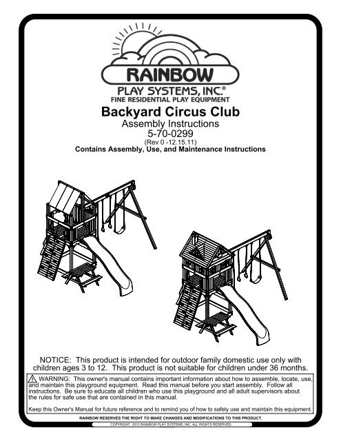
<strong>Backyard</strong> <strong>Circus</strong> <strong>Club</strong><br />
Assembly Instructions<br />
5-70-0299<br />
(Rev 0 -12.15.11)<br />
Contains Assembly, Use, and Maintenance Instructions<br />
NOTICE: This product is intended for outdoor family domestic use only with<br />
children ages 3 to 12. This product is not suitable for children under 36 months.<br />
! WARNING: This owner's manual contains important information about how to assemble, locate, use,<br />
and maintain this playground equipment. Read this manual before you start assembly. Follow all<br />
instructions. Be sure to educate all children who use this playground and all adult supervisors about<br />
the rules for safe use that are contained in this manual.<br />
Keep this Owner's Manual for future reference and to remind you of how to safely use and maintain this equipment.<br />
RAINBOW RESERVES THE RIGHT TO MAKE CHANGES AND MODIFICATIONS TO THIS PRODUCT.<br />
COPYRIGHT 2012 RAINBOW PLAY SYSTEMS, INC. ALL RIGHTS RESERVED
OWNER'S MANUAL<br />
Rainbow Play Systems, Inc.<br />
Thank you for choosing Rainbow Play Systems, Inc. For your and your<br />
children's safety, please read the instruction manual thoroughly before<br />
you start building your Rainbow Play Systems, Inc. playground.<br />
Familiarize yourself with all hardware and parts to help with building your<br />
playground.<br />
WARNING: Failure to follow the assembly, location, use, and<br />
maintenance instructions in this manual could result<br />
in serious injury to children using this playground.<br />
Rules for Safe Play..........................................................................2<br />
Choosing Location of Play System..................................................3<br />
Choosing Proper Surface Material...................................................3-4<br />
Maintenance....................................................................................4<br />
Helpful Tips.....................................................................................5<br />
Commonly Asked Questions...........................................................6<br />
Parts Identification...........................................................................7-15<br />
Hardware.........................................................................................16-19<br />
Tools Required for Assembly..........................................................19<br />
Instructions......................................................................................20-52<br />
Warranty..........................................................................................53<br />
1
Thoroughly read all Safety Instructions on pages 2-5 before beginning assembly of<br />
your playset.<br />
Welcome to RAINBOW<br />
Welcome to our family of ready-to-build residential play equipment. Ease of assembly has been pre-engineered into<br />
our product and we provide step-by-step installation instructions.<br />
To ensure safe play for your children, before building your play system, please take some time with your children and<br />
go over the Rules for safe play on your play system. Do not allow children in the area while you are assembling<br />
your play system. Many of Rainbow's components are very heavy and could seriously injure a child. Observing these<br />
rules reduces the likelihood of serious or fatal injury.<br />
After thoroughly reading the information below, locate your play site and carefully unpack parts. As you<br />
unpack your play system, keep the parts list handy and become familiar with each part before beginning assembly.<br />
Remember that a little extra time spent familiarizing yourself with the parts and the instructions before you begin will<br />
help to avoid mistakes and save you time later. Please keep these instructions for future reference.<br />
This product is recommended for children 3 to 12 years of age.<br />
Note: This product is not intended for public use. Rainbow Play Systems, Inc. does not<br />
warranty its Residential Play Equipment subject to commercial use.<br />
Safety Instructions<br />
Rules for Safe Play<br />
WARNING: Before allowing children to play on this equipment for the first time, carefully review<br />
the rules for safe play with them. Observing the following statements and warnings<br />
reduces the likelihood of a serious or fatal injury.<br />
1. IT IS RECOMMENDED that no more than 6-8 children, not exceeding a combined weight of 1,200 pounds, play on the<br />
system at one time. This product is recommended for children 3 to 12 years of age.<br />
2. CLOSE ADULT SUPERVISION is required for children of all ages.<br />
3. WARN CHILDREN TO AVOID playing or walking in front of, behind, or between moving equipment.<br />
4. WARN CHILDREN NOT TO twist swing chains or ropes, or to loop them over the top support bar since this may reduce the<br />
strength of the chain or rope.<br />
5. INSTRUCT CHILDREN NOT TO swing empty seats, trapeze bar, gliders, buoy balls or tire swings.<br />
6. INSTRUCT CHILDREN to always sit, never stand or kneel, in the center of the swing seat with their full weight.<br />
7. INSTRUCT CHILDREN NOT TO use any part of the play system in a manner other than what it is intended.<br />
8. INSTRUCT CHILDREN NOT TO get off equipment while it is in motion.<br />
9. DRESS CHILDREN APPROPRIATELY. CHILDREN SHOULD NOT wear scarves, hats with straps, helmets, jackets with<br />
draw strings, hooded jackets, poorly fitting shoes, or any other loose fitting clothing that is potentially hazardous while<br />
using equipment.<br />
10. INSTRUCT CHILDREN NOT TO play on the equipment if it is wet. Potentially slippery surfaces may cause a hazard.<br />
11. VERIFY all suspended items such as ropes and chains are secure at both ends.<br />
12. VERIFY all suspended items such as climbing ropes are tight so they cannot be looped back on themselves.<br />
13. INSTRUCT CHILDREN NOT TO attach items to the play system not specifically intended for use with the play equipment.<br />
Items such as, but not limited to, jump ropes, clotheslines, pet leashes, cables and chain may pose a strangulation hazard.<br />
14. INSTRUCT CHILDREN TO REMOVE any bike or other sports helmets before playing on the play equipment, as they may<br />
pose a possible hanging hazard. Children must be dressed appropriately.<br />
15. INSTRUCT CHILDREN there may only be one person on a swing at a time with a maximum weight of 150 pounds per swing.<br />
16. VERIFY there are no gaps between the slide bed way and the slide screws.<br />
17. INSTRUCT CHILDREN to always go down slides feet first. Never slide head first.<br />
18. INSTRUCT CHILDREN TO NEVER climb, crawl, or walk on items not intended for such use. Such types of play on top of<br />
Monkey Bars, Fort Roof, and Swing Beams greatly increase the risk of a serious or fatal fall.<br />
2
Choosing a location for your play system<br />
When selecting your play site, always keep the child's safety in mind. Here are some recommendations that should help you achieve a safe<br />
play area.<br />
1. The play system should be located on solid level ground free of objects that could cause injury such as, but not limited to, tree stumps,<br />
roots, and large rocks. Stationary components such as ladders and slides must be no less than SIX FEET (1.8 meters) from any<br />
structure or obstruction such as a fence, garage, house, tree or overhanging branches, electrical wires or clotheslines. Any swinging<br />
equipment must be a minimum distance of TWICE the height of the swing beam away from any structures or obstructions as specified<br />
above. We also recommend that you do not install your play system near a lake, river, swimming pool or other water hazards.<br />
2. If anchoring your play system, all underground utilities must be located in play zone before starting assembly of play system.<br />
3. Try to locate slide out of direct sunlight to reduce the likelihood of serious burns. A slide that faces north will receive the least direct<br />
sunlight.<br />
4. It is recommended not to place a set on sandy soil or loose fill as it may require additional anchoring in that situation.<br />
5. Do not install your play system over concrete, asphalt, packed earth, grass, carpet, or any other hard surface. A fall onto a hard surface<br />
can result in serious injury to the play system user.<br />
Set Dimensions Play Zone<br />
L 15 1/2' x W 15' x<br />
H 11'<br />
L 27 1/2' x W 30 1/2'<br />
6' min.<br />
6' min. 6' min.<br />
6' min.<br />
2x Swing<br />
Beam Height<br />
2x Swing<br />
Beam Height<br />
Choosing a surfacing material<br />
The consumer shall provide playground surfacing materials under and around residential play equipment that conforms to the<br />
recommendations of the Consumer Product Safety Commission's Outdoor Home Playground Safety Handbook publications #324. A copy<br />
of the section relating to surfacing materials is included in the installation instructions. Free copies of this handbook are available on line at<br />
www.cpsc.gov or by contacting the CPSC Publications Office in Washington D.C. 20207.<br />
The URL is http://www.cpsc.gov/cpscpub/pubs/324.pdf and the file size is 456.5KB<br />
Playground equipment should never be placed on hard surfaces such as concrete or asphalt. Do not use loose fill surfacing on top of hard<br />
surfaces such as concrete or asphalt. While grass may appear to be acceptable, it may quickly turn to hard packed earth in areas of high<br />
traffic. Shredded bark mulch, wood chips, fine sand or fine gravel are considered to be acceptable shock absorbing surfaces when installed<br />
and maintained at a sufficient depth under and around playground equipment. The U.S. Product Safety Commission (CPSC) estimates that<br />
about 100,000 playground equipment-related injuries resulting from falls to the ground surface are treated annually in U.S. hospital's<br />
emergency rooms. Injuries involving this hazard pattern tend to be the most serious of all playground injuries, and have a potential to be<br />
fatal, particularly when the injury is to the head. The surface under and around playground equipment can be a major factor in determining<br />
the injury-causing potential of a fall. It is self evident that a fall onto a shock absorbing surface is less likely to cause a serious injury than a<br />
fall onto a hard surface.<br />
The following information is intended to assist in comparing the relative shock-absorbing properties of various materials. No particular<br />
material is recommended over another. However, each material is only effective when properly maintained. Materials should be checked<br />
periodically and replenished to maintain correct depth as determined necessary for your equipment. The choice of a material depends on<br />
the type and height of your playground equipment, the availability of the material in your area, and its cost.<br />
Table 3.1 lists the maximum height from which a child would not be expected to sustain a life-threatening head injury in a fall onto four<br />
different loose-fill surfacing materials if they are installed and maintained at depths of 6, 9, and 12 inches. However, it should be recognized<br />
that all injuries due to falls cannot be prevented no matter what surfacing material is used.<br />
3
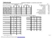
TABLE 3.1 Fall Height in Feet From Which a Life Threatening Head Injury Would Not Be Expected<br />
Type of Material 6 in. depth 9 in. depth 12 in. depth<br />
Double Shredded Bark Mulch 6 ft. 10 ft. 11 ft.<br />
Wood Chips 6 ft. 7 ft. 12 ft.<br />
Fine Sand 5 ft. 5 ft. 9 ft.<br />
Fine Gravel 6 ft. 7 ft. 10 ft.<br />
Surfacing in "compressed" depths - See CPS & ASTM for Fall Heights of equipment<br />
Equipment Fall Height 1' 2' 3' 4' 5' 6' 7' 8' 9' 10' 11' 12'<br />
Wood Chips 6" 6" 6" 6" 6" 6" 6 1/2" 7 1/2" 8 1/4" 9" 12" 13"<br />
Double Shredded Bark Mulch 6" 6" 6" 6" 7" 8" 9" 9 3/4" 10 1/2" 11 1/2" 12" 13"<br />
Engineered Wood Fibers 6" 6" 6" 7" 8 1/2" 9" 9 1/2" 10 1/4" 10 3/4" 11" 10 3/4" 12"<br />
Fine Sand 6" 6" 6 1/2" 8" 9 10" 10 1/2" 11 1/4" 12" 13 1/2" 14 3/4" 16"<br />
Coarse Sand 6" 6" 7 1/2" 9" 10 1/2" 12" 14" 16" 18" 20" 22" 24"<br />
Fine Gravel 6" 6" 6" 6 3/4" 8" 9" 10" 10 3/4" 11 1/2" 12" 13 1/4" 14 1/2"<br />
Medium Gravel 6" 6 1/4" 8" 9" 9" 12" 14" 16" 18" 20" 22" 24"<br />
Chart obtained from U.S. Consumer Product Safety Commission Handbook for Public Playground Safety<br />
NOTICE: It is recommended to use containment, such as digging out around the perimeter and/or lining the perimeter with<br />
landscape edging for surfacing materials.<br />
Installations of rubber tiles or poured-in-place surfaces (other than loose-fill materials) generally require a professional and are<br />
not "do-it-yourself" projects.<br />
When surfacing is to be used it is recommended to use Playground Surfacing Materials (other than loose-fill materials) which<br />
comply to the safety standard ASTM 1292 Standard Specification for Impact Attenuation of Surfacing Materials within the Use<br />
Zone of Playground Equipment.<br />
Maintenance of your play system<br />
To ensure safe enjoyment of your Rainbow Play System for years to come, follow these maintenance tips:<br />
1. At the beginning of each usage season and twice each month, check and tighten as needed (but do not over<br />
tighten causing the wood to crack) all nuts and bolts. Acorn nuts should be tightened to 5 foot pounds of torque.<br />
Hardware used on swinging elements should be checked at least twice a month to ensure proper fastening.<br />
2. At the beginning of each usage season and twice each month, check all coverings for bolts and sharp edges<br />
to be certain they are in place. Replace when necessary.<br />
3. Oil all metallic moving parts and grease Tire Swivel monthly during the usage period.<br />
4. Check all moving parts including swing seats, ropes, and chains for wear, rust, or other deterioration and replace<br />
as needed.<br />
5. Check all metal parts for rust. If needed, sand and repaint using a nonlead-based paint meeting the<br />
requirements of Title 16 CFR Part 1303.<br />
6. Check the S-Hooks on the chains to ensure the gap is less than .040 inches. Tighten/close as necessary.<br />
7. Remove plastic swing seats and take indoors or do not use when temperature drops below 32 Fahrenheit.<br />
Reinstall swing seats when the cold season is complete.<br />
8. Check, twice a month, the depth of loose fill protective surfacing materials to prevent compaction and to<br />
maintain appropriate depth. Rake or replace as necessary.<br />
9. When you are ready to dispose of your playset, make sure all metal, plastic and wood components are<br />
disposed of in accordance with local waste ordinances and ensure that no unreasonable hazards exist.<br />
10. On a yearly basis, we recommend that you coat your play system with a sealant or preservative. You may<br />
also want to spot sand areas before sealing. Be sure that the sealant you select is non-toxic and child safe.<br />
11. Check all wood members for deterioration and splinters. Spot sand any areas that are checking or<br />
splintering. If parts are deteriorating, replace as needed.<br />
4
Helpful Installation Hints<br />
1. Wear safety glasses to protect your eyes from flying wood chips when drilling or cutting.<br />
2. Verify that all bolts and screws are secured tightly and all acorn nuts are snug (acorn nuts should be<br />
tightened to 5 foot pounds of torque).<br />
3. DO NOT allow children to play on the play system until it is completely assembled in a proper location.<br />
4. DO NOT allow children in the area while you are assembling your play system. Many of the Rainbow Play<br />
Systems, Inc. components are very heavy and could seriously injure a child.<br />
5. After thoroughly reading all information and properly locating your play system site, carefully unpack<br />
parts. As you unpack your play system, keep the parts list handy and become familiar with each part before<br />
beginning assembly. Remember that a little extra time spent familiarizing yourself with the parts and<br />
instructions before you begin will help avoid mistakes and save you time later.<br />
6. Group both wood and non-wood parts together in accordance to each page, or Step, of this assembly<br />
manual. Doing this now will help you quickly locate parts and assemble the set with ease.<br />
7. Sort your hardware into groups of similar hardware pieces. Use a solid surface, such as the empty boxes, to<br />
ensure you do not lose any hardware.<br />
8. Before starting each Step, thoroughly read all of the instructions to ensure all information is understood. Pay<br />
special attention to the orientation of each part, details & notes, and proper usage of hardware. Each piece of<br />
hardware is required for a certain part of the assembly.<br />
9. Certain steps of the assembly are best performed on a hard flat surface to ensure proper and accurate<br />
assembly.<br />
10. All Lag Bolts must have pre-drilled holes 2" deep (as shown in Detail A). Use a 1/8" drill bit for all 1/4" and<br />
5/16" Lag Bolts and use a 1/4" drill bit for all 3/8" Lag Bolts. Lag Bolts can be difficult to put in knot holes.<br />
Pre-drilling pilot holes will help to prevent the Lag Bolts from breaking.<br />
11. All #14 Phillips Pan Head Tap Screws must have pre-drilled holes 1/2" deep. Use a 1/8" drill bit.<br />
12. Use a clamp to secure facias flush to the Uprights and use holes in facia as a guide for placing Lag Bolt Pilot<br />
Holes (as shown in Detail B).<br />
13. Verify Facias are flush with Uprights.<br />
14. Check assembly periodically to ensure the set is level and all facias are square to the uprights.<br />
15. If a gap occurs between boards when inserting Screws or Lag Bolts, back out hardware and apply pressure to<br />
the top board while reinserting hardware in the same hole.<br />
UPRIGHT<br />
PILOT<br />
HOLES<br />
WARNING<br />
Drilling, sawing, sanding or machining wood products generates wood dust,<br />
a substance known to the State of California to cause cancer. Avoid inhaling<br />
wood dust or use a dust mask or other safeguards for personal protection.<br />
California Health and Safety Code Section 25249.6<br />
DETAIL A<br />
FACIA<br />
FACES MUST<br />
BE FLUSH<br />
5<br />
DETAIL B<br />
USE FACIA AS<br />
A GUIDE FOR<br />
PRE-DRILLING<br />
HOLES
COMMONLY ASKED QUESTIONS<br />
Question: How do I know when Lag Bolts and other Fasteners are tightened properly?<br />
Answer: Lag Bolts and other Fasteners are tight when the head of the Lag Bolt and Washer<br />
are firmly compressed against the wood. If splintering occurs, that is an indication you<br />
are over tightening the Lag Bolts and other Fasteners. (Splintering is when the wood<br />
fibers fracture out from under the washers).<br />
Question: What should I do if a Lag Bolt or other Fastener lines up with a knot, or if the Lag Bolt<br />
breaks?<br />
Answer: There is extra Hardware provided with the set for this reason. Re-Drill a new hole with<br />
a 1/8" Drill Bit in a new direction to miss the obstruction.<br />
Question: What if my Play System is leaning and/or rocks?<br />
Answer: This is caused by unleveled ground under the Base and Support Wings of the Play<br />
System. It may be necessary to remove or add some soil beneath the Play System<br />
to make it level. Ground Stakes, when installed, will also provide stability.<br />
Question: What if my Play System has cracks on the wood or seems to be developing cracks?<br />
Answer: Seasonal checks, surface cracks, and knot holes are natural characteristics of all<br />
wooden play equipment. A check is a separation of the wood fibers running with the<br />
grain. This is caused by varying temperature and moisture conditions. By coating<br />
your Play System annually with a sealant or preservative, you can help protect your<br />
Play System from developing (not stopping) seasonal checks. Please remember to<br />
follow all installation instructions, including installing the play set on solid level ground.<br />
Question: What is the sticky substance that appears on the wood?<br />
Answer: The sticky substance that may appear on the wood is called pitch. It is common for<br />
the lumber to have occasional pitch seepage which does not affect the structural<br />
integrity of the part. Pitch provides the natural rot resistant characteristics of the<br />
lumber. If play surfaces or play items become overly sticky with pitch use rubbing<br />
alcohol to safely remove.<br />
Question: What accessories may be added or what modifications can be made to my Rainbow<br />
boxed kit set?<br />
Answer: Rainbow boxed kit sets are complete kits and are not modular. Play sets with<br />
unauthorized accessories or modifications will not be covered under warranty.<br />
Non-residential use of the play set voids warranty.<br />
Question: Is my child old enough to use all play items on my set?<br />
Answer: All play items on Rainbow boxed kit sets are designed<br />
for children ages 3 to 12, but it is the end users<br />
responsibility to determine suitability of use by their<br />
children for each play item.<br />
6<br />
EXAMPLE OF SEASONAL<br />
CHECKS OR SURFACE<br />
CRACKS
200<br />
207<br />
330<br />
331<br />
332<br />
333<br />
641<br />
663<br />
660<br />
406<br />
642<br />
352<br />
53<br />
54<br />
55<br />
56<br />
BACKYARD CIRCUS CLUBHOUSE PARTS LIST<br />
15@ 1 x 4 x 27 1/2" Rail Upright (3-01-0037)<br />
1@ 1 x 4 x 21" Ladder Entrapment Board (3-01-0044)<br />
1@ 1 x 4 x 32 1/2" Top Rock Wall Board (3-01-0093)<br />
6@ 1 x 4 x 32 1/2" 2 Hole Inside Rock Wall Board (3-01-0094)<br />
6@ 1 x 4 x 32 1/2" Rock Wall Board (3-01-0095)<br />
6@ 1 x 4 x 32 1/2" 2 Hole Rock Wall Board (3-01-0096)<br />
2@ 1 x 4 x 45 1/4" Short Deck Board (3-01-0156)<br />
12@ 1 x 4 x 52" Deck Board (3-01-0159)<br />
6@ 1 x 4 x 41" Table Board (3-01-0158)<br />
1@ 1 x 4 x 32 1/2" Rock Wall Board w/Rope Hole (3-01-0123)<br />
1@ 1 x 6 x 52" Deck Board (3-02-0032)<br />
1@ 2 x 4 x 61" Rock Wall Runner (3-03-0005)<br />
1@ 2 x 4 x 19" Table Runner (3-03-0008)<br />
2@ 2 x 4 x 30" Left Picnic Table Leg (3-03-0009)<br />
2@ 2 x 4 x 30" Right Picnic Table Leg (3-03-0010)<br />
2@ 2 x 4 x 18 3/4" Table Brace (3-03-0011)<br />
7
57<br />
58<br />
353<br />
427<br />
646<br />
418<br />
640<br />
226<br />
664<br />
408<br />
661<br />
644<br />
234<br />
BACKYARD CIRCUS CLUBHOUSE PARTS LIST<br />
2@ 2 x 4 x 45" Seat Support (3-03-0012)<br />
2@ 2 x 4 x 19" Table Support (3-03-0013)<br />
2@ 2 x 4 x 62 3/8" Rock Wall Leg (3-03-0021)<br />
1@ 2 x 4 x 5 1/4" Ship's Wheel<br />
Block (3-03-0059)<br />
1@ 2 x 4 x 51" Deck Runner (3-03-0066)<br />
4@ 2 x 6 x 52" 4 Hole Facia (3-04-0011)<br />
2@ 2 x 6 x 52" Main Beam (3-04-0015)<br />
4@ 5/4 x 4 x 27 1/2" Rail Upright w/Handle Holes<br />
(3-09-0003)<br />
6@ 5/4 x 4 x 13 1/8" Corner Facia<br />
(3-09-0086)<br />
2@ 5/4 x 4 x 9" Slide Block (3-09-0036)<br />
2@ 5/4 x 4 x 41" Seat Board<br />
(3-09-0073)<br />
4@ 5/4 x 4 x 52" 2 Hole Facia (3-09-0084)<br />
4@ 5/4 x 6 x 18" Ladder Step (3-10-0004)<br />
8
715<br />
662<br />
647<br />
650<br />
645<br />
639<br />
638<br />
643<br />
648<br />
222<br />
223<br />
77<br />
78<br />
2@ 5/4 x 6 x 52" 6 Hole Facia (3-10-0051)<br />
2@ 5/4 x 6 x 41" Seat Board (3-10-0030)<br />
2@ 5/4 x 6 x 52" 6 Hole Facia (3-10-0041)<br />
3@ 5/4 x 6 x 52" 4 Hole Facia (3-10-0042)<br />
1@ 5/4 x 6 x 52" Facia w/Rope Hole (3-10-0040)<br />
2@ 4 x 4 x 105" Corner Upright w/TJ Holes (1-06-0761)<br />
2@ 4 x 4 x 105" Corner Upright (1-06-0760)<br />
1@ 4 x 4 x 52" Top Joist w/Swing Holes (3-06-0039)<br />
1@ 4 x 6 x 64 9/16" Left Ladder Leg (3-07-0004)<br />
1@ 4 x 6 x 64 9/16" Right Ladder Leg (3-07-0005)<br />
2@ 4 x 4 x 104" A-Frame Leg (3-06-0003)<br />
1@ 4 x 4 x 60" A-Frame Cross Member (3-06-0004)<br />
81 82<br />
1@ 4 x 4 x 15" Upper A-Frame<br />
Bracket (3-06-0007)<br />
346<br />
BACKYARD CIRCUS CLUBHOUSE PARTS LIST<br />
2 @ 4 x 4 x 52" Center Post (3-06-0040)<br />
714 8 @ 4 x 4 x 16" Angled Brace (3-06-0062)<br />
1@ 4 x 6 x 106" 3 Position Swing Beam (3-07-0006)<br />
9<br />
1@ 4 x 4 x 15" Lower A-Frame<br />
Bracket (3-06-0008)
247<br />
2@ 1 x 4 x 17" Fan Vertical (3-01-0052)<br />
200<br />
11 @ 1 x 4 x 27 1/2" Rail Upright<br />
(3-01-0037)<br />
329<br />
363<br />
4@ 1 x 4 x 6 1/2" Chimney Trim (3-01-0092)<br />
1@ 1 x 4 x 13" Fan Vertical (3-01-0099)<br />
362<br />
2@ 1 x 4 x 8 3/4" Fan Ray (3-01-0098)<br />
364<br />
377<br />
1@ 1 x 4 x 15 5/8" Left Dormer Board<br />
1@ 1 x 4 x 3 3/8" Right Dormer<br />
(3-01-0100)<br />
Board (3-01-0113)<br />
365<br />
376<br />
1@ 1 x 4 x 13 9/16" Left Dormer Board<br />
1@ 1 x 4 x 5 7/16" Right Dormer<br />
(3-01-0101)<br />
Board (3-01-0112)<br />
366<br />
375<br />
1@ 1 x 4 x 11 9/16" Left Dormer Board<br />
(3-01-0102)<br />
1@ 1 x 4 x 7 1/2" Right Dormer<br />
Board (3-01-0111)<br />
367<br />
374<br />
1@ 1 x 4 x 9 1/2" Left Dormer Board<br />
(3-01-0103)<br />
1@ 1 x 4 x 9 1/2" Right Dormer<br />
Board (3-01-0110)<br />
368<br />
373<br />
1@ 1 x 4 x 7 1/2" Left Dormer Board<br />
1@ 1 x 4 x 11 9/16" Right Dormer<br />
(3-01-0104)<br />
Board (3-01-0109)<br />
369<br />
372<br />
1@ 1 x 4 x 5 7/16" Left Dormer Board<br />
1@ 1 x 4 x 13 9/16" Right Dormer<br />
(3-01-0105)<br />
Board (3-01-0108)<br />
370 371<br />
1@ 1 x 4 x 3 3/8" Left Dormer Board<br />
1@ 1 x 4 x 15 5/8" Right Dormer<br />
(3-01-0106)<br />
Board (3-01-0107)<br />
399<br />
401<br />
4@ 1 x 4 x 11 3/4" Fan Ray (3-01-0116)<br />
12@ 1 x 4 x 14 1/2" Window Upright<br />
(3-01-0118)<br />
402<br />
11@ 1 x 4 x 14 1/2" Cabin Upright (3-01-0119)<br />
404<br />
6@ 1 x 4 x 15 1/2" Window Board<br />
(3-01-0121)<br />
653<br />
WOOD ROOF ADD-ON PARTS LIST<br />
24@ 1 x 4 x 54 5/8" Roof Board (3-01-0157)<br />
378<br />
379<br />
1@ 1 x 6 x 18" Chimney Front (3-02-0025)<br />
1@ 1 x 6 x 12 1/8" Chimney Back<br />
(3-02-0026)<br />
416<br />
655<br />
2@ 1 x 6 x 44" Fan Horizontal (3-02-0027)<br />
2@ 1 x 6 x 44 3/4" Filler Board<br />
(3-02-0033)<br />
355<br />
1@ 2 x 4 x 26" Fan Horizontal (3-03-0050)<br />
356<br />
1@ 2 x 4 x 6" Fan Center (3-03-0051)<br />
10<br />
659<br />
1 @ 1 x 6 x 27 1/2" Rail Upright<br />
(3-02-0034)
357<br />
1@ 2 x 4 x 24 1/4" Left Dormer Support (3-03-0052)<br />
358<br />
1@ 2 x 4 x 24 1/4" Right Dormer Support (3-03-0053)<br />
359<br />
651<br />
652<br />
380<br />
409<br />
410<br />
654<br />
308<br />
382<br />
390<br />
1@ 2 x 4 x 6 5/8" Chimney Block (3-03-0054)<br />
2@ 2 x 4 x 40" Left Roof Support (3-03-0067)<br />
2@ 2 x 4 x 40" Right Roof Support (3-03-0068)<br />
2@ 5/4 x 4 x 23 1/2" Dormer Runner (3-09-0033)<br />
4@ 5/4 x 4 x 35" Roof Frame Side (3-09-0037)<br />
2@ 5/4 x 4 x 39" Roof Runner (3-09-0038)<br />
4@ 5/4 x 4 x 58 5/8" Roof Frame (3-09-0085)<br />
2@ 5/4 x 6 x 9 1/2" Peak Facia (3-10-0012)<br />
2@ 5/4 x 6 x 17 3/8" Chimney Side (3-10-0016)<br />
2@ 5/4 x 6 x 52" Angled Double Arched Facia (3-10-0018)<br />
656<br />
1@ 5/4 x 6 x 52" Double Arched Facia (3-10-0043)<br />
657<br />
WOOD ROOF ADD-ON PARTS LIST<br />
1@ 5/4 x 6 x 52" Arched Facia (3-10-0044)<br />
11<br />
412<br />
349<br />
6@ 5/4 x 4 x 15 1/2" Window Horizontal<br />
(3-09-0040)<br />
2@ 5/4 x 6 x 9" Fan Center (3-10-0013)
N20<br />
N8<br />
1@ Ship's Wheel<br />
(5-41-0021)<br />
8@ Small 90 Bracket<br />
(5-35-0089)<br />
N29<br />
14@ Bolt Cup<br />
(5-47-0043)<br />
N73<br />
N5<br />
2@ Small Bolt Cup<br />
(5-47-0035)<br />
4@ Safety Handle - Yellow<br />
(5-33-0102)<br />
4@ 90 Bracket<br />
(5-35-0090)<br />
N19<br />
N170 N171 N33<br />
1@ 45 Bracket<br />
(5-35-0094)<br />
N9<br />
2@ 90 Bracket<br />
(5-35-0095)<br />
1@ Telescope<br />
(5-41-0020)<br />
2@ T - Bracket<br />
(5-35-0087)<br />
N83<br />
1@ Plaque<br />
(5-42-0028)<br />
N38<br />
12@ Rock<br />
(5-42-0012/5-42-0021)<br />
N26 N27 N30 N31<br />
6@ Swing Hanger<br />
(5-45-0012)<br />
PARTS IDENTIFICATION<br />
6@ Spring Clip<br />
(5-47-0023)<br />
12<br />
4@ C-Link<br />
(5-47-0044)<br />
N28<br />
6@ Rebar Stake<br />
(5-47-0033)<br />
N10<br />
1@ Swing Beam<br />
Plate - Brown<br />
(5-35-0092)<br />
4@ Pear Link<br />
(5-47-0045)
N18 N14<br />
1@ Trapeze Bar - Yellow<br />
(5-40-0063)<br />
N15<br />
N6<br />
N13<br />
N12<br />
2@ Swing Seats<br />
(5-40-0034/5-40-0049)<br />
2@ Ladder Handle<br />
(5-33-0133)<br />
4@ Long Chain - Yellow<br />
(5-37-0027)<br />
2@ Short Chain - Yellow<br />
(5-37-0026)<br />
PARTS IDENTIFICATION<br />
2@ Trapeze Ring<br />
(5-40-0014)<br />
Parts Not Shown<br />
N24<br />
N264<br />
N1<br />
N17<br />
N169<br />
1@ Double Wall Wave Slide - Yellow (5-44-0139)<br />
1@ Tarp - Green/RYB (5-22-0258/0259)<br />
1@ 12' Rope (5-20-0124)<br />
1@ Half Bucket Swing (designed for children ages 3-5)<br />
1@ 4-Chain Tire Swing (optional)<br />
13
N24<br />
55<br />
54<br />
57<br />
56 662<br />
661<br />
660<br />
58<br />
418<br />
638<br />
639<br />
650<br />
715<br />
664<br />
406<br />
332<br />
333<br />
331<br />
353<br />
650<br />
N5<br />
226<br />
645<br />
664<br />
641<br />
663<br />
642<br />
330<br />
N21<br />
647<br />
644<br />
N264<br />
714<br />
200<br />
77<br />
78<br />
81<br />
82<br />
N171<br />
N170<br />
346<br />
N83<br />
N26<br />
N15<br />
N31<br />
N14<br />
N18<br />
N13<br />
N12<br />
PARTS IDENTIFICATION<br />
14
PARTS IDENTIFICATION<br />
329<br />
N171<br />
346<br />
363<br />
378<br />
654<br />
382<br />
81<br />
653<br />
356<br />
409<br />
362<br />
247<br />
308<br />
82<br />
416<br />
357<br />
399<br />
355<br />
652<br />
77<br />
654<br />
655<br />
412<br />
390<br />
349<br />
401<br />
404<br />
78<br />
647<br />
N5<br />
15<br />
200<br />
N6<br />
223<br />
N24
H7<br />
H1<br />
H30<br />
H32<br />
H34<br />
H28<br />
H17<br />
H24<br />
HARDWARE FOR ASSEMBLY<br />
H93<br />
H108<br />
H116<br />
H155<br />
H154<br />
H152<br />
H194<br />
H176<br />
H157<br />
H158<br />
H166<br />
H164<br />
H163<br />
H169<br />
H170<br />
16<br />
H11<br />
H9<br />
H3<br />
H4<br />
0<br />
1<br />
2<br />
3<br />
4<br />
5<br />
6<br />
7<br />
8<br />
9
H135 H56<br />
H50<br />
HARDWARE FOR ASSEMBLY<br />
*NOTE: Thread length may vary from what is pictured.<br />
H60<br />
17<br />
H124<br />
H184<br />
H55<br />
0<br />
1<br />
2<br />
3<br />
4<br />
5<br />
6<br />
7<br />
8<br />
9
H100<br />
HARDWARE FOR ASSEMBLY<br />
*NOTE: Thread length may vary from what is pictured.<br />
H104<br />
H146<br />
18<br />
H184<br />
H131<br />
H139<br />
0<br />
1<br />
2<br />
3<br />
4<br />
5<br />
6<br />
7<br />
8<br />
9
<strong>Backyard</strong> <strong>Circus</strong> <strong>Club</strong>house Hardware List<br />
F/N# DESCRIPTION DIMENSION QTY<br />
H1 Flat Washer 1/4" 118<br />
H3 Flat Washer 3/8" 29<br />
H4 Flat Washer 1/2" 11<br />
H7 SAE Washer 1/4" 92<br />
H9 Lock Washer 1/4" 12<br />
H11 Lock Washer 3/8" 30<br />
H17 Standard Nut 3/8" 10<br />
H24 Nylock Nut 3/8" 12<br />
H28 Acorn Nut 3/8" 22<br />
H30 Round Pallet Nut 3/8" 4<br />
H32 4 Prong T-Nut 1/4" 44<br />
H34 4 Prong T-Nut 3/8" 4<br />
H50 Carriage Bolt 3/8" x 3 1/2" 2<br />
H55 Carriage Bolt 3/8" x 6" 2<br />
H56 Carriage Bolt 3/8" x 6 1/2" 4<br />
H60 Carriage Bolt 3/8" x 8 1/2" 1<br />
H93 Lag Bolt 1/4" x 2" 6<br />
H100 Lag Bolt 1/4" x 4 1/2" 4<br />
H108 Lag Bolt 5/16" x 3" 104<br />
H116 Lag Bolt 3/8" x 3 1/2" 2<br />
H212 Hex Bolt 1/4" x 3/4" 4<br />
H146 Hex Bolt 1/4" x 2 1/4" 8<br />
H124 Hex Bolt 3/8" x 1 1/2" 2<br />
H184 Hex Bolt 3/8" x 2 1/2" 2<br />
H131 Hex Bolt 3/8" x 4 1/2" 4<br />
H135 Hex Bolt 3/8" x 6 1/2" 12<br />
H139 Hex Bolt 3/8" x 9" 1<br />
H176 Phillips Wood Screw #8 x 1" 174<br />
H194 Phillips Wood Screw #8 x 1 1/4" 258<br />
H152 Phillips Wood Screw #8 x 1 1/2" 334<br />
H154 Phillips Wood Screw #8 x 2" 32<br />
H155 Phillips Wood Screw #8 x 2 1/2" 18<br />
H158 Phillips Pan Head Tap Screw #10 x 1 1/2" 8<br />
H163 Phillips Pan Head Tap Screw #14 x 3/4" 8<br />
H164 Phillips Pan Head Tap Screw #14 x 1" 37<br />
H166 Phillips Pan Head Tap Screw #14 x 1 1/2" 8<br />
H169 Phillips Pan Head Machine Screw 1/4" x 1" 8<br />
H170 Phillips Pan Head Machine Screw 1/4" x 1 1/4" 24<br />
NOTE: EXTRA HARDWARE IS INCLUDED IN THE BAGS.<br />
NOT ALL HARDWARE WILL BE USED TO COMPLETE THE INSTALLATION.<br />
TOOLS REQUIRED FOR ASSEMBLY<br />
Tape Measure<br />
Carpenters Level<br />
Carpenters Square<br />
Rubber Mallet<br />
Claw Hammer<br />
Wood Clamp<br />
Standard or Cordless Drill<br />
with #2 & #3 Phillips Bits<br />
Electric Impact Gun or 1/4"<br />
and 3/8" Ratchet<br />
1/8" Drill Bit<br />
1/4" Drill Bit<br />
5/16" Drill Bit<br />
7/16" Drill Bit<br />
Torque Wrench<br />
Crescent Wrench<br />
19<br />
7/16" Deep Well Socket<br />
1/2" Deep Well Socket<br />
9/16" Deep Well Socket<br />
9/16" Box Wrench<br />
8' Step Ladder<br />
Safety Glasses<br />
Adult Helper
418<br />
418<br />
Step 1<br />
INSET A<br />
638<br />
DETAIL B<br />
H108<br />
1 1/4"<br />
638<br />
H1<br />
H108 H1<br />
Wall Assembly<br />
*NOTE: Pre-drill holes for all 5/16" Lag Bolts with a 1/8" drill bit.<br />
*NOTE: Do not fully tighten through bolt hardware.<br />
1. Position Corner Uprights (638) (639) on the ground. Diagram shows assembly standing up for<br />
proper assembly only. Assemble both wall assemblies separate.<br />
2. Attach Top Joist w/Swing Holes (643) to Corner Uprights (639) using 1/2" Hardware (H4) and 3/8"<br />
Hardware (H3) (H11) (H17) (H28) (H56).<br />
3. Attach bottom 4 Hole Facias (418) to Corner Uprights (638) (639) using 5/16" Hardware (H108)<br />
and 1/4" Hardware (H1). Assembly will measure 52" when properly assembled.<br />
*NOTE: 4 Hole Facias (418) must be flush with bottoms of Corner Uprights (638) (639).<br />
Holes are offset, orient as shown in Inset A.<br />
*SUGGESTION: When installing Facias, put bottom lag bolts in first and check that<br />
measurements are correct and assembly is square before inserting top lag bolts.<br />
4. Measure up 57 3/8" up on Corner Uprights (638) (639).<br />
5. Position Main Beams (640), with inside holes down, and attach using 1/4" Hardware (H1) and<br />
5/16" Hardware (H108).<br />
6. Measure up 87" on Corner Uprights (638) and attach Facia w/Rope Hole (645) using 1/4"<br />
Hardware (H1) and 5/16" Hardware (H108). Tighten all hardware at this time.<br />
638<br />
645<br />
H108<br />
640<br />
418<br />
52"<br />
639<br />
H1<br />
20<br />
B<br />
H56<br />
87"<br />
643<br />
H4<br />
418<br />
H3<br />
H17<br />
H11<br />
57 3/8"<br />
H28
Step 2<br />
1 1/4"<br />
H1<br />
H108<br />
650<br />
HOLE<br />
DOWN<br />
INSET A<br />
638<br />
639<br />
58"<br />
HOLE UP<br />
DETAIL A<br />
H108 647<br />
H1<br />
H108<br />
H108<br />
H1<br />
H1<br />
HOLE DOWN<br />
Wall Assembly<br />
*NOTE: Pre-drill holes for all 5/16" Lag Bolts with a 1/8" drill bit.<br />
*SUGGESTION: Two or three people may be required to complete this step.<br />
1. Stand both wall assemblies up and attach with 4 Hole Facias (418) using 1/4" Hardware (H1) and<br />
5/16" Hardware (H108). Ensure assembly is square. Assembly should measure<br />
52" wide when properly assembled.<br />
*NOTE: 4 Hole Facias (418) must be flush with bottoms of Corner Uprights (638) (639).<br />
Holes are offset, orient as shown in Inset A.<br />
*SUGGESTION: When installing Facias, put bottom lag bolts in first and check that<br />
measurements are correct and assembly is square before inserting top lag bolts.<br />
2. Measure up 58" on Uprights and attach 6 Hole Facia (715), with inside holes down, and 4 Hole<br />
Facias (650) using 1/4" Hardware (H1) and 5/16" Hardware (H108).<br />
*NOTE: Facias (645) (647) (650) (715) must be positioned so holes are offset.<br />
3. Attach 6 Hole Facias (647) to Uprights using 1/4" Hardware (H1) and 5/16" Hardware (H108).<br />
Top faces should be flush with tops of Top Joist (643) and Facia w/Rope Hole (645).<br />
715<br />
418<br />
21<br />
645<br />
418<br />
A<br />
715<br />
418<br />
638<br />
639<br />
643<br />
52"<br />
647<br />
H1<br />
H108
Step 3<br />
N8<br />
H164<br />
646<br />
INSET A<br />
H163<br />
H7<br />
638<br />
715<br />
663<br />
418<br />
Deck Installation<br />
1. Evenly space Deck Boards (641) (642) (663) across Main Beams (640) (as shown).<br />
2. Attach Deck Boards (641) (642) (663) to Main Beams (640) using #8 Hardware (H152).<br />
3. Center Deck Runner (646) on center pre-drilled holes and attach to Deck Boards using #8<br />
Hardware (H152).<br />
4. Center Small 90 Brackets (N8) at the ends of Deck Runner (646) and attach to Runner<br />
(646) and 6 Hole Facias (715) using 1/4" Hardware (H7) and #14 Hardware (H163) (H164).<br />
5. Measure up 25" on Corner Uprights (639) and attach 4 Hole Facia (650) using 1/4" Hardware (H1)<br />
and 5/16" Hardware (H108).<br />
641<br />
418<br />
642<br />
639<br />
22<br />
638<br />
646<br />
650<br />
715<br />
418<br />
639<br />
H152<br />
641<br />
H1<br />
640<br />
25"<br />
H108
714<br />
Step 4<br />
640<br />
*NOTE: Pre-drill holes for all 5/16" Lag Bolts with a 1/8" drill bit. Angled Braces (714) may<br />
split if not pre-drilled as instructed.<br />
1. Position Angled Braces (714) against 6 Hole Facias (715), Main Beams (640), Corner<br />
Uprights (638) (639) and flush against the bottom side of Deck Boards (not shown).<br />
2. Secure Angled Braces (714) in place using 1/4" Hardware (H1) and 5/16" Hardware (H108).<br />
715<br />
DETAIL A<br />
H1<br />
H1<br />
H108<br />
DECK BOARDS HAVE<br />
BEEN REMOVED FROM<br />
THIS VIEW FOR CLARITY<br />
OF ANGLED BRACE<br />
INSTALLATION<br />
H108<br />
714<br />
Angled Brace<br />
Installation<br />
418<br />
639<br />
638 638 639<br />
H108 H1<br />
715<br />
H1<br />
418<br />
23<br />
H108<br />
H1<br />
A<br />
H108<br />
640<br />
H108<br />
715<br />
418
Step 5<br />
664<br />
638<br />
DETAIL A<br />
664<br />
H108<br />
H1<br />
H1<br />
H108<br />
Facia Installation<br />
*NOTE: Pre-drill holes for all 5/16" Lag Bolts with a 1/8" drill bit.<br />
1. Position 2 Hole Facia (644) on Top Joist (643) side of Corner Uprights (639) and attach using 1/4"<br />
Hardware (H1) and 5/16" Hardware (H108).<br />
2. Position Corner Facias (664) (in locations shown) on top of 6 Hole Facias (715) and 4 Hole<br />
Facia (650) and attach to Corner Uprights (638) (639) using 1/4" Hardware (H1) and 5/16"<br />
Hardware (H108).<br />
638<br />
639<br />
643<br />
639<br />
664<br />
A<br />
638<br />
664 644<br />
650<br />
24<br />
715<br />
664<br />
H1<br />
H108
Step 6<br />
H169<br />
H32<br />
Safety Handle<br />
Installation<br />
1. Lay Rail Uprights w/Handle Holes (226) on a flat surface. Install 1/4" Hardware (H32) into<br />
pre-drilled holes (as shown). A small hammer or mallet may be used if needed.<br />
2. Flip Rail Uprights w/Handle Holes (226) and attach Safety Handles (N5) (as shown) using<br />
1/4" Hardware (H169) and previously installed 1/4" Hardware (H32).<br />
226<br />
25<br />
H169<br />
H32<br />
N5<br />
226
Step 7<br />
*NOTE: Install Rail Uprights as shown below if assembling the <strong>Club</strong>house without a Cabin<br />
package.<br />
1. Attach Rail Uprights w/Handle Holes (226) to 6 Hole Facia (647), Facia w/Rope Hole (645), and<br />
Corner Facias (664) using #8 Hardware (H152) (as shown). Flush outside faces (as shown<br />
in Detail A).<br />
2. On sides A, B, and C evenly space Rail Uprights (200) (as shown) and attach to 6 Hole Facias<br />
(647), Corner Facias (664), and Facia w/Rope Hole (645) using #8 Hardware (H194).<br />
3. Attach Rail Uprights (200) to Top Joist (643) and 2 Hole Facia (644) approximately 2 13/16 apart<br />
(as shown) using #8 Hardware (H194).<br />
645<br />
647<br />
200<br />
226<br />
226<br />
A<br />
H152<br />
B<br />
664<br />
200<br />
226<br />
Rail Installation<br />
(for sets without<br />
Cabin Package)<br />
H194<br />
664<br />
26<br />
643<br />
664<br />
FACES<br />
FLUSH<br />
2 13/16"<br />
200<br />
DETAIL A<br />
H194<br />
C<br />
664<br />
226<br />
200<br />
647<br />
644<br />
200
Step 7b<br />
*NOTE: Install Rail Uprights as shown below if installing Cabin package.<br />
1. Attach Rail Uprights w/Handle Holes (226) to 6 Hole Facia (647), Facia w/Rope Hole (645), and<br />
Corner Facias (664) using #8 Hardware (H152) (as shown). Flush outside faces (as shown<br />
in Detail A).<br />
2. On sides A, B, and C evenly space Rail Uprights (200) (as shown) and attach to 6 Hole Facias<br />
(647), Corner Facias (664), and Facia w/Rope Hole (645) using #8 Hardware (H194).<br />
3. Evenly space and attach Rail Uprights (200) (659) to Top Joist (643) and 2 Hole Facia (644)<br />
(as shown) using #8 Hardware (H194).<br />
645<br />
647<br />
200<br />
226<br />
226<br />
A<br />
H152<br />
B<br />
664<br />
200<br />
226<br />
Rail Installation<br />
(for sets with Cabin<br />
Package)<br />
H194<br />
664<br />
26b<br />
643<br />
664<br />
FACES<br />
FLUSH<br />
659<br />
H194<br />
C<br />
DETAIL A<br />
200<br />
664<br />
226<br />
200<br />
647<br />
644<br />
200
Step 8<br />
H32<br />
N21<br />
222<br />
H7<br />
H170<br />
H34<br />
Rock Wall & Step<br />
Ladder T-Nut Installation<br />
*NOTE: Do not fully tighten 3/8" Hardware (H184) (H124) in this step.<br />
1. Position Step Ladder Legs (222) (223) and Rock Wall Legs (353) as shown and install 3/8"<br />
Hardware (H34) into pre-drilled holes. A small hammer or mallet may be used to gently tap<br />
hardware flush with the wood.<br />
2. Install 1/4" Hardware (H32) into pre-drilled holes of Rock Wall Boards (331) (333). Only two Rock<br />
Wall Boards are shown, be sure to complete this step for all Rock Wall Boards (331) (333).<br />
3. Attach 90 Bracket (N9) to Step Ladder Legs (222) (223) using 3/8" Hardware (H11) (H34) (H184).<br />
4. Attach 90 Bracket (N9) to Rock Wall Legs (353) using 3/8" Hardware (H11) (H34) (H124).<br />
5. Attach Rocks (N21) to Rock Wall Boards (331) (333) using 1/4" Hardware (H7) (H170).<br />
*NOTE: Four 1/4" SAE Washers (H7) must be used per Rock installation (as shown).<br />
H11<br />
H184<br />
N9 H34<br />
H32<br />
27<br />
223<br />
N9<br />
H34<br />
N21<br />
H7<br />
H170<br />
333<br />
353<br />
N9<br />
H34<br />
353<br />
N9<br />
H11<br />
H124<br />
331
Step 9<br />
17"<br />
11/16"<br />
223<br />
222<br />
N6<br />
234<br />
H155<br />
N6<br />
Step Ladder<br />
Assembly<br />
*NOTE: To ease assembly, assemble Ladder on a flat surface. Place ends of ladder legs<br />
on boards to allow for centering and attaching Ladder Steps (234) (as shown) in<br />
INSET A.<br />
1. Flush surfaces of Left Step Ladder Leg (222) and Right Step Ladder Leg (223).<br />
2. Center Steps (234) on Ladder Legs (222) (223) (as shown in INSET A) and attach using #8<br />
Hardware (H155).<br />
3. Measure down approximately 1 1/4" from the angled edge of Ladder legs (222) (223) (as shown in<br />
INSET A) and attach Ladder Entrapment Board (207) using #8 Hardware (H152).<br />
4. Measure up 17" from the bottom of Ladder Legs (222) (223) (as shown in INSET A) and attach<br />
Ladder Handles (N6) using #14 Hardware (H166).<br />
INSET A<br />
H166<br />
28<br />
N6<br />
H152<br />
207<br />
N9<br />
207 H152<br />
1 1/4"<br />
N9
Step 10<br />
*NOTE: To ease assembly, assemble Ladder on a flat surface.<br />
1. Position Rock Wall Legs (353) (as shown) on a flat surface. Flush the top end of the Rock Wall<br />
Legs (as shown) in Inset A and Detail A.<br />
2. Position Top Rock Wall Board (330) in place (as shown) and attach using #8 Hardware (H152).<br />
3. Position top two Inside 2 Hole Rock Wall Boards (331) in the locations shown but do not attach at<br />
this time (Boards will not be attached until Step 11).<br />
4. Position Rock Wall Board (332) in location directly below unattached boards and attach using #8<br />
Hardware (H152).<br />
5. Place the rest of the Rock Wall Boards (331) (332) (333) (406) in the proper locations (as shown in<br />
Inset A) but only attach the bottom Rock Wall Board (352) (as shown) using #8 Hardware (H152).<br />
6. Ensure assembly is square and finish attaching all the rock wall boards using #8 Hardware<br />
(H152).<br />
7. Position Rock Wall Runner (352) against the bottom of Top Rock Wall Board (330) and center on<br />
Rock Wall Board holes (as shown in Inset A) and attach to Rock Wall Boards using #8 Hardware<br />
(H152).<br />
H152<br />
332 333 333<br />
DETAIL A<br />
352<br />
30 1/2"<br />
BOTTOM<br />
406<br />
406<br />
FACES<br />
FLUSH<br />
332<br />
353<br />
Rock Wall Assembly<br />
POSITION BOARD<br />
AND ATTACH<br />
POSITION BOARDS<br />
AS SHOWN BUT<br />
DO NOT ATTACH<br />
INSET A<br />
POSITION BOARD<br />
AND ATTACH<br />
333 332 331 332 333 332 331 332 333 332 331 330<br />
29<br />
332<br />
TOP<br />
332<br />
H152<br />
330<br />
1"<br />
13 5/8"<br />
331<br />
32 1/2"
Step 11<br />
715<br />
N9<br />
H7<br />
H164<br />
Rock Wall Assembly<br />
1. Center Ladder Assembly on 6 Hole Facia (715) and attach using 1/4" Hardware (H7) and #14<br />
Hardware (H164).<br />
2. Center Rock Wall Assembly on 4 Hole Facia (650) and attach using 1/4" Hardware (H7) and #14<br />
Hardware (H164).<br />
3. Tighten 3/8" Hardware in 90 Brackets (N9).<br />
4. Install Inside 2 Hole Rock Wall Boards (331) using #8 Hardware (H152).<br />
5. Thread Rope (N1) through Rock Wall Board w/Rope Hole (406) and tie a double knot on the back<br />
side of the rock wall board.<br />
6. Tie three single knots evenly throughout the rope.<br />
7. Thread rope through Facia w/Rope Hole (645) and tie a double knot on the backside of Facia<br />
(645).<br />
645<br />
A<br />
650<br />
H164<br />
30<br />
H7<br />
H164<br />
353<br />
DETAIL A<br />
H7<br />
N9<br />
N38<br />
N1<br />
H152<br />
331<br />
H152<br />
SINGLE KNOTS<br />
406<br />
DOUBLE KNOT<br />
ON BACKSIDE<br />
715<br />
N9
Step 12<br />
715<br />
408<br />
Slide Installation<br />
*NOTE: Use an 1/8" drill bit to drill holes 1/2" deep for #14 Hardware.<br />
1. Center Double Wall Wave Slide (N24) in the opening and position approximately 4" back from the<br />
front face of 6 Hole Facia (715).<br />
2. Position Slide Blocks (408) under the deck boards and attach Slide (N24) through the deck boards,<br />
into Slide Blocks (408) using 1/4" Hardware (H7) and #14 Hardware (H166).<br />
3. Center Small 90 Brackets (N8) behind each Rail Upright w/Handle Holes (226) and the two Rail<br />
Uprights (200) that create the slide opening. Attach to deck and rails using 1/4" Hardware (H7) and<br />
#14 Hardware (H163) (H164) (as shown in INSET A).<br />
200<br />
H166<br />
H7<br />
31<br />
226<br />
200<br />
641<br />
N8<br />
INSET A<br />
H163<br />
N24<br />
H7<br />
H164<br />
H7
Step 13<br />
N13<br />
N31<br />
N15<br />
N17<br />
Swing Assembly<br />
*NOTE: Half-Bucket Swing (N17) is intended for use by children ages 3 to 5, under adult<br />
supervision.<br />
1. Open C-Links (N30) and Pear Links (N31).<br />
*NOTE: When closing C-Links and Pear Links, securely tighten using a crescent wrench.<br />
2. Attach two Long Chains (N13) to each Swing Seat (N15) and Half-Bucket Swing (N17) using Pear<br />
Links (N31) and C-Links (N30) (as shown in Inset A).<br />
3. Attach two Short Chains (N12) to Trapeze Bar (N18) using C-Links (N30) (as shown in Inset A).<br />
4. Attach Trapeze Rings (N14) to Trapeze Bar (N18) by connecting C-Links (N30) to both the Trapeze<br />
Bar (N18) and Trapeze Rings (N14) (as shown in Inset B).<br />
*NOTE: When completed, swing assemblies should look as shown in Inset B.<br />
5. Securely close all C-Links (N30) and Pear Links (N31) by tightening with a crescent wrench.<br />
N13<br />
N30<br />
INSET A<br />
INSET B<br />
32<br />
N12<br />
N30<br />
N30<br />
N14<br />
N18
Step 14<br />
H56<br />
H4<br />
N29<br />
N10<br />
H11<br />
H3<br />
H17<br />
H28<br />
H139<br />
77<br />
H3<br />
N170<br />
H135<br />
N29<br />
N26<br />
H3<br />
H24 H11<br />
H28<br />
H3<br />
H116<br />
A-Frame Assembly &<br />
Swing Hanger Installation<br />
*NOTE: It is possible to modify your 3 Position Swing Beam to a 2 Position Swing Beam for<br />
use in small yards. See Step 31, page 51 for instructions on how to modify the 3<br />
Position Swing Beam to a 2 Position Swing Beam. Proceed with the following steps<br />
after making the modifications.<br />
1. Attach Swing Hangers (N26) to Swing Beam (346) using 3/8" Hardware (H3) (H11) (H24) (H28)<br />
(H135) and 3/8" Bolt Cup (N29).<br />
*SUGGESTION: Use a locking pliers to hold on to Hex Head Bolts (H135).<br />
2. Position Plaque (N83) in the approximate position shown and attach to Swing Beam using #10<br />
Hardware (H157) or (H158) (as shown).<br />
3. Attach Swing Beam Plate (N10) to Swing Beam (346) using 3/8" Bolt Cup (N29), 3/8" Hardware<br />
(H3) (H11) (H17) (H28) (H56), and 1/2" Hardware (H4) (as shown).<br />
*NOTE: Do not fully tighten hardware at this time.<br />
4. Attach Upper A-Frame Block (81) and Lower A-Frame Block (82) (as shown) using 3/8" Hardware<br />
(H3) (H116).<br />
5. Attach A-Frame Legs (77) to A-Frame Block assembly using 45 Bracket (N170) and 3/8" Hardware<br />
(H139) (H3) (H11) (H17).<br />
*NOTE: Do not tighten hardware completely at this time.<br />
6. Lay assembly on the ground with A-Frame Legs (77) pointing in opposite directions.<br />
N83<br />
H158<br />
H157<br />
81<br />
33<br />
82<br />
H3<br />
H11<br />
346<br />
H17<br />
77
Step 15<br />
*NOTE: Pre-drill holes for all Lag Bolts with the appropriate drill bit.<br />
1. On the ground, place Swing Beam (346) on top of Swing Beam Block (81). Align pre-drilled hole and<br />
attach through 45 Bracket (N170) using Bolt Cup (N29), 1/2" Hardware (H4), and 3/8" Hardware<br />
(H56) (H3) (H11) (H17).<br />
2. Make sure Swing Beam (346) is centered on the Swing Beam Block (81). Position 90 Brackets<br />
(N171) on Swing Beam Block (81), up against the Swing Beam (346), and attach using Bolt Cups<br />
(N73), #14 Hardware (H164), 1/4" Hardware (H1) (H100) and 5/16" Hardware (H108) (as shown in<br />
Inset B).<br />
3. Lift Swing Beam assembly into position on top of the Top Joist (643) and attach through Swing Beam<br />
(346) and Swing Beam Plate (N10) using 1/2" Hardware (H4) and 3/8" Hardware (H50) (H60) (H3)<br />
(H11) (H17) (as shown in Inset A).<br />
*NOTE: For ease of installation, insert Carriage Bolt (H60) through the Swing Beam (346), and<br />
then insert Carriage Bolts (H50). Do not tighten hardware at this time.<br />
4. Lift Swing Beam assembly up until A-Frame Legs hold Swing Beam in a level position.<br />
*CAUTION: Legs will close inward as Swing Beam is lifted up into position.<br />
*SUGGESTION: Use at least two people to lift Swing Beam assembly.<br />
*CAUTION: Legs are very unstable until Cross Member (78) is installed.<br />
5. Tighten Hex Head Bolt (H139) that goes through A-Frame Legs (77) and A-Frame Block assembly<br />
and attach 3/8" Hardware (H28). Tighten all hardware that goes through Swing Beam Plate (N10) at<br />
this time.<br />
6. Hold A-Frame Cross Member (78) in a level position against A-Frame Legs (77) so holes are centered<br />
on A-Frame Legs, and drill through A-Frame Legs using a 7/16" drill bit. Attach Cross Member using<br />
3/8" Hardware (H55) (H3) (H11) (H17) and 1/2" Hardware (H4).<br />
7. Attach A-Frame Legs (77) to A-Frame Blocks using 1/4" Hardware (H1) (H100).<br />
8. Place 3/8" Acorn Nuts (H28) on all Hardware that goes through Swing Beam Plate (N10), A-Frame<br />
Cross Member (78) and 45 Bracket (N170) after all Hardware is tightened.<br />
9. Attach Spring Clips (N27) to Swing Hangers (N26).<br />
10. Attach Swing Options to Spring Clips (N27).<br />
Swing Beam<br />
Installation<br />
*NOTE: There must be no less than 8" from the ground to the bottom of Sling Swing, Tire<br />
Swing and Half Bucket Swing when properly installed.<br />
*NOTE: Only ONE Swing Option in each opening on the Swing Beam.<br />
*NOTE: If installing 4 Chain Tire Swing see Step 30, page 50 for assembly instructions.<br />
34<br />
Continued on next page:
Step 15<br />
Continued from previous page:<br />
N10<br />
643<br />
H3<br />
H11<br />
H17<br />
H60<br />
H28<br />
INSET A<br />
643<br />
H4 H50<br />
N26<br />
N27<br />
H4<br />
346<br />
H55 H4<br />
Swing Beam<br />
Installation<br />
N170<br />
H11<br />
346<br />
H3<br />
H28<br />
77<br />
H17<br />
35<br />
H164<br />
H108<br />
H3<br />
H11<br />
H56<br />
H4<br />
N29<br />
H1<br />
H28 H17<br />
78<br />
INSET B<br />
81<br />
82<br />
346<br />
H1 H100<br />
H28<br />
77<br />
H100<br />
N73<br />
H164<br />
N171<br />
82<br />
81<br />
H4 H55
Step 16<br />
SHIP'S WHEEL<br />
HARDWARE<br />
N20<br />
N20<br />
H155<br />
Ship's Wheel &<br />
Telescope Installation<br />
*NOTE: Do not over-tighten Hardware. Ship's Wheel (N20) and Telescope Base<br />
(N19) should rotate freely.<br />
*NOTE: Pre-drill holes for all Lag Bolts with 1/8" drill bit.<br />
1. Position Ship's Wheel Block (427) against the end of Swing Beam (346) and attach using #8<br />
Hardware (H155).<br />
2. Center Ship's Wheel (N20) on Ship's Wheel Block (427) and attach using Hardware provided in<br />
Ship's Wheel Bag. Snap cap into place.<br />
3. Center Base of Telescope (N19) on Top Joist (643) and attach using Hardware provided in<br />
Telescope Bag. Snap Telescope (N19) into base.<br />
643<br />
36<br />
TELESCOPE<br />
HARDWARE<br />
427<br />
N19<br />
N19<br />
346
Step 17<br />
648<br />
INSET A<br />
H108<br />
638<br />
H1<br />
647<br />
N33<br />
647<br />
BOTTOMS<br />
FLUSH<br />
644<br />
H164<br />
648<br />
H7<br />
H108<br />
H1<br />
Tarp Installation<br />
*NOTE: If installing Wood Roof option skip to Step 19, page 39.<br />
*NOTE: Pre-drill holes for all 5/16" Lag Bolts with 1/8" drill bit.<br />
1. Line up the larger center hole on T-Brackets (N33) with the top pre-drilled hole on 6 Hole Facia<br />
(647) and attach 6 Hole Facia (647), T-Bracket (N33), and Center Post (648) together using 1/4"<br />
Hardware (H1) and 5/16" Hardware (H108). Center Posts and 6 Hole Facias should be flush on<br />
the bottom (as shown in Inset A).<br />
2. Use a level and square to ensure T-Brackets (N33) and Center Posts (648) are square with 6 Hole<br />
Facias (647) and secure T-Brackets (N33) and Center Posts (648) in place using 1/4" Hardware<br />
(H7) and #14 Hardware (H164).<br />
3. Finish attaching Center Posts (648) to 6 Hole Facias (647) using 1/4" Hardware (H1) and 5/16"<br />
Hardware (H108) through the bottom hole of the 6 Hole Facias (647).<br />
4. Position 2 Hole Facias (644) on Corner Uprights (638) (639) and Center Posts (648) and attach<br />
using 1/4" Hardware (H1) and 5/16" Hardware (H108).<br />
H108<br />
H1<br />
N33<br />
638<br />
639<br />
644<br />
37<br />
H1<br />
H108<br />
N33<br />
H7<br />
648<br />
H164<br />
644<br />
H108<br />
H1<br />
639<br />
647
Step 18<br />
644<br />
INSET A<br />
644<br />
H182<br />
N264<br />
Tarp Installation<br />
1. Evenly spread Tarp (N264) over the top of the 2 Hole Facia (644) (as shown). Female ends of the<br />
tarp snaps should face in towards each other when the tarp is freely hanging.<br />
2. Wrap Tarp (N264) around the bottom side of 2 Hole Facias (644). Starting with the middle tarp<br />
snap, work your way out gently tapping each tarp snap to leave an indentation in the wood.<br />
3. Install Snap Screws (H182) in the center of the indentations.<br />
*NOTE: Snap Screws (H182) are rolled up in the Tarp.<br />
4. Snap the Tarp (N264) to the Snap Screws (H182).<br />
5. Repeat parts 2, 3, and 4 for the other side. Ensure Tarp (N264) is pulled tight when marking Snap<br />
Screw (H182) locations.<br />
38<br />
644<br />
N264<br />
644
Step 19<br />
H131<br />
H11<br />
638<br />
639<br />
H30<br />
H3<br />
651<br />
DETAIL A<br />
308<br />
647<br />
H30<br />
639<br />
651<br />
H154<br />
FLUSH<br />
FACES<br />
652<br />
Wood Roof<br />
Installation<br />
*SUGGESTION: Have a helper hold Roof Supports (651) (652) in place.<br />
1. Install 3/8" Hardware (H30) into pre-drilled holes of Corner Posts (638) (639) (as shown) by gently<br />
tapping with a hammer until flush with face of wood.<br />
2. Position and attach Left and Right Roof Supports (651) (652) (as shown) using 3/8" Hardware (H3)<br />
(H11) (H30) (H131). Do not fully tighten hardware at this time.<br />
3. Flush faces of Roof Supports (651) (652) and Peak Facias (308) (as shown in Detail B) and attach<br />
Peak Facias using #8 Hardware (H154).<br />
*NOTE: Tighten 3/8" Hardware (H131) at this time.<br />
4. Insert 1/4" Hardware (H32) in extra holes in 6 Hole Facias (647) and attach using 1/4" Hardware<br />
(H1) (H9) (H212).<br />
FLUSH<br />
FACES<br />
652<br />
39<br />
H154<br />
638<br />
H32<br />
H9<br />
H1<br />
H30<br />
651<br />
DETAIL B<br />
308<br />
H212<br />
308<br />
651<br />
H3<br />
652<br />
H11<br />
H131<br />
639<br />
647<br />
FLUSH<br />
FACES
Step 20<br />
653<br />
654<br />
651<br />
NO GAP<br />
H152<br />
INSET A<br />
35"<br />
654<br />
653<br />
654<br />
308<br />
652<br />
H152 H176 H152<br />
410<br />
Wood Roof<br />
Installation<br />
*NOTE: Holes in Roof Frame (654) boards are offset. Position boards correctly as shown<br />
below.<br />
1. Center top Roof Frame (654) boards on Roof Supports (651) (652) and attach using #8 Hardware<br />
(H152) (as shown in Insets A & B). Top Roof Frame (654) boards should overhang Peak Facia<br />
(308) approximately 1 1/8". Roof Frames (654) should form a peak without gaps between boards<br />
(as shown in INSET A).<br />
2. Measure down 35" from the bottom of the Roof Frames (654) on BOTH Roof Supports and attach<br />
bottom Roof Frames (654) to Roof Supports using #8 Hardware (H152).<br />
3. Position Roof Boards (653) on Roof Supports (651) (652) between the top and bottom Roof Frame<br />
(654) boards. Center Roof Boards (653) on Roof Supports (651) (652), space evenly, and attach<br />
using #8 Hardware (H152).<br />
4. After attaching the first 5-6 Roof Boards (653) (on each side of roof), center and attach Roof<br />
Runner (410) to Roof Boards (653) using #8 Hardware (H176), and to Roof Frames (654) using #8<br />
Hardware (H152).<br />
5. Finish attaching the rest of Roof Boards (653) to Roof Supports (651) (652) using #8 Hardware<br />
(H152) and to Roof Runner (410) using #8 Hardware (H176).<br />
40<br />
308<br />
H152<br />
INSET B<br />
651<br />
654<br />
654<br />
308<br />
1 1/4"<br />
1 1/8"<br />
652
Step 21<br />
1. Position Roof Frame Sides (409) in locations shown and attach to Roof Boards (653) using #8<br />
Hardware (H152). When properly installed, outside faces of Roof Frames (654) and Roof Frame<br />
Sides (409) should be flush.<br />
2. Repeat for other side of Roof.<br />
409<br />
654<br />
H152<br />
654<br />
Wood Roof<br />
Installation<br />
653<br />
41<br />
654<br />
409<br />
409<br />
410<br />
DETAIL A<br />
A<br />
FACES<br />
FLUSH<br />
409
Step 22<br />
H108<br />
H1<br />
656<br />
Cabin Facia<br />
Installation<br />
1. Position Angled Double Arched Facias (390) up against the bottom of Roof Supports (651) (652)<br />
and attach using 1/4" Hardware (H1) and 5/16" Hardware (H108). Angled Double Arched Facias<br />
(390) and Roof Supports (651) (652) should have minimal gaps between surfaces.<br />
2. Position Arched Facia (657) and Double Arched Facia (656) (in locations shown) with bottoms<br />
flush to the bottoms of Angled Double Arched Facias (390) (as shown in Inset A) and attach to<br />
Uprights using 1/4" Hardware (H1) and 5/16" Hardware (H108).<br />
42<br />
390<br />
390<br />
BOTTOM<br />
FACES<br />
FLUSH<br />
651<br />
657<br />
INSET A<br />
652<br />
H1<br />
656<br />
H108<br />
NO<br />
GAP
Step 23<br />
404<br />
H194<br />
401<br />
412<br />
404<br />
A<br />
INSET A<br />
16 1/4"<br />
402<br />
H194<br />
H194<br />
401<br />
11 1/4"<br />
402<br />
200<br />
Cabin Rail<br />
Installation<br />
*NOTE: All window openings must have Window Uprights (401) on each side with holes<br />
facing in (as shown in Inset A).<br />
*NOTE: Window Uprights (401) and Cabin Uprights (402) should rest on top of or flush with<br />
tops of Rail Uprights (200) (226).<br />
1. Using the measurements provided in the diagrams below, install Window Uprights (401) and Cabin<br />
Uprights (402) in locations shown using #8 Hardware (H194).<br />
2. Center Window Horizontals (412) vertically and horizontally on Window Uprights (401) pre-drilled<br />
holes and attach through the Window Uprights (401) using #8 Hardware (H194) (as shown in<br />
Inset A).<br />
3. Center Window Vertical (404) on pre-drilled hole of Window Horizontal (412) and attach through<br />
Window Horizontal (412) using #8 Hardware (H194).<br />
4. Secure the top and bottom of Window Verticals (404) in place by attaching to Facias using #8<br />
Hardware (H194).<br />
412<br />
390<br />
401<br />
43<br />
401<br />
402<br />
16 1/4"<br />
H194<br />
11 1/4"<br />
402
Step 24<br />
H194<br />
655<br />
INSET A<br />
416<br />
651<br />
399<br />
247<br />
247<br />
638<br />
399<br />
Fan Installation<br />
1. Position Filler Boards (655) in between Uprights (638) (639) and with the top edge approximately<br />
2 1/4" up from tops of Uprights (638) (639) and attach to Roof Supports (651) (652) using #8<br />
Hardware (H152).<br />
2. On a flat surface position Fan Horizontal (416), Fan Vertical (247), and Fan Center (349) (as<br />
shown) and attach using #8 Hardware (H194).<br />
3. Position Fan Rays (399) (as shown in Inset A & B) and attach to Fan Center (349) using #8<br />
Hardware (H194).<br />
4. Position Fan assembly directly on top of Filler Boards (655) and attach to Roof Supports (651)<br />
(652) using #8 Hardware (H152).<br />
652<br />
652<br />
416<br />
44<br />
349<br />
H152<br />
399<br />
3"<br />
247<br />
H152<br />
INSET B<br />
399<br />
247<br />
651<br />
416<br />
655<br />
45°<br />
17 1/2"<br />
2 1/4"<br />
639
Step 25<br />
358<br />
364<br />
365<br />
366<br />
367<br />
368<br />
369<br />
370<br />
371<br />
362<br />
363<br />
357<br />
355<br />
INSET A<br />
H152<br />
H154<br />
355<br />
Dormer Assembly<br />
1. On a flat surface arrange Right Dormer Support (358), Left Dormer Support (357), and Fan<br />
Horizontal (355) (as shown in Inset A & B) and attach using #8 Hardware (H154).<br />
2. Position Fan Vertical (363) and Fan Rays (362) and Fan Center (356) (as shown in Inset A & B)<br />
and attach using #8 Hardware (H152).<br />
3. Attach top two Roof Boards (364) (371) to Dormer Supports (357) (358) using #8 Hardware<br />
(H152). The top two Roof Boards should not have gaps at the peak.<br />
4. Continue attaching all Roof Boards to Dormer Supports (357) (358) using #8 Hardware (H152).<br />
5. Position Dormer Runners (380) (as shown in lower right diagram) and attach to Roof Boards using<br />
#8 Hardware (H176) and to Dormer Supports (357) (358) using #8 Hardware (H154). When<br />
Dormer Runners (380) are properly installed, they should measure approximately 3/4" in from the<br />
farthest point on the Dormer Boards.<br />
H152<br />
H152<br />
357<br />
355<br />
15/16"<br />
358<br />
45<br />
377<br />
376<br />
362<br />
375<br />
357<br />
3/4"<br />
H152<br />
374<br />
373<br />
356<br />
372<br />
INSET B<br />
371<br />
H154<br />
363<br />
358<br />
45°<br />
7 7/8"<br />
H152<br />
3/4"<br />
362<br />
364<br />
H176<br />
380<br />
H154
Step 26<br />
INSET A<br />
H152<br />
Dormer Installation<br />
1. Position Dormer assembly on roof. Dormer assembly should be centered horizontally and Dormer<br />
Supports (357) (358) should be flush with bottom edge of the third Roof Board (653).<br />
2. Attach Dormer assembly to the roof through Roof Boards (653), into Dormer Runners (380) using<br />
#8 Hardware (H152).<br />
357<br />
46<br />
380<br />
INSET B<br />
653<br />
358<br />
653
Step 27<br />
H154<br />
H152<br />
379<br />
H194<br />
INSET A<br />
378<br />
329<br />
653<br />
359<br />
382<br />
11"<br />
Chimney Installation<br />
1. On a flat surface, stand Chimney Sides (382), Chimney Back (379), and Chimney Front (378) on<br />
end (as shown) and attach using #8 Hardware (H152). Angled faces of Chimney parts should be<br />
flush.<br />
2. Center Chimney Trim (329) pieces on Chimney Sides (382) and attach using #8 Hardware (H194).<br />
3. Center Chimney Trim (329) pieces on Chimney Back (379) and Chimney Front (378) and attach<br />
using #8 Hardware (H194).<br />
4. Place Chimney Block (359) flush with angled faces of Chimney Sides (382) and attach through<br />
Chimney Sides (382) using #8 Hardware (H154).<br />
5. Position Chimney assembly on roof in desired location and attach through the underside of Roof<br />
Boards (653) into Chimney Block (359) using #8 Hardware (H152).<br />
H154<br />
H194<br />
47<br />
653<br />
INSET B<br />
H152
Step 28<br />
H146<br />
55<br />
H146<br />
H1<br />
H9<br />
H1<br />
H9<br />
H1<br />
57<br />
58<br />
54<br />
Picnic Table<br />
Assembly<br />
1. Place Left Table Legs (54), Right Table Legs (55) and Seat Supports (57) on a hard surface and<br />
pound in T-Nuts (H32) with a hammer (as shown in Inset A).<br />
*NOTE: Counter-sunk holes on Table Legs (54) (55) must be facing down.<br />
2. Line up holes on Left Table Legs (54), Right Table Legs (55), Seat Supports (57) and Table Support<br />
(58) (as shown) and attach using 1/4" Hardware (H1) (H9) (H146) (H32).<br />
57<br />
54<br />
57<br />
48<br />
H1<br />
H9<br />
55<br />
55<br />
H146<br />
54<br />
58<br />
55<br />
54<br />
H1<br />
H9<br />
H146<br />
H32<br />
H32<br />
INSET A<br />
H32
Step 29<br />
662<br />
661<br />
57<br />
660<br />
58<br />
H154<br />
53<br />
H154<br />
56<br />
H154<br />
H152<br />
55 54<br />
Picnic Table<br />
Assembly<br />
1. Stand Leg assemblies up and center Seat Boards (661) (662) on Seat Supports (57). Seat Boards<br />
(661) (662) should overhang 5 7/8" on the ends and the edges of Seat Boards (662) and Seat<br />
Supports (57) must be flush (as shown). Attach Seat Boards (661) (662) to Seat Supports (57)<br />
using #8 Hardware (H154).<br />
2. Center Table Boards (660) on Table Supports (58) and attach using #8 Hardware (H152). Table<br />
should not have gaps between Table Boards (660) when properly assembled.<br />
*NOTE: Assembling Picnic Table on a hard level surface will help ensuring that the<br />
Table is square.<br />
3. Insert Screws (H154) into holes on Left Table Legs (54) and Right Table Legs (55) and attach to<br />
Table Supports (58) using #8 Hardware (H154).<br />
4. Center and attach Table Runner (53) on the bottom side of Table Boards (660) using #8 Hardware<br />
(H152).<br />
5. Position Table Braces (56) so they are centered on Seat Supports (57) and Table Runner (53) and<br />
attach using #8 Hardware (H152) (H154). #8 x 1 1/2" Hardware (H152) must go through Table<br />
Braces (56) and into Seat Supports (57).<br />
49<br />
H152<br />
56<br />
57<br />
H154<br />
55
Step 30<br />
N12<br />
N30<br />
N12<br />
12"<br />
INSET A<br />
N30<br />
Tire Swing Assembly<br />
1. Attach Eye Bolts (H196) to Tire (N169) using 3/8" Hardware (H14) (H24) (as shown in Detail A).<br />
*NOTE: Make sure Eye Bolts (H196) are orientated as shown using the 12" measurement.<br />
2. Open C-Links (N30). Divide the six Chains (N12) into groups of three Chains. Connect each group<br />
of Chains together using C-Links (N30) (as shown in Inset A).<br />
3. Attach Chains (N12) to Eye Bolts (H196) using C-Links (N30) (as shown in Inset A).<br />
4. Securely close all C-Links (N30) by tightening with a crescent wrench.<br />
H196<br />
50<br />
H14<br />
H24<br />
N169<br />
DETAIL A<br />
H196<br />
H14
Step 31<br />
1 1/2"<br />
1 1/2"<br />
2 Position Swing<br />
Beam Modification<br />
*NOTE: Be sure proper end is cut as specified in the diagrams below.<br />
1. Cut 25 3/4" off of the outer end of Swing Beam (346) (as shown).<br />
2. Router all sharp edges of cut end of Swing Beam (346).<br />
3. Stain cut end of Swing Beam with a non-toxic water sealant intended for outdoor use.<br />
*NOTE: When installing modified Swing Beam (346) use second hole in for mounting 45<br />
Bracket (N170) (as specified).<br />
80 1/4"<br />
51<br />
346<br />
25 3/4"<br />
14 1/2"<br />
CUT THIS<br />
END<br />
USE THIS HOLE<br />
FOR MOUNTING<br />
45 BRACKET (N170)<br />
ROUTER OR<br />
SMOOTH ALL<br />
SHARP EDGES<br />
ON CUT END<br />
STAIN<br />
CUT END
Step 32<br />
STAKE<br />
STAKES<br />
Stake Installation<br />
*WARNING: BEFORE ANCHORING PLAYSET, ALL UNDERGROUND UTILITIES MUST BE<br />
LOCATED.<br />
*NOTE: Pre-drill all holes for Lag Bolts with appropriate drill bit.<br />
1. Drive Stakes (N28) into the ground (in locations shown) and attach to Corner Uprights and Swing<br />
Beam A-Frame Legs using 1/4" Hardware (H93). Stakes (N28) should stick out 2" - 4" above the<br />
ground.<br />
*NOTE: Stakes must be as close as possible to the Corner Uprights and Swing Beam<br />
A-Frame Legs.<br />
*NOTE: For maximum strength, drive Stakes into the ground at a slight angle.<br />
*CAUTION: Do not hit washer while pounding the stakes into the ground. This may cause<br />
the washer to break off.<br />
STAKE<br />
52<br />
N28<br />
INSET A<br />
H93
Limited Seven-Year and One-Year Warranties<br />
This warranty covers Fiesta, <strong>Backyard</strong> <strong>Circus</strong>, and Carnival Box Kits<br />
Please supervise your children’s play activity and maintain your play equipment periodically as specified in the<br />
owner’s manual.<br />
Subject to proper installation and normal residential use, Rainbow Play Systems, Inc. warrants to the original retail<br />
purchaser:<br />
• all China WOODEN COMPONENTS including Cunninghamia Lanceolata against structural failure due to wood rot or insect<br />
infestation for a period of SEVEN YEARS. Peeling, splintering, minor cracking caused by weather, surface cracks, knot holes<br />
and knots are natural characteristics of all wooden play equipment. Such imperfections that do not affect the structural integrity<br />
or are caused by everyday wear and tear are not covered under this warranty.<br />
• all NON-WOODEN PARTS (including, but not limited to, all tarps, chain, seats, screws, powder-coated parts (brackets, rungs<br />
and handles), ships wheel, periscope, rocks, trapeze bar, and accessories) will be free from defects in material and<br />
workmanship for a period of ONE YEAR from the date of purchase. For purposes of any warranty offered by Rainbow Play<br />
Systems, the following are not considered defects in materials and workmanship if they do not affect the functionality or the<br />
structural integrity of the component or system: (1) cosmetic cracks in plastic components; (2) surface rust on hardware, swing<br />
hangers, connectors, or powder-coated components; and (3) fading of any component or accessory.<br />
Merchandise covered under the above warranties will be repaired or replaced, at Rainbow’s option, and shipped at the<br />
customer’s expense to the customer per Rainbow’s normal method and timing of shipments. Expedited shipping to the<br />
showroom location or to customer’s designated location is also available but must be fully prepaid by the customer prior to<br />
shipment. All labor costs, travel expenses and any other charges involved in the installation or replacement of the parts incurred<br />
by the Rainbow showroom (or by the showroom’s authorized agents or installers) handling your warranty work will be the<br />
original purchaser’s responsibility. The warranty coverage described in this paragraph is the original purchaser’s sole and<br />
exclusive remedy. The warranty coverage described in this paragraph also lasts only as long as the original purchaser owns the<br />
play system and terminates if the original purchaser sells or otherwise transfers the unit.<br />
It is recommended that you affix your original sales receipt to the Owners Manual and retain these documents for your records.<br />
NO WARRANTY CLAIMS CAN BE PROCESSED WITHOUT A COPY OF YOUR ORIGINAL SALES RECEIPT FROM AN<br />
AUTHORIZED RAINBOW RETAILER. Rainbow Play Systems, Inc. reserves the right to examine photographs or physical<br />
evidence of merchandise claimed to be defective, and to recover said merchandise, prior to disposition of warranty claims.<br />
Merchandise returned to our factory for examination or recovery must be shipped freight prepaid.<br />
For purposes of any warranty offered by Rainbow, the following are not considered defects in materials and workmanship if they<br />
do not affect the functionality or structural integrity of the component or system: (1) non-properly installed equipment (2) installed<br />
for non-residential use (3) cracks in plastic components; (4) surface rust on hardware, swing hangers, connectors, or powdercoated<br />
components; and (5) fading of any component or accessory without limitation.<br />
USE OF THIS PLAYSET IN ANYTHING OTHER THAN A RESIDENTIAL SETTING OR APPLICATION VOIDS ALL<br />
WARRANTY COVERAGES AS DESCRIBED HEREIN. Failure to maintain the play system properly - including, without<br />
limitation and by way of example only, not staining the unit or not checking or tightening the hardware as specified in the owner’s<br />
manual - may cause the warranties described herein not to apply in certain circumstances. No warranty is offered on the<br />
following: (1) equipment subjected to abuse, negligence, improper installation, vandalism, acts of God, unauthorized alteration<br />
or attachment of equipment other than authorized Rainbow® accessories; or (2) equipment subjected to improper use, service<br />
or repair.<br />
To the maximum extent permitted by law, this warranty and the remedies set forth herein are exclusive and expressly in lieu of<br />
all other warranties, expressed or implied, including warranties of merchantability or fitness for a particular purpose. If Rainbow<br />
Play Systems, Inc. cannot disclaim or exclude implied warranties under applicable law, then to the extent possible any claims<br />
under any such implied warranties shall expire on expiration of the applicable warranty period. Some states do not allow<br />
limitations on how long an implied warranty lasts, so the above limitation may not apply to you. Rainbow Play Systems, Inc.<br />
does not assume, or authorize any person to assume for us, any other liability in connection with the sale of our products.<br />
To the maximum extent permitted by law, Rainbow Play Systems, Inc. assumes no responsibility for incidental or consequential<br />
damages which may arise from the purchase or use of our equipment. Some states do not allow the exclusion or limitation of<br />
incidental or consequential damages, so the above limitation or exclusion may not apply to you.<br />
If any provision of this limited warranty is invalid, void or unenforceable in any instance or respect, the unenforceable provision<br />
will be severed and reformed to affect the intent of this limited warranty to the maximum extent possible, and the remaining<br />
provisions shall continue in full force and effect and shall be enforced to the full extent permitted by law.<br />
This warranty gives you specific legal rights, and you may also have other rights, which vary from state to state.<br />
Rainbow reserves the right at any time to change product specifications or substitute similar components.<br />
PLEASE REGISTER YOUR PRODUCT ONLINE at http://register.rainbowplay.com WITHIN 30 DAYS OF INSTALLATION<br />
OF YOUR PLAY SET. THIS REGISTRATION WILL BE USED ONLY FOR INTERNAL RECORDKEEPING PURPOSES<br />
AND TO VERIFY ORIGINAL OWNERSHIP OF YOUR PLAY SET.<br />
For warranty service, contact:<br />
1-800-RAINBOW<br />
or<br />
http://register.rainbowplay.com<br />
53