5pm cst SATURDAYS (April 11 - June 30)
5pm cst SATURDAYS (April 11 - June 30)
5pm cst SATURDAYS (April 11 - June 30)

Create successful ePaper yourself
Turn your PDF publications into a flip-book with our unique Google optimized e-Paper software.
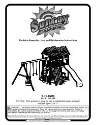
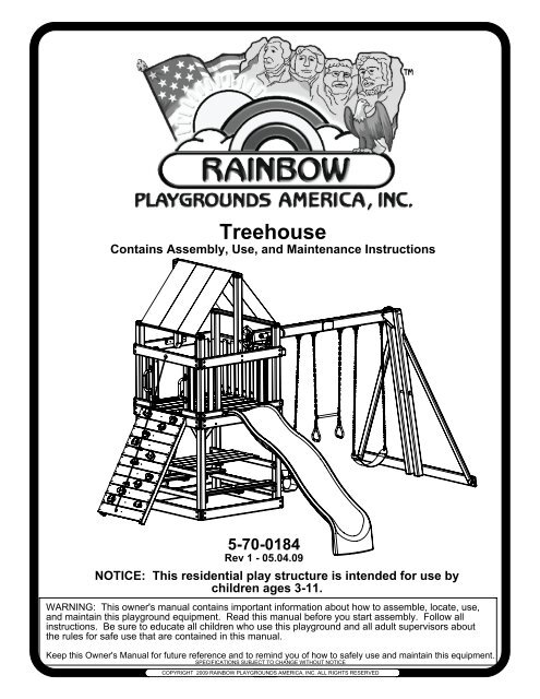
Treehouse<br />
Contains Assembly, Use, and Maintenance Instructions<br />
5-70-0184<br />
Rev 1 - 05.04.09<br />
NOTICE: This residential play structure is intended for use by<br />
children ages 3-<strong>11</strong>.<br />
WARNING: This owner's manual contains important information about how to assemble, locate, use,<br />
and maintain this playground equipment. Read this manual before you start assembly. Follow all<br />
instructions. Be sure to educate all children who use this playground and all adult supervisors about<br />
the rules for safe use that are contained in this manual.<br />
Keep this Owner's Manual for future reference and to remind you of how to safely use and maintain this equipment.<br />
SPECIFICATIONS SUBJECT TO CHANGE WITHOUT NOTICE<br />
COPYRIGHT 2009 RAINBOW PLAYGROUNDS AMERICA, INC. ALL RIGHTS RESERVED
NOTICE....IMPORTANT INFORMATION:<br />
PLEASE READ<br />
IF YOU ARE MISSING ANY PARTS,<br />
HAVE DAMAGED PARTS, OR ARE<br />
HAVING TROUBLE ASSEMBLING<br />
THIS PRODUCT, PLEASE CALL<br />
RAINBOW PLAYGROUNDS AMERICA, INC.<br />
CUSTOMER SERVICE CENTER<br />
AT 1-888-201-1570<br />
or<br />
E-Mail:<br />
customerservice@rainbowplaygroundsamerica.com<br />
Website: www.rainbowplaygroundsamerica.com<br />
CUSTOMER SERVICE HOURS:<br />
MONDAY - FRIDAY 8am - <strong>5pm</strong> <strong>cst</strong><br />
<strong>SATURDAYS</strong> (<strong>April</strong> <strong>11</strong> - <strong>June</strong> <strong>30</strong>) 8:<strong>30</strong>am - <strong>5pm</strong> <strong>cst</strong><br />
STOP<br />
DO NOT CONTACT OR GO DIRECTLY TO THE<br />
RETAILER THAT YOU PURCHASED THIS PRODUCT FROM.<br />
1
OWNER'S MANUAL<br />
Rainbow Playgrounds America, Inc.<br />
Thank you for choosing Rainbow Playgrounds America, Inc. For your<br />
and your children's safety, please read the instruction manual thoroughly<br />
before you start building your Rainbow Playgrounds America, Inc.<br />
playground. Familiarize yourself with all hardware and parts to help with<br />
building your playground. Make sure to send in your owner's registration<br />
card on the back cover in order to validate your warranty.<br />
WARNING: Failure to follow the assembly, location, use, and<br />
maintenance instructions in this manual could result<br />
in serious injury to children using this playground.<br />
Rules for Safe Play..........................................................................3<br />
Choosing Location of Play System..................................................4<br />
Choosing Proper Surface Material...................................................4<br />
Maintenance....................................................................................5<br />
Helpful Tips.....................................................................................6<br />
Commonly Asked Questions...........................................................7<br />
Wood Legend..................................................................................8<br />
Parts Identification...........................................................................9-14<br />
Hardware.........................................................................................15-17<br />
Tools Required for Assembly..........................................................18<br />
Instructions......................................................................................19-44<br />
Warranty Procedure........................................................................45<br />
Warranty..........................................................................................46-47<br />
Registration Card...................................................................Back Cover<br />
2
100% North American Timber<br />
The wooden parts for your playground are made from whitewood and trace amounts of Redwood and<br />
Cedar. Whitewood is the general commercial name that refers to the wood of spruce, pine and fir<br />
trees. Rainbow Playgrounds America, Inc. uses a blend of North American whitewood from the<br />
following species in each set: Engelmann Spruce, Lodgepole Pine, Douglas Fir, and Hemlock.<br />
Rainbow Playgrounds America, Inc. uses these woods in varying degrees and reserves the right to<br />
alter its specifications. This high-quality whitewood lumber is third-party inspected for sustainability by<br />
one or more of the following groups:<br />
FSC Forest Stewardship Council HCP Habitat Conservation Program<br />
SFI Scientific Forest Initiative CSA Canadian Standards Association<br />
Safety Instructions<br />
Rules for Safe Play<br />
WARNING: Before allowing children to play on this equipment for the first time,<br />
carefully review the rules for safe play with them. Observing the following<br />
statements and warnings reduces the likelihood of a serious or fatal injury.<br />
1. IT IS RECOMMENDED that no more than 8 children, not exceeding a combined weight of 1,000 pounds, play<br />
on the system at one time. This product is recommended for children 3 to <strong>11</strong> years of age.<br />
2. CLOSE ADULT SUPERVISION is required, especially for younger children.<br />
3. WARN CHILDREN TO AVOID playing or walking in front of, behind, or between moving equipment.<br />
4. WARN CHILDREN NOT TO twist swing chains or ropes, or to loop them over the top support bar since this<br />
may reduce the strength of the chain or rope.<br />
5. INSTRUCT CHILDREN NOT TO swing empty swinging seats.<br />
6. INSTRUCT CHILDREN to always sit, never stand or kneel, in the center of the swing seat with their full weight.<br />
7. INSTRUCT CHILDREN NOT TO use any part of the play system in a manner other than what it is intended.<br />
8. INSTRUCT CHILDREN NOT TO get off equipment while it is in motion.<br />
9. DRESS CHILDREN APPROPRIATELY. CHILDREN SHOULD NOT wear scarves, hats with straps, helmets,<br />
jackets with draw strings, hooded jackets, poorly fitting shoes, or any other loose fitting clothing which could<br />
become entangled or snagged on equipment.<br />
10. INSTRUCT CHILDREN NOT TO play on the equipment if it is wet. Potentially slippery surfaces may cause a<br />
hazard.<br />
<strong>11</strong>. VERIFY all suspended items such as ropes and chains are secure at both ends.<br />
12. VERIFY all suspended items such as climbing ropes are tight so they cannot be looped back on themselves.<br />
13. INSTRUCT CHILDREN NOT TO attach items to the play system not specifically intended for use with the<br />
play equipment. Items such as, but not limited to, jump ropes, clotheslines, and pet leashes may pose a<br />
strangulation hazard.<br />
14. INSTRUCT CHILDREN TO REMOVE any bike or other sports helmets before playing on the play equipment, as<br />
they may pose a possible hanging hazard.<br />
15. INSTRUCT CHILDREN there may only be one person on a swing at a time with a maximum weight of 150<br />
pounds per swing.<br />
16. VERIFY there are no gaps between the slide bed way and the slide screws.<br />
17. INSTRUCT CHILDREN to always go down slides feet first. Never slide head first.<br />
18. INSTRUCT CHILDREN TO NEVER climb, crawl, or walk on items not intended for such use. Such types of play<br />
on top of Monkey Bars, Fort Roof, and Swing Beams greatly increase the risk of a serious or fatal fall.<br />
3
Choosing a location for your play system<br />
When selecting your play site, always keep the child's safety in mind. Here are some recommendations that should help you achieve a safe<br />
play area.<br />
1. The play system should be located on solid level ground free of objects that could cause injury such as, but not limited to, tree stumps,<br />
roots, and large rocks. Stationary components such as ladders and slides must be no less than SIX FEET (1.8 meters) from any<br />
structure or obstruction such as a fence, garage, house, tree or overhanging branches, electrical wires or clotheslines. Any swinging<br />
equipment must be a minimum distance of TWICE the height of the swing beam away from any structures or obstructions as specified<br />
above. We also recommend that you do not install your play system near a lake, river, swimming pool or other water hazards.<br />
2. If anchoring your play system, all underground utilities must be located in play zone before starting assembly of play system.<br />
3. Try to locate slide out of direct sunlight to reduce the likelihood of serious burns. A slide that faces north will receive the least direct<br />
sunlight.<br />
4. It is recommended not to place a set on sandy soil or loose fill, as it may require additional anchoring in that situation.<br />
5. Do not install your play system over concrete, asphalt, packed earth, grass, carpet, or any other hard surface. A fall onto a hard surface<br />
can result in serious injury to the play system user.<br />
Set Dimensions Play Zone<br />
L 16' x W 14 1/2' x H 10' L 28' x W 29 1/2'<br />
29 1/2'<br />
6'<br />
MIN<br />
Choosing a surfacing material<br />
The consumer shall provide playground surfacing materials under and around residential play equipment that conforms to the<br />
recommendations of the Consumer Product Safety Commission's Outdoor Home Playground Safety Handbook publications #324. A copy<br />
of the section relating to surfacing materials is included in the installation instructions. Free copies of this handbook are available on line at<br />
www.cpsc.gov or by contacting the CPSC Publications Office in Washington D.C. 20207.<br />
The URL is http://www.cpsc.gov/cpscpub/pubs/324.pdf and the file size is 456.5KB<br />
Playground equipment should never be placed on hard surfaces such as concrete or asphalt. Do not use loose fill surfacing ontop of hard<br />
surfaces such as concrete or asphalt. While grass may appear to be acceptable, it may quickly turn to hard packed earth in areas of high<br />
traffic. Shredded bark mulch, wood chips, fine sand or fine gravel are considered to be acceptable shock absorbing surfaces when installed<br />
and maintained at a sufficient depth under and around playground equipment. The U.S. Product Safety Commission (CPSC) estimates that<br />
about 100,000 playground equipment-related injuries resulting from falls to the ground surface are treated annually in U.S. hospital's<br />
emergency rooms. Injuries involving this hazard pattern tend to be the most serious of all playground injuries, and have a potential to be<br />
fatal, particularly when the injury is to the head. The surface under and around playground equipment can be a major factor in determining<br />
the injury-causing potential of a fall. It is self evident that a fall onto a shock absorbing surface is less likely to cause a serious injury than a<br />
fall onto a hard surface.<br />
The following information is intended to assist in comparing the relative shock-absorbing properties of various materials. No particular<br />
material is recommended over another. However, each material is only effective when properly maintained. Materials should be checked<br />
periodically and replenished to maintain correct depth as determined necessary for your equipment. The choice of a material depends on<br />
the type and height of your playground equipment, the availability of the material in your area, and its cost.<br />
Table 3.1 lists the maximum height from which a child would not be expected to sustain a life-threatening head injury in a fall onto four<br />
different loose-fill surfacing materials if they are installed and maintained at depths of 6, 9, and 12 inches. However, it should be recognized<br />
that all injuries due to falls cannot be prevented no matter what surfacing material is used.<br />
4<br />
9'<br />
MIN<br />
28'<br />
6'<br />
MIN<br />
6'<br />
MIN
Maximum Fall Height is 7'<br />
TABLE 3.1 Fall Height in Feet From Which a Life Threatening Head Injury Would Not Be Expected<br />
Type of Material 6 in. depth 9 in. depth 12 in. depth<br />
Double Shredded Bark Mulch 6 ft. 10 ft. <strong>11</strong> ft.<br />
Wood Chips 6 ft. 7 ft. 12 ft.<br />
Fine Sand 5 ft. 5 ft. 9 ft.<br />
Fine Gravel 6 ft. 7 ft. 10 ft.<br />
Surfacing in "compressed" depths - See CPS & ASTM for Fall Heights of equipment<br />
Equipment Fall Height 1' 2' 3' 4' 5' 6' 7' 8' 9' 10' <strong>11</strong>' 12'<br />
Wood Chips 6" 6" 6" 6" 6" 6" 6 1/2" 7 1/2" 8 1/4" 9" 12" 13"<br />
Double Shredded Bark Mulch 6" 6" 6" 6" 7" 8" 9" 9 3/4" 10 1/2" <strong>11</strong> 1/2" 12" 13"<br />
Engineered Wood Fibers 6" 6" 6" 7" 8 1/2" 9" 9 1/2" 10 1/4" 10 3/4" <strong>11</strong>" 10 3/4" 12"<br />
Fine Sand 6" 6" 6 1/2" 8" 9 10" 10 1/2" <strong>11</strong> 1/4" 12" 13 1/2" 14 3/4" 16"<br />
Coarse Sand 6" 6" 7 1/2" 9" 10 1/2" 12" 14" 16" 18" 20" 22" 24"<br />
Fine Gravel 6" 6" 6" 6 3/4" 8" 9" 10" 10 3/4" <strong>11</strong> 1/2" 12" 13 1/4" 14 1/2"<br />
Medium Gravel 6" 6 1/4" 8" 9" 9" 12" 14" 16" 18" 20" 22" 24"<br />
Chart obtained from U.S. Consumer Product Safety Commission Handbook for Public Playground Safety<br />
NOTICE: It is recommended to use containment, such as digging out around the perimeter and/or lining the<br />
perimeter with landscape edging for surfacing materials.<br />
Installations of rubber tiles or poured-in-place surfaces (other than loose-fill materials) generally require a<br />
professional and are not "do-it-yourself" projects.<br />
When surfacing is to be used it is recommended to use Playground Surfacing Materials (other than loose-fill<br />
materials) which comply to the safety standard ASTM 1292 Standard Specification for Impact Attenuation of<br />
Surfacing Materials within the Use Zone of Playground Equipment.<br />
Assembly safety<br />
1. Wear safety glasses to protect your eyes from flying wood chips when drilling or cutting.<br />
2. Verify that all bolts and screws are secured tightly and all acorn nuts are snug (acorn nuts should be<br />
tightened to 5 foot pounds of torque).<br />
3. DO NOT allow children to play on the play system until it is completely assembled in a proper location.<br />
4. DO NOT allow children in the area while you are assembling your play system. Many of the Rainbow<br />
Playgrounds America Inc. components are very heavy and could seriously injure a child.<br />
Maintenance of your play system<br />
To ensure safe enjoyment of your Rainbow Playgrounds America play system for years to come, follow<br />
these maintenance tips at the beginning of each play season:<br />
1. At the beginning of each usage season and twice each month, check and tighten as needed (but do not over<br />
tighten causing wood to crack) all nuts and bolts. Acorn nuts should be tightened to 5 foot pounds of torque.<br />
Hardware used on swinging elements should be checked at least twice a month to ensure proper fastening.<br />
2. Oil all metallic moving parts and grease tire swivel monthly during the usage period.<br />
3. Verify all moving parts including swing seats, ropes, and chains for wear, rust, or other deterioration and replace<br />
as needed.<br />
4. Check all metal parts for rust. If needed, sand and repaint using a nonlead-based paint meeting the<br />
requirements of Title 16 CFR Part 1<strong>30</strong>3.<br />
5. Check all wood members for deterioration and splinters. Spot sand any areas that are checking or<br />
splintering. If parts are deteriorating replace as needed.<br />
6. Remove plastic swing seats and take indoors or do not use when temperature drops below<br />
36 Fahrenheit.<br />
7. Check, twice a month, the depth of loose fill protective surfacing materials to prevent compaction<br />
and to maintain appropriate depth. Rake or replace as necessary.<br />
5
8. Check the C-Links on the chain to ensure they are securely closed. Tighten with a crescent wrench as<br />
needed.<br />
9. On a yearly basis, we recommend that you coat your play system with a sealant or preservative. You may<br />
also want to spot sand areas before sealing. Be sure that the sealant you select is non-toxic and child safe.<br />
10. When you are ready to dispose of your play set, make sure all metal, plastic and wood components are<br />
disposed of in accordance with local waste ordinances.<br />
UPRIGHT<br />
PILOT<br />
HOLES<br />
Helpful Installation Hints<br />
*NOTE: Refer to these assembly tips throughout the entire installation process.<br />
1. After thoroughly reading all information and properly locating your play system site, carefully<br />
unpack parts. As you unpack your play system, keep the parts list handy and become familiar with each<br />
part before beginning assembly. Remember that a little extra time spent familiarizing yourself with the parts<br />
and instructions before you begin will help avoid mistakes and save you time later.<br />
2. Group both wood and non-wood parts together in accordance to each Step of this assembly manual. Doing<br />
this now, will help you quickly locate parts and assemble the set with more ease.<br />
3. Locate an area to sort your hardware in accordance to each step. A solid surface, such as the empty boxes,<br />
are best to ensure you do not lose any hardware.<br />
4. Before starting each Step, thoroughly read the entire instructions to ensure all information is understood.<br />
Pay special attention to the orientation of each part, details & notes, and proper usage of hardware. Each<br />
piece of hardware is required for a certain part of the assembly.<br />
5. Certain Steps of the assembly are best performed on a hard flat surface to ensure proper and accurate<br />
assembly.<br />
6. All Lag Bolts must have pre-drilled holes 2" deep (as shown in Detail A). Use a 1/8" drill bit for all 1/4" and<br />
5/16" Lag Bolts and use a 1/4" drill bit for all 3/8" Lag Bolts. Lag Bolts can be difficult to drill into knot holes.<br />
Pre-drilling pilot holes will help to prevent the Lag Bolts from breaking. Refer to "Commonly Asked Questions"<br />
on page 7 for more information about Lag Bolts.<br />
7. All #14 Phillips Pan Head Tap Screws must have pre-drilled holes 1/2" deep. Use a 1/8" drill bit.<br />
8. Use a clamp to secure Facias flush to the Uprights and use holes in facia as a guide for placing Lag<br />
Bolt Pilot Holes (as shown in Detail B).<br />
9. Verify Facias are flush with Uprights.<br />
10. Check assembly periodically to ensure the set is level and all facias are square to the uprights.<br />
<strong>11</strong>. If a gap occurs between boards when inserting Screws or Lag Bolts, back out hardware and apply pressure to<br />
the top board while reinserting hardware in the same hole.<br />
DETAIL A<br />
FACIA<br />
FACES MUST<br />
BE FLUSH<br />
6<br />
DETAIL B<br />
USE FACIA AS<br />
A GUIDE FOR<br />
PRE-DRILLING<br />
HOLES
COMMONLY ASKED QUESTIONS<br />
Question: How do I know when Lag Bolts and other Fasteners are tightened properly?<br />
Answer: Lag Bolts and other Fasteners are tight when the head of the Lag Bolt and Washer<br />
are firmly compressed against the wood. If splintering occurs, that is an indication you<br />
are over tightening the Lag Bolts and other Fasteners. (Splintering is when the wood<br />
fibers fracture out from under the washers).<br />
Question: What should I do if a Lag Bolt or other Fastener lines up with a knot, or if the Lag Bolt<br />
breaks?<br />
Answer: There is extra Hardware provided with the set for this reason. Re-Drill a new hole with<br />
a 1/8" Drill Bit in a new direction to miss the obstruction.<br />
Question: What if my Play System is leaning and/or rocks?<br />
Answer: This is caused by unleveled ground under the Base and Support Wings of the Play<br />
System. It may be necessary to remove or add some soil beneath the Play System<br />
to make it level. Ground Stakes, when installed, will also provide stability.<br />
Question: What if my Play System has cracks on the wood or seems to be developing cracks?<br />
Answer: Seasonal checks, surface cracks, and knot holes are natural characteristics of all<br />
wooden play equipment. A check is a separation of the wood fibers running with the<br />
grain. This is caused by varying temperature and moisture conditions. By coating<br />
your Play System annually with a sealant or preservative, you can help protect your<br />
Play System from developing (not stopping) seasonal checks. Please remember to<br />
follow all installation instructions, including installing the play set on solid level ground.<br />
Question: What is the sticky substance that appears on the wood?<br />
Answer: The sticky substance that may appear on the wood is called pitch. It is common for<br />
the lumber to have occasional pitch seepage which does not affect the structural<br />
integrity of the part. Pitch provides the natural rot resistant characteristics of the<br />
lumber. If play surfaces or play items become overly sticky with pitch use rubbing<br />
alcohol to safely remove.<br />
Question: What accessories may be added or what modifications can be made to my Rainbow<br />
Playgrounds America set?<br />
Answer: Rainbow Playgrounds America, Inc. play sets are complete kits and are not modular.<br />
Play sets with unauthorized accessories or modifications will not be covered under<br />
warranty. Non-residential use of the play set voids warranty.<br />
Question: Is my child old enough to use all play items on my set?<br />
Answer: All play items on Rainbow Playgrounds America, Inc.<br />
sets are designed for children ages 3 to <strong>11</strong>, but it is the<br />
end users responsibility to determine suitability of use<br />
by their children for each play item.<br />
7<br />
EXAMPLE OF SEASONAL<br />
CHECKS OR SURFACE<br />
CRACKS
1 x 6 = 5/8" x 5 1/4" 1 x 4 = 5/8" x 3 1/4"<br />
2 x 4 = 1 3/8" x 3 1/4"<br />
Wood Legend<br />
4 x 4 = 3 3/8" x 3 3/8"<br />
*PICTURE NOT SHOWN: 4 x 6 = 3 3/8" x 5 3/8"<br />
8<br />
2 x 6 = 1 3/8" x 5 1/4"<br />
2 x 10 = 1 1/2" x 9 1/4"
4<br />
5<br />
6<br />
<strong>11</strong><br />
12<br />
13<br />
14<br />
15<br />
16<br />
25<br />
26<br />
27<br />
28<br />
29<br />
<strong>30</strong><br />
2 @ 1 x 4 x 45 1/4" SHORT DECK BOARD<br />
4 @ 1 x 4 x 52" DECK BOARD<br />
13 @ 1 x 4 x 27 1/2" RAIL UPRIGHT<br />
6 @ 1 x 6 x 52" DECK BOARD<br />
4 @ 1 x 6 x 47 1/2" TABLE BOARD<br />
2 @ 1 x 6 x 34 1/2" 4 HOLE R W B<br />
6 @ 1 x 6 x 34 1/2" 2 HOLE INSIDE R W B<br />
1 @ 1 x 6 x 34 1/2" R W B W/ROPE HOLE<br />
2 @ 1 x 6 x 34 1/2" 2 HOLE OUTSIDE R W B<br />
2 @ 2 x 4 x 27 1/2" RAIL UPRIGHT<br />
2 @ 2 x 4 x 84" SWING BEAM WING<br />
4 @ 2 x 4 x 27 1/2" RAIL UPRIGHT W/HANDLE HOLES<br />
8 @ 2 x 4 x 52" 2 HOLE FACIA<br />
6 @ 2 x 4 x 13 3/4" CORNER FACIA<br />
2 @ 2 x 4 x 45 1/4 SEAT BOARD<br />
PARTS IDENTIFICATION<br />
9
31<br />
32<br />
33<br />
34<br />
35<br />
36<br />
48<br />
49<br />
50<br />
52<br />
53<br />
54<br />
55<br />
1 @ 2 x 4 x 20" TABLE RUNNER<br />
2 @ 2 x 4 x 8" SEAT RUNNER<br />
1 @ 2 x 4 x 19 3/4" ENTRAPMENT BOARD<br />
2 @ 2 x 4 x 59" ROCK WALL LEG<br />
1 @ 2 x 4 x 51" DECK RUNNER<br />
1 @ 2 x 4 x 56" ROCK WALL RUNNER<br />
1 @ 2 x 6 x 93" GROUND RUNNER<br />
4 @ 2 x 6 x 52" MAIN BEAM<br />
5 @ 2 x 6 x 52" 4 HOLE FACIA<br />
1 @ 2 x 6 x 52" 4 HOLE FACIA W/ROPE HOLE<br />
2 @ 2 x 6 x 50" SEAT BOARD<br />
1 @ 2 x 6 x 55 1/2" LEFT LADDER LEG<br />
1 @ 2 x 6 x 55 1/2" RIGHT LADDER LEG<br />
56 168<br />
PARTS IDENTIFICATION<br />
4 @ 2 x 6 x 18" LADDER STEP 2 @ 2 x 6 x 52" 6 HOLE FACIA<br />
10
77<br />
78<br />
79<br />
169<br />
170<br />
171<br />
81<br />
1 @ 4 x 4 x 52" TOP JOIST W/SWING HOLES<br />
8 @ 4 x 4 x 15" ANGLED BRACE<br />
2 @ 4 x 4 x 88" SWING BEAM SUPPORT<br />
2 @ 4 x 4 x 93" CORNER UPRIGHT<br />
2 @ 4 x 4 x 93" CORNER UPRIGHT W/TJ HOLE<br />
2 @ 4 x 4 x 44" CENTER POST<br />
1 @ 4 x 6 x 94" 3 POSITION SWING BEAM<br />
PARTS IDENTIFICATION<br />
<strong>11</strong>
N8 N10<br />
8 @ 90 Bracket<br />
N29<br />
12 @ Bolt Cup<br />
N20<br />
1 @ Ship's Wheel w/Cap<br />
N4<br />
1 @ Support Spacer<br />
N<strong>30</strong><br />
N15<br />
2 @ Swing Seat<br />
N33<br />
2 @ T-Bracket<br />
6 @ C-Link<br />
PARTS IDENTIFICATION<br />
1 @ Swing Beam Plate<br />
N19<br />
N17<br />
N28<br />
1 @ Telescope<br />
1 @ Half Bucket Swing<br />
Designed for ages 3-5<br />
N13<br />
6 @ 58" Chain<br />
N31<br />
4 @ Pear Link<br />
N<strong>11</strong> N9<br />
2 @ SB Support Plate<br />
N26<br />
6 @ Rebar Stake 6 @ Swing Hanger<br />
12<br />
N22<br />
N12<br />
12 @ Rocks<br />
N18<br />
1 @ Trapeze Bar<br />
2 @ 34" Chain<br />
N24<br />
N1<br />
4 @ 90 Ladder Bracket<br />
N5<br />
N27<br />
6 @ Spring Clip<br />
4 @ Safety Handle<br />
N23<br />
N14<br />
2 @ Trapeze Ring<br />
1 @ Plaque<br />
Parts Not Shown:<br />
1 @ Double Wall Wave Slide<br />
1 @ 12' Rope
PARTS IDENTIFICATION<br />
N58<br />
28<br />
171<br />
N20<br />
N19<br />
28<br />
170<br />
N33<br />
81 N<strong>11</strong><br />
N23<br />
168<br />
N<strong>11</strong><br />
169<br />
25<br />
29<br />
13<br />
26<br />
78<br />
49<br />
12<br />
N4<br />
31<br />
N18<br />
N14<br />
79<br />
36<br />
N15<br />
28<br />
26<br />
28<br />
32<br />
N24<br />
48<br />
N17<br />
170<br />
<strong>30</strong><br />
50
171<br />
81<br />
N<strong>11</strong><br />
169<br />
N27<br />
52<br />
N26<br />
N5<br />
26<br />
N4<br />
14<br />
13<br />
14<br />
79<br />
14<br />
33<br />
16<br />
14<br />
14<br />
16<br />
N15<br />
14<br />
48<br />
14<br />
13<br />
15<br />
169<br />
56<br />
50<br />
50<br />
54<br />
55
H152<br />
H155<br />
H<strong>30</strong><br />
H32<br />
H34<br />
H28<br />
H17<br />
H24<br />
HARDWARE FOR ASSEMBLY<br />
H1<br />
H158<br />
H163<br />
H164<br />
H170<br />
H192<br />
H7 H<strong>11</strong><br />
H4 H3<br />
15<br />
H183<br />
0<br />
1<br />
2<br />
3<br />
4<br />
5<br />
6<br />
7<br />
8<br />
9
H140<br />
HARDWARE FOR ASSEMBLY<br />
H139<br />
H135<br />
16<br />
H124<br />
H129<br />
H126<br />
0<br />
1<br />
2<br />
3<br />
4<br />
5<br />
6<br />
7<br />
8<br />
9
H60<br />
HARDWARE FOR ASSEMBLY<br />
H56<br />
H93<br />
17<br />
H50<br />
H108<br />
H<strong>11</strong>6<br />
0<br />
1<br />
2<br />
3<br />
4<br />
5<br />
6<br />
7<br />
8<br />
9
EXAMPLE: 5-46-0506* @ 2**<br />
Hardware List<br />
F/N# DESCRIPTION DIMENSION BAG/QTY<br />
H1 Flat Washer 1/4" 5-46-0506 @2, 5-46-0515 @90<br />
H3 Flat Washer 3/8" 5-46-0410 @4, 5-46-0506 @23, 5-46-0515 @2<br />
H4 Flat Washer 1/2" 5-46-0506 @4, 5-46-0515 @2<br />
H7 SAE Flat Washer 1/4" 5-46-0515 @28<br />
H<strong>11</strong> Lock Washer 3/8" 5-46-0410 @4, 5-46-0506 @20, 5-46-0515 @6<br />
H17 Standard Nut 3/8" 5-46-0506 @5, 5-46-0515 @2<br />
H24 Nylock Nut 3/8" 5-46-0410 @4, 5-46-0506 @8<br />
H28 Acorn Nut 3/8" 5-46-0410 @4, 5-46-0506 @13<br />
H<strong>30</strong> Round Pallet Nut 3/8" 5-46-0506 @6<br />
H32 4 Prong T-Nut 1/4" 5-46-0515 @32<br />
H34 4 Prong T-Nut 3/8" 5-46-0515 @4<br />
H50 Carriage Bolt 3/8" x 3 1/2" 5-46-0506 @2<br />
H56 Carriage Bolt 3/8" x 6 1/2" 5-46-0506 @1, 5-46-0515 @2<br />
H60 Carriage Bolt 3/8" x 8 1/2" 5-46-0506 @1<br />
H93 Lag Bolt 1/4" x 2" 5-46-0515 @6<br />
H108 Lag Bolt 5/16" x 3" 5-46-0506 @2, 5-46-0515 @90<br />
H<strong>11</strong>6 Lag Bolt 3/8" x 3 1/2" 5-46-0506 @ 2<br />
H124 Hex Bolt 3/8" x 1 1/2" 5-46-0515 @4<br />
H126 Hex Bolt 3/8" x 2" 5-46-0506 @2<br />
H129 Hex Bolt 3/8" x 3 1/2" 5-46-0506 @3<br />
H135 Hex Bolt 3/8" x 6 1/2" 5-46-0410 @ 4, 5-46-0506 @8<br />
H139 Hex Bolt 3/8" x 9" 5-46-0506 @1<br />
H140 Hex Bolt 3/8" x 10" 5-46-0506 @1<br />
H152 Phillips Wood Screw #8 x 1 1/2" 5-46-0515 @175<br />
H155 Phillips Wood Screw #8 x 2 1/2" 5-46-0515 @62<br />
H158 Phillips Pan Head Tap Screw #10 x 1 1/2" 5-46-0515 @4<br />
H163 Phillips Pan Head Tap Screw #14 x 3/4" 5-46-0515 @6<br />
H164 Phillips Pan Head Tap Screw #14 x 1" 5-46-0515 @38<br />
H170 Phillips Pan Head Machine Screw 1/4" x 1 1/4" 5-46-0515 @24<br />
H192 Phillips Pan Head Machine Screw 1/4" x 1 1/2" 5-46-0515 @8<br />
H183 Snap Screw #10 x 1" Rolled up in Tarp<br />
*DENOTES HARDWARE BAG<br />
**DENOTES QUANTITY NEEDED OUT OF HARDWARE BAG<br />
NOTE: EXTRA HARDWARE IS INCLUDED IN THE BAGS.<br />
NOT ALL HARDWARE WILL BE USED TO COMPLETE THE INSTALLATION.<br />
TOOLS REQUIRED FOR ASSEMBLY<br />
Tape Measure<br />
Carpenters Level<br />
Carpenters Square<br />
Claw Hammer<br />
Rubber Mallet<br />
Wood Clamp<br />
Standard or Cordless Drill w/ #2 & #3 Phillips bits<br />
Electric Impact Gun or 1/4" and 3/8" Ratchet<br />
1/8" Drill Bit<br />
1/4" Drill Bit<br />
18<br />
Crescent Wrench<br />
Torque Wrench<br />
7/16" Deep Well Socket<br />
1/2" Deep Well Socket<br />
9/16" Deep Well Socket<br />
9/16" Box Wrench<br />
8' Step Ladder<br />
Safety Glasses<br />
Adult Helper
50<br />
Step 1<br />
*NOTE: Pre-drill all holes for Lag Bolts with the appropriate drill bit. Use an 1/8" drill bit for<br />
pre-drilling holes for 5/16" Hardware (H108).<br />
*NOTE: Do not tighten hardware in #1 at this time.<br />
1. Lay Corner Uprights (169) (170) on the ground. Attach Top Joist w/Swing Holes (77) to Corner<br />
Uprights (170) using 3/8" Hardware (H3) (H<strong>11</strong>) (H17) (H56) and 1/2" Hardware (H4).<br />
*NOTE: 4 Hole Facias (50) must be flush with the bottoms and sides of Corner Uprights<br />
(169) (170), and they must be oriented as shown in Detail A.<br />
*NOTE: Corner Uprights (169) (170) should measure 52" from outside face to outside face<br />
when properly installed (as shown).<br />
*SUGGESTION: When installing Facias, install bottom lag bolts first, check that<br />
measurements are correct and assembly is square, then install top lag bolts.<br />
2. Attach 4 Hole Facias (50) to Corner Uprights (169) (170) using 1/4" Hardware (H1) and 5/16"<br />
Hardware (H108).<br />
3. Measure up 82 7/8" from the bottom of Corner Uprights (169) and attach 4 Hole Facia w/Rope<br />
Hole (52) to Corner Uprights (169) using 1/4" Hardware (H1) and 5/16" Hardware (H108). The<br />
Facia (52) must be oriented as shown in Detail B.<br />
1 1/4"<br />
52<br />
169 170<br />
DETAIL A<br />
169<br />
DETAIL B<br />
1 1/4"<br />
1 3/4"<br />
82 7/8"<br />
H108 H1<br />
Upright Assembly<br />
52<br />
50<br />
170<br />
169<br />
19<br />
52"<br />
77<br />
H56<br />
50<br />
H4<br />
H17<br />
H3<br />
H<strong>11</strong><br />
170
Step 2<br />
1 1/4"<br />
52<br />
1 1/4"<br />
50<br />
DETAIL A<br />
DETAIL B<br />
H108 H1<br />
1 3/4"<br />
168<br />
168<br />
1 3/4"<br />
50<br />
50<br />
50<br />
Upright Assembly<br />
*NOTE: Pre-drill all holes for Lag Bolts with the appropriate drill bit.<br />
*NOTE: Holes in 4 Hole Facias (50) and 6 Hole Facias (168) must be offset (as shown in<br />
Details A & B).<br />
*NOTE: 4 Hole Facias (50) must be flush with the bottoms and sides of Corner Uprights<br />
(169) (170), and they must be oriented as shown in Detail A.<br />
*NOTE: Corner Uprights (169) (170) should measure 52" from outside face to outside face<br />
when properly installed (as shown).<br />
*SUGGESTION: When installing Facias, install bottom lag bolts first, check that<br />
measurements are correct and assembly is square, then install top lag bolts.<br />
1. Stand up each assembly from Step 1 and attach 4 Hole Facias (50) and 6 Hole Facias (168) to<br />
Corner Uprights (169) (170) using 1/4" Hardware (H1) and 5/16" Hardware (H108).<br />
*NOTE: Bottoms of 6 Hole Facias (168) should be flush with the bottoms of Facia (52) and<br />
Top Joist (77).<br />
2. Check that assembly is square with a carpenters square and ensure all measurements are<br />
correct.<br />
3. Tighten hardware from #1 of Step 1, add 3/8" Acorn Nut (H28) and tighten.<br />
52<br />
52"<br />
170<br />
169<br />
20<br />
52"<br />
H28<br />
77<br />
50<br />
168<br />
50<br />
H1<br />
H1<br />
H28<br />
H108<br />
170<br />
H108
Step 3<br />
50<br />
52<br />
50<br />
170<br />
169 169<br />
H1<br />
H108<br />
Main Beam Installation<br />
*NOTE: Pre-drill all holes for Lag Bolts with the appropriate drill bit.<br />
1. Measure up 51 3/8" from the bottom of Uprights (169) (170) (as shown) and lightly mark the<br />
uprights.<br />
*NOTE: Offset counter-sunk holes in Main Beams (49) must be down (as shown).<br />
2. Orient Main Beams (49) (as shown) and attach to Uprights (169) (170) using 1/4" Hardware (H1)<br />
and 5/16" Hardware (H108).<br />
49<br />
21<br />
1 3/4"<br />
H108<br />
H1<br />
50<br />
50<br />
170<br />
51 3/8"
Step 4a<br />
*NOTE: Pre-drill all holes for Lag Bolts with the appropriate drill bit.<br />
1. Measure up <strong>11</strong> 3/4" and 24 1/4" on Corner Uprights (169) (170) and attach 2 Hole Facias (28) <strong>11</strong><br />
3/4" up using 1/4" Hardware (H1) and 5/16" Hardware (H108).<br />
2. Center and attach Seat Boards (<strong>30</strong>) (53) to 2 Hole Facias (28) using #8 Hardware (H155).<br />
3. Center and attach Seat Runners (32) to Seat Boards (<strong>30</strong>) (53) using #8 Hardware (H155).<br />
169<br />
Step 4b<br />
28<br />
169<br />
170<br />
H108 H1<br />
12<br />
<strong>30</strong><br />
Picnic Table Assembly<br />
170<br />
53<br />
28<br />
Picnic Table Assembly<br />
31<br />
169<br />
H152<br />
12<br />
H155<br />
170<br />
H1 H108<br />
169<br />
32<br />
170<br />
24 1/4"<br />
<strong>11</strong> 3/4"<br />
*NOTE: Pre-drill all holes for Lag Bolts with the appropriate drill bit.<br />
1. Attach 2 Hole Facias (28) to Corner Uprights (169) (170), 24 1/4" up, using 1/4" Hardware (H1) and<br />
5/16" Hardware (H108).<br />
*NOTE: #8 Screws (H152) used to attach table boards are shorter than the #8 Screws (H155)<br />
used to attach the Seat Boards in Step 4a.<br />
2. Center Table Boards (12) on 2 Hole Facias (28) and attach using #8 Hardware (H152).<br />
3. Center and attach Table Runner (31) to Table Boards (12) using #8 Hardware (H152).<br />
22
Step 5<br />
4<br />
5 <strong>11</strong><br />
49<br />
Deck Assembly<br />
1. Center and evenly space Deck Boards (4) (5) (<strong>11</strong>) between Uprights and attach Deck Boards to<br />
Main Beams (49) using #8 Hardware (H152).<br />
*NOTE: Deck Boards (4) (5) (<strong>11</strong>) must be evenly spaced, and gaps between boards must<br />
not exceed 3/16".<br />
2. Center and attach Deck Runner (35) to Deck Boards using #8 Hardware (H152).<br />
23<br />
35<br />
H152<br />
49
Step 6<br />
169<br />
78<br />
H1<br />
H108<br />
170<br />
49<br />
Angled Brace Installation<br />
*NOTE: Pre-drill all holes for Lag Bolts with the appropriate drill bit.<br />
1. Attach Angled Braces (78) to Corner Uprights (169) (170) using 1/4" Hardware (H1) and 5/16"<br />
Hardware (H108). The tops of the Angled Braces (78) should be touching the bottom of the Deck<br />
Boards. A total of 8 Angled Braces (78) will be installed.<br />
2. Attach Angled Braces (78) to Main Beams (49) using 1/4" Hardware (H1) and 5/16" Hardware (H108).<br />
169<br />
24<br />
H1<br />
H108<br />
78<br />
49<br />
78<br />
170
H108<br />
Step 7<br />
H1<br />
169<br />
49<br />
29<br />
50 29<br />
170<br />
Facia Installation<br />
*NOTE: Pre-drill all holes for Lag Bolts with appropriate drill bit.<br />
1. Attach 4 Hole Facia (50) and Main Beams (49) to Corner Uprights (169) (170) using 1/4" Hardware<br />
(H1) and 5/16" Hardware (H108). The tops of the Facias (50) and Main Beams (49) should be flush<br />
with the tops of the Deck Boards.<br />
*NOTE: Main Beams (49) must be oriented with the offset counter-sunk holes down.<br />
2. Attach Main Beams (49) to Angled Braces (78) using 5/16" Hardware (H108) and 1/4" Hardware<br />
(H1).<br />
3. Attach Corner Facias (29) to Corner Uprights (169) (170) using 1/4" Hardware (H1) and 5/16"<br />
Hardware (H108). Corner Facias (29) should rest on top of 4 Hole Facia (50) and Main Beams (49).<br />
4. Attach 2 Hole Facia (28) to Corner Uprights (170) using 1/4" Hardware (H1) and 5/16" Hardware<br />
(H108). The top of the 2 Hole Facia (28) should be flush with the tops of the Corner Facias (29)<br />
(as shown in Detail A).<br />
25<br />
169<br />
28<br />
49<br />
170<br />
49<br />
H1<br />
29<br />
H108<br />
TOPS FLUSH<br />
DETAIL A<br />
170<br />
28
Step 8<br />
35<br />
H164<br />
49<br />
N8<br />
DETAIL A<br />
Deck Bracket Installation<br />
*NOTE: Pre-drill holes 1/2" deep for #14 Hardware (H164) with a 1/8" drill bit.<br />
1. Attach 90 Bracket (N8), in 2 locations, to Deck Runner (35) and Main Beams (49) on both ends of<br />
the Deck Runner (35) using #14 Hardware (H164) (as shown in Detail A).<br />
35<br />
H164<br />
N8<br />
49<br />
*NOTE: This view is from the under-side of the deck.<br />
26<br />
49
Step 9<br />
H155<br />
56<br />
BACK<br />
Ladder Assembly<br />
1. Place Left Ladder Leg (54) and Right Ladder Leg (55) on a flat surface with the notches facing up.<br />
Insert 3/8" Hardware (H34) into holes in Ladder Legs, using a hammer if needed (as shown in<br />
Inset A).<br />
2. Attach Ladder Steps (56) to Left Ladder Leg (54) and Right Ladder Leg (55) using #8 Hardware<br />
(H155).<br />
3. Attach Entrapment Board (33) to the BACK side of the ladder, 5 1/2" down from the top of the<br />
Ladder Legs (54) (55) using #8 Hardware (H155).<br />
*NOTE: The back side of the ladder is the side closest to the holes in the Ladder Legs.<br />
4. Attach 90 Ladder Brackets (N9) to the Ladder Legs (54) (55) using 3/8" Hardware (H<strong>11</strong>) (H124)<br />
(H34).<br />
*NOTE: Do not tighten Ladder Bracket hardware at this time.<br />
54<br />
55<br />
27<br />
H155<br />
55<br />
54<br />
33<br />
54<br />
55<br />
INSET A<br />
H<strong>11</strong><br />
H34<br />
5 1/2"<br />
H124<br />
N9<br />
H34
Step 10<br />
1. Position Ladder Assembly against Main Beam (49). Ladder should be centered horizontally on<br />
the Main Beam (49) and 90 Ladder Brackets (N9) should be centered vertically on the Facia.<br />
*NOTE: Pre-drill holes 1/2" deep for #14 Hardware (H164) with a 1/8" drill bit.<br />
2. Attach 90 Ladder Brackets (N9) to Main Beam (49) using #14 Hardware (H164).<br />
3. Tighten 3/8" Hardware in 90 Ladder Bracket (N9) at this time.<br />
49<br />
N9<br />
H164<br />
Ladder Installation<br />
H164 N9<br />
28
Step <strong>11</strong> Rail Uprights Installation<br />
1. Place Rail Uprights with Handle Holes (27) on the ground and use a hammer to pound 1/4" T-Nuts<br />
(H32) into the Uprights (as shown in Detail A).<br />
2. In the locations shown, place Rail Uprights (25) and Rail Uprights with Handle Holes (27), with the<br />
T-Nuts towards the inside of the set, and attach to 6 Hole Facias (168), 4 Hole Facia with Rope<br />
Hole (52), and Corner Facias (29) using #8 Hardware (H155). Rail Uprights (25) (27) should be<br />
flush with the outside edge of the Corner Facias (29).<br />
*NOTE: #8 Hardware (H152) used to attach 1 x 4 Rail Uprights (6) is shorter than the #8<br />
Hardware (H155) used to attach 2 x 4 Rail Uprights (25) (27).<br />
3. Center 1 x 4 Rail Uprights (6) between Corner Uprights and 2 x 4 Rail Uprights (25) (27) and attach<br />
to Facias (29) (52) (168) using #8 Hardware (H152).<br />
4. Measure over 2 13/16" from Corner Upright (170) and attach first Upright (6) to Top Joist (77) and<br />
2 Hole Facia (28). Space the remaining Rail Uprights (6) approximately 2 13/16" apart and attach<br />
using #8 Hardware (H152).<br />
*NOTE: Gaps between Rail Uprights (6) must be less than 3 3/8". It may be necessary to<br />
adjust Rail Uprights (6) to ensure gaps are less than 3 3/8".<br />
29<br />
52<br />
6<br />
169<br />
168<br />
27<br />
27<br />
H155<br />
H32<br />
6<br />
6<br />
170<br />
H152<br />
2 13/16"<br />
29<br />
6 H152<br />
DETAIL A<br />
25<br />
77<br />
H32<br />
27<br />
170<br />
168<br />
6<br />
28<br />
29
Step 12<br />
N5<br />
27<br />
Safety Handle &<br />
90 Bracket Installation<br />
1. Attach Safety Handles (N5) to Rail Uprights with Handle Holes (27) using 1/4" Hardware (H192).<br />
*NOTE: Pre-drill holes for #14 Hardware (H163) (H164) with a 1/8" drill bit.<br />
*NOTE: Position 90 Brackets so that the hardware does not hit the gaps between<br />
Deck Boards.<br />
2. Position 90 Brackets (N8) on Deck and up against Rail Uprights (25) (27) and attach using<br />
#14 Hardware (H163) (H164). The #14 Hardware (H163) must go through 90 Bracket (N8)<br />
and into Deck (as shown in Detail A).<br />
SHORTER #14 HARDWARE<br />
(H163) MUST GO INTO DECK<br />
N5<br />
<strong>30</strong><br />
H164<br />
25<br />
H163<br />
DETAIL A<br />
25 27<br />
N8<br />
27<br />
H192<br />
N5
Step 13<br />
Rockwall Assembly<br />
1. Lay 2 Hole Rockwall Boards (14) (16), 4 Hole Rockwall Boards (13), and Rockwall Legs (34) on a<br />
flat, hard surface. Use a hammer to pound in 1/4" Hardware (H32) and 3/8" Hardware (H34) (as<br />
shown in Inset A). Rockwall Legs (34) must be orientated as shown in Inset A.<br />
2. On a flat surface, lay Rockwall Legs (34) on edge with holes up. Ends should be flush, and 3/8"<br />
Hardware (H34) should be on the outside of each Rockwall Leg (34) (as shown). Rockwall Legs<br />
should be positioned so they measure 33 7/8" apart from outside face to outside face.<br />
*NOTE: The top two Rockwall Boards (14) (13) must be installed after the Rockwall is<br />
attached to the set.<br />
*NOTE: 1/4" Hardware (H32) must be on the bottom side when Rockwall Boards are attached.<br />
3. Attach 2 Hole Rockwall Board (14) to Rockwall Legs (34), <strong>11</strong>" down from the top of the Rockwall<br />
Legs (34), using #8 Hardware (H152) in the top two holes only at this time.<br />
4. Position the remaining Rockwall Boards (13) (14) (15) (16) along the Rockwall Legs in the order<br />
shown. Rockwall Boards should be tight against each other and should not have gaps between<br />
boards.<br />
5. Check to make sure Rockwall Legs are still 33 7/8" apart and attach Rockwall Board with Rope Hole<br />
(15) to Rockwall Legs using #8 Hardware (H152) in the bottom two holes only at this time.<br />
6. Measure diagonally across the Rockwall assembly and make adjustments as needed to ensure that<br />
the Rockwall is square.<br />
7. Finish attaching Rockwall Board with Rope Hole (15) and top 2 Hole Rockwall Board (14). Continue<br />
attaching Rockwall Boards (14) (13) (16) in the order shown using #8 Hardware (H152).<br />
8. Center and attach Rockwall Runner (36) to the back side of Rockwall Boards (13) (14) (15) (16)<br />
using #8 Hardware (H152). Runner (36) should be 1/2" up from the bottom edge of the Rockwall<br />
Board with Rope Hole (15).<br />
9. Attach Rocks (N21) to Rockwall Boards (13) (14) (16) using 1/4" Hardware (H7) (H170) (H32) (as<br />
shown in Inset B).<br />
*NOTE: Rocks (N21) must go on the side of the Rockwall Board opposite the 1/4" Hardware<br />
(H32).<br />
10. Attach 90 Ladder Brackets (N9) to Rockwall Legs (34) using 3/8" Hardware (H34) (H<strong>11</strong>) (H124) (as<br />
shown in Detail A).<br />
*NOTE: Do not fully tighten Ladder Bracket hardware at this time.<br />
31
Step 13<br />
H34<br />
H34<br />
34<br />
13<br />
N9<br />
A<br />
14<br />
INSET A<br />
14<br />
H<strong>11</strong><br />
DETAIL A<br />
16<br />
34<br />
H124<br />
Rockwall Assembly<br />
H32<br />
33 7/8"<br />
34<br />
<strong>11</strong>"<br />
32<br />
14<br />
16<br />
TOP ROCKWALL<br />
BOARDS WILL BE<br />
INSTALLED LATER<br />
14<br />
14<br />
16<br />
16 14<br />
13<br />
INSET B<br />
H152<br />
14<br />
14<br />
13<br />
36<br />
15<br />
15<br />
H170<br />
H32<br />
H7<br />
1/2"<br />
N21<br />
H152<br />
34<br />
5/16"<br />
5/16"
Step 14<br />
N9<br />
Rockwall Assembly<br />
1. Center assembled Rockwall against 4 Hole Facia (50). The bottom edge of 90 Ladder Brackets<br />
(N9) should be approximately flush with the bottom edge of the 4 Hole Facia (50).<br />
*NOTE: Pre-drill holes a 1/2" deep for #14 Hardware (H164) with a 1/8" drill bit.<br />
2. Attach Rockwall to the set by attaching 90 Degree Brackets (N9) to the 4 Hole Facia (50) using #14<br />
Hardware (H164).<br />
*NOTE: Tighten all Hardware from Step 13 at this time.<br />
3. Attach the top two Rock Wall Boards (13) (14) to the Rock Wall Legs (34) using #8 Hardware (H152)<br />
(as shown in Inset A).<br />
33<br />
50<br />
H164<br />
34<br />
INSET A<br />
13<br />
14<br />
H152
Step 15<br />
H<strong>11</strong><br />
H3<br />
H24<br />
H28<br />
N26<br />
Swing Beam Assembly<br />
1. Attach Swing Hangers (N26) to Swing Beam (81) using Bolt Cups (N29) and 3/8" Hardware (H135)<br />
(H3) (H<strong>11</strong>) (H24) (H28).<br />
*NOTE: Do not tighten Hardware in Support Plates (N<strong>11</strong>) at this time.<br />
2. Attach Support Plates (N<strong>11</strong>) to the Swing Beam Support Legs (79) using 3/8" Hardware (H129)<br />
(H3) (H<strong>11</strong>) (H<strong>30</strong>). Use a hammer to pound in Hardware (H<strong>30</strong>).<br />
*NOTE: Support Plates (N<strong>11</strong>) must be oriented as shown.<br />
3. Position Swing Beam (81) between Support Plates and attach Swing Beam (81) to Swing Beam<br />
Support Legs (79) and Support Plates (N<strong>11</strong>) using 3/8" Hardware (H140) (H3) (H<strong>11</strong>) (H<strong>30</strong>). Use a<br />
hammer to pound in Hardware (H<strong>30</strong>).<br />
*NOTE: Use top set of holes in Swing Beam (81). Bottom holes can be used to adjust the<br />
level of the Swing Beam if needed.<br />
*NOTE: Do not tighten Hardware at this time.<br />
4. Lift up on Swing Beam Assembly and attach Swing Beam (81) to Support Plate (N<strong>11</strong>) using 3/8"<br />
Hardware (H129) (H3) (H<strong>11</strong>) (H<strong>30</strong>). Use a hammer to pound in Hardware (H<strong>30</strong>).<br />
H135<br />
N29<br />
H129<br />
H<strong>11</strong> H3<br />
H140<br />
H<strong>11</strong><br />
34<br />
81<br />
H3<br />
79<br />
H<strong>30</strong><br />
N<strong>11</strong><br />
H129<br />
N<strong>11</strong><br />
H3 H<strong>11</strong><br />
H<strong>30</strong> H<strong>30</strong><br />
H<strong>30</strong><br />
79
Step 16<br />
79<br />
INSET A<br />
79<br />
48<br />
H<strong>30</strong><br />
81<br />
H158<br />
3 1/4" - 3 3/8"<br />
COUNTER-SUNK<br />
HOLES SHOULD<br />
BE UP<br />
Swing Beam Assembly<br />
*NOTE: Pre-drill all holes for Lag Bolts with the appropriate drill bit.<br />
1. Attach Ground Runner (48) to Swing Beam Support Legs (79) using 3/8" Hardware (H3) (H<strong>11</strong>6).<br />
The bottom of the Ground Runner (48) should be flush with the bottoms of the Swing Beam<br />
Support Legs (79) and the spacing between the Support Legs should be between 3 1/4" and 3 3/8"<br />
(as shown in Inset A).<br />
*NOTE: Ground Runner (48) must be square with the Swing Beam Support Legs (79).<br />
2. Attach Swing Beam Support Legs (79) together with 3 1/4" PC Pipe (N4) using 3/8" Hardware (H3)<br />
(H<strong>11</strong>) (H17) (H28) (H139). Tighten hardware until there is 3 1/8" between Swing Beam Support<br />
Legs (79).<br />
*NOTE: Support Wings (26) must be oriented in opposite directions before inserting 3/8"<br />
Hardware (H<strong>30</strong>).<br />
3. On a flat surface, insert 3/8" Hardware (H<strong>30</strong>) into pre-drilled holes in Support Wings (26) using a<br />
hammer. Attach Support Wings (26) to Ground Runner (48) using 3/8" Hardware (H3) (H<strong>11</strong>) (H126).<br />
4. Attach Support Wings (26) to Swing Beam Support Legs (79) using 1/4" Hardware (H1) and 5/16"<br />
Hardware (H108).<br />
5. Center Plaque (N23) on the Swing Beam (81) and attach using #10 Hardware (H158).<br />
N23<br />
H108<br />
26<br />
H1<br />
H139<br />
H3<br />
35<br />
N4<br />
H3<br />
H126<br />
H<strong>11</strong><br />
H3<br />
79<br />
BOTTOMS<br />
FLUSH<br />
H1 H108<br />
H28<br />
H<strong>11</strong><br />
H17<br />
H<strong>30</strong><br />
H3<br />
26<br />
H<strong>11</strong>6<br />
H126<br />
H3<br />
H<strong>11</strong><br />
48
Step 17<br />
N13<br />
N31<br />
N15<br />
N17<br />
Swing Assembly<br />
1. Open C-Links (N<strong>30</strong>) and Pear Links (N31).<br />
*NOTE: When closing C-Links & Pear Links, securely tighten using a crescent wrench.<br />
2. Attach two 58" P.C. Chains (N13) to each Swing Seat (N15) and Half Bucket Swing (N17) using Pear<br />
Links (N31) for the Swing Seat (N15) and C-Links (N<strong>30</strong>) for the Half Bucket Swing (N17) (as shown in<br />
Inset A).<br />
3. Attach two 34" P.C. Chains (N12) to Trapeze Bar (N18) using C-Links (N<strong>30</strong>) (as shown in Inset A).<br />
4. Attach Trapeze Rings (N14) to Trapeze Bar (N18) by connecting C-Links (N<strong>30</strong>) to both the Trapeze<br />
Bar (N18) and Trapeze Rings (N14) (as shown in Inset B).<br />
*NOTE: When completed, swing assemblies should look as shown in Inset B.<br />
5. Securely close all C-Links (N<strong>30</strong>) and Pear Links (N31) by tightening with a crescent wrench.<br />
N13<br />
N<strong>30</strong><br />
INSET A<br />
INSET B<br />
36<br />
N12<br />
N<strong>30</strong><br />
N<strong>30</strong><br />
N14<br />
N18
Step 18<br />
77<br />
H50<br />
H4<br />
H60<br />
H4<br />
H3<br />
H<strong>11</strong><br />
H50<br />
H17<br />
H28<br />
Swing Beam Installation<br />
1. Place Swing Beam Plate (N10) on top of Top Joist with Swing Holes (77) and attach through the two outside<br />
holes using 1/2" Hardware (H4) and 3/8" Hardware (H50) (H3) (H<strong>11</strong>) (H17).<br />
*NOTE: Do not tighten Hardware at this time.<br />
2. Lift the Swing Beam Assembly into position on top of the Swing Beam Plate (N10) and attach using 1/2"<br />
Hardware (H4) and 3/8" Hardware (H56) (H60) (H3) (H<strong>11</strong>) (H17).<br />
*NOTE: Check level of Swing Beam at this time. Slight adjustments can be made by adding or<br />
removing soil from under the Swing Beam Support. If Swing Beam cannot be leveled, remove<br />
Hardware in Support Plates (N<strong>11</strong>) and move to second set of holes on the Swing Beam.<br />
3. Tighten all Swing Beam hardware from Steps 15,16, and 18. Add 3/8" Acorn Nuts (H28) to Hardware in Swing<br />
Beam Plate (N10) and tighten.<br />
4. Attach Swing Options to Swing Hangers (N26) using Spring Clips (N27).<br />
*NOTE: Only three Swing Options can be attached at the same time.<br />
H56<br />
H4<br />
N10<br />
81<br />
37<br />
N26<br />
N27<br />
N<strong>11</strong>
Step 19<br />
Rock Wall Rope Installation<br />
1. Insert Rope (N1) into hole in 4 Hole Facia with Rope Hole (52) and tie a double knot on the back<br />
side of the board. Tie three single knots evenly spaced along the remaining Rope. Insert end of<br />
Rope (N1) into hole in Rockwall Board (15) and tie a double knot on the back side of the Rockwall.<br />
*WARNING: TO PREVENT THE RISK OF STRANGULATION, THREE KNOTS MUST BE TIED<br />
IN ROPE AND ROPE MUST BE SECURE AT BOTH ENDS. ROPE MUST BE<br />
TIGHT ENOUGH THAT IT CANNOT BE LOOPED BACK ON ITSELF, AND NO<br />
MORE THAN 12" OF ROPE SHOULD BE LEFT AFTER TYING DOUBLE KNOTS<br />
AT THE TOP AND BOTTOM OF THE ROPE.<br />
38<br />
N1<br />
52<br />
15
Step 20<br />
N24<br />
Slide Installation<br />
*NOTE: Predrill holes 1/2" deep for #14 Hardware (H164) with a 1/8" drill bit.<br />
1. Center Slide (N24) in the opening and attach to Facia using 1/4" Hardware (H7) and #14 Hardware<br />
(H164).<br />
H7<br />
H164<br />
39<br />
49
Step 21<br />
*NOTE: Pre-drill all holes for Lag Bolts with appropriate drill bit.<br />
1. Attach Ship's Wheel (N20) to Swing Beam (81) using Hardware found in Ship's Wheel bag. Snap<br />
Ship's Wheel Cover (N20) into the center of Ship's Wheel.<br />
*NOTE: Do not over-tighten Ship's Wheel, or it will not rotate freely.<br />
2. Attach Telescope Base (N19) to Top Joist with Swing Holes (77) using Hardware found in<br />
Telescope Bag.<br />
*NOTE: Do not over-tighten Telescope Base. Base should swivel.<br />
3. Snap Telescope (N19) into Telescope Base.<br />
FOUND IN<br />
SHIP'S WHEEL<br />
BAG<br />
N20<br />
Ship's Wheel &<br />
Telescope Installation<br />
40<br />
N20<br />
N19<br />
FOUND IN<br />
TELESCOPE<br />
BAG<br />
N19<br />
77
Step 22<br />
N33<br />
H164 168<br />
H108<br />
Center Post &<br />
T-Bracket Installation<br />
*NOTE: Pre-drill all holes for Lag Bolts and #14 Hardware with appropriate drill bit.<br />
*NOTE: Center Posts (171) and 6 Hole Facias (168) should be flush on the bottoms (as<br />
shown in INSET A).<br />
1. Line up the larger center hole on T-Brackets (N33) with the top pre-drilled hole on 6 Hole Facia<br />
(168) and attach 6 Hole Facia (168), T-Bracket (N33), and Center Post (171) together using 1/4"<br />
Hardware (H1) and 5/16" Hardware (H108).<br />
2. Ensure T-Brackets (N33) and Center Posts (171) are square to 6 Hole Facias (168) and secure T-<br />
Brackets (N33) and Center Posts (171) into place using #14 Hardware (H164).<br />
3. Finish attaching Center Posts (171) to 6 Hole Facias (168) by inserting 1/4" Hardware (H1) and<br />
5/16" Hardware (H108) through the bottom hole of 6 Hole Facias (168).<br />
171<br />
H164<br />
41<br />
N33<br />
168<br />
N33<br />
INSET A<br />
171<br />
BOTTOMS<br />
FLUSH<br />
168<br />
H108<br />
H1
Step 23<br />
H108<br />
H1<br />
169<br />
171<br />
28<br />
170<br />
Tarp Board Installation<br />
*NOTE: Pre-drill all holes for Lag Bolts with appropriate drill bit.<br />
1. Position 2 Hole Facias (28) to Corner Uprights (169) (170) and Center Posts (171) and attach<br />
using 1/4" Hardware (H1) and 5/16" Hardware (H108).<br />
28<br />
42<br />
171<br />
H108<br />
H1<br />
28<br />
H108<br />
H1<br />
170
Step 24<br />
1. Evenly spread Tarp (N58) over the top of 2 Hole Facias (28). Female ends of the tarp snaps should<br />
face in towards each other when the tarp is hanging freely.<br />
2. Wrap Tarp (N58) around the bottom side of 2 Hole Facias (28). Starting with the middle tarp snaps,<br />
work your way out gently tapping each tarp snap to leave an indention in the wood.<br />
3. Install Snap Screws (H183) in the center of the indentations.<br />
28<br />
*NOTE: Snap Screws (H183) are rolled up in the Tarp (N58).<br />
4. Snap the Tarp (N58) to the Snap Screws (H183).<br />
N58<br />
28<br />
Tarp Installation<br />
5. Repeat parts 2, 3, and 4 for the other side. Ensure Tarp (N58) is pulled tight when marking Snap<br />
Screw (H183) locations.<br />
TARP SNAP<br />
CORNER UPRIGHTS<br />
& CENTER POSTS NOT<br />
SHOWN<br />
43<br />
28<br />
INSET A<br />
28<br />
N58<br />
H183
Step 25<br />
STAKES<br />
Stake Installation<br />
*WARNING: BEFORE ANCHORING PLAY SET, ALL UNDERGROUND UTILITIES MUST BE<br />
LOCATED.<br />
*NOTE: Pre-drill all holes for Lag Bolts with appropriate drill bit.<br />
1. Drive Stakes (N28) into the ground (in locations shown) and attach to Corner Uprights and Swing<br />
Beam Support Legs using 1/4" Hardware (H93). Stakes (N28) should stick out 2" - 4" above the<br />
ground.<br />
*NOTE: Stakes must be as close as possible to the Corner Uprights and Swing Beam<br />
Support Legs.<br />
*NOTE: For maximum strength, drive Stakes into the ground at a slight angle.<br />
*CAUTION: Do not hit washer while pounding the stakes into the ground. This may cause<br />
the washer to break off.<br />
44<br />
N28<br />
STAKE<br />
STAKE<br />
79<br />
INSET A<br />
H93
WARRANTY CLAIM PROCEDURE<br />
IMPORTANT:<br />
The wooden components in your Rainbow Playgrounds America, Inc. playground will have<br />
imperfections. We remind you that seasonal checks and surface cracks, knot holes and<br />
knots, are natural characteristics of all wooden play equipment. These imperfections that<br />
are not resulting in structural failure are not covered under this warranty.<br />
Now that your Rainbow Playgrounds America, Inc. playground is correctly installed and<br />
maintained, you may have a warranty claim. Please take the following steps to ensure a fast<br />
claim:<br />
1. Register your Rainbow Playgrounds America Inc. playground.<br />
2. Write a brief letter describing any problems.<br />
3. Attach a copy of your sales receipt or other means of proof of purchase.<br />
4. Provide a photo of the part or parts for your warranty claim and a photo of the complete set.<br />
NOTE: Failure to supply any information may result in claim delay or possibly void warranty.<br />
Mail or email all information to<br />
Rainbow Playgrounds America, Inc. Customer Service Department at:<br />
Rainbow Playgrounds America, Inc.<br />
500 Rainbow Parkway<br />
Brookings, SD 57006<br />
A Rainbow Playgrounds America, Inc. Customer Service Representative will contact you by<br />
phone or mail after reviewing the claim. If the part is covered under warranty, you will be<br />
responsible for shipping and handling charges.<br />
or<br />
Rainbow Playgrounds America, Inc.<br />
Customer Service Department hours are:<br />
Monday - Friday 8am - <strong>5pm</strong> <strong>cst</strong><br />
Saturdays (<strong>April</strong> <strong>11</strong> - <strong>June</strong> <strong>30</strong>) 8:<strong>30</strong>am - <strong>5pm</strong> <strong>cst</strong><br />
1-888-201-1570<br />
or E-Mail us at:<br />
customerservice@rainbowplaygroundsamerica.com<br />
www.rainbowplaygroundsamerica.com<br />
45
Limited One-Year & Limited Ten-Year Warranties<br />
Subject to proper installation and normal residential use, Rainbow Playgrounds America, Inc. warrants to the<br />
original retail purchaser only that, subject to the limitations stated below:<br />
· all NON-WOODEN PARTS (including, but not limited to, all tarps, chain, seats, screws, powder-coated<br />
brackets, rungs and handles, plastic handles, ships wheel, periscope, rocks, trapeze bar, and accessories will be free<br />
from defects in material and workmanship for a period of ONE YEAR from the date of purchase. For purposes of<br />
any warranty offered by Rainbow Playgrounds America, the following are not considered defects in materials and<br />
workmanship if they do not affect the functionality of the component or system: (1) cracks in plastic components;<br />
(2) surface rust on hardware or powder-coated components; and (3) fading of any component or accessory,<br />
including, without limitation, ships wheel, periscope or rocks. Merchandise covered under this limited one-year<br />
warranty will be repaired or replaced, at our option, and returned to the customer, with all return shipping and<br />
handling costs paid in advance by the customer. All labor costs, travel expenses and any other charges involved in<br />
the installation or replacement of the warranty parts will be the original purchaser’s responsibility. The warranty<br />
coverage described in this paragraph is the customer’s sole and exclusive remedy and lasts only as long as the<br />
original purchaser owns the playset and terminates if the original purchaser sells or otherwise transfers the unit.<br />
· all WOODEN COMPONENTS will be free from structural failure due to wood rot or insect infestation for a<br />
period of TEN YEARS from the date of purchase. Peeling, splintering, minor cracking caused by weather, surface<br />
cracks, knot holes and knots, are natural characteristics of all wooden play equipment. Such imperfections that do<br />
not result in structural failure are not covered under this warranty. Merchandise covered under this limited ten-year<br />
warranty will be repaired or replaced, at our option, and returned to the customer, with all return shipping and<br />
handling costs paid in advance by the customer. All labor costs, travel expenses and any other charges involved in<br />
the installation or replacement of the warranty parts will be the original purchaser’s responsibility. The warranty<br />
coverage described in this paragraph is the customer’s sole and exclusive remedy and lasts only as long as the<br />
original purchaser owns the playset and terminates if the original purchaser sells or otherwise transfers the unit.<br />
It is recommended that you affix your original sales receipt to the Instruction Manual and retain these documents<br />
for your records. NO WARRANTY CLAIMS CAN BE PROCESSED WITHOUT A COPY OF YOUR<br />
ORIGINAL SALES RECEIPT. Rainbow Playgrounds America, Inc. also reserves the right to examine<br />
photographs or physical evidence of merchandise claimed to be defective, and to recover said merchandise, prior<br />
to disposition of warranty claims. Merchandise returned for examination or recovery must be shipped freight<br />
prepaid, unless a return authorization number is issued.<br />
USE OF THIS PLAYSET IN ANYTHING OTHER THAN A RESIDENTIAL SETTING OR<br />
APPLICATION VOIDS ALL WARRANTY COVERAGES AS DESCRIBED HEREIN. Failure to maintain<br />
the play system properly - including, without limitation and by way of example only, not staining the unit or not<br />
checking or tightening the hardware as specified in the owner’s manual - may cause the warranties described<br />
herein not to apply in certain circumstances. Further, no warranty is offered on the following: (1) equipment<br />
subjected to abuse, negligence, improper installation, vandalism, insect infestation, acts of God, unauthorized<br />
alteration or attachment to equipment other than our own; or (2) equipment subjected to improper use, service or<br />
repair by customer or any third party.<br />
TO THE MAXIMUM EXTENT PERMITTED BY LAW, THIS WARRANTY AND THE REMEDIES SET<br />
FORTH HEREIN ARE EXCLUSIVE AND EXPRESSLY IN LIEU OF ALL OTHER WARRANTIES,<br />
EXPRESSED OR IMPLIED, INCLUDING WARRANTIES OF MERCHANTABILITY OR FITNESS FOR A<br />
PARTICULAR PURPOSE. IF RAINBOW PLAYGROUNDS AMERICA, INC. CANNOT DISCLAIM OR<br />
EXCLUDE IMPLIED WARRANTIES UNDER APPLICABLE LAW, THEN TO THE EXTENT POSSIBLE<br />
ANY CLAIMS UNDER ANY SUCH IMPLIED WARRANTIES SHALL EXPIRE ON EXPIRATION OF THE<br />
APPLICABLE WARRANTY PERIOD. SOME STATES DO NOT ALLOW LIMITATIONS ON HOW LONG<br />
AN IMPLIED WARRANTY LASTS, SO THE ABOVE LIMITATION MAY NOT APPLY TO YOU.<br />
RAINBOW PLAYGROUNDS AMERICA, INC. DOES NOT ASSUME, OR AUTHORIZE ANY PERSON TO<br />
ASSUME FOR US, ANY OTHER LIABILITY IN CONNECTION WITH THE SALE OF OUR PRODUCTS.<br />
TO THE MAXIMUM EXTENT PERMITTED BY LAW, RAINBOW PLAYGROUNDS AMERICA, INC.<br />
ASSUMES NO RESPONSIBILITY FOR INCIDENTAL OR CONSEQUENTIAL DAMAGES WHICH MAY<br />
ARISE FROM THE PURCHASE OR USE OF OUR EQUIPMENT. SOME STATES DO NOT ALLOW THE<br />
EXCLUSION OR LIMITATION OF INCIDENTAL OR CONSEQUENTIAL DAMAGES, SO THE ABOVE<br />
LIMITATION OR EXCLUSION MAY NOT APPLY TO YOU.<br />
46
Limited One-Year & Limited Ten-Year Warranties<br />
IF ANY PROVISION OF THIS LIMITED WARRANTY IS INVALID, VOID OR UNENFORCEABLE IN ANY<br />
INSTANCE OR RESPECT, THE UNENFORCEABLE PROVISION WILL BE SEVERED AND REFORMED TO<br />
EFFECT THE INTENT OF THIS LIMITED WARRANTY TO THE MAXIMUM EXTENT POSSIBLE, AND<br />
THE REMAINING PROVISIONS SHALL CONTINUE IN FULL FORCE AND EFFECT AND SHALL BE<br />
ENFORCED TO THE FULL EXTENT PERMITTED BY LAW.<br />
This warranty gives you specific legal rights, and you may also have other rights which vary from state to state.<br />
PLEASE RETURN YOUR COMPLETED WARRANTY CARD TO US WITHIN <strong>30</strong> DAYS OF<br />
INSTALLATION OF YOUR PLAY SET. THIS WARRANTY CARD WILL BE USED ONLY FOR<br />
INTERNAL RECORDKEEPING PURPOSES AND TO VERIFY ORIGINAL OWNERSHIP OF YOUR<br />
PLAY SET.<br />
IMPORTANT: The wooden components in your Rainbow Playgrounds America, Inc. playground<br />
will have imperfections. We remind you that seasonal checks and surface cracks,<br />
knot holes, and knots are natural characteristics of all wooden play equipment.<br />
Such imperfections not resulting in structural failure are not covered under this<br />
warranty.<br />
For prompt warranty service, contact:<br />
Rainbow Playgrounds America, Inc.<br />
500 Rainbow Parkway<br />
Brookings, SD 57006<br />
1-888-201-1570<br />
or E-Mail us at:<br />
customerservice@rainbowplaygroundsamerica.com<br />
Web: www.rainbowplaygroundsamerica.com<br />
47
If you would like to order replacement parts,<br />
please contact Rainbow Playgrounds America, Inc.<br />
at: 1-888-201-1570 or Email us at:<br />
customerservice@rainbowplaygroundsamerica.com<br />
Rainbow Playgrounds America, Inc.<br />
500 Rainbow Parkway<br />
Brookings, SD 57006<br />
Place<br />
Stamp<br />
Here
Serial Number______________<br />
Serial Number______________<br />
To validate your warranty, you need to register<br />
your Rainbow Playgrounds America, Inc. playground.<br />
You can register online at<br />
www.rainbowplaygroundsamerica.com or<br />
complete this form and mail it to us.<br />
If you have any questions regarding your play system,<br />
or are in need of replacement parts, please contact<br />
Rainbow Playgrounds America, Inc. customer service center<br />
at 1-888-201-1570 or write to:<br />
Rainbow Playgrounds America, Inc.<br />
500 Rainbow Parkway<br />
Brookings, SD 57006<br />
Email:<br />
customerservice@rainbowplaygroundsamerica.com<br />
www.rainbowplaygroundsamerica.com<br />
RAINBOW PLAYGROUNDS AMERICA, INC. CUSTOMER<br />
REGISTRATION CARD<br />
Thank You... for purchasing your Rainbow Playgrounds America, Inc play set. Complete the form and mail<br />
it to us or register online to validate your warranty.<br />
1. Name________________________ Address______________________________________<br />
City____________________ State______ Zip_________ Phone (____)______________<br />
2. Number of children in family______ Ages_________________________________________<br />
3. Where purchased_________________________ City_______________________________<br />
State______ Purchase Date_______________<br />
4. Overall product satisfaction: __Excellent __Good __Fair __Poor<br />
5. How would you rate the quality of the instructions: _Excellent _Good _Fair _Poor<br />
6. How would you rate the quality of the packaging: _Excellent _Good _Fair _Poor<br />
Comments: __________________________________________________________________<br />
____________________________________________________________________________<br />
I have read the instruction manual and understand my responsibility to maintain my play system<br />
accordingly and to instruct my children on proper play and safety procedures. I also understand<br />
that all children that utilize my play system are to be supervised at all times.<br />
Signature___________________________________ Date_________________<br />
Rainbow Playgrounds America, Inc. does not send out mailings or forward personal information to solicitation companies.