parts identification
parts identification
parts identification

You also want an ePaper? Increase the reach of your titles
YUMPU automatically turns print PDFs into web optimized ePapers that Google loves.
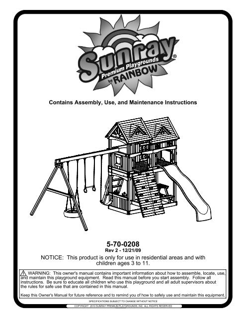
Contains Assembly, Use, and Maintenance Instructions<br />
5-70-0208<br />
Rev 2 - 12/21/09<br />
NOTICE: This product is only for use in residential areas and with<br />
children ages 3 to 11.<br />
! WARNING: This owner's manual contains important information about how to assemble, locate, use,<br />
and maintain this playground equipment. Read this manual before you start assembly. Follow all<br />
instructions. Be sure to educate all children who use this playground and all adult supervisors about<br />
the rules for safe use that are contained in this manual.<br />
Keep this Owner's Manual for future reference and to remind you of how to safely use and maintain this equipment.<br />
SPECIFICATIONS SUBJECT TO CHANGE WITHOUT NOTICE<br />
COPYRIGHT 2010 SUNRAY PREMIUM PLAYGROUNDS, INC. ALL RIGHTS RESERVED
NOTICE....IMPORTANT INFORMATION:<br />
PLEASE READ<br />
IF YOU ARE MISSING ANY PARTS,<br />
HAVE DAMAGED PARTS, OR ARE<br />
HAVING TROUBLE ASSEMBLING<br />
THIS PRODUCT, PLEASE CALL<br />
SUNRAY PREMIUM PLAYGROUNDS<br />
CUSTOMER SERVICE CENTER<br />
AT 1-888-825-2006<br />
or<br />
E-Mail:<br />
customerservice@sunraypremiumplygrounds.com<br />
Website: www.sunraypremiumplaygrounds.com<br />
CUSTOMER SERVICE HOURS:<br />
MONDAY - FRIDAY 8am - 5pm cst<br />
SATURDAYS (April 17 - June 26) 8:30am - 5pm cst<br />
STOP<br />
PLEASE CONTACT SUNRAY PREMIUM<br />
PLAYGROUNDS, INC. CUSTOMER SERVICE AT<br />
1-888-825-2006 WITH ANY ISSUES SUCH AS:<br />
PART PROBLEMS, ASSEMBLY ISSUES, OR<br />
GENERAL ASSISTANCE.<br />
1
OWNER'S MANUAL<br />
Sunray Premium Playgrounds, Inc.<br />
Thank you for choosing Sunray Premium Playgrounds, Inc. Please read<br />
the instruction manual thoroughly before you start building your Sunray<br />
Premium Playground, Inc. playground to help ensure safe installation.<br />
Familiarize yourself with all hardware and <strong>parts</strong> to help with building your<br />
playground. Make sure to send in your owner's registration card on the<br />
back cover in order to validate your warranty.<br />
WARNING: Failure to follow the assembly, location, use, and<br />
maintenance instructions in this manual could result<br />
in serious injury to children using this playground.<br />
Rules for Safe Play..........................................................................3<br />
Choosing Location of Play System..................................................4<br />
Choosing Proper Surface Material...................................................4-5<br />
Maintenance....................................................................................5-6<br />
Installation Hints..............................................................................6<br />
Commonly Asked Questions...........................................................7<br />
Tools Required for Assembly..........................................................10<br />
Hardware.........................................................................................10-12<br />
Parts Identification...........................................................................13-18<br />
Instructions......................................................................................19-61<br />
Warranty Procedure........................................................................62<br />
Warranty..........................................................................................63-64<br />
Registration Card...................................................................Back Cover<br />
2
100% PURE FSC-COC-FM CERTIFIED CHINESE C. Lanceolata Lumber. FSC-CoC-FM means that<br />
from the Forest to your back yard the lumber is Certified to have been taken care of in a<br />
Scientifically and Socially accepted manner so you can rest assured the Lumber is sustainable and<br />
harvested in accordance to all laws.<br />
THE WOODEN COMPONENTS IN YOUR SUNRAY PREMIUM PLAYGROUND ARE MANUFACTURED<br />
FROM 100% PURE FSC-CoC-FM CERTIFIED CHINESE C. Lanceolata lumber. THIS HIGH QUALITY<br />
LUMBER IS naturally rot resistant, machines smoothly, and takes a stain to leave a beautiful<br />
natural look.<br />
Safety Instructions<br />
Rules for Safe Play<br />
WARNING: Before allowing children to play on this equipment for the first time,<br />
carefully review the rules for safe play with them. Observing the following<br />
statements and warnings reduces the likelihood of a serious or fatal injury.<br />
1. IT IS RECOMMENDED that no more than 8 children, not exceeding a combined weight of 1,000 pounds, play<br />
on the system at one time. This product is recommended for children 3 to 11 years of age.<br />
2. CLOSE ADULT SUPERVISION is required, especially for younger children.<br />
3. WARN CHILDREN TO AVOID playing or walking in front of, behind, or between moving equipment.<br />
4. WARN CHILDREN NOT TO twist swing chains or ropes, or to loop them over the top support bar since this<br />
may reduce the strength of the chain or rope.<br />
5. INSTRUCT CHILDREN NOT TO swing empty seats or trapeze bar.<br />
6. INSTRUCT CHILDREN to always sit, never stand or kneel, in the center of the swing seat with their full weight.<br />
7. INSTRUCT CHILDREN NOT TO use any part of the play system in a manner other than what it is intended.<br />
8. INSTRUCT CHILDREN NOT TO get off equipment while it is in motion.<br />
9. DRESS CHILDREN APPROPRIATELY. CHILDREN SHOULD NOT wear scarves, hats with straps, helmets,<br />
jackets with draw strings, hooded jackets, poorly fitting shoes, or any other loose fitting clothing which could<br />
become entangled or snagged on equipment.<br />
10. INSTRUCT CHILDREN NOT TO play on the equipment if it is wet. Potentially slippery surfaces may cause a<br />
hazard.<br />
11. VERIFY all suspended items such as ropes and chains are secure at both ends.<br />
12. VERIFY all suspended items such as climbing ropes are tight so they cannot be looped back on themselves.<br />
13. INSTRUCT CHILDREN NOT TO attach items to the play system not specifically intended for use with the<br />
play equipment. Items such as, but not limited to, jump ropes, clotheslines, and pet leashes may pose a<br />
strangulation hazard.<br />
14. INSTRUCT CHILDREN TO REMOVE any bike or other sports helmets before playing on the play equipment, as<br />
they may pose a possible hanging hazard. Children must be dressed appropriately.<br />
15. INSTRUCT CHILDREN there may only be one person on a swing at a time with a maximum weight of 150<br />
pounds per swing.<br />
16. VERIFY there are no gaps between the slide bed way and the slide screws.<br />
17. INSTRUCT CHILDREN to always go down slides feet first. Never slide head first.<br />
18. INSTRUCT CHILDREN TO NEVER climb, crawl, or walk on items not intended for such use. Such types of play<br />
on top of Monkey Bars, Fort Roof, and Swingbeams greatly increase the risk of a serious or fatal fall.<br />
3
Choosing a location & protective surface for your play system<br />
When selecting your play site, always keep the child's safety in mind. Guidelines have been established by USCPSC that will help you<br />
achieve a safe play area:<br />
X3.1 Select Protective Surfacing - One of the most important things you can do to reduce the likelihood of serious head injuries is to install<br />
shock-absorbing protective surfacing under and around your play equipment. The protective surfacing should be applied to a depth that is<br />
suitable for the equipment height in accordance with ASTM Specification F 1292. There are different types of surfacing to choose from;<br />
whichever product you select, follow these guidelines:<br />
X3.1.1 Loose-Fill Materials:<br />
X3.1.1.1 Maintain a minimum depth of 9 inches of loose-fill materials such as wood mulch/chips, engineered wood fiber (EWF), or<br />
shredded/recycled rubber mulch for equipment up to 8 feet high; and 9 inches of sand or pea gravel for equipment up to 5 feet high. NOTE:<br />
An initial fill level of 12 inches will compress to about a 9-inch depth of surfacing over time. The surfacing will also compact, displace, and<br />
settle, and should be periodically refilled to maintain at least a 9-inch depth.<br />
X3.1.2 Use a minimum of 6 inches of protective surfacing for play equipment less than 4 feet in height. If maintained properly, this should be<br />
adequate. (At depths less than 6 inches, the protective material is too easily displaced or compacted.) NOTE: Do not install home<br />
playground equipment over concrete, asphalt, or any other hard surface. A fall onto a hard surface can result in serious injury to the<br />
equipment user. Grass and dirt are not considered protective surfacing because wear and environmental factors can reduce their shock<br />
absorbing effectiveness. Carpeting and thin mats are generally not adequate protective surfacing. Ground level equipment - such as a<br />
sandbox, activity wall, playhouse or other equipment that has no elevated play surface - does not need any protective surfacing.<br />
X3.1.3 Use containment, such as digging out around the perimeter and/or lining the perimeter with landscape edging. Don't forget to<br />
account for water drainage.<br />
X3.1.3.1 Check and maintain the depth of the loose-fill surfacing material. To maintain the right amount of loose-fill materials, mark the<br />
correct level on play equipment support posts. That way you can easily see when to replenish and/or redistribute the surfacing.<br />
X3.1.3.2 Do not install loose fill surfacing over hard surfaces such as concrete or asphalt.<br />
X3.1.4 Poured-In-Place Surfaces or Pre-Manufactured Rubber Tiles - You may be interested in using surfacing other than loose-fill materials<br />
- like rubber tiles or poured-in-place surfaces.<br />
X3.1.4.1 Installations of these surfaces generally require a professional and are not “do-it-yourself” projects.<br />
X3.1.4.2 Review surface specifications before purchasing this type of surfacing. Ask the installer/manufacturer for a report<br />
showing that the product has been tested to the following safety standard: ASTM F1292 Standard Specification for Impact<br />
Attenuation of Surfacing Materials within the Use Zone of Playground Equipment. This report should show the specific height<br />
for which the surface is intended to protect against serious head injury. This height should be equal to or greater than the fall<br />
height – vertical distance between a designated play surface (elevated surface for standing, sitting, or climbing) and the<br />
protective surfacing below – of your play equipment.<br />
X3.1.4.3 Check the protective surfacing frequently for wear.<br />
X3.1.5 Placement—Proper placement and maintenance of protective surfacing is essential. Be sure to:<br />
X3.1.5.1 Extend surfacing at least 6 feet from the equipment in all directions.<br />
X3.1.5.2 For to-fro swings, extend protective surfacing in front of and behind the swing to a distance equal to twice the<br />
height of the top bar from which the swing is suspended.<br />
X3.1.5.3 For tire swings, extend surfacing in a circle whose radius is equal to the height of the suspending chain or rope,<br />
plus 6 feet in all directions.<br />
Supplemental<br />
1. The play system should be located on solid level ground free of objects that could cause injury such as, but not limited to, tree stumps,<br />
roots, and large rocks. Stationary components such as ladders and slides must be no less than SIX FEET (1.8 meters) from any<br />
structure or obstruction such as a fence, garage, house, tree or overhanging branches, electrical wires or clotheslines. Any swinging<br />
equipment must be a minimum distance of TWICE the height of the swing<br />
beam away from any structures or obstructions as specified above. We<br />
also recommend that you do not install your play system near a lake, river,<br />
swimming pool or other water hazards.<br />
2. Locate slide out of direct sunlight to reduce the likelihood of serious burns.<br />
A slide that faces north will receive the least direct sunlight.<br />
3. It is recommended not to place a set on sandy soil or loose fill as it may<br />
require additional anchoring in that situation.<br />
4. If anchoring your play system, all underground utilities must be located in<br />
play zone before starting assembly of play system.<br />
9.5' min<br />
30' 6' min.<br />
6' min.<br />
Set Dimensions Play Zone<br />
L 17' x W 14 1/2' x H 11' L 29' x W 30'<br />
4<br />
29'<br />
6' min.
Maximum Fall Height is 8'<br />
TABLE 3.1 Fall Height in Feet From Which a Life Threatening Head Injury Would Not Be Expected<br />
Type of Material 6 in. depth 9 in. depth 12 in. depth<br />
Double Shredded Bark Mulch 6 ft. 10 ft. 11 ft.<br />
Wood Chips 6 ft. 7 ft. 12 ft.<br />
Fine Sand 5 ft. 5 ft. 9 ft.<br />
Fine Gravel 6 ft. 7 ft. 10 ft.<br />
Surfacing in "compressed" depths - See CPS & ASTM for Fall Heights of equipment<br />
Equipment Fall Height 1' 2' 3' 4' 5' 6' 7' 8' 9' 10' 11' 12'<br />
Wood Chips 6" 6" 6" 6" 6" 6" 6 1/2" 7 1/2" 8 1/4" 9" 12" 13"<br />
Double Shredded Bark Mulch 6" 6" 6" 6" 7" 8" 9" 9 3/4" 10 1/2" 11 1/2" 12" 13"<br />
Engineered Wood Fibers 6" 6" 6" 7" 8 1/2" 9" 9 1/2" 10 1/4" 10 3/4" 11" 10 3/4" 12"<br />
Fine Sand 6" 6" 6 1/2" 8" 9 10" 10 1/2" 11 1/4" 12" 13 1/2" 14 3/4" 16"<br />
Coarse Sand 6" 6" 7 1/2" 9" 10 1/2" 12" 14" 16" 18" 20" 22" 24"<br />
Fine Gravel 6" 6" 6" 6 3/4" 8" 9" 10" 10 3/4" 11 1/2" 12" 13 1/4" 14 1/2"<br />
Medium Gravel 6" 6 1/4" 8" 9" 9" 12" 14" 16" 18" 20" 22" 24"<br />
Chart obtained from U.S. Consumer Product Safety Commission Handbook for Public Playground Safety<br />
Assembly safety<br />
1. Wear safety glasses to protect your eyes from flying wood chips when drilling or cutting.<br />
2. Verify that all bolts and screws are secured tightly and all acorn nuts are snug (acorn nuts should be<br />
tightened to 5 foot pounds of torque).<br />
3. DO NOT allow children to play on the play system until it is completely assembled in a proper location.<br />
4. DO NOT allow children in the area while you are assembling your play system. Many of the Sunray Premium<br />
Playgrounds, Inc. components are very heavy and could seriously injure a child.<br />
Maintenance of your play system<br />
To ensure safe enjoyment of your Sunray Premium Playgrounds play system for years to come, follow<br />
these maintenance tips:<br />
1. At the beginning and end of each usage season and twice each month, check and tighten as needed (but do<br />
not over tighten causing wood to crack) all nuts and bolts. Acorn nuts should be tightened to 5 foot pounds of<br />
torque. Hardware used on swinging elements should be checked at least twice a month to ensure proper<br />
fastening.<br />
2. At the beginning and end of each usage season and twice each month, check all coverings for bolts and<br />
sharp edges to be certain they are in place. Replace when necessary.<br />
3. Oil all metallic moving <strong>parts</strong> monthly during the usage period.<br />
4. At the beginning of each usage season and once a month durning the play season, check all moving <strong>parts</strong><br />
including swing seats, ropes, and chains for wear, rust, or other deterioration and replace as needed.<br />
5. At the beginning of each usage season, check all metal <strong>parts</strong> for rust. If needed, sand and repaint using a<br />
nonlead-based paint meeting the requirements of Title 16 CFR Part 1303.<br />
6. At the beginning of each usage season, check all wood members for deterioration and splinters. Spot sand<br />
any areas that are checking or splintering. If <strong>parts</strong> are deteriorating, replace as needed.<br />
7. Remove plastic swing seats, half bucket swing and take indoors or do not use when temperature drops below<br />
36 Fahrenheit. Reinstall all plastic <strong>parts</strong> that were removed for the cold season.<br />
8. Check, twice a month, the depth of loose fill protective surfacing materials to prevent compaction<br />
and to maintain appropriate depth. Rake or replace as necessary.<br />
5
9. Check the C-Links on the chain to ensure they are securely closed. Tighten with a crescent wrench as<br />
needed.<br />
10. On a yearly basis, we recommend that you coat your play system with a sealant or preservative. You may<br />
also want to spot sand areas before sealing. Be sure that the sealant you select is non-toxic and child safe.<br />
11. When you are ready to dispose of your playset, make sure all metal, plastic and wood components are<br />
disposed of in accordance with local waste ordinances and ensure that no unreasonable hazards exist.<br />
PILOT<br />
HOLES<br />
Helpful Installation Hints<br />
*NOTE: Refer to these assembly tips throughout the entire installation process.<br />
1. After thoroughly reading all information and properly locating your play system site, carefully<br />
unpack <strong>parts</strong>. As you unpack your play system, keep the <strong>parts</strong> list handy and become familiar with each<br />
part before beginning assembly. Remember that a little extra time spent familiarizing yourself with the <strong>parts</strong><br />
and instructions before you begin will help avoid mistakes and save you time later.<br />
2. Group both wood and non-wood <strong>parts</strong> together in accordance to each page, or Step, of this assembly<br />
manual. Doing this now will help you quickly locate <strong>parts</strong> and assemble the set with ease.<br />
3. Sort your hardware into groups of similar hardware pieces. Use a solid surface, such as the empty boxes,<br />
to ensure you do not lose any hardware.<br />
4. Before starting each Step, thoroughly read all of the instructions to ensure all information is understood.<br />
Pay special attention to the orientation of each part, details & notes, and proper usage of hardware. Each<br />
piece of hardware is required for a certain part of the assembly.<br />
5. Certain Steps of the assembly are best performed on a hard flat surface to ensure proper and accurate<br />
assembly.<br />
6. All Lag Bolts must have pre-drilled holes 2" deep (as shown in Detail A). Use a 1/8" drill bit for all<br />
1/4" and 5/16" Lag Bolts and use a 1/4" drill bit for all 3/8" Lag Bolts. Lag Bolts can be difficult to put<br />
in knot holes. Pre-drilling pilot holes will help to prevent the Lag Bolts from breaking. Refer to<br />
"Commonly Asked Questions" on page 7 for more information about Lag Bolts.<br />
7. All #14 Phillips Pan Head Tap Screws must have pre-drilled holes 1/2" deep. Use a 1/8" drill bit.<br />
8. Use a clamp to secure Facias flush to the Uprights and use holes in facia as a guide for placing Lag<br />
Bolt Pilot Holes (as shown in Detail B).<br />
9. Verify Facias are flush with Uprights.<br />
10. Check assembly periodically to ensure the set is level and all facias are square to the uprights.<br />
11. If a gap occurs between boards when inserting Screws or Lag Bolts, back out hardware and apply<br />
pressure to the top board while reinserting hardware in the same hole.<br />
DETAIL A<br />
USE FACIA AS<br />
A GUIDE FOR<br />
PRE-DRILLING<br />
HOLES<br />
6<br />
EDGES FLUSH<br />
DETAIL B
COMMONLY ASKED QUESTIONS<br />
Question: How do I know when Lag Bolts and other Fasteners are tightened properly?<br />
Answer: Lag Bolts and other Fasteners are tight when the head of the Lag Bolt and Washer<br />
are firmly compressed against the wood. If splintering occurs, that is an indication you<br />
are over tightening the Lag Bolts and other Fasteners. (Splintering is when the wood<br />
fibers fracture out from under the washers).<br />
Question: What should I do if a Lag Bolt or other Fastener lines up with a knot, or if the Lag Bolt<br />
breaks?<br />
Answer: There is extra Hardware provided with the set for this reason. Re-Drill a new hole with<br />
a 1/8" Drill Bit in a new direction to miss the obstruction.<br />
Question: What if my Play System is leaning and/or rocks?<br />
Answer: This is caused by unleveled ground under the Base and Support Wings of the Play<br />
System. It may be necessary to remove or add some soil beneath the Play System<br />
to make it level. Ground Stakes, when installed, will also provide stability.<br />
Question: What if my Play System has cracks on the wood or seems to be developing cracks?<br />
Answer: Seasonal checks, surface cracks, and knot holes are natural characteristics of all<br />
wooden play equipment. A check is a separation of the wood fibers running with the<br />
grain. This is caused by varying temperature and moisture conditions. By coating<br />
your Play System annually with a sealant or preservative, you can help protect your<br />
Play System from developing (not stopping) seasonal checks. Please remember to<br />
follow all installation instructions, including installing the play set on solid level ground.<br />
Question: What is the sticky substance that appears on the wood?<br />
Answer: The sticky substance that may appear on the wood is called pitch. It is common for<br />
the lumber to have occasional pitch seepage which does not affect the structural<br />
integrity of the part. Pitch provides the natural rot resistant characteristics of the<br />
lumber. If play surfaces or play items become overly sticky with pitch use rubbing<br />
alcohol to safely remove.<br />
Question: What accessories may be added or what modifications can be made to my Sunray<br />
Premium Playground, Inc. set?<br />
Answer: Sunray Premium Playground, Inc. playsets are complete kits and are not modular.<br />
Playsets with unauthorized accessories or modifications will not be covered under<br />
warranty. Non-residential use of the playset voids warranty.<br />
Question: Is my child old enough to use all play items on my set?<br />
Answer: All play items on Sunray Premium Playground, Inc.<br />
playsets are designed for children ages 3 to 11, but it is<br />
the end users responsibility to determine suitability of<br />
use by their children for each play item.<br />
7<br />
EXAMPLE OF SEASONAL<br />
CHECKS OR SURFACE<br />
CRACKS
PARTS IDENTIFICATION<br />
77<br />
78<br />
82<br />
81<br />
86<br />
16<br />
19<br />
20<br />
19<br />
10<br />
12<br />
11<br />
72<br />
99<br />
46<br />
69<br />
98<br />
75<br />
73<br />
68<br />
57<br />
55<br />
54<br />
58<br />
13<br />
88<br />
87<br />
75<br />
113<br />
83<br />
74<br />
114<br />
49<br />
7<br />
9<br />
8<br />
2<br />
5<br />
38<br />
1<br />
15<br />
17<br />
6<br />
66<br />
64<br />
116<br />
118<br />
56<br />
105<br />
89<br />
16<br />
8
PARTS IDENTIFICATION<br />
17<br />
35<br />
34 33<br />
15<br />
19<br />
20<br />
32 31<br />
30<br />
29<br />
64<br />
17<br />
71<br />
103<br />
3<br />
121<br />
49<br />
68<br />
75<br />
9<br />
69<br />
104<br />
52<br />
73<br />
84<br />
73<br />
70<br />
39<br />
4<br />
68<br />
85
*NOTE: Extra hardware is included in the hardware bags. Not all hardware will be used<br />
during installation.<br />
TOOLS REQUIRED FOR ASSEMBLY<br />
Tape Measure<br />
Carpenters Level<br />
Carpenters Square<br />
Claw Hammer<br />
Wood Clamp<br />
Standard or Cordless Drill<br />
with #2 & #3 Phillips Bits<br />
Electric Impact Gun or 1/4"<br />
and 3/8" Ratchet<br />
Torque Wrench<br />
Sunray Hardware List<br />
F/N# DESCRIPTION DIMENSION QTY<br />
H1 Flat Washer 1/4" 116<br />
H3 Flat Washer 3/8" 35<br />
H4 Flat Washer 1/2" 9<br />
H7 SAE Washer 1/4" 28<br />
H9 Lock Washer 1/4" 8<br />
H11 Lock Washer 3/8" 36<br />
H17 Standard Nut 3/8" 10<br />
H24 Nylock Nut 3/8" 12<br />
H28 Acorn Nut 3/8" 22<br />
H30 Round Pallet Nut 3/8" 12<br />
H32 4 Prong T-Nut 1/4" 44<br />
H34 4 Prong T-Nut 3/8" 4<br />
H50 Carriage Bolt 3/8" x 3 1/2" 2<br />
H55 Carriage Bolt 3/8" x 6" 2<br />
H56 Carriage Bolt 3/8" x 6 1/2" 4<br />
H60 Carriage Bolt 3/8" x 8 1/2" 1<br />
H93 Lag Bolt 1/4" x 2" 6<br />
H100 Lag Bolt 1/4" x 4 1/2" 4<br />
H108 Lag Bolt 5/16" x 3" 106<br />
H116 Lag Bolt 3/8" x 3 1/2" 2<br />
H146 Hex Bolt 1/4" x 2 1/4" 8<br />
H124 Hex Bolt 3/8" x 1 1/2" 2<br />
H130 Hex Bolt 3/8" x 4" 6<br />
H135 Hex Bolt 3/8" x 6 1/2" 12<br />
H139 Hex Bolt 3/8" x 9" 1<br />
H184 Hex Bolt 3/8" x 2 1/2" 2<br />
H176 Phillips Wood Screw #8 x 1" 335<br />
H152 Phillips Wood Screw #8 x 1 1/2" 500<br />
H154 Phillips Wood Screw #8 x 2" 58<br />
H155 Phillips Wood Screw #8 x 2 1/2" 50<br />
H158 Phillips Pan Head Tap Screw #10 x 1 1/2" 2<br />
H163 Phillips Pan Head Tap Screw #14 x 3/4" 6<br />
H164 Phillips Pan Head Tap Screw #14 x 1" 26<br />
H166 Phillips Pan Head Tap Screw #14 x 1 1/2" 8<br />
H170 Phillips Pan Head Machine Screw 1/4" x 1 1/4" 36<br />
10<br />
1/8" Drill Bit<br />
1/4" Drill Bit<br />
7/16" Drill Bit<br />
Crescent Wrench<br />
7/16" Deep Well Socket<br />
1/2" Deep Well Socket<br />
9/16" Deep Well Socket<br />
Locking Pliers<br />
8' Step Ladder<br />
Safety Glasses<br />
Adult Helper
H93<br />
*NOTE: Hardware is drawn to actual size except for H139 on page12<br />
*NOTE: Not all Hardware is pictured.<br />
H100<br />
H108<br />
H163<br />
H176<br />
H164<br />
H152<br />
H158<br />
H166<br />
H116<br />
Hardware for Assembly<br />
H154<br />
H1<br />
H3<br />
H155<br />
H4<br />
H9<br />
H11<br />
H7<br />
11<br />
H17<br />
H28<br />
H24<br />
H32<br />
H34<br />
H30<br />
H170<br />
0<br />
1<br />
2<br />
3<br />
4<br />
5<br />
6<br />
7<br />
8<br />
9
H60<br />
Hardware for Assembly<br />
*NOTE: Thread length may vary from what is pictured.<br />
H56<br />
H124<br />
H55<br />
H50<br />
H184<br />
12<br />
H146<br />
H130<br />
H135<br />
H139 is 3/8" x 9"<br />
H139<br />
0<br />
1<br />
2<br />
3<br />
4<br />
5<br />
6<br />
7<br />
8<br />
9
1<br />
3<br />
5<br />
7<br />
9<br />
11<br />
13<br />
15<br />
17<br />
19<br />
3@ 5/8" x 3" x 38" Deck Board<br />
18@ 5/8" x 3 1/4" x 26 1/2" Rail Upright<br />
1@ 5/8" x 1 9/16" x 36 1/2" Top Rock Wall Board<br />
6@ 5/8" x 3 1/4" x 36 1/2" Rock Wall Board<br />
1@ 5/8" x 3 1/4" x 36 1/2" RW Board w/Rope Hole<br />
2@ 5/8" x 3 1/4" x 16" Fan Vertical<br />
6@ 5/8" x 3 1/4" x 36" Table Board<br />
20@ 5/8" x 3 3/8" x 43 3/8" Roof Board<br />
4@ 5/8" x 3 1/4" x 49 7/8" Lower Roof Frame<br />
4@ 5/8" x 3 1/4" x 43 13/16" Upper Roof Frame<br />
22 23<br />
2@ 5/8" x 3 3/8" x 4 1/8"<br />
Right Dormer Board<br />
24 25<br />
2@ 5/8" x 3 3/8" x 8 1/8"<br />
Right Dormer Board<br />
26 27<br />
2@ 5/8" x 3 3/8" x 12 3/16"<br />
Right Dormer Board<br />
28 29<br />
30<br />
2@ 5/8" x 3 3/8" x 16 1/4"<br />
Right Dormer Board<br />
2@ 5/8" x 3 3/8" x 6 1/8"<br />
Left Dormer Board<br />
32<br />
2@ 5/8" x 3 3/8" x 10 1/8"<br />
Left Dormer Board<br />
PARTS IDENTIFICATION<br />
13<br />
2<br />
4<br />
6<br />
8<br />
10<br />
12<br />
14<br />
16<br />
18<br />
20<br />
20@ 5/8" x 3 1/4" x 44" Deck Board<br />
10@ 5/8" x 3 1/4" x 20" Store Front Upright<br />
6@ 5/8" x 3 1/4" x 36 1/2" Inside 2 Hole RW Board<br />
6@ 5/8" x 3 1/4" x 36 1/2" 2 Hole RW Board<br />
2@ 5/8" x 3 1/4" x 36" Fan Horizontal<br />
4@ 5/8" x 3 1/4" x 11 1/8" Fan Ray<br />
4@ 5/8" x 3 1/4" x 26" Roof Runner<br />
8@ 5/8" x 3 1/4" x 35 3/4" Roof Frame Side<br />
2@ 5/8" x 3 1/4" x 9" Roof Brace<br />
20@ 5/8" x 3 3/8" x 37 5/16" Roof Board<br />
2@ 5/8" x 3 3/8" x 6 1/8"<br />
Right Dormer Board<br />
2@ 5/8" x 3 3/8" x 10 1/8"<br />
Right Dormer Board<br />
2@ 5/8" x 3 3/8" x 14 3/16"<br />
Right Dormer Board<br />
2@ 5/8" x 3 3/8" x 4 1/8"<br />
Left Dormer Board<br />
31<br />
2@ 5/8" x 3 3/8" x 8 1/8"<br />
Left Dormer Board<br />
33<br />
2@ 5/8" x 3 3/8" x 12 3/16"<br />
Left Dormer Board
34 35<br />
2@ 5/8" x 3 3/8" x 14 3/16"<br />
Left Dormer Board<br />
36<br />
89<br />
93<br />
95<br />
99<br />
101<br />
38<br />
39<br />
41<br />
43<br />
46<br />
2@ 5/8" x 2 1/4" x 8 3/4" Dormer Fan Vertical<br />
10@ 5/8" x 3 1/4" x 17" Rail Upright<br />
7@ 5/8" x 1 1/4" x 13" Window Horizontal<br />
6@ 5/8" x 2" x 15 1/8" Window Upright<br />
3@ 5/8" x 3 1/4" x 13 3/8" Arched Window Trim<br />
2@ 5/8" x 1 1/4" x 17" Window Vertical<br />
2@ 5/8" x 4 3/4" x 44" Deck Board<br />
1@ 5/8" x 5 1/4" x 20" Store Front Upright<br />
2@ 5/8" x 4 1/2" x 49 7/8" Roof Frame Top<br />
2@ 5/8" x 4 1/2" x 43 13/16" Roof Frame Bottom<br />
4@ 1 1/4" x 3 1/4" x 44" 2 Hole Facia<br />
37<br />
107<br />
103 104<br />
90<br />
92<br />
94<br />
98<br />
40<br />
42<br />
44<br />
2@ 5/8" x 3 3/8" x 16 1/4"<br />
Left Dormer Board<br />
2@ 5/8" x 2 1/4" x 22" Dormer Fan Horizontal<br />
8@ 5/8" x 3 1/4" x 11 1/2" Cabin Upright<br />
3@ 5/8" x 1 1/4" x 15 1/8" Window Vertical<br />
4@ 5/8" x 1 1/4" x 11 1/2" Window Vertical<br />
3@ 5/8" x 3 1/4" x 13 3/8" Window Trim Board<br />
100<br />
4@ 5/8" x 3 1/4" x 16 1/4" Bubble Panel Frame<br />
119 120<br />
2@ 5/8" x 3 1/4" x 26 1/2" Notched Rail Upright<br />
2@ 5/8" x 3 1/4" x 26 1/2" Rail Upright w/Holes<br />
105<br />
109<br />
1@ 5/8" x 4 3/4" x 44" Arched Angled Facia<br />
1@ 5/8" x 5 1/4" x 17" Rail Upright<br />
1@ 5/8" x 5 1/4" x 6 1/2" Rail Upright<br />
PARTS IDENTIFICATION<br />
106<br />
1@ 5/8" x 5 1/4" x 10" Rail Upright<br />
8@ 5/8" x 4 1/4" x 26 1/8" Roof Frame Side<br />
2@ 5/8" x 4 1/2" x 49 7/8" Roof Frame Bottom<br />
2@ 5/8" x 4 1/2" x 43 13/16" Roof Frame Top<br />
1@ 5/8" x 4 3/4" x 44" Arched Facia<br />
2@ 5/8" x 5 1/4" x 11 1/2" Cabin Upright<br />
113<br />
3@ 1 1/4" x 3 1/4" x 9 1/2" Corner Facia<br />
121<br />
1@ 1 1/4" x 3 1/4" x 50" Side Facia<br />
14
50<br />
51<br />
52<br />
54<br />
56<br />
58<br />
60<br />
63<br />
65<br />
66<br />
111<br />
115<br />
67<br />
68<br />
1@ 1 1/4" x 3 1/4" x 61" Rock Wall Runner<br />
1@ 1 1/4" x 3 1/4" x 83" Deck Runner<br />
1@ 1 1/4" x 3 1/4" x 24" Ladder Entrapment Board<br />
2@ 1 1/4" x 3 1/4" x 30" Left Picnic Table Leg<br />
2@ 1 1/4" x 3 1/4" x 18 3/4" Table Brace<br />
2@ 1 1/4" x 3 1/4" x 19" Table Support<br />
2@ 1 1/4" x 2 1/4" x 20 1/8" Dormer<br />
Right Support<br />
3@ 1 1/4" x 3 1/4" x 34 3/4" Left Roof Support<br />
2@ 1 1/4" x 3 1/4" x 34 3/4" Roof Support<br />
2@ 1 1/4" x 3 1/4" x 62 3/8" Rock Wall Leg<br />
1@ 1 1/2" x 1 1/2" x 37 7/8" Ship's<br />
Wheel Board<br />
2@ 1 1/4" x 3 1/4" x 17" TTT Board<br />
2@ 1 1/4" x 5 1/4" x 84" Main Beam<br />
4@ 1 1/4" x 5 1/4" x 84" 6 Hole Facia<br />
PARTS IDENTIFICATION<br />
114 49<br />
1@ 1 1/4" x 3 1/4" x 16" Center Facia<br />
53<br />
55<br />
57<br />
59<br />
61<br />
64<br />
62<br />
112<br />
15<br />
6@ 1 1/4" x 3 1/4" x 25 1/2" Rail Uprights<br />
w/Handle Holes<br />
1@ 1 1/4" x 3 1/4" x 19" Table Runner<br />
2@ 1 1/4" x 3 1/4" x 30" Right Picnic Table Leg<br />
2@ 1 1/4" x 3 1/4" x 45" Seat Support<br />
2@ 1 1/4" x 2 1/4" x 20 1/8" Dormer Left Support<br />
4@ 1 1/4" x 3 1/4" x 16 1/2"<br />
Dormer Runner<br />
3@ 1 1/4" x 3 1/4" x 34 3/4" Right Roof Support<br />
2@ 1 1/4" x 3 1/2" x 4"<br />
Fan Center<br />
2@ 1 1/4" x 2" x 43 1/2" 2 Hole Facia
69 73<br />
70 72<br />
71<br />
116<br />
74<br />
75<br />
77<br />
80<br />
83<br />
84<br />
85<br />
86<br />
87<br />
2@ 1 1/4" x 5 1/4" x 44" Deck Facia 3@ 1 1/4" x 5 1/4" x 44" 4 Hole Facia<br />
4@ 1 1/4" x 5 1/4" x 21" Ladder Step 2@ 1 1/4" x 5 1/4" x 8" Fan Center<br />
1@ 1 1/4" x 5 1/4" x 84" Single Arched Facia<br />
2@ 3" x 3" x 104" Corner Upright w/TJ Holes<br />
4@ 3" x 3" x 97 1/2" Corner Upright<br />
2@ 3" x 3" x 104" A-Frame Leg<br />
78 79<br />
1@ 3" x 3" x 60" A-Frame Cross Member<br />
1@ 3 3/8" x 3 3/8" x 44" Top Joist w/Swing Holes<br />
118<br />
1@ 1 1/4" x 4 3/4" x 43 3/4" Angled Facia<br />
8@ 2 1/2" x 2 1/2" x<br />
14 1/2" Angled Brace<br />
81<br />
1@ 1 5/8" x 5 1/4" x 84" Double Arched Facia<br />
1@ 2 1/2" x 3 1/2" x 64 9/16" Left Ladder Leg<br />
1@ 3" x 3" x 15"<br />
Upper A-Frame Bracket<br />
1@ 2 1/2" x 3 1/2" x 64 9/16" Right Ladder Leg<br />
1@ 3" x 5 1/4" x 110" 3 Position Swingbeam<br />
2@ 15/16" x 3 1/4" x 36" Seat Board<br />
2@ 15/16" x 5 1/4" x 38 1/4" Window Top/Bottom<br />
PARTS IDENTIFICATION<br />
16<br />
88<br />
82<br />
1@ 3" x 3" x 15" Lower<br />
A-Frame Bracket<br />
2@ 15/16" x 5 1/4" x 36" Seat Board
N20<br />
N6<br />
2@ Ladder Handle - Yellow<br />
N9 N8<br />
4@ Rockwall/Ladder<br />
Bracket - Brown<br />
N10<br />
N19<br />
N5<br />
6@ Safety Handle -<br />
Yellow<br />
8@ 90 Bracket - Brown<br />
N172 N173 N174<br />
N170<br />
9@ Tic Tac Toe<br />
Cylinder<br />
1@ 45 Bracket - Yellow<br />
3@ Ship's Wheel w/Cap<br />
PARTS IDENTIFICATION<br />
2@ Tic Tac Toe<br />
Insert<br />
1@ Swingbeam Plate - Brown<br />
1@ Telescope<br />
17<br />
N171<br />
N21<br />
N28<br />
N42<br />
12@ Rock<br />
2@ 90 Swingbeam<br />
Bracket - Brown<br />
3@ Tic Tac Toe<br />
Rod<br />
6@ Rebar Stake<br />
1@ Plaque
N29 N73<br />
N18 N14<br />
14@ 3/8" 2@ Small<br />
Bolt Cup Bolt Cup<br />
1@ Trapeze Bar - Yellow<br />
2@ Trapeze Rings - Yellow<br />
N17<br />
1@ Half Bucket Swing<br />
designed for ages 3-5<br />
N15<br />
N27 N30 N31<br />
N13<br />
N12<br />
4@ Short Chain - Yellow<br />
2@ Swing Seat - Blue<br />
N26<br />
6@ Swing Hanger<br />
6@ Spring Clip 12@ Wide Jaw C-Link 4@ Pear Quick Link<br />
8@ Long Chain - Yellow<br />
PARTS IDENTIFICATION<br />
18<br />
N1<br />
N24<br />
N167<br />
N168<br />
N169<br />
Parts Not Shown<br />
1@ 12' Rope - 3/4" DIA<br />
1@ Double Wall Wave Slide - Yellow<br />
1@ Chalkboard w/Chalk and Eraser<br />
1@ Small Bubble Panel<br />
1@ 4 Hole Tire
Step 1<br />
Picnic Table Assembly<br />
*SUGGESTION: Make sure to open all Hardware bags and sort Hardware before starting<br />
assembly.<br />
*SUGGESTION: Sort all components and make sure the quantities match what is in the<br />
manual before starting assembly.<br />
*NOTE: Make sure that you have a flat level surface to build the set on.<br />
1. Place Left Table Legs (54), Right Table Legs (55) and Seat Supports (57) on a hard surface and<br />
pound in T-Nuts (H32) with a hammer (as shown).<br />
*NOTE: Counter-sunk holes on Table Legs (54) (55) must be facing down.<br />
2. Line up holes on Left Table Legs (54), Right Table Legs (55), Seat Supports (57) and Table Support<br />
(58) (as shown in Detail A) and attach using 1/4" Hardware (H1) (H9) (H146) (H32).<br />
3. Stand Leg assemblies up and position Seat Boards (87) (88) on Seat Supports (57). Seat Boards<br />
(87) (88) should overhang 3 3/8" on the ends (as shown) and the edges of Seat Boards (88) and<br />
Seat Supports (57) must be flush (as shown). Attach Seat Boards (87) (88) to Seat Supports (57)<br />
using #8 Hardware (H154).<br />
4. Center Table Boards (13) on Table Supports (58) and attach using #8 Hardware (H152). There<br />
should be no gaps between Table Boards (13) when attached properly.<br />
*NOTE: Assembling Picnic Table on a hard level surface will help ensuring that the<br />
Table is square.<br />
5. Insert Screws (H154) into holes on Left Table Legs (54) and Right Table Legs (55) and attach to<br />
Table Supports (58) using #8 Hardware (H154).<br />
6. Center and attach Table Runner (53) on the bottom side of Table Boards (13) using #8 Hardware<br />
(H152).<br />
7. Position Table Braces (56) so they are centered on Seat Supports (57) and Table Runner (53) and<br />
attach using #8 Hardware (H154).<br />
19<br />
continued on next page:
Step 1<br />
continued from previous page:<br />
H146<br />
H9<br />
H32<br />
H32<br />
EDGES FLUSH<br />
57<br />
H146 H9 H1 H32<br />
58<br />
H1<br />
55<br />
H32<br />
DETAIL A<br />
3 3/8"<br />
57<br />
H154<br />
57<br />
H32<br />
54<br />
55<br />
58<br />
Picnic Table Assembly<br />
55<br />
Counter-sunk Holes<br />
Facing Down<br />
54<br />
H154<br />
54<br />
20<br />
54<br />
13<br />
H154<br />
H152<br />
56<br />
87<br />
53<br />
57<br />
88<br />
58<br />
H154<br />
55
Step 2<br />
*NOTE: Pre-drill holes for all 5/16" Lag Bolts with a 1/8" drill bit.<br />
1. Lay outside Corner Uprights (74) (75) on the ground and measure up 86" and attach Single Arched<br />
Facia (71) and Double Arched Facia (83) using 1/4" Hardware (H1) and 5/16" Hardware (H108). The<br />
ends of the Facias (71) (83) should be flush with the outside faces of the Uprights (74) (75) and the<br />
Uprights should be 84" apart from outside face to outside face.<br />
2. Attach 6 Hole Facias (68) to Corner Uprights (74) (75) using 1/4" Hardware (H1) and 5/16" Hardware<br />
(H108).<br />
*NOTE: Make sure Uprights and Facias are square before tightening Hardware.<br />
3. Center middle Corner Upright (75) between Corner Uprights (74) (75) and attach to Facias (71) (83)<br />
using 1/4" Hardware (H1) and 5/16" Hardware (H108). There should be 37 1/2" between Uprights<br />
when properly installed. Holes in Facias must be oriented as shown in Detail A.<br />
H108<br />
DETAIL A<br />
H108<br />
H1<br />
75<br />
H1<br />
68<br />
1 1/4"<br />
71<br />
37 1/2"<br />
75<br />
75<br />
84"<br />
Upright Assembly<br />
H1<br />
83<br />
21<br />
74<br />
H108<br />
75<br />
UPRIGHTS MUST<br />
BE POSITIONED<br />
AS SHOWN<br />
68<br />
74<br />
86"
H108<br />
Step 3<br />
75 1/2"<br />
75<br />
H1<br />
68<br />
73<br />
46<br />
38"<br />
H108<br />
71<br />
75<br />
H1<br />
H108 H1<br />
Upright Assembly<br />
1. Stand assemblies up and attach Top Joist w/Swing Holes (79), with counter-sunk holes down, to<br />
Corner Uprights (74) using 1/2" Hardware (H4) and 3/8" Hardware (H56) (H3) (H11) (H17) (H28).<br />
*NOTE: Pre-drill holes for all 5/16" Lag Bolts with a 1/8" drill bit.<br />
2. Attach 4 Hole Facias (73) to Corner Uprights (74) (75) using 1/4" Hardware (H1) and 5/16" Hardware<br />
(H108). Holes in Facias (68) (73) must be offset (as shown in Detail A).<br />
*SUGGESTION: When Installing Facias (73), put bottom Lag Bolts in first and check that<br />
measurements are correct and the assembly is square before inserting top Lag Bolts.<br />
3. Measure up 75 1/2" on Corner Uprights (75) and attach 2 Hole Facia (46) using 1/4" Hardware (H1)<br />
and 5/16" Hardware (H108).<br />
75<br />
68<br />
73<br />
22<br />
83<br />
75<br />
H56<br />
79<br />
73<br />
1 3/4" 1 1/4"<br />
74<br />
H4<br />
DETAIL A<br />
73<br />
H3<br />
H11<br />
H1<br />
H17<br />
H28<br />
COUNTER<br />
SUNK HOLES<br />
DOWN<br />
H108
Step 4<br />
Holes Down<br />
H108<br />
67<br />
H1<br />
74<br />
Main Beam Installation<br />
*NOTE: Pre-drill holes for all 5/16" Lag Bolts with a 1/8" drill bit.<br />
1. Measure up 57 3/8" on Corner Uprights (74) (75) and attach Main Beams (67) to Corner Uprights<br />
using 1/4" Hardware (H1) and 5/16" Hardware (H108).<br />
*NOTE: Holes in Main Beams (67) must be down when installed properly.<br />
75<br />
23<br />
75<br />
H1<br />
75<br />
67<br />
H108<br />
75<br />
57 3/8"
Step 5<br />
67<br />
Deck Assembly<br />
1. Center and evenly space Deck Boards (1) (2) (38) between Uprights and attach Deck Boards to Main<br />
Beams (67) using #8 Hardware (H152). Pre-drilled holes in Deck Boards should line up with the<br />
centers of the Main Beams (67).<br />
*NOTE: Deck Boards (1) (2) (38) must be evenly spaced, and gaps between boards must not<br />
exceed 3/16".<br />
2. Center and attach Deck Runner (51) to Deck Boards using #8 Hardware (H152).<br />
38<br />
24<br />
2<br />
51<br />
2<br />
67<br />
1<br />
H152
Step 5a<br />
H108<br />
75<br />
Deck Assembly Insert<br />
*NOTE: If Deck Boards (2) (38) DO NOT fit between Uprights (74) (75), as<br />
stated on Step 5 of the manual, follow these steps.<br />
1. Loosen 5/16" Hardware (H108) on Main Beams (67) that attach to Corner Uprights (74) (75) on<br />
sides of the set. Make sure not to completely remove the Hardware (H108) from Corner Uprights<br />
(74) (75). You may have to pull out on the Uprights to gain enough space for the Deck Boards to<br />
fit between the Uprights.<br />
2. After the Deck Boards (2) (38) are fitted between Uprights (74) (75) attach Deck Boards (1) (2) (38) to<br />
Main Beams (67) using #8 Hardware (H152) as shown in the manual.<br />
3. Tighten Hardware (H108) on Main Beams (67) that was loosened in #1.<br />
4. Continue with #2 Step 5 in the manual to complete the Deck Assembly.<br />
67<br />
24a<br />
38<br />
2<br />
74<br />
INSIDE VIEW<br />
OF SET<br />
H108
Step 6<br />
DECK BOARDS<br />
NOT SHOWN FOR<br />
CLARITY OF VIEW<br />
75<br />
80<br />
75<br />
Angled Brace Installation<br />
*NOTE: Pre-drill holes for all 5/16" Lag Bolts with a 1/8" drill bit.<br />
1. Attach Angled Braces (80) to Corner Uprights (74) (75) using 1/4" Hardware (H1) and 5/16"<br />
Hardware (H108). The tops of the Angled braces (80) should be touching the bottoms of the Deck<br />
Boards (as shown in Detail A).<br />
2. Attach Angled Braces (80) to Main Beams (67) using 1/4" Hardware (H1) and 5/16" Hardware<br />
(H108).<br />
H108<br />
67<br />
25<br />
75<br />
67<br />
H1<br />
H108<br />
74<br />
67<br />
H1<br />
DETAIL A<br />
H108<br />
1<br />
80<br />
H1<br />
80
Step 7<br />
H108 H1<br />
69<br />
121<br />
68<br />
46<br />
75<br />
113<br />
Facia Installation<br />
*NOTE: Pre-drill holes for all 5/16" Lag Bolts with a 1/8" drill bit.<br />
1. Attach Deck Facias (69) to Corner Uprights (74) (75) and Angled Braces (80) using 1/4" Hardware<br />
(H1) and 5/16" Hardware (H108). The tops of the Deck Facias (69) must be flush with the tops of the<br />
Deck Boards, and offset holes must be down when installed properly.<br />
2. Position 6 Hole Facias (68) so the tops are flush with the tops of the Deck Boards and attach to<br />
Corner Uprights using 1/4" Hardware (H1) and 5/16" Hardware (H108).<br />
*NOTE: Holes on Deck Facias (69) and 6 Hole Facias (68) must be offset as shown in Detail A.<br />
3. Position 2 Hole Facias (46), Side Facia (121) and Corner Facias (113) (in locations shown) and<br />
attach to Corner Uprights (74) (75) using 1/4" Hardware (H1) and 5/16" Hardware (H108).<br />
4. Position Center Facia (114) so it is centered on middle Corner Upright (75) and attach using 1/4"<br />
Hardware (H1) and 5/16" Hardware (H108).<br />
113<br />
26<br />
75<br />
68<br />
114<br />
80<br />
74<br />
HOLES<br />
OFFSET<br />
69<br />
46<br />
H1<br />
DETAIL A<br />
113<br />
H108<br />
H1 H108
Step 8<br />
N8<br />
DETAIL A<br />
69<br />
N8<br />
A<br />
H164<br />
51<br />
Deck Bracket<br />
Installation<br />
*NOTE: Pre-drill 1/2" deep holes for #14 Hardware using a 1/8" drill bit.<br />
1. Attach 90 Brackets (N8) to Deck Runner (51) and Deck Facias (69) on both ends of the Deck<br />
Runner (51) using #14 Hardware (H164) (as shown in Detail A). A total of two 90 Brackets (N8)<br />
should be installed in this step.<br />
51<br />
69<br />
H164<br />
27
70<br />
Step 9<br />
1 1/2"<br />
52<br />
84 85<br />
85<br />
ENTRAPMENT INSET<br />
70<br />
Ladder Assembly<br />
1. Place Left Ladder Leg (84) and Right Ladder Leg (85) on a flat surface with the notches facing up.<br />
Insert 3/8" Hardware (H34) into holes in the Ladder Legs, using a hammer if needed.<br />
2. Center Ladder Steps (70) in notches and attach to Left Ladder Leg (84) and Right Ladder Leg<br />
using #8 Hardware (H155). Ladder Steps (70) should be centered in the notches.<br />
3. Attach Entrapment Board (52) to the BACK SIDE of the Ladder, 1 1/2" up from the top Step on the<br />
Ladder Legs (84) (85) using #8 Hardware (H155).<br />
4. Attach 90 Ladder Brackets (N9) to the Ladder Legs (84) (85) using 3/8" Hardware (H11) (H184)<br />
(H34). DO NOT completely tighten Ladder Bracket Hardware at this time.<br />
H34<br />
28<br />
85<br />
84 85<br />
84<br />
H155<br />
H34<br />
N9<br />
H11<br />
H184<br />
H155<br />
52
Step 10<br />
1. Position Ladder Assembly against 6 Hole Facia (68) and centered between Side Facia (121) and<br />
Corner Facia (113) with the 90 Ladder Brackets (N9) up against the 6 Hole Facia (68).<br />
121<br />
*NOTE: Pre-drill 1/2" deep holes for #14 Hardware using a 1/8" drill bit.<br />
2. Attach 90 Ladder Brackets (N9) to 6 Hole Facia (68) using #14 Hardware (H164).<br />
3. Tighten all Hardware on Ladder at this time.<br />
68<br />
Ladder Installation<br />
H164<br />
N9<br />
29<br />
113
Step 11<br />
H130<br />
64<br />
H11<br />
H3<br />
74<br />
H108<br />
75<br />
63<br />
H1<br />
H30<br />
Roof Assembly<br />
1. Use a Hammer to insert 3/8" Hardware (H30) into holes in Corner Uprights (74) (75) (in locations<br />
shown).<br />
*NOTE: Cleaning holes in Uprights (74) (75) out with a 7/16" drill bit will ease the installation of<br />
Hardware (H30).<br />
2. Attach Left Roof Supports (63) and Right Roof Supports (64) to Corner Uprights (74) (75) using 3/8"<br />
Hardware (H3) (H11) (H130) (H30).<br />
*NOTE: Tighten Hardware in Roof Supports (63) (64) until Roof Supports can barely move.<br />
*NOTE: Pre-drill holes for all 5/16" Lag Bolts with a 1/8" drill bit.<br />
3. On the Corner Uprights (75), measure up 8 1/4" from the tops of the Double Arched Facia (83) and<br />
Single Arched Facia (71) and attach 2 Hole Facias (112) using 1/4" Hardware (H1) and 5/16"<br />
Hardware (H108).<br />
*NOTE: Holes on 2 Hole Facias (112) must be down when properly installed.<br />
64<br />
75<br />
83<br />
63<br />
30<br />
71<br />
75<br />
112 112<br />
H30<br />
75<br />
63<br />
8 1/4"<br />
H30<br />
75<br />
64<br />
H3<br />
H11<br />
75<br />
H1<br />
H130<br />
H108
Step 12<br />
H176<br />
40<br />
49 7/8"<br />
16<br />
41<br />
NOTE THE<br />
LOCATION<br />
OF HOLES<br />
NOTE THE<br />
LOCATION<br />
OF HOLES<br />
42<br />
40<br />
40<br />
BOTTOM EDGES<br />
FLUSH<br />
17<br />
Lower Roof<br />
Assembly<br />
1. Lay Roof Frame Sides (16) and Lower Roof Frame (17) Boards on a hard surface. Position Roof<br />
Frame Bottom (42), Roof Frame Sides (40) and Roof Frame Top (41) on top of Roof Frame Boards<br />
(16) (17) (as shown in diagrams) and attach using #8 Hardware (H176). Make sure that the holes on<br />
Roof Frame Sides (40) are orientated as shown below.<br />
*NOTE: Holes in Roof Frame sides must be positioned as shown below.<br />
2. Flip assembly over and attach Lower Roof Frames (17) to Lower Roof Frame Bottom (42) and Roof<br />
Frame Top (41) in four spots (as shown in Detail A) no screws are installed in Frame Sides (16).<br />
3. Repeat 1 and 2 for other side of the Lower Roof Panels.<br />
35 3/4"<br />
41<br />
31<br />
H176<br />
16<br />
H176<br />
16<br />
17<br />
42<br />
DETAIL A<br />
H176<br />
17<br />
40<br />
17<br />
H176<br />
16<br />
H176
Step 13<br />
DETAIL A<br />
H155<br />
64<br />
18<br />
15<br />
63<br />
64<br />
Lower Roof<br />
Assembly<br />
1. Position Roof Brace (18) up against Roof Frames and attach to Left and Right Roof Supports (63)<br />
(64) using #8 Hardware (H152).<br />
2. Attach Roof Board (15) to Roof Frame Bottom (42) using #8 Hardware (H176).<br />
3. Position Roof Frame Assemblies on Roof Supports (63) (64) and attach using #8 Hardware (H155).<br />
Wood Roof Frames should overhang Roof Supports (63) (64) 2" when properly installed and tops of<br />
Frame Assemblies should match up (as shown in Detail A).<br />
18<br />
32<br />
63<br />
63<br />
H152<br />
15<br />
H176<br />
42<br />
H155<br />
H176<br />
64
Step 14<br />
40<br />
43 13/16"<br />
16<br />
44<br />
40<br />
44<br />
NOTE THE<br />
LOCATION<br />
OF HOLES<br />
NOTE THE<br />
LOCATION<br />
OF HOLES<br />
43<br />
40<br />
BOTTOM EDGES<br />
FLUSH<br />
19<br />
Upper Roof<br />
Assembly<br />
1. Lay Roof Frame Sides (16) and Upper Roof Frame (19) Boards on a hard surface. Position Roof<br />
Frame Bottom (43), Roof Frame Sides (40) and Roof Frame Top (44) on top of Roof Frame Boards<br />
(16) (19) (as shown in diagrams) and attach using #8 Hardware (H176). Make sure that the holes on<br />
Roof Frame Sides (40) are orientated as shown below.<br />
*NOTE: Holes in Roof Frame sides must be positioned as shown below.<br />
2. Flip assembly over and attach Upper Roof Frames (19) to Roof Frame Bottom (43) and Roof Frame<br />
Top (44) in four spots (as shown in Detail A) no screws are installed in Frame Sides (16).<br />
3. Repeat 1 and 2 for other side of the Upper Roof Panels<br />
35 3/4"<br />
33<br />
H176<br />
H176<br />
43<br />
16<br />
H176<br />
16<br />
19<br />
40<br />
H176<br />
19<br />
19<br />
H176<br />
DETAIL A<br />
H176<br />
16
Step 15<br />
65<br />
H155<br />
8 1/4"<br />
20 1/8"<br />
65<br />
5/8"<br />
32"<br />
Upper Roof<br />
Assembly<br />
1. On the underside of the Lower Roof Panel, measure and drill pilot holes in locations shown using 1/8"<br />
drill bit. Holes must be in 5/8" from the edge of the Roof Frame side. Repeat this for the other side<br />
of the Panel using the same dimensions.<br />
2. Place the Roof Supports (65) on a hard surface aligning them to form a peak, position Roof Brace<br />
(18) on top of Roof Supports (65) and attach using #8 Hardware (H152).<br />
*NOTE: Make sure edges of Roof Supports (65) (18) are flush when installed properly.<br />
3. Position Roof Support Assembly on Lower Roof Assembly and attach using #8 Hardware (H155).<br />
Edges of Roof Supports (65) must be flush with the edges of the Lower Roof Frame when properly<br />
installed.<br />
34<br />
65<br />
18<br />
H152<br />
65<br />
EDGES FLUSH
Step 16<br />
DETAIL A<br />
H155<br />
65<br />
H155<br />
Upper Roof<br />
Assembly<br />
1. Attach Roof Boards (20) to Roof Frame Bottoms (43) using #8 Hardware (H176).<br />
2. Position Roof Frame Assemblies on Roof Supports (63) (64) (65) and attach using #8 Hardware<br />
(H155). Wood Roof Frames should overhang Roof Supports (63) (64) (65) 2" when properly installed<br />
and tops of Frame Assemblies should match up (as shown in Detail A).<br />
35<br />
63<br />
20<br />
64<br />
H176<br />
43<br />
H155
Step 17<br />
40<br />
H176<br />
20<br />
Roof Assembly<br />
1. Starting on the Upper Roof Panels, place Roof Board (20) on top of the Roof Board (20) that was<br />
attached in the prior step and attach to Roof Frame Sides (40) using #8 Hardware (H176).<br />
Repeat this step to completely enclose the Roof Panels on both sides of the Upper Roof Panels.<br />
2. On the Lower Roof Panels, place Roof Board (15) on top of the Roof Board (15) that was<br />
attached in the previous step and attach to Roof Frame Sides (40) using #8 Hardware (H176).<br />
Repeat this step to completely enclose the Roof Panels on both sides of the Lower Roof Panels.<br />
*NOTE: A helper and ladder may be helpful to attach the top Roof Boards on the Roof Panels.<br />
H176<br />
36<br />
15
Step 18<br />
H176<br />
12<br />
64<br />
H152<br />
11<br />
14<br />
10<br />
63<br />
Roof Assembly<br />
1. Center and attach Roof Runners (14) on the back sides of Roof Boards (15) (20) using #8 Hardware<br />
(H176). Make sure the holes in Roof Runners (14) are orientated as shown below.<br />
*NOTE: Over-tightening the screws on the Fan may cause the wood to split.<br />
2. Lay the Fan Center (72) on a flat surface with rounded side down. Center the Fan Horizontal (10)<br />
and the Fan Vertical (11) (using the measurements provided in the diagram below) on the back side<br />
of the Fan Center (72) and attach using #8 Hardware (H152).<br />
3. Attach Fan Rays (12) to the Fan Center (72) using #8 Hardware (H152).<br />
4. Repeat #2 and #3 to make one other Fan Assembly.<br />
*NOTE: The following steps require two people to safely complete.<br />
5. Line up the Roof Supports so they rest against each other and form a peak. With one person holding<br />
the Roof Supports in place, attach one of the previously assembled fans to the back of the Supports<br />
(63) (64) using #8 Hardware (H152) (as shown). Fans should be up against the bottom sides of Roof<br />
Panels when installed properly.<br />
6. Repeat #5 for the other Fan.<br />
11<br />
2 3/8"<br />
NOTE: LOCATION<br />
OF HOLE<br />
NOTE: LOCATION<br />
OF HOLE<br />
20<br />
37<br />
20 15<br />
15<br />
10<br />
10<br />
72<br />
12<br />
H152<br />
63<br />
11<br />
14"<br />
1/2"<br />
12<br />
64
Step 19<br />
75<br />
63<br />
64<br />
H152<br />
Bay Window Assembly<br />
1. Position Angled Facia (116) on Corner Uprights (75), flush up against Roof Supports (63) (64) and<br />
attach using 1/4" Hardware (H1) and 5/16" Hardware (H108).<br />
2. Position Window Top/Bottom (118) centered between Corner Uprights (75), on top of 2 Hole Facia<br />
(46) and attach using #8 Hardware (H152). Position the other Window Top/Bottom (118) centered<br />
between Corner Uprights (75), on the underside of the Angled Facia (116) and attach using #8<br />
Hardware (H152).<br />
3. Attach Window Verticals (101) to the ends of Window Top/Bottoms (118), tight up against Corner<br />
Uprights using #8 Hardware (H152).<br />
4. Position Window Trim Boards (98) (in locations shown) with the bottoms flush with the bottom of the<br />
Window Top/Bottom (118) and attach using #8 Hardware (H152).<br />
5. Position Arched Window Trim Boards (99) (in locations shown) with the tops flush with the top of the<br />
Window Top/Bottom (118) and attach using #8 Hardware (H152).<br />
116<br />
H152<br />
118<br />
38<br />
99<br />
101<br />
75<br />
118<br />
98<br />
H152<br />
H1<br />
118<br />
H108<br />
118<br />
98<br />
99 99<br />
98<br />
101
Step 20<br />
93<br />
95<br />
Bay Window Assembly<br />
1. On the middle part of the Bay Window, position Window Uprights (95) flush with the outside edges of<br />
Arched Window Trim (99) and Window Trim Board (98) and attach using #8 Hardware (H176).<br />
2. Center Window Vertical (92) between Window Uprights (95) and attach to Arched Window Trim (99)<br />
and Window Trim Board (98) using #8 Hardware (H176).<br />
3. Center and attach Window Horizontal (93) between Arched Window Trim (99) and Window<br />
Board (98) using #8 Hardware (H176).<br />
4. Repeat #1 through #3 for the other two windows.<br />
95<br />
99<br />
H176<br />
92<br />
98<br />
99<br />
98<br />
92 H176<br />
39<br />
95<br />
99<br />
95<br />
H176 98<br />
92<br />
95
Step 21<br />
89<br />
46 H152<br />
105<br />
3<br />
89<br />
End Rail Upright<br />
Installation<br />
1. Under the Bay Window, Center Rail Uprights (89) (105) between Corner Uprights (75) (as shown)<br />
and attach to 2 Hole Facias (46) using #8 Hardware (H152).<br />
2. On the Top Joist (79) side, center Rail Uprights (3) (120) (119) (107) between Corner Uprights (74)<br />
and attach using #8 Hardware (H152).<br />
*NOTE: The opening should measure 10" across when properly installed.<br />
3. Position Rail Upright (109) between Notched Rail Uprights (119), flush with the notches on Notched<br />
Rail Uprights (119) and attach to Top Joist using #8 Hardware (H152).<br />
79 120<br />
40<br />
89<br />
109<br />
119<br />
10"<br />
H152<br />
107 120<br />
3
Step 22<br />
113<br />
3<br />
113<br />
H154<br />
83<br />
49<br />
49 3<br />
114<br />
49<br />
3<br />
71<br />
H154<br />
H152<br />
H152<br />
49<br />
3<br />
Rail Upright<br />
Installation<br />
1. Place all six Rail Uprights with Handle Holes (49) on the ground and use a hammer to pound 1/4"<br />
Hardware (H32) into the Uprights (as shown in Detail A).<br />
2. On the Single Arched Facia (71) side, position Rail Uprights (3) up against the Corner Uprights and<br />
attach to Single Arched Facia (71), Corner Facia (113) and Side Facia (121) using #8 Hardware<br />
(H152). Attach the other four Rail Uprights (3) to Single Arched Facia (71) and Side Facia (121)<br />
using #8 Hardware (H152).<br />
3. On the Double Arched Facia (83) side, position Rail Uprights (3) up against the Corner Uprights and<br />
attach to Double Arched Facia (83), Corner Facia (113) and Center Facia (114) using #8 Hardware<br />
(H152).<br />
4. In the locations shown, place Rail Uprights with Handle Holes (49), with the T-Nuts towards the inside<br />
of the set, and attach to Single Arched Facia (71), Double Arched Facia (83), Corner Facia (113)<br />
Side Facia (121) and Center Facia (114) using #8 Hardware (H154).<br />
*NOTE: There should be no gaps between Rail Uprights (3) and Rail Uprights with Handle<br />
Holes (49) when properly installed.<br />
41<br />
3<br />
49<br />
113<br />
49<br />
3<br />
3<br />
H152<br />
121<br />
3<br />
49<br />
H32<br />
DETAIL A
Step 23<br />
49<br />
49<br />
N5<br />
N8<br />
N5<br />
H170<br />
H170<br />
49<br />
90 Bracket & Handle<br />
Installation<br />
1. Attach Safety Handles (N5) to Rail Uprights with Handle Holes (49) using 1/4" Hardware (H170).<br />
*NOTE: Pre-drill 1/2" deep holes for #14 Hardware (H163) (H164) with a 1/8" drill bit.<br />
*NOTE: Position 90 Brackets so that the Hardware does not hit the gaps between the Deck<br />
Boards.<br />
2. Position 90 Brackets (N8) on Deck and up against Rail Uprights with Handle Holes (49) and attach<br />
using #14 Hardware (H163) (H164). The #14 Hardware (H163) must go through the 90<br />
(N8) and into the Deck (as shown in Detail A). A total of six 90 Brackets (N8) should be installed in<br />
this step.<br />
N8<br />
Shorter #14<br />
Hardware here<br />
N5<br />
H163<br />
H164<br />
N8<br />
42<br />
49<br />
49<br />
N8<br />
49<br />
N8<br />
N5<br />
DETAIL A<br />
49<br />
49<br />
H163<br />
H164
Step 24<br />
H176<br />
3<br />
75<br />
90<br />
90<br />
93<br />
H152<br />
112<br />
H152<br />
90<br />
90<br />
106<br />
94<br />
93<br />
71 H152<br />
Cabin Package<br />
Assembly<br />
1. Center and attach Cabin Upright (106) between Corner Uprights (75) to 2 Hole Facia (112) and<br />
Single Arched Facia (71) using #8 Hardware (H152). Measure over approximately 16 1/8" from<br />
Corner Upright (75).<br />
*NOTE: Measure up 26 1/2" from the top of the Deck to the Bottom of Cabin Upright (106).<br />
2. Position Cabin Uprights (90) up against the Corner Uprights (75), Cabin Upright (106) and attach to 2<br />
Hole Facia (112) and Single Arched Facia (71) using #8 Hardware (H152). Cabin Uprights should<br />
rest on the top of Rail Uprights (3) when properly installed.<br />
3. Center and attach Window Vertical (94) between Cabin Uprights (90) to 2 Hole Facia (112) and<br />
Single Arched Facia (71) using #8 Hardware (H152).<br />
4. Center Window Horizontal (93) between 2 Hole Facia (112) and Single Arched Facia (71) and attach<br />
to Cabin Uprights (90) and Window Vertical (94) using #8 Hardware (H176).<br />
*NOTE: Make sure that #8 Hardware (H176) is used to attach Window Horizontal (93).<br />
5. Repeat #1 through #4 for the other side.<br />
16 1/8"<br />
43<br />
94<br />
EDGES FLUSH<br />
90<br />
H176<br />
112<br />
75<br />
90<br />
3<br />
112<br />
93<br />
90<br />
94
Step 25<br />
H1<br />
1 1/2"<br />
74<br />
104<br />
46<br />
H108<br />
74<br />
Store Front<br />
Assembly<br />
*NOTE: Pre-drill holes for all 5/16" Lag Bolts with a 1/8" drill bit.<br />
1. Measure up 23 1/2" on Corner Uprights (74) (on the Top Joist side) and attach 2 Hole Facia (46)<br />
using 1/4" Hardware (H1) and 5/16" Hardware (H108).<br />
2. Attach Arched Facia (104) to Corner Uprights (74) up against the bottom of the Deck Facia (69) using<br />
#8 Hardware (H152).<br />
3. From the top of the 2 Hole Facia (46) measure down 1 1/2". Evenly gap Store Front Uprights (4) (39)<br />
between Corner Uprights (74) (as shown) and attach to 2 Hole Facia (46) and 4 Hole Facia (73)<br />
using #8 Hardware (H152).<br />
4<br />
H1<br />
69<br />
H152<br />
H108<br />
23 1/2"<br />
44<br />
39 46<br />
H152<br />
73
Step 26<br />
Rock Wall Assembly<br />
1. Lay 2 Hole Rock Wall Boards (8), Inside 2 Hole Rock Wall Boards (6) and Rock Wall Legs (66) on a<br />
flat surface. Use a hammer to pound in 1/4" Hardware (H32) and 3/8" Hardware (H34) (as shown in<br />
Inset A). Rock Wall Legs must be orientated as shown in Inset A.<br />
2. On a flat surface, lay Rock Wall Legs (66) on edge with holes up. Ends should be flush, and<br />
Hardware (H34) should be on the outside of each Rock Wall Leg (66) (as shown). Rock Wall Legs<br />
should be positioned so they measure 34 1/2" apart from outside face to outside face.<br />
*NOTE: The top two Rock Wall Boards (6) will be installed in the next step after the Rock Wall<br />
is attached to the set.<br />
*NOTE: 1/4" Hardware (H32) must be on the bottom side when Rock Wall Boards are attached.<br />
3. Attach Rock Wall Board (7) to Rock Wall Legs (66), 6 1/2" down from the top of the Rock Wall Legs<br />
(66), using #8 Hardware (H152) in the top two holes only at this time.<br />
4. Position the remaining Rock Wall Boards (6) (7) (8) (except for the top two Rock Wall Boards) along<br />
the Rock Wall Legs in the order shown. Rock Wall Boards should be tight against each other and<br />
should not have gaps between boards.<br />
5. Check to make sure Rock Wall Legs (66) are still 34 1/2" apart and attach Rock Wall Board w/Rope<br />
Hole (9) to Rock Wall Legs using #8 Hardware (H152) in the bottom two holes only at this time.<br />
6. Measure diagonally across the Rock Wall assembly and make adjustments as needed to ensure that<br />
the Rock Wall is square.<br />
7. Finish attaching Rock Wall Board w/Rope Holes (9) and top Rock Wall Board (7). Continue attaching<br />
Rock Wall Boards (6) (7) (8) in the order shown using #8 Hardware (H152).<br />
8. Position Top Rock Wall Board (5) on top edge of Rock Wall Legs (66) with the back edges flush and<br />
attach using # 8 Hardware (H152).<br />
9. Center and attach Rock Wall Runner (50) to the back side of Rock Wall Boards (6) (7) (8) (9) using<br />
Hardware (H152). Runner (50) should be pushed up against the under side of the Top Rock Wall<br />
Board (5).<br />
*NOTE: Rocks (N21) must go on the side of the Rock Wall Board opposite the 1/4" Hardware<br />
(H32).<br />
*SUGGESTION: Use a manual screw driver to attach Rocks (N21).<br />
10. Attach Rocks (N21) to Rock Wall Boards (6) (8) using 1/4" Hardware (H7) (H170) (H32) (as shown in<br />
Inset B).<br />
*NOTE: Avoid over-tightening Hardware on Rocks so the Hardware doesn't protrude out the<br />
back side.<br />
11. Attach 90 Ladder Brackets (N9) to Rock Wall Legs (66) using 3/8" Hardware (H34) (H11) (H124) (as<br />
shown in Detail B).<br />
*NOTE: Do not fully tighten Ladder Bracket Hardware at this time.<br />
45<br />
continued on next page:
Step 26<br />
continued from previous page:<br />
H34<br />
N9<br />
66<br />
66<br />
8<br />
H11<br />
H34 66<br />
H32<br />
DETAIL B<br />
INSET A<br />
B<br />
6<br />
50<br />
H124<br />
34 1/2"<br />
5<br />
5<br />
66<br />
Rock Wall Assembly<br />
7<br />
7<br />
66<br />
8<br />
INSET B<br />
50<br />
9<br />
H170<br />
66<br />
H7<br />
N21<br />
H32<br />
H152<br />
6 1/2" 1"<br />
8<br />
ROCK<br />
DETAIL<br />
8<br />
46<br />
7<br />
6<br />
6<br />
7<br />
8<br />
8<br />
7<br />
6<br />
6<br />
7<br />
8<br />
8<br />
7<br />
9<br />
1"
Step 27<br />
N9<br />
5<br />
Rock Wall Assembly<br />
1. Center assembled Rock Wall against 6 Hole Facia (68). The top of Top Rock Wall Board (5) should<br />
be flush with the top of the Deck.<br />
*NOTE: Pre-drill holes for #14 Hardware (H164) with an 1/8" drill bit.<br />
2. Attach Rock Wall to the set by attaching 90 Ladder Brackets (N9) to the 6 Hole Facia (68) using #14<br />
Hardware (H164).<br />
3. Tighten Hardware in 90 Ladder Brackets (N9) and Rock Wall Legs (66) at this time.<br />
4. Attach the top two Rock Wall Boards (6) (with Rocks attached) to the Rock Wall Legs (66) and Rock<br />
Wall Runner (50) using #8 Hardware (H152) (as shown in Inset A).<br />
N9<br />
H164<br />
47<br />
66<br />
68<br />
50<br />
INSET A<br />
6<br />
H152
Step 28<br />
N13<br />
N31<br />
N15<br />
N17<br />
Swing Assembly<br />
1. Open C-Links (N30) and Pear Links (N31).<br />
*NOTE: When closing C-Links & Pear Links, securely tighten using a crescent wrench.<br />
2. Attach two Long Chains (N13) to each Swing Seat (N15) and Half Bucket Swing (N17) using Pear<br />
Links (N31) for the Swing Seat (N15) and C-Links (N30) for the Half Bucket Swing (N17) (as shown in<br />
Inset A).<br />
3. Attach two Short Chains (N12) to Trapeze Bar (N18) using C-Links (N30) (as shown in Inset A).<br />
4. Attach Trapeze Rings (N14) to Trapeze Bar (N18) by connecting C-Links (N30) to both the Trapeze<br />
Bar (N18) and Trapeze Rings (N14) (as shown in Inset B).<br />
*NOTE: When completed, swing assemblies should look as shown in Inset B.<br />
5. Securely close all C-Links (N30) and Pear Links (N31) by tightening with a crescent wrench.<br />
N13<br />
N30<br />
INSET A<br />
INSET B<br />
48<br />
N12<br />
N30<br />
N30<br />
N14<br />
N18
Step 29<br />
N12<br />
N30<br />
N13<br />
12"<br />
INSET A<br />
Tire Swing Assembly<br />
1. Attach Eye Bolts (H196) to Tire (N169) using 3/8" Hardware (H14) (H24) (as shown in Detail A).<br />
*NOTE: Make sure Eye Bolts (H196) are orientated as shown using the 12" measurement.<br />
2. Open C-Links (N30). Find the middle link both of the Long Chains (N13) and attach C-Links (N30).<br />
3. Attach Long Chains (N13) to each Eye Bolts (H196) using C-Links (N30) (as shown in Inset A).<br />
*NOTE: When closing C-Links, securely tighten using a crescent wrench.<br />
4. Attach two Short Chains (N12) to C-Links (N30) placed in the middle of the two Long Chains (N13)<br />
(as shown in Inset A).<br />
*NOTE: When completed, Tire Swing assembly should look as shown in Inset B.<br />
5. Securely close all C-Links (N30) by tightening with a crescent wrench.<br />
MIDDLE LINK<br />
N30<br />
H196<br />
49<br />
H14<br />
H24<br />
N169<br />
DETAIL A<br />
INSET B<br />
H196<br />
H14
Step 30<br />
H11<br />
N29<br />
H3<br />
H24<br />
H135<br />
H28<br />
86<br />
H158<br />
DETAIL A<br />
N42<br />
N26<br />
86<br />
A-Frame Assembly<br />
1. Attach Swing Hangers (N26) to Swingbeam (86) using 3/8" Hardware (H3) (H11) (H24) (H28) (H135)<br />
and 3/8" Bolt Cup (N29).<br />
*SUGGESTION: Use a locking pliers to hold on to Hex Head Bolts (H135).<br />
2. Position Plaque (N42) in the approximate position shown and attach to Swingbeam using<br />
Hardware (158) (as shown in Detail A).<br />
3. Attach Upper A-Frame Block (81) and Lower A-Frame Block (82) (as shown) using 3/8" Hardware<br />
(H3) (H116).<br />
4. Attach A-Frame Legs (77) to A-Frame Block assembly using 45 Bracket (N170) and 3/8" Hardware<br />
(H139) (H3) (H11) (H17).<br />
*NOTE: Lay assembly on the ground with A-Frame Legs (77) pointing in opposite directions.<br />
Do not tighten hardware completely at this time.<br />
H139<br />
77<br />
H3<br />
50<br />
82<br />
N170 81<br />
H3<br />
81<br />
82<br />
H11<br />
H116<br />
H3<br />
77<br />
H17
Step 31<br />
1. On the ground, place Swingbeam (86) on top of Swingbeam Block (81) and attach through 45<br />
Bracket (N170) using Bolt Cup (N29) 1/2" Hardware (H4) and 3/8" Hardware (H56) (H3) (H11) (H17).<br />
2. Make sure the Swingbeam (86) is centered on the Swingbeam Block (81). Position 90 Brackets<br />
(N171) on Swingbeam Block (81), up against the Swingbeam (86) and attach using Bolt Cups,<br />
#14 Hardware (H164), 1/4" Hardware (H1) (H100) and 5/16" Hardware (H108).<br />
3. Place Swingbeam Plate (N10) on top of Top Joist (79) and attach through the two outside holes using<br />
1/2" Hardware (H4) and 3/8" Hardware (H50) (H3) (H11) (H17).<br />
4. Lift Swingbeam assembly into position on top of the Swingbeam Plate (N10) and attach using Bolt<br />
Cup (N29), 1/2" Hardware (H4) and 3/8" Hardware (H56) (H60) (H3) (H11) (H17).<br />
*NOTE: For ease of installation, insert Carriage Bolt (H60) through the Swingbeam (86), and<br />
then insert Carriage Bolt (H56). Do not tighten hardware at this time.<br />
5. Lift Swingbeam assembly up until A-Frame Legs hold Swingbeam in a level position.<br />
*CAUTION: Legs will close inward as Swingbeam is lifted into position.<br />
*SUGGESTION: Use two people to lift Swingbeam assembly.<br />
*CAUTION: Legs are very unstable until Cross Member is installed.<br />
6. Tighten Hex Head Bolt (H139) that goes through A-Frame Legs (77) and A-Frame Block assembly<br />
and attach 3/8" Hardware (H28). Tighten all hardware that goes through Swingbeam Plate (N10) at<br />
this time.<br />
7. Hold A-Frame Cross Member (78) in a level position against A-Frame Legs (77), and drill through A<br />
Frame Legs using a 7/16" drill bit. Attach Cross Member using 3/8" Hardware (H55) (H3) (H11) (H17)<br />
and 1/2" Hardware (H4).<br />
8. Attach A-Frame Legs (77) to A-Frame Blocks using 1/4" Hardware (H1) (H100).<br />
9. Place 3/8" Acorn Nuts (H28) on all Hardware that goes through Swingbeam Plate (N10), A-Frame<br />
Cross Member (78) and 45 Bracket (N170) after all Hardware is tightened.<br />
10. Attach Spring Clips (N27) to Swing Hangers (N26).<br />
11. Attach Swing Options to Spring Clips (N27).<br />
Swingbeam Installation<br />
*NOTE: There must be no less than 8" from the ground to the bottom of Sling Swing, Tire<br />
Swing and Half Bucket Swing when properly installed.<br />
*NOTE: Only ONE Swing Option in each opening on the Swingbeam.<br />
51<br />
continued on next page:
Step 31<br />
Continued from previous page:<br />
H60<br />
H4<br />
H4<br />
H28<br />
H56<br />
H50<br />
H4<br />
N29<br />
H3<br />
H11<br />
H17<br />
H55<br />
N26<br />
N27<br />
77<br />
Swingbeam Installation<br />
N10<br />
H4<br />
79<br />
H3 H11<br />
H17<br />
H28<br />
N29<br />
H4<br />
H56<br />
H3<br />
H1<br />
H11 H100<br />
H17<br />
H28<br />
H3 H11 H28<br />
52<br />
H108<br />
H1<br />
78<br />
H17<br />
H164<br />
N171<br />
H100<br />
81<br />
N73<br />
H28<br />
77<br />
81<br />
H164<br />
H4<br />
H100<br />
H164<br />
H1 H108<br />
H55
Step 32<br />
60<br />
36<br />
62<br />
H176<br />
36<br />
H176<br />
37<br />
37<br />
H176<br />
59<br />
H176 31<br />
29<br />
Dormer Assembly<br />
*NOTE: Over-tightening the screws on the Fan may cause the wood to split.<br />
1. Lay the Fan Center (62) on a flat surface with rounded side down. Center the Fan Horizontal (37)<br />
and the Fan Vertical (36) (using the measurements provided in the Detail A) on the back side of the<br />
Fan Center (62) and attach using #8 Hardware (H176).<br />
2. Place Left Dormer Support (59) and Right Dormer Support (60) on a hard surface and attach Fan<br />
Assembly using #8 Hardware (H176). The edges of the Fan Horizontal (37) should be flush with the<br />
outside edges of the Dormer Supports (59) (60) when properly installed.<br />
3. Position Left Dormer Board (35) and Right Dormer Board (28) on Roof Supports (59) (60) to form a<br />
peak and overhang 2" on the front side of the Roof Supports (59) (60) and attach using #8 Hardware<br />
(H176). Dormer Boards (28) (35) should not have any gap between them when installed properly.<br />
4. Position the rest of the Dormer Boards on Roof Supports (59) (60) making sure that there is a 2"<br />
overhang on the front side.<br />
32<br />
30<br />
33<br />
53<br />
34<br />
35<br />
59<br />
9 7/8"<br />
9"<br />
28<br />
DETAIL A<br />
60<br />
H176<br />
27<br />
26<br />
25<br />
24<br />
23<br />
22
Step 33<br />
H152<br />
H152<br />
Dormer Assembly<br />
1. Position Dormer Runners (61) to form a peak and attach using #8 Hardware (H152) (as shown in<br />
Detail A).<br />
2. Measure in 7/8" from the tips of the Dormer Boards (as shown) and attach Dormer Runners (61)<br />
using #8 Hardware (H176).<br />
*SUGGESTION: Use two people to lift Dormer Assembly up on Roof.<br />
3. Position Dormer Assembly on Roof and center the Dormer so the Dormer Supports (59) (60) are<br />
positioned on the third Roof Board up from the bottom of the Roof Assembly.<br />
4. From the underside of the Roof, Position #8 Hardware (H152) so it goes through the Roof Boards<br />
and into the Dormer Supports (59) (60) and Dormer Runners (61).<br />
*NOTE: Make sure that the screws are not exposed on the outside of the Dormer.<br />
5. Repeat #1 through #4 for the other Dormer.<br />
7/8"<br />
H176<br />
54<br />
61<br />
60<br />
61<br />
61<br />
DETAIL A<br />
H152<br />
59
Step 34<br />
63<br />
74<br />
100<br />
103<br />
64<br />
46<br />
Bubble Window<br />
Assembly<br />
1. Position Angled Arched Facia (103) on Corner Uprights (74) and up against Roof Supports (63) (64)<br />
and attach using #8 Hardware (H152).<br />
2. Remove protective covering from Bubble Window (N168).<br />
3. Measure up 3 5/8" from the top of 2 Hole Facia (46). Hold the Bubble Window (N168) so it is<br />
centered in the opening and attach the bottom Bubble Panel Frame (100) to Uprights using #8<br />
Hardware (H176).<br />
*SUGGESTION: Only attach Bubble Panel Frames (100) using one Screw (H176) so you can<br />
adjust Frame as needed.<br />
4. Attach the two side Bubble Panel Frames (100) to Uprights using #8 Hardware (H176). Only attach<br />
using the lower holes so that the Bubble Panel Frames (100) can move for adjustment. Place the top<br />
Bubble Panel Frame (100) on top of the side Bubble Panel Frames (100) making sure there are no<br />
gaps between Bubble Panel Frames (100) and attach using #8 Hardware (H176).<br />
55<br />
H152<br />
74<br />
100<br />
N168<br />
3 5/8"<br />
N168<br />
H176
Step 35<br />
71 115<br />
H154<br />
115<br />
Tic Tac Toe Assembly<br />
1. Place Tic Tac Toe Rods (N174) into bottom Tic Tac Toe Board (115).<br />
2. Place three Tic Tac Toe Cylinders (N172) on each Rod (N174), with a Tic Tac Toe Spacer (N173) in<br />
between each layer of Cylinders (N172).<br />
3. Place top Tic Tac Toe Board (115) on top of the last layer of Cylinders (N172). Be sure that Rods<br />
(N174) line up with the holes in the Tic Tac Toe Board (115).<br />
4. Center Tic Tac Toe Assembly in the opening between Rail Uprights and attach Tic Tac Toe Boards<br />
(115) to Side Facia and Arched Facia (71) using #8 Hardware (H154).<br />
H154<br />
56<br />
115<br />
DETAIL A<br />
115<br />
N172<br />
N173<br />
N174<br />
N173
Step 36<br />
SINGLE KNOTS<br />
Rock Wall Rope Installation<br />
1. Insert Rope (N1) into hole in Double Arched Facia (83) and tie a double knot on the back<br />
side of the board. Tie three single knots evenly spaced along the remaining Rope. Insert end of<br />
Rope (N1) into hole in Rockwall Board (9) and tie a double knot on the back side of the Rockwall.<br />
*WARNING: TO PREVENT THE RISK OF STRANGULATION, THREE KNOTS MUST BE TIED<br />
IN ROPE AND ROPE MUST BE SECURE AT BOTH ENDS. ROPE MUST BE<br />
TIGHT ENOUGH THAT IT CANNOT BE LOOPED BACK ON ITSELF, AND NO<br />
MORE THAN 12" OF ROPE SHOULD BE LEFT AFTER TYING DOUBLE KNOTS<br />
AT THE TOP AND BOTTOM OF THE ROPE.<br />
DOUBLE KNOT<br />
BEHIND BOARD<br />
9<br />
DOUBLE KNOT<br />
BEHIND BOARD<br />
N1<br />
83<br />
57
Step 37<br />
Ladder Handle Installation<br />
1. Attach Ladder Handles (N6) to the Left Ladder Leg (84) and Right Ladder Leg (85) using #14<br />
Hardware (H166). Ladder Handles should be approximately 1" down from the top of the Ladder<br />
Legs.<br />
84<br />
58<br />
1"<br />
N6<br />
H166<br />
85
Step 38<br />
*NOTE: Pre-drill holes for all Lag Bolts with a 1/8" drill bit.<br />
1. Attach Ship's Wheel (N20) to Swingbeam (86) using Hardware found in Ship's Wheel bag. Snap<br />
Ship's Wheel Cover (N20) into the center of Ship's Wheel.<br />
*NOTE: Do not over-tighten Ship's Wheel. Ship's Wheel should rotate freely.<br />
2. Attach Telescope Base (N19) to Top Joist with Swing Holes (79) using Hardware found in<br />
Telescope Bag.<br />
*NOTE: Do not over-tighten Telescope Base. Base should swivel.<br />
3. Snap Telescope (N19) into Telescope Base.<br />
46<br />
74<br />
H154<br />
4<br />
86<br />
79<br />
Step 39<br />
111<br />
Ship's Wheel and<br />
Telescope Installation<br />
N20<br />
N20<br />
39<br />
N19<br />
FOUND IN SHIP'S<br />
WHEEL BAG<br />
Ship's Wheel Station Installation<br />
H154<br />
74<br />
FOUND IN SHIP'S<br />
WHEEL BAG<br />
N20<br />
FOUND IN<br />
TELESCOPE BAG<br />
1. Attach Ship's Wheel Board (111) to 2 Hole Facia (46) using #8 Hardware (H154) in the two outside<br />
holes only. Ship's Wheel Board should be positioned between Uprights (74) and on top of the<br />
Store Front Uprights (4) (39).<br />
2. Attach Ship's Wheels (N20) to Ship's Wheel Board (111) through the middle pre-drilled holes using<br />
the hardware found in the Ship's Wheel bags.<br />
*NOTE: Do not over-tighten Ship's Wheel. Ship's Wheel should rotate freely.<br />
59<br />
N19<br />
N20
Step 40<br />
Slide Installation<br />
*NOTE: Pre-drill holes for #14 Hardware (H166) with a 1/8" drill bit.<br />
1. Center Slide (N24) in the opening and attach to Deck Boards using 1/4" Hardware (H7) and #14<br />
Hardware (H166). Hardware must line up with the Main Beam (67) below the Deck Boards.<br />
H166<br />
H7<br />
60<br />
N24
Step 41<br />
STAKE<br />
STAKE<br />
INSET A<br />
Stake Installation<br />
*WARNING: BEFORE ANCHORING PLAYSET, ALL UNDERGROUND UTILITIES MUST BE<br />
LOCATED.<br />
*NOTE: Pre-drill holes for all Lag Bolts with 1/8" drill bit.<br />
1. Drive Stakes (N28) into the ground (in locations shown) and attach to Corner Uprights and A-Frame<br />
Legs using 1/4" Hardware (H93). Stakes (N28) should stick out 2" - 4" above the<br />
ground.<br />
*NOTE: Stakes must be as close as possible to the Corner Uprights and A-Frame<br />
Legs.<br />
*NOTE: For maximum strength, drive Stakes into the ground at a slight angle.<br />
*CAUTION: Do not hit washer while pounding the stakes into the ground. This may cause<br />
the washer to break off.<br />
H93<br />
N28<br />
61<br />
STAKES STAKES
WARRANTY CLAIM PROCEDURE<br />
IMPORTANT:<br />
The wooden components in your Sunray Premium Playgrounds, Inc. playground will have<br />
imperfections. We remind you that seasonal checks and surface cracks, knot holes and<br />
knots, are natural characteristics of all wooden play equipment. These imperfections that<br />
are not resulting in structural failure are not covered under this warranty.<br />
Now that your Sunray Premium Playgrounds, Inc. playground is correctly installed and<br />
maintained, you may have a warranty claim. Please take the following steps to ensure a fast<br />
claim:<br />
1. Register your Sunray Premium Playgrounds Inc. playground.<br />
2. Write a brief letter describing any problems.<br />
3. Attach a copy of your sales receipt or other means of proof of purchase.<br />
4. Provide a photo of the part or <strong>parts</strong> for your warranty claim and a photo of the complete set.<br />
NOTE: Failure to supply any information may result in claim delay or possibly void warranty.<br />
Mail or email all information to<br />
Sunray Premium Playgrounds, Inc. Customer Service Department at:<br />
Sunray Premium Playgrounds, Inc.<br />
500 Rainbow Parkway<br />
Brookings, SD 57006<br />
1-888-825-2006<br />
or E-Mail us at:<br />
customerservice@sunraypremiumplaygrounds.com<br />
www.sunraypremiumplaygrounds.com<br />
Customer Service Department hours are:<br />
Monday - Friday 8am - 5pm cst<br />
Saturdays (April 17 - June 26) 8:30am - 5pm cst<br />
A Sunray Premium Playgrounds, Inc. Customer Service Representative will contact you by phone<br />
or mail after reviewing the claim. If the part is covered under warranty, you will be responsible for<br />
shipping and handling charges.<br />
62
Limited Ten-Year & Limited One-Year Warranties<br />
Subject to proper installation and normal residential use, Sunray Premium Playgrounds, Inc. warrants to the<br />
original retail purchaser from an authorized Sunray retailer only that, subject to the limitations stated below:<br />
· all NON-WOODEN PARTS (including, but not limited to, all tarps, chain, seats, screws, powder-coated<br />
brackets, rungs and handles, plastic handles, ships wheel, telescope, rocks, trapeze bar, and accessories will be free<br />
from defects in material and workmanship for a period of ONE YEAR from the date of purchase. For purposes of<br />
any warranty offered by Sunray Premium Playgrounds, the following are not considered defects in materials and<br />
workmanship if they do not affect the functionality of the component or system: (1) cracks in plastic components;<br />
(2) surface rust on hardware or powder-coated components; and (3) fading of any component or accessory,<br />
including, without limitation, ships wheel, periscope or rocks. Merchandise covered under this limited one-year<br />
warranty will be repaired or replaced, at our option, and returned to the customer, with all return shipping and<br />
handling costs paid in advance by the customer. All labor costs, travel expenses and any other charges involved in<br />
the installation or replacement of the warranty <strong>parts</strong> will be the original purchaser’s responsibility. The warranty<br />
coverage described in this paragraph is the customer’s sole and exclusive remedy and lasts only as long as the<br />
original purchaser owns the playset and terminates if the original purchaser sells or otherwise transfers the unit.<br />
· all WOODEN COMPONENTS will be free from structural failure due to wood rot for a period of TEN<br />
YEARS from the date of purchase. Sunray reserves the right in its sole discretion to replace your wooden<br />
warranty <strong>parts</strong> with lumber from its current inventory. Peeling, splintering, minor cracking caused by weather,<br />
surface cracks, knot holes and knots, are natural characteristics of all wooden play equipment. Such imperfections<br />
that do not result in structural failure are not covered under this warranty. In addition, the DOUBLE-WALL<br />
WAVE SLIDE will be free from defects in material and workmanship for a period of TEN YEARS from the date<br />
of purchase. For purposes of any warranty offered by Sunray Premium Playgrounds, the following are not<br />
considered defects in materials and workmanship if they do not affect the functionality of the component or<br />
system: (1) cracks in plastic components; (2) surface rust on slide hardware and (3) fading of the slide.<br />
Merchandise covered under this limited ten-year warranty will be repaired or replaced, at our option, and returned<br />
to the customer, with all return shipping and handling costs paid in advance by the customer. All labor costs,<br />
travel expenses and any other charges involved in the installation or replacement of the warranty <strong>parts</strong> will be the<br />
original purchaser’s responsibility. The warranty coverage described in this paragraph is the customer’s sole and<br />
exclusive remedy and lasts only as long as the original purchaser owns the playset and terminates if the original<br />
purchaser sells or otherwise transfers the unit.<br />
It is recommended that you affix your original sales receipt to the Instruction Manual and retain these documents<br />
for your records. NO WARRANTY CLAIMS CAN BE PROCESSED WITHOUT A COPY OF YOUR<br />
ORIGINAL SALES RECEIPT FROM AN AUTHORIZED SUNRAY RETAILER. Sunray Premium<br />
Playgrounds, Inc. also reserves the right to examine photographs or physical evidence of merchandise claimed to<br />
be defective, and to recover said merchandise, prior to disposition of warranty claims. Merchandise returned for<br />
examination or recovery must be shipped freight prepaid, unless a return authorization number is issued.<br />
USE OF THIS PLAYSET IN ANYTHING OTHER THAN A RESIDENTIAL SETTING OR<br />
APPLICATION VOIDS ALL WARRANTY COVERAGES AS DESCRIBED HEREIN. Failure to maintain<br />
the play system properly - including, without limitation and by way of example only, not staining the unit or not<br />
checking or tightening the hardware as specified in the owner’s manual - may cause the warranties described<br />
herein not to apply in certain circumstances. Further, no warranty is offered on the following: (1) equipment<br />
subjected to abuse, negligence, improper installation, vandalism, insect infestation, acts of God, unauthorized<br />
alteration or attachment to equipment other than our own; or (2) equipment subjected to improper use, service or<br />
repair by customer or any third party.<br />
TO THE MAXIMUM EXTENT PERMITTED BY LAW, THIS WARRANTY AND THE REMEDIES SET<br />
FORTH HEREIN ARE EXCLUSIVE AND EXPRESSLY IN LIEU OF ALL OTHER WARRANTIES,<br />
EXPRESSED OR IMPLIED, INCLUDING WARRANTIES OF MERCHANTABILITY OR FITNESS FOR A<br />
PARTICULAR PURPOSE. IF SUNRAY PREMIUM PLAYGROUNDS, INC. CANNOT DISCLAIM OR<br />
EXCLUDE IMPLIED WARRANTIES UNDER APPLICABLE LAW, THEN TO THE EXTENT POSSIBLE<br />
ANY CLAIMS UNDER ANY SUCH IMPLIED WARRANTIES SHALL EXPIRE ON EXPIRATION OF THE<br />
APPLICABLE WARRANTY PERIOD. SOME STATES DO NOT ALLOW LIMITATIONS ON HOW LONG<br />
AN IMPLIED WARRANTY LASTS, SO THE ABOVE LIMITATION MAY NOT APPLY TO YOU. SUNRAY<br />
PREMIUM PLAYGROUNDS, INC. DOES NOT ASSUME, OR AUTHORIZE ANY PERSON TO ASSUME<br />
FOR US, ANY OTHER LIABILITY IN CONNECTION WITH THE SALE OF OUR PRODUCTS.<br />
63
Limited Ten-Year & Limited One-Year Warranties<br />
TO THE MAXIMUM EXTENT PERMITTED BY LAW, SUNRAY PREMIUM PLAYGROUNDS, INC.<br />
ASSUMES NO RESPONSIBILITY FOR INCIDENTAL OR CONSEQUENTIAL DAMAGES WHICH MAY<br />
ARISE FROM THE PURCHASE OR USE OF OUR EQUIPMENT. SOME STATES DO NOT ALLOW THE<br />
EXCLUSION OR LIMITATION OF INCIDENTAL OR CONSEQUENTIAL DAMAGES, SO THE ABOVE<br />
LIMITATION OR EXCLUSION MAY NOT APPLY TO YOU.<br />
IF ANY PROVISION OF THIS LIMITED WARRANTY IS INVALID, VOID OR UNENFORCEABLE IN ANY<br />
INSTANCE OR RESPECT, THE UNENFORCEABLE PROVISION WILL BE SEVERED AND REFORMED TO<br />
EFFECT THE INTENT OF THIS LIMITED WARRANTY TO THE MAXIMUM EXTENT POSSIBLE, AND<br />
THE REMAINING PROVISIONS SHALL CONTINUE IN FULL FORCE AND EFFECT AND SHALL BE<br />
ENFORCED TO THE FULL EXTENT PERMITTED BY LAW.<br />
This warranty gives you specific legal rights, and you may also have other rights which vary from state to state.<br />
PLEASE RETURN YOUR COMPLETED WARRANTY CARD TO US WITHIN 30 DAYS OF<br />
INSTALLATION OF YOUR PLAY SET. THIS WARRANTY CARD WILL BE USED ONLY FOR<br />
INTERNAL RECORDKEEPING PURPOSES AND TO VERIFY ORIGINAL OWNERSHIP OF YOUR<br />
PLAY SET.<br />
For prompt warranty service, contact:<br />
Sunray Premium Playgrounds, Inc.<br />
500 Rainbow Parkway<br />
Brookings, SD 57006<br />
1-888-825-2006<br />
or E-Mail us at:<br />
customerservice@sunraypremiumplaygrounds.com<br />
Web: www.sunraypremiumplaygrounds.com<br />
64
If you would like to order replacement <strong>parts</strong>,<br />
please contact Sunray Premium Playgrounds<br />
at: 1-888-825-2006 or Email us at:<br />
customerservice@sunraypremiumplaygrounds.com<br />
Sunray Premium Playgrounds<br />
500 Rainbow Parkway<br />
Brookings, SD 57006<br />
Place<br />
Stamp<br />
Here
Serial Number______________<br />
Serial Number______________<br />
To validate your warranty, you need to<br />
register your Sunray R Premium Playground.<br />
You can register online at<br />
www.sunraypremiumplaygrounds.com or<br />
complete this form and mail it to us.<br />
If you have any questions regarding your play system,<br />
or are in need of replacement <strong>parts</strong>, please contact<br />
Sunray Premium Playgrounds customer service center<br />
at 1-888-825-2006 or write to:<br />
Sunray Premium Playgrounds<br />
500 Rainbow Parkway<br />
Brookings, SD 57006<br />
Email:<br />
customerservice@sunraypremiumplaygrounds.com<br />
www.sunraypremiumplaygrounds.com<br />
SUNRAY PREMIUM PLAYGROUNDS, INC. CUSTOMER<br />
REGISTRATION CARD<br />
Thank You... for purchasing your Sunray Premium Playgrounds, Inc play set. Complete the form<br />
and mail it to us or register online to validate your warranty.<br />
1. Name________________________ Address______________________________________<br />
City____________________ State______ Zip_________ Phone (____)______________<br />
2. Number of children in family______ Ages_________________________________________<br />
3. Where purchased_________________________ City_______________________________<br />
State______ Purchase Date_______________<br />
4. Overall product satisfaction: __Excellent __Good __Fair __Poor<br />
5. How would you rate the quality of the instructions: _Excellent _Good _Fair _Poor<br />
6. How would you rate the quality of the packaging: _Excellent _Good _Fair _Poor<br />
Comments: __________________________________________________________________<br />
____________________________________________________________________________<br />
I have read the instruction manual and understand my responsibility to maintain my play system<br />
accordingly and to instruct my children on proper play and safety procedures. I also understand<br />
that all children that utilize my play system are to be supervised at all times.<br />
Signature___________________________________ Date_________________<br />
Sunray Premium Plagrounds, Inc. does not send out mailings or forward personal information to solicitation companies.