parts identification
parts identification
parts identification

Create successful ePaper yourself
Turn your PDF publications into a flip-book with our unique Google optimized e-Paper software.
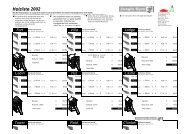
Step 15<br />
65<br />
H155<br />
8 1/4"<br />
20 1/8"<br />
65<br />
5/8"<br />
32"<br />
Upper Roof<br />
Assembly<br />
1. On the underside of the Lower Roof Panel, measure and drill pilot holes in locations shown using 1/8"<br />
drill bit. Holes must be in 5/8" from the edge of the Roof Frame side. Repeat this for the other side<br />
of the Panel using the same dimensions.<br />
2. Place the Roof Supports (65) on a hard surface aligning them to form a peak, position Roof Brace<br />
(18) on top of Roof Supports (65) and attach using #8 Hardware (H152).<br />
*NOTE: Make sure edges of Roof Supports (65) (18) are flush when installed properly.<br />
3. Position Roof Support Assembly on Lower Roof Assembly and attach using #8 Hardware (H155).<br />
Edges of Roof Supports (65) must be flush with the edges of the Lower Roof Frame when properly<br />
installed.<br />
34<br />
65<br />
18<br />
H152<br />
65<br />
EDGES FLUSH