Fiesta Playhouse Hardware List
Fiesta Playhouse Hardware List
Fiesta Playhouse Hardware List

Create successful ePaper yourself
Turn your PDF publications into a flip-book with our unique Google optimized e-Paper software.
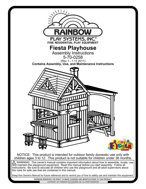
<strong>Fiesta</strong> <strong>Playhouse</strong><br />
Assembly Instructions<br />
5-70-0258<br />
(Rev 1 - 1.17.2011)<br />
Contains Assembly, Use, and Maintenance Instructions<br />
NOTICE: This product is intended for outdoor family domestic use only with<br />
children ages 3 to 12. This product is not suitable for children under 36 months.<br />
! WARNING: This owner's manual contains important information about how to assemble, locate, use,<br />
and maintain this playground equipment. Read this manual before you start assembly. Follow all<br />
instructions. Be sure to educate all children who use this playground and all adult supervisors about<br />
the rules for safe use that are contained in this manual.<br />
Keep this Owner's Manual for future reference and to remind you of how to safely use and maintain this equipment.<br />
RAINBOW RESERVES THE RIGHT TO MAKE CHANGES AND MODIFICATIONS TO THIS PRODUCT.<br />
COPYRIGHT 2011 RAINBOW PLAY SYSTEMS, INC. ALL RIGHTS RESERVED
OWNER'S MANUAL<br />
Rainbow Play Systems, Inc.<br />
Thank you for choosing Rainbow Play Systems, Inc. For you and your<br />
children's safety, please read the instruction manual thoroughly before<br />
you start building your Rainbow Play Systems, Inc. playground.<br />
Familiarize yourself with all hardware and parts to help with building your<br />
playground.<br />
WARNING: Failure to follow the assembly, location, use, and<br />
maintenance instructions in this manual could result<br />
in serious injury to children using this playground.<br />
Rules for Safe Play..........................................................................2<br />
Choosing Location of Play System..................................................3<br />
Choosing Proper Surface Material...................................................3-4<br />
Maintenance....................................................................................4<br />
Helpful Tips.....................................................................................5<br />
Commonly Asked Questions...........................................................6<br />
Parts Identification...........................................................................7-12<br />
<strong>Hardware</strong>.........................................................................................13-14<br />
Tools Required for Assembly..........................................................14<br />
Instructions......................................................................................15-35<br />
Warranty..........................................................................................36<br />
1
Safety Instructions<br />
Rules for Safe Play<br />
WARNING: Before allowing children to play on this equipment for the first time,<br />
carefully review the rules for safe play with them. Observing the following<br />
statements and warnings reduces the likelihood of a serious or fatal injury.<br />
1. IT IS RECOMMENDED that no more than 8 children, not exceeding a combined weight of 1,000 pounds, play<br />
on the system at one time. This product is recommended for children 3 to 12 years of age.<br />
2. CLOSE ADULT SUPERVISION is required, especially for younger children.<br />
3. WARN CHILDREN TO AVOID playing or walking in front of, behind, or between moving equipment.<br />
4. WARN CHILDREN NOT TO twist swing chains or ropes, or to loop them over the top support bar since this<br />
may reduce the strength of the chain or rope.<br />
5. INSTRUCT CHILDREN NOT TO swing empty swinging seats.<br />
6. INSTRUCT CHILDREN to always sit, never stand or kneel, in the center of the swing seat with their full weight.<br />
7. INSTRUCT CHILDREN NOT TO use any part of the play system in a manner other than what it is intended.<br />
8. INSTRUCT CHILDREN NOT TO get off equipment while it is in motion.<br />
9. DRESS CHILDREN APPROPRIATELY. CHILDREN SHOULD NOT wear scarves, hats with straps, helmets,<br />
jackets with draw strings, hooded jackets, poorly fitting shoes, or any other loose fitting clothing which could<br />
become entangled or snagged on equipment.<br />
10. INSTRUCT CHILDREN NOT TO play on the equipment if it is wet. Potentially slippery surfaces may cause a<br />
hazard.<br />
11. VERIFY all suspended items such as ropes and chains are secure at both ends.<br />
12. VERIFY all suspended items such as climbing ropes are tight so they cannot be looped back on themselves.<br />
13. INSTRUCT CHILDREN NOT TO attach items to the play system not specifically intended for use with the<br />
play equipment. Items such as, but not limited to, jump ropes, clotheslines, and pet leashes may pose a<br />
strangulation hazard.<br />
14. INSTRUCT CHILDREN TO REMOVE any bike or other sports helmets before playing on the play equipment, as<br />
they may pose a possible hanging hazard.<br />
15. INSTRUCT CHILDREN there may only be one person on a swing at a time with a maximum weight of 150<br />
pounds per swing.<br />
16. VERIFY there are no gaps between the slide bed way and the slide screws.<br />
17. INSTRUCT CHILDREN to always go down slides feet first. Never slide head first.<br />
18. INSTRUCT CHILDREN TO NEVER climb, crawl, or walk on items not intended for such use. Such types of play<br />
on top of Monkey Bars, Fort Roof, and Swing Beams greatly increase the risk of a serious or fatal fall.<br />
2
Choosing a location & protective surface for your play system<br />
When selecting your play site, always keep the child's safety in mind. Guidelines have been established by USCPSC that will help you<br />
achieve a safe play area:<br />
X3.1 Select Protective Surfacing - One of the most important things you can do to reduce the likelihood of serious head injuries is to install<br />
shock-absorbing protective surfacing under and around your play equipment. The protective surfacing should be applied to a depth that is<br />
suitable for the equipment height in accordance with ASTM Specification F 1292. There are different types of surfacing to choose from;<br />
whichever product you select, follow these guidelines:<br />
X3.1.1 Loose-Fill Materials:<br />
X3.1.1.1 Maintain a minimum depth of 9 inches of loose-fill materials such as wood mulch/chips, engineered wood fiber (EWF), or<br />
shredded/recycled rubber mulch for equipment up to 8 feet high; and 9 inches of sand or pea gravel for equipment up to 5 feet high. NOTE:<br />
An initial fill level of 12 inches will compress to about a 9-inch depth of surfacing over time. The surfacing will also compact, displace, and<br />
settle, and should be periodically refilled to maintain at least a 9-inch depth.<br />
X3.1.2 Use a minimum of 6 inches of protective surfacing for play equipment less than 4 feet in height. If maintained properly, this should be<br />
adequate. (At depths less than 6 inches, the protective material is too easily displaced or compacted.) NOTE: Do not install home<br />
playground equipment over concrete, asphalt, or any other hard surface. A fall onto a hard surface can result in serious injury to the<br />
equipment user. Grass and dirt are not considered protective surfacing because wear and environmental factors can reduce their shock<br />
absorbing effectiveness. Carpeting and thin mats are generally not adequate protective surfacing. Ground level equipment - such as a<br />
sandbox, activity wall, playhouse or other equipment that has no elevated play surface - does not need any protective surfacing.<br />
X3.1.3 Use containment, such as digging out around the perimeter and/or lining the perimeter with landscape edging. Don't forget to<br />
account for water drainage.<br />
X3.1.3.1 Check and maintain the depth of the loose-fill surfacing material. To maintain the right amount of loose-fill materials, mark the<br />
correct level on play equipment support posts. That way you can easily see when to replenish and/or redistribute the surfacing.<br />
X3.1.3.2 Do not install loose fill surfacing over hard surfaces such as concrete or asphalt.<br />
X3.1.4 Poured-In-Place Surfaces or Pre-Manufactured Rubber Tiles - You may be interested in using surfacing other than loose-fill materials<br />
- like rubber tiles or poured-in-place surfaces.<br />
X3.1.4.1 Installations of these surfaces generally require a professional and are not “do-it-yourself” projects.<br />
X3.1.4.2 Review surface specifications before purchasing this type of surfacing. Ask the installer/manufacturer for a report<br />
showing that the product has been tested to the following safety standard: ASTM F1292 Standard Specification for Impact<br />
Attenuation of Surfacing Materials within the Use Zone of Playground Equipment. This report should show the specific height<br />
for which the surface is intended to protect against serious head injury. This height should be equal to or greater than the fall<br />
height – vertical distance between a designated play surface (elevated surface for standing, sitting, or climbing) and the<br />
protective surfacing below – of your play equipment.<br />
X3.1.4.3 Check the protective surfacing frequently for wear.<br />
X3.1.5 Placement—Proper placement and maintenance of protective surfacing is essential. Be sure to:<br />
X3.1.5.1 Extend surfacing at least 6 feet from the equipment in all directions.<br />
X3.1.5.2 For to-fro swings, extend protective surfacing in front of and behind the swing to a distance equal to twice the<br />
height of the top bar from which the swing is suspended.<br />
X3.1.5.3 For tire swings, extend surfacing in a circle whose radius is equal to the height of the suspending chain or rope,<br />
plus 6 feet in all directions.<br />
Supplemental<br />
1. The play system should be located on solid level ground free of objects that could cause injury such as, but not limited to, tree stumps,<br />
roots, and large rocks. Stationary components such as ladders and slides must be no less than SIX FEET (1.8 meters) from any<br />
structure or obstruction such as a fence, garage, house, tree or overhanging branches, electrical wires or clotheslines. Any swinging<br />
equipment must be a minimum distance of TWICE the height of the swing<br />
beam away from any structures or obstructions as specified above. We<br />
also recommend that you do not install your play system near a lake, river,<br />
swimming pool or other water hazards.<br />
2. Locate slide out of direct sunlight to reduce the likelihood of serious burns.<br />
A slide that faces north will receive the least direct sunlight.<br />
3. It is recommended not to place a set on sandy soil or loose fill as it may<br />
require additional anchoring in that situation.<br />
4. If anchoring your play system, all underground utilities must be located in<br />
play zone before starting assembly of play system.<br />
Set Dimensions Play Zone<br />
L 8 1/2' x W 4 1/2' x H 7 1/2' L 20 1/2' x W 16 1/2'<br />
3<br />
16 1/2'<br />
6'<br />
min.<br />
6'<br />
min.<br />
6'<br />
min.<br />
20 1/2'<br />
6'<br />
min.
Maximum Fall Height is 2'<br />
TABLE 3.1 Fall Height in Feet From Which a Life Threatening Head Injury Would Not Be Expected<br />
Type of Material 6 in. depth 9 in. depth 12 in. depth<br />
Double Shredded Bark Mulch 6 ft. 10 ft. 11 ft.<br />
Wood Chips 6 ft. 7 ft. 12 ft.<br />
Fine Sand 5 ft. 5 ft. 9 ft.<br />
Fine Gravel 6 ft. 7 ft. 10 ft.<br />
Surfacing in "compressed" depths - See CPS & ASTM for Fall Heights of equipment<br />
Equipment Fall Height 1' 2' 3' 4' 5' 6' 7' 8' 9' 10' 11' 12'<br />
Wood Chips 6" 6" 6" 6" 6" 6" 6 1/2" 7 1/2" 8 1/4" 9" 12" 13"<br />
Double Shredded Bark Mulch 6" 6" 6" 6" 7" 8" 9" 9 3/4" 10 1/2" 11 1/2" 12" 13"<br />
Engineered Wood Fibers 6" 6" 6" 7" 8 1/2" 9" 9 1/2" 10 1/4" 10 3/4" 11" 10 3/4" 12"<br />
Fine Sand 6" 6" 6 1/2" 8" 9 10" 10 1/2" 11 1/4" 12" 13 1/2" 14 3/4" 16"<br />
Coarse Sand 6" 6" 7 1/2" 9" 10 1/2" 12" 14" 16" 18" 20" 22" 24"<br />
Fine Gravel 6" 6" 6" 6 3/4" 8" 9" 10" 10 3/4" 11 1/2" 12" 13 1/4" 14 1/2"<br />
Medium Gravel 6" 6 1/4" 8" 9" 9" 12" 14" 16" 18" 20" 22" 24"<br />
Chart obtained from U.S. Consumer Product Safety Commission Handbook for Public Playground Safety<br />
Assembly safety<br />
1. Wear safety glasses to protect your eyes from flying wood chips when drilling or cutting.<br />
2. Verify that all bolts and screws are secured tightly and all acorn nuts are snug (acorn nuts should be<br />
tightened to 5 foot pounds of torque).<br />
3. This product must be assembled by an adult. DO NOT allow children to play on the play system until it is<br />
completely assembled in a proper location.<br />
4. DO NOT allow children in the area while you are assembling your play system. Many of the Rainbow<br />
Play Systems, Inc. components are very heavy and could seriously injure a child.<br />
Maintenance of your play system<br />
To ensure safe enjoyment of your Rainbow Play System for years to come, follow these maintenance tips:<br />
1. At the beginning of each usage season and twice each month, check and tighten as needed (but do not over<br />
tighten causing wood to crack) all nuts and bolts. Acorn nuts should be tightened to 5 foot pounds of torque.<br />
<strong>Hardware</strong> used on swinging elements should be checked at least twice a month to ensure proper fastening.<br />
2. At the beginning of each usage season and twice each month, check all coverings for bolts and sharp edges<br />
to be certain they are in place. Replace when necessary.<br />
3. Oil all metallic moving parts and grease Tire Swivel monthly during the usage period.<br />
4. Check all moving parts including swing seats, ropes, and chains for wear, rust, or other deterioration and replace<br />
as needed.<br />
5. Check all metal parts for rust. If needed, sand and repaint using a nonlead-based paint meeting the<br />
requirements of Title 16 CFR Part 1303.<br />
6. Check the S-Hooks on the chains to ensure the gap is less than .040 inches. Tighten/close as necessary.<br />
7. Remove plastic swing seats and take indoors or do not use when temperature drops below 36 Fahrenheit.<br />
8. Check, twice a month, the depth of loose fill protective surfacing materials to prevent compaction and to<br />
maintain appropriate depth. Rake or replace as necessary.<br />
9. When you are ready to dispose of your playset, make sure all metal, plastic and wood components are<br />
disposed of in accordance with local waste ordinances and ensure that no unreasonable hazards exist.<br />
4
10. On a yearly basis, we recommend that you coat your play system with a sealant or preservative. You may<br />
also want to spot sand areas before sealing. Be sure that the sealant you select is non-toxic and child safe.<br />
11. Check all wood members for deterioration and splinters. Spot sand any areas that are checking or<br />
splintering. If parts are deteriorating, replace as needed.<br />
UPRIGHT<br />
WARNING<br />
Drilling, sawing, sanding or machining wood products generates wood dust,<br />
a substance known to the State of California to cause cancer. Avoid inhaling<br />
wood dust or use a dust mask or other safeguards for personal protection.<br />
California Health and Safety Code Section 25249.6<br />
PILOT<br />
HOLES DETAIL A<br />
Helpful Installation Hints<br />
*NOTE: Refer to these assembly tips throughout the entire installation process.<br />
1. After thoroughly reading all information and properly locating your play system site, carefully<br />
unpack parts. As you unpack your play system, keep the parts list handy and become familiar with each<br />
part before beginning assembly. Remember that a little extra time spent familiarizing yourself with the parts<br />
and instructions before you begin will help avoid mistakes and save you time later.<br />
2. Group both wood and non-wood parts together in accordance to each page, or Step, of this assembly<br />
manual. Doing this now will help you quickly locate parts and assemble the set with ease.<br />
3. Sort your hardware into groups of similar hardware pieces. Use a solid surface, such as the empty boxes,<br />
to ensure you do not lose any hardware.<br />
4. Before starting each Step, thoroughly read all of the instructions to ensure all information is understood.<br />
Pay special attention to the orientation of each part, details & notes, and proper usage of hardware. Each<br />
piece of hardware is required for a certain part of the assembly.<br />
5. Certain Steps of the assembly are best performed on a hard flat surface to ensure proper and accurate<br />
assembly.<br />
6. All Lag Bolts must have pre-drilled holes 2" deep (as shown in Detail A). Use a 1/8" drill bit for all<br />
1/4" and 5/16" Lag Bolts and use a 1/4" drill bit for all 3/8" Lag Bolts. Lag Bolts can be difficult to put<br />
in knot holes. Pre-drilling pilot holes will help to prevent the Lag Bolts from breaking. Refer to "Commonly<br />
Asked Questions" on page 6 for more information about Lag Bolts.<br />
7. All #14 Phillips Pan Head Tap Screws must have pre-drilled holes 1/2" deep. Use a 1/8" drill bit.<br />
8. Use a clamp to secure Facias flush to the Uprights and use holes in facia as a guide for placing Lag<br />
Bolt Pilot Holes (as shown in Detail B).<br />
9. Verify Facias are flush with Uprights.<br />
10. Check assembly periodically to ensure the set is level and all facias are square to the uprights.<br />
11. If a gap occurs between boards when inserting Screws or Lag Bolts, back out hardware and apply<br />
pressure to the top board while reinserting hardware in the same hole.<br />
FACIA<br />
FACES MUST<br />
BE FLUSH<br />
5<br />
DETAIL B<br />
USE FACIA AS<br />
A GUIDE FOR<br />
PRE-DRILLING<br />
HOLES
COMMONLY ASKED QUESTIONS<br />
Question: How do I know when Lag Bolts and other Fasteners are tightened properly?<br />
Answer: Lag Bolts and other Fasteners are tight when the head of the Lag Bolt and Washer<br />
are firmly compressed against the wood. If splintering occurs, that is an indication you<br />
are over tightening the Lag Bolts and other Fasteners. (Splintering is when the wood<br />
fibers fracture out from under the washers).<br />
Question: What should I do if a Lag Bolt or other Fastener lines up with a knot, or if the Lag Bolt<br />
breaks?<br />
Answer: There is extra <strong>Hardware</strong> provided with the set for this reason. Re-Drill a new hole with<br />
a 1/8" Drill Bit in a new direction to miss the obstruction.<br />
Question: What if my Play System is leaning and/or rocks?<br />
Answer: This is caused by unleveled ground under the Base and Support Wings of the Play<br />
System. It may be necessary to remove or add some soil beneath the Play System<br />
to make it level. Ground Stakes, when installed, will also provide stability.<br />
Question: What if my Play System has cracks on the wood or seems to be developing cracks?<br />
Answer: Seasonal checks, surface cracks, and knot holes are natural characteristics of all<br />
wooden play equipment. A check is a separation of the wood fibers running with the<br />
grain. This is caused by varying temperature and moisture conditions. By coating<br />
your Play System annually with a sealant or preservative, you can help protect your<br />
Play System from developing (not stopping) seasonal checks. Please remember to<br />
follow all installation instructions, including installing the play set on solid level ground.<br />
Question: What is the sticky substance that appears on the wood?<br />
Answer: The sticky substance that may appear on the wood is called pitch. It is common for<br />
the lumber to have occasional pitch seepage which does not affect the structural<br />
integrity of the part. Pitch provides the natural rot resistant characteristics of the<br />
lumber. If play surfaces or play items become overly sticky with pitch use rubbing<br />
alcohol to safely remove.<br />
Question: What accessories may be added or what modifications can be made to my Rainbow<br />
boxed kit set?<br />
Answer: Rainbow boxed kit sets are complete kits and are not modular. Play sets with<br />
unauthorized accessories or modifications will not be covered under warranty.<br />
Non-residential use of the play set voids warranty.<br />
Question: Is my child old enough to use all play items on my set?<br />
Answer: All play items on Rainbow boxed kit sets are designed<br />
for children ages 3 to 12, but it is the end users<br />
responsibility to determine suitability of use by their<br />
children for each play item.<br />
6<br />
EXAMPLE OF SEASONAL<br />
CHECKS OR SURFACE<br />
CRACKS
530<br />
309<br />
311<br />
362<br />
363<br />
403<br />
519<br />
520<br />
521<br />
522<br />
523<br />
524<br />
525<br />
526<br />
527<br />
528<br />
529<br />
FIESTA PLAYHOUSE PARTS LIST<br />
3@ 1 x 4 x 13" Window Horizontal (3-01-0135)<br />
4@ 1 x 4 x 10 7/8" Fan Ray (3-01-0072)<br />
2@ 1 x 4 x 16 1/2" Fan Vertical (3-01-0074)<br />
2@ 1 x 4 x 8 3/4" Fan Ray (3-01-0098)<br />
1@ 1 x 4 x 13" Fan Vertical (3-01-0099)<br />
6@ 1 x 4 x 36" Table Board (3-01-0120)<br />
12@ 1 x 4 x 54" Full Rail Upright (3-01-0124)<br />
70@ 1 x 4 x 17" Rail Upright (3-01-0125)<br />
2@ 1 x 4 x 17" Notched Rail Upright (3-01-0126)<br />
12@ 1 x 4 x 45" Floor Board (3-01-0127)<br />
2@ 1 x 4 x 39" Short Floor Board (3-01-0128)<br />
33@ 1 x 4 x 47" Roof Board (3-01-0129)<br />
8@ 1 x 4 x 7" Short Door Upright (3-01-0130)<br />
2@ 1 x 4 x 35 1/2" Fan Horizontal (3-01-0131)<br />
2@ 1 x 4 x 14 3/4" Window Side Trim (3-01-0132)<br />
3@ 1 x 4 x 13 1/2" Arched Window Top (3-01-0133)<br />
3@ 1 x 4 x 13 1/2" Window BTTM (3-01-0134)<br />
7<br />
531<br />
532<br />
533<br />
534<br />
535<br />
536<br />
537<br />
538<br />
539<br />
540<br />
541<br />
542<br />
543<br />
2@ 1 x 4 x 20" Short Door<br />
Upright (3-01-0137)<br />
1@ 1 x 4 x 19 1/4" Short Counter<br />
Top Brd (3-01-0138)<br />
4@ 1 x 4 x 6 1/2" Chimney<br />
Trim (3-01-0139)<br />
1@ 1 x 4 x 15 5/8" Right Dormer<br />
Board (3-01-0140)<br />
1@ 1 x 4 x 13 9/16" Right Dormer<br />
Board (3-01-0141)<br />
1@ 1 x 4 x 11 9/16" Right Dormer<br />
Brd (3-01-0142)<br />
1@ 1 x 4 x 9 1/2" Right Dormer<br />
Brd (3-01-0143)<br />
1@ 1 x 4 x 7 1/2" Right Dormer<br />
Brd (3-01-0144)<br />
1@ 1 x 4 x 5 7/16" Right Dormer<br />
Brd (3-01-0145)<br />
1@ 1 x 4 x 3 3/8" Right Dormer<br />
Brd (3-01-0146)<br />
1@ 1 x 4 x 15 5/8" Left Dormer<br />
Brd (3-01-0147)<br />
1@ 1 x 4 x 13 9/16" Left Dormer<br />
Brd (3-01-0148)<br />
1@ 1 x 4 x 11 9/16" Left Dormer<br />
Brd (3-01-0149)
544<br />
545<br />
546<br />
547<br />
548<br />
549<br />
378<br />
379<br />
550<br />
551<br />
53<br />
54<br />
55<br />
56<br />
57<br />
58<br />
355<br />
FIESTA PLAYHOUSE PARTS LIST<br />
1@ 1 x 4 x 9 1/2" Left Dormer Brd (3-01-0150)<br />
1@ 1 x 4 x 7 1/2" Left Dormer Brd (3-01-0151)<br />
1@ 1 x 4 x 5 7/16" Left Dormer Brd (3-01-0152)<br />
1@ 1 x 4 x 3 3/8" Left Dormer Brd (3-01-0153)<br />
8@ 1 x 4 x 6" Upper Leg Brace (3-01-0154)<br />
8@ 1 x 4 x 6" Lower Leg Brace (3-01-0155)<br />
1@ 1 x 6 x 18" Chimney Front (3-02-0025)<br />
1@ 1 x 6 x 12 1/8" Chimney Back (3-02-0026)<br />
1@ 1 x 6 x 20" Short Door Upright (3-02-0030)<br />
1@ 1 x 6 x 7" Short Door Upright (3-02-0031)<br />
1@ 2 x 4 x 19" Table Runner (3-03-0008)<br />
2@ 2 x 4 x 30" Left Picnic Table Leg (3-03-0009)<br />
2@ 2 x 4 x 30" Right Picnic Table Leg (3-03-0010)<br />
2@ 2 x 4 x 18 3/4" Table Brace (3-03-0011)<br />
2@ 2 x 4 x 45" Seat Support (3-03-0012)<br />
2@ 2 x 4 x 19" Table Support (3-03-0013)<br />
1@ 2 x 4 x 26" Fan Horizontal (3-03-0050)<br />
8<br />
357<br />
358<br />
359<br />
552<br />
555<br />
224<br />
380<br />
411<br />
1@ 2 x 4 x 24 1/4" Left Dormer<br />
Support (3-03-0052)<br />
1@ 2 x 4 x 24 1/4" Right Dormer<br />
Support (3-03-0053)<br />
1@ 2 x 4 x 6 5/8" Chimney Block<br />
(3-03-0054)<br />
1@ 2 x 4 x 6" Fan Center (3-03-0064)<br />
4@ 4 x 4 x 60" Corner Upright (3-06-0035)<br />
553 554<br />
2@ 4 x 4 x 51" Short Corner Upright (3-06-0036)<br />
8@ 5/4 x 4 x 12" Stool Leg<br />
(3-06-0037)<br />
11@ 5/4 x 4 x 45" 2 Hole Facia<br />
(3-09-0001)<br />
2@ 5/4 x 4 x 23 1/2" Dormer Runner<br />
(3-09-0033)<br />
2@ 5/4 x 4 x 36" Seat Board<br />
(3-09-0039)
556<br />
557<br />
558<br />
559<br />
560<br />
561<br />
562<br />
563<br />
564<br />
565<br />
566<br />
567<br />
568<br />
569<br />
570<br />
571<br />
FIESTA PLAYHOUSE PARTS LIST<br />
1@ 5/4 x 4 x 37" Counter Facia (3-09-0051)<br />
1@ 5/4 x 4 x 45" Arched Facia (3-09-0052)<br />
1@ 5/4 x 4 x 41" Outer Counter Top Brd (3-09-0053)<br />
2@ 5/4 x 4 x 12 3/4" Corner Facia (3-09-0054)<br />
2@ 5/4 x 4 x 41 1/4" Angled Trim Brd (3-09-0055)<br />
1@ 5/4 x 4 x 41" Counter Top Brd (3-09-0056)<br />
1@ 5/4 x 4 x 39" Short Counter Top Brd (3-09-0057)<br />
2@ 5/4 x 4 x 12" Flower Box Front (3-09-0058)<br />
2@ 5/4 x 4 x 10 1/8" Flower Box Bottom (3-09-0059)<br />
4@ 5/4 x 4 x 3 1/4" Flower Box Side (3-09-0060)<br />
2@ 5/4 x 4 x 32 1/8" Roof Frame Side (3-09-0061)<br />
6@ 5/4 x 4 x 51" Top/Bttm Roof Frame (3-09-0062)<br />
2@ 5/4 x 4 x 20 5/8" Roof Frame Side (3-09-0063)<br />
2@ 5/4 x 4 x 43 5/8" Roof Frame Side (3-09-0064)<br />
6@ 5/4 x 4 x 12 3/4" Window Vertical Trim (3-09-0066)<br />
3@ 5/4 x 4 x 12 3/4" Window Vertical (3-09-0067)<br />
9<br />
572<br />
573<br />
574<br />
575<br />
576<br />
577<br />
578<br />
579<br />
580<br />
581<br />
582<br />
583<br />
584<br />
1@ 5/4 x 4 x 18 1/4" Top Arched<br />
Door Trim (3-09-0068)<br />
2@ 5/4 x 4 x 18 1/4" Door Facia<br />
(3-09-0069)<br />
1@ 5/4 x 4 x 48" Runner Board<br />
(3-09-0070)<br />
1@ 5/4 x 4 x 25" Runner Board<br />
(3-09-0071)<br />
1@ 5/4 x 4 x 31 1/2" Runner Board<br />
(3-09-0072)<br />
3@ 5/4 x 4 x 5 1/2" Floor Runner<br />
Support (3-09-0074)<br />
1@ 5/4 x 4 x 45" Floor Runner<br />
(3-09-0075)<br />
2@ 5/4 x 4 x 37 7/16" Left Roof<br />
Support (3-09-0076)<br />
2@ 5/4 x 4 x 37 7/16" Right Roof<br />
Support (3-09-0077)<br />
1@ 5/4 x 4 x 48 1/2" Right Lean-To<br />
Roof Support (3-09-0078)<br />
1@ 5/4 x 4 x 48 1/2" Left Lean-To<br />
Roof Support (3-09-0079)<br />
1@ 5/4 x 4 x 44" Door Upright<br />
(3-09-0080)<br />
1@ 5/4 x 4 x 44" Door Upright<br />
w/Handle Hole (3-09-0081)
231<br />
382<br />
391<br />
586<br />
587<br />
588<br />
589<br />
590<br />
591<br />
592<br />
593<br />
594<br />
595<br />
585<br />
FIESTA PLAYHOUSE PARTS LIST<br />
5@ 5/4 x 6 x 45" 4 HOLE FACIA (3-10-0001)<br />
2@ 5/4 x 6 x 17 3/8" CHIMNEY SIDE (3-10-0016)<br />
2@ 5/4 x 6 x 36" SEAT BOARD (3-10-0019)<br />
1@ 5/4 x 6 x 87" 6 HOLE FACIA (3-10-0026)<br />
1@ 5/4 x 6 x 9 1/2" LEFT COUNTER SUPPORT (3-10-0027)<br />
1@ 5/4 x 6 x 9 1/2" RIGHT COUNTER SUPPORT (3-10-0028)<br />
2@ 5/4 x 6 x 45" ARCHED FACIA (3-10-0033)<br />
1@ 5/4 x 6 x 45" ARCHED FACIA (3-10-0034)<br />
2@ 5/4 x 6 x 12 3/4" 2 HOLE FACIA (3-10-0035)<br />
2@ 5/4 x 6 x 39" WINDOW TOP/BTTM (3-10-0036)<br />
1@ 5/4 x 6 x 18 1/4" ARCHED DOOR TRIM (3-10-0037)<br />
2@ 5/4 x 6 x 9" FAN CENTER (3-10-0038)<br />
4@ 5/4 x 6 x 10 1/4" STOOL SEAT (3-10-0039)<br />
2@ 5/4 x 4 x 6" DOOR HANDLE (3-09-0083)<br />
10<br />
N83<br />
1@ 5/8" RAINBOW PLAQUE<br />
(5-42-0028)<br />
N261<br />
1@ FLOOR DOORSTOP<br />
W/HARDWARE<br />
(5-47-0052)<br />
N262<br />
2@ 4" HINGE W/HARDWARE<br />
(5-47-0053)<br />
N263<br />
2@ DOOR KNOB<br />
(5-47-0054)
PARTS IDENTIFICATION<br />
533<br />
379<br />
537<br />
535<br />
378<br />
539<br />
534<br />
536<br />
567<br />
538<br />
566<br />
382<br />
540<br />
579<br />
358<br />
363<br />
309<br />
311<br />
362<br />
580<br />
552<br />
526<br />
594<br />
560<br />
357<br />
355<br />
567<br />
582<br />
520<br />
589<br />
589<br />
11<br />
403<br />
553<br />
562<br />
558 561<br />
587<br />
556<br />
554<br />
521<br />
520<br />
595<br />
548<br />
54<br />
559<br />
549<br />
519 519<br />
531<br />
531<br />
224<br />
231 559 231 550 573<br />
583<br />
555<br />
584
533<br />
PARTS IDENTIFICATION<br />
378<br />
579<br />
382<br />
309<br />
568<br />
311<br />
567<br />
567<br />
594<br />
526<br />
560<br />
524<br />
569<br />
567<br />
580<br />
520<br />
224<br />
592<br />
528<br />
589<br />
12<br />
530<br />
570<br />
403<br />
529<br />
554<br />
58<br />
595<br />
224<br />
548<br />
549<br />
563<br />
555<br />
520<br />
224<br />
224<br />
586<br />
56<br />
57<br />
565<br />
231
H32<br />
H22<br />
HARDWARE FOR ASSEMBLY<br />
H30<br />
H194<br />
H152<br />
H158<br />
H154<br />
H155<br />
13<br />
H9 H1<br />
H129<br />
H108<br />
H146<br />
H193<br />
H3<br />
H11<br />
0<br />
1<br />
2<br />
3<br />
4<br />
5<br />
6<br />
7<br />
8<br />
9
<strong>Fiesta</strong> <strong>Playhouse</strong> <strong>Hardware</strong> <strong>List</strong><br />
F/N# DESCRIPTION DIMENSION BAG/QTY<br />
H1 Flat Washer 1/4" 5-46-0666 @84<br />
H3 Flat Washer 3/8" 5-46-0666 @6<br />
H9 Lock Washer 1/4" 5-46-0666 @10<br />
H11 Lock Washer 3/8" 5-46-0666 @6<br />
H30 Round Pallet Nut 3/8" 5-46-0666 @6<br />
H32 4 Prong T-Nut 1/4" 5-46-0666 @8<br />
H22 Nyloc Nut 1/4" 5-46-0666 @2<br />
H108 Lag Bolt 5/16" x 3" 5-46-0666 @72<br />
H146 Hex Bolt 1/4" x 2 1/4" 5-46-0666 @8<br />
H193 Hex Bolt 1/4" x 2 3/4" 5-46-0666 @2<br />
H129 Hex Bolt 3/8" x 3 1/2" 5-46-0666 @6<br />
H194 Phillips Wood Screw #8 x 1 1/4" 5-46-0666 @728<br />
H152 Phillips Wood Screw #8 x 1 1/2" 5-46-0666 @178<br />
H154 Phillips Wood Screw #8 x 2" 5-46-0666 @48<br />
H155 Phillips Wood Screw #8 x 2 1/2" 5-46-0666 @4<br />
H158 Phillips Pan Head Tap Screw #10 x 1 1/2" 5-46-0666 @6<br />
EXAMPLE: 5-46-0666* @ 2**<br />
*DENOTES HARDWARE BAG<br />
**DENOTES QUANTITY NEEDED OUT OF HARDWARE BAG<br />
NOTE: EXTRA HARDWARE IS INCLUDED IN THE BAGS.<br />
NOT ALL HARDWARE WILL BE USED TO COMPLETE THE INSTALLATION.<br />
TOOLS REQUIRED FOR ASSEMBLY<br />
Tape Measure<br />
Carpenters Level<br />
Carpenters Square<br />
Rubber Mallet<br />
Claw Hammer<br />
Wood Clamp<br />
Standard or Cordless Drill<br />
with #2 & #3 Phillips Bits<br />
Electric Impact Gun or 1/4"<br />
and 3/8" Ratchet<br />
1/8" Drill Bit<br />
1/4" Drill Bit<br />
5/16" Drill Bit<br />
9/16" Drill Bit<br />
Torque Wrench<br />
Crescent Wrench<br />
14<br />
7/16" Deep Well Socket<br />
9/16" Deep Well Socket<br />
9/16" Box Wrench<br />
Safety Glasses<br />
Adult Helper
Step 1<br />
H108 H1<br />
H108<br />
553<br />
H108<br />
H1<br />
H1<br />
224<br />
554<br />
231<br />
44"<br />
553<br />
553<br />
589<br />
224<br />
INSET A<br />
44"<br />
553<br />
24"<br />
Wall Assembly<br />
*NOTE: Pre-drill holes for all 5/16" Lag Bolts with a 1/8" drill bit.<br />
1. Position Corner Uprights (553) (554) on the ground and insert 3/8" <strong>Hardware</strong> (H30) into pre-drilled<br />
holes (as shown in INSET A).<br />
2. On a flat surface, position Corner Uprights (553) (554) (as shown) with 3/8" <strong>Hardware</strong> (H30)<br />
facing in.<br />
*NOTE: Holes on 4 Hole Facias (231) are offset. See Detail B for proper installation.<br />
3. Place 4 Hole Facias (231) flush with the bottoms of Corner Uprights (553) (554), square and<br />
attach 4 Hole Facias (231) using 1/4" <strong>Hardware</strong> (H1) and 5/16" <strong>Hardware</strong> (H108).<br />
4. Position 2 Hole Facias (224) 1/2" down on Corner Uprights (553) and 50" up on Corner Uprights<br />
(554) and attach using 1/4" <strong>Hardware</strong> (H1) and 5/16" <strong>Hardware</strong> (H108).<br />
*NOTE: Make sure each wall assembly is square at this time.<br />
5. Position two 2 Hole Facias (224) directly on top of 4 Hole Facias (231) (as shown) and attach<br />
to Corner Uprights (553) using 1/4" <strong>Hardware</strong> (H1) and 5/16" <strong>Hardware</strong> (H108).<br />
6. Position 2 Hole Facias (224) 22" up on Corner Uprights (554) and 24" up on Corner Uprights<br />
(553) (as shown) and attach using 1/4" <strong>Hardware</strong> (H1) and 5/16" <strong>Hardware</strong> (H108).<br />
7. Position Arched Facias (589) (590) 44" up on Corner Uprights (553) and attach using 1/4"<br />
<strong>Hardware</strong> (H1) and 5/16" <strong>Hardware</strong> (H108).<br />
8. Position Arched Facia (589) up against the bottom of 2 Hole Facia (224) and attach to Corner<br />
Uprights (554) using 1/4" <strong>Hardware</strong> (H1) and 5/16" <strong>Hardware</strong> (H108).<br />
224<br />
231<br />
45"<br />
15<br />
224<br />
590<br />
553<br />
224<br />
H30<br />
1/2"<br />
1 3/4"<br />
THIS HOLE UP<br />
224<br />
B<br />
589<br />
224<br />
554<br />
231<br />
H30<br />
DETAIL B<br />
DETAIL A<br />
H1<br />
22"<br />
50"<br />
H108
Step 2<br />
ASSEMBLY 1<br />
53 3/4"<br />
H108<br />
H1<br />
HOLE<br />
UP<br />
231<br />
557<br />
553<br />
H108<br />
DETAIL A<br />
589<br />
H1<br />
45"<br />
224<br />
HOLE<br />
DOWN<br />
224<br />
Wall Assembly<br />
*NOTE: Pre-drill holes for all 5/16" Lag Bolts with a 1/8" drill bit.<br />
*NOTE: Two to Three people should be used to complete this step.<br />
1. Position Wall Assembly 1 and Wall Assembly 2 (as shown).<br />
2. Join Wall Assemblies 1 and 2 by attaching 4 Hole Facia (231) and 6 Hole Facia (586) using 1/4"<br />
<strong>Hardware</strong> (H1) and 5/16" <strong>Hardware</strong> (H108). Uprights should measure 45" from outside to outside.<br />
*NOTE: Holes on 4 Hole Facias (231) are offset. See Detail A for proper installation.<br />
3. Measure up 53 3/4" and attach Arched Facia (557) to Corner Uprights (553) using 1/4" <strong>Hardware</strong><br />
(H1) and 5/16" <strong>Hardware</strong> (H108).<br />
4. Position 2 Hole Facia (224) flush with the top of previously installed 2 Hole Facia (224) and<br />
attach to Corner Uprights (553) using 1/4" <strong>Hardware</strong> (H1) and 5/16" <strong>Hardware</strong> (H108) (as shown<br />
in Detail B).<br />
5. Position 4 Hole Facia (231) flush with the tops of Arched Facias (589) (590) (as shown) and<br />
attach to Corner Uprights (553) using 1/4" <strong>Hardware</strong> (H1) and 5/16" <strong>Hardware</strong> (H108).<br />
6. Position Wall Assembly 3 (as shown) and attach to 6 Hole Facia (586) using 1/4" <strong>Hardware</strong> (H1)<br />
and 5/16" <strong>Hardware</strong> (H108).<br />
*NOTE: Wall Assembly 3 will not be fully stable at this point. Stabilize until Step 11.<br />
7. Position 2 Hole Facias (224) approximately 5/8" below 4 Hole Facias (231) (as shown in Inset C)<br />
and attach to Corner Uprights (553) using 1/4" <strong>Hardware</strong> (H1) and 5/16" <strong>Hardware</strong> (H108).<br />
A<br />
231<br />
590<br />
224<br />
B<br />
42"<br />
H1<br />
H1<br />
ASSEMBLY 2<br />
24"<br />
H108<br />
H108<br />
231<br />
231 4 5/8"<br />
DETAIL B<br />
16<br />
ASSEMBLY 3<br />
586<br />
5/8"<br />
224<br />
231<br />
H1<br />
554<br />
INSET C<br />
H108<br />
553<br />
586<br />
224
231<br />
Step 3<br />
553<br />
224<br />
577<br />
523<br />
H152<br />
522<br />
H194<br />
DETAIL A<br />
224<br />
231<br />
Floor Installation<br />
1. Opposite one another, center Runner Blocks (577) horizontally and 1 9/16" down from the top of 4<br />
Hole Facias (231) and attach to 4 Hole Facias (231) using #8 <strong>Hardware</strong> (H152).<br />
2. Center Runner Board (578) on top of Runner Blocks (577) and attach using #8 <strong>Hardware</strong> (H152).<br />
3. Evenly space Floor Boards (522) (523) across 2 Hole Facias (224) and attach using #8 <strong>Hardware</strong><br />
(H194).<br />
4. Attach Flower Box Sides (565) to Flower Box Bottom (564) using #8 <strong>Hardware</strong> (H152) (as shown<br />
in INSET A).<br />
5. Attach Flower Box Front (563) to Flower Box Sides (565) using #8 <strong>Hardware</strong> (H152).<br />
*SUGGESTION: Mark measurements for attaching assembled Flower Boxes and transfer<br />
measurements to the back side of 2 Hole Facia (224) to ensure wood<br />
screws protrude into Flower Box Sides (565) and Flower Box Bottom (564).<br />
6. Position assembled Flower Boxes against 2 Hole Facia (224) (as shown) and attach using #8<br />
<strong>Hardware</strong> (H154).<br />
578<br />
H152<br />
17<br />
231<br />
H152<br />
565<br />
564<br />
H154<br />
565<br />
INSET A<br />
563<br />
224<br />
565<br />
H152<br />
8"
Step 4<br />
554<br />
224<br />
231<br />
520<br />
3 1/2"<br />
554<br />
H194<br />
590<br />
224<br />
Rail Installation<br />
*NOTE: All Railing installations should fit snug with no or minimal space in between each<br />
Board (520) (519).<br />
*NOTE: Ensure pre-drilled screw holes hit the flat surface of the facias they attach to.<br />
1. Position Rail Uprights (520) (as shown) against 4 Hole Facia (231) and 2 Hole Facia (224) and<br />
attach using #8 <strong>Hardware</strong> (H194).<br />
*NOTE: Full Rail Uprights (519) and Rail Uprights (520) should rest directly on the Floor<br />
Boards.<br />
2. Position Full Rail Uprights (519) (as shown) and attach to Facias (224) (590) using #8 <strong>Hardware</strong><br />
(H194).<br />
3. Position Rail Uprights (520) (as shown) and attach to Facias (224) (590) using #8 <strong>Hardware</strong><br />
(H194). Top Rail Uprights (520) should be flush with the tops of Full Rail Uprights (519).<br />
519<br />
520<br />
18<br />
224<br />
224<br />
590<br />
519<br />
H194<br />
H194<br />
H194<br />
557
Step 5<br />
589<br />
224<br />
587<br />
18 1/8"<br />
224<br />
553<br />
224 520 H194<br />
H1 H108<br />
520 H194<br />
231<br />
2 HOLE FACIA REMOVED<br />
FROM VIEW FOR CLARITY<br />
588<br />
Rail Installation<br />
*NOTE: All Railing installations should fit snug with no or minimal space in between each<br />
Boards (519) (520).<br />
*NOTE: Ensure pre-drilled screw holes hit the flat surface of the facias they attach to.<br />
1. Measure up 18 1/8" on Corner Uprights (553) and attach Left Counter Support (587) and Right<br />
Counter Support (588) using 1/4" <strong>Hardware</strong> (H1) and 5/16" <strong>Hardware</strong> (H108).<br />
2. Position Corner Facias (559) and 2 Hole Facias (591) (in locations shown) and attach to Corner<br />
Uprights (553) using 1/4" <strong>Hardware</strong> (H1) and 5/16" <strong>Hardware</strong> (H108).<br />
3. Attach Rail Uprights (520) (in locations shown) to 2 Hole Facias (224) and Arched Facia (589)<br />
using #8 <strong>Hardware</strong> (H194).<br />
4. Position Full Rail Uprights (519) (in locations shown) and attach to Corner Facias (559) and 2 Hole<br />
Facias (591) using #8 <strong>Hardware</strong> (H194). When properly installed, the door opening should<br />
measure approximately 19 1/2" (as shown).<br />
519<br />
559<br />
19<br />
H194<br />
591<br />
19 1/2"<br />
H1<br />
519<br />
553<br />
590<br />
H1<br />
559<br />
H108<br />
H108
Step 6<br />
561<br />
558<br />
562<br />
553<br />
587<br />
521<br />
H152<br />
556<br />
577<br />
224<br />
INSET A 520<br />
H152<br />
H194<br />
558<br />
520<br />
587<br />
521<br />
561<br />
Rail & Counter<br />
Installation<br />
*NOTE: All Railing installation should fit snug with no or minimal space in between each<br />
part.<br />
1. Center Short Counter Top Board (532) on 2 Hole Facia (224) and attach to 2 Hole Facia (224)<br />
using #8 <strong>Hardware</strong> (H152).<br />
2. Flush back of Short Counter Top Board (562) with the inside of Corner Uprights (553) and attach<br />
to Counter Supports (587) (588) using #8 <strong>Hardware</strong> (H152).<br />
3. Position Counter Top Boards (561) (558) and attach to Counter Supports (587) (588) using #8<br />
<strong>Hardware</strong> (H152).<br />
4. Position Notched Rail Uprights (521) (in locations shown) and attach to 2 Hole Facia (224) using<br />
#8 <strong>Hardware</strong> (H194).<br />
5. Position Counter Facia (556) between Counter Supports (587) (588), against the bottom of<br />
the counter boards, and attach to Counter Supports (587) (588) using #8 <strong>Hardware</strong> (H152).<br />
6. Attach Notched Rail Uprights (521) to Counter Facia (556) using #8 <strong>Hardware</strong> (H194).<br />
7. Attach Rail Uprights (520) to 2 Hole Facia (224) and Counter Facia (556) using #8 <strong>Hardware</strong><br />
(H194).<br />
8. Center Runner Support (577) on counter boards and attach using #8 <strong>Hardware</strong> (H152).<br />
562<br />
H152<br />
532<br />
224<br />
588 H152<br />
521<br />
20
Step 7<br />
H152<br />
580<br />
567<br />
EDGE CLOSEST<br />
TO HOLE MUST<br />
FACE IN<br />
567<br />
566<br />
H194<br />
H194<br />
580<br />
45"<br />
579<br />
566<br />
H152<br />
Roof Panel<br />
Assembly<br />
*SUGGESTION: Using a second person to stabilize or help hold supports while assembling<br />
this step will ensure assembly remains square.<br />
*SUGGESTION: Complete this step on a flat surface.<br />
1. Position Left Roof Support (579) and Right Roof Support (580) 45" apart (from inside face to inside<br />
face) on a flat surface.<br />
2. Position Top/Bottom Roof Frames (567), with holes facing in, centered on top of Supports (579)<br />
(580).<br />
3. Top Roof Frame (567) should extend past the tip of Supports (579) (580) no more than a 1/4".<br />
Position the Bottom Roof Frame (567) 32 1/8" from the Top Roof Frame (567). Attach Frames<br />
(567) to Supports (579) (580) using #8 <strong>Hardware</strong> (H152).<br />
*NOTE: Make sure assembly is square before completing part 4 of this step.<br />
*SUGGESTION: Use Roof Frame Sides (566) to properly position (center) Roof Boards (524).<br />
4. Position Roof Boards (524), centered and evenly spaced, on Supports (579) (580) and attach<br />
using #8 <strong>Hardware</strong> (H194).<br />
5. Place Roof Frame Sides (566) on the ends of Roof Boards (524) and attach using #8 <strong>Hardware</strong><br />
(H152).<br />
6. Position Runner Board (576) (as shown) on the underside of Roof Boards (524) and attach using<br />
#8 <strong>Hardware</strong> (H194) and to Top Roof Frame (567) using #8 <strong>Hardware</strong> (H152).<br />
H152<br />
1/4"<br />
3"<br />
524<br />
COUNTER SUNK<br />
HOLES FACE OUT<br />
21<br />
567<br />
579<br />
567<br />
567<br />
576<br />
32 1/8"<br />
INSET A<br />
1"<br />
567<br />
INSET B<br />
567<br />
576<br />
H152<br />
576<br />
H152<br />
567
Step 8<br />
H152<br />
567<br />
45"<br />
580<br />
EDGE CLOSEST<br />
TO HOLE MUST<br />
FACE IN<br />
567<br />
H194<br />
H194<br />
568<br />
H152<br />
579<br />
568 H152<br />
524<br />
Short Roof<br />
Panel Assembly<br />
*SUGGESTION: Using a second person to stabilize or help hold supports while assembling<br />
this step will ensure assembly remains square.<br />
*SUGGESTION: Complete this step on a flat surface.<br />
1. Position Left Roof Support (579) and Right Roof Support (580) 45" apart (from inside face to<br />
inside face) on a flat surface.<br />
2. Position Top/Bottom Roof Frames (567), with holes facing in, centered on top of Supports (579)<br />
(580).<br />
3. Top Roof Frame (567) should extend past the tip of Supports (579) (580) no more than a 1/4".<br />
Position the Bottom Roof Frame (567) 20 5/8" from the Top Roof Frame (567). Attach Frames<br />
(567) to Supports (579) (580) using #8 <strong>Hardware</strong> (H152).<br />
*NOTE: Make sure assembly is square before completing part 4 of this step.<br />
*SUGGESTION: Use Roof Frame Sides (568) to properly position (center) Roof Boards (524).<br />
4. Position Roof Boards (524), centered and evenly spaced, on Supports (579) (580) and attach<br />
using #8 <strong>Hardware</strong> (H194).<br />
5. Place Roof Frame Sides (568) on the ends of Roof Boards (524) and attach using #8 <strong>Hardware</strong><br />
(H152).<br />
6. Position Runner Board (575) (as shown) on the underside of Roof Boards (524) and attach using<br />
#8 <strong>Hardware</strong> (H194) and to Top Roof Frame (567) using #8 <strong>Hardware</strong> (H152).<br />
567<br />
567<br />
1/4"<br />
567 567<br />
3" 20 5/8"<br />
INSET A<br />
579<br />
580<br />
COUNTER SUNK<br />
HOLES FACE OUT<br />
22<br />
580<br />
H152<br />
575<br />
579<br />
575<br />
INSET B<br />
524<br />
H152<br />
567<br />
1"<br />
H152<br />
567<br />
575
Step 9<br />
H3<br />
H129 H11<br />
N83<br />
579<br />
553<br />
DETAIL A<br />
591<br />
H158<br />
553<br />
A<br />
Roof Panel<br />
Installation<br />
*SUGGESTION: Use two people to complete this step.<br />
*NOTE: Do not fully tighten thru bolt <strong>Hardware</strong> in this step.<br />
1. Lift full roof panel into position (as shown) and attach to Corner Uprights (553) using previously<br />
installed 3/8" <strong>Hardware</strong> (H30) and 3/8" <strong>Hardware</strong> (H3) (H11) (H129).<br />
2. Lift short roof panel into position (as shown) and attach to Corner Uprights (553) using previously<br />
installed 3/8" <strong>Hardware</strong> (H30) and 3/8" <strong>Hardware</strong> (H3) (H11) (H129).<br />
3. Center Plaque (N83) on 2 Hole Facia (591) and attach using #10 <strong>Hardware</strong> (H158) (as shown in<br />
Detail A).<br />
23<br />
580<br />
H30<br />
553<br />
H11<br />
579<br />
H129<br />
H3
Step 10<br />
560<br />
H155<br />
557<br />
519<br />
H194<br />
579 580<br />
525<br />
Upper Rail<br />
Installation<br />
*SUGGESTION: Use two people to complete this step.<br />
1. Position roof sides so no gap exists between mating faces of Left Roof Support (579) and Right<br />
Roof Support (580).<br />
2. Position Angled Trim Boards (560) (as shown) with angled faces against Roof Supports (579)<br />
(580), with faces flush (as shown) and attach using #8 <strong>Hardware</strong> (H155).<br />
3. Attach top of Full Rail Uprights (519) to Angled Trim Boards (560) (as shown) using #8 <strong>Hardware</strong><br />
(H194). Attach Rail Uprights (520) to Angled Trim Board (560) and 4 Hole Facia (231) using #8<br />
<strong>Hardware</strong> (H194).<br />
4. Attach Short Rail Uprights (525) to Angled Trim Boards (560) and Arched Facia (557)<br />
using #8 <strong>Hardware</strong> (H194).<br />
24<br />
H194<br />
580<br />
560<br />
520<br />
FLUSH<br />
NO GAP<br />
579<br />
231
Step 11<br />
594<br />
526<br />
560<br />
579<br />
309<br />
311<br />
580<br />
580<br />
Fan and Lean-to<br />
Roof Support Installation<br />
1. On a flat surface arange Fan Horizontal (526), Fan Vertical (311), Fan Rays (309), and Fan Center<br />
(594) and attach using #8 <strong>Hardware</strong> (H194).<br />
2. Position Fan Assemblies on top of Angled Trim Boards (560) and attach to Left and Right Roof<br />
Supports (579) (580) using #8 <strong>Hardware</strong> (H194).<br />
*Note: Tighten thru bolt hardware used to attach Left and Right Roof Supports (579) (580)<br />
at this time.<br />
3. Attach Left and Right Lean-to Roof Supports (581) (582) to Short Corner Uprights (554) using<br />
previously installed 3/8" <strong>Hardware</strong> (H30) and 3/8"<strong>Hardware</strong> (H3) (H11) (H129).<br />
4. Attach Left and Right Lean-to Roof Supports (581) (582) to Left and Right Roof Supports (579)<br />
(580) using #8 <strong>Hardware</strong> (H154).<br />
*NOTE: Check to ensure assembly is square and level.<br />
H194<br />
309<br />
579<br />
H194<br />
42"<br />
H154<br />
582<br />
16 1/8"<br />
526 594<br />
45°<br />
25<br />
311<br />
7/8"<br />
13 1/4"<br />
H30<br />
581<br />
554<br />
526<br />
H194<br />
H3<br />
309<br />
H129<br />
H11<br />
311<br />
309<br />
594
Step 12<br />
582<br />
Lean-to Roof<br />
Support Installation<br />
1. Position Top Roof Frame (567) (with holes facing in) across Lean-to Roof Supports (581) (582),<br />
up against previously installed Bottom Roof Frame (567), and attach to Supports (581) (582)<br />
using #8 <strong>Hardware</strong> (H152).<br />
2. Measure 43 5/8" in between Top/Bottom Roof Frames (567) and attach Bottom Roof Frame (567)<br />
(with holes facing in) to Lean-to Roof Supports (581) (582).<br />
3. Evenly space Roof Boards (524) across Lean-to Roof Supports (581) (582) and attach using #8<br />
<strong>Hardware</strong> (H194).<br />
4. Position Side Frames (569) on Roof Boards (524) and attach using #8 <strong>Hardware</strong> (H152).<br />
5. Center Roof Support (574) on Roof Boards (524) and Top/Bottom Roof Frames (567). Attach<br />
Roof Runner (574) to Roof Boards (524) using #8 <strong>Hardware</strong> (H194) and to Top/Bottom Roof<br />
Frames using #8 <strong>Hardware</strong> (H152).<br />
567<br />
26<br />
524<br />
569<br />
H194<br />
H194<br />
43 5/8"<br />
567<br />
574<br />
H152<br />
574<br />
567<br />
H152<br />
H152<br />
581<br />
567<br />
INSET A<br />
INSET B<br />
524
Step 13<br />
H194 527<br />
570<br />
530<br />
529<br />
H194<br />
Window Installation<br />
1. Position Window Top/Bottoms (592) flush with the inside of 4 Hole Facia (231) and 2 Hole Facia<br />
(224) and attach using #8 <strong>Hardware</strong> (H154).<br />
2. Position Window Side Trim pieces (527) on ends of Window Top/Bottoms (592) and attach using<br />
#8 <strong>Hardware</strong> (H194).<br />
3. Position Arched Window Tops (528) and Window Bottoms (529) flush with Window Top/Bottoms<br />
(592) and attach to Window Top/Bottoms (592) using #8 <strong>Hardware</strong> (H194).<br />
4. Position Window Vertical Trim (570) pieces flush with the ends of Arched Window Tops (528) and<br />
Window Bottoms (529) and attach to Arched Window Tops (528) and Window Bottoms (529) using<br />
#8 <strong>Hardware</strong> (H194).<br />
5. Center Window Vertical (571) in window openings and attach to Arched Window Tops (528) and<br />
Window Bottoms (529) using #8 <strong>Hardware</strong> (H194).<br />
6. Center Window Horizontal (530) in window openings and attach to Window Vertical Trim (570)<br />
using #8 <strong>Hardware</strong> (H194).<br />
231<br />
527<br />
592<br />
H194<br />
592<br />
224<br />
H154<br />
530<br />
570<br />
571<br />
H194 571 530 571 H194<br />
27<br />
592<br />
571<br />
529<br />
H194<br />
528<br />
530<br />
570<br />
H194
Step 14<br />
H158<br />
N263<br />
572<br />
H152<br />
COUNTER-SUNK<br />
HOLES<br />
551<br />
525<br />
584<br />
525<br />
572<br />
583<br />
585<br />
1 3/8"<br />
593<br />
H194<br />
585<br />
Door Assembly<br />
1. Attach Door Knobs (N263) to Door Handles (585) using #10 <strong>Hardware</strong> (H158) (as shown). Sink<br />
the head of #10 <strong>Hardware</strong> (H158) into the wood so the top of the screw head does not stick out of<br />
the Door Handles (585).<br />
2. Position Door Uprights (583) (584), bottom Door Facia (573), and Top Arched Door Trim (572) (as<br />
shown) on a flat surface and attach using #8 <strong>Hardware</strong> (H152). Top Arched Door Trim (572)<br />
should overlap Door Uprights (551) (525) (583) (584) by 1 3/8" (as shown).<br />
3. Position middle Door Facia (573), Arched Door Trim (593), and Door Uprights (531) (550) (525)<br />
(551) (in locations shown) and attach using #8 <strong>Hardware</strong> (H194).<br />
*NOTE: Do not over-tighten hardware in parts 4 and 5. Door Handles should swing freely.<br />
4. Postion Door Handles (585) so rear counter-sunk holes align with pre-drilled hole and attach using<br />
1/4" <strong>Hardware</strong> (H1) (H9) (H22) (H193).<br />
5. Finish attaching Door Handles (585) through the arc of Door Upright w/Handle Hole (584) using<br />
1/4" <strong>Hardware</strong> (H1) (H9) (H22) (H193).<br />
H1<br />
H193<br />
H9<br />
45 3/4"<br />
H152<br />
573<br />
38 5/8"<br />
28<br />
H22<br />
H1<br />
584<br />
20"<br />
H194<br />
531<br />
593 573 573<br />
H152<br />
531<br />
550<br />
573<br />
531<br />
550<br />
531<br />
18 1/4"<br />
583<br />
H194<br />
H152
Step 15<br />
591<br />
N261<br />
N261<br />
522<br />
H194<br />
559<br />
H157<br />
N262<br />
5/16" PILOT<br />
HOLE DETAIL A<br />
573<br />
Door Installation<br />
1. Center and attach Hinges (N262) to bottom Door Facia (573) and Arched Door Trim (593) using<br />
<strong>Hardware</strong> provide in Hinge bag (as shown in INSET A).<br />
2. Using a helper, center and attach door assembly to Corner Facia (559) and 2 Hole Facia (591)<br />
using <strong>Hardware</strong> provided in Hinge bag. The gaps should measure 5/8" on top and sides, and 1/8"<br />
on the bottom when properly installed.<br />
3. With door closed and handle down in locked position, position Door Stop (N261) against the<br />
inside of Door Upright w/Handle Holes (584) and mark placements for Standoff and screw<br />
(approximately 1 1/8" apart).<br />
4. Pre-drill 5/16" Diameter hole and insert Standoff.<br />
5. Position Door Stop (N261) on standoff and secure in place with screw provided in Door Stop Bag.<br />
231<br />
231<br />
559<br />
519<br />
559<br />
N262<br />
29<br />
H157<br />
5/8"<br />
559 559<br />
231<br />
5/8" 1/8" 5/8"<br />
N262<br />
573<br />
593<br />
584<br />
INSET A<br />
573
Step 16<br />
358<br />
541<br />
542<br />
543<br />
544<br />
545<br />
546<br />
547<br />
534<br />
362<br />
363<br />
357<br />
355<br />
INSET A<br />
H152<br />
H154<br />
355<br />
Dormer Assembly<br />
1. On a flat surface arrange Right Dormer Support (358), Left Dormer Support (357), and Fan<br />
Horizontal (355) (as shown in Inset A & B) and attach using #8 <strong>Hardware</strong> (H154).<br />
2. Position Fan Vertical (363), Fan Rays (362), and Fan Center (552) (as shown in Inset A & B)<br />
and attach using #8 <strong>Hardware</strong> (H152).<br />
3. Attach top two Roof Boards (534) (541) to Dormer Supports (357) (358) using #8 <strong>Hardware</strong><br />
(H194). No gap should exist at the peak between the top two Roof Boards.<br />
4. Continue attaching all Roof Boards to Dormer Supports (357) (358) using #8 <strong>Hardware</strong> (H194).<br />
5. Position Dormer Runners (380) (as shown in lower right diagram) and attach to Roof Boards using<br />
#8 <strong>Hardware</strong> (H194) and to Dormer Supports (357) (358) using #8 <strong>Hardware</strong> (H154).<br />
H152<br />
H194<br />
357<br />
355<br />
15/16"<br />
358<br />
540<br />
FLUSH EDGE WITH<br />
ANGLED FACE<br />
30<br />
539<br />
362<br />
538<br />
357<br />
3/4"<br />
H194<br />
537<br />
536<br />
552<br />
535<br />
INSET B<br />
534<br />
H154<br />
363<br />
358<br />
45°<br />
7 7/8"<br />
H194<br />
362<br />
541<br />
NO SPACE<br />
BETWEEN<br />
MATING FACES<br />
H194<br />
380<br />
H154
Step 17<br />
380<br />
INSET A<br />
H152<br />
Dormer Installation<br />
1. Position Dormer assembly on roof. Dormer assembly should be centered horizontally and Dormer<br />
Supports (357) (358) should be flush with bottom edge of the third Roof Board (524) (as shown in<br />
INSET B).<br />
2. Attach Dormer assembly to the roof through Roof Boards (524), into Dormer Runners (380) using<br />
#8 <strong>Hardware</strong> (H152).<br />
380<br />
ON EDGE<br />
31<br />
524<br />
357<br />
INSET B<br />
524<br />
358
Step 18<br />
H154<br />
H194<br />
379<br />
H194<br />
566<br />
INSET A<br />
378<br />
533<br />
9"<br />
359<br />
382<br />
Chimney Installation<br />
*NOTE: For proper installation, ensure angled faces on Chimney parts (378) (379) (382) are<br />
all flush with one another.<br />
1. On a flat surface, stand Chimney Sides (382), Chimney Back (379), and Chimney Front (378) on<br />
end (as shown) and attach using #8 <strong>Hardware</strong> (H194).<br />
2. Center Chimney Trim (533) pieces on Chimney Sides (382) and attach using #8 <strong>Hardware</strong> (H194).<br />
3. Center Chimney Trim (533) pieces on Chimney Back (379) and Chimney Front (378) and attach<br />
using #8 <strong>Hardware</strong> (H194).<br />
4. Place Chimney Block (359) flush with angled faces of Chimney Sides (382) and attach through<br />
Chimney Sides (382) using #8 <strong>Hardware</strong> (H154).<br />
5. Position Chimney assembly on roof in desired location and attach through the underside of Roof<br />
Boards (524) into Chimney Block (359) using #8 <strong>Hardware</strong> (H154).<br />
H154<br />
H194<br />
32<br />
H154<br />
359<br />
524<br />
524
Step 19<br />
55<br />
H146<br />
H1<br />
H146 H9 H1<br />
H9<br />
H1<br />
57<br />
58<br />
54<br />
Picnic Table<br />
Assembly<br />
1. Place Left Table Legs (54), Right Table Legs (55) and Seat Supports (57) on a hard surface and<br />
pound in T-Nuts (H32) with a hammer (as shown in Inset A).<br />
*NOTE: Counter-sunk holes on Table Legs (54) (55) must be facing down.<br />
2. Line up holes on Left Table Legs (54), Right Table Legs (55), Seat Supports (57) and Table Support<br />
(58) (as shown) and attach using 1/4" <strong>Hardware</strong> (H1) (H9) (H146) (H32).<br />
57<br />
57<br />
54<br />
33<br />
H1<br />
55<br />
H9<br />
55<br />
H146<br />
54<br />
58<br />
54<br />
55<br />
H1<br />
H9<br />
H146<br />
H32<br />
H32<br />
INSET A<br />
H32
Step 20<br />
H154<br />
391<br />
57<br />
411<br />
403<br />
53<br />
58<br />
H154<br />
H154<br />
H152<br />
56<br />
H154<br />
55 54<br />
Picnic Table<br />
Assembly<br />
1. Stand Leg assemblies up and center Seat Boards (391) (411) on Seat Supports (57). Seat Boards<br />
(391) (411) should overhang 3 3/8" on the ends and the edges of Seat Boards (391) and Seat<br />
Supports (57) must be flush (as shown). Attach Seat Boards (391) (411) to Seat Supports (57)<br />
using #8 <strong>Hardware</strong> (H154).<br />
2. Center Table Boards (403) on Table Supports (58) and attach using #8 <strong>Hardware</strong> (H152). There<br />
should be no gaps between Table Boards (403) when attached properly.<br />
*NOTE: Assembling Picnic Table on a hard level surface will help ensuring that the<br />
Table is square.<br />
3. Insert Screws (H154) into holes on Left Table Legs (54) and Right Table Legs (55) and attach to<br />
Table Supports (58) using #8 <strong>Hardware</strong> (H154).<br />
4. Center and attach Table Runner (53) on the bottom side of Table Boards (403) using #8 <strong>Hardware</strong><br />
(H152).<br />
5. Position Table Braces (56) so they are centered on Seat Supports (57) and Table Runner (53) and<br />
attach using #8 <strong>Hardware</strong> (H154) (H152).<br />
34<br />
H152<br />
56<br />
57<br />
H154<br />
55
Step 21<br />
H152<br />
595<br />
555<br />
6"<br />
H154<br />
FLUSH<br />
FACES<br />
555<br />
Picnic Table<br />
Assembly<br />
1. Position Stool Legs (555) with unroutered ends up (as shown) and approximately 6" from outside<br />
face to outside face.<br />
2. Position and attach Upper Leg Braces (548) and Lower Leg Braces (549) (as shown) using #8<br />
<strong>Hardware</strong> (H152).<br />
3. Position Stool Seats (595) on top of Stool Legs (555) and attach using #8 <strong>Hardware</strong> (H154).<br />
555<br />
549<br />
H152<br />
UNROUTERED<br />
4 1/4"<br />
595<br />
35<br />
548<br />
549<br />
H152<br />
549 H152
Limited Ten-Year, Five-Year, and One-Year Warranties<br />
This warranty covers <strong>Fiesta</strong> and Carnival Box Kits<br />
Please supervise your children’s play activity and maintain your play equipment periodically as specified in the<br />
owner’s manual.<br />
An important note about wood and our warranty: The wooden components in your Rainbow Play System will have<br />
imperfections. We remind you that seasonal checks and surface cracks, knot holes and knots are natural characteristics<br />
of wooden play equipment. Imperfections that do not affect structural integrity are not covered under this warranty.<br />
Subject to proper installation and normal residential use, Rainbow Play Systems, Inc. warrants to the original retail<br />
purchaser that, for a period of FIVE YEARS from the date of purchase, and subject to the limitations stated below, all<br />
chain, seats, screws, powder-coated brackets, rungs and handles, plastic handles, ship’s wheel, periscope, binoculars,<br />
trapeze bar and accessories will be free from defects in material and workmanship. In addition, Rainbow warrants for a<br />
period of ONE YEAR from the date of purchase that all ropes, flags, and tarps will be free from defects in material and<br />
workmanship. Merchandise covered under this limited five-year or one-year warranty will be repaired or replaced, at<br />
Rainbow’s option, and shipped at the customer’s expense to the Rainbow showroom handling the warranty work per<br />
Rainbow’s normal method and timing of shipments to that showroom. Expedited shipping to the showroom location or to<br />
customer’s designated location is also available but must be fully prepaid by the customer prior to shipment. All labor<br />
costs, travel expenses and any other charges involved in the installation or replacement of the parts incurred by the<br />
Rainbow showroom (or by the showroom’s authorized agents or installers) handling the warranty work will be the original<br />
purchaser’s responsibility. The warranty coverage described in this paragraph is the original purchaser’s sole and<br />
exclusive remedy. The warranty coverage described in this paragraph also lasts only as long as the original purchaser<br />
owns the play system and terminates if the original purchaser sells or otherwise transfers the unit.<br />
In addition, for the period of TEN YEARS from the date of purchase, and subject to proper installation and normal<br />
residential use, Rainbow Play Systems, Inc. warrants to the original retail purchaser all WOODEN COMPONENTS<br />
against structural failure due to wood rot or insect infestation (excluding carpenter bees). Peeling, splintering, minor<br />
cracking caused by weather, surface cracks, knot holes and knots are natural characteristics of all wooden play<br />
equipment. Such imperfections that do not affect structural integrity are not covered under this warranty. Merchandise<br />
covered under this limited 10-year warranty will be repaired or replaced, at Rainbow’s option, and shipped at the<br />
customer’s expense to the Rainbow showroom handling the warranty work per Rainbow’s normal method and timing of<br />
shipments to that showroom. Expedited shipping to the showroom location or to customer’s designated location is also<br />
available but must be fully prepaid by the customer prior to shipment. All labor costs, travel expenses and any other<br />
charges involved in the installation or replacement of the parts incurred by the Rainbow showroom (or by the showroom’s<br />
authorized agents or installers) handling your warranty work will be the original purchaser’s responsibility. The warranty<br />
coverage described in this paragraph is the original purchaser’s sole and exclusive remedy. The warranty coverage<br />
described in this paragraph also lasts only as long as the original purchaser owns the play system and terminates if the<br />
original purchaser sells or otherwise transfers the unit.<br />
Rainbow Play Systems, Inc. reserves the right to examine photographs or physical evidence of merchandise claimed to<br />
be defective, and to recover said merchandise, prior to disposition of warranty claims. Merchandise returned to our<br />
factory for examination or recovery must be shipped freight prepaid, unless a Return Authorization Number is issued.<br />
For purposes of any warranty offered by Rainbow, the following are not considered defects in materials and workmanship<br />
if they do not affect the functionality of the component or system: (1) cracks in plastic components; (2) surface rust on<br />
hardware or powder-coated components; and (3) fading of any component or accessory, including, without limitation,<br />
ship’s wheel, telescope or binoculars.<br />
Failure to maintain the play system properly - including, without limitation and by way of example only, not staining the<br />
unit or not checking or tightening the hardware as specified in the owner’s manual - may cause the warranties described<br />
herein not to apply in certain circumstances. No warranty is offered on the following: (1) equipment subjected to abuse,<br />
negligence, improper installation, vandalism, acts of God, unauthorized alteration or attachment of equipment other than<br />
authorized Rainbow® accessories; or (2) equipment subjected to improper use, service or repair by customer or any third<br />
party.<br />
To the maximum extent permitted by law, this warranty and the remedies set forth herein are exclusive and expressly in<br />
lieu of all other warranties, expressed or implied, including warranties of merchantability or fitness for a particular<br />
purpose. If Rainbow Play Systems, Inc. cannot disclaim or exclude implied warranties under applicable law, then to the<br />
extent possible any claims under any such implied warranties shall expire on expiration of the applicable warranty period.<br />
Some states do not allow limitations on how long an implied warranty lasts, so the above limitation may not apply to you.<br />
Rainbow Play Systems, Inc. does not assume, or authorize any person to assume for us, any other liability in connection<br />
with the sale of our products.<br />
To the maximum extent permitted by law, Rainbow Play Systems, Inc. assumes no responsibility for incidental or<br />
consequential damages which may arise from the purchase or use of our equipment. Some states do not allow the<br />
exclusion or limitation of incidental or consequential damages, so the above limitation or exclusion may not apply to you.<br />
If any provision of this limited warranty is invalid, void or unenforceable in any instance or respect, the unenforceable<br />
provision will be severed and reformed to effect the intent of this limited warranty to the maximum extent possible, and<br />
the remaining provisions shall continue in full force and effect and shall be enforced to the full extent permitted by law.<br />
This warranty gives you specific legal rights, and you may also have other rights, which vary from state to state.<br />
For warranty service, contact:<br />
Rainbow Play Systems<br />
500 Rainbow Parkway<br />
Brookings, SD 57006<br />
1-800-RAINBOW<br />
or<br />
www.rainbowplay.com<br />
36