

Control/GF/Voltage Relays & Pilot - Eaton
Control/GF/Voltage Relays & Pilot - Eaton
Control/GF/Voltage Relays & Pilot - Eaton

Create successful ePaper yourself
Turn your PDF publications into a flip-book with our unique Google optimized e-Paper software.
September 2011<br />
Sheet 32007<br />
D64R Series—Digital<br />
Ground Fault <strong>Relays</strong><br />
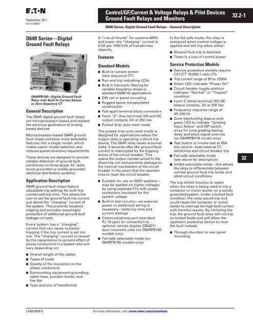
D64RPB100—Digital Ground Fault<br />
Relay with Built-In Current Sensor<br />
or Zero-Sequence CT<br />
General Description<br />
The D64R digital ground fault relays<br />
are microprocessor-based and replace<br />
the previous generation of analogbased<br />
devices.<br />
Microprocessor-based D64R ground<br />
fault relays combine more selectable<br />
features into a single model, which<br />
makes easier model selection and<br />
reduces spares inventory requirements.<br />
These devices are designed to provide<br />
reliable detection of ground fault<br />
conditions on three-phase AC resistance<br />
grounded or solidly grounded<br />
electrical distribution systems.<br />
Application Description<br />
D64R ground fault relays feature<br />
adjustable trip settings for both trip<br />
current and trip time. This allows the<br />
user to set the ground fault trip current<br />
just above the “charging” current of<br />
the system. This prevents nuisance<br />
tripping and provides meaningful<br />
protection of additional ground fault<br />
leakage currents.<br />
Every system has a “charging”<br />
current that can cause nuisance<br />
tripping if the trip current is set too<br />
low. The “charging” current is caused<br />
by the capacitance-to-ground effect of<br />
phase conductors in a system and will<br />
vary depending on:<br />
■ Overall length of the cables<br />
■ Types of loads<br />
■ Quality of the insulation on the<br />
phase conductors<br />
■ Surrounding equipment grounding,<br />
cable trays, junction boxes, and<br />
the like<br />
■ Type and size of transformer<br />
<strong>Control</strong>/<strong>GF</strong>/Current & <strong>Voltage</strong> <strong>Relays</strong> & <strong>Pilot</strong> Devices<br />
Ground Fault <strong>Relays</strong> and Monitors<br />
D64R Series, Digital Ground Fault <strong>Relays</strong>—General Description<br />
A “rule-of-thumb” for systems 600V<br />
and lower: the “charging” current is<br />
0.5A per 1000 kVA of transformer<br />
capacity.<br />
Features<br />
Standard Models<br />
■ Built-in current sensor<br />
(zero sequence CT)<br />
■ Run and trip indicating LEDs<br />
■ Built-in harmonic filtering for<br />
variable frequency drives or<br />
standard 50/60 Hz applications<br />
■ DIN rail or panel mounting<br />
■ Rugged epoxy encapsulated<br />
construction<br />
■ Pull-apart terminal block connectors<br />
■ Form “Z” (four terminal) NO and NC<br />
output contacts, 5A at 250 Vac<br />
■ Pulsed (trip) auto reset mode<br />
The pulsed (trip) auto reset mode is<br />
designed for applications where the<br />
output relay is operating a shunt trip<br />
device. The D64R relay resets automatically,<br />
3 seconds after the ground fault<br />
current is interrupted by the tripping<br />
action of the circuit breaker. This<br />
opens the output contact wired to the<br />
shunt trip coil and prevents damage to<br />
the internal mechanism of the circuit<br />
breaker in the event that the operator<br />
tries to reset the circuit breaker.<br />
■ Suitable for use on 600V systems—<br />
may be applied on higher voltages<br />
by using separate CTs with power<br />
conductors insulated for the<br />
system voltage<br />
■ Built-in test circuitry—no external<br />
power or additional wiring is<br />
necessary—tests trip time and<br />
current settings<br />
■ Communications port (standard<br />
RJ-10 jack) for connection to<br />
optional remote display (D64D1)<br />
door-mounted units (on D64RPB100<br />
models only)<br />
■ Fail-safe selectable mode (on<br />
D64RPB100 models only)<br />
CA08104001E For more information, visit: www.eaton.com/consultants<br />
In the fail-safe mode, the relay is<br />
energized when control voltage is<br />
applied and will trip when either:<br />
■ Ground fault trip is detected<br />
■ There is a loss of control power<br />
Service Protection Models<br />
■ Service protection models require<br />
C311CT 10,000:1 ratio CTs<br />
■ Trip current range of 50 to 1200A<br />
■ Green LED indicates “Power On”<br />
■ Circuit breaker toggle position<br />
indicates “Normal” or “Tripped”<br />
condition<br />
■ Form C (three terminal) NO-NC<br />
output contacts, 3A at 250 Vac<br />
■ Frequency response range of<br />
40–200 Hz<br />
■ Zone interlocking feature with<br />
green LED to indicate “Grading<br />
Input Active” and DIP switch<br />
array for zone grading backup<br />
delay and block signal override<br />
(on D64RPBH15 model only)<br />
■ Test button to invoke test at 20A<br />
trip current—tests external CT,<br />
electronics and circuit breaker trip<br />
■ Fail-safe selectable mode<br />
(see above for description)<br />
■ Inhibit selectable mode—this allows<br />
the relay to differentiate between<br />
normal ground fault trip levels and<br />
short-circuit conditions<br />
The trip inhibit function is useful<br />
when the relay is being used to trip a<br />
contactor or motor starter on a solidly<br />
grounded system. Under a bolted fault<br />
condition, the relay would trip and<br />
could cause the contactor or motor<br />
starter to interrupt the high fault current<br />
with harmful results. By inhibiting the<br />
trip, the ground fault relay will not trip<br />
on bolted faults and will allow the<br />
upstream protective device to clear<br />
the fault instead.<br />
■ Through-the-door or rear panel<br />
mounting<br />
32.2-1<br />
22<br />
23<br />
24<br />
25<br />
26<br />
27<br />
28<br />
29<br />
30<br />
31<br />
32<br />
33<br />
34<br />
35<br />
36<br />
37<br />
38<br />
39<br />
40<br />
41<br />
42<br />
43


