

Control/GF/Voltage Relays & Pilot - Eaton
Control/GF/Voltage Relays & Pilot - Eaton
Control/GF/Voltage Relays & Pilot - Eaton

Create successful ePaper yourself
Turn your PDF publications into a flip-book with our unique Google optimized e-Paper software.
32.2-2<br />
22<br />
23<br />
24<br />
25<br />
26<br />
27<br />
28<br />
29<br />
30<br />
31<br />
32<br />
33<br />
34<br />
35<br />
36<br />
37<br />
38<br />
39<br />
40<br />
41<br />
42<br />
43<br />
<strong>Control</strong>/<strong>GF</strong>/Current & <strong>Voltage</strong> <strong>Relays</strong> & <strong>Pilot</strong> Devices<br />
Ground Fault <strong>Relays</strong> and Monitors<br />
D64R Series—Digital Ground Fault <strong>Relays</strong><br />
Technical Data<br />
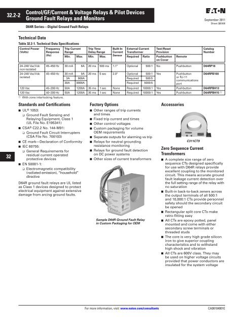
Table 32.2-1. Technical Data Specifications<br />
<strong>Control</strong> Power<br />
(Volts)<br />
September 2011<br />
Sheet 32008<br />
24–240 Vac/Vdc<br />
non-isolated<br />
45–450 Hz 30 mA 6A 20 ms 500 ms 1.1" Optional 500:1 No Pushbutton D64RP18<br />
24–240 Vac/Vdc 45–450 Hz 30 mA 9A 20 ms 5 sec 2.0" Optional 500:1 Yes Pushbutton D64RPB100<br />
isolated<br />
3A<br />
30A<br />
900A<br />
9000A<br />
Required<br />
Required<br />
500:5<br />
5000:5<br />
or RJ-11<br />
communications<br />
port<br />
120 Vac 45–200 Hz 50A 1200A 35 ms 1 sec None Required 10000:1 Yes Pushbutton D64RPBH13<br />
120 Vac 40–200 Hz 50A 1200A 35 ms 1 sec None Required 10000:1 Yes Pushbutton D64RPBH15<br />
� With zone interlocking feature.<br />
�<br />
Standards and Certifications<br />
■ UL ® 1053:<br />
Frequency<br />
Response<br />
(Hz)<br />
Trip Current<br />
Range<br />
❑ Ground Fault Sensing and<br />
Relaying Equipment, Class 1<br />
(UL File No. E195341)<br />
■ CSA ® C22.2 No. 144-M91:<br />
❑ Ground Fault Circuit Interrupters<br />
(CSA File No. 700103)<br />
■ CE mark—Declaration of Conformity<br />
■ IEC 60755:<br />
❑ General Requirements for<br />
residual current operated<br />
protective devices<br />
■ EN 50081-1:<br />
❑ Electromagnetic compatibility<br />
(radiated emission), “household”<br />
directive<br />
D64R ground fault relays are UL listed<br />
as Class 1 devices designed to protect<br />
electrical equipment against extensive<br />
damage from arcing ground faults.<br />
Trip Time<br />
Delay Range<br />
Built-In<br />
Current<br />
Sensor<br />
Factory Options<br />
External Current<br />
Transformer<br />
■ Other ranges of trip currents<br />
and times<br />
■ Fixed trip current and times<br />
■ Other control voltages<br />
■ Custom packaging for volume<br />
OEM requirements<br />
■ Separate outputs for alarming vs trip<br />
■ <strong>Relays</strong> for neutral grounding<br />
resistance monitoring<br />
■ <strong>Relays</strong> for ground fault detection<br />
on DC power systems<br />
■ Other sizes of current transformers<br />
Sample D64R Ground Fault Relay<br />
in Custom Packaging for OEM<br />
Test/Reset<br />
Provision<br />
Min. Max. Min. Max. Required Ratio Pushbutton<br />
on Cover<br />
Remote<br />
Accessories<br />
C311CT9<br />
Zero Sequence Current<br />
Transformers<br />
Catalog<br />
Number<br />
■ A complete size range of zero<br />
sequence CTs designed specifically<br />
for use with D64R relays provide<br />
excellent coupling to the monitored<br />
circuit. This means accurate ground<br />
fault leakage current detection over<br />
the full setting range of the relay with<br />
no saturation<br />
■ Built-in back-to-back zeners across<br />
the output terminals of all 500:1<br />
and 10,000:1 CTs provide personnel<br />
safety should the secondary circuit<br />
be opened<br />
■ Rectangular split core CTs make<br />
retro-fitting easy<br />
■ All CTs are epoxy potted, panel<br />
mounted and come with either<br />
secondary screw terminals or<br />
threaded studs<br />
■ The core is very high grade silicon<br />
iron to give superior coupling<br />
characteristics and to withstand<br />
high shock and vibration<br />
■ All CTs are 600V class. They may<br />
be used on higher voltage circuits<br />
provided that power conductors are<br />
insulated for the system voltage<br />
For more information, visit: www.eaton.com/consultants CA08104001E


