WARRANTY SSW-05 Plus - Dimotec
WARRANTY SSW-05 Plus - Dimotec
WARRANTY SSW-05 Plus - Dimotec

Create successful ePaper yourself
Turn your PDF publications into a flip-book with our unique Google optimized e-Paper software.
ENGLISH<br />
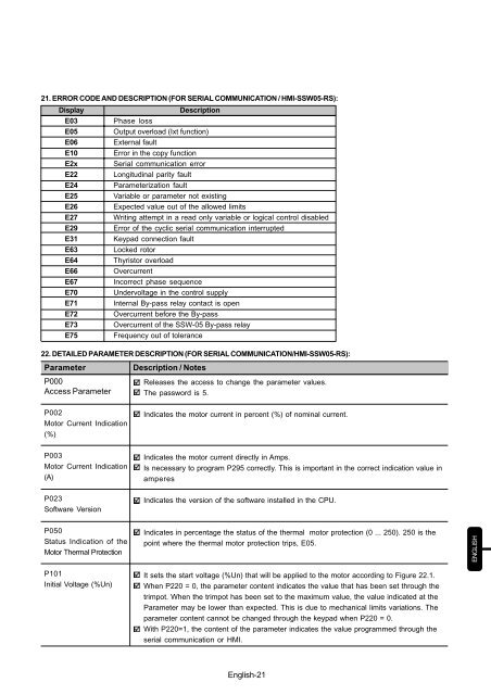
21. ERROR CODE AND DESCRIPTION (FOR SERIAL COMMUNICATION / HMI-<strong>SSW</strong><strong>05</strong>-RS):<br />
Display<br />
Description<br />
E03 Phase loss<br />
E<strong>05</strong> Output overload (Ixt function)<br />
E06 External fault<br />
E10 Error in the copy function<br />
E2x Serial communication error<br />
E22 Longitudinal parity fault<br />
E24 Parameterization fault<br />
E25 Variable or parameter not existing<br />
E26 Expected value out of the allowed limits<br />
E27 Writing attempt in a read only variable or logical control disabled<br />
E29 Error of the cyclic serial communication interrupted<br />
E31 Keypad connection fault<br />
E63 Locked rotor<br />
E64 Thyristor overload<br />
E66 Overcurrent<br />
E67 Incorrect phase sequence<br />
E70 Undervoltage in the control supply<br />
E71 Internal By-pass relay contact is open<br />
E72 Overcurrent before the By-pass<br />
E73 Overcurrent of the <strong>SSW</strong>-<strong>05</strong> By-pass relay<br />
E75 Frequency out of tolerance<br />
22. DETAILED PARAMETER DESCRIPTION (FOR SERIAL COMMUNICATION/HMI-<strong>SSW</strong><strong>05</strong>-RS):<br />
Parameter<br />
P000<br />
Access Parameter<br />
Description / Notes<br />
Releases the access to change the parameter values.<br />
The password is 5.<br />
P002<br />
Motor Current Indication<br />
(%)<br />
Indicates the motor current in percent (%) of nominal current.<br />
P003<br />
Motor Current Indication<br />
(A)<br />
Indicates the motor current directly in Amps.<br />
Is necessary to program P295 correctly. This is important in the correct indication value in<br />
amperes<br />
P023<br />
Software Version<br />
Indicates the version of the software installed in the CPU.<br />
P<strong>05</strong>0<br />
Status Indication of the<br />
Motor Thermal Protection<br />
Indicates in percentage the status of the thermal motor protection (0 ... 250). 250 is the<br />
point where the thermal motor protection trips, E<strong>05</strong>.<br />
P101<br />
Initial Voltage (%Un)<br />
It sets the start voltage (%Un) that will be applied to the motor according to Figure 22.1.<br />
When P220 = 0, the parameter content indicates the value that has been set through the<br />
trimpot. When the trimpot has been set to the maximum value, the value indicated at the<br />
Parameter may be lower than expected. This is due to mechanical limits variations. The<br />
parameter content cannot be changed through the keypad when P220 = 0.<br />
With P220=1, the content of the parameter indicates the value programmed through the<br />
serial communication or HMI.<br />
English-21