- Page 2 and 3: WARNINGFAILURE TO FOLLOW SAFE OPERA
- Page 5 and 6: RSection 11.1 IntroductionYour mowe
- Page 7 and 8: RSection 22.1 IntroductionYour mowe
- Page 9 and 10: RSection 23.4.5.6.To prevent tippin
- Page 11: RSection 22.3.4.5.Remove the hairpi
- Page 15 and 16: RSection 3Travel Speed:Forward.....
- Page 17 and 18: RSection 46. Fuse Holders (Figure 4
- Page 19 and 20: RSection 4Reverse TravelCautionDise
- Page 21 and 22: 5RSection 44.11 MOVING MOWER WITH E
- Page 23 and 24: RSection 5TROUBLESHOOTING CUTTING C
- Page 25 and 26: RSection 5TROUBLESHOOTING CUTTING C
- Page 27 and 28: RSection 6Neutral AdjustmentTrackin
- Page 29 and 30: RSection 6Cutter Deck PitchThe pitc
- Page 31 and 32: RSection 61 231 23AAMounting SlotCu
- Page 33 and 34: RSection 7MAINTENANCE CHART - RECOM
- Page 35 and 36: RSection 77.3 Hydraulic SystemA. Ch
- Page 37 and 38: RSection 72.3.4.5.6.7.8.9.Use only
- Page 39: RSection 77.8 DRIVE BELTSB. Blade S
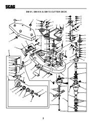
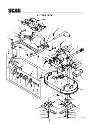
- Page 42 and 43: R Section848V & 52V CUTTER DECKS551
- Page 44 and 45: R Section861V CUTTER DECK2414521832
- Page 46 and 47: R Section8CUTTER DECK CONTROLS32451
- Page 48 and 49: R Section8SHEET METAL COMPONENTS233
- Page 50 and 51: R Section8STC FIXED ROLL-OVER PROTE
- Page 52 and 53: R Section8STC FOLDABLE ROLL-OVER PR
- Page 54 and 55: R Section8DRIVE SYSTEM COMPONENTS22
- Page 56 and 57: R Section8ENGINE & ATTACHING PARTS5
- Page 58 and 59: R Section8STEERING COMPONENTS123839
- Page 60 and 61: R Section8BRAKE COMPONENTS4 5 18768
- Page 62 and 63:
R Section84E218 19G1245 463 5533 47
- Page 64 and 65:
60R Section 8ELECTRICAL SYSTEMSTC 2
- Page 66 and 67:
R Section8BDP-10A HYDRAULIC PUMP AS
- Page 68 and 69:
R Section8REPLACEMENT DECALS AND IN
- Page 70 and 71:
R Section8ELECTRICAL SCHEMATICBRIGG
- Page 73 and 74:
Sección 7-NOTA-Asegúrese que la c
- Page 75 and 76:
Sección 7ADVERTENCIA:LAS BATERÍAS
- Page 77 and 78:
Sección 77.5 SISTEMA DE COMBUSTIBL
- Page 79 and 80:
Sección 77.3 SISTEMA HIDRÁULICOA.
- Page 81 and 82:
Sección 7TABLA DE MANTENIMIENTO -
- Page 83 and 84:
Sección 61 231 23AAAjuste del defl
- Page 85 and 86:
Sección 6AFLOJEAQUÍCUT TINGHEIGHT
- Page 87 and 88:
Sección 6Ajuste de alineaciónPREC
- Page 89 and 90:
Sección 6AJUSTES6.1 AJUSTE DEL FRE
- Page 91 and 92:
Sección 5SOLUCIÓN DE FALLAS (CONT
- Page 93 and 94:
X1 1/42 1/23 1/24 1/4CUT TINGHEIGHT
- Page 95 and 96:
Sección 44. Puede producirse una p
- Page 97 and 98:
Sección 44.5 DESPLAZAMIENTO EN EL
- Page 99 and 100:
Sección 45. Horómetro (Figura 4-1
- Page 101 and 102:
Sección 33.3 TRACTOR (CONTINUACIÓ
- Page 103 and 104:
2.7 CALCOMANÍAS INSTRUCTIVAS Y DE
- Page 105 and 106:
Sección 2La exposición potencial
- Page 107 and 108:
Sección 214. Desconecte la potenci
- Page 109 and 110:
Sección 23. NO permita que los ni
- Page 111 and 112:
SÍMBOLO DESCRIPCIÓN SÍMBOLO DESC
- Page 113 and 114:
Sección 1INFORMACIÓN GENERAL1.1 I
- Page 115 and 116:
TABLA DE CONTENIDOTEMA PÁGINASecci
- Page 117:
© 2007SCAG POWER EQUIPMENTDIVISION