You also want an ePaper? Increase the reach of your titles
YUMPU automatically turns print PDFs into web optimized ePapers that Google loves.
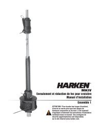
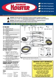
Preassembly<br />
Pin-to-Pin Headstay Length (See Pg 8)<br />
Longueur axe à axe de l'étai (Voir Pg 8)<br />
Bolzen-Bolzen-Mass Anzahl des Vorstages (s.S. 8)<br />
Lunghezza perno-a-perno dello strallo (vedi p. 8)<br />
Number 7" (178 mm) Connectors<br />
Nombre de connecteurs de 152 mm utilisés<br />
Verbinder<br />
Numero di estrusi da 152 mm usati<br />
24'8" to 25'4" (7.518 m to 7.722 m) 3<br />
25'5" to 32'4" (7.747 m to 9.855 m) 4<br />
32'5" to 39'4" (9.88 m to 11.989 m) 5<br />
39'5" to 46'4" (12.014 m to 14.122 m) 6<br />
46'5" to 52'7" (14.148 m to 16.027 m) 7*<br />
Number 7' (2.13 m)Foils Used<br />
Nombre de profils de 2.13 m utilisés<br />
Verbinders<br />
Numero di estrusi da 2.13 m usati<br />
24'9" to 31'8" (7.54 m to 9.652 m) 3<br />
31'9" to 38'8" (9.667 m to 11.786 m) 4<br />
38'9" to 45'8" (11.811 m to 13.919 m) 5<br />
45'9" to 52'8" (13.945 m to 16.053 m) 6*<br />
How many foils and connectors • Stringing connectors<br />
■ How Many Connectors?<br />
Use the chart at left to determine the proper number<br />
of 7" (178 mm) connectors for your headstay.<br />
Every unit uses one 8 7 /8" (225 mm) bottom connector<br />
in addition to the number of 7" (178 mm) connectors<br />
shown at left.<br />
*One additional connector required; order part 810<br />
■ How Many Foils?<br />
Use the chart at left to determine the proper number<br />
of 7' (2.13 m) foils for your headstay.<br />
The variable length top foil is cut from one of the 7'<br />
(2.13 m) foils and is used in addition to the number<br />
of foils shown at left.<br />
*One additional foil required; order part 807<br />
■ Stringing Connectors<br />
After the headstay has been cut to length, but before<br />
the threaded stud is attached, the proper number of<br />
connectors must be placed on the headstay in the<br />
correct order.<br />
Every unit uses a top foil trim cap.<br />
Every unit uses a number of 7" (178 mm) connetors<br />
which varies according to the length of the headstay<br />
and is determined by consulting the chart above.<br />
Every unit uses one 8 7 /8" (225 mm) bottom connector.<br />
Slide the trim cap onto the stay so that the open end<br />
faces down.<br />
Slide the proper number of 7" (178 mm) connectors<br />
onto the headstay.<br />
Slide the 8 7 /8" (225 mm) bottom connector onto the<br />
headstay so that it is closest to the bottom of the<br />
headstay.<br />
Have the wire swaged by a reputable rigger.<br />
Norseman/Sta-Lok Instructions<br />
Because Norseman and Sta-Lok studs are applied to the headstay<br />
wire after the foil is built, it is not necessary to place the<br />
connectors or trim cap on the wire at this time.<br />
Norseman and Sta-Lok units require the same number of foils<br />
and connectors as shown above. Identify the parts you need<br />
and set them aside at this time.<br />
Rod Instructions<br />
Rod installations are identical to swaged wire at this point<br />
except that the rod adapter stud is “coldheaded” to the rod<br />
rather than swaged on.<br />
If you ship a rod headstay to a service center do not coil<br />
tighter than 200 times the rod's diameter.<br />
November 2001 Unit 1 MKIII 11