Gasbrenner Forced draught gas burners Brûleurs ... - Riello Burners
Gasbrenner Forced draught gas burners Brûleurs ... - Riello Burners
Gasbrenner Forced draught gas burners Brûleurs ... - Riello Burners

You also want an ePaper? Increase the reach of your titles
YUMPU automatically turns print PDFs into web optimized ePapers that Google loves.
Montage und Bedienungs Anleitung<br />
Installation, use and maintenance instructions<br />
Manuel d»entretien<br />
D<br />
GB<br />
F<br />
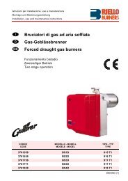
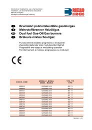
Gebläse - <strong>Gasbrenner</strong><br />
<strong>Forced</strong> <strong>draught</strong> <strong>gas</strong> <strong>burners</strong><br />
Brûleurs gaz à air soufflé<br />
Zweistufig gleitender Betrieb<br />
Progressive two-stage operation<br />
Fonctionnement à 2 allures progressives<br />
CODE<br />
MODELL<br />
MODEL - MODELE<br />
TYP - TYPE<br />
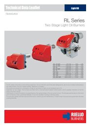
3752118 GAS 3/2 521 T1<br />
3752218 GAS 4/2 522 T1<br />
3752318 GAS 5/2 523 T1<br />
3752418 GAS 6/2 524 T1<br />
3752518 GAS 7/2 525 T1<br />
2915916 (2)
D<br />
INHALT<br />
GB<br />
CONTENTS<br />
TECHNISCHE ANGABEN. . . . . . . . . . . . . . . . . . . . . . . . . Seite 3<br />
Zubehör . . . . . . . . . . . . . . . . . . . . . . . . . . . . . . . . . . . . . . . . . . . . 6<br />
Brennerbeschreibung . . . . . . . . . . . . . . . . . . . . . . . . . . . . . . . . . . 8<br />
Verpackung - Gewicht . . . . . . . . . . . . . . . . . . . . . . . . . . . . . . . . . 8<br />
Abmessungen . . . . . . . . . . . . . . . . . . . . . . . . . . . . . . . . . . . . . . . 8<br />
Ausstattung . . . . . . . . . . . . . . . . . . . . . . . . . . . . . . . . . . . . . . . . . 8<br />
Regelbereiche . . . . . . . . . . . . . . . . . . . . . . . . . . . . . . . . . . . . . . 10<br />
Handelsübliche Kessel . . . . . . . . . . . . . . . . . . . . . . . . . . . . . . . . 10<br />
Prüfkessel. . . . . . . . . . . . . . . . . . . . . . . . . . . . . . . . . . . . . . . . . . 12<br />
Gasdruck . . . . . . . . . . . . . . . . . . . . . . . . . . . . . . . . . . . . . . . . . . 12<br />
INSTALLATION . . . . . . . . . . . . . . . . . . . . . . . . . . . . . . . . . . . . . 14<br />
Kesselplatte . . . . . . . . . . . . . . . . . . . . . . . . . . . . . . . . . . . . . . . . 14<br />
Flammrohrlänge . . . . . . . . . . . . . . . . . . . . . . . . . . . . . . . . . . . . . 14<br />
Befestigung des Brenners am Heizkessel . . . . . . . . . . . . . . . . . 14<br />
Einstellung des Flammkopfs . . . . . . . . . . . . . . . . . . . . . . . . . . . 16<br />
Gaszuleitung . . . . . . . . . . . . . . . . . . . . . . . . . . . . . . . . . . . . . . . 18<br />
Elektroanlage . . . . . . . . . . . . . . . . . . . . . . . . . . . . . . . . . . . . . . . 20<br />
Einstellungen vor der Zündung . . . . . . . . . . . . . . . . . . . . . . . . . 26<br />
Stellantrieb . . . . . . . . . . . . . . . . . . . . . . . . . . . . . . . . . . . . . . . . . 26<br />
Anfahren des Brenners . . . . . . . . . . . . . . . . . . . . . . . . . . . . . . . 28<br />
Zündung des Brenners. . . . . . . . . . . . . . . . . . . . . . . . . . . . . . . . 28<br />
Brennereinstellung: . . . . . . . . . . . . . . . . . . . . . . . . . . . . . . . . . . 30<br />
1 - Zündleistung . . . . . . . . . . . . . . . . . . . . . . . . . . . . . . . . . . . . . 30<br />
2 - Leistung auf 1. Stufe . . . . . . . . . . . . . . . . . . . . . . . . . . . . . . . 30<br />
3 - Leistung auf 2. Stufe . . . . . . . . . . . . . . . . . . . . . . . . . . . . . . . 32<br />
4 - Luft-Druckwächter . . . . . . . . . . . . . . . . . . . . . . . . . . . . . . . . . 32<br />
5 - Gas-Minimaldruckwächter. . . . . . . . . . . . . . . . . . . . . . . . . . . 32<br />
Flammenüberwachung. . . . . . . . . . . . . . . . . . . . . . . . . . . . . . . . 32<br />
Brennerbetrieb . . . . . . . . . . . . . . . . . . . . . . . . . . . . . . . . . . . . . . 34<br />
Endkontrollen . . . . . . . . . . . . . . . . . . . . . . . . . . . . . . . . . . . . . . . 36<br />
Wartung . . . . . . . . . . . . . . . . . . . . . . . . . . . . . . . . . . . . . . . . . . . 36<br />
Störungen - Ursachen - Abhilfen . . . . . . . . . . . . . . . . . . . . . . . . 38<br />
Diagnostik Betriebsablauf. . . . . . . . . . . . . . . . . . . . . . . . . . . . . . 41<br />
Diagnostik Betriebsstörungen . . . . . . . . . . . . . . . . . . . . . . . . . . 41<br />
Anmerkung<br />
Die Zeichnungen, auf die im Text Bezug genommen wird, werden<br />
folgendermaßen bezeichnet:<br />
1)(A) = Detail 1 der Zeichnung A auf der gleichen Textseite;<br />
1)(A)S.6 = Detail 1 der Zeichnung A auf Seite 6.<br />
TECHNICAL DATA . . . . . . . . . . . . . . . . . . . . . . . . . . . . . . . page 4<br />
Accessories. . . . . . . . . . . . . . . . . . . . . . . . . . . . . . . . . . . . . . . . . . 7<br />
Burner description . . . . . . . . . . . . . . . . . . . . . . . . . . . . . . . . . . . . . 9<br />
Packaging - Weight . . . . . . . . . . . . . . . . . . . . . . . . . . . . . . . . . . . . 9<br />
Max. dimensions . . . . . . . . . . . . . . . . . . . . . . . . . . . . . . . . . . . . . . 9<br />
Standard equipment . . . . . . . . . . . . . . . . . . . . . . . . . . . . . . . . . . . 9<br />
Firing rates . . . . . . . . . . . . . . . . . . . . . . . . . . . . . . . . . . . . . . . . . 11<br />
Commercial boiler . . . . . . . . . . . . . . . . . . . . . . . . . . . . . . . . . . . . 11<br />
Test boilers . . . . . . . . . . . . . . . . . . . . . . . . . . . . . . . . . . . . . . . . . 13<br />
Gas pressure. . . . . . . . . . . . . . . . . . . . . . . . . . . . . . . . . . . . . . . . 13<br />
INSTALLATION . . . . . . . . . . . . . . . . . . . . . . . . . . . . . . . . . . . . . 15<br />
Boiler plate . . . . . . . . . . . . . . . . . . . . . . . . . . . . . . . . . . . . . . . . . 15<br />
Blast tube length . . . . . . . . . . . . . . . . . . . . . . . . . . . . . . . . . . . . 15<br />
Securing the burner to the boiler. . . . . . . . . . . . . . . . . . . . . . . . . 15<br />
Setting the combustion head . . . . . . . . . . . . . . . . . . . . . . . . . . . 17<br />
Gas line . . . . . . . . . . . . . . . . . . . . . . . . . . . . . . . . . . . . . . . . . . . . 19<br />
Electrical system . . . . . . . . . . . . . . . . . . . . . . . . . . . . . . . . . . . . . 21<br />
Adjustments before firing . . . . . . . . . . . . . . . . . . . . . . . . . . . . . . 27<br />
Servomotor . . . . . . . . . . . . . . . . . . . . . . . . . . . . . . . . . . . . . . . . . 27<br />
Burner starting. . . . . . . . . . . . . . . . . . . . . . . . . . . . . . . . . . . . . . . 29<br />
Burner firing. . . . . . . . . . . . . . . . . . . . . . . . . . . . . . . . . . . . . . . . . 29<br />
Burner calibration: . . . . . . . . . . . . . . . . . . . . . . . . . . . . . . . . . . . . 31<br />
1 - Firing output . . . . . . . . . . . . . . . . . . . . . . . . . . . . . . . . . . . . . . 31<br />
2 - 1st stage output . . . . . . . . . . . . . . . . . . . . . . . . . . . . . . . . . . . 31<br />
3 - 2nd stage output . . . . . . . . . . . . . . . . . . . . . . . . . . . . . . . . . . 33<br />
4 - Air pressure switch. . . . . . . . . . . . . . . . . . . . . . . . . . . . . . . . . 33<br />
5 - Minimum <strong>gas</strong> pressure switch . . . . . . . . . . . . . . . . . . . . . . . . 33<br />
Flame present check. . . . . . . . . . . . . . . . . . . . . . . . . . . . . . . . . . 33<br />
Burner operation . . . . . . . . . . . . . . . . . . . . . . . . . . . . . . . . . . . . . 35<br />
Final checks . . . . . . . . . . . . . . . . . . . . . . . . . . . . . . . . . . . . . . . . 37<br />
Maintenance . . . . . . . . . . . . . . . . . . . . . . . . . . . . . . . . . . . . . . . . 37<br />
Fault - Probable cause - Suggested remedy. . . . . . . . . . . . . . . . 39<br />
Burner start-up cycle diagnostics . . . . . . . . . . . . . . . . . . . . . . . . 42<br />
Operating fault diagnostics . . . . . . . . . . . . . . . . . . . . . . . . . . . . . 42<br />
N.B.<br />
Figures mentioned in the text are identified as follows:<br />
1)(A) =part 1 of figure A, same page as text;<br />
1)(A)p.6 =part 1 of figure A, page number 6.<br />
F<br />
INDEX<br />
DONNÉES TECHNIQUES . . . . . . . . . . . . . . . . . . . . . . . . . page 5<br />
Accesoires . . . . . . . . . . . . . . . . . . . . . . . . . . . . . . . . . . . . . . . . . . 7<br />
Description brûleur . . . . . . . . . . . . . . . . . . . . . . . . . . . . . . . . . . . . 9<br />
Emballage - Poids . . . . . . . . . . . . . . . . . . . . . . . . . . . . . . . . . . . . 9<br />
Encombrement . . . . . . . . . . . . . . . . . . . . . . . . . . . . . . . . . . . . . . . 9<br />
Equipement standard . . . . . . . . . . . . . . . . . . . . . . . . . . . . . . . . . . 9<br />
Plages de puissance . . . . . . . . . . . . . . . . . . . . . . . . . . . . . . . . . 11<br />
Chaudières commerciales . . . . . . . . . . . . . . . . . . . . . . . . . . . . . 11<br />
Chaudière d»essai. . . . . . . . . . . . . . . . . . . . . . . . . . . . . . . . . . . . 13<br />
Pression du gaz . . . . . . . . . . . . . . . . . . . . . . . . . . . . . . . . . . . . . 13<br />
INSTALLATION . . . . . . . . . . . . . . . . . . . . . . . . . . . . . . . . . . . . . 15<br />
Plaque chaudière . . . . . . . . . . . . . . . . . . . . . . . . . . . . . . . . . . . . 15<br />
Longueur buse . . . . . . . . . . . . . . . . . . . . . . . . . . . . . . . . . . . . . 15<br />
Fixation du brûleur à la chaudière . . . . . . . . . . . . . . . . . . . . . . . 15<br />
Réglage tête de combustion. . . . . . . . . . . . . . . . . . . . . . . . . . . . 17<br />
Ligne alimentation gaz . . . . . . . . . . . . . . . . . . . . . . . . . . . . . . . . 19<br />
Installation électrique . . . . . . . . . . . . . . . . . . . . . . . . . . . . . . . . . 21<br />
Réglages avant l»allumage . . . . . . . . . . . . . . . . . . . . . . . . . . . . . 27<br />
Servomoteur. . . . . . . . . . . . . . . . . . . . . . . . . . . . . . . . . . . . . . . . 27<br />
Démarrage brûleur . . . . . . . . . . . . . . . . . . . . . . . . . . . . . . . . . . . 29<br />
Allumage brûleur . . . . . . . . . . . . . . . . . . . . . . . . . . . . . . . . . . . . 29<br />
Réglage brûleur:. . . . . . . . . . . . . . . . . . . . . . . . . . . . . . . . . . . . . 31<br />
1 - Puissance à l»allumage . . . . . . . . . . . . . . . . . . . . . . . . . . . . . 31<br />
2 - Puissance en 1ère allure. . . . . . . . . . . . . . . . . . . . . . . . . . . . 31<br />
3 - Puissance en 2ème allure. . . . . . . . . . . . . . . . . . . . . . . . . . . 33<br />
4 - Pressostat de l»air . . . . . . . . . . . . . . . . . . . . . . . . . . . . . . . . . 33<br />
5 - Pressostat gaz seuil minimum . . . . . . . . . . . . . . . . . . . . . . . 33<br />
Contrôle présence flamme . . . . . . . . . . . . . . . . . . . . . . . . . . . . . 33<br />
Fonctionnement brûleur . . . . . . . . . . . . . . . . . . . . . . . . . . . . . . . 35<br />
Contrôles finaux . . . . . . . . . . . . . . . . . . . . . . . . . . . . . . . . . . . . . 37<br />
Entretien . . . . . . . . . . . . . . . . . . . . . . . . . . . . . . . . . . . . . . . . . . . 37<br />
Inconvénients - Causes - Remèdes . . . . . . . . . . . . . . . . . . . . . . 40<br />
Diagnostics cycle de démarrage . . . . . . . . . . . . . . . . . . . . . . . . 43<br />
Diagnostics mauvais fonctionnement. . . . . . . . . . . . . . . . . . . . . 43<br />
Attention<br />
Les figures rappelées dans le texte sont ainsi indiquées:<br />
1)(A) = Détail 1 de la figure A dans la même page du texte;<br />
1)(A)p.6 = Détail 1 de la figure A page 6.<br />
D<br />
GB<br />
F<br />
In Konformität mit der Wirkungsgradrichtlinie 92/42/<br />
EWG müssen die Anbringung des Brenners am Heizkessel,<br />
die Einstellung und die Inbetriebnahme unter<br />
Beachtung der Betriebsanleitung der Heizkessels<br />
ausgeführt werden, einschließlich Kontrolle der Konzentration<br />
von CO und CO 2 in den Ab<strong>gas</strong>en, ihrer<br />
Temperatur und der mittlenen Kesseltemperatur.<br />
In conformity with Efficiency Directive 92/42/EEC the<br />
application of the burner on the boiler, adjustment<br />
and testing must be carried out observing the instruction<br />
manual of the boiler, including verification of the<br />
CO and CO 2 concentration in the flue <strong>gas</strong>es, their<br />
temperatures and the average temperature of the<br />
water in the boiler.<br />
Conformément à la Directive rendement 92/42/CEE,<br />
suivre les indications du manuel de la chaudière pour<br />
monter le brûleur, effectuer le réglage et l»essai, contrôler<br />
la concentration de CO et CO 2 , dans les<br />
fumées, leur température et celle moyenne de l»eau<br />
de la chaudière.<br />
2
TECHNISCHE ANGABEN<br />
D<br />
MODELL GAS 3/2 GAS 4/2 GAS 5/2 GAS 6/2 GAS 7/2<br />
TYP 521 T1 522 T1 523 T1 524 T1 525 T1<br />
LEISTUNG (1) 2. Stufe kW<br />
Mcal/h<br />
1. Stufe kW<br />
Mcal/h<br />
BRENNSTOFF<br />
- Unterer Heizwert Hu kWh/Nm 3<br />
Mcal/Nm 3 10<br />
8,6<br />
130 - 350<br />
112 - 301<br />
80 - 175<br />
69 - 150<br />
180 - 470<br />
155 - 404<br />
120 - 235<br />
104 - 202<br />
320 - 660<br />
275 - 568<br />
155 - 330<br />
133 - 284<br />
520 - 1050<br />
447 - 903<br />
300 - 520<br />
258 - 447<br />
800 - 1760<br />
688 - 1514<br />
(1) Bezugsbedingungen: Raumtemperatur 20°C - Barometrischer Druck 1000 mbar - Höhe 100 m ü.d.M.<br />
(2) Druck am Anschluß 12)(A)S.8 bei druckloser Brennkammer, geöffneter Gasscheibe 2)(B)S.16 und bei Höchstleistung des Brenners.<br />
400 - 880<br />
344 - 757<br />
ERDGAS: G20 - G21 - G22 - G23 - G25<br />
G20 G25 G20 G25 G20 G25 G20 G25 G20 G25<br />
8,6<br />
7,4<br />
- Reindichte kg/Nm 3 0,71 0,78 0,71 0,78 0,71 0,78 0,71 0,78 0,71 0,78<br />
- Höchstdruchsatz Nm 3 /h 35 41 47 54 66 77 105 122 176 205<br />
- Druck bei Höchstdruchsatz (2) mbar 11,1 16,4 9,8 14,5 9,8 14,5 12,3 18,2 14,5 21,4<br />
BETRIEB<br />
• Aussetzend (min. 1 Halt in 24 Stunden)<br />
• Zweistufig (hohe und niedrige Flamme) - einsufig (alles - nichts)<br />
STANDARDEINSATZ<br />
Heizkessel: mit Wasser, Dampf, diathermischem Öl<br />
RAUMTEMPERATUR °C 0 - 40<br />
TEMPERATUR VERBRENNUNGSLUFT °C max 60<br />
ELEKTRISCHE SPEISUNG<br />
ELEKTROMOTOR<br />
V<br />
Hz<br />
rpm<br />
W<br />
V<br />
A<br />
MOTORKONDENSATOR µF<br />
V<br />
ZÜNDTRANSFORMATOR<br />
V1 - V2<br />
I1 - I2<br />
230 ~ +/-10%<br />
50 - einphasing<br />
2750<br />
250<br />
220 - 240<br />
1,8<br />
8<br />
450/500<br />
10<br />
8,6<br />
8,6<br />
7,4<br />
2810<br />
370<br />
220 - 240<br />
2,9<br />
12,5<br />
400/450<br />
10<br />
8,6<br />
8,6<br />
7,4<br />
10<br />
8,6<br />
8,6<br />
7,4<br />
230 - 400 mit Nulleiter ~ +/-10%<br />
50 - dreiphasing<br />
2870<br />
750<br />
220/240-380/415<br />
2,85 - 1,65<br />
230 V - 1 x 8 kV<br />
1,8 A - 30 mA<br />
2840<br />
1500<br />
220/240-380/415<br />
5,9 - 3,4<br />
10<br />
8,6<br />
8,6<br />
7,4<br />
2840<br />
3000<br />
220/240-380/415<br />
10,9 - 6,3<br />
ELEKTRISCHE LEISTUNGSAUFNAHME W max 400 540 850 1700 3400<br />
SCHUTZART IP 40<br />
CE - NORMGERECHT 90/396 - 89/336 - 73/23 - 92/42<br />
TYPPRÜFUNG CE 0085AQ0707<br />
LAND<br />
IT - AT - GR - DK - FI - SE<br />
ES - GB - IE - PT<br />
NL<br />
FR<br />
GERÄTEKATEGORIE<br />
II 2H3B / P<br />
II 2H3P<br />
II 2L3B / P<br />
II 2Er3P<br />
DE II 2ELL3B /P<br />
BE<br />
I 2E(R)B, I 3P<br />
LU II 2E3B /P<br />
Wichtiger Hinweis:<br />
Der Installateur haftet für den eventuellen Zusatz von Sicherheitsteilen, die nicht in dieser Betriebsanleitung vorgesehen sind.<br />
3
TECHNICAL DATA<br />
GB<br />
MODEL GAS 3/2 GAS 4/2 GAS 5/2 GAS 6/2 GAS 7/2<br />
TYPE 521 T1 522 T1 523 T1 524 T1 525 T1<br />
OUTPUT (1) 2nd stage kW 130 - 350 180 - 470 320 - 660 520 - 1050 800 - 1760<br />
Mcal/h<br />
112 - 301 155 - 404 275 - 568 447 - 903 688 - 1514<br />
1st stage kW<br />
Mcal/h<br />
80 - 175<br />
69 - 150<br />
120 - 235<br />
104 - 202<br />
155 - 330<br />
133 - 284<br />
300 - 520<br />
258 - 447<br />
400 - 880<br />
344 - 757<br />
FUEL<br />
NATURAL GAS: G20 - G21 - G22 - G23 - G25<br />
G20 G25 G20 G25 G20 G25 G20 G25 G20 G25<br />
- Net calorific value kWh/Nm 3<br />
Mcal/Nm 3 10<br />
8,6<br />
8,6<br />
7,4<br />
- Absolute density kg/Nm 3 0,71 0,78 0,71 0,78 0,71 0,78 0,71 0,78 0,71 0,78<br />
- Max delivery Nm 3 /h 35 41 47 54 66 77 105 122 176 205<br />
- Pressure at maximum delivery (2) mbar 11,1 16,4 9,8 14,5 9,8 14,5 12,3 18,2 14,5 21,4<br />
OPERATION<br />
• Intermittent (min. 1 stop in 24 hours)<br />
• Two-stage (high and low flame) and single-stage (all - nothing)<br />
STANDARD APPLICATIONS<br />
Boilers: water, steam, diathermic oil<br />
AMBIENT TEMPERATURE °C 0 - 40<br />
COMBUSTION AIR TEMPERATURE °C max 60<br />
ELECTRICAL SUPPLY<br />
ELECTRIC MOTOR<br />
V<br />
Hz<br />
rpm<br />
W<br />
V<br />
A<br />
MOTOR CAPACITOR µF<br />
V<br />
IGNITION TRANSFORMER<br />
V1 - V2<br />
I1 - I2<br />
230 ~ +/-10%<br />
50 - single-phase<br />
2750<br />
250<br />
220 - 240<br />
1,8<br />
8<br />
450/500<br />
(1) Reference conditions: Ambient temperature 20 ÈC - Barometric pressure 1000 mbar - Altitude 100 m a.s.l.<br />
(2) Pressure at test point 12)(A)p.8, with zero pressure in the combustion chamber, with open <strong>gas</strong> ring 2)(B)p.16 and maximum burner output.<br />
10<br />
8,6<br />
8,6<br />
7,4<br />
2810<br />
370<br />
220 - 240<br />
2,9<br />
12,5<br />
400/450<br />
10<br />
8,6<br />
8,6<br />
7,4<br />
10<br />
8,6<br />
8,6<br />
7,4<br />
230 - 400 with neutral ~ +/-10%<br />
50 - three-phase<br />
2870<br />
750<br />
220/240-380/415<br />
2,85 - 1,65<br />
230 V - 1 x 8 kV<br />
1,8 A - 30 mA<br />
2840<br />
1500<br />
220/240-380/415<br />
5,9 - 3,4<br />
10<br />
8,6<br />
8,6<br />
7,4<br />
2840<br />
3000<br />
220/240-380/415<br />
10,9 - 6,3<br />
ELECTRICAL POWER CONSUMPTION W max 400 540 850 1700 3400<br />
ELECTRICAL PROTECTION IP 40<br />
IN CONFORMITY WITH EEC DIRECTIVES 90/396 - 89/336 - 73/23 - 92/42<br />
APPROVAL CE 0085AQ0707<br />
COUNTRY<br />
IT - AT - GR - DK - FI - SE<br />
ES - GB - IE - PT<br />
NL<br />
FR<br />
CATEGORY<br />
II 2H3B / P<br />
II 2H3P<br />
II 2L3B / P<br />
II 2Er3P<br />
DE II 2ELL3B /P<br />
BE<br />
I 2E(R)B, I 3P<br />
LU II 2E3B /P<br />
Important:<br />
The installer is responsible for the addition of any safety device not forseen in the present manual.<br />
4
DONNEES TECHNIQUES<br />
F<br />
MODELE GAS 3/2 GAS 4/2 GAS 5/2 GAS 6/2 GAS 7/2<br />
TYPE 521 T1 522 T1 523 T1 524 T1 525 T1<br />
PUISSANCE (1) 2ème<br />
allure<br />
COMBUSTIBLE<br />
1ère<br />
allure<br />
kW 130 - 350<br />
Mcal/h<br />
112 - 301<br />
kW<br />
Mcal/h<br />
- pouvoir calorifique inférieur kWh/Nm 3<br />
Mcal/Nm 3 10<br />
8,6<br />
80 - 175<br />
69 - 150<br />
180 - 470<br />
155 - 404<br />
120 - 235<br />
104 - 202<br />
320 - 660<br />
275 - 568<br />
155 - 330<br />
133 - 284<br />
520 - 1050<br />
447 - 903<br />
300 - 520<br />
258 - 447<br />
800 - 1760<br />
688 - 1514<br />
400 - 880<br />
344 - 757<br />
GAZ NATUREL: G20 - G21 - G22 - G23 - G25<br />
G20 G25 G20 G25 G20 G25 G20 G25 G20 G25<br />
8,6<br />
7,4<br />
- densité absolue kg/Nm 3 0,71 0,78 0,71 0,78 0,71 0,78 0,71 0,78 0,71 0,78<br />
- débit maximum Nm 3 /h 35 41 47 54 66 77 105 122 176 205<br />
- pression au débit max. (2) mbar 11,1 16,4 9,8 14,5 9,8 14,5 12,3 18,2 14,5 21,4<br />
FONCTIONNEMENT<br />
• Intermittent (1 arrêt min en 24 heures)<br />
• 2 allures (flamme haute rt basse) et une allure (tout - rien)<br />
EMPLOI STANDARD<br />
Chaudières à eau, à vapeur, à huile diathermique<br />
TEMPERATURE AMBIANTE °C 0 - 40<br />
TEMPERATURE AIR COMBURANT °C max 60<br />
ALIMENTATION ELECTRIQUE<br />
MOTEUR ELECTRIQUE<br />
V<br />
Hz<br />
rpm<br />
W<br />
V<br />
A<br />
CONDENSATEUR MOTEUR µF<br />
V<br />
TRASFORMATEUR D»ALLUMAGE<br />
V1 - V2<br />
I1 - I2<br />
230 ~ +/-10%<br />
50 - monophasée<br />
2750<br />
250<br />
220 - 240<br />
1,8<br />
8<br />
450/500<br />
(1) Conditions de référence: Température ambiante 20°C - Pression barométrique 1000 mbar - Altitude 100 m au-dessus du niveau de la mer.<br />
(2) Pression à la prise 12)(A)p.8, avec une pression nulle dans la chambre de combustion, avec la bague du gaz 2)(B)p.16 ouverte et à la puissance<br />
maximum du brûleur.<br />
10<br />
8,6<br />
8,6<br />
7,4<br />
2810<br />
370<br />
220 - 240<br />
2,9<br />
12,5<br />
400/450<br />
10<br />
8,6<br />
8,6<br />
7,4<br />
10<br />
8,6<br />
8,6<br />
7,4<br />
230 - 400 mit Nulleiter ~ +/-10%<br />
50 - triphasée<br />
2870<br />
750<br />
220/240-380/415<br />
2,85 - 1,65<br />
230 V - 1 x 8 kV<br />
1,8 A - 30 mA<br />
2840<br />
1500<br />
220/240-380/415<br />
5,9 - 3,4<br />
10<br />
8,6<br />
8,6<br />
7,4<br />
2840<br />
3000<br />
220/240-380/415<br />
10,9 - 6,3<br />
PUISSANCE ELECTRIQUE ASSORBEE W max 400 540 850 1700 3400<br />
DEGRE DE PROTECTION IP 40<br />
CONFORMEMENT AUX DIRECTIVES CEE 90/396 - 89/336 - 73/23 - 92/42<br />
HOMOLOGATION CE 0085AQ0707<br />
PAYS<br />
IT - AT - GR - DK - FI - SE<br />
ES - GB - IE - PT<br />
NL<br />
FR<br />
CATEGORIE<br />
II 2H3B / P<br />
II 2H3P<br />
II 2L3B / P<br />
II 2Er3P<br />
DE II 2ELL3B /P<br />
BE<br />
I 2E(R)B, I 3P<br />
LU II 2E3B /P<br />
Attention:<br />
Si l»installateur ajoute des organes de sécurité non prévus dans ce manuel, il en assume la responsabilité.<br />
5
A1 COD. 3000605 L= 185 L = 320 mm • GAS 3/2<br />
A2 COD. 3000606 L=187 L = 320 mm • GAS 4/2<br />
A3 COD. 3000607 L=207 L = 365 mm • GAS 5/2<br />
A4 COD. 3000608 L=227 L = 360 mm • GAS 6/2<br />
A5 COD. 3000609 L=240 L = 400 mm • GAS 7/2<br />
(A)<br />
COD. 3000845 L=142 L1 = 43 mm • GAS 3/2<br />
L1 = 45 mm • GAS 4/2<br />
L1 = 65 mm • GAS 5/2<br />
L1 = 85 mm • GAS 6/2<br />
(B)<br />
C1 COD. 3000657 L = 185 mm • GAS 3/2<br />
C2 COD. 3000807 L1 = 320 mm • GAS 3/2<br />
C3 COD. 3000658 L = 187 mm • GAS 4/2<br />
C4 COD. 3000808 L1 = 320 mm • GAS 4/2<br />
C5 COD. 3000659 L= 207 mm • GAS 5/2<br />
C6 COD. 3000809 L1 = 365 mm • GAS 5/2<br />
C7 COD. 3000753 L = 227 mm • GAS 6/2<br />
C8 COD. 3000810 L1 = 360mm • GAS 6/2<br />
C9 COD. 3000806 L = 240mm • GAS 7/2<br />
C10 COD. 3000811 L1 = 400mm • GAS 7/2<br />
(C)<br />
D90<br />
D90<br />
D91<br />
ZUBEHÖR (auf Wunsch)<br />
(A) KIT ZUR VERLÄNGERUNG DES FLAMM-<br />
KOPFES<br />
L = Standardlänge<br />
L1 = Mit Kit erreichbare Länge<br />
(B) DISTANZSTÜCK ZUR VERKÜRZUNG<br />
DES FLAMMKOPFES<br />
L = Stärke Distanzstück<br />
L1 = Länge des resultierenden Flammrohrs<br />
(C) KIT FÜR FLÜSSIGGAS-BETRIEB<br />
Unbedingt erforderlich zum Betrieb des<br />
Brenners mit Flüssig<strong>gas</strong>.<br />
L = Kit für Flammkopf Standardlänge<br />
L1 = Kit für verlängerten Flammkopf (A)<br />
(D) LÄRMSCHUTZHAUBE<br />
Die Lärmschutzhaube aus Stahl und geräuschdämmenden<br />
Materialien, die den<br />
Brenner völlig einkapselt, verringert die Betriebsgeräusche<br />
erheblich (-14/18 dBA). Sie<br />
ist auf Rollen montiert und kann bei einer<br />
Brennerinspektion leicht verschoben werden.<br />
(E) KIT FÜR DAUERKÜHLUNG DES BREN-<br />
NERS<br />
Es besteht aus einem kleinen Dreiwege- Magnetventil,<br />
das zwischen dem Luftdruckwächter<br />
4)(A)S.8 und dem Gebläse<br />
eingebaut wird.<br />
Es bezweckt das Wiederanfahren des Brenners,<br />
der sich nach dem Abschalten der<br />
Flamme unter Dauerkühlung befindet.<br />
D1 COD. 3000777 • GAS 3-4-5/2<br />
D2 COD. 3000778 • GAS 6/2<br />
D3 COD. 3000779 • GAS 7/2<br />
mm A B C<br />
D1<br />
D2<br />
D3<br />
710<br />
835<br />
985<br />
620<br />
680<br />
820<br />
745<br />
790<br />
920<br />
MIN<br />
540<br />
600<br />
730<br />
H<br />
MAX<br />
1160<br />
1220<br />
1350<br />
kg<br />
60<br />
70<br />
101<br />
D158<br />
COD. 3010030 • GAS 3-4-5-6-7/2<br />
(E)<br />
6
ACCESSORIES (optional)<br />
(A) KIT FOR LENGTHENING THE COMBUS-<br />
TION HEAD<br />
L = Standard length<br />
L1 = Length obtainable with the kit<br />
(B) SPACER FOR SHORTENING THE COM-<br />
BUSTION HEAD<br />
L = Spacer thickness<br />
L1 = Resulting blast tube length<br />
(C) KIT FOR LPG OPERATION<br />
This kit must be fitted whenever the burner is<br />
to be operated on LPG.<br />
L = kit for standard length head<br />
L1 = kit for head lengthened with (A)<br />
(D) SOUNDPROOFING<br />
The sound damping casing significantly reduces<br />
the noise generated by the burner<br />
(-14/18 dBA). The casing is in steel and<br />
sound-damping material and fully encloses<br />
the burner.<br />
The casing is wheel-mounted so that it can<br />
be easily removed for burner inspection.<br />
(E) KIT FOR CONTINUOUS VENTILATION<br />
The kit comprises a small three-way solenoid<br />
to be installed between the air pressure<br />
switch 4)(A)p.8 and the fan.<br />
It allows the burner to fire again after it has<br />
remained under continuous ventilation following<br />
flame cut-out.<br />
ACCESSOIRES (sur demande)<br />
(A) KIT POUR ALLONGER LA TETE DE COM-<br />
BUSTION<br />
L = Longueur standard<br />
L1 = Longueur pouvant être obtenue avec le<br />
kit<br />
(B) ENTRETOISE POUR RACCOURCIR LA<br />
TETE DE COMBUSTION<br />
L = Epaisseur entretoise<br />
L1 = Longueur de la buse résultante<br />
(C) KIT POUR FONCTIONNEMENT AU GPL<br />
Il est indispensable pour faire fonctionner le<br />
brûleur au GPL.<br />
L = kit pour tête longueur standard<br />
L1 = kit pour tête allongée avec (A)<br />
(D) SYSTEME D'INSONORISATION<br />
Il sert à réduire de façon très appréciable le<br />
bruit provoqué par le brûleur (- 14/18 dBA).<br />
Construit en acier et en matériau insonorisant,<br />
il renferme complètement le brûleur.<br />
Le système est monté sur roues et peut être<br />
facilement déplacé pour le contrôle du brûleur.<br />
(E) KIT VENTILATION CONTINUE<br />
Il se compose d'une petite électrovanne à<br />
trois voies à installer entre le pressostat air<br />
4)(A)p.8 et le ventilateur.<br />
Il permet au brûleur, resté en ventilation continue<br />
après l'extinction de la flamme, de s'allumer<br />
à nouveau.<br />
7
(A)<br />
mm A B C kg<br />
GAS 3/2<br />
GAS 4/2<br />
GAS 5/2<br />
GAS 6/2<br />
GAS 7/2<br />
(B)<br />
850<br />
850<br />
895<br />
1045<br />
1245<br />
473<br />
473<br />
520<br />
555<br />
665<br />
545<br />
545<br />
543<br />
543<br />
727<br />
34<br />
40<br />
43<br />
60<br />
98<br />
D88<br />
D216<br />
D967<br />
BRENNERBESCHREIBUNG (A)<br />
1 Gleitschienen zur Öffnung des Brenners und<br />
für die Kontrolle des Flammkopfs<br />
2 Flammkopf<br />
3 Luftklappe (in Ruhestellung geschlossen zur<br />
Verminderung von Wärmeverlusten)<br />
4 Luftdruckwächter<br />
5 Kondensator<br />
(Modell GAS 3/2 - 4/2)<br />
6 Motorkontaktgeber und Wärmerelais<br />
(Modell GAS 5/2 - 6/2 - 7/2)<br />
7 Klemmenbrett<br />
8 Kabeldurchgänge für Elektroanschluß<br />
(vom Installateur auszuführen)<br />
9 Feuerungsautomat mit Kontrollampe für Störabschaltung<br />
und Druckknopf zum Entriegeln.<br />
10 Stellmotor-Luftklappensteuerung<br />
11 Gebläsedruck-Anschluß<br />
12 Gasdruck-Meßanschluß/Brennerdruck<br />
13 Gaszuleitung<br />
14 Gasanschluß-Muffe<br />
15 Steckanschluß am Kabel der Ionisationssonde<br />
VERPACKUNG - GEWICHT (B)<br />
(Richtwerte)<br />
• Die Brenner werden in Kartonverpackungen<br />
geliefert, Abmessungen gemäß Tabelle (B).<br />
Das Modell GAS 7/2 wird auf einem Holzrahmen<br />
geliefert, der für die Handhabung mit Hubwagen<br />
geeignet ist.<br />
• Das Gesamtgewicht des Brenners einschließlich<br />
Verpackung ist aus (B) zu ersehen.<br />
ABMESSUNGEN (C)<br />
(Richtwerte)<br />
Die Brennerabmessungen sind in (C) angeführt.<br />
Beachten Sie, daß der Brenner für die Flammkopfinspektion<br />
geöffnet werden muß, indem sein<br />
rückwärtiger Teil auf den Gleitschienen nach hinten<br />
geschoben wird.<br />
Die Abmessungen des offenen Brenners sind<br />
unter I aufgeführt.<br />
AUSSTATTUNG<br />
• 1 Flansch für Gasarmaturen<br />
• 1 Dichtung für Flansch<br />
• 8 Schrauben<br />
• 1 Wärmeschild<br />
• 1 Anleitung<br />
• 1 Ersatzteile Katalog<br />
(C)<br />
D161<br />
mm A B C D E F G H I L M<br />
GAS 3/2<br />
GAS 4/2<br />
GAS 5/2<br />
GAS 6/2<br />
GAS 7/2<br />
205<br />
205<br />
226<br />
258<br />
358<br />
205<br />
205<br />
205<br />
205<br />
248<br />
292<br />
292<br />
332<br />
370<br />
445<br />
140<br />
150<br />
155<br />
175<br />
220<br />
Rp11/2<br />
Rp11/2<br />
Rp11/2<br />
Rp2<br />
Rp2<br />
165<br />
165<br />
165<br />
195<br />
245<br />
97<br />
97<br />
97<br />
131<br />
140<br />
185<br />
187<br />
207<br />
227<br />
240<br />
775<br />
775<br />
810<br />
966<br />
1142<br />
610<br />
610<br />
645<br />
770<br />
920<br />
397<br />
397<br />
437<br />
485<br />
590<br />
8
BURNER DESCRIPTION (A)<br />
1 Slide bars for opening the burner and inspecting<br />
the combustion head<br />
2 Combustion head<br />
3 Air gate valve closed until the loss of heat is<br />
reduced.<br />
4 Air pressure switch<br />
5 Capacitor<br />
(Models GAS 3/2 - 4/2)<br />
6 Motor contact-maker and thermal relay<br />
(Models GAS 5/2 - 6/2 - 7/2)<br />
7 Terminal strip<br />
8 Fair lead<br />
(for electrical connections by installer)<br />
9 Control box with lock out pilot light and lock<br />
out reset button<br />
10 Air gate valve control servomotor<br />
11 Fan pressure test point<br />
12 Gas pressure test point to sleeve<br />
13 Gas input pipework<br />
14 Sleeve<br />
15 Plug-socket on ionisation probe cable.<br />
PACKAGING-WEIGHT (B)<br />
(Approximate measurements)<br />
• The <strong>burners</strong> are shipped in cardboard boxes<br />
with the maximum dimensions shown in Table<br />
(B).<br />
The GAS 7/2 model stands on a wooden base<br />
which may be lifted by fork-lifts.<br />
• The weight of the burner complete with packaging<br />
is indicated in Table (B).<br />
MAX. DIMENSIONS (C)<br />
(Approximate measurements)<br />
The maximum dimensions of the burner are given<br />
in (C).<br />
Bear in mind that inspection of the combustion<br />
head requires the burner to be opened by withdrawing<br />
the rear part on the slide bars.<br />
The maximum dimensions of the burner when<br />
open are given by measurement I.<br />
STANDARD EQUIPMENT<br />
• 1 Gas train flange<br />
• 1 Flange <strong>gas</strong>ket<br />
• 8 Screws<br />
• 1 Heat shield<br />
• 1 Instruction booklet<br />
• 1 Spare parts list<br />
DESCRIPTION BRULEUR (A)<br />
1 Guides pour ouverture brûleur et inspection<br />
de la tête de combustion<br />
2 Tête de combustion<br />
3 Volet d'air fermé à l'arrêt pour réduire les dispersions<br />
thermiques<br />
4 Pressostat air<br />
5 Condensateur<br />
(GAS 3/2 - 4/2)<br />
6 Contacteur moteur et relais thermique<br />
(GAS 5/2 - 6/2 - 7/2)<br />
7 Porte-bornes<br />
8 Passe-câbles (pour les connexions électriques<br />
à la charge de l'installateur)<br />
9 Boîtier de contrôle avec signal lumineux de<br />
blocage et bouton de déblocage<br />
10 Servomoteur commande volet d'air<br />
11 Prise de pression ventilateur<br />
12 Prise de pression gaz au manchon<br />
13 Canalisation d'arrivée du gaz<br />
14 Manchon<br />
15 Fiche-prise sur câble sonde d'ionisation<br />
EMBALLAGE - POIDS (B)<br />
Mesures indicatives.<br />
• Les brûleurs sont expédiés dans des emballages<br />
en carton avec les dimensions d'encombrement<br />
indiquées dans le tab. (B).<br />
Le modèle GAS 7/2 repose sur une estrade en<br />
bois qui peut être soulevée par les chariots élévateurs<br />
courants.<br />
• Le poids du brûleur avec l'emballage est indiqué<br />
dans le tab. (B).<br />
ENCOMBREMENT (C)<br />
(Mesures indicatives.)<br />
L'encombrement du brûleur est reporté dans le<br />
tab. (C).<br />
Il faut tenir compte du fait que pour inspecter la<br />
tête de combustion, le brûleur doit être ouvert et<br />
la partie arrière doit être reculée sur les guides.<br />
L'encombrement du brûleur ouvert est indiqué<br />
par la cote I.<br />
EQUIPEMENT STANDARD<br />
• 1 Bride pour rampe gaz<br />
• 1 Joint pour bride<br />
• 8 Vis<br />
• 1 Ecran thermique<br />
• 1 Instructions<br />
• 1 Catalogue pièces détachées<br />
9
CAM. COMB. / FEUERRAUM<br />
COMB. CHAM. / CHAMB. COMB.<br />
mbar<br />
CAM. COMB. / FEUERRAUM<br />
COMB. CHAM. / CHAMB. COMB.<br />
mbar<br />
kW<br />
Mcal/h<br />
kW<br />
CAM. COMB. / FEUERRAUM<br />
COMB. CHAM. / CHAMB. COMB.<br />
mbar<br />
Mcal/h<br />
kW<br />
CAM. COMB. / FEUERRAUM<br />
COMB. CHAM. / CHAMB. COMB.<br />
mbar<br />
Mcal/h<br />
kW<br />
CAM. COMB. / FEUERRAUM<br />
COMB. CHAM. / CHAMB. COMB.<br />
mbar<br />
Mcal/h<br />
GAS 3/2<br />
MAX<br />
GAS 4/2<br />
MAX<br />
GAS 5/2<br />
MAX<br />
GAS 6/2<br />
MAX<br />
GAS 7/2<br />
MAX<br />
D143<br />
D144<br />
D145<br />
D146<br />
D147<br />
REGELBEREICH (Diagramme nebenstehend)<br />
Während des Betriebs schwankt die Brennerleistung<br />
zwischen:<br />
• einer MINDESTLEISTUNG in der 1. Stufe<br />
• einer HÖCHSTLEISTUNG in der 2. Stufe.<br />
•Die MINDESTLEISTUNG (MIN) ist aus den<br />
über dem Diagramm aufgeführten Werten zu<br />
wählen.<br />
Beispiel:<br />
bei GAS 3/2 zwischen 80 und 175 kW (entsprechend<br />
69 und 150 Mcal/h) einstellbar.<br />
Dabei ist es nicht erforderlich, den Brennkammerdruck<br />
in der 1. Stufe zu kennen.<br />
•Die HÖCHSTLEISTUNG (MAX) ist aus dem<br />
Bereich der nebenstehenden Diagramme zu<br />
wählen.<br />
Es handelt sich hierbei um den REGELBE-<br />
REICH, der die Höchstleistung des Brenners in<br />
Abhängigkeit vom Brennkammerdruck angibt.<br />
Den Arbeitswert findet man, indem man von<br />
der gewünschten Leistung eine vertikale Linie<br />
und vom entsprechenden Brennkammerdruck<br />
eine horizontale Linie zieht. Der Schnittpunkt<br />
der beiden Geraden ist der Arbeitswert, der<br />
sich innerhalb des REGELBEREICHES befinden<br />
muß.<br />
Beispiel:<br />
bei GAS 3/2 wird der Bereich begrenzt von:<br />
• der Achse der Leistungen 130 - 350 kW<br />
• der Achse des Brennkammerdruckes 0 + 7<br />
mbar<br />
• der Brennkammer-Höchstdruck-Kurve<br />
Wenn der Brenner bei einem Brennkammerdruck<br />
von 5 mbar eine Leistung von 250 kW entwickelt,<br />
befindet sich der Arbeitswert auf der<br />
Höchstdruck-Kurve. Bei der Definition dieser<br />
Kurve wurde ein Sicherheitsspielraum belassen,<br />
daher kann der gesamte REGELBEREICH genutzt<br />
werden.<br />
Achtung:<br />
der REGELBEREICH wurde bei 20°C Raumtemperatur<br />
und 1000 mbar Luftdruck festgelegt.<br />
• Die dem Kessel zuzuordnende Brennerleistung<br />
ist im Bereich MAX, d.h. im REGELBE-<br />
REICH zu wählen.<br />
• Der Brenner ist auch in Brennkammern mit Unterdruck<br />
betriebsfähig.<br />
HANDELSÜBLICHE KESSEL<br />
Die Brenner-Kessel Kombination gibt keine Probleme,<br />
falls der Kessel "CE" - typgeprüft ist und<br />
die Abmessungen seiner Brennkammer sich den<br />
im Diagramm (A)S.12 angegebenen nähern.<br />
Falls der Brenner dagegen an einem handelsüblichen<br />
Kessel angebracht werden muß, der nicht<br />
"CE"-typgeprüft ist und/oder mit Abmessungen<br />
der Brennkammer, die entschieden kleiner als<br />
jene in Diagramm (A)S.12 angegebenen sind,<br />
sollte der Hersteller zu Rate gezogen werden.<br />
kW<br />
Mcal/h<br />
10
FIRING RATES (graphs to side)<br />
During operation, burner output varies between:<br />
• MINIMUM OUTPUT in stage 1 and<br />
• MAXIMUM OUTPUT in stage 2.<br />
• MINIMUM OUTPUT (MIN) is selected from the<br />
range of values given above the graphs.<br />
Example:<br />
an output of between 80 and 175 kW (equivalent<br />
to 69 and 150 Mcal/h) may be selected for<br />
GAS 3/2.<br />
The pressure in the combustion chamber need<br />
not be known in stage 1.<br />
• MAXIMUM OUTPUT (MAX) is selected from<br />
the range given in the graphs to the side.<br />
This range is referred to as the FIRING RATES<br />
and provides maximum burner output as a<br />
function of combustion chamber pressure.<br />
The operating point is given by plotting a vertical<br />
from the required output and a horizontal<br />
from the corresponding combustion chamber<br />
pressure. The meeting point between the two<br />
lines gives the operating point, which must lie<br />
within the FIRING RATES.<br />
Example:<br />
for GAS 3/2 the range is defined by:<br />
• the 130 - 350 kW output axis<br />
• the 0 + 7 mbar comb. chamber pressure axis<br />
• the maximum pressure in comb. chamber<br />
curve.<br />
If the burner generates an output of 250 kW at<br />
a combustion chamber pressure of 5 mbar, the<br />
operating point is found on the maximum pressure<br />
curve. This curve incorporates margins of<br />
safety and therefore the entire FIRING RATE<br />
range may be used.<br />
Important:<br />
the FIRING RATES have been obtained at an<br />
ambient temperature of 20°C and a barometric<br />
pressure of 1000 mbar.<br />
• Burner output should be adapted to boiler output<br />
in the MAX set range, i.e. within the FIR-<br />
ING RATES.<br />
• The burner can also operate when there is a<br />
negative pressure in the combustion chamber.<br />
COMMERCIAL BOILERS<br />
The burner/boiler combination does not pose<br />
any problems if the boiler is CE type-approved<br />
and its combustion chamber dimensions are<br />
similar to those indicated in the diagram (A)p.12.<br />
If the burner must be combined with a commercial<br />
boiler that has not been CE type-approved<br />
and/or its combustion chamber dimensions are<br />
clearly smaller than those indicated in the diagram<br />
(A)p.12, consult the manufacturer.<br />
PLAGES DE PUISSANCE (diagrammes cicontre)<br />
En fonctionnement la puissance du brûleur varie<br />
entre:<br />
• une PUISSANCE MINIMUM en 1ère allure et<br />
• une PUISSANCE MAXIMUM en 2ème allure.<br />
• La PUISSANCE MINIMUM (MIN) doit être<br />
choisie dans la gamme des valeurs figurant audessus<br />
des diagrammes.<br />
Exemple:<br />
pour le GAS 3/2 on peut la choisir entre 80 et 175<br />
kW (ce qui équivaut à 69 et 150 Mcal/h).<br />
Il n'est pas nécessaire de connaître la pression<br />
dans la chambre de combustion en 1ère allure.<br />
• La PUISSANCE MAXIMUM (MAX) doit être<br />
choisie dans l'aire des diagrammes figurant cicontre.<br />
Cette aire est appelée PLAGE DE<br />
PUISSANCE et fournit la puissance maximum<br />
du brûleur en fonction de la pression dans la<br />
chambre de combustion.<br />
On trouve le point de travail en traçant une verticale<br />
à partir de la puissance désirée et une<br />
horizontale au niveau de la pression correspondante<br />
dans la chambre de combustion. Le<br />
point de rencontre des deux droites est le point<br />
de travail qui doit rester dans les limites de la<br />
PLAGE DE PUISSANCE.<br />
Exemple:<br />
pour le GAS 3/2 l'aire est délimitée par:<br />
• l'axe des puissances 130 - 350 kW<br />
• l'axe des pressions dans la chambre de comb.<br />
0 + 7 mbar<br />
• la courbe de pression max. dans la chambre de<br />
combustion.<br />
Si le brûleur développe une puissance de 250<br />
kW à une pression de 5 mbar dans la chambre<br />
de combustion, le point de travail se trouve sur la<br />
courbe de pression maximum. Cette courbe a<br />
été définie avec des marges de sécurité, on peut<br />
utiliser par conséquent toute l'aire de la PLAGE<br />
DE PUISSANCE.<br />
Attention:<br />
la PLAGE DE PUISSANCE a été calculée à la<br />
température ambiante de 20°C et à la pression<br />
barométrique de 1000 mbar.<br />
• La puissance du brûleur à associer à la chaudière<br />
doit être choisie dans l'aire MAX, c'est-àdire<br />
dans la PLAGE DE PUISSANCE.<br />
• Le brûleur peut également fonctionner avec<br />
une chambre de combustion en dépression.<br />
CHAUDIERES COMMERCIALES<br />
L'accouplement brûleur-chaudière ne pose<br />
aucun problème si la chaudière est homologuée<br />
CE et si les dimensions de sa chambre de combustion<br />
sont proches de celles indiquées dans le<br />
diagramme (A)p.12.<br />
Par contre, si le brûleur doit être accouplé à une<br />
chaudière commerciale non homologuée CE, et/<br />
ou avec des dimensions de chambre de combustion<br />
plus petites que celles indiquées dans le<br />
diagramme (A)p.12, consulter le constructeur.<br />
11
Cam. comb./Feuerraum<br />
Comb. cham./Chamb. comb.<br />
(A)<br />
Pressione <strong>gas</strong>/Gasdruk<br />
Gas pressure/Pression gaz<br />
mbar<br />
Pressione <strong>gas</strong>/Gasdruk<br />
Gas pressure/Pression gaz<br />
mbar<br />
Pressione <strong>gas</strong>/Gasdruk<br />
Gas pressure/Pression gaz<br />
mbar<br />
D44<br />
D968<br />
PRÜFKESSEL (A)<br />
Die Regelbereiche wurden an speziellen Prüfkesseln<br />
entsprechend Norm EN 676 ermittelt.<br />
In (A) sind Durchmesser und Länge der Prüf-<br />
Brennkammer angegeben.<br />
Beispiel: Leistung 1500 Mcal/h:<br />
Durchmesser = 80cm, Länge = 2,5 m.<br />
GASDRUCK<br />
Der Gasdruck in Abhängigkeit von der Brennerleistung<br />
in der 2. Stufe kann nebenstehenden<br />
Diagrammen entnommen werden.<br />
Die Kurven stellen den Strömungsverlust des<br />
Gases am Flammkopfes dar.<br />
Kurven:<br />
1= Erd<strong>gas</strong> Hu 10 kWh/Nm 3 - 8,60 Mcal/Nm 3<br />
Reindichte - 0,71 kg/Nm 3<br />
2= Erd<strong>gas</strong> Hu 8,1 kWh/Nm 3 - 7,40 Mcal/Nm 3<br />
Reindichte - 0,78 kg/Nm 3<br />
Die Kurven wurden unter folgenden Bedingungen<br />
ermittelt:<br />
• An der Entnahmestelle 12)(A)S.8 ermittelter<br />
Druck<br />
• Feuerraum-Druck = 0 mbar<br />
• Flammkopfregulierung wie auf Seite 16 aufgeführt<br />
• Brennerbetrieb in der 2. Stufe<br />
Will man die annähernde Leistung des auf 2.<br />
Stufe arbeitenden Brenners bei Kenntnis des<br />
verwendeten Gases, des Gasdrucks an der Entnahmestelle<br />
12)(A)S.8 und des Brennkammerdrucks<br />
ermitteln, wie folgt vorgehen: vom<br />
Gasdruck den Brennkammer-Druck abziehen<br />
und im Diagramm des entsprechenden Brenners<br />
ablesen.<br />
Beispiel:<br />
• Brenner GAS 3/2<br />
• Erd<strong>gas</strong> Hu 10 kWh/Nm 3 (Kurve 1)<br />
• Gasdruck an der Entnahmestelle 12)(A)S.8=10 mbar<br />
• Brennkammerdruck<br />
=2 mbar<br />
10 - 2=8 mbar<br />
Dies entspricht im Diagramm des Brennermodells<br />
GAS 3/2 einer Leistung von 270 kW in der<br />
2.Stufe.<br />
Dieser Wert dient als erste Näherung; der tatsächliche<br />
Durchsatz wird am Zähler abgelesen.<br />
Will man hingegen den an der Entnahmestelle<br />
12)(A)S.8 erforderlichen Gasdruck bei Kenntnis<br />
der gewünschten Leistung des Brenners in der<br />
2. Stufe, mit welcher der Brenner betrieben werden<br />
soll, der Gasart und des Brennkammerdrucks<br />
ermitteln, wie folgt vorgehen: den im<br />
nebenstehenden Diagramm aufgeführten Druck<br />
mit dem Brennkammerdruck addieren. Beide<br />
Druckwerte beziehen sich auf die Leistung des<br />
Brenners in der 2. Stufe.<br />
Beispiel:<br />
• Brenner GAS 3/2<br />
• Gewünschte Leistung in der 2. Stufe: 270 kW<br />
• Erd<strong>gas</strong> Hu 10 kWh/Nm3 (Kurve 1)<br />
• Gasdruck bei Leistung von 270 kW,<br />
aus dem Diagramm von GAS 3/2 = 8 mbar<br />
• Brennkammerdruck = 2 mbar<br />
8 + 2 = 10 mbar<br />
ist der an der Entnahmestelle 12)(A)S.8 erforderliche<br />
Druck<br />
Merke :<br />
Wenn die Gaszuleitung es nicht gestattet, den in<br />
den Diagrammen angegebenen Gasdruck zu erhalten,<br />
so ist der Stellring 2)(B)S.16 um weitere<br />
1-2 Kerben zu öffnen.<br />
Beispiel:<br />
GAS 3/2, Leistung 270 kW, Gas Hu 10 kWh/<br />
Nm3: das Diagramm (C)S.16 gibt als optimalen<br />
Einstellwert des Flammkopfes 4,5 Kerben an<br />
und aus dem nebenstehenden Diagramm geht<br />
hervor, daß an der Gasentnahmestelle<br />
12)(A)S.8 8 mbar Druck benötigt wird. Ist dieser<br />
Druck nicht verfügbar, so ist der Stellring<br />
2)(B)S.16 auf 5,5-6,5 Kerben zu öffnen.<br />
Die Verbrennung muß zufriedenstellend und<br />
ohne Verpuffungen erfolgen.<br />
12
TEST BOILER (A)<br />
The firing rates on page 6 were set in relation to<br />
special test boilers, according to regulation EN<br />
676.<br />
Figure (A) indicates the diameter and length of<br />
the test combustion chamber.<br />
Example: output 1500 Mcal/hour:<br />
diameter = 80 cm; length = 2.5 m.<br />
GAS PRESSURE<br />
Curves (to side) show <strong>gas</strong> pressure as a function<br />
of the output generated by the burner in stage 2.<br />
They represent the drop in pressure of the combustion<br />
head.<br />
The curve:<br />
1 = Natural <strong>gas</strong> PCI 10 kWh/Nm 3 - 8,60 Mcal/Nm 3<br />
absolute density - 0,71 kg/Nm 3<br />
2 = Natural <strong>gas</strong> PCI 8,1 kWh/Nm 3 - 7,40 Mcal/Nm 3<br />
absolute density - 0,78 kg/Nm 3<br />
Curves were calculated under the following conditions:<br />
- Pressure measured at test point 12)(A)p.8<br />
- Combustion chamber at 0 mbar<br />
- Combustion head set as on page 17.<br />
- Burner operating in stage 2<br />
If the approximate output at which the burner is<br />
operating in stage 2 must be known, record the<br />
type of <strong>gas</strong> which was used, its pressure at test<br />
point 12)(A)p.8 and the pressure in the combustion<br />
chamber and then proceed as follows:<br />
subtract combustion chamber pressure from <strong>gas</strong><br />
pressure and then refer to the graph corresponding<br />
to the burner being considered.<br />
Example:<br />
• Burner GAS 3/2<br />
• Natural <strong>gas</strong> PCI 10 kWh/Nm 3 (curve 1)<br />
• Gas pressure at test point 12)(A)p.8 = 10 mbar<br />
• Pressure in combustion chamber = 2 mbar<br />
10 - 2 = 8 mbar<br />
in the GAS 3/2 graph, this corresponds to an output<br />
in stage 2 of 270 kW.<br />
This reading is an initial approximation.<br />
The effective delivery is be read at the meter.<br />
If instead the <strong>gas</strong> pressure required at test point<br />
12)(A)p.8 must be known, set the output at which<br />
the burner is to operate in stage 2, record the<br />
type of <strong>gas</strong> used and the chamber pressure and<br />
then proceed as follows:<br />
add the pressure in the combustion chamber to<br />
the pressure indicated in graph (to side); both<br />
pressures correspond to burner output in stage<br />
2.<br />
Example:<br />
• Burner GAS 3/2<br />
• Output required in stage 2: 270 kW<br />
• Natural <strong>gas</strong> PCI 10 kWh/Nm3 (curve 1).<br />
• Gas pressure at output of 270 kW,<br />
• GAS 3/2 graph<br />
= 8 mbar<br />
• Pressure in combustion chamber = 2 mbar<br />
8 + 2 = 10 mbar<br />
is the pressure required at test point 12)(A)p.8.<br />
N.B. :<br />
If the <strong>gas</strong> mains does not permit the pressure indicated<br />
in the graphs, open ring nut 2)(B)p.16 by<br />
a further 1-2 notches.<br />
Example:<br />
GAS 3/2, output 270 kW, <strong>gas</strong> PCI 10 kWh/Nm 3 :<br />
the graph (C)p.9 indicates that the optimum head<br />
setting is 4,5 notches and the graph to the side<br />
indicates that 8 mbar of pressure are required at<br />
the test point 12)(A)p.8. If this pressure is not<br />
available, open the ring nut 2)(B)p.16 to 5,5-6,5<br />
notches. Check that combustion is satisfactory<br />
and free of pulsations.<br />
CHAUDIERE D'ESSAI (A)<br />
Les plages de puissance de la page 6 ont été<br />
établies sur des chaudières d'essai spéciales,<br />
selon la norme EN 676.<br />
Nous reportons sur fig (A) le diamètre et la longueur<br />
de la chambre de combustion d'essai.<br />
Exemple: Puissance 1500 Mcal/heure:<br />
diamètre = 80 cm; longueur = 2,5 m.<br />
PRESSION GAZ<br />
La pression du gaz en fonction de la puissance<br />
développée par le brûleur en 2ème allure est<br />
donnée par les courbes ci-contre.<br />
Elles représentent la perte de charge de la tête<br />
de combustion:<br />
Courbe:<br />
1 = Gaz naturel PCI 10 kWh/Nm 3 - 8,60 Mcal/Nm 3<br />
densité absolue - 0,71 kg/Nm 3<br />
2 = Gaz naturel PCI 8,1 kWh/Nm 3 - 7,40 Mcal/Nm 3<br />
densité absolue - 0,78 kg/Nm 3<br />
Les courbes sont établies d'après les conditions<br />
suivantes :<br />
• Pression mesurée à la prise 12)(A)p.8<br />
• Chambre de combustion à 0 mbar<br />
• Tête de comb. réglée comme à la page 17<br />
• Brûleur fonctionnant en 2ème allure<br />
Si l'on veut connaître la puissance approximative<br />
à laquelle fonctionne le brûleur en 2ème allure,<br />
connaissant le type de gaz employé, sa pression<br />
à la prise 12)(A)p.8 et la pression dans la chambre<br />
de combustion, procéder comme suit:<br />
soustraire la pression dans la chambre de combustion<br />
de la pression du gaz et consulter le diagramme<br />
relatif au modèle du brûleur considéré.<br />
Exemple:<br />
• Brûleur GAS 3/2<br />
• Gaz naturel PCI 10 kWh/Nm 3 (courbe 1)<br />
• Pression du gaz à la prise 12)(A)p.8 =10 mbar<br />
• Pression chambre<br />
de combustion<br />
=2 mbar<br />
10 - 2 =8 mbar<br />
auxquels correspond, dans le cas d'un GAS 3/2,<br />
une puissance en 2ème allure de 270 kW.<br />
Cette valeur est une première valeur approximative.<br />
Le débit effectif doit être mesuré au compteur.<br />
En revanche, si on désire connaître la pression<br />
du gaz nécessaire à la prise 12)(A)p. 8 lorsque<br />
l'on connaît la puissance à laquelle fonctionnera<br />
le brûleur en 2ème allure, le type de gaz utilisé et<br />
la pression dans la chambre de combustion, il<br />
suffit d'additionner la pression dans la chambre<br />
de combustion à la pression indiquée par le diagramme<br />
ci-contre (ces deux pressions correspondent<br />
à la puissance du brûleur en 2ème<br />
allure).<br />
Exemple:<br />
• Brûleur GAS 3/2<br />
• Puissance en 2ème allure = 270 kW<br />
• Gaz naturel PCI 10 kWh/Nm 3 (courbe 1)<br />
• Pression du gaz à la puissance de 270 kW,<br />
diagramme du GAS 3/2<br />
= 8 mbar<br />
• Pression chambre de combustion = 2 mbar<br />
8 + 2 =10 mbar<br />
est la pression nécessaire à la prise 12)(A)p.8.<br />
Note<br />
Si le réseau d'alimentation du gaz ne permet pas<br />
d'avoir la pression indiquée par les diagrammes,<br />
ouvrir encore la bride 2)(B)p.16 de 1 ou 2 encoches.<br />
Exemple:<br />
GAS 3/2, puissance 270 kW, gaz PCI 10 kWh/<br />
Nm 3 :<br />
Le diagramme (C)p.9 indique un réglage idéal de<br />
la tête à 4,5 encoches et le diagramme sur le<br />
côté indique qu'il faut 8 mbar de pression à la prise<br />
12)(A)p.8. Si cette pression n'est pas disponible,<br />
ouvrir la bride 2)(B)p.16 à 5,5-6,5<br />
encoches). Contrôler que la combustion soit satisfaisante<br />
et sans à-coups.<br />
13
mm A B C D<br />
GAS 3/2<br />
GAS 4/2<br />
GAS 5/2<br />
GAS 6/2<br />
GAS 7/2<br />
(A)<br />
155<br />
165<br />
165<br />
185<br />
230<br />
160<br />
160<br />
160<br />
195<br />
230<br />
160<br />
160<br />
160<br />
195<br />
230<br />
M10<br />
M10<br />
M10<br />
M12<br />
M12<br />
D46<br />
INSTALLATION<br />
KESSELPLATTE (A)<br />
Die Abdeckplatte des Brennkammer wie in (A)<br />
gezeigt vorbohren. Die Position der Gewindebohrungen<br />
kann mit der zur Grundausstattung<br />
gehörenden Wärmeschild ermittelt werden.<br />
FLAMMROHRLÄNGE (B)<br />
Die Länge des Flammrohrs wird entsprechend<br />
der Angaben des Kesselherstellers gewählt und<br />
muß in jedem Fall größer als die Stärke der Kesseltür<br />
einschließlich feuerfestes Material sein.<br />
Die verfügbaren Längen, L (mm), sind<br />
Flammrohr L mm 3/2 4/2 5/2 6/2 7/2<br />
Kurz 43 45 65 85 -<br />
Standard 185 187 207 227 240<br />
Lang 320 320 365 360 400<br />
- Für Heizkessel mit vorderem Ab<strong>gas</strong>umlauf<br />
9)(B) oder mit Flammenumkehrkammer muß<br />
eine Schutzschicht aus feuerfestem Material 7)<br />
zwischen feuerfestem Material des Kessels 8)<br />
und Flammrohr 6) ausgefüht werden.<br />
Diese Schutzschicht muß so angelegt sein,<br />
daß das Flammrohr ausbaubar ist.<br />
(B)<br />
(C)<br />
FÜHLER<br />
PROBE<br />
SONDE<br />
ELEKTRODE<br />
ELECTRODE<br />
D101<br />
D164<br />
BEFESTIGUNG DES BRENNERS AM HEIZ-<br />
KESSEL (B)<br />
- Vor der Befestigung des Brenners am Heizkessel<br />
ist von der Öffnung des Flammrohrs aus zu<br />
überprüfen, ob der Fühler und die Elektrode<br />
gemäß (C) in der richtigen Stellung sind.<br />
- Dann den Flammkopf vom übrigen Brenner abtrennen,<br />
indem man die Schrauben 1)(B) und<br />
2) löst und das Gebläse 4) aus den Gleitschienen<br />
3) zieht.<br />
- Das Flammrohr 6) an der Kesselplatte (A) befestigen,<br />
dabei den zur Grundausstattung gehörenden<br />
Wärmeschild 5)(B)<br />
dazuwischenlegen.<br />
Die 4 ebenfalls beigepackten Schrauben nach<br />
Auftragung von Freßschutzmitteln verwenden.<br />
Es muß die Dichtheit von Brenner-Kessel gewährleistet<br />
sein.<br />
Falls bei der vorhergehenden Prüfung die Positionierung<br />
des Fühlers oder der Elektrode<br />
sich als nicht richtig erweist, die zwei Schrauben<br />
6)(B)S.16 lösen, das Winkelstück<br />
1)(B)S.16 abnehmen und eine neue Einstellung<br />
vornehmen.<br />
Wichtig: den Fühler nicht drehen, sondern wie<br />
in (C) lassen: seine Positionierung in der Nähe<br />
der Zündelektrode könnte den Geräteverstärker<br />
beschädigen.<br />
- Schließlich das Gebläse 4)(B) wieder in die<br />
Gleitschienen 3) einführen, Schrauben 2) wieder<br />
anbringen und bei geöffnetem Brenner die<br />
Einstellung des Flammkopfes vornehmen.<br />
14
INSTALLATION<br />
BOILER PLATE (A)<br />
Drill the combustion chamber locking plate as<br />
shown in (A). The position of the threaded holes<br />
can be marked using the thermal screen supplied<br />
with the burner<br />
BLAST TUBE LENGTH (B)<br />
The length of the blast tube should be selected in<br />
relation to indications provided by the boiler<br />
manufacturer and, in any case, should be greater<br />
than the thickness of the boiler door complete<br />
with refractory material.<br />
Three different blast tube lengths are available:<br />
Blast tube L mm 3/2 4/2 5/2 6/2 7/2<br />
Shortened 43 45 65 85 -<br />
Standard 185 187 207 227 240<br />
Lengthened 320 320 365 360 400<br />
For boilers with front flue passes as shown in<br />
9)(B) or a flame inversion chamber, the space<br />
between the front plate quarl 8) and the burner<br />
blast tube 6) must be properly sealed with appropriate<br />
refractory material 7).<br />
Afterwards, it must still be possible to pull out the<br />
blast tube.<br />
SECURING THE BURNER TO THE BOILER<br />
(B)<br />
- Before securing the burner to the boiler, look in<br />
the blast tube opening to see whether the<br />
probe and electrode are correctly positioned as<br />
in (C).<br />
- Then separate the combustion head from the<br />
rest of the burner by unscrewing screws 1)(B)<br />
and 2) and drawing out the fan 4) on the slide<br />
bars 3).<br />
- Secure the blast tube 6) to the boiler plate (A),<br />
installing the burner heat shield 5)(B) supplied<br />
as standard equipment.<br />
To do this, use the four standard-issue screws,<br />
having first protected the thread with an antigrip<br />
product.<br />
The burner-boiler installation must be hermetically<br />
sealed.<br />
If the probe and electrode were not in the correct<br />
position in the above control, unscrew the<br />
two screws 6)(B)p.16, remove the elbow<br />
1)(B)p.16 and calibrate them.<br />
Attention: do not rotate the probe but leave it<br />
in position as shown in (C); positioning the<br />
probe near the firing electrode could damage<br />
the control box amplifier.<br />
- Lastly, reassemble the fan 4)(B) on the slide<br />
bars 3), replace the screws 2) and, with the<br />
burner open, set the combustion head.<br />
INSTALLATION<br />
PLAQUE CHAUDIERE (A)<br />
Percer la plaque de fermeture de la chambre de<br />
combustion comme sur la fig.(A). La position des<br />
trous filetés peut être tracée en utilisant l'écran<br />
thermique fourni avec le brûleur.<br />
LONGUEUR BUSE (B)<br />
La longueur de la buse est choisie selon les indications<br />
du constructeur de la chaudière et doit,<br />
de toutes façons, toujours être plus grande que<br />
l'épaisseur de la porte de la chaudière réfractaire<br />
compris.<br />
Rappelons que les longueurs disponibles sont:<br />
Buse L mm 3/2 4/2 5/2 6/2 7/2<br />
Courte 43 45 65 85 -<br />
Standard 185 187 207 227 240<br />
Longue 320 320 365 360 400<br />
Pour les chaudières avec circulation des fumées<br />
sur l'avant 9)(B), ou avec chambre à inversion de<br />
flamme, réaliser une protection en matériau réfractaire<br />
7), entre réfractaire chaudière 8) et<br />
buse 6).<br />
La protection doit permettre l'extraction de la buse.<br />
FIXATION DU BRULEUR A LA CHAUDIERE<br />
(B)<br />
- Avant de fixer le brûleur à la chaudière, vérifier<br />
par l'ouverture de la buse que la sonde et<br />
l'électrode soient correctement placés comme<br />
indiqué sur la figure (C).<br />
- Séparer ensuite la tête de combustion du reste<br />
du brûleur en dévissant les vis 1)(B) et 2) et en<br />
retirant le ventilateur 4) des guides 3).<br />
- Fixer la buse 6) à la plaque (A) de la chaudière<br />
en intercalant le panneau isolant 5)(B) fourni<br />
avec le brûleur. Utiliser les 4 vis fournies après<br />
en avoir protégé le filetage avec des produits<br />
anti-grippants.<br />
Le joint brûleur-chaudière doit être hermétique.<br />
Si lors du contrôle précédent, le positionnement<br />
de la sonde de l'électrode s'avère incorrect,<br />
enlever les deux vis 6)(B)p.16, démonter<br />
le coude 1)(B)p.16 et effectuer le réglage.<br />
Important: ne pas tourner la sonde mais la<br />
laisser comme sur la fig. (C); le fait d'être placée<br />
à proximité de l'électrode d'allumage pourrait<br />
endommager l'amplificateur du boîtier de<br />
contrôle.<br />
- Pour finir, remonter le ventilateur 4)(B) sur les<br />
guides 3), remettre les vis 2) et, avec le brûleur<br />
ouvert, passer au réglage de la tête de combustion.<br />
15
GEÖFFNETER BRENNER<br />
BURNER OPEN<br />
BRULEUR OUVERT<br />
EINSTELLUNG DES FLAMMKOPFS<br />
Die Einstellung des Flammkopfs ist einzig von<br />
der vom Brenner in der 2. Stufe entwickelten<br />
Höchstleistung abhängig.<br />
Daher muß vor der Einstellung des Flammkopfs<br />
dieser Wert festgelegt werden.<br />
Am Flammkopf sind zwei Einstellungen vorzunehmen:<br />
Gas und Luft. Dies erfolgt bei geöffnetem Brenner<br />
(Abb. A), wenn der Brenner am Kessel angebracht<br />
wird.<br />
(A)<br />
EINSTELLUNG DES FLAMMKOPFES<br />
SETTING THE COMBUSTION HEAD<br />
REGLAGE TETE DE COMBUSTION<br />
D176<br />
Gas-Einstellung<br />
- Schraube 3)(B) lockern.<br />
- Stellring 2) so drehen, bis die gefundene Kerbe<br />
4) mit dem Indexstift 5) zusammenfällt.<br />
- Schraube 3) festziehen.<br />
Luft-Einstellung<br />
- Die zwei Schrauben 6)(B) lockern<br />
- Das Kniestück 1) nach vorne oder hinten verschieben,<br />
so daß seine Hinterfläche 7) mit dem<br />
gewünschten Einstellwert auf der Skala 8)<br />
übereinstimmt.<br />
- Schrauben 6) festziehen.<br />
Achtung:<br />
die Kerbnummer für Gas und Luft sind gleich und<br />
kann aus dem Diagramm (C) abgelesen werden,<br />
je nach der Leistung, auf die der Brenner in der<br />
2. Stufe eingestellt wird.<br />
Beispiel:<br />
der Brenner GAS 3/2 ist an einem 240 kW-Kessel<br />
angebracht. Bei einem Wirkungsgrad von<br />
90% muß der Brenner ca. 270 kW in der 2. Stufe<br />
abgeben.<br />
Aus dem Diagramm (C) geht hervor, daß zu dieser<br />
Leistung Gas und Luft auf Markierung 4,5<br />
eingestellt werden müssen.<br />
(B)<br />
GAS 3-4-5-6 /2 GAS 7 /2<br />
D118<br />
Merke<br />
Das Diagramm gibt die optimale Einstellung des<br />
Flammkopfes 2)(B) an. Falls der Gaszuleitungsdruck<br />
sehr niedrig ist und dadurch der gewünschte<br />
Druck (und folglich der gewünschte<br />
Durchsatz) nicht erreicht werden kann, kann der<br />
Stellring um weitere 1-2 Kerben geöffnet werden.<br />
Siehe auch Anmerkung auf S. 12.<br />
Nun den Brenner schließen:<br />
- die Einheit A auf den beiden Gleitschienen<br />
2)(A) verschieben;<br />
- Schrauben 1) wieder anbringen.<br />
Wichtiger Hinweis:<br />
beim Schließen des Brenners ist es ratsam, das<br />
Hochspannungskabel und das Kabel des Flammenfühlers<br />
vorsichtig nach außen zu ziehen, bis<br />
sie leicht gespannt sind.<br />
(C)<br />
D1113<br />
16
SETTING THE COMBUSTION HEAD<br />
Combustion head adjustment depends exclusively<br />
on MAX output generated by the burner in<br />
stage 2.<br />
This value must therefore be set before adjusting<br />
the combustion head.<br />
Two head settings are available, i.e. the <strong>gas</strong> setting<br />
and the air setting. These are made with the<br />
burner open (fig. A), when securing the burner to<br />
the boiler.<br />
Gas adjustment<br />
- Loosen screw 3)(B).<br />
- Rotate the ring nut 2) so that indicator 5) coincides<br />
with the required notch 4).<br />
- Fasten screw 3).<br />
Air adjustment<br />
- Loosen the two screws 6)(B).<br />
- Move the elbow 1) forwards or backwards so<br />
that its rear surface 7) coincides with the required<br />
notch on the plate 8).<br />
- Fasten the screws 6).<br />
Important:<br />
the notch number is the same for <strong>gas</strong> and air and<br />
is taken from graph (C) according to the output at<br />
which the burner is set in stage 2.<br />
Example:<br />
a GAS 3/2 burner is installed on a 240 kW boiler.<br />
If a 90 % efficiency rate is considered, the burner<br />
should deliver approximately 270 kW in stage 2.<br />
Graph (C) indicates that for this capacity, the <strong>gas</strong><br />
and air should be set on notch 4.5.<br />
N.B.<br />
The graph indicates the optimum ring nut 2)(B)<br />
setting. If mains pressure is very low and does<br />
not permit the required pressure (and so the required<br />
output), the ring nut may be opened by a<br />
further 1-2 notches. See also the note on page<br />
13.<br />
Lastly, close the burner as follows:<br />
- Slide unit A along the two slide bars 2)(A)<br />
- Replace the screws 1)<br />
Important:<br />
when fitting the burner on the two slide bars, it is<br />
advisable to gently draw out the high tension cable<br />
and flame detection probe cable until they<br />
are slightly stretched.<br />
REGLAGE TETE DE COMBUSTION<br />
Le réglage de la tête de combustion dépend uniquement<br />
de la puissance MAX développée par<br />
le brûleur en 2ème allure.<br />
Par conséquent, avant de régler la tête de combustion,<br />
il faut déterminer cette valeur.<br />
On a prévu deux réglages de la tête:<br />
celui du gaz et celui de l'air. Ils s'effectuent avec<br />
le brûleur ouvert, fig. (A), au moment de la fixation<br />
du brûleur à la chaudière.<br />
Réglage gaz<br />
- Desserrer la vis 3)(B).<br />
- Tourner la bague 2) de façon à ce que l'index<br />
5) coïncide avec l'encoche désirée 4).<br />
- Bloquer la vis 3).<br />
Réglage air<br />
- Desserrer les deux vis 6)(B).<br />
- Déplacer le coude 1) en avant ou en arrière de<br />
façon à ce que son plan arrière 7) coïncide<br />
avec l'encoche désirée sur la plaquette 8).<br />
- Bloquer les vis 6).<br />
Attention:<br />
le numéro de l'encoche pour le gaz et l'air est le<br />
même et est déduit du diagramme (C) selon la<br />
puissance à laquelle le brûleur est réglé en 2ème<br />
allure.<br />
Exemple:<br />
le brûleur GAS 3/2, installé sur une chaudière de<br />
240 kW avec un rendement de 90 %, devra produire<br />
environ 270 kW en 2ème allure.<br />
Du diagramme (C) on déduit que pour cette puissance<br />
les réglages du gaz et de l'air doivent être<br />
effectués sur l'encoche 4,5 environ.<br />
Note<br />
Le diagramme indique le réglage idéal de la tête<br />
2)(B). Si la pression dans le réseau d'alimentation<br />
du gaz est très basse et ne permet pas d'atteindre<br />
la pression (et donc la puissance) désiré,<br />
il est possible d'ouvrir ultérieurement la bride de<br />
1 ou 2 encoches.<br />
Voir également la note page 13.<br />
Pour finir, fermer le brûleur:<br />
- Faire glisser le groupe A sur les deux guides<br />
2)(A).<br />
- Remettre les vis 1).<br />
Attention:<br />
au moment de la fermeture du brûleur sur les<br />
deux guides, il faut tirer délicatement vers l'extérieur<br />
le câble de haute tension et le petit câble de<br />
la sonde de détection flamme, jusqu'à ce qu'ils<br />
soient légèrement tendus.<br />
17
D969<br />
A<br />
Gasarmaturen<br />
Gas train - Rampe gaz<br />
GAS 13 GAS 13 12<br />
Æ C.T. Cod. 3/2 4/2 5/2 Cod. 6/2 7/2 Cod. Cod.<br />
3/4∆ − 3970046 • - - 3000824 - - - 3010123<br />
1∆ − 3970079 • • • 3000824 - - - 3010123<br />
1∆1/4 − 3970152 • • • 3010124 • - 3010125 3010123<br />
1∆1/2 − 3970153 • • • - • • 3000843 3010125<br />
2∆ − 3970154 - • • 3000822 • • - 3010125<br />
2∆ ♦ 3970166 - • • 3000822 • • - -<br />
DN 65 − 3970155 - - - - • • 3000825 3010125<br />
DN 65 ♦ 3970167 - - - - • • 3000825 -<br />
DN 80 − 3970156 - - - - - • 3000826 3010125<br />
DN 80 ♦ 3970168 - - - - - • 3000826 -<br />
B<br />
BESTANDTEILE - COMPONENTS - COMPOSANTS<br />
Æ<br />
5 6 8 - 9<br />
3/4∆ Multiblock MB ZRDLE 407 BO1<br />
1∆<br />
Multiblock MB ZRDLE 410 BO1<br />
1∆1/4 Multiblock MB ZRDLE 412 BO1<br />
1∆1/2 GF 515/1 FRS 515 MVD 515/5+ZRDLE 415/5<br />
2∆ GF 520/1 FRS 520 MVD 520/5+ZRDLE 420/5<br />
DN 65 GF 4065/3 FRS 5065 MVD 5065/5+VGF+SKP10<br />
DN 80 GF 4080/3 FRS 5080 MVD 5080/5+VGF+SKP10<br />
C mbar<br />
Æ<br />
GAS 3/2 GAS 4/2 GAS 5/2 GAS 6/2 GAS 7/2<br />
G20 G25 G20 G25 G20 G25 G20 G25 G20 G25<br />
3/4∆ 39 58<br />
1∆ 17 25 29 43 51 75<br />
1∆1/4 10 15 16 24 29 43 64 95<br />
1∆1/2 8 11 12 18 21 31 49 69 116 172<br />
2∆ 6 8 9 13 19 28 46 68<br />
DN 65 8 11 16 24<br />
DN 80 9 12<br />
GASZULEITUNG<br />
• Die Armatur kann je nach Bedarf von rechts<br />
bzw. links zugeführt werden.<br />
• Die Gasmagnetventile 8)-9) sollen so nah wie<br />
möglich am Brenner liegen, damit die Gaszufuhr<br />
zum Flammkopf innerhalb 3 Sekunden sichergestellt<br />
ist.<br />
• Überprüfen, ob der Einstellbereich des Druckreglers<br />
(Farbe der Feder) die für den Brenner<br />
erforderlichen Druckwerte vorsieht.<br />
GASARMATUREN<br />
Nach Norm EN 676 typgeprüft, wird gesondert<br />
mit dem in Tab. (A) angegebenen Code geliefert.<br />
KEY TO LAYOUT<br />
1 - Gaszuleitung<br />
2 - Handbetätigtes Ventil<br />
3 - Kompensator<br />
4 - Manometer mit Druckknopfhahn<br />
5 - Filter<br />
6 - Druckregler (senkrecht)<br />
7 - Gas-Minimaldruckwächter<br />
8 - Sicherheitsmagnetventil VS (senkrecht)<br />
9 - Regelmagnetventil VR (senkrecht)<br />
Drei Einstellungen:<br />
• Zünddurchsatz (schnellöffnend)<br />
• Durchsatz 1° Stufe VR1(langsamöffnend)<br />
• 2ndDurchsatz 2° Stufe VR2(langsamöffnend)<br />
10 - Dichtung und Flansch Brennergrundausstattung<br />
11 - Brenner<br />
12 - Dichtheitskontrolleinrichtung der Gasventile<br />
8)-9).<br />
Laut Norm EN 676 ist die Dichtheitskontrolle<br />
für Brenner mit Höchstleistung über 1200<br />
kW Pflicht.<br />
13 - Passtück Armatur-Brenner.<br />
P1 - Druck am Flammkopf<br />
P2 - Druck nach dem Regler<br />
P3 - Druck vor dem Filter<br />
L - Gasarmatur gesondert mit dem in Tab. (A)<br />
angegebenen Code geliefert<br />
L1 - Vom Installateur auszuführen<br />
TABELLEN :<br />
A = GASBRENNER UND ZUGEHÖRIGE<br />
NACH EN 676 TYPGEPRÜFTE GASAR-<br />
MATUREN<br />
B = BESTANDTEILE GASARMATUREN<br />
C = STRÖMUNGSVERLUST GASARMATUR L<br />
bei Brennerhöchstleistung<br />
ZEICHENERKLÄRUNG TABELLE (A)<br />
C.T. = Dichtheitskontrolleinrichtung der Gasventile<br />
8)-9):<br />
- = Gasarmatur ohne Dichtheitskontrolleinrichtung;<br />
die Einrichtung kann gesondert<br />
bestellt, siehe Spalte 12, und<br />
später eingebaut werden<br />
♦ =Gasarmatur mit der eingebauten<br />
Dichtheitskontrolleinrichtung VPS.<br />
12 = Dichtheitskontrolleinrichtung VPS der<br />
Gasventile.<br />
Auf Anfrage gesondert von der Gasarmatur<br />
lieferbar.<br />
13 = Passtück Armatur-Brenner.<br />
Auf Anfrage gesondert von der Gasarmatur<br />
lieferbar.<br />
Merke<br />
Zur Einstellung der Gasarmaturen siehe die beigelegten<br />
Anleitungen.<br />
18
GAS LINE<br />
• The <strong>gas</strong> train can enter the burner from the<br />
right or left side, depending on which is the<br />
most convenient.<br />
• The <strong>gas</strong> solenoids 8)-9) must be as close as<br />
possible to the burner to ensure <strong>gas</strong> reaches<br />
the combustion head within the safety time<br />
range of 3 s.<br />
• Make sure that the pressure governor calibration<br />
range (spring colour) comprises the pressure<br />
required by the burner.<br />
GAS TRAIN<br />
It is type-approved according to EN 676 Standards<br />
and is supplied separately from the burner<br />
with the code indicated in Table (A).<br />
KEY TO LAYOUT<br />
1 - Gas input pipe<br />
2 - Manual valve<br />
3 - Vibration damping joint<br />
4 - Pressure gauge with pushbutton cock<br />
5 - Filter<br />
6 - Pressure governor (vertical)<br />
7 - Minimum <strong>gas</strong> pressure switch<br />
8 - Safety solenoid VS (vertical)<br />
9 - Adjustment solenoid VR (vertical)<br />
Three adjustments:<br />
• ignition delivery (rapid opening)<br />
• 1st stage delivery VR1 (slow opening)<br />
• 2nd stage delivery VR2 (slow opening)<br />
10 - Standard issue burner <strong>gas</strong>ket with flange<br />
11 - Burner<br />
12 - Gas valve 8)-9) leak detection control device.<br />
In accordance with EN 676 Standards, <strong>gas</strong><br />
valve leak detection control devices are<br />
compulsory for <strong>burners</strong> with maximum outputs<br />
of more than 1200 kW.<br />
13 - Gas train/burner adaptor.<br />
P1 - Pressure at combustion head<br />
P2 - Pressure down-line from the filter<br />
P3 - Pressure up-line from the filter<br />
L - Gas train supplied separately with the code<br />
indicated in Table (A)<br />
L1 - The responsibility of the installer<br />
TABLE :<br />
A = GAS BURNERS AND RELEVANT GAS<br />
TRAINS APPROVED ACCORDING TO EN<br />
676<br />
B = GAS TRAIN COMPONENTS<br />
C = GAS TRAIN PRESSURE LOSS L<br />
at maximum burner output<br />
KEY TO TABLE (A)<br />
C.T. = Gas valves 8) - 9) leak detection control<br />
devices:<br />
- = Gas train without <strong>gas</strong> valve leak detection<br />
control device; device that<br />
can be ordered separately and assembled<br />
subsequently (see Column<br />
12).<br />
♦ =Gas train with assembled VPS valve<br />
leak detection control device.<br />
12 = VPS valve leak detection control device.<br />
Supplied separately from <strong>gas</strong> train on request.<br />
13 = Gas train/burner adaptor.<br />
Supplied separately from <strong>gas</strong> train on request.<br />
Note<br />
See the accompanying instructions for the adjustment<br />
of the <strong>gas</strong> train.<br />
LIGNE ALIMENTATION GAZ<br />
• La rampe peut arriver par la droite ou par la<br />
gauche selon les cas.<br />
• Les électrovannes 8)-9) du gaz doivent être le<br />
plus près possible du brûleur de façon à assurer<br />
l'arrivée du gaz à la tête de combustion en<br />
un temps de sécurité de 3 s.<br />
• Contrôler que la plage de réglage du régulateur<br />
de pression (couleur du ressort) recouvre<br />
la pression nécessaire au brûleur.<br />
RAMPE GAZ<br />
Elle est homologuée suivant la norme EN 676 et<br />
elle est fournie séparément du brûleur avec le<br />
code indiqué dans le tableau (A).<br />
LEGENDE SCHEMA<br />
1 - Canalisation d'arrivée du gaz<br />
2 - Vanne manuelle<br />
3 - Joint anti-vibrations<br />
4 - Manomètre avec robinet à bouton poussoir<br />
5 - Filtre<br />
6 - Régulateur de pression (vertical)<br />
7 - Pressostat gaz de seuil minimum<br />
8 - Electrovanne de sécurité VS (verticale)<br />
9 - Electrovanne de régulation VR (verticale)<br />
Trois réglages:<br />
• débit d'allumage (ouverture rapide)<br />
• débit 1ère allure VR1 (ouverture lente)<br />
• débit 2ème allure VR2 (ouverture lente)<br />
10 - Joint et bride fournis avec le brûleur<br />
11 - Brûleur<br />
12 - Dispositif de contrôle d'étanchéité vannes<br />
8)-9)<br />
Selon la norme EN 676, le contrôle d'étanchéité<br />
est obligatoire pour les brûleurs<br />
ayant une puissance maximale supérieure<br />
à 1200 kW; donc uniquement pour le modèle<br />
GAS 7/2.<br />
13 - Adaptateur rampe-brûleur.<br />
P1 - Pression à la tête de combustion<br />
P2 - Pression en aval du régulateur<br />
P3 - Pression en amont du filtre<br />
L - La rampe gaz est fournie à part avec le<br />
code indiqué dans le tab. (A).<br />
L1 - A la charge de l'installateur<br />
TABLEAU :<br />
A = BRULEURS ET RELATIVES RAMPES<br />
GAZ HOMOLOGUÉES SELON LA NOR-<br />
ME EN 676<br />
B = COMPOSANTS RAMPE GAZ<br />
C = PERTE DE CHARGE RAMPE GAZ L<br />
à la puissance maximum du brûleur<br />
LEGENDE TABLEAU (A)<br />
C.T. = Dispositif de contrôle d'étanchéité vannes<br />
8)-9):<br />
- = Rampe sans dispositif de contrôle<br />
d'étanchéité; dispositif qui peut être<br />
commandé à part et monté par la<br />
suite, voir colonne 12.<br />
♦= Rampe avec dispositif de contrôle<br />
d'étanchéité VPS monté.<br />
12 = Dispositif VPS de contrôle d'étanchéité<br />
de la vanne .<br />
Fourni sur demande séparément de la<br />
rampe gaz.<br />
13 = Adaptateur rampe-brûleur.<br />
Fourni sur demande séparément de la<br />
rampe gaz.<br />
Note<br />
Pour le réglage de la rampe gaz voir les instructions<br />
qui l'accompagnent.<br />
19
GAS 3/2 - 4/2<br />
WERKSEITIG AUSGEFÜRTE ELEKTROANLAGE<br />
ELECTRICAL EQUIPMENT FACTORY SET<br />
INSTALLATION ELLECTRIQUE REALISEE EN USINE<br />
ELEKTROANLAGE<br />
werkseitig ausgeführt<br />
SCHEMA (A)<br />
Brenner GAS 3/2 - 4/2 (einphasig)<br />
(A)<br />
GAS 5/2 - 6/2 - 7/2<br />
WERKSEITIG AUSGEFÜRTE ELEKTROANLAGE<br />
ELECTRICAL EQUIPMENT FACTORY SET<br />
INSTALLATION ELLECTRIQUE REALISEE EN USINE<br />
D2898<br />
SCHEMA (B)<br />
Brenner GAS 5/2 - 6/2 - 7/2 (dreiphasig)<br />
- Diese Modelle werden werkseitig für 400 V<br />
Stromversorgung vorbereitet.<br />
- Falls die Stromversorgung 230 V beträgt, den<br />
Motoranschluß (von Stern- auf Dreieck-schaltung)<br />
und die Einstellung des Überstromauslösers<br />
verändern.<br />
ZEICHENERKLÄRUNG SCHEMEN (A) - (B)<br />
C - Kondensator<br />
CMV - Motorkontaktgeber<br />
F1 - Funkentstörer<br />
K1 - Relais<br />
RMG - Steuergerät<br />
MB - Klemmenbrett Brenner<br />
MV - Gebläsemotor<br />
PA - Luftdruckwächter<br />
RT - Überstromauslöser<br />
SM - Stellantrieb<br />
SO - Ionisationssonde<br />
SP - Steckanschluß<br />
TA - Zündtransformator<br />
TB - Brennererdung<br />
ACHTUNG<br />
Im Falle einer Phase-Phase-Versorgung muss<br />
eine Überbrückung im Stecksockel des Steuergeräts<br />
zwischen der Klemme 6 und der Erdklemme<br />
ausgeführt werden.<br />
D2899<br />
(B)<br />
20
ELECTRICAL SYSTEM<br />
as set up by the manufacturer<br />
LAYOUT (A)<br />
<strong>Burners</strong> GAS 3/2 - 4/2 (single-phase)<br />
LAYOUT (B)<br />
<strong>Burners</strong> GAS 5/2 - 6/2 - 7/2 (single-phase)<br />
- These models leave the factory preset for 400<br />
V power supply.<br />
- If 230 V power supply is used, change the motor<br />
connection from star to delta and change<br />
the setting of the thermal cut-out as well.<br />
KEY TO LAYOUTS (A) - (B)<br />
C - Capacitor<br />
CMV - Motor contactor<br />
F1 - Protection against radio interference<br />
K1 - Relay<br />
RMG - Control box<br />
MB - Burner terminal strip<br />
MV - Fan motor<br />
PA - Air pressure switch<br />
RT - Thermal cut-out<br />
SM - Servomotor<br />
SO - Ionisation probe<br />
SP - Plug-socket<br />
TA - Ignition transformer<br />
TB - Burner ground<br />
ATTENTION<br />
In the case of phase-phase feed, a bridge must<br />
be fitted on the control box terminal strip<br />
between terminal 6 and the earth terminal.<br />
INSTALLATION ELECTRIQUE<br />
réalisée en usine<br />
SCHEMA (A)<br />
Brûleurs GAS 3/2 - 4/2 (monophasés)<br />
SCHEMA (B)<br />
Brûleurs GAS 5/2 - 6/2 - 7/2 (triphasés)<br />
- Les modèles GAS 5/2 - 6/2 - 7/2 triphasés quittent<br />
l'usine prévus pour une alimentation électrique<br />
à 400 V.<br />
- Si l'alimentation est à 230 V, modifier le branchement<br />
du moteur (d'étoile à triangle) et le réglage<br />
du relais thermique.<br />
LEGENDE SCHEMAS (A) - (B)<br />
C - Condensateur<br />
CMV - Contacteur moteur<br />
F1 - Protection contre parasites radio<br />
K1 - Relais<br />
RMG - Coffret de sécurité<br />
MB - Porte-bornes brûleur<br />
MV - Moteur ventilateur<br />
PA - Pressostat air<br />
RT - Relais thermique<br />
SM - Servomoteur<br />
SO - Sonde d'ionisation<br />
SP - Fiche-prise<br />
TA - Transformateur d'allumage<br />
TB - Mise à la terre brûleur<br />
ATTENTION<br />
En cas d»alimentation phase/ phase, il est nécessaire<br />
de relier la borne 6 à la borne de terre dans<br />
le bornier de la boîte de contrôle.<br />
21
KABELBEFESTIGUNG - CABLE SECURING - FIXATION CABLES<br />
(C)<br />
(D)<br />
GAS 3/2 - 4/2 GAS 5/2 - 6/2 - 7/2<br />
(A)<br />
GAS 3/2 - 4/2 without leak detection control device<br />
VOM INSTALLATEUR AUSZUFÜHRENDE ELEKTROINSTALLATION<br />
ELECTRICAL CONNECTION OF BURNER BY INSTALLER<br />
RACCORDEMENT BRULEUR EFFECTUE PAR L»INSTALLATEUR<br />
D2900<br />
GAS 3/2 - 4/2 with VPS leak detection control device<br />
VOM INSTALLATEUR AUSZUFÜHRENDE ELEKTROINSTALLATION<br />
ELECTRICAL CONNECTION OF BURNER BY INSTALLER<br />
RACCORDEMENT BRULEUR EFFECTUE PAR L»INSTALLATEUR<br />
(B)<br />
D151<br />
D2902<br />
ELEKTROANLAGE<br />
vom Installateur auszuführen<br />
Gemäß Norm EN 60 335-1 biegsame Kabel verwenden:<br />
- falls unter PVC-Mantel mindestens den Typ<br />
H05 VV-F verwenden.<br />
- falls unter Gummimantel mindestens den Typ<br />
H05 RR-F verwenden.<br />
KABELBEFESTIGUNG (A) - (B)<br />
Alle mit dem Klemmenbrett 7)(A)S.8 des Brenners<br />
zu verbindenden Kabel sind durch die entsprechenden<br />
Kabeldurchgänge 8)(A)S.8 zu<br />
führen. Die Kabeldurchgänge und die Vorbohrungen<br />
können auf verschiedene Arten genutzt<br />
werden. Als Beispiel:<br />
GAS 3/2 - 4/2<br />
1 - Einphasenspeisung . . . . . . . . . . . . . Pg 13,5<br />
2 - Fernsteuerung TR . . . . . . . . . . . . . . Pg 13,5<br />
3 - Fernsteuerung TL . . . . . . . . . . . . . . Pg 13,5<br />
4 - Gasventile . . . . . . . . . . . . . . . . . . . . Pg 13,5<br />
5 - Gasdruckwächter oder. . . . . . . . . . . Pg 13,5<br />
Dichtheitskontrolle der Gasventile<br />
6 - Loch für eventuellen Stutzen . . . . . . Pg 13,5<br />
7 - Loch für eventuellen Stutzen . . . . . . . . Pg 21<br />
GAS 5/2 - 6/2 - 7/2<br />
1 - Drehstromspeisung . . . . . . . . . . . . . . . Pg 21<br />
2 - Einphasenspeisung . . . . . . . . . . . . . Pg 13,5<br />
3 - Fernsteuerung TR . . . . . . . . . . . . . . Pg 13,5<br />
4 - Fernsteuerung TL . . . . . . . . . . . . . . Pg 13,5<br />
5 - Gasventile . . . . . . . . . . . . . . . . . . . . Pg 13,5<br />
6 - Gasdruckwächter oder. . . . . . . . . . . Pg 13,5<br />
Dichtheitskontrolle der Gasventile<br />
7 - Loch für eventuellen Stutzen . . . . . . Pg 13,5<br />
8 - Loch für eventuellen Stutzen . . . . . . . . Pg 11<br />
Um dem von IP 40 vorgeschriebenen Schutzgrad<br />
zu gewährleisten, die Öffnungen der nicht<br />
verwendeten Stutzen abdecken<br />
SCHEMA (C) - Einphasenspeisung<br />
Elektroanschluß der Brenner GAS 3/2 - 4/2<br />
ohne Dichtheitskontrolle der Gasventile.<br />
SCHEMA (D) - Einphasenspeisung<br />
Elektroanschluß der Brenner GAS 3/2 - 4/2<br />
mit Dichtheitskontrolle VPS der Gasventile.<br />
Die Dichtheitskontrolle der Gasventile 8)-9)S.18<br />
erfolgt umgehend vor jedem Brennerstart<br />
ZEICHENERKLÄRUNG SCHEMEN (C) - (D)<br />
IN - Schalter für das manuelle Ausschalten<br />
des Brenners<br />
MB - Klemmenbrett Brenner<br />
PG - Gas-Mindestdruckwächter<br />
H - Störabschaltung-Fernmeldung<br />
H1 - Fernmeldung Störabschaltung<br />
Dichtheitskontrolle<br />
TR - Einstell-Fernsteuerung:<br />
steuert 1. und 2. Betriebsstufe.<br />
Wird ein Einstufenbetrieb des Brenners<br />
gewünscht, so ist TR zu überbrücken.<br />
TL - Begrenzungsfernsteuerung:<br />
schaltet den Brenner aus, wenn die Temperatur<br />
oder der Kesseldruck den festgelegten<br />
Höchstwert erreichen.<br />
TS - Sicherheitsfernsteuerung:<br />
tritt bei Defekt an TL in Aktion.<br />
VR1 - Gasventil 1. Stufe<br />
VR2 - Gasventil 2. Stufe<br />
VS - Sicherheitsventil<br />
XP - Stecker für die Dichtheitskontrolleinrichtung<br />
22
ELECTRICAL SYSTEM<br />
installer-set<br />
Use flexible cables according to regulation EN<br />
60 335-1:<br />
- if in PVC boot, use at least HO5 VV-F<br />
- if in rubber boot, use at least H05 RR-F.<br />
CABLE SECURING (A) - (B)<br />
All cables to be connected to the burner terminal<br />
strip 7)(A)p.8 should pass through fair leads<br />
8)(A)p.8. The fair leads and precut holes can be<br />
used in various ways. One example is given below:<br />
GAS 3/2 - 4/2<br />
1 - Single-phase power supply . . . . . . Pg 13,5<br />
2 - Remote control device TR . . . . . . . Pg 13,5<br />
3 - Remote control device TL. . . . . . . . Pg 13,5<br />
4 - Gas valves . . . . . . . . . . . . . . . . . . . Pg 13,5<br />
5 - Gas pressure switch or. . . . . . . . . . Pg 13,5<br />
<strong>gas</strong> valve leak detection control device<br />
6 - Fair lead fitting hole, if required . . . Pg 13,5<br />
7 - Fair lead fitting hole, if required . . . Pg 21<br />
GAS 5/2 - 6/2 - 7/2<br />
1 - Three-phase power supply. . . . . . . Pg 21<br />
2 - Single-phase power supply . . . . . . Pg 13,5<br />
3 - Remote control device TR . . . . . . . Pg 13,5<br />
4 - Remote control device TL. . . . . . . . Pg 13,5<br />
5 - Gas valves . . . . . . . . . . . . . . . . . . . Pg 13,5<br />
6 - Gas pressure switch or. . . . . . . . . . Pg 13,5<br />
<strong>gas</strong> valve leak detection control device<br />
7 - Fair lead fitting hole, if required . . . Pg 13,5<br />
8 - Fair lead fitting hole, if required . . . Pg 11<br />
To ensure that the IP 40 protection classification<br />
is maintained, close all unused fair lead fitting<br />
holes.<br />
LAYOUT (C) - The GAS 3/2 - 4/2 Models electrical<br />
connection single-phase power supply<br />
without leak detection control device.<br />
LAYOUT (D) - The GAS 3/2 - 4/2 Models electrical<br />
connection single-phase power supply<br />
with VPS leak detection control device.<br />
Gas valve 8)-9)p. 18 leak detection control takes<br />
place immediately before every burner starting.<br />
KEY TO LAYOUTS (C) - (D)<br />
IN - Manual burner stop switch<br />
MB - Burner terminal strip<br />
PG - Min. <strong>gas</strong> pressure switch<br />
H - Remote lock-out signal<br />
H1 - Remote lock-out signal of leak detection<br />
control device<br />
TR - High-low mode load control system:<br />
controls operating stages 1 and 2.<br />
If the burner is to be set up for single<br />
stage operation, replace of remote control<br />
device TR with a jumper.<br />
TL - Load limit remote control system:<br />
shuts down the burner when the boiler<br />
temperature or pressure reaches the<br />
preset value.<br />
TS - Safety load control system:<br />
operates when TL is faulty<br />
VR1 - Gas valve, stage 1<br />
VR2 - Gas valve, stage 2<br />
VS - Safety valve<br />
XP - Plug for leak detection control device<br />
RACCORDEMENT ELECTRIQUE<br />
effectué par l'installateur<br />
Utiliser des câbles flexibles selon la norme EN<br />
60 335-1:<br />
- si en gaine PVC, au moins type H05 VV-F<br />
- si en gaine caoutchouc, au moins type H05<br />
RR-F.<br />
FIXATION CABLES (A) - (B)<br />
Tous les câbles à raccorder au porte-bornes<br />
7)(A)p.8 du brûleur doivent passer dans les passe-câbles<br />
8)(A)p.8. L'utilisation des passe-câble<br />
et des trous prédécoupés peut se faire de différentes<br />
manières: à titre d'exemple nous indiquons<br />
le mode suivant:<br />
GAS 3/2 - 4/2<br />
1 - Alimentation monophasée . . . . . . . . Pg 13,5<br />
2 - Télécommande TR . . . . . . . . . . . . . Pg 13,5<br />
3 - Télécommande TL. . . . . . . . . . . . . . Pg 13,5<br />
4 - Vannes gaz . . . . . . . . . . . . . . . . . . . Pg 13,5<br />
5 - Pressostat gaz ou dispositif de . . . . Pg 13,5<br />
contrôle d'étanchéité vannes gaz<br />
6 - Trou pour éventuel presse-étoupe. . Pg 13,5<br />
7 - Trou pour éventuel presse-étoupe. . . . Pg 21<br />
GAS 5/2 - 6/2 - 7/2<br />
1 - Alimentation triphasée . . . . . . . . . . . . . Pg 21<br />
2 - Alimentation monophasée . . . . . . . . Pg 13,5<br />
3 - Télécommande TR . . . . . . . . . . . . . Pg 13,5<br />
4 - Télécommande TL. . . . . . . . . . . . . . Pg 13,5<br />
5 - Vannes gaz . . . . . . . . . . . . . . . . . . . Pg 13,5<br />
6 - Pressostat gaz ou dispositif de . . . . Pg 13,5<br />
contrôle d'étanchéité vannes gaz<br />
7 - Trou pour éventuel presse-étoupe. . Pg 13,5<br />
8 - Trou pour éventuel presse-étoupe. . . . Pg 11<br />
Pour garantir le degré de protection IP 40, boucher<br />
les trous des presse-étoupe inutilisés.<br />
SCHEMA (C) - Alimentation monophasée<br />
Branchement électrique brûleurs GAS 3/2 - 4/2<br />
sans dispositif de contrôle d'étanchéité.<br />
SCHEMA (D) - Alimentation monophasée<br />
Branchement électrique brûleurs GAS 3/2 - 4/2<br />
avec dispositif de contrôle d'étanchéité VPS.<br />
Le contrôle d'étanchéité des vannes 8)-9)p.18 se<br />
fait juste avant chaque mise en marche du brûleur.<br />
LEGENDE SCHEMAS (C) - (D)<br />
IN - Interrupteur électrique pour arrêt manuel<br />
brûleur<br />
MB - Porte-bornes brûleur<br />
PG - Pressostat gaz seuil minimum<br />
H - Signalisation blocage brûleur à distance<br />
H1 - Signalisation blocage contrôle d'étanchéité<br />
à distance<br />
TR - Télécommande de réglage:<br />
commande 1ère et 2ème allure de fonctionnement.<br />
Si l'on désire un brûleur à fonctionnement<br />
à une seule allure, remplacer TR<br />
par un pontet.<br />
TL - Télécommande de limite:<br />
arrête le brûleur quand la température<br />
ou la pression dans la chaudière a atteint<br />
la valeur fixée.<br />
TS - Télécommande de sécurité:<br />
intervient quand le TL tombe en panne<br />
VR1 - Vanne gaz, 1ère allure<br />
VR2 - Vanne gaz, 2ème allure<br />
VS - Vanne de sécurité<br />
XP - Fiche pour le contrôle d'étanchéité<br />
23
GAS 5/2 - 6/2 - 7/2 without leak detection control device<br />
VOM INSTALLATEUR AUSZUFÜHRENDE ELEKTROINSTALLATION<br />
ELECTRICAL CONNECTION OF BURNER BY INSTALLER<br />
RACCORDEMENT BRULEUR EFFECTUE PAR L»INSTALLATEUR<br />
Kabelquerschnitt - Cable selection - Section câbles<br />
F<br />
S<br />
(A)<br />
A<br />
mm 2 6<br />
1,5<br />
GAS 5/2 GAS 6/2 GAS 7/2<br />
230V 400V 230V 400V 230V 400V<br />
6<br />
1,5<br />
16<br />
1,5<br />
10<br />
1,5<br />
Nicht aufgeführte Kebelquerschnitte - Section when not indicated - Section câbles non indiquée: 1,5 mm 2<br />
25<br />
2,5<br />
16<br />
1,5<br />
D2901<br />
GAS 5/2 - 6/2 - 7/2 with VPS leak detection control device<br />
VOM INSTALLATEUR AUSZUFÜHRENDE ELEKTROINSTALLATION<br />
ELECTRICAL CONNECTION OF BURNER BY INSTALLER<br />
RACCORDEMENT BRULEUR EFFECTUE PAR L»INSTALLATEUR<br />
SCHEMA (A) - Dreiphasenspeisung<br />
Elektroanschluß der Brenner GAS 5/2 - 6/2 - 7/2<br />
ohne Dichtheitskontrolle der Gasventile.<br />
SCHEMA (B) - Dreiphasenspeisung<br />
Elektroanschluß der Brenner GAS 5/2 - 6/2 - 7/2<br />
mit Dichtheitskontrolle VPS der Gasventile.<br />
Die Dichtheitskontrolle der Gasventile 8)-9)S.18<br />
erfolgt umgehend vor jedem Brennerstart.<br />
ZEICHENERKLÄRUNG SCHEMEN (A) - (B)<br />
IN - Schalter für das manuelle Ausschalten<br />
des Brenners<br />
MB - Klemmleiste Brenner<br />
PG - Gas-Mindestdruckwächter<br />
H - Störabschaltung-Fernmeldung<br />
H1 - Fernmeldung Störabschaltung<br />
Dichtheitskontrolle<br />
TR - Einstell-Fernsteuerung:<br />
steuert 1. und 2. Betriebsstufe.<br />
Wird ein Einstufenbetrieb des Brenners<br />
gewünscht, so ist TR zu überbrücken.<br />
TL - Begrenzungsfernsteuerung:<br />
schaltet den Brenner aus, wenn die Temperatur<br />
oder der Kesseldruck den festgelegten<br />
Höchstwert erreichen.<br />
TS - Sicherheitsfernsteuerung:<br />
tritt bei Defekt an TL in Aktion.<br />
VR1 - Gasventil 1. Stufe<br />
VR2 - Gasventil 2. Stufe<br />
VS - Sicherheitsventil<br />
XP - Stecker für die Dichtheitskontrolleinrichtung<br />
SCHEMA (C)<br />
Einstellung Überstromauslöser 6)(A) S.8<br />
Dieses schützt den Motor vor dem Durchbrennen<br />
wegen erhöhter Stromaufnahme infolge des<br />
Ausfallens einer Phase.<br />
- Wenn der Motor über eine Sternschaltung mit<br />
400 V- gespeist wird, muß der Zeiger auf<br />
"MIN"- Stellung positioniert werden.<br />
- Bei Dreieck-Schaltung mit 230 V- Spannung,<br />
muß der Zeiger auf "MAX" gestellt werden.<br />
Obwohl die Skala des Überstromauslösers nicht<br />
die Entnahmewerte vorsieht, die auf dem Typenschild<br />
des 400 V-Motors angegeben sind, wird<br />
der Schutz trotzdem gewährleistet.<br />
(B)<br />
GAS 5/2 - 6/2 - 7/2<br />
EINSTELLUNG WÄRMERELAIS<br />
CALIBRATION OF THERMAL RELAY<br />
REGLAGE RELAIS THERMIQUE<br />
(C)<br />
D2903<br />
D867<br />
Merke<br />
• Die Modelle GAS 5/2 - 6/2 - 7/2 dreiphasig werden<br />
werkseitig für 400 V Stromversorgung vorbereitet.<br />
Falls die Stromversorgung 230 V<br />
beträgt, den Motoranschluß (Stern- oder Dreieck-schaltung)<br />
und die Einstellung des Überstromauslösers<br />
verändern.<br />
• Die Brenner GAS 3/2 - 4/2 - 5/2 - 6/2 - 7/2 sind<br />
für intermittierenden Betrieb typgeprüft. Das<br />
bedeutet, daß sie - laut Vorschrift - wenigstens<br />
einmal pro 24 Stunden ausgeschaltet werden<br />
müssen, damit die Steuergeräte eine Prüfung<br />
ihrer Funktionstüchtigkeit bei Anfahren durchführen<br />
können Das Ausschalten erfolgt gewöhnlich<br />
über die Fernsteuerung des Kessels.<br />
Sollte dies nicht der Fall sein, muß an IN ein<br />
Zeitschalter reihengeschaltet werden, der ein<br />
Brennerausschalten einmal in 24 Stunden gewährleistet.<br />
• Die Brenner GAS 5/2 - 6/2 - 7/2 werden werkseitig<br />
auf den Zweistufen-Betrieb voreingestellt<br />
und sind daher an die Fernsteuerung TR anzuschließen.<br />
Wird dagegen ein Einstufen-Betrieb<br />
erwünscht, so ist anstelle der Fernsteuerung<br />
TR eine Brückenschaltung zwischen Klemmen<br />
6 und 7 des Klemmenbretts legen.<br />
ACHTUNG: den Nulleiter nicht mit dem<br />
Phasenleiter in der Leitung der Stromversorgung<br />
vertauschen. Die Folge einer solchen<br />
Vertauschung wäre eine<br />
Störabschaltung wegen nicht erfolgter<br />
Zündung.<br />
24
LAYOUT (A) - The GAS 5/2 - 6/2 - 7/2 Models<br />
electrical connection three-phase power supply<br />
without leak detection control device.<br />
LAYOUT (B) - The GAS 5/2 - 6/2 - 7/2 Models<br />
electrical connection three-phase power<br />
supply with VPS leak detection control<br />
device.<br />
Gas valve 8)-9)p. 18 leak detection control takes<br />
place immediately before every burner starting.<br />
KEY TO LAYOUTS (A) - (B)<br />
IN - Manual burner stop switch<br />
MB - Burner terminal strip<br />
PG - Min. <strong>gas</strong> pressure switch<br />
H - Remote lock-out signal<br />
H1 - Remote lock-out signal of leak detection<br />
control device<br />
TR - High-low mode load control system:<br />
controls operating stages 1 and 2.<br />
If the burner is to be set up for single<br />
stage operation, replace of remote control<br />
device TR with a jumper.<br />
TL - Load limit remote control system:<br />
shuts down the burner when the boiler<br />
temperature or pressure reaches the preset<br />
value.<br />
TS - Safety load control system:<br />
operates when TL is faulty<br />
VR1 - Gas valve, stage 1<br />
VR2 - Gas valve, stage 2<br />
VS - Safety valve<br />
XP - Plug for leak detection control device<br />
LAYOUT (C)<br />
Calibration of thermal cut-out 6)(A) p. 8<br />
This is required to avoid motor burn-out in the<br />
event of a significant increase in power absorption<br />
caused by a missing phase.<br />
- If the motor is star-powered, 400 V, the cursor<br />
should be positioned to "MIN".<br />
- If the motor is delta-powered, 230 V, the cursor<br />
should be positioned to "MAX".<br />
Even if the scale of the thermal cut-out does not<br />
include rated motor absorption at 400 V, protection<br />
is still ensured in any case.<br />
N.B.<br />
• Models GAS 5/2 - 6/2 - 7/2 three-phase leave<br />
the factory preset for 400 V power supply. If<br />
230 V power supply is used, change the motor<br />
connection from star to delta and change the<br />
setting of the thermal cut-out as well.<br />
• The GAS 3/2 - 4/2 - 5/2 - 6/2 - 7/2 <strong>burners</strong> have<br />
been type- approved for intermittent operation.<br />
This means they should compulsorily be<br />
stopped at least once every 24 hours to enable<br />
the control box to check its own efficiency at<br />
start-up. Burner halts are normally provided for<br />
automatically by the boiler load control system.<br />
If this is not the case, a time switch should be<br />
fitted in series to IN to provide for burner shutdown<br />
at least once every 24 hours.<br />
• The GAS 3/2 - 4/2 - 5/2 - 6/2 - 7/2 <strong>burners</strong> are<br />
factory set for two-stage operation and must<br />
therefore be connected to control device TR.<br />
Alternatively, if single stage operation is required,<br />
instead of control device TR install a<br />
jumper lead between terminals 6 and 7 of the<br />
terminal strip.<br />
WARNING: do not invert the neutral with<br />
the phase wire in the electricity supply<br />
line. Inverting the wires will make the<br />
burner go into lock-out because of firing<br />
failure.<br />
SCHEMA (A) - Alimentation triphasée<br />
Branchement électrique brûleurs GAS 5/2 - 6/<br />
2 - 7/2 sans dispositif de contrôle d'étanchéité.<br />
SCHEMA (B) - Alimentation triphasée<br />
Branchement électrique brûleurs GAS 5/2 - 6/<br />
2 - 7/2 avec dispositif de contrôle d'étanchéité<br />
VPS.<br />
Le contrôle d'étanchéité des vannes 8)-9)p.18 se<br />
fait juste avant chaque mise en marche du brûleur.<br />
LEGENDE SCHEMAS (A) - (B)<br />
IN - Interrupteur électrique pour arrêt manuel<br />
brûleur<br />
MB - Porte-bornes brûleur<br />
PG - Pressostat gaz seuil minimum<br />
H - Signalisation blocage brûleur à distance<br />
H1 - Signalisation blocage contrôle d'étanchéité<br />
à distance<br />
TR - Télécommande de réglage:<br />
commande 1ère et 2ème allure de fonctionnement.<br />
Si l'on désire un brûleur à fonctionnement<br />
à une seule allure, remplacer TR par un<br />
pontet.<br />
TL - Télécommande de limite:<br />
arrête le brûleur quand la température ou<br />
la pression dans la chaudière a atteint la<br />
valeur fixée.<br />
TS - Télécommande de sécurité:<br />
intervient quand le TL tombe en panne<br />
VR1 - Vanne gaz, 1ère allure<br />
VR2 - Vanne gaz, 2ème allure<br />
VS - Vanne gaz de sécurité<br />
XP - Fiche pour le contrôle d'étanchéité<br />
SCHEMA (C)<br />
Réglage relais thermique 6)(A) p. 8<br />
Sert à éviter que le moteur brûle a cause d'une<br />
forte augmentation de l'absorption due à l'absence<br />
d'une phase.<br />
- Si le moteur est alimenté en étoile, 400 V, le<br />
curseur doit être placé sur "MIN".<br />
- S'il est alimenté en triangle, 230 V, le curseur<br />
doit être placé sur "MAX".<br />
Si l'échelle du relais thermique ne comprend pas<br />
l'absorption indiquée sur la plaque du moteur à<br />
400 V, la protection est quand même assurée.<br />
Note<br />
• Les modèles GAS 5/2 - 6/2 - 7/2 triphasés quittent<br />
l'usine prévus pour l'alimentation électrique<br />
à 400 V. Si l'alimentation est à 230 V,<br />
changer la connexion du moteur (d'étoile à<br />
triangle) et le réglage du relais thermique.<br />
• Les modèles GAS 3/2 - 4/2 - 5/2 - 6/2 - 7/2 ont<br />
été homologués pour fonctionner de façon intermittente.<br />
Cela veut dire qu'ils doivent s'arrêter<br />
selon les normes au moins 1 fois toutes les<br />
24 heures pour permettre au boîtier d'effectuer<br />
un contrôle de son efficacité au moment du démarrage.<br />
Normalement l'arrêt du brûleur est<br />
assuré par le thermostat de la chaudière. S'il<br />
n'en était pas ainsi, il faudrait appliquer en série<br />
au IN un interrupteur horaire qui commanderait<br />
l'arrêt du brûleur au moins 1 fois toutes les 24<br />
heures.<br />
• Les modèles GAS 3/2 - 4/2 - 5/2 - 6/2 - 7/2 quittent<br />
l'usine déjà prévus pour le fonctionnement<br />
à 2 allures, et la télécommande TR doit être reliée.<br />
Par contre, si l'on désire un fonctionnement à 1<br />
allure, remplacer la télécommande TR par un<br />
pontet entre les bornes 6 et 7 du porte-bornes.<br />
ATTENTION: dans la ligne d'alimentation<br />
électrique, ne pas inverser le neutre avec la<br />
phase. L'inversion éventuelle provoquerait<br />
un blocage dû à l'absence d'allumage.<br />
25
LUFT-DRUCKWÄCHTER<br />
AIR PRESSURE SWITCH<br />
PRESSOSTAT AIR<br />
(A)<br />
GAS MINDESTDRUCKWÄCHTER<br />
MIN GAS PRESSURE SWITCH<br />
PRESSOSTAT GAZ MINIMUM<br />
(B)<br />
U-ROHR-MANOMETER<br />
U-TYPE MANOMETER<br />
MANOMETRE EN U<br />
D251<br />
D68<br />
D896<br />
EINSTELLUNGEN VOR DER ZÜNDUNG<br />
Die Einstellung des Flammkopfs, von Luft und<br />
Gas, ist bereits auf Seite 16 beschrieben worden.<br />
Weitere Einstellungen sind:<br />
- Handbetätigte Ventile vor der Gasarmatur öffnen.<br />
- Den Luft-Druckwächter auf den Skalenanfangswert<br />
(A) einstellen<br />
- Den Gas-Mindestdruckwächter auf den Skalenanfangswert<br />
(B) einstellen.<br />
- Die Luft aus der Gasleitung entlüften.<br />
Es wird empfohlen, die abgelassene Luft über<br />
einen Kunststoffschlauch ins Freie abzuführen,<br />
bis der Gasgeruch wahrnehmbar ist.<br />
- Ein U Manometer (C) auf den Gasanschluß der<br />
Muffe einbauen.<br />
Hiermit wird die ungefähre Brennerleistung auf<br />
2. Stufe anhand des Diagramms auf Seite 12<br />
ermittelt.<br />
- Parallel zu den beiden Gas-Magnetventilen VR<br />
und VS zwei Glühbirnen oder einen Tester anschließen,<br />
um den Zeitpunkt der Spannungszufuhr<br />
zu überprüfen.<br />
Dieses Verfahren ist nicht notwendig, falls die<br />
beiden Magnetventile mit einer Kontrollampe<br />
ausgestattet sind, die die Elektrospannung anzeigt.<br />
Vor dem Zünden des Brenners sind die Gasarmaturen<br />
so einzustellen, daß die Zündung unter<br />
Bedingungen höchster Sicherheit bei einem geringen<br />
Gasdurchsatz erfolgt.<br />
STELLANTRIEB<br />
Der Stellantrieb reguliert automatisch die Lufklappe,<br />
er gestattet die Öffnung der Gasventile<br />
nur, falls sich die Luftklappe in der richtigen Position<br />
befindet und entscheidet den Moment der<br />
Erregung des Gasventils der 2. Stufe.<br />
Er führt eine Höchstdrehung von 90° in 5 s aus.<br />
Er ist mit 7 Nocken ausgerüstet, die mit 4 farbigen<br />
Hebeln regulierbar sind. Ein Skalenschild<br />
mit 4 farbigen Sektoren verdeutlicht den Eingriffspunkt<br />
der Hebel.<br />
Blauer Hebel<br />
Legt die Position der Luftklappe 3)(A)S.8 während<br />
der Brennerbetriebspause fest. Wird werkseitig<br />
wie in Abbildung (A)S.28 eingestellt: Hebel<br />
auf Achse 1. So bleibt die Luftklappe während<br />
der Pausen total geschlossen, um den Wärmeverlust<br />
durch den Zug des Kamins so gering als<br />
möglich zu halten.<br />
Wünscht man hingegen, daß die Klappe während<br />
der Betriebspause des Brenners (zum Beispiel,<br />
um den Flammkopf zu kühlen) teilweise<br />
offen bleibt, blauen Hebel nach links drehen<br />
(Zeichen + auf dem Schild). Die neue Position<br />
der Klappe kann nach dem Anfahren und Ausschalten<br />
des Brenners überprüft werden. In keinem<br />
Fall darf über die Position des orangenen<br />
Hebels, welcher die Position der Klappe in der<br />
ersten Stufe festlegt, hinausgegangen werden.<br />
Falls man wieder zur totalen Schließung der<br />
Klappe während der Pause zurückkehren will,<br />
blauen Hebel nach rechts drehen (Zeichen - am<br />
Schild), bis zur in der Abbildung (A)S.28 angegebenen<br />
Position: Hebel auf der Achse 1.<br />
In diesem Fall folgt die Klappe der Bewegung<br />
des Hebels.<br />
(C)<br />
26
ADJUSTMENTS BEFORE FIRST FIRING<br />
Adjustment of the combustion head, and air and<br />
<strong>gas</strong> deliveries has been illustrated on page 16.<br />
In addition, the following adjustments must also<br />
be made:<br />
- Open manual valves up-line from the <strong>gas</strong> train.<br />
- Adjust the air pressure switch to the zero position<br />
of the scale (A).<br />
- Adjust the minimum <strong>gas</strong> pressure switch to the<br />
start of the scale (B).<br />
- Purge the air from the <strong>gas</strong> line.<br />
Continue to purge the air (we recommend using<br />
a plastic tube routed outside the building)<br />
until <strong>gas</strong> is smelt.<br />
- Fit a U-type manometer (C) to the <strong>gas</strong> pressure<br />
test point on the sleeve.<br />
The manometer readings are used to calculate<br />
the 2nd stage operation burner power using the<br />
graphs on page 12.<br />
- Connect two lamps or testers to the two <strong>gas</strong><br />
line solenoid valves VR and VS to check the<br />
exact moment at which voltage is supplied.<br />
This operation is unnecessary if each of the<br />
two solenoid valves is equipped with a pilot<br />
light that signals voltage passing through.<br />
Before starting up the burner it is good practice<br />
to adjust the <strong>gas</strong> train so that ignition takes place<br />
in conditions of maximum safety, i.e. with <strong>gas</strong> delivery<br />
at the minimum.<br />
SERVOMOTOR<br />
The servomotor automatically adjusts the air<br />
gate valve, enables the <strong>gas</strong> valves to open only<br />
if the air gate valve is in the correct position and<br />
establishes when the stage 2 <strong>gas</strong> valve will be<br />
energized.<br />
It makes a maximum rotation of 90° in 5s.<br />
It is equipped with 7 cams, which can be adjusted<br />
by 4 coloured levers. A graduated plate with 4<br />
coloured sectors marks the lever operation point.<br />
Blue lever<br />
This lever sets the position of the air gate valve<br />
3)(A)p.8 while the burner is at rest. It is factoryset<br />
as shown in figure (A)p.28: lever on axis 1.<br />
The air gate valve is therefore kept fully closed<br />
when the burner is at rest, to minimize heat loss<br />
caused by flue <strong>draught</strong>.<br />
If instead the air gate valve is to be kept partly<br />
open while the burner is at rest (e.g. to cool the<br />
combustion head), turn the blue lever to the left<br />
(+ sign on the plate). The new air gate position<br />
may be checked after starting and stopping the<br />
burner. Do not, however, go beyond the position<br />
of the orange lever, which sets the position of the<br />
air gate valve in stage 1.<br />
To return the air gate valve to the fully closed position<br />
with the burner at rest, turn the blue lever<br />
to the right (- sign on the plate) to the position indicated<br />
in figure (A)p.28: lever on axis 1. In this<br />
case the air gate valve follows lever movement.<br />
REGLAGES AVANT L'ALLUMAGE<br />
Le réglage de la tête de combustion, air et gaz, a<br />
déjà été décrit page 16.<br />
Les autres réglages à effectuer sont les suivants:<br />
- Ouvrir les vannes manuelles situées en amont<br />
de la rampe du gaz.<br />
- Régler le pressostat air en début d'échelle (A).<br />
- Régler le pressostat de seuil minimum gaz en<br />
début d'échelle (B).<br />
- Purger le conduit gaz de l'air.<br />
Il est conseillé d'évacuer l'air purgé en dehors<br />
des locaux par un tuyau en plastique jusqu'à ce<br />
que l'on sente l'odeur caractéristique du gaz.<br />
- Monter un manomètre en U (C) sur la prise de<br />
pression du gaz du manchon.<br />
Celui-ci servira à mesurer approximativement<br />
la puissance du brûleur en 2ème allure à l'aide<br />
des diagrammes de la page 12.<br />
- Raccorder en parallèle aux deux électrovannes<br />
du gaz VR et VS deux lampes ou testeurs pour<br />
contrôler le moment de la mise sous tension.<br />
Cette opération n'est pas nécessaire si chacune<br />
des deux electrovannes est munie d'un<br />
voyant lumineux signalant la tension électrique.<br />
Avant d'allumer le brûleur, régler la rampe du<br />
gaz afin que l'allumage se fasse dans les conditions<br />
de sécurité maximum, c'est à dire avec un<br />
débit de gaz très faible.<br />
SERVOMOTEUR<br />
Le servomoteur règle automatiquement le volet<br />
d'air, il permet l'ouverture des vannes gaz seulement<br />
si le volet d'air est correctement positionné<br />
et détermine le moment d'excitation de la vanne<br />
gaz de 2ème allure.<br />
Il accomplit une rotation maximum de 90° en 5 s.<br />
Il est muni de 7 cames réglables au moyen de 4<br />
leviers colorés. Une plaquette graduée avec 4<br />
secteurs colorés met en évidence le point d'intervention<br />
des leviers.<br />
Levier bleu<br />
Détermine la position du volet d'air 3)(A)p.8 durant<br />
l'arrêt du brûleur. Il est positionné en usine<br />
comme sur le schéma (A)p.28: levier sur l'axe 1.<br />
De cette manière, le volet d'air est complètement<br />
fermé lors de l'arrêt du brûleur afin de réduire au<br />
maximum les déspersions thermiques dues au<br />
tirage de la cheminée.<br />
Au contraire, si on désire une ouverture partielle<br />
du volet durant l'arrêt du brûleur (par ex. pour refroidir<br />
la tête de combustion), tourner le levier<br />
bleu vers la gauche (signe + sur la plaque). La<br />
nouvelle position du volet pourra être vérifiée<br />
après la mise en marche et l'arrêt du brûleur. En<br />
tous cas, ne pas dépasser la position du levier<br />
orange qui détermine la position du volet en 1ère<br />
allure.<br />
Si on désire revenir à la position de fermeture totale<br />
du volet à l'arrêt, tourner le levier bleu vers la<br />
droite (signe - sur la plaque) jusqu'à la position indiquée<br />
sur le schéma (A)p.28: levier sur l'axe 1.<br />
Dans ce cas, le volet suit le mouvement du levier.<br />
27
STELLANTRIEB<br />
SERVOMOTOR<br />
SERVOMOTEUR<br />
HEBEL - LEVER - LEVIER<br />
SCHWARZER - BLACK - NOIR<br />
ROTER - RED - ROUGE<br />
ORANGENER - ORANGE - ORANGE<br />
BLAUER - BLUE - BLEU<br />
(A)<br />
D177<br />
Orangener Hebel.<br />
Legt die Position der Luftklappe 3)(A)S.8 während<br />
des Brennerbetriebs in der 1. Stufe fest.<br />
Zum Öffnen der Klappe orangenen Hebel nach<br />
links verschieben (Zeichen + am Schild), zum<br />
Schließen der Klappe Hebel nach rechts verschieben<br />
(Zeichen - am Schild).<br />
Die Einstellung des Hebels kann während des<br />
Brennerbetriebs erfolgen und die Bewegung der<br />
Klappe in beiden Richtungen folgt der Bewegung<br />
des Hebels.<br />
Roter Hebel.<br />
Legt die Position der Luftklappe 3)(A)S.8 während<br />
des Brennerbetriebs in der 2. Stufe fest.<br />
Zum Öffnen der Klappe roten Hebel nach links<br />
verschieben (Zeichen + am Schild), zum Schließen<br />
der Klappe Hebel nach rechts verschieben<br />
(Zeichen - am Schild).<br />
Die Einstellung des Hebels kann während des<br />
Brennerbetriebs erfolgen und die Bewegung der<br />
Klappe in beiden Richtungen folgt der Bewegung<br />
des Hebels.<br />
Schwarzer Hebel.<br />
Legt den Zeitpunkt des Öffnens des Gasventils<br />
während des Brennerbetriebs in der 2. Stufe<br />
fest. Muß immer (kurz) vor dem roten Hebel und<br />
nach dem orangenen Hebel in Aktion treten. Darf<br />
nicht gleichzeitig mit dem roten Hebel in Aktion<br />
treten, um der Gefahr entgegenzutreten, daß<br />
sich das Gasventil überhaupt nicht öffnet. Darf<br />
nicht unmittelbar nach dem orangenen Hebel in<br />
Aktion treten, um Verbrennung unter Luftmangel<br />
zu verhindern. Darf niemals gleichzeitig mit<br />
dem orangenen Hebel in Aktion treten: sonst<br />
hat man den Luftdurchsatz 1. Stufe und den<br />
Gasdurchsatz 2. Stufe.<br />
Um den Zeitpunkt der Öffnung des Gasventils<br />
der Position der Klappe in der 2. Stufe anzunähern,<br />
schwarzen Hebel nach links drehen; um<br />
den Zeitpunkt der Öffnung zu distanzieren, Hebel<br />
nach rechts drehen.<br />
Zusammenfassend kann man also sagen, daß<br />
die Aktion der Hebel in folgender Sequenz zu erfolgen<br />
hat:<br />
1. blauer Hebel<br />
2. orangener Hebel<br />
3. schwarzer Hebel<br />
4. roter Hebel<br />
Die Gerade 2(A) veranschaulicht die Sequenz<br />
der Hebel.<br />
ANFAHREN DES BRENNERS<br />
Die Fernsteuerungen schließen.<br />
In den Brennern mit Zweistufenbetrieb die Fernsteuerung<br />
TR offen halten oder die Brückenschaltung,<br />
die TR in den Einstufenbrennern<br />
ersetzt, entfernen<br />
Sobald der Brenner anfährt, den Drehsinn des<br />
Motors kontrollieren.<br />
Kontrollieren, daß an den an die Magnetventile<br />
angeschlossenen Kontrollampen und Spannungsmessern,<br />
oder an den Kontrollampen auf<br />
den Magnetventilen, keine Spannung anliegt.<br />
Wenn Spannung vorhanden ist, sofort den<br />
Brenner ausschalten und die Elektroanschlüsse<br />
überprüfen.<br />
ZÜNDUNG DES BRENNERS<br />
Wenn alle vorab angeführten Anleitungen beachtet<br />
worden sind, müßte der Brenner anfahren.<br />
Wenn hingegen der Motor läuft, aber die<br />
Flamme nicht erscheint und eine Geräte-Störabschaltung<br />
erfolgt, entriegeln und das Anfahren<br />
wiederholen.<br />
Sollte die Zündung immer noch nicht stattfinden,<br />
könnte dies davon abhängen, daß das Gas nicht<br />
innerhalb der vorbestimmten Sicherheitszeit von<br />
3 s den Flammkopf erreicht. In diesem Fall den<br />
Gasdurchsatz bei Zündung erhöhen. Das U-<br />
Rohr-Manometer (C)S.26 zeigt den Gaseintritt<br />
an der Muffe an.<br />
Nach erfolgter Zündung den Brenner vollständig<br />
einstellen.<br />
28
Orange lever.<br />
This lever sets the position of the air gate valve<br />
3)(A)p.8 during stage 1 operation.<br />
Open the air gate valve by moving the orange lever<br />
to the left (+ sign on the plate) and close it by<br />
moving the lever to the right (- sign on the plate).<br />
The lever may be adjusted while the burner is<br />
operating and air gate movement follows lever<br />
movement in both directions.<br />
Red lever.<br />
This lever sets the position of the air gate valve<br />
3)(A)p.8 during stage 2 operation.<br />
Open the air gate valve by moving the red lever<br />
to the left (+ sign on the plate) and close it by<br />
moving the lever to the right (- sign on the plate).<br />
The lever may be adjusted while the burner is<br />
operating and air gate valve movement follows<br />
lever movement in both directions.<br />
Black lever.<br />
This lever establishes the opening time of the<br />
2nd stage <strong>gas</strong> valve. It must always operate<br />
(just) before the red lever and after the orange lever.<br />
It must not operate with the red lever as this<br />
may prevent the <strong>gas</strong> valve from opening at all. It<br />
must not operate straight after the orange lever<br />
to avoid combustion in the absence of air. It<br />
must never operate at the same time as the<br />
orange lever as this would result in stage 1<br />
air delivery and stage 2 <strong>gas</strong> delivery.<br />
For <strong>gas</strong> valve opening to approach that of 2nd<br />
stage air gate valve position, rotate the black lever<br />
to the left; to delay opening time, rotate the<br />
lever to the right.<br />
In brief, the levers must be operated in the following<br />
sequence:<br />
1. Blue lever<br />
2. Orange lever<br />
3. Black lever<br />
4. Red lever<br />
The straight line 2(A) marks the lever sequence.<br />
BURNER STARTING<br />
Close the remote control devices.<br />
With two stage operation <strong>burners</strong> keep the remote<br />
control TR open, or remove the jumper in<br />
the case of single-stage operation <strong>burners</strong>.<br />
As soon as the burner starts check the direction<br />
of rotation of the motor.<br />
Make sure that the lamps or testers connected to<br />
the solenoids, or pilot lights on the solenoids<br />
themselves, indicate that no voltage is present. If<br />
voltage is present, then immediately stop the<br />
burner and check electrical connections.<br />
BURNER FIRING<br />
Having completed the checks indicated in the<br />
previous heading, the burner should fire. If the<br />
motor starts but the flame does not appear and<br />
the control box goes into lock-out, reset and wait<br />
for a new firing attempt.<br />
If firing is still not achieved, it may be that <strong>gas</strong> is<br />
not reaching the combustion head within the<br />
safety time period of 3 seconds.<br />
In this case increase <strong>gas</strong> firing delivery.<br />
The arrival of <strong>gas</strong> at the sleeve is indicated by the<br />
U-type manometer (C)p.26.<br />
Once the burner has fired, you can now proceed<br />
with global calibration operations.<br />
Levier orange.<br />
Détermine la position du volet d'air 3)(A)p.8<br />
quand le brûleur fonctionne en 1ère allure.<br />
Pour ouvrir le volet, déplacer le levier orange<br />
vers la gauche (signe + sur la plaque), pour fermer<br />
le volet déplacer le levier vers la droite (signe<br />
- sur la plaque).<br />
Le réglage du levier peut être effectué avec le<br />
brûleur en marche et le mouvement du volet<br />
dans les deux sens suit celui du levier.<br />
Levier rouge.<br />
Détermine la position du volet d'air 3)(A)p.8<br />
quand le brûleur fonctionne en 2ème allure.<br />
Pour ouvrir le volet déplacer le levier rouge vers<br />
la gauche (signe + sur la plaque), pour fermer le<br />
volet déplacer le levier vers la droite (signe - sur<br />
la plaque).<br />
Le réglage du levier peut être effectué avec le<br />
brûleur en marche et le mouvement du volet<br />
dans les deux sens suit celui du levier.<br />
Levier noir.<br />
Détermine le moment d'ouverture de la vanne<br />
gaz en 2ème allure. Il doit toujours intervenir (un<br />
peu) avant le levier rouge et après le levier orange.<br />
Il ne doit pas intervenir avec le levier rouge,<br />
pour ne pas courir le risque que la vanne gaz<br />
s'ouvre pour rien. Il ne doit pas intervenir tout de<br />
suite après le levier orange, pour éviter la combustion<br />
sans air. Il ne doit jamais intervenir<br />
avec le levier orange: on aurait le débit d'air<br />
de la 1ère allure et le débit du gaz de la 2ème<br />
allure.<br />
Pour rapprocher le moment de l'ouverture de la<br />
vanne gaz à la position du volet en 2ème allure,<br />
tourner le levier noir vers la gauche; pour éloigner<br />
le moment de l'ouverture, tourner le levier<br />
vers la droite.<br />
Pour récapituler, l'intervention des leviers doit<br />
donc se faire dans l'ordre suivant:<br />
1. Levier bleu<br />
2. Levier orange<br />
3. Levier noir<br />
4. Levier rouge<br />
La droite 2 (A) met en évidence la succession<br />
des leviers.<br />
DEMARRAGE BRULEUR<br />
Fermer les télécommandes.<br />
Tenir la télécommande TR ouverte dans les brûleurs<br />
avec fonctionnement à deux allures ou enlever<br />
le pontet qui remplace TR dans les brûleurs<br />
avec fonctionnement à une seule allure.<br />
Dès que le brûleur démarre, contrôler le sens de<br />
rotation du moteur.<br />
Vérifier que les ampoules ou les testeurs raccordés<br />
aux électrovannes, ou les voyants sur les<br />
électrovannes, indiquent une absence de tension.<br />
S'ils signalent une tension, arrêter immédiatement<br />
le brûleur et contrôler les<br />
raccordements électriques.<br />
ALLUMAGE BRULEUR<br />
Après avoir effectué les opérations décrites au<br />
point précédent, le brûleur devrait s'allumer. Si le<br />
moteur démarre mais la flamme n'apparaît pas<br />
et le boîtier de contrôle se bloque, réarmer et faire<br />
une nouvelle tentative de démarrage.<br />
Si l'allumage ne se fait toujours pas, il se peut<br />
que le gaz n'arrive pas à la tête de combustion<br />
dans le temps de sécurité de 3 s. Dans ce cas,<br />
augmenter le débit du gaz à l'allumage. L'arrivée<br />
du gaz au manchon est mise en évidence par le<br />
manomètre en U (C)p.26.<br />
Quand l'allumage est fait, passer au réglage<br />
complet du brûleur.<br />
29
BRENNEREINSTELLUNG<br />
Für die optimale Einstellung des Brenners sollten<br />
die Ab<strong>gas</strong>e am Kesselausgang analysiert<br />
werden.<br />
Nacheinander einstellen:<br />
1 - Zündleistung<br />
2 - Brennerleistung 1. Stufe<br />
3 - Brennerleistung 2. Stufe<br />
4 - Luft-Druckwächter<br />
5 - Gas-Mindestdruckwächter<br />
1 - ZÜNDLEISTUNG<br />
Nach Norm EN 676:<br />
Brenner mit Höchstleistung bis 120 kW<br />
Die Zündung kann bei der höchsten Betriebsleistung<br />
erfolgen. Beispiel:<br />
• höchste Betriebsleistung : 120 kW<br />
• höchste Zündleistung<br />
: 120 kW<br />
Brenner mit Höchstleistung über 120 kW<br />
Die Zündung hat bei einer verringerten Leistung<br />
im Vergleich zur höchsten Betriebsleistung zu<br />
erfolgen. Falls die Zündleistung 120 kW nicht<br />
überschreitet, ist keine Berechnung erforderlich.<br />
Falls die Zündleistung dagegen 120 kW überschreitet,<br />
legt die Norm fest, daß ihr Wert in Abhängigkeit<br />
von der Sicherheitszeit "ts" des<br />
Steuergerätes definiert wird:<br />
• für ts = 2s muß die Zündleistung gleich oder<br />
unter 1/2 der höchsten Betriebsleistung liegen.<br />
• für ts = 3s muß die Zündleistung gleich oder<br />
unter 1/3 der höchsten Betriebsleistung liegen.<br />
Beispiel: höchste Betriebsleistung 600 kW.<br />
Die Zündleistung muß gleich oder unter sein:<br />
• 300 kW bei "ts" = 2s<br />
• 200 kW bei "ts" = 3s<br />
Zur Messung der Zündleistung:<br />
- Den Steckkontakt 15)(A)S.8 vom Kabel der Ionisationssonde<br />
abtrennen (der Brenner schaltet<br />
ein und geht nach der Sicherheitszeit in<br />
Störabschaltung).<br />
- 10 Zündungen mit darauffolgenden Störabschaltungen<br />
durchführen.<br />
- Am Zähler die verbrennte Gasmenge ablesen.<br />
Diese Menge muß gleich oder unter jener sein,<br />
die durch die Formel gegeben wird:<br />
Nm 3 /h (Höchstleistung des Brenners)<br />
360<br />
Beispiel für Gas G 20 (10 kWh/Nm 3 ):<br />
Höchste Betriebsleistung 600 kW gleich 60<br />
Nm 3 /h.<br />
Nach 10 Zündungen mit Störabschaltung muß<br />
der am Zähler abgelesene Durchsatz gleich<br />
oder unter: 60 : 360 = 0,166 Nm 3 sein.<br />
2 - BRENNERLEISTUNG 1. STUFE<br />
Gaseinstellung auf Mindestwert<br />
Gasdurchsatz am Zähler ablesen.<br />
- Falls er vermindert werden muß, das Gasventil<br />
1. Stufe etwas schließen.<br />
- Falls er erhöht werden muß, zuerst das Gasventil<br />
1. Stufe ganz öffnen, dann, falls das nicht<br />
genügt, den Gasdruck am Austritt des Druckreglers<br />
erhöhen.<br />
Lufteinstellung auf Mindestwert<br />
Orangenen Hebel des Stellmotors so verstellen,<br />
daß ein optimales Gas-Luft Verhältnis entsteht.<br />
Dieser Vorgang ist besonders wichtig, wenn der<br />
Brenner für Zweistufenbetrieb vorgesehen ist.<br />
Anschließend die Fernsteuerung TR schließen,<br />
oder überbrücken.<br />
Der Stellantrieb vollendet die Rotation, indem er<br />
die Luftklappe und das Gasventil der 2. Stufe öffnet.<br />
Der Übergang von der 1. zur 2. Stufe muß<br />
fließend und ohne Verpuffungen erfolgen.<br />
30
BURNER CALIBRATION<br />
The optimum calibration of the burner requires<br />
an analysis of the flue <strong>gas</strong>es at the boiler outlet.<br />
Adjust successively:<br />
1 - First firing output<br />
2 - 1st stage burner output<br />
3 - 2nd stage burner output<br />
4 - Air pressure switch<br />
5 - Minimum <strong>gas</strong> pressure switch<br />
1 - FIRING OUTPUT<br />
According to EN 676 Regulations:<br />
<strong>Burners</strong> with max. output up to 120 kW<br />
Firing can be performed at the maximum operation<br />
output level. Example:<br />
• Max. operation output<br />
: 120 kW<br />
• Max. firing output<br />
: 120 kW<br />
<strong>Burners</strong> with max. output above 120 kW<br />
Firing must be performed at a lower output than<br />
the max. operation output. If the firing output<br />
does not exceed 120 kW, no calculations are<br />
required. If firing output exceeds 120 kW, the<br />
regulations prescribe that the value be defined<br />
according to the control box safety time "ts":<br />
• for "ts" = 2s, firing output must be equal to or<br />
lower than 1/2 of max. operation output.<br />
• For "ts" = 3s, firing output must be equal to or<br />
lower than 1/3 of max. operation output.<br />
Example: MAX operation output of 600 kW.<br />
Firing output must be equal to or lower than:<br />
• 300 kW with "ts" = 2s<br />
• 200 kW with "ts" = 3s<br />
In order to measure the firing output:<br />
- Disconnect the plug-socket 15)(A)p.8 on the<br />
ionization probe cable (the burner will fire and<br />
then go into lock-out after the safety time has<br />
elapsed).<br />
- Perform 10 firings with consecutive lock-outs.<br />
- On the meter read the quantity of <strong>gas</strong> burned.<br />
This quantity must be equal to or lower than the<br />
quantity given by the formula:<br />
Nm 3 /h (max. burner delivery)<br />
360<br />
Example for G 20 <strong>gas</strong> (10 kWh/Nm 3 ):<br />
Max. operation output: 600 kW corresponding to<br />
60 Nm 3 /h.<br />
After 10 firings with lock-outs, the delivery read<br />
on the meter must be equal to or lower than:<br />
60 : 360 = 0,166 Nm 3 .<br />
2 - 2ND STAGE OUTPUT<br />
MIN <strong>gas</strong> setting<br />
Measure <strong>gas</strong> delivery at the meter.<br />
- If it is to be reduced, close the 1st stage <strong>gas</strong><br />
valve a little.<br />
- If it is to be increased, first open the 1st stage<br />
<strong>gas</strong> valve all the way and then, if it is not<br />
enough, increase the <strong>gas</strong> pressure coming<br />
from the pressure governor.<br />
MIN air setting<br />
Operate the orange lever of the servomotor to<br />
optimize the ratio between the quantity of air and<br />
<strong>gas</strong>.<br />
This is particularly important when the burner is<br />
set for two stage operation.<br />
Then close load control TR, or insert the jumper.<br />
The servomotor will complete the rotation by<br />
opening the air gate valve and the stage 2 <strong>gas</strong><br />
valve.<br />
There must be no jerks or pulsations in the passage<br />
from stage 1 to stage 2.<br />
REGLAGE BRULEUR<br />
Pour obtenir un réglage optimal du brûleur, il faut<br />
effectuer l'analyse des gaz d'échappement de la<br />
combustion à la sortie de la chaudière.<br />
Régler en succession:<br />
1 - Puissance à l'allumage:<br />
2 - Puissance brûleur en 1ère allure<br />
3 - Puissance brûleur en 2ème allure<br />
4 - Pressostat air<br />
5 - Pressostat seuil minimum du gaz<br />
1 - PUISSANCE A L'ALLUMAGE<br />
Selon la norme EN 676 :<br />
Brûleurs avec puissance MAX jusqu'à 120 kW<br />
L'allumage peut se faire à la puissance maximum<br />
de fonctionnement. Exemple:<br />
• Puissance maximum de fonctionnement : 120 kW<br />
• Puissance maximum à l'allumage : 120 kW<br />
Brûleurs avec puissance MAX supérieure à 120 kW<br />
L'allumage doit se faire à une puissance réduite<br />
par rapport à la puissance maximum de fonctionnement.<br />
Si la puissance à l'allumage ne dépasse pas 120<br />
kW, aucun calcul n'est nécessaire. Au contraire,<br />
si la puissance à l'allumage dépasse 120 kW, la<br />
norme établit que sa valeur soit définie en fonction<br />
du temps de sécurité "ts" du coffret de sécurité:<br />
• pour "ts" = 2s la puissance à l'allumage doit<br />
être égale ou inférieure à 1/2 de la puissance<br />
maximum de fonctionnement.<br />
• pour "ts" = 3s la puissance à l'allumage doit<br />
être égale ou inférieure à 1/3 de la puissance<br />
maximum de fonctionnement.<br />
Exemple: puissance MAX de fonctionnement<br />
600 kW.<br />
La puissance à l'allumage doit être égale ou inférieure<br />
à:<br />
• 300 kW avec "ts" = 2s<br />
• 200 kW avec "ts" = 3s<br />
Pour mesurer la puissance à l'allumage:<br />
- Débrancher la fiche-prise 15)(A)p.8 sur le câble<br />
de la sonde d'ionisation (le brûleur s'allume<br />
et se bloque après le temps de sécurité).<br />
- Exécuter 10 allumages avec blocages consécutifs.<br />
- Lire au compteur la quantité de gaz brûlée.<br />
Cette quantité doit être égale ou inférieure à<br />
celle donnée par la formule:<br />
Nm 3 /h (débit max. brûleur)<br />
360<br />
Exemple pour du gaz G 20 (10 kWh/Nm 3 ):<br />
Puissance maximum de fonctionnement, 600 kW<br />
correspondants à 60 Nm 3 /h.<br />
Après 10 allumages avec blocage le débit lu au<br />
compteur doit être égal ou inférieur à:<br />
60 : 360 = 0,166 Nm 3 .<br />
2 - PUISSANCE BRULEUR EN 1ERE ALLURE<br />
Réglage gaz MIN<br />
Mesurer le débit du gaz au compteur.<br />
- S'il faut la réduire, fermer un peu la vanne du<br />
gaz de 1ère allure.<br />
- S'il faut l'augmenter ouvrir d'abord entièrement<br />
la vanne du gaz de 1ère allure et ensuite, si ça<br />
ne suffit pas, augmenter la pression du gaz à la<br />
sortie du régulateur de pression.<br />
Réglage air MIN<br />
Intervenir sur le levier orange du servomoteur<br />
pour proportionner le mieux possible la quantité<br />
d'air avec celle du gaz.<br />
Cette opération est très importante quand le brûleur<br />
est prévu pour fonctionner à deux allures.<br />
Fermer ensuite la télécommande TR, ou placer<br />
un ponter.<br />
Le servomoteur complètera la rotation en<br />
ouvrant le volet d'air et la vanne gaz de 2ème allure.<br />
Le passage entre la 1ère et la 2ème allure doit se<br />
faire sans à-coups ou pulsations.<br />
31
LUFT-DRUCKWÄCHTER<br />
AIR PRESSURE SWITCH<br />
PRESSOSTAT AIR<br />
(A)<br />
GAS MINDESTDRUCKWÄCHTER<br />
MIN GAS PRESSURE SWITCH<br />
PRESSOSTAT GAZ MINIMUM<br />
(B)<br />
(C)<br />
D68<br />
D896<br />
D2935<br />
3 - BRENNERLEISTUNG 2. STUFE<br />
Gaseinstellung auf Höchstwert<br />
Gasdurchsatz messen.<br />
- Falls er vermindert werden muß, das Gasventil<br />
der 2. Stufe etwas schließen.<br />
- Falls er erhöht werden muß, zuerst das Gasventil<br />
der 2. Stufe ganz öffnen, dann, falls das<br />
nicht genügt, den Gasdruck am Austritt des<br />
Druckreglers erhöhen.<br />
Lufteinstellung auf Höchstwert<br />
Die Stellung des roten Hebels des Stellmotors so<br />
verändern, daß ein optimales Gas-Luft Verhältnis<br />
erzielt wird.<br />
Nachdem man die Position des roten Hebels bestimmt<br />
hat, ist zu bedenken, daß die Position des<br />
schwarzen Hebels geringfügig vor dem roten<br />
Hebel liegen muß.<br />
Merke<br />
• Wenn die Einstellung des Druckreglers zur Erzielung<br />
des in der 1. Stufe gewünschten Durchsatzes<br />
vorgenommen wird, muß die Zündung<br />
von neuem überprüft werden; wenn die Einstellung<br />
des Druckreglers zur Erzielung des in der<br />
2. Stufe gewünschten Durchsatzes vorgenommen<br />
wird, müssen die Zündung und die 1. Stufe<br />
von neuem überprüft werden.<br />
• Der Höchstdurchsatz in der 2. Stufe kann annäherungsweise<br />
aus den Diagrammen auf S.<br />
12 entnommen werden, indem man den Gasdruck<br />
an der Muffe 12)(A)S.8 am U-Manometer<br />
(C)S.26 abliest und die Anweisungen auf Seite<br />
12 befolgt.<br />
4 - LUFTDRUCKWÄCHTER (A)<br />
Die Einstellung des Luftdruckwächters erfolgt<br />
nach allen anderen Brennereinstellungen; der<br />
Druckwächter wird auf Skalenbeginn (A) eingestellt.<br />
Bei Brennerbetrieb auf 1° Stufe den Einstelldruck<br />
durch Drehen des dafür bestimmten Drehknopfs<br />
im Uhrzeigersinn langsam erhöhen bis<br />
eine Störabschaltung erfolgt.<br />
Dann den Drehknopf gegen den Uhrzeigersinn<br />
um etwa 20% des eingestellten Druckwertes zurückdrehen<br />
und den Brenner wieder anfahren,<br />
um zu überprüfen, ob dieser ordnungsgemäß arbeitet.<br />
Sollte eine Störabschaltung eintreten, den Drehknopf<br />
ein bißchen wieder noch zurückdrehen.<br />
Achtung: als Regel gilt, daß der Luftdruckwächter<br />
verhindern muß, daß das CO im Ab<strong>gas</strong> 1%<br />
(10.000 ppm) überschreitet. Um das sicherzustellen,<br />
einen Verbrennungsanalysator in den<br />
Kamin einfügen, die Ansaugöffnung des Gebläses<br />
langsam schließen (zum Beispiel mit Pappe)<br />
und prüfen, daß die Störabschaltung des Brenners<br />
erfolgt, bevor das CO in den Ab<strong>gas</strong>en 1%<br />
überschreitet.<br />
5 - GAS-MINDESTDRUCKWÄCHTER (B)<br />
Die Einstellung des Gas-Mindestdruckwächters<br />
erfolgt nach allen anderen Brennereinstellungen,<br />
wobei der Wächter auf Skalenbeginn (B)<br />
eingestellt wird.<br />
Bei Brennerbetrieb auf 2° Stufe den Einstelldruck<br />
durch Drehen des dafür bestimmten Drehknopfs<br />
im Uhrzeigersinn langsam erhöhen, bis<br />
der Brenner ausschaltet.<br />
Dann den Drehknopf gegen den Uhrzeigersinn<br />
um 2 mbar zurückdrehen und den Brenner wieder<br />
anfahren, um zu überprüfen, ob dieser ordnungsgemäß<br />
arbeitet. Sollte der Brenner wieder<br />
ausschalten, den Drehknopf noch einmal gegen<br />
den Uhrzeigersinn um 1 mbar drehen.<br />
FLAMMENÜBERWACHUNG (C)<br />
Der Brenner ist mit einem Ionisationsgerät zur<br />
Flammenüberwachung ausgerüstet. Der erforderliche<br />
Mindeststrom beträgt 5 ±A. Da der<br />
Brenner einen weitaus höheren Strom erreicht,<br />
sind normalerweise keine Kontrollen nötig. Will<br />
man den Ionisationsstrom messen, muß der<br />
Steckanschluß 15)(A)S.8 am Kabel der Ionisationssonde<br />
ausgeschaltet und ein Gleichstrom-<br />
Mikroamperemeter, Meßbereich 100 mA, eingeschaltet<br />
werden. Auf richtige Polung achten!<br />
32
3 - 2ND STAGE BURNER OUTPUT<br />
MAX <strong>gas</strong> setting<br />
Measure <strong>gas</strong> delivery.<br />
- If it is to be reduced, close the 2nd stage <strong>gas</strong><br />
valve a little.<br />
- If it is to be increased, first open the 2nd stage<br />
<strong>gas</strong> valve all the way and then, if it is not<br />
enough, increase the <strong>gas</strong> pressure coming<br />
from the pressure governor.<br />
MAX air setting<br />
Operate the red lever of the servomotor to optimize<br />
the ratio between the quantity of air and<br />
<strong>gas</strong>.<br />
After setting the red lever in the correct position,<br />
bear in mind that the black lever of the servomotor<br />
must be operated only just before the red lever.<br />
N.B.<br />
• When the pressure governor calibration is to be<br />
modified to obtain the first stage required delivery,<br />
firing must be checked again. When the<br />
governor calibration is to be modified to obtain<br />
the second stage required delivery, both firing<br />
and stage 1 must be checked again.<br />
• By way of example, maximum <strong>gas</strong> delivery in<br />
stage 2 may be taken from the graphs on page<br />
12. Simply read the <strong>gas</strong> pressure at sleeve<br />
12)(A)p.8 on the U-type manometer (C)p.26<br />
and follow the indications given on page 13.<br />
4 - AIR PRESSURE SWITCH (A)<br />
Adjust the air pressure switch after having performed<br />
all other burner adjustments with the air<br />
pressure switch set to the start of the scale (A).<br />
With the burner operating in 1st stage, increase<br />
adjustment pressure by slowly turning the relative<br />
knob clockwise until the burner locks out.<br />
Then turn the knob anti-clockwise by about 20%<br />
of the set point and repeat burner starting to ensure<br />
it is correct.<br />
If the burner locks out again, turn the knob anticlockwise<br />
a little bit more.<br />
Attention : as a rule, the air pressure switch<br />
must limit the CO in the fumes to less than 1%<br />
(10,000 ppm).<br />
To check this, insert a combustion analyser into<br />
the chimney, slowly close the fan suction inlet<br />
(for example with cardboard) and check that the<br />
burner locks out, before the CO in the fumes exceeds<br />
1%.<br />
5 - MINIMUM GAS PRESSURE SWITCH (B)<br />
Adjust the minimum <strong>gas</strong> pressure switch after<br />
having performed all the other burner adjustments<br />
with the pressure switch set at the start of<br />
the scale (B).<br />
With the burner operating in 2nd stage, increase<br />
adjustment pressure by slowly turning the relative<br />
knob clockwise until the burner locks out.<br />
Then turn the knob anti-clockwise by 2 mbar and<br />
repeat burner starting to ensure it is uniform.<br />
If the burner locks out again, turn the knob anticlockwise<br />
again by 1 mbar.<br />
FLAME PRESENT CHECK (C)<br />
The burner is fitted with an ionisation system<br />
which ensures that a flame is present. The minimum<br />
current for plant operation is 5 ±A. The<br />
burner provides a much higher current, so that<br />
controls are not normally required. However, if it<br />
is necessary to measure the ionisation current,<br />
disconnect the plug-socket 15)(A)p.8 on the ionisation<br />
probe cable and insert a direct current<br />
microamperometer with a base scale of 100 mA.<br />
Carefully check polarities.<br />
3 - PUISSANCE BRULEUR EN 2EME ALLURE<br />
Réglage gaz MAX<br />
Mesurer le débit du gaz.<br />
- S'il faut la réduire, fermer un peu la vanne du<br />
gaz de 2ème allure.<br />
- S'il faut l'augmenter ouvrir d'abord entièrement<br />
la vanne du gaz de 2ème allure et ensuite, si ça<br />
ne suffit pas, augmenter la pression du gaz à la<br />
sortie du régulateur de pression.<br />
Réglage air MAX<br />
Intervenir sur le levier rouge du servomoteur<br />
pour proportionner le mieux possible la quantité<br />
d'air avec celle du gaz.<br />
Après avoir défini la bonne position du levier rouge,<br />
se rappeler que le levier noir du servomoteur<br />
doit anticiper de très peu le levier rouge.<br />
NOTES<br />
• Quand on modifie le réglage du régulateur de<br />
pression pour obtenir le débit désiré en 1ère allure,<br />
il faut contrôler à nouveau l'allumage;<br />
quand on modifie le réglage du régulateur pour<br />
obtenir le débit désiré à la 2ème allure, il faut<br />
contrôler à nouveau l'allumage et la 1ère allure.<br />
• A titre indicatif, le débit maximum en 2ème allure<br />
peut être déduit des diagrammes de la<br />
page 12, il suffit de lire la pression du gaz au<br />
manchon 12)(A)p.8 sur le manomètre en U<br />
(C)p.26 et de suivre les indications données à<br />
la page 13.<br />
4 - PRESSOSTAT DE L'AIR (A)<br />
Effectuer le réglage du pressostat de l'air après<br />
avoir effectué tous les autres réglages du brûleur<br />
avec le pressostat de l'air réglé en début d'échelle<br />
(A).<br />
Lorsque le brûleur fonctionne en 1ère allure,<br />
augmenter la pression de réglage en tournant<br />
lentement dans le sens des aiguilles d'une montre<br />
la petite molette prévue à cet effet jusqu'au<br />
blocage du brûleur.<br />
Tourner ensuite dans le sens contraire la petite<br />
molette du 20% du valeur reglé et répéter le démarrage<br />
du brûleur pour en vérifier la régularité.<br />
Si le brûleur se bloque à nouveau, tourner encore<br />
un peu la petite molette dans le sens contraire<br />
aux aiguilles d'une montre.<br />
Attention : comme le veut la norme, le pressostat<br />
de l'air doit empêcher que le CO dans les fumées<br />
dépasse 1% (10.000 ppm).<br />
Pour s'en rendre compte, insérer un analyseur<br />
de combustion dans le conduit, fermer lentement<br />
la bouche d'aspiration du ventilateur (par exemple<br />
avec un carton) et vérifier qu'il y ait blocage<br />
du brûleur, avant que le CO dans les fumées ne<br />
dépasse 1%.<br />
5 - PRESSOSTAT GAZ SEUIL MINIMUM (B)<br />
Effectuer le réglage du pressostat gaz seuil min.<br />
après avoir effectué tous les autres réglages du<br />
brûleur avec le pressostat réglé en début<br />
d'échelle (B).<br />
Lorsque le brûleur fonctionne en 2ème allure,<br />
augmenter la pression de réglage en tournant<br />
lentement dans le sens des aiguilles d'une montre<br />
la petite molette prévue à cet effet jusqu'à l'arrêt<br />
du brûleur.<br />
Tourner ensuite dans le sens contraire la petite<br />
molette de 2 mbar et répéter le démarrage du<br />
brûleur pour en vérifier la régularité.<br />
Si le brûleur s' arrête à nouveau, tourner encore<br />
dans le sens inverse aux aiguilles d'une montre<br />
de 1 mbar.<br />
CONTROLE PRESENCE FLAMME (C)<br />
Le brûleur est muni d'un système à ionisation<br />
pour contrôler la présence de la flamme. Pour<br />
faire fonctionner le boîtier de contrôle le courant<br />
minimum est de 5 ±A. Le brûleur produit un courant<br />
nettement supérieur qui ne nécessite normalement<br />
d'aucun contrôle. Toutefois, si on veut<br />
mesurer le courant d'ionisation, il faut déconnecter<br />
la fiche-prise 15)(A)p.8 placée sur le câble de<br />
la sonde d'ionisation et connecter un microampèremètre<br />
pour courant continu de 100 mA bas<br />
d'échelle. Attention à la polarité.<br />
33
(A)<br />
(B)<br />
ORDNUNGSGEMÄSSEN ZÜNDEN<br />
(n° = Sekunden ab Zeitpunkt 0)<br />
ALLUMAGE REGULIER<br />
(n° = secondes à partir de l»istant 0)<br />
NORMAL FIRING<br />
(n° = seconds from instant 0)<br />
NICHTZÜNDEN / NO FIRING / LE BRULEUR S’ALLUME PAS<br />
34<br />
D2933<br />
D2934<br />
BRENNERBETRIEB<br />
ANFAHREN DES BRENNERS (A)<br />
• 0s:<br />
• 2s:<br />
• 7s:<br />
• 30s:<br />
• 35s:<br />
• 40s:<br />
• 42s:<br />
• 50s:<br />
Fernsteuerung TL schließen.<br />
Das Programm des Steuergeräts beginnt.<br />
Anfahren Gebläsemotor.<br />
Anfahren Stellantrieb: dreht nach rechts<br />
bis zum Eingriff des Schaltstücks am<br />
Nocken St2 (roter Hebel). Die Luftklappe<br />
positioniert sich auf Höchstleistung,<br />
2. Stufe.<br />
Vorbelüftungsphase bei Luftdurchsatz<br />
wie bei 2. Stufe Leistung.<br />
Dauer 27 Sekunden.<br />
Anfahren Stellantrieb: dreht nach links<br />
bis zum am Nocken St1 eingestellten<br />
Winkel (orangener Hebel).<br />
Die Luftklappe positioniert sich auf Mindestleistung,<br />
1. Stufe.<br />
Funkenbildung an der Zündungselektrode.<br />
Das Sicherheitsmagnetventil VS und<br />
das Regelventil VR der 1. Stufe öffnen<br />
sich (schnellöffnend). Flammenbildung<br />
mit niedriger Leistung, Punkt A.<br />
Es erfolgt eine progressive Steigerung<br />
der Leistung, mit langsamer Öffnung<br />
des Ventils bis zur Mindestleistung (1.<br />
Stufe), Punkt B.<br />
Der Funke erlischt.<br />
Ist die Fernsteuerung TR geschlossen<br />
bzw. überbrückt, dreht der Stellantrieb<br />
weiter, bis der Nocken St2 mit dem roten<br />
Hebel in Aktion tritt. Die Luftklappe<br />
positioniert sich auf Höchstleistung (2.<br />
Stufe). Bevor der Endanschlag erreicht<br />
wird, öffnet der Nocken mit dem<br />
schwarzen Hebel das Regelventil VR<br />
der 2. Stufe, Punkt K. Die Leistung geht<br />
von der 1. auf die 2. Stufe über, Strecke<br />
C-D.<br />
Das Programm des Steuergeräts ist beendet.<br />
DAUERBETRIEB (A)<br />
Anlage mit TR-Fernsteuerung<br />
Nach dem Anfahrzyklus geht die Steuerung des<br />
Stellmotors zur TR-Fern-steuerung über, die<br />
Temperatur oder den Druck im Kessel überwacht,<br />
Punkt E.<br />
(Das Steuergerät überwacht weiterhin das Vorhandensein<br />
der Flamme sowie die richtige Stellung<br />
des Luftdruckwächters).<br />
• Wenn die Temperatur oder der Druck bis zur<br />
Öffnung von TR zunimmt, geht der Brenner<br />
von der 2° zur 1° Funktionsstufe über, Strecke<br />
F-G.<br />
• Wenn Temperatur oder Druck bis zum Verschluß<br />
von TR abnimmt, geht der Brenner von<br />
der 1° zur 2° Funktionsstufe über, und so weiter.<br />
• Das Ausschalten des Brenners erfolgt, wenn<br />
der Bedarf an Wärme kleiner als die vom Brenner<br />
in der 1° Stufe gelieferte Menge ist, Strecke<br />
H-I. Die Fernsteuerung TL öffnet sich, der Stellantrieb<br />
kehrt auf den durch Nocken St0 (blauer<br />
Hebel) begrenzten Winkel 0° zurück. Die Klappe<br />
schließt sich vollständig zwecks Reduzierung<br />
des Wärmeverlusts.<br />
Anlage ohne TR, mit Überbrückung.<br />
Das Anfahren des Brenners erfolgt wie oben beschrieben.<br />
Wenn danach die Tempera-tur oder<br />
der Druck bis zum Öffnen von TL zu-nimmt, geht<br />
der Brenner aus (Linie A-A des Diagramms).<br />
MANGELNDE ZÜNDUNG (B)<br />
Wenn der Brenner nicht zündet, erfolgt eine<br />
Störabschaltung innerhalb von 3 s ab dem Öffnen<br />
des Gasventils und 43 s nach dem Verschluß<br />
von TL. Die Kontrollampe des Geräts<br />
leuchet auf.<br />
ABSCHALTUNG WÄHREND DES BRENNER-<br />
BETRIEBS<br />
Erlischt die Flamme zufällig während des Brennerbetriebs,<br />
erfolgt nach 1 s die Störabschaltung<br />
des Brenners.
BURNER OPERATION<br />
BURNER STARTING (A)<br />
• 0s: Remote control device TL closes.<br />
The control box starting cycle begins.<br />
• 2s: Fan motor starts.<br />
Servomotor starts: it rotates to right, until<br />
contact is made on cam St2 (red lever).<br />
The air gate valve moves to MAX<br />
output position (stage 2).<br />
• 7s: Pre-purge stage with air delivery at 2nd<br />
stage output.<br />
Duration 27 seconds.<br />
• 30s: Servomotor starts: it rotates to left up to<br />
the angle set on cam St1 (orange lever).<br />
• 35s: The air gate valve moves to MIN output<br />
position (stage 1).<br />
• 40s: Ignition electrode strikes a spark.<br />
Safety valve VS and adjustment valve<br />
VR, 1st stage (fast opening) open. The<br />
flame is ignited at a low output level<br />
(point A).<br />
Delivery is then progressively increased,<br />
with the valve opening slowly<br />
up to MIN output, 1st stage, point B.<br />
• 42s: The spark goes out.<br />
• 50s: If remote control device TR is closed or<br />
if it has been replaced by a jumper, the<br />
servomotor will continue to turn until<br />
cam St2 (red lever) operates. The air<br />
gate valve moves to the MAX output position,<br />
(stage 2). Before reaching the<br />
closed position, the cam with the black<br />
lever controls the opening of the adjustment<br />
valve VR, 2nd stage, point K.<br />
Output gradually increases from stage<br />
1 to 2, section C-D.<br />
The control box starting cycle ends.<br />
STEADY STATE OPERATION (A)<br />
System equipped with one control device TR.<br />
Once the starting cycle has come to an end, control<br />
of the servomotor passes on to the remote<br />
control device TR that controls boiler temperature<br />
or pressure, point E.<br />
(The control box will continue, however, to monitor<br />
flame presence and the correct position of<br />
the air pressure switch).<br />
• When the temperature or the pressure increases<br />
until the control device TR opens, the burner<br />
passes from the 2nd to the 1st stage of operation,<br />
section F-G.<br />
• When the temperature or pressure decreases<br />
until the control device TR closes, the burner<br />
passes from the 1st to the 2nd stage of operation,<br />
and so on.<br />
•The burner stops when the demand for heat is<br />
less than the amount of heat delivered by the<br />
burner in the 1st stage, section H-I. Remote<br />
control device TL now opens, the servomotor<br />
returns toward the 0È position, limited in this<br />
movement by cam St0 (blue lever). The air<br />
gate valve closes completely to reduce heat<br />
losses to a minimum.<br />
Systems not equipped with remote control<br />
device TR<br />
(jumper wire installed)<br />
The burner is fired as described in the case<br />
above. If the temperature or pressure increase<br />
until remote control device TL opens, the burner<br />
shuts down (Section A-A in the diagram).<br />
FIRING FAILURE (B)<br />
If the burner does not fire, it goes into lock-out<br />
within 3 s of the opening of the <strong>gas</strong> solenoid<br />
valve and 43 s after the closing of remote control<br />
device TL. The control box pilot light will light up.<br />
BURNER FLAME GOES OUT DURING OPER-<br />
ATION<br />
If the flame should accidentally go out during operation,<br />
the burner will lock out within 1s.<br />
FONCTIONNEMENT BRULEUR<br />
DEMARRAGE BRULEUR (A)<br />
• 0s: Fermeture télécommande TL.<br />
Le cycle de démarrage du coffret de sécurité<br />
est commencé.<br />
• 2s: Démarrage moteur ventilateur.<br />
Démarrage servomoteur: il tourne vers<br />
la droite jusqu'à l'intervention du contact<br />
sur la came St2 (levier rouge). Le<br />
volet d'air se place sur la puissance<br />
MAX, 2ème allure.<br />
• 7s: Phase de préventilation avec le débit<br />
d'air de la puissance de 2ème allure.<br />
Durée 27 secondes.<br />
• 30s: Démarrage servomoteur: il tourne vers<br />
la gauche jusqu'à l'angle fixé sur la<br />
came St1 (levier orange).<br />
• 35s: Le volet d'air se place sur la puissance<br />
MIN, 1ère allure.<br />
• 40s: Une étincelle jaillit de l'électrode d'allumage.<br />
La vanne de sécurité VS et la vanne de<br />
réglage VR, 1ère allure, ouverture rapide,<br />
s'ouvrent. La flamme s'allume à une<br />
petite puissance, point A.<br />
On a ensuite une augmentation progressive<br />
du puissance, ouverture lente<br />
de la vanne, jusqu'à la puissance MIN.,<br />
1ère allure, point B.<br />
• 42s: L'étincelle s'éteint.<br />
• 50s: Si la télécommande TR est fermée ou<br />
remplacée par un pontet, le servomoteur<br />
tourne encore jusqu'à l'intervention<br />
de la came St2 (levier rouge). Le volet<br />
d'air se place sur la puissance MAX,<br />
2ème allure. Avant d'arriver en fin de<br />
course, la came avec le levier noir commande<br />
l'ouverture de la vanne VR,<br />
2ème allure, point K.<br />
La puissance passe de la 1ère à la<br />
2ème allure, segment C-D.<br />
Le cycle de démarrage du coffret de sécurité<br />
s'achève.<br />
FONCTIONNEMENT DE REGIME (A)<br />
Installation munie d'une télécommande TR<br />
Une fois le cycle de démarrage terminé, la commande<br />
du servomoteur passe à la télécommande<br />
TR qui contrôle la température ou la pression<br />
dans la chaudière, point E.<br />
(Le coffret de sécurité continue néanmoins à vérifier<br />
la présence de la flamme et la position correcte<br />
du pressostat de l'air).<br />
• Quand la température ou la pression augmente<br />
jusqu'à l'ouverture de TR, le brûleur passe de<br />
la 2ème à la 1ère allure de fonctionnement,<br />
segment F-G.<br />
• Quand la température ou la pression diminuent<br />
jusqu'à la fermeture de TR, le brûleur passe de<br />
la 1ère à la 2ème allure de fonctionnement.<br />
Et ainsi de suite.<br />
• L'arrêt du brûleur a lieu quand la demande de<br />
chaleur est inférieure à celle fournie par le brûleur<br />
en 1ère allure, segment H-I. La télécommande<br />
TL s'ouvre, le servomoteur revient à<br />
l'angle 0° limité par la came St0 (levier bleu). Le<br />
volet se ferme complètement pour réduire au<br />
minimum les dispersions thermiques.<br />
Installation sans TR, remplacée par un pontet.<br />
Le démarrage du brûleur se fait comme dans le<br />
cas précédent. Par la suite, si la température, ou<br />
la pression, augmente jusqu'à l'ouverture de TL,<br />
le brûleur s'éteint (segment A-A dans le diagramme).<br />
ABSENCE D'ALLUMAGE (B)<br />
Si le brûleur ne s'allume pas, on a le blocage<br />
dans un délai de 3 s à partir de l'ouverture de<br />
l'électrovanne gaz et de 43 s après la fermeture<br />
de TL. Le voyant du coffret de sécurité s'allume.<br />
EXTINCTION BRULEUR EN FONCTIONNEMENT<br />
Si la flamme s'éteint accidentellement en cours<br />
de fonctionnement, le brûleur se bloque en 1 seconde.<br />
35
BRENNERÖFFNUNG<br />
OPENING THE BURNER<br />
OUVERTURE BRULEUR<br />
ENDKONTROLLEN (bei Brenner in Betrieb)<br />
• Einen Draht des Gas-Mindestdruckwächters<br />
abtrennen:<br />
• Fernsteuerung TL öffnen:<br />
• Fernsteuerung TS öffnen:<br />
der Brenner muß anhalten<br />
• Gemeinsamen Draht P des Luft-Druckwächters<br />
abtrennen:<br />
• Draht der Ionisationssonde abtrennen:<br />
der Brenner muß in Störabschaltung anhalten<br />
• Überprüfen, ob die mechanischen Sperren der<br />
Einstellvorrichtungen richtig klemmen.<br />
WARTUNG<br />
Verbrennung<br />
Die Ab<strong>gas</strong>e der Verbrennung analysieren. Bemerkenswerte<br />
Abweichungen im Vergleich zur<br />
vorherigen Überprüfung zeigen die Stelle an, wo<br />
die Wartung aufmerksamer ausgeführt werden<br />
soll.<br />
D176<br />
Gasundichtigkeiten<br />
Die Zähler-Brenner-Leitung auf Gasundichtigkeiten<br />
kontrollieren.<br />
Gasfilter<br />
Verschmutzten Gasfilter austauschen.<br />
Flammkopf<br />
Den Brenner öffnen und überprüfen, ob alle<br />
Flammkopfteile unversehrt, nicht durch hohe<br />
Temperatur verformt, ohne Schmutzteile aus der<br />
Umgebung und richtig positioniert sind.. Im Zweifelsfall<br />
den Schlitten 1)(B)S. 16 ausbauen.<br />
Gebläse<br />
Überprüfen, ob sich im Gebläse oder auf den<br />
Laufradschaufeln Staub angehäuft hat: das hat<br />
eine Minderung des Luftdurchsatzes zur Folge<br />
und verursacht eine umweltbelastende Verbrennung.<br />
Brenner<br />
Überprüfen, ob die Schrauben, die Kabel im<br />
Klemmenbrett des Brenners befestigen, richtig<br />
angezogen sind.<br />
Den Brenner außen reinigen.<br />
Verbrennung<br />
Falls die anfänglich festgestellten Verbrennungswerte<br />
nicht mit den geltenden Vorschriften<br />
übereinstimmen, oder jedenfalls nicht einer korrekten<br />
Verbrennung entsprechen, muß der<br />
Brenner neu eingestellt werden.<br />
Tragen Sie auf einem geeigneten Formular die<br />
neuen Verbrennungswerte ein, die für spätere<br />
Kontrollen nützlich sind.<br />
ÖFFNUNG DES BRENNERS:<br />
- Befestigungsschrauben 1) des Gebläses 3) an<br />
der Muffe 4) entfernen.<br />
- Brenner öffnen, indem man die Einheit A auf<br />
den beiden Gleitschienen 2) zurückschiebt. Die<br />
Einheit B bleibt am Kessel befestigt.<br />
WICHTIGER HINWEIS<br />
Beim Schließen des Brenners ist es ratsam, das<br />
Hochspannungskabel und das Kabel des Flammenfühlers<br />
vorsichtig nach außen zu ziehen, bis<br />
sie leicht gespannt sind.<br />
36
FINAL CHECKS (with burner running)<br />
• Disconnect one of the wires on the minimum<br />
<strong>gas</strong> pressure switch:<br />
• Open remote control device TL:<br />
• Open remote control device TS:<br />
the burner must stop<br />
• Disconnect the common wire P from the air<br />
pressure switch:<br />
• Disconnect the ionisation probe lead:<br />
the burner must lock out<br />
• Make sure that the mechanical locking systems<br />
on the various adjustment devices are<br />
fully tightened.<br />
MAINTENANCE<br />
Combustion<br />
The optimum calibration of the burner requires<br />
an analysis of the flue <strong>gas</strong>es. Significant differences<br />
with respect to the previous measurements<br />
indicate the points where more care<br />
should be exercised during maintenance.<br />
Gas leaks<br />
Make sure that there are no <strong>gas</strong> leaks on the<br />
pipework between the <strong>gas</strong> meter and the burner.<br />
Gas filter<br />
Change the <strong>gas</strong> filter when it is dirty.<br />
Combustion head<br />
Open the burner and make sure that all components<br />
of the combustion head are in good condition,<br />
not deformed by the high temperatures,<br />
free of impurities from the surroundings and correctly<br />
positioned. If in doubt, disassemble the<br />
elbow fitting 1)(B)p. 9<br />
Fan<br />
Check that dust has not accumulated inside the<br />
fan and on the impeller blades: this will reduce<br />
air delivery and, as a result, give rise to dirty<br />
combustion.<br />
Burner<br />
Check that the screws that secure the cables in<br />
the terminal strip of the burner are tight.<br />
Clean the outside of the burner.<br />
Combustion<br />
Adjust the burner if the combustion values found<br />
at the beginning of the operation do not comply<br />
with the regulations in force, or at any rate, do<br />
not correspond to good combustion. Use the<br />
appropriate card to record the new combustion<br />
values; they will be useful for subsequent controls.<br />
OPENING THE BURNER:<br />
- Remove the screws 1) which secure the fan 3)<br />
to the sleeve 4).<br />
- Open the burner by moving unit A backwards<br />
on the two slide bars 2). Unit B remains secured<br />
to the boiler.<br />
Important<br />
When fitting the burner on the two slide bars, it is<br />
advisable to gently draw out the high tension cable<br />
and flame detection probe cable until they<br />
are slightly stretched.<br />
CONTROLES FINAUX (brûleur en fonctionnement)<br />
• Débrancher un fil du pressostat de seuil minimum<br />
gaz.:<br />
• Ouvrir la télécommande TL:<br />
• Ouvrir la télécommande TS:<br />
Le brûleur doit s'arrêter<br />
• Débrancher le fil commun P du pressostat de<br />
l'air:<br />
• Débrancher le fil de la sonde d'ionisation:<br />
Le brûleur doit se bloquer<br />
• Contrôler que les blocages mécaniques des<br />
dispositifs de réglage soient bien serrés.<br />
ENTRETIEN<br />
Combustion<br />
Pour obtenir un réglage optimal du brûleur, il faut<br />
effectuer l'analyse des gaz d'échappement de la<br />
combustion à la sortie de la chaudière. Les différences<br />
significatives par rapport au contrôle précédent<br />
indiqueront les points où l'opération<br />
d'entretien devra être plus approfondie.<br />
Fuites de gaz<br />
Contrôler l'absence de fuites de gaz sur le conduit<br />
compteur-brûleur.<br />
Filtre du gaz<br />
Remplacer le filtre du gaz lorsqu'il est encrassé.<br />
Tête de combustion<br />
Ouvrir le brûleur et contrôler que toutes les parties<br />
de la tête de combustion soient intactes, ne<br />
soient pas déformées par les températures élevées,<br />
qu'elles soient exemptes d'impuretés provenant<br />
du milieu ambiant et positionnées<br />
correctement.<br />
En cas de doute, démonter le coude 1)(B)p. 16.<br />
Ventilateur<br />
Vérifier qu'il n'y ait pas d'accumulation de poussière<br />
à l'intérieur du ventilateur et sur les ailettes<br />
de la turbine : elle réduirait le débit de l'air et provoquerait<br />
par conséquent une combustion polluante.<br />
Brûleur<br />
Contrôler que les vis qui fixent les câbles dans<br />
la boîte à bornes du brûleur soient bloquées convenablement.<br />
Nettoyer extérieurement le brûleur.<br />
Combustion<br />
Régler le brûleur si les valeurs de la combustion<br />
trouvées au début de l'intervention ne satisfont<br />
pas les normes en vigueur ou ne correspondent<br />
pas à une bonne combustion.<br />
Reporter sur une fiche spéciale les nouvelles valeurs<br />
de la combustion; elles seront utiles pour<br />
les contrôles successifs.<br />
POUR OUVRIR LE BRULEUR PROCEDER<br />
COMME SUIT :<br />
- Enlever les vis 1) qui fixent le ventilateur 3) au<br />
manchon 4).<br />
- Ouvrir le brûleur en reculant le groupe A sur les<br />
deux guides 2). Le groupe B reste fixé à la<br />
chaudière.<br />
Attention<br />
Au moment de la fermeture du brûleur sur les<br />
deux guides il faut tirer délicatement vers l'extérieur<br />
le câble de haute tension et le petit câble de<br />
la sonde de détection flamme, jusqu'à ce qu'ils<br />
soient légèrement tendus.<br />
37
STÖRUNGEN MÖGLICHE URSACHEN EMPFOHLENE ABHILFEN<br />
Brenner geht nicht an 1 - Kein Storm . . . . . . . . . . . . . . . . . . . . . . . . . . . . . . . . . . . . . Schalter schließen - Anschlüsse kontrollieren<br />
2 - Eine Grenz-oder Sicherheitsfernsteuerung offen . . . . . . . . Einstellen oder auswechseln<br />
3 - Geräteblock. . . . . . . . . . . . . . . . . . . . . . . . . . . . . . . . . . . . . Gerät Entriegeln<br />
4 - Leitungssicherung unterbrochen. . . . . . . . . . . . . . . . . . . . . Auswechseln<br />
5 - Falsche Elektroanschlüsse . . . . . . . . . . . . . . . . . . . . . . . . . Kontrollieren<br />
6 - Defectes Steuergerät . . . . . . . . . . . . . . . . . . . . . . . . . . . . . Auswechseln<br />
7 - Kein Gas . . . . . . . . . . . . . . . . . . . . . . . . . . . . . . . . . . . . . . . Die handbetätigten Ventile zwischen<br />
Zähler und Armaturen öffnen<br />
8 - Netz-Gasdruck nicht ausreichend . . . . . . . . . . . . . . . . . . . . Beim Gaswerk nachfragen<br />
9 - Gas-Mindestdruckwächter schließt nicht . . . . . . . . . . . . . . Einstellen oder ersetzen<br />
10 - Defekter Kondensator (GAS 3/2 - 4/2) . . . . . . . . . . . . . . . . Auswechseln<br />
11 - Defekte Motor-Fernsteuerung (GAS 5/2 - 6/2 - 7/2) . . . . . . . Auswechseln<br />
12 - Defecter Elektro-Motor . . . . . . . . . . . . . . . . . . . . . . . . . . . . Auswechseln<br />
13 - Motorblock (GAS 5/2 - 6/2 - 7/2) . . . . . . . . . . . . . . . . . . . . . . . . . . .Überstromauslöser bei Drehstromrückkehr entriegeln<br />
Die Scheibe 2) dreht weiter<br />
14 - Luftdruckwächter in Betribsstellung . . . . . . . . . . . . . . . . . . Einstellen oder auswechseln<br />
Der Brenner fährt an und es erfolgt eine<br />
Störabschaltung<br />
Störabschaltung des Brenners nach der Vorbelüftung,<br />
und der Sicherheitszeit<br />
ohne Flammenbildung<br />
Störabschaltung des Brenners<br />
sofort nach Bildung der Flamme<br />
Der Brenner wiederholt pausenlos<br />
die Anfahrphase, ohne daß<br />
eine Störabschaltung eintritt<br />
Zündung mit Verpuffungen<br />
Der Brenner bleibt auf der 1. Stufe<br />
Der Brenner funktioniert in der 1. Stufe mit<br />
Gas und in der 2. Stufe<br />
mit Luft<br />
Störabschaltung des Brenners bei<br />
Übergang von 1. und 2. Stufe<br />
bzw. von 2. und 1. Stufe<br />
Die Störabschaltung erfolgt während des<br />
Brennerbetriebs<br />
Störabschaltung bei Brennerstillstand<br />
Bei Brennerstillstand<br />
Luftklappe geöffnet<br />
15 - Flammensimulation. . . . . . . . . . . . . . . . . . . . . . . . . . . . . . . Gerät auswechseln<br />
Luft-Druckwächter schaltet nicht um,<br />
weil Luftdruck nicht ausreichend:<br />
16 - Luft-Druckwächter schlecht eingestellt . . . . . . . . . . . . . . . . Einstellen oder auswechseln<br />
17 - Druckentnahmerohr des Druckwächters verstopft . . . . . . . Reinigen<br />
18 - Flammkopft schlecht eingestellt . . . . . . . . . . . . . . . . . . . . . Einstellen<br />
19 - Hoher Unterdruck im Feuerraum . . . . . . . . . . . . . . . . . . . . Sich an unser technisches Büro wenden<br />
20 - Störung Flammenüberwachung . . . . . . . . . . . . . . . . . . . . . Gerät auswechseln<br />
21 - Der stellantrieb öffnen die Luftklappe in der 2. Stufe nicht . . . . . Auswechseln<br />
22 - Ventile VS-VR nicht verbunden oder mit unterbrochener Spule Anschlüsse überprüfen oder Spule auswechseln<br />
23 - Ungenüngender Gasfluß durch das Magnetventil VR. . . . . Steigern<br />
24 - Magnetventil VR bzw. VS öffnet nicht. . . . . . . . . . . . . . . . . Spule oder Gleichrichterplatte auswechseln<br />
25 - Gasdruck zu gering. . . . . . . . . . . . . . . . . . . . . . . . . . . . . . . Am Regler erhöhen<br />
26 - Zundelektrode schlecht eingestellt . . . . . . . . . . . . . . . . . . . Einstellen, s.Abb. (C)S.14<br />
27 - Erdungs elektrode für Isolator kaputt . . . . . . . . . . . . . . . . . Auswechseln<br />
28 - Hochspannungskabel defekt. . . . . . . . . . . . . . . . . . . . . . . . Auswechseln<br />
29 - Hochspannungskabel durch hohe Temperatur verformt. . . Auswechseln und schützen<br />
30 - Defekter Zündtrafo . . . . . . . . . . . . . . . . . . . . . . . . . . . . . . . Auswechseln<br />
31 - Falsche Elektroanschlüsse Ventile oder Trafo . . . . . . . . . . Kontrollieren<br />
32 - Defektes Steuergerät . . . . . . . . . . . . . . . . . . . . . . . . . . . . . Auswechseln<br />
33 - Ein Ventil vor den Gasarmaturen geschlossen. . . . . . . . . . Öffnen<br />
34 - Luft in den Leitungen. . . . . . . . . . . . . . . . . . . . . . . . . . . . . . Entlüften<br />
35 - Ungenügender Gasfluß durch das Magnetventil VR. . . . . . Steigern<br />
36 - Ionisationssonde schlecht eingestellt . . . . . . . . . . . . . . . . . Einstellen, s.Abb. (C)S.14<br />
37 - Elektroanschluß der Sonde nicht in Ordnung . . . . . . . . . . . Neu ausführen<br />
38 - Ungenügende Ionisation (unter 5 µA) . . . . . . . . . . . . . . . . . Sondenposition überprüfen<br />
39 - Sonde geerdet. . . . . . . . . . . . . . . . . . . . . . . . . . . . . . . . . . . Beseitigen oder Kabel auswechseln<br />
40 - Ungenügende Brennererdung. . . . . . . . . . . . . . . . . . . . . . . Erdung überprüfen<br />
41 - Phasen- und Nulleiteranschlüsse umgekehrt . . . . . . . . . . . Umkehren<br />
42 - Der Stellsntrieb schießt die Luftklappe in der 1. Stufe nicht. Auswechseln<br />
43 - Defektes Steuergerät . . . . . . . . . . . . . . . . . . . . . . . . . . . . . Auswechseln<br />
44 - Der Netz-Gasdruck stimmt beinahe dem . . . . . . . . . . . . . . Den Eingriffsdruckwert des Gas-Mindest-<br />
Einstellwert des Gas-Mindestdruckwächter überein. druckwächters herabsetzen.<br />
Der plötzliche Druckabfall nach Ventilöffnung<br />
Gasfiltereinsatz auswechseln.<br />
verursacht eine zeitlich beschränkte Öffnung des<br />
Druckwächters, das Ventil schließt sofort und der<br />
Brenner schaltet sich aus. Der Druck steight an, der<br />
Druckwächter schließt und setzt eine neue Anfahrphase<br />
in Gang. Diese Vorgänge wiederholen sich.<br />
45 - Kopf schlecht eingestellt . . . . . . . . . . . . . . . . . . . . . . . . . . . Einstellen, s.S.16<br />
46 - Zündelektrode schlecht eingestellt . . . . . . . . . . . . . . . . . . . Einstellen, s.Abb. (C)S.14<br />
47 - Gebläseluftklappe falsch eingestellt, zuviel Luft . . . . . . . . . Einstellen<br />
48 - Zu hohe Zündleistung . . . . . . . . . . . . . . . . . . . . . . . . . . . . . Verringern<br />
49 - Fernbedienung TR schaltet nicht ab . . . . . . . . . . . . . . . . . . Einstellen oder auswechseln<br />
50 - Roter Hebel des Stellantriebs befindet sich vor orangenem Hebel Einstellen<br />
51 - Stellanbetrieb öffnet die Luftklappe in der 2. Dtufe nicht. . . Ersetzen<br />
52 - Roter Hebel befindest sich vor schwarzem Hebel . . . . . . . Einstellen<br />
53 - Stellantrieb defekt . . . . . . . . . . . . . . . . . . . . . . . . . . . . . . . . Ersetzen<br />
54 - Zuviel Luft oder wenig Gas . . . . . . . . . . . . . . . . . . . . . . . . . Luft und Gas einstellen<br />
55 - Fühler oder Ionisationskabel geerdet . . . . . . . . . . . . . . . . . Defekte Teile auswechseln<br />
56 - Störung am Luft-Druckwächter . . . . . . . . . . . . . . . . . . . . . . Ersetzen<br />
57 - Nicht erloschene Flamme im Flammkopf oder . . . . . . . . . . Flamme beseitigen oder<br />
Flammensimulation. . . . . . . . . . . . . . . . . . . . . . . . . . . . . . . Gerät ersetzen<br />
58 - Defekter Stellantrieb . . . . . . . . . . . . . . . . . . . . . . . . . . . . . . Auswechseln<br />
38
FAULT PROBABLE CAUSE SUGGESTED REMEDY<br />
The burner does not start 1 - No electrical power supply . . . . . . . . . . . . . . . . . . . . . . . . . Close all switches - Check connections<br />
2 - A limiter or safety control device is open . . . . . . . . . . . . . . Adjust or replace<br />
3 - Control box lock-out . . . . . . . . . . . . . . . . . . . . . . . . . . . . . . Reset control box<br />
4 - Control box fuses blown . . . . . . . . . . . . . . . . . . . . . . . . . . . Replace<br />
5 - Erroneous electrical connections . . . . . . . . . . . . . . . . . . . . Check connections<br />
6 - Defective control box . . . . . . . . . . . . . . . . . . . . . . . . . . . . . Replace<br />
7 - No <strong>gas</strong> supply . . . . . . . . . . . . . . . . . . . . . . . . . . . . . . . . . . . . . . . Open the manual valves between meter and train<br />
8 - Mains <strong>gas</strong> pressure insufficient. . . . . . . . . . . . . . . . . . . . . . Contact your GAS COMPANY<br />
9 - Minimum <strong>gas</strong> pressure switch fails to close . . . . . . . . . . . . Adjust or replace<br />
10 - Defective capacitor (GAS 3/2 - 4/2) . . . . . . . . . . . . . . . . . . Replace<br />
11 - Defective motor remote control switch (GAS 5/2 - 6/2 - 7/2). . . Replace<br />
12 - Defective electrical motor . . . . . . . . . . . . . . . . . . . . . . . . . . Replace<br />
13 - Motor protection tripped (GAS 5/2 - 6/2 - 7/2) . . . . . . . . . . . Reset thermal cut-out when third phase<br />
is re-connected<br />
The disk 2) keeps on rotating 14 - Air pressure switch in operating position Adjust or replace<br />
The burner starts and<br />
then locks out<br />
After pre-purge and<br />
safety time,<br />
the burner goes tolock-out<br />
and the flame does not appear<br />
The burner goes to lock-out<br />
right after flame appearance<br />
The burner repeats<br />
the starting cycle<br />
without lock out<br />
15 - Flame simulation. . . . . . . . . . . . . . . . . . . . . . . . . . . . . . . . . Replace control box<br />
Air pressure switch inoperative due to<br />
insufficient air pressure:<br />
16 - Air pressure switch adjusted badly . . . . . . . . . . . . . . . . . . . Adjust or replace<br />
17 - Pressure switch pressure point pipe blocked . . . . . . . . . . . Clean<br />
18 - Head wrongly adjusted . . . . . . . . . . . . . . . . . . . . . . . . . . . . Adjust<br />
19 - High negative draft in chamber. . . . . . . . . . . . . . . . . . . . . . . . . .Ask our technical office<br />
20 - Fault in flame detection circuit . . . . . . . . . . . . . . . . . . . . . . Replace control box<br />
21 - Servomotor does not open the air gate valve in stage 2. . . Replace<br />
22 - VS and VR <strong>gas</strong> valves unconnected or with interrupted coil . . Check connections or replace coil<br />
23 - The solenoid VR allows little <strong>gas</strong> through. . . . . . . . . . . . . . Increase<br />
24 - Solenoid valves VR or VS fail to open . . . . . . . . . . . . . . . . Renew the coil or rectifier panel<br />
25 - Gas pressure too low . . . . . . . . . . . . . . . . . . . . . . . . . . . . . Increase pressure at governor<br />
26 - Ignition electrode wrongly adjusted . . . . . . . . . . . . . . . . . . Adjust, see fig. (C)p.14<br />
27 - Electrode grounded due to brocken insulation . . . . . . . . . . Replace<br />
28 - High voltage cable defective . . . . . . . . . . . . . . . . . . . . . . . . Replace<br />
29 - High voltage cable deformed by high temperature . . . . . . . Replace and protect<br />
30 - Ignition trasformer defective . . . . . . . . . . . . . . . . . . . . . . . . Replace<br />
31 - Erroneous valve or trasformer electrical connections. . . . . Check<br />
32 - Control box defective . . . . . . . . . . . . . . . . . . . . . . . . . . . . . Replace<br />
33 - A cock down-line of the <strong>gas</strong> train is closed. . . . . . . . . . . . . Open<br />
34 - Air in pipework . . . . . . . . . . . . . . . . . . . . . . . . . . . . . . . . . . Bleed air<br />
35 - The solenoid VR allows little <strong>gas</strong> through. . . . . . . . . . . . . . Increase<br />
36 - Ionisation probe wrongly adjusted . . . . . . . . . . . . . . . . . . . Adjust, see fig. (C)p.14<br />
37 - Faulty electrical connections for probe . . . . . . . . . . . . . . . . Repeat connection<br />
38 - Insufficient ionisation (less than 5 µA) . . . . . . . . . . . . . . . . Check probe position<br />
39 - Probe grounded . . . . . . . . . . . . . . . . . . . . . . . . . . . . . . . . . Withdraw or replace cable<br />
40 - Burner poorly grounded . . . . . . . . . . . . . . . . . . . . . . . . . . . Check grounding<br />
41 - Phase and neutral wires inverted . . . . . . . . . . . . . . . . . . . . Correct by interventing<br />
42 - Servomotor does not open the air gate valve in stage 1. . . Replace<br />
43 - Defective control box . . . . . . . . . . . . . . . . . . . . . . . . . . . . . Replace<br />
44 - Mains <strong>gas</strong> pressure is near the value to which the. . . . . . . Reduce operating pressure<br />
min. <strong>gas</strong> pressure switch <strong>gas</strong> is adjusted. The<br />
of minimum <strong>gas</strong> pressure switch.<br />
repeated drop in pressure which follows valve<br />
Replace <strong>gas</strong> filter<br />
opening causes temporary opening of the pressure<br />
switch itself, the valve immediately closes and the<br />
burner comes to a halt. Pressure increases again, the<br />
pressure switch closes again and the firing cycle is<br />
repeated. The sequence repeats endlessly.<br />
Ignition with pulsation 45 - Poorly adjusted head . . . . . . . . . . . . . . . . . . . . . . . . . . . . . Adjust, see p.17<br />
46 - Ignition electrode wrongly adjusted . . . . . . . . . . . . . . . . . . Adjust, see fig. (C)p.14<br />
47 - Poorly adjusted fan air gate: too much air . . . . . . . . . . . . . Adjust<br />
48 - Output during ignition phase is too high . . . . . . . . . . . . . . . Reduce<br />
Burner remain in stage 1<br />
49 - Remote control device TR does not close . . . . . . . . . . . . . Adjust oe replace<br />
50 - Servomotor red lever precedes orange lever . . . . . . . . . . . Adjust<br />
51 - Servomotor does not open the air gate valve in stage 2. . . Replace<br />
Burner operates in stage 1 with <strong>gas</strong> and in<br />
stage 2 with air<br />
Burner locks out at transition<br />
between 1st and 2nd stage or<br />
between 2nd and 1st stage<br />
During operation, the burner stops in lock<br />
out<br />
Lock out when burner stops<br />
Burner stops with air gate valve open<br />
52 - Red lever precedes black lever. . . . . . . . . . . . . . . . . . . . . . Adjust<br />
53 - Defective servomotor . . . . . . . . . . . . . . . . . . . . . . . . . . . . . Replace<br />
54 - Too much air or too little <strong>gas</strong> . . . . . . . . . . . . . . . . . . . . . . . Adjust air and <strong>gas</strong><br />
55 - Probe or ionisation cable earthed . . . . . . . . . . . . . . . . . . . Replace worn parts<br />
56 - Fault on air pressure switch . . . . . . . . . . . . . . . . . . . . . . . . Replace<br />
57 - Flame remains in combustion head . . . . . . . . . . . . . . . . . . Eliminate persistence of flame<br />
or flame simulation<br />
or replace control box<br />
58 - Sevomotor faulty. . . . . . . . . . . . . . . . . . . . . . . . . . . . . . . . . Replace<br />
39
INCONVENIENT CAUSE PROBABLE REMEDE CONSEILLE<br />
Le brûleur ne démarre pas 1 - Absence de courant électrique . . . . . . . . . . . . . . . . . . . . . . Fermer interrupteurs - Contrôler fusibles<br />
2 - Une télécommande de limite ou de sécurité est ouverte . . La régler ou la changer<br />
3 - Blocage coffret de sécurité . . . . . . . . . . . . . . . . . . . . . . . . . Débloquer le coffret<br />
4 - Fusible coffret interrompu . . . . . . . . . . . . . . . . . . . . . . . . . . Le remplacer<br />
5 - Branchements électriques mal faits . . . . . . . . . . . . . . . . . . Les contrôler<br />
6 - Coffret de sécurité défectueux . . . . . . . . . . . . . . . . . . . . . . Le remplacer<br />
7 - Le gaz manque . . . . . . . . . . . . . . . . . . . . . . . . . . . . . . . . . . . . . . . . . . . Ouvrir les vannes manuelles entre compteur et rampe<br />
8 - Pression gaz réseau insuffisante . . . . . . . . . . . . . . . . . . . . Contacter la SOCIETE DU GAZ<br />
9 - Pressostat gaz seuil minimum ne ferme pas . . . . . . . . . . . Le régler ou le remplacer<br />
10 - Condensateur défectueux (GAS 3/2 - 4/2) . . . . . . . . . . . . Le remplacer<br />
11 - Télérupteur commande moteur défectueux (GAS 5/2 -6/2-7/2). Le remplacer<br />
12 - Moteur électrique défectueux . . . . . . . . . . . . . . . . . . . . . . . Le remplacer<br />
13 - Blocage moteur (GAS 3/2 - 4/2) . . . . . . . . . . . . . . . . . . . . . Débloquer le relais thermique au retour des<br />
trois phases<br />
Le disque 2) continue à tourner<br />
14 - Pressostat air en position de fonctionnement . . . . . . . . . . Le régler ou le remplacer<br />
Le brûleur démarre et se bloque<br />
15 - Simulation de flamme . . . . . . . . . . . . . . . . . . . . . . . . . . . . . Remplacer le coffret de sécurité<br />
Pressostat air ne commute pas parce que pression air<br />
insuffisante:<br />
16 - Pressostat air mal réglé . . . . . . . . . . . . . . . . . . . . . . . . . . . Le régler ou le remplacer<br />
17 - Tube prise pression du pressostat obstrué. . . . . . . . . . . . . Le nettoyer<br />
18 - Tête mal réglée. . . . . . . . . . . . . . . . . . . . . . . . . . . . . . . . . . La régler<br />
19 - Forte dépression dans le foyer . . . . . . . . . . . . . . . . . . . . . . . . . .Demander à notre bureau technique<br />
20 - Panne du circuit révélation flamme. . . . . . . . . . . . . . . . . . . Remplacer le cofferet de sécurité<br />
21 - Le servomoteur n»ouvre pas le volet en 2éme allure . . . . . Le remplacer<br />
22 - Vannes gaz VS et VR non branchées ou bobine interrompue Contrôler les branchements ou remplacer la bobine<br />
Après la préventilation<br />
et le temps de sécurité,<br />
le brûleur se bloque<br />
sans apparition de flamme<br />
Le brûleur se bloque<br />
tout de suite après<br />
l'apparition de la flamme<br />
Le brûleur continue<br />
à répéter le cycle<br />
de démarrage sans blocage<br />
23 - Electrovanne VR fait passer peu de gaz . . . . . . . . . . . . . . Augmenter<br />
24 - L'électrovanne VR ou VS ne s'ouvre pas . . . . . . . . . . . . . . Remplacer bobinage ou panneau redresseur<br />
25 - Pression gaz trop faible . . . . . . . . . . . . . . . . . . . . . . . . . . . L'augmenter au régulateur<br />
26 - Electrode d'allumage mal réglée. . . . . . . . . . . . . . . . . . . . . La régler, voir fig. (C)p.12<br />
27 - Electrode à la masse suite à rupture de l'isolant . . . . . . . . La remplacer<br />
28 - Câble haute tension défectueux . . . . . . . . . . . . . . . . . . . . . Le remplacer<br />
29 - Câble haute tension déformé par haute température . . . . . Le remplacer et le protéger<br />
30 - Transformateur d'allumage défectueux . . . . . . . . . . . . . . . Le remplacer<br />
31 - Branchements électriques vannes ou transformateur mal faits Les contrôler<br />
32 - Coffret de sécurité défectueux . . . . . . . . . . . . . . . . . . . . . . Le remplacer<br />
33 - Une vanne en amont de la rampe de gaz est fermée. . . . . Ouvrir<br />
34 - Air dans les conduites. . . . . . . . . . . . . . . . . . . . . . . . . . . . . Purger<br />
35 - Electrovanne VR fait passer peu de gaz . . . . . . . . . . . . . . Augmenter<br />
36 - Sonde d'ionisation mal réglée. . . . . . . . . . . . . . . . . . . . . . . La régler, voir fig. (C)p.12<br />
37 - Raccordement électrique sonde défectueux. . . . . . . . . . . . Effectuer à nouveau le raccordement<br />
38 - Ionisation insuffisante (inférieure 5 µA) . . . . . . . . . . . . . . . Contrôler la position de la sonde<br />
39 - Sonde à la masse . . . . . . . . . . . . . . . . . . . . . . . . . . . . . . . . L'éloigner ou remplacer le câble<br />
40 - La mise à la terre du brûleur n'est pas suffisamment efficace Revoir la mise à la terre<br />
41 - Les branchements de phase et neutre sont inversés . . . . . Inverser<br />
42 - Le servomoteur ne ferme pas le volet en 1ère allure . . . . . Le remplacer<br />
43 - Coffret de sécurité défectueux . . . . . . . . . . . . . . . . . . . . . . Le remplacer<br />
44 - La pression du gaz de réseau est proche de la valeur . . . . Réduire la pression<br />
sur laquelle le pressostat gaz seuil minimum est réglé. d'intervention du<br />
La chute de pression répétée qui suit l'ouverture de la pressostat gaz min.<br />
vanne provoque l'ouverture temporaire du pressostat, Remplacer cartouche filtre gaz.<br />
la vanne se ferme aussitìt et le brûleur s'arrête.<br />
La pression augmente à nouveau, le pressostat se<br />
ferme et fait répéter le cycle de démarrage.<br />
Et ainsi de suite.<br />
Allumage par saccades 45 - Tête mal réglée. . . . . . . . . . . . . . . . . . . . . . . . . . . . . . . . . . La régler, voir page 17<br />
46 - Electrode d'allumage mal réglée. . . . . . . . . . . . . . . . . . . . . La régler, voir fig. (C)p.14<br />
47 - Volet ventilateur mal réglé, trop d'air . . . . . . . . . . . . . . . . . Le régler<br />
48 - Puissance à l'allumage trop élevée . . . . . . . . . . . . . . . . . . La réduire<br />
Le brûleur reste en 1ère allure<br />
49 - Télécommande TR ne ferme pas . . . . . . . . . . . . . . . . . . . . La régler ou la remplacer<br />
50 - Levier rouge servomoteur précède levier orange . . . . . . . . Le régler<br />
51 - Le servomoteur n»ouvre pas le volet en 2éme allure . . . . . Le remplacer<br />
Le brûleur fonctionne en 1ère allure avec le<br />
gaz et en 2ème allure avec l»air<br />
Blocage du brûleur lors du passage entre 1ère<br />
et 2ème allure<br />
ou entre 2ème et 1ère allure<br />
Au cours du fonctionnement le<br />
brûleur se bloque<br />
Blocage à l'arrêt du brûleur<br />
Brûleur arrêté volet d'air ouvert<br />
52 - Levier rouge précèdelevier noir . . . . . . . . . . . . . . . . . . . . . Le régler<br />
53 - Servomoteur défecteueux. . . . . . . . . . . . . . . . . . . . . . . . . . Le remplacer<br />
54 - Trop d'air ou peu de gaz . . . . . . . . . . . . . . . . . . . . . . . . . . . Régler air et gaz<br />
55 - Sonde ou câble d'ionisation à la masse . . . . . . . . . . . . . . . Remplacer pièces endommagées<br />
56 - Défectueux pressostat d'air . . . . . . . . . . . . . . . . . . . . . . . . Le remplacer<br />
57 - Permanence de flamme dans la tête de combustion . . . . . Eliminer la permanence de flamme<br />
ou simulation de flamme<br />
ou remplacer le coffret de sécurité<br />
58 - Servomoteur défectueux. . . . . . . . . . . . . . . . . . . . . . . . . . . Remplacer<br />
40
DIAGNOSTIK BETRIEBSABLAUF<br />
Die Bedeutung der verschiedenen Anzeigen während des Anlaufprogramms ist in folgender Tabelle erklärt:<br />
FARBCODETABELLE<br />
Sequenzen<br />
Vorspülung<br />
Zündung<br />
Betrieb mit Flamme OK<br />
Betrieb mit schwachter Flamme<br />
Stromversorgung unter ~ 170V<br />
Störabschaltung<br />
Fremdlicht<br />
Erläuterung: aus gelb grün rot<br />
Farbcode<br />
DIAGNOSTIK BETRIEBSSTÖRUNGEN<br />
Das mitgelieferte Steuergerät hat eine Diagnosefunktion, mit der die möglichen Ursachen von Betriebsstörungen leicht auffindbar<br />
sind (Anzeige: ROTE LED).<br />
Um diese Funktion zu benützen, muss man mindestens zehn Sekunden ab dem Augenblick warten, ab dem das Gerät in<br />
Sicherheitszustand ist, dann mindestens drei Sekunden lang auf den Entriegelungsschalter drücken.<br />
Nach dem Loslassen des Schalters beginnt die ROTE LED zu blinken, wie in der hier folgenden Abbildung gezeigt.<br />
ROTE LED eingeschaltet<br />
Mindestens 10 s Warten<br />
Mindestens 3 s<br />
auf Entriegelungsschalter 3 s<br />
Signal Pause<br />
drücken<br />
Signal<br />
Die Impulse der LED verursachen ein Signal, das ca. alle 3 Sekunden gegeben wird.<br />
Die Anzahl der Impulse wird Informationen über die möglichen Defekte geben, nach der hier folgenden Tabelle:<br />
SIGNAL<br />
2-maliges Blinken<br />
3-maliges Blinken<br />
4-maliges Blinken<br />
7-maliges Blinken<br />
8-maliges Blinken<br />
MÖGLICHE URSACHE<br />
Innerhalb der Sicherheitszeit wird keine stabile Flamme festgestellt:<br />
√ Defekt am Ionisationsfühler;<br />
√ Defekt an den Gasventilen;<br />
√ Umkehrung von Phase/Nullleiter;<br />
√ Defekt am Zündtransformator;<br />
√ Brenner nicht eingestellt (Gas nicht ausreichend).<br />
Minimalluftdruckwächter schließt nicht:<br />
√ Defekt am Luftdruckwächter;<br />
√ Luftdruckwächter schlecht eingestellt;<br />
√ Ansprechen des Maximalluftdruckwächters (falls installiert).<br />
Minimalluftdruckwächter öffnet nicht oder Licht in der Kammer vor der Zündung vorhanden:<br />
√ Defekt am Luftdruckwächter;<br />
√ Luftdruckwächter schlecht eingestellt.<br />
Erlöschen der Flamme während des Betriebs:<br />
√ Brenner nicht eingestellt (Gas nicht ausreichend);<br />
√ Defekt an den Gasventilen;<br />
√ Kurzschluss zwischen Ionisationsfühler und Erde.<br />
√ Nicht benutzt.<br />
10-maliges Blinken<br />
√ Anschlussfehler oder interne Störung.<br />
41
BURNER START-UP CYCLE DIAGNOSTICS<br />
During start-up, indication is according to the followin table:<br />
COLOUR CODE TABLE<br />
Sequences<br />
Pre-purging<br />
Ignition phase<br />
Operation, flame ok<br />
Operating with weak flame signal<br />
Electrical supply lower than ~ 170V<br />
Lock-out<br />
Extraneous light<br />
Key: Off Yellow Green Red<br />
Colour code<br />
OPERATING FAULT DIAGNOSTICS<br />
The control box has a self-diagnostic system, which easily allows identifying the operating faults (RED LED signal).<br />
ITo use this function, wait at least ten seconds from the safety lock out, and then press the reset button for a minimum of 3 seconds.<br />
After releasing the button, the RED LED starts flashing as shown in the diagram below.<br />
RED LED on<br />
wait at least 10 s<br />
Press button<br />
Interval<br />
for > 3 s Signal 3 s<br />
Signal<br />
The pulses of the LED constitute a signal spaced by approximately 3 seconds.<br />
The number of pulses will provide the information on the possible faults, according to the table below:<br />
SIGNAL<br />
PROBABLE CAUSE<br />
2 flashes The flame does not stabilise at the end of the safety time:<br />
√ faulty ionisation probe;<br />
√ faulty or soiled <strong>gas</strong> valves;<br />
√ neutral/phase exchange;<br />
√ faulty ignition transformer<br />
√ poor burner regulation (insufficient <strong>gas</strong>).<br />
3 flashes Min. air pressure switch does not close:<br />
√ air pressure switch faulty;<br />
√ air pressure switch incorrectly regulated;<br />
√ max. air pressure switch triggered (if installed).<br />
4 flashes Min. air pressure switch does not open or light in the chamber before firing:<br />
√ air pressure switch faulty;<br />
√ air pressure switch incorrectly regulated.<br />
7 flashes Loss of flame during operations:<br />
√ poor burner regulation (insufficient <strong>gas</strong>);<br />
√ faulty or soiled <strong>gas</strong> valves;<br />
√ short circuit between ionisation probe and earth.<br />
8 flashes<br />
√ Not used.<br />
10 flashes<br />
√ Wiring error or internal fault.<br />
42
DIAGNOSTIC CYCLE DE DÉMARRAGE<br />
Pendant le programme de démarrage, les indications sont expliqées dans le tableau suivant:<br />
TABLEAU CODE COULEUR<br />
Séquences<br />
Préventilation<br />
Phase d»allumage<br />
Fonctionnement avec flamme ok<br />
Fonctionnement avec signal de flamme faible<br />
Alimentation électrique inférieure à ~ 170V<br />
Sécurité<br />
Lumière étrangère<br />
Légende: eteint jaune vert rouge<br />
Code couleur<br />
DIAGNOSTIC MAUVAIS FONCTIONNEMENT<br />
La boîte de contrôle fournie de série a une fonction diagnostic qui permet de localiser facilement les causes possibles de<br />
mauvais fonctionnement (signalisation: LED ROUGE).<br />
Pour utiliser cette fonction, il faut attendre au moins dix secondes après la mise en sécurité de la boîte de contrôle et<br />
appuyer sur le bouton de déblocage pendant au moins trois secondes.<br />
Le LED ROUGE se met à clignoter après avoir relâché le bouton, comme indiqué sur la figure suivante.<br />
LED ROUGE allumé<br />
attendre au moins 10 s<br />
Appuyer sur le bouton<br />
Intervalle<br />
pendant > 3s signal 3s<br />
signal<br />
Les impulsions du led constituent un signal espacé d'environ 3 secondes.<br />
Le nombre d'impulsions donne des informations sur les pannes possibles, selon le tableau suivant:<br />
SIGNAL<br />
CAUSE PROBABLE<br />
2 clignotements Un signal stable de flamme n»est pas détecté durant le temps de sécurité:<br />
√ anomalie de la sonde d»ionisation;<br />
√ anomalie vannes gaz;<br />
√ inversion phase/ neutre;<br />
√ anomalie transformateur d'allumage<br />
√ brûleur pas réglé (gaz insuffisant).<br />
3 clignotements Le pressostat air minimum ne se ferme pas:<br />
√ anomalie du pressostat air;<br />
√ pressostat air pas réglé;<br />
√ intervention du pressostat air maximum (s»il est prévu).<br />
4 clignotements Le pressostat air minimum ne s»ouvre pas ou il y a une ouverture dans la chambre avant<br />
l»allumage:<br />
√ anomalie du pressostat air;<br />
√ pressostat air pas réglé.<br />
7 clignotements Disparition de la flamme durant le fonctionnement:<br />
√ brûleur pas réglé (gaz insuffisant);<br />
√ anomalie vannes gaz;<br />
√ court-circuit entre la sonde d»ionisation et la terre.<br />
8 clignotements<br />
√ Non utilisé.<br />
10 clignotements<br />
√ Erreur de connexion ou avarie à l»intérieur.<br />
43
RIELLO S.p.A.<br />
Via degli Alpini 1<br />
I - 37045 Legnago (VR)<br />
Tel.: +39.0442.630111 Fax: +39.0442.630375<br />
http:// www.riello<strong>burners</strong>.com<br />
Änderungen vorbehalten! - Subject modifications - Sous réserve de modifications