SIGMA Fahrradparker, Bicycle Stand, Support pour bicyclette - Orion ...
SIGMA Fahrradparker, Bicycle Stand, Support pour bicyclette - Orion ...
SIGMA Fahrradparker, Bicycle Stand, Support pour bicyclette - Orion ...

Create successful ePaper yourself
Turn your PDF publications into a flip-book with our unique Google optimized e-Paper software.
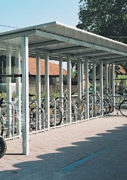
Tender specifications „RATIO Twin“ (double-sided variation 4.5)<br />
Item Description Quantity Price per unit Total price<br />
1 Base element .......................................................................................................................................................... 1<br />
Number of addition elements (field grid, 1250 mm) ......................................................................................................<br />
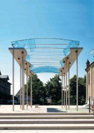
System shelter type "RATIO Twin", roof depth: 4.5 m, front clearance height: 2.2 m (4.5- 2.2) with aluminium clad flat and<br />
inclined roof in colour tone per RAL. The structure is erected as a building kit system by configuring a base element together with<br />
a number of addition elements to achieve a required length (L) for the system. Both the base element as well as addition elements<br />
are to be designed for a field grid of 1250 mm.<br />
The roofing material for both flat and inclined areas is implemented with weather resistant aluminium edge section whose geometry<br />
is to be adapted to the roof shape such that no butt-joint is created where the flat and inclined areas of the roof meet.<br />
Butt-joints in the roof's longitudinal direction occur in field grid increments or a multiple of same and must – adapted to the roof's<br />
geometry – be sealed watertight with sections and plastic seals. The roofing material is attached to its support structure - unrestricted<br />
- via special clamping sections which compensate for the various aluminium panel working movements resulting from<br />
thermal influences (use of different materials with differing expansion coefficients) without any incidence of damage. Contact corrosion<br />
caused by the direct contact of differing materials, steel and aluminium, is to be eliminated by coating the respective steel<br />
parts with a corrosion-preventing polyester layer or by using plastic buffers.<br />
The ribs for this double-sided overhanging roof structure are pre-fabricated individually from hollow steel sections, cut and welded to form<br />
the necessary angles (subsequently referred to as "V-shaped, horizontally folded staffs"), then collectively arranged on-site at a grid spacing<br />
of 1250 mm. The flat roof area's rib end pointed toward the inclined roof area is mitre cut to an angle of 45° for weld-connection to the<br />
support segment of the inclined roof area, mitre cut at both ends at a 45° angle, and in turn weld-connected to the centre piece of the<br />
identically formed opposite wing of this symmetrical roof overhang structure. The load presented by the roofing material and the external<br />
loads per DIN 1055 are borne by the "V-shaped, horizontally folded staffs". The individual elements are welded together to make the staff<br />
rigid (as described above), thus creating a homogeneous roof joist. These roof joists are supported by a beam running the length of the<br />
roof. The supporting beam is located beneath the centre of the double-winged overhang. The connection between roof joists and the supporting<br />
beam is accomplished with rigid connections to absorb exerted bend and torsion moments as well as vertical and horizontal forces.<br />
The support beam, implemented with a closed hollow section, is to be dimensioned appropriately for the various types of stress exerted<br />
on it. The connection of this hollow section to its vertical supports is to be designed as an appropriately dimensioned rigid connection<br />
oriented in the direction of torsion forces. The above-described support beam, the main vertical supports on which it rests, and also the<br />
rain gutters are to be designed to meet static requirements. The drainage of roof rainwater is accomplished by way of a specially formed<br />
steel section, the so-called "rain gutter", whose geometry is capable of handling the entire volume of rainwater caught by the flat and inclined<br />
areas of the roof. The rain gutter is positioned in the longitudinal trough formed by the double-winged roof overhang. The rain gutter is<br />
supported by, and fastened to, the longitudinal support beam; these two system components are to have a non-positive connection<br />
produced by screws. The screw locations are to be properly watertight sealed with sealing compound. The rain gutter is clamped under<br />
adjacent edges of the aluminium roofing material to guarantee that the entire volume of rainwater is caught and also to further stabilise the<br />
position of the rain gutter.<br />
The rain gutter section is to be watertight closed at both ends with welded-on end caps. Rainwater collected in the rain gutter is<br />
passed on to the shelter's main vertical supports by way of water drain stubs integrated into the rain gutter. Water exits the structure<br />
to the outside by way of above-pavement outlet stubs integrated into the main supports. It is absolutely necessary that all<br />
roof rainwater is collected and drained off in the above-described manner. Structural dimensioning is executed to meet static<br />
requirements and is to be designed for a rated snow load of 0.75 kN/m 2 . The main supports are designed to be shackled into<br />
pit foundations which, after assembly is complete, are <strong>pour</strong>-filled with concrete. The pit foundations are to be frost-free. The<br />
length (L) of the system is the determining factor whether or not the main supports at each end of the shelter must be complemented<br />
by additional intermediate supports along the longitudinal beam described above. Intermediate vertical supports are necessary<br />
if L > 3 field grid units. Intermediate vertical supports are to be positioned to achieve overall symmetry of vertical supports.<br />
Each forward end of the roof's overhangs are capped with a section that not only improves the shelter's visible appearance but<br />
also functions as a wiring channel to permit concealed wiring for desired electric fixtures. These capping sections also provide<br />
support for the extreme outer edges of the aluminium roofing material. Static requirements, in the sense of load distribution in the<br />
roof area, are not placed on these capping sections.<br />
All steel structural elements are to be coated in a duplex process.<br />
First step: hot galvanising in dip bath per DIN EN ISO 1461.<br />
Second step: powder coated in customer's choice of RAL colour tone, coating thickness 80 ... 120 my.<br />
Colour coating build-up: • Parkerizing layer<br />
• Special water-based primer<br />
• Powder coating with UV-stabilised polyester powder, baked on at about 240° C.<br />
The award of contract is contingent upon provision of a functional sample at the premises of the tender inviting office as well as<br />
the naming of a location where a structure equivalent (in the sense of >identical